civil engineering & construction instruments eng.pdfdesigning and manufacturing measuring...
TRANSCRIPT

7
• When using for special purposes, contact us.• For prices and delivery date, contact us.
About Countermeasure Against Induced Lightning Surge
Strain gage Type Civil Engineering Transducers
Measuring Instruments
Civil Engineering & Construction Instruments

7-1
7-1
CIVIL ENGINEERING & CONSTRUCTION INSTRUMENTS
Civil Engineering & Construction Transducers
Since we produced Carlson type transducers in Japan,
KYOWA has obtained many successful results in
designing and manufacturing measuring instruments
and systems for management, maintenance, design
and research of large-scale civil engineering works
and structures in Japan and abroad.
Now, KYOWA offers not only various civil engineering
transducers but also special measuring equipment,
applicable for safe execution and maintenance of
civil engineering and construction works automatic
monitoring, and data processing systems with regard
to rock bed, landslide, structure and dam behavior.
■Strain Gage Civil Engineering Transducers
■T Series Civil Engineering Transducers with Temperature Measuring Function
All KYOWA civil engineering transducers adopt self-temperature-compensated foil strain gages, for all of sensing element which are incorporated into a Wheatstone bridge. Using the strain gages, these transducers convert soil or water pressure to corresponding voltage for measurement with strain amplifiers and other peripheral equipment. The applied self-temperature-compensated foil strain gages ensure stable measurement with less drift due to temperature changes.KYOWA also provides unique civil engineering transducers which enable measurement of temperature together with strain, stress or displacement.
Though possible by Strain gage type transducers, ordinary strain gage civil engineering transducers cannot measure temperature together with strain, stress or displacement. Thus, thermometer need to be additionally installed when embedding these transducers in concrete structures.To solve such problems, KYOWA has developed civil engineering transducers with a temperature measuring function. The function is provided for strain transducers, reinforcing-bar stress transducers, stress transducers, joint transducers and water level transducers. These transducers have a platinum resistance thermometer sensor mounted at the output side of ordinary civil engineering transducers.
※For special technical terms, refer to page 9-10.
■Independent Measurement of Physical Quantity and Temperature during measurement
■Relation between Strain and Voltage of Transducer Output
Bridge Circuit of T Series
of physical quantity. Through a different circuit from the physical quantity measuring circuit, temperature is measured based on resistance change of the temperature measuring resistor. Generally, instruments providing constant-current bridge excitation are used for civil engineering transducers with a temperature measuring function and such instruments are not affected by the resistance of extension cable.
The platinum resistance thermometer sensor is connected to the output of the bridge circuit and has no electrical concern with the input of the instruments, thereby giving no effect to measurement
●Unique models available for measurement of physical quantities together with temperature.
●Nonlinearity, hysteresis and repeatability are excellent.●Stable against temperature change; no compemsation is
required with regard to thermal effect on measurement.●Since they can be connected directly to strain amplifiers
and peripheral equipment, automatic measuring systems can easily be configured.
●Excel lent env i ronmenta l capabi l i ty ensures safe measurement under adverse temperature, humidity and vibration conditions.
●Countermeasures against lightning are available.
Features
KYOWA civil engineering transducer outputs detected strain quantity in μ m/m or output voltage in mV/V or μ V/V when excited to bridge circuit with 1V. The strain value and output voltage, e, has the following relation, ε.
If the gage factor Ks is 2.00,
;and thus, if E = 1 V, 2e = ε
Accordingly, the relation between transducer voltage ouput and strain is always 1:2. when gage factor is 2e.g. 3000 μm/m → 1500 μV/V = 1.5 mV/V
e= Ks·E·ε 14
Ks : Gage factor of civil engineering transducer E : excitation voltage∴ = Ks·ε
14
eE
2 = ε eE
r
R'
R' R'
R' R
r
r
r
T Series Transducer Amplifier
Resistive Elementfor Temp. Measurement
WheatstoneBridge
Constant-Current
excitationPowerSupply
c
(White)
b
(Black)
a
(Red)
d
(Green)Output
R = Resistance of temperature measuremen resistive elementR' = Strain gage resistancer = Resistance of extension cable

7-2
7-2
CIVIL ENGINEERING & CONSTRUCTION INSTRUMENTS
● Constant-Voltage Bridge Excitation System
● Constant-Current Bridge Excitation System
Transducers(strain, pore pressure, soil pressure, reinforcing bar, stress, displacement, joint, etc.)
1-point measurement
PC
RS232C
LAN
Hub
RS232C
PC
Transducers(strain*, pore pressure*, soil pressure, reinforcing bar*,stress*, displacement, joint*, etc.)
*Temperature measuring function enables simultaneous measurement of temperature.
+ +
WGA- 710CINSTRUMENTATION AMPLIFIER
PCMemory Recorder/Analyzer
EDX-3000A
Strain AmplifiersDPM-900 Series
LAN
Hub
LAN
Hub
HIGH
HIGH
HOLD
HOLD
ZEROTRACKING
COMPARATOR
LOW
LOW
HYS ADDSMOOTH
FACTORCAL ZEROACTUAL
OPTION SET
LOCK
UNLOCKRESET
Digital indicatorWGA-710C
Data LoggerUCAM-60B(either constant voltageor constant current available)Scanner
USB-70B
Data LoggerUCAM-60B(either constant voltageor constant current available)Scanner
USB-70B
Acceleration TransducersSoil Pressure Transducers
Analog Recorder
■Small to Large-Scale Measurement for Deformation Monitoring and Control
■Measurement of Dynamic Phenomenon
■Bridge Excitation Systems for Civil Engineering TransducersTypesAmplifiers used in conjunction with civil engineering transducers are available in 2 bridge excitation systems: constant voltage and constant current. These two systems have their respective features shown in the table below, to permit selection according to measurement purposes and applications.All KYOWA strain gage transducers, including those for civil engineering, are calibrated at the factory using the constant-voltage system.
Required physical quantity = ×BBridge output voltage (μV)
Bridge excitation voltage (V) ■Reasons why the constant-current system is used for measurement through extension cableIf a 100 m long cable with cross-section 0.5 mm2 is used for connection between a KYOWA civil engineering transducer with bridge resistance of 350Ω and an amplifier of the constant-voltage bridge excitation system, sensitivity declines by approximately 2%. To avoid such inconvenience, it is recommended to use an amplifier of the constant-current bridge excitation system, which ensures measurement with less error. For details, refer to page 9-15.
■Conversion of Measured Strain (Transducer Output Voltage) to Physical QuantityStrain or voltage measured by pore pressure transducer, joint transducer or load cell is converted into physical quantity in proper engineering unit using the calibration factor stated in the Test Data Sheet as follows:
● In the case of using a strain amplifierRequired physical quantity = Measured strain (μm/m) x Awhere, A is the calibration factor indicating the physical quantity corresponding to reference equivalent strain of 1 μm/m.
● In the case of using an amplifier other than a strain amplifier or a recorder
where, B is the calibration factor indicating the physical quantity corresponding to 1 μV output per 1 V bridge excitation voltage.
* T series is provided with temperature measuring function.
Civil engineering transducers
T series transducers
Applicable gage bridge
Calculation for compensation of declined
sensitivity due to cable extension
Applications
Measurement of physical quantity possible
Measurement of physical quantity (only engineering
quantity possible)
60 to 1000Ω
Required
Measurement with cable not extended too long. Mainly for experimental measurement
Measurement through extension cable
Mainly for field measurement
Measurement of physical quantity possible
Temperature measurement together with physical
quantity possible*
350Ω
Not required
Constant-Voltage System
Constant-Current System
Bridge Excitation System
※For use under corrosive liquid or gaseous environment, contact us.
(Data transfer Only)
Short
Long
No YesNo Yes
Temp. Measurement with T Series
Bridge Excitation of Measuring InstrumentCable
Constant voltage Constant currentConstant currentConstant current

7-3
7-3
CIVIL ENGINEERING & CONSTRUCTION INSTRUMENTS
Field-Use Extension Cables
■Bridge Circuit and Cable Connection of Civil Engineering Transducer
Field-Use Extension Cables for Long-Term MeasurementMost of cables attached to KYOWA civil engineering t ransducers are 1m long to enable opt imum connection between transducers and amplifiers using extension cables matched with the distance in the field. Civil engineering and construction measurement is carried out for a comparatively long period of time, thereby requiring not only transducers but also extension cables to be durable and reliable. KYOWA has been developing field-use extension cables considering them as important parts of transducers. To maintain the insulation resistance of extension cables, KYOWA adopts the ethylene-propylene rubber which features high insulation resistance. Also, all KYOWA extension cables are rubber-filled to ensure reliable performance for a long period of time. Select the most suitable one by considering the application, field conditions and tensile strength.
Note: ●Cold-resistant, heat-resistant and oil-resistant cables are also available.●For a multiple-conductor cable to extend multiple transducer cables with
a single cable, contact a KYOWA sales representative.● For the cable joint, use JB-100C, JB-200A or JB-210A.●For a long-term measurement, use highly reliable KYOWA genuine cable.
Name
Model
Externa diameter
Application
Insulator
Structure
Tensile Strength
Sheath
Shield
4-conductor (0.5 mm2)
shielded cabtyre cable
K-PNCT-SB (1)4×0.5
Surface laying
8.5
Approx. 147 N
Static measurement Dynamic measurement
Chloroprene cabtyre
Mesh shield
EP rubber insulator
Rubber-filled type
4-conductor(0.5 mm2)
rubber-filled shieldedabtyre cable
TF-0.5(K-PNCT-SB (2)
4×0.5)
Surface layingEmbedded in concrete
11.5
Approx. 147 N
4-conductor(0.5 mm2)
rubber-filled shielded, Toughrex-sheathed
K-PNCT-SB (2)TX(FE) ZV4×0.5
Sunface laying Embedded inbank
22
Approx. 147 N Armouring pipe
2.942 kN
4-Conductor Cabtyre Cable
Rubber-Filled Shielded Cable
Rubber-Filled Toughrex Cable
Type
● In the case of the cable bared at the tip
■Rubber-Filled Toughrex Cable
■4-Conductor Cabtyre Cable
■Rubber-Filled Shielded Cable Conductor
Shield layer
Rubber inclusion
Conductor Color Codes
Separator
EP rubber insulatorFilled with rubber
Separator
Separator
Chloroprenecabtyre sheath
Conductor
Holding tape
Shield layer
Conductor Color Codes
Separator
EP rubber insulatorInclusion
Separator
Chloroprenecabtyre sheath
Conductor
Conductor Color Codes
Separator
EP rubber insulator
Rubber inclusion
Rubber coatedfabric tape
Shield mesh
Chloroprenecabtyre sheath
Toughrex sheath
Corrosion-proofvinyl layer
Bk Wt
RdGn
Bk Wt
RdGn
Bk Wt
RdGn
+
+
-
-
+
+
-
-
ABC D E
FG
+
+
-
-
Green
White
Black
ShieldRed
(Constant-voltageor constant-currentexcitation)
(Constant-currentexcitation)
Temp. measuring resistor
Green
Green
White
White
Black
Black
ShieldRed
Red
Input
Input
Input
Out
put
Out
put
(Vol
tage
)(V
olta
ge)
(Vol
tage
)
Out
put
Plug
Shield wire(Constant-voltageor constant-currentexcitation)
For most of transducers,the shield wire is notconnected to the case.
● In the case of the cable terminated with NDIS connector plug
● Civil engineering transducer with temp. measuring function and with the cable bared at the tip
7-4
7-4
CIVIL ENGINEERING & CONSTRUCTION INSTRUMENTS
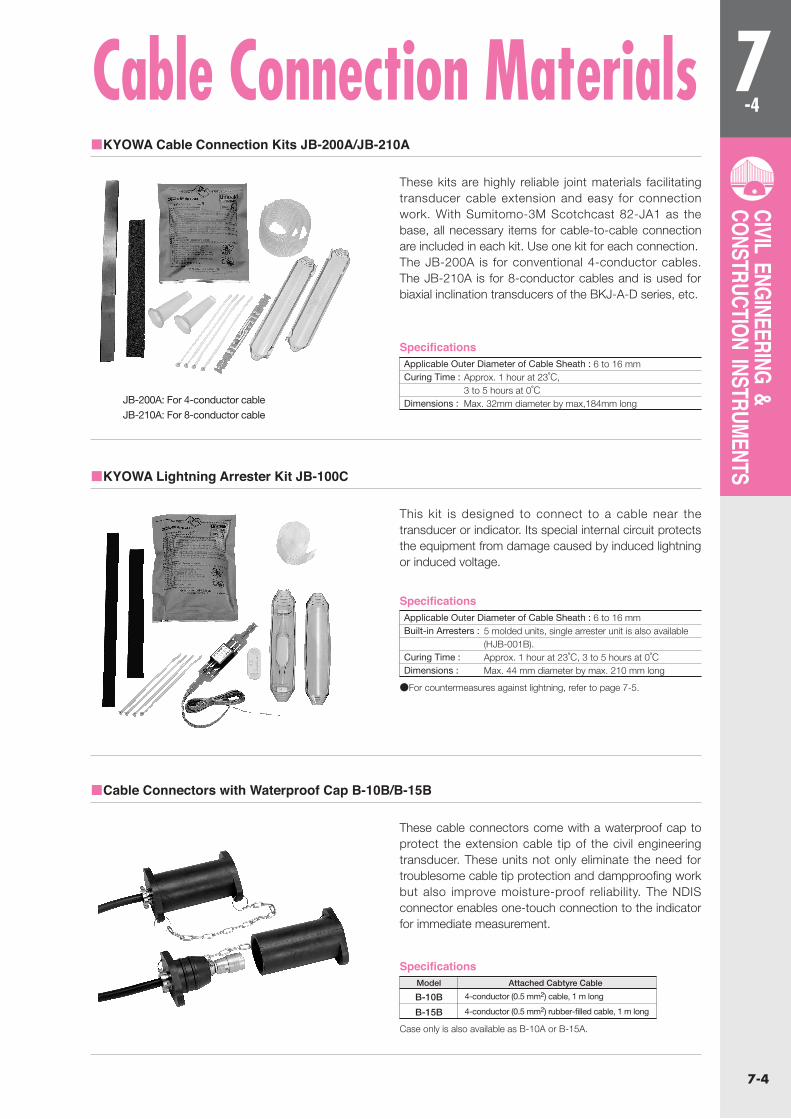
Cable Connection Materials■KYOWA Cable Connection Kits JB-200A/JB-210A
■KYOWA Lightning Arrester Kit JB-100C
■Cable Connectors with Waterproof Cap B-10B/B-15B
These kits are highly reliable joint materials facilitating transducer cable extension and easy for connection work. With Sumitomo-3M Scotchcast 82-JA1 as the base, all necessary items for cable-to-cable connection are included in each kit. Use one kit for each connection. The JB-200A is for conventional 4-conductor cables. The JB-210A is for 8-conductor cables and is used for biaxial inclination transducers of the BKJ-A-D series, etc.
This kit is designed to connect to a cable near the transducer or indicator. Its special internal circuit protects the equipment from damage caused by induced lightning or induced voltage.
These cable connectors come with a waterproof cap to protect the extension cable tip of the civil engineering transducer. These units not only eliminate the need for troublesome cable tip protection and dampproofing work but also improve moisture-proof reliability. The NDIS connector enables one-touch connection to the indicator for immediate measurement.
Specifications
Specifications
Specifications
Applicable Outer Diameter of Cable Sheath : 6 to 16 mmBuilt-in Arresters : 5 molded units, single arrester unit is also available (HJB-001B).Curing Time : Approx. 1 hour at 23℃, 3 to 5 hours at 0℃Dimensions : Max. 44 mm diameter by max. 210 mm long
Applicable Outer Diameter of Cable Sheath : 6 to 16 mmCuring Time : Approx. 1 hour at 23℃, 3 to 5 hours at 0℃ Dimensions : Max. 32mm diameter by max,184mm longJB-200A: For 4-conductor cable
JB-210A: For 8-conductor cable
B-10B
B-15B
4-conductor (0.5 mm2) cable, 1 m long
4-conductor (0.5 mm2) rubber-filled cable, 1 m long
Model
●For countermeasures against lightning, refer to page 7-5.
Case only is also available as B-10A or B-15A.
Attached Cabtyre Cable
7-5
7-5
CIVIL ENGINEERING & CONSTRUCTION INSTRUMENTS
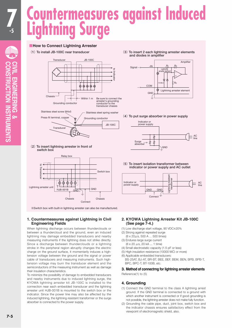
Countermeasures against Induced Lightning Surge
1. Countermeasures against Lightning in Civil Engineering Fields
2. KYOWA Lightning Arrester Kit JB-100C (See page 7-4.)
When lightning discharge occurs between thunderclouds or between a thundercloud and the ground, even an induced lightning may damage embedded transducers and nearby measuring instruments if the lightning does not strike directly. Since a discharge between thunderclouds or a lightning stroke in the peripheral region abruptly changes the electric charge on the ground surface, it momentarily induces a high-tension voltage between the ground and the signal or power cable of transducers and measuring instruments. Such high-tension voltage may burn the transducer element and the semiconductors of the measuring instrument as well as damage their insulation characteristics.To minimize the possibility of damage to embedded transducers and nearby instruments due to induced lightning surge, the KYOWA lightning arrester kit JB-100C is installed to the connection near each embedded transducer and the lightning arrester unit HJB-001B is mounted to the switch box or the indicator. Since the power line may also be affected by the induced lightning, the lightning resistant transformer or the surge absorber is connected to the power supply.
(1) Low discharge start voltage, 90 VDC±20%(2) Strong against repeated surge (8 x 20μs, 500 A ... 500 times)(3) Endures large surge current (8 x 20 μs, 20 kA ... 1 time)(4) Small electrostatic capacity (1.5 pF or less)(5) High insulation resistance (10000 MΩ or more)(6) Applicable embedded transducers: BS-25AT, BJ-AT, BR-BT, BEE, BEF, BEM, BEN, BPB, BPB-T, BPC, BPC-T, BT-100B, etc.
4. Grounding
3. Method of connectrng for lightning arrester elements
(1) Connect the GND terminal to the class A lightning arrest ground. If the GND terminal is connected to a ground with which another instrument is connected or if good grounding is not possible, the lightning arrester does not make fully function.
(2) Grounding the cable pipe, duct, joint box, switch box and the indicator chassis ensures satisfactory effect from the viewpoint of electromagnetic shield, also.
Reference(1) to (5)
■How to Connect Lightning Arrester(1) To install JB-100C near transducer
(2) To insert lightning arrester in front of switch box
(3) To insert 2 each lightning arrester elements and diodes in amplifier
(4) To put surge absorber in power supply
(5) To insert isolation transformer between indicator or power supply and AC outlet
※Switch box with built-in lightning arrester can also be manufactured.
GND
ACline
ACline
GND
GND
Surgeabsorber
Indicator orpower supply
Grounding conductor
Within 1 m Be sure to connect thearrester’s groundingconductor to thetransducer chassis
Stainless steel screw M4x5
Relay box
Switch box
Indicator orpower supply
Connect
Connect
JB-100C
Amplifier
GND
COM
-IN R1 R2
R
+
-Lightning
arrester element
Lightning arrester element
1S1588×2 3
HJB-001B GNDGND
Chassis
Signal
Press-fit terminal, copper
Transducer
Stainless steel spring washer
Grounding conductor
Ligh
tnin
g re
sist
ant
trans
form
er
Transducer JB-100C
to Indicator
to Transducer
ChassisChassis
Lightning arrester unit

7-6
7-6
CIVIL ENGINEERING & CONSTRUCTION INSTRUMENTS
x(-)(+)
x(-)(+)Y(-)(+)
250
228
M5 d=10
M5 d=10
56.5
φ27
56.5
350
328
φ27
M5 d=10
M5 d=10
5
(56.8)
9
60
φ55.6t=1.6
66.1
φ60.5
BKJ-AEmbedment Type Inclination Transducers
■Dimensions
Small-sized and lightweight 27mm in outer diameter. Inclination angles detected at multiple stages enable measurement of lateral displacement of the ground or earth retaining wall.
The BKJ-A series inclination transducers are designed for embedment at multiple stages in a boring or earth retaining wall. Inclination angles detected at mutiple stages enable measurement of lateral displacement of the ground or earth retaining wall. Since the embedment method ensures quicker measurement than the insertion method, the BKJ-A series is suitable for use in information-oriented urban civil engineering fields.The BKJ-A series can be installed at maximum 20 stages in an aluminum guide pipe embedded beforehand.
●Facilitate quicker and easy data recording since the BKJ-A series is installed in an aluminum guide pipe embedded beforehand in a boring or earth retaining wall.
●Allows installation at maximum 20 stages in a guide pipe.●Available in uniaxial and biaxial types for selection to meet
individual applications●Designed for high immunity against lightning surge
Dedicated aluminum guide pipe B-30, 3 m longDedicated socket B-35, 30 cm long
To Ensure Safe UsageTo protect the cable, it is recommended to connect the dedicated aluminum guide pipe using an adhesive or screws (M4×4).Do not use rivets.
BKJ-A-5BKJ-A-10BKJ-A-5-DBKJ-A-10-D
±5° ±10°±5° ±10°
1kg
1.2kg
1(uniaxial)
2(biaxial)
Rated Capacity Weight(Approx.) ModelMeasuring Directions
BKJ-A
GuifePipe Socker
BKJ-A-D
Safe Temperature Range : -20 to 70℃Compensated Temperature Range : -10 to 60℃Temperature Effect on Zero Balance : Within±0.05% RO/℃Temperature Effect on Output : Within±0.1%/℃
●Inclination Measurement ●±5°, ±10°
Safe Overload Rating:
Material:
Protection Rating:
Weight:
120%
Stainless steel (quide blade resin)
IP68(JIS C 0920)Water resistance 490kPa
See table below
Recommended Excitation Voltage : 2 to 10 V AC or DC
Input Resistance : 350Ω±1%
Output Resistance : 350Ω±1%
Cable : BKJ-A : 4-conductor (0.3 mm2) chloroprene shielded cable,
6 mm diameter by 1 m long, bare at the tip
BKJ-A-D : 8-conductor (0.3 mm2) chloroprene shielded cable,
6 mm diameter by 1 m long, bared at the tip
Rated Capacity : See table below.
Nonlinearity : Within±0.5%RO
Hysteresis : Within±0.5%RO
Rated Output : 1.4 mV/V (2800μm/m) or more
(minus rated capacity to plus rated capacity)
Optional Accessories
SpecificationsPerformance
Environmental Characteristics
Electrical Characteristics
Mechanical Properties
7-7
7-7
CIVIL ENGINEERING & CONSTRUCTION INSTRUMENTS
5
(56.8)
9
60
φ55.6t=1.6
66.1
φ60.5
(-)(+)x
25
59
Guide Roller
Guide Roller
M5 d=10
φ27
250
350
450
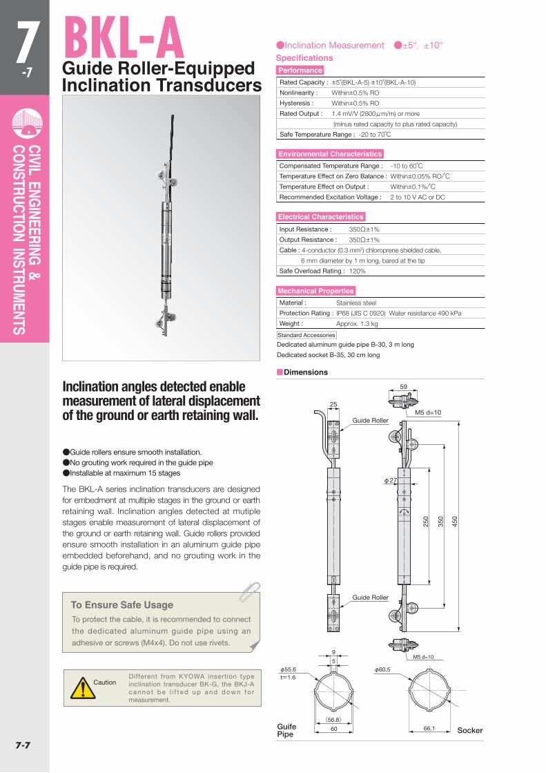
BKL-AGuide Roller-Equipped Inclination Transducers
Inclination angles detected enable measurement of lateral displacement of the ground or earth retaining wall.
The BKL-A series inclination transducers are designed for embedment at multiple stages in the ground or earth retaining wall. Inclination angles detected at mutiple stages enable measurement of lateral displacement of the ground or earth retaining wall. Guide rollers provided ensure smooth installation in an aluminum guide pipe embedded beforehand, and no grouting work in the guide pipe is required.
●Guide rollers ensure smooth installation.●No grouting work required in the guide pipe●Installable at maximum 15 stages
To Ensure Safe UsageTo protect the cable, it is recommended to connect
the dedicated aluminum guide pipe using an
adhesive or screws (M4x4). Do not use rivets.
CautionDifferent from KYOWA insertion type inclination transducer BK-G, the BKJ-A canno t be l i f t ed up and down fo r measurement.
●Inclination Measurement ●±5°, ±10°
Dedicated aluminum guide pipe B-30, 3 m long
Dedicated socket B-35, 30 cm long
Rated Capacity : ±5°(BKL-A-5) ±10°(BKL-A-10)
Nonlinearity : Within±0.5% RO
Hysteresis : Within±0.5% RO
Rated Output : 1.4 mV/V (2800μm/m) or more
(minus rated capacity to plus rated capacity) Safe Temperature Range : -20 to 70℃
Compensated Temperature Range : -10 to 60℃
Temperature Effect on Zero Balance : Within±0.05% RO/℃Temperature Effect on Output : Within±0.1%/℃Recommended Excitation Voltage : 2 to 10 V AC or DC
Input Resistance : 350Ω±1%
Output Resistance : 350Ω±1%
Cable : 4-conductor (0.3 mm2) chloroprene shielded cable,
6 mm diameter by 1 m long, bared at the tip
Safe Overload Rating : 120%
Material : Stainless steel
Protection Rating : IP68 (JIS C 0920) Water resistance 490 kPa
Weight : Approx. 1.3 kg
GuifePipe Socker
SpecificationsPerformance
Environmental Characteristics
Electrical Characteristics
Mechanical Properties
Standard Accessories
■Dimensions

7-8
7-8
CIVIL ENGINEERING & CONSTRUCTION INSTRUMENTS
5
(56.8)
9
60
φ55.6t=1.6
66.1
φ60.5
BK-GInsertion Type Inclination Transducers
●Inclination Measurement ●±5°,±10°
BK-G series inclination transducers are designed for insertion in guide pipe embedded beforehand, in the ground or the structure, detect successive inclination angles and measure lateral displacement.And are indispensable to check for landslide or earth retaining wall, many use for lateral displacement of the ground or earth retaining wall.
●Highly reliable performance backed by durable structure ensure safe use in civil engineering fields.●Cable and reel are standard accessories:the cable
enables measurement up to 50m deep.
Dedicated aluminum guide pipe B-30 (3m long)Pipe receptacle B-35(30cm long)
※60m long or cable can be manufactured.
+ -
φ34
500
660
(410)
(276)
Inclination angles detected enable measurement of lateral displacement of the ground or earth retaining wall.
Rated Capacity : BK-5G ±5° BK-10G ±10°Nonlinearity : Within±0.5%RO
Hysteresis : Within±0.5%RO
Rated Output : 2.182mV/V(4364×10-6μm/m)±0.5% (from minus rated capacity to plus rated capacity)
Safe temperature Range : -20 to 60℃Compensaated Temperature Range : -20 to 50℃Temperature Effect on Zero Balance : Within±0.03%RO/℃Temperature Effect on Output : Within±0.03%/℃
Input Resistance : 500 to 660ΩOutput Resistance : 343 to 357ΩCable : 4-conducter (0.5mm2) piano-wire-reinforced chloroprene-shielded cable of
60m long (contact a kyowa representative for a cable of longer than 50m)
Safe over load Rating : 120%
Weight : Approx.3.2kg
GuifePipe Socker
SpecificationsPerformance
Environmental Characteristics
Electrical Characteristics
Mechanical Properties
Optional Accessories
■Dimensions
7-9
7-9
CIVIL ENGINEERING & CONSTRUCTION INSTRUMENTS
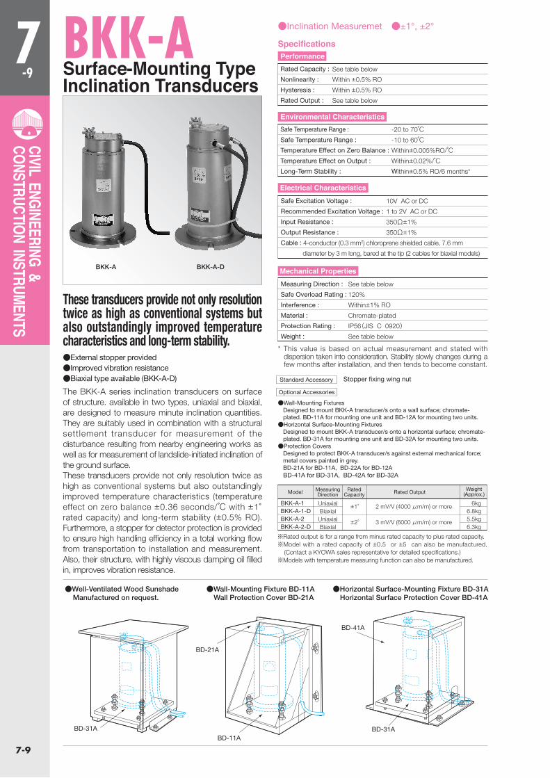
BKK-ASurface-Mounting TypeInclination Transducers
BKK-A BKK-A-D
●Inclination Measuremet ●±1°, ±2°
These transducers provide not only resolution twice as high as conventional systems but also outstandingly improved temperature characteristics and long-term stability.
The BKK-A series inclination transducers on surface of structure. available in two types, uniaxial and biaxial, are designed to measure minute inclination quantities. They are suitably used in combination with a structural settlement transducer for measurement of the disturbance resulting from nearby engineering works as well as for measurement of landslide-initiated inclination of the ground surface. These transducers provide not only resolution twice as high as conventional systems but also outstandingly improved temperature characteristics (temperature effect on zero balance ±0.36 seconds/℃ with ±1°rated capacity) and long-term stability (±0.5% RO). Furthermore, a stopper for detector protection is provided to ensure high handling efficiency in a total working flow from transportation to installation and measurement. Also, their structure, with highly viscous damping oil filled in, improves vibration resistance.
●External stopper provided●Improved vibration resistance●Biaxial type available (BKK-A-D) Stopper fixing wing nut
●Wall-Mounting FixturesDesigned to mount BKK-A transducer/s onto a wall surface; chromate-plated. BD-11A for mounting one unit and BD-12A for mounting two units.●Horizontal Surface-Mounting Fixtures
Designed to mount BKK-A transducer/s onto a horizontal surface; chromate-plated. BD-31A for mounting one unit and BD-32A for mounting two units.●Protection Covers
Designed to protect BKK-A transducer/s against external mechanical force; metal covers painted in grey.BD-21A for BD-11A, BD-22A for BD-12ABD-41A for BD-31A, BD-42A for BD-32A
* This value is based on actual measurement and stated with dispersion taken into consideration. Stability slowly changes during a few months after installation, and then tends to become constant.
※Rated output is for a range from minus rated capacity to plus rated capacity.※Model with a rated capacity of ±0.5 or ±5 can also be manufactured.
(Contact a KYOWA sales representative for detailed specifications.)※Models with temperature measuring function can also be manufactured.
BKK-A-1BKK-A-1-DBKK-A-2BKK-A-2-D
UniaxialBiaxialUniaxialBiaxial
±1°
±2°
2 mV/V (4000 μm/m) or more
3 mV/V (6000 μm/m) or more
6kg6.8kg5.5kg6.3kg
MeasuringDirection
RatedCapacity
Weight(Approx.)Rated OutputModel
●Well-Ventilated Wood Sunshade Manufactured on request.
●Wall-Mounting Fixture BD-11A Wall Protection Cover BD-21A
●Horizontal Surface-Mounting Fixture BD-31A Horizontal Surface Protection Cover BD-41A
Rated Capacity : See table below
Nonlinearity : Within ±0.5% RO
Hysteresis : Within ±0.5% RO
Rated Output : See table below
Safe Temperature Range : -20 to 70℃Safe Temperature Range : -10 to 60℃Temperature Effect on Zero Balance : Within±0.005%RO/℃Temperature Effect on Output : Within±0.02%/℃Long-Term Stability : Within±0.5% RO/6 months*
Safe Excitation Voltage : 10V AC or DC
Recommended Excitation Voltage : 1 to 2V AC or DC
Input Resistance : 350Ω±1%
Output Resistance : 350Ω±1%
Cable : 4-conductor (0.3 mm2) chloroprene shielded cable, 7.6 mm
diameter by 3 m long, bared at the tip (2 cables for biaxial models)
Measuring Direction : See table below
Safe Overload Rating : 120%
Interference : Within±1% RO
Material : Chromate-plated
Protection Rating : IP56(JIS C 0920)Weight : See table below
SpecificationsPerformance
Environmental Characteristics
Electrical Characteristics
Mechanical Properties
Standard Accessory
Optional Accessories
BD-11A
BD-21A
BD-41A
BD-31ABD-31A
7-10
7-10
CIVIL ENGINEERING & CONSTRUCTION INSTRUMENTS
(+)(-)(-) (-)x方向 感度方向 感度
φ120
M4
11
φ89
(7)
(10)(
7)(
10)
208
8
(+)感度方向 19
4
φ140
φ120
11
M4
φ89
218
8
φ1403×M10Anchor boltfor installation
3×M10Anchor boltfor installation
196
■Dimensions
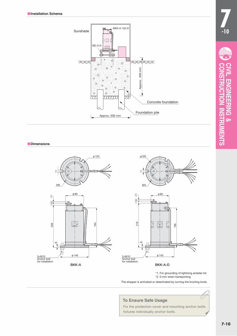
■Installation Schema
To Ensure Safe UsageFix the protection cover and mounting anchor bolts
fixtures individually anchor bolts.
BKK-A BKK-A-D
*1. For grounding of lightning arrester kit.*2. 0 mm when transporting.
The stopper is activated or deactivated by turning the knurling knob.
Sunshade
Concrete foundation
(+)X 感度方向 方向 感度
BKK-A-1(2)-D
BD-31A
App
rox.
500
mm
Foundation pile Approx. 500 mm
7-11
7-11
CIVIL ENGINEERING & CONSTRUCTION INSTRUMENTS
(32)
(32)
φ98
15(
60)
82
φ26
(17)φ98
(7) (
7)
(φ33
)
(φ
33)
φ70
φ129
M4 d=4*
6×M12 d=12
12×M8 d=12
M4 Hexagon nut
8×M6 d=8
(φ41)
1.5
18(
70)
95
1.5 (φ41)
φ129 (18)
φ100φ26
3(
74)
380
40
(11)
(3.2)φ90φ68φ55φ43
110
408
φ80φ91φ109φ115
φ61 φ100
30
(38) (27)
(φ33
)
(32)
(φ33
)
(32)
(74)
4×M10 d=10
M4 d=4*
M4 d=4*
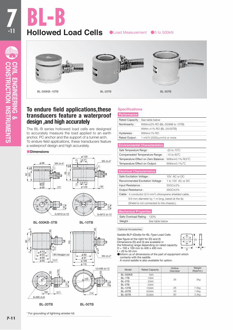
BL-BHollowed Load Cells
BL-500KB~10TB BL-20TB BL-50TB
●Load Measurement ●5 to 500kN
■Dimensions
To endure field applications,these transducers feature a waterproof design ,and high accuratelyThe BL-B series hollowed load cells are designed to accurately measure the load applied to an earth anchor, PC anchor and the support of a tunnel arch. To endure field applications, these transducers feature a waterproof design and high accurately.
BL-500KBBL-1TBBL-2TBBL-5TBBL-10TBBL-20TBBL-50TB
5kN10kN20kN50kN
100kN200kN500kN
26
264380
3kg
7.5kg1.6kg3.3kg
Rated CapacityWeight
(Approx.)Hollow
DiameterModel
See figure at the right for (D) and (t)Dimensions (D) and (t) are available in the following range depending on rated capacity.D = 100 x 100 mm to 400 x 400 mmt = 20 to 50 mm●Inform us of dimensions of the part of equipment which contacts with the saddle. A round saddle is also available for option.
Saddle BLP-(D)x(t)s for BL-Type Load Cells
BL-500KB~5TB BL-10TB
BL-20TB BL-50TB
D t
D
Rated Capacity : See table below
Nonlinearity : Within±2% RO (BL-500KB to 10TB)
Within ±1% RO (BL-20/50TB)
Hysteresis : Within±1% RO
Rated Output : 1 mV/V (2000μm/m) or more
Safe Temperature Range : -20 to 70℃Compensated Temperature Range : -10 to 60℃Temperature Effect on Zero Balance : Within±0.1% RO/℃Temperature Effect on Output : Within±0.1%/℃
Safe Excitation Voltage : 10V AC or DC
Recommended Excitation Voltage : 1 to 10V AC or DC
Input Resistance : 350Ω±2%
Output Resistance : 350Ω±2%
Cable : 4-conductor (0.5 mm2) chloroprene shielded cable,
9.6 mm diameter by 1 m long, bared at the tip
(Shield is not connected to the chassis.)
Safe Overload Rating : 120%
Weight : See table below
SpecificationsPerformance
Environmental Characteristics
Electrical Characteristics
Mechanical Properties
Optional Accessories
* For grounding of lightning arrester kit.

7-12
7-12
CIVIL ENGINEERING & CONSTRUCTION INSTRUMENTS
BLW-AHollowed Load Cells
●Load Measurement ●500kN to 2MN
■Dimensions
■Application Sample
To endure field applications,these transducers feature a waterproof design,Lightweight,Thin design.
Designed to measure load of VSL anchor, etc.
●Eccentric load or inner/outer load causes less sensitivity deviation.
●Large center hollow making it suitable for VSL method●Waterproof structure, protection rating IP68 (0.5 MPa for
24 hours at 23℃±15℃)●Thin design●Lightweight
BLW-A-500KNBLW-A-1MNBLW-A-1500KNBLW-A-2MN
188223.5263.5263.5
500kN1MN
1500kN2MN
175210250250
125144155155
64829494
131150161161
170205245245
45°52°46°60°
4kg8kg
14kg14.5kg
(A) φB (φC) H φE φF (G) Weight(Appox)Model Rated capgcity
Tension measurement of earth retaining or retaining wall
Hollow diameter
Rated Capacity : See table below
Nonlinearity : Within±0.8% RO
Hysteresis : Within±0.5% RO
Rated Output : 1.25 mV/V (2500μm/m) or more
Safe Temperature Range : -20 to 70℃Compensated Temperature Range : -10 to 60℃Temperature Effect on Zero Balance : Within±0.05% RO/℃Temperature Effect on Output : Within±0.05%/℃
Safe Excitation Voltage : 15V AC or DC
Recommended Excitation Voltage : 1 to 10V AC or DC
Input Resistance : 350Ω±0.3%
Output Resistance : 350Ω±2%
Cable : 4-conductor (0.5 mm2) chloroprene shielded cable,
9.6 mm diameter by 1 m long, bared at the tip
(Shield is not connected to the chassis.)
Safe Overload Rating : 150%
Protection Rating : IP68 (endures 0.5 MPa water pressure
for 24 hours at 23℃ ±15℃)
Weight : See table below
SpecificationsPerformance
Environmental Characteristics
Electrical Characteristics
Mechanical Properties
* Screw hole for mounting the grounding terminal of lightning arrester kit.
Anchor plate
Hollowed load cell
PC steel twisted wire
(G)
40
φEφF
120°
(A)φB(φC)
H2
2
M4 d=5*

7-13
7-13
CIVIL ENGINEERING & CONSTRUCTION INSTRUMENTS
BL-EHollowed Load Cells ●Load Measurement ●1 & 2 MN
■Dimensions
To endure field applications,these transducers feature a waterproof design ,and high accurately
The BL-E series hollowed load cells are designed to accurately measure the load applied to an earth anchor, PC anchor and the support of a tunnel arch. To endure field applications, these transducers feature a waterproof design and high accurately.
BL-100TEBL-200TE
1MN2MN
85133
98150
128190
140210
113170
66101
110120
6.6kg14.1kg
Rated Capacity φA φB φC φD φE (G) HWeight
(Approx.)Model
φA: Hollow diameter
Rated Capacity : See table below
Nonlinearity : Within±2% RO
Hysteresis : Within±1% RO
Rated Output : 1 mV/V (2000μm/m) or more
Safe Temperature Range : -20 to 70℃Compensated Temperature Range : -10 to 60℃Temperature Effect on Zero Balance : Within±0.1% RO/℃Temperature Effect on Output : Within±0.1%/℃
Safe Overload Rating : 120%
Weight : See table below
Safe Excitation Voltage : 10V AC or DC
Recommended Excitation Voltage : 1 to 10V AC or DC
Input Resistance : 350Ω±2%
Output Resistance : 350Ω±2%
Cable : 4-conductor (0.5 mm2) chloroprene shielded cable,
9.6 mm diameter by 1 m long, bared at the tip
(Shield is not connected to the chassis.)
Saddle BLP-(D)x(t)s for BL-Type Load Cells and (t) are available in the following range depending on rated capacity.D = 100 x 100 mm to 400 x 400 mmt = 20 to 50 mm●Inform us of dimensions of the part of equipment which contacts with the saddle. A round saddle is also available for option.
D t
D
Optional Accessories
SpecificationsPerformance
Environmental Characteristics
Electrical Characteristics
Mechanical Properties
* For grounding of lightning arrester kit.
φE
40
φ33
(15)
12×M12 d=10
M4 d=5*
5(G)
φD
(9)
(19)
(0.
5)
H
φAφBφC
7-14
7-14
CIVIL ENGINEERING & CONSTRUCTION INSTRUMENTS
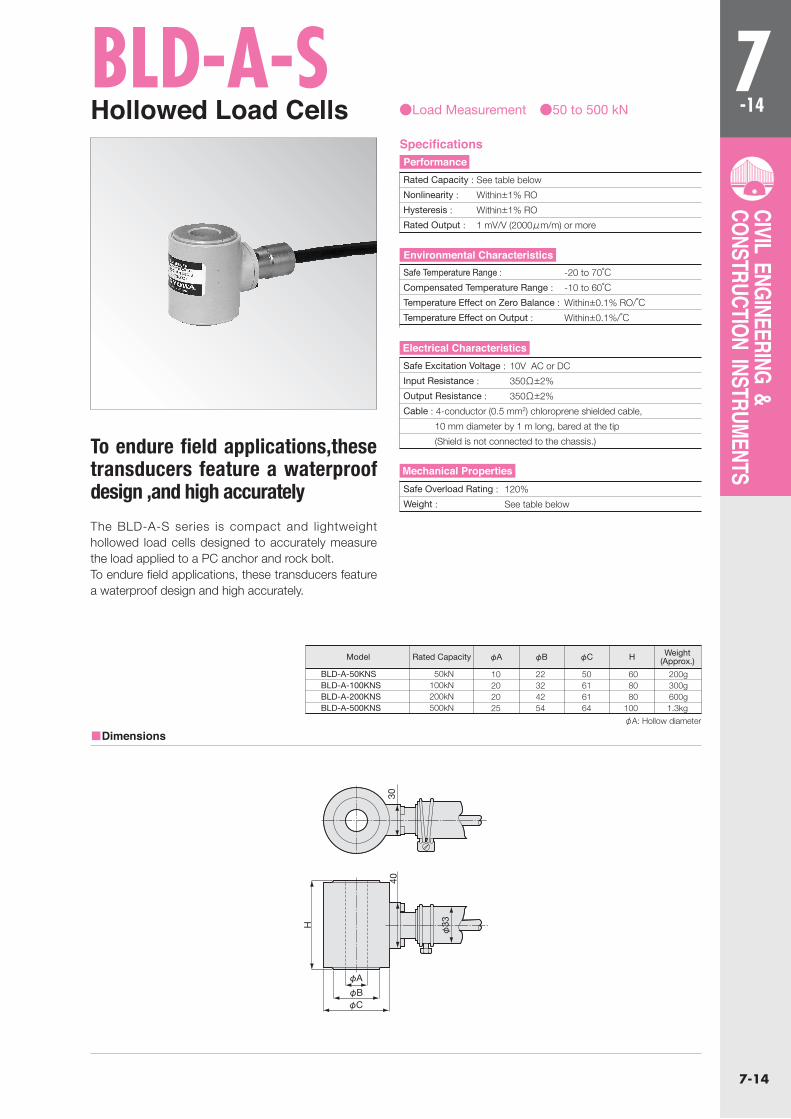
BLD-A-SHollowed Load Cells ●Load Measurement ●50 to 500 kN
To endure field applications,these transducers feature a waterproof design ,and high accurately
The BLD-A-S series is compact and lightweight hollowed load cells designed to accurately measure the load applied to a PC anchor and rock bolt. To endure field applications, these transducers feature a waterproof design and high accurately.
BLD-A-50KNSBLD-A-100KNSBLD-A-200KNSBLD-A-500KNS
10202025
50kN100kN200kN500kN
22324254
50616164
608080
100
200g300g600g1.3kg
φARated Capacity φB φC H Weight (Approx.)Model
φA: Hollow diameter
■Dimensions
Rated Capacity : See table below
Nonlinearity : Within±1% RO
Hysteresis : Within±1% RO
Rated Output : 1 mV/V (2000μm/m) or more
Safe Temperature Range : -20 to 70℃Compensated Temperature Range : -10 to 60℃Temperature Effect on Zero Balance : Within±0.1% RO/℃Temperature Effect on Output : Within±0.1%/℃
Safe Excitation Voltage : 10V AC or DC
Input Resistance : 350Ω±2%
Output Resistance : 350Ω±2%
Cable : 4-conductor (0.5 mm2) chloroprene shielded cable,
10 mm diameter by 1 m long, bared at the tip
(Shield is not connected to the chassis.)
Safe Overload Rating : 120%
Weight : See table below
SpecificationsPerformance
Environmental Characteristics
Electrical Characteristics
Mechanical Properties
30
H
φ33
40
φA
φBφC
7-15
7-15
CIVIL ENGINEERING & CONSTRUCTION INSTRUMENTS
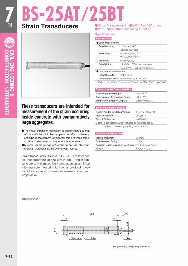
BS-25AT/25BT●Strain Measurement ●±500 & ±1000 μm/m ●With Temperature Measuring Function
These transducers are intended for measurement of the strain occurring inside concrete with comparatively large aggregates.
Strain transducers BS-25AT/BS-25BT are intended for measurement of the strain occurring inside concrete with comparatively large aggregates. Since a temperature measuring function is provided, these transducers can simultaneously measure strain and temperature.
●The linear expansion coefficient is approximated to that of concrete to minimize temperature effects, thereby enabling measurement of external force-initiated strain and the strain corresponding to temperature stress.
●Minimal damage against embedment vibrator and endures vibration initiated by the RCD method.
■Dimensions
Strain Transducers
●Strain Measurement
Rated Capacity : ±500μm/m(AT) ±1000μm/m(BT) Nonlinearity : Within±1.5%RO (AT) Within±2%RO (BT) Hysteresis : Within±2%RO
Rated Output : ±1 mV/V (±2000μm/m) or more
±0.5 mV/V (±1000μm/m) or more
●Temperature Measurement
Rated Capacity : -30 to 70℃ Measurement Error : Within ±0.5℃ (-30 to 70℃)
(Refer to Small-Sized Temperature Transducer BTS-100AT, page 7-30.)
Safe Temperature Range : -30 to 80℃Compensated Temperature Range : -20 to 70℃Temperature Effect on Output : Within±0.05%/℃
Recommended Excitation Voltage : 2 to 10V AC or DC
Input Resistance : 350Ω±1%
Output Resistance : 450Ω±0.8%
Cable : 4-conductor (0.5 mm2) chloroprene shielded cable,
11.5 mm diameter by 1 m long, bared at the tip
Instrument Length : 250mm
Safe Overload Rating : 120%
Apparent Linear Expansion Coefficient : (11.5±0.6)μm/m/℃Weight : Approx. 600 g
SpecificationsPerformance
Environmental Characteristics
Electrical Characteristics
Mechanical Properties
* For grounding of lightning arrester kit.
250
TubeVinyl tape M4*
(15)
6 6
φ22
φ30
φ37
7-16
7-16
CIVIL ENGINEERING & CONSTRUCTION INSTRUMENTS
BS-8FTSmall-Sized Strain Transducer ●Strain Measurement ●±1000 μm/m
●With Temperature Measuring Function
■Dimensions
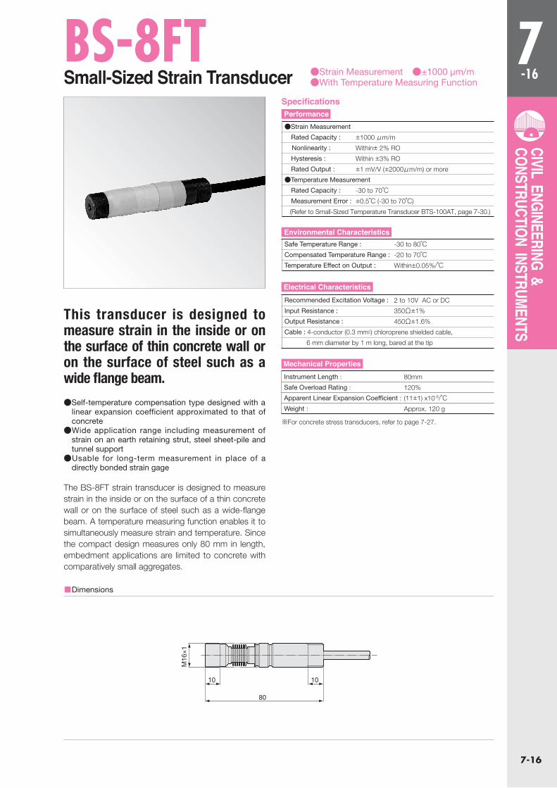
This transducer is designed to measure strain in the inside or on the surface of thin concrete wall or on the surface of steel such as a wide flange beam.
The BS-8FT strain transducer is designed to measure strain in the inside or on the surface of a thin concrete wall or on the surface of steel such as a wide-flange beam. A temperature measuring function enables it to simultaneously measure strain and temperature. Since the compact design measures only 80 mm in length, embedment applications are limited to concrete with comparatively small aggregates.
●Self-temperature compensation type designed with a linear expansion coefficient approximated to that of concrete
●Wide application range including measurement of strain on an earth retaining strut, steel sheet-pile and tunnel support
●Usable for long-term measurement in place of a directly bonded strain gage
※For concrete stress transducers, refer to page 7-27.
●Strain Measurement
Rated Capacity : ±1000 μm/m
Nonlinearity : Within± 2% RO
Hysteresis : Within ±3% RO
Rated Output : ±1 mV/V (±2000μm/m) or more
●Temperature Measurement
Rated Capacity : -30 to 70℃ Measurement Error : ±0.5℃ (-30 to 70℃)
(Refer to Small-Sized Temperature Transducer BTS-100AT, page 7-30.)
Safe Temperature Range : -30 to 80℃Compensated Temperature Range : -20 to 70℃Temperature Effect on Output : Within±0.05%/℃
Recommended Excitation Voltage : 2 to 10V AC or DC
Input Resistance : 350Ω±1%
Output Resistance : 450Ω±1.6%
Cable : 4-conductor (0.3 mm2) chloroprene shielded cable,
6 mm diameter by 1 m long, bared at the tip
Instrument Length : 80mm
Safe Overload Rating : 120%
Apparent Linear Expansion Coefficient : (11±1) x10-6/℃Weight : Approx. 120 g
SpecificationsPerformance
Environmental Characteristics
Electrical Characteristics
Mechanical Properties
80
10 10
M16
×1
7-17
7-17
CIVIL ENGINEERING & CONSTRUCTION INSTRUMENTS
BS-15CTSurface-Mounting Type Strain Transducer
●Strain Measurement ●±2000μm/m ●With Temperature Measuring Function
■Dimensions
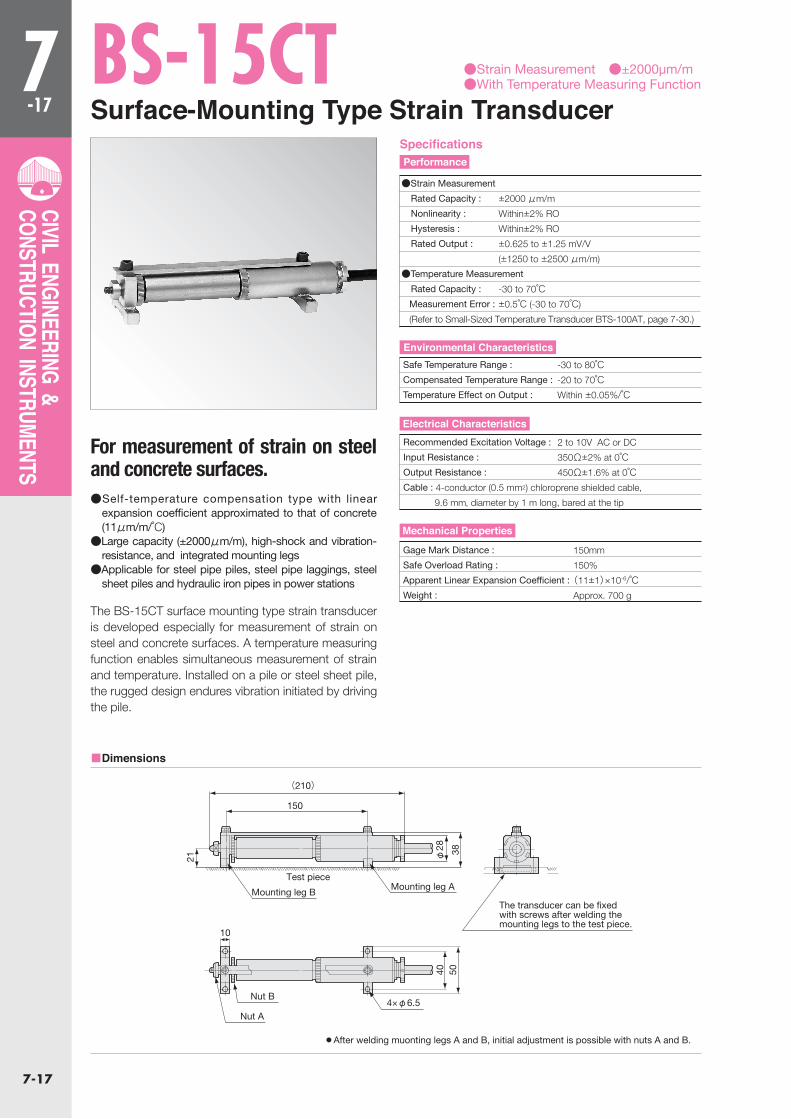
For measurement of strain on steel and concrete surfaces.
The BS-15CT surface mounting type strain transducer is developed especially for measurement of strain on steel and concrete surfaces. A temperature measuring function enables simultaneous measurement of strain and temperature. Installed on a pile or steel sheet pile, the rugged design endures vibration initiated by driving the pile.
●Self-temperature compensation type with linear expansion coefficient approximated to that of concrete (11μm/m/℃)
●Large capacity (±2000μm/m), high-shock and vibration-resistance, and integrated mounting legs
●Applicable for steel pipe piles, steel pipe laggings, steel sheet piles and hydraulic iron pipes in power stations
●Strain Measurement
Rated Capacity : ±2000 μm/m
Nonlinearity : Within±2% RO
Hysteresis : Within±2% RO
Rated Output : ±0.625 to ±1.25 mV/V
(±1250 to ±2500 μm/m)
●Temperature Measurement
Rated Capacity : -30 to 70℃ Measurement Error : ±0.5℃ (-30 to 70℃)
(Refer to Small-Sized Temperature Transducer BTS-100AT, page 7-30.)
Safe Temperature Range : -30 to 80℃Compensated Temperature Range : -20 to 70℃Temperature Effect on Output : Within ±0.05%/℃
Recommended Excitation Voltage : 2 to 10V AC or DC
Input Resistance : 350Ω±2% at 0℃Output Resistance : 450Ω±1.6% at 0℃Cable : 4-conductor (0.5 mm2) chloroprene shielded cable,
9.6 mm,diameter by 1 m long, bared at the tip
Gage Mark Distance : 150mm
Safe Overload Rating : 150%
Apparent Linear Expansion Coefficient : (11±1)×10-6/℃Weight : Approx. 700 g
● After welding muonting legs A and B, initial adjustment is possible with nuts A and B.
SpecificationsPerformance
Environmental Characteristics
Electrical Characteristics
Mechanical Properties
φ28 38
5040
21
150
10
Mounting leg B
Nut B
Nut A
Test pieceMounting leg A
The transducer can be fixedwith screws after welding themounting legs to the test piece.
(210)
4×φ6.5
7-18
7-18
CIVIL ENGINEERING & CONSTRUCTION INSTRUMENTS
Surface-Mounting Type Strain Transducer
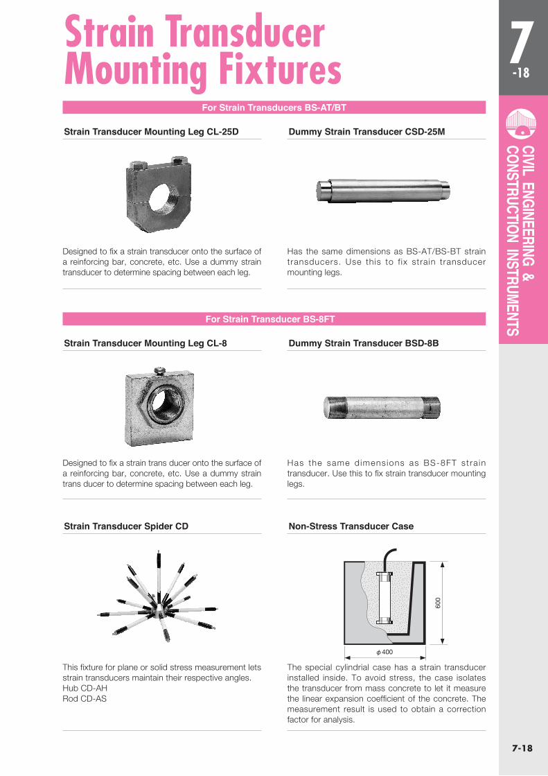
Designed to fix a strain transducer onto the surface of a reinforcing bar, concrete, etc. Use a dummy strain transducer to determine spacing between each leg.
Designed to fix a strain trans ducer onto the surface of a reinforcing bar, concrete, etc. Use a dummy strain trans ducer to determine spacing between each leg.
Has the same dimensions as BS-AT/BS-BT strain transducers. Use this to f ix strain transducer mounting legs.
Has the same d imens ions as BS-8FT st ra in transducer. Use this to fix strain transducer mounting legs.
For Strain Transducers BS-AT/BT
For Strain Transducer BS-8FT
Strain Transducer Mounting Leg CL-25D
Strain Transducer Mounting Leg CL-8
Strain Transducer Spider CD
Dummy Strain Transducer CSD-25M
Dummy Strain Transducer BSD-8B
Non-Stress Transducer Case
This fixture for plane or solid stress measurement lets strain transducers maintain their respective angles.Hub CD-AHRod CD-AS
The special cylindrial case has a strain transducer installed inside. To avoid stress, the case isolates the transducer from mass concrete to let it measure the linear expansion coefficient of the concrete. The measurement result is used to obtain a correction factor for analysis.
Strain Transducer Mounting Fixtures
600
φ400
7-19
7-19
CIVIL ENGINEERING & CONSTRUCTION INSTRUMENTS
BF-CTReinforcing-Bar Stress Transducers
●Stress Measurement ●300 MPa ●With Temperature Measuring Function
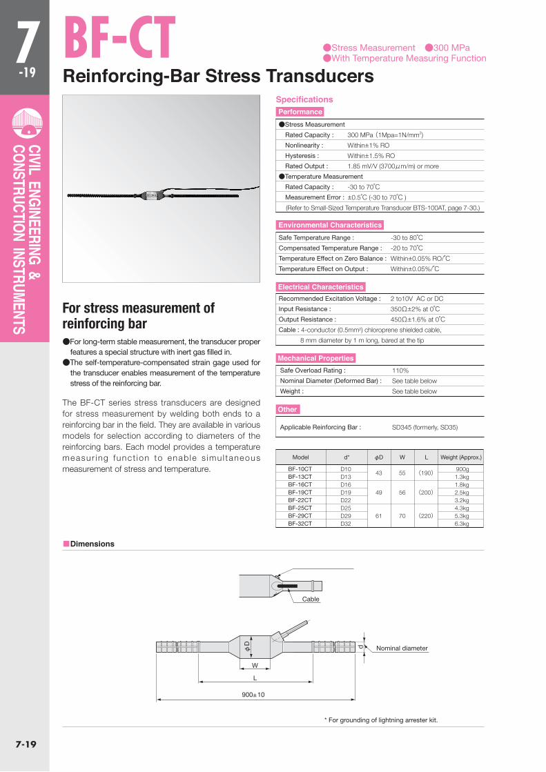
For stress measurement of reinforcing bar
The BF-CT series stress transducers are designed for stress measurement by welding both ends to a reinforcing bar in the field. They are available in various models for selection according to diameters of the reinforcing bars. Each model provides a temperature measur ing funct ion to enab le s imu l taneous measurement of stress and temperature.
●For long-term stable measurement, the transducer proper features a special structure with inert gas filled in.
●The self-temperature-compensated strain gage used for the transducer enables measurement of the temperature stress of the reinforcing bar.
■Dimensions
BF-10CTBF-13CTBF-16CTBF-19CTBF-22CTBF-25CTBF-29CTBF-32CT
D10D13D16D19D22D25D29D32
43
49
61
55
56
70
(190)
(200)
(220)
900g1.3kg1.8kg2.5kg3.2kg4.3kg5.3kg6.3kg
d* φD W L Weight (Approx.)Model
●Stress Measurement
Rated Capacity : 300 MPa (1Mpa=1N/mm2)
Nonlinearity : Within±1% RO
Hysteresis : Within±1.5% RO
Rated Output : 1.85 mV/V (3700μm/m) or more
●Temperature Measurement
Rated Capacity : -30 to 70℃
Measurement Error : ±0.5℃ (-30 to 70℃ )
(Refer to Small-Sized Temperature Transducer BTS-100AT, page 7-30.)
Safe Temperature Range : -30 to 80℃Compensated Temperature Range : -20 to 70℃Temperature Effect on Zero Balance : Within±0.05% RO/℃Temperature Effect on Output : Within±0.05%/℃
Recommended Excitation Voltage : 2 to10V AC or DC
Input Resistance : 350Ω±2% at 0℃Output Resistance : 450Ω±1.6% at 0℃Cable : 4-conductor (0.5mm2) chloroprene shielded cable,
8 mm diameter by 1 m long, bared at the tip
Safe Overload Rating : 110%
Nominal Diameter (Deformed Bar) : See table below
Weight : See table below
Applicable Reinforcing Bar : SD345 (formerly, SD35)
SpecificationsPerformance
Environmental Characteristics
Electrical Characteristics
Mechanical Properties
Other
* For grounding of lightning arrester kit.
d
L
900±10
Nominal diameter
M4 hexagon nut*
Cable
W
φD

7-20
7-20
CIVIL ENGINEERING & CONSTRUCTION INSTRUMENTS
BFD-A-TSReinforcing-Bar Stress Transducers
●Stress Measurement ●300 MPa ●With Temperatare measuring Function
For stress measurement of reinforcing bar
The BFD-A-TS series transducers are designed for stress measurement of reinforcing bars whose nominal diameters are larger than those measured by the BF-CT series. The BFD-A-TS series is used by welding both ends to a reinforcing bar in the field. Select the model suitable for the diameter of the reinforcing bar. Each model provides a temperature measuring function to enable simultaneous measurement of stress and temperature.
●For long-term stable measurement, the transducer proper features a special structure with inert gas filled in.
●The self-temperature-compensated strain gage used for the transducer enables measurement of temperature stress of the reinforcing bar.
BFD-A-35TSBFD-A-38TSBFD-A-41TSBFD-A-51TS
60.563.570.076.3
D35D38D41D51
φA d (Deformed Bar)Model
■Dimensions
●Performance
Rated Capacity : 300 MPa (1Mpa=1N/mm2)
(Please contact sales staff about rated capacity for 350 to 400MPa)
Nonlinearity : Within±1% RO
Hysteresis : Within ±1% RO
Rated Output : 1.85 mV/V (3700 μm/m) or more
●Temperature Measurement
Rated Capacity : -30 to 70℃ Measurement Error : ±0.5℃ (-30 to 70℃)
(Refer to Small-Sized Temperature Transducer BTS-100AT, page 7-30.)
Safe Temperature Range : -30 to 80℃Compensated Temperature Range : -10 to 70℃Temperature Effect on Zero Balance : Within±0.1% RO/C
Temperature Effect on Output : Within±0.1%/℃
Safe Excitation Voltage : 10 V AC or DC
Input Resistance : 350Ω±2% at 0℃Output Resistance : 450Ω±2% at 0℃Cable : 4-conductor (0.5 mm2) chloroprene shielded cable,
8 mm diameter by 1 m long, bared at the tip
Safe Overload Rating : 110%
Nominal Diameter (Deformed Bar) : See table below
Material : Metallic finish
Applicable Reinforcing Bar : SD345 (formerly, SD35)
Reinforcing-Bar : Please provide Reinforcing-Bar for BFD-A-51TS to Kyowa
2 pieces x 335mm long
Calibration : The BFD-A-51TS is calibrated by applying to a single
sensing section, compressive load (approx. 600 kN) equivalent to the
rated capacity of 300 MPa and compressive load (approx. 670 kN)
equivalent to the safe overload rating
SpecificationsPerformance
Environmental Characteristics
Electrical Characteristics
Mechanical Properties
Other
* For grounding of lightning arrester kit.
(20)
φ22
(28)
d
φA
117
(240)
900
Hexagon nut (M4)
Nominal diameter

7-21
7-21
CIVIL ENGINEERING & CONSTRUCTION INSTRUMENTS
BPB-A/BPB-A-TPore Pressure Transducers ●Water Pressure Measurement
●200 kPa to 2 MPa ●With Temperature Measuring Function
Embedded in a boring or together with a pile or steel sheet pile. These transducers measure pore water pressure Recommendable Excitation Voltage.
Embedded in a boring or together with a pile or steel sheet pile, BPB-A/BPB-A-T series transducers measure pore water pressures or pore pressures. If desired, they can be used as pressure-based underground water level transducers by installing in a well. Recommendable Excitation Voltage. The BPB-A-T series is provided with temperature measuring function for simultaneous measurement of pore pressure and temperature. The cable length may be changed as specified.
●Small-sized design, 30 mm in outer diameter, enables installation in borings of small diameters.
●Flat filter (10μm mesh standard) is provided to prevent the sensing part from clogging.
●Stainless steel case (including flat filter FB-10SUS)
■Dimensions
BPF and FB Filters for Pore Pressure Transducers
※Double shielded cable can also be manufactured.
※Filter section is made of brass, sintered metallic finish. ※10μm flat filter only is made of stainless steel.
These filters are used to prevent the sensing portion of the pore pressure transducer which is embedded in clay soil or mud from clogging. The standard mesh size is 10μm. If grouting is made around the embedded site, use the 2 μm mesh filter.
BPF-B FB
FB-2FB-5FB-10SUSFB-40FB-100
2 μm 5 μm 10 μm 40 μm100 μm
Cone Filter Flat Filter Mesh SizeBPF-2BBPF-5BBPF-10B
Pore Pressure Measurement
Rated Capacity : See table below
Nonlinearity : Within±2% RO (BPB-A-200KP)
Within ±1% RO (BPB-A-500KP to 2MP)
Hysteresis : Within ±1% RO
Rated Output : 0.75 mV/V (1500μm/m) or more (BPB-A-200KP)
1 mV/V (2000μm/m) or more (BPB-A-500KP to 2MP)
Temperature Measurement (BPB-A-T)
Rated Capacity : -30 to 70℃ Measurement Error : ±0.5℃ (-30 to 70℃)
(Refer to Small-Sized Temperature Transducer BTS-100AT, page 7-30.)
Safe Temperature Range : 0 to 80℃ (BPB-A) (non-freezing)
-30 to 80℃ (BPB-A-T) (non-freezing)
Compensated Temperature Range : 0 to 60℃ (non-freezing)
Temperature Effect on Zero Balance : Within ±0.1% RO/℃Temperature Effect on Output : Within ±0.1%/℃
Recommendable Excitation Voltage : 2 to 10 V AC or DC
Input Resistance : 350Ω±1% (BPB-A-T at 0℃)
Output Resistance : 350Ω±1% (450Ω±0.8% at 0℃ with BPB-A-T)Cable : 4-conductor (0.5 mm2) chloroprene shielded cable,
11.5 mm diameter by 1 m long, bared at the tip
Safe Overload Rating : 150%
Weight : Approx. 320 g
* For grounding of lightning arrester kit.
SpecificationsPerformance
Environmental Characteristics
Electrical Characteristics
Mechanical Properties
64.5
55.5
(10.5)
(15)
φ30
φ30
φ22
M4 ※R3/4
M4 ※R3/4
107 (15)
(53) 45
φ31
φ30
φ22
BPB-A-200KPBPB-A-500KPBPB-A-1MPBPB-A-2MP
200kPa500kPa
1MPa2MPa
No Yes Rated CapacityTemperature Measuring Function
BPB-A-500KP-TBPB-A-1MP-T
7-22
7-22
CIVIL ENGINEERING & CONSTRUCTION INSTRUMENTS
BPC-APore Pressure Transducers ●Water Pressure Measurement
●200 kPa to 2 MPa
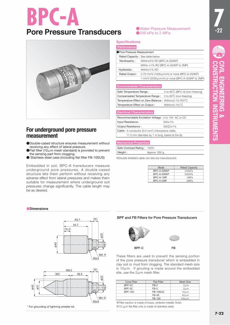
For underground pore pressure measurement
Embedded in soil, BPC-A transducers measure underground pore pressures. A double-cased structure lets them perform without receiving any adverse effect from lateral pressures and makes them suitable for measurement where underground soil pressures change significantly. The cable length may be as desired.
●Double-cased structure ensures measurement without receiving any effect of lateral pressure.
●Flat filter (10μm mesh standard) is provided to prevent the sensing part from clogging.
● Stainless steel case (including flat filter FB-10SUS) ※Double shielded cable can also be manufactured.
BPF and FB Filters for Pore Pressure Transducers
※Filter section is made of brass, sintered metallic finish.※10-μm flat filter only is made of stainless steel.
These filters are used to prevent the sensing portion of the pore pressure transducer which is embedded in clay soil or mud from clogging. The standard mesh size is 10μm. If grouting is made around the embedded site, use the 2μm mesh filter.
BPF-C FB
BPF-2CBPF-5CBPF-10C
FB-2FB-5FB-10SUSFB-40FB-100
2μm 5μm 10μm 40μm100μm
Cone Filter Flat Filter Mesh Size
■Dimensions
●Pore Pressure Measurement
Rated Capacity : See table below
Nonlinearity : Within±2% RO (BPC-A-200KP)
Within ±1% RO (BPC-A-500KP to 2MP)
Hysteresis : Within±1% RO
Rated Output : 0.75 mV/V (1500μm/m) or more (BPC-A-200KP)
1 mV/V (2000μm/m) or more (BPC-A-500KP to 2MP)
Safe Temperature Range : 0 to 80℃ (BPC-A) (non-freezing)
Compensated Temperature Range : 0 to 60℃ (non-freezing)
Temperature Effect on Zero Balance : Within±0.1% RO/℃Temperature Effect on Output : Within±0.1%/℃
Recommendable Excitation Voltage : 2 to 10V AC or DC
Input Resistance : 350±1%
Output Resistance : 350Ω±1%
Cable : 4-conductor (0.5 mm2) chloroprene cable,
11.5 mm diameter by 1 m long, bared at the tip
Safe Overload Rating : 150%
Weight : Approx. 550 g
* For grounding of lightning arrester kit.
SpecificationsPerformance
Environmental Characteristics
Electrical Characteristics
Mechanical Properties
M4 ※R3/4
M4 ※R3/4
63.7 (15)
(15)
54.7
(15.2)
φ40
φ22
φ22
108.5(60) 39.5
φ40
φ31
BPC-A-200KPBPC-A-500KPBPC-A-1MPBPC-A-2MP
200kPa500kPa
1MPa2MPa
Rated CapacityMode

7-23
7-23
CIVIL ENGINEERING & CONSTRUCTION INSTRUMENTS
BPG-A-SHigh-Sensitivity Pore Pressure Transducers
●Water Pressure Measurement ●200 & 500 kPa
Suitable for high sensitivity measurement of underground water level.
Featuring rated output of 4000μm/m, the BPG-A-S series pore pressure transducers provide a sensitivity twice as high as ordinary units. Thus, they are suitable for precise measurement of underground water level etc by embedding in a well, etc.
●High sensitivity (4000μm/m) and high accuracy (±0.5% RO)●Excellent temperature characteristics (±0.02% RO/℃) ●Cone filter attached (possible to replace to a flat filter)
■Dimensions
Note:10μm flat filter stanless steel only
Rated Capacity : BPG-A-200KPS : 200kPa
BPG-A-500KPS : 500kPa
Nonlinearity : Within±0.5% RO
Hysteresis : Within±0.5% RO
Rated Output : 2 mV/V (4000 μm/m) ±2%
Safe Temperature Range : -20 to 70℃ (non-freezing)
Compensated Temperature Range : -10 to 60℃(non-freezing)
Temperature Effect on Zero Balance : Within±0.02% RO/℃
Temperature Effect on Output : Within±0.02%/℃
Input Resistance : 350Ω±1%
Output Resistance : 350Ω±1%
Cable : 4-conductor (0.5 mm2) chloroprene shielded cable,
10 mm diameter by 1 m long, bared at the tip
(Shield is not connected to the mainframe.)
Safe Overload Rating : 120%
Material : Stainless steel metallic finish (filter sintered brass metallic finish
Water Pressure Resistance of Cable Outlet : 240kPa(200KPS) 600kPa(500KPS)Weight : Approx, 800g
SpecificationsPerformance
Environmental Characteristics
Electrical Characteristics
Mechanical Properties
(164)61 55 22
48 8
32(26.5)
60°
φ30
12
φ60
M30×2
φ15
φ18
.5
7-24
7-24
CIVIL ENGINEERING & CONSTRUCTION INSTRUMENTS
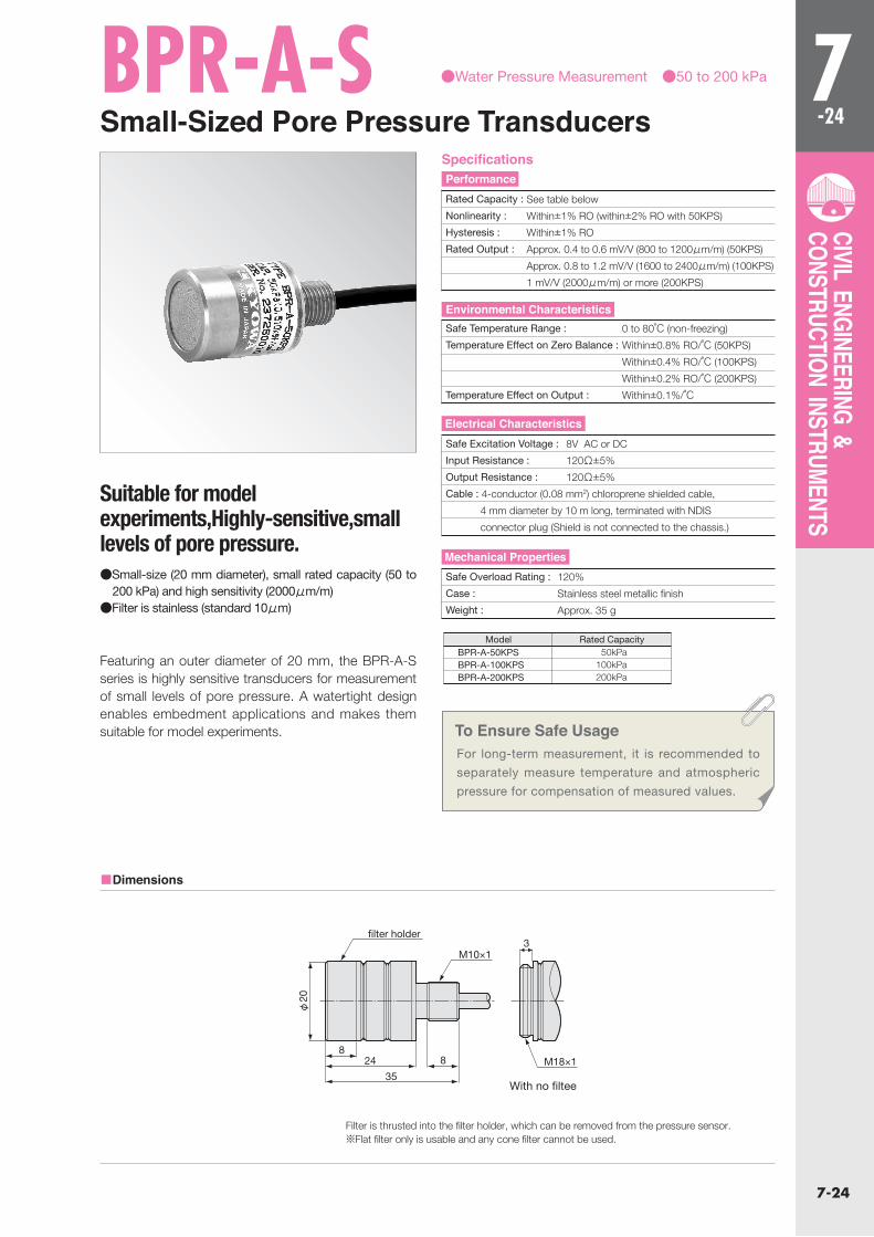
BPR-A-SSmall-Sized Pore Pressure Transducers
●Water Pressure Measurement ●50 to 200 kPa
Suitable for model experiments,Highly-sensitive,small levels of pore pressure.
Featuring an outer diameter of 20 mm, the BPR-A-S series is highly sensitive transducers for measurement of small levels of pore pressure. A watertight design enables embedment applications and makes them suitable for model experiments.
●Small-size (20 mm diameter), small rated capacity (50 to 200 kPa) and high sensitivity (2000μm/m)
●Filter is stainless (standard 10μm)
To Ensure Safe UsageFor long-term measurement, it is recommended to
separately measure temperature and atmospheric
pressure for compensation of measured values.
■Dimensions
Filter is thrusted into the filter holder, which can be removed from the pressure sensor.※Flat filter only is usable and any cone filter cannot be used.
With no filtee
Rated Capacity : See table below
Nonlinearity : Within±1% RO (within±2% RO with 50KPS)
Hysteresis : Within±1% RO
Rated Output : Approx. 0.4 to 0.6 mV/V (800 to 1200μm/m) (50KPS)
Approx. 0.8 to 1.2 mV/V (1600 to 2400μm/m) (100KPS)
1 mV/V (2000μm/m) or more (200KPS)
Safe Temperature Range : 0 to 80℃ (non-freezing)
Temperature Effect on Zero Balance : Within±0.8% RO/℃ (50KPS)
Within±0.4% RO/℃ (100KPS)
Within±0.2% RO/℃ (200KPS)
Temperature Effect on Output : Within±0.1%/℃
Safe Excitation Voltage : 8V AC or DC
Input Resistance : 120Ω±5%
Output Resistance : 120Ω±5%
Cable : 4-conductor (0.08 mm2) chloroprene shielded cable,
4 mm diameter by 10 m long, terminated with NDIS
connector plug (Shield is not connected to the chassis.)
Safe Overload Rating : 120%
Case : Stainless steel metallic finish
Weight : Approx. 35 g
SpecificationsPerformance
Environmental Characteristics
Electrical Characteristics
Mechanical Properties
φ20
M10×1
filter holder
824 8
35
3
M18×1
BPR-A-50KPSBPR-A-100KPSBPR-A-200KPS
50kPa100kPa200kPa
Rated CapacityModel
7-25
7-25
CIVIL ENGINEERING & CONSTRUCTION INSTRUMENTS
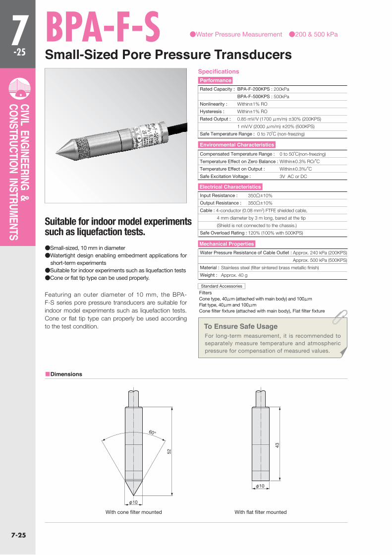
BPA-F-SSmall-Sized Pore Pressure Transducers
●Water Pressure Measurement ●200 & 500 kPa
Suitable for indoor model experiments such as liquefaction tests.
Featuring an outer diameter of 10 mm, the BPA-F-S series pore pressure transducers are suitable for indoor model experiments such as liquefaction tests. Cone or flat tip type can properly be used according to the test condition.
●Small-sized, 10 mm in diameter●Watertight design enabling embedment applications for
short-term experiments●Suitable for indoor experiments such as liquefaction tests●Cone or flat tip type can be used properly.
To Ensure Safe UsageFor long-term measurement, it is recommended to separately measure temperature and atmospheric pressure for compensation of measured values.
FiltersCone type, 40μm (attached with main body) and 100μmFlat type, 40μm and 100μmCone filter fixture (attached with main body), Flat filter fixture
■Dimensions
Rated Capacity : BPA-F-200KPS : 200kPa
BPA-F-500KPS : 500kPa
Nonlinearity : Within±1% RO
Hysteresis : Within±1% RO
Rated Output : 0.85 mV/V (1700 μm/m) ±30% (200KPS)
1 mV/V (2000 μm/m) ±20% (500KPS)
Safe Temperature Range : 0 to 70℃ (non-freezing)
Compensated Temperature Range : 0 to 50℃(non-freezing)
Temperature Effect on Zero Balance : Within±0.3% RO/℃Temperature Effect on Output : Within±0.3%/℃Safe Excitation Voltage : 3V AC or DC
Input Resistance : 350Ω±10%
Output Resistance : 350Ω±10%
Cable : 4-conductor (0.08 mm2) FTFE shielded cable,
4 mm diameter by 3 m long, bared at the tip
(Shield is not connected to the chassis.)
Safe Overload Rating : 120% (100% with 500KPS)
Water Pressure Resistance of Cable Outlet : Approx. 240 kPa (200KPS)
Approx. 500 kPa (500KPS)
Material : Stainless steel (filter sintered brass metallic finish)
Weight : Approx. 40 g
Standard Accessories
With cone filter mounted With flat filter mounted
SpecificationsPerformance
Environmental Characteristics
Electrical Characteristics
Mechanical Properties
60°
52
φ10
43
φ10

7-26
7-26
CIVIL ENGINEERING & CONSTRUCTION INSTRUMENTS
BPT-A-80KPSSoil Moisture Transducer ●Water Pressure Measurement ● -80 kPa
This transducer is suitable for measurement of soil moisture absorbing force and proper for management of plant cultivation
The BPT-A-80KPS is a soil moisture transducer designed to measure water pressure in a vessel equipped with a porous cup (porous ceramic tube) and filled with degassed water. If the soil around the embedded porous cup is dry, the soil absorbs water from the vessel via the porous cup. By measuring this negative pressure (water absorbing pressure), the amount of moisture in the soil is obtained. Thus, this transducer is applicable not only to check for possible landslide or grasp the stability of a banking but also to know changing soil moisture and proper irrigation time in plant caltivation.
■Dimensions
To Ensure Safe UsageThe BPT-A-80KPS is delivered with a vessel filled with degassed water. Never store it unused for a long period of time. Embed it upon purchasing.
Rated Capacity : -80kPa
200 kPa for positive pressure
Nonlineacity : Within±0.5% RO
Hysteresis : Within±0.5% RO
Rated Output : -0.8 mV/V (-1600μm/m) or more
Safe Temperature Range : 0 to 80℃(non-freezing)
Compensated Temperature Range : 0 to 70℃ (non-freezing)
Temperature Effect on Zero Balance : Within±0.05% RO/℃Temperature Effect on Output : Within±0.05%/℃
Safe Excitation Voltage : 10V AC or DC
Input Resistance : 350Ω±2%
Output Resistance : 350Ω±2%
Cable : 4-conductor (0.5 mm2) chloroprene shielded cable,
10 mm diameter by 1 m long, bared at the tip
(Shield is not connected to the chassis.)
Safe Overload Rating : 100%
Case : Stainless steel metallic finish
(excluding porous cup and level meter)
Weight : Approx. 3.5 kg
L=100 to 2000 mm (as specified)
SpecificationsPerformance
Environmental Characteristics
Electrical Characteristics
Mechanical Properties
φ38
Porous cup Extension pipe
Level mete
φ11
6
L H
φ76
.3(φ
21.7)
(φ
22)
(252+L)
(141+L) 74 (37)
(57) (43) L (41)
7-27
7-27
CIVIL ENGINEERING & CONSTRUCTION INSTRUMENTS
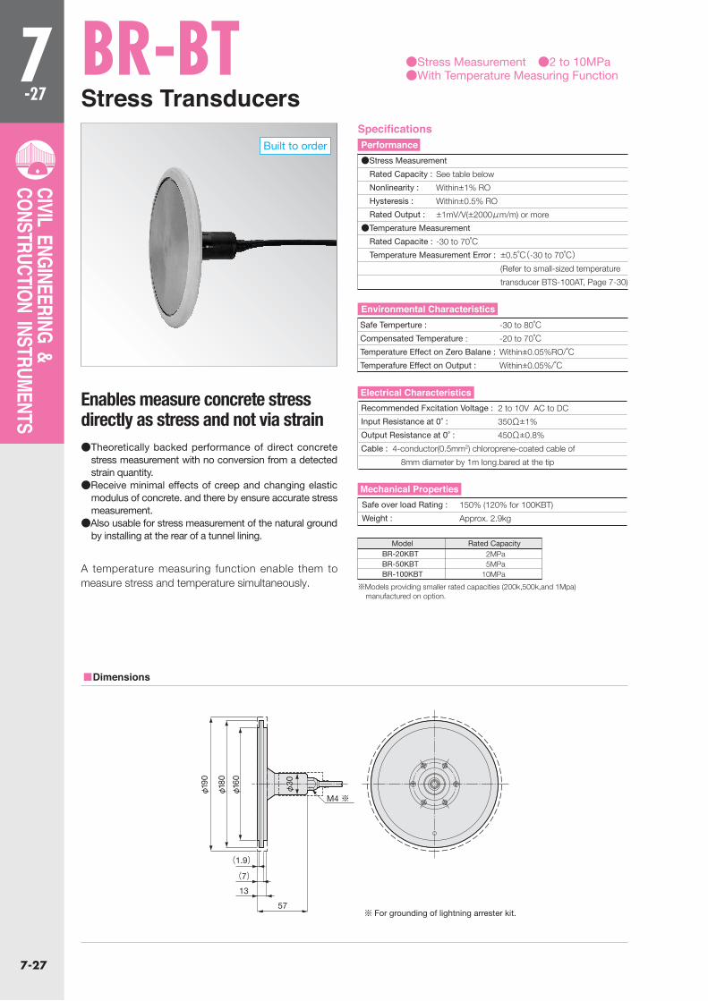
BR-BTStress Transducers
●Stress Measurement ●2 to 10MPa●With Temperature Measuring Function
Enables measure concrete stress directly as stress and not via strain
A temperature measuring function enable them to measure stress and temperature simultaneously.
●Theoretically backed performance of direct concrete stress measurement with no conversion from a detected strain quantity.
●Receive minimal effects of creep and changing elastic modulus of concrete. and there by ensure accurate stress measurement.
●Also usable for stress measurement of the natural ground by installing at the rear of a tunnel lining.
BR-20KBTBR-50KBTBR-100KBT
2MPa5MPa
10MPa
Rated CapacityModel
Built to order
※Models providing smaller rated capacities (200k,500k,and 1Mpa) manufactured on option.
■Dimensions
●Stress Measurement
Rated Capacity : See table below
Nonlinearity : Within±1% RO
Hysteresis : Within±0.5% RO
Rated Output : ±1mV/V(±2000μm/m) or more
●Temperature Measurement
Rated Capacite : -30 to 70℃ Temperature Measurement Error : ±0.5℃(-30 to 70℃) (Refer to small-sized temperature
transducer BTS-100AT, Page 7-30)
Recommended Fxcitation Voltage : 2 to 10V AC to DC
Input Resistance at 0° : 350Ω±1%
Output Resistance at 0° : 450Ω±0.8%
Cable : 4-conductor(0.5mm2) chloroprene-coated cable of
8mm diameter by 1m long.bared at the tip
Safe Temperture : -30 to 80℃Compensated Temperature : -20 to 70℃
Temperature Effect on Zero Balane : Within±0.05%RO/℃Temperafure Effect on Output : Within±0.05%/℃
Safe over load Rating : 150% (120% for 100KBT)
Weight : Approx. 2.9kg
SpecificationsPerformance
Environmental Characteristics
Electrical Characteristics
Mechanical Properties
※ For grounding of lightning arrester kit.
M4 ※
57
13
(7)
(1.9)
φ30
φ16
0
φ18
0
φ19
0
7-28
7-28
CIVIL ENGINEERING & CONSTRUCTION INSTRUMENTS
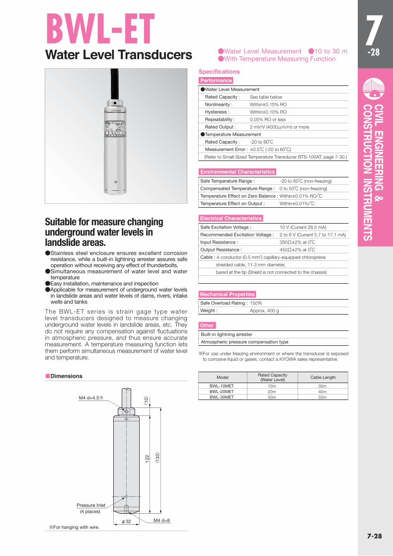
BWL-ETWater Level Transducers ●Water Level Measurement ●10 to 30 m
●With Temperature Measuring Function
Suitable for measure changing underground water levels in landslide areas.
The BWL-ET series is strain gage type water level transducers designed to measure changing underground water levels in landslide areas, etc. They do not require any compensation against fluctuations in atmospheric pressure, and thus ensure accurate measurement. A temperature measuring function lets them perform simultaneous measurement of water level and temperature.
●Stainless steel enclosure ensures excellent corrosion resistance, while a built-in lightning arrester assures safe operation without receiving any effect of thunderbolts.
●Simultaneous measurement of water level and water temperature
●Easy installation, maintenance and inspection ●Applicable for measurement of underground water levels
in landslide areas and water levels of dams, rivers, intake wells and tanks
BWL-10METBWL-20METBWL-30MET
10m20m30m
30m40m50m
Rated Capacity(Water Level) Cable LengthModel
※For use under freezing environment or where the transducer is exposed to corrosive liquid or gases, contact a KYOWA sales representative.
■Dimensions
●Water Level Measurement
Rated Capacity : See table below
Nonlinearity : Within±0.15% RO
Hysteresis : Within±0.10% RO
Repeatability : 0.05% RO or less
Rated Output : 2 mV/V (4000μm/m) or more
●Temperature Measurement
Rated Capacity : -20 to 60℃ Measurement Error : ±0.5℃ (-20 to 60℃)
(Refer to Small-Sized Temperature Transducer BTS-100AT, page 7-30.)
Safe Temperature Range : -20 to 60℃ (non-freezing)
Compensated Temperature Range : 0 to 50℃ (non-freezing)
Temperature Effect on Zero Balance : Within±0.01% RO/℃
Temperature Effect on Output : Within±0.01%/℃
Safe Excitation Voltage : 10 V (Current 28.5 mA)
Recommended Excitation Voltage : 2 to 6 V (Current 5.7 to 17.1 mA)
Input Resistance : 350Ω±2% at 0℃Output Resistance : 450Ω±2% at 0℃Cable : 4-conductor (0.5 mm2) capillary-equipped chloroprene
shielded cable, 11.3 mm diameter,
bared at the tip (Shield is not connected to the chassis)
Safe Overload Rating : 150%Weight : Approx. 400 g
Built-in lightning arrester
Atmospheric pressure compensation type
SpecificationsPerformance
Environmental Characteristics
Electrical Characteristics
Mechanical Properties
Other
※For hanging with wire.
(10)
122
(13
3)
φ32
Pressure Inlet
M4 d=8
M4 d=4.5※
(4 places)
7-29
7-29
CIVIL ENGINEERING & CONSTRUCTION INSTRUMENTS
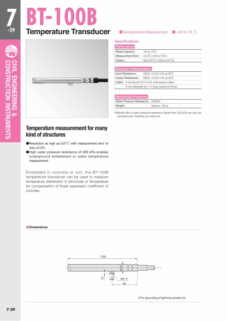
BT-100BTemperature Transducer ●Temperature Measurement ● -30 to 70 ℃
Temperature measurement for many kind of structures
Embedded in concrete or so i l , the BT-100B temperature transducer can be used to measure temperature distribution in structures or temperature for compensation of linear expansion coefficient of concrete.
●Resolution as high as 0.01℃ with measurement error of only ±0.3%
●High water pressure resistance of 200 kPa enables underground embedment or water temperature measurement.
※Model with a water pressure resistance higher than 200 kPa can also be manufactured. Inquiries are welcome.
■Dimensions
Rated Capacity : -30 to 70℃Measurement Error : ±0.3℃ (-30 to 70℃)
Output : 50μV/V/℃ (100μm/m/℃)
Input Resistance : 350Ω +0.3%/-0% at 25℃Output Resistance : 350Ω +0.3%/-0% at 25℃Cable : 4-conductor (0.5 mm2) chloroprene cable,
8 mm diameter by 1 m long, bared at the tip
Water Pressure Resistance : 200kPa
Weight : Approx. 120 g
※For grounding of lightning arrester kit.
SpecificationsPerformance
Electrical Characteristics
Mechanical Properties
(138)
φ12
.5
(5) 10
50
M4 ※
7-30
7-30
CIVIL ENGINEERING & CONSTRUCTION INSTRUMENTS
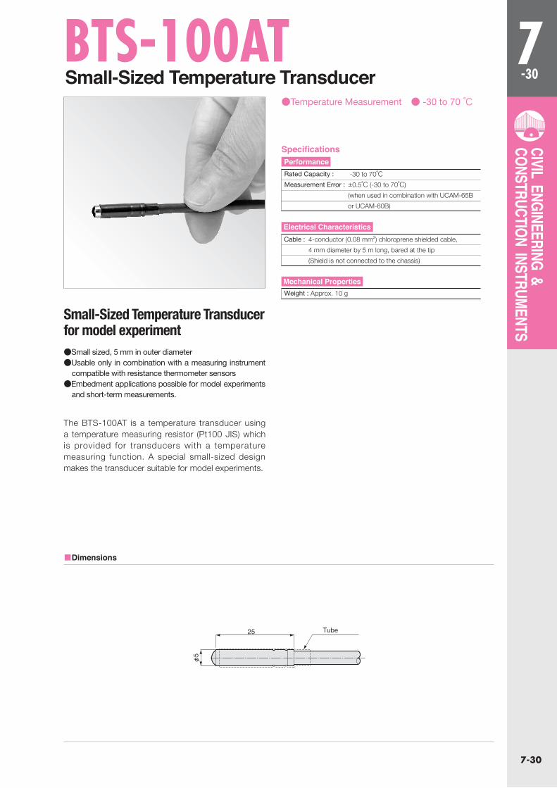
BTS-100ATSmall-Sized Temperature Transducer
●Temperature Measurement ● -30 to 70 ℃
Small-Sized Temperature Transducer for model experiment
The BTS-100AT is a temperature transducer using a temperature measuring resistor (Pt100 JIS) which is provided for transducers with a temperature measuring function. A special small-sized design makes the transducer suitable for model experiments.
●Small sized, 5 mm in outer diameter●Usable only in combination with a measuring instrument
compatible with resistance thermometer sensors●Embedment applications possible for model experiments
and short-term measurements.
■Dimensions
Specifications
Rated Capacity : -30 to 70℃
Measurement Error : ±0.5℃ (-30 to 70℃)
(when used in combination with UCAM-65B
or UCAM-60B)
Performance
Cable : 4-conductor (0.08 mm2) chloroprene shielded cable,
4 mm diameter by 5 m long, bared at the tip
(Shield is not connected to the chassis)
Electrical Characteristics
Weight : Approx. 10 g
Mechanical Properties
25 Tube
φ5

7-31
7-31
CIVIL ENGINEERING & CONSTRUCTION INSTRUMENTS
BJ-ATJoint Transducers
BJ-5AT
CJS-1C
●Displacement Measurement ●5 to 50 mm ●With Temperature Measuring Function
Suitable to check concrete blocks for opening at the joint.
Embedded across a joint of adjoining concrete blocks, the BJ-AT series joint transducers measure an opening between blocks. A temperature measuring function enables simultaneous measurement of displacement and temperature. In addition, for measurement of cracks of concrete or rock-bed, a dedicated receptacle allows embedment in concrete and mounting legs or fixtures enable surface installation.
●Suitable to check concrete blocks for an opening at the joint or cracks initiated mainly by temperature change
●Mounting fixtures are available to measure an opening between a hydraulic pipe and backing concrete, as well as to use them as ordinary displacement transducers to check for deformation of blocks at dam monitoring areas or to detect displacement of rock-bed.
●For embedment in concrete, the dedicated receptacle CJS-1C is embedded in advance in a preceding block and the joint transducer is installed to the next block.
BJ-5ATBJ-10ATBJ-20ATBJ-50AT
5mm10mm20mm50mm
260
260270
275
275285
25
50100
Rated Capacity (Displacement) A (Approx.) B (Approx.)
Bellows (Approx.)Model
Dedicated receptacle CJS-1S
※For surface installation and various mounting fixtures, contact KYOWA sales representative.
※For ordinary displacement transducers, refer to pages 2-133 to 143.
■Dimensions
CJS-1C
●Displacement Measurement
Rated Capacity : See table below
Nonlinearity : Within±1.5% RO
Hysteresis : Within±1.5% RO
Rated Output : 1 mV/V (2000μm/m) or more
●Temperature Measurement
Rated Capacity : -30 to 70℃ Measurement Error : ±0.5 ℃ (-30 to 70℃)
(Refer to Small-Sized Temperature Transducer BTS-100AT, page 7-30.)
Safe Temperature Range : -30 to 80℃
Compensated Temperature Range : -20 to 70℃
Temperature Effect on Zero Balance : Within±0.05% RO/℃
Temperature Effect on Output : Within±0.05%/℃
Recommended Excitation Voltage : 2 to 10V AC or DC
Input Resistance : 350Ω±1% at 0℃Output Resistance : 450Ω±0.8% at 0℃Cable : 4-conductor (0.5 mm2) chloroprene shielded cable,
11.5 mm diameter by 1 m long, bared at the tip
Safe Overload Rating : 120%
Weight : Approx. 790 g
※For grounding of lightning arrester kit.
Optional Accessory
G1/
2
(φ44)
φ22
φ37
M4 ※
Vinyl tapeRubber cover
Bellows
φ30
(60)(A)
(B)
16
φ54
160
2-φ5 through hole
φ10 W=
2 d=
2
110
G1/
2
SpecificationsPerformance
Environmental Characteristics
Electrical Characteristics
Mechanical Properties
7-32
7-32
CIVIL ENGINEERING & CONSTRUCTION INSTRUMENTS
M6M10 P=1.5
φ34 ※ M4×0.7
(275)L
L
40 30
G3/4 G3/4
d=12
Displacement transfer rod (10 mm in outer diameter)
Coupler(male)
Coupler(female)
Long screw (M10)
Hexagon nut (M10)
Displacement adjuster
Displacement adjuster
Long screw (M10)
285 (longest)
Hexagon nut (M10) (x3)
Displacement transfer rod(10 mm in outer diameter)
Coupler (female)Coupler (male)
(x3)
φ48
.6
φ33
L
φ20
M6 ※ M4×0.7
BJB-C-S/D-S/E-S Displacement Transducers
BJB-C-S
BJB-D-S
BJB-E-S
●Displacement Measurement ●50 to 2000 mm
3 models are available for selection of the most suitable one.
The BJB-C-S, BJB-D-S and BJB-E-S ser ies displacement transducers are used as detectors for measurement of rock-bed displacement and ground settlement. Varieties of models are available for selection of the most suitable one based on the measuring range, dimensions and field situations.
●BJB-C-S series is suitable for ordinary measurement of rock-bed displacement.
●BJB-D-S series is available with high rated capacities and is suitable for measurement of the settlement of soft ground.
●Slender BJB-E-S series is suitable for embedment in a boring and for rock-bed displacement measurement in NATM.
BJB-C-100SBJB-C-200SBJB-D-500SBJB-D-1KSBJB-D-2KSBJB-E-50SBJB-E-100S
100mm200mm500mm
1000mm2000mm
50mm100mm
455640
114418593289
417416
With coupler
Used as detector of SVC, SVM, SDD
With coupler
Rated Capacity L (mm) Remarks Model
※ Various mounting fixtures extend the application range. For details, contact a KYOWA sales representative.※ For ordinary displacements, refer to page 2-133 to 143.
■Installation Example
BJB-C-S
BJB-D-S
BJB-E-S
■Dimensions
121
BJB-C-SBJB-D-SBJB-E-S
11.511.5
8
Diameter (mm) Cable Length (m)Model
Rated Capacity : See table below
Nonlinearity : Within±2% RO
Hysteresis : Within±1% RO
Rated Output : 1 mV/V (2000μm/m) or more
Safe Temperature Range : -20 to 70℃Compensated Temperature Range : -10 to 60℃Temperature Effect on Zero Balance : Within±0.1% RO/℃Temperature Effect on Output : Within±0.1%/℃
Recommended Excitation Voltage : 10V AC or DC
Input Resistance : 350Ω±2%
Output Resistance : 350Ω±2%
Cable : 4-conductor (0.5 mm2) chloroprene cable, bared at the tip
Safe Overload Rating : 120% (110% with BJB-D-S)
Measuring Force : Approx. 78 N
※For grounding of lightning arrester kit.
AngleCover
Hexagon nut
Bolt
Movable point
Steady point
DisplacementLong screwCable
SpecificationsPerformance
Environmental Characteristics
Electrical Characteristics
Mechanical Properties
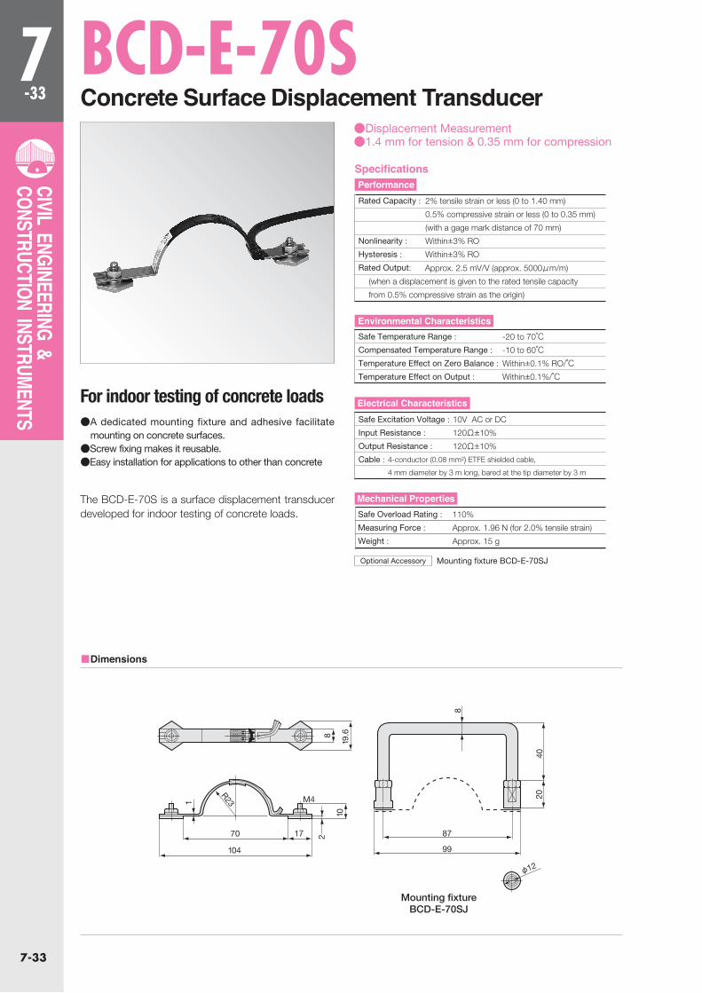
7-33
7-33
CIVIL ENGINEERING & CONSTRUCTION INSTRUMENTS
BCD-E-70SConcrete Surface Displacement Transducer
●Displacement Measurement●1.4 mm for tension & 0.35 mm for compression
For indoor testing of concrete loads
The BCD-E-70S is a surface displacement transducer developed for indoor testing of concrete loads.
●A dedicated mounting fixture and adhesive facilitate mounting on concrete surfaces.
●Screw fixing makes it reusable.●Easy installation for applications to other than concrete
Mounting fixture BCD-E-70SJ
■Dimensions
Rated Capacity : 2% tensile strain or less (0 to 1.40 mm)
0.5% compressive strain or less (0 to 0.35 mm)
(with a gage mark distance of 70 mm)
Nonlinearity : Within±3% RO
Hysteresis : Within±3% RO
Rated Output:
Approx. 2.5 mV/V (approx. 5000μm/m)
(when a displacement is given to the rated tensile capacity
from 0.5% compressive strain as the origin)
Safe Temperature Range : -20 to 70℃
Compensated Temperature Range : -10 to 60℃Temperature Effect on Zero Balance : Within±0.1% RO/℃Temperature Effect on Output : Within±0.1%/℃
Safe Excitation Voltage : 10V AC or DC
Input Resistance : 120Ω±10%
Output Resistance : 120Ω±10%
Cable : 4-conductor (0.08 mm2) ETFE shielded cable,
4 mm diameter by 3 m long, bared at the tip diameter by 3 m
Safe Overload Rating : 110%
Measuring Force : Approx. 1.96 N (for 2.0% tensile strain)
Weight : Approx. 15 g
Optional Accessory
SpecificationsPerformance
Environmental Characteristics
Electrical Characteristics
Mechanical Properties
Mounting fixtureBCD-E-70SJ
8
2040
87
φ12
99
17
M4
70
R23
104
1019
.682
1

7-34
7-34
CIVIL ENGINEERING & CONSTRUCTION INSTRUMENTS
BCD-5BCrack Displacement Transducer
●Displacement Measurement●±5 mm
Easy to install even on a weak rock-bed for accurate measurement.
The BCD-5B crack displacement transducer is designed to measure cracks occurring in concrete structures and rock-beds of mines and quarries. Conventional crack displacement transducers have large measuring force and cannot ensure high measuring accuracy unless mounted sturdily. Furthermore, they are difficult to install on a weak rock-bed. By contrast, the BCD-5B provides an extremely small measuring force and is easy to install even on a weak rock-bed for accurate measurement.
■Dimensions
Rated Capacity : ±5 mm
Nonlinearity : Within±2% RO
Hysteresis : Within±2% RO
Repeatability : 2% RO or less
Rated Output : ±1 mV/V (±2000μm/m)±5%
Safe Temperature Range : -10 to 60℃
Recommended Excitation Voltage : 2 to 10V AC or DC
Input Resistance : 350Ω±2%
Output Resistance : 350Ω±2%
Cable : 4-conductor (0.3mm2) chloroprene shielded cable,
7.6 mm diameter by 1 m long,
bared at the tip (Shield is not connected to the chassis)
Safe Overload Rating : 150%
Measuring Force : Approx. 9.8 N/5 mm
Weight : Approx. 450 g
SpecificationsPerformance
Environmental Characteristics
Electrical Characteristics
Mechanical Properties
3022
80
115
(300)
(95) (44)
90
104.5
80
(35)
(27)
(51)
14 2.6
10.5

7-35
7-35
CIVIL ENGINEERING & CONSTRUCTION INSTRUMENTS
DTP-E-SDrip Proof Large-Capacity Displacement Transducers
●Displacement Measurement ●500 to 2000mm
Suitable for large displacement by dripproof structure
The DTP-E-S ser ies are potent iometer-based transducers for measurement of large displacement.A dripproof structure enables applications where they may be splashed with water or involving highly humid environment.
●Displacement measurement by expansion and contraction (winding)of wire
●Compact size and low measuring force.●Connectable to strain amplifier for measurement ●Resolution Approx.1/1850
■Displacement
■Displacement
DTP-E-500S
DTP-E-500S
To ensure Safe Usage This Transducer cannot be used for a dynamic
measurement,a measurement object with rapid
movement and a micro vibration.
DTP-E-500SDTP-E-1KSDTP-E-2KS
500mm1000mm2000mm
9.8N
4.9N
Rated Capacity Measuring force (Approx)Model
Rated Capacity : See table below
Nonlinearity : Within±1% RO
Hysteresis : Within±1% RO
Rated Output : Approx : 5mV/V(10000μm/V)
Resolution : 1/1850
Detection Method : Potentiometer based
Safe Excitation Voltage : 10V AC or DC
Recommended Rxcitantion Voltage : 1 to 5 V AC or DC
Input Resistance : 350Ω±5%
Dutput Resistance : 350Ω±5%
Cable : 4-conductor(0.5mm2 shielded chloroprehe-coated cable
of lomm diameter by 3m long
bare at the tip (Shield is not connected to the chassis)
Safe Overload Rating : 120%
Measuring Force : See table below
Cycling life : 104 times
Degree of Protection : IP67 dripproofin conformity to JIS(C0920)
Enclolsure : Stainless
Operating Temperature Range : -10 to 60℃
SpecificationsPerformance
Environmental Characteristics
Electrical Characteristics
Mechanical Properties
(14
2)φ
140 Sensitlvity direction
(52)
Stainless wire
(30)
(φ26
.5)
4-φ9Driling hole
144
120
140160
Displacement
moving point
Jack
wire
Immovable point
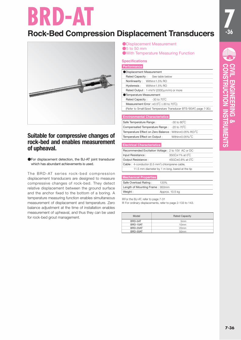
7-36
7-36
CIVIL ENGINEERING & CONSTRUCTION INSTRUMENTS
BRD-ATRock-Bed Compression Displacement Transducers
●Displacement Measurement●5 to 50 mm●With Temperature Measuring Function
Suitable for compressive changes of rock-bed and enables measurement of upheaval.
The BRD-AT se r i es rock -bed compress ion displacement transducers are designed to measure compressive changes of rock-bed. They detect relative displacement between the ground surface and the anchor fixed to the bottom of a boring. A temperature measuring function enables simultaneous measurement of displacement and temperature. Zero balance adjustment at the time of installation enables measurement of upheaval, and thus they can be used for rock-bed grout management.
●For displacement detection, the BJ-AT joint transducer which has abundant achievements is used.
BRD-5ATBRD-10ATBRD-20ATBRD-50AT
5mm10mm20mm50mm
Rated CapacityModel
※For the BJ-AT, refer to page 7-31※ For ordinary displacements, refer to page 2-133 to 143.
●Displacement Measurement
Rated Capacity : See table below
Nonlinearity : Within±1.5% RO
Hysteresis : Within±1.5% RO
Rated Output : 1 mV/V (2000μm/m) or more
●Temperature Measurement
Rated Capacity : -30 to 70℃ Measurement Error : ±0.5℃ (-30 to 70℃)
(Refer to Small-Sized Temperature Transducer BTS-100AT, page 7-30.)
Safe Temperature Range : -30 to 80℃Compensated Temperature Range : -20 to 70℃Temperature Effect on Zero Balance : Within±0.05% RO/℃Temperature Effect on Output : Within±0.05%/℃
Recommended Excitation Voltage : 2 to 10V AC or DC
Input Resistance : 350Ω±1% at 0℃Output Resistance : 450Ω±0.8% at 0℃Cable : 4-conductor (0.5 mm2) chloroprene cable,
11.5 mm diameter by 1 m long, bared at the tip
Safe Overload Rating : 120%
Length of Mounting Frame : 950mm
Weight : Approx. 10.5 kg
SpecificationsPerformance
Environmental Characteristics
Electrical Characteristics
Mechanical Properties

7-37
7-37
CIVIL ENGINEERING & CONSTRUCTION INSTRUMENTS
φ200 (34)φ180φ170φ160
φ25
M4 ※
Effective sensing diameter
Carrying handle
Carrying handle
8-φ8.4 Mounting hole
Effe
ctiv
e se
nsin
g di
amet
er
3.5
25
22.5
(20)
φ22
φ186
M4 ※At optional position
At optional position
φ22
37 (14)
φ30
25
18
φ20
0φ
170
φ16
0
BEE-A/BEF-ASoil Pressure Transducers
BEF-A
BEF-A
BEE-A
BEE-A
●Pressure Measurement ●200 kPa to 2 MPa
A pressure-sensing surface 160mm in diameter,used most popularly in measuring fields.
The BEE-A and BEF-A series are soil pressure transducers with an outer diameter of 200 mm which are used most popularly in measuring fields. The BEE-A series for underground soil pressure measurement is embedded in a core zone of a rockfill dam or ordinary banking. The BEE-A series can also measure soil pressure of 3 or 4face objects. The BEF-A series can be used for soil pressure measurement of a continuous underground earth retaining wall.
●Applied pressure causes minimal diaphragm displacement thanks to a dual diaphragm design.
●Highly accurate displacement ratio of the pressure-sensing surface to its diameter is less than 1/100,000.
●Can measure dynamic soil pressure caused by earthquake, etc.
■Dimensions
Rated : See table below Capacity:
Nonlinearity : Within±1% RO (BEE/BEF-500KP to 2MP)
Within±3% RO (BEE/BEF-A-200KP)
Hysteresis : Within±1% RO
Rated Output : 1 mV/V (2000μm/m) or more(BEE/BEF-500KP to 2MP)
0.9 mV/V (1800μm/m)or more (BEE/BEF-A-200KP)
Safe Temperature Range : -20 to 80℃Compensated Temperature Range : -15 to 70℃Temperature Effect on Zero Balance : Within±0.1% RO/℃Temperature Effect on Output : Within±0.1%/℃
Recommended Excitation Voltage : 2 to 10V AC or DC
Input Resistance : 350Ω±1%
Output Resistance : 350Ω±1%
Cable : 4-conductor (0.5 mm2) chloroprene cable,
11.5 mm diameter by 1 m long, bared at the tip
Safe Overload Rating : 120%
Weight : Approx. 6 kg (BEE-A) Approx. 5.7 kg (BEF-A)
※For grounding of lightning arrester kit.
SpecificationsPerformance
Environmental Characteristics
Electrical Characteristics
Mechanical Properties
BEE-A-200KPBEE-A-500KPBEE-A-1MPBEE-A-2MPBEF-A-200KPBEF-A-500KPBEF-A-1MPBEF-A-2MP
200kPa500kPa
1MPa2MPa
200kPa500kPa
1MPa2MPa
Underground soil pressuremeasurement
Wall surfacesoil pressuremeasurement
Rated Capacity UseModel

7-38
7-38
CIVIL ENGINEERING & CONSTRUCTION INSTRUMENTS
BEM-ASoil Pressure Transducers ●Pressure Measurement ●50 kPa to 1 MPa
A pressure-sensing surface 80mm in diameter.The stainless steel design enables marine applications.
The BEM-A series is underground soil pressure transducers with a pressure-sensing surface 80 mm in diameter. The strainless steel design enables marine applications.
●Dual diaphragm design with the pressure medium sealed between the pressure-sensing surface and strain gage-bonded diaphragm enables transmission of minute displacement through enlargement.
●Stainless steel construction
■Dimensions
To Ensure Safe UsageAvoid installation onto a wall surface.
※For grounding of lightning arrester kit.
Specifications
Rated Capacity : See table below
Nonlinearity : Within±2% RO (BEM-A-50KP to 200KP)
Within 1% RO (BEM-A-500KP & 1MP)
Hysteresis : Within±1% RO
Rated Output : 0.25 mV/V (500μm/m) or more (BEM-A-50KP)
0.5 mV/V (1000μm/m) or more (BEM-A-100KP)
1 mV/V (2000μm/n) or more (BEM-A-200KP to 1MP)
Performance
Safe Temperature Range : -20 to 80℃Compensated Temperature Range : -15 to 70℃Temperature Effect on Zero Balance:
Within±0.5% RO/℃ (BEM-A-50KP)
Within±0.3% RO/℃ (BEM-A-100KP & 200KP)
Within±0.2% RO/℃ (BEM-A-500KP & 1MP)
Temperature Effect on Output : Within±0.1%/℃
Environmental Characteristics
Safe Excitation Voltage : 10V AC or DC
Recommended Excitation Voltage : 2 to 8V AC or DC
Input Resistance : 350Ω±1%
Output Resistance : 350Ω±1%
Cable : 4-conductor (0.5 mm2) chloroprene cable, 8 mm diameter by
1 m long, bared at the tip
Electrical Characteristics
Safe Overload Rating : 120%
Weight : Approx. 1 kg
Mechanical Properties
φ94 (43)φ80
M4 ※
(Pressure sensing surface)
φ1
8
18.2
(16
.7)
9
At optional position
3-M4x5(At equal distance by 120°)
BEM-A-50KPBEM-A-100KPBEM-A-200KPBEM-A-500KPBEM-A-1MP
50kPa100kPa200kPa500kPa
1MPa
Rated CapacityModel

7-39
7-39
CIVIL ENGINEERING & CONSTRUCTION INSTRUMENTS
BEN-ASoil Pressure Transducers
●Pressure Measurement ●500 kPa & 1 MPa
A pressure-sensing surface 70mm in diameter.Vibration-resistant design for installation on driven materials
The BEN-A series soil pressure transducers are specially designed to endure vibrations. Thus, they are suitable for installation on driven materials such as sheet piles and steel pipe piles.
●Dual diaphragm design, with the pressure medium sealed between the pressure-sensing surface and strain gage-bonded diaphragm, enables transmission of minute displacement through enlargement.
●Vibration-resistant design for installation on driven materials
●Highly wear-resistant pressure sensing surface
■Dimensions
Rated Capacity : BEN-A-500KP : 500kPa
BEN-A-1MP : 1MPa
Nonlinearity : Within±1% RO
Hysteresis : Within±1% RO
Rated Output : 1 mV/V (2000μm/n) or more
Safe Temperature Range : -20 to 80℃Compensated Temperature Range : -10 to 50℃Temperature Effect on Zero Balance : Within±0.4% RO/℃ (BEN-A-500KP)
Within±0.2% RO/℃ (BEN-A-1MP)
Temperature Effect on Output : Within±0.2%/℃ (BEN-A-500KP)
Within±0.1%/℃ (BEN-A-1MP)
Safe Excitation Voltage : 10V AC or DC
Recommended Excitation Voltage : 2 to 8V AC or DC
Input Resistance : 350Ω±1%
Output Resistance : 350Ω±1%
Cable : 4-conductor (0.5 mm2) chloroprene cable,
8 mm diameter by 1 m long, bared at the tip
Safe Overload Rating : 150%
Weight : Approx. 1 kg
SpecificationsPerformance
Environmental Characteristics
Electrical Characteristics
Mechanical Properties
φ98φ91φ85φ82φ70
38.4
18.5
13 7
7
15
φ30φ58φ74φ80
6(
10.9)
96
φ18
φ12
96
17 (16)(20)
Protection tube(φ10)
4-M6×8(At equal distance by 120°)

7-40
7-40
CIVIL ENGINEERING & CONSTRUCTION INSTRUMENTS
BEG-A-SLarge-Sized Soil Pressure Transducers
●Pressure Measurement ●200 kPa to 2 MPa
Suitable for soil pressure measurement of rock-fill dams
The BEG-A-S series soil pressure transducers are designed for soil pressure measurement of a banking containing large aggregates. This series is used mainly for soil pressure measurement of rock-fill dams containing large aggregates.
* Asterisked specifications are for the single pressure transducer proper.
■Dimensions
Rated Capacity : See table below
Nonlinearity*: Within±2% RO (BEG-A-200KPS)
Within±1% RO (BEG-A-500KPS to 2MPS)
Hysteresis* : Within±1% RO
Rated Output* : 1mV/V(2000μm/m) or more
0.75mV/V(1500μm/m) or more (BEG-A-200KPS)
Safe Temperature Range : -20 to 80℃Compensated Temperature Range : -10 to 70℃
Temperature Effect on Zero Balance* : Within±0.1% RO/℃Temperature Effect on Output* : Within ±0.1%/℃
Safe Excitation Voltage : 10V AC or DC
Input Resistance : 350Ω±2%
Output Resistance : 350Ω±2%
Cable : 4-conductor (0.5 mm2) chloroprene shielded cable,
11 mm diameter by 2 m long, bared at the tip
Safe Overload Rating : 120%
Material : Corrosion-proof painting on whole surface
SpecificationsPerformance
Environmental Characteristics
Electrical Characteristics
Mechanical Properties
BEG-A-200KPSBEG-A-500KPSBEG-A-1MPSBEG-A-2MPS
200kPa500kPa
1MPa2MPa
Rated CapacityModel
(45
°)
270
200
(65°)
85
20
φ600
Pressuretransducer

7-41
7-41
CIVIL ENGINEERING & CONSTRUCTION INSTRUMENTS
BEC-A/BED-ASmall-Sized Soil Pressure Transducers
BEC-A
BED-A
●Pressure Measurement●200 kPa to 1 MPa
A pressure-sensing surface 23mm in diameter.Suitable for measurement fo soil pressure distribution in short-term or model experiment
The BEC-A and BED-A series are small-sized soil pressure transducers having an outer diameter of 30 mm and a pressure-sensing surface diameter of 27 mm. They are used for measurement of soil pressure distribution in short-term or model experiments.
●Suitable for short-term experiments
■Dimensions
BEC-A BED-A
Rated Capacity : See table below
Nonlinearity : Within±2% RO
Hysteresis : Within±1% RO
Rated Output : 0.25 mV/V (500μm/m) or more
Safe Temperature Range : -10 to 60℃Temperature Effect on Zero Balance : Within±0.4% RO/℃Temperature Effect on Output : Within±0.4%/℃
Recommended Excitation Voltage : 2 to 4V AC or DC
Input Resistance : 120Ω±1.7%
Output Resistance : 120Ω±1.7%
Cable : 4-conductor (0.08 mm2) chloroprene shielded cable,
4 mm diameter by 3 m long,
bared at the tip (Shield is not connected to the chassis)
Safe Overload Rating : 120%
Weight : Approx. 120 g
SpecificationsPerformance
Environmental Characteristics
Electrical Characteristics
Mechanical Properties
φ30
φ23
A B
C
(φ6
)
(52)
φ30φ
23
D
A
(φ12
)( φ
6 ) Protection tube
Protection tube
B(C)
BEC-A-200KPBEC-A-500KPBEC-A-1MP
8.7
9
6.2
6.5
0.5
0.8
A B CModelBED-A-200KPBED-A-500KPBED-A-1MP
6.2
6.5
8.7
9
29.7
30
0.5
0.8
A B C DModel
BEC-A-200KPBEC-A-500KPBEC-A-1MPBED-A-200KPBED-A-500KPBED-A-1MP
200kPa500kPa
1MPa200kPa500kPa
1MPa
Undergroundsoil pressuremeasurement
Wall surfacesoil pressuremeasurement
Rated Capacity UseModel

7-42
7-42
CIVIL ENGINEERING & CONSTRUCTION INSTRUMENTS
BER-A-110SWall-Surface Soil Pressure Transducers
●Pressure Measurement●100 kPa to 2 MPa
Stainless steel models can be manufactured for wave pressure measurement.
The BER-A-110S soil pressure transducers come with the cable attached in parallel to the pressure-sensing surface
●Wear of the pressure sensing surface does not affect output or initial values.
●Load cell-based design is less affected by bending effects.
●Usable for pressure measurement of coal or grain in a silo●For pressure measurement of pulverulent bodies of
approximately 15 mm in diameter
BER-A-100KP110SBER-A-200KP110SBER-A-500KP110SBER-A-1MP110SBER-A-2MP110S
850N1.701kN4.253kN8.506kN17.01kN
100kPa200kPa500kPa
1MPa2MPa
Rated Cabacity Mar lo`adModel
※ Can optionally be coated with anti-biofouling paint.
■Dimensions
To Ensure Safe UsageDo not apply to the pressure sensing surface any load
exceeding the maximum load stated in table above.
Rated Capacity : See table below
Nonlinearity : Within±1% RO
Hysteresis : Within±1% RO
Rated Output : 1 mV/V (2000μm/m) or more
Safe Temperature Range : -30 to 80℃Compensated Temperature Range : 0 to 70℃Temperature Effect on Zero Balance : Within±0.1% RO/℃Temperature Effect on Output : Within±0.1%/℃
Safe Excitation Voltage : 10V AC or DC
Recommended Excitation Voltage : 1 to 5V AC or DC
Input Resistance : 350Ω±2%
Output Resistance : 350Ω±2%
Cable : 4-conductor (0.5 mm2) chloroprene shielded cable,
10 mm diameter by 1 m long, bared at the tip
(Shield is not connected to the chassis.)
Safe Overload Rating : 120%
Maximum Load : See table below
Pressure Sensing Surface Diameter : Approx. 95 mm
Material : Stainless steel metallic finish (pressure sensing surface)
ZnC-plated MF (flange and cable outlet)
Water Pressure Resistance of Cable Outlet : 600 kPa
Weight : Approx. 2.2 kg
SpecificationsPerformance
Environmental Characteristics
Electrical Characteristics
Mechanical Properties
φ100
φ110
6-M6d=9
25
(10)
φ23
36
24

7-43
7-43
CIVIL ENGINEERING & CONSTRUCTION INSTRUMENTS
Civil Engineering Measuring Instrument Selection Chart
Model Features Power Supply Ref page Interface to external
Applicable Sensors (for Civil Engineering)
Number of Measuring Channels
(in combination with scanners)
3-26
7-447-46
3-62
3-44
Data logger
Memory Recorder/Analyzer
Portable Data Recorder
UCAM-60BUCAM-65B
30(Max1000)
1
10
4-slot:Max32channels8-slot:Max64channels
All-in-one Setting,measurement,display and printout on the single unit(60B)
LANRS-232C
RMH-301BUSBmemoryUSB InterfaceRMH-210A M10Flash ATA cardRS-232C
LAN USB memory
Dedicated interface (CAN equivalent)
SD card
SS size dry cell※SME-31A Usable to AC adapter
AC100 to 120V, AC190 to 240V, DC10 to 30V (AC/DC operation)
Dedicated battery
AC85 to 264V(AC version)DC10 to 16V (DC version)
Constant current excitationThe data acguisition of a long term by unattended possibleSaving data to PC from ATA card by USB Interface
Real-time measurement,monitoring,recording & processing possible
Easy to usePortable type
Strain gage
Strain gage transducer
Strain gage civilengineering transducer
Civil engineering transducer with temp meas function
DC voltage-output sensor
DC current-output sensor(UCAM-60B, 65B)
Thermocouple
Resistance thermometer sensor
Potentiometer sensor(UCAM-60B, 65B)
EDX depends on selection of conditioner card.
1
Strain gage
Strain gage transducers
Civil engineering transducer with tempmeas function
RMH-301BRMH-210A M10
EDX-2000B
SME-30A/31A
3-39
Network Terminal Boxes
DC11 to 16V
Easy softwareenables quick measurement
4(Max 32)
Strain gage
Strain gage transducer
Civil engineering transducer
with tempmeas function
DC voltage-output sensor
Thermocouple
NTB-100A SeriesNTB-201A
NTB-101A-350
NTB-201A
NTB-100A-120
Digital Strain Recorder
RMH-210A M10
RMH-301B

7-44
7-44
CIVIL ENGINEERING & CONSTRUCTION INSTRUMENTS
Digital Strain Recorder ●Collected saving date by USB memory
Most suitable for long-term measurement in the absence of personnel under the environment without external power supply
Digital strain recorder RMH-301B is a battery-powered data collection device with low power consumption, suitable for long-tem measurement in the absence of personnel at the places without external power supply such as long-distance mountainous and heavy-snowfall area.Enables to Strain gage civil engineering transducers and civil engineering transducers with tempmeas function and of single-channel measurement.Equipped with operation panel and display enables operation relating to measuring condition setting and measurement.Data can be collected via USB memory. Data can be easily reclaimed at site just by inserting USB disk. In addition to original forms, data can be saved in CSV format.The optional software (RMH-390A) can be used to control computers and collect data through USB interface.
●Small and lightweight●Equipped with a display used to confirm setting
conditions and measured values●Easy to collect data by USB memory
RMH-301BSpecifications■Overall operation
Operating temperature range : -20 to 50℃Operating humidity range : 10 to 95%RH (no-condensing)Operating environment : No external interference caused by grime and large-capacity motors, etc.Dimensions : 112(W)×28(H)×66.5(D)mm (excluding protrusions)Weight : Approx 180 g
■Hard wareNumber of Measuring Channel : 1Measuring object : Strain gage transducer Strain gage civil engineering transducer Civil engineering transducer with tempmeas functionRange of used bridge resistance : 350Ω (4 strain gage method)Cable length : 0.5mm2 4-conductor shielded cable maximum 2.0kmStrain rate : Fixed 2.00Bridge current : Approx DC2.19mA (constant current)Temperature measurement current : DC0.24mA (constant current)Measuring range : Strain capacity :±20000μm/m Temperature :-30.0 to+70.0℃Resolution : Strain capacity : 1×10⁻⁶(μm/m) Temperature : 0.1℃Measuring accuracy : Strain capacity : ±0.1%FS Temperature : ±0.5℃Data storage : Strain capacity : 30720 times Temperature : 30720 times Strain + temperature:20475 timesClock : Year (2 digits of the Gregorian calendar), Month, Date,Hour,MinuteMeasuring interval : 1 to 59 minute (with 1 minute as the unit) 1 to 99 hour (with 1 hour as the unit)Display : LCD (16 digits×2 lines)Operation : Arrow keys, ON/OFF,SET,ESCInterface : USB1.1Power supply : DC6 to 15VCurrent consumption : 100mA during operation and below 100μA under standby statusInput specifications : M3 bolt suitable to crimp terminal RAV, 1.25-3 equivalents
■Control software (RMH-390A) optional accessoriesSetting function : Setting of data collection conditions (measuring name, measuring point number, final measuring channel) setting of channel conditions (transducer name, measuring point mode, initial value, calibration factor and unit)Collection function : Measurement start (measurement start time, interval measurement time and measurement times) Measurement stop Data collection (USB, RS-232C) (measuring data is automatically saved as data collection pass)USB storage function : Entering measuring conditions Data collectionData display : Initial data display/physical quantity display value display (display channel and display period setting) Time series chart display (maximum 3 charts· display channel· display period setting, line type and color selection, automatic and calibration) Print (printer printing documents)Data editing : Measuring data editing (editing of title and data parts)Data conversion : Converted to ASCⅡ formatCheck function : Self diagnosis of measurer (inspection of A-D, cell voltage, transducer and ROM/RAM) test measurement real-time monitoringOthers : Address book setting, Communications condition setting, Time setting and Help function

7-45
7-45
CIVIL ENGINEERING & CONSTRUCTION INSTRUMENTS ■Dimension drawing
Battery pack RB-5A(5Ah) RB-10A(10Ah)
■Operating environment OS : Microsoft Windows (32bit, Japanese version)
2000 Professional XP Home Edition XP Professional VistaInterface : USB Interface (RMH-301B) CD-ROM or DVD (for software installation)CPU : PentiumⅢ, 1GHz or higherMemory required : RAM 512MB or moreHard disk : Hard disk capacity or more 20MB (for installation, excluding that for data) spare capacity or more 10MB (excluding that for saving measuring data)Graphic : High resolution video or more Super VGA (800×600) adaptor and monitor or more 1024×768, or more full-colorOthers : Keyboard and Microsoft Mouse or interchangeable pointing device
DIGITAL STRAIN RECORDER RMH-301B
MODEDISPLAY
AB
ESC SETON/OFF
R W
B G
S
28 (14.66) 112
66.5
Optional Accessories
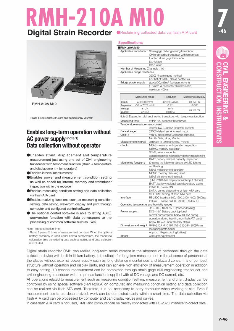
7-46
7-46
CIVIL ENGINEERING & CONSTRUCTION INSTRUMENTS
■RMH-210A M10Applicable transducer : Strain gage civil engineering transducer Civil engineering transducer with tempmeas function strain gage transducer DC voltage DC currentNumber of Measuring Channels : 10Applicable bridge resistance : 350Ω (4 strain gage method) For that of 120Ω, please contact us.Bridge power supply : about DC2.85mA (constant current) (0.5mm2 4-conductor shielded cable, maximum 400m)
Measuring time : Within 120 seconds/10 channelsTemperature measurement current : Approx DC 0.285mA (constant current)Data storage 24000 data/channel for each inputClock : Year (2 digits of the Gregorian calendar), Month, Date, Hour, MinuteMeasurement interval 3 minute to 99 hour and 59 minutecheck : MEAS measurement operation inspection MEMO, memory inspection SENS, sensor inspection (parallel resistance method during strain measurement) BATT battery residual quantity inspectionMonitoring function : Showing the following content by LED lighting and flashing MEAS measurement operation MEMO memory checking result MEAS sensor checking result (RMH-210A has display for each input channel) BATT, battery residual quantity/battery alarm POWER, power ON DATA, during datasaving of flash ATA card SET RMH setting of flash ATA cardInterface : RS-232C baud rate 600, 1200, 2400, 4800, 9600bps PC slot based on PC CARD STANDARDOperating temperature and humidity ranges : -20~50℃, 10~95%RH (noncondensing)Power supply : DC6~15V Battery pack (optional) current consumption below 100mA during operation (during inserting non-flash ATA card) below 100μA under standby statusDimensions and weight : RMH-210A M10 184(W)×250(H)×90(D)mm (excluding protrusions) Approx 1.9kg (excluding battery) others : with lightning protector
Digital Strain Recorder
RMH-210A M10
●Reclaiming collected data via flash ATA card
Enables long-term operation without AC power supply (note 1)
Data collection without operator
Digital strain recorder RMH can realize long-term measurement in the absence of personnel through the data collection device with built-in lithium battery. It is suitable for long-tem measurement in the absence of personnel at the places without external power supply such as long-distance mountainous and blizzard zones. It is of compact structure without operation and display parts, and can achieve high efficiency of measurement operation in addition to easy setting. 10-channel measurement can be completed through strain gage civil engineering transducer and civil engineering transducer with tempmeas function supplied with of DC voltage and DC current, etc.All operations related to measurement such as measuring condition setting, measurement and chart display can be controlled by using special software (RMH-290A) on computer, and measuring condition setting and data collection can be realized via flash ATA card. Therefore, it is not necessary to carry computer when working at site. Even if measurement points are decentralized, work can be completed easily within a short time. The data collection via flash ATA card can be processed by computer and can display values and curves.In case flash ATA card is not used, RMH and computer can be directly connected with RS-232C interface to collect data.
●Enables strain, displacement and temperature measurement just using one set of Civil engineering transducer with tempmeas function (strain + temperature and displacement + temperature)
●Enables interval measurement●Enables power and measurement condition setting
as well as check for internal memory and transducer inspection within the recorder
●Enables measuring condition setting and data collection via flash ATA card
●Enables realizing functions such as measuring condition setting, data saving, waveform display and print through computer and configured control software
●The optional control software is able to letting ASCⅡ conversion function with data correspond to the processing of common software such as Excel
Please prepare flash ATA card and computer by yourself.
RMH-210A M10
Note 1) data collection time About 3 years (2 times of measurement per day). When the optional
battery assembly is used under normal temperature, the theoretical calculation time considering data such as setting and data collection is excluded.
Specifications
StrainTemperatureVoltageCurrent
±20000μm/m-30 to 70℃(note 2)
±10V±20mA
±20000μm/m0.1℃1mV
0.01mA
±0.1% FS±0.5℃
±0.1% FS
Measuring range Resolution Measuring accuracy
Note 2) Depend on civil engineering transducer with tempmeas function
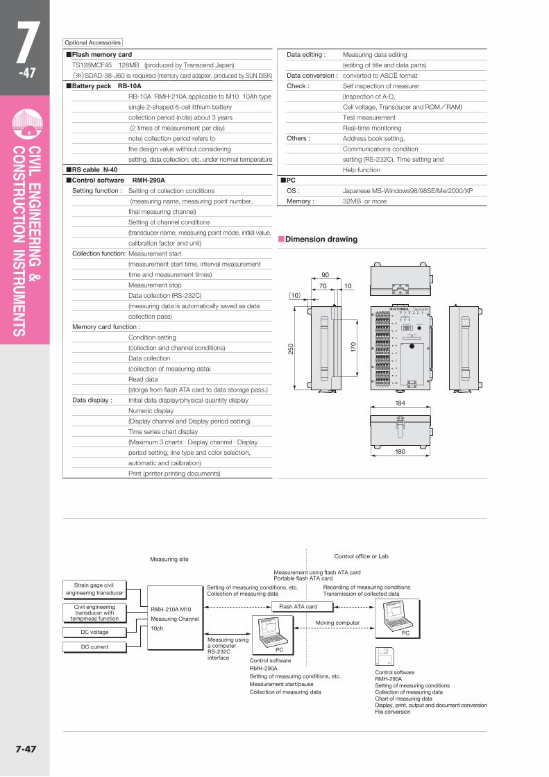
7-47
7-47
CIVIL ENGINEERING & CONSTRUCTION INSTRUMENTS
■Dimension drawing
Optional Accessories
■Flash memory cardTS128MCF45 128MB (produced by Transcend Japan)
(※)SDAD-38-J60 is required (memory card adapter, produced by SUN DISK)
■Battery pack RB-10A RB-10A RMH-210A applicable to M10 10Ah type
single 2-shaped 6-cell lithium battery
collection period (note) about 3 years
(2 times of measurement per day)
note) collection period refers to
the design value without considering
setting, data collection, etc. under normal temperature
■RS cable N-40■Control software RMH-290A
Setting function : Setting of collection conditions
(measuring name, measuring point number,
final measuring channel)
Setting of channel conditions
(transducer name, measuring point mode, initial value,
calibration factor and unit)
Collection function: Measurement start
(measurement start time, interval measurement
time and measurement times)
Measurement stop
Data collection (RS-232C)
(measuring data is automatically saved as data
collection pass)
Memory card function :
Condition setting
(collection and channel conditions)
Data collection
(collection of measuring data)
Read data
(storge from flash ATA card to data storage pass.)
Data display : Initial data display/physical quantity display
Numeric display
(Display channel and Display period setting)
Time series chart display
(Maximum 3 charts · Display channel · Display
period setting, line type and color selection,
automatic and calibration)
Print (printer printing documents)
Data editing : Measuring data editing
(editing of title and data parts)
Data conversion : converted to ASCⅡ format
Check : Self inspection of measurer
(Inspection of A-D,
Cell voltage, Transducer and ROM/RAM)
Test measurement
Real-time monitoring
Others : Address book setting,
Communications condition
setting (RS-232C), Time setting and
Help function
■PCOS : Japanese MS-Windows98/98SE/Me/2000/XP
Memory : 32MB or more
90
70 10(10)
170
250
184
180
Measuring site
PC
PC
Flash ATA card
Setting of measuring conditions, etc.Collection of measuring data
Strain gage civil engineering transducer
Civil engineering transducer with
tempmeas function
DC voltage
DC current
Control office or Lab
RMH-210A M10
Measuring Channel
10ch
Measuring using a computerRS-232Cinterface
Measurement using flash ATA cardPortable flash ATA card
Control softwareRMH-290ASetting of measuring conditions, etc.Measurement start/pauseCollection of measuring data
Control softwareRMH-290ASetting of measuring conditionsCollection of measuring dataChart of measuring dataDisplay, print, output and document conversionFile conversion
Recording of measuring conditionsTransmission of collected data
Moving computer