civil engineering · proceedings of the institution of civil engineers civil engineering ... remote...
TRANSCRIPT
Civil EngineeringVolume 170 Issue CE2 May 2017
■ Stabilising Lyme Regis – a strategic approach ■ Planning and procuring the Shatin–Central cross-harbour rail tunnel, Hong Kong ■ Innovative uses of thermal imaging in civil engineering ■ Sustainable post-earthquake reconstruction in Pakistan
www.civilengineering-ice.comISSN 0965 089 X

Why publish with ICE?
Access to ICE membership – ICE Publishing, as
the publishing arm of ICE, is the only publisher
that brings you direct access to ICE’s worldwide
membership of 80 000.
Visibility – we also have thousands of readers
who are not members of ICE, from corporations,
to governments, to universities. Our journals
are included in major engineering indexes and
resources.
Quality – our journals’ reputation for quality
is unsurpassed, ensuring that the originality,
authority and accuracy of your work will be fully
recognised.
Support – if your paper is accepted, you will have
a dedicated editorial contact who will handle all of
your enquiries and provide you with guidance on
writing your paper.
Marketing – our marketing team has extensive
experience of working with author and librarian
communities to make sure your work is seen by
people who matter, including top academics,
industry leaders, companies and institutions.
Proceedings of the Institution of Civil Engineers
Civil Engineering SPECIAL ISSUEEditors: Philippe Bouillard, Université Libre de Bruxelles, Brussels, Belgium and Priti Parikh, University College London, London, UK
Call for PapersCities of the future
Civil Engineering is planning a special issue for 2018 on cities of the future.
The 21st century has seen a rapid increase in population with over 50% of the
world’s population living in cities. According to report from the Organisation
for Economic Co-operation and Development, the urban population will
increase from less than 1 billion in 1950 to roughly 6 billion by 2050 to
around 9 billion people by end of this century. Rapid urbanisation has brought
in pressures and challenges for the built environment, infrastructure and
resource allocation in cities. There is a need to rethink engineering design and
strategies for future cities.
This can be achieved by going beyond the physical appearance and by
focusing on different representations, properties and impact factors of the
urban system. For that reason, Civil Engineering is calling for a themed issue
on cities of the future to give an overview on the challenges to understand,
shape, plan, design, build, manage and adapt future cities. Priority will be
given to papers containing applications or ongoing collaborative projects
containing a discussion on emerging roles for civil engineers.
Topics to be covered could include the following:
n Sustainable cities, resilient cities, eco districts and green technologies
n High-rise buildings
n Smart cities
n Urban information systems
n Infrastructure and mobility
n Urban water supply and sewage
n Air and noise pollution mitigation
The deadline for submissions is 12 June 2017.
Invitation to authorsTo submit an abstract visit
https://goo.gl/forms/KFcPGweu5PPrRVQU2To submit a full paper visit
www.editorialmanager.com/ceFor further information and full journal
guidelines please contact Ben Ramster T: +44 20 7665 2242;
E: [email protected] more information about the journal, visit
www.icevirtuallibrary.com

49
CONTENTS:May 2017
Contact InformationEditor:Simon Fullalovetel: +44 20 7665 2448email: [email protected] ManagerBen Ramstertel: +44 20 7665 2242email: [email protected] manager, ICE Publishing:Mike Cooksontel: +44 20 7665 2486email: [email protected]:Steve Jackson, Structural Promotions Ltd.12 Lawrance Way, Bourne,Lincolnshire PE10 0HUtel: +44 1778 420 857fax: +44 1778 424 771email: [email protected] byICE PublishingOne Great George Street,WestminsterSW1P 3AAtel: +44 20 7222 7722fax: +44 20 7538 4101email: [email protected]
ICE Publishing is a division of ThomasTelford Ltd, a wholly owned subsidiary of the Institution of Civil Engineers
Production editing by Paul AllansonIllustrations by Barking Dog ArtOrigination by Phoenix Photosetting Ltd, Chatham, KentPrinted in the UK byGD Web Offset Ltd, RotherhamUsing fibre sourced from responsibly managed and sustainable forest
ISSN 0965-089X (Print) 1751-7672 (Online)
© The authors and the Institution of Civil Engineers, 2017Available online at www.civilengineering-ice.com
Subscription InformationNon-members:Subscription enquiries and notification of change of address should be sent to the Customer Services department, ICE Publishing,One Great George Street, Westminster SW1P 3AAtel: +44 20 7665 2460fax: +44 20 7537 2529email: [email protected]
Civil Engineering, 4 issues per year(plus two special issues)2017 subscription price:UK £198; EU £225; Elsewhere £245
ICE Specialist Engineering Journals Collection (formerly full ICE Proceedings Package), 100 issues per year, 2017 subscription price: UK £4680; EU £5345; Elsewhere £5790Members:Subscription enquiries and notification of changes of address should be sent to Membership Registry, Institution of Civil Engineers,PO Box 4479, London SW1P 3XB, UKtel: +44 20 7665 2227fax: +44 20 7222 3514email: [email protected]
The papers and articles express the opinions of the authors, and do not necessarily reflect the views of the ICE, TTL, or the Editorial Panel. Papers are formally refereed by the editorial panel whereas, to ensure topicality, Briefing articles are not refereed.Civil Engineering is indexed in the Science Citation Index
CIVIL ENGINEERING EDITORIAL PANELChairman Emma Kent, CEng, MICE,MIStructE, Cundall, London, UKAndy Alder, CH2M, London, UKDavid Atherton, BSc, MSc, CEng, CGeol, FICE, FIMMM, FCIWEM, MCIWM, FGS,
Peter Brett Associates, Reading, UKPhilippe Bouillard, BSc, MSc, PhD, Hab, MICE, FAUA, Université Libre
de Bruxelles, BelgiumYancheng Cai, PhD, MIASS, Meinhardt (C&S) Ltd, Hong Kong,
PR ChinaJohn Clifton, BSc, CEng, CEnv, FICE, FCIHT, MCMI, Independent Consultant,
Santa Barbara de Nexe, PortugalVeronica Flint Williams, BEng, CEng, FICE, MAPM, Environment Agency,
Leeds, UKNick Gorst, BEng, PhD, CEng, MICE, PIEMA, British Precast, Leicester, UKDavid Hobson, HS2 Ltd, Birmingham UKSebastian Lewandowski, Highways England, Birmingham, UKEva Linnell, MEng, CEng, MICE, Atkins, Bristol, UK
Andrew Martin, BEng, MSt, CEng, MICE, MIStructE, COWI A/S, Kongens Lyngby, Denmark
David Oloke, Progressive Concept Consultancy Ltd, Walsall, UKNeil Owen, BSc, CEng, MICE, Independent Consultant,
Birmingham, UKPriti Parikh, PhD, CEng, MICE, FRSA, University College London, UKJohn Porter, CEng, FICE, FHKIE, MASCE, MAPM, Continental
Engineering Corporation, TaiwanJamie T. Radford, MA, MEng, Mott MacDonald, Cambridge, UKColin Rawlings, BSc, DIC, MSc, CEng, MICE, MASCE, CGeol, FGS, CH2M/HS2
Ltd, London, UKStuart Ross, Arup, Hong Kong, PR ChinaP. J. Rudden, RPS Group, Killiney, Republic of IrelandAndy Simpson, MEng(Hons), CEng, MICE, Andrew Waring
Associates, Romsey, UKAlessandra Villa, CEng, MICE, Dott. Ing., Arup, London, UK
Proceedings of the Institution of Civil Engineers
Civil EngineeringVolume 170 Issue CE2 May 2017
PAGE 69 PAGE 72 PAGE 85 PAGE 95
Civil EngineeringEDITORIAL
BRIEFING
Edinburgh’s hyperloop team predicts a transport revolution 51Structural health monitoring of infrastructure with sensors: from detection to prevention 52Mixed reality constructs a new frontier for maintaining the built environment 53HS2 project creates and updates British standards and guidance to improve delivery 54New tool will help civil engineers meet CDM requirements to design for safety 55UK skills crisis: learning lessons from Crossrail for staffing future infrastructure projects 56
MONITOR
Books 57ICE Proceedings 60ICE review 62
TECHNICAL PAPERS
Stabilising Lyme Regis – a strategic approachR. Moore, G. Davis, M. Stannard and N. Browning 63
Planning and procuring the Shatin–Central cross-harbour rail tunnel, Hong KongR. Au, F. Aikawa, M. Morris and CK Tsang 71
Innovative uses of thermal imaging in civil engineeringI. Thusyanthan, T. Blower and W. Cleverly 81
Sustainable post-earthquake reconstruction in PakistanM. M. Rafi, N. Ahmed and S. H. Lodi 89
50
EditorialColin Rawlings BSc, DIC, MSc, CEng, MICE, MASCE, FGS, CGeolCH2M/High Speed Two, London, UK
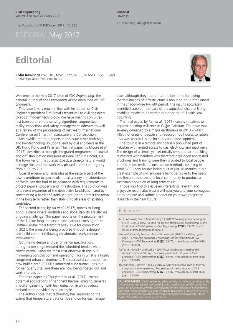
Welcome to the May 2017 issue of Civil Engineering, the general journal of the Proceedings of the Institution of Civil Engineers.
This issue is very much in line with Institution of Civil Engineers president Tim Broyd’s recent call to civil engineers to adopt modern technology. We have briefings on ultra-fast transport, remote sensing algorithms, augmented-reality inspections and safety management software as well as a review of the proceedings of last year’s International Conference on Smart Infrastructure and Construction.
Meanwhile, the four papers in this issue cover both high- and low-technology solutions used by civil engineers in the UK, Hong Kong and Pakistan. The first paper, by Moore et al. (2017), describes a strategic integrated programme of coastal and cliff stabilisation measures at Lyme Regis in Dorset, UK. The town lies on the Jurassic Coast, a Unesco natural world heritage site, and the work was phased in order of urgency from 1993 to 2015.
Coastal erosion and landslides at the eastern part of the town contribute to spectacular local scenery and abundance of fossils, yet this had to be balanced with requirements to protect people, property and infrastructure. The solution was to prevent expansion of the destructive landslides inland by constructing a barrier of stabilised ground to protect the town in the long term rather than stabilising all areas of existing landslides.
The second paper, by Au et al. (2017), moves to Hong Kong, a place where landslides and slope stability are also an ongoing challenge. This paper reports on the procurement of the 1·4 km long immersed-tube harbour crossing of the Shatin–Central mass transit railway. Due for completion in 2021, the project is being procured through a design-and-build contract following collaborative early contractor involvement.
Optimising design and performance specifications during tender stage ensured the submitted tenders were constructable, using the most cost-effective design but minimising construction and operating risks in what is a highly congested urban environment. The successful contractor has now built eleven 23 000 t immersed-tube tunnel units in a former quarry site, and these are now being floated out and sunk into position.
The third paper, by Thusyanthan et al. (2017), covers potential applications of handheld thermal imaging cameras in civil engineering, with leak detection in an aqueduct embankment provided as an example.
The authors note that technology has improved to the extent that temperature data can be shown for each image
pixel, although they found that the best time for taking thermal images of infrastructure is about an hour after sunset in the shadow-free twilight period. The results accurately identified cracks in the base of the aqueduct channel lining, enabling repairs to be carried out prior to a full-scale leak occurring.
The final paper, by Rafi et al. (2017), covers initiatives to improve building resilience in Gajjar, Pakistan. The town was severely damaged by a major earthquake in 2013 – which killed hundreds of people and reduced mud houses to rubble – so was selected as a pilot study for redevelopment.
The town is in a remote and sparsely populated part of Pakistan with limited access to gas, electricity and machinery. The design of a simple yet seismically resistant earth building reinforced with bamboo was therefore developed and tested. Brochures and training were then provided to local people in these more resilient construction methods, resulting in some 6000 new houses being built in just 18 months. It is a great example of civil engineers being sensitive to the needs and limited resources of a local community to produce a sustainable solution of long-term value.
I hope you find this issue an interesting, relevant and enjoyable read. I also trust it will spur you and your colleagues on to prepare and submit a paper on your own project or research in the near future.
Civil EngineeringVolume 170 Issue CE2 May 2017
http://dx.doi.org/10.1680/jcien.2017.170.2.50
EditorialRawlings
ICE Publishing: All rights reserved
EDITORIAL:May 2017
References
Au R, Aikawa F, Morris M and Tsang CK (2017) Planning and procuring the Shatin–Central cross-harbour rail tunnel, Hong Kong. Proceedings of the Institution of Civil Engineers – Civil Engineering 170(2): 71–79, http://dx.doi.org/10.1680/jcien.15.00072.
Moore R, Davis G, Stannard M and Browning N (2017) Stabilising Lyme Regis – a strategic approach. Proceedings of the Institution of Civil Engineers – Civil Engineering 170(2): 63–70, http://dx.doi.org/10.1680/jcien.16.00008.
Rafi MM, Ahmed N and Lodi SH (2017) Sustainable post-earthquake reconstruction in Pakistan. Proceedings of the Institution of Civil Engineers – Civil Engineering 170(2): 89–95, http://dx.doi.org/10.1680/jcien.16.00015.
Thusyanthan I, Blower T and Cleverly W (2017) Innovative uses of thermal imaging in civil engineering. Proceedings of the Institution of Civil Engineers – Civil Engineering 170(2): 81–87, http://dx.doi.org/10.1680/jcien.16.00014.
CALL FOR PAPERS: Civil Engineering relies entirely on material contributed by civil engineers and related professionals. Illustrated articles of 600 words and papers of 2000 to 3500 words are welcome on any relevant civil engineering topic that meets the journal’s aims of providing a source of reference material, promoting best practice and broadening civil engineers’ knowledge, Please contact the editor for further information
51
For further information please contact: Adam Anyszewski Tel: +44 7999 907198 Email: [email protected] Web: hyp-ed.com or facebook.com/hypedinburgh
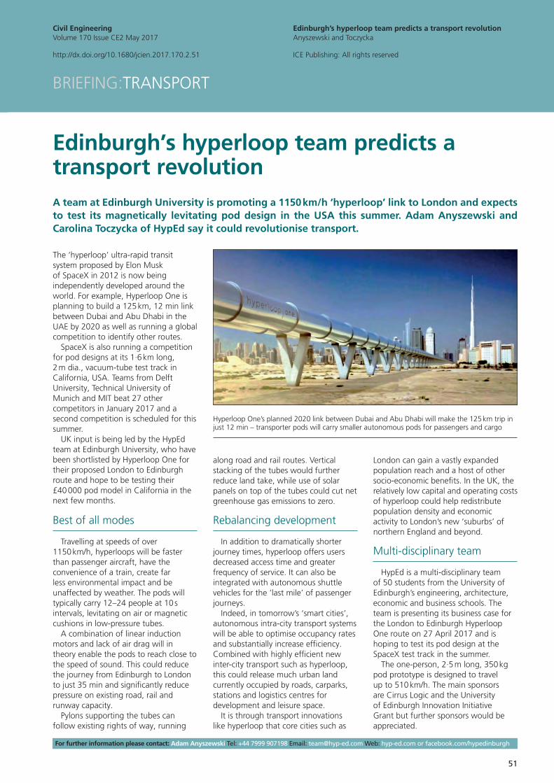
The ‘hyperloop’ ultra-rapid transit system proposed by Elon Musk of SpaceX in 2012 is now being independently developed around the world. For example, Hyperloop One is planning to build a 125 km, 12 min link between Dubai and Abu Dhabi in the UAE by 2020 as well as running a global competition to identify other routes.
SpaceX is also running a competition for pod designs at its 1·6 km long, 2 m dia., vacuum-tube test track in California, USA. Teams from Delft University, Technical University of Munich and MIT beat 27 other competitors in January 2017 and a second competition is scheduled for this summer.
UK input is being led by the HypEd team at Edinburgh University, who have been shortlisted by Hyperloop One for their proposed London to Edinburgh route and hope to be testing their £40 000 pod model in California in the next few months.
Best of all modes
Travelling at speeds of over 1150 km/h, hyperloops will be faster than passenger aircraft, have the convenience of a train, create far less environmental impact and be unaffected by weather. The pods will typically carry 12–24 people at 10 s intervals, levitating on air or magnetic cushions in low-pressure tubes.
A combination of linear induction motors and lack of air drag will in theory enable the pods to reach close to the speed of sound. This could reduce the journey from Edinburgh to London to just 35 min and significantly reduce pressure on existing road, rail and runway capacity.
Pylons supporting the tubes can follow existing rights of way, running
along road and rail routes. Vertical stacking of the tubes would further reduce land take, while use of solar panels on top of the tubes could cut net greenhouse gas emissions to zero.
Rebalancing development
In addition to dramatically shorter journey times, hyperloop offers users decreased access time and greater frequency of service. It can also be integrated with autonomous shuttle vehicles for the ‘last mile’ of passenger journeys.
Indeed, in tomorrow’s ‘smart cities’, autonomous intra-city transport systems will be able to optimise occupancy rates and substantially increase efficiency. Combined with highly efficient new inter-city transport such as hyperloop, this could release much urban land currently occupied by roads, carparks, stations and logistics centres for development and leisure space.
It is through transport innovations like hyperloop that core cities such as
London can gain a vastly expanded population reach and a host of other socio-economic benefits. In the UK, the relatively low capital and operating costs of hyperloop could help redistribute population density and economic activity to London’s new ‘suburbs’ of northern England and beyond.
Multi-disciplinary team
HypEd is a multi-disciplinary team of 50 students from the University of Edinburgh’s engineering, architecture, economic and business schools. The team is presenting its business case for the London to Edinburgh Hyperloop One route on 27 April 2017 and is hoping to test its pod design at the SpaceX test track in the summer.
The one-person, 2·5 m long, 350 kg pod prototype is designed to travel up to 510 km/h. The main sponsors are Cirrus Logic and the University of Edinburgh Innovation Initiative Grant but further sponsors would be appreciated.
Edinburgh’s hyperloop team predicts a transport revolutionA team at Edinburgh University is promoting a 1150 km/h ‘hyperloop’ link to London and expects to test its magnetically levitating pod design in the USA this summer. Adam Anyszewski and Carolina Toczycka of HypEd say it could revolutionise transport.
BRIEFING:TRANSPORT
Edinburgh’s hyperloop team predicts a transport revolutionAnyszewski and Toczycka
ICE Publishing: All rights reserved
Civil EngineeringVolume 170 Issue CE2 May 2017
http://dx.doi.org/10.1680/jcien.2017.170.2.51
Hyperloop One’s planned 2020 link between Dubai and Abu Dhabi will make the 125 km trip in just 12 min – transporter pods will carry smaller autonomous pods for passengers and cargo
52
For further information contact: Marcus Perry Tel: +44 141 548 4942 Email: [email protected]
In the UK alone there are over 10 000 bridges used by millions of people every day. The integrity of these and other infrastructures underpins the well-being of the national economy, so effective structural health monitoring is vital to ensure their continued safety and operation.
Structural health monitoring is still usually conducted by civil and structural engineers performing manual inspections to assess on-site structural integrity. The approach is not entirely effective, as it is subjective and only permits a reactive response to damage that has already occurred – generally as visible damage.
However, large-scale sensor networks for structural health monitoring are becoming increasingly common, with many of today’s megastructures being instrumented with hundreds of sensors. While this solves the inspection issue, it creates another problem as the deluge of data must be converted into useful information.
Limited value of sensors
The data analytics used by modern sensor networks can limit their value: most are reactive and simply test sensor records against fixed thresholds. Many infrastructure operators therefore feel that a convincing financial argument for investing in monitoring technology is yet to be made.
Currently, there are no structural health monitoring methods for pinpointing early-warning signals of structural damage well before they occur. Although existing systems have an array of threshold-activated damage-detection methods, they cannot spot damage far in advance of it occurring.
To do so would require damage-sensitive features of structures to be identified and then statistically analysed to identify subtle structural changes using sensor network data. It would also need rapid and automated predictive data-analysis methods to enable engineers to monitor the onset of damage in real time and then act before it occurs.
Tipping point analysis
A study to improve the value of sensor data is being conducted by a team of researchers from the UK’s National Physical Laboratory and the University of Strathclyde. The aim is to move existing structural health monitoring systems towards a more preventive model.
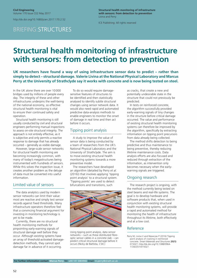
The researchers have developed an algorithm (detailed by Perry et al. (2016)) that involves applying ‘tipping point analysis’ to a structural system. ‘Tipping points’ are used to detect bifurcations and transitions, such
as cracks, that create a new and potentially undesirable state in the structure that could not previously be predicted.
In tests on reinforced concrete, the algorithm successfully provided early-warning signals of tiny changes in the structure before critical damage occurred. The value and performance of existing structural health monitoring systems can therefore be improved by the algorithm, specifically by extracting information on tipping point precursors from data already being collected.
The method shifts detection to being predictive and thus maintenance to being preventive, thereby reducing lifetime maintenance costs. Data analysis efforts are also focused and reduced through extraction of the information, as intervention only becomes necessary when the early-warning signals are triggered.
Ongoing research
The research project is ongoing, with the method currently being tested on steel beams and real-life systems. The goal is to develop hardware and software products that, when used in conjunction with existing structural health monitoring systems, will provide a rapid and automated method for monitoring the health of infrastructure throughout its lifetime, both effectively and at a low cost.
Reference
Perry M, Livina V and Niewczas P (2016) Tipping point analysis of cracking in reinforced concrete. Smart Materials and Structures 25(1): 015027, http://dx.doi.org/10.1088/0964-1726/25/1/015027.
Structural health monitoring of infrastructure with sensors: from detection to preventionUK researchers have found a way of using infrastructure sensor data to predict – rather than simply to detect – structural damage. Valerie Livina at the National Physical Laboratory and Marcus Perry at the University of Strathclyde say it works with concrete and is now being tested on steel.
BRIEFING:STRUCTURES
Structural health monitoring of infrastructure with sensors: from detection to preventionLivina and Perry
ICE Publishing: All rights reserved
Civil EngineeringVolume 170 Issue CE2 May 2017
http://dx.doi.org/10.1680/jcien.2017.170.2.52
Using tipping point analysis, data sensor networks – such as these distributed fibre-optic sensor cables in a concrete slab – can predict critical structural damage before it occurs (Nicky de Battista, CSIC)

53
For further information please contact: Ioannis Brilakis, Tel: +44 1223 332718, Email: [email protected] Web: http://cit.eng.cam.ac.uk
Cambridge University is partnering with Trimble and Microsoft to combine physical infrastructure data – such as design, construction and operational data – that are currently stored in separate archives. The goal is to make them available to civil engineers and other construction professionals through the latest ‘mixed reality’ technologies.
While civil engineers have built millions of physical assets over many centuries, they have done relatively little to create digital data repositories with integrated geometry, design, construction and operation data. This is not surprising given most existing physical assets started their life cycle well before modern digital engineering technologies existed.
Digital asset data
As such, digital data for infrastructure assets are only partially available, rarely up-to-date and almost never integrated
into a single platform so that informed decisions can be made. Building information modelling technology is changing that by delivering a ‘digital copy’ of an asset, bringing all types of data together for use over the asset’s lifetime.
The objective is to provide civil engineers, facilities managers and other asset stakeholders with the information they need to make informed decisions and better manage the assets throughout their life cycle. Enabling them to engage with the digital asset models through mixed reality will also greatly improve productivity and sustainability.
Construction monitoring
For example, monitoring construction site progress is a laborious, time-consuming and error-prone task. Research at Cambridge has led to a Microsoft Hololens application which will help to automate progress inspections.
The application, which will be transferred to practice through Trimble, allows inspectors wearing Hololens headsets to see a three-dimensional as-planned digital model of the works overlaid on the as-built works as they walk around it. Once aligned, the model remains fixed relative to the scene, remains stable and has no occlusions.
The application then automatically compares the as-built status with the as-planned data to provide instant progress information as the inspector moves around the site. This information allows inspectors to detect any schedule
or specification discrepancies at the earliest opportunity, enabling early corrective action to be taken.
Bridge inspection
Another example is the visual inspection of bridges, which usually has to take place annually or biennially. These inspections are laborious, require traffic control and pose a health and safety risk for the inspector.
Cambridge University is working on methods to build fully textured, data-rich and geometrically accurate models of existing bridges which can then be used for remote off-site inspections. Data are collected during on-site maintenance operations or with drones and automatically converted to an as-is model.
Element surface texture is extracted from high-resolution images and defects are automatically identified. Using Hololens, inspectors can look at the real-sized bridge model in the comfort of their offices and be guided automatically to areas of concern.
Context-based workflow
The two examples clarify the value of presenting data in context. By merging the digital and physical worlds, mixed reality enables a context-based workflow. It transforms the way civil engineers consume, interact with and communicate information.
Through Hololens and other technologies, Trimble, Microsoft and the University of Cambridge are working together to develop a new generation of solutions towards improved automation in construction.
Mixed reality constructs a new frontier for maintaining the built environmentNew technology that intelligently combines the physical and digital worlds looks set to revolutionise the way civil engineers monitor infrastructure, both during and after construction. Ioannis Brilakis of the University of Cambridge reports.
BRIEFING:INFORMATION TECHNOLOGY
Mixed reality constructs a new frontier for maintaining the built environmentBrilakis
ICE Publishing: All rights reserved
Civil EngineeringVolume 170 Issue CE2 May 2017
http://dx.doi.org/10.1680/jcien.2017.170.2.53
Mixed reality techniques will enable remote inspection of bridges using 3D models complete with highlighted defects
54
For further information contact: Colin Rawlings Tel: +44 20 7944 0759 Email: [email protected] Web: www.hs2.org.uk
In 2014, High Speed Two Ltd (HS2) was specifically tasked with generating savings for the £55·7 billion government-funded rail project through creating and updating UK civil engineering standards and guidance documents (Wilson et al., 2015).
In fulfilling the task, HS2’s efficiency challenge programme team worked closely with BSI, Ciria, the British Tunnelling Society, Temporary Works Forum and Institute of Concrete Technology.
Workshops were held at BSI and Ciria offices with industry representatives in 2014 to identify potential documents and topics, after which steering group members – including contractors, consultants, clients and other organisations – produced the initial drafts.
The documents were then sent out for consultation, both within the UK and internationally, ensuring they all have wide industry support.
New publicly available specifications
Four new publicly available specifications (PAS) have been produced. PAS 8820 (BSI, 2016a) (also sponsored by David Ball Group and Hanson UK) covers the performance of alkali-activated cementitious materials in low-carbon dioxide cements and concretes.
PAS 8812 (BSI, 2016b) gives guidance on the application of European standards to the design of temporary works, promoting consistency and removing uncertainties for temporary works designers, while PAS 8811 (BSI, 2017) covers major infrastructure client procedures to provide a unified approach to client involvement in temporary works across all stages.
PAS 8810 (BSI, 2016c) fills a gap in the industry to cover the design of precast
concrete segmental tunnel linings, introducing some standardisation and consensus of design requirements.
Updating standards to Eurocodes
Three existing British standards were updated to comply with Eurocodes, including providing non-contradictory, complementary information for use with other Eurocodes and their UK national annexes.
BS 8002 (BSI, 2015a) now provides guidance on the selection of Eurocode design parameters for soils and model factors to be applied to prop loads and has been updated to cover advances in retaining structure technology.
BS 8004 (BSI, 2015b) now provides Eurocode design parameters for soils, guidance on spread and pile foundation design and has been updated to cover advances in foundation technology. Definitions were included for various reports.
Finally, BS 8081 (BSI, 2015c) now provides recommendations for the design, construction, stressing, testing, monitoring and maintenance of grouted anchors as defined in Eurocodes.
Updated guidance document
Ciria’s Guidance on Embedded Retaining Wall Design (Ciria, 2017) has been updated to satisfy Eurocode requirements and presents a clear, unambiguous method for the application of the observational method. Ground types have been extended, case studies added and the need for a representative ground model stressed.
HS2’s aim is that the new and updated standards and guidance documents will also benefit other major clients and major infrastructure projects, such as Highways England, London Underground, Transport for London, Network Rail, National Grid, Thames Tideway, Crossrail 2 and internationally.
In addition to their impact upon efficiency, the standards and documents provide sustainability and innovation in line with the government’s construction strategy.
ReferencesBSI (2015a) BS 8002:2015: Code of practice for
earth retaining structures. BSI, London, UK.BSI (2015b) BS 8004:2015: Code of practice for
foundations. BSI, London, UK.BSI (2015c) BS 8081:2015: Code of practice for
grouted anchors. BSI, London, UK.BSI (2016a) PAS 8820: Construction materials
– Alkali-activated cementitious material and concrete – Specification. BSI, London, UK.
BSI (2016b) PAS 8812: Temporary works – Application of European standards in design – Guide. BSI, London, UK.
BSI (2016c) PAS 8810: Tunnel design – Design of concrete tunnel linings – Code of practice. BSI, London, UK.
BSI (2017) PAS 8811: Temporary works – Major infrastructure client procedures – Code of practice. BSI, London, UK.
Ciria (2017) Guidance on Embedded Retaining Wall Design. CIRIA, London, UK, C760.
Wilson S, Grose B and Rawlings C (2015) Improving infrastructure delivery through better use of standards. Proceedings of the Institution of Civil Engineers – Civil Engineering 168(1): 9, http://dx.doi.org/10.1680/cien.2015.168.1.9.
HS2 project creates and updates British standards and guidance to improve deliveryInefficient and inconsistent use of codes, standards and guidance documents can hamper effective delivery of infrastructure projects. Colin Rawlings of CH2M/High Speed Two Ltd (HS2) summarises initiatives taken on the project to deliver new and updated standards and guidance.
BRIEFING:STANDARDS
HS2 project creates and updates British standards and guidance to improve deliveryRawlings
ICE Publishing: All rights reserved
Civil EngineeringVolume 170 Issue CE2 May 2017
http://dx.doi.org/10.1680/jcien.2017.170.2.54
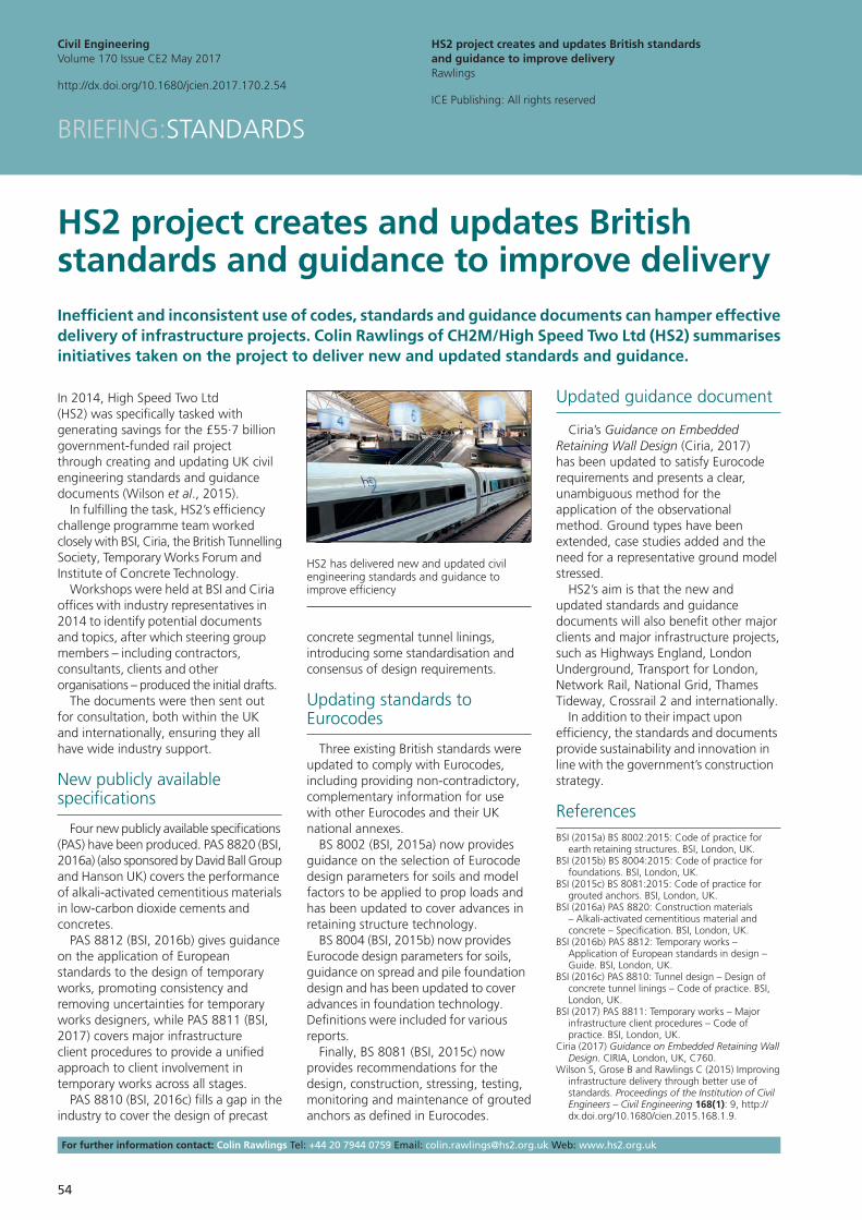
HS2 has delivered new and updated civil engineering standards and guidance to improve efficiency
55
For further information please contact: Patrick Manu Tel: +44 11 7328 7306 Email: [email protected]
In the UK over the past decade, the construction sector has consistently accounted for a greater proportion of the number of occupational fatalities, injuries and illnesses (HSE, 2015a).
While there have been many occupational safety and health improvements in the industry over recent years, the persistent and often tragic accidents are a constant reminder that sustained effort is still needed to keep driving down the number of injuries and illnesses in the sector.
Among the array of mechanisms for improving occupational health and safety, regulatory influence can be a powerful stimulus for improvement. In the UK, one of the prominent occupational health and safety regulations for the construction sector is the Construction (Design and Management) Regulations 2015 (HMG, 2015) – the ‘CDM Regulations’ (HSE, 2015b).
Design for safety
Studies in the UK and other countries have confirmed the link between design and the occurrence of accidents and injuries in construction (Behm, 2005; Gibb et al., 2006; Manu et al., 2014). As a result there is a growing importance for designers to consider the occupational health and safety implications of their design. This is generally referred to as ‘design for safety’ or ‘safety in design’.
In the UK, design for safety has been prominent since the introduction of the CDM Regulations in the mid-1990s. While there are a number of changes in the 2015 regulations, fundamentally designers are still required to seek to mitigate occupational health and safety risk through their designs. CDM 2015
requires that the designer preparing or modifying designs should seek to eliminate, reduce or control foreseeable risks that may arise during the construction, maintenance and use of built assets.
Organisational capability
Additionally, organisations with design responsibilities are expected to have the appropriate organisational capability to carry out their design role in a way that secures occupational health and safety. This could be termed ‘organisational design for safety capability’, and those appointing design organisations also ought to ensure that this capability is appropriate for the project.
However, there is a lack of clarity regarding what constitutes organisational design for safety capability. There is therefore an urgent need for research in the built environment sector to address this gap. This is not only important from the standpoint of fulfilling CDM 2015 requirements, but more so from an organisational continuous process improvement perspective.
New research project
The Engineering and Physical Sciences Research Council has provided funding (grant no. EP/N033213/1) for research work aimed at developing a design for safety capability maturity indicator tool for the construction sector.
The research is being undertaken by a coalition of the Universities the West of England and Loughborough in the UK and East Carolina University in the USA. Industry partners contributing towards the research include Bam Construction Limited, the Health and Safety Executive, Heathrow Airport, ISG, Mott MacDonald, Nick Bell Risk Consultancy, GCP Architects and Safety in Design.
The research project started in October 2016 and will be completed in September 2018. It is anticipated that the tool will be ready for use by designers in May 2018.
References
Behm M (2005) Linking construction fatalities to the design for construction safety concept. Safety Science 43(8): 589–611.
Gibb A, Haslam R, Gyi D, Hide S and Duff R (2006) What causes accidents? Proceedings of the Institution of Civil Engineers – Civil Engineering 159(6): 46–50, http://dx.doi.org/10.1680/cien.2006.159.6.46.
HMG (Her Majesty’s Government) (2015) Health and Safety. The Construction (Design and Management) Regulations 2015. The Stationery Office, London, UK, Statutory Instrument 2015 No. 51.
HSE (Health and Safety Executive) (2015a) Historical Picture – HISTINJ – Reported Injuries in Great Britain by Main Industry and Severity of Injury, 1974 to Latest Year. HSE, Bootle, UK. See http://www.hse.gov.uk/Statistics/tables/index.htm (accessed 12/07/2016).
HSE (2015b) Managing Health and Safety in Construction – CDM 2015 Guidance L153. HSE, Bootle, UK.
Manu P, Ankrah N, Proverbs D and Suresh S (2014) The health and safety impact of construction project features. Engineering Construction and Architectural Management 21(1): 65–93.
New tool will help civil engineers meet CDM requirements to design for safetyA new tool is being developed to help civil engineers and other construction professionals improve their capability to design for safety under the Construction (Design and Management) Regulations. Patrick Manu and Lamine Mahdjoubi of the University of the West of England, Alistair Gibb of Loughborough University and Michael Behm of East Carolina University report.
BRIEFING:SAFETY
New tool will help civil engineers meet CDM requirements to design for safetyManu, Mahdjoubi, Gibb and Behm
ICE Publishing: All rights reserved
Civil EngineeringVolume 170 Issue CE2 May 2017
http://dx.doi.org/10.1680/jcien.2017.170.2.55
The design for safety tool currently being researched and developed should be available in May 2018
56
For further information contact: Graham Day Tel: +44 20 3047 2339 Email: [email protected] Web: matchtech.com/voice-of-the-workforce
Confidence is booming across the UK civil engineering sector. The promise of additional funding for transport in chancellor Philip Hammond’s autumn statement last November has only added to the positive feeling within the profession.
Matchtech’s January 2017 Voice of the Workforce survey of 2500 engineers echoes this, with 72% of civil engineers working in rail believing the sector will grow over the next 12 months. With a number of megaprojects in the pipeline, not least the £56 billion High Speed Two (HS2) railway, there is a risk that the UK talent pool will be stretched over the coming years.
Add a post-Brexit uncertainty around the free movement of people and the civil engineering sector as a whole is faced with a real challenge. However, the profession can build on the success of Crossrail to ensure that Britain is prepared to deliver these transformational infrastructure projects.
A flexible approach
The £15 billion Crossrail project to deliver the east–west Elizabeth line across London demanded a very specific combination of skill sets. For example, project managers required all computer-aided design contractors to use the same software and sit in the same central office, which limited access to talent across the UK and abroad.
Future projects, particularly those on the scale of HS2, will require a more flexible and sustainable approach to recruitment in order to attract the high number of people the project will require. Beyond the ability to work
remotely, the transfer of relevant skills should be encouraged.
High-value projects such as Heathrow Airport expansion and Hinkley Point C nuclear power station have uncovered an array of expertise across other sectors and HS2 is already running specific courses across the UK to utilise these more diverse talent pools.
Attracting new talent
Another lesson learned from Crossrail was the need to attract a new generation of skilled professionals. Many of the contracting staff were also involved with High Speed One in the 1990s – while this experience is invaluable, the scale and volume of planned rail schemes requires a fresh intake of engineering talent.
Since its inception, Crossrail has faced competition from several major global projects. Lucrative expatriate markets have drawn both UK-based and overseas talent away, leaving resource gaps and recruitment headaches. Moving forward, the UK must celebrate its rich heritage in the civil engineering sector and underline the global significance of upcoming projects.
HS2, for example, should be positioned as a career-defining scheme to retain our best engineers. Over two-thirds of rail engineers are confident about career progression within the next 12 months – this is a sentiment that should be built upon.
International outlook
Attracting the world’s top talent has been integral to the delivery of infrastructure projects in the UK. The nation’s decision to leave the European Union last June has left an air of uncertainty over the movement of skilled labour. However, the government’s lofty infrastructure ambitions will require access to this resource.
During Crossrail, recruiters and project managers have successfully learned to cast the net wider, even beyond the EU, and demand for specialist skills will be driven even higher by HS2 and other planned infrastructure developments.
Therefore, the fundamental focus for the civil engineering industry is using success stories like Crossrail to position the UK as a global hub for infrastructure engineering, both for home-grown and overseas talent.
UK skills crisis: learning lessons from Crossrail for staffing future infrastructure projectsThe UK infrastructure industry could soon be facing a major skills crisis, with several megaprojects about to start and concerns about the effects of Brexit on the flow of talent. Graham Day at recruiter Matchtech says experience gained on Crossrail should help the industry to attract sufficient people.
BRIEFING:RECRUITMENT
UK skills crisis: learning lessons from Crossrail for staffing future infrastructure projectsDay
ICE Publishing: All rights reserved
Civil EngineeringVolume 170 Issue CE2 May 2017
http://dx.doi.org/10.1680/jcien.2017.170.2.56
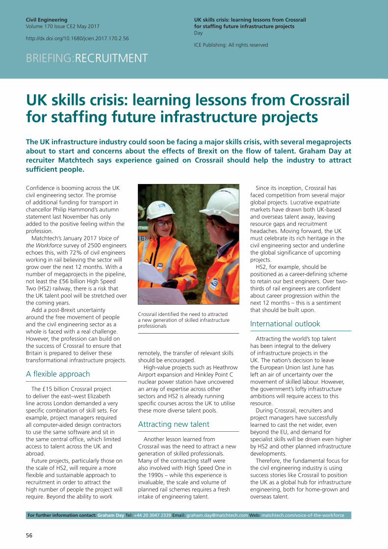
Crossrail identified the need to attracted a new generation of skilled infrastructure professionals
57
Civil EngineeringVolume 170 Issue CE2 May 2017
http://dx.doi.org/10.1680/jcien.2017.170.2.57
Monitor: Books
ICE Publishing: All rights reserved
BooksREVIEWS
Transforming the future of infrastructure through smarter informationby Robert Mair, Kenichi Soga, Ying Jin, Ajith Parlikad and Jennifer Schooling, published by ICE Publishing, 2016, £150, reviewed by Colin Rawlings, HS2 Ltd, UK
According to Institution of Civil Engineers president Tim Broyd, civil engineers ‘will not be able to meet society’s changing expectations without using modern technology’. This 782-page proceedings of last year’s International Conference on Smart Infrastructure and Construction 2016 is a good place to start.
The 127 papers are in three sections. The first explains how recent innovations in sensor systems and development of new data-analysis methods can improve understanding of performance – including infrastructure health monitoring – through a project life cycle.
The second shows how smart sensing can provide data to make effective asset management decisions to ensure long-term value and sustainability of infrastructure, while the third covers new technology and business models to improve resilience and adaptability in the urban environment.
This is truly a remarkable conference proceedings, providing relevant information for contractors, designers, clients, infrastructure operators, asset managers and others within the built environment. It will help them to make efficiencies throughout the life cycles of new and existing projects using smart data and sensing.
Whole-life value-based decision-making in asset managementby Ajith Parlikad and Rengarajan Srinivasan, published by ICE Publishing, 2016, £45, reviewed by Stuart Ross, Arup, UK
Increasingly, civil engineers need to make infrastructure asset decisions based on whole-life value assessments, not just cost. This book provides a concise and structured summary of how to support value-based asset management decisions.
Readers familiar with ISO 55000 asset management standards will find the book particularly useful. Although aimed at infrastructure owners, it is also relevant to those who have responsibilities for operation and maintenance of assets, including designers.
After describing the concept of value-based asset management, the book takes the reader through each stage of the process, starting with establishing the context and developing the value map to the final stages of assessment and optimisation of value. It then shows how the processes can be applied to a railway tunnel project and a scheme to replace roadside safety barriers.
The writing style is simple, with many flow charts and diagrams helping to illustrate the processes described. With whole-life value becoming an increasingly important issue for the construction industry, this book will be an invaluable resource for those involved in the operation and maintenance of infrastructure assets.
NEC3: the role of the project managerby Bronwyn Mitchell and Barry Trebes, ICE Publishing, 2016, £40, reviewed by Andrew Martin, Cowi, Denmark
The performance of the role of project manager is key to the successful functioning of the NEC3 Engineering and Construction Contract (ECC), which seeks to promote and stimulate good practice in the management of projects.
This book provides guidance to NEC project managers on the obligations, activities and culture which are necessary to carry out the role effectively, requiring a blend of hard and soft skills. The book explains the role of the NEC project
manager through the chronology of an ECC contract, making use of helpful lists and flow charts within the text. A series of checklists and draft agendas for contractual meetings are included as appendices.
The book provides valuable guidance to those new in the role of NEC project manager or who are seeking to improve their knowledge of the ECC. It will also be a useful reference work for more experienced NEC project managers.
Construction planning (2nd ed.)by Richard Neale, David Neale and Paul Stephenson, published by ICE Publishing, 2016, £30, reviewed by Stuart Ross, Arup, UK
The importance of planning construction projects is often discounted. This book aims to give students and those at the early stages of their career a concise explanation of the processes and techniques required for effective planning and control of construction works.
The book starts by describing the importance of planning and early decisions. It then reviews the various techniques, procedures and methods which can be used in construction planning, including an overview of programme types, how resources can be considered and, critically, monitoring and controlling throughout the project.
The authors conclude with a description of how the planning techniques can be put into practice with case studies provided for context. There are many diagrams and flow charts that allow the reader to understand quickly and easily the techniques and principles described.
This book will be an extremely useful resource for those at the early stages of their construction career and would also be a useful reference for those looking to refresh their construction planning knowledge.
MONITOR:BOOKS
58
Civil EngineeringVolume 170 Issue CE2 May 2017
Monitor: Books
MONITOR:BOOKS
Crossrail project: infrastructure design and construction (Volume 3)edited by Mike Black, published by ICE Publishing, 2016, £65, reviewed by David Oloke, Progressive Concept Consultancy, UK
This book – the third in one of Crossrail’s ‘learning legacy’ series – contains 34 design and construction papers submitted by consultants, contractors, suppliers and third-party stakeholders on Europe’s biggest rail project.
Over half of the contributions relate to innovations while others cover outputs from desktop studies, feasibility, design and post-construction monitoring and forensics. The client involvement in all contributions makes it an authoritative compendium.
In addition, the simplicity with which information is presented makes the book a worthy companion for civil engineers and other construction professionals. Academics will also find it useful for final-year undergraduate and postgraduate case studies.
Conceptual structural design: bridging the gap between architects and engineers (2nd ed.)by Olga Larsen, published by ICE Publishing, 2016, £40, reviewed by Andy Simpson, Andrew Waring Associates, UK
This book is refreshingly non-technical, with author Olga Larsen conveying structural concepts and fundamentals in a clear manner without a single equation.
The first chapter excellently defines the sometimes-difficult relationship between structural engineers and architects. It goes on to describe the link between nature and how structural elements work. Larsen showcases associations between today’s modern buildings and the primitive structures of the past, and the importance of designing from precedent.
Chapter six features examples of innovative structural form-finding –
the discovery of optimised designs by understanding structural behaviour – through physical modelling techniques used by famous designers.
This second edition has a new chapter highlighting the benefits of building information modelling, computational form-finding and how virtual reality in the future will allow us to visit an entire building before a shovel has entered the ground. The final third of the book consists of five interesting case studies of successful high-end architectural projects.
While this book provides structural engineers with a stimulating and contrasting approach to their customary textbooks, it is also palatable to non-engineers who have a general interest in science, buildings and construction.
Operational safety of dams and reservoirsby Desmond Hartford, Gregory Baecher, Andy Zielinski, Robert Patev, Romanas Ascila and Karl Rytters, published by ICE Publishing, 2016, £100, reviewed by Stuart Ross, Arup, UK
Many of the world’s dams and reservoirs have failed, often with catastrophic consequences. This book summarises the causes of historic failures and explains how future design and operation can adopt a more systems-based approach.
It focuses on incidents that occurred because of a systems failure, ranging from mechanical and electrical faults to human factors. Based on the examples, the authors then show how a systems approach can be applied to dam safety risk models.
The book will be an important resource for civil engineers and other construction professionals involved in the design, construction, operation and maintenance of dams and reservoirs.
Contaminated land guidance (3rd ed.)by Jo Strange, Nick Langdon and Alex Large, published by ICE Publishing, 2016, £45, reviewed by David Oloke, Progressive Concept Consultancy, UK
This book provides guidance on the challenges associated with contamination on brownfield developments in the UK. The updated third edition includes the latest regulations and good practice.
The book takes readers through the basics of the subject, including definitions and regulations, through to the design and implementation of proposed remediation methods. It explains the concept of a risk-based approach to handling contaminated sites within the legislative framework that underpins the process.
A step-by-step guide is provided on handling the desk study, ground investigation, risk assessment, objective-based remediation, design options approach and design implementation. Fifteen case studies of practical, cost-effective solutions help to keep all the learning points very relevant.
Younger civil engineers will find this book a useful reference to gain better understanding of land contamination and remediation. More experienced practitioners will find it a useful continuous professional development companion.
Geometry and mechanics of historic structures – collected studiesby Jaques Heyman, published by Instituto Juan de Herrera, 2016, £29, reviewed by Andrew Martin, Cowi, Denmark
This delightful book presents 25 articles and papers written between 1993 and 2016 by Jaques Heyman, emeritus professor in the department of engineering at Cambridge University.
Most concern the masonry and timber structures found in gothic cathedrals and other ancient and historic buildings. Others deal with aspects of the history of the theory of structures, mathematics in structural engineering and the related disciplines of the architect and the engineer. A paper describing the development of plastic steel design in the UK is also included.
Heyman is a master of his subject, with the true gift of being able to explain complex and powerful engineering concepts in terms that can be readily understood by non-expert engineers and others.
59
Civil EngineeringVolume 170 Issue CE2 May 2017
Monitor: Books
MONITOR:BOOKS
NEW BOOKS
The ICE Members’ Resource Hub maintains one of the most comprehensive collections of civil engineering books in the world, including all titles from ICE Publishing (shown in bold below). New books received in the past 3 months include the following.
Advanced fibrous composite materials for ballistic protection X Chen £195·00
Advanced structural mechanics A Carpinteri £99·00
Applied wind engineering for tall building structures D Boggs and L Griffis £82·00
Biomimetic principles and design of advanced engineering materials Z Xia £80·50
Breakthrough: Crossrail’s tunnelling story Crossrail £9·99
Contaminated land guidance: the route to sustainable economic solutions (3rd ed.) J Strange, N Langdon and A Large £40·00
Culture and project management: managing diversity in multicultural projects O Zein £70·00
Decarbonising the world’s economy: assessing the feasibility of policies to reduce greenhouse gas emissions T Barker and D Crawford-Brown £83·00
Design of electrical transmission lines: structures and foundations S Kalaga and P Yenumula £95·00
Earthquake disaster simulation of civil infrastructures: from tall buildings to urban areas X Lu and H Guan £149·00
Elementary structural analysis and design of buildings: a guide for practicing engineers and students D R Pilla £89·00
Engineering: an illustrated history from ancient craft to modern technology T Jackson £16·99
Geotechnical risk and reliability: an introduction R Chowdhury £63·99
Getting started with: ISO 9001: 2015 quality management system Trada £19·99
Global undergrounds: exploring cities within P Dobraszczyk et al. £18·00
Gunwharf Quays: the history, architecture, conservation and development of a remarkable military site M Underwood £9·99
Health and safety in a changing world R Dingwall and S Frost £34·99
ICE Specification for piling and embedded retaining walls (3rd ed.) ICE £60·00
Lightweight ballistic composites: military and law-enforcement applications A Bhatnagar £170·00
Paths, tracks and trails: designing for pedestrians and cyclists P Ceccon and L Zampieri £35·00
Project finance for construction A Higham, C Bridge and P Farrell £110·00
Risk assessments questions and answers: a practical approach (2nd ed.) P Perry £35·00
Rock mechanics and engineering: laboratory and field testing X T Feng £155·00
Slope earthquake stability L Jing et al. £86·00
Slope safety preparedness for impact of climate change K Ho et al. £121·00
Soil mechanics: calculations, principles, and methods V Kaliakin £42·99
Solar energy desalination technology H Zheng £125·00
Stability assessment for underground excavations and key construction techniques H Zhu et al. £86·00
Steel fiber reinforced concrete: behavior, modelling and design H Singh £86·00
Sustainable construction materials R K Dhir et el. £108·00
Sustainable materials – without the hot air J M Allwood and J M Cullen £24·99
Sustainable use of traditional geomaterials in construction practice R Perikryl and A Torok £120·00
Talking climate: from research to practice in public engagement A Corner and J Clarke £37·99
Tall wood buildings: design, construction and performance M Green and J Taggart £55·00
The art of building a garden city: designing new communities for the 21st century H Ellis et al. £40·00
The railway metropolis: how planners, politicians and developers shaped modern London M Schabas £45·00
The railways: nation, network and people S Bradley £4·99
The shark’s paintbrush: biomimicry and how nature is inspiring innovation J Harman £14·99
Time-dependency in rock mechanics and rock engineering O Aydan £108·00
Transport properties of concrete: measurement and applications P A Claisse £140·00
Underground aqueducts handbook E Chiotis et al. £127·00
All books can be borrowed from the ICE Members’ Resource Hub on the second floor of 1 Great George Street, London, SW1P 3AA from 9.15 am to 5.30 pm, Monday to Friday. ICE Publishing titles can also be purchased from the ICE Members’ Resource Hub or ordered by calling +44 1892 832299, emailing [email protected] or by visiting www.icevirtuallibrary.com/content/books.
60
Civil EngineeringVolume 170 Issue CE2 May 2017
http://dx.doi.org/10.1680/jcien.2017.170.2.60
Monitor: ICE Proceedings
ICE Publishing: All rights reserved
ICE ProceedingsIn addition to Civil Engineering, ICE Proceedings includes 17 specialist journals. Papers and articles published in the most recent issues are listed here. Summaries of all these and other papers and articles published can be read free in the ICE Virtual Library at www.icevirtuallibrary.com/content/journals.
Bridge EngineeringAssessing the capacity of existing bridge structures: part 2170, No. BE1, March 2017, 1–90PAPERSReinforced-concrete beam hinge joint fatigue assessmentD. P. CousinsTransverse assessment of a concrete box girder bridgeA. Zaid and D. CollingsStructural capacity assessment of corroded RC bridge piersM. M. Kashani, A. J. Crewe and N. A. AlexanderAssessment of an existing fully prestressed box-girder bridgeM. Pimentel and J. FigueirasWaterloo Bridge – structural behaviour and strengthD. AstinCapacity of a nineteenth century iron-arch bridge in Leeds, UKA. Okorie, P. Clapham and B. NdlovuBridge model updating using distributed sensor dataE. C. Bentz and N. A. Hoult
Civil Engineering Special Issue
Crossrail project: designing and constructing the Elizabeth Line, London170, No. CE5, May 2017, 1–64PAPERSCrossrail project: the execution strategy for delivering London’s Elizabeth lineW. TuckerCrossrail project: engineering design management on the Elizabeth line, LondonJ.-M. Barsam, D. Harris and A. HooperCrossrail project: managing geotechnical risk on London’s Elizabeth lineM. BlackCrossrail project: machine-driven tunnels on the Elizabeth line, LondonM. King, I. Thomas and A. StenningCrossrail project: use of sprayed concrete tunnel linings on London’s Elizabeth lineD. Coughlan, R. Diez, J. Comins and A. StärkCrossrail project: a deep-mined station on the Elizabeth line, LondonA. St. John, J. Barker, S. Frost and D. HarrisCrossrail project: logistics management strategy for the Elizabeth line, LondonD. Fraser, J. Haig, M. Heduan and G. Limna
Construction Materials170, No. CM2, April 2017, 71–115PAPERSThe use of glycerol and cooking oil in masonry unit productionH. M. Vu, J. P. Forth and V. V. ToropovThe environmental impact of phenolic foam insulation boardsD. Densley Tingley, A. Hathway, B. Davison and D. AllwoodOptimising construction with self-compacting concreteD. Rich, J. Glass, A. G. F. Gibb, C. I. Goodier and G. Sander
EnergySmall modular reactors170, No. EN2, May 2017, 45–89PAPERSAppraisal of small modular nuclear reactors with ‘real options’ valuationG. Locatelli, M. Pecoraro, G. Meroni and M. ManciniEconomy, safety and applicability of small modular reactorsI. PlaybellA novel steel–concrete composite system for modular nuclear reactorsB. Burgan, C. Kyprianou, S. Bingham and S. Waterhouse
Engineering and Computational Mechanics
170, No. EM1, March 2017, 1–46PAPERSModelling impact resistance of polymer-laminated steelworkM. Kadhim, Z. Wu and L. CunninghamHydraulic jumps and breaking bores: modelling and analysisH. Wang, X. Leng and H. Chanson
Engineering History and Heritage
170, No. EH1, February 2017, 1–46PAPERSRedecking the Hogarth Flyover, LondonJ. Rose, Y. Hussein and A. GhoseEngineering the landscape – Capability Brown’s roleB. G. Clarke, B. Barrett, E. Hudson and J. WhibberleyCivil engineering heritage: country profile – CanadaA. MacKenzie and V. Straka
Engineering Sustainability
Sustainability in energy and buildings – part 2170, No. ES2, April 2017, 63–129PAPERSDesign strategies for buildings with low embodied energyA. Lupíšek, M. Nehasilová, Š. Mančík, J. Železná, J. Růžička, C. Fiala, J. Tywoniak and P. HájekEstimation and sensitivity analysis of building energy demandJ. K. Gruber, M. Prodanovic and R. AlonsoRelieving fuel poverty in Wales with external wall insulationJ. Atkinson, J. Littlewood, G. Karani and A. GeensIn-construction tests show rapid smoke spread across dwellingsJ. Littlewood and I. SmallwoodTransforming the Greek Cycladic islands into a wind energy hubE. Zafeiratou and C. Spataru
Forensic EngineeringForensic engineering in urban renovation170, No. FE1, February 2017, 1–46PAPERSBuilding facade failures in the urban environmentK. J. BeasleyBuilding condition and impact assessment of underground constructionK. H. GohErecting new buildings in New York City’s old neighbourhoodsD. EschenasyForensic engineering of construction materials: lessons learnt from disputesJ. Ingham and D. Leek
Geotechnical Engineering170, No. GE2, April 2017, 95–187PAPERSAnalysis of pre-vault tunnelling interaction with buildingsA. G. Bloodworth and G. T. HoulsbySoil–structure interaction in a combined pile–raft foundation – a case studyA. Kumar, M. Patil and D. ChoudhuryTesting of open section drilled C-pile and CT-pile wallL. Larkela, J. Lehtonen and L. Korkiala-TanttuEffective friction angle of soft to firm clays from flat dilatometerZ. Ouyang and P. W. Mayne
MONITOR:PROCEEDINGS

61
Civil EngineeringVolume 170 Issue CE2 May 2017
Monitor: ICE Proceedings
MONITOR:PROCEEDINGS
Compressibility and stress history of very soft organic claysM. Baroni and M. S. S. AlmeidaStudy of soil nailed wall under service loading conditionS. K. Razavi and M. H. BonabLimit analysis of ground anchor forcesS. Xiao and W. D. Guo
Ground Improvement170, No. GI1, February 2017, 1–59PAPERSThe engineering behaviour of enzymatic lime stabilised soilsG. N. Eujine, S. Chandrakaran and N. SankarBearing capacity charts of soft soil reinforced by deep mixingA. S. A Rashid, J. A. Black, A. B. H. Kueh, H. Mohamad and N. Md NoorStabilising railway embankments using an integrated tied back-to-back strengthening systemM. Esmaeili and B. ArbabiCreep improvement factors for vibro-replacement designB. G. Sexton, V. Sivakumar and B. A. McCabe
Management, Procurement and Law
Benefitting workers and society through safe(r) design170, No. MP2, April 2017, 47–100PAPERSDesign hazard identification and the link to site experienceG. Hayne, B. Kumar and B. HareZero roadworker harm: ethical and legal challengesA. Burbridge and R. TroutbeckStakeholders’ role in improving Ghana’s construction safetyD. Donkoh and E. Aboagye-NimoThe antecedents and development of unsafetyS. D. Smith, F. Sherratt and D. C. OswaldCritical theory: understanding the impact language has on workers’ safety and healthC. McAleenan and P. McAleenan
Maritime Engineering169, No. MA4, December 2016, 141–187PAPERSAn earthquake-event-based method for mapping tsunami hazardsM. A. Jaimes, E. Reinoso, M. Ordaz, R. Silva, E. Mendoza, B. Huerta, G. Durán, X. Chávez and J. C. RodríguezImproving the prediction of scour around submarine pipelinesZ. Zhang, B. Shi, Y. Guo and D. Chen
Numerical test for single concrete armour layer on breakwatersE. Anastasaki, J.-P. Latham and J. Xiang
Municipal Engineer170, No. ME1, March 2017, 1–61PAPERSAppraisal of urban road safety factors in South AfricaD. K. Das and E. A. BurgerSimulation and analysis of traffic flow for traffic calmingA. Abdi, H. Bigdeli Rad and E. AzimiAnalysis of pedestrian crossing speed – the case of IstanbulS. DündarNew risk method to assess tree interaction with structuresF. W. Y. Ko and J. R. Standing
Structures and BuildingsBamboo in structures and buildings170, No. SB4, April 2017, 225–318PAPERSApplication of bamboo in mangrove rehabilitation projectsS. Harihar and H. J. VerhagenGeometric and material effects on bamboo buckling behaviourK. A. Harries, J. Bumstead, M. Richard and D. TrujilloMechanical characterisation of structural laminated bambooB. Sharma, H. Bauer, G. Schickhofer and M. H. RamageExperimental evaluation of longitudinal splitting of bamboo flexural componentsM. J. Richard, J. Gottron, K. A. Harries and K. GhavamiBamboo active school: structural design and material testingM. J. Richard, P. E. Kassabian and H. S. Schulze-EhringFlexural properties as a basis for bamboo strength gradingD. Trujillo, S. Jangra and J. M. GibsonBIM Bamboo: a digital design framework for bamboo culmsR. Lorenzo, C. Lee, J. G. Oliva-Salinas and M. J. Ontiveros-HernandezA new method to measure the axial and shear moduli of bambooR. Moran, K. Ghavami and J. J. GarcíaCorrugated bamboo as reinforcement in concreteA. Khatib and G. Nounu
TransportTransport emissions, climate change and air quality170, No. TR2, April 2017, 63–120PAPERSTransport emissions in Beijing: a scenario planning approachM. Cao, C.-L. Chen and R. HickmanLand-use drivers of transport emissions – revisitedA. Wenban-Smith
Using personal carbon dioxide trading to promote cleaner carsY. Li, W. Li, Y. Wei, L. Bao and H. DengAir quality in enclosed railway stationsJ. E. Thornes, A. Hickman, C. Baker, X. Cai and J. M. Delgado SaboritGreenhouse gas from ridership on the Jubilee Line ExtensionS. Saxe and S. Denman
Urban Design and Planning
170, No. DP2, April 2017, 47–91PAPERSGreen infrastructure integration in the urban peripheryV. NefedovWalking accessibility of urban parks in a compact megacityH. Liang, D. Chen and Q. ZhangAssessment of social sustainability: a comparative analysisA. R. AbedAssessing the aesthetic value of traditional gardens and urban parks in ChinaJ. Zhao, R. Li and X. Wei
Waste and Resource Management
169, No. WR4, November 2016, 147–199PAPERSGovernments as drivers for a circular economyA. ten WoldeA regional model for household pharmaceutical waste managementG. Ristic, A. Ðordevic and S. HristovDevelopment of a sustainable checklist in constructionV. W. Y. Tam, K. N. Le, J. Wang and X. WangLife-cycle assessment of municipal solid waste managementS. T. Mali and S. S. PatilSustainable adobe bricks with construction wastesM. N. Rojas-Valencia and E. Aquino Bolaños
Water Management170, No. WM2, April 2017, 55–109PAPERSClimate change effects and extreme rainfall non-stationarityA. G. YilmazNon-linear Muskingum model with inflow-based exponentA. R. VatankhahA method for optimal floodgate operation in cascade reservoirsS. Chen, S. Yan, W. Huang, Y. Hu and G. MaCantilever failure investigations for cohesive riverbanksS. Patsinghasanee, I. Kimura, Y. Shimizu and M. Nabi
In addition to substantial discounts on ICE journal subscriptions, ICE members can also subscribe to the ICE Virtual Journal, offering access to 15 papers from any volume for £40. Visit www.icevirtuallibrary.com/info/icevirtualjournal for more information

62
Civil EngineeringVolume 170 Issue CE2 May 2017
http://dx.doi.org/10.1680/jcien.2017.170.2.62
Monitor: ICE review
ICE Publishing: All rights reserved
ICE reviewA review of recent developments at the Institution of Civil Engineers by ICE president Tim Broyd. For further information please contact the communications office on +44 20 7665 2107, email [email protected] or visit www.ice.org.uk//news-public-affairs.
Digital engineering and collaboration
One of the most agreeable tasks for new ICE presidents is a visit to every region in the UK. I started off with Scotland and Northern Ireland, which were both enjoyable and encouraging. I also made a visit to Dublin, where I received the customary warm welcome from Engineers Ireland.
While there, I spoke to a group of leading Irish businesspeople on the theme of my presidential address – engineering a digital future. I noted that infrastructure clients are playing a big part in the introduction of digital technology as well as adopting truly collaborative approaches.
Much of the change is due to the spirit of mutual trust and co-operation fostered by ICE’s now globally used NEC contract suite, the fourth edition of which appears in June. Never before have clients shared so much knowledge and experience among themselves and with the outside world.
I am optimistic that such open collaboration coupled with use of digital technologies will help define a golden age of infrastructure.
State of UK’s digital engineering
Continuing the theme of digital engineering, ICE’s latest flagship policy report in The State of the Nation series looked at the extent to which emerging digital technologies are transforming the civil engineering and infrastructure sectors.
Published in March, the report made recommendations on how to harness digital technology developments for the benefit of economic growth and local communities. ICE used a broad-church approach in making the case in the report for national infrastructure investment, and particularly how this will benefit the country following its withdrawal from the European Union.
The report can be downloaded from the ICE website at www.ice.org.uk/media-and-policy/state-of-the-nation.
Celebrating new ICE joiners
ICE recently held its membership certificate presentation ceremonies in London and Hong Kong. Over 300 engineers in London and 280 in Hong Kong were awarded various forms of ICE membership. They join over 90 000 ICE civil engineer and technician members across the world who create and maintain society’s infrastructure.
There was positive feedback across all grades of those attending. Aside from recognising the celebratory aspect to the event, many commented on the warm welcome they received from members and staff alike. A relation of a newly chartered civil engineer, who had travelled from Northern Ireland, commented on the ‘humanity’ of the event and how the impression he would take home was one of pride and a sense of family.
For me one of the highlights was meeting Dominik McCormick in London, an 18-year-old apprentice who works for Aecom’s transport division in Birmingham. He is now officially the youngest ever person to be awarded EngTech MICE status. I presented him with his certificate, watched by his proud father Paul – a former colleague of mine at Halcrow and now a director at Aecom.
With young technicians like Dominik sitting alongside our more venerable fellows, the certificate presentation ceremony is a truly inspirational event. It reinforces our core message that ICE membership is a journey which can be joined at any career stage, with guaranteed help, support and direction throughout that journey.
MONITOR:ICE REVIEW
ICE president Tim Broyd meets Engineers Ireland president Dermot Byrne during his presidential tour
ICE’s latest The State of the Nation report focuses on the extent to which digital technologies are being adopted in the UK infrastructure sector
ICE president Tim Broyd celebrating with new successful ICE membership candidates at the certificate presentation ceremony in London
63
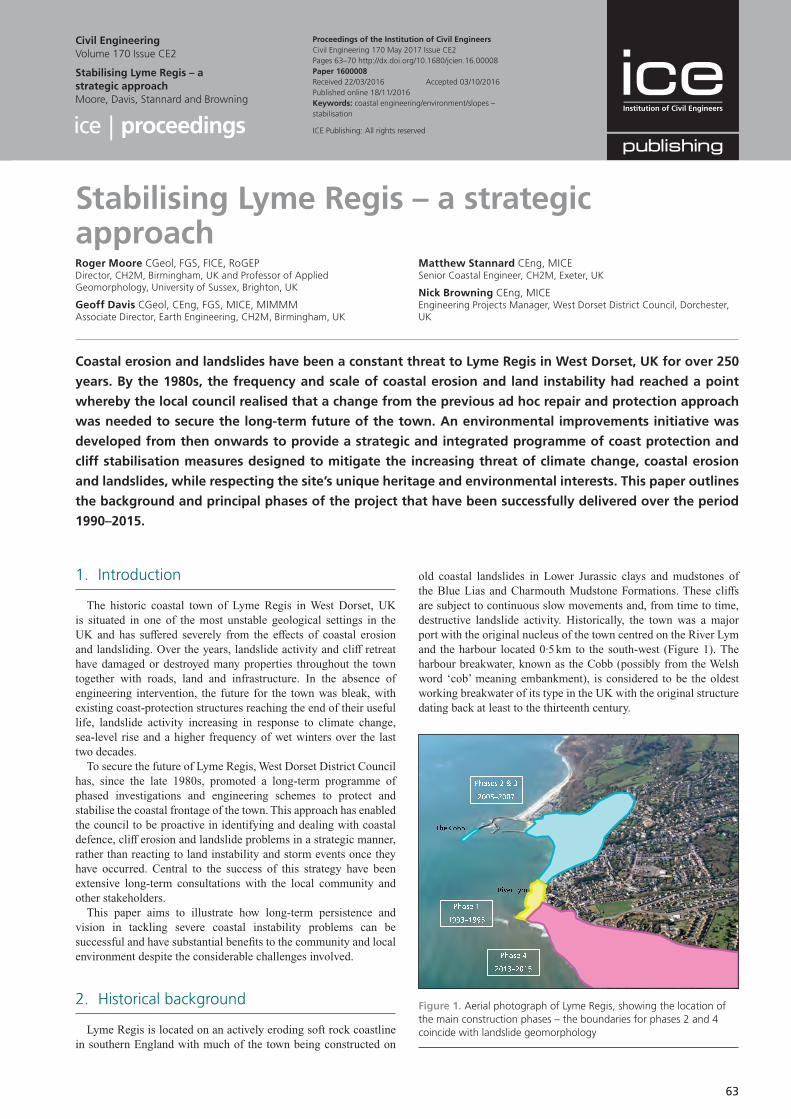
old coastal landslides in Lower Jurassic clays and mudstones of the Blue Lias and Charmouth Mudstone Formations. These cliffs are subject to continuous slow movements and, from time to time, destructive landslide activity. Historically, the town was a major port with the original nucleus of the town centred on the River Lym and the harbour located 0·5 km to the south-west (Figure 1). The harbour breakwater, known as the Cobb (possibly from the Welsh word ‘cob’ meaning embankment), is considered to be the oldest working breakwater of its type in the UK with the original structure dating back at least to the thirteenth century.
1. Introduction
The historic coastal town of Lyme Regis in West Dorset, UK is situated in one of the most unstable geological settings in the UK and has suffered severely from the effects of coastal erosion and landsliding. Over the years, landslide activity and cliff retreat have damaged or destroyed many properties throughout the town together with roads, land and infrastructure. In the absence of engineering intervention, the future for the town was bleak, with existing coast-protection structures reaching the end of their useful life, landslide activity increasing in response to climate change, sea-level rise and a higher frequency of wet winters over the last two decades.
To secure the future of Lyme Regis, West Dorset District Council has, since the late 1980s, promoted a long-term programme of phased investigations and engineering schemes to protect and stabilise the coastal frontage of the town. This approach has enabled the council to be proactive in identifying and dealing with coastal defence, cliff erosion and landslide problems in a strategic manner, rather than reacting to land instability and storm events once they have occurred. Central to the success of this strategy have been extensive long-term consultations with the local community and other stakeholders.
This paper aims to illustrate how long-term persistence and vision in tackling severe coastal instability problems can be successful and have substantial benefits to the community and local environment despite the considerable challenges involved.
2. Historical background
Lyme Regis is located on an actively eroding soft rock coastline in southern England with much of the town being constructed on
Stabilising Lyme Regis – a strategic approachRoger Moore CGeol, FGS, FICE, RoGEPDirector, CH2M, Birmingham, UK and Professor of Applied Geomorphology, University of Sussex, Brighton, UK
Geoff Davis CGeol, CEng, FGS, MICE, MIMMMAssociate Director, Earth Engineering, CH2M, Birmingham, UK
Matthew Stannard CEng, MICESenior Coastal Engineer, CH2M, Exeter, UK
Nick Browning CEng, MICEEngineering Projects Manager, West Dorset District Council, Dorchester, UK
Coastal erosion and landslides have been a constant threat to Lyme Regis in West Dorset, UK for over 250
years. By the 1980s, the frequency and scale of coastal erosion and land instability had reached a point
whereby the local council realised that a change from the previous ad hoc repair and protection approach
was needed to secure the long-term future of the town. An environmental improvements initiative was
developed from then onwards to provide a strategic and integrated programme of coast protection and
cliff stabilisation measures designed to mitigate the increasing threat of climate change, coastal erosion
and landslides, while respecting the site’s unique heritage and environmental interests. This paper outlines
the background and principal phases of the project that have been successfully delivered over the period
1990–2015.
Proceedings of the Institution of Civil EngineersCivil Engineering 170 May 2017 Issue CE2Pages 63–70 http://dx.doi.org/10.1680/jcien.16.00008Paper 1600008Received 22/03/2016 Accepted 03/10/2016Published online 18/11/2016Keywords: coastal engineering/environment/slopes – stabilisation
Civil EngineeringVolume 170 Issue CE2
Stabilising Lyme Regis – a strategic approachMoore, Davis, Stannard and Browning
ICE Publishing: All rights reserved
Figure 1. Aerial photograph of Lyme Regis, showing the location of the main construction phases – the boundaries for phases 2 and 4 coincide with landslide geomorphology
Civil EngineeringVolume 170 Issue CE2
Stabilising Lyme Regis – a strategic approachMoore, Davis, Stannard and Browning
64
■ local emergency works ■ full engineering schemes to stabilise and protect the coastal
areas of the town ■ ongoing extensive consultations with residents, the local
community and other stakeholders.
This holistic, long-term, proactive approach is considered to have many benefits (Brunsden and Moore 1999; Cole et al., 2002; Moore and Davis 2014; Moore et al., 2010). They include
■ the economic case that prevention is better than having to deal with the emergency response and aftermath of destructive erosion or landsliding
■ allowing time and investment to establish a detailed understanding of the problems through phased investigations
■ allowing prioritisation of works for complex sites in order of urgency
■ a phased approach avoids excessive disruption to wide areas of the town
■ delivering economies of scale – the cost of considering the town’s coastline as a whole under a single strategy being less than attempting to deal with individual problem sites in isolation
■ ensuring that schemes are concordant with marine and landslide processes operating on adjacent sections of coastline.
4. Investigations
A wide range of multidisciplinary investigations was carried out in several stages over many years with the findings of the early investigations informing the design of later ones. The main types of investigation and their value are summarised in Table 1. The main findings of the investigations were fundamental to the design and development of coast-protection and cliff-stabilisation schemes. They include the following.
■ Much of town has been built on pre-existing landslides which were active when climatic conditions were worse than at present, for example in late glacial times and during the mediaeval ‘little ice age’. The landslide systems extend up to 500 m inland from the high watermark, which was much further than appreciated previously.
■ The landslides are large, complex, multilayered systems, strongly controlled by geological structure and faulting within the Lower Jurassic clays and mudstones.
■ The existing landslides were prone to rapid reactivation and expansion in the present day due to a combination of marine erosion at the toe, foreshore lowering and the increasing frequency of wet winters.
■ The beaches fronting the town were a small fraction of their former extent, and their size and protective effect has been diminished due to a combination of artificial and natural effects, principally the occurrence of large landslides to the south-west of the town blocking south-eastwards longshore drift.
■ Exacerbated by loss of the beaches, there has been continuing marine erosion at the toe of the landslide systems together with lowering of foreshore ledges.
■ The existing coast-protection structures were deteriorating, with many approaching the end of their useful life.
The original mediaeval town is thought to have extended a considerable distance into what is now the sea. Other than the Cobb, major seawalls in the older parts of the town were not constructed until the 1750s with the seawall between the town centre and the harbour not completed until the 1860s. Where unprotected, the coastline continued to retreat due to a combination of marine erosion and associated landsliding; the materials eroded from the cliffs do not afford much protection in the form of beach-forming materials as the lithology is mostly fine grained. Even in those locations where seawalls were constructed, the landslide systems in the steep and unstable coastal slopes behind continued to retreat inland, causing considerable damage.
The traditional approach to dealing with coastal defence and cliff instability tended to comprise isolated responses to a particular landslide or seawall failure. Previous attempts to stabilise these landslides were not always successful, essentially because the landslide extents and mechanisms were not well understood at that time.
Coastal erosion and landsliding, whilst causing considerable difficulties in the built-up areas of the town, also have some positive aspects. The spectacular scenery on the coasts adjacent to the town is a result of the continuing erosion which also yields abundant fossils. These attractions have meant that tourism is now the town’s principal industry. The importance of the area in terms of geology and geomorphology is recognised internationally through the designation of a Unesco natural world heritage site, commonly known as the Jurassic coast.
3. Strategy
Since the late 1980s, West Dorset District Council has promoted a long-term programme of engineering projects covering the whole of the frontage at Lyme Regis, all within an overarching coastal management strategy. The objective of the strategy has been to provide the town with long-term protection against coastal erosion, landsliding and storms, together with improvements to both the natural and built environments.
The main feature of the strategy was the consideration of the entire landslide system and coastal area of Lyme Regis as a whole. This is in contrast to the traditional piecemeal and reactive approach that often only considers isolated sites or areas which happen to be problematic at the time. The area of interest extended from the top of the coastal slope down to the sea cliffs, intertidal zone and seabed about 1 km offshore as well as coastal areas to the west and east of Lyme Regis. Extensive multidisciplinary investigations, both detailed and wide in scope, were carried out within this area in order to address the relatively complex nature of the coastal erosion and cliff instability problems.
The programme was split into three main phases (Section 5), with each phase typically comprising a range of investigation work and engineering schemes, including
■ desk studies ■ geomorphological and geological mapping of the cliffs,
landslides and beaches ■ phased ground investigations with installation of ground
instrumentation and monitoring ■ preparation of conceptual ground models and process models
for the cliffs and beaches
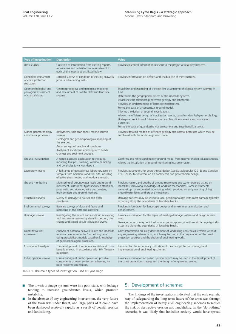
Stabilising Lyme Regis – a strategic approachMoore, Davis, Stannard and Browning
Civil EngineeringVolume 170 Issue CE2
65
5. Development of schemes
The findings of the investigations indicated that the only realistic way of safeguarding the long-term future of the town was through the implementation of heavy civil engineering schemes to reduce the risk of destructive erosion and landsliding. In the ‘do nothing’ scenario, it was likely that landslide activity would have spread
■ The town’s drainage systems were in a poor state, with leakage tending to increase groundwater levels, which promote instability.
■ In the absence of any engineering intervention, the very future of the town was under threat, and large parts of it could have been destroyed relatively rapidly as a result of coastal erosion and landsliding.
Type of investigation Description Value
Desk studies Collation of information from existing reports, repositories and published sources relevant to each of the investigations listed below.
Provides historical information relevant to the project at relatively low cost.
Condition assessment of coast protection structures
External surveys of condition of existing seawalls, jetties and retaining walls.
Provides information on defects and residual life of the structures.
Geomorphological and geological assessment of coastal slopes
Geomorphological and geological mapping and assessment of coastal cliffs and landslide systems.
Establishes understanding of the coastline as a geomorphological system evolving in time.Determines the geographical extent of the landslide systems.Establishes the relationship between geology and landforms.Provides an understanding of landslide mechanisms.Forms the basis of a conceptual ground model.Informs the design of ground investigations.Allows the efficient design of stabilisation works, based on detailed geomorphology.Underpins prediction of future erosion and landslide scenarios and associated outcomes.Forms the basis of quantitative risk assessment and cost–benefit analysis.
Marine geomorphology and coastal processes
Bathymetry, side-scan sonar, marine seismic surveys.Geological and geomorphological mapping of the sea bed.Aerial surveys of beach and foreshore.Analysis of short-term and long-term beach changes and sediment budgets.
Provides detailed models of offshore geology and coastal processes which may be combined with the onshore ground model.
Ground investigation A range a ground exploration techniques, including trial pits, probing, window sampling and boreholes to various depths.
Confirms and refines preliminary ground model from geomorphological assessments.Allows the installation of ground-monitoring instrumentation.
Laboratory testing A full range of geotechnical laboratory tests on samples from boreholes and trial pits, including effective stress testing and residual strength.
Provides parameters for geotechnical design (see Daskalopoulos (2015) and Candian et al. (2015) for information on parameters and geotechnical design).
Ground monitoring Monitoring of groundwater levels and ground movement. Instrument types included standpipe, pneumatic and vibrating wire piezometers; inclinometers and ground markers.
Provides vectors and depths of ground movement and water pressure acting on landslides, improving knowledge of landslide mechanisms. Some instruments were set up for automated monitoring, which provided an early warning of high groundwater levels and ground movement.
Structural surveys Survey of damage to houses and other structures.
Damage patterns may be linked to local geomorphology, with most damage typically occurring along the boundaries of landslide blocks.
Environmental surveys Baseline surveys of flora and fauna and landscape of the cliffs and coastline.
Provides information for landscape design and environmental mitigation and enhancement.
Drainage surveys Investigating the extent and condition of existing foul and storm systems by visual inspection, dye testing and closed-circuit television surveys.
Provides information for the repair of existing drainage systems and design of new ones.Damage patterns may be linked to local geomorphology, with most damage typically occurring along the boundaries of landslide blocks.
Quantitative risk assessment
Analysis of potential seawall failure and landslide recession scenarios in the ‘do nothing case’, using probabilistic models based on knowledge of geomorphological processes.
Gives information on likely development of landsliding and coastal erosion without any engineering intervention, which may be used in the preparation of the coast protection strategy and the design of engineering works.
Cost–benefit analysis The development of economic models and cost–benefit analysis, in accordance with HM Treasury guidelines.
Required for the economic justification of the coast protection strategy and implementation of engineering schemes.
Public opinion surveys Formal surveys of public opinion on possible components of coast protection schemes, for both residents and visitors.
Provides information on public opinion, which may be used in the development of the coast protection strategy and the design of engineering works.
Table 1. The main types of investigation used at Lyme Regis
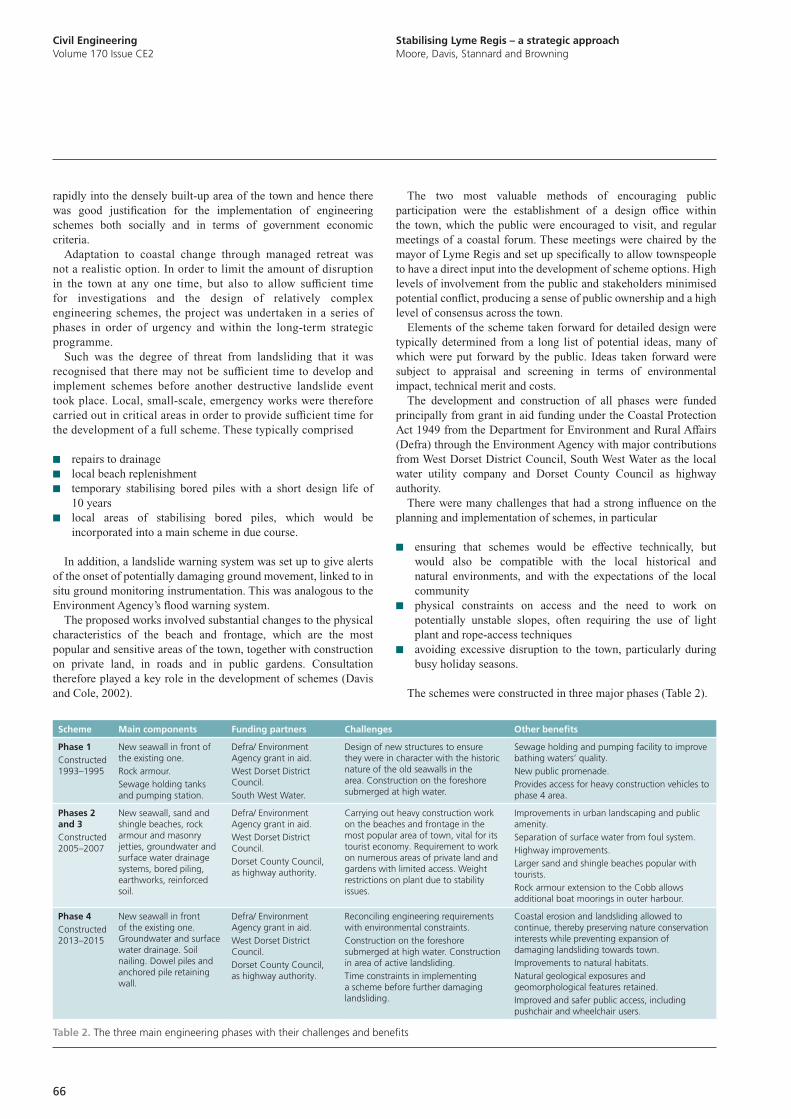
Civil EngineeringVolume 170 Issue CE2
Stabilising Lyme Regis – a strategic approachMoore, Davis, Stannard and Browning
66
The two most valuable methods of encouraging public participation were the establishment of a design office within the town, which the public were encouraged to visit, and regular meetings of a coastal forum. These meetings were chaired by the mayor of Lyme Regis and set up specifically to allow townspeople to have a direct input into the development of scheme options. High levels of involvement from the public and stakeholders minimised potential conflict, producing a sense of public ownership and a high level of consensus across the town.
Elements of the scheme taken forward for detailed design were typically determined from a long list of potential ideas, many of which were put forward by the public. Ideas taken forward were subject to appraisal and screening in terms of environmental impact, technical merit and costs.
The development and construction of all phases were funded principally from grant in aid funding under the Coastal Protection Act 1949 from the Department for Environment and Rural Affairs (Defra) through the Environment Agency with major contributions from West Dorset District Council, South West Water as the local water utility company and Dorset County Council as highway authority.
There were many challenges that had a strong influence on the planning and implementation of schemes, in particular
■ ensuring that schemes would be effective technically, but would also be compatible with the local historical and natural environments, and with the expectations of the local community
■ physical constraints on access and the need to work on potentially unstable slopes, often requiring the use of light plant and rope-access techniques
■ avoiding excessive disruption to the town, particularly during busy holiday seasons.
The schemes were constructed in three major phases (Table 2).
rapidly into the densely built-up area of the town and hence there was good justification for the implementation of engineering schemes both socially and in terms of government economic criteria.
Adaptation to coastal change through managed retreat was not a realistic option. In order to limit the amount of disruption in the town at any one time, but also to allow sufficient time for investigations and the design of relatively complex engineering schemes, the project was undertaken in a series of phases in order of urgency and within the long-term strategic programme.
Such was the degree of threat from landsliding that it was recognised that there may not be sufficient time to develop and implement schemes before another destructive landslide event took place. Local, small-scale, emergency works were therefore carried out in critical areas in order to provide sufficient time for the development of a full scheme. These typically comprised
■ repairs to drainage ■ local beach replenishment ■ temporary stabilising bored piles with a short design life of
10 years ■ local areas of stabilising bored piles, which would be
incorporated into a main scheme in due course.
In addition, a landslide warning system was set up to give alerts of the onset of potentially damaging ground movement, linked to in situ ground monitoring instrumentation. This was analogous to the Environment Agency’s flood warning system.
The proposed works involved substantial changes to the physical characteristics of the beach and frontage, which are the most popular and sensitive areas of the town, together with construction on private land, in roads and in public gardens. Consultation therefore played a key role in the development of schemes (Davis and Cole, 2002).
Scheme Main components Funding partners Challenges Other benefits
Phase 1Constructed 1993–1995
New seawall in front of the existing one.Rock armour.Sewage holding tanks and pumping station.
Defra/ Environment Agency grant in aid.West Dorset District Council.South West Water.
Design of new structures to ensure they were in character with the historic nature of the old seawalls in the area. Construction on the foreshore submerged at high water.
Sewage holding and pumping facility to improve bathing waters’ quality.New public promenade.Provides access for heavy construction vehicles to phase 4 area.
Phases 2 and 3Constructed 2005–2007
New seawall, sand and shingle beaches, rock armour and masonry jetties, groundwater and surface water drainage systems, bored piling, earthworks, reinforced soil.
Defra/ Environment Agency grant in aid.West Dorset District Council.Dorset County Council, as highway authority.
Carrying out heavy construction work on the beaches and frontage in the most popular area of town, vital for its tourist economy. Requirement to work on numerous areas of private land and gardens with limited access. Weight restrictions on plant due to stability issues.
Improvements in urban landscaping and public amenity.Separation of surface water from foul system.Highway improvements.Larger sand and shingle beaches popular with tourists.Rock armour extension to the Cobb allows additional boat moorings in outer harbour.
Phase 4Constructed 2013–2015
New seawall in front of the existing one. Groundwater and surface water drainage. Soil nailing. Dowel piles and anchored pile retaining wall.
Defra/ Environment Agency grant in aid.West Dorset District Council.Dorset County Council, as highway authority.
Reconciling engineering requirements with environmental constraints.Construction on the foreshore submerged at high water. Construction in area of active landsliding.Time constraints in implementing a scheme before further damaging landsliding.
Coastal erosion and landsliding allowed to continue, thereby preserving nature conservation interests while preventing expansion of damaging landsliding towards town.Improvements to natural habitats.Natural geological exposures and geomorphological features retained.Improved and safer public access, including pushchair and wheelchair users.
Table 2. The three main engineering phases with their challenges and benefits
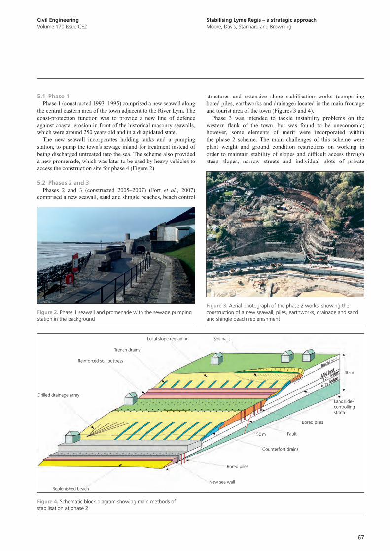
Stabilising Lyme Regis – a strategic approachMoore, Davis, Stannard and Browning
Civil EngineeringVolume 170 Issue CE2
67
structures and extensive slope stabilisation works (comprising bored piles, earthworks and drainage) located in the main frontage and tourist area of the town (Figures 3 and 4).
Phase 3 was intended to tackle instability problems on the western flank of the town, but was found to be uneconomic; however, some elements of merit were incorporated within the phase 2 scheme. The main challenges of this scheme were plant weight and ground condition restrictions on working in order to maintain stability of slopes and difficult access through steep slopes, narrow streets and individual plots of private
5.1 Phase 1Phase 1 (constructed 1993–1995) comprised a new seawall along
the central eastern area of the town adjacent to the River Lym. The coast-protection function was to provide a new line of defence against coastal erosion in front of the historical masonry seawalls, which were around 250 years old and in a dilapidated state.
The new seawall incorporates holding tanks and a pumping station, to pump the town’s sewage inland for treatment instead of being discharged untreated into the sea. The scheme also provided a new promenade, which was later to be used by heavy vehicles to access the construction site for phase 4 (Figure 2).
5.2 Phases 2 and 3Phases 2 and 3 (constructed 2005–2007) (Fort et al., 2007)
comprised a new seawall, sand and shingle beaches, beach control
Figure 3. Aerial photograph of the phase 2 works, showing the construction of a new seawall, piles, earthworks, drainage and sand and shingle beach replenishment
Figure 2. Phase 1 seawall and promenade with the sewage pumping station in the background
Local slope regrading Soil nails
Trench drains
Reinforced soil buttress
Drilled drainage array
Replenished beach
New sea wall
Bored piles
Counterfort drains
Fault
Bored piles
150 m
40 m
Landslide-controlling strata
Birchi bed
Mid bed
Table ledge
Grey ledge
Figure 4. Schematic block diagram showing main methods of stabilisation at phase 2
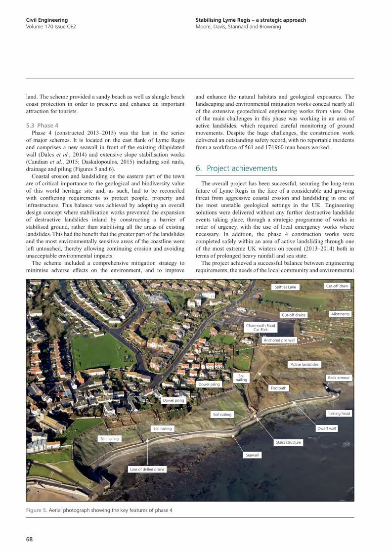
Civil EngineeringVolume 170 Issue CE2
Stabilising Lyme Regis – a strategic approachMoore, Davis, Stannard and Browning
68
and enhance the natural habitats and geological exposures. The landscaping and environmental mitigation works conceal nearly all of the extensive geotechnical engineering works from view. One of the main challenges in this phase was working in an area of active landslides, which required careful monitoring of ground movements. Despite the huge challenges, the construction work delivered an outstanding safety record, with no reportable incidents from a workforce of 561 and 174 960 man hours worked.
6. Project achievements
The overall project has been successful, securing the long-term future of Lyme Regis in the face of a considerable and growing threat from aggressive coastal erosion and landsliding in one of the most unstable geological settings in the UK. Engineering solutions were delivered without any further destructive landslide events taking place, through a strategic programme of works in order of urgency, with the use of local emergency works where necessary. In addition, the phase 4 construction works were completed safely within an area of active landsliding through one of the most extreme UK winters on record (2013–2014) both in terms of prolonged heavy rainfall and sea state.
The project achieved a successful balance between engineering requirements, the needs of the local community and environmental
land. The scheme provided a sandy beach as well as shingle beach coast protection in order to preserve and enhance an important attraction for tourists.
5.3 Phase 4Phase 4 (constructed 2013–2015) was the last in the series
of major schemes. It is located on the east flank of Lyme Regis and comprises a new seawall in front of the existing dilapidated wall (Dales et al., 2014) and extensive slope stabilisation works (Candian et al., 2015; Daskalopoulos, 2015) including soil nails, drainage and piling (Figures 5 and 6).
Coastal erosion and landsliding on the eastern part of the town are of critical importance to the geological and biodiversity value of this world heritage site and, as such, had to be reconciled with conflicting requirements to protect people, property and infrastructure. This balance was achieved by adopting an overall design concept where stabilisation works prevented the expansion of destructive landslides inland by constructing a barrier of stabilised ground, rather than stabilising all the areas of existing landslides. This had the benefit that the greater part of the landslides and the most environmentally sensitive areas of the coastline were left untouched, thereby allowing continuing erosion and avoiding unacceptable environmental impacts.
The scheme included a comprehensive mitigation strategy to minimise adverse effects on the environment, and to improve
Soil nailing
Soil nailing
Soil nailing
Soil nailing
Dowel piling
Dowel piling
Stairs structure
Active landslides
Cut-off drains
Spittles Lane Cut-off drain
Allotments
Anchored pile wall
Charmouth Road Car Park
Line of drilled drains
Seawall
Dwarf wall
Turning head
Footpath
Rock armour
Figure 5. Aerial photograph showing the key features of phase 4
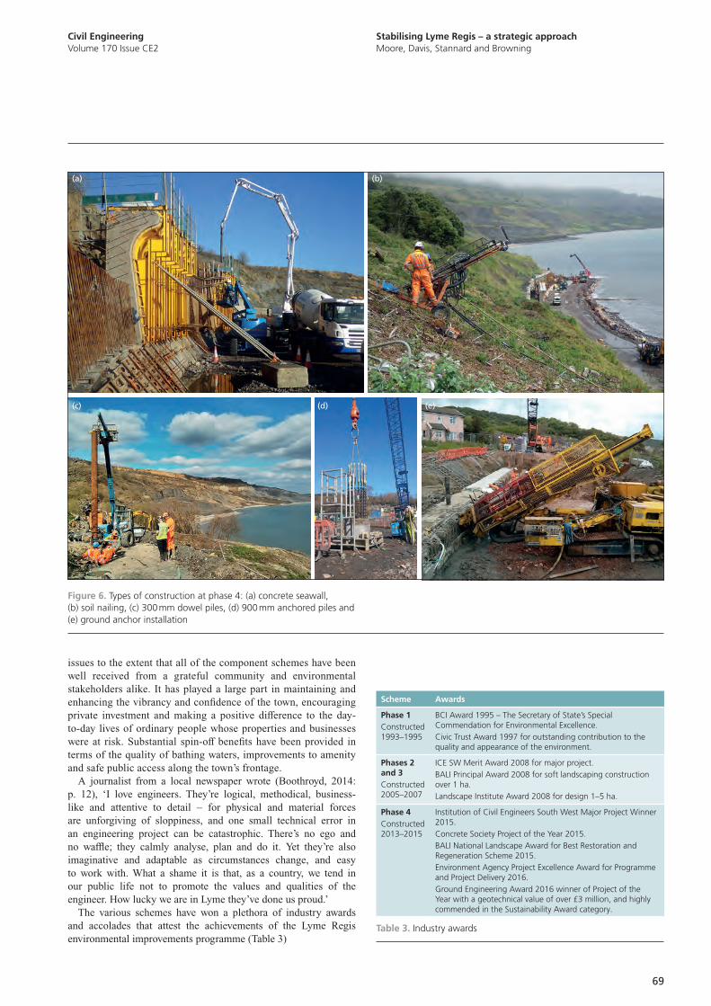
Stabilising Lyme Regis – a strategic approachMoore, Davis, Stannard and Browning
Civil EngineeringVolume 170 Issue CE2
69
issues to the extent that all of the component schemes have been well received from a grateful community and environmental stakeholders alike. It has played a large part in maintaining and enhancing the vibrancy and confidence of the town, encouraging private investment and making a positive difference to the day-to-day lives of ordinary people whose properties and businesses were at risk. Substantial spin-off benefits have been provided in terms of the quality of bathing waters, improvements to amenity and safe public access along the town’s frontage.
A journalist from a local newspaper wrote (Boothroyd, 2014: p. 12), ‘I love engineers. They’re logical, methodical, business-like and attentive to detail – for physical and material forces are unforgiving of sloppiness, and one small technical error in an engineering project can be catastrophic. There’s no ego and no waffle; they calmly analyse, plan and do it. Yet they’re also imaginative and adaptable as circumstances change, and easy to work with. What a shame it is that, as a country, we tend in our public life not to promote the values and qualities of the engineer. How lucky we are in Lyme they’ve done us proud.’
The various schemes have won a plethora of industry awards and accolades that attest the achievements of the Lyme Regis environmental improvements programme (Table 3)
Scheme Awards
Phase 1Constructed 1993–1995
BCI Award 1995 – The Secretary of State’s Special Commendation for Environmental Excellence.Civic Trust Award 1997 for outstanding contribution to the quality and appearance of the environment.
Phases 2 and 3Constructed 2005–2007
ICE SW Merit Award 2008 for major project.BALI Principal Award 2008 for soft landscaping construction over 1 ha.Landscape Institute Award 2008 for design 1–5 ha.
Phase 4Constructed 2013–2015
Institution of Civil Engineers South West Major Project Winner 2015.Concrete Society Project of the Year 2015.BALI National Landscape Award for Best Restoration and Regeneration Scheme 2015.Environment Agency Project Excellence Award for Programme and Project Delivery 2016.Ground Engineering Award 2016 winner of Project of the Year with a geotechnical value of over £3 million, and highly commended in the Sustainability Award category.
Table 3. Industry awards
(a)
(c) (d) (e)
(b)
Figure 6. Types of construction at phase 4: (a) concrete seawall, (b) soil nailing, (c) 300 mm dowel piles, (d) 900 mm anchored piles and (e) ground anchor installation
Civil EngineeringVolume 170 Issue CE2
Stabilising Lyme Regis – a strategic approachMoore, Davis, Stannard and Browning
70
Acknowledgements
The authors acknowledge the contributions of the many organisations and individuals involved in the development of the project since the late 1980s. West Dorset District Council is the client for the project and the scheme promotor. CH2M is the client’s consulting engineer. Balfour Beatty and Aecom were the design-and-build contractor and designer, respectively, on phase 4. High-Point Rendel led the investigation and design in the early phases. The project has been funded by Environment Agency/Defra grant in aid under the Coast Protection Act 1949, by West Dorset District Council and by Dorset County Council in their role as highway authority. The authors are grateful for the support of colleagues on the project over many years particularly Keith Cole, Denys Brunsden, Alan Clark and Steve Fort.
7. Lessons learned
The strategic, long-term approach was found to have many benefits in addition to the economic case that prevention is better than cure. For example, considering the whole of the Lyme Regis coastline as part of the strategy yielded a deeper understanding of land instability and coastal erosion mechanisms than could have been gained from the study of isolated problem areas alone. It also allowed the determination of the very best coast-protection management options and the optimum programme for their implementation.
The direct involvement of the public and stakeholders in the development of schemes over many years was an essential part of the strategy, and a big contributor to the success and popularity of the schemes. However, the practical implementation of construction works needed to be carefully managed to avoid excessive disruption to the busy town with difficult site access. If poorly planned and managed, the construction works themselves could have been so disruptive and damaging to the town that public support would have been lost.
On the technical side, the design of the stabilisation works was found to be critically dependent on the fine detail of the geology and geomorphology, such as positions of small faults and individual thin strata. A detailed conceptual ground model (Sellwood et al., 2000), built up through several stages of ground investigation, was an essential basis for the design of an effective engineering scheme. The use of geomorphological techniques (Brunsden, 2002) formed a continuous thread throughout the implementation of the project, from identifying the nature and extent of the problem in the first place, assessing the consequences of doing nothing, informing the business case and through to the detailed design of the stabilisation works. The ground conditions encountered during construction were found to be very close to the conceptual ground models developed during the investigation stages.
Finally, there is often a rather pessimistic attitude from some quarters that, however hard the engineering community works on protecting a town from coastal erosion, it is ultimately doomed to failure because ‘it is unsustainable’ and ‘nature will always win in the end’. However, the Lyme Regis project has demonstrated that it is possible to protect a town against natural processes while still enhancing the natural environment. The project may be thought of as the latest in a long line of schemes since construction of the Cobb, which together have maintained the viability of the town for at least the last 800 years.
8. Conclusion
It is considered that there would be great benefits in using the coastal instability and erosion management methodologies applied to the Lyme Regis scheme in future projects facing similar challenges.
There are many locations in the UK and internationally where coastal erosion and landsliding in soft rock cliffs are threatening communities and where there are also considerable environmental constraints and opportunities.
Employing the philosophies outlined in this paper could make the difference between protecting a community and allowing a town to be destroyed by natural processes.
References
Boothroyd C (2014) Continuing a fine tradition. View from Lyme Regis, issue 403, 12 February.
Brunsden D (2002) The Fifth Glossop Lecture – Geomorphological roulette for engineers and planners: some insights into an old game. Quarterly Journal of Engineering Geology and Hydrogeology 35(2): 101–142.
Brunsden D and Moore R (1999) Engineering geomorphology on the coast: lessons from West Dorset. Geomorphology 31(1–4): 391–409.
Candian C, Goodwin A and Daskalopoulos DG (2015) The design of an anchored pile retaining structure to control landslide regression at Lyme Regis, UK. In Geotechnical Engineering for Infrastructure and Development: XVI European Conference on Soil Mechanics and Geotechnical Engineering (Winter MG, Smith DM, Eldred PJL and Toll DG (eds)). ICE Publishing, London, UK, pp. 1759–1794.
Coastal Protection Act 1949. George VI. Chapter 74. His Majesty’s Stationery Office, London, UK.
Cole K, Davis G, Clark AR and Fort DS (2002) Managing coastal instability – a holistic approach. In Instability – Planning and Management (McInnes RG and Jakeways J (eds)). Thomas Telford, London, UK, pp. 679–686.
Dales D, Hein R, Hill C and Browning N (2014) Lyme Regis environmental improvements phase IV. In From Sea to Shore – Meeting the Challenges of the Sea: Coasts, Marine Structures and Breakwaters 2013 (Allsop W and Burgess K (eds)). ICE Publishing, London, UK, pp. 783–793.
Daskalopoulos DG (2015) The use of slope stabilising piles and soil nailing to stabilise part of a large landslide complex at Lyme Regis, UK. In Geotechnical Engineering for Infrastructure and Development: XVI European Conference on Soil Mechanics and Geotechnical Engineering (Winter MG, Smith DM, Eldred PJL and Toll DG (eds)). ICE Publishing, London, UK, pp 1737–1742.
Davis GM and Cole K (2002) Working with the community – public liaison in instability management at Lyme Regis, Dorset, England. In Instability – Planning and Management (McInnes RG and Jakeways J (eds)). Thomas Telford, London, UK, pp. 695–700.
Fort DS, Martin, PL, Clark, AR and Davis GM (2007) Lyme Regis phase II coast protection and slope stabilisation scheme, Dorset, UK – the influence of climate change on design. In Landslides and Climate Change: Challenges and Solutions (McInnes R, Jakeways J, Fairbank H and Mathie E (eds)). Taylor and Francis, London, UK, pp. 419–428.
Moore R and Davis GM (2014) Cliff instability and erosion management in England and Wales. Journal of Coastal Conservation 19(6): 771–784.
Moore R, Rogers J, Woodget A and Baptiste A (2010) Climate change impact on cliff instability and erosion in the UK. Proceedings of the 45th Environment Agency Conference of River and Coastal Engineers, Telford, UK.
Sellwood M, Davis GM, Brunsden D and Moore R (2000) Ground models for the coastal landslides at Lyme Regis Dorset, UK. In Landslides in Research, Theory and Practice (Bromhead E, Dixon N and Ibsen ML (eds)). Thomas Telford, London, UK, vol. 3, pp. 1361–1366.
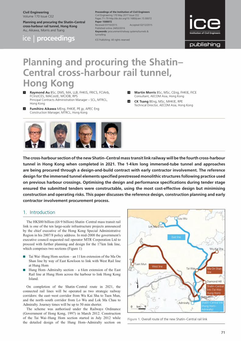
71
1. Introduction
The HK$80 billion (£6·9 billion) Shatin–Central mass transit rail link is one of the ten large-scale infrastructure projects announced by the chief executive of the Hong Kong Special Administrative Region in his 2007/8 policy address. In mid-2008 the government’s executive council requested rail operator MTR Corporation Ltd to proceed with further planning and design for the 17 km link line, which comprises two sections (Figure 1)
■ Tai Wai–Hung Hom section – an 11 km extension of the Ma On Shan line by way of East Kowloon to link with West Rail line at Hung Hom
■ Hung Hom–Admiralty section – a 6 km extension of the East Rail line at Hung Hom across the harbour to link Hong Kong Island.
On completion of the Shatin–Central route in 2021, the connected rail lines will be operated as two strategic railway corridors: the east–west corridor from Wu Kai Sha to Tuen Mun, and the north–south corridor from Lo Wu and Lok Ma Chau to Admiralty. Journey times will be up to 50 min shorter.
The scheme was authorised under the Railways Ordinance (Government of Hong Kong, 1997) in March 2012. Construction of the Tai Wai–Hung Hom section started in July 2012 while the detailed design of the Hung Hom–Admiralty section on
Planning and procuring the Shatin–Central cross-harbour rail tunnel, Hong Kong1 Raymond Au BSc, DMS, MA, LLB, FHKIS, FRICS, FCIArb,
FCInstCES, MACostE, MCIOB, RPSPrincipal Contracts Administration Manager – SCL, MTRCL, Hong Kong
2 Fumihiro Aikawa MEng, FHKIE, PE jp, APEC EngConstruction Manager, MTRCL, Hong Kong
3 Martin Morris BSc, MSc, CEng, FHKIE, FICEConsultant, AECOM Asia, Hong Kong
4 CK Tsang BEng, MSc, MHKIE, RPETechnical Director, AECOM Asia, Hong Kong
The cross-harbour section of the new Shatin–Central mass transit link railway will be the fourth cross-harbour
tunnel in Hong Kong when completed in 2021. The 1·4 km long immersed-tube tunnel and approaches
are being procured through a design-and-build contract with early contractor involvement. The reference
design for the immersed tunnel elements specified prestressed monolithic structures following practice used
on previous harbour crossings. Optimising the design and performance specifications during tender stage
ensured the submitted tenders were constructable, using the most cost-effective design but minimising
construction and operating risks. This paper discusses the reference design, construction planning and early
contractor involvement procurement process.
Proceedings of the Institution of Civil EngineersCivil Engineering 170 May 2017 Issue CE2Pages 71–79 http://dx.doi.org/10.1680/jcien.15.00072Paper 1500072Received 07/10/2015 Accepted 02/12/2015Published online 24/02/2016Keywords: procurement/railway systems/tunnels & tunnelling
Civil EngineeringVolume 170 Issue CE2
Planning and procuring the Shatin–Central cross-harbour rail tunnel, Hong KongAu, Aikawa, Morris and Tsang
ICE Publishing: All rights reserved
1 2 3 4
Diamond Hill
Tai Wai
Wu Kai Sha
Lou Wu
Lok Ma Chau
Hung Hom
Admiralty
Tuen Mun
Shatin–Central link (Tai Wai– Hung Hom)
Ma On Shan line
West line
East line
Shatin–Central link (Hung Hom– Admiralty)
km 60
Figure 1. Overall route of the new Shatin–Central rail link
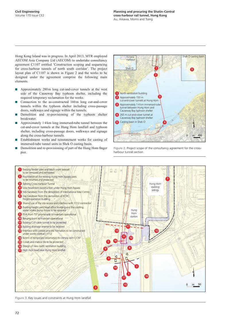
Civil EngineeringVolume 170 Issue CE2
Planning and procuring the Shatin–Central cross-harbour rail tunnel, Hong KongAu, Aikawa, Morris and Tsang
72
Hong Kong Island was in progress. In April 2013, MTR employed AECOM Asia Company Ltd (AECOM) to undertake consultancy agreement C1107 entitled ‘Construction scoping and sequencing for cross-harbour tunnels of north south corridor’. The project layout plan of C1107 is shown in Figure 2 and the works to be designed under the agreement comprise the following main elements.
■ Approximately 280 m long cut-and-cover tunnels at the west side of the Causeway Bay typhoon shelter, including the required temporary reclamation for the works.
■ Connection to the as-constructed 160 m long cut-and-cover tunnels within the typhoon shelter including cross-passage doors, walkways and signage within the tunnels.
■ Demolition and re-provisioning of the typhoon shelter breakwater.
■ Approximately 1·4 km long immersed-tube tunnel between the cut-and-cover tunnels at the Hung Hom landfall and typhoon shelter, including cross-passage doors, walkways and signage along the cross-harbour tunnels.
■ Establishment works and reinstatement works for casting of immersed-tube tunnel units in Shek O casting basin.
■ Demolition and re-provisioning of part of the Hung Hom finger pier.
North ventilation building
Approximately 150 m cut-and-cover tunnels at Hung Hom
Approximately 1.4 km immersed-tube tunnel between Hung Hom andCauseway Bay typhoon shelter
265 m cut-and-cover tunnel at Causeway Bay typhoon shelter
Casting basin in Shek O
Victoria Harbour
Shek O
Shek O casting basin
2
3
4
51
1
2
3
4
5
m 4000
Figure 2. Project scope of the consultancy agreement for the cross-harbour tunnel section
Hung Homstablingsidings
HungHom
station
Existing fender piles and block-work seawall to be removed and reinstated
Foundation of the existing Hung Hom bypass piers to be retained and protected
Existing Cross Harbour Tunnel
Low headroom construction under Hung Hom bypass
Site handover from the demolition of International Mail Centre
Site handover from the demolition of KCRC freight operation building
Shared use of the site access and interface with 1112 contractor
Existing freight yard head office building and the coolling water intake pump house to be retained
EVA from TST promenade to maintain operational
Barging point to maintain operational
Existing CLP cable tunnel to be protected
Existing drainage reserve to be retained
Interface with utilities and site formation to be constructed under works contract 1112
Extent of temporary reclamation to comply with CCM
Corals and marine life to be protected
Design of new north ventilation building
High rock head near Hung Hom landfall
1
2
3
4
7
8
5
6
9
10
11
12
14
13
15
16
17
1717
17
14
1
2
4
89
5 1612
12
7
13
11
6
153
10
m 500
Figure 3. Key issues and constraints at Hung Hom landfall
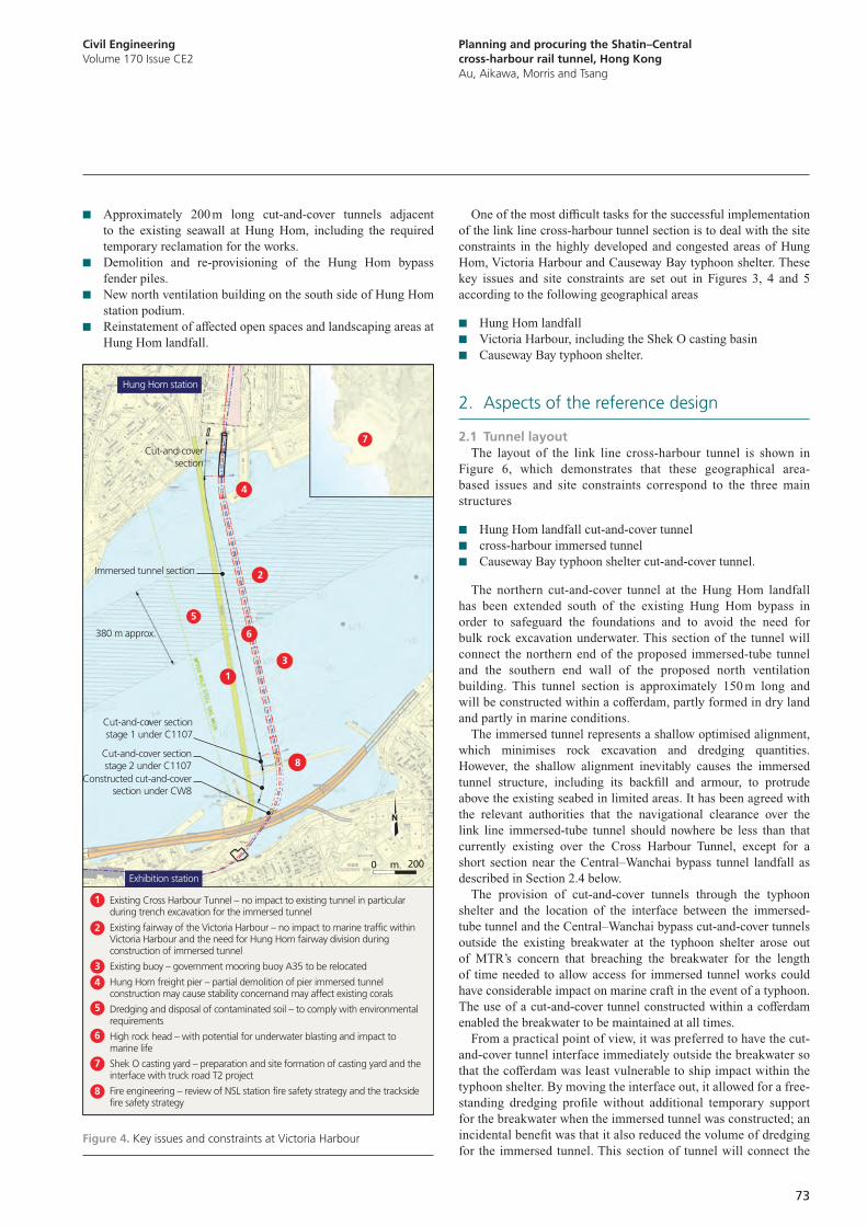
Planning and procuring the Shatin–Central cross-harbour rail tunnel, Hong KongAu, Aikawa, Morris and Tsang
Civil EngineeringVolume 170 Issue CE2
73
One of the most difficult tasks for the successful implementation of the link line cross-harbour tunnel section is to deal with the site constraints in the highly developed and congested areas of Hung Hom, Victoria Harbour and Causeway Bay typhoon shelter. These key issues and site constraints are set out in Figures 3, 4 and 5 according to the following geographical areas
■ Hung Hom landfall ■ Victoria Harbour, including the Shek O casting basin ■ Causeway Bay typhoon shelter.
2. Aspects of the reference design
2.1 Tunnel layoutThe layout of the link line cross-harbour tunnel is shown in
Figure 6, which demonstrates that these geographical area-based issues and site constraints correspond to the three main structures
■ Hung Hom landfall cut-and-cover tunnel ■ cross-harbour immersed tunnel ■ Causeway Bay typhoon shelter cut-and-cover tunnel.
The northern cut-and-cover tunnel at the Hung Hom landfall has been extended south of the existing Hung Hom bypass in order to safeguard the foundations and to avoid the need for bulk rock excavation underwater. This section of the tunnel will connect the northern end of the proposed immersed-tube tunnel and the southern end wall of the proposed north ventilation building. This tunnel section is approximately 150 m long and will be constructed within a cofferdam, partly formed in dry land and partly in marine conditions.
The immersed tunnel represents a shallow optimised alignment, which minimises rock excavation and dredging quantities. However, the shallow alignment inevitably causes the immersed tunnel structure, including its backfill and armour, to protrude above the existing seabed in limited areas. It has been agreed with the relevant authorities that the navigational clearance over the link line immersed-tube tunnel should nowhere be less than that currently existing over the Cross Harbour Tunnel, except for a short section near the Central–Wanchai bypass tunnel landfall as described in Section 2.4 below.
The provision of cut-and-cover tunnels through the typhoon shelter and the location of the interface between the immersed-tube tunnel and the Central–Wanchai bypass cut-and-cover tunnels outside the existing breakwater at the typhoon shelter arose out of MTR’s concern that breaching the breakwater for the length of time needed to allow access for immersed tunnel works could have considerable impact on marine craft in the event of a typhoon. The use of a cut-and-cover tunnel constructed within a cofferdam enabled the breakwater to be maintained at all times.
From a practical point of view, it was preferred to have the cut-and-cover tunnel interface immediately outside the breakwater so that the cofferdam was least vulnerable to ship impact within the typhoon shelter. By moving the interface out, it allowed for a free-standing dredging profile without additional temporary support for the breakwater when the immersed tunnel was constructed; an incidental benefit was that it also reduced the volume of dredging for the immersed tunnel. This section of tunnel will connect the
■ Approximately 200 m long cut-and-cover tunnels adjacent to the existing seawall at Hung Hom, including the required temporary reclamation for the works.
■ Demolition and re-provisioning of the Hung Hom bypass fender piles.
■ New north ventilation building on the south side of Hung Hom station podium.
■ Reinstatement of affected open spaces and landscaping areas at Hung Hom landfall.
Cut-and-coversection
380 m approx.
Immersed tunnel section
Hung Hom station
Exhibition station
Cut-and-cover sectionstage 1 under C1107
Cut-and-cover sectionstage 2 under C1107
Constructed cut-and-coversection under CW8
1
1
2
2
3
5
4
3
7
7
8
8
5
4
6
6
Existing Cross Harbour Tunnel – no impact to existing tunnel in particular during trench excavation for the immersed tunnel
Existing fairway of the Victoria Harbour – no impact to marine traffic within Victoria Harbour and the need for Hung Hom fairway division during construction of immersed tunnel
Existing buoy – government mooring buoy A35 to be relocated
Hung Hom freight pier – partial demolition of pier immersed tunnel construction may cause stability concernand may affect existing corals
Dredging and disposal of contaminated soil – to comply with environmental requirements
High rock head – with potential for underwater blasting and impact to marine life
Shek O casting yard – preparation and site formation of casting yard and the interface with truck road T2 project
Fire engineering – review of NSL station fire safety strategy and the trackside fire safety strategy
m 2000
Figure 4. Key issues and constraints at Victoria Harbour
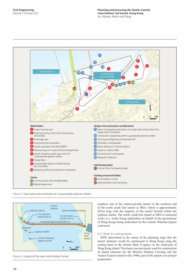
Civil EngineeringVolume 170 Issue CE2
Planning and procuring the Shatin–Central cross-harbour rail tunnel, Hong KongAu, Aikawa, Morris and Tsang
74
southern end of the immersed-tube tunnel to the northern end of the north–south line tunnel at ME4, which is approximately 265 m long with the majority of the tunnel formed within the typhoon shelter. The north–south line tunnel at ME4 is entrusted works (i.e. works being undertaken on behalf of the government of Hong Kong) being undertaken by the Central–Wanchai bypass contractor.
2.2 Shek O casting basinMTR determined at the outset of the planning stage that the
tunnel elements would be constructed in Hong Kong using the casting basin at the former Shek O quarry in the south-east of Hong Kong Island. This basin was previously used for construction of tunnel elements for the Western Harbour Crossing and the Airport Express tunnel in the 1990s, part of the airport core project programme.
1
2
3
4
5
6
7
8
9
10
13
14
15
16
17
18
19
20
22
23
22
23
21
13
14 15
16
17
18
18
19 20
21
11
12
1
2
3
45
6
7
8
910 11
12
Private mooring area
Royal Hong Kong Yacht Club mooring area and facilities
Anchorage area
Hong Kong Pilot Association
Vessels associated with MEAL/MBTA
Mooring buoys of Customs & Excise Department
Vessels moored at south west corner of Causeway Bay typhoon shelter
Temple Boat
Causeway Bay Typhoon Shelter Mutual Aid Committee
Hong Kong Off-shore Fisherman’s Association
Communication with all stakeholders
Marine Department
Extent of temporary reclamation to comply with Central–Wan Chai bypass and CCM reports
Construction sequencing within Causeway Bay typhoon shelter
Sourcing and disposing of reclamation fill
Demolition of breakwater
Wave reflection to Victoria Harbour
Impact to marine traffic
Cut-and-cover tunnel section
Disposal of sediment
Central–Wan Chai bypass project
Cross Harbour Tunnel
Instrumentation and monitoring
Stakeholders Design and construction considerations
Interfacing project
Existing structure/facilitiesLiaison
Victoria Harbour
Causeway Bay
Causeway Baytyphoon shelter
m 1000
Figure 5. Key issues and constraints at Causeway Bay typhoon shelter
ME4 (by others)
Cut-and-cover tunnel (265 m) Cut-and-cover
tunnel (150 m)
Central–Wanchai bypass tunnels
Typhoon shelter
VictoriaHarbour
CausewayBay
North ventilation building
HungHomstation
Immersed tube tunnel (1335 m)
m 4000
Figure 6. Layout of the new cross-harbour tunnel
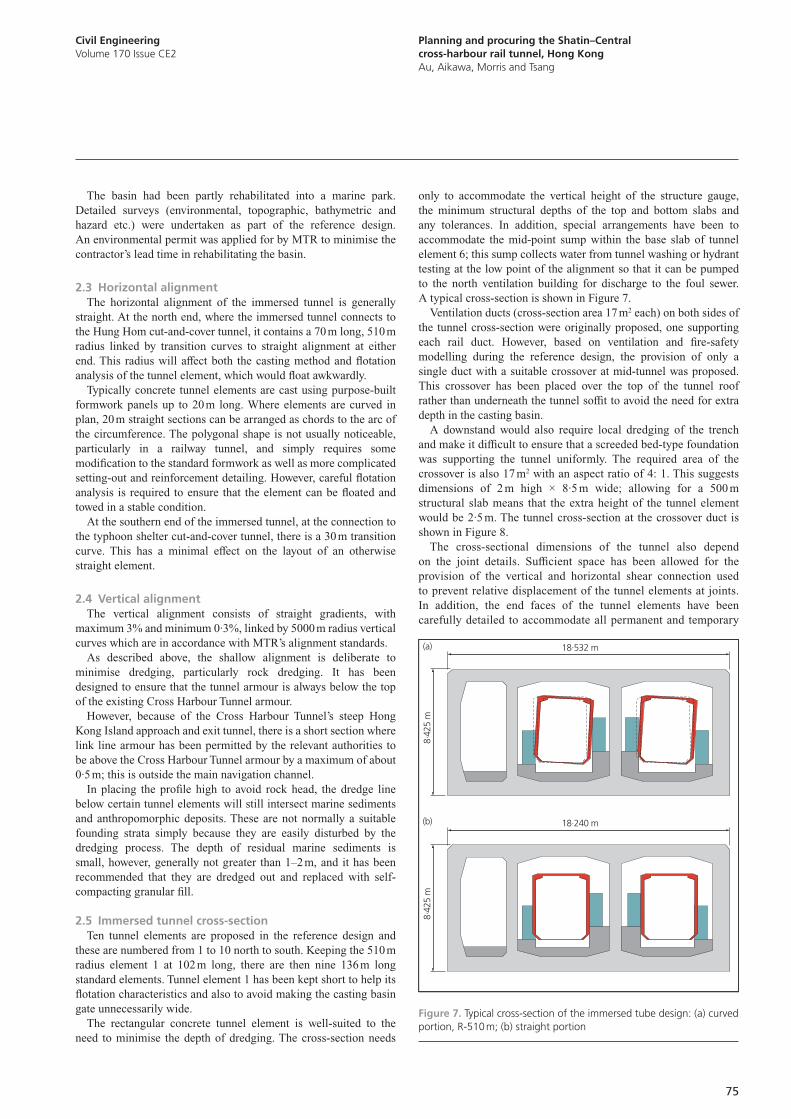
Planning and procuring the Shatin–Central cross-harbour rail tunnel, Hong KongAu, Aikawa, Morris and Tsang
Civil EngineeringVolume 170 Issue CE2
75
only to accommodate the vertical height of the structure gauge, the minimum structural depths of the top and bottom slabs and any tolerances. In addition, special arrangements have been to accommodate the mid-point sump within the base slab of tunnel element 6; this sump collects water from tunnel washing or hydrant testing at the low point of the alignment so that it can be pumped to the north ventilation building for discharge to the foul sewer. A typical cross-section is shown in Figure 7.
Ventilation ducts (cross-section area 17 m2 each) on both sides of the tunnel cross-section were originally proposed, one supporting each rail duct. However, based on ventilation and fire-safety modelling during the reference design, the provision of only a single duct with a suitable crossover at mid-tunnel was proposed. This crossover has been placed over the top of the tunnel roof rather than underneath the tunnel soffit to avoid the need for extra depth in the casting basin.
A downstand would also require local dredging of the trench and make it difficult to ensure that a screeded bed-type foundation was supporting the tunnel uniformly. The required area of the crossover is also 17 m2 with an aspect ratio of 4: 1. This suggests dimensions of 2 m high × 8·5 m wide; allowing for a 500 m structural slab means that the extra height of the tunnel element would be 2·5 m. The tunnel cross-section at the crossover duct is shown in Figure 8.
The cross-sectional dimensions of the tunnel also depend on the joint details. Sufficient space has been allowed for the provision of the vertical and horizontal shear connection used to prevent relative displacement of the tunnel elements at joints. In addition, the end faces of the tunnel elements have been carefully detailed to accommodate all permanent and temporary
The basin had been partly rehabilitated into a marine park. Detailed surveys (environmental, topographic, bathymetric and hazard etc.) were undertaken as part of the reference design. An environmental permit was applied for by MTR to minimise the contractor’s lead time in rehabilitating the basin.
2.3 Horizontal alignmentThe horizontal alignment of the immersed tunnel is generally
straight. At the north end, where the immersed tunnel connects to the Hung Hom cut-and-cover tunnel, it contains a 70 m long, 510 m radius linked by transition curves to straight alignment at either end. This radius will affect both the casting method and flotation analysis of the tunnel element, which would float awkwardly.
Typically concrete tunnel elements are cast using purpose-built formwork panels up to 20 m long. Where elements are curved in plan, 20 m straight sections can be arranged as chords to the arc of the circumference. The polygonal shape is not usually noticeable, particularly in a railway tunnel, and simply requires some modification to the standard formwork as well as more complicated setting-out and reinforcement detailing. However, careful flotation analysis is required to ensure that the element can be floated and towed in a stable condition.
At the southern end of the immersed tunnel, at the connection to the typhoon shelter cut-and-cover tunnel, there is a 30 m transition curve. This has a minimal effect on the layout of an otherwise straight element.
2.4 Vertical alignmentThe vertical alignment consists of straight gradients, with
maximum 3% and minimum 0·3%, linked by 5000 m radius vertical curves which are in accordance with MTR’s alignment standards.
As described above, the shallow alignment is deliberate to minimise dredging, particularly rock dredging. It has been designed to ensure that the tunnel armour is always below the top of the existing Cross Harbour Tunnel armour.
However, because of the Cross Harbour Tunnel’s steep Hong Kong Island approach and exit tunnel, there is a short section where link line armour has been permitted by the relevant authorities to be above the Cross Harbour Tunnel armour by a maximum of about 0·5 m; this is outside the main navigation channel.
In placing the profile high to avoid rock head, the dredge line below certain tunnel elements will still intersect marine sediments and anthropomorphic deposits. These are not normally a suitable founding strata simply because they are easily disturbed by the dredging process. The depth of residual marine sediments is small, however, generally not greater than 1–2 m, and it has been recommended that they are dredged out and replaced with self-compacting granular fill.
2.5 Immersed tunnel cross-sectionTen tunnel elements are proposed in the reference design and
these are numbered from 1 to 10 north to south. Keeping the 510 m radius element 1 at 102 m long, there are then nine 136 m long standard elements. Tunnel element 1 has been kept short to help its flotation characteristics and also to avoid making the casting basin gate unnecessarily wide.
The rectangular concrete tunnel element is well-suited to the need to minimise the depth of dredging. The cross-section needs
8.42
5 m
8.42
5 m
18.532 m (a)
(b) 18.240 m
Figure 7. Typical cross-section of the immersed tube design: (a) curved portion, R-510 m; (b) straight portion
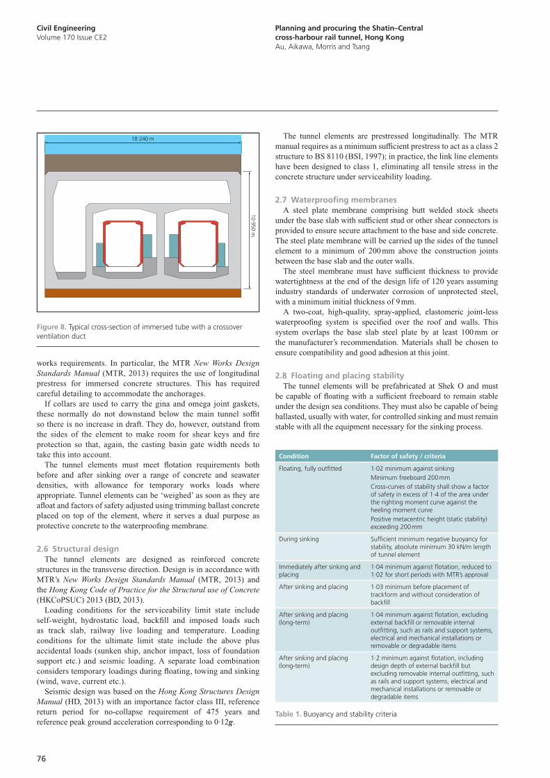
Civil EngineeringVolume 170 Issue CE2
Planning and procuring the Shatin–Central cross-harbour rail tunnel, Hong KongAu, Aikawa, Morris and Tsang
76
The tunnel elements are prestressed longitudinally. The MTR manual requires as a minimum sufficient prestress to act as a class 2 structure to BS 8110 (BSI, 1997); in practice, the link line elements have been designed to class 1, eliminating all tensile stress in the concrete structure under serviceability loading.
2.7 Waterproofing membranesA steel plate membrane comprising butt welded stock sheets
under the base slab with sufficient stud or other shear connectors is provided to ensure secure attachment to the base and side concrete. The steel plate membrane will be carried up the sides of the tunnel element to a minimum of 200 mm above the construction joints between the base slab and the outer walls.
The steel membrane must have sufficient thickness to provide watertightness at the end of the design life of 120 years assuming industry standards of underwater corrosion of unprotected steel, with a minimum initial thickness of 9 mm.
A two-coat, high-quality, spray-applied, elastomeric joint-less waterproofing system is specified over the roof and walls. This system overlaps the base slab steel plate by at least 100 mm or the manufacturer’s recommendation. Materials shall be chosen to ensure compatibility and good adhesion at this joint.
2.8 Floating and placing stabilityThe tunnel elements will be prefabricated at Shek O and must
be capable of floating with a sufficient freeboard to remain stable under the design sea conditions. They must also be capable of being ballasted, usually with water, for controlled sinking and must remain stable with all the equipment necessary for the sinking process.
works requirements. In particular, the MTR New Works Design Standards Manual (MTR, 2013) requires the use of longitudinal prestress for immersed concrete structures. This has required careful detailing to accommodate the anchorages.
If collars are used to carry the gina and omega joint gaskets, these normally do not downstand below the main tunnel soffit so there is no increase in draft. They do, however, outstand from the sides of the element to make room for shear keys and fire protection so that, again, the casting basin gate width needs to take this into account.
The tunnel elements must meet flotation requirements both before and after sinking over a range of concrete and seawater densities, with allowance for temporary works loads where appropriate. Tunnel elements can be ‘weighed’ as soon as they are afloat and factors of safety adjusted using trimming ballast concrete placed on top of the element, where it serves a dual purpose as protective concrete to the waterproofing membrane.
2.6 Structural designThe tunnel elements are designed as reinforced concrete
structures in the transverse direction. Design is in accordance with MTR’s New Works Design Standards Manual (MTR, 2013) and the Hong Kong Code of Practice for the Structural use of Concrete (HKCoPSUC) 2013 (BD, 2013).
Loading conditions for the serviceability limit state include self-weight, hydrostatic load, backfill and imposed loads such as track slab, railway live loading and temperature. Loading conditions for the ultimate limit state include the above plus accidental loads (sunken ship, anchor impact, loss of foundation support etc.) and seismic loading. A separate load combination considers temporary loadings during floating, towing and sinking (wind, wave, current etc.).
Seismic design was based on the Hong Kong Structures Design Manual (HD, 2013) with an importance factor class III, reference return period for no-collapse requirement of 475 years and reference peak ground acceleration corresponding to 0·12g.
Condition Factor of safety / criteria
Floating, fully outfitted 1·02 minimum against sinkingMinimum freeboard 200 mmCross-curves of stability shall show a factor of safety in excess of 1·4 of the area under the righting moment curve against the heeling moment curvePositive metacentric height (static stability) exceeding 200 mm
During sinking Sufficient minimum negative buoyancy for stability, absolute minimum 30 kN/m length of tunnel element
Immediately after sinking and placing
1·04 minimum against flotation, reduced to 1·02 for short periods with MTR’s approval
After sinking and placing 1·03 minimum before placement of trackform and without consideration of backfill
After sinking and placing (long-term)
1·04 minimum against flotation, excluding external backfill or removable internal outfitting, such as rails and support systems, electrical and mechanical installations or removable or degradable items
After sinking and placing (long-term)
1·2 minimum against flotation, including design depth of external backfill but excluding removable internal outfitting, such as rails and support systems, electrical and mechanical installations or removable or degradable items
Table 1. Buoyancy and stability criteria
10 .950 m
18.240 m
Figure 8. Typical cross-section of immersed tube with a crossover ventilation duct
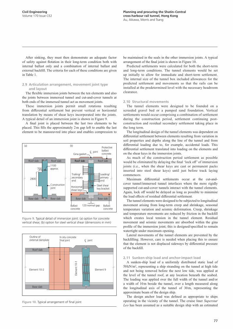
Planning and procuring the Shatin–Central cross-harbour rail tunnel, Hong KongAu, Aikawa, Morris and Tsang
Civil EngineeringVolume 170 Issue CE2
77
be maintained in the seals in the other immersion joints. A typical arrangement of the final joint is shown in Figure 10.
Predicted settlements were calculated for both the short-term and long-term conditions. The tunnel elements would be set up initially to allow for immediate and short-term settlement. The internal size of the tunnel box included allowances for the predicted settlement and movements so that the rails can be installed at the predetermined level with the necessary headroom clearance.
2.10 Structural movementsThe tunnel elements were designed to be founded on a
screeded gravel bed or a pumped sand foundation. Vertical settlements would occur comprising a combination of settlement during the construction period, settlement continuing post-construction and residual secondary settlement taking place in the long term.
The longitudinal design of the tunnel elements was dependent on differential settlement between elements resulting from variation in soil properties and depths along the line of the tunnel and from differential loading due to, for example, accidental loads. This differential settlement translated into loading on the elements and on the shear keys in the immersion joints.
As much of the construction period settlement as possible would be eliminated by delaying the final ‘lock off’ of immersion joints (i.e., when the shear keys are cast or permanent packs inserted into steel shear keys) until just before track laying commences.
Maximum differential settlements occur at the cut-and-cover tunnel/immersed tunnel interfaces where the more rigidly supported cut-and-cover tunnels interact with the tunnel elements. Again, lock off would be delayed as long as possible to minimise the load effects of residual differential settlement.
The tunnel elements were designed to be subjected to longitudinal movement arising from long-term creep and shrinkage, seasonal temperature variation and seismic deformation. Creep, shrinkage and temperature movements are reduced by friction in the backfill which creates local tension in the tunnel element. Residual movement and seismic movements are absorbed within the gina profile of the immersion joint; this is designed/specified to remain watertight under maximum opening.
Lateral movements of the tunnel elements are prevented by the backfilling. However, care is needed when placing this to ensure that the element is not displaced sideways by differential pressure of the backfill.
2.11 Sunken-ship load and anchor-impact loadA sunken-ship load of a uniformly distributed static load of
50 kN/m2, representing a ship stranding on the tunnel at high tide and not being removed before the next low tide, was applied at the level of the tunnel roof, at any location beneath the seabed. The loading was applied over the full width of the tunnel and/or a width of 10 m beside the tunnel, over a length measured along the longitudinal axis of the tunnel of 30 m, representing the approximate beam of the design ship.
The design anchor load was defined as appropriate to ships operating in the vicinity of the tunnel. The cruise liner Superstar Leo has been assumed as a suitable design ship with an estimated
After sinking, they must then demonstrate an adequate factor of safety against flotation in their long-term condition both with internal ballast only and a combination of internal ballast and external backfill. The criteria for each of these conditions are given in Table 1.
2.9 Articulation arrangement, movement joint type and layout
The flexible immersion joints between the ten elements and also the joints between immersed tunnel and cut-and-cover tunnels at both ends of the immersed tunnel act as movement joints.
These immersion joints permit small rotations resulting from differential settlement but prevent vertical or horizontal translation by means of shear keys incorporated into the joints. A typical detail of an immersion joint is shown in Figure 9.
A final joint is placed between the last two elements to be placed. This fills the approximately 2 m gap left to enable the last element to be manoeuvred into place and enables compression to
Constructionjoint
2800
(a) (b)
Base slab
Roof slab Roof slab Roof slab Roof slab
Base slab Base slab
Ballastconcrete
Ballastconcrete
120 normal gap
Protectiveballastconcrete
Base slab
7001100approx.
Trailing/secondaryend
Leading/primaryend
Steel shearkey bracket
Horizontalshear keys
Roof slab
Gina gasketC jointL
Figure 9. Typical detail of immersion joint: (a) option for concrete vertical shear, (b) option for steel vertical shear (dimensions in mm)
Base slab
Element 10-2
Elem
ent 1
0-1
Element 9
Roof slab
C jointL
In situ concretefinal joint
Outline of external damplate
Figure 10. Typical arrangement of final joint
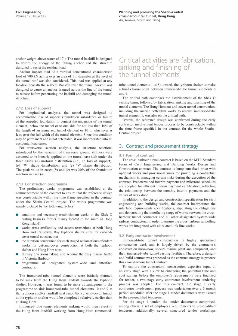
Civil EngineeringVolume 170 Issue CE2
Planning and procuring the Shatin–Central cross-harbour rail tunnel, Hong KongAu, Aikawa, Morris and Tsang
78
tube tunnel elements 1 to 8) towards the typhoon shelter to make a final closure joint between immersed-tube tunnel elements 8 and 9.
The critical path comprises the establishment of the Shek O casting basin, followed by fabrication, sinking and finishing of the tunnel elements. The Hung Hom cut-and-cover tunnel construction, including the marine cofferdam works to receive immersed-tube tunnel element 1, was also on the critical path.
Overall, the reference design was confirmed during the early contractor involvement tender process to be constructable within the time frame specified in the contract for the whole Shatin–Central project.
3. Contract and procurement strategy
3.1 Form of contractThe cross-harbour tunnel contract is based on the MTR Standard
Form of Civil Engineering and Building Works Design and Construction contract. The contract is lump-sum fixed price with optional works and provisional sums for providing a contractual mechanism in managing certain risks during the execution of the contract. Predetermined interim payment and milestone schedules are adopted for efficient interim payment certification, reflecting the relationship between the monthly interim payments and the values of work done.
In addition to the design and construction specification for civil engineering and building works, the contract incorporates the interface requirements specifications, stipulating the obligations and demarcating the interfacing scope of works between the cross-harbour tunnel contractor and all other designated system-wide railway contractors, in order to ensure the cross-harbour tunnelling works are integrated with all related link line works.
3.2 Early contractor involvementImmersed-tube tunnel construction is highly specialised
construction work and is largely driven by the contractor’s construction know-how, special marine plant and equipment, and their immersed-tube tunnel casting facilities. Therefore, a design-and-build contract was proposed as the contract strategy to procure this cross-harbour tunnel contract.
To capture the contractors’ construction expertise input at an early stage with a view to enhancing the potential time and cost savings before the employer’s requirements were finalised for tender, a two-stage early contractor involvement tendering process was adopted. For this contract, the stage 1 early contractor involvement process was undertaken over a 3 month period scheduled after the stage 1 tender documents were issued to the pre-qualified tenderers.
For the stage 1 tender, the tender documents comprised, among others, a set of employer’s requirements to pre-qualified tenderers; additionally, several structured tender workshops
anchor weight above water of 17 t. The tunnel backfill is designed to absorb the energy of the falling anchor and the structure designed to resist the residual load.
Anchor impact load of a vertical concentrated characteristic load of 700 kN acting over an area of 1 m diameter at the level of the tunnel roof was also considered. This load was applied at any location beneath the seabed. Rockfill over the tunnel backfill was designed to cause an anchor dragged across the line of the tunnel to release before penetrating the backfill and damaging the tunnel structure.
2.12 Loss of supportFor longitudinal analysis, the tunnel was designed to
accommodate loss of support (foundation subsidence or failure of the screeded foundation to contact the underside of the tunnel element) below the tunnel or to one side for not less than 10% of the length of an immersed tunnel element or 10 m, whichever is less, over the full width of the tunnel element. Since this condition may be permanent and is not detectable, it was incorporated into all accidental load cases.
For transverse section analysis, the structure reactions introduced by the variation of transverse ground stiffness were assumed to be linearly applied on the tunnel base slab under the three cases: (a) uniform distribution (i.e., no loss of support); (b) ‘W’ shape distribution; and (c) ‘V’ shape distribution. The peak value in cases (b) and (c) was 20% of the foundation reaction in case (a).
2.13 Construction programmeThe preliminary works programme was established at the
commencement of the contract to ensure that the reference design was constructable within the time frame specified in the contract under the Shatin–Central project. The works programme was mainly dictated by the following factors
■ condition and necessary establishment works at the Shek O casting basin (a former quarry located to the south of Hong Kong Island)
■ works areas availability and access restrictions at both Hung Hom and Causeway Bay typhoon shelter sites for cut-and-cover tunnel construction
■ the duration constrained for each staged reclamation/cofferdam works for cut-and-cover construction at both the typhoon shelter and Hung Hom sites
■ fairway diversions taking into account the busy marine traffic in Victoria Harbour
■ programme of designated system-wide and interface contracts.
The immersed-tube tunnel elements were initially planned to be sunk from the Hung Hom landfall towards the typhoon shelter. However, it was found to be more advantageous to the programme to sink immersed-tube tunnel elements 10 and 9 at the typhoon shelter landfall first since the cut-and-cover tunnel at the typhoon shelter would be completed relatively earlier than at Hung Hom.
Immersed-tube tunnel elements sinking would then revert to the Hung Hom landfall working from Hung Hom (immersed-
Critical activities are fabrication, sinking and finishing of the tunnel elements
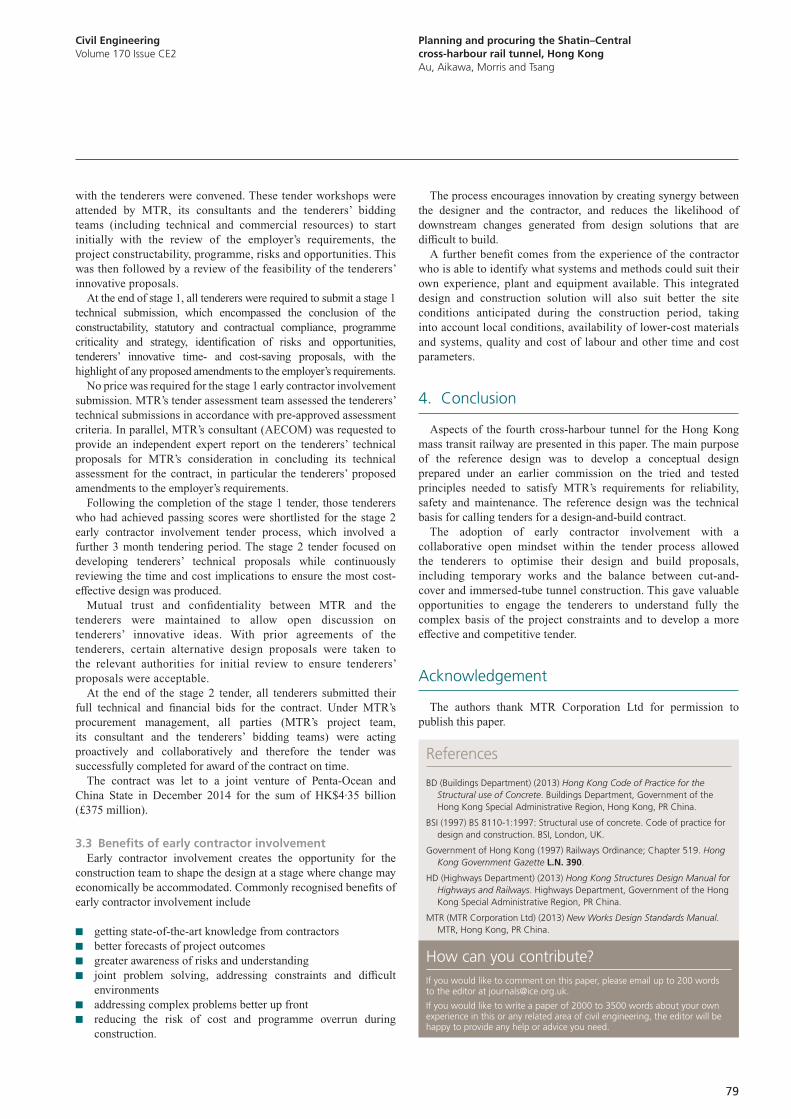
Planning and procuring the Shatin–Central cross-harbour rail tunnel, Hong KongAu, Aikawa, Morris and Tsang
Civil EngineeringVolume 170 Issue CE2
79
The process encourages innovation by creating synergy between the designer and the contractor, and reduces the likelihood of downstream changes generated from design solutions that are difficult to build.
A further benefit comes from the experience of the contractor who is able to identify what systems and methods could suit their own experience, plant and equipment available. This integrated design and construction solution will also suit better the site conditions anticipated during the construction period, taking into account local conditions, availability of lower-cost materials and systems, quality and cost of labour and other time and cost parameters.
4. Conclusion
Aspects of the fourth cross-harbour tunnel for the Hong Kong mass transit railway are presented in this paper. The main purpose of the reference design was to develop a conceptual design prepared under an earlier commission on the tried and tested principles needed to satisfy MTR’s requirements for reliability, safety and maintenance. The reference design was the technical basis for calling tenders for a design-and-build contract.
The adoption of early contractor involvement with a collaborative open mindset within the tender process allowed the tenderers to optimise their design and build proposals, including temporary works and the balance between cut-and-cover and immersed-tube tunnel construction. This gave valuable opportunities to engage the tenderers to understand fully the complex basis of the project constraints and to develop a more effective and competitive tender.
Acknowledgement
The authors thank MTR Corporation Ltd for permission to publish this paper.
with the tenderers were convened. These tender workshops were attended by MTR, its consultants and the tenderers’ bidding teams (including technical and commercial resources) to start initially with the review of the employer’s requirements, the project constructability, programme, risks and opportunities. This was then followed by a review of the feasibility of the tenderers’ innovative proposals.
At the end of stage 1, all tenderers were required to submit a stage 1 technical submission, which encompassed the conclusion of the constructability, statutory and contractual compliance, programme criticality and strategy, identification of risks and opportunities, tenderers’ innovative time- and cost-saving proposals, with the highlight of any proposed amendments to the employer’s requirements.
No price was required for the stage 1 early contractor involvement submission. MTR’s tender assessment team assessed the tenderers’ technical submissions in accordance with pre-approved assessment criteria. In parallel, MTR’s consultant (AECOM) was requested to provide an independent expert report on the tenderers’ technical proposals for MTR’s consideration in concluding its technical assessment for the contract, in particular the tenderers’ proposed amendments to the employer’s requirements.
Following the completion of the stage 1 tender, those tenderers who had achieved passing scores were shortlisted for the stage 2 early contractor involvement tender process, which involved a further 3 month tendering period. The stage 2 tender focused on developing tenderers’ technical proposals while continuously reviewing the time and cost implications to ensure the most cost-effective design was produced.
Mutual trust and confidentiality between MTR and the tenderers were maintained to allow open discussion on tenderers’ innovative ideas. With prior agreements of the tenderers, certain alternative design proposals were taken to the relevant authorities for initial review to ensure tenderers’ proposals were acceptable.
At the end of the stage 2 tender, all tenderers submitted their full technical and financial bids for the contract. Under MTR’s procurement management, all parties (MTR’s project team, its consultant and the tenderers’ bidding teams) were acting proactively and collaboratively and therefore the tender was successfully completed for award of the contract on time.
The contract was let to a joint venture of Penta-Ocean and China State in December 2014 for the sum of HK$4·35 billion (£375 million).
3.3 Benefits of early contractor involvementEarly contractor involvement creates the opportunity for the
construction team to shape the design at a stage where change may economically be accommodated. Commonly recognised benefits of early contractor involvement include
■ getting state-of-the-art knowledge from contractors ■ better forecasts of project outcomes ■ greater awareness of risks and understanding ■ joint problem solving, addressing constraints and difficult
environments ■ addressing complex problems better up front ■ reducing the risk of cost and programme overrun during
construction.
References
BD (Buildings Department) (2013) Hong Kong Code of Practice for the Structural use of Concrete. Buildings Department, Government of the Hong Kong Special Administrative Region, Hong Kong, PR China.
BSI (1997) BS 8110-1:1997: Structural use of concrete. Code of practice for design and construction. BSI, London, UK.
Government of Hong Kong (1997) Railways Ordinance; Chapter 519. Hong Kong Government Gazette L.N. 390.
HD (Highways Department) (2013) Hong Kong Structures Design Manual for Highways and Railways. Highways Department, Government of the Hong Kong Special Administrative Region, PR China.
MTR (MTR Corporation Ltd) (2013) New Works Design Standards Manual. MTR, Hong Kong, PR China.
How can you contribute?If you would like to comment on this paper, please email up to 200 words to the editor at [email protected].
If you would like to write a paper of 2000 to 3500 words about your own experience in this or any related area of civil engineering, the editor will be happy to provide any help or advice you need.

In 2017, the Institution of Civil Engineers is launching a new journal, Smart Infrastructure and Construction, as part of its Proceedings series.
Smart Infrastructure and Construction will provide a learned forum for documenting changes caused by the global adoption of emerging digital technology in the design, construction and management of infrastructure assets. These radical changes will lead to greater efficiency, economy, adaptability and sustainability in the way our infrastructure is delivered and operated.
Working in collaboration with the Cambridge Centre for Smart Infrastructure and Construction (CCSIC), the journal will publish original research papers, briefings, discussions and reviews. Smart Infrastructure and Construction will appear quarterly in a digital-only format and will provide free access to its content throughout 2017 and 2018 to allow for the widest dissemination of its findings.
Contributions to the inaugural issues of the journal are welcome. Suggested topics include, but are not limited to:
■ adaptive structure design and construction
■ additive layer manufacturing in construction
■ automated infrastructure construction systems
■ citizens as sensors
■ city-scale infrastructure planning and operations
■ city-scale simulations and data analytics
■ deterioration modelling
■ digital engineering and BIM
■ infrastructure resilience
■ offsite manufacture and innovative manufacturing methods
■ performance-based design and maintenance
■ sensing solutions for infrastructure monitoring
■ smart cities
■ smart construction technology
■ value of sensing
■ whole-life cost and value
Smart Infrastructure and ConstructionCo-Editors: Dr Jennifer Schooling, Centre for Smart Infrastructure and Construction, University of Cambridge, UK Prof Kenichi Soga, Dept of Civil and Environmental Engineering, University of California - Berkeley, USA
Call for Papers
Why Publish with ICE?
ICE Publishing has been uniting research and practice in engineering and science since 1836. As the publishing arm of the Institution of Civil Engineers, we provide exclusive access to over 80,000 active ICE members in 160 countries.
By publishing with ICE, you will benefit from our quality, visibility and advocacy.
QUALITY
• Rigorous blind peer review by an international panel of experts
• Author editorial support and guidance to help you develop your work
• Professional copy editing, typesetting and proof-reading services
• No publication charges, it is entirely free to publish with us (Open Access titles excepted)
VISIBILITY
• Our journals are included in major science and engineering databases and indexes making our articles easily discoverable in Google and other scholarly search engines
• In addition to ICE members, our content is read by academics and practitioners at over 1500 subscribing universities, corporations, and government agencies around the world
ADVOCACY
• We work closely with our authors and editors to promote our journals to all relevant audiences, at international conferences, and through engineering social networks
Invitation to Authors
To submit an abstract or to request further information, please contact:
Sam Hall, Journals Development Editor
T: +44 (0)20 7665 2450 E: [email protected]
Proceedings of the Institution of Civil Engineers
81
In meteorology, weather forecasting uses thermal images from satellites.
Thermal imaging cameras are also often used by law enforcement helicopters at night during rescue operations or when tracking fugitives.
The potential use of thermal imaging in civil engineering is less well established or known. This paper presents a field study where thermal imaging technology is used as a tool for civil engineering application. Although the thermal imaging process is not new, in recent years the technology has greatly improved to the extent that temperature data can now be shown for each image pixel, and graphs can be created showing temperature change over an area.
Furthermore, thermal imaging has become more accessible and less costly compared to what was available a few years ago. Thermal imaging is now possible with small hand-held devices such as the Landguide M4 or Flir C2, as a smartphone attachment like Flir One, or as an in-built small phone such as Cat S60. The thermal images presented in this paper were obtained using a Landguide M4, which is one of the smallest and lightest devices of its kind in use today.
2. Background to thermal imaging
Thermal imagers detect radiation in the infrared range (Figure 1) of the electromagnetic spectrum – that is, waves of approximately 700 nm to 1 mm wavelengths. The basis for infrared imaging technology is that any object, whose temperature is above 0 K,
1. Introduction
Thermal imaging originated for military use and remained relatively restricted for several decades. It provided military personnel with the ability to view opposing forces during darkness or in smoke-covered battlegrounds. Over the last decade, the use of thermal imaging technology has propagated into several fields and its effectiveness has led to many successful new applications – including in civil engineering.
The properties that have made thermal imaging detection valuable to military forces around the world also make it valuable in many other disciplines, including medicine, emergency and rescue services, electrical and building engineering, meteorology and law enforcement.
In the medical field, thermal images are being used to assess inflammation in the arteries; to identify and screen travellers with high fever in airports; to diagnose a variety of disorders associated with the neck, back and limbs; and for early detection of breast cancer.
In emergency and rescue applications, firefighters use thermography to see through smoke, to locate injured persons and to locate the base of a fire, while rescue personnel use the technology to locate trapped persons following an earthquake or building collapse.
In electrical engineering, maintenance engineers use thermography to locate and help repair any overheating joints on power lines.
Building engineers use thermal imaging to identify any areas of faulty thermal insulation and use the results to improve the efficiency of heating and air-conditioning systems.
Innovative uses of thermal imaging in civil engineering1 Indrasenan Thusyanthan CEng, PhD, CMarEng, MICE, BA,
MEngGeotechnical Consultant, Thusyanthan Consultants Ltd., London, UK (corresponding author: [email protected])
2 Tim Blower CEng, FICE, BSc, MSc, DIC, CGeol, FGS, SiLCTechnical Director, Mott MacDonald, Cambridge, UK
3 William Cleverly CEng, MEng, MICE, MAGeotechnical Engineering Manager, Offshore Wind Consultants Ltd, London, UK
Thermal imaging captures information in the infrared spectrum of light invisible to people, thus it can
provide valuable extra information. Innovative use of thermal imaging technology can therefore play an
important role in many civil engineering applications. This paper provides insight into thermal imaging
technology and its uses in civil engineering. A field example of early leak detection in an earth embankment
using thermal imaging technology is presented. With ever-improving thermal imaging technology and
decreasing cost of thermal imaging cameras, many future uses of thermal imaging in civil engineering are
envisaged – from pipeline leak detection to structural integrity inspections, energy efficiency surveys and
pollution monitoring. The small size of the equipment means it can also be carried by drones, offering
access to remote or otherwise inaccessible areas.
Proceedings of the Institution of Civil EngineersCivil Engineering 170 May 2017 Issue CE2Pages 81–87 http://dx.doi.org/10.1680/jcien.16.00014Paper 1600014Received 22/04/2016 Accepted 26/09/2016Published online 21/11/2016Keywords: embankments/geotechnical engineering/pipes & pipelines
Civil EngineeringVolume 170 Issue CE2
Innovative uses of thermal imaging in civil engineeringThusyanthan, Blower and Cleverly
ICE Publishing: All rights reserved
1 2 3
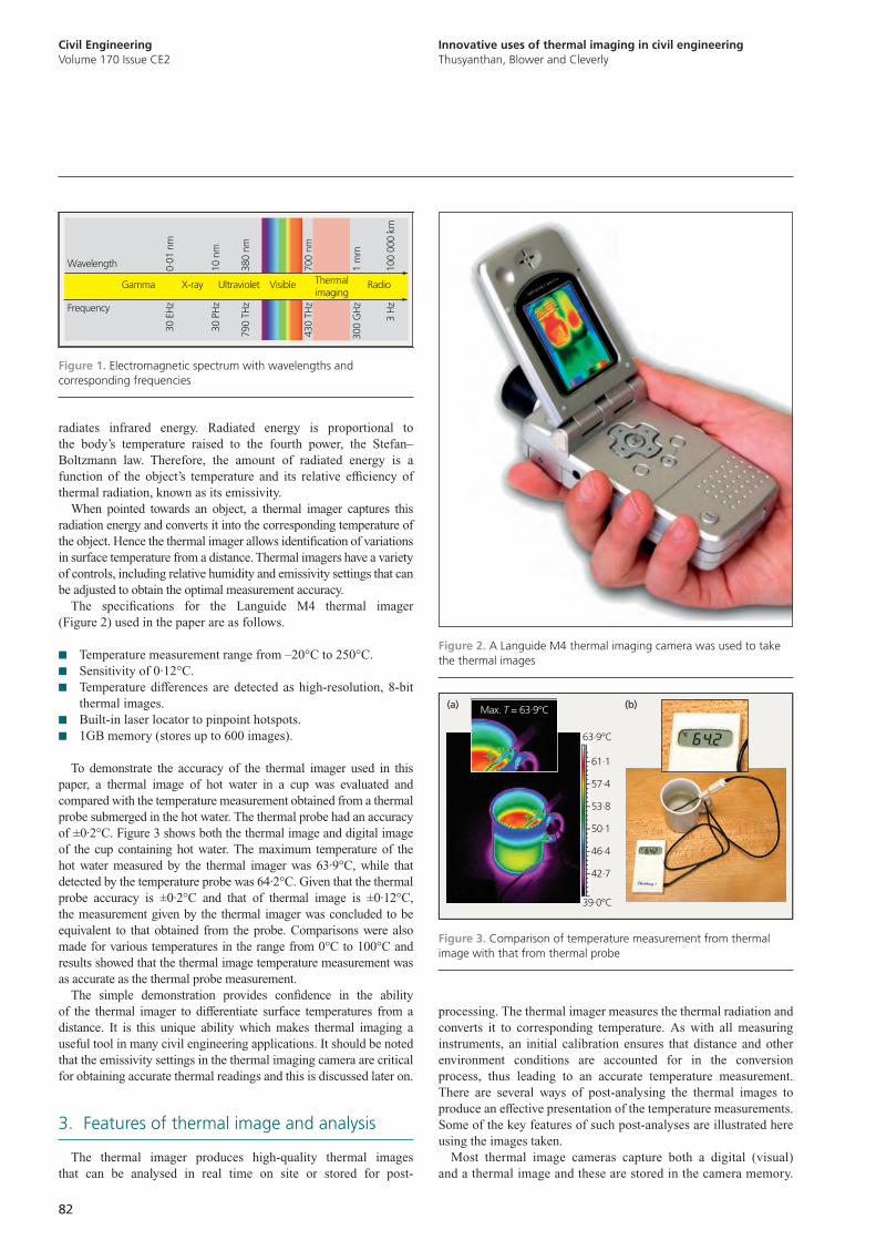
Civil EngineeringVolume 170 Issue CE2
Innovative uses of thermal imaging in civil engineeringThusyanthan, Blower and Cleverly
82
processing. The thermal imager measures the thermal radiation and converts it to corresponding temperature. As with all measuring instruments, an initial calibration ensures that distance and other environment conditions are accounted for in the conversion process, thus leading to an accurate temperature measurement. There are several ways of post-analysing the thermal images to produce an effective presentation of the temperature measurements. Some of the key features of such post-analyses are illustrated here using the images taken.
Most thermal image cameras capture both a digital (visual) and a thermal image and these are stored in the camera memory.
radiates infrared energy. Radiated energy is proportional to the body’s temperature raised to the fourth power, the Stefan–Boltzmann law. Therefore, the amount of radiated energy is a function of the object’s temperature and its relative efficiency of thermal radiation, known as its emissivity.
When pointed towards an object, a thermal imager captures this radiation energy and converts it into the corresponding temperature of the object. Hence the thermal imager allows identification of variations in surface temperature from a distance. Thermal imagers have a variety of controls, including relative humidity and emissivity settings that can be adjusted to obtain the optimal measurement accuracy.
The specifications for the Languide M4 thermal imager (Figure 2) used in the paper are as follows.
■ Temperature measurement range from –20°C to 250°C. ■ Sensitivity of 0·12°C. ■ Temperature differences are detected as high-resolution, 8-bit
thermal images. ■ Built-in laser locator to pinpoint hotspots. ■ 1GB memory (stores up to 600 images).
To demonstrate the accuracy of the thermal imager used in this paper, a thermal image of hot water in a cup was evaluated and compared with the temperature measurement obtained from a thermal probe submerged in the hot water. The thermal probe had an accuracy of ±0·2°C. Figure 3 shows both the thermal image and digital image of the cup containing hot water. The maximum temperature of the hot water measured by the thermal imager was 63·9°C, while that detected by the temperature probe was 64·2°C. Given that the thermal probe accuracy is ±0·2°C and that of thermal image is ±0·12°C, the measurement given by the thermal imager was concluded to be equivalent to that obtained from the probe. Comparisons were also made for various temperatures in the range from 0°C to 100°C and results showed that the thermal image temperature measurement was as accurate as the thermal probe measurement.
The simple demonstration provides confidence in the ability of the thermal imager to differentiate surface temperatures from a distance. It is this unique ability which makes thermal imaging a useful tool in many civil engineering applications. It should be noted that the emissivity settings in the thermal imaging camera are critical for obtaining accurate thermal readings and this is discussed later on.
3. Features of thermal image and analysis
The thermal imager produces high-quality thermal images that can be analysed in real time on site or stored for post-
Wavelength
30 E
Hz
Gamma X-ray Ultraviolet Visible Thermalimaging
Radio
Frequency
16_00014fig01Barking Dog Art
0.01
nm
30 P
Hz
10 n
m
790
THz
380
nm
430
THz
700
nm
300
GH
z1
mm
3 H
z10
0 00
0 km
Figure 1. Electromagnetic spectrum with wavelengths and corresponding frequencies
Figure 2. A Languide M4 thermal imaging camera was used to take the thermal images
61·1
57·4
53·8
50·1
46·4
42·7
63·9°C
Max. T = 63.9°C
39·0°C
(a) (b)
Figure 3. Comparison of temperature measurement from thermal image with that from thermal probe
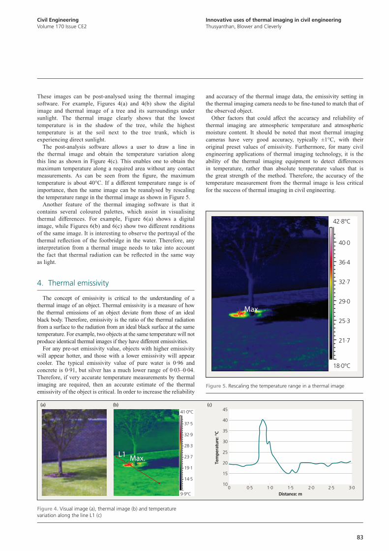
Innovative uses of thermal imaging in civil engineeringThusyanthan, Blower and Cleverly
Civil EngineeringVolume 170 Issue CE2
83
and accuracy of the thermal image data, the emissivity setting in the thermal imaging camera needs to be fine-tuned to match that of the observed object.
Other factors that could affect the accuracy and reliability of thermal imaging are atmospheric temperature and atmospheric moisture content. It should be noted that most thermal imaging cameras have very good accuracy, typically ±1°C, with their original preset values of emissivity. Furthermore, for many civil engineering applications of thermal imaging technology, it is the ability of the thermal imaging equipment to detect differences in temperature, rather than absolute temperature values that is the great strength of the method. Therefore, the accuracy of the temperature measurement from the thermal image is less critical for the success of thermal imaging in civil engineering.
These images can be post-analysed using the thermal imaging software. For example, Figures 4(a) and 4(b) show the digital image and thermal image of a tree and its surroundings under sunlight. The thermal image clearly shows that the lowest temperature is in the shadow of the tree, while the highest temperature is at the soil next to the tree trunk, which is experiencing direct sunlight.
The post-analysis software allows a user to draw a line in the thermal image and obtain the temperature variation along this line as shown in Figure 4(c). This enables one to obtain the maximum temperature along a required area without any contact measurements. As can be seen from the figure, the maximum temperature is about 40°C. If a different temperature range is of importance, then the same image can be reanalysed by rescaling the temperature range in the thermal image as shown in Figure 5.
Another feature of the thermal imaging software is that it contains several coloured palettes, which assist in visualising thermal differences. For example, Figure 6(a) shows a digital image, while Figures 6(b) and 6(c) show two different renditions of the same image. It is interesting to observe the portrayal of the thermal reflection of the footbridge in the water. Therefore, any interpretation from a thermal image needs to take into account the fact that thermal radiation can be reflected in the same way as light.
4. Thermal emissivity
The concept of emissivity is critical to the understanding of a thermal image of an object. Thermal emissivity is a measure of how the thermal emissions of an object deviate from those of an ideal black body. Therefore, emissivity is the ratio of the thermal radiation from a surface to the radiation from an ideal black surface at the same temperature. For example, two objects at the same temperature will not produce identical thermal images if they have different emissivities.
For any pre-set emissivity value, objects with higher emissivity will appear hotter, and those with a lower emissivity will appear cooler. The typical emissivity value of pure water is 0·96 and concrete is 0·91, but silver has a much lower range of 0·03–0·04. Therefore, if very accurate temperature measurements by thermal imaging are required, then an accurate estimate of the thermal emissivity of the object is critical. In order to increase the reliability
45
40
35
30
25
20
15
10
Tem
pera
ture
: °C
Distance: m0.5 1.0 1.5 2.0 2.5 3.00
37.5
32.9
28.3
23.7
19.1
14.5
41.0°C
9.9°C
(a) (b) (c)
Max.L1
Figure 4. Visual image (a), thermal image (b) and temperature variation along the line L1 (c)
40·0
36·4
32·7
29·0
25·3
21·7
42·8°C
18·0°C
Max.
Figure 5. Rescaling the temperature range in a thermal image
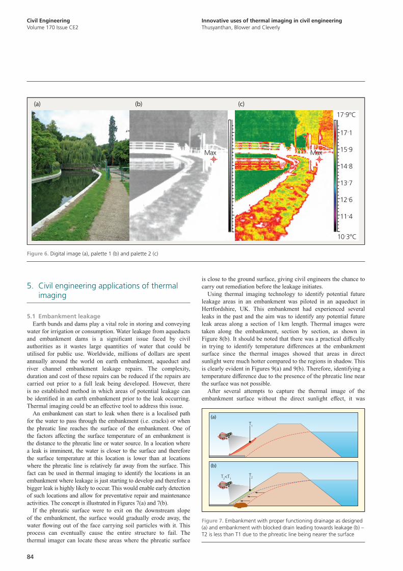
Civil EngineeringVolume 170 Issue CE2
Innovative uses of thermal imaging in civil engineeringThusyanthan, Blower and Cleverly
84
is close to the ground surface, giving civil engineers the chance to carry out remediation before the leakage initiates.
Using thermal imaging technology to identify potential future leakage areas in an embankment was piloted in an aqueduct in Hertfordshire, UK. This embankment had experienced several leaks in the past and the aim was to identify any potential future leak areas along a section of 1 km length. Thermal images were taken along the embankment, section by section, as shown in Figure 8(b). It should be noted that there was a practical difficulty in trying to identify temperature differences at the embankment surface since the thermal images showed that areas in direct sunlight were much hotter compared to the regions in shadow. This is clearly evident in Figures 9(a) and 9(b). Therefore, identifying a temperature difference due to the presence of the phreatic line near the surface was not possible.
After several attempts to capture the thermal image of the embankment surface without the direct sunlight effect, it was
5. Civil engineering applications of thermal imaging
5.1 Embankment leakageEarth bunds and dams play a vital role in storing and conveying
water for irrigation or consumption. Water leakage from aqueducts and embankment dams is a significant issue faced by civil authorities as it wastes large quantities of water that could be utilised for public use. Worldwide, millions of dollars are spent annually around the world on earth embankment, aqueduct and river channel embankment leakage repairs. The complexity, duration and cost of these repairs can be reduced if the repairs are carried out prior to a full leak being developed. However, there is no established method in which areas of potential leakage can be identified in an earth embankment prior to the leak occurring. Thermal imaging could be an effective tool to address this issue.
An embankment can start to leak when there is a localised path for the water to pass through the embankment (i.e. cracks) or when the phreatic line reaches the surface of the embankment. One of the factors affecting the surface temperature of an embankment is the distance to the phreatic line or water source. In a location where a leak is imminent, the water is closer to the surface and therefore the surface temperature at this location is lower than at locations where the phreatic line is relatively far away from the surface. This fact can be used in thermal imaging to identify the locations in an embankment where leakage is just starting to develop and therefore a bigger leak is highly likely to occur. This would enable early detection of such locations and allow for preventative repair and maintenance activities. The concept is illustrated in Figures 7(a) and 7(b).
If the phreatic surface were to exit on the downstream slope of the embankment, the surface would gradually erode away, the water flowing out of the face carrying soil particles with it. This process can eventually cause the entire structure to fail. The thermal imager can locate these areas where the phreatic surface
(a)
(b)
T1
T2<T1T2
Figure 7. Embankment with proper functioning drainage as designed (a) and embankment with blocked drain leading towards leakage (b) – T2 is less than T1 due to the phreatic line being nearer the surface
17.1
15.9
14.8
13.7
12.6
11.4
17.9°C
10.3°C
MaxMax
(a) (b) (c)
Figure 6. Digital image (a), palette 1 (b) and palette 2 (c)
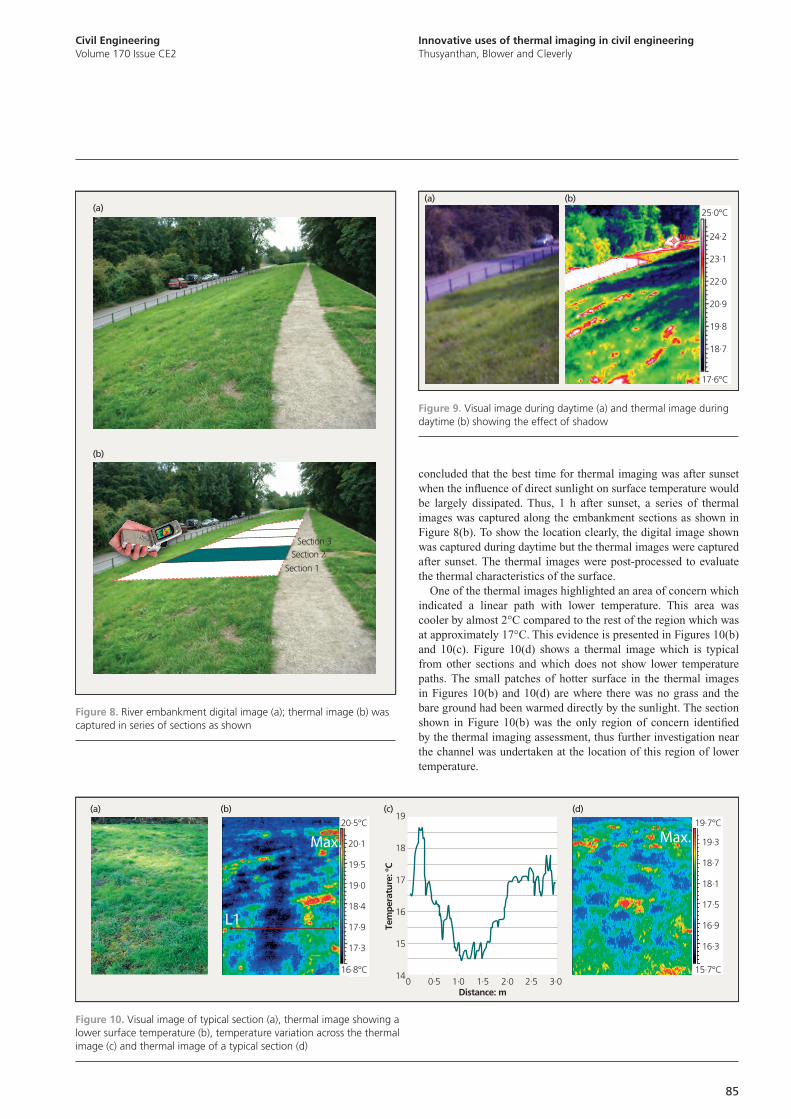
Innovative uses of thermal imaging in civil engineeringThusyanthan, Blower and Cleverly
Civil EngineeringVolume 170 Issue CE2
85
concluded that the best time for thermal imaging was after sunset when the influence of direct sunlight on surface temperature would be largely dissipated. Thus, 1 h after sunset, a series of thermal images was captured along the embankment sections as shown in Figure 8(b). To show the location clearly, the digital image shown was captured during daytime but the thermal images were captured after sunset. The thermal images were post-processed to evaluate the thermal characteristics of the surface.
One of the thermal images highlighted an area of concern which indicated a linear path with lower temperature. This area was cooler by almost 2°C compared to the rest of the region which was at approximately 17°C. This evidence is presented in Figures 10(b) and 10(c). Figure 10(d) shows a thermal image which is typical from other sections and which does not show lower temperature paths. The small patches of hotter surface in the thermal images in Figures 10(b) and 10(d) are where there was no grass and the bare ground had been warmed directly by the sunlight. The section shown in Figure 10(b) was the only region of concern identified by the thermal imaging assessment, thus further investigation near the channel was undertaken at the location of this region of lower temperature.
(a)
(b)
Section 1
Section 2Section 3
Figure 8. River embankment digital image (a); thermal image (b) was captured in series of sections as shown
24.2
23.1
22.0
20.9
19.8
18.7
25.0°C
17.6°C
(a) (b)
Figure 9. Visual image during daytime (a) and thermal image during daytime (b) showing the effect of shadow
(a) (b) (c) (d)
L1
Max. Max.19
18
17
16
15
14
Tem
pera
ture
: °C
Distance: m0.50 1.0 1.5 2.0 2.5 3.0
20.1
19.5
19.0
18.4
17.9
17.3
16.8°C
19·3
18·7
18·1
17·5
16·9
16·3
19·7°C
15·7°C
20.5°C
Figure 10. Visual image of typical section (a), thermal image showing a lower surface temperature (b), temperature variation across the thermal image (c) and thermal image of a typical section (d)
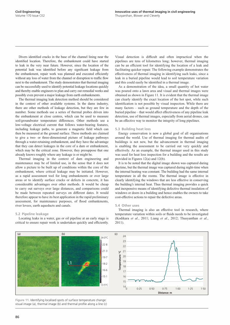
Civil EngineeringVolume 170 Issue CE2
Innovative uses of thermal imaging in civil engineeringThusyanthan, Blower and Cleverly
86
Visual detection is difficult and often impractical when the pipelines are tens of kilometres long; however, thermal imaging can be an efficient tool for identifying the location of a leak and facilitating quicker repair. The following example demonstrates the effectiveness of thermal imaging in identifying such leaks, since a leak in a buried pipeline would lead to soil temperature variation and this could easily be identified in a thermal image.
As a demonstration of the idea, a small quantity of hot water was poured onto a lawn area and visual and thermal images were obtained as shown in Figure 11. It is evident that the thermal image can clearly identify the exact location of the hot spot, while such identification is not possible by visual inspection. While there are many factors – such as ground temperature and the depth of the buried pipeline – that would affect effectiveness of any pipeline leak detection, use of thermal images, especially from aerial drones, can be an effective way to monitor the integrity of long pipelines.
5.3 Building heat lossEnergy conservation is now a global goal of all organisations
around the world. Use of thermal imaging for thermal audits of buildings is not new, but the advancement in thermal imaging is enabling the assessment to be carried out very quickly and effectively. As an example, the thermal imager used in this study was used for heat loss inspection for a building and the results are provided in Figures 12(a) and 12(b).
It is to be noted that the digital image shown was captured during daytime, but the thermal image was captured during night-time when the internal heating was constant. The building had the same internal temperature in all the rooms. The thermal image is effective in clearly identifying the windows that are less effective in conserving the building’s internal heat. Thus thermal imaging provides a quick and inexpensive means of identifying defective thermal insulation of windows or doors in a building and hence enables the owners to take cost-effective actions to repair the defective areas.
5.4 Other usesThermal imaging is also an effective tool in research, where
temperature variation within soils or fluids needs to be investigated (Kodikara et al., 2011; Liang et al., 2012; Thusyanthan et al., 2011).
Divers identified cracks in the base of the channel lining near the identified location. Therefore, the embankment could have started to leak in the very near future. However, since the location of the potential leak was identified before any significant leakage from the embankment, repair work was planned and executed efficiently without any loss of water from the channel or disruption to traffic flow next to the embankment. The study demonstrates that thermal imaging can be successfully used to identify potential leakage locations quickly and thereby enable engineers to plan and carry out remedial works and possibly even prevent a major leakage from earth embankments.
The thermal imaging leak detection method should be considered in the context of other available systems. In the dams industry, there are other methods of leakage detection, but they are few in number. Some methods use a series of thermal probes driven into the embankment at close centres, which can be used to measure soil/groundwater temperature differences. Other methods use a low-voltage electrical current that follows water-bearing features, including leakage paths, to generate a magnetic field which can then be measured at the ground surface. These methods are claimed to give a two- or three-dimensional picture of leakage pathways through a water-retaining embankment, and they have the advantage that they can detect leakages in the core of a dam or embankment, which may be the critical zone. However, they presuppose that one already knows roughly where any leakage is or might be.
Thermal imaging in the context of dam engineering and maintenance may be of limited use, in the sense that it does not allow a picture to be built up of conditions within the core of the embankment, where critical leakage may be initiated. However, as a rapid assessment tool for long embankments or over large areas or to identify surface cracks or defects in concrete, it has considerable advantages over other methods. It would be cheap to carry out surveys over large distances, and comparisons could be made between repeated surveys on different dates. It would therefore appear to have its best application in the rapid preliminary assessment, for maintenance purposes, of flood embankments, river levees, earth aqueducts and canals.
5.2 Pipeline leakageLocating leaks in a water, gas or oil pipeline at an early stage is
critical to ensure repair work is undertaken quickly and efficiently.
22.8
21.3
19.7
18.2
16.6
15.1
24.0°C
13.5°C0.250 0.50 0.75 1.00 1.25 1.50
24
23
22
21
20
19
18
17
16
15
14
Tem
pera
ture
: °C
Distance: m
L1
(a) (b) (c)
Figure 11. Identifying localised spots of surface temperature change: visual image (a), thermal image (b) and thermal profile along a line (c)
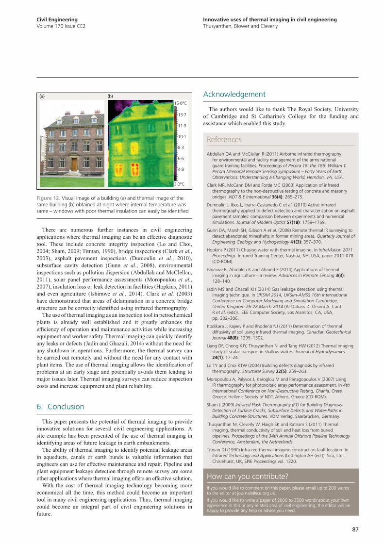
Innovative uses of thermal imaging in civil engineeringThusyanthan, Blower and Cleverly
Civil EngineeringVolume 170 Issue CE2
87
References
Abdullah QA and McClellan R (2011) Airborne infrared thermography for environmental and facility management of the army national guard training facilities. Proceedings of Pecora 18: the 18th William T. Pecora Memorial Remote Sensing Symposium – Forty Years of Earth Observations: Understanding a Changing World, Herndon, VA, USA.
Clark MR, McCann DM and Forde MC (2003) Application of infrared thermography to the non-destructive testing of concrete and masonry bridges. NDT & E International 36(4): 265–275.
Dumoulin J, Ibos L, Ibarra-Castanedo C et al. (2010) Active infrared thermography applied to defect detection and characterization on asphalt pavement samples: comparison between experiments and numerical simulations. Journal of Modern Optics 57(18): 1759–1769.
Gunn DA, Marsh SH, Gibson A et al. (2008) Remote thermal IR surveying to detect abandoned mineshafts in former mining areas. Quarterly Journal of Engineering Geology and Hydrogeology 41(3): 357–370.
Hopkins P (2011) Chasing water with thermal imaging. In InfraMation 2011 Proceedings. Infrared Training Center, Nashua, NH, USA, paper 2011-078 (CD-ROM).
Ishimwe R, Abutaleb K and Ahmed F (2014) Applications of thermal imaging in agriculture – a review. Advances in Remote Sensing 3(3): 128–140.
Jadin MS and Ghazali KH (2014) Gas leakage detection using thermal imaging technique. In UKSIM 2014, UKSim-AMSS 16th International Conference on Computer Modelling and Simulation Cambridge, United Kingdom 26-28 March 2014 (Al-Dabass D, Orsoni A, Cant R et al. (eds)). IEEE Computer Society, Los Alamitos, CA, USA, pp. 302–306.
Kodikara J, Rajeev P and Rhodenb NJ (2011) Determination of thermal diffusivity of soil using infrared thermal imaging. Canadian Geotechnical Journal 48(8): 1295–1302.
Liang DF, Chong KJY, Thusyanthan NI and Tang HW (2012) Thermal imaging study of scalar transport in shallow wakes. Journal of Hydrodynamics 24(1): 17–24.
Lo TY and Choi KTW (2004) Building defects diagnosis by infrared thermography. Structural Survey 22(5): 259–263.
Moropoulou A, Palyvos J, Karoglou M and Panagopoulos V (2007) Using IR thermography for photovoltaic array performance assessment. In 4th International Conference on Non-Destructive Testing, Chania, Crete, Greece. Hellenic Society of NDT, Athens, Greece (CD-ROM).
Sham J (2009) Infrared Flash Thermography (FT) for Building Diagnosis: Detection of Surface Cracks, Subsurface Defects and Water-Paths in Building Concrete Structures. VDM Verlag, Saarbrücken, Germany.
Thusyanthan NI, Cleverly W, Haigh SK and Ratnam S (2011) Thermal imaging, thermal conductivity of soil and heat loss from buried pipelines. Proceedings of the 34th Annual Offshore Pipeline Technology Conference, Amsterdam, the Netherlands.
Titman DJ (1990) Infra-red thermal imaging construction fault location. In Infrared Technology and Applications (Lettington AH (ed.)). Sira, Ltd, Chislehurst, UK, SPIE Proceedings vol. 1320.
There are numerous further instances in civil engineering applications where thermal imaging can be an effective diagnostic tool. These include concrete integrity inspection (Lo and Choi, 2004; Sham, 2009; Titman, 1990), bridge inspections (Clark et al., 2003), asphalt pavement inspections (Dumoulin et al., 2010), subsurface cavity detection (Gunn et al., 2008), environmental inspections such as pollution dispersion (Abdullah and McClellan, 2011), solar panel performance assessments (Moropoulou et al., 2007), insulation loss or leak detection in facilities (Hopkins, 2011) and even agriculture (Ishimwe et al., 2014). Clark et al. (2003) have demonstrated that areas of delamination in a concrete bridge structure can be correctly identified using infrared thermography.
The use of thermal imaging as an inspection tool in petrochemical plants is already well established and it greatly enhances the efficiency of operation and maintenance activities while increasing equipment and worker safety. Thermal imaging can quickly identify any leaks or defects (Jadin and Ghazali, 2014) without the need for any shutdown in operations. Furthermore, the thermal survey can be carried out remotely and without the need for any contact with plant items. The use of thermal imaging allows the identification of problems at an early stage and potentially avoids them leading to major issues later. Thermal imaging surveys can reduce inspection costs and increase equipment and plant reliability.
6. Conclusion
This paper presents the potential of thermal imaging to provide innovative solutions for several civil engineering applications. A site example has been presented of the use of thermal imaging in identifying areas of future leakage in earth embankments.
The ability of thermal imaging to identify potential leakage areas in aqueducts, canals or earth bunds is valuable information that engineers can use for effective maintenance and repair. Pipeline and plant equipment leakage detection through remote survey are some other applications where thermal imaging offers an effective solution.
With the cost of thermal imaging technology becoming more economical all the time, this method could become an important tool in many civil engineering applications. Thus, thermal imaging could become an integral part of civil engineering solutions in future.
How can you contribute?If you would like to comment on this paper, please email up to 200 words to the editor at [email protected].
If you would like to write a paper of 2000 to 3500 words about your own experience in this or any related area of civil engineering, the editor will be happy to provide any help or advice you need.
Acknowledgement
The authors would like to thank The Royal Society, University of Cambridge and St Catharine’s College for the funding and assistance which enabled this study.
13.7
11.9
10.1
8.3
6.6
4.8
15.0°C
3.0°C
(a) (b)
Figure 12. Visual image of a building (a) and thermal image of the same building (b) obtained at night where internal temperature was same – windows with poor thermal insulation can easily be identified

ICE Publishing
Technical Writing Service
If you work on a project that you would like to bring to the attention of ICE’s 90,000 members worldwide, but you are unfamiliar with writing papers for a peer-reviewed journal, then this new service is for you.
Civil engineering projects make good reading. They show how the profession meets society’s needs; how research is put into practice; how sustainability is achieved; how value for money is delivered; and how innovation and ingenuity are at the heart of everything we do.
However, preparing, writing and submitting a good journal paper takes time – something busy professionals rarely have.
To request a proposal form, please write to [email protected] indicating which one of three levels of technical writing support – from simple formatting and submission through to a complete service including visiting your office to collect project data and interview staff – you are interested in.
We are launching a new service for civil engineering firms, helping them to publish project papers in Civil Engineering, the ICE’s international journal for technical excellence.
proceedings
Radiation level: kBq/m2
>30001000–3000600–1000300–600100–30060–10030–6010–30<10
The area wheremeasurement resultscould not be obtained
160 km
100 km
60 km
30 km
20 km
Fukushima Inuclear powerplant
km0 50
www.civilengineering-ice.comISSN 0965 089 X
Civil Engineering
Delivering the Emirates Air Line, London – Britain’s first urban cable car
The 2011 Great East Japan earthquake, tsunami and nuclear disaster
Port of Newcastle, Australia: innovation at one of the world’s largest coal-export terminals
Delivery of subway line 9 in Seoul, South Korea – lessons in public–private partnering
Volume 166 Issue CE4 November 2013
CE-Nov13.indd 1 02/10/2013 17:23
Who do I contact?For further information, please contact journal manager Ben Ramster on +44 20 7665 2242, email [email protected]
Civil EngineeringVolume 169 Issue CE3 August 2016 ■ A-frame rocker bearing replacement at Humber Bridge, UK
■ Evolution of modern mega-buildings in China: innovations and sustainability
■ Launching of Leigh Road Bridge, Slough, UK
■ Urbanisation and landslides: hazard drivers and better practices
www.civilengineering-ice.comISSN 0965 089 X
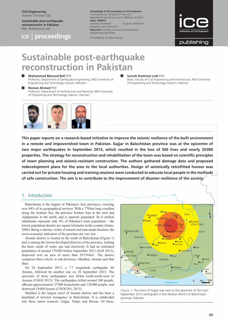
89
1. Introduction
Balochistan is the largest of Pakistan’s four provinces, covering over 44% of its geographical territory. With a 770 km long coastline along the Arabian Sea, the province borders Iran in the west and Afghanistan in the north, and is sparsely populated. Its 8 million inhabitants represent only 4% of Pakistan’s total population – the lowest population density per square kilometre in the country (Grare, 2006). Being a chronic victim of natural and man-made disasters, the socio-economic indicators of the province are very low.
Awaran district is located in the south of Balochistan (Figure 1) and is among the lowest-developed districts of the province, lacking the basic needs of water, gas and electricity. It had an estimated population of around 178 660 before September 2013 (GoP, 2012), dispersed over an area of more than 29 510 km2. The district comprises three tehsils or sub-divisions: Mashkai, Awaran and Jhal Jhao.
On 24 September 2013, a 7·7 magnitude earthquake hit Awaran, followed by another one on 28 September 2013. The epicentre of these earthquakes was 66 km north-north-west of Awaran (USGS 2013). The earthquakes killed around 500 people, affected approximately 27 000 households and 138 000 people, and destroyed 19 688 houses (UNOCHA, 2013).
Mashkai is the largest tehsil of Awaran district and has been a heartland of terrorist insurgency in Balochistan. It is subdivided into three union councils: Gajjar, Nokjo and Parwar. Of these,
Sustainable post-earthquake reconstruction in Pakistan1 Muhammad Masood Rafi PhD
Professor, Department of Earthquake Engineering, NED University of Engineering and Technology, Karachi, Pakistan
2 Noman Ahmed PhDProfessor, Department of Architecture and Planning, NED University of Engineering and Technology, Karachi, Pakistan
3 Sarosh Hashmat Lodi PhDDean, Faculty of Civil Engineering and Architecture, NED University of Engineering and Technology, Karachi, Pakistan
This paper reports on a research-based initiative to improve the seismic resilience of the built environment
in a remote and impoverished town in Pakistan. Gajjar in Balochistan province was at the epicentre of
two major earthquakes in September 2013, which resulted in the loss of 500 lives and nearly 20 000
properties. The strategy for reconstruction and rehabilitation of the town was based on scientific principles
of town planning and seismic-resistant construction. The authors gathered damage data and proposed
redevelopment plans for the area to the local authorities. Design of seismically retrofitted houses was
carried out for private housing and training sessions were conducted to educate local people in the methods
of safe construction. The aim is to contribute to the improvement of disaster resilience of the society.
Proceedings of the Institution of Civil EngineersCivil Engineering 170 May 2017 Issue CE2Pages 89–95 http://dx.doi.org/10.1680/jcien.16.00015Paper 1600015Received 21/04/2016 Accepted 14/09/2016Published online 18/10/2016Keywords: buildings, structures & design/seismic engineering/sustainability
Civil EngineeringVolume 170 Issue CE2
Sustainable post-earthquake reconstruction in PakistanRafi, Ahmed and Lodi
ICE Publishing: All rights reserved
1 2 3
km 5000Arabian Sea
NagMugalgor
Tagas
Shahbaz Kalat
Hoshab
Ormara
Basol
Gadag Bent
DadigorKarochi Tangi
PANJGUR
NAAL
WADH
BELA
KECH
PASNI
RAKHSHANJebri
PelarRustamKhan Shahr
Sher Kalat
Kandrach
Kauri
Kukari Bent
Jhal JhaoShank
Chagai
Bela
Lakhra
UthalLiari
Kathor
Soniani
MalarBazdar
AwaranBedidat
Kandgin Chuaki
Mashkai Gajjar7·7 Mw earthquake
AWARAN
Figure 1. The town of Gajjar was next to the epicentre of the main September 2013 earthquake in the Awaran district of Balochistan province, Pakistan
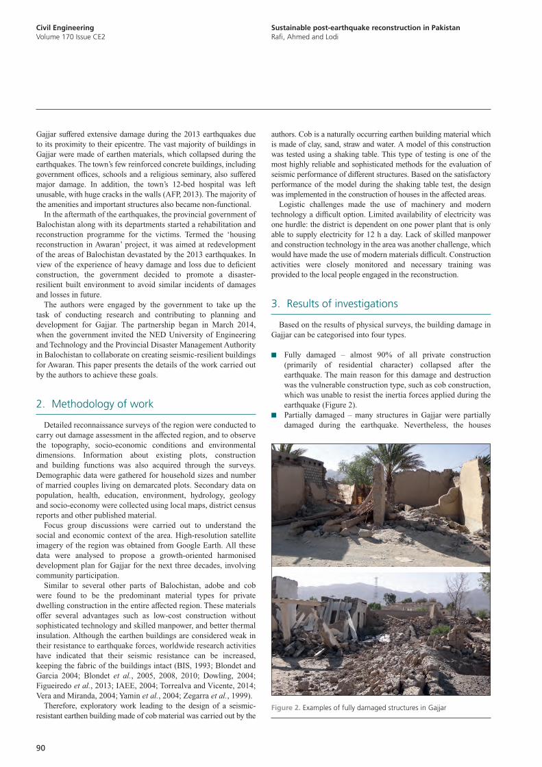
Civil EngineeringVolume 170 Issue CE2
Sustainable post-earthquake reconstruction in PakistanRafi, Ahmed and Lodi
90
authors. Cob is a naturally occurring earthen building material which is made of clay, sand, straw and water. A model of this construction was tested using a shaking table. This type of testing is one of the most highly reliable and sophisticated methods for the evaluation of seismic performance of different structures. Based on the satisfactory performance of the model during the shaking table test, the design was implemented in the construction of houses in the affected areas.
Logistic challenges made the use of machinery and modern technology a difficult option. Limited availability of electricity was one hurdle: the district is dependent on one power plant that is only able to supply electricity for 12 h a day. Lack of skilled manpower and construction technology in the area was another challenge, which would have made the use of modern materials difficult. Construction activities were closely monitored and necessary training was provided to the local people engaged in the reconstruction.
3. Results of investigations
Based on the results of physical surveys, the building damage in Gajjar can be categorised into four types.
■ Fully damaged – almost 90% of all private construction (primarily of residential character) collapsed after the earthquake. The main reason for this damage and destruction was the vulnerable construction type, such as cob construction, which was unable to resist the inertia forces applied during the earthquake (Figure 2).
■ Partially damaged – many structures in Gajjar were partially damaged during the earthquake. Nevertheless, the houses
Gajjar suffered extensive damage during the 2013 earthquakes due to its proximity to their epicentre. The vast majority of buildings in Gajjar were made of earthen materials, which collapsed during the earthquakes. The town’s few reinforced concrete buildings, including government offices, schools and a religious seminary, also suffered major damage. In addition, the town’s 12-bed hospital was left unusable, with huge cracks in the walls (AFP, 2013). The majority of the amenities and important structures also became non-functional.
In the aftermath of the earthquakes, the provincial government of Balochistan along with its departments started a rehabilitation and reconstruction programme for the victims. Termed the ‘housing reconstruction in Awaran’ project, it was aimed at redevelopment of the areas of Balochistan devastated by the 2013 earthquakes. In view of the experience of heavy damage and loss due to deficient construction, the government decided to promote a disaster-resilient built environment to avoid similar incidents of damages and losses in future.
The authors were engaged by the government to take up the task of conducting research and contributing to planning and development for Gajjar. The partnership began in March 2014, when the government invited the NED University of Engineering and Technology and the Provincial Disaster Management Authority in Balochistan to collaborate on creating seismic-resilient buildings for Awaran. This paper presents the details of the work carried out by the authors to achieve these goals.
2. Methodology of work
Detailed reconnaissance surveys of the region were conducted to carry out damage assessment in the affected region, and to observe the topography, socio-economic conditions and environmental dimensions. Information about existing plots, construction and building functions was also acquired through the surveys. Demographic data were gathered for household sizes and number of married couples living on demarcated plots. Secondary data on population, health, education, environment, hydrology, geology and socio-economy were collected using local maps, district census reports and other published material.
Focus group discussions were carried out to understand the social and economic context of the area. High-resolution satellite imagery of the region was obtained from Google Earth. All these data were analysed to propose a growth-oriented harmonised development plan for Gajjar for the next three decades, involving community participation.
Similar to several other parts of Balochistan, adobe and cob were found to be the predominant material types for private dwelling construction in the entire affected region. These materials offer several advantages such as low-cost construction without sophisticated technology and skilled manpower, and better thermal insulation. Although the earthen buildings are considered weak in their resistance to earthquake forces, worldwide research activities have indicated that their seismic resistance can be increased, keeping the fabric of the buildings intact (BIS, 1993; Blondet and Garcia 2004; Blondet et al., 2005, 2008, 2010; Dowling, 2004; Figueiredo et al., 2013; IAEE, 2004; Torrealva and Vicente, 2014; Vera and Miranda, 2004; Yamin et al., 2004; Zegarra et al., 1999).
Therefore, exploratory work leading to the design of a seismic-resistant earthen building made of cob material was carried out by the
Figure 2. Examples of fully damaged structures in Gajjar
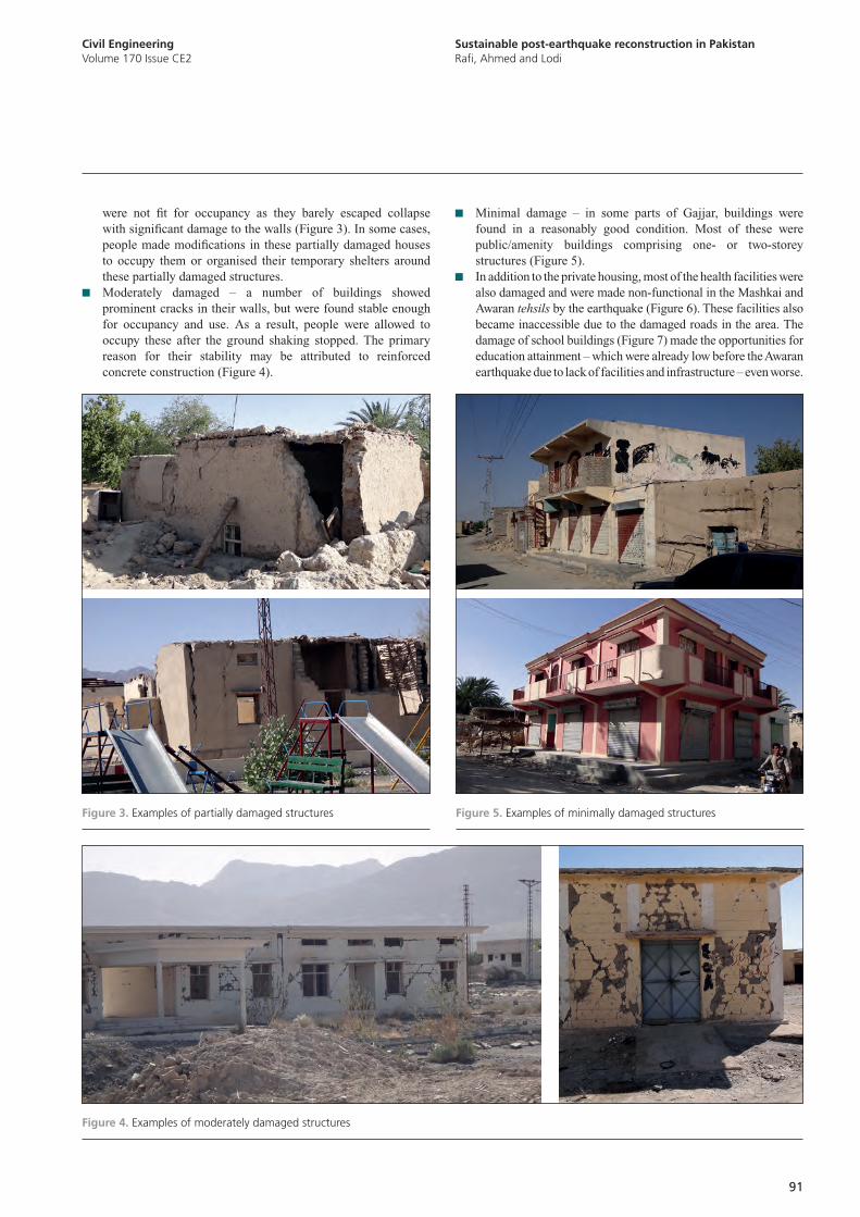
Sustainable post-earthquake reconstruction in PakistanRafi, Ahmed and Lodi
Civil EngineeringVolume 170 Issue CE2
91
■ Minimal damage – in some parts of Gajjar, buildings were found in a reasonably good condition. Most of these were public/amenity buildings comprising one- or two-storey structures (Figure 5).
■ In addition to the private housing, most of the health facilities were also damaged and were made non-functional in the Mashkai and Awaran tehsils by the earthquake (Figure 6). These facilities also became inaccessible due to the damaged roads in the area. The damage of school buildings (Figure 7) made the opportunities for education attainment – which were already low before the Awaran earthquake due to lack of facilities and infrastructure – even worse.
were not fit for occupancy as they barely escaped collapse with significant damage to the walls (Figure 3). In some cases, people made modifications in these partially damaged houses to occupy them or organised their temporary shelters around these partially damaged structures.
■ Moderately damaged – a number of buildings showed prominent cracks in their walls, but were found stable enough for occupancy and use. As a result, people were allowed to occupy these after the ground shaking stopped. The primary reason for their stability may be attributed to reinforced concrete construction (Figure 4).
Figure 3. Examples of partially damaged structures
Figure 4. Examples of moderately damaged structures
Figure 5. Examples of minimally damaged structures
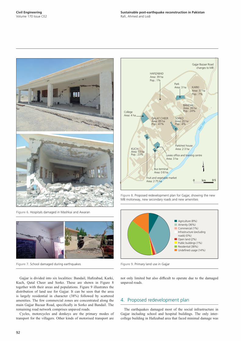
Civil EngineeringVolume 170 Issue CE2
Sustainable post-earthquake reconstruction in PakistanRafi, Ahmed and Lodi
92
not only limited but also difficult to operate due to the damaged unpaved roads.
4. Proposed redevelopment plan
The earthquakes damaged most of the social infrastructure in Gajjar including school and hospital buildings. The only inter-college building in Hafizabad area that faced minimal damage was
Gajjar is divided into six localities: Bandail, Hafizabad, Karki, Kuch, Qatal Cheer and Sorko. These are shown in Figure 8 together with their areas and populations. Figure 9 illustrates the distribution of land use for Gajjar. It can be seen that the area is largely residential in character (38%) followed by scattered amenities. The few commercial zones are concentrated along the main Gajjar Bazaar Road, specifically in Sorko and Bandail. The remaining road network comprises unpaved roads.
Cycles, motorcycles and donkeys are the primary modes of transport for the villagers. Other kinds of motorised transport are
Figure 6. Hospitals damaged in Mashkai and Awaran
Figure 7. School damaged during earthquakes
KUCHArea: 53 haPop.: 23%
QALAT CHEERArea: 89 haPop.: 41%
SORKOArea: 20 haPop.: 4%
Meh
War
BANDAILArea: 39 haPop.: 24%
HAFIZABADArea: 39 haPop.: 1%
KARKIArea: 37 haPop.: 7%
Fruit and vegetable marketArea: 2.75 ha
Bus terminalArea: 0.8 ha
Levies office and training centreArea: 3 ha
CollegeArea: 4 ha
Park/rest houseArea: 2.3 ha
ParkArea: 3 ha
Gajjar Bazaar Roadchanges to M8
km 0.50
Figure 8. Proposed redevelopment plan for Gajjar, showing the new M8 motorway, new secondary roads and new amenities
Agriculture (8%)Amenity (36%)Commercial (1%)Infrastructure (excludingroads) (0%)Open land (2%)Public buildings (1%)Residential (38%)Undefined usage (14%)
Figure 9. Primary land use in Gajjar
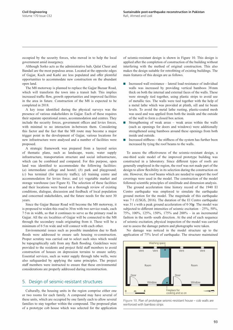
Sustainable post-earthquake reconstruction in PakistanRafi, Ahmed and Lodi
Civil EngineeringVolume 170 Issue CE2
93
of seismic-resistant design is shown in Figure 10. This design is applied after the completion of construction of the building without interfering with the method of original construction. This also makes the design suitable for retrofitting of existing buildings. The main features of this design are as follows.
■ Increased wall resistance – lateral load resistance of individual walls was increased by providing vertical bamboos 38 mm thick on both the internal and external faces of the walls. These were strongly tied together, using plastic strips to avoid use of metallic ties. The walls were tied together with the help of a metal lathe which was provided at plinth, sill and tie beam levels. To avoid the metal lathe rusting, plastic-coated mesh was used and was applied from both the inside and the outside of the wall to form a closed box action.
■ Strengthening of weak areas – weak areas within the walls (such as openings for doors and windows) were additionally strengthened using bamboos around these openings from both inside and outside.
■ Increased stiffness – the stiffness of the system has further been increased by tying the roof beams to the walls.
To assess the effectiveness of the seismic-resistant design, a one-third scale model of the improved prototype building was constructed in a laboratory. Since different types of roofs are generally employed in the region, the roof was not made part of the design to allow flexibility in its selection during the construction on site. However, the roof beams which are needed to support the roof coverings were used in the model. The construction of the model followed scientific principles of similitude and dimension analysis.
The ground acceleration time history record of the 1940 El Centro earthquake was employed to simulate the earthquake ground motion for the model. The magnitude of this earthquake was 7·1 (USGS, 2016). The duration of the El Centro earthquake was 31 s with a peak ground acceleration of 0·30g. The model was subjected to different intensities of seismic excitation – 25%, 50%, 75%, 100%, 125%, 150%, 175% and 200% – in an incremental fashion in the north–south direction. At the end of each sequence of seismic excitation, physical inspection of the model was carried out to assess the damage pattern and photographs were taken.
No damage was noticed in the model structure up to the application of 75% level of earthquake. The structure maintained
occupied by the security forces, who moved in to help the local government amid insurgency.
Although Sorko acts as the administrative hub, Qalat Cheer and Bandail are the most populous areas. Located at the opposite edges of Gajjar, Kuch and Karki are less populated and offer plentiful opportunities to accommodate new construction on the abundant open land.
The M8 motorway is planned to replace the Gajjar Bazaar Road, which will transform the town into a transit hub. This implies increased traffic flow, growth opportunities and improved facilities in the area in future. Construction of the M8 is expected to be completed in 2018.
A key issue identified during the physical surveys was the presence of various stakeholders in Gajjar. Each of these requires their separate operational zones, accommodation and centres. They include the security forces, government offices and levies forces, with minimal to no interaction in-between them. Considering this factor and the fact that the M8 route may become a major trigger point in the development of Gajjar, various locations for new infrastructure were analysed and a number of facilities were proposed.
A strategic framework was prepared from a layered series of thematic plans, such as landscape, waste, water supply infrastructure, transportation structure and social infrastructure, which can be combined and compared. For this purpose, open land was identified to accommodate the following facilities: (a) intermediate college and hostel; (b) park and playground; (c) bus terminal (for intercity traffic); (d) training centre and accommodation for levies force; and (e) vegetable market and storage warehouse (see Figure 8). The selection of these facilities and their locations were based on a thorough review of existing conditions, dialogue, discussion and feedback of local population and concerned stakeholders, and the future needs for the next 30 years.
Since the Gajjar Bazaar Road will become the M8 motorway, it is proposed to widen this road to 30 m with two service roads, each 7·5 m in width, so that it continues to serve as the primary road in Gajjar. All the six localities of Gajjar will be connected to the M8 through the secondary roads originating from it. These will be a minimum of 6·5 m wide and will connect with each other.
Environmental issues such as possible inundation due to flash floods were addressed to ensure safe housing re-construction. Proper scrutiny was carried out to select such sites which would be topographically safe from any flash flooding. Guidelines were provided to the residents and project field staff members to avoid construction of houses on depression terrains to ensure safety. Essential services, such as water supply through tube wells, were also safeguarded by applying the same principles. The project staff members were instructed to ensure that these environmental considerations are properly addressed during reconstruction.
5. Design of seismic-resistant structures
Culturally, the housing units in the region comprise either one or two rooms for each family. A compound may have several of these units, which are occupied by one family each to allow several families to stay together within the compound. The proposed plan of a prototype cob house which was selected for the application
WindowWindow
Vent Vent Vent Vent
Door Door
Room Room
Washing space
Fireplace forcooking and so on
m 40
Figure 10. Plan of prototype seismic-resistant house – cob walls are reinforced with bamboo strips
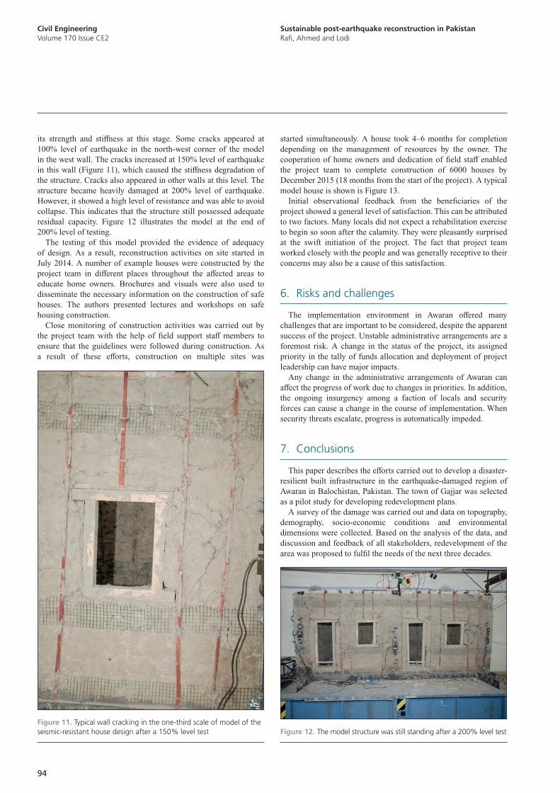
Civil EngineeringVolume 170 Issue CE2
Sustainable post-earthquake reconstruction in PakistanRafi, Ahmed and Lodi
94
started simultaneously. A house took 4–6 months for completion depending on the management of resources by the owner. The cooperation of home owners and dedication of field staff enabled the project team to complete construction of 6000 houses by December 2015 (18 months from the start of the project). A typical model house is shown is Figure 13.
Initial observational feedback from the beneficiaries of the project showed a general level of satisfaction. This can be attributed to two factors. Many locals did not expect a rehabilitation exercise to begin so soon after the calamity. They were pleasantly surprised at the swift initiation of the project. The fact that project team worked closely with the people and was generally receptive to their concerns may also be a cause of this satisfaction.
6. Risks and challenges
The implementation environment in Awaran offered many challenges that are important to be considered, despite the apparent success of the project. Unstable administrative arrangements are a foremost risk. A change in the status of the project, its assigned priority in the tally of funds allocation and deployment of project leadership can have major impacts.
Any change in the administrative arrangements of Awaran can affect the progress of work due to changes in priorities. In addition, the ongoing insurgency among a faction of locals and security forces can cause a change in the course of implementation. When security threats escalate, progress is automatically impeded.
7. Conclusions
This paper describes the efforts carried out to develop a disaster-resilient built infrastructure in the earthquake-damaged region of Awaran in Balochistan, Pakistan. The town of Gajjar was selected as a pilot study for developing redevelopment plans.
A survey of the damage was carried out and data on topography, demography, socio-economic conditions and environmental dimensions were collected. Based on the analysis of the data, and discussion and feedback of all stakeholders, redevelopment of the area was proposed to fulfil the needs of the next three decades.
its strength and stiffness at this stage. Some cracks appeared at 100% level of earthquake in the north-west corner of the model in the west wall. The cracks increased at 150% level of earthquake in this wall (Figure 11), which caused the stiffness degradation of the structure. Cracks also appeared in other walls at this level. The structure became heavily damaged at 200% level of earthquake. However, it showed a high level of resistance and was able to avoid collapse. This indicates that the structure still possessed adequate residual capacity. Figure 12 illustrates the model at the end of 200% level of testing.
The testing of this model provided the evidence of adequacy of design. As a result, reconstruction activities on site started in July 2014. A number of example houses were constructed by the project team in different places throughout the affected areas to educate home owners. Brochures and visuals were also used to disseminate the necessary information on the construction of safe houses. The authors presented lectures and workshops on safe housing construction.
Close monitoring of construction activities was carried out by the project team with the help of field support staff members to ensure that the guidelines were followed during construction. As a result of these efforts, construction on multiple sites was
Figure 11. Typical wall cracking in the one-third scale of model of the seismic-resistant house design after a 150% level test Figure 12. The model structure was still standing after a 200% level test
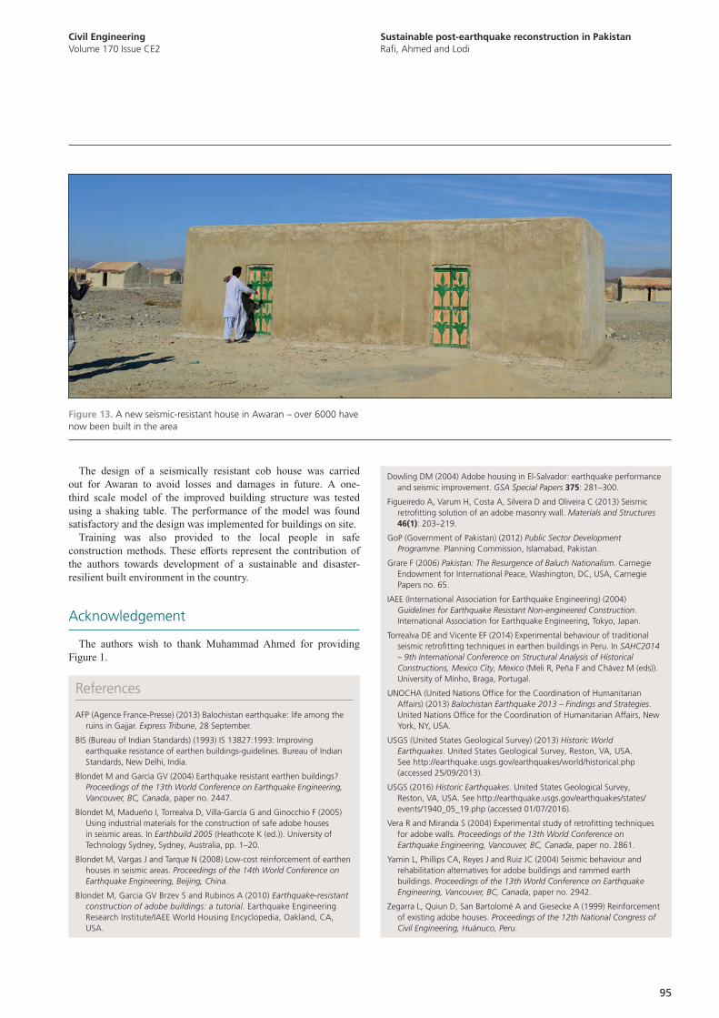
Sustainable post-earthquake reconstruction in PakistanRafi, Ahmed and Lodi
Civil EngineeringVolume 170 Issue CE2
95
Dowling DM (2004) Adobe housing in El-Salvador: earthquake performance and seismic improvement. GSA Special Papers 375: 281–300.
Figueiredo A, Varum H, Costa A, Silveira D and Oliveira C (2013) Seismic retrofitting solution of an adobe masonry wall. Materials and Structures 46(1): 203–219.
GoP (Government of Pakistan) (2012) Public Sector Development Programme. Planning Commission, Islamabad, Pakistan.
Grare F (2006) Pakistan: The Resurgence of Baluch Nationalism. Carnegie Endowment for International Peace, Washington, DC, USA, Carnegie Papers no. 65.
IAEE (International Association for Earthquake Engineering) (2004) Guidelines for Earthquake Resistant Non-engineered Construction. International Association for Earthquake Engineering, Tokyo, Japan.
Torrealva DE and Vicente EF (2014) Experimental behaviour of traditional seismic retrofitting techniques in earthen buildings in Peru. In SAHC2014 – 9th International Conference on Structural Analysis of Historical Constructions, Mexico City, Mexico (Meli R, Peña F and Chávez M (eds)). University of Minho, Braga, Portugal.
UNOCHA (United Nations Office for the Coordination of Humanitarian Affairs) (2013) Balochistan Earthquake 2013 – Findings and Strategies. United Nations Office for the Coordination of Humanitarian Affairs, New York, NY, USA.
USGS (United States Geological Survey) (2013) Historic World Earthquakes. United States Geological Survey, Reston, VA, USA. See http://earthquake.usgs.gov/earthquakes/world/historical.php (accessed 25/09/2013).
USGS (2016) Historic Earthquakes. United States Geological Survey, Reston, VA, USA. See http://earthquake.usgs.gov/earthquakes/states/events/1940_05_19.php (accessed 01/07/2016).
Vera R and Miranda S (2004) Experimental study of retrofitting techniques for adobe walls. Proceedings of the 13th World Conference on Earthquake Engineering, Vancouver, BC, Canada, paper no. 2861.
Yamin L, Phillips CA, Reyes J and Ruiz JC (2004) Seismic behaviour and rehabilitation alternatives for adobe buildings and rammed earth buildings. Proceedings of the 13th World Conference on Earthquake Engineering, Vancouver, BC, Canada, paper no. 2942.
Zegarra L, Quiun D, San Bartolomé A and Giesecke A (1999) Reinforcement of existing adobe houses. Proceedings of the 12th National Congress of Civil Engineering, Huánuco, Peru.
The design of a seismically resistant cob house was carried out for Awaran to avoid losses and damages in future. A one-third scale model of the improved building structure was tested using a shaking table. The performance of the model was found satisfactory and the design was implemented for buildings on site.
Training was also provided to the local people in safe construction methods. These efforts represent the contribution of the authors towards development of a sustainable and disaster-resilient built environment in the country.
Acknowledgement
The authors wish to thank Muhammad Ahmed for providing Figure 1.
References
AFP (Agence France-Presse) (2013) Balochistan earthquake: life among the ruins in Gajjar. Express Tribune, 28 September.
BIS (Bureau of Indian Standards) (1993) IS 13827:1993: Improving earthquake resistance of earthen buildings-guidelines. Bureau of Indian Standards, New Delhi, India.
Blondet M and Garcia GV (2004) Earthquake resistant earthen buildings? Proceedings of the 13th World Conference on Earthquake Engineering, Vancouver, BC, Canada, paper no. 2447.
Blondet M, Madueño I, Torrealva D, Villa-García G and Ginocchio F (2005) Using industrial materials for the construction of safe adobe houses in seismic areas. In Earthbuild 2005 (Heathcote K (ed.)). University of Technology Sydney, Sydney, Australia, pp. 1–20.
Blondet M, Vargas J and Tarque N (2008) Low-cost reinforcement of earthen houses in seismic areas. Proceedings of the 14th World Conference on Earthquake Engineering, Beijing, China.
Blondet M, Garcia GV Brzev S and Rubinos A (2010) Earthquake-resistant construction of adobe buildings: a tutorial. Earthquake Engineering Research Institute/IAEE World Housing Encyclopedia, Oakland, CA, USA.
Figure 13. A new seismic-resistant house in Awaran – over 6000 have now been built in the area

ICE Publishing selected ten papers, to illustrate the richness of that scholarship, as it applies to many of the great engineering projects of modern times; projects designed and built, usually by ICE members, all over the world. The papers are now free to read in perpetuity.
n Stadium Australia
n The Statue of Liberty, USA
n Panama Canal
n Akashi-Kakyo Bridge, Japan
n Three Gorges Project, China
n Kolkata’s Brick Sewers, India
n Hong Kong Airport
n Four Rivers Project, Korea
n The Suez Canal, Egypt
n The Channel Tunnel, France
In the nearly two centuries since the first issue of Transactions of the Institution of Civil Engineers was published in 1836, the ICE has published some of the most important work in the fields of civil engineering and construction.
Visit this page to download the free papers: www.icevirtuallibrary.com/page/ice-about/marquee-projects
Monuments of Modern Engineering

Why publish with ICE?
Access to ICE membership – ICE Publishing, as
the publishing arm of ICE, is the only publisher
that brings you direct access to ICE’s worldwide
membership of 80 000.
Visibility – we also have thousands of readers
who are not members of ICE, from corporations,
to governments, to universities. Our journals
are included in major engineering indexes and
resources.
Quality – our journals’ reputation for quality
is unsurpassed, ensuring that the originality,
authority and accuracy of your work will be fully
recognised.
Support – if your paper is accepted, you will have
a dedicated editorial contact who will handle all of
your enquiries and provide you with guidance on
writing your paper.
Marketing – our marketing team has extensive
experience of working with author and librarian
communities to make sure your work is seen by
people who matter, including top academics,
industry leaders, companies and institutions.
Proceedings of the Institution of Civil Engineers
Civil Engineering SPECIAL ISSUE
Editors: Andrew Martin, COWI, Denmark and Colin Rawlings, CH2M/High Speed Two (HS2), UK
Call for PapersMajor and innovative projects in the Nordic countries
Jan
Ko
fod
Win
ther
, Øre
sun
dsb
ron
Civil Engineering is planning a special issue for May 2018 on major and innovative projects in the Nordic countries.
Recent and ongoing major projects in the Nordic countries illustrate innovation in
design, construction, operation and maintenance across many of the disciplines of
civil engineering, delivering environmental, social and economic benefits to society
to local communities and to the wider world.
Sweden, Norway, Denmark (including the Faroes and Greenland), Finland and
Iceland share the challenges of colder climates and large inter-urban distances,
together with opportunities for sustainable growth and regeneration in major
towns and cities, which have inspired and driven forward large and innovative civil
engineering projects.
This special issue of Civil Engineering will allow the experience of some of these
projects to be shared with the engineering community worldwide.
Projects of particular interest include, but are not limited to
n Airport expansion
n Cold climate engineering
n Engineered timber
n Floating bridges and tunnels
n Geothermal energy plant
n High-speed railways
n Hydropower
n Metros and urban light rail
n Offshore and onshore wind energy
n Ports and harbours
n Rock engineering
n Waste-to-energy
The deadline for submissions is 12 June 2017.
Invitation to authorsTo submit an abstract please visit
https://goo.gl/forms/TKJowPaG89H2nzIC2To submit a full paper please visit www.editorialmanager.com/ce
For further information and full journal guidelines, please contact
Ben Ramster T: +44 20 7665 2242; E: [email protected]
For more information about the journal, please visit www.icevirtuallibrary.com

The Archives contain over 350 project papers, including important papers on:
n the Channel Tunnel
n the Thames Water ring
n Sizewell B power station
n Heathrow Terminal 5
Your purchase will provide you with perpetual digital access.
Published twice per year in May and November, Civil Engineering Special Issues (CESI) provide an indispensable record of recent major projects, such as the London Olympics.
Beginning in 2017, CESI subscribers will benefit from online access to exclusive project-related video content created by the authors and editors.
Digital Archives of the first 41 Civil Engineering Special Issues, published from 1992-2012, are available for purchase
For more information and to order, please contact us at
ICE Members: Email: [email protected]; Tel: +44 (0)20 7665 2227
Non-Members: Email: [email protected]; Tel: +44 (0)20 7665 2460
Civil Engineering Special Issues (CESI) Archives
Civil Engineering Special Issues (CESI)