civl 7904/8904: traffic flow theory (spring 2014) april 5
TRANSCRIPT
CIVL 7904/8904: Traffic Flow Theory (Spring 2014)
April 5, 2014
Ioannis Psarros Department of Civil Engineering and Intermodal Freight Transportation
Institute, Memphis, TN

Transportation Research Increased demand has created major problems (e.g.
congestion, delays, etc.) in traffic operations
To mitigate these problems further research in the transportation area is needed
Various software platforms can be used as significant tools in carrying out this research

Analysis Level Major Categories
Traffic Simulation: Modeling of individual vehicles movements in a micro level
to assess the traffic performance of highway and street systems, transit and pedestrians.
Planning & Demand Forecasting: Application of forecasting models to develop a long range
transportation plan. These models calculate the number of trips, connect origins with destinations, predict the travel
mode and identify the routes to complete the trips.

Major Planning Software
Aimsun
TransCAD
CUBE
Visum
Planning- Demand Modeling
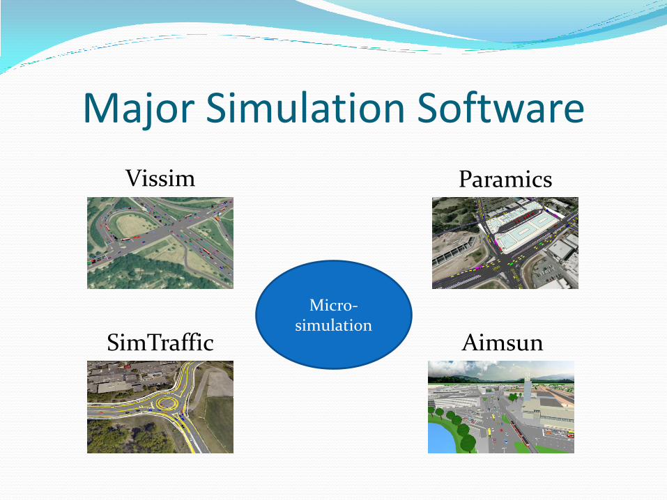
Major Simulation Software
Aimsun
Vissim
SimTraffic
Paramics
Micro- simulation

Paramics Developed by Quadstone Paramics
Introduced in 1990s by the UK Department for Transport
Simulate individual vehicle at the micro level
Simulate the impact of future travel pattern
6
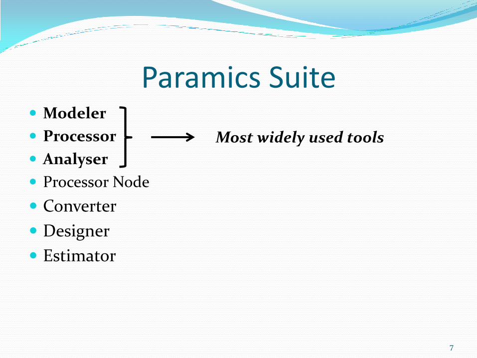
Paramics Suite Modeler
Processor
Analyser
Processor Node
Converter
Designer
Estimator
7
Most widely used tools
Processor Node
8
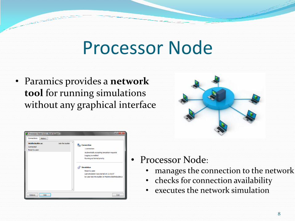
• Paramics provides a network tool for running simulations without any graphical interface
• Processor Node:
• manages the connection to the network • checks for connection availability • executes the network simulation

Converter “Convert” networks from other sources
Input file data can include: GIS shapefiles
SYNCHRO networks
CSV files
CORSIM Networks
EMME/2 Networks
Cube Networks
9
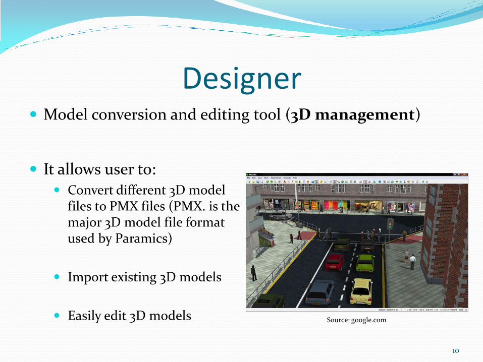
Designer Model conversion and editing tool (3D management)
10
Source: google.com
It allows user to: Convert different 3D model
files to PMX files (PMX. is the major 3D model file format used by Paramics)
Import existing 3D models
Easily edit 3D models

Estimator Additional tool for OD matrix estimation
“Reverse” OD matrix estimation
OD matrices estimation from count data (link, intersections)
11

Modeler Main tool
It provides 4 fundamental operations: Building the network (geometry, link speeds, junctions rules and
priorities, traffic signals)
Editing demand (zones, OD matrix, demand profile)
Simulating traffic (with 3D visualization)
Estimating MOEs using detectors
12

I-40 in Paramics Modeler
13
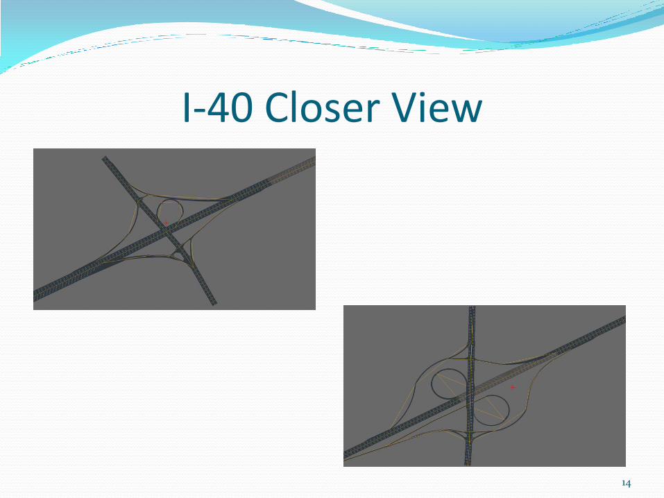
I-40 Closer View
14
Processor Tool for running simulations without any graphical
interface (see Processor Node)
Processor allows user to: Specify parameters of the simulation runs (start time, duration,
vehicle types considered, statistics collection duration
Determine number of simulations
Determine seed generation
15

Analyser Determines statistics to be gathered during simulation
You can have: Outcomes per vehicle type
Results for specific road segments (use detectors)
Results for specific routes
Outputs include: Speed, flow, volume, delay, LOS, queue length, trip time, etc.
16

Developing a Model in Modeller Step 1: New network wizard..
Step 2: Create the network geometry
Step 3: Fix traffic signals if needed
Step 4: Identify the zones of the case study area
Step 5: Develop vehicle templates and load OD matrix with travel demand
Step 6: Run the simulation..
17
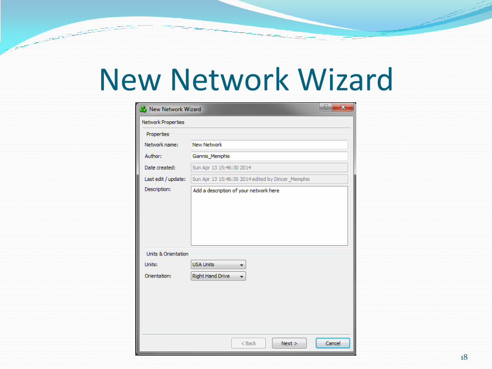
New Network Wizard
18
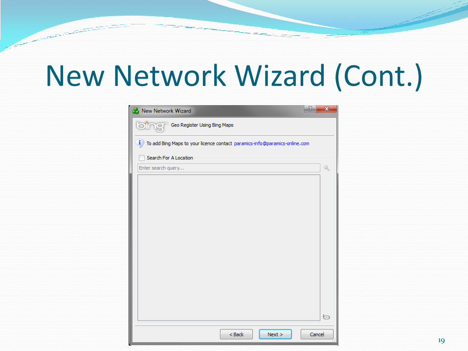
New Network Wizard (Cont.)
19

Creating Network Geometry Place the junction (intersections) of the network
Create the links and edit their characteristics (link type and number of lanes, speed limit, signpost, etc.)
Edit lane attributes (specify lane closures, restrictions, speed controls, etc.)
Fix the geometry of the network links using control points
Fix movements at junctions (congestion due to unnecessary lane changing)
20

21
Junction Editing
Create/delete junctions
Node Type: • Normal • Roundabout • Ghost island (split of a
2 lane segment to 2 separate single lane roadways)
• Zone connector

Link Editing Link characteristics:
Number of lanes
Speed limit
Link type:
Highway
Signalised
Weaving area
Ramp
22
Existence of hazard (turn, narrowing, etc.) and when the driver becomes aware of it
Having identified the junctions of the network, you can create links to connect them

Editing Lane Attributes Determine for each
lane:
Any restrictions
Any speed control
Stop time at link end (simulate tolls)
Headway/reaction factor for adjusting vehicles behavior)
23

Modelling Restrictions
24

Control Points!!!
25

Editing Movements!!!
26

Fixing Traffic Signals After pressing
Signalize button a template is developed
This template is wrong!
You have to adjust:
Number of Phases
Movements allowed or barred in each phase
Signal timings per phase
You can also model Actuated Signal Control
27

Fixed Traffic Signal
28

Zones of the Study Area Zones can produce
/attract (or both) trips, depending on the borders of the zone
Zone types: Vehicle sink
Car parking
Waypoints
Zone borders in red, zone doesn’t work properly
Tools for creating /deleting zones
29

Vehicle Templates Vehicles can be edited
using: New network wizard
(at the beginning)
Core network attributes
Vehicle characteristics can be edited
UK vehicle templates provided: Car
LGV
OGV1 and 2
Bus/Minibus
Coach
User specified
30

Vehicle templates
31
Demand Editor Demand editing: the significant part of developing an
accurate simulation model
Remember Static VS Dynamic traffic assignment!!!!!!
It allows user to:
Import/export OD matrices with traffic demand per vehicle type
Edit the demand profile (distribution of volume per time interval)
32
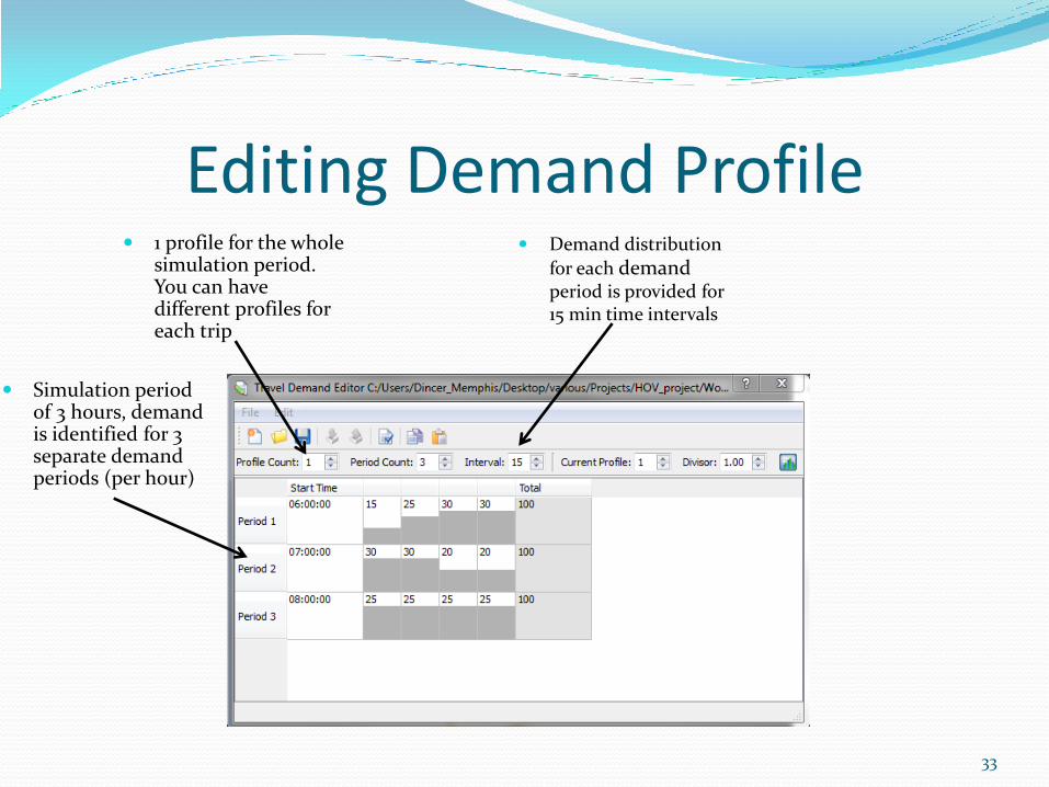
Editing Demand Profile
Simulation period of 3 hours, demand is identified for 3 separate demand periods (per hour)
33
Demand distribution
for each demand period is provided for 15 min time intervals
1 profile for the whole simulation period. You can have different profiles for each trip

Editing Demands You can have 1 demand
period for the whole simulation period or split it (e.g. demand/hour)
34
Total matrix number for each demand period
For high volumes you can divide the volume numbers
Specify one matrix per vehicle type for each demand period
Traffic demand is usually provided by TransCAD software

Different Profiles for each Trip 2 separate profiles
for 1 period
35
This is the second profile
Need to assign a profile for each trip?

Profile Assignment Matrix Assigning
profiles to trips
36

Simulation in Paramics-1 Visual simulation using Modeller
Visual representation of vehicles movements
Easy way to identify potential errors (e.g. hotspot viewer)
Difficulties in producing simulation outputs
Time consuming
37
Simulation in Paramics-2 Simulation using Processor
No visual representation
Faster way to accomplish a large number of simulations for the same network
Compatibility with Analyser tool for faster production of simulation outputs
38

Simulation with Processor-1
Demand factor allows the adjustment of demand to capture future conditions
39
Start time and duration of simulation
Random number Generator for seeds (determined later)
Manages costs related to vehicles routes and vehicle travel behavior (use default values)
Upload network

Simulation with Processor-2 Determine for
Statistics: Collection warm
up time
Collection duration
Gather interval
40
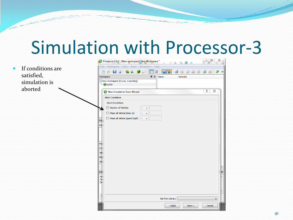
Simulation with Processor-3 If conditions are
satisfied, simulation is aborted
41

Simulation with Processor-4
Number of simulations
42

Analyser for Outputs-1
Upload the network
43
Include all the related simulations

Analyser for Outputs-2 Network
visualization
44
Create outputs for specific nodes, links, detectors..
Crate outputs per vehicle type
Place limits on the values of outputs to be displayed
Outputs for specific groups of links or routes
Choose the MOEs to be estimated

Thank you for your attention
Q/A
45