cjc oil filtration system 2
TRANSCRIPT

8/9/2019 CJC Oil Filtration System 2
http://slidepdf.com/reader/full/cjc-oil-filtration-system-2 1/25
CJC™ OilEfficient removalby-products from
u
(r
Filtration Systemsof particles, water and oxidationoil and hydraulic fluids
h
w m W o 4 ® o S k
(Miii©§aD@@§3ri teB|S7y
O Visit b y Technical TeamO Analysis o f requirementsO Research DevelopmentO il sample analysis service<> Information: www.cjc. dk
\ ^ Z
<> Technical advice back-up<0 Short a n d on-time deliveryO Installation o f CJC™ filtersO Test a n d serviceO il analysis after installation
C* Continuous o il analysisO F/7fer insert change service
1 O Quick spare part serviceO Service centers world wide"O Technical advice back-up

8/9/2019 CJC Oil Filtration System 2
http://slidepdf.com/reader/full/cjc-oil-filtration-system-2 2/25
Manufacturer
C C JENSEN A/S * L0vholmen 13 * DK-5700 Svendborg * DenmarkPhone: +45 63 21 20 14 * Fax: +45 62 22 46 15 * E-mail: [email protected]
Manual no.: FH7602104(-uk)
OPERATING MANUAL
CJC Offline Fine FilterHDU 2 7/- MZ
Production no: 1648050301
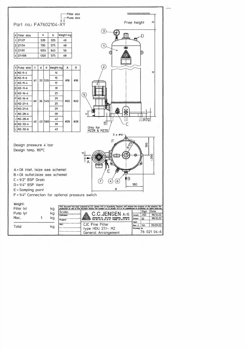
Technical SpecificationsType
Model
Filter insert
General arr./Assembly drw.
Pump
Electric motorControl box
Pressure switch
Solenoid valve
Special equipment
Noise level
CJC Offline Fine Filter
HDU 27/27 MZ
B 27/27 .
76 021 04-6 (rev. 2) / 46 020 01 -3 (rev. 2)
MZ-9-6, 455 1/h (56 022 08-4)
VEM K21R 71G6 (3 x 440 V, 60 Hz, 0.3 kW, 1.06 A)_
_
-
_
< 70 dB(A)
nly for indoor use
EU Declaration of Conformity on the last page of this book
IMO 9340582GSI 03130011

8/9/2019 CJC Oil Filtration System 2
http://slidepdf.com/reader/full/cjc-oil-filtration-system-2 3/25
Operating Instructions for J Filter Products
IMPORTANT
In order to have m aximum benefit from your CJC Filter, we suggest that you read through thisman ual's sections concerning installation and operation prior to the produc t's installation, andwhen the product is operated or serviced.
Do not hesitate to contact C.C.JENSEN A/S or your local CJC distributor for any further technical information you may require.
This manual contains information on the installation, operation, and maintenance of the CJCFilter unit based on the specifications of the unit when delivered from our factory. Theprodu ction no . is stated on the front pag e. In case post-delivery alterations have been m adeto the unit, we recom mend that you contact C.C.JEN SEN A/S or your local distributor for anupdated manual.
When ordering spare parts or requesting technical assistance, always state the production(serial) number of the CJC filter un it (see front page of manual and nam e plate on unit).
Unless special permission has been granted by C.C.JENS EN A/S do not attempt to repair ordismantle the CJC F ilter unit or any of its comp onents within the w arranty period of the unit(with exception of any dismantling necessary for the replacem ent of filter e lements). Failureto seek the said perm ission will cause the guarantee on the said parts to be void
C.C.JENSEN A/S' product liability does not cover technical modifications to the filter unitor its electrical system unless C.C.JENS EN A /S ' in writing has accepted such extension ofliability.

8/9/2019 CJC Oil Filtration System 2
http://slidepdf.com/reader/full/cjc-oil-filtration-system-2 4/25
Operating Instructions for CJC Filter Products
^W A R N ING S & CAUTIONS- health and safety hazards
The CJC F ilter unit is a machine and as such it must be inspected daily - even if CJC Filtersin general demand very little maintenance.
Alm ost all types of oil are potential threats to the environm ent and as such they must notbe drained into ordinary sewers or "dumped" in nature. Always check that all oil carryingcom ponents are sealed and tight before operating the C JC filter unit.
Be aware that oil spillage on the floor around the filter unit is a serious safety risk
Water drained from a filter separator is not clean and must not be drained to ordinarysewers, but be collected in a special container and disposed of in accordance with localregulations for oil and chem ical waste.
Used filter elements very often contain harmful substances separated from the oil. Alwayspack and seal used elements thoroughly until they can be disposed of in accordance with
local regulations for oil and chemical w aste.
The electrical power supply to the filter unit must be switched off (remove fuses ifnecessary) when carrying out maintenance , and especially before opening th e control box orthe terminal box of the electric motor. Repairs of the electrical control systems may only becarried out by trained C.C.JENSEN technicians.
Do not expose the filter unit to ambient temperatures higher than 60 °C (140 °F as this mayharm electrical wires, hoses and other rubber or synthetic com ponents
The fluid temperature inside the filter unit must never exceed 80 °C (175 °F). Higher fluidtemperatures may cause dam age to the seals and packings on and in the filter unit.

8/9/2019 CJC Oil Filtration System 2
http://slidepdf.com/reader/full/cjc-oil-filtration-system-2 5/25
Operating instructions -_1
When ordering spare parts, always statefilter type, production no. and an exactdescription of the part (drawing and item no.if any).
All item n os. mentioned below refer to drawingnos
A) 76 021 04- 6 (General arrangement)B) 46 020 01-3 (Assembly drawing)
in this book.
Connection to the SystemCJC fine filters must be c onnected to the mainsystem by independent suction and return lines.The filter suction line should be connected tothe lowest and most contaminated location ofthe system tank (very often the bottom drainplug), and the filter outlet (return) line shouldbe led back into the tank close to the suctionpipe of the system pum p - preferably below theoil surface to avoid oxidation of the oil.
The connection pipes and hoses should be asshort as possible. If conditions on the installation site demand for very long pipes the innerdiameter of the piping must be increasedaccordingly and not reduced until immediatelybefore entering the filter.
Note Never use fittings with tapered thread infilter or pump.
The electric motor and the pump are connectedto the voltage required, preferably over a motorover- load protection (not included in the CJCstandard supply). Rem ember to check at start upthat the electric motor rotates in correctdirection (indicated by arrow on fan cover).
Starting UpCheck that inlet and outlet valves (if fitted) areopen, and that the vent screw (B-7) on the filtertop are open. Then start the pum p.
Close the vent screw as soon as liquid isappearing under it (the pump will take some 15mins to fill the filter).
Vent the filter again after approximately onehour's operation (not necessary if filter is fittedwith automatic vent).
Normal OperationWhen the filter is put into operation with aclean filter insert, the pressure drop over theinsert (B-17) is insignificant.
Manual no. FH7602104(-uk)
HDU 27 /- MZ
The pressure gauge (A-3) monitors the pressuredrop over the filter insert. The pressure varieswith the oil viscosity, but is usually < 0.3 bar. Itis not unusual, however, for the pressure to besomewhat higher during the first hour ofoperation until temperature and flow conditionshave stabilized.
As impurities are deposited in and on the filterinsert the resistance against the oil flowincreases, which is monitored on the pressuregauge. When the pressure reaches 2 bar the freeflow area of the insert has been reduced to anextent that the insert must be replaced. Foradditional safety a 2.8 bar pressure relief valveis integrated in the filter pump.
Filter Insert Replacement
W hen the gauge indicates a pressure drop of 2bar the filter insert is due for replacement.Before th is can be done the filter housing ha s tobe drained.
Stop the pump and close inlet and outlet valve(if any). Untighten the vent screw and drain thehousing through the bottom drain (A-4).
After drainage unscrew the top nut (B-23) andlift off the housing. Unscrew the spring nut (B-29) and remove the spring (B-24) and the springguide (B-16). Now lift up the insert. This isdone easily by means of a CJC Insert E xtractor,which can be ordered with the new filter insert.
When all inside parts have been cleaned and allo-rings checked (B-5, B-13) the new insert canbe placed in the housing. Before pressing thespring guide in place, check that the o ring isplaced correctly in the groove.Take care not todamage it on the thread of the stay bolt duringassembly.
When the spring guide and the spring have beenplaced, tighten the spring nut, first by hand untilit touches the spring housing disc, and then witha spanner an additional 4 turns per 27/27module, making the insert settle. Refit thehousing, tighten the top nut (150 Nm) and thefilter is ready to be re-started. Remember toclose the bottom drain.
The lifetime of the filter insert is dependent ofthe operating conditions. It is advisable, though,to replace the insert once a year.
0309 le
8/9/2019 CJC Oil Filtration System 2
http://slidepdf.com/reader/full/cjc-oil-filtration-system-2 6/25
I X
Io\—C
oM
D<
LL
O
C
a
axD03
J•
0N
C.
:
LX
o
v
iCm
im
irC•
^
t
C•
<
-
oVitm
iotvi•
—
r
CC
v1
i 0iio
T—
0tCr
0\itio
Croo
•
rCv
m
< eight-kgTu
Pump size>
01818
v
i
t
0
535rm
•
MZ-9-4<
MZ-9-6C
MZ-11-4u
MZ-11-6Q
02222
iC
oC
iC
0C
545>ro o
MZ-16-4L
MZ-16-6L
•
>
i
CM
1
N
2
I
MZ-21-6X
02828
Or
Cv
Or
Cv
580rVo
MZ-28-4—
MZ-28-6—i
MZ-32-4^
MZ-32-6_
a
nvQ=
tCQCc
Dl
CQa
u
o
O
C
Q.
F
_C ccQQ
QJ
E
QJ
_C uC
O
QJ
01
CO
QJ
N
CO
_QJ
C
QJ
EaJuCO
QJ
QJ
CO
"
QN
3
Q
_ oCCm
CO
CO
QJ
O cg"ao
v
ou
>
Q.Qc
D
C
C
O
CC
_
„
m
B
u
^
N
v
OI<
o
^
I
I
C
U
I
I
I
Q U
L
C
C
C-
oo
O
C
C
OS
O
OS
OS
VO
IvoCOrv
*
N0
vC
cQJ
E
Qcn
c
a
LC^-Fi
b
T
O
• -
l_
QcQ'D
L
Q
H 5
u
D
DlDl
Dl
x
_
^
j*
2S
3
D
Q
p
U
Q
^
§
C
^L
D
Z

8/9/2019 CJC Oil Filtration System 2
http://slidepdf.com/reader/full/cjc-oil-filtration-system-2 7/25
List ofcomponents
a t OIL f ITRATION SWTSSiS
CJC™ Fine FilterHDU 27/- MZDrawing No.: 76 021 04-6
Item group: F1311
Pos.
1
2
3
4
5
6
7
Art ic le No.
46 020 01-3 1
56 0 22 08-4 2
FD33006
FD32662
FD32260
FD32261
FD32265
FD32267
FD32261
FD32265
FB5601420
Description
CJC™ Fine Filter HDU 27/-
Pump MZ
Pressure gauge 063 0-4bar
Drain valve
Profile ring tube fitting018x1/2"
022x3/4"
028x3/4"
Profile ring tube fitting
018x3/4"
022x3/4"
028x3/4"
Sampling point no. 1
Qty
1
1
1
1
1
1 See [Fine Filters] under [Spares] under [HDU 27/-]
2 See [Pumps] under [Pump MZ]
03-2003

8/9/2019 CJC Oil Filtration System 2
http://slidepdf.com/reader/full/cjc-oil-filtration-system-2 8/25
O
o^
L_
^
o
r<
M-
(S
>
=C
Q
O X
cg
inoOo
O(Nloco
rniooCO.vO
S
>
DC0
~CMQ
n 3
^
Parts listilter SizeArticle
No.Pos.
•7/27-
J27/54C
U 7/81rn
•p7/108>

8/9/2019 CJC Oil Filtration System 2
http://slidepdf.com/reader/full/cjc-oil-filtration-system-2 9/25
List ofcomponents
OC «LfSW A?iSi«STSMS
CJC™ Fine FilterHDU 27/-Drawing No.: 46 020 01-3
Pos.
1
2
4
5
6
7
8
9
10
11
13
15
16
rticle No.
FD32241
FD34018
FD30250
FD34030
FD34086
FD34097
FD34188
FD2200701
FC1600133
FD1200110
FD1200106-670
FD1200106-940
FD1200106-1205
FD32019
FD1601003
FD1601014
FD34016
FD34085
FD35106
FB1600210
FB1600215
Description
Plug 1/4"
Cupper packing 14x18x2
Stud bolt M8x36
O-ring 295x5,0
Nitrile
Viton
27/27-54-81
27/108
Usitring 14,7x22x1,5
Nitrile
Viton
Vent screw 1/4" BSP
Filter base f. HDU 27/-
Stay bolt
27/27
27/54
27/81
27/108
Plug 3/4"
Filter plate
POM
Steel
O-ring 28,17x3,53
Nitrile
Viton
Ball handle 032
Spring guide
POM
Steel
Qty.
1
1
4
07-2005

8/9/2019 CJC Oil Filtration System 2
http://slidepdf.com/reader/full/cjc-oil-filtration-system-2 10/25
List ofcomponents
<JC OiLNM KftmtKSniiHS
CJC™ Fine FilterHDU 27/-Drawing No.: 46 020 01-3
Pos.
17
18
19
23
24
26
27
29
30
Article No.
PA5600317
PA5601301
FD30018
FD2600210-1
FD2600210-2
FD2300116
FD1600517
FD35138
FB4800132-27
FB4800132-54
FB4800132-81
FD2300125
FB5900907
Description
Filter insert
A 27/27
B 27/27
27/27
27/54
27/81
27/108
Screw M4x12
Packing f. filter plate
Nitrile
Viton
Top nut
Spring 4x38x300
CJC Label
Filter hou sing
27/27
27/54 (and 27/108)
27/81
Nut f. Spring guide
Lower Housing
27/108
Qty.
07-2005
8/9/2019 CJC Oil Filtration System 2
http://slidepdf.com/reader/full/cjc-oil-filtration-system-2 11/25
List ofcomponents
at O i l H » M » » S T S S » $
CJC™ Fine FilterHDU 27/-Drawing No.: 46 020 01-3
Pos. Article No. Description Qty.
FD34047
FS1006
Packing setf . HDU 27/27-54-81
Nitrile
Viton
2 offo-ring 28,17x3,53
1 off o-ring 295x5 ,0
1 offusitring 14,7x22 x1,5
FD34046
Packing setf . HDU 27/108
Nitrile
2 offo-ring 28,17x 3,53
2 offo-ring 295x5,0
1 offusitring 14,7x22 x1,5
FS1000
FS1025
Filter plate set
POM, nitrile
St. steel, viton
1 off filter plate
1 off packin g f. filter plate
4 off screw M4x12
07-2005

8/9/2019 CJC Oil Filtration System 2
http://slidepdf.com/reader/full/cjc-oil-filtration-system-2 12/25
Pump sizec1O
•v1
ON1N2<
MZ-9-6C
•I1N2l_
MZ-11-6Q
MZ-16-4
MZ-16-6
iCNIN2ID
MZ-21-6X
MZ-28-4
MZ-28-6CNrniN2^
.
MZ-32-6
i Iaoo
l_
U
aa
m
m
r~
*
0
a Ia
ID
>
XI
"
5
a
»VoV
E <.c
0
ael
S<
>
u
<
»
»
o
o
_cwn
u
u
x*O
U
J
a
u
Q
o
a-
a£
0XIw-o
oa
af*
c
1
0
O
loH
£E
H
D
c0CO
0oON
oON
Q0
opON
oON
ON
I—
ca
aa<
8I1
0OCCOvOLD
<LU
CLU
<o
X CM
|?
3m
<
ID gm
gU
z
z
U
o
>
I
ina
ogQ(M
_QDUG
NOaOQ.
EDC
aa

8/9/2019 CJC Oil Filtration System 2
http://slidepdf.com/reader/full/cjc-oil-filtration-system-2 13/25
List ofcomponents ™*^*™1 ac'mi nvt mon SYSTEMS
CJC™ PumpType MZDrawing No.: 56 022 08-4
Pos .
1
2
3
4
5
6
7
rticle No.
FD35117
FB31001
FB31002
FB31006FB31016
FD31674
FD30203
FD30222
FD32814
FD32815
FD32816
FD32817
FD32818
FD32819
FD34016
FD34085
FD34199
FD34200
FD34201
Description
Arrow
Motor
K21R71 K4
K21R71 G 6
K21R80K4K21R80G6
Cable gland M20x1,5
Washer 06
Screw M6x20
Pump
MZ-9
MZ-11
MZ-16
MZ-21
MZ-28
MZ-32
O-ring 28,17x3,53
Nitrile
Viton
Shaft seal , Viton
MZ-9 and MZ-11
MZ-16 and MZ-21
MZ-28 and MZ-32
Qty.
1
1
1
4
4
1
04-2003

8/9/2019 CJC Oil Filtration System 2
http://slidepdf.com/reader/full/cjc-oil-filtration-system-2 14/25
N e n n m o s s A b m o s s4 B o h r u n g e n ; ur n 4 5 v e r s e t z t g e z U 7 1 1 5 0
Technische Doten:
Fordermenge: siehe Tobelle
Drehrichtung: rechts auf die Pumpenwelle gesehen
Drehzahl: max. 1800 rnin"'
Zwischenflansch mi t Anschlussmape f. Motor Baugr.
bzw. f. Motor Bougr.
Kupplung f. Motor Bougr. 63 : Rotex 15 Alu d1 -
Kupplung f. Motor Baugr. 7 1 : Rotex 15 Alu d1
Oberdruckventil: EinstelIbereich von 1 bis 4 bar
eingeste l l t auf 2,5 bar Offnungsdruck C D
nicht iiber 4 bar einst el I bar
Dichtung: Viton
» KlarrmermaSe fiir 0 , 2 5 kW-Motor «
: 63; 0
: 7 1 ; O01O5
1 1 ; d2 = 012
014; d2 = 012
Druckonschluss
ED V - Nr.
3152.0045.3.24
3152.0060.3.24
3152.0090.3.25
3152.0110.3.25
TypMZ 4,5-00/B-S 142.5
MZ 6,0-00/B-S 142.5
MZ 9,0-00/B-S 142.5
MZ 11 -00/B-S 142.5
Q = l/min bei1400 min" '
4,56,09,0
11 0 BAIER + KOPPELP R A Z I S I O N S A P P A R A T E F A B R I K
PEGNITZ / BAYERN
BEKA- MotorzahnradpumpeS 142.5 ohne Motor
ZechDU"5S"Nr- F A Z 0 2 8 3 2 - 0 2
MaBstab
®12 .03 .03Wiest

8/9/2019 CJC Oil Filtration System 2
http://slidepdf.com/reader/full/cjc-oil-filtration-system-2 15/25
Nennmass Abmass
19 14 03 21 02
11
05 19
Nicht tolerierteBearbei tungsmafe
Rohteil-Nr.
B K
A n d e r u n g s - N r , : 0 3 0 8 0 4 2
Index Ar t der Anderung
Wa r m e b e h a n d l u n g
Werkstoff
B A I E R + K O P P E LPRAZISIONSAPPARATEFABRIK
PEGNITZ / BAYERN
Ersetzt durch
Ersatz luer gl eic he Nummer (J)
U.08.03 RuxD a t u m N a m e
Gez. 27 W 1999 J. FriUch
Benennung
BEKA-Motorzahnradpumpez u F A Z 0 2 8 3 2 - 0 2 S 1 4 2 . 5
MaPstab
%
Zeichnungs-Nr.0315-003

8/9/2019 CJC Oil Filtration System 2
http://slidepdf.com/reader/full/cjc-oil-filtration-system-2 16/25

8/9/2019 CJC Oil Filtration System 2
http://slidepdf.com/reader/full/cjc-oil-filtration-system-2 17/25
m „
Wj M B A I b K + K U H H b LK n PRAZISIONSAPPARATEFABRIK• f e S PEGNITZ/BAYERN
•( B E K A - N A X J h L U I L
Item.
13
14
15
1617
18
19
20
21
Piece
1
2
1
41
2
1
1
2
J B
n o - i c n n or a i l I IS l M O . . u o i u - u u j
T i t l e : BEKA-Motor gear pump
EDV-no.: 3152Designation
radial shaft seal
cylindric screw
nut
sealing ringspring-type straight pin
cylindric pin
coupling Rotex 15 for motor size 71
O-ring
cylindric screw
group: E = self made, F = foreign made , G = mix *1Ind.
0301023Alteration number
20.01.03Date
J.NeunerName
2Ind.
D w g . - n o . - D I N / I S O
DIN 3760
DIN 912
ISO 4032
DIN 7603ISO 8752
ISO 2338
DIN 3771
DIN 912
EDV-no.
0903760010140
090091203621
09i0403200711
09076030541109i0875200911
09i02338009111
10017020151412
09037710021641
090091211921
material
Viton
8.8
8
CuSt
St 50 k
A l
Viton
8.8
Create by:Checked:
J. Fritsch
Replac ed by: sam e no. (2)Replace for:Date: 18.August.2003
Finished measure (BK-no.)
A 1 2 x 2 2 x 7
M6 x 70
M10
A6,5 x 9,5 x 13 x 2 8
4 m 6 x 1 8
d 1 = 1 4 ; d2 = 1 2 ;
8 x 2
M 6 x 9 0
Gr. *)
(2)
(1)
(2)
BI.Gr.
i is used in more mode ls Seite 2 von 20308042Alteration number
14.08.03Date
RuxName Ind. Alteration number Date Name

8/9/2019 CJC Oil Filtration System 2
http://slidepdf.com/reader/full/cjc-oil-filtration-system-2 18/25
Instructions for use and maintenanceGear pumps
Taking the unit into operation
InstallationThe gear pum p may be installed in vertical as well as in horizontal posit ion. Angular bases and pum p supports required for that purposeare ava ilable. For dir ec t-d riv e o peration the pum p is equ ippe d with an elastic clutch . Belt and cogw heel drive assem blies as well as axial loads to the shaft are not acc eptab le. W heninstall ing the pum p, the piping asse mb ly con nected to i t has to be taken into account. Tensions due to incorrectly installed tubes or to misa lignme nt of the drive motor s hou ld be avo ided. Any m isalignmen t of the shaftsho uld not exceed 0,2 m m . Even if som e m anufacturers of drive clutches state that a greater misalignm entcan be com pensate d by the clutch , the restoring force of the clutch generates s om e radial load on the shaftsto be connec ted, and this may result in dam ages to the pum p. Impa cts on the shaft end are not acc eptableat all , as they might result in serious dam age to the pum p.
Piping assembliesW hen designing the size of a piping assembly, at has to be m ade sure that the acceptable flow sp eeds willnot be exceeded. In the suction pipe, they should not exceed 1,5 m/sec, and in the pressure pipe theysho uld not exceed 5 m/sec. (for more details, please consult the ma nufacturer). Before installation, anypipin g assem bly shou ld be clean ed carefully. The suction p ipe has to be perfectly airproof, and i t shouldbe arrange d as straight as possible, i ts end always being plac ed a few centime ters below of the m inim umoil level in the tank. The m axim um suc tion l ift shou ld be restricted to a maxim um of appro x. 1 m. For thepiping assembly seamless precision steel tubes as per DIN 2391 are recommended.
Range of viscosityThe rang e of viscosity at operation s hou ld be betwee n 15 and 800 m m 2 /s , as per graph 1 attache d hereto.The ran ge of use of an oil may b e clarified by reading the table of viscos ities and temp eratu res . To this effect,tw o viscosity values - for ex. for 20° an d 50° C - mu st be entered into the gra ph . The point of intersec tionof the straight line passing throug h these points, with the l ines for maxim um and m inimu m viscosity, indicates the temp erature l imits of the oil conc erne d.
At tent ion: mind lubricant recommendation of manufacturer
Oil qu antity - Oil temp eratu reThe oil quantity required in the storage tan k de pend s on the cond itions of opera tion. In case of intermittentopera tion, a quantity will be satisfactory which corres pond s to two times the total f low rate per minute ofthe p um p. For continous operation , a quantity of oil of 3 or 4 t imes that reserve has to be provid ed. Theservice temperature sho uld be in the ran ge from -1 0 ° to +8 0° C (refer to diagram 1). The ideal range oftem pera ture is from 30° up to 50° C. Und er particular c ircu ms tanc es, insta llation of an oil cooler m ay berequire d in order to keep the tem pera ture within certain l imits.
FiltrationIt is reco mm ende d to install a fi lter having a maxim um me sh size of 0,100 mm and m agnetic separating
device . An additional suction fi l ter with a mesh size of 0,100 up to 0,200 m m will protect the pu m p againstcoarse dirt . It should be cleaned at regular intervals in order to prevent the suction va cuum pressure fromfalling below the specified l imits, as this might lead to dam age s by cavitation.
D- 91 25 3 Pegnitz -- Post fach 1320 - Telefon 09 24 1/ 72 9- 0 - FAX 09241 /72950
8/9/2019 CJC Oil Filtration System 2
http://slidepdf.com/reader/full/cjc-oil-filtration-system-2 19/25
K 3000.1091.2 GB
Z e n t r a l s c h m i e r t e c h n i k
M a x i m u m p r e s s u r eThe pum p mus t be protected against excessive pressu re, by mean s of a pressure restrictor valve. Sett ingof that pressure restrictor valve effected by using a pressure gauge for control.
S p e e d - S e n s e of r o t a ti o nAcc ordin g to the size of the type concern ed, the minim um service speed is approx. 500 r.p.m. The nom inalspe ed is 1400 r.p.m. All perfor ma nce d ata stated in the leaflet are base d on these ratings . In that leaflet, yo uwill f ind also the max imu m spee ds of the individual typ es. N ormal sense of rotation is clockw ise, an d mark edby an arrow. When the unit is taken into operation, the correct s ense of rotation of the electrical motor shou ldbe chec ked by turning i t "ON " for a short period of t ime ( ma xim um 5 seco nds) before the l ine is fi l led withfluid for the first time.
ClutchThe diameter tolerance of the shaft end isj6. The diam eter tolerance of the du tc h hulbshould be in acc orda nce to H7.
Star t -up operat ionIt will be usefull to fi ll the pu mp and the suction w ith pres sure fluid by m anu al rotation, before putting themotor into operation . After that, the pu mp shou ld be set to "sup ply " coindftion, by feirning the m otor "O N" .In doin g so, watch the fluid level in the tank until bleed ing of the sys tem is positwetyfe iished , in order to mak esure that the fluid level does not decrease to an amount less than the romimum siadtion limit. After the firstst ar t- up operation (in depressu rized condition), the syste m sho uld belinireed "OFF'";again, in or de rto allowsep aratio n of air disso lved in the oil. Op eratio n of th e pu m p in pressanraed TOnclinn is acc ept able only if
the pressure fluid does not contain any bubbles.
Maintenance
G e n e r a lThe gear pum p is lubricated by the oil and, therefore^ doe s not retp reariief maiiimaCTnce. Care and servicewo rk are restricted to keep ing the hydraulic oil pe rfec tlyc tea n, tochedteirtgSteel teiell an d the temp era ture ,and to cleaning of the fi l ters. In this context we reco m m en d th ai our dJsflafed iansteisSiions for op era tion an dservice of pipe fi l ters shou ld be com plied wi th . I n c f d e r So pre cl ud e aa y ©Emra©tnv.,fT©|pump s ho ul d b e filledwith oil if it is kept on stock for a substantial period of time (more Share ewve yeas}..
Malfunc t ions and remedies
Even if all instructions and notes of advice are slridff campled wr§i\, a> a a f f iu m c f e p p r n y occur in some orother case. The remarks l isted here -b e lo w are teM|p ya u to Sdlr aj^-a md i eKffiJraaffe^ th e fau lt, ta ki ng int oaccount the symptoms actually detected.
D-91253 Pegn i tz - Po st fac h 132® - ' » * M 09£TO32SN-Sr - «E M )92 41 /72 95 0

8/9/2019 CJC Oil Filtration System 2
http://slidepdf.com/reader/full/cjc-oil-filtration-system-2 20/25
Malfunction No. 1 : The pu mp does not supply f lu id.
1.1 The pump does not su ck -in any fluid
Possible reasons
1.1.1 The plug was not removed from the suction pipe.
1.1.2 Leakage of the suction pipe.
1.1.3 Suc tion pipe is too short, or oil level in the tankis too low.
1.1.4 Flow resistance in the suction pipe is too high(excessive depressiopn).
1.1.5 Wr ong sense of rotationof the motor assembly.
1.1.6 Pressure pipe clos ed by the valve, or underp r e - l o a d , so that blee ding of the pump isimpossible.
1.1.7 Excess ive viscos ity of the pressure f luid, orexcessive cooling of the pressure fluid.
Remedies
Remove the plug.
R e - t i g h t e n the screwed joints ; seal the threads.
Extend the suction pipe,to p up with oil.
Increase the tube diam eter; straighten the suction pipe;clean the suction filter; reduce the intake height.
Correct the sense of rotation.
Change over the depressurized circulation, or bleedthe pump by opening the pressure socket.
Fill the system using a pressure f luid, the viscosity ofwhich is suitable for the service tem perature.
1.2 Supply is interrupted even if the drive system is okay.
Possible reasons
1.2.1 Des troyed clutc h.
1.2.2 Pum p shaft sho rn off.
1.2.3 Leakage of the suction pipe.
1.2.4 Oil level in the tank is lower than the min imumrequired for suct ion.
Remedies
Replace the clutch.
Have the unit repaired by the factory.
Refer to item 1.1.2
To p up with pressure fluid.
Malfunct ion No. 2: The pu mp su pplies f luid, put there is lack of pressure,or pressure is not satisfactory
Possible reasons
2.1 Air has entered t he suction pipe.
2.2 Pressure relief valve does not close as it isdamaged , or the spring is broken.
2.3 Bresakage of tube underneath the tank cover,or threaded tube connections not tightened inthe proper way.
2.4 Substantial wear of the pu mp .
Remedies
Refer to i tems 1.1.2 and 1.1.3
Clean the pressure relief valve,or replace the defective spring.
Repair the defectiveness.
Have the pump repaired by the factory.
D-91253 Pegnitz Postfach1320 Telefon 092 41/7 29- 0 FAX 09241/72950

8/9/2019 CJC Oil Filtration System 2
http://slidepdf.com/reader/full/cjc-oil-filtration-system-2 21/25
o 1< l
>Ul3 Pegni N 1
JStf o 3 o 1 5efon 9241 » IS to O 1 5 o (D « ro e o
u1J
o 1 o 1 o o o o o o o o o o _ o f 1°
f c°
n O
O
2
C
U
O
C
k
C
O
C
>
o
ooo
O
e
o
DO
O
O
O
js
noc
f
o
oooo
S
O
oOOO
_
1
s S
^
n O > 3 3M <>
C Ul
1 c 3 X tn a ro ro < ro X0vet IT •a c 3XI roX 0rec D
*<E ro —n o ^
O * Olutch tn Q. ro o ro o misaligned. z ro o c F o ro ali to3 = ro o c o 3
O C o0vitat o 3 5 1 ro XI 3 -p 3 afert o if A
tn _
A -> *0 3 a - —-
C ro n rofecti < ro tn 3 0fts £ - tn 10 5 &tn 3 ft tn ro
C - > is t ro 3 3 c S roaump. 7 rofert o ro tni -» ro 0 3 a ->
»
0
Possib er 0 0 O3 Reme Q
.
C (
2p w m
xo (0 ( <> 3 » C •o.
3 O,
3
5
(D
0 toN
sa
"0o
C o o - 8

8/9/2019 CJC Oil Filtration System 2
http://slidepdf.com/reader/full/cjc-oil-filtration-system-2 22/25
73
ID
LQ
=
a 1 a
yLO C a
.a
X
- a (D r̂
rx
c n Q ro m
a D
^
3
Ul oo U
JUJ I
7
ID
<
>•a •a
O O o U
VO o
-2o
—aa
o
o
-
3
r
saa
-
™
J
O
ID
nT
8£
5n
f=
g
8 3
>
Qw
"o
o
"
•
w
n £ n ID
a
D •
•
O
-1 13
Q
a
a
c 23 Iro
»
c—
_
:x
(0
D
•aT
-
^
°
U Po
2.D
I to3
5
ID
P-
En
fa
Sin
e
Ph
Ve
kselsirom.
Al
ernatng
Curent
1
2
V 5
6HZ
X n X o
N (s
IcR
N
" z
Tre
fa
The
Ph
3
2
V 5Hz
3
2
V 6Hz
N L
«-
3
4
V 5Hz
3
U05
V 6Hz
NJ L
N

8/9/2019 CJC Oil Filtration System 2
http://slidepdf.com/reader/full/cjc-oil-filtration-system-2 23/25
Adjustment of Pressure Gauge
Indicator
Star t p ressure
M i n i m u m w o r k i n gp re s su re
Di sa s sembleglass
Fi l ter before s tar t(0 bar)
Assemble the glass so that "P-outlet" stands opp osite indicatorat minimum w orkin g pressure
89 001 47-9

8/9/2019 CJC Oil Filtration System 2
http://slidepdf.com/reader/full/cjc-oil-filtration-system-2 24/25
C
C>oC1o
c
s
<D
c
7
c
«
c
c
C
C
.£c
M-
C
°
C
O
C
£o
c>
C
_Q
o
>
4*
H
J
C
C
•"
o
0
0
5
0
1
OO
1-
*
£°
*
c
•D
r~
-0X
C
D
S
C
D
O
=C
C
2
0
l—I
C
ls
DX
'0
c
C
r
<
C
*
U
-9 c
.a
£i=
3
CD
O
-—»
CIES c
5
•D
O
0J
OC
^
C
Q
O0
C
L.
0UJt(4(0C
CI—oCib
0
5
<
>
C
Q
C
U
C
ooo•>*
CULC-QEc_
o<_
.
.<
o
1
i
Oc
at
C
?C
1
o
t
o
c
—
a
Uw
^2
O
Ta
cE?
Q
C
s
JD
9
O0
C
=•
ca
oE
t£
C
>>
c-Q
£2
Q0
a
o
rC>
C
0
t— o
c
c
8/9/2019 CJC Oil Filtration System 2
http://slidepdf.com/reader/full/cjc-oil-filtration-system-2 25/25
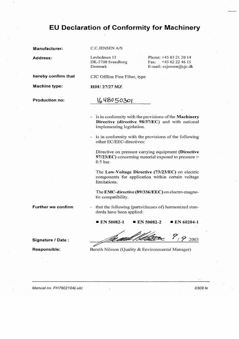
EU Declaration of Conformity for Machinery
Manufacturer:
Address:
hereby confirm that
Machine type:
C.C.JENSEN A/S
Lervholmen 13DK-5700 SvendborgDenmark
CJC Offline Fine Filter, type
HDU 27/27 MZ
Phone:+45 63 21 20 14Fax: +45 62 22 46 15E-mail: [email protected]
Production no: Xlo^oso i
Further w e confirm
is in conformity with the prov isions of the MachineryDirective (directive 98/37/EC) and with nationalimplementing legislation.
is in conformity with the provisions of the followingother EC /EEC-directives:
Directive on pressure carrying e quipme nt (Directive97/23/EC) concerning material exposed to pressure >0.5 bar.
The Low-Voltage Directive (73/23/EC) on electriccomponents for application within certain voltagelimitations.
The EMC-directive (89/336/EEC ) on electro-magnetic compatibility.
that the following (parts/clauses of) harmonized standards have been applied:
EN 50082-1 EN 50082-2 EN 60204-1
Signature / Date
Responsible:
/ P 2003
Bernth Nilsson (Quality & Environmental Manage r)