documentcl
DESCRIPTION
CLTRANSCRIPT

CL-1
CLUTCH
C TRANSMISSION/TRANSAXLE
CONTENTS
D
E
F
G
H
I
J
K
L
M
SECTIONCLA
B
CL
CLUTCH
PRECAUTIONS .......................................................... 2Service Notice or Precautions .................................. 2
PREPARATION ........................................................... 3Special Service Tools ............................................... 3Commercial Service Tools ........................................ 3
NOISE, VIBRATION AND HARSHNESS (NVH)TROUBLESHOOTING ................................................ 5
NVH Troubleshooting Chart ..................................... 5CLUTCH PEDAL ........................................................ 6
On-Vehicle Inspection and Adjustment .................... 6Removal and Installation .......................................... 7
COMPONENTS .................................................... 7REMOVAL ............................................................. 7INSPECTION AFTER REMOVAL ......................... 7INSTALLATION ..................................................... 7
CLUTCH FLUID .......................................................... 8Air Bleeding Procedure ............................................ 8
CLUTCH MASTER CYLINDER .................................. 9Components ............................................................. 9Removal and Installation .......................................... 9
REMOVAL ............................................................. 9INSTALLATION ..................................................... 9
Disassembly and Assembly ................................... 10DISASSEMBLY ................................................... 10INSPECTION AFTER DISASSEMBLY ............... 10ASSEMBLY ......................................................... 10
OPERATING CYLINDER ...........................................11Components ............................................................11Removal and Installation .........................................11
REMOVAL ........................................................... 11INSTALLATION ................................................... 12
Disassembly and Assembly .................................... 12DISASSEMBLY ................................................... 12INSPECTION AFTER DISASSEMBLY ................ 12ASSEMBLY ......................................................... 12
CLUTCH PIPING ....................................................... 13Removal and Installation ........................................ 13
CLUTCH RELEASE MECHANISM ........................... 14Removal and Installation ........................................ 14
COMPONENTS ................................................... 14REMOVAL ........................................................... 14INSPECTION AFTER REMOVAL ....................... 15INSTALLATION ................................................... 15
CLUTCHDISC,CLUTCHCOVERANDFLYWHEEL... 17Removal and Installation ........................................ 17
COMPONENTS ................................................... 17REMOVAL ........................................................... 17INSPECTION AND ADJUSTMENT AFTERREMOVAL ........................................................... 17INSTALLATION ................................................... 18
SERVICE DATA AND SPECIFICATIONS (SDS) ...... 20Clutch Control System ............................................ 20Clutch Master Cylinder ........................................... 20Clutch Operating Cylinder ...................................... 20Clutch Disc ............................................................. 20Clutch Cover ........................................................... 20Clutch Pedal ........................................................... 20
CL-2
PRECAUTIONS
PRECAUTIONS PFP:00001
Service Notice or Precautions ECS00ICC
● Recommended clutch fluid is brake fluid “DOT 3” or “DOT 4”. Refer to MA-14, "RECOMMENDED FLUIDSAND LUBRICANTS" .
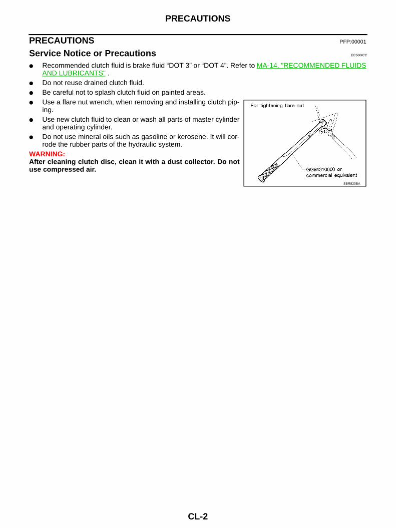
● Do not reuse drained clutch fluid.● Be careful not to splash clutch fluid on painted areas.● Use a flare nut wrench, when removing and installing clutch pip-
ing.● Use new clutch fluid to clean or wash all parts of master cylinder
and operating cylinder.● Do not use mineral oils such as gasoline or kerosene. It will cor-
rode the rubber parts of the hydraulic system.WARNING:After cleaning clutch disc, clean it with a dust collector. Do notuse compressed air.
SBR820BA
PREPARATION
CL-3
D
E
F
G
H
I
J
K
L
M
A
B
CL
PREPARATION PFP:00002
Special Service Tools ECS00ICD
Commercial Service Tools ECS00ICE
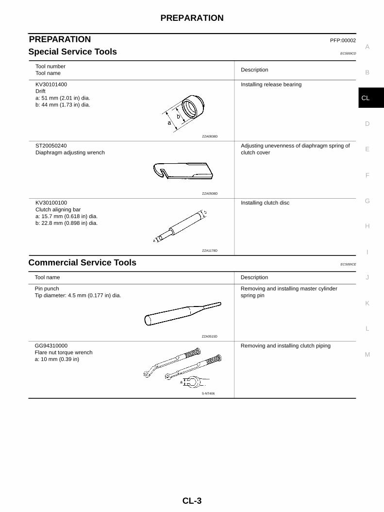
Tool numberTool name
Description
KV30101400Drifta: 51 mm (2.01 in) dia.b: 44 mm (1.73 in) dia.
Installing release bearing
ST20050240Diaphragm adjusting wrench
Adjusting unevenness of diaphragm spring ofclutch cover
KV30100100Clutch aligning bara: 15.7 mm (0.618 in) dia.b: 22.8 mm (0.898 in) dia.
Installing clutch disc
ZZA0838D
ZZA0508D
ZZA1178D
Tool name Description
Pin punchTip diameter: 4.5 mm (0.177 in) dia.
Removing and installing master cylinderspring pin
GG94310000Flare nut torque wrencha: 10 mm (0.39 in)
Removing and installing clutch piping
ZZA0515D
S-NT406

CL-4
PREPARATION
Flare nut torque wrencha: 14 mm (0.55 in)
Removing and installing clutch piping (ForLHD models)
Puller Removing release bearing
Tool name Description
S-NT406
NT077

NOISE, VIBRATION AND HARSHNESS (NVH) TROUBLESHOOTING
CL-5
D
E
F
G
H
I
J
K
L
M
A
B
CL
NOISE, VIBRATION AND HARSHNESS (NVH) TROUBLESHOOTING PFP:00003
NVH Troubleshooting Chart ECS00ICF
Use the chart below to help you find the cause of the symptom. The numbers indicate the order of the inspec-tion. If necessary, repair or replace these parts.
Reference page
CL-
6
CL-
8
CL-
9
CL-
11
EM
-106
CL-
14
CL-
17
EM
-134
SUSPECTED PARTS (Possible cause)
CLU
TC
HP
ED
AL
(Ins
pect
ion
and
adju
stm
ent)
CLU
TC
HLI
NE
(Air
inlin
e)
MA
ST
ER
CY
LIN
DE
RP
IST
ON
CU
P(D
amag
ed)
OP
ER
AT
ING
CY
LIN
DE
RP
IST
ON
CU
P(D
amag
ed)
EN
GIN
EM
OU
NT
ING
(Loo
se)
RE
LEA
SE
BE
AR
ING
(Wor
n,di
rty
orda
mag
ed)
CLU
TC
HD
ISC
(Out
oftr
ue)
CLU
TC
HD
ISC
(Run
outi
sex
cess
ive)
CLU
TC
HD
ISC
(Lin
ing
brok
en)
CLU
TC
HD
ISC
(Dirt
yor
burn
ed)
CLU
TC
HD
ISC
(Oily
)
CLU
TC
HD
ISC
(Wor
nou
t)
CLU
TC
HD
ISC
(Har
dene
d)
CLU
TC
HD
ISC
(Lac
kof
splin
egr
ease
)
DIA
PH
RA
GM
SP
RIN
G(D
amag
ed)
DIA
PH
RA
GM
SP
RIN
G(O
utof
tipal
ignm
ent)
PR
ES
SU
RE
PLA
TE
(Dis
tort
ion)
FLY
WH
EE
L(D
isto
rtio
n)
Symptom
Clutch grabs/chatters 1 2 2 2 2 2
Clutch pedal spongy 1 2 2
Clutch noisy 1
Clutch slips 1 2 2 3 4 5
Clutch does not disengage 1 2 3 4 5 5 5 5 5 5 6 6 7

CL-6
CLUTCH PEDAL
CLUTCH PEDAL PFP:46540
On-Vehicle Inspection and Adjustment ECS00ICG
1. Make sure that clevis pin floats freely in the bore of clutch pedal.It should not be bound by clevis or clutch pedal.
a. If clevis pin is not free, make sure that pedal stopper bolt orASCD clutch switch is not applying pressure to clutch pedalcausing clevis pin to bind. To adjust, loosen lock nut and turnpedal stopper bolt or ASCD clutch switch.
b. Tighten lock nut.c. Make sure that clevis pin floats in the bore of clutch pedal. It
should not be bound by clutch pedal.d. If clevis pin is still not free, remove clevis pin and check for
deformation or damage. Replace clevis pin if necessary. Leavethe pin removed for step 2.
2. Check clutch pedal stroke for free range of movement.a. With clevis pin removed, manually move clutch pedal up and down to determine if it moves freely.b. If any sticking is found, replace related parts (clutch pedal bracket, assist spring, bushing etc.) Re-assem-
ble clutch pedal and again make sure that clevis pin floats freely in the bore of clutch pedal.3. Adjust clearance “C” while depressing clutch pedal fully. (With
clutch interlock switch)
4. Check clutch hydraulic and system components (clutch mastercylinder, clutch operating cylinder, clutch withdrawal lever, clutchrelease bearing, etc.) for sticking or binding.
a. If any sticking or binding is found, repair or replace related partsas necessary.
b. If hydraulic system repair was necessary, bleed the clutchhydraulic system. Refer to CL-8, "Air Bleeding Procedure" .NOTE:Do not use a vacuum assist or any other type of power bleederon this system. Use of a vacuum assist or power bleeder will notpurge all the air from the system.
Clearance “C” : 0.1 - 1.0 mm (0.004 - 0.039 in)
PCIB0907E
SCL800

CLUTCH PEDAL
CL-7
D
E
F
G
H
I
J
K
L
M
A
B
CL
Removal and Installation ECS00ICH
COMPONENTS
REMOVAL1. Disconnect clutch interlock switch and ASCD clutch switch (with ASCD) harness connectors.2. Remove snap pin and clevis pin from clevis of clutch master cylinder.3. Remove clutch pedal assembly mounting nuts and bolt, and then remove clutch pedal assembly from the
vehicle.
INSPECTION AFTER REMOVAL● Check clutch pedal for bend, damage, or a cracked weld. If bend, damage, or a cracked weld is found,
replace clutch pedal.● Check assist spring for settling. If settling is found, replace assist spring.
INSTALLATIONInstallation is the reverse order of removal.NOTE:Tighten pedal stopper bolt lock nut or ASCD clutch switch lock nut to the specified torque after installing clutchpedal assembly in vehicle and adjusting the pedal free play.
1. Clutch pedal assembly 2. Clevis pin 3. Bushing
4. Stopper rubber 5. Pedal stopper bolt (Without ASCD) 6. ASCD clutch switch (With ASCD)
7. Pedal pad 8. Stopper rubber 9. Snap pin
10. Clutch interlock switch 11. Bushing 12. Assist spring
PCIB1387E
CL-8
CLUTCH FLUID
CLUTCH FLUID PFP:00017
Air Bleeding Procedure ECS00ICI
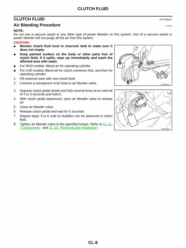
NOTE:Do not use a vacuum assist or any other type of power bleeder on this system. Use of a vacuum assist orpower bleeder will not purge all the air from the system.CAUTION:● Monitor clutch fluid level in reservoir tank to make sure it
does not empty.● Keep painted surface on the body or other parts free of
clutch fluid. If it spills, wipe up immediately and wash theaffected area with water.
● For RHD models: Bleed air for operating cylinder.● For LHD models: Bleed air for clutch connector first, and then for
operating cylinder.1. Fill reservoir tank with new clutch fluid.2. Connect a transparent vinyl hose to air bleeder valve.
3. Depress clutch pedal slowly and fully several times at an intervalof 2 to 3 seconds and hold it.
4. With clutch pedal depressed, open air bleeder valve to releaseair.
5. Close air bleeder valve.6. Release clutch pedal and wait for 5 seconds.7. Repeat steps 3 to 6 until no bubbles can be observed in clutch
fluid.8. Tighten air bleeder valve to the specified torque. Refer to CL-11,
"Components" and CL-13, "Removal and Installation" .
PCIB1601E
PCIB1390E
CLUTCH MASTER CYLINDER
CL-9
D
E
F
G
H
I
J
K
L
M
A
B
CL
CLUTCH MASTER CYLINDER PFP:30610
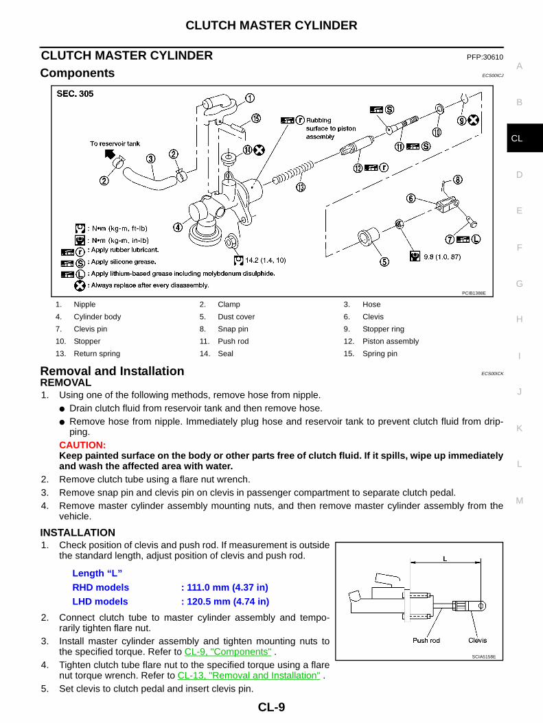
Components ECS00ICJ
Removal and Installation ECS00ICK
REMOVAL1. Using one of the following methods, remove hose from nipple.
● Drain clutch fluid from reservoir tank and then remove hose.● Remove hose from nipple. Immediately plug hose and reservoir tank to prevent clutch fluid from drip-
ping.CAUTION:Keep painted surface on the body or other parts free of clutch fluid. If it spills, wipe up immediatelyand wash the affected area with water.
2. Remove clutch tube using a flare nut wrench.3. Remove snap pin and clevis pin on clevis in passenger compartment to separate clutch pedal.4. Remove master cylinder assembly mounting nuts, and then remove master cylinder assembly from the
vehicle.
INSTALLATION1. Check position of clevis and push rod. If measurement is outside
the standard length, adjust position of clevis and push rod.
2. Connect clutch tube to master cylinder assembly and tempo-rarily tighten flare nut.
3. Install master cylinder assembly and tighten mounting nuts tothe specified torque. Refer to CL-9, "Components" .
4. Tighten clutch tube flare nut to the specified torque using a flarenut torque wrench. Refer to CL-13, "Removal and Installation" .
5. Set clevis to clutch pedal and insert clevis pin.
1. Nipple 2. Clamp 3. Hose
4. Cylinder body 5. Dust cover 6. Clevis
7. Clevis pin 8. Snap pin 9. Stopper ring
10. Stopper 11. Push rod 12. Piston assembly
13. Return spring 14. Seal 15. Spring pin
PCIB1388E
Length “L”RHD models : 111.0 mm (4.37 in)LHD models : 120.5 mm (4.74 in)
SCIA5158E

CL-10
CLUTCH MASTER CYLINDER
6. Attach snap pin to clevis pin.7. Install hose to nipple.8. After completing this procedure, inspect and adjust for clutch pedal and then bleed the air from the clutch
hydraulic system. Refer to CL-6, "On-Vehicle Inspection and Adjustment" and CL-8, "Air Bleeding Proce-dure" .
Disassembly and Assembly ECS00ICL
DISASSEMBLY1. Remove spring pin using a pin punch.2. Remove nipple and seal from cylinder body.3. Loosen push rod lock nut then remove clevis and lock nut, if
necessary.NOTE:Clutch pedal height is controlled with position of clevis and pushrod.
4. Remove dust cover from cylinder body.5. Remove stopper ring and stopper. Remove push rod from cylin-
der body while holding it securely to prevent piston assemblypopping out.
6. Remove piston assembly and return spring.
INSPECTION AFTER DISASSEMBLYCheck for any of the conditions shown below. If any malfunction is found, replace the part concerned.● Damaged cylinder internal wall, foreign matter, wear, corrosion, or pinhole● Damaged or deformed nipple or reservoir tank● Settling of return spring● Cracked or deformed dust cover
ASSEMBLY1. Apply rubber lubricant to the internal surface of cylinder body, the sliding surface of piston assembly, and
piston cup. Insert return spring and piston assembly to cylinder body.2. Apply silicon grease to push rod and install stopper. Install stopper ring while holding down push rod by
hand to prevent piston assembly from popping out.3. Install dust cover to cylinder body.4. Install seal and nipple to cylinder body.5. Install spring pin using a pin punch.6. Install clevis to push rod.7. Check and adjust the positions of clevis and push rod. After
adjusting “L”, tighten lock nut to the specified torque. Refer toCL-9, "Components" .
PCIB0274E
Length “L”RHD models : 111.0 mm (4.37 in)LHD models : 120.5 mm (4.74 in)
SCIA5158E
OPERATING CYLINDER
CL-11
D
E
F
G
H
I
J
K
L
M
A
B
CL
OPERATING CYLINDER PFP:30620
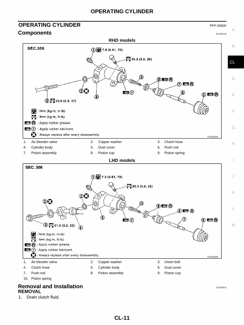
Components ECS00ICM
RHD models
LHD models
Removal and Installation ECS00ICN
REMOVAL1. Drain clutch fluid.
PCIB1602E
1. Air bleeder valve 2. Copper washer 3. Clutch hose
4. Cylinder body 5. Dust cover 6. Push rod
7. Piston assembly 8. Piston cup 9. Piston spring
PCIB1606E
1. Air bleeder valve 2. Copper washer 3. Union bolt
4. Clutch hose 5. Cylinder body 6. Dust cover
7. Push rod 8. Piston assembly 9. Piston cup
10. Piston spring

CL-12
OPERATING CYLINDER
CAUTION:Keep painted surface on the body or other parts free of clutch fluid. If it spills, wipe up immediatelyand wash the affected area with water.
2. Remove clutch hose from operating cylinder assembly.3. Remove operating cylinder assembly mounting bolts, and then remove operating cylinder assembly from
the vehicle.
INSTALLATIONNote the following, and install in the reverse order of removal.● Install clutch hose with care so that it will not be bent or twisted.● Tighten clutch hose to the specified torque.
CAUTION:Do not reuse copper washer.
● After completing the procedure, bleed the air from the clutch hydraulic system. Refer to CL-8, "Air Bleed-ing Procedure" .
Disassembly and Assembly ECS00ICO
DISASSEMBLY● Remove dust cover and push rod. Then remove piston, piston cup and piston spring from cylinder body.
INSPECTION AFTER DISASSEMBLYCheck for any of the conditions shown below. If any malfunction is found, replace the part concerned.● Damage to cylinder internal surface or piston sliding surface. Foreign matter, wear, corrosion, or pinhole● Settling of piston spring● Cracked or deformed dust cover
ASSEMBLY1. Apply rubber lubricant to cylinder body internal surface and rubber grease to piston cup and piston. Insert
piston assembly and piston spring into cylinder body.2. Apply rubber grease to dust cover and then install push rod and dust cover.

CLUTCH PIPING
CL-13
D
E
F
G
H
I
J
K
L
M
A
B
CL
CLUTCH PIPING PFP:30650
Removal and Installation ECS00ICP
RHD models
LHD models
Carefully observe the following steps during clutch tube removal and installation.CAUTION:Keep painted surface on the body or other parts free of clutch fluid. If it spills, wipe up immediatelyand wash the affected area with water.● To fix clutch hose on bracket, position clutch hose clasp on the
emboss of bracket and drive lock plate vertically from above. Becareful not to bend or twist clutch hose. Do not scratch or dam-age clutch hose.
● Tighten clutch tube flare nut to the specified torque.● Tighten clutch hose or union bolt to the specified torque.
CAUTION:Do not reuse copper washer.
● After installation, bleed the air from the clutch hydraulic system.Refer to CL-8, "Air Bleeding Procedure" .
PCIB1651E
1. Clutch tube 2. Clutch orifice 3. Lock plate
4. Clutch hose 5. Operating cylinder 6. Master cylinder
7. Clutch pedal
PCIB1605E
1. Clutch tube 2. Clutch orifice 3. Lock plate
4. Clutch hose 5. Operating cylinder 6. Clutch tube
7. Clutch connector 8. Air bleeder valve 9. Master cylinder
10. Clutch pedal
PCIB0681E
CL-14
CLUTCH RELEASE MECHANISM
CLUTCH RELEASE MECHANISM PFP:30502
Removal and Installation ECS00ICQ
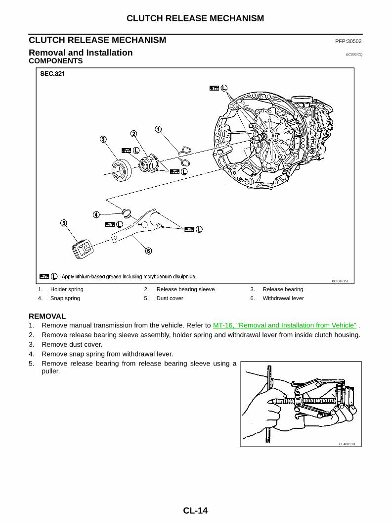
COMPONENTS
REMOVAL1. Remove manual transmission from the vehicle. Refer to MT-16, "Removal and Installation from Vehicle" .2. Remove release bearing sleeve assembly, holder spring and withdrawal lever from inside clutch housing.3. Remove dust cover.4. Remove snap spring from withdrawal lever.5. Remove release bearing from release bearing sleeve using a
puller.
1. Holder spring 2. Release bearing sleeve 3. Release bearing
4. Snap spring 5. Dust cover 6. Withdrawal lever
PCIB1615E
CLA0013D

CLUTCH RELEASE MECHANISM
CL-15
D
E
F
G
H
I
J
K
L
M
A
B
CL
INSPECTION AFTER REMOVAL● If release bearing is seized, damaged, not properly centered or
does not rotate smoothly, replace it.● If contact surface of withdrawal lever is excessively worn,
replace it.● If dust cover is cracked, replace it.
INSTALLATIONCAUTION:● Be sure to apply grease to the points specified. Otherwise, noise, poor disengagement, or damage
to the clutch may result. Excessive grease may cause slip or judder. Wipe off any grease oozingfrom the parts.
● Be careful not to bring any grease to the clutch disk facing, pressure plate surface and flywheelsurface.
1. Install release bearing to release bearing sleeve using the drift.
CAUTION:Press bearing inner race by pushing with the drift.
2. Following the instructions below, apply grease to the specified points.
CAUTION:Wipe off any old grease, debris, or powdery residue left on the grease applying surfaces.● Evenly apply approximately 1 mm (0.04 in) thick coating of recommended grease to withdrawal lever
and release bearing sliding surface.● Apply recommended grease to withdrawal lever ball pin contact surface and inner slots of release bear-
ing sleeve. The grease surface should be level with the surrounding area.● Apply a thin coat of recommended grease evenly to release bearing sleeve sliding surface of front
cover. Install release bearing sleeve assembly to front cover. Wipe off any excess grease that oozesfrom the parts and then remove release bearing sleeve assembly.
3. To install, reverse the removal procedure, following the cautions below.CAUTION:● Before installing manual transmission to the vehicle, make sure that each sliding surface slides
smoothly by operating withdrawal lever.
SCIA1660E
Tool number : KV30101400
PCIB0275E
PCIB1393E

CL-16
CLUTCH RELEASE MECHANISM
● When assembling, make sure that both ends of snapspring touch the end face of withdrawal lever.
● Be careful with the orientation snap spring.
SCIA6903E

CLUTCH DISC, CLUTCH COVER AND FLYWHEEL
CL-17
D
E
F
G
H
I
J
K
L
M
A
B
CL
CLUTCH DISC, CLUTCH COVER AND FLYWHEEL PFP:30100
Removal and Installation ECS00ICR
COMPONENTS
CAUTION:● Be careful not to bring any grease to the clutch disc facing, pressure plate surface and flywheel
surface.● If the flywheel is removed, align the dowel pin with smallest hole of flywheel. Refer to EM-114,
"ASSEMBLY " .
REMOVAL1. Remove manual transmission from the vehicle. Refer to MT-16, "Removal and Installation from Vehicle" .2. Loosen clutch cover mounting bolts evenly. Then remove clutch cover and clutch disc.
INSPECTION AND ADJUSTMENT AFTER REMOVALClutch Disc● Measure circumferential runout relative to clutch disc center
spline. If it is outside the specification, replace clutch disc.
● Measure backlash to clutch disc spline and main drive gearspline at the circumference of clutch disc. If outside the specifi-cation, replace clutch disc.
1. Flywheel 2. Clutch disc 3. Clutch cover
PCIB1394E
Runout limit/diameter of the area to be measured: 1.0 mm (0.039 in)/230 mm (9.06 in) dia.
Maximum allowable spline backlash
: 1.0 mm (0.039 in) SCL221

CL-18
CLUTCH DISC, CLUTCH COVER AND FLYWHEEL
● Measure the depth to clutch disc facing rivet heads using a cali-pers. If it exceeds the allowable wear limit, replace clutch disc.
Clutch CoverCheck diaphragm spring lever claws for unevenness with the leverstill on the vehicle. If they exceed the tolerance, adjust lever heightusing the diaphragm adjusting wrench.
● Check clutch cover thrust ring for wear or breakage. If wear orbreakage is found, replace clutch cover assembly.NOTE:● Worn thrust ring will generate a beating noise when tapped at
the rivet with a hammer.● Broken thrust ring will make a clinking sound when cover is shaken up and down.
● If a trace of burn or discoloration is found on the clutch cover pressure plate to clutch disc contact surface,repair the surface with sandpaper. If surface is damaged or distorted, replace the assembly.
Flywheel RunoutMeasure the runout at the flywheel clutch contact surface using adial indicator. If runout is outside the specification, replace flywheel.If a trace of burn or discoloration is found on the surface, repair itwith sandpaper.
CAUTION:Measure it at flywheel outer face (not on knock pin and clutchcover mounting hole).
INSTALLATION1. Apply recommended grease to clutch disc and main drive gear splines.
CAUTION:Be sure to apply grease to the points specified. Otherwise, noise, poor disengagement, or damageto the clutch may result. Excessive grease may cause slip or judder. Wipe off any grease oozingfrom the parts.
Facing wear limit (depth to the rivet head): 0.3 mm (0.012 in)
SCL229
Tolerance for diaphragm spring lever unevenness: 0.7 mm (0.028 in) or less
Tool number : ST20050240
PCIB0276E
Allowable flywheel runout: Refer to EM-134, "FLYWHEEL DEFLECTION " .
PBIC2646E
CLUTCH DISC, CLUTCH COVER AND FLYWHEEL
CL-19
D
E
F
G
H
I
J
K
L
M
A
B
CL
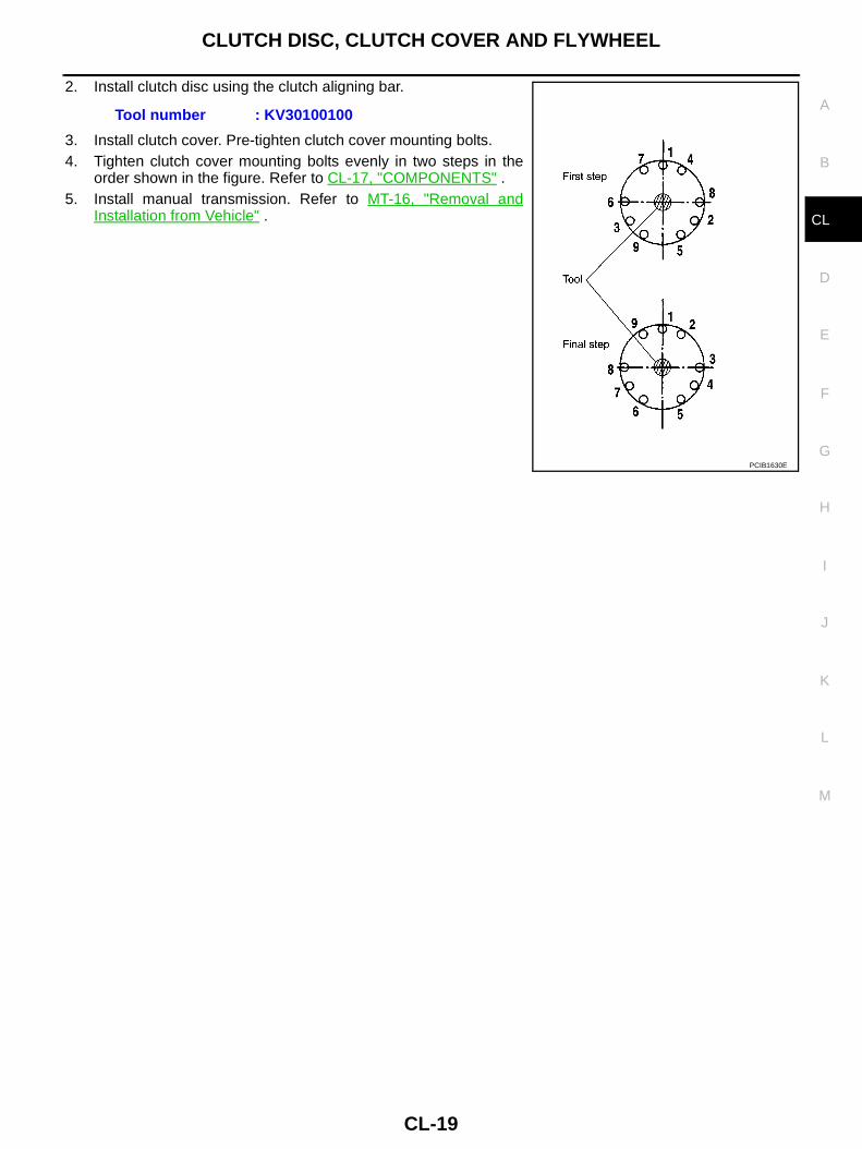
2. Install clutch disc using the clutch aligning bar.
3. Install clutch cover. Pre-tighten clutch cover mounting bolts.4. Tighten clutch cover mounting bolts evenly in two steps in the
order shown in the figure. Refer to CL-17, "COMPONENTS" .5. Install manual transmission. Refer to MT-16, "Removal and
Installation from Vehicle" .
Tool number : KV30100100
PCIB1630E

CL-20
SERVICE DATA AND SPECIFICATIONS (SDS)
SERVICE DATA AND SPECIFICATIONS (SDS) PFP:00030
Clutch Control System ECS00ICS
Clutch Master Cylinder ECS00ICT
Clutch Operating Cylinder ECS00ICU
Clutch Disc ECS00ICV
Clutch Cover ECS00ICW
Clutch Pedal ECS00ICX
Type of clutch control Hydraulic
Inner diameter 15.87 mm (5/8 in)
Inner diameter 19.05 mm (3/4 in)
Facing size (outer dia. x inner dia. x thickness) 240 mm × 160 mm × 3.15 mm (9.45 in × 6.30 in × 0.1240 in)
Wear limit of facing surface to rivet head 0.3 mm (0.012 in)
Runout limit/diameter of the area to be measured 1.0 mm (0.039 in) / 230 mm (9.06 in) dia.
Maximum spline backlash (at outer edge of disc) 1.0 mm (0.039 in)
Set-load 9,810 N (1,000 kg, 2,205 lb)
Diaphragm spring lever height 39.0 - 41.0 mm (1.535 - 1.614 in)
Uneven limit diaphragm spring toe height 0.7 mm (0.028 in) or less
Clearance ″C″ between pedal stopper rubber and clutch interlockswitch threaded while clutch pedal is fully depressed
0.1 - 1.0 mm (0.004 - 0.039 in)