clamping devices for drills and millers (summary)
TRANSCRIPT

Clamping Devices for Drills and Millers
(Summary)
II
r- ---
1
---r----I ---,
. Collet attachment 1
3-Jaw drill chuck (not the same as Arbor ' I I I I I I
with the lathe)
.···:_· ..
: • ·�
@ --
--
, ----
; ------- I
1- ------I
Spiral drill I
Centering drill Millers and fly cutter Countersunk
46
MIiiers with 16 mm,bore
@.

Machine vice
Clamping Devices for Workpieces (Summary)
MIiiing table 3-Jaw chuck 4-jawIndependent chuck
Collet attachment
Clamping plate 90 mm dia.

Clamping Devices for Drills and Millers
3-Jaw Drill Chuck
Clamping capacity: 1 - 6 mm The 3-jaw drill chuck is identical with that used with the lathe. It is mounted directly onto the main spindle.
Collet Attachment
•. .
Clamping capacity using the collets ESX
25: 1,5 - 14 mm
I'he collet attachment for the vertical \mi t has an M14 x 1 mounting· thr�ad and is therefore not identical with that for the lathe. The collets for the ver·ical unit and the lathe are the same.
'lillers must be clamped securely and
1•i th highest round-run accuracy. Forthis reason, the collet attachment is 1ecessary. Clamping is accomplished y means of the pins which are inclued.
.. .,,.._:
:-·.w col let: attachments being usec.
48
Tighten clamping nut (1) clockwise! Note: if you look at the clamping nut from the top, the tightening direction, however, looks counterclockwise.
When working with the fly cutter (dia. of shaft 8 mm) secure clampi�g of the shaft is absolutely necessary.
Arbor
I
I
The arbor serves for clamping tl;le gear mills, the circular saw blade a;a other millers with a center bore of 16 mm •

Clamping Devices for Workpieces
The Machine Vice
Technical data
Width of clamping jaws: 46 mm Height of clamping jaws: 18 mm Opening of jaws_: up to 32 mm
Mounting on cross slide
1. Remove set screw (1)
2. Mount machine vice on cross slideand tighten with the two shortersocket head screws M6 x 20.
49
Mounting on milling table
Mount the machine vice on the milling table with the two longer socket head screws M6 x 16 and the T-nuts. The machine vice can be mounted on the milling table lcngitudinally or crosswise.
Working tip
:;:: The v-recess in the machine vice ) serves for vertically clamping :::; round workpieces.

The Milling Table
Dimensions:
Length x width: 120 x So mm Max. clamping height with short -screws: up to 15 mm Max. clamping height with long screws: up to 35 mm
Mounting on the cross slide:
The mil\ing table can be mounted in longitudinal or cross direction on the cross slide with the socket head scr�ws M6 X 12.
·· If you want to adjust the clampingof the milling table exactly parallel to the lathe bed, feed a roundpin in the collet and align thetable.
Adjust the hexagon screw so that the clamping shoe is vertical.
so
The Support Flange
The support flange has the same dimensions as the spindle nose of the lathe spindle. Mount the support flange on the cross slide with the socket head screw M6 x 12.
Following devices can be mounted on the
support flange: 3-jaw chuck, collet
attachment for lathe, clamping plate,
4-jaw independent chuck.
�oce that all contact surfaces are clean - cross slide-support flange,
... support flange-3-jaw chuck.
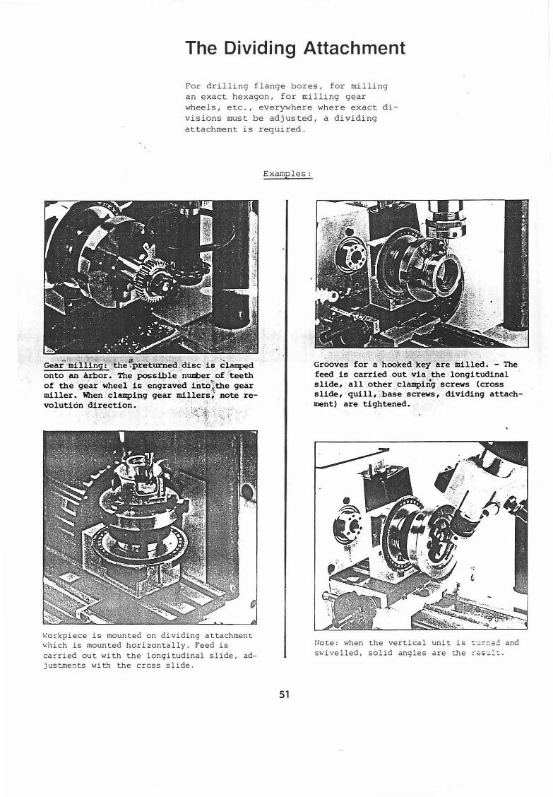
The Dividing Attachment
For drilling flange bores, for milling
an exact hexagon, for milling gear
wheels, etc., everywhere where exact di
visions must be adjusted, a dividing
attachment is required.
Gear· milling: the ·:preb1med. disc is-�lamped onto an arbor. The possible muxt>er of. -teeth of the gear wheel is engraved into';,the gear miller. When clamping gear millers; n.ote revolution direction.
Workpiece is mounted on dividing attachment
which is mounted horizontally. Feed is
carried out with the longitudinal slide, ad
justments with the cress slide.
Examples:
51
Grooves for a·hooked key are milled. - The feed is carried out via the longitudinal slide, all other clamping.screws (cross slide, -'quill, base screws, dividing attachment) are tightened.
Note: when the vertical unit is cc:::-:-.ec and
s1s•ivelled, solid angles are the ::-esc:lt:.

3-jaw chuck
Clamping Devices for the Dividing Attachment (Summary) (identical with Clamping Devices for Turning)
4-jaw independent chuck Collet attachment
52
Clamping plate 90 mm dia.

Mounting the dividing attachment
Vertical mounting: During milling operations, :eed should be achievec via the longitucinal or cross slide. For this reason, the dividing attachment can be mounted either horizontally or vertically.
Mount dividing attachment on the cross slide with the two socket head screws M6 x 4o.
Horizontal mounting:
Mount the dividing attachment on the cross slide with the two hexagon screws M6 X 16.
Circle Dividing
of holes
I G::= '
! -
56 2 ! .,
48
i I
2 3 i ,; I
2 I i 36 3 .;
The dividing chart
The dividing chart indicates the dividing possibilities for the respective circle of holes.
Example:
15 divisions are required. These are reached with the circle of holes 60. 60:15 = 4. I.e., division in every fourth hole.
possibilities
I I I
I6-I I
I 7 i 8
I 6 8 I I
i i
6I
i 9 1
I
53
. - I 12
12
12
I I I
!
I I
I 1½
!
I
I
. .,
I I " : I
J::, C'.: - -I
I
I 28 -�
I :)O
I 16 24 46
;
: 1 -.t; 36
I

Dividing procedure
�1. Insert index bolt (1) into bore for
required division. The outermost
circle of divisions has 60 holes,
the second has 56, etc.
2. P.un the index bolt 'and turr di vi ding plate as many divisions as re·quired.
54
3. Tighten clamping screw (2) before
each milling or drilling operation!
Working_tie:
:�; ::ll'l'lrl
. --�--;' - - .
Mark the graduation �ith a felt marker for better ori�tation. Example� ·1s d:i.visions are required. 36o0· : 15 =-24°·. Mark 240, 48° ·, etc.

Wiring Diagram for Lathe
A 12.819
r·--·
I
L---·
R
, I
! I
·-·-·-·-·.J
,--·-·-·-· -·-·1
i r---------, i . Z2.
St
I
I
i i I
I
I "'' I I
. . I I
•
! @-i-·-·-·_J L,--·-· . _______ ;
b1 Main switch
kl Condensor
ml Motor
Connection Scheme
for Main Switch
b1 1 3 5
' 6 vorw. - " "
- - - -
0 - -- - - -
:Cackw. )( - -
55
7 8 -
-
-
X
Wiring Diagram for Milling and Drilling Unit
t 1 s64
ZI k1
m1
u, U1
9 11 10 12
)( "
-
-)( X

·SERVICETEILE
SERVICE PARTS
. .
PIECES DE SERVICE

2------�<
3---------�
5
�
14
6
7
1J1s
8
1 Pos Ref. No. DIN,:
BENENNUNG DESCRIPTION DESIGNATION
Grundausstattung Basic equipment Equiptment de base
1 A5A 000 310 Orehstahlunterlage 0,2 Tool base 0,2 Base pour outil 0,2
2 A5A 000 320 Orehstahlunterlage 0,5 Tool base 0,5 Base pour outil 0,5
3 ASA 000 330 Orehstahlunterlage 1,0 Tool base 1,0 Base pour ,til 1,0
ASA 070000 Drehherzsc:hutz Guard for lathe dog Protecteur pour toe de tour6 ZSR 12 0508 MSx8 OIN912·6.9 Zyl indersch raube Socket head screw Vis 6 pans creux
,1 ASA 000 260 Kornerspitze MK 1 Lathe center MT1 Contre-pointe CM 1•;
8 B2A 000 420 Kornerspitze MK2 Lathe center MT2 Contre-pointe CM2iO zwz 94 0800 sw8 DIN 894 Seinmaulschli.issel Single-ended spanner Cle deservi�
111 B2A 000 470 R ing-Maulsch!ussel Key Cle a oeil t 12 zwz 11 0500 SWS DIN 911 Schraubendreher Hexagonal key Cle a six pans13 zwz 11 0400 SW4 DIN 911 Sch rau bendreher Hexagonal key Cle a six pans14 ASA 000 350 SW3 Stihschlussel Hexagonal key Cle a six pans15 A2A 080 000 Drehherz Lathe dog Toe de tour16 ZSR 84 0525 M5x25 DIN 84 Zyl inderschraube Flat head screw Vis a tete cylindrique
2

�- Ref. No.
1 ASA 010 010 2 ASA 010 020 3 ASA 010 030 4 AJA 000 040 5 ZSA 12 0845 6 ZRG 28 0000 7 ZSR 12 0630 8 ZSR 12 0625 9 ZMU 34 0600
I I I I.
2 3
I
I
I _.,1
: Yqp,�•---------6
.- ... J-Q,____.. -5
DIN BENENNUNG
Sett
Bett Soindelstock Reitstock Klemmplatte
M8x450IN912-6.9 Zylindetschraube BS DIN 127 Federring M6x300IN912-6.9 Zylinderschraube
M6x25DIN912·6.9 Zylinderschraube
. M6 DIN 934-6 Sechskantmu tter
3
8
V--7
I I I
�4
DESCRIPTION O!SIGNATION
Bed Banc
·:
Banc .�Bed
Headstock Poupfe fixe
Tail stock t:: . Corps de la pou;Je-:
Clampirg pJ�-� Plaque de blocage
Socket heac :.:.•f:w Vis 6 pans creux
Spring washP.' Rondelle - ressort
Socket heac :,:.-·e"" Vis 6 pans creux
Socket heac :,: . -:-.�,J Vis 6 pans creux
Hexagonal�--· Ecrou 6 pans

ros Ref. No. DIN BENENNUNG DESCRIPTION DESIGNATION
1 ASA 000 060 Raderdeckel Cover Couvercle 2 ZSR 12 0616 M6x1601N912·6.9 Zyl inderschraube Socket head screw Vis 6 pans creux 3 2S8 25 0640 86.4 DIN 125 Scheibe Washer Rondelle 4 ZAG 71 0607 6x0,7 DIN 471 Sicherungsring Retaining ring , - Anneau de retenues ASA 130 000 Tragerplatte Carrier plate Plaque s-:Jpport seule
ASA 060 000 Vorgelegeriemenscheibe Countershaft pulley Poulie7 ZSB 10 2181 SS/12x18x1 ,2 Sti:itzscheibe Supporting ring Rondelle 8 ZSB 99 0900 ( DIN 6799 Sicherungsscheibe Retaining washer Poul ie de retenue9 ASA 000 030 Motorriemenscheibe Motor pulley Paulie de moteur
10 ZSB 22 0530 B5,3 01 N 9021 Sch�ibe Washer Rondelle i 1 ZSR 84 0512 M5x12 OIN84-4.8 J Zylinderschraube Flat head screw Vis a tete cylindrique 12 ZSR 11 0512 M5x12 OIN6912-6.9 Zylinderschraube Flat head screw Vis a tete cylindrique13 ZSB 22 0530 85,3 DIN 9021 Scheibe Washer Rondelle14 ZMU 800800 NM8 DIN 980-8 Sicherungsmutter Securing nut Ecrou de surete16 ZSB 21 0840 A8,4 DIN 9021 Scheibe Washer Rondelle 16 ASA 000100 Lagerbolzen Bearing shaft Axe palier17 ZRG 71 2412 24x1,2 DIN 471 Sicherungsring Retaining ring Anneau de retenue1�: ASA 000020 Riemenscheibe Pulley Poulie
; .
19 ZLG.:600602 . 6006-22 RUlenkugellager Ball bearing Roulementibitles
20 ZSB -�·�02 6006,.: 6006/K2 Ausgf elchschelbe Compensating washer RondeHe d&_compensation21 ZSB 106553 SS45x55x3 Stiitzscheibe Supporting ri� Rondelle22 ZRG 726520 B55x2 DIN 472 Sk:herungsring Retaining ring Anneau de retenue23· MA. 000010 Hauptspindel Main splncle Broc:he prindpale-1 ZRM 406335 6x335 Keilriemen V-Belt Counoie trapfimidale
ZRM 406450 .. 6x450 Keilriemen V-Belt Counoie trapUl)ldale
6 ZSR 330612 M6x12 DIN93J.5,6 Sechskantsch reube Hexagon head screw Vis hexagonale 7 ASA 030000 Splndelstockabdeckung Headstock covermount T61e de cowerture
-ZMU 340800 M8 DIN 934-6 Sechskantmutter Hexagon nut Ecrou &pans9 ZSR 33 0625 M6x25 01 N933-5.6 Sechskantschraube Hexagon head screw Vis hexagonale0 ZMU 34 0600 MS DIN 934-6 Sechskantmutter Hexagon nut Ecrou 6 pans1 ZST 72 0312 3x12 DIN 1472-6.8 PaBkerbstift Grooved adjusting pin Goupille de position2 ASA 000 360 Frontschild SOHz metr. Front plate 50Hz. metr. Plaque frontale 50 Hz. metr.
ASB 000 360 Frontschild 60Hz zollig Front plate 60Hz. inch Plaque frontale 60 Hz. en poucelASD 000 360 Frontschild 50Hz zollig Front plate 50Hz. inch Plaque frolJPle 50Hz. en pouces ASC 000 360 Frontschild 60Hz metr. Front plate 60Hz. metr. Plaque f roilale 60Hz. metr.
3 3 ZOK 60 0019 Versch I uBstopfen Plug Bouchon filedi
4

17 18
5