clamping systems warranty - ceeindustrial
TRANSCRIPT

Clamping systems
The general terms and conditions of HEMA Maschinen-
und Apparateschutz GmbH apply; these can be viewed at
www.hema-schutz.de. The following additional points apply
to the clamping system range of products:
RotoClampDue to its construction, the tolerance range of the
RotoClamp (tolerance: cylindricity) between the shaft and
the clamp must be maintained within the defined range;
a deviation from this range may result in damage to the
housing or the diaphragm when in continuous operation.
A deviation from the tolerance range results in loss of the
warranty.
The warranty period for RotoClamp Inside Standard is
12 months from the date of delivery or at most 1,000,000
clamping cycles (no emergency or brake clamping). In
case of warranty, the customer must provide suitable
proof of the actual number of clampings.
The warranty period for RotoClamp Inside Active is
12 months from the date of delivery or at most 500,000
clamping cycles (no emergency or brake clamping). In
case of warranty, the customer must provide suitable
proof of the actual number of clampings.
LinClampThe LinClamp S clamping elements are designed for static
and dynamic clamping. LinClamp S safety clamping
systems have a warranty of 12 months from the date of
delivery, or at most 1,000,000 (S/SK)/ 100,000 (SA)
clampings (no emergency stop braking) or 500 emergency
stop brakings (brake only permissible with sinter linings;
if other linings are used then this warranty and the
features described do not apply). In case of warranty,
the customer must provide suitable proof of the actual
number of clampings.
The LinClamp A clamping elements are designed for sta-
tic functional clamping (no precision clamping). LinClamp
A safety clamping elements have a warranty of 12 months
after the date of delivery, but at most a clamping cycle of a
maximum of 10,000 clampings (no emergency stop braking).
In case of warranty, the customer must provide suitable
proof of the actual number of clampings.
The LinClamp S/SK/SA clamping elements are preset at
the factory to the respective rail dimensions. The contact
surfaces of the brake and clamping linings are pressed
onto the free surfaces of the respective linear guide rail.
The pressing procedure therefore does not influence the
accuracy and lifetime of the mounting rail.
PClampThe PClamp clamping elements are designed for sta-
tic clamping. PClamp safety clamping elements have a
warranty of 12 months after the date of delivery, but at
most a clamping cycle of a maximum of 1,000,000 clamp-
ings. In case of warranty, the customer must provide
suitable proof of the actual number of clampings.
The PClamp clamp elements are preset at the factory to
the respective rod length and cylinder size.
The clamping elements are NOT intended for securing loads.
Correct use of the clamping elements presupposes that these
are only used within the possibilities laid out and described
in the technical specifications. Other usages of the ele-
ments invalidate warranty.
Recommended operating temperature range for clamping
systems is between 10°C and 45°C, at pneumatic operating
pressure of 4 Bar or 6 Bar; medium: filtered compressed air
(40 μm), dry or oiled.
During assembly, reconstruction, maintenance and repairs,
the assembly instructions must be observed and the required
equipment and accessories must be used. During all work on
the clamping elements, the accident-prevention regulations as
well as the VDE safety and assembly instructions valid in
each case must be observed.
The operating and assembly instructions must be passed on
to the installation engineer, the operator and the user.
Warranty conditions for clamping systems
Warranty

Content
03
3
. . . . . . . . . . . . . . . . . . . . . . . . . . . . . . . . . . . . . . . . . . . . . . . . . . . . . . . . . . .Page
Product finder . . . . . . . . . . . . . . . . . . . . . . . . . . . . . . . . . . . . . . . . . . . . . . . .04
RotoClamp . . . . . . . . . . . . . . . . . . . . . . . . . . . . . . . . . . . . . . . . . . . . . . . . . . . .06
Advantages of the RotoClamp . . . . . . . . . . . . . . . . . . . . . . . . . . . . . . . . . . .07
Comparison of operating principles . . . . . . . . . . . . . . . . . . . . . . . . . . . . . . .08
Operating principle of the RotoClamp Inside . . . . . . . . . . . . . . . . . . . . . . .09
Operating principle of the RotoClamp Outside . . . . . . . . . . . . . . . . . . . . . .10
Technical data of the RotoClamp S . . . . . . . . . . . . . . . . . . . . . . . . . . . . . . . 11
Technical data of the RotoClamp N . . . . . . . . . . . . . . . . . . . . . . . . . . . . . . . 12
Technical data of the RotoClamp L . . . . . . . . . . . . . . . . . . . . . . . . . . . . . . . .13
Technical data of the RotoClamp YRT . . . . . . . . . . . . . . . . . . . . . . . . . . . . .14
Options/Installation . . . . . . . . . . . . . . . . . . . . . . . . . . . . . . . . . . . . . . . . . . . .15
Details of construction . . . . . . . . . . . . . . . . . . . . . . . . . . . . . . . . . . . . . . . . . .16
Request form . . . . . . . . . . . . . . . . . . . . . . . . . . . . . . . . . . . . . . . . . . . . . . . . . .17
Demonstration examples . . . . . . . . . . . . . . . . . . . . . . . . . . . . . . . . . . . . . . . .18
LinClamp . . . . . . . . . . . . . . . . . . . . . . . . . . . . . . . . . . . . . . . . . . . . . . . . . . . . .20
Advantages of the LinClamp . . . . . . . . . . . . . . . . . . . . . . . . . . . . . . . . . . . . .21
Operating principle . . . . . . . . . . . . . . . . . . . . . . . . . . . . . . . . . . . . . . . . . . . .22
Research results . . . . . . . . . . . . . . . . . . . . . . . . . . . . . . . . . . . . . . . . . . . . . . .24
Features of LinClamp . . . . . . . . . . . . . . . . . . . . . . . . . . . . . . . . . . . . . . . . . . .25
Technical data of LinClamp S /SK . . . . . . . . . . . . . . . . . . . . . . . . . . . . . . . .26
Technical data of LinClamp SA /A . . . . . . . . . . . . . . . . . . . . . . . . . . . . . . . .27
Recommendations/Installation/Warranty . . . . . . . . . . . . . . . . . . . . . . . . . . 28
Request form . . . . . . . . . . . . . . . . . . . . . . . . . . . . . . . . . . . . . . . . . . . . . . . . . .29
Demonstration examples . . . . . . . . . . . . . . . . . . . . . . . . . . . . . . . . . . . . . . . .30
PClamp . . . . . . . . . . . . . . . . . . . . . . . . . . . . . . . . . . . . . . . . . . . . . . . . . . . . . . .32
Advantages of the PClamp . . . . . . . . . . . . . . . . . . . . . . . . . . . . . . . . . . . . . .33
Operating principle . . . . . . . . . . . . . . . . . . . . . . . . . . . . . . . . . . . . . . . . . . . .34
Product overview . . . . . . . . . . . . . . . . . . . . . . . . . . . . . . . . . . . . . . . . . . . . . .35
Technical data of the PClamp N . . . . . . . . . . . . . . . . . . . . . . . . . . . . . . . . . .36
Technical data of the PClamp ISO . . . . . . . . . . . . . . . . . . . . . . . . . . . . . . . . 37
Technical data of the PClamp X /PClamp E . . . . . . . . . . . . . . . . . . . . . . . . .38
Request form . . . . . . . . . . . . . . . . . . . . . . . . . . . . . . . . . . . . . . . . . . . . . . . . . .39
Demonstration examples . . . . . . . . . . . . . . . . . . . . . . . . . . . . . . . . . . . . . . . .41
Quality at HEMA . . . . . . . . . . . . . . . . . . . . . . . . . . . . . . . . . . . . . . . . . . . . . . .42

Clamping systems
RotoClamp
RotoClamp
Inside
4 or 6 Bar
RotoClamp
Outside
4 or 6 Bar
Checklist of product selectionSelect the solution best suited to you from our wide range
of products. The HEMA clamping systems provide an in-
novative and above all fast and compact solution for the
most important applications. When making your selection,
please consider whether you want to actively clamp or
release using the applied compressed air based on the
model. The operating pressure you select decides on the
possible clamping force and is important when selecting
the model.
RotoClampRotoClamp is ideal for rotary position clamping in axes,
tables and swivel heads of machines. Two versions – Inside
and Outside – allow various directions of the clamping
function.
RotoClamp
Single/tandem version
RotoClamp
Single/tandem version
RotoClamp A
Clamping with air
RotoClamp
Single/tandem version
RotoClamp
Opening with air
RotoClamp
Single/tandem version
RotoClamp SA
RotoClamp NA
RotoClamp LA
RotoClamp YRTA
RotoClamp A
Clamping with air
RotoClamp
Opening with air
RotoClamp S
RotoClamp N
RotoClamp L
RotoClamp YRT

05
LinClamp
LinClamp
Opening with air
LinClamp
Surface or
rail clamping
PClamp
PClamp
4 or 6 Bar
LinClampFor single linear applications in which you do not want to
exclude emergency braking, the LinClamp systems with
sinter linings are recommended. Of course, you can also use
LinClamp for almost all types of linear guide system or
for processed surfaces for fast and safe clamping (steel
coverings).
PClampPClamp clamps and brakes rod loads safely and quickly. It
can be adapted to standard systems such as pneumatic
cylinders from leading manufacturers (e.g. SMC, Festo) or to
individual solutions. Rotary clamping can also be achieved
with PClamp. Certified systems from Employer’s Liability
Insurance Associations can be realised.
LinClamp
Clamping with air
LinClamp SA
Rail clamping
PClamp
with additional
safety device
PClamp X
in modular design
LinClamp
4 or 6 Bar
LinClamp A
Surface clamping
4 Bar
LinClamp S
Rail clamping
LinClamp SK
Compact rail
clamping
PClamp N
in modular design
PClamp ISO
in modular design
PClamp
without additional
safety device
PClamp E
Product finder

Clamping systems
RotoClamp
RotoClamp Inside
RotoClamp Outside

Advantages
07
Ro
to
Cla
mp
RotoClamp
1
2
3
4
5
6
7
Pneumatic clamping with high forces
Safety clamping RotoClamp Standard –
If the air supply fails then system clamps
The values of hydraulic clamping
are reached and exceeded
Low system costs in comparison
to hydraulics
Simple installation
Compact design
Suitable for all shaft sizes

Rotating
tabletop
Housing
Bearing
Clamping systems
Comparison of operating principles
Rotating
tabletop
Hydraulic clamping Pneumatic clamping
RotoClamp
Chamber with hydraulic oil
Housing
Bearing
Operating principle of hydraulic clamping
Function The chamber formed by the expansion ring and
the O-ring is supplied with hydraulic oil. The upper ring of
the expansion ring is pressed upwards and away elastically
and clamps the rotating brake disk between the fixed
expansion and counter rings. Standard table sizes with
500x500 mm pallets achieve approx. 3000 to 4000 Nm
holding torque at 80 to 120 Bar hydraulic pressure.
Safety No safety clamping. If there is a power loss then this
axis is no longer clamped.
Reaction times Long and short times with high effort can
be achieved.
Costs Precisely manufactured mechanical parts, expensive
hydraulic valves, hydraulic piping incl. assembly times,
assembly and matching of the mechanical parts; replaceable
in part. Safety clamping can only be realised at great effort.
Extra material costs of hydraulic vis-à-vis pneumatic.
(hydraulic valves, flexible hydraulic lines, piping and screwed
joints, relays due to higher rate of power consumption).
Cleanliness hydraulic.
Operating principle of the RotoClamp
Function Clamps with spring actuator. Depressurizing the
inner spring diaphragm chamber and ventilating the outer
spring diaphragm chamber relaxes the diaphragm and pres-
ses on the radial contact surfaces at the inner and outer
diameter of the spring. The clamping element is reformed
elastically in the area of the clamping surface and presses on
the shaft. Adding pressurized air to the inner spring
diaphragm chamber (4 or 6 Bar) and venting the outer spring
diaphragm chamber bends the diaphragm and the distance
between the two radial contact surfaces at the inner and
outer diameter of the spring is shortened: The clamping
surface lifts off from the shaft. You have the optional pos-
sibility of increasing the clamping force by extra loading of
the outer spring diaphragm chamber with compressed air
when clamped (4 or 6 Bar).
Safety Safety clamping by spring actuator. In case of a
power loss, the axis is immediately clamped.
Reaction times Very short due to pneumatics. With quick
air-vent valve and quick-acting gate valve attached directly
to the clamping mechanism, you can realise extremely short
clamping times.
Costs Low costs (in comparison to hydraulics), pneumatic
valves and pneumatic piping, low installation costs, no cost
for matching, easily replaceable, including safety clamp.
Cleanliness Very clean due to pneumatics.
Materials Clamping-body housing hardened and tempered
in fine grain mild steel, optional
supported flange joint hardened with case-hardening steel,
steel coated, alternative lining procedure possible.

Operating principle of the RotoClamp Inside
Funktion RotoClamp Inside
Release RotoClamp Inside Adding pressurized air to the
inner spring diaphragm chamber (open, 4 or 6 Bar) and
venting the outer spring diaphragm chamber (close) bends
the diaphragm and the distance between the two radial
contact surfaces at the inner and outer diameter of the
spring is shortened: The clamping element is opened in
this state.
Clamping RotoClamp Inside Depressurizing the inner
spring diaphragm chamber (open) and venting the outer
spring diaphragm chamber (close) relaxes the diaphragm
and presses on the radial contact surfaces at the inner and
outer diameter of the spring. The clamping element is re-
formed in the area of the clamping surface. The clamping
element is closed in this state.
RotoClamp Inside with secondary air You have the op-
tional possibility of increasing the clamping force by extra
loading of the outer spring diaphragm chamber (close) with
compressed air (4 or 6 Bar). The clamping element is closed
in this state.
Funktion RotoClamp Inside Aktiv
Release RotoClamp Inside The spring diaphragm is bent
on assembly and the distance between the two radial contact
surfaces at the inner and outer diameter of the spring is
reduced. The clamping element is opened in this state.
Clamping RotoClamp Inside Depressurizing the inner
spring diaphragm chamber (open) and venting the outer
spring diaphragm chamber (close, 4 or 6 Bar) reforms the
diaphragm and presses on the radial contact surfaces at the
inner and outer diameter of the spring. The clamping
element is reformed in the area of the clamping surface. The
clamping element is closed in this state.
Function of the RotoClamp Inside Active
09
Ro
to
Cla
mp
RotoClamp
RotoClamp standard inner clamping
Opening the spring actuator
RotoClamp standard inner clamping
Clamping optional with spring actuator and secondary air
Open
Open
Open
Open
Close
Close
Close
Close
p
p
p
p
p
A1= 1
A1= 0
A1= 0
A1 =1
A2= 0
A2= (1)
RotoClamp standard inner clamping active
opened
RotoClamp standard inner clamping active
Clamping with secondary air
Compressed air
Function of the RotoClamp Inside

Clamping systems
Operating principle of the RotoClamp Outside
Funktion RotoClamp Outside
Release RotoClamp Outside Adding pressurized air to the
inner spring diaphragm chamber (open, 4 or 6 Bar) and ven-
ting the outer spring diaphragm chamber (close) bends the
diaphragm and the distance between the two radial contact
surfaces at the inner and outer diameter of the spring is
shortened. The clamping element is opened in this state.
Release (open) RotoClamp Outside Depressurizing the
inner spring diaphragm chamber (open) and venting the
outer spring diaphragm chamber (close) relaxes the dia-
phragm and presses on the radial contact surfaces at the
inner and outer diameter of the spring. The clamping
element is reformed in the area of the clamping surface.
The clamping element is closed in this state.
Clamping RotoClamp Outside with secondary air You
have the possibility of increasing the clamping force by
extra loading of the outer spring diaphragm chamber (close)
with compressed air (4 or 6 Bar). The clamping element is
closed in this state.
Funktion RotoClamp Outside Aktiv
Release RotoClamp Outside The spring diaphragm is bent
on assembly and the distance between the two radial contact
surfaces at the inner and outer diameter of the spring is
reduced. The clamping element is opened in this state.
Clamping (close) RotoClamp Outside Depressurizing the
inner spring diaphragm chamber (open) and venting the
outer spring diaphragm chamber (close) with compressed
air (4 or 6 Bar) reforms the diaphragm and presses on the
radial contact surfaces at the inner and outer diameter of
the spring. The clamping element is reformed in the area
of the clamping surface. The clamping element is closed in
this state.
Open
Open
Close
Close
p
p
A1=1
A1= 0 A2= 0
A2= (1)
RotoClamp standard outer clamping
Opening the spring actuator
RotoClamp standard outer clamping
Clamping optional with spring actuator and secondary air
Open Close
pA1= 0
RotoClamp standard outer clamping active
opened
Open Close
pA1= 1
RotoClamp standard outer clamping active
Clamping with secondary air
Function of the RotoClamp Outside
Function of the RotoClamp Outside Active
Compressed air

Technical data
11
Ro
to
Cla
mp
RotoClampa
ø 5,5
t2
B
A
t1
B
A
In case of an alternative
connection, seal using
an M5 threaded screw0,02
Gravur
Air connection alternatively via
housing and o-ring seal, then
remove M5 threaded screw
Plananlage
Ra 0,8
D1
Ra
1,6
Air connection alternatively via
housing and o-ring seal, then
remove M5 threaded screw
In case of an alternative
connection, seal using
an M5 threaded plug
EF
M5
(ad
dit
ion
al co
nn
ecti
on
fo
r in
cre
ase
d t
orq
ue d
uri
ng o
pera
tio
n)
M5
(co
nn
ecti
on
fo
r re
leasi
ng t
he s
pri
ng a
ctu
ato
r)
D2
Profile A-A
ø10
B
D3
Profile B-B
Technical data of the RotoClamp S
D1
opened
at rated
pressure
Pn-4/
6 Bar
[mm]
+0,03/+0,05
0,01
Ra 0,8 μm
50
60
70
80
90
Required
shaft
diameter
[mm]
–0,01/–0,025
0,01
Ra 0,8 μm
50
60
70
80
90
D2
[mm]
± 0,1
134
144
154
164
174
D3
[mm]
145
155
165
175
185
B
[mm]
+0,4
15
15
15
15
15
t2
[°]
45
45
30
30
30
Elastic
holding
torque
at 0 Bar
Pn = 4 Bar
[Nm]
42
59
80
105
132
E
[mm]
63,5
68,5
73,5
78,5
83,5
F
[mm]
67,5
72,5
77,5
82,5
87,5
a
[mm]
4
4
4
4
4
t1
[°]
45
45
30
30
30
Elastic
holding
torque
at 0 Bar
Pn=6 Bar
[Nm]
60
84
114
150
189
Elastic
holding
torque
with secon-
dary air
at 6 Bar
Pn = 6 Bar
[Nm]
108
153
210
270
342
Elastic
holding
torque
with secon-
dary air
at 4 Bar
Pn = 4 Bar
[Nm]
76
107
147
189
239
Air
require-
ments
per
max.
stroke
[mL]
20
20
20
20
20
Max.
mass
[kg]
1,7
1,9
2,1
2,3
2,5
n
number
of fixing
screws
M5
Quantity
8
8
12
12
12
This technical data applies to the RotoClamp S Standard. Data for the RotoClamp S Active is available on request.
Size
Unit
Tolerance
Round-
ness
Surface
finish
RC 50 S
RC 60 S
RC 70 S
RC 80 S
RC 90 S

Clamping systems
Technical data
Profile B-B Profile A-At1
t2
a
Ø 11Ø 6,8
B
B
A
A
In case of an alternative
connection, seal using
an G1/8“ threaded plug
Air connection
alternatively via
housing and o-ring
seal, then remove
M6 threaded screw
Flat position
t1
D2
D3
Air connection
alternatively via
housing and o-ring
seal, then remove
G1/8“ threaded screw
In case of an alternative
connection, seal using
an G1/8“ threaded plug
G1
/8
“(ad
dit
ion
al co
nn
ecti
on
fo
r in
cre
ase
d t
orq
ue d
uri
ng o
pera
tio
n)
G1
/8
“(co
nn
ecti
on
fo
r re
leasi
ng t
he s
pri
ng a
ctu
ato
r)
Ra 0,8
Ra
1,6
B
Ø 1
5
Engraving
FE
D1
Ø 1
5
+0,11,1
+0,11,1
Technical data of the RotoClamp N
Size
Unit
Tolerance
Round-
ness
Surface
finish
RC 100 N
RC 120 N
RC 140 N
RC 160 N
RC 180 N
Tolerance
Round-
ness
RC 200 N
RC 220 N
RC 240 N
RC 260 N
RC 280 N
RC 300 N
RC 320 N
RC 340 N
D1
opened
at rated
pressure
Pn = 4/
6 Bar
[mm]
+0,04/+0,06
0,01
Ra 0,8 μm
100
120
140
160
180
+0,05/+0,07
0,015
200
220
240
260
280
300
320
340
Required
shaft
diameter
[mm]
–0,01/–0,025
0,01
Ra 0,8 μm
100
120
140
160
180
–0,01/–0,03
0,015
200
220
240
260
280
300
320
340
D2
[mm]
± 0,1
210
230
250
270
290
± 0,2
310
330
350
370
390
410
430
450
D3
[mm]
228
248
268
288
308
328
348
368
388
408
428
448
468
B
[mm]
+0,4
16
16
16
16
20
+0,4
20
20
20
22
22
22
22
22
t2
[°]
20
20
20
20
15
15
15
10
10
10
10
10
10
Elastic
holding
torque
at 0 Bar
Pn = 4 Bar
[Nm]
168
235
319
420
525
651
777
945
1092
1260
1470
1638
1806
E
[mm]
103
113
123
133
137
147
157
167
177
187
197
207
217
F
[mm]
103
113
123
133
143
153
163
173
183
193
203
213
223
a
[mm]
4
4
4
4
6
6
6
6
6
6
6
6
6
t1
[°]
40
40
40
40
30
30
30
20
20
20
20
20
20
Elastic
holding
torque
at 0 Bar
Pn = 6 Bar
[Nm]
240
336
456
600
750
930
1110
1350
1560
1800
2100
2340
2580
Elastic
holding
torque
with se-
condary
air at 6 Bar
Pn = 6 Bar
[Nm]
420
600
840
1080
1380
1680
2040
2400
2820
3240
3720
4200
4680
Elastic
holding
torque
with se-
condary
air at 4 Bar
Pn = 4 Bar
[Nm]
294
420
588
756
966
1176
1428
1680
1974
2268
2604
2940
3276
Max.
mass
[kg]
4,1
4,6
5,1
5,6
7,7
8,3
8,9
9,5
11,2
11,9
12,6
13,3
14,0
n
number
of fixing
screws
M6
Quantity
12
12
12
12
16
16
16
24
24
24
24
24
24
Air
require-
ments
per
max.
stroke
[mL]
60
60
60
60
90
90
90
90
120
120
120
120
120
This technical data applies to the RotoClamp N Standard. Data for the RotoClamp N Active is available on request.
0,02

Clamping systems
Technical data
Profile B-B Profile A-A
t2
15°
t3
a
d2d1
B B
A
15°
A
In case of an alternative connection,
seal using an G1/8“ threaded plug
Air connection alternatively
via housing and o-ring seal,
then remove M6 threaded
screw
Flat position
0,02
A
--- A
t4
D2
2 x Air connection
2 x Air connection
D3
Air connection alternatively
via housing and o-ring seal,
then remove G1/8“ threaded
screw
In case of an alternative
connection, seal using an
G1/8“ threaded plug
G1
/8
“(ad
dit
ion
al co
nn
ecti
on
fo
r in
cre
ase
d t
orq
ue d
uri
ng o
pera
tio
n)
GG
1/
8“(
co
nn
ecti
on
fo
r re
leasi
ng t
he s
pri
ng a
ctu
ato
r)
Ra 0,8
Ra
1,6
B
Ø 1
5
Engraving
FE
D1
Ø 1
5
1,1+0,1
1,1+0,1
t1
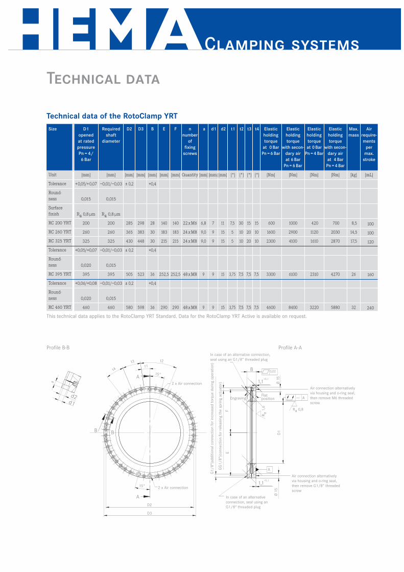
Technical data of the RotoClamp YRT
Size
Unit
Tolerance
Round-
ness
Surface
finish
RC 200 YRT
RC 260 YRT
RC 325 YRT
Tolerance
Round-
ness
RC 395 YRT
Tolerance
Round-
ness
RC 460 YRT
D1
opened
at rated
pressure
Pn = 4/
6 Bar
[mm]
+0,05/+0,07
0,015
Ra 0,8 μm
200
260
325
+0,05/+0,07
0,020
395
+0,06/+0,08
0,020
460
Required
shaft
diameter
[mm]
–0,01/–0,03
0,015
Ra 0,8 μm
200
260
325
–0,01/–0,03
0,015
395
–0,01/–0,03
0,015
460
D2
[mm]
± 0,2
285
365
430
± 0,2
505
± 0,2
580
D3
[mm]
298
383
448
523
598
B
[mm]
+0,4
28
30
30
+0,4
36
+0,4
36
t4
[°]
15
10
10
7,5
7,5
t3
[°]
15
20
20
7,5
7,5
t2
[°]
30
10
10
7,5
7,5
Elastic
holding
torque
at 0 Bar
Pn = 4 Bar
[Nm]
420
1120
1610
2310
3220
E
[mm]
140
183
215
252,5
290
F
[mm]
140
183
215
252,5
290
a
[mm]
6,8
9,0
9,0
9
9
t1
[°]
7,5
5
5
3,75
3,75
d1
[mm]
7
9
9
9
9
d2
[mm]
11
15
15
15
15
Elastic
holding
torque
at 0 Bar
Pn = 6 Bar
[Nm]
600
1600
2300
3300
4600
Elastic
holding
torque
with secon-
dary air
at 6 Bar
Pn = 6 Bar
[Nm]
1000
2900
4100
6100
8400
Elastic
holding
torque
with secon-
dary air
at 4 Bar
Pn = 4 Bar
[Nm]
700
2030
2870
4270
5880
Max.
mass
[kg]
8,5
14,5
17,5
26
32
n
number
of
fixing
screws
Quantity
22xM6
24xM8
24xM8
48xM8
48xM8
Air
require-
ments
per
max.
stroke
[mL]
100
100
120
160
240
This technical data applies to the RotoClamp YRT Standard. Data for the RotoClamp YRT Active is available on request.
Clamping systems
Technical data
Profile B-B Profile A-A
t2
15°
t3
a
d2d1
B B
A
15°
A
In case of an alternative connection,
seal using an G1/8“ threaded plug
Air connection alternatively
via housing and o-ring seal,
then remove M6 threaded
screw
Flat position
0,02
A
--- A
t4
D2
2 x Air connection
2 x Air connection
D3
Air connection alternatively
via housing and o-ring seal,
then remove G1/8“ threaded
screw
In case of an alternative
connection, seal using an
G1/8“ threaded plug
G1
/8
“(ad
dit
ion
al co
nn
ecti
on
fo
r in
cre
ase
d t
orq
ue d
uri
ng o
pera
tio
n)
GG
1/
8“(
co
nn
ecti
on
fo
r re
leasi
ng t
he s
pri
ng a
ctu
ato
r)
Ra 0,8
Ra
1,6
B
Ø 1
5
Engraving
FE
D1
Ø 1
5
1,1+0,1
1,1+0,1
t1
Technical data of the RotoClamp YRT
Size
Unit
Tolerance
Round-
ness
Surface
finish
RC 200 YRT
RC 260 YRT
RC 325 YRT
Tolerance
Round-
ness
RC 395 YRT
Tolerance
Round-
ness
RC 460 YRT
D1
opened
at rated
pressure
Pn = 4/
6 Bar
[mm]
+0,05/+0,07
0,015
Ra 0,8 μm
200
260
325
+0,05/+0,07
0,020
395
+0,06/+0,08
0,020
460
Required
shaft
diameter
[mm]
–0,01/–0,03
0,015
Ra 0,8 μm
200
260
325
–0,01/–0,03
0,015
395
–0,01/–0,03
0,015
460
D2
[mm]
± 0,2
285
365
430
± 0,2
505
± 0,2
580
D3
[mm]
298
383
448
523
598
B
[mm]
+0,4
28
30
30
+0,4
36
+0,4
36
t4
[°]
15
10
10
7,5
7,5
t3
[°]
15
20
20
7,5
7,5
t2
[°]
30
10
10
7,5
7,5
Elastic
holding
torque
at 0 Bar
Pn = 4 Bar
[Nm]
420
1120
1610
2310
3220
E
[mm]
140
183
215
252,5
290
F
[mm]
140
183
215
252,5
290
a
[mm]
6,8
9,0
9,0
9
9
t1
[°]
7,5
5
5
3,75
3,75
d1
[mm]
7
9
9
9
9
d2
[mm]
11
15
15
15
15
Elastic
holding
torque
at 0 Bar
Pn = 6 Bar
[Nm]
600
1600
2300
3300
4600
Elastic
holding
torque
with secon-
dary air
at 6 Bar
Pn = 6 Bar
[Nm]
1000
2900
4100
6100
8400
Elastic
holding
torque
with secon-
dary air
at 4 Bar
Pn = 4 Bar
[Nm]
700
2030
2870
4270
5880
Max.
mass
[kg]
8,5
14,5
17,5
26
32
n
number
of
fixing
screws
Quantity
22xM6
24xM8
24xM8
48xM8
48xM8
Air
require-
ments
per
max.
stroke
[mL]
100
100
120
160
240
This technical data applies to the RotoClamp YRT Standard. Data for the RotoClamp YRT Active is available on request.

Installation and assembly
General
To transfer the maximum clamping forces, the connection
to the machine structure should be as rigid as possible.
The characteristics indicated for the clamping elements
can only be achieved by correct construction, manu-
facturing, assembly and use of the system.
Assembly instructions of the shaft flange
The seating at the shaft should be a g6-fit. The shaft flan-
ge is placed on the flat machined side, screwed down
lightly and then aligned for smooth running.
The required tightening torque for the tightening screws
M8/12,9 is 44 Nm in order to transfer the maximum
torque.
Assembly instructions of the RotoClamp
Compressed air is applied to the RotoClamp and it is
opened. Clamping can then be initiated via the shaft. The
RotoClamp is then placed on the flat matching side and
screwed down with a reduced torque.
The compressed air is then reduced to 0 Bar, thereby
activating the clamping. This procedure centres the
clamping mechanism relative to the shaft The RotoClamp
must be free at the outer diameter (>1 mm) to ensure
safe function.
After the RotoClamp is centred in the intended position,
the fixing screws are tightened cross-wise in several
phases to the defined torque.
After fixing, the clamping mechanism is opened and a
check is made whether the shaft can be turned freely.
Only this ensures correct function.
Options/Installation
15
Ro
to
Cla
mp
Boring depth of screws
designed for DIN 6912/
DIN 7984, mounting
thread optional
Contact surface of the RotoClamp:
Diameter D3 minus 60 mm
Shaft
Optional
shaft ring
RotoClamp
Make sure that there is a rigid connection
and correct attachment to transmit the forces!
RotoClamp can also be delivered as a complete solution with
the shaft flange manufactured to your specifications using
various materials. The optional clamping flange is available
in the following qualities: hardened with case-hardened steel
or plasma-coated steel.
RotoClamp with optional shaft flange
RotoClamp
A
A
B
2x impression thread M8 Profile A-A
20
9Ra0,8
Ra1,6
AC
Ra1
,6
ø9
ø15
0,01
0,015
0,015
n counterborings for M8 screwsSize Ø A Ø B Ø C n counter-
sinkings
Tolerance H7 ±0,1 mm – 0,010
– 0,030
100 60 80 120 8
120 80 100 120 8
140 100 120 140 8
160 110 136 160 12
180 130 156 180 12
200 150 176 200 12
220 170 196 220 12
240 190 216 240 12
260 210 236 260 12
280 230 256 280 12
300 250 276 300 12
320 270 296 320 12

Clamping systems
Details of construction
View: RotoClamp Outside in mounting position (suggestion)
View: RotoClamp Inside in mounting position (suggestion)
Design recommendations
The accuracy of the clamping surface is established by
matching the precision ground inside diameter to the flat
machined mounting surface of the RotoClamp. The total
running tolerance of the clamping surface to the defined
flat matching surface is smaller than 0.02 mm.
The contact width of the clamping surface is between
2.5 and 4 mm, depending on the gap width. In this
area, compressive stresses up to max. 180 N/mm2 arise at
the clamping diameter when using the secondary air
function.
Transferable torque (example): When using 12,9 M8
screws and at a prestressing force of 30700 N for each
screw and a coefficient of friction of µ=0.1 and a radius of
100 mm, a transferable torque of 307 Nm is achieved
for each screw.
The roundness and radial eccentricity of the shaft in
assembled state should be < 0.02 mm.
The total running tolerance of the plane surface to the
shaft for attaching the clamping mechanism should be
< 0.02 mm.
The flat attachment should not be wider than D3–60 mm.
The RotoClamp must be free at the outer diameter
(RotoClamp Inside) or at the inside diameter (RotoClamp
Outside) to be able to centre itself.

17
Ro
to
Cla
mp
RotoClamp
Request form
Company name:
Address:
Contact:
Telephone: DID:
E-Mail:
Country/Zip/Location:
Area/Department:
Fax: Direct:
Internet:
Type designation according to the table:
Clamping cycles: per
special requirement:
Clamping torque: Nm
Planned connection pressure:
4 Bar 6 Bar
Dimensions:
Outer diameter D3: mm
Inside diameter D1: mm
Fixing diameter D2: mm
Overall height:
Standard bore according to drawing:
Yes No
In case of deviation, please enclose the drawing for the
application or mail to [email protected].
Optional shaft flange:
Required quantity:
Date of delivery:
Please call back Please visit
Other:
You can also download this form at:
www.hema-schutz.de.
Please send by fax to +49 6182 773-35
RotoClamp systems can be adjusted for various applications. The following criteria decide on the configuration
of the system. Please enter the information as completely and detailed as possible.
RotoClamp Outside
(on request)
RotoClamp Inside
S N L YRT
SA NA LA YRTA
Model (please check):

Clamping systems

Ro
to
Cla
mp
19
RotoClamp

LinClamp
LinClamp A
LinClamp SK
LinClamp S
LinClamp SA
Clamping systems

1
2
3
4
5
6
7
21L
inC
la
mp
Advantages
LinClamp
Suitable for almost all sizes and manufacturers
of linear guide systems (LinClamp S, SK, SA)
as well as for surfaces (LinClamp A)
Compact design, suitable for high and low
carriages, simple installation
Compatible to other rail clamping systems
Pneumatic clamping or braking
of the highest forces
Optimum safety clamping, failure
of pneumatics results in clamping
(for type S, SK, A)
Low system costs in comparison
to hydraulics and electronic solutions
Special linings for clamping without
loss of holding power for linear guides
with grease lubrication.

Operating principle of the LinClamp
Funktion LinClamp S/SK
LinClamp S/SK released Compressed air is applied to the
chamber between the two spring steel diaphragms. This de-
forms the spring steel sheets elastically and shortens them
in the horizontal direction. The clamp body is deformed in
such a way that it contacts at the top with the spring steel
sheets and expands at the bottom around the brake shoes.
This lifts the brake shoes from the rail and it can be moved
freely.
LinClamp S/SK clamped The chamber between the two
spring steel diaphragms is vented. The spring steel sheets
spring back to their normal position and expand the upper
part of the clamping body. However, this expansion at the
top simultaneously leads to a narrowing at the bottom. This
narrowing causes the brake shoes to press against the rail
and to clamp it.
Funktion LinClamp SA
LinClamp SA released Venting causes the sheet to spring
back and splays out the clamping body below the slide way.
The base plate, which has previously been reformed elasti-
cally, now springs back to its starting position. It is thereby
narrower above the cross web and wider beneath it. The
brake shoes lift off from the rail. Operating pressure 4 to 6
Bar.
LinClamp SA clamped To activate the clamping
mechanism, the chamber below the spring steel sheet is
filled with compressed air. The prestressed spring steel
sheet is thereby pressed upwards and simultaneously
stretched. Simultaneously, the lower part of the clamping
body is narrower over the cross web as pivot point. This
presses the brake shoes against the rail.
Function of the LinClamp S/SK
Function of the LinClamp SA
Standard LinClamp
rail clamping
mechanism
Opening with
spring actuator
Open Open
A1 = 1p
Standard LinClamp
rail clamping
mechanism
Clamping with
spring actuator
Close
A1 =1p
Standard LinClamp
rail clamping
mechanism
Opening with
spring actuator
Close
A1 = 0
p
Standard LinClamp
rail clamping
mechanism
Clamping with
spring actuator
Open Open
A1 = 0p
Compressed air
Clamping systems

Operating principle of the LinClamp
23
Lin
Cla
mp
Funktion LinClamp A
LinClamp A released Compressed air is applied to the
chamber between the two spring steel diaphragms. This
elastically deforms the spring steel sheets and the entire
system contracts. This contraction causes the clamping jaw
to lift from the base frame – the carriage can now be moved
freely. The gap between the clamping jaws and the frame at
an operating pressure of 4 Bar is 0.05 mm. The distance bet-
ween the carriages and the frame remains constant due to
the high accuracy of the precision rails; the gap of 0.05 mm
is therefore not a problem.
LinClamp A clamped The chamber between the two spring
steel diaphragms is vented. The energy stored in the spring
steel sheets causes the clamping element to expand towards
the machine frame. When the clamping jaws touch the
machine frame, a large part of the energy is still within the
spring actuator – the carriage is clamped.
Function of the LinClamp A
LinClamp A
Clamping with
spring actuator
Close
A1 = 0
p
LinClamp A
Opening with
spring actuator
Open
Machined
surface
Machined
surface
0,0
5 m
m
A1 =1
p
Compressed air
LinClamp
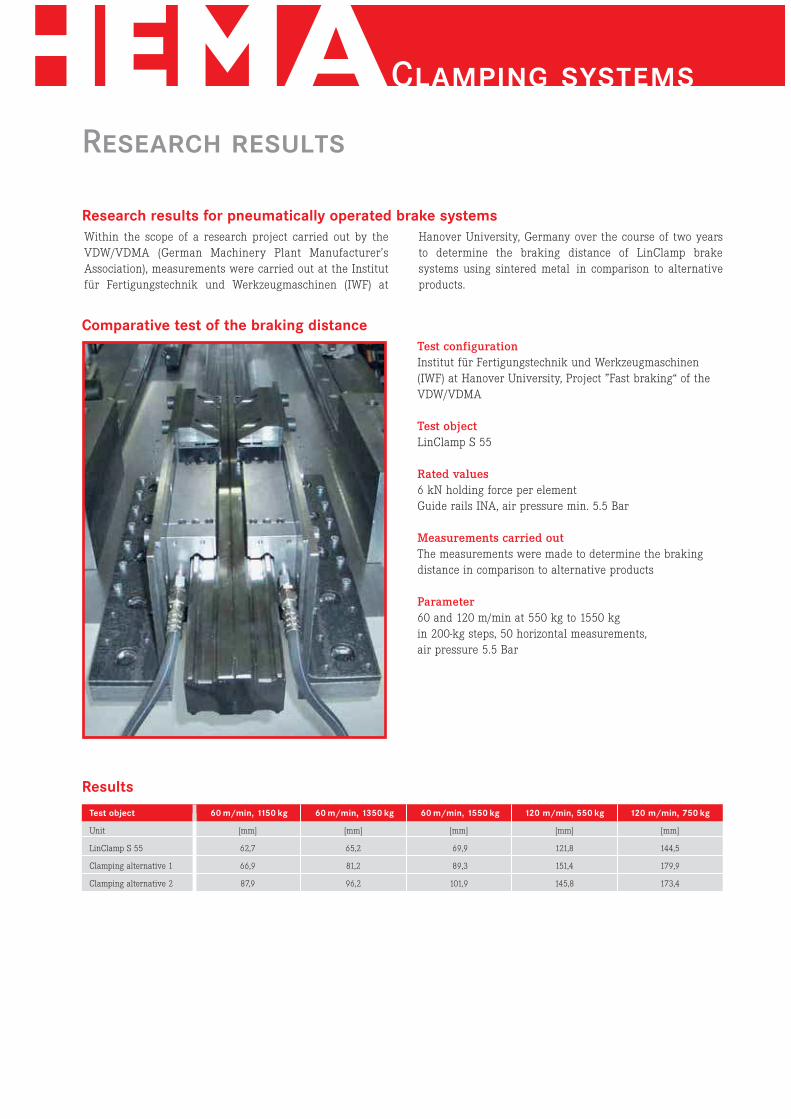
Research results
Within the scope of a research project carried out by the
VDW/VDMA (German Machinery Plant Manufacturer’s
Association), measurements were carried out at the Institut
für Fertigungstechnik und Werkzeugmaschinen (IWF) at
Hanover University, Germany over the course of two years
to determine the braking distance of LinClamp brake
systems using sintered metal in comparison to alternative
products.
Test configuration
Institut für Fertigungstechnik und Werkzeugmaschinen
(IWF) at Hanover University, Project ”Fast braking“ of the
VDW/VDMA
Test object
LinClamp S 55
Rated values
6 kN holding force per element
Guide rails INA, air pressure min. 5.5 Bar
Measurements carried out
The measurements were made to determine the braking
distance in comparison to alternative products
Parameter
60 and 120 m/min at 550 kg to 1550 kg
in 200-kg steps, 50 horizontal measurements,
air pressure 5.5 Bar
Comparative test of the braking distance
Test object
Unit
LinClamp S 55
Clamping alternative 1
Clamping alternative 2
60 m/min, 1150 kg
[mm]
62,7
66,9
87,9
60 m/min, 1350 kg
[mm]
65,2
81,2
96,2
60 m/min, 1550 kg
[mm]
69,9
89,3
101,9
120 m/min, 550 kg
[mm]
121,8
151,4
145,8
120 m/min, 750 kg
[mm]
144,5
179,9
173,4
Research results for pneumatically operated brake systems
Results
Clamping systems

25
Lin
Cla
mp
Features of LinClamp
The inner dimension I between the faces of each LinClamp
is polished to an exact value. This is always 0.01 mm to
0.03 mm larger than the maximum size Jmax from the
manufacturer documentation of the respective linear guide
rail (refer to the diagram). The greatest possible holding
force is at Jmax. In unfavourable cases, there are resulting
losses of holding force of up to 30% (refer to the table).
Gap width between brake and clamping faces and linear guide rails
Mounting of the carriages
high low
Air gap bellows/linear guide rail (mm) Loss in holding force (%)
0,01 5
0,03 10
0,05 20
0,07 30
Example: Clamping in
the middle area of a
linear guide rail
Example: Clamping in
the upper area of a
linear guide rail
A
B B
Flat face/
assembly surface
Jmax (manufacturer documentation) Jmax (manufacturer documentation)
I = Jmax + 0,01/+ 0,03
(grinding size)
I = Jmax + 0,01/+ 0,03
(grinding size)
Ra0
,8 Ra0
,8 //0,01 B //0,01 B
AFlat face/
assembly surfaceR
a0
,8 Ra0
,8
Comparison of higher/lower runner block LinClamp S:
In accordance to the configuration of the linear guide used,
you can select between a high or a low fixing element.
Clamping Braking
All S, SK, and SA type LinClamps can be used both as brake
and clamping elements.
Use as brake: Sintered metal brake lining.
Use as clamp: Clamp linings made of tool steel.
I_ 0,01 AI_ 0,01 A
LinClamp
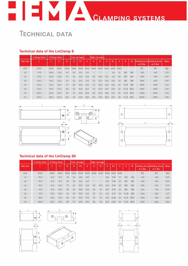
Technical data
Technical data of the LinClamp S
Rail size
Unit
20
25
30
35
45
55
65
L
[mm]
97,5
117,5
126,5
156,5
176,5
202,5
259,5
L
[mm]
105,5
125,5
141,5
171,5
191,5
221,5
281,5
L1
[mm]
93,2
113,0
121,0
151,2
171,2
196,2
251,2
B
[mm]
43
47
59
69
80
98
120
H
[mm]
30
36
42
48
60
70
90
H1
[mm]
19,5
25,0
29,5
35,0
42,0
49,0
64,0
A
[mm]
13,5
15,5
17,0
22,5
26,5
28,0
38,0
A
[mm]
–
19,5
20,0
29,5
36,5
38,0
48,0
B1
[mm]
6,0
6,0
10,0
10,0
10,0
12,5
15,0
C
[mm]
15
20
24
24
26
30
40
G
M5
M5
M5
G1/8
G1/8
G1/8
G1/8
M
M5
M6
M8
M8
M10
M12
M12
Mass
[kg]
0,32
0,50
0,90
1,26
2,30
3,90
5,00
Holding force
at 6 Bar
[N]
900
1200
1800
2800
4000
6000
10000
Holding force
at 4 Bar
[N]
540
780
1100
1800
2400
3600
6000
H
[mm]
–
40
45
55
70
80
100
H1
[mm]
–
29,0
32,5
42,0
52,0
59,0
74,0
Low carriage4 fixing holes2 fixing holes High carriage
Technical data of the LinClamp SK
Rail size
Unit
15
20
25
30
35
45
55
L
[mm]
55,5
55,5
55,5
67,0
67,0
80,0
100,0
B
[mm]
45
54
75
82
96
116
136
H
[mm]
24
30
36
42
48
60
70
H1
[mm]
18,0
22,0
25,5
30,0
35,0
45,0
49,0
A
[mm]
14,0
16,0
16,0
21,0
21,2
27,5
30,5
A
[mm]
14,0
16,0
16,0
21,0
21,2
27,5
30,5
B1
[mm]
5,00
5,00
5,00
8,75
8,75
10,00
10,00
C
[mm]
15
20
20
22
24
26
30
G
M5
M5
M5
M5
G1/8
G1/8
G1/8
M
M4
M6
M6
M8
M8
M10
M10
Mass
[kg]
0,50
0,60
0,70
0,90
1,27
2,00
2,80
Holding force
at 6 Bar
[N]
450
650
800
1150
1250
1500
2100
Holding force
at 4 Bar
[N]
300
430
530
750
820
950
1300
H
[mm]
–
–
40
45
55
70
80
H1
[mm]
–
–
29,5
33
42
55
59
Low carriage High carriage
M
G
BL L
L1 B1B1B1
A
H1
H
C
L
[mm]
61,5
61,5
61,5
76,5
76,5
92,0
112,0
L1
[mm]
51,5
51,5
51,5
59,0
59,0
72,0
92,0
4 fixing holes2 fixing holes
L B
L1B1 B1 B1
AC
H1
H
M
G
L
Clamping systems

Technical data
27L
inC
la
mp
Technical data of the LinClamp SA
Rail size
Unit
20
25
35
L
[mm]
40
40
67
B
[mm]
75
75
96
H
[mm]
30
36
48
H1
[mm]
23
23
35
A
[mm]
15
15
20
A
[mm]
15
15
20
B1
[mm]
5,00
5,00
8,75
C
[mm]
20
20
20
G
[mm]
M5
M5
G1/8
M
M6
M6
M8
Mass
[kg]
0,53
0,53
1,14
Holding force
at 6 Bar
[N]
650
800
1250
Holding force
at 4 Bar
[N]
390
480
750
H
[mm]
–
40
55
H1
[mm]
–
27
42
Low carriage2 fixing holes High carriage
Technical data of the LinClamp A
Rail size
Unit
25
35
L
[mm]
140
212
B
[mm]
28,15
29,45
H
[mm]
60
81
H1
[mm]
36
55
A
[mm]
17
19
C
[mm]
4
8
D
[mm]
6,8
6,8
E
[mm]
50
50
F
[mm]
80
150
G
[mm]
3,5
3,5
I
[mm]
17
14
J
[mm]
19
22
K
[mm]
18
18
Holding force
at 4 Bar
[N]
1100
2200
Mass
[kg]
0,53
1,15
G
L B
B1
A
H1
H
C
G
M
K
B
A
L
L
F
E
Ø D
Ø C
J
F
E
Ø C
Ø DJ
IH
1
H
LinClamp

Recommendations/Installation/Warranty
General
To be able to transmit the indicated holding forces, the
connection to the carriage(s) of the linear guide system
used should be as rigid as possible.
The mounting surface of the LinClamp is always at the
same height as the mounting surfaces of the carriages
(low or high) used in the linear guide due to the use of
high or low fixing elements. Special heights of LinClamp
as well as models adapted to lower rail sizes can be
delivered on request.
The mounting surface for fixing the LinClamp must be
perfectly machined geometrically and must be flat.
Check the air supply, line lengths and feeds and both
check and test the valve selection.
Braking element (brake linings) that are greased achieve
approx. 60% of the holding forces.
Clamping elements (steel linings) that are greased achieve
100% of the holding forces.
If the combination of tolerances is unfavourable then
there is a potential loss of holding force of up to 30 %
(due to the system).
Installation and assembly
Air Pressure is applied to the LinClamp and it is opened
(Type S, SK) or it is pushed over the rail without air
pressure (Type SA) and then attached to the mounting
surface via the fixing screws. The screws are only
tightened by hand at first.
The air pressure is now reduced to 0 Bar (Type S, SK) or
increased to the required pressure (Type SA), thereby
activating the clamping mechanism. This procedure
centres the LinClamp relative to the rail.
After the LinClamp has been centred in the intended
position, the fixing screws are tightened in several steps
up to the defined tightening torque.
After assembly, a check is made whether the LinClamp
can be freely moved over the rail when open. Only in this
way is perfect function ensured.
View: LinClamp SK in mounting position (suggestion)View: LinClamp S in mounting position (suggestion)
Clamping systems

Clamping systems

Clamping systems
PClamp
PClamp X
PClamp E

33PC
la
mp
Advantages
PClamp
1
2
3
4
5
6
7
Pneumatic clamping with high forces
Optimum safety clamping –
if the pneumatic fail the system is locked
The values of hydraulic clamps
are reached and exceeded
Low system costs in
comparison to hydraulics
Simple installation
Compact design
Wide range for many shaft
sizes can be delivered

Operating principle
Function of the PClamp N
Function of the PClamp X
Increasing power
PClamp Standard opening the spring actuator
PClamp Standard clamping with spring actuator
PClamp X opening the spring actuator
PClamp X clamping with spring actuator
Open
Open
Open
Open
A1 =1p
A1 =0
A1 =1
A1 =0
p
p
p
The building block system – more power by stacking several PClamp
modules
Intelligente Baukastenlösung: PClamp Skalierung
Einfachste Klemmkrafterhöhung durch Verwendung von
mehreren Klemmeinheiten. Durch Anordnung von bis zu
3 Klemmeinheiten zwischen Grund- und Deckplatte können
die Klemmkräfte erhöht werden.
PClamp ist geeignet für Klemmungen von Stangen mit
Durchmessern von 12 mm bis 40 mm. Flanschmaße sowie
Außenabmessungen sind analog zu den Normzylindern
ISO 6431. Die Längen variieren je nach gewünschter Klemm-
kraft. Weitere Daten und Sonderlösungen auf Anfrage.
PClamp N gelöst Die Luftkammern zwischen den Feder-
blechen werden mit Druck beaufschlagt. Die Federbleche
wölben sich, werden gespannt und gleichzeitig in radialer
Richtung verkürzt. Da die Federbleche ausgehend vom
Innendurchmesser geschlitzt sind, findet die Verkürzung am
Innendurchmesser, also an der Klemmhülse statt. Die
geschlitzte Klemmbuchse kann radial auffedern und gibt die
Stange frei.
PClamp N geklemmt Die Luftkammern zwischen den Fe-
derblechen werden entlüftet, die elastischen Federbleche keh-
ren in ihre ursprüngliche Position zurück, drücken die ge-
schlitzte Klemmbuchse gegen die Stange und klemmen diese.
PClamp N ist in diesem Zustand in der Lage, sowohl Dreh-
bewegungen als auch Linearbewegungen zu stoppen.
PClamp X gelöst Die Klemmung kann erst nach anheben
der Last entriegelt werden
PClamp X geklemmt Die Funktion von PClamp X unter-
scheidet sich von PClamp N durch eine zusätzliche Sicher-
heitsfunktion: Bei einer Notfallklemmung öffnet sich ein
Luftkanal, PClamp kann nicht gelöst werden.
Compressed air
Funktion PClamp N
PClamp N released Pressure is applied to the air chambers
between the spring steel sheets. The spring steel sheets bend
outwards, reducing their radial width. The clamping collet
can therefore expand, releasing the rod.
PClamp N clamped The air chambers between the spring
steel sheets are vented, the elastic spring steel sheets return
to their original position, thereby clamping the collet against
the rod. In this condition, the PClamp N is able to stop both
rotary motion as well as linear motion.
Funktion PClamp N
PClamp X clamped PClamp X offers an additional safety
feature: In case of emergency clamping, an air escape channel
opens, and the PClamp cannot be released.
PClamp X released The clamping can only be unlocked
after lifting the load.
Funktion PClamp N
Intelligent modular concept PClamp stacking the easiest
method of increasing the clamping force by stacking
several clamping units. The clamping forces can be increased
by arranging up to three clamping units between the base
plate and the surface plate.
PClamp is suitable for clamping rods with diameters of 12 mm
to 40 mm. The flange dimension as well as the outside dimen-
sions are matched to those of standard cylinders ISO 6431. The
lengths vary depending on the clamping force required.
Additional data for special solutions are available on request.
Clamping systems

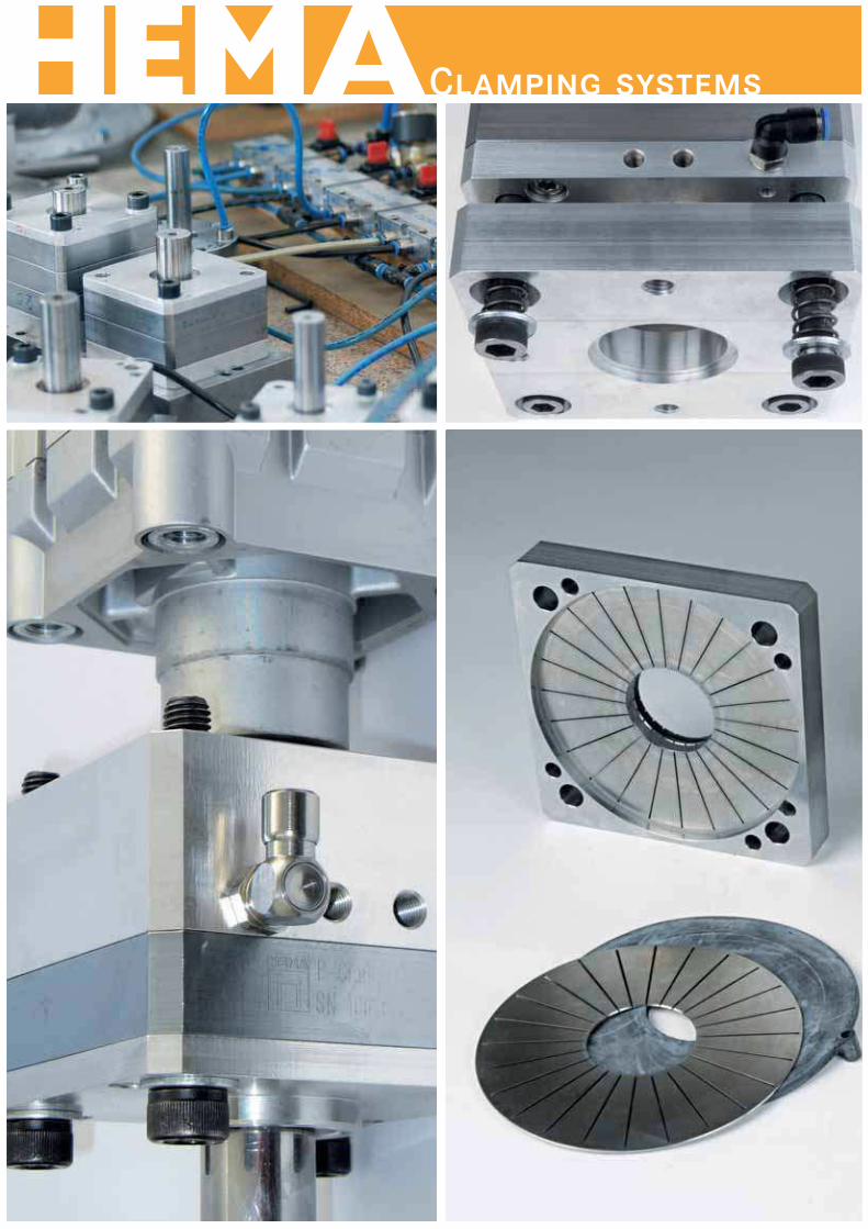
Product overview
PClamp N
35PC
la
mp
Base plate
Signal output for clamping
closed/open
Air inlet
PClamp X
Funktion PClamp N
Standard version Comprising the standard cover plate, one
to three clamping units and base plate with connections for
initiators as well as air inlet. Suitable for linear and rotary
loads.
Funktion PClamp N
Version with additional safety mechanism for highest
safety standards for vertical axes Models with improved
safety for vertical axes. After clamping the piston rod, the
clamping mechanism can only be released when the axis is
moved vertically upwards. The clamping unit is identical to
the versions N and ISO. Version PClamp X fulfils the require-
ments of the Employer’s Liability Insurance Association.
PClamp ISO
Clamping module
Cover plate
Funktion PClamp N
Version for ISO pneumatic cylinder Cover plate and base
plate are matched to the dimensions on the flange dimension
of the ISO cylinder. Due to the integrated attachments in
the housing, the ISO version is ideal for use with standard
cylinders. The clamping unit is identical to versions N and X.
PClamp E
Compact version for lower clamping forces PClamp E has
a lower overall height – ideal for applications with limited
installation space or operating ranges in which lower
holding forces are required. Sensors can not be used. The
clamping unit has a different outward appearance than
Version N, X and ISO, although the active principle is
identical.
PClamp
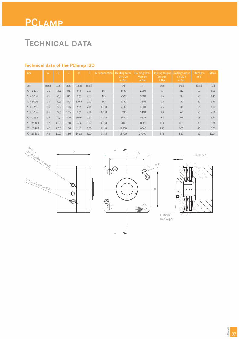
Technical data
Technical data of the PClamp ISO
M 8 x 1 (for inductive sensors)
G 1/8 Air connection
Optional
Rod wiper
A
EProfile A-A
A
A
B
D
Ø C
B
37PC
la
mp
Size
Unit
PC 63-20-1
PC 63-20-2
PC 63-20-3
PC 80-25-1
PC 80-25-2
PC 80-25-3
PC 125-40-1
PC 125-40-2
PC 125-40-3
A
[mm]
75
75
75
96
96
96
145
145
145
B
[mm]
56,5
56,5
56,5
72,0
72,0
72,0
110,0
110,0
110,0
C
[mm]
8,5
8,5
8,5
10,5
10,5
10,5
13,0
13,0
13,0
D
[mm]
69,5
87,5
105,5
67,5
87,5
107,5
95,6
119,2
142,8
E
[mm]
2,10
2,10
2,10
2,14
2,14
2,14
3,00
3,00
3,00
Mass
[kg]
1,00
1,43
1,86
1,80
2,70
5,60
3,65
8,05
10,25
Holding torque
Version
6 Bar
[Nm]
20
35
50
35
60
95
200
360
540
Holding torque
Version
4 Bar
[Nm]
15
25
35
25
40
65
140
250
375
Holding force
Version
6 Bar
[N]
2000
3600
5400
3000
5400
8100
10000
18000
27000
Holding force
Version
4 Bar
[N]
1400
2520
3780
2100
3780
5670
7000
12600
18900
Standard
rod
[mm]
20
20
20
25
25
25
40
40
40
Air connection
M5
M5
M5
G 1/8
G 1/8
G 1/8
G 1/8
G 1/8
G 1/8
PClamp
Technical data
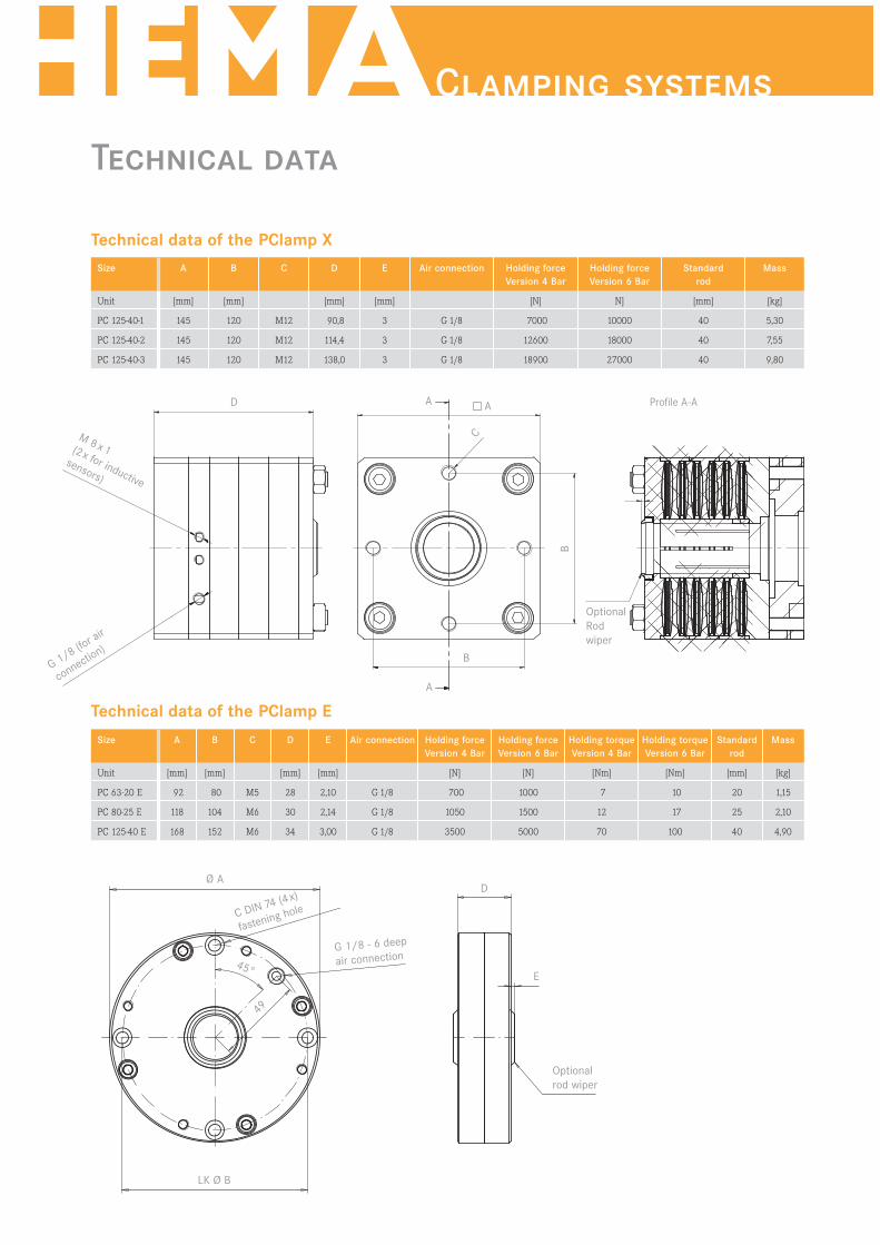
Technical data of the PClamp X
Size
Unit
PC 125-40-1
PC 125-40-2
PC 125-40-3
A
[mm]
145
145
145
B
[mm]
120
120
120
C
M12
M12
M12
D
[mm]
90,8
114,4
138,0
E
[mm]
3
3
3
Mass
[kg]
5,30
7,55
9,80
Holding force
Version 6 Bar
N]
10000
18000
27000
Holding force
Version 4 Bar
[N]
7000
12600
18900
Standard
rod
[mm]
40
40
40
Air connection
G 1/8
G 1/8
G 1/8
Technical data of the PClamp E
M 8 x 1 (2x for inductive
sensors)
G 1/8 (for a
ir
connection)
G 1/8 - 6 deep
air connection
DØ A
45°
49
E
Optional
rod wiper
LK Ø B
C DIN 74 (4x)
fastening hole
AD A
C
B
B
A
Optional
Rod
wiper
Profile A-A
Size
Unit
PC 63-20 E
PC 80-25 E
PC 125-40 E
A
[mm]
92
118
168
B
[mm]
80
104
152
C
M5
M6
M6
D
[mm]
28
30
34
E
[mm]
2,10
2,14
3,00
Mass
[kg]
1,15
2,10
4,90
Holding force
Version 6 Bar
[N]
1000
1500
5000
Holding force
Version 4 Bar
[N]
700
1050
3500
Standard
rod
[mm]
20
25
40
Air connection
G 1/8
G 1/8
G 1/8
Holding torque
Version 6 Bar
[Nm]
10
17
100
Holding torque
Version 4 Bar
[Nm]
7
12
70
Clamping systems

39PC
la
mp
Request form
Company name:
Address:
Contact:
Telephone: DID:
E-Mail:
Country/Zip/Location:
Area/Department:
Fax: Direct:
Internet:
Type designation according to the table:
Required holding force: N
Required holding torque: Nm
System can only open with air:
4 Bar compressed air
6 Bar compressed air
Horizontal operation
Vertical operation
Vertical operation (with free fall)
Use as:
brake system
clamping system
translatory
rotary
Clamping cycles: for each
Surface operating conditions:
dry oiled greased
Exact designation of the oil/grease:
Piston diameter: mm
Required quantity:
Date of delivery:
Please call back
Please visit
Other:
You can also download this form at:
www.hema-schutz.de.
Please send by fax to +49 6182 773-35
PClamp systems are suited to for various applications. The following criteria decide on the configuration
of the system. Please enter the information as completely and detailed as possible.
PClamp N PClamp ISO PClamp X PClamp E
Model (please check):
PClamp
Clamping systems

41PC
la
mp
PClamp

Clamping systems
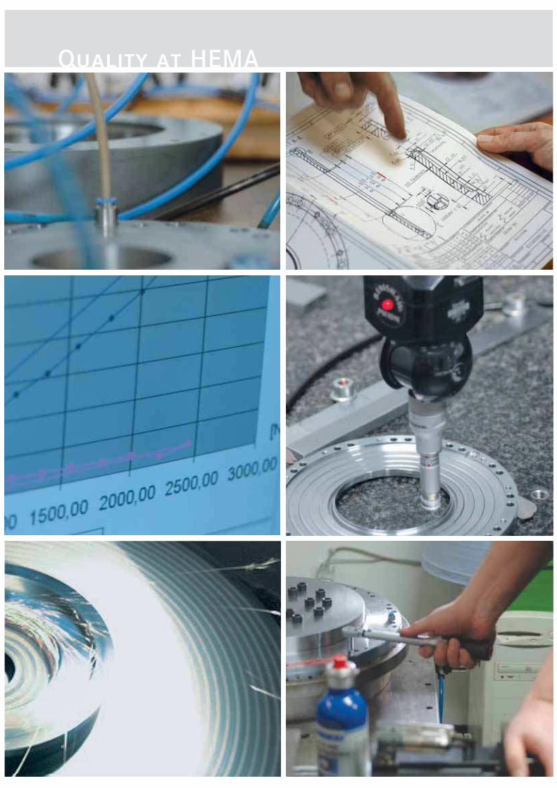
Quality at HEMA
All clamping systems are subject to the most
stringent quality requirements according to the
HEMA ISO 9001 System. A 100% check of com-
ponents at all stages of production ensures absolute
quality.
The most modern 3D measuring machines and our
own, specially developed testing machines ensure
high quality on delivery and continuous perfor-
mance data.
A batch number system allows for unique identifi-
cation of all performance data for the clamping
system delivered in each case. Detailed operating
instructions supplement the high-performance
systems.

Clamping systems
Quality at HEMA
All clamping systems are subject to the most
stringent quality requirements according to the
HEMA ISO 9001 System. A 100% check of com-
ponents at all stages of production ensures absolute
quality.
The most modern 3D measuring machines and our
own, specially developed testing machines ensure
high quality on delivery and continuous perfor-
mance data.
A batch number system allows for unique identifi-
cation of all performance data for the clamping
system delivered in each case. Detailed operating
instructions supplement the high-performance
systems.
Quality at HEMA

Released: June 2007, all rights to make changes reserved. Reprinting
and publication only with written permission of HEMA. All technical
data and drawings in this catalogue show standard guide values that
may differ in the actual situation. Please check in particular the
drilling patterns and installation situation. Values indicated are not
binding; the value indicated on the order confirmation always applies.
RotoClamp, LinClamp and PClamp are developments of InnoTech
Engineering GmbH.
HEMA Maschinen- und
Apparateschutz GmbH
Seligenstädter Straße 82
D-63500 Seligenstadt
Telefon: +49 (0)6182 773-0
Telefax: +49 (0)6182 773-35
E-Mail: [email protected]
Internet: www.hema-schutz.de
Authorized contract partner: