clark reliancedocuments.clark-reliance.com/wp-content/uploads/2013/07/...clark•reliance clark...
TRANSCRIPT
Clark•Reliance
Clark•Reliance®
For additional information contact your local Clark•Reliance representative
16633 FOLTZ INDUSTRIAL PARKWAY • STRONGSVILLE, OHIO 44136 • USA TELEPHONE: +1-440-572-1500 • FACSIMILE: +1-440-238-8828
Note: Clark Reliance shall not be liable for damages of any kind resulting in part from failure to install its products in accordance with all applicable codes and/or state and local regulations, improper application and/or maintenance
INSTRUCTION MANUAL
Clark-Reliance Boiler Safety Devices in Stationary Service for Pressures up to 250 lbs.
How to Install, Operate and Maintain... Clark-Reliance ALARM Water Columns............ Water Gage Valves.......................…..….............. PRIMATIC Water Gage Insert.........…................. Water Gage Illumination...................…............... Water Column Gage Cocks..................…........... Water Columns with Probes..................…......…
2 6 7 7 8 8
MANUAL NO. 505C
MODEL W0250-EA4: PROBE ALARM/CONTROLS
TYPE WATER COLUMN ASSEMBLY WITH TUBULAR GLASS GAGE AND TRIM

Hot torquing is suggested for all probes. However, the column must be isolated from service with the drain valve open before re-torquing the probes.The hot torquing procedure will extend probe sealing gasket life and should be performedas follows:1. Partially open steam valve to warm up the column with the drain valve slightly open.2. Close steam (and water) valves to isolate the column.3. Open the drain valve completely.4. Re-torque as instructed above.5. Return to service by closing the drain valve and opening the steam and water valves.
B. Interwiring
The wires attached to the probes must be of high temperature type in order to withstand the heat. Clark-Reliancesuggests the following types of wire:
The high temperature wires attached to the probes can be routed to a local junction box or directly to the control unit. If a junction box is used, a low cost 18 Ga. Multi-conductor cable may be used to carry the signal to the control unit. We suggest Belden #8467 or equal.
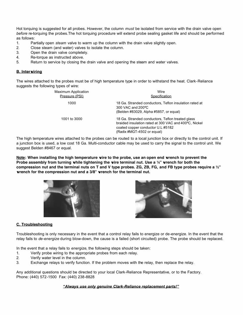
Note: When installing the high temperature wire to the probe, use an open end wrench to prevent the Probe assembly from turning while tightening the wire terminal nut. Use a ¼” wrench for both the compression nut and the terminal nuts on T and V type probes. ZG, ZB, FG, and FB type probes require a ½”wrench for the compression nut and a 3/8” wrench for the terminal nut.
C. Troubleshooting
Troubleshooting is only necessary in the event that a control relay fails to energize or de-energize. In the event that the relay fails to de-energize during blow-down, the cause is a failed (short circuited) probe. The probe should be replaced.
In the event that a relay fails to energize, the following steps should be taken:1. Verify probe wiring to the appropriate probes from each relay.2. Verify water level in the column.3. Exchange relays to verify function. If the problem moves with the relay, then replace the relay.
Any additional questions should be directed to your local Clark-Reliance Representative, or to the Factory.Phone: (440) 572-1500 Fax: (440) 238-8828
“Always use only genuine Clark-Reliance replacement parts!”
18 Ga. Stranded conductors, Teflon treated glass braided insulation rated at 300 VAC and 400ºC, Nickel coated copper conductor U.L #5182(Radix #MGT-4502 or equal)
1001 to 3000
18 Ga. Stranded conductors, Teflon insulation rated at 300 VAC and 200ºC(Belden #83029, Alpha #5857, or equal)
1000
WireSpecification
Maximum ApplicationPressure (PSI)
World’s Leader in Boiler Trim Instrumentation & Controls
Section: R400Bulletin: E189-A-2Date: 4-06-05Supersedes: E189-A-1
16633 Foltz Industrial Pkwy., Strongsville, OH 44149 USATelephone: (440) 572-1500 Fax: (440) 238-8828
www.clark-reliance.com
A. Maintenance
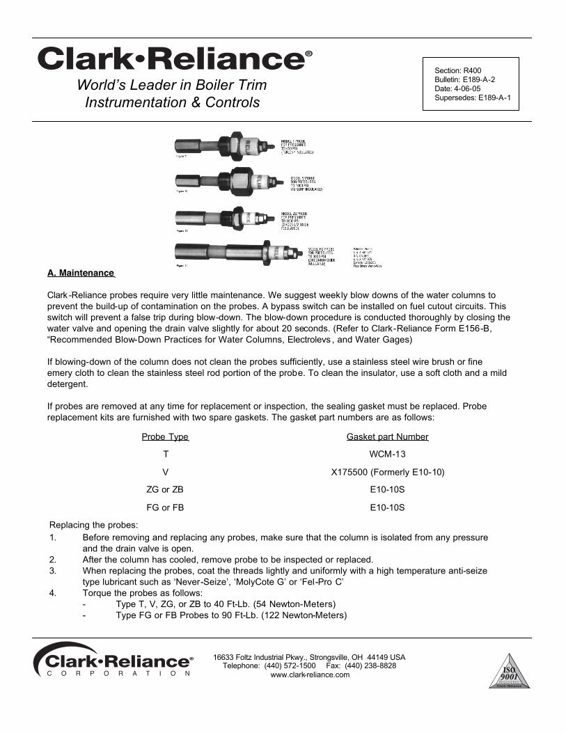
Clark -Reliance probes require very little maintenance. We suggest weekly blow downs of the water columns to prevent the build-up of contamination on the probes. A bypass switch can be installed on fuel cutout circuits. This switch will prevent a false trip during blow-down. The blow-down procedure is conducted thoroughly by closing the water valve and opening the drain valve slightly for about 20 seconds. (Refer to Clark-Reliance Form E156-B,“Recommended Blow-Down Practices for Water Columns, Electrolevs , and Water Gages)
If blowing-down of the column does not clean the probes sufficiently, use a stainless steel wire brush or fine emery cloth to clean the stainless steel rod portion of the probe. To clean the insulator, use a soft cloth and a mild detergent.
If probes are removed at any time for replacement or inspection, the sealing gasket must be replaced. Probe replacement kits are furnished with two spare gaskets. The gasket part numbers are as follows:
E10-10SFG or FB
E10-10SZG or ZB
X175500 (Formerly E10-10)V
WCM-13T
Gasket part NumberProbe Type
Replacing the probes:1. Before removing and replacing any probes, make sure that the column is isolated from any pressure
and the drain valve is open.2. After the column has cooled, remove probe to be inspected or replaced.3. When replacing the probes, coat the threads lightly and uniformly with a high temperature anti-seize
type lubricant such as ‘Never-Seize’, ‘MolyCote G’ or ‘Fel-Pro C’4. Torque the probes as follows:
- Type T, V, ZG, or ZB to 40 Ft-Lb. (54 Newton-Meters)- Type FG or FB Probes to 90 Ft-Lb. (122 Newton-Meters)
16633 Foltz Industrial Pkwy., Strongsville, OH 44149 USATelephone: (440) 572-1500 Fax: (440) 238-8828
www.clark-reliance.com
Hot torquing is suggested for all probes. However, the column must be isolated from service with the drain valve open before re-torquing the probes.The hot torquing procedure will extend probe sealing gasket life and should be performedas follows:1. Partially open steam valve to warm up the column with the drain valve slightly open.2. Close steam (and water) valves to isolate the column.3. Open the drain valve completely.4. Re-torque as instructed above.5. Return to service by closing the drain valve and opening the steam and water valves.
B. Interwiring
The wires attached to the probes must be of high temperature type in order to withstand the heat. Clark-Reliancesuggests the following types of wire:
The high temperature wires attached to the probes can be routed to a local junction box or directly to the control unit. If a junction box is used, a low cost 18 Ga. Multi-conductor cable may be used to carry the signal to the control unit. We suggest Belden #8467 or equal.
Note: When installing the high temperature wire to the probe, use an open end wrench to prevent the Probe assembly from turning while tightening the wire terminal nut. Use a ¼” wrench for both the compression nut and the terminal nuts on T and V type probes. ZG, ZB, FG, and FB type probes require a ½”wrench for the compression nut and a 3/8” wrench for the terminal nut.
C. Troubleshooting
Troubleshooting is only necessary in the event that a control relay fails to energize or de-energize. In the event that the relay fails to de-energize during blow-down, the cause is a failed (short circuited) probe. The probe should be replaced.
In the event that a relay fails to energize, the following steps should be taken:1. Verify probe wiring to the appropriate probes from each relay.2. Verify water level in the column.3. Exchange relays to verify function. If the problem moves with the relay, then replace the relay.
Any additional questions should be directed to your local Clark-Reliance Representative, or to the Factory.Phone: (440) 572-1500 Fax: (440) 238-8828
“Always use only genuine Clark-Reliance replacement parts!”
18 Ga. Stranded conductors, Teflon treated glass braided insulation rated at 300 VAC and 400ºC, Nickel coated copper conductor U.L #5182(Radix #MGT-4502 or equal)
1001 to 3000
18 Ga. Stranded conductors, Teflon insulation rated at 300 VAC and 200ºC(Belden #83029, Alpha #5857, or equal)
1000
WireSpecification
Maximum ApplicationPressure (PSI)
World’s Leader in Boiler Trim Instrumentation & Controls
Section: R400Bulletin: E189-A-2Date: 4-06-05Supersedes: E189-A-1
16633 Foltz Industrial Pkwy., Strongsville, OH 44149 USATelephone: (440) 572-1500 Fax: (440) 238-8828
www.clark-reliance.com
A. Maintenance
Clark -Reliance probes require very little maintenance. We suggest weekly blow downs of the water columns to prevent the build-up of contamination on the probes. A bypass switch can be installed on fuel cutout circuits. This switch will prevent a false trip during blow-down. The blow-down procedure is conducted thoroughly by closing the water valve and opening the drain valve slightly for about 20 seconds. (Refer to Clark-Reliance Form E156-B,“Recommended Blow-Down Practices for Water Columns, Electrolevs , and Water Gages)
If blowing-down of the column does not clean the probes sufficiently, use a stainless steel wire brush or fine emery cloth to clean the stainless steel rod portion of the probe. To clean the insulator, use a soft cloth and a mild detergent.
If probes are removed at any time for replacement or inspection, the sealing gasket must be replaced. Probe replacement kits are furnished with two spare gaskets. The gasket part numbers are as follows:
E10-10SFG or FB
E10-10SZG or ZB
X175500 (Formerly E10-10)V
WCM-13T
Gasket part NumberProbe Type
Replacing the probes:1. Before removing and replacing any probes, make sure that the column is isolated from any pressure
and the drain valve is open.2. After the column has cooled, remove probe to be inspected or replaced.3. When replacing the probes, coat the threads lightly and uniformly with a high temperature anti-seize
type lubricant such as ‘Never-Seize’, ‘MolyCote G’ or ‘Fel-Pro C’4. Torque the probes as follows:
- Type T, V, ZG, or ZB to 40 Ft-Lb. (54 Newton-Meters)- Type FG or FB Probes to 90 Ft-Lb. (122 Newton-Meters)
16633 Foltz Industrial Pkwy., Strongsville, OH 44149 USATelephone: (440) 572-1500 Fax: (440) 238-8828
www.clark-reliance.com
BOIL-OUT GAGES PRACTICE AND POLICY
On new boiler installations it is common pro-cedure initially to operate the boiler at a re-duced pressure for a short time in order to cook out foreign materials (pipe joint com-pound, grease oil, flux, etc.) that remain in the drum or other pressurized parts of the system after the boiler has been constructed. During this boil-out period most of the suspended or dissolved debris is flushed out with blowdown discharges. However, a small amount of resi-due is unavoidably deposited as a film on all internal, wetted surfaces. .. including those of the water level gage. This type of scum layer is nearly impossible to remove by blowing down the gage, particularly if the gage glasses are protected by mica shields, as they must be, in high pressure installations.
As a practical matter, it is more expedient to employ an inexpensive temporary level gage (which can be discarded or returned after the boil-out procedure), rather than to use and then rebuild the gage intended for regular ser-vice. For boil-out purposes on new water col-umns and direct-to-drum gage assemblies, Clark-Reliance
provides temporary level gage at no charge or at a refundable charge under one of the fol-lowing conditions:
1. When a Prismatic gage, flat glass gage or Simpliport gage, having 3/4" diameter end nipples, is supplied as part of a water col-umn or direct-to-drum assembly, we auto-matically furnish for temporary boil-out service the following parts at no charge:
1 pc. — ¾” OD tubular gage glass of proper length
2 pc. — Rubber packing rings (*)
1 pc. — Low visibility tubular shield (so that low vision level in the tubular gage is same as in the gage that will be used for regular service).
At the conclusion of the boil-out procedure all of the above parts should be discarded. When the gage having stainless steel nipples is then in-stalled, it is essential that the appropriate (non-rubber) packing rings are used, to assure dura-ble sealing of the stainless steel nipples.
2. When a gage having flanged connections is supplied as part of a water column or direct-to-drum assembly, and the boil-out pressure will not exceed 200 PSIG, we will furnish the following parts at no charge:
1 set — VB-991 gage valves with ½" NPT conn.
1 pc. — 5/8" OD tubular gage glass of proper length
1 pc.— Low visibility shield
The boil-out gage valves should be temporarily installed in the 1/2" NPT "Test" connections in the flanges of the regular water gage shut-off valves, which are on the water column or direct-to-drum assembly. This equipment may be dis-carded after the boil-out has been completed.
3. On installations like the above but where boil-out pressures will exceed 200 PSIG, the following are recommended for tempo-rary service:
1 set — RV1-113 gage valves with ½" NPT conn.
1 pc.— RLR-110 reflex gage of proper visi-bility (t * =No. of sections and size of each)
The cost of this assembly will be listed sepa-rately on our order invoice. However, full credit will be issued upon its return to Clark-Reliance.
* Bronze valves are supplied with rubber pack-ing rings. These are to be used for the boil-out procedure. Steel valves are supplied with pack-ing cartridges and separate rubber packing rings (to be used for boil-out).
Clark•Reliance®
16633 FOLTZ INDUSTRIAL PARKWAY • STRONGSVILLE, OHIO 44136 • USA TELEPHONE: +1-440-572-1500 • FACSIMILE: +1-440-238-8828
Note: Clark Reliance shall not be liable for damages of any kind resulting in part from failure to install its products in accordance with all applicable codes and/or state and local regulations, improper application and/or maintenance
For additional information contact your local Clark•Reliance representative
Clark•Reliance®
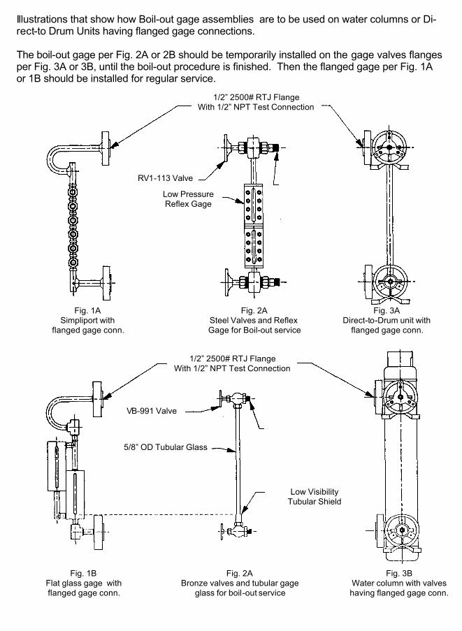
Illustrations that show how Boil-out gage assemblies are to be used on water columns or Di-rect-to Drum Units having flanged gage connections. The boil-out gage per Fig. 2A or 2B should be temporarily installed on the gage valves flanges per Fig. 3A or 3B, until the boil-out procedure is finished. Then the flanged gage per Fig. 1A or 1B should be installed for regular service.
1/2” 2500# RTJ Flange With 1/2” NPT Test Connection
RV1-113 Valve
Low Pressure Reflex Gage
Fig. 1A Simpliport with
flanged gage conn.
Fig. 2A Steel Valves and Reflex Gage for Boil-out service
Fig. 3A Direct-to-Drum unit with
flanged gage conn.
Fig. 3B Water column with valves having flanged gage conn.
1/2” 2500# RTJ Flange With 1/2” NPT Test Connection
Fig. 2A Bronze valves and tubular gage
glass for boil-out service
Fig. 1B Flat glass gage with flanged gage conn.
VB-991 Valve
5/8” OD Tubular Glass
Low Visibility Tubular Shield
Clark•Reliance®
Clark•Reliance®
For additional information contact your local Clark•Reliance representative
16633 FOLTZ INDUSTRIAL PARKWAY • STRONGSVILLE, OHIO 44136 • USA TELEPHONE: +1-440-572-1500 • FACSIMILE: +1-440-238-8828
Note: Clark Reliance shall not be liable for damages of any kind resulting in part from failure to install its products in accordance with all applicable codes and/or state and local regulations, improper application and/or maintenance
It is common practice to blow-down water columns and gage glasses. However, the fre-quency and method of blow-down may affect service life and performance of this equipment. Clark-Reliance suggests the following blow-down procedure:
1. Close both the steam and water valves between the boiler drum and the water column or water gage.
2. Open the drain valve fully on the bottom of the water column or water gage.
3. Crack open the steam valve and allow a gentle rush of steam to pass through the water column or water gage for no longer than 20 seconds.
4. Close the steam valve.
5. Inspect the water gage to insure that all foreign matter is flushed from the glass or mica. If the gage is not visually clean, repeat steps 3 and 4.
6. Close the blow-down valve and simultaneously open the steam and water valves, slowly bringing the equipment back to a normal operating level.
Note:
1. Any trip or alarm circuits that are actuated by the equipment being blown-down should be bypassed to prevent false alarms during the blow-down process.
2. Blow-down should be conducted on a weekly basis, or as necessary, based on water quality.
Recommended Blow-Down Practices For Water Columns, Electrolevs and Water Gages
Form E156-B
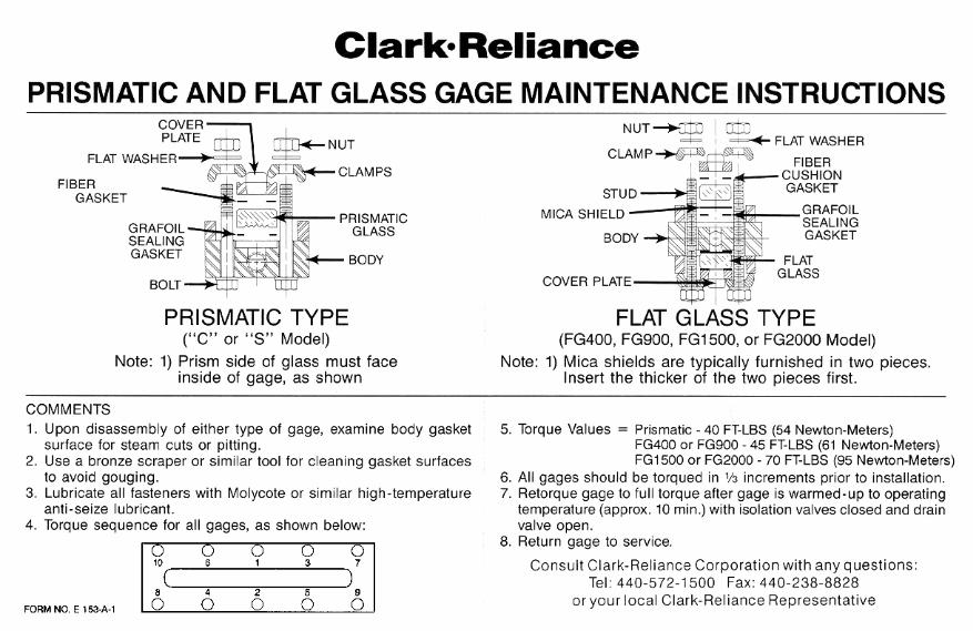
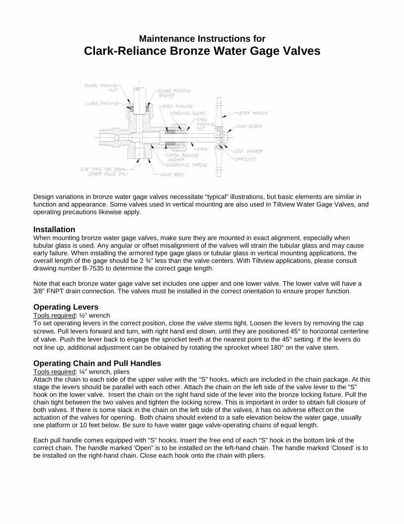
Maintenance Instructions forClark-Reliance Bronze Water Gage Valves
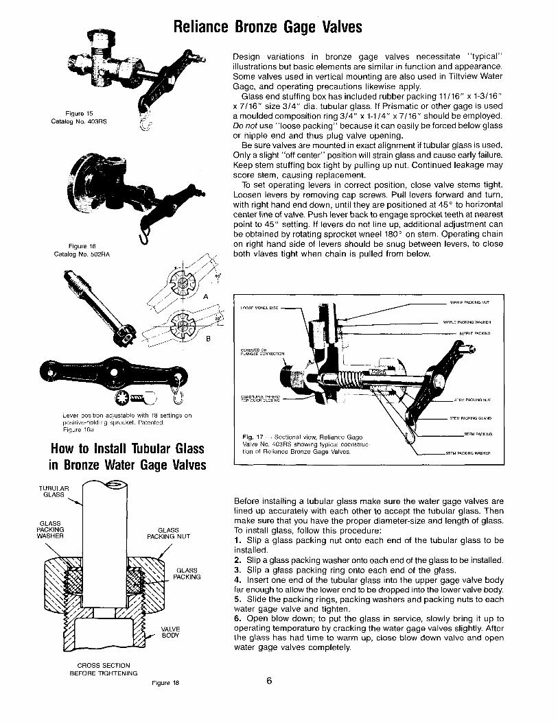
Design variations in bronze water gage valves necessitate “typical” illustrations, but basic elements are similar infunction and appearance. Some valves used in vertical mounting are also used in Tiltview Water Gage Valves, andoperating precautions likewise apply.
InstallationWhen mounting bronze water gage valves, make sure they are mounted in exact alignment, especially whentubular glass is used. Any angular or offset misalignment of the valves will strain the tubular glass and may causeearly failure. When installing the armored type gage glass or tubular glass in vertical mounting applications, theoverall length of the gage should be 2 ¾” less than the valve centers. With Tiltview applications, please consultdrawing number B-7535 to determine the correct gage length.
Note that each bronze water gage valve set includes one upper and one lower valve. The lower valve will have a3/8” FNPT drain connection. The valves must be installed in the correct orientation to ensure proper function.
Operating LeversTools required: ½” wrenchTo set operating levers in the correct position, close the valve stems tight. Loosen the levers by removing the capscrews. Pull levers forward and turn, with right hand end down, until they are positioned 45° to horizontal centerlineof valve. Push the lever back to engage the sprocket teeth at the nearest point to the 45° setting. If the levers donot line up, additional adjustment can be obtained by rotating the sprocket wheel 180° on the valve stem.
Operating Chain and Pull HandlesTools required: ¼” wrench, pliersAttach the chain to each side of the upper valve with the “S” hooks, which are included in the chain package. At thisstage the levers should be parallel with each other. Attach the chain on the left side of the valve lever to the “S”hook on the lower valve. Insert the chain on the right hand side of the lever into the bronze locking fixture. Pull thechain tight between the two valves and tighten the locking screw. This is important in order to obtain full closure ofboth valves. If there is some slack in the chain on the left side of the valves, it has no adverse effect on theactuation of the valves for opening. Both chains should extend to a safe elevation below the water gage, usuallyone platform or 10 feet below. Be sure to have water gage valve-operating chains of equal length.
Each pull handle comes equipped with “S” hooks. Insert the free end of each “S” hook in the bottom link of thecorrect chain. The handle marked ‘Open” is to be installed on the left-hand chain. The handle marked ‘Closed’ is tobe installed on the right-hand chain. Close each hook onto the chain with pliers.
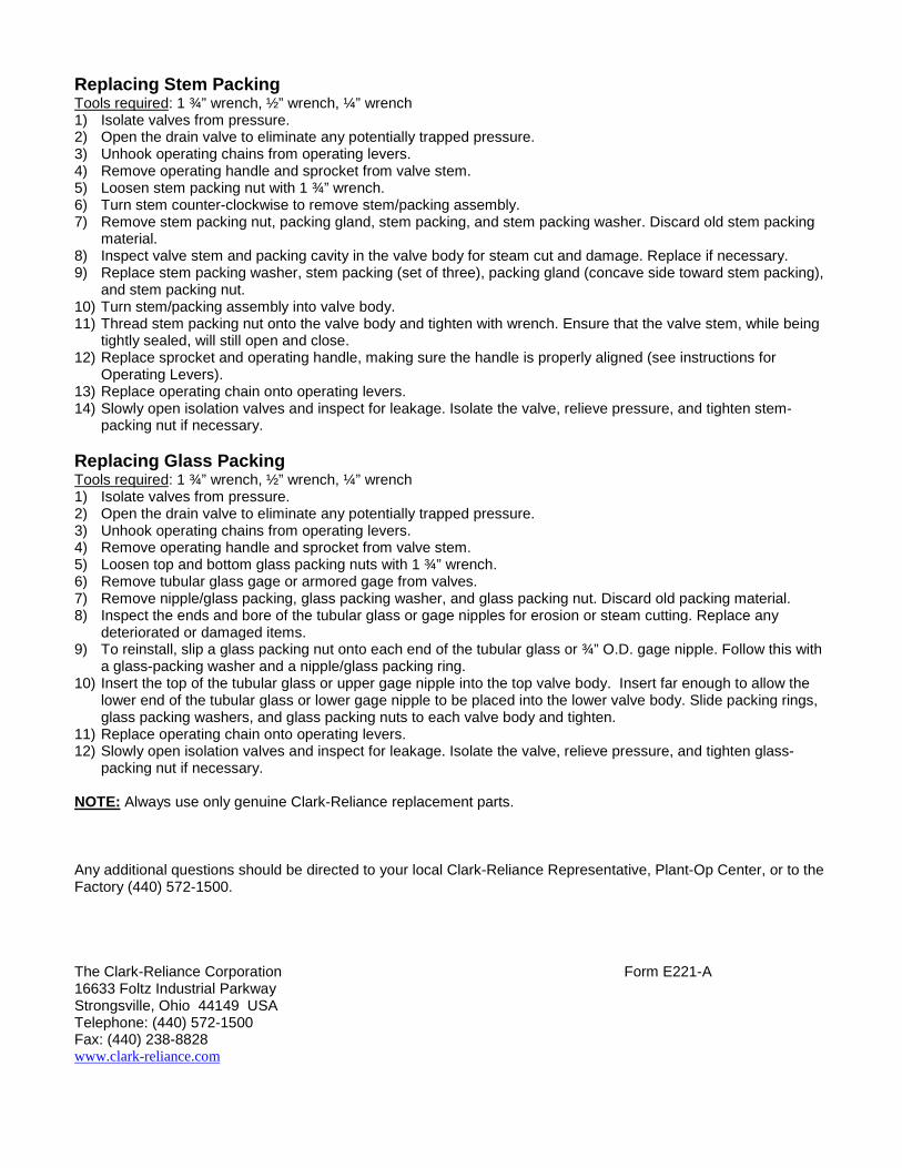
Replacing Stem PackingTools required: 1 ¾” wrench, ½” wrench, ¼” wrench1) Isolate valves from pressure.2) Open the drain valve to eliminate any potentially trapped pressure.3) Unhook operating chains from operating levers.4) Remove operating handle and sprocket from valve stem.5) Loosen stem packing nut with 1 ¾” wrench.6) Turn stem counter-clockwise to remove stem/packing assembly.7) Remove stem packing nut, packing gland, stem packing, and stem packing washer. Discard old stem packing
material.8) Inspect valve stem and packing cavity in the valve body for steam cut and damage. Replace if necessary.9) Replace stem packing washer, stem packing (set of three), packing gland (concave side toward stem packing),
and stem packing nut.10) Turn stem/packing assembly into valve body.11) Thread stem packing nut onto the valve body and tighten with wrench. Ensure that the valve stem, while being
tightly sealed, will still open and close.12) Replace sprocket and operating handle, making sure the handle is properly aligned (see instructions for
Operating Levers).13) Replace operating chain onto operating levers.14) Slowly open isolation valves and inspect for leakage. Isolate the valve, relieve pressure, and tighten stem-
packing nut if necessary.
Replacing Glass PackingTools required: 1 ¾” wrench, ½” wrench, ¼” wrench1) Isolate valves from pressure.2) Open the drain valve to eliminate any potentially trapped pressure.3) Unhook operating chains from operating levers.4) Remove operating handle and sprocket from valve stem.5) Loosen top and bottom glass packing nuts with 1 ¾” wrench.6) Remove tubular glass gage or armored gage from valves.7) Remove nipple/glass packing, glass packing washer, and glass packing nut. Discard old packing material.8) Inspect the ends and bore of the tubular glass or gage nipples for erosion or steam cutting. Replace any
deteriorated or damaged items.9) To reinstall, slip a glass packing nut onto each end of the tubular glass or ¾” O.D. gage nipple. Follow this with
a glass-packing washer and a nipple/glass packing ring.10) Insert the top of the tubular glass or upper gage nipple into the top valve body. Insert far enough to allow the
lower end of the tubular glass or lower gage nipple to be placed into the lower valve body. Slide packing rings,glass packing washers, and glass packing nuts to each valve body and tighten.
11) Replace operating chain onto operating levers.12) Slowly open isolation valves and inspect for leakage. Isolate the valve, relieve pressure, and tighten glass-
packing nut if necessary.
NOTE: Always use only genuine Clark-Reliance replacement parts.
Any additional questions should be directed to your local Clark-Reliance Representative, Plant-Op Center, or to theFactory (440) 572-1500.
The Clark-Reliance Corporation Form E221-A16633 Foltz Industrial ParkwayStrongsville, Ohio 44149 USATelephone: (440) 572-1500Fax: (440) 238-8828www.clark-reliance.com
World Leaders in Boiler Level Indication & Control
Section: M100Bulletin: E-207-ADate: 7/1/01Supercedes: NEW
R
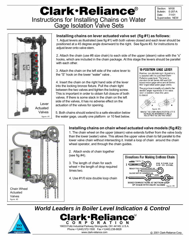
Instructions for Installing Chains on WaterGage Isolation Valve Sets
© 2000 Clark-Reliance Corp.2001 Clark-Reliance Corp.
LeverActuated
Valvesfigure #1
figure #3
Chain WheelActuatedValvesfigure #2
16633 Foltz Industrial Parkway Strongsville, OH 44149, U.S.A.Phone +1(440) 572-1500 Fax +1(440) 238-8828
www.clark-reliance.com
C O R P O R A T I O N
R
Installing chains on lever actuated valve set (fig #1) as follows:1. Adjust levers as illustrated (see fig #1) with both valves closed and each lever should bepositioned at a 45 degree angle downward to the right. See figure #3. for instructions toadjust lever onto valve stem.
2. Attach the chain (use #8 size chain) to each side of the upper (steam) valve with the “s”hooks, which are included in the chain package. At this stage the levers should be parallelwith each other.
3. Attach the chain on the left side of the valve lever tothe “S” hook on the lower “water” valve .
4. Insert the chain on the right hand side of the leverinto the locking bronze fixture. Pull the chain tightbetween the two valves and tighten the locking screw.This is important in order to obtain full closure of bothvalves. If there is some slack in the chain on the leftside of the valves, it has no adverse effect on theactuation of the valves for opening.
5. Both chains should extend to a safe elevation belowthe water gage, usually one platform or 10 feet below.
Installing chains on chain wheel actuated valve models (fig #2):1. The chain wheel on the upper (steam) valve extends further from the valve bodythan the lower (water) valve. This allows the upper valve chain to fall parallel to thelower valve chain without intersecting it. Install a loop of chain around the chainwheel operator, and through the chain guides.
2. Attach ends of chain together(see fig #4).
3. The length of chain for eachwheel = the length of drop requiredtimes two.
4. Use #1/0 size double loop chain
figure #4
registered
ISO9001