class 40 locomotive - armstrong powerhouse · pdf fileclass 40 locomotive contents ... you...
TRANSCRIPT
Page 1
Class 40
Locomotive
Contents How to install .......................................................................................................................................... 2 Important functionality information....................................................................................................... 2 Technical information ............................................................................................................................. 3 Main variants .......................................................................................................................................... 4 Detailed variants ..................................................................................................................................... 7 Cab guide .............................................................................................................................................. 11
Vacuum braked - driver’s side .......................................................................................................... 11 Vacuum braked - second man’s side ................................................................................................ 12 Dual braked cab ................................................................................................................................ 13 Bulkhead wall .................................................................................................................................... 13
Keyboard controls ................................................................................................................................. 14 Features ................................................................................................................................................ 15
Options screen .................................................................................................................................. 16 Brake selector switch ........................................................................................................................ 17 Locomotive faults .............................................................................................................................. 18
Traction motor failure ................................................................................................................... 18 High engine temperature .............................................................................................................. 18
Steam heat boiler .............................................................................................................................. 19 Filling the water tanks whilst stationary ....................................................................................... 19 Filling the water tanks whilst moving ........................................................................................... 19 Preparing the boiler ...................................................................................................................... 20 Starting the boiler ......................................................................................................................... 20
Cold start ........................................................................................................................................... 20 Preparing the locomotive ..................................................................................................................... 22 Driving guide ......................................................................................................................................... 23 How to use in the scenario editor ......................................................................................................... 24
How to place ..................................................................................................................................... 24 Numbering ........................................................................................................................................ 25
Scenarios ............................................................................................................................................... 26 Credits ................................................................................................................................................... 27
Page 2
How to install
1) Locate where you have downloaded this pack and unzip it. Information on
how to do this can be found here.
2) Go to the location where you have extracted the files from the .zip file.
3) Now find the .exe file called ‘Class 40 Locomotive Pack’. Double-click this file.
4) Follow the steps and by the end of the process, this pack will have installed.
5) If you intend to use any of the included scenarios, make sure you have the
freely available extra stock pack and relevant payware add-on packs listed on
the product page installed so the scenarios function as intended.
Important functionality information • To make sure the engine sounds work correctly in this pack, please ensure
that if you have been using the simulator beforehand, restart it before loading
a scenario featuring this locomotive. This includes if you are loading a scenario
direct from the scenario editor to the simulator. This is due to a fault with the
simulator.
• If you would like to save a scenario when using this locomotive and return to
it at a later time, you must come carry out the following procedure which is
due to the very complex scripting that has been implemented in this pack:
Saving the scenario
1) Come to a stop.
2) Press the ‘S’ key to move the Reverser into the ‘Off’ position.
3) Press the ‘E’ key to remove the master key.
4) Press the ‘Ctrl+-‘ key to move to the other cab.
5) Press the ‘Ctrl+B’ key to switch in the battery isolation switch
6) Save the scenario.
Resuming the scenario
1) Resume the scenario.
2) Press the ‘Ctrl+B’ key to switch out the battery isolation switch
3) Press the ‘Ctrl+-‘ key to move to the other cab.
4) Press the ‘E’ key to insert the master key.
5) Ensure the AWS change end switch is in the ‘On’ position.
6) Press the ‘Q’ key to reset the AWS self-test.
Page 3
Technical information
Manufacturer Vulcan Foundry/ Robert Stephenson and Hawthorns
Years built 1958 - 1962
Number built 200 (D200 - D399)
Engine English Electric 16SVT MkII
Maximum speed 90mph (140km/h)
Coupling type Screw
Length 21.18m
Height 3.91m
Width 2.74m
Weight 135 tonnes
Page 4
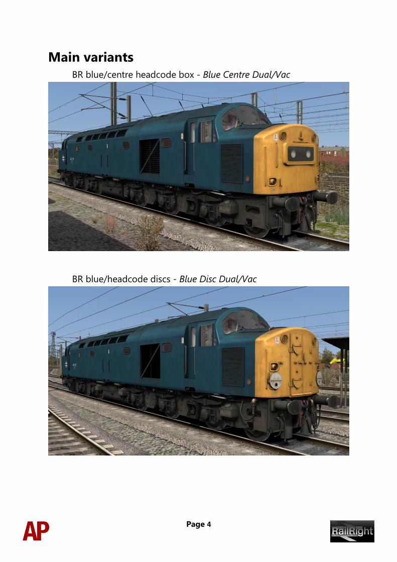
Main variants
BR blue/centre headcode box - Blue Centre Dual/Vac
BR blue/headcode discs - Blue Disc Dual/Vac
Page 5
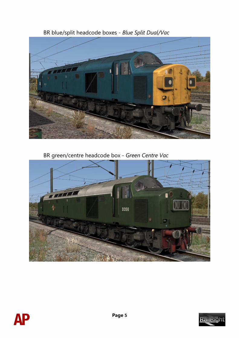
BR blue/split headcode boxes - Blue Split Dual/Vac
BR green/centre headcode box - Green Centre Vac
Page 6
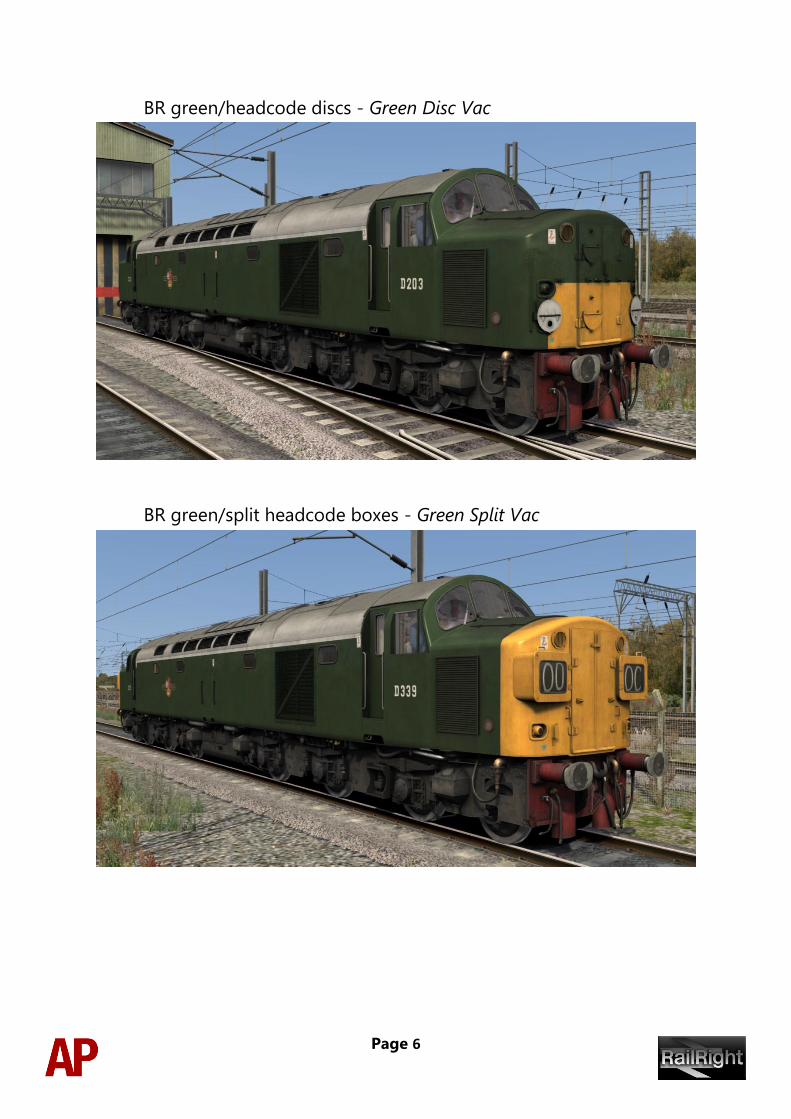
BR green/headcode discs - Green Disc Vac
BR green/split headcode boxes - Green Split Vac
Page 7
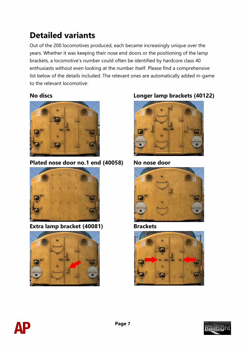
Detailed variants Out of the 200 locomotives produced, each became increasingly unique over the
years. Whether it was keeping their nose end doors or the positioning of the lamp
brackets, a locomotive’s number could often be identified by hardcore class 40
enthusiasts without even looking at the number itself. Please find a comprehensive
list below of the details included. The relevant ones are automatically added in-game
to the relevant locomotive:
No discs Longer lamp brackets (40122)
Plated nose door no.1 end (40058) No nose door
Extra lamp bracket (40081) Brackets
Page 8
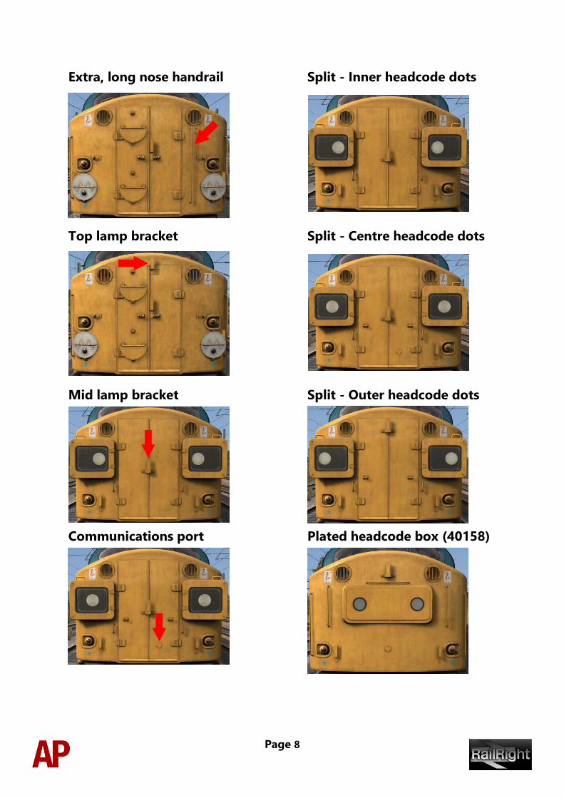
Extra, long nose handrail Split - Inner headcode dots
Top lamp bracket Split - Centre headcode dots
Mid lamp bracket Split - Outer headcode dots
Communications port Plated headcode box (40158)
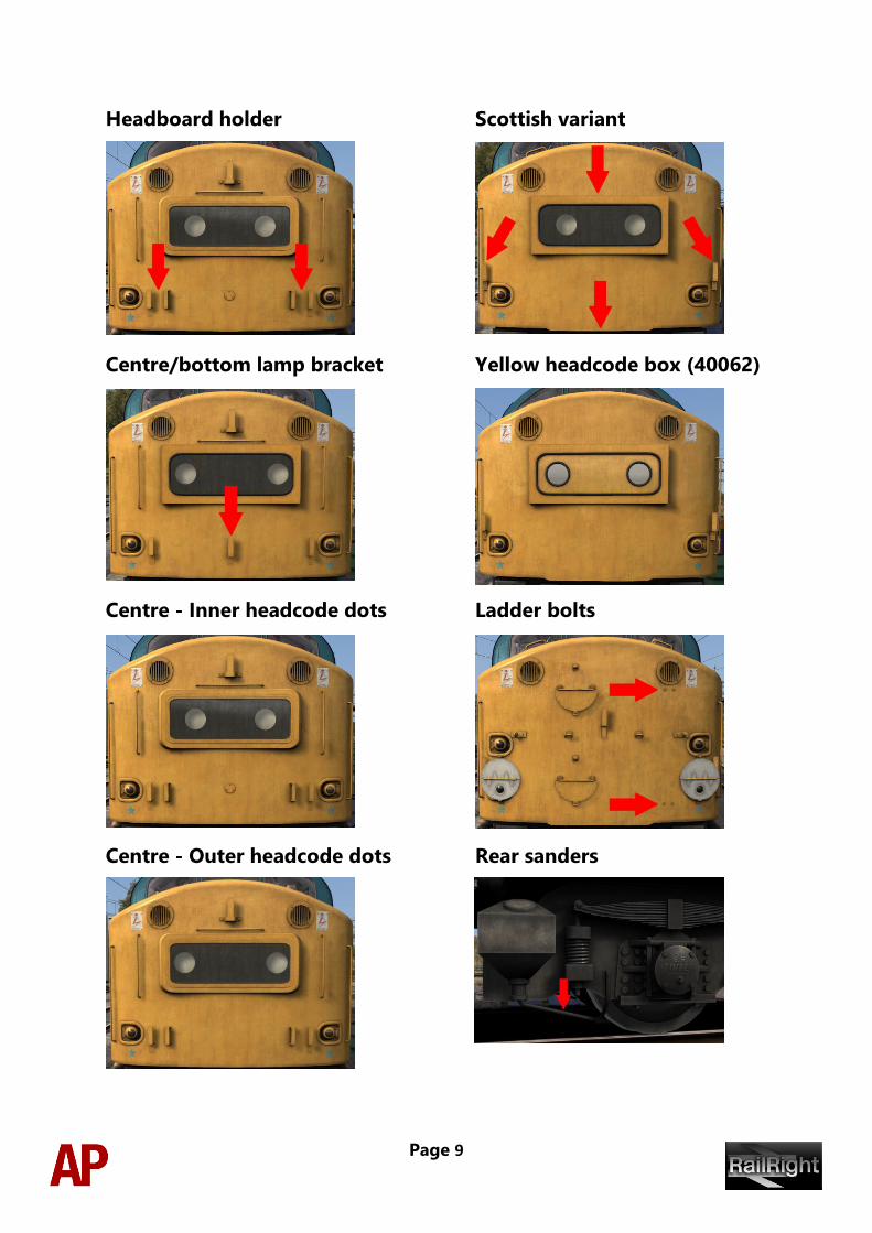
Page 9
Headboard holder Scottish variant
Centre/bottom lamp bracket Yellow headcode box (40062)
Centre - Inner headcode dots Ladder bolts
Centre - Outer headcode dots Rear sanders
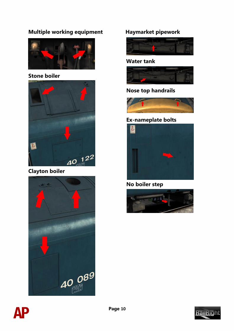
Page 10
Multiple working equipment Haymarket pipework
Water tank
Stone boiler
Nose top handrails
Ex-nameplate bolts
Clayton boiler
No boiler step
Page 11
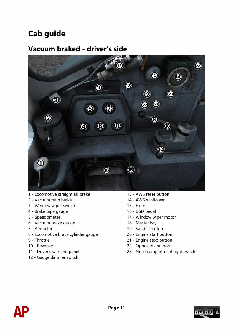
Cab guide
Vacuum braked - driver’s side
1 - Locomotive straight air brake 13 - AWS reset button
2 - Vacuum train brake 14 - AWS sunflower
3 - Window wiper switch 15 - Horn
4 - Brake pipe gauge 16 - DSD pedal
5 - Speedometer 17 - Window wiper motor
6 - Vacuum brake gauge 18 - Master key
7 - Ammeter 19 - Sander button
8 - Locomotive brake cylinder gauge 20 - Engine start button
9 - Throttle 21 - Engine stop button
10 - Reverser 22 - Opposite end horn
11 - Driver’s warning panel 23 - Nose compartment light switch
12 - Gauge dimmer switch
Page 12
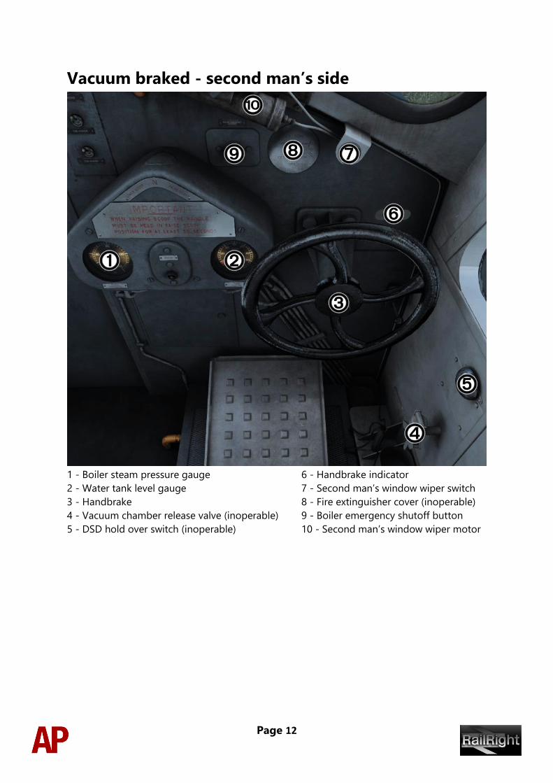
Vacuum braked - second man’s side
1 - Boiler steam pressure gauge 6 - Handbrake indicator
2 - Water tank level gauge 7 - Second man’s window wiper switch
3 - Handbrake 8 - Fire extinguisher cover (inoperable)
4 - Vacuum chamber release valve (inoperable) 9 - Boiler emergency shutoff button
5 - DSD hold over switch (inoperable) 10 - Second man’s window wiper motor
Page 13
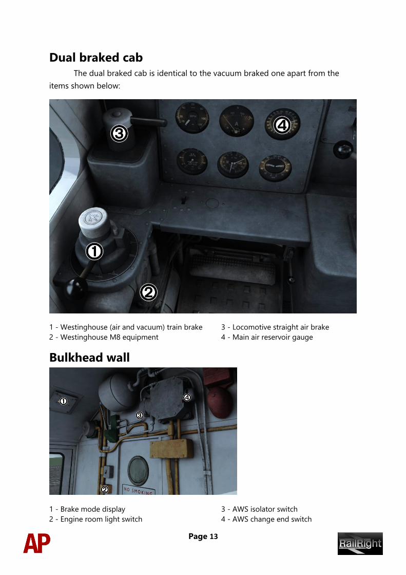
Dual braked cab The dual braked cab is identical to the vacuum braked one apart from the
items shown below:
1 - Westinghouse (air and vacuum) train brake 3 - Locomotive straight air brake
2 - Westinghouse M8 equipment 4 - Main air reservoir gauge
Bulkhead wall
1 - Brake mode display 3 - AWS isolator switch
2 - Engine room light switch 4 - AWS change end switch
Page 14
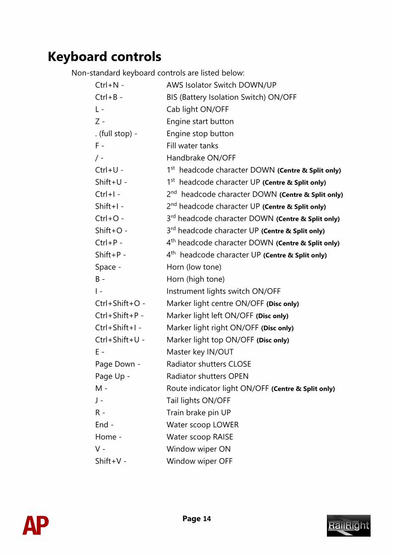
Keyboard controls Non-standard keyboard controls are listed below:
Ctrl+N - AWS Isolator Switch DOWN/UP
Ctrl+B - BIS (Battery Isolation Switch) ON/OFF
L - Cab light ON/OFF
Z - Engine start button
. (full stop) - Engine stop button
F - Fill water tanks
/ - Handbrake ON/OFF
Ctrl+U - 1st headcode character DOWN (Centre & Split only)
Shift+U - 1st headcode character UP (Centre & Split only)
Ctrl+I - 2nd headcode character DOWN (Centre & Split only)
Shift+I - 2nd headcode character UP (Centre & Split only)
Ctrl+O - 3rd headcode character DOWN (Centre & Split only)
Shift+O - 3rd headcode character UP (Centre & Split only)
Ctrl+P - 4th headcode character DOWN (Centre & Split only)
Shift+P - 4th headcode character UP (Centre & Split only)
Space - Horn (low tone)
B - Horn (high tone)
I - Instrument lights switch ON/OFF
Ctrl+Shift+O - Marker light centre ON/OFF (Disc only)
Ctrl+Shift+P - Marker light left ON/OFF (Disc only)
Ctrl+Shift+I - Marker light right ON/OFF (Disc only)
Ctrl+Shift+U - Marker light top ON/OFF (Disc only)
E - Master key IN/OUT
Page Down - Radiator shutters CLOSE
Page Up - Radiator shutters OPEN
M - Route indicator light ON/OFF (Centre & Split only)
J - Tail lights ON/OFF
R - Train brake pin UP
End - Water scoop LOWER
Home - Water scoop RAISE
V - Window wiper ON
Shift+V - Window wiper OFF
Page 15
Features
• All 200 examples represented with their numerous visual differences for both
BR blue and green liveries
• Detailed internal & external audio
• Accurate performance physics
• Dynamic exhaust smoke
• 25 individually modelled nameplates (BR green D210-D235 except D226)
• Separate vacuum and dual braked cabs
• Options screen
• Functional brake modes (air/vacuum/passenger/goods)
• Locomotive faults
• Steam heat boiler
• Cold start option
• Player changeable headcode blinds
• Finite sanders
• BIS (Battery Isolation Switch) functionality
• Working master key
• Prototypical reverser function
• AWS self-test
• Opening cab doors and windows
• Cab instrument lighting
Page 16
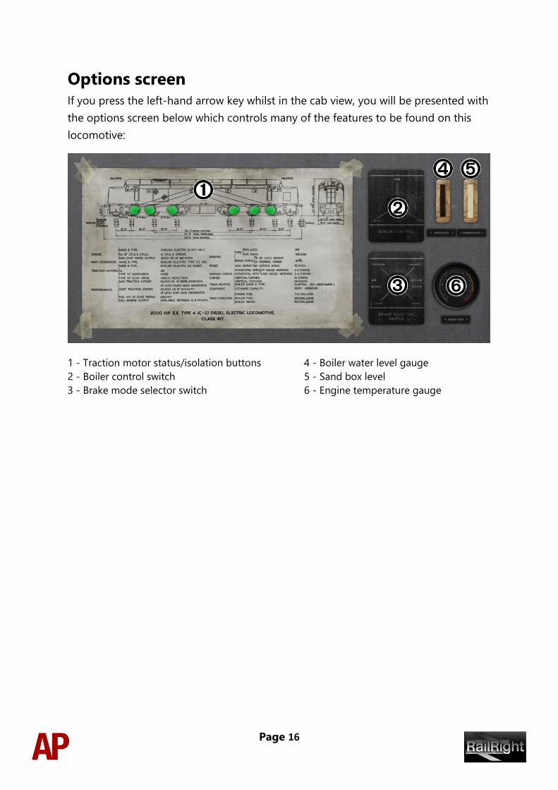
Options screen If you press the left-hand arrow key whilst in the cab view, you will be presented with
the options screen below which controls many of the features to be found on this
locomotive:
1 - Traction motor status/isolation buttons 4 - Boiler water level gauge
2 - Boiler control switch 5 - Sand box level
3 - Brake mode selector switch 6 - Engine temperature gauge
Page 17
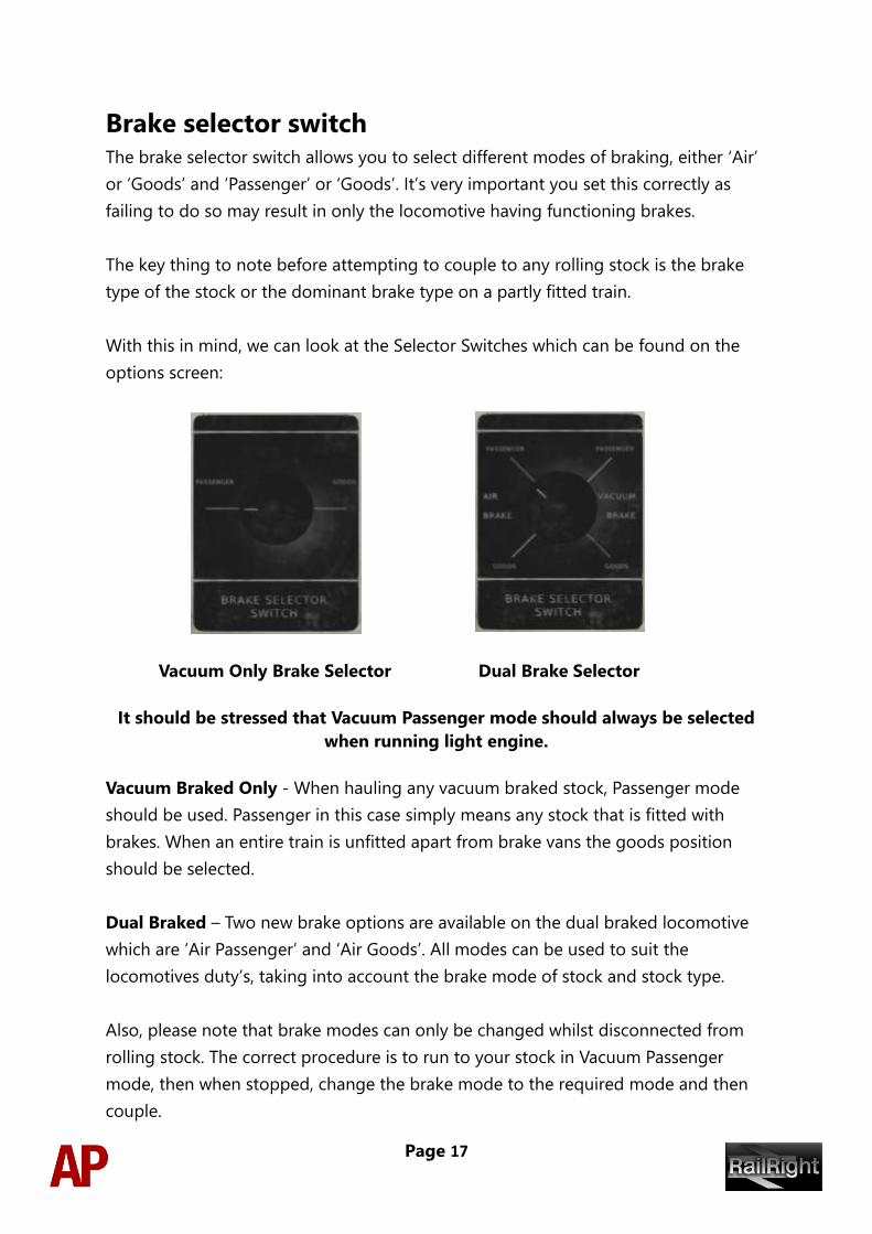
Brake selector switch The brake selector switch allows you to select different modes of braking, either ‘Air’
or ‘Goods’ and ‘Passenger’ or ‘Goods’. It’s very important you set this correctly as
failing to do so may result in only the locomotive having functioning brakes.
The key thing to note before attempting to couple to any rolling stock is the brake
type of the stock or the dominant brake type on a partly fitted train.
With this in mind, we can look at the Selector Switches which can be found on the
options screen:
Vacuum Only Brake Selector Dual Brake Selector
It should be stressed that Vacuum Passenger mode should always be selected
when running light engine.
Vacuum Braked Only - When hauling any vacuum braked stock, Passenger mode
should be used. Passenger in this case simply means any stock that is fitted with
brakes. When an entire train is unfitted apart from brake vans the goods position
should be selected.
Dual Braked – Two new brake options are available on the dual braked locomotive
which are ‘Air Passenger’ and ‘Air Goods’. All modes can be used to suit the
locomotives duty’s, taking into account the brake mode of stock and stock type.
Also, please note that brake modes can only be changed whilst disconnected from
rolling stock. The correct procedure is to run to your stock in Vacuum Passenger
mode, then when stopped, change the brake mode to the required mode and then
couple.
Page 18
Locomotive faults
Traction motor failure
This fault occurs when the locomotive amps have been pushed to their limits for as
little as 20 seconds. To prevent a flashover, 2600 amps or over may only be used for a
very brief period, 2000 – 2500 amps up to 5 minutes, 1800 – 2000 up to half an hour
and anything below 1800 is allowed constantly.
If a flashover occurs it is due to one of the above excessive stresses put on the
traction motors. Any one of six can fail resulting in loss of tractive power and the
need to isolate the now unusable motor. To isolate the motor, the engine must firstly
be shut down and then on the options screen, the damaged motor will show red,
click the red motor and it should turn black. Now you have isolated that motor, you
can start the engine and continue as normal.
Traction motors can be isolated even if they are healthy (green) by clicking on one
with the engine off. They can also be clicked again once isolated to reconnect them.
High engine temperature
This fault occurs when the locomotive has been worked hard, usually at low speeds.
This matter can be made worse if the radiator shutters are closed on the locomotive
leading to the warm engine room compartment circulating hot air through the
cooling system.
Even with the radiator shutters open, you may still run into issues. In this instance the
fault light in the cab will illuminate indicating the high temperature. At this point, the
driver should reduce power and allow the engine to cool before attempting to apply
power again. If the fault light is ignored and temperatures continue to rise, the
engine will shut down upon reaching danger levels.
Once the engine shuts down, you must wait for the temperature to fall into the safe
zone before restarting. The temperature gauge is visible in the options menu with
the safe zone denoted as green.
Page 19
Steam heat boiler The steam heat boiler is primarily used to provide heating to coaching stock in the
colder months of the year. Below is the method that should be taken to start the
boiler.
If you are using the ‘cold’ variant of the locomotive, you will need to fill the water
tank which can either be carried out whilst stationary or on the move (Green locos
only), using the water scoop at a water trough. The standard/warm variant of the
locomotive already has water in the tank but you may need to replenish on long
journeys.
First of all, in the scenario editor, you must place two scenario markers which can be
activated by clicking the ‘ScenarioMarkers’ box within the ‘RailRight’
provider/product filter; the same method that is used for making locomotives appear
in the rolling stock list. They will then be found in the ‘Track Infrastructure’ part of the
right-hand object list fly-out.
Filling the water tanks whilst stationary
1) Select the ‘Class 40 Water - Stationary Fill’ marker and place two, one at the
start of the piece of track where you would like the filling to take the place
and then the other at the end. The first marker basically tells the locomotive
when to activate the ability to fill the water tank and the second marker when
to deactivate. Please note that the locomotive must move over the first marker
for the feature to be activated, it won’t work just by starting a scenario with
markers either side of the locomotive.
2) Once the locomotive is stationary between the two markers, hold the ‘F’ key
down and the water tank level gauge on the second man’s side of the cab
should start rising. When you deem the locomotive has sufficient water, let go
of the 'F' key.
Filling the water tanks whilst moving
1) Select the ‘Class 40 Water - Trough Fill’ marker and place two on the track, one
at the start of the water trough and the other at the end of it.
2) When the locomotive is over the water trough, hold down the ‘Home’ key for
a couple of seconds which will lower the water scoop. The water tank level
gauge on the second man’s side of the cab should now start rising.
Page 20
3) Before the end of the water trough, hold down the ‘End’ key for a couple of
seconds which will raise the water scoop.
Preparing the boiler
Before you can run the boiler, you must transfer some water to the boiler water tank.
To do this, go to the options screen and change the Boiler Control Switch from 'Off'
to 'Fill'. Now watch as the water level increases on the Boiler Water Level Gauge on
the options screen. Keep the switch in the 'Fill' position until the boiler is ½ – ¾ full.
Starting the boiler
We are ready to start the boiler. To do this, change the Boiler Control Switch from
'Fill' to 'Run'. Now the boiler will heat the water and steam will start to generate
within 2 – 5 minutes depending on the amount of water in the boiler. Upon steam
generation, the boiler light on the second man’s side of the cab will illuminate and
PSI will build on the Boiler Steam Pressure Gauge. If the water level of the boiler runs
low make sure to fill before it runs out.
Cold start
‘Cold start’ means that when you load the locomotive, it will be shut down and is not
intended to be used when you start a scenario connected to rolling stock. This
variant of the class 40 can be found by selecting a loco in the scenario editor with the
suffix, ‘Cold’. Upon loading a cold class 40, the following procedures must be taken
to correctly start the locomotive:
No.2 end cab
1) Make sure you are in the no.2 end cab. You confirm this by looking at the
sticker above the door to the nose in the centre of the cab.
2) Press the 'Ctrl+B' key to switch out the battery isolation switch. This will
illuminate the ‘Engine Stopped’ and ‘Fault’ lights on the driver’s warning panel.
The ‘Engine Stopped’ light is illuminated because the engine is off and the
‘Fault’ light is illuminated because the engine requires priming before
attempting to start.
3) Ensure the AWS isolator switch is in the up position.
4) Ensure the brake mode is set to ‘Vac Pass’ by using the options screen.
Page 21
No.1 end cab
1) Press the ‘Ctrl+-‘ key to move to the no.1 end cab.
2) Ensure the AWS Isolator Switch is in the up position.
3) Press the ‘E’ key to insert the master key.
4) Move the AWS change end switch up so it is in the ‘On’ position and press the
‘Q’ key to reset the AWS self-test.
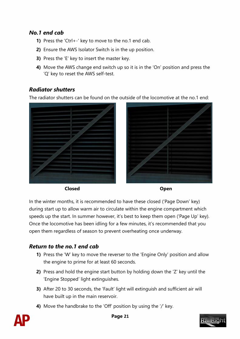
Radiator shutters
The radiator shutters can be found on the outside of the locomotive at the no.1 end:
Closed Open
In the winter months, it is recommended to have these closed (‘Page Down’ key)
during start up to allow warm air to circulate within the engine compartment which
speeds up the start. In summer however, it’s best to keep them open (‘Page Up’ key).
Once the locomotive has been idling for a few minutes, it’s recommended that you
open them regardless of season to prevent overheating once underway.
Return to the no.1 end cab
1) Press the ‘W’ key to move the reverser to the ‘Engine Only’ position and allow
the engine to prime for at least 60 seconds.
2) Press and hold the engine start button by holding down the ‘Z’ key until the
‘Engine Stopped’ light extinguishes.
3) After 20 to 30 seconds, the ‘Fault’ light will extinguish and sufficient air will
have built up in the main reservoir.
4) Move the handbrake to the ‘Off’ position by using the ‘/’ key.
Page 22
Preparing the locomotive
Trailing cab
Please follow these instructions in the opposite cab you intend to drive from:
1) Insert the master key by pressing the ‘E’ key. Please note that if the master key
is inserted in the other cab, you must remove it from there before inserting it
in this one. When removing it, the Reverser must be in the ‘Off’ position.
2) Ensure the locomotive straight air brake is fully released.
3) Ensure the train brake is in the ‘Shut Down’ position on a dual-braked
locomotive and ‘Running’ on a vacuum-only locomotive.
4) Ensure the AWS isolator switch is in the up position.
5) Ensure the AWS change end switch is in the ‘Off’ position.
6) If running light engine, turn the tail lights on using the ‘J’ key.
7) Remove the master key pressing the ‘E’ key.
Driving cab
Switch cabs and follow these final instructions:
1) Insert the master key by pressing the ‘E’ key.
2) Ensure the AWS isolator switch is in the up position.
3) Ensure the AWS change end switch is in the ‘On’ position.
4) Press the ‘Q’ key to reset the AWS self-test.
5) Turn the marker lights on.
6) Ensure the brake mode is correct for the duties you are about to undertake.
7) If the train brake handle is in the ‘Shut Down’ position, lift up the pin holding
it in place by holding the ‘R’ key and then at the same time, move the train
brake handle to the ‘Emergency’ position by pressing the ‘;’ key.
You should now be ready to move off. For information on how to do so, please see
the Driving guide section below.
Page 23
Driving guide
The following steps should allow you to drive the class 40 in a proper manner:
1) Move the reverser to your desired direction of travel by pressing either the ‘W’
key for forward or the ‘S’ key for reverse.
2) Apply some power by pressing the ‘A’ key until you reach the required tractive
effort to get your train on the move. At the same time, move the train brake
handle to the ‘release’ position. Please note that when using the vacuum
brakes, you can make the brakes release quicker by holding down the ‘;’ key
which speeds up the exhausters.
3) You may now increase power as you see fit, making sure to not place too
much stress on the traction motors as described in the Traction motor failure
section of this manual.
4) To brake the train using the dual train brake, you may make graduated
applications and releases by moving the handle between notches ‘running’
and ‘full service’. To brake the train using the vacuum train brake, simply move
the brake handle into the apply section which will apply at a quicker rate the
further you place it towards ‘Emergency’. When you have reached your
desired rate of braking, move the handle back to the ‘Running’ position which
will hold the brake application. To release the brake, you will need to move
the brake handle to the ‘Release’ position.
5) In the event of an emergency brake application, the locomotive will come to a
stop where you must do the following to release the brakes. Move the
reverser to ‘Neutral’, the power handle to ‘0%’, the train brake handle to
‘Emergency’ and then you should be able release the brakes.
Page 24
How to use in the scenario editor
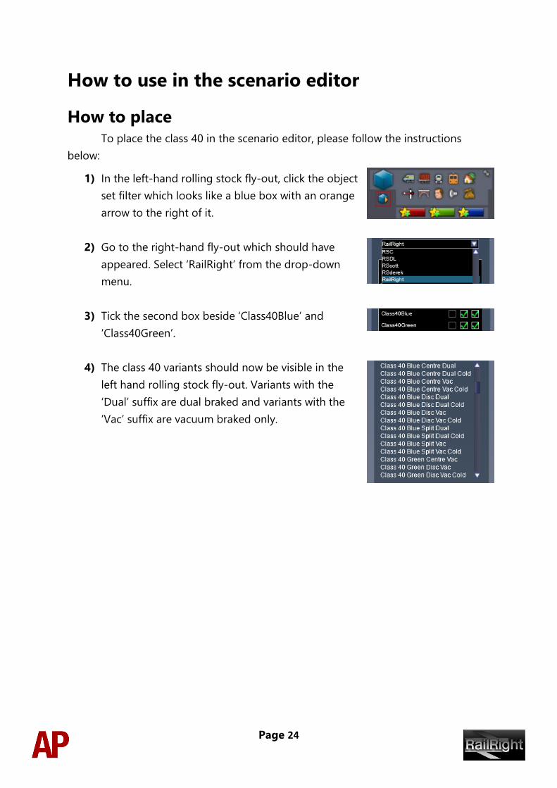
How to place
To place the class 40 in the scenario editor, please follow the instructions
below:
1) In the left-hand rolling stock fly-out, click the object
set filter which looks like a blue box with an orange
arrow to the right of it.
2) Go to the right-hand fly-out which should have
appeared. Select ‘RailRight’ from the drop-down
menu.
3) Tick the second box beside ‘Class40Blue’ and
‘Class40Green’.
4) The class 40 variants should now be visible in the
left hand rolling stock fly-out. Variants with the
‘Dual’ suffix are dual braked and variants with the
‘Vac’ suffix are vacuum braked only.
Page 25
Numbering When placing a class 40 in the scenario editor, you are able to control a
number of features via the dynamic number. Please see below for an explanation:
Class 40 Blue Split Dual & Centre Dual
Number format: ABCDE@@@@@####
A - Brake Mode Start Position 0 = AirGoods / 1 = AirPass / 2 =VacPass / 3
=VacGoods
B - 0 = Pre Tops numbering / 1 = Tops numbering
C - 0 = Headcode Letters / 1 = Headcode Dots
D - 0 = Red buffers / 1 = Black Buffers
E - 0 = frost grille / 1 = no frost grille
@@@@@ = 5 digit unit number (use the full TOPS number, eg. 40145)
#### = 4 digit headcode (number/letter/number/number for use with blinds)
Vacuum braked examples of the above are exactly the same apart from the removal of
the Brake Mode Start position option.
Class 40 Blue Disc Dual
Number format: ABCD@@@@@EFGH
A - Brake Mode Start Position 0 = AirGoods / 1 = AirPass / 2 =VacPass / 3
=VacGoods
B - 0 = Pre Tops numbering / 1 = Tops numbering
C - 0 = frost grille / 1 = no frost grille
D - 0 = Red buffers / 1 = Black Buffers
@@@@@ = 5 digit unit number (use the full TOPS number, eg. 40145)
E = Top Headcode Disc Start Position 0 = Up / 1 = Open / 2 =Closed
F = Right Headcode Disc Start Position 0 = Up / 1 = Open / 2 =Closed
G = Centre Headcode Disc Start Position 0 = Up / 1 = Open / 2 =Closed
H = Left Headcode Disc Start Position 0 = Up / 1 = Open / 2 =Closed
Vacuum braked examples of the above are exactly the same apart from the removal of
the Brake Mode Start Position option.
Class 40 Green – Split & Centre
Number format: A@@@####
A – Yellow Warning panel 0 = Full Green / 1 = Half Yellows / 2 = Full Yellows
@@@ = 3 digit unit number (Use the Pre TOPS number, e.g. 335)
#### = 4 digit headcode (number/letter/number/number for use with blinds)
Page 26
Class 40 Green – Disc
Number format: A@@@BCDE
A – Yellow Warning panel 0 = Full Green / 1 = Half Yellows / 2 = Full Yellows
@@@ = 3 digit unit number (Use the Pre TOPS number, e.g. 335)
B = Top Headcode Disc Start Position 0 = Up / 1 = Open / 2 =Closed
C = Right Headcode Disc Start Position 0 = Up / 1 = Open / 2 =Closed
D = Centre Headcode Disc Start Position 0 = Up / 1 = Open / 2 =Closed
E = Left Headcode Disc Start Position 0 = Up / 1 = Open / 2 =Closed
Please note, if you wish to change the actual number of the locomotive such as
‘40152’ or ‘D204’, the number must be correct to the variant you are using.
Please see the ‘Appendix’ at the end of this manual for a list of numbers and
their corresponding variant.
Scenarios
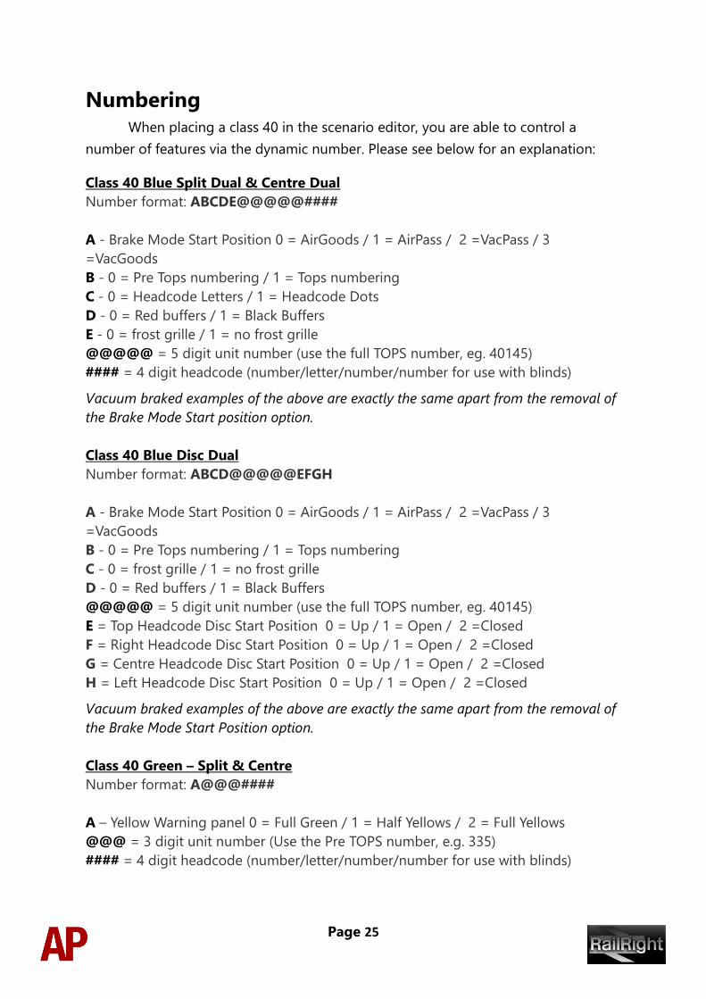
APC40: 1A41 17:00 Edinburgh Waverley - Aberdeen
Route = Just Trains - Scottish ECML
Track covered = Edinburgh Waverley - Dundee
Traction = BR Blue 40057
Year = 1980
Duration = 1 hour 25 minutes
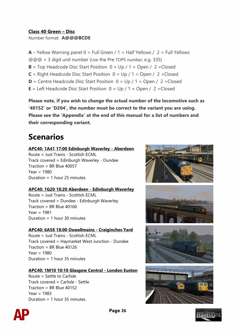
APC40: 1G20 18:20 Aberdeen - Edinburgh Waverley
Route = Just Trains - Scottish ECML
Track covered = Dundee - Edinburgh Waverley
Traction = BR Blue 40160
Year = 1981
Duration = 1 hour 30 minutes
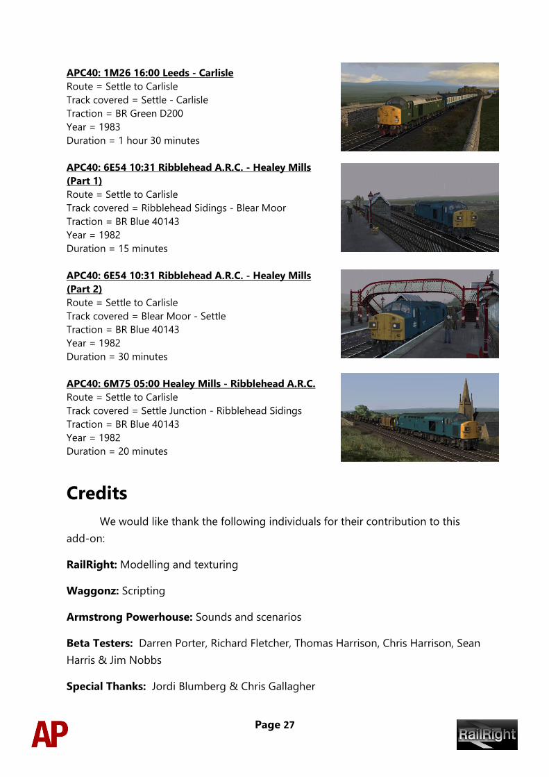
APC40: 6A58 18:00 Oxwellmains - Craiginches Yard
Route = Just Trains - Scottish ECML
Track covered = Haymarket West Junction - Dundee
Traction = BR Blue 40126
Year = 1980
Duration = 1 hour 35 minutes
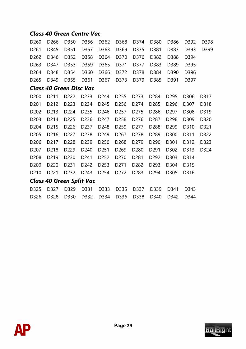
APC40: 1M10 10:10 Glasgow Central - London Euston
Route = Settle to Carlisle
Track covered = Carlisle - Settle
Traction = BR Blue 40152
Year = 1983
Duration = 1 hour 35 minutes
Page 27
APC40: 1M26 16:00 Leeds - Carlisle
Route = Settle to Carlisle
Track covered = Settle - Carlisle
Traction = BR Green D200
Year = 1983
Duration = 1 hour 30 minutes
APC40: 6E54 10:31 Ribblehead A.R.C. - Healey Mills
(Part 1)
Route = Settle to Carlisle
Track covered = Ribblehead Sidings - Blear Moor
Traction = BR Blue 40143
Year = 1982
Duration = 15 minutes
APC40: 6E54 10:31 Ribblehead A.R.C. - Healey Mills
(Part 2)
Route = Settle to Carlisle
Track covered = Blear Moor - Settle
Traction = BR Blue 40143
Year = 1982
Duration = 30 minutes
APC40: 6M75 05:00 Healey Mills - Ribblehead A.R.C.
Route = Settle to Carlisle
Track covered = Settle Junction - Ribblehead Sidings
Traction = BR Blue 40143
Year = 1982
Duration = 20 minutes
Credits
We would like thank the following individuals for their contribution to this
add-on:
RailRight: Modelling and texturing
Waggonz: Scripting
Armstrong Powerhouse: Sounds and scenarios
Beta Testers: Darren Porter, Richard Fletcher, Thomas Harrison, Chris Harrison, Sean
Harris & Jim Nobbs
Special Thanks: Jordi Blumberg & Chris Gallagher

Page 28
Appendix
Numbers and their corresponding variant
Class 40 Blue Centre Dual
40060
40061
40063
40064
40066
40145
40146
40147
40149
40150
40151
40152
40153
40154
40155
40157
40158
40159
40160
40162
40163
40164
40165
40166
40167
40168
40169
40170
40171
40172
40174
40176
40177
40178
40180
40181
40182
40185
40186
40188
40189
40190
40191
40192
40193
40194
40195
40196
40197
40199
Class 40 Blue Centre Vac
40062
40065
40148
40156
40161
40173
40175
40179
40183
40184
40187
40198
Class 40 Blue Disc Dual
40001
40002
40004
40005
40006
40007
40012
40013
40014
40015
40016
40021
40022
40024
40027
40028
40029
40030
40033
40034
40035
40038
40039
40041
40043
40044
40045
40047
40048
40050
40051
40052
40053
40054
40055
40056
40057
40058
40059
40067
40068
40069
40071
40072
40073
40074
40076
40077
40078
40079
40080
40081
40082
40083
40084
40085
40086
40089
40090
40091
40093
40095
40096
40097
40098
40099
40100
40102
40104
40110
40111
40113
40117
40118
40119
40122
40124
Class 40 Blue Disc Vac
40003
40008
40009
40010
40011
40017
40018
40019
40020
40023
40025
40026
40031
40032
40036
40037
40040
40042
40046
40049
40070
40075
40087
40088
40092
40094
40101
40103
40105
40106
40107
40108
40109
40112
40114
40115
40116
40120
40121
40123
Class 40 Blue Split Dual
40126
40127
40128
40129
40130
40131
40132
40133
40134
40135
40136
40137
40140
40141
40143
Class 40 Blue Split Vac
40125 40138 40139 40142 40144
Page 29
Class 40 Green Centre Vac
D260
D261
D262
D263
D264
D265
D266
D345
D346
D347
D348
D349
D350
D351
D352
D353
D354
D355
D356
D357
D358
D359
D360
D361
D362
D363
D364
D365
D366
D367
D368
D369
D370
D371
D372
D373
D374
D375
D376
D377
D378
D379
D380
D381
D382
D383
D384
D385
D386
D387
D388
D389
D390
D391
D392
D393
D394
D395
D396
D397
D398
D399
Class 40 Green Disc Vac
D200
D201
D202
D203
D204
D205
D206
D207
D208
D209
D210
D211
D212
D213
D214
D215
D216
D217
D218
D219
D220
D221
D222
D223
D224
D225
D226
D227
D228
D229
D230
D231
D232
D233
D234
D235
D236
D237
D238
D239
D240
D241
D242
D243
D244
D245
D246
D247
D248
D249
D250
D251
D252
D253
D254
D255
D256
D257
D258
D259
D267
D268
D269
D270
D271
D272
D273
D274
D275
D276
D277
D278
D279
D280
D281
D282
D283
D284
D285
D286
D287
D288
D289
D290
D291
D292
D293
D294
D295
D296
D297
D298
D299
D300
D301
D302
D303
D304
D305
D306
D307
D308
D309
D310
D311
D312
D313
D314
D315
D316
D317
D318
D319
D320
D321
D322
D323
D324
Class 40 Green Split Vac
D325
D326
D327
D328
D329
D330
D331
D332
D333
D334
D335
D336
D337
D338
D339
D340
D341
D342
D343
D344