class xi - cbsecbseacademic.nic.in/web_material/curriculum/vocational/2015/...i foundry technology-i...
TRANSCRIPT

i
Foundry Technology-I (Practical Manual)
Foundry Technology - IPractical Manual
Class XI
CENTRAL BOARD OF SECONDARY EDUCATION2, COMMUNITY CENTRE, PREET VIHAR, DELHI - 110092

ii
Foundry Technology-I (Practical Manual)
Foundry Technology - I Practical Manual
© CBSE, Delhi– 110301[Paper used : 80 GSM CBSE Watermark Maplitho Paper]
Print:
FIRST EDITION © CBSE, INDIA
Price : Rs. 140/-
This book or part thereof may not be reproduced by any person or Agency in any manner.
Published by : The Secretary, C. B. S. E., Shiksha Kendra, 2, Community Centre, Preet Vihar, Delhi-110301
Printed by : I G Printers Pvt. Ltd., New Delhi-110020
iii
Foundry Technology-I (Practical Manual)
ContentsExercise 1: 1
1.1. Safety norms of the foundry: 11.2. Introduction to foundry tools 101.3. Layout sketch of the foundry 15
Exercise 2. 172.1. Pattern layout 172.2. Locating of sprue, runner and riser 20
Exercise 3 223.1. Shape Evolution of sand particle 233.2. AFS Sieve analysis of sand 233.3 Tests for Moisture Content 253.4 Tests for Clay Content 253.5 Specimen Preparation for permeability test, hardness test, 26 strength test of sand mix3.6. Permeability Test 273.7. Sand Hardness Test 293.8. Sand Strength Test 293.9. Optimizations of binder and water content by variation of 32 binder and water level.
Exercise 4 : 34 Preparation of a green sand mold with a simple pattern, use of mold coating, Measurement of mold hardness

iv
Foundry Technology-I (Practical Manual)

v
Foundry Technology-I (Practical Manual)
PREFACE
The Indian Foundry (Metal Casting) Industry is 2nd largest globally. The industry growth in 2010-11 was more than 20% and employs approximately 500,000 people directly and another 1.5 Million indirectly.
Metal castings is the process of melting the metals of different specification and alloys and pouring in cavities (Molds) to give desired shapes of the final component as per required application.These components are ready to use either as it is or after machining as the case may be. Castings are made in various metallurgies such as grey iron, ductile iron, steel, aluminium and its alloys, zinc, magnesium and copper alloys etc. and then heat treated and machined as required as peruse and application of the component.
Government of India has ambitious plans to boost share of manufacturing in the GDP to 25% from present 15-16% , the industry is likely to be driven by huge demand from various industrial sectors which will create an additional demand for 200,000 -250,000 skilled workforce in foundry industry at various levels in next five years. The foundry industry is facing acute shortage of skilled manpower and this shortage is likely to compound in next 5 years.
To address the need of skilled manpower across various industrial sectors, CBSE has undertaken the ambitious project of introducing competency based Vocational Education in its affiliated schools. Taking cue from this need, a new course on Foundry Technology is being launched in cooperation with the Institute of Indian Foundrymen (IIF) that will help students to either join the industry after Class XII or they can pursue higher education in this field.
The Board is grateful to the members of the Committee of Course for their advice, guidance and total commitment towards development of this course. We are indeed indebted to these academic advisors who have lent us the benefit of their rich and insightful experience. I would like to appreciate Vocational Education Cell, CBSE; for coordinating and successfully completing the work.
Vineet JoshiChairman, CBSE

vi
Foundry Technology-I (Practical Manual)

vii
Foundry Technology-I (Practical Manual)
Acknowledgements
Advisors:
1. Sh. Vineet Joshi, IAS, Chairman, CBSE.
2. Sh. M.V.V. Prasada Rao, Director (Vocational and EDUSAT), CBSE.
Editing & Coordination:
1. Dr. Biswajit Saha, Associate Professor & Programme Officer, (Vocational Education), CBSE.
2. Ms. Swati Gupta, Assistant Professor & Assistant Programme Officer, (Vocational Education), CBSE.
Material Production Group:
1. Dr. Amitesh Kumar, Asstt. Prof., Deptt. of Foundry Tech., Ranchi-Convener.
2. Dr. Arasu Mani, Associate Prof., PSG College Coimbatore, Chennai.
3. Dr. K.K. Singh, Asstt. Prof., Deptt. of Foundry Tech., Ranchi.
4. Dr. A. K. Singh, Professor., Deptt. of Foundry Tech., Ranchi.

viii
Foundry Technology-I (Practical Manual)
ix
Foundry Technology-I (Practical Manual)
x
Foundry Technology-I (Practical Manual)
THE CONSTITUTION OF INDIAPREAMBLE
1WE, THE PEOPLE OF INDIA, having solemnly resolved to constitute India into a SOVEREIGN SOCIALIST SECULAR DEMOCRATIC REPUBLIC and to secure to all its citizens :
JUSTICE, social, economic and political;
LIBERTY of thought, expression, belief, faith and worship;
EQUALITY of status and of opportunity; and to promote among them all 2FRATERNITY assuring the dignity of the individual and the unity and integrity of the Nation;
IN OUR CONSTITUENT ASSEMBLY this twenty-sixth day of November, 1949, do HEREBY ADOPT, ENACT AND GIVE TO OURSELVES THIS CONSTITUTION.
THE CONSTITUTION OF INDIAChapter IV A
FUNDAMENTAL DUTIES
ARTICLE 51A
Fundamental Duties - It shall be the duty of every citizen of India-
(a) to abide by the Constitution and respect its ideals and institutions, the National Flag and the National Anthem;
(b) to cherish and follow the noble ideals which inspired our national struggle for freedom;
(c) to uphold and protect the sovereignty, unity and integrity of India;
(d) to defend the country and render national service when called upon to do so;
(e) to promote harmony and the spirit of common brotherhood amongst all the people of India transcending religious, linguistic and regional or sectional diversities; to renounce practices derogatory to the dignity of women;
(f) to value and preserve the rich heritage of our composite culture;
(g) to protect and improve the natural environment including forests, lakes, rivers, wild life and to have compassion for living creatures;
(h) to develop the scientific temper, humanism and the spirit of inquiry and reform;
(i) to safeguard public property and to abjure violence;
(j) to strive towards excellence in all spheres of individual and collective activity so that the nation constantly rises to higher levels of endeavour and achievement;
1(k) to provide opportunities for education to his/her child or, as the case may be, ward between age of 6 and 14 years.
1. Subs, by the Constitution (Forty-Second Amendment) Act. 1976, sec. 2, for "Sovereign Democratic Republic” (w.e.f. 3.1.1977)
2. Subs, by the Constitution (Forty-Second Amendment) Act. 1976, sec. 2, for "unity of the Nation” (w.e.f. 3.1.1977)
1. Subs, by the Constitution (Eighty-Sixth Amendment) Act. 2002.
xi
Foundry Technology-I (Practical Manual)
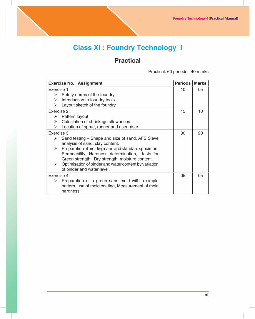
Class XI : Foundry Technology I
Practical
Practical: 60 periods, 40 marks
Exercise No. Assignment Periods MarksExercise 1. Safety norms of the foundry Introduction to foundry tools Layout sketch of the foundry
10 05
Exercise 2. Pattern layout Calculation of shrinkage allowances Location of sprue, runner and riser, riser
15 10
Exercise 3 Sand testing – Shape and size of sand, AFS Sieve
analysis of sand, clay content. Preparation of molding sand and standard specimen,
Permeability, Hardness determination, tests for Green strength, Dry strength, moisture content.
Optimisation of binder and water content by variation of binder and water level.
30 20
Exercise 4 Preparation of a green sand mold with a simple
pattern, use of mold coating, Measurement of mold hardness
05 05
THE CONSTITUTION OF INDIAPREAMBLE
1WE, THE PEOPLE OF INDIA, having solemnly resolved to constitute India into a SOVEREIGN SOCIALIST SECULAR DEMOCRATIC REPUBLIC and to secure to all its citizens :
JUSTICE, social, economic and political;
LIBERTY of thought, expression, belief, faith and worship;
EQUALITY of status and of opportunity; and to promote among them all 2FRATERNITY assuring the dignity of the individual and the unity and integrity of the Nation;
IN OUR CONSTITUENT ASSEMBLY this twenty-sixth day of November, 1949, do HEREBY ADOPT, ENACT AND GIVE TO OURSELVES THIS CONSTITUTION.
THE CONSTITUTION OF INDIAChapter IV A
FUNDAMENTAL DUTIES
ARTICLE 51A
Fundamental Duties - It shall be the duty of every citizen of India-
(a) to abide by the Constitution and respect its ideals and institutions, the National Flag and the National Anthem;
(b) to cherish and follow the noble ideals which inspired our national struggle for freedom;
(c) to uphold and protect the sovereignty, unity and integrity of India;
(d) to defend the country and render national service when called upon to do so;
(e) to promote harmony and the spirit of common brotherhood amongst all the people of India transcending religious, linguistic and regional or sectional diversities; to renounce practices derogatory to the dignity of women;
(f) to value and preserve the rich heritage of our composite culture;
(g) to protect and improve the natural environment including forests, lakes, rivers, wild life and to have compassion for living creatures;
(h) to develop the scientific temper, humanism and the spirit of inquiry and reform;
(i) to safeguard public property and to abjure violence;
(j) to strive towards excellence in all spheres of individual and collective activity so that the nation constantly rises to higher levels of endeavour and achievement;
1(k) to provide opportunities for education to his/her child or, as the case may be, ward between age of 6 and 14 years.
1. Subs, by the Constitution (Forty-Second Amendment) Act. 1976, sec. 2, for "Sovereign Democratic Republic” (w.e.f. 3.1.1977)
2. Subs, by the Constitution (Forty-Second Amendment) Act. 1976, sec. 2, for "unity of the Nation” (w.e.f. 3.1.1977)
1. Subs, by the Constitution (Eighty-Sixth Amendment) Act. 2002.
xii
Foundry Technology-I (Practical Manual)
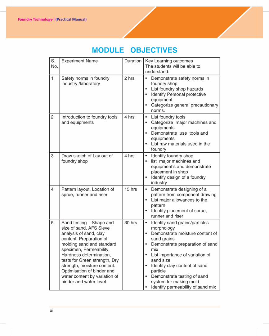
MODULE OBJECTIVESS. No.
Experiment Name Duration Key Learning outcomes The students will be able to understand:
1 Safety norms in foundry industry /laboratory
2 hrs • Demonstrate safety norms in foundry shop
• List foundry shop hazards • Identify Personal protective
equipment • Categorize general precautionary
norms.2 Introduction to foundry tools
and equipments4 hrs • List foundry tools
• Categorize major machines and equipments
• Demonstrate use tools and equipments
• List raw materials used in the foundry
3 Draw sketch of Lay out of foundry shop
4 hrs • Identify foundry shop• list major machines and
equipment’s and demonstrate placement in shop
• Identify design of a foundry industry
4 Pattern layout, Location of sprue, runner and riser
15 hrs • Demonstrate designing of a pattern from component drawing
• List major allowances to the pattern
• Identify placement of sprue, runner and riser
5 Sand testing – Shape and size of sand, AFS Sieve analysis of sand, clay content. Preparation of molding sand and standard specimen, Permeability, Hardness determination, tests for Green strength, Dry strength, moisture content. Optimisation of binder and water content by variation of binder and water level.
30 hrs • Identify sand grains/particles morphology
• Demonstrate moisture content of sand grains
• Demonstrate preparation of sand mix
• List importance of variation of sand size
• Identify clay content of sand particle
• Demonstrate testing of sand system for making mold
• Identify permeability of sand mix
xiii
Foundry Technology-I (Practical Manual)
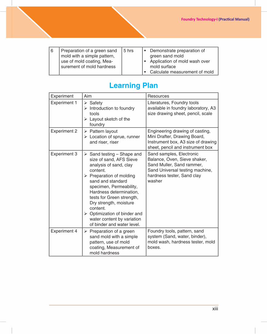
6 Preparation of a green sand mold with a simple pattern, use of mold coating, Mea-surement of mold hardness
5 hrs • Demonstrate preparation of green sand mold
• Application of mold wash over mold surface
• Calculate measurement of mold
Learning PlanExperiment Aim ResourcesExperiment 1 Safety
Introduction to foundry tools
Layout sketch of the foundry
Literatures, Foundry tools available in foundry laboratory, A3 size drawing sheet, pencil, scale
Experiment 2 Pattern layout Location of sprue, runner
and riser, riser
Engineering drawing of casting, Mini Drafter, Drawing Board, Instrument box, A3 size of drawing sheet, pencil and instrument box
Experiment 3 Sand testing – Shape and size of sand, AFS Sieve analysis of sand, clay content.
Preparation of molding sand and standard specimen, Permeability, Hardness determination, tests for Green strength, Dry strength, moisture content.
Optimization of binder and water content by variation of binder and water level.
Sand samples, Electronic Balance, Oven, Sieve shaker, Sand Muller, Sand rammer, Sand Universal testing machine, hardness tester, Sand clay washer
Experiment 4 Preparation of a green sand mold with a simple pattern, use of mold coating, Measurement of mold hardness
Foundry tools, pattern, sand system (Sand, water, binder), mold wash, hardness tester, mold boxes.

xiv
Foundry Technology-I (Practical Manual)
1
Foundry Technology-I (Practical Manual)
ExErcisE 1
Experiment: 1.1Title : Safety norms in foundry industry/laboratory
introduction:Objective: To recognize the importance of safety in a foundry and execute proper safety measures in carrying out casting processes.
resource Material:1. Principles of Foundry Technology By P. L. Jain2. http://www.youtube.com/watch?v=4t2ddeJECZ83. www.rotblattsculpture.com/Articles/safety.htmlhttp://www.youtube.com/
watch?v=v4i2INpJnVM4. http://www.rotblattsculpture.com/Articles/safety.html5. http://www.homemodelenginemachinist.com/f36/15-hot-work-safety-rules-
foundry-14397/6. http://chestofbooks.com/crafts/machinery/Shop-Practice-V2/Safety-in-
Foundry.html#.UPOUUfJ0rFw7. http://www.astmnewsroom.org/default.aspx?pageid=976
Delivery schedule: 02 hrs
student expectations/learning objective: • Demonstratesafetynormsinfoundryshop• Listfoundryshophazards• IdentifyPersonalprotectiveequipment• Categorizegeneralprecautionarynorms.
Pre-learning required: Introduction to foundry.
Handouts/material required/equipment’s & tools: Paper sheet and pen to note down the instruction.
Procedure/methodology:
A. safety norms of the foundry:Purpose
The purpose of this compliance code is to provide practical guidance on how employers who undertake foundry work can meet their duties under the Occupational Health and Safety Act 2004 (the OHS Act) and Occupational Health and Safety Regulations 2007 (the Regulations).

2
Foundry Technology-I (Practical Manual)
scope
This code covers foundry work that predominantly involves the casting of molten metal into a mold. It can be done manually (static casting) or automatically (injection, die or continuous casting). A typical process includes preparing a mold casting, melting and pouringmetalintothemold,andremovingandfinishingthecasting.
Because of the diverse and hazardous nature of the work environment, foundries present a range of risks, including:
• explosionandburnsfrommoltenmetal• respiratorydisordersfromexposuretogases,vapours,fumesanddusts• effectsonskinfromcontactwithcorrosivechemicals• eyeinjuriesfromlightradiation,metalfragmentsorchemicalsplashes• heatstress,heatstrokeandfatiguefromhotworkingconditions• slips,tripsandfalls• jointandmusclesprainsandstrains• mechanicalhazardsfrommachineryandequipment(suchasentanglementor
crushing)• non-mechanicalhazardsfrommachineryandequipment(suchasvibrationand
noise).
Thecodeprovidespracticalguidanceonfoundryspecifichazardsbutalsoreferstoother hazards related to foundry work. Risk controls set out in the code are considered to be a means of meeting a duty holder’s obligations so far as is reasonably practicable. If the risk controls are not appropriate to the particular circumstances in a foundry, a dutyholderisexpectedtoimplementequallyeffectivecontrols.
B. Foundry hazards :Molten metal explosions
Steam explosions are caused by the introduction of moisture into molten metal.
chemical explosions
Chemical explosions occur through the introduction of reactive chemical substances to molten metal directly or as a contaminant in charge material.
Heat stress
Working in hot conditions is hazardous. Health effects range from discomfort or heat rash to heat exhaustion or heat stroke resulting in permanent damage or death. Heat stress can harm without the worker being aware of the degree of effect until it is almost too late. It affects concentration, perception and decision making, so heat stress is also dangerous in less obvious ways.
Burns
Burns are one of the major types of injuries in molten metal foundries and are generally caused by contact with hot surfaces, radiation or molten metal splashing.
3
Foundry Technology-I (Practical Manual)
Light radiation
Eye disorders and skin burns may be caused by intense ultraviolet and infrared radiation from molten metal in furnaces, particularly around pouring areas and in welding operations. Bystanders and passersby also need to be protected, preferably by exclusion.
Hazardous substances
Hazardous substances such as lead, amines, formaldehyde, toluene, phenol, furfuryl alcohol and isocyanates are substances that can harm the health of people exposed to them. They can be inhaled, swallowed or absorbed through the skin, and employees can suffer immediate or long-term health effects.
Exposure may cause irritation, chemical burns, cancer, birth defects or diseases of certain organs such as the lungs, liver, kidneys and nervous system.
Hazardous wastes
Legislative controls exist for the safe transport, storage and disposal of hazardous waste. Where no legislative controls apply, a safe means of transport and disposal (having regard to the nature of the hazard) needs to be employed (eg sealed, marked containers suitably protected from possible damage and able to be handled safely).
Dangerous goods
Dangerous goods such as carbon dioxide, formaldehyde, oxygen, sulphur dioxide andxylenearehazardousforavarietyofreasons–theymaybehighlyflammable,explosive, corrosive, acutely toxic, asphyxiant or highly reactive according to class. Theyarereadilyidentifiablebyclassdiamondsonthelabels.
slips, trips and falls
Slips, tripsandfallsareacommonhazard inmostworkplaces,withconsequencesranging from mild (such as scrapes) to severe (such as fractures or fatalities).
Manual handling
Manual handling tasks are those where force is exerted by a person to lift, lower, push, pull, carry or otherwise move, hold or restrain any object. These occur during pattern and core making, loading furnaces, molding, fettling, dispatch, inspection and surface coating.
Machinery and equipment (plant)
Machineryandequipmentareused inpatternandcoremakingaswell as castingand molding. Plant such as cranes, hoists, forklifts and conveyors are also used as mechanical handling devices within foundries.
Mechanical hazards
Mechanical hazards include hard surfaces coming together and scissoring action. Risks include entanglement, crushing, severing, cutting and slips, trips and falls.
4
Foundry Technology-I (Practical Manual)
c. Non-mechanical hazardsNoise
Noise levels in excess of 85 decibels (dB(A)) averaged over eight hours, or a C weighted peak hold sound pressure reading of 140 dB(C) can result in hearing loss. Pattern and core making, molding, knockout and cleaning operations, fettling and some furnaces areamongtheequipmentandprocessesthatproducenoiselevelsinexcessoftheacceptable standard. Regular exposure to excessive noise can damage the inner ear andcausetinnitusleadingtodifficultiesincommunications.
Vibration
Whole body (1–80 Hz) vibration takes place during shake out, sand-slinging, on forklifts, cranes and during pneumatic ramming operations. The adverse effects of whole body vibration include increased blood pressure and heart problems, nervous disorders, stomach problems as well as joint and spine injuries.
Electricity
Electric shock causes injury or death. A shock can be received through direct contact with live parts, through contact with a medium such as an unearthed tool or when it arcs across a gap. The risk is increased by excessive sweating, as wet skin is more conductive than dry skin.
Machinery that may cause non-mechanical injury
Abrasive blasting and rumbling present hazards to employees from airborne contaminants and noise.
Access hazards
Access hazards are often complex, involving several risks at the same time, such as chemicaldosinginconfinedspacesorworkingatheight.
D. Personal protective equipment (PPE) in the foundry•Primaryprotective clothing is used for specifichazardous tasks then removed. Itprovides protection from hazards such as metal splash and radiant heat. The garments need to be made from inherently fire-retardant fabrics to ensure their protectiveproperties are intact as long as the garment is intact. They need to be comfortable to wear and breathable in very extreme work conditions. Leather options offer some durabilityandprotectivebenefitsbutcancompromisecomfortandaddtoheatstressin certain situations.
•Secondaryprotectiveclothingisall-day/everydayclothing.Theclothingneedstobefire-retardantandthechoiceofinherentortreatedcantakecomfortandcostintoaccount, but these garments are the last defence for the body if primary protection fails.Acottonfabricistheminimumrequirement,butspeciallytreatedcottonorwoolfabric is recommended

5
Foundry Technology-I (Practical Manual)
Primary and secondary PPE
Primary PPE secondary PPEfor molten metal work(in addition to secondary PPE)
for general foundry work
HEADUse helmets where there is potential for items to fall from height or where work takes place above head height (eg on a mezzanine). Industrial safety helmets should be considered. Where tasks result in dust or particulates, a head covering should be considered.EArsThe factors that need to be taken into account when selecting hearing protectors need to include compliance with AS 1270, level of noise, the wearer (eg personal characteristics, comfort), communication requirements, and compatibilitywith thejob/workplace. Guidance on hearing protectors is provided in AS/NZS 1269.3.
EYEs AND FAcEFace shields with neck protection.
EYEs AND FAcEIndustrial safety glasses with side shields are the minimum.
rEsPirATOrYRespiratory protective devices (RPD) used need to comply with AS/NZS 1716. The type of respirator selected needs to take into account the operator (ie facial hair, physiological and psychological factors), the task (ie how the job is done, duration, frequency)andthesubstance(ietypeofcontaminant,concentration).ThestandardAS/NZS 1715 provides guidance on the selection, use and maintenance of respira-tory protective devices. Guidance can also be obtained from suppliers of respiratory protectiveequipment.
6
Foundry Technology-I (Practical Manual)
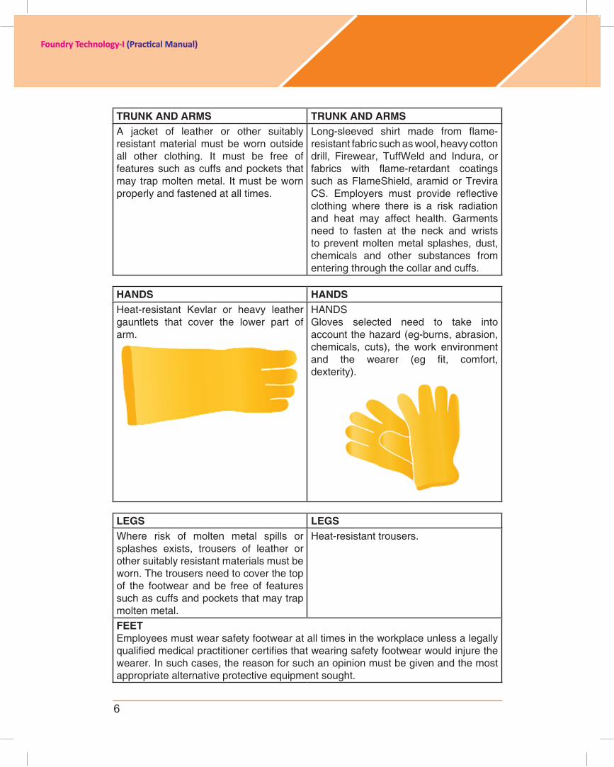
TrUNK AND ArMs TrUNK AND ArMsA jacket of leather or other suitably resistant material must be worn outside all other clothing. It must be free of features such as cuffs and pockets that may trap molten metal. It must be worn properly and fastened at all times.
Long-sleeved shirt made from flame-resistant fabric such as wool, heavy cotton drill, Firewear, TuffWeld and Indura, or fabrics with flame-retardant coatingssuch as FlameShield, aramid or Trevira CS. Employers must provide reflectiveclothing where there is a risk radiation and heat may affect health. Garments need to fasten at the neck and wrists to prevent molten metal splashes, dust, chemicals and other substances from entering through the collar and cuffs.
HANDs HANDsHeat-resistant Kevlar or heavy leather gauntlets that cover the lower part of arm.
HANDSGloves selected need to take into account the hazard (eg-burns, abrasion, chemicals, cuts), the work environment and the wearer (eg fit, comfort,dexterity).
LEGs LEGsWhere risk of molten metal spills or splashes exists, trousers of leather or other suitably resistant materials must be worn. The trousers need to cover the top of the footwear and be free of features such as cuffs and pockets that may trap molten metal.
Heat-resistant trousers.
FEETEmployees must wear safety footwear at all times in the workplace unless a legally qualifiedmedicalpractitionercertifiesthatwearingsafetyfootwearwouldinjurethewearer. In such cases, the reason for such an opinion must be given and the most appropriatealternativeprotectiveequipmentsought.

7
Foundry Technology-I (Practical Manual)
PPE commonly used in foundry; from left to right: heat resistant glove, safety shoe, leather apron, faces shields.
storage and care of protective equipmentFor foundry purposes, compliance is demonstrated by employers ensuring that:
• allprotectiveequipmentandclothingprovidedismaintainedinsoundcondition,tested routinely and capable of performing the protective functions for which it was provided.
• employeesaretrainedintheneedfor,effectiveuseandcareof,andmeansoftestingthefitofprotectiveequipment(whentrainedemployeesmustcooperateinthecareandmaintenanceoftheequipment).
• equipmentandclothingisonlywornbytheemployeetowhomitwasissued,andis marked with the name of that employee.
• cleanstorageisprovidedforallprotectiveequipmentandclothing.• maintenanceofclothingandequipmentisconductedwhenrequired.
Primary protective clothing the manner prescribed by the manufacturer or supplier.(Molten metal work)
Secondary protective clothing(General foundry work)
E. Following safety norms of foundry must be followed:• Alwayswearsafetyglasses,orfaceshieldsdesignedforthetypeofthework
operating any machine • Wearsafetyshoesifheavyworkisbeingdone.

8
Foundry Technology-I (Practical Manual)
• Wearclothingsuitedforthejob,wearshoeswiththicksoles.• Don’twearrings,watches,braceletsorotherjewelerythatcouldgetcaughtin
moving machinery.• Don’twearnecktiesorlooseturnclothingofanykind.• Wearshirtsorupperswithsleevescutofforrolledabovetheelbows.• Always remove gloves before turning on or operating amachine. Ifmaterial
is rough and sharp then gloves must be of work place or handle material with machine turned off.
• Keeping floor free of oil, grease or any other liquid. Clean up spilled liquidimmediately they are sleeping hazards.
• Aisleshouldbeclear,atalltimetoavoidtrippingofotheraccident.• Storematerialsinsuchawaythattheycannotbecometrippinghazards.• Don’tleavetoolsorworkonthetableofamachineevenifthemachineinnot
turning. Tools or work may fall off and cause an injury.• Puttoolsalwayswhennotinuse.• Placethescrapbox.• EventraceamountsofMoistureandMoltenMetaldon’tmix!!!Steamexplosions
are the cause of death in foundries. • Wear safety gear!! This includes, but is not limited to, leather shoes, leather
apron, proper gloves, wire mesh face shield, safety glasses and a helmet. A leather foundry hat is the best choice.
• HaveaDRYpileofsandandashovelreadytoputoutfiresortocontrolmetalspills.NEVERputwateronametalfire.ThiscancauseaHUGHEXPLOSION!
• Haveasandbedunderallareas.Thesandbedshouldbeatleast3inchesthick.Thiswillhelpincontainingmetalspillsandwillhelpprotectflooring.
• Neverpouroverwetground.Remember,evenTRACEAMOUNTSofMOISTUREcancauseEXPLOSIONS.
• Moltenmetalspilledonconcretewillcausetheconcretetoexplode.Useathicksand bed over concrete.
• Alwaysusecleanmetalasfeedstock.Combustionresiduesfromsomelubricantsand paints can be very toxic.
• Alwaysoperateinawellventilatedarea.Fumesanddustsfromcombustionandother foundry chemicals, processes and metals can be toxic.
• Alwaysuseadustmask.Dustsfromsand,partingdustsandchemicalscanbehazardousorcancercausing.Protectyourlungs!
• Alwaysusesafetyglasses.Evenminormishapscancauseblindness.• Neveruseacruciblethathasbeendamagedordropped.It’sjustnotworththe
risk. Imagine what would happen if a white hot crucible of brass crumbled as you werecarryingit!
• Always charge crucibles when cold. Addingmetal to a hot crucible is reallydangerous. If there is moisture on the metal, even just a haze, the metal can cause the entire contents of the crucible to explode.
• Spilledmoltenmetal can travel foragreatdistance.Operate ina clearworkarea.
• Thinkaboutwhatyouaredoingatalltimes.Focusonthejobathandandthenext step. Have all moves planned and rehearsed prior to any operation.
9
Foundry Technology-I (Practical Manual)
Educate yourself beforehand and always be careful of your own and bystander safety
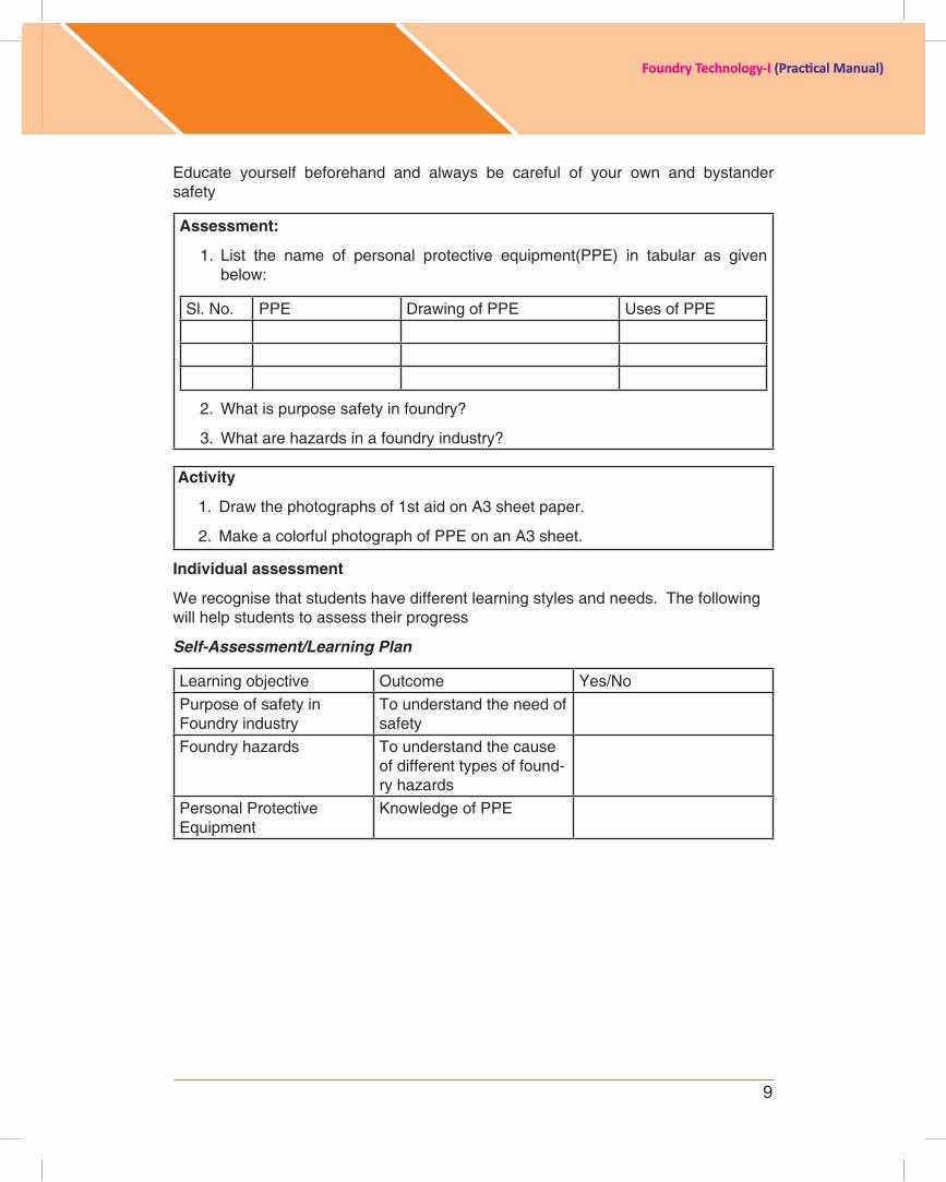
Assessment:
1. List the name of personal protective equipment(PPE) in tabular as givenbelow:
Sl. No. PPE Drawing of PPE Uses of PPE
2. What is purpose safety in foundry?
3. What are hazards in a foundry industry?
Activity
1. Draw the photographs of 1st aid on A3 sheet paper.
2. Make a colorful photograph of PPE on an A3 sheet.
individual assessment
We recognise that students have different learning styles and needs. The following will help students to assess their progress
Self-Assessment/Learning Plan
Learning objective Outcome Yes/NoPurpose of safety in Foundry industry
To understand the need of safety
Foundry hazards To understand the cause of different types of found-ry hazards
Personal Protective Equipment
Knowledge of PPE

10
Foundry Technology-I (Practical Manual)
Experiment: 1.2Title :Introductiontofoundrytoolsandequipments
introduction:Objective: Each student should get introduced with foundry tools and make a report on the list of foundry tools, their drawing and uses in foundry.
resource Material:1. Principles of Foundry Technology By P. L. Jain. 2. Introduction To Basic Manufacturing Process & Workshop Technology, By
Rajender Singh, New Age International Publisher, 1st addition - 2006.3. ht tp: / /www.scr ibd.com/doc/54115008/10/FOUNDRY-TOOLS-AND-
EQUIPMENTS4. http://www.themetalcasting.com/foundry-equipment.html5. http://www.technofabengineersjpr.com/foundry-equipment.htm
Delivery schedule: 4 hrs
student expectations/learning objective: • Listfoundrytools• Categorizemajormachinesandequipments• Demonstrateusetoolsandequipments• Listrawmaterialsusedinthefoundry
Pre-learning required: Safety measures of foundry.
Handouts/material required/equipment’s & tools: Paper sheet and pencil
Procedure/methodology:
Part A: introduction to foundry toolsStudents will be introduced by class teacher about the available foundry tools and equipments.
Student will take all tools.
They will draw the schematic sketch of tools against name of individual tool, its application in foundry process.
Some important tools used in foundry are given below:
1. showel: It consists of iron pan with a wooden handle. It can be used for mixing and conditioning the sand.

11
Foundry Technology-I (Practical Manual)
2. Trowels:Theseareusedforfinishingflatsurfacesandcomersinsideamold.Common shapes of trowels are shown as under. They are made of iron with a wooden handle.
3. Lifter: Alifterisafinishingtoolusedforrepairingthemoldandfinishingthemold sand. Lifter is also used for removing loose sand from mold.
4. Hand riddle: It is used for ridding of sand to remove foreign material from it. It consistsofawoodenframefittedwithascreenofstandardwiremeshat the bottom.
5.strike off bar:Itisaflatbar,madeofwoodorirontostrikeofftheexcesssandfrom the top of a box after ramming. Its one edge made beveled and the surface perfectly smooth and plane.
6. Vent wire: It is a thin steel rod or wire carrying a pointed edge at one end and a wooden handle or a bent loop at the other. After ramming and striking off the excess sand it is used to make small holes, called vents, in the sand mold to allow the exit of gases and steam during casting.
12
Foundry Technology-I (Practical Manual)
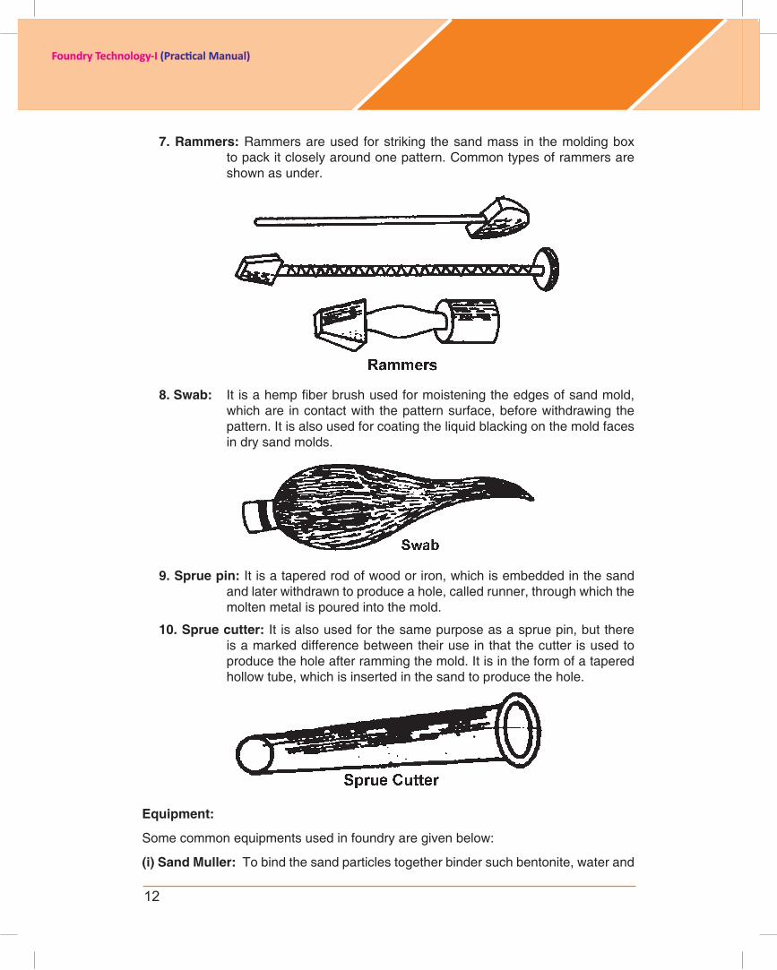
7. rammers: Rammers are used for striking the sand mass in the molding box to pack it closely around one pattern. Common types of rammers are shown as under.
8. swab: Itisahempfiberbrushusedformoisteningtheedgesofsandmold,which are in contact with the pattern surface, before withdrawing the pattern.Itisalsousedforcoatingtheliquidblackingonthemoldfacesin dry sand molds.
9. sprue pin: It is a tapered rod of wood or iron, which is embedded in the sand and later withdrawn to produce a hole, called runner, through which the molten metal is poured into the mold.
10. sprue cutter: It is also used for the same purpose as a sprue pin, but there is a marked difference between their use in that the cutter is used to produce the hole after ramming the mold. It is in the form of a tapered hollow tube, which is inserted in the sand to produce the hole.
Equipment:
Somecommonequipmentsusedinfoundryaregivenbelow:
(i) sand Muller: To bind the sand particles together binder such bentonite, water and
13
Foundry Technology-I (Practical Manual)
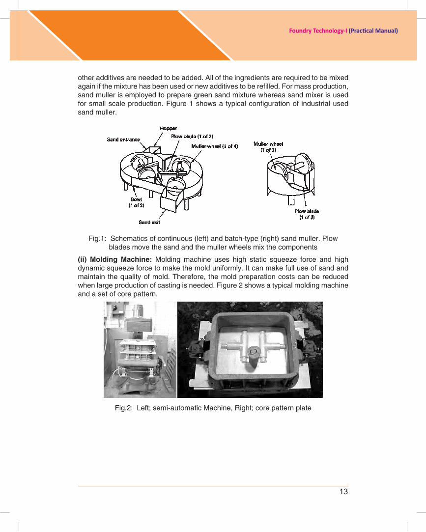
otheradditivesareneededtobeadded.Alloftheingredientsarerequiredtobemixedagainifthemixturehasbeenusedornewadditivestoberefilled.Formassproduction,sand muller is employed to prepare green sand mixture whereas sand mixer is used forsmallscaleproduction.Figure1showsatypicalconfigurationof industrialusedsand muller.
Fig.1: Schematics of continuous (left) and batch-type (right) sand muller. Plow blades move the sand and the muller wheels mix the components
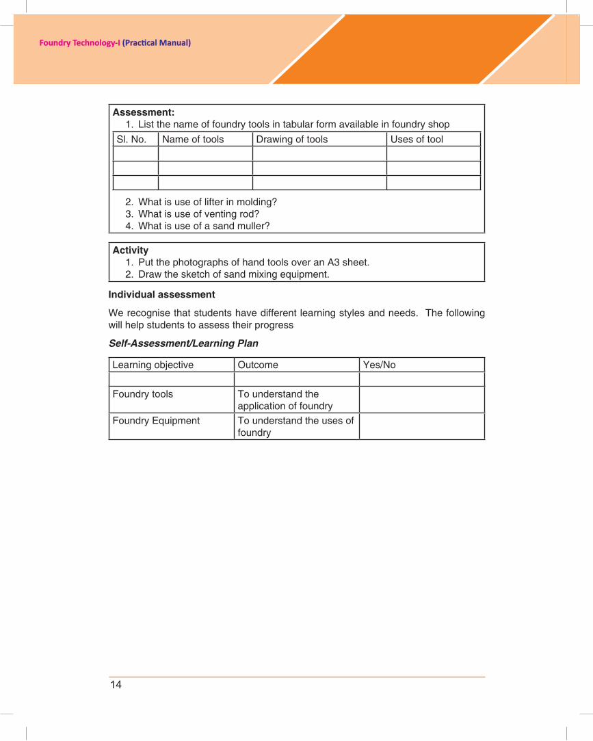
(ii) Molding Machine: Molding machine uses high static squeeze force and highdynamicsqueezeforcetomakethemolduniformly.Itcanmakefulluseofsandandmaintainthequalityofmold.Therefore,themoldpreparationcostscanbereducedwhen large production of casting is needed. Figure 2 shows a typical molding machine and a set of core pattern.
Fig.2: Left; semi-automatic Machine, Right; core pattern plate
14
Foundry Technology-I (Practical Manual)
Assessment:1. List the name of foundry tools in tabular form available in foundry shop
Sl. No. Name of tools Drawing of tools Uses of tool
2. What is use of lifter in molding?3. What is use of venting rod?4. What is use of a sand muller?
Activity1. Put the photographs of hand tools over an A3 sheet.2. Drawthesketchofsandmixingequipment.
individual assessment
We recognise that students have different learning styles and needs. The following will help students to assess their progress
Self-Assessment/Learning Plan
Learning objective Outcome Yes/No
Foundry tools To understand the application of foundry
FoundryEquipment To understand the uses of foundry
15
Foundry Technology-I (Practical Manual)
Experiment :1.3 Title : Draw sketch of Lay out of foundry shop
introduction:Objective: Student must have knowledge about the layout which includes placement ofequipment,differentshopfloorandentryofall inputstofinaldispatchoffinisheditems.
resource Material:1. Principles of Foundry Technology By P. L. Jain2. http://www.youtube.com/watch?v=v4i2INpJnVM3. http://www.wiley.com/college/dec/meredith298298/resources/cases/
cases_s_06c.html4. http://infohouse.p2ric.org/ref/01/text/00778/figure3_metalcasting.gif
Delivery schedule: 4 hrs
student expectations/learning objective: • Identifyfoundryshop• listmajormachinesandequipment’sanddemonstrateplacementinshop• Identifydesignofafoundryindustry
Pre-learning required: Safety measures of foundry and introduction about foundry toolsandequipments.
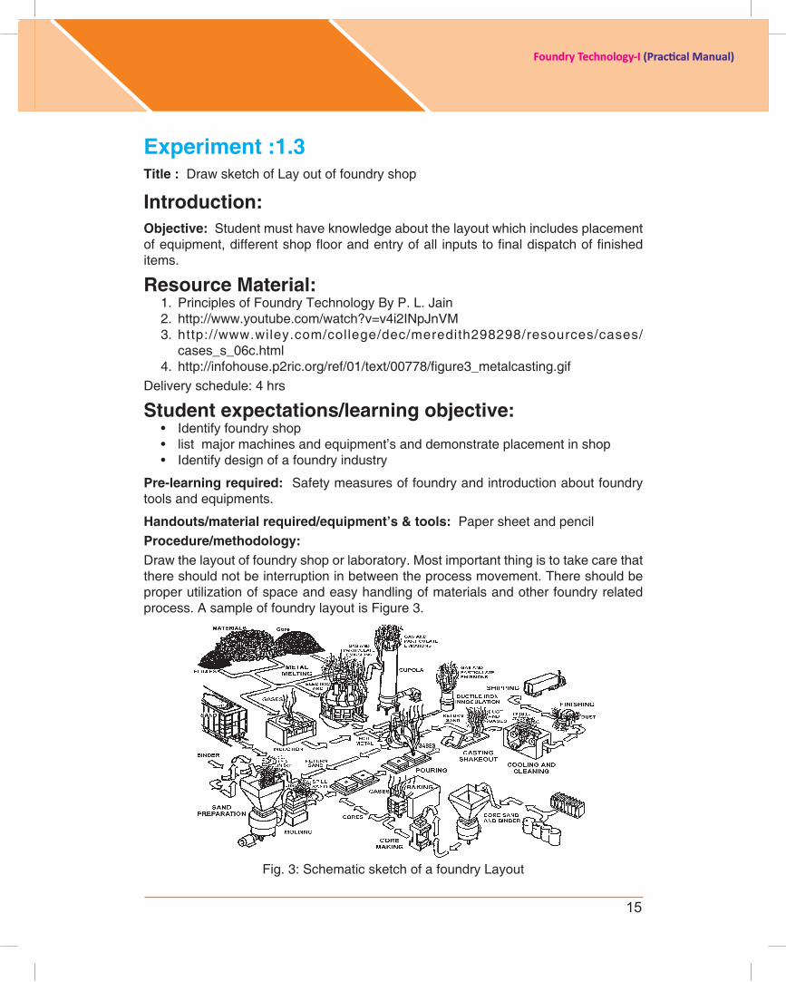
Handouts/material required/equipment’s & tools: Paper sheet and pencilProcedure/methodology:Draw the layout of foundry shop or laboratory. Most important thing is to take care that there should not be interruption in between the process movement. There should be proper utilization of space and easy handling of materials and other foundry related process. A sample of foundry layout is Figure 3.
Fig. 3: Schematic sketch of a foundry Layout
16
Foundry Technology-I (Practical Manual)
Assessment:1. What is importance of Foundry layout?2. PrepareaspecificfoundrylayoutonaA3sheet.
Activity1. Purchase A3 sheet and paste photographs of Cupola, Induction Furnace and
Electric Arc Furnace.2. Use thermocoal to make the model of foundry layout.
individual assessment We recognise that students have different learning styles and needs. The following will help students to assess their progress
Self-Assessment/Learning Plan
Learning objective Outcome Yes/No
FoundryEquipment To understand the uses of equipmentsinfoundry
Foundry Layout Knowledge of design of a foundry plant

17
Foundry Technology-I (Practical Manual)
ExErcisE 2
Experiment : 2 Title : Pattern layout, Location of sprue, runner and riser
introduction:Objective: Design of pattern and the understanding of location of gating and risering system.
resource Material:1. Principle of Foundry Technology, by P. L. Jain2. http://en.wikipedia.org/wiki/Pattern_(casting)3. http://web.iitd.ac.in/~suniljha/MEL120/L5_Metal_Casting2012.pdf4. http://www.themetalcasting.com/casting-pattern-design.html5. http://www.custompartnet.com/wu/SandCasting
Delivery schedule: 15 hrs
student expectations/learning objective: • Demonstratedesigningofapatternfromcomponentdrawing• Listmajorallowancestothepattern• Identifyplacementofsprue,runnerandriser
Pre-learning required: Pattern material, shrinkage allowances for different materials, draft allowances etc.
Handouts/material required/equipment’s & tools: component drawing, A3 drawing sheet, minidrafter, scale, instrument box, pencils and scale etc.
Procedure/methodology:
2.1: Pattern layout Steps involved:
1. Get the working drawing of the part for which the pattern is to be made.
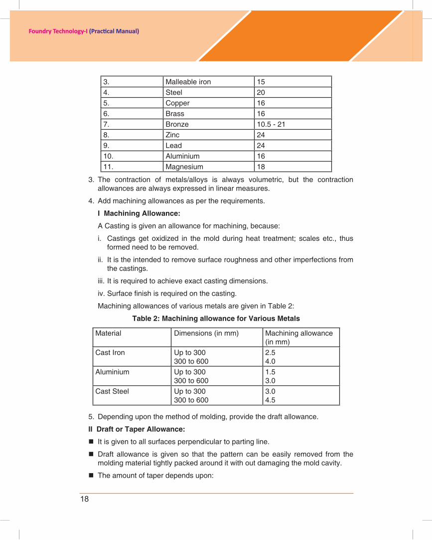
2. Make two views of the part drawing on a sheet, using a shrink rule. A shrink rule ismodifiedformofanordinaryscalewhichhasalreadytakencareofshrinkageallowance for a particular metal to be cast. Shrinkage allowances for different metals are given in Table 1.
Table 1: shrinkage Allowance for different metals
S. No. Metals / Alloys Shrinkage Allowance(mm/meter)
1. Grey cast iron 7 to 10.52. White cast iron 21
18
Foundry Technology-I (Practical Manual)
3. Malleable iron 154. Steel 205. Copper 166. Brass 167. Bronze 10.5 - 218. Zinc 249. Lead 2410. Aluminium 1611. Magnesium 18
3. The contraction of metals/alloys is always volumetric, but the contraction allowances are always expressed in linear measures.
4. Addmachiningallowancesaspertherequirements.
i Machining Allowance:
A Casting is given an allowance for machining, because:
i. Castings get oxidized in the mold during heat treatment; scales etc., thus formed need to be removed.
ii. It is the intended to remove surface roughness and other imperfections from the castings.
iii.Itisrequiredtoachieveexactcastingdimensions.
iv.Surfacefinishisrequiredonthecasting.
Machining allowances of various metals are given in Table 2:
Table 2: Machining allowance for Various Metals
Material Dimensions (in mm) Machining allowance(in mm)
Cast Iron Up to 300300 to 600
2.54.0
Aluminium Up to 300300 to 600
1.53.0
Cast Steel Up to 300300 to 600
3.04.5
5. Depending upon the method of molding, provide the draft allowance.
ii Draft or Taper Allowance:
It is given to all surfaces perpendicular to parting line.
Draft allowance is given so that the pattern can be easily removed from the molding material tightly packed around it with out damaging the mold cavity.
The amount of taper depends upon:

19
Foundry Technology-I (Practical Manual)
i. Shape and size of pattern in the depth direction in contact with the mold cavity.
ii. Molding methods.
iii. Mold materials.
iv. Draft allowance is imparted on internal as well as external surfaces; of course it is more on internal surfaces.
The taper provided by the pattern maker on all vertical surfaces of the pattern so that it can be removed from the sand without tearing away the sides of the sand mold and without excessive rapping by the molder.
Figure 4(a) shows a pattern having no draft allowance being removed from the pattern. In this case, till the pattern is completely lifted out, its sides will remain in contact with the walls of the mold, thus tending to break it.
Fig. 4 (a): Pattern having no draft on vertical edges
Figure 4 (b) is an illustration of a pattern having proper draft allowance. Here, the moment the pattern lifting commences, all of its surfaces are well away from the sand surface. Thus the pattern can be removed without damaging the mold cavity.
Fig. 4(b): Pattern having draft on vertical edges
20
Foundry Technology-I (Practical Manual)
Table 3: suggested draft values for patterns
Pattern material Height of the given surface, (in mm)
Draft angle of surface, degreesExternal Surface Internal surface
Wood Up to 2021 – 5051 – 100101 – 200201 – 300301 – 800801 – 2000Over 2000
3.001.501.000.750.500.500.35-
3.002.501.501.001.000.750.500.25
Metal and plastic Up to 2021 – 5051 – 100101 – 200201 – 300301 – 800
1.501.000.750.500.500.35
3.002.001.000.750.750.50
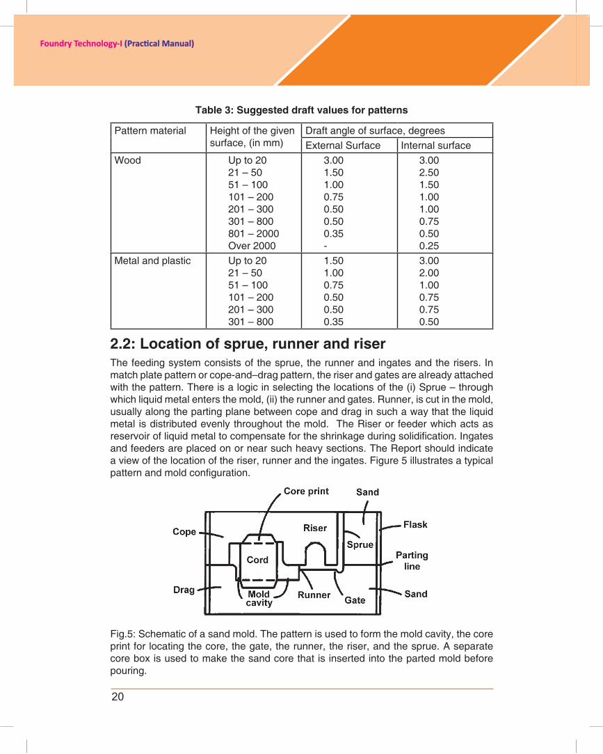
2.2: Location of sprue, runner and riserThe feeding system consists of the sprue, the runner and ingates and the risers. In match plate pattern or cope-and–drag pattern, the riser and gates are already attached with the pattern. There is a logic in selecting the locations of the (i) Sprue – through whichliquidmetalentersthemold,(ii)therunnerandgates.Runner,iscutinthemold,usuallyalongthepartingplanebetweencopeanddraginsuchawaythattheliquidmetal is distributed evenly throughout the mold. The Riser or feeder which acts as reservoirofliquidmetaltocompensatefortheshrinkageduringsolidification.Ingatesand feeders are placed on or near such heavy sections. The Report should indicate a view of the location of the riser, runner and the ingates. Figure 5 illustrates a typical patternandmoldconfiguration.
Fig.5: Schematic of a sand mold. The pattern is used to form the mold cavity, the core print for locating the core, the gate, the runner, the riser, and the sprue. A separate core box is used to make the sand core that is inserted into the parted mold before pouring.

21
Foundry Technology-I (Practical Manual)
Assessment:1. What is shrinkage allowance?2. Write down the list of pattern materials.3. What is necessary of draft in pattern?4. Necessaryrequirementofplacementofriserandrunner.
Activity1. Make a model of pattern using thermo-coal block.2. Make a model of pattern along with runner and riser with thermo-coal block.3. Use different color over thermo-coal model to indicate different types of
allowances.
individual assessment We recognise that students have different learning styles and needs. The following will help students to assess their progress
Self-Assessment/Learning Plan
Learning objective Outcome Yes/No
Pattern materials Materialsrequiredformanufacturing of pattern
Pattern design How to draw pattern from component drawing
Shrinkage allowance
Knowledge of solid shrinkage of metal from freezing point to room temperature
Draft allowance Necessary allowances for ejection of pattern from mold
Placement of runner and riser
It will helpful in design of gating and feeding system
22
Foundry Technology-I (Practical Manual)
ExErcisE 3
Experiment: 3 Title : Sand testing – Shape and size of sand, AFS Sieve analysis of sand, clay content. Preparation of molding sand and standard specimen, Permeability, Hardness determination, tests for Green strength, Dry strength, moisture content. Optimisation of binder and water content by variation of binder and water level.
introduction:Objective:
1. To know morphology to sand grains by optical microscopy.2. Variation of sand grains by sieve analysis.3. Determination of moisture content in sand grains4. Determination of clay content in sand 5. Preparation of sand system6. Preparation of standard sample 7. Determination of harness of standard sand sample8. Determination of permeability of sand mix9. Determination of compressive and shear strength of sand mix10. Optimization of water and binder content.
resource Material:1. Principle of Foundry Technology, by P. L. Jain2. Metal casting by Heine and Rosenthal3. http://en.wikipedia.org/wiki/Foundry_sand_testing4. http://www.sandtesting.com/5. Indian Standards IS1918:1966 Physical testing of foundry sands6. Mold & Core Test Handbook, published by the American Foundry Society, ISBN
0-87433-228-1
Delivery schedule: 30 hrs
student expectations/learning objective: • Identify sand grains/particles morphology• Demonstratemoisturecontentofsandgrains• Demonstratepreparationofsandmix• Listimportanceofvariationofsandsize• Identifyclaycontentofsandparticle• Demonstratetestingofsandsystemformakingmold• Identifypermeability of sand mix
Pre-learning required: preparation of sand mix
Handouts/material required/equipment’s & tools: sand, binder, sand muller, clay washer, oven to dry the sand particles, electronic balance, sand rammer, permeability tester, sieve shaker, optical microscope or magnifying glass, hardness tester, sand universal testing machine etc.
23
Foundry Technology-I (Practical Manual)
Procedure/methodology:
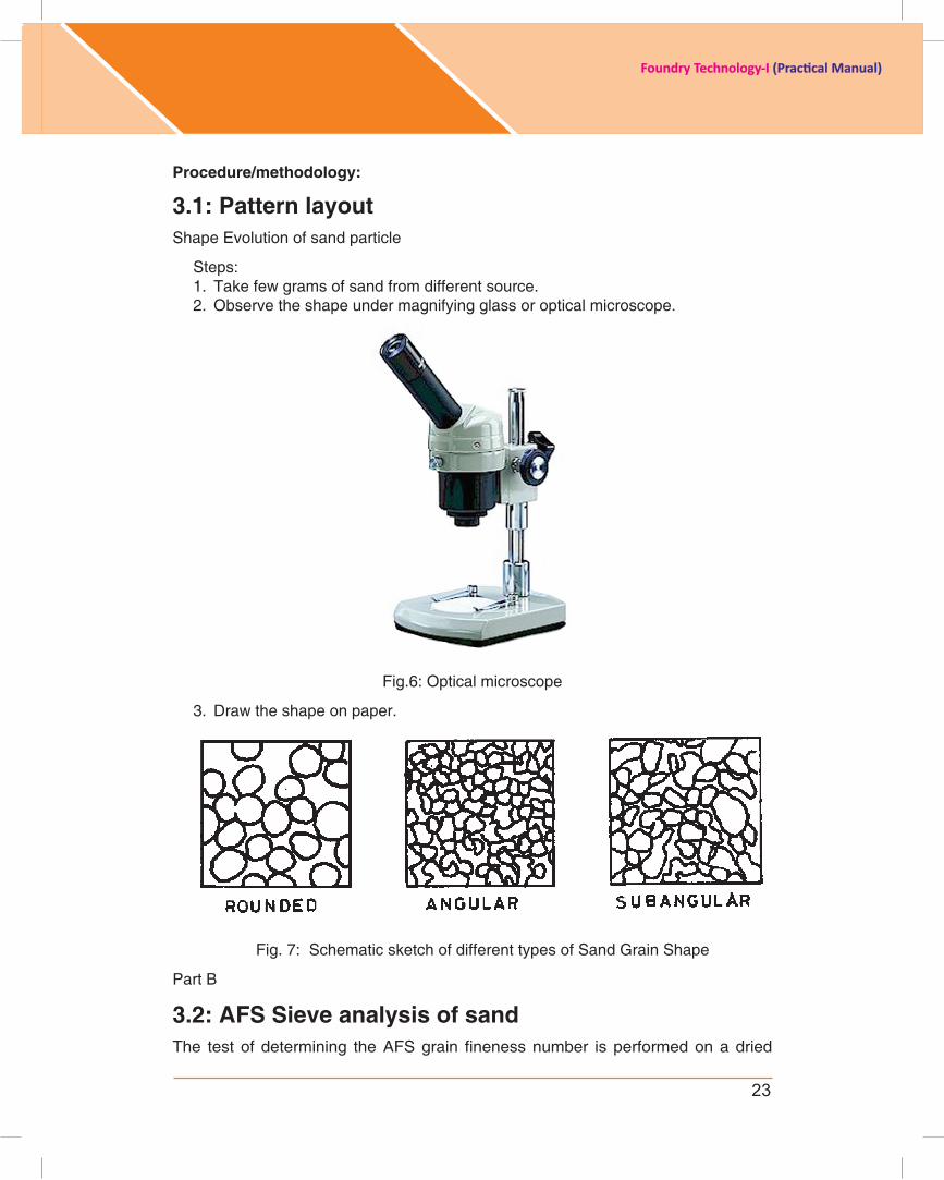
3.1: Pattern layout Shape Evolution of sand particle
Steps: 1. Take few grams of sand from different source.2. Observe the shape under magnifying glass or optical microscope.
Fig.6: Optical microscope
3. Draw the shape on paper.
Fig. 7: Schematic sketch of different types of Sand Grain Shape
Part B
3.2: AFs sieve analysis of sandThe testofdetermining theAFSgrain finenessnumber isperformedonadried
24
Foundry Technology-I (Practical Manual)
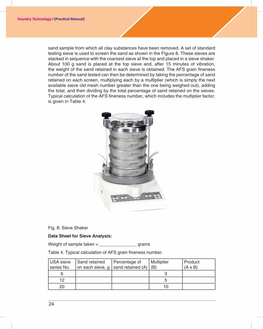
sand sample from which all clay substances have been removed. A set of standard testing sieve is used to screen the sand as shown in the Figure 8. These sieves are stackedinsequencewiththecoarsestsieveatthetopandplacedinasieveshaker.About 100 g sand is placed at the top sieve and, after 15 minutes of vibration, theweightofthesandretainedineachsieveisobtained.TheAFSgrainfinenessnumber of the sand tested can then be determined by taking the percentage of sand retained on each screen, multiplying each by a multiplier (which is simply the next available sieve old mesh number greater than the one being weighed out), adding the total, and then dividing by the total percentage of sand retained on the sieves. TypicalcalculationoftheAFSfinenessnumber,whichincludesthemultiplierfactor,is given in Table 4.
Fig. 8: Sieve Shaker
Data sheet for sieve Analysis:
Weight of sample taken = _______________ grams
Table4.TypicalcalculationofAFSgrainfinenessnumber.
USA sieve series No.
Sand retained on each sieve, g
Percentage of sand retained (A)
Multiplier (B)
Product (A x B)
6 3 12 5 20 10

25
Foundry Technology-I (Practical Manual)
30 20 40 30 50 40 70 50
100 70 140 100 200 140 270 200 Pan 300 Total
AFSgrainfinenessnumber= Total Product Total Percent of Sand Retained
3.3: Tests for Moisture contentThe most accurate method of moisture determination is to dry out the sand and to note weights before and after. The percentage of moisture can be calculated from thedifference intheweights,of theoriginalmoistandtheconsequentlydriedsandsamples.
Percentage of moisture content = (W1-W2)/ (W1) %
Where, W1 = Weight of the sand before drying,
W2 = Weight of the sand after drying.
Fifty grams of tempered sand, accurately weighed and placed in the pan. The timer for theblowerofthemoisturetellerissetfortherequiredtimetodrythesand(approximately5 min) and air at 110°C is blown over and through the sand. The sand is dried after this andweighedagain.Notethedifferenceintheinitialandfinalreadingsanddeterminethe percentage of moisture in the sand.
Data Sheet for Moisture Content
Sample Description Reading Number Moisture Content
% Average %123
3.4: Tests for clay contentThe equipment necessary for determining the percentage of clay inmolding sandconsists of a drying oven, a balance and weights, and a sand washer. Sand clay washer is shown in Figure 9. Clay content test is carried out as follows:

26
Foundry Technology-I (Practical Manual)
A portion of sand sample is thoroughly dried out at 110°C until constant weight is attained. 50 g of this dried sand is placed in a wash bottle. To this sand, 475 c.c. of distilled water and 25 c.c. of 3.0 % caustic soda solution are added. The mixture is stirredfor5mininarapidsandwasher.Sufficientwaterisaddeduptothelevellinemarked on thebottle.Theliquidisthensiphonedoffafter10min.Thebottleisrefilledtwicemoreandsiphonedtheliquidoff.Thesandisplacedintheovenfordrying.Thesand is weighed when it is completely dried and the percentage of clay is determined bythedifferenceintheinitialandfinalweightsofthesample.
Fig.9: Sand clay washer
The clay content can be determined from the difference in weights of the initial and finalsandsamples.
Percentageofclaycontent=(W1-W2)/(W1)X100
Where, W1-Weight of the sand before drying,
W2-Weight of the sand after drying.
Data Sheet for Clay Content
Sample Description Reading Number Clay Content% Average %
123
3.5: specimen Preparation for permeability test, hardness test, strength test of sand mix:Since the permeability of sand is dependent to a great extent, on the degree of
27
Foundry Technology-I (Practical Manual)
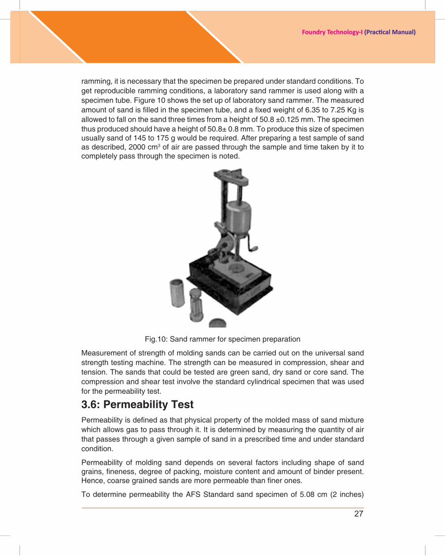
ramming, it is necessary that the specimen be prepared under standard conditions. To get reproducible ramming conditions, a laboratory sand rammer is used along with a specimen tube. Figure 10 shows the set up of laboratory sand rammer. The measured amountofsandisfilledinthespecimentube,andafixedweightof6.35to7.25Kgisallowed to fall on the sand three times from a height of 50.8 ±0.125 mm. The specimen thus produced should have a height of 50.8± 0.8 mm. To produce this size of specimen usuallysandof145to175gwouldberequired.Afterpreparingatestsampleofsandas described, 2000 cm3 of air are passed through the sample and time taken by it to completely pass through the specimen is noted.
Fig.10: Sand rammer for specimen preparation
Measurement of strength of molding sands can be carried out on the universal sand strength testing machine. The strength can be measured in compression, shear and tension. The sands that could be tested are green sand, dry sand or core sand. The compression and shear test involve the standard cylindrical specimen that was used for the permeability test.
3.6: Permeability TestPermeabilityisdefinedasthatphysicalpropertyofthemoldedmassofsandmixturewhichallowsgastopassthroughit.Itisdeterminedbymeasuringthequantityofairthat passes through a given sample of sand in a prescribed time and under standard condition.
Permeability of molding sand depends on several factors including shape of sand grains,fineness,degreeofpacking,moisturecontentandamountofbinderpresent.Hence,coarsegrainedsandsaremorepermeablethanfinerones.
To determine permeability the AFS Standard sand specimen of 5.08 cm (2 inches)

28
Foundry Technology-I (Practical Manual)
diameterand5.08cminheightispreparedbyrammingtherequiredquantityofsandin a smooth surface tube with three blows of standard rammer. This sand specimen is placed in the mercury cup of the permeability meter. The air drum is raised to take 2000 cm3 of air in to the air drum which will be indicated by the graduation on it. The whole air is then allowed to escape through the sand specimen with a pressure of about 10 g/cm3 and the time is recorded. Figure 11 shows the schematic sketch of permeability tester.
Fig. 11: Permeability measuring set up
Then, the permeability number, P is obtained by
Where V = volume of air = 2000 cm3
H = height of the sand specimen = 5.08 cm, P = air pressure, g/cm2
A = cross sectional area of sand specimen= 20.268 cm2
T = time in minutes for the complete air to pass through.
Inserting the above standard values into the expression, we get
Data Sheet for Permeability
SampleDescription
ClayContent
MoistureContent
Time inSecond
PermeabilityReading Average
x
x x
29
Foundry Technology-I (Practical Manual)
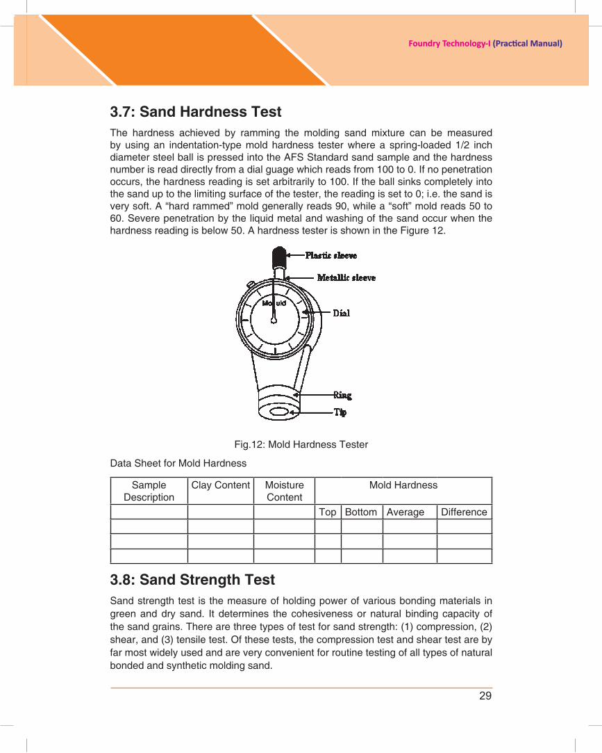
3.7: sand Hardness TestThe hardness achieved by ramming the molding sand mixture can be measured by using an indentation-type mold hardness tester where a spring-loaded 1/2 inch diameter steel ball is pressed into the AFS Standard sand sample and the hardness number is read directly from a dial guage which reads from 100 to 0. If no penetration occurs, the hardness reading is set arbitrarily to 100. If the ball sinks completely into the sand up to the limiting surface of the tester, the reading is set to 0; i.e. the sand is very soft. A “hard rammed” mold generally reads 90, while a “soft” mold reads 50 to 60.Severepenetrationbytheliquidmetalandwashingofthesandoccurwhenthehardness reading is below 50. A hardness tester is shown in the Figure 12.
Fig.12: Mold Hardness Tester
Data Sheet for Mold Hardness
Sample Description
Clay Content Moisture Content
Mold Hardness
Top Bottom Average Difference
3.8: sand strength TestSand strength test is the measure of holding power of various bonding materials in green and dry sand. It determines the cohesiveness or natural binding capacity of the sand grains. There are three types of test for sand strength: (1) compression, (2) shear, and (3) tensile test. Of these tests, the compression test and shear test are by far most widely used and are very convenient for routine testing of all types of natural bonded and synthetic molding sand.
30
Foundry Technology-I (Practical Manual)
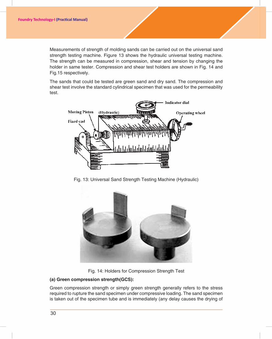
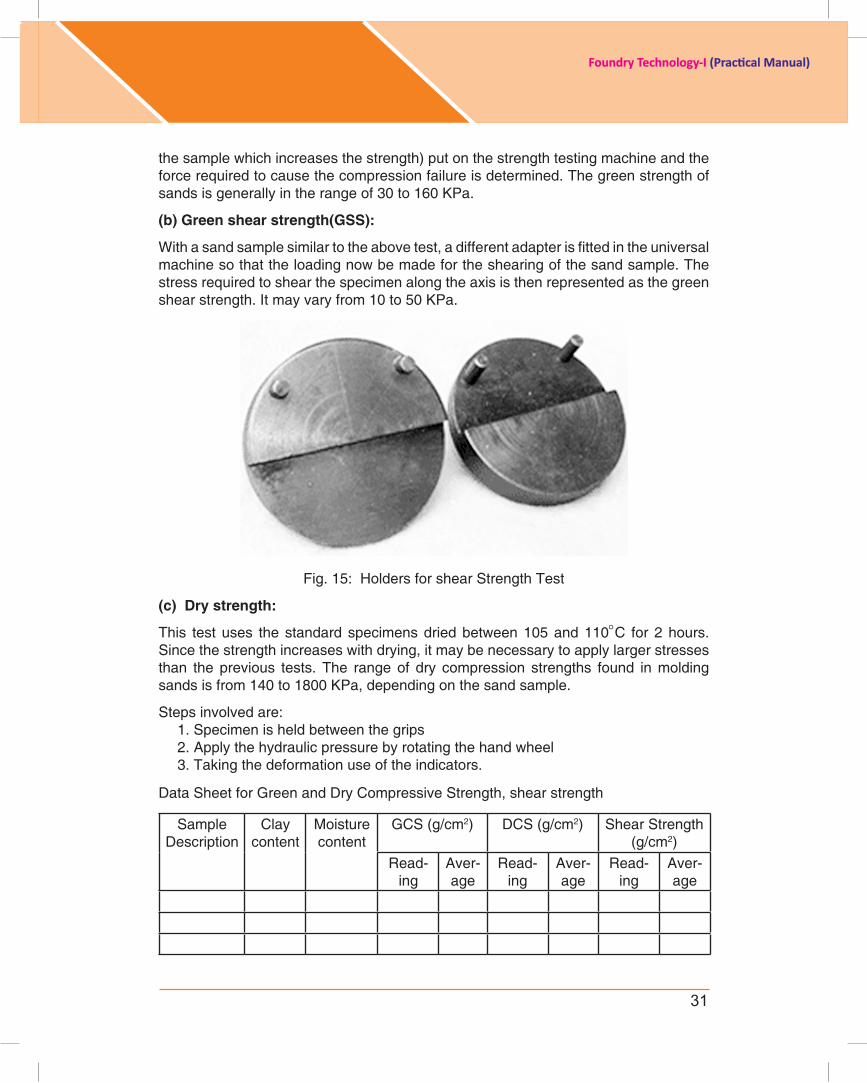
Measurements of strength of molding sands can be carried out on the universal sand strength testing machine. Figure 13 shows the hydraulic universal testing machine. The strength can be measured in compression, shear and tension by changing the holder in same tester. Compression and shear test holders are shown in Fig. 14 and Fig.15 respectively.
The sands that could be tested are green sand and dry sand. The compression and shear test involve the standard cylindrical specimen that was used for the permeability test.
Fig. 13: Universal Sand Strength Testing Machine (Hydraulic)
Fig. 14: Holders for Compression Strength Test
(a) Green compression strength(Gcs):
Green compression strength or simply green strength generally refers to the stress requiredtorupturethesandspecimenundercompressiveloading.Thesandspecimenis taken out of the specimen tube and is immediately (any delay causes the drying of
31
Foundry Technology-I (Practical Manual)
the sample which increases the strength) put on the strength testing machine and the forcerequiredtocausethecompressionfailureisdetermined.Thegreenstrengthofsands is generally in the range of 30 to 160 KPa.
(b) Green shear strength(Gss):
Withasandsamplesimilartotheabovetest,adifferentadapterisfittedintheuniversalmachine so that the loading now be made for the shearing of the sand sample. The stressrequiredtoshearthespecimenalongtheaxisisthenrepresentedasthegreenshear strength. It may vary from 10 to 50 KPa.
Fig. 15: Holders for shear Strength Test
(c) Dry strength:
This test uses the standard specimens dried between 105 and 110°C for 2 hours. Since the strength increases with drying, it may be necessary to apply larger stresses than the previous tests. The range of dry compression strengths found in molding sands is from 140 to 1800 KPa, depending on the sand sample.
Steps involved are:1. Specimen is held between the grips2. Apply the hydraulic pressure by rotating the hand wheel3. Taking the deformation use of the indicators.
Data Sheet for Green and Dry Compressive Strength, shear strength
Sample Description
Clay content
Moisturecontent
GCS (g/cm2) DCS (g/cm2) Shear Strength (g/cm2)
Read-ing
Aver-age
Read-ing
Aver-age
Read-ing
Aver-age

32
Foundry Technology-I (Practical Manual)
3.9: Optimizations of binder and water content by variation of binder and water level. (a) Optimizations of binder content by variation of binder level
Optimization of binder content is carried out by varying the level of binder and keeping themoisturefixedinthesandmix.
steps:1. Make the sand samples using different % of binder like 2%, 4%, 5%, 6% and 8%
etc.bykeepingthemoisturecontentfixed.2. Take the data of permeability number, hardness number and green compressive
strength (GCS)3. Plot the permeability number, hardness number and GCS with binder content.4. Optimize binder content to achieve better permeability, hardness and compressive
strength of sand
COMPLETEDATASHEETFOREXPT.3.9(a)
SampleNo.
Moisture Content (%)
BinderContent (%)
PermeabilityReading
HardnessNumber
GCS(g/cm2)
1 22 43 54 65 8
(b) Optimization of water content by variation of water level
Optimization of binder content is carried out by varying the level of binder and keeping themoisturefixedinthesandmix.
steps:1. Make the sand samples using different % of water like 3%, 5%, 6%, 7% and 8%
etc.bykeepingthebindercontentfixed.2. Take the data of permeability number, hardness number and green compressive
strength (GCS)3. Plot the permeability number, hardness number and GCS with water content.4. Optimize water content to achieve better permeability, hardness and compressive
strength of sand
COMPLETEDATASHEETFOREXPT.3.9(b)
SampleNo.
Moisture Content (%)
BinderContent (%)
PermeabilityReading
HardnessNumber
GCS(g/cm2)
1 32 5
33
Foundry Technology-I (Practical Manual)
3 64 75 8
Assessment:1. What is sand mix?2. Draw the sand shape on paper.3. What is size distribution of sand grains.4. What do you understand by permeability?5. How can you make a standard sand specimen for permeability and strength
testing?6. Write down the formula for determination of moisture content.7. Write down the formula of permeability number?8. What is mold coating?
Activity1. Student can make ASTM standard specimen using thermo-coal.2. Student can collect different source of sand like river bank sand, beach sand
and other source to see morphology of sand.
individual assessment
We recognise that students have different learning styles and needs. The following will help students to assess their progress
Self-Assessment/Learning Plan
Learning objective Outcome Yes/No
Sand morphology Understand the packing of sand in the mold
Sand size distribution Variation of sand size and applicability for foundry practice
Sand sample preparation For different testing of sand systems
Moisture content determination
To determine how much moisturefurtherrequirefor sand system
Permeability number determination
Ability of sand mix to pass the air/gas through sand mix after ramming
34
Foundry Technology-I (Practical Manual)
ExErcisE 4
Experiment: 4 Title : Preparation of a green sand mold with a simple pattern, use of mold coating, Measurement of mold hardness
introduction:Objective:
1. Preparation of green sand mold2. Application of mold coating3. Determination of mold hardness
resource Material:1. Principle of Foundry Technology, by P. L. Jain2. Metal casting by Heine and Rosenthal3. http://afsosu.org.ohio- state.edu/resources/Foundry%20Doc3C%20Green%20
Sand%20Molding%20Procedure.pdf4. http://www.simpsongroup.com/tech/rpt-sales-Fundamentals%20of%20
Sand%20Control.pdf5. http://www.foundry101.com/new_page_7.htm6. http://www.youtube.com/watch?v=TSLZQU64F-I7. http://www.foseco.com.tr/tr/downloads/FoundryPractice/237-01_Coatings_for_
the_green_sand_molding.pdf8. http://www.jsmccormick.com/coremold.php9. http://www.thaifoundryequipment.com/index.php?lay=show&ac=article&Id=233
169
Delivery schedule: 5 hrs
student expectations/learning objective: • Demonstratepreparationofgreensandmold• Applicationofmoldwashovermoldsurface• Calculatemeasurementofmold
Pre-learning required: preparation of green sand mix
Handouts/material required/equipment’s & tools: sand, binder, sand muller, foundry tools, hardness tester, brush to apply coating over mold surface, coating material etc.
Procedure/methodology:
Experiment steps:
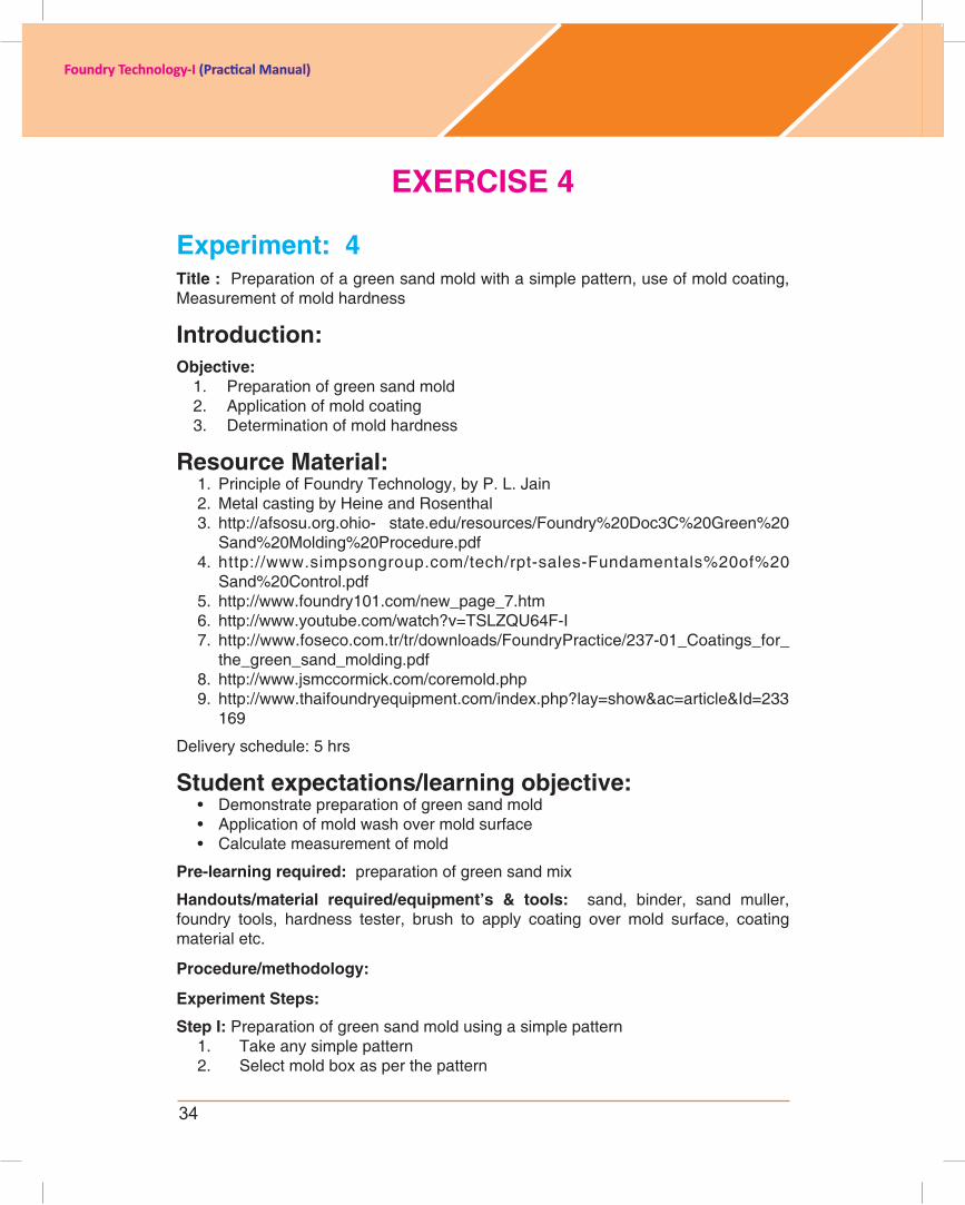
step i: Preparation of green sand mold using a simple pattern1. Take any simple pattern2. Select mold box as per the pattern
35
Foundry Technology-I (Practical Manual)
3. Makethesandmixusingadefiniteamountofmoistureandbinder.4. Identify which side of pattern should be on the cope or drag side. Flasks are
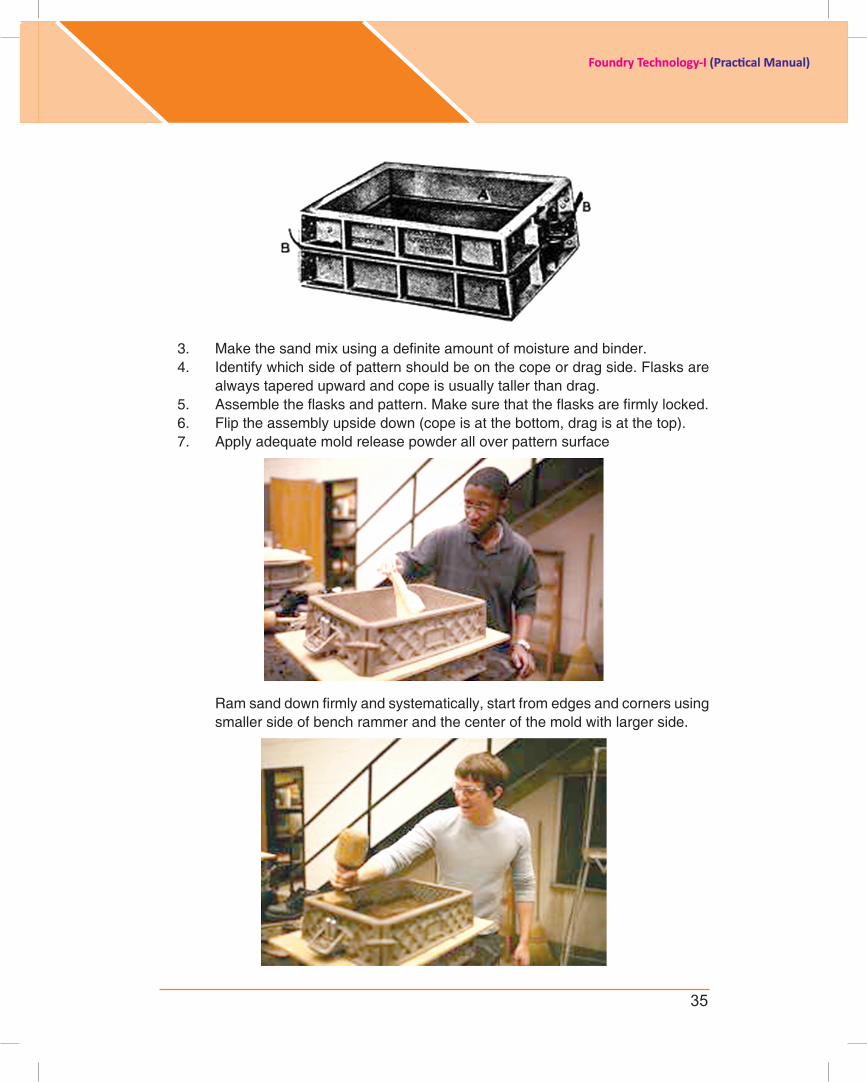
always tapered upward and cope is usually taller than drag.5. Assembletheflasksandpattern.Makesurethattheflasksarefirmlylocked.6. Flip the assembly upside down (cope is at the bottom, drag is at the top).7. Applyadequatemoldreleasepowderalloverpatternsurface
Ramsanddownfirmlyandsystematically,startfromedgesandcornersusingsmaller side of bench rammer and the center of the mold with larger side.
36
Foundry Technology-I (Practical Manual)
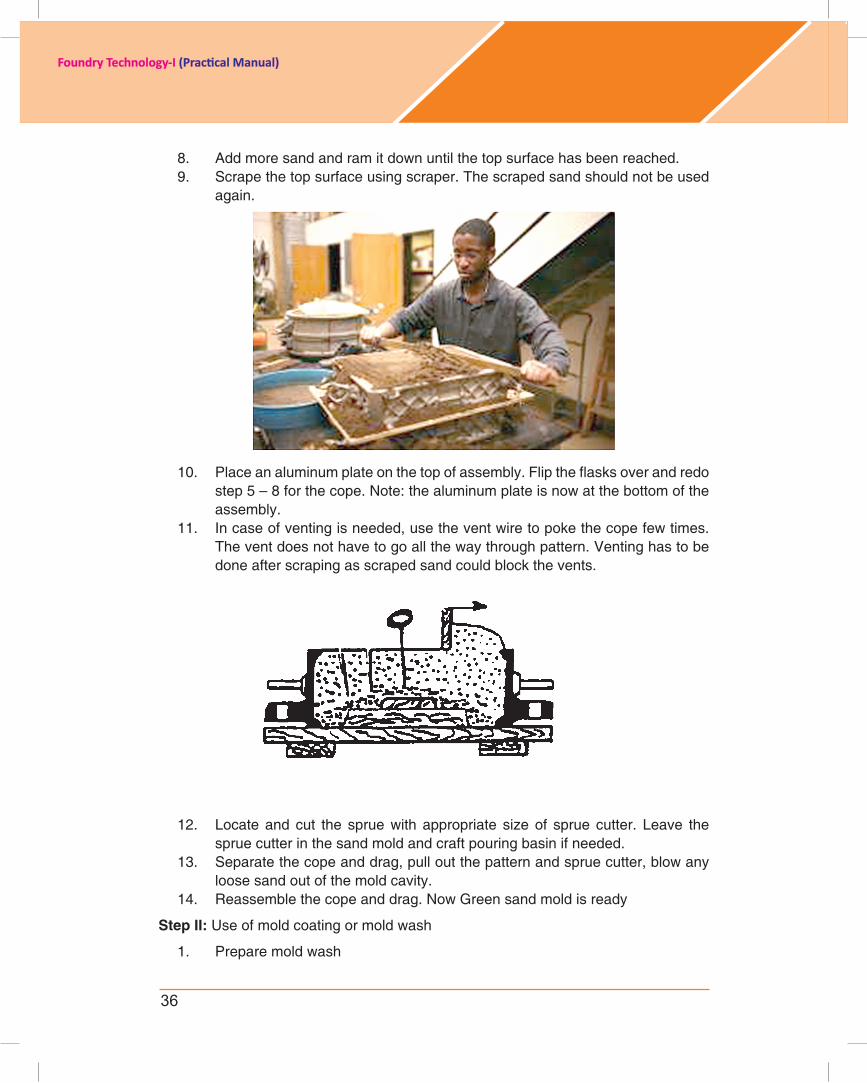
8. Add more sand and ram it down until the top surface has been reached.9. Scrape the top surface using scraper. The scraped sand should not be used
again.
10. Placeanaluminumplateonthetopofassembly.Fliptheflasksoverandredostep 5 – 8 for the cope. Note: the aluminum plate is now at the bottom of the assembly.
11. In case of venting is needed, use the vent wire to poke the cope few times. The vent does not have to go all the way through pattern. Venting has to be done after scraping as scraped sand could block the vents.
12. Locate and cut the sprue with appropriate size of sprue cutter. Leave the sprue cutter in the sand mold and craft pouring basin if needed.
13. Separate the cope and drag, pull out the pattern and sprue cutter, blow any loose sand out of the mold cavity.
14. Reassemble the cope and drag. Now Green sand mold is ready
step ii: Use of mold coating or mold wash
1. Prepare mold wash
37
Foundry Technology-I (Practical Manual)
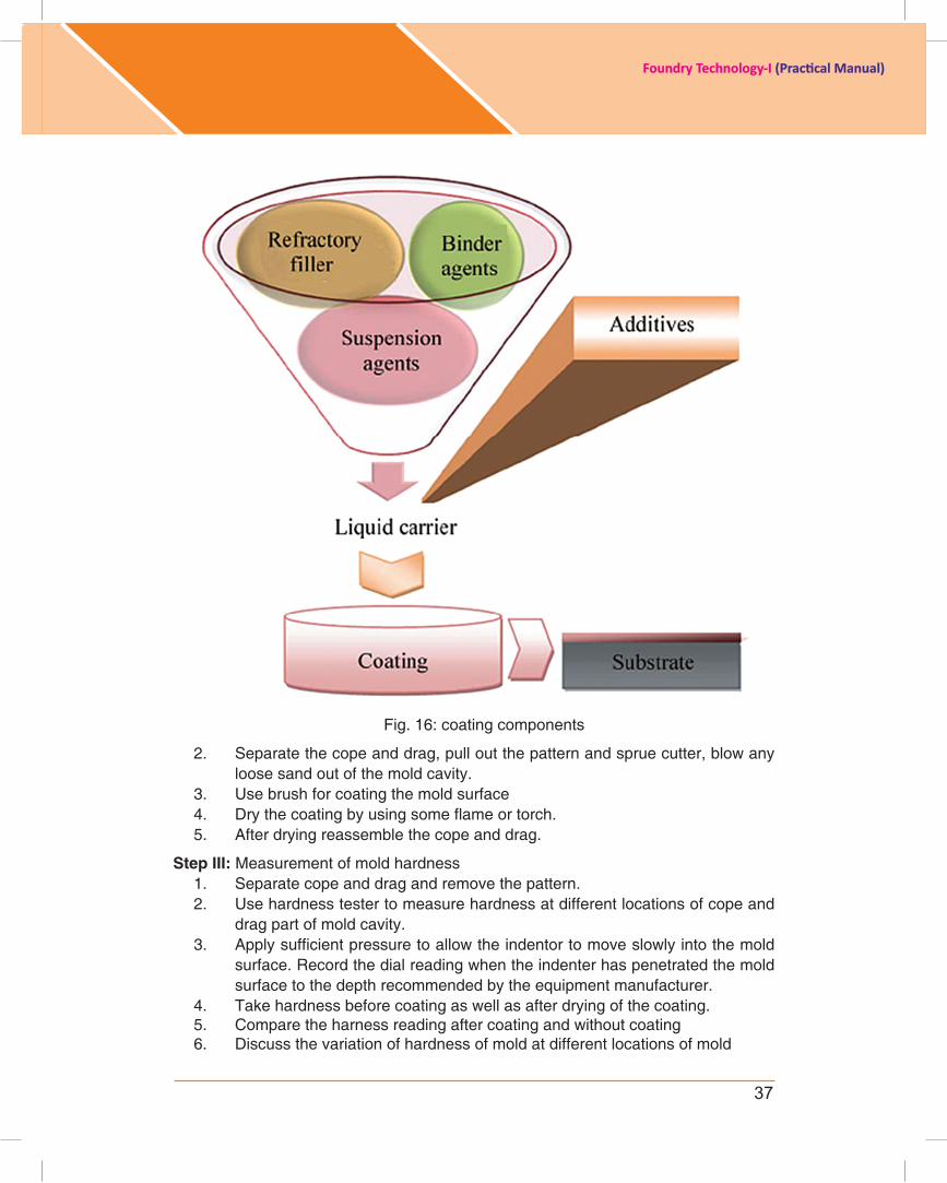
Fig. 16: coating components
2. Separate the cope and drag, pull out the pattern and sprue cutter, blow any loose sand out of the mold cavity.
3. Use brush for coating the mold surface4. Drythecoatingbyusingsomeflameortorch.5. After drying reassemble the cope and drag.
step iii: Measurement of mold hardness1. Separate cope and drag and remove the pattern.2. Use hardness tester to measure hardness at different locations of cope and
drag part of mold cavity.3. Applysufficientpressuretoallowtheindentortomoveslowlyintothemold
surface. Record the dial reading when the indenter has penetrated the mold surfacetothedepthrecommendedbytheequipmentmanufacturer.
4. Take hardness before coating as well as after drying of the coating.5. Compare the harness reading after coating and without coating6. Discuss the variation of hardness of mold at different locations of mold

38
Foundry Technology-I (Practical Manual)
7. Also discuss the effect of coating on mold harness.8. Compare the results in tabular form.
COMPLETEDATASHEETFOREXPT.4
SampleNo.
Moisture Content(%)
BinderContent(%)
Hardness number (with-out coating)
HardnessNumber(after Coating)
1 32 53 64 75 8
Assessment:
1. What is green sand?
2. Write down the name of different mold wash material.
3. Write down the name of method of application of mold wash over mold surface.
4. What is necessity of determination of mold hardness?
Activity
1. Make a green sand mold of your foot hand only. Do not use any foundry tools.
2. Make a different numbers of molds by varying different percentage of binder and measure average hardness of molds and discuss the results with variation of binder.
individual assessment
We recognize that students have different learning styles and needs. The following will help students to assess their progress
Self-Assessment/Learning Plan
Learning objective Outcome Yes/No
Green sand molding Method and steps of green mold preparation.
Proportion of green sand ingredients
Composition of sand system
Mold wash Mold wash materials, it uses to the mold
Mold hardness Erosion resistance, rammingness of sand mix