classification of communication networks - mycsvtu...
TRANSCRIPT
MYcsvtu Notes
1
Data Communication Network The major criteria that a Data Communication Network must meet are
i 11a Performance
ii 11b Consistency
iii 11c Reliability
iv 11d Recovery and
v 11e Security
a Performance
Performance is the defined as the rate of transferring error free data It is measured by the
Response Time Response Time is the elasped time between the end of an inquiry and the
beginning of a response Request a file transfer and start the file transfer Factors that
affect Response Time are
a Number of Users More users on a network - slower the network will run
b Transmission Speed speed that data will be transmitted measured in bits per
second (bps)
c Media Type Type of physical connection used to connect nodes together
d Hardware Type Slow computers such as XT or fast such as Pentiums
e Software Program How well is the network operating system (NOS) written
b Consistency
Consistency is the predictability of response time and accuracy of data
a Users prefer to have consistent response times they develop a feel for normal
operating conditions For example if the normal response time is 3 sec for
printing to a Network Printer and a response time of over 30 sec happens we
know that there is a problem in the system
b Accuracy of Data determines if the network is reliable If a system loses data
then the users will not have confidence in the information and will often not use
the system
c Reliability
MYcsvtu Notes
2
Reliability is the measure of how often a network is useable MTBF (Mean Time
Between Failures) is a measure of the average time a component is expected to operate
between failures Normally provided by the manufacturer A network failure can be
hardware data carrying medium and Network Operating System
d Recovery
Recovery is the Networks ability to return to a prescribed level of operation after a
network failure This level is where the amount of lost data is nonexistent or at a
minimum Recovery is based on having Back-up Files
e Security
Security is the protection of Hardware Software and Data from unauthorized access
Restricted physical access to computers password protection limiting user privileges and
data encryption are common security methods Anti-Virus monitoring programs to
defend against computer viruses are a security measure
f Applications
The following lists general applications of a data communication network
i Electronic Mail (e-mail or Email) replaces snail mail E-mail is the forwarding of
electronic files to an electronic post office for the recipient to pick up
ii Scheduling Programs allow people across the network to schedule appointments
directly by calling up their fellow workers schedule and selecting a time
iii Videotext is the capability of having a 2 way transmission of picture and sound
Games like Doom Hearts distance education lectures etc
iv Groupware is the latest network application it allows user groups to share
documents schedules databases etc ex Lotus Notes
v Teleconferencing allows people in different regions to attend meetings using
telephone lines
vi Telecommuting allows employees to perform office work at home by Remote
Access to the network
vii Automated Banking Machines allow banking transactions to be performed
everywhere at grocery stores Drive-in machines etc
viii Information Service Providers provide connections to the Internet and other
information services Examples are Compuserve Genie Prodigy America On-
Line (AOL) etc
ix Electronic Bulletin Boards (BBS - Bulletin Board Services) are dialup
connections (use a modem and phone lines) that offer a range of services for a fee
x Value Added Networks are common carriers such as AGT Bell Canada etc (can
be private or public companies) who provide additional leased line connections to
MYcsvtu Notes
3
their customers These can be Frame Relay ATM (Asynchronous Transfer
Mode) X25 etc The leased line is the Value Added Network
Classification of communication networks
Communication networks are usually defined by their size and complexity We can
distinguish four main types
Small These networks are for the connection of computer subassemblies They
are usually contained within a single piece of equipment
Local area networks (LAN) These networks connect computer equipment and
other terminals distributed in a localised area eg a university campus factory
office The connection is usually a cable or fibre and the extent of the cable
defines the LAN
Metropolitan area networks (MAN) These networks are used to interconnect
LANs that are spread around say a town or city This kind of network is a high
speed network using optical fibre connections
Wide area networks (WAN) These networks connect computers and other
terminals over large distances They often require multiple communication
connections including microwave radio links and satellite
LANs may have a number of different physical configurations ie the manner in which
workstations on the LAN are physically connected The physical configuration will often
reflect the media access control (MAC) method used to allow the workstation to gain
access to the connection media Most LANs are shared medium networks ie there is
effectively one link between all the workstations on the LAN and each must wait its turn
for the use of the media There are various methods of controlling how and when a
workstation gets its turn to use the media eg carrier sense multiple access with
collision detect (CSMACD) or the use of token passing
One of the most popular configurations is the bus arrangement for example Ethernet and
token-bus (Figure )
MYcsvtu Notes
4
Figure LAN bus arrangement
In this configuration all the workstations effectively hang off from one piece of wire
Another common configuration is a ring for example token-ring (Figure )
Figure LAN ring arrangement
A star configuration is not seldom used to interconnect workstations on a LAN Instead it
is used to interconnect LANs via an exchange or switch however emerging
asynchronous transfer mode (ATM) technology (and other high-speed networks) may
make the use of star configurations a more common occurrence (Figure )
MYcsvtu Notes
5
Figure LAN star arrangement
You may hear these configurations referred to as LAN topologies LAN segments may
be interconnected by use of a backbone LAN that allows communication between the
segments The segments help to localise traffic eg within an office or a single floor in a
building Each segment is a LAN in itself but is connected to the backbone via a bridge
(Figure )
Figure Backbone interconnecting LAN segments
MYcsvtu Notes
6
WANs often exploit public networks such as the public telephone system (Figure )
There are two types of public network
Public switched telephone network (PSTN) This is the ordinary telephone
system This system exists in all countries of the world It was designed
specifically for the transmission of voice communication Digital systems
employing this network must produce a voice-like signal and accept the low
transmission rates
Public switched data network (PSDN) This is a public network designed
specifically for the transmission of digital data They arose from privately owned
WANs that required higher performance than the PSTN Many countries of the
world are introducing PSDN services They can support much higher transmission
rates An integrated services digital network (ISDN) is the term given to all-
digital networks that can carry simultaneously voice and data communication and
offer additionally a variety of teletex services ISDN services are being introduced
all round the world and are indeed on offer in the UK
Figure WANs to interconnect LANs
MANs are now taking some of the roles that WANs once had in particular environments
for LAN LAN interconnection due to the high speeds that they offer compared to most
MYcsvtu Notes
7
PSTNs and PSDNs eg FDDI and DQDB offer 100Mbs whereas a PSTN line may
offer say 192Kbs with a fast modem
At the present time the worlds communication systems are in a state of flux Historically
digital computing equipment conformed to the requirements of the PSTN Now
increasingly analogue traffic such as voice and video is conforming to the requirements
of the PSDN
Public networks employ two types of switching Switching describes the method by
which the corresponders are connected A circuit switched network (CSN) establishes a
connection through the network that is then used exclusively by the two correspondents
(Of course only in 19th century telephone exchanges is the switching actually current
driven) The PSTN is a circuit switched network A packet switched network (PSN)
divides the message into packets that are addressed to the recipient The packets are then
forwarded through the network together with many other packets These are locally
distributed on arrival The Post Office is a packet switched network More relevantly
LAN communication is exclusively via a PSN The outstanding advantage of the PSN is
that the two correspondents can communicate at different rates permitting much more
efficient use of the communication channel
The Communications Channel
A communication channel can be simplex in which only one party can transmit full-
duplex in which both correspondents can transmit and receive simultaneously or half-
duplex in which the correspondents alternate between transmitting and receiving states
(such as conversing adults) Even though the channel might be capable of supporting full-
duplex communication if the corresponding entities are not capable of transmitting and
receiving simultaneously the communications system will be half-duplex (as in the
example of the conversing adults)
Communication between two entities can be considered either in-band or out-of-band
depending on context In-band communication is communication which occurs via the
primary channel between the communicating entities Out-of-band communication occurs
via an alternative channel which is not considered to be the primary channel between the
entities
Which channel is primary and which is an alternate depends on context and the existence
of an alternative channel In the case of a conversation between two people the primary
channel could consist of verbal communication while the alternate channel consists of
visual body language Of course if emotions rise these two channels might reverse roles
with body language becoming the primary channel
MYcsvtu Notes
8
Simplex communication
From Wikipedia the free encyclopedia
Jump to navigation search
Simplex communication is a name for a type of communication circuit There are two
(contradictory) definitions that have been used for the term In both cases the other
definition is referred to as half duplex
Contents
[hide]
1 One way at a time
2 One way only
o 21 Examples according to ANSI definition
3 References
4 See also
One way at a time
According to the ITU-T definition a simplex circuit is one where all signals can flow in
only one direction at a time This was also the way Western Union used the term when
describing the duplex and simplex capacity of their new transatlantic telegraph cable
completed between Newfoundland and the Azores in 1928[1]
The same definition for a
simplex radio channel was used by the National Fire Protection Association in 2002[2]
One way only
According to the ANSI definition a simplex circuit is one where all signals can flow in
only one direction These systems are often employed in broadcast networks where the
receivers do not need to send any data back to the transmitterbroadcaster
To put it simply you wont find your radio receiver actually sending out any information
all it does is receive so information moves one way only from the radio broadcasting
station to your radio receiver
Half-Duplex
MYcsvtu Notes
9
A simple illustration of a half-duplex communication system
A half-duplex system provides for communication in both directions but only one
direction at a time (not simultaneously) Typically once a party begins receiving a signal
it must wait for the transmitter to stop transmitting before replying
An example of a half-duplex system is a two-party system such as a walkie-talkie style
two-way radio wherein one must use Over or another previously designated command
to indicate the end of transmission and ensure that only one party transmits at a time
because both parties transmit on the same frequency A good analogy for a half-duplex
system would be a one lane road with traffic controllers at each end Traffic can flow in
both directions but only one direction at a time with this being regulated by the traffic
controllers
Note that this is one of two contradictory definitions for half-duplex This
definition matches the ANSI standard For more detail see Simplex
communication
Full-Duplex
A simple illustration of a full-duplex communication system
A full-duplex system allows communication in both directions and unlike half-duplex
allows this to happen simultaneously Land-line telephone networks are full-duplex since
they allow both callers to speak and be heard at the same time A good analogy for a full-
duplex system would be a two lane road with one lane for each direction
Examples Telephone Mobile Phone etc
MYcsvtu Notes
10
Two way radios can be for instance designed as full-duplex systems which transmit on
one frequency and receive on a different frequency This is also called frequency-division
duplex Frequency-division-duplex systems can be extended to farther distances using
pairs of simple repeater stations owing to the fact the communications transmitted on any
one frequency always travels in the same direction
Full-duplex Ethernet connections work by making simultaneous use of all four physical
pair of twisted cable (which are inside the insulation) where two pair are used for
receiving packets and two pair are using for sending packets to a directly connected
device This effectively makes the cable itself a collision-free environment and
theoretically doubles the maximum bandwidth that can be supported by the connection
Channel Characteristics
A communications channel may be described in terms of its characteristic properties
These channel characteristics includebandwidth (how much information can be
conveyed across the channel in a unit of time commonly expressed in bits per second or
bps7 ) quality (how reliably can the information be correctly conveyed across the
channel commonly in terms of bit error rate or BER8 ) and whether the channel is
dedicated (to a single source) or shared (by multiple sources)
Obviously a higher bandwidth is usually a good thing in a channel because it allows more
information to be conveyed per unit of time High bandwidths mean that more users can
share the channel depending on their means of accessing it High bandwidths also allow
more demanding applications (such as graphics) to be supported for each user of the
channel
The capability of a channel to be shared depends of course on the medium used A shared
channel could be likened to a school classroom where multiple students might attempt to
simultaneously catch the teachers attention by raising their hand the teacher must then
arbitrate between these conflicting requests allowing only one student to speak at a time
Reliability of communication is obviously important A low quality channel is prone to
distorting the messages it conveys a high quality channel preserves the integrity of the
messages it conveys Depending on the quality of the channel in use between
communicating entities the probability of the destination correctly receiving the message
from the source might be either very high or very low If the message is received
incorrectly it needs to be retransmitted
If the probability of receiving a message correctly across a channel is too low the system
(source channel message destination) must include mechanisms which overcome the
errors introduced by the low quality channel Otherwise no useful communication is
possible over that channel These mechanisms are embodied in the communication
protocols employed by the corresponding entities
MYcsvtu Notes
11
The effective bandwidth describes what an application experiences and depends on the
quality of service (QOS) provided by the channel For example modems scale back their
transmission speed based largely on their perception of channel quality in order to
optimally use the transmission medium
In general shared and reliable channels are more resource efficient than those which
enjoy neither of these characteristics Shared channels enjoy greater efficiency than
dedicated ones because most data communication is bursty in nature with long idle
periods punctuated by brief message transmissions Reliable channels are more efficient
than unreliable ones because retransmissions are not required as often (because there are
fewer transmission-induced errors)
The OSI Reference Model
The Open Systems Interconnect (OSI) reference model is commonly used to describe in
an abstract manner the functions involved in data communication This model originally
conceived in the International Organization for Standardization (ISO) defines data
communications functions in terms of layers
In the OSI reference model each layer is responsible for certain basic functions such as
getting data from one device to another or from one application on a computer to another
The functions at each layer both depend and build on the functions-called services-
provided by the layers below it Communication between peer entities at a given layer is
done via one or more protocols this communication is invoked via the interface with the
layer below
The OSI reference model is depicted in Table 01 Successful communication between
two applications depends on successful functions at all seven layers In terms of
implementation it is possible for some layers to be trivial in the end what is required
depends on the needs of the applications (and people) engaged in communication
Table 01 OSI Reference Model
Layer Title
7 Application
Higher Layers 6 Presentation
5 Session
4 Transport
MYcsvtu Notes
12
3 Network
Lower Layers 2 Data Link
1 Physical
We must emphasize that the definition of a layered data communication architecture is
only an abstraction The intent of this definition is to unambiguously describe the
functions involved in data communication in a way which allows different systems to be
compared The OSI reference model definition is intended to neither imply nor constrain
the implementation of any communication system
Although various companies and standards bodies have created different layered
communications models the OSI reference model remains the universally-accepted
common denominator for abstract definition Other models define the layer functions
somewhat differently and often have fewer than seven layers In some cases constituent
protocols were specified before the abstract models defining the end-to-end
communication
We will now review the functions of the OSI layers and some of the primary protocols at
each layer9
Layer 1 - The Physical Layer
The physical layer functions include all physical aspects of communicating between two
directly-connected physical entities Typically these physical properties include
electromechanical characteristics of the medium or link between the communicating
physical entities such as connectors voltages transmission frequencies etc This layer
summarizes the physics which underlie the communication path
The essential service provided by the physical layer consists of an unstructured bit
stream which can be used by higher layers to provide the basis for higher layer
communication services An example of a physical layer is the ink on paper used by this
book to convey information Another example is the radio frequencies used in a wireless
communications system
Layer 2 - The Data Link Layer
The data link layer accepts the unstructured bit stream provided by the physical layer and
provides reliable transfer of data between two directly-connected Layer 2 entities
Directly-connected means that the Layer 2 entities communication path does not
require another Layer 2 entity However this does not imply a dedicated path in the case
MYcsvtu Notes
13
of Ethernet many Layer 2 entities can be sharing a common (physical) medium such as a
coaxial cable or a 10BASE-T hub
Layer 2 functionality is limited in scope-delivery of messages over a local area It could
be likened to an intra-office correspondence between co-workers there is a need for
reliability but addressing is relatively simple Local area networks (LANs) operate at
Layer 2
The data link layer is itself conceptually subdivided into two sublayers-medium access
control and logical link control-which more specifically define the primary aspects of
data link layer functionality However this conceptual partitioning by the IEEE 802
committee is somewhat arbitrary and subject to debate
The MAC Sublayer
The medium access control (MAC) sublayer is closely associated with the physical layer
and defines the means by which the physical channel (medium) may be accessed It
coordinates the attempts to seize a shared channel by multiple MAC entities much as a
school teacher must arbitrate between pupils conflicting desires to speak The MAC layer
commonly provides a limited form of error control especially for any header information
which defines the MAC-level destination and higher-layer access mechanism
Ethernet (IEEE 8023) is a prime example of a shared medium with a defined MAC
sublayer functionality The shared medium in Ethernet has traditionally consisted of a
coaxial cable into which multiple entities were tapped as depicted in Figure 05
Although this topology still applies conceptually a hub and spoke medium is now
typically used in which the earlier coaxial cable has been physically collapsed into a hub
device
Figure 05 Ethernet MAC System
11
As a contention medium Ethernet defines how devices sense a channel for its
availability wait when it is busy seize the channel when it becomes available and back-
off for a random length of time following a collision with another simultaneously
MYcsvtu Notes
14
transmitting device On a shared channel such as Ethernet only a single entity can
transmit at a time or messages will be garbled
Not all shared channels involve contention A prime example of a contentionless shared
medium is token ring (IEEE 8025) in which control of the channel is rotated between
the devices sharing the channel in a deterministic round-robin manner Conceptually
control of the channel is given to the entity currently possessing a token If the device
has nothing to transmit it passes the token to the next device attached to the topological
ring depicted in Figure 06
Figure 06 Token Ring MAC System
11
IEEE-defined MAC sublayer addresses are six bytes long and permanently assigned to
each device typically called a network interface card orNIC The IEEE administers the
assignment of these addresses in blocks to manufacturers to assure the global uniqueness
that the MAC sublayer protocols rely on for plug Ocircn play network setup Each
manufacturer must assure individual device identifier uniqueness within their assigned
block
The LLC Sublayer
The logical link control (LLC) sublayer is responsible for reliable transfer of messages-
called frames or more formally link protocol data units (LPDUs)-between two directly-
connected Layer 2 entities Functions needed to support this reliable transfer include
framing (indicating where a Layer 2 message begins and ends) sequence control error
control and flow control
MYcsvtu Notes
15
The degree to which sequence error and flow control are provided by the LLC sublayer
is determined by whether the link protocol is connection-oriented or connectionless A
connectionless link protocol provides little if any support for these functions A
connection-oriented link might use a windowing technique for these functions in which
frames are individually numbered and acknowledged by their sequence number with
only a few such frames outstanding at any time
The connection-oriented functions of sequencing error and flow control provide a
foundation for services provided by higher layers As mentioned earlier not all layer or
sublayer functions are explicitly designed or implemented in any given system Provision
of these functions depends on the services required by higher layers
If the connection-oriented functions of the LLC sublayer are not implemented they must
be performed by higher layers for reliable end-to-end communication If these functions
are provided by several layers they might be somewhat redundant and add unnecessary
overhead (inefficiency) to the system In the worst case redundant provision of these
functions at multiple layers could serve cross purposes and actually degrade overall
system performance
An example of a connectionless LLC protocol is frame relay (T1617 618) which
defines point-to-point links with switches connecting individual links in a mesh topology
In a frame relay network endpoints are connected by a series of links and switches
Because frame relay is defined in terms of the links between frame relay access devices
(FRADs) and switches and between switches themselves it is an LLC protocol
Connectionless Layer 2 protocols are best suited for high quality transmission media
With high quality transmission media errors are rarely introduced in the transmission
between network layer entities and discovery of and recovery from errors is most
efficiently handled by the communicating hosts In this case it is better to move the
packets quickly across the traversed subnetworks from source to destination rather than
checking for errors at Layer 2
Frame relay is derived from the X25 (ISO 8208) protocol which spans Layers 2 and 3
X25 is a connection-oriented packet-switching technology which defines how
neighboring packet switches exchange data with one another in a reliable manner from
end-to-end Frame relay simply removes the connection-oriented functions of error and
sequence control however congestion control functions are provided in frame relay to
prevent the total traffic seen at any point in the network from overwhelming it
Connection-oriented Layer 2 protocols are best suited for low quality transmission media
where it is more efficient and cost-effective to discover and recover from errors as they
occur on each hop than to rely on the communicating hosts to perform error recovery
functions With ever-increasing quality of transmission facilities and decreasing costs of
computation capability at hosts the need for connection-oriented network layer protocols
is diminishing However X25 remains popular outside of North America where it has
been tariffed at levels which encourage its use
MYcsvtu Notes
16
End-to-end communications may be via shared or dedicated facilities or circuits Shared
facilities involve the use of packet switching technology to carry messages from end-to-
end messages are subdivided as necessary into packets which share physical and logical
channels with packets from various sources to various destinations Packet switching is
almost universally used in data communications because it is more efficient for the bursty
nature of data traffic
On the other hand some applications require dedicated facilities from end-to-end because
they are isochronous (eg voice) or bandwidth-intensive (eg large file transfer) This
mode of end-to-end circuit dedication is called circuit switched communication Because
the facilities are dedicated to a single user this tends to be much more expensive than the
packet switched mode of communication But some applications need it-it is an economic
trade-off
Dedicated circuits are a rather extreme form of connection-oriented protocol requiring
the same setup and tear-down phases prior to and following communication If the circuit
setup and tear-down is statically arranged (ie out-of-band) it is referred to as a
permanent virtual circuit or PVC If the circuit is dynamically setup and torn-down in-
band it is referred to as a switched virtual circuit or SVC
Layer 3 - The Network Layer
The network layer defines the functions necessary to support data communication
between indirectly-connected entities It provides the capability of forwarding messages
from one Layer 3 entity to another until the final destination is reached
The network layer introduces another layer of abstraction to the data communications
model It moves messages-called packets or more formally network protocol data units
(NPDUs)-between communicating Layer 3 entities-called end systems nodes or hosts
Network layer functions include route determination or routing and forwarding of
packets to their final destinations
In order to forward a packet to its destination host routing information must be provided
to theintermediate systems (ISs) or routers responsible for forwarding packets to their
respective destinations This routing information includes the address of the destination
which is contained in each packet The next hop to be traversed by the packet is
determined primarily by this destination address We will talk more about addressing and
routing in Chapter 1
This packet forwarding and routing is accomplished independent of both the media and
transmission types used at any step along the way The unimportance of local topology to
the network layer is demonstrated by the common use of cloud diagrams to depict
networks as in Figure 07 Since the network layer is concerned with getting packets
across many local networks called subnetworks its title would be more accurate if it
were the Internetwork Layer
MYcsvtu Notes
17
Figure 07 Network Layer ``Cloud
Diagram
11
The network layer functionality is global in scope-delivery of messages over a wide area
It could be likened to the postal system in which correspondence is passed from location
to location until it eventually reaches the destination address on the envelope10
The
network layer is the domain of wide area networks (WANs)
In order for routers to know how (ie on which link) to forward packets they must have
some knowledge of network topology This knowledge may be complete or partial and is
dynamically created and maintained via routing protocols used by routers to share their
knowledge of network topology with each other Routing is essentially the reduction of
global internetwork topology to local hop-by-hop routing decisions made
independently by each router
As with Layer 2 Layer 3 protocols may be connection-oriented or connectionless A
connection-oriented Layer 3 protocol such as X25 (ISO 8208) operates more statically
The basic idea is that an end-to-end route (X25 virtual connection) is established from
the originating data terminal equipment (DTE) to data communications equipment
(DCE) from DCE to DCE through the network then from the last DCE to the
terminating DTE this is the call setup Packets are then transmitted via this prearranged
route with all packets following the same path through the network Finally the route is
torn down (release) and packets cease flowing
X25 operation is like a phone call because it is a phone call X25 Layer 3 operation
assumes that a reliable connection-oriented service is provided by Layer 2 (also defined
by the X25 standard) although it does provide flow control via sequence numbers
Connectionless Layer 3 protocols such as the ever popular internet protocol (IP)(RFC11
791 and 792) and its ISO counterpart connectionless network protocol (CLNP) (ISO
MYcsvtu Notes
18
8473) route packets dynamically There is no prearranged path which is followed by
subsequent packets flowing from one host to another Instead each packet is individually
routed through a routing mesh there is no reason to believe that sequential packets
flowing between hosts will follow the same path So sequence errors may be introduced
at Layer 3 which must be corrected by a higher layer entity
Connectionless data packets are commonly referred to as datagrams and the service
provided by connectionless Layer 3 protocols is referred to as datagram service Stateless
datagram service is simpler for Layer 3 entities than connection-oriented network layer
services Because there is no state information to maintain dynamic routing protocols can
be used If a router fails during the dialogue between two communicating hosts
neighboring routers will discover this via the routing protocols and find alternate routes
which bypass the failed router
There seems to be a fair amount of ambiguity between the network layer and the LLC
sublayer Both can provide connection-oriented or connectionless services to higher
layers To a large extent if Layer 3 is explicitly implemented there is no need for an
LLC sublayer The primary difference is in scope-LLC addresses and protocols are
oriented toward a more local environment whereas network layer addresses and protocols
are global in scope
Excellent references to routing and forwarding of data packets can be found in [PERL92]
and [STEN95]
Layer 4 - The Transport Layer
The transport layer is concerned with getting Layer 4 messages-called segments or more
formally transport protocol data units (TPDUs) -from source to destination in a reliable
manner The perspective of Layer 4 is of end-to-end communications rather than the hop-
by-hop perspective of Layer 3 Layer 4 assumes that packets can be moved from network
entity to network entity eventually getting to the final destination host How this is
accomplished is of no concern to Layer 4 functionality
Like other layers transport layer protocols can be either connection-oriented or
connectionless depending on the services required by higher layers A common
implementation of Layers 3 and 4 involves a connection-oriented transport layer protocol
running over a connectionless network layer protocol such as the ubiquitous TCPIP
protocol suite In this instance the communicating hosts maintain state information on
communications with each other to determine when and what to send This state
information defines the connection between the communicating Layer 4 entities
The general idea here is that two communicating hosts need not be concerned with the
topology of the internetwork which lies between them They only need to know the state
of their pairwise communication If part of the intervening internetwork cloud suffers a
failure the Layer 3 entities (routers) will deal with it and recover dynamically Aside
MYcsvtu Notes
19
from potential retransmission of any lost segments the hosts Layer 4 entries do not have
to be at all concerned with routing and recovery activities at Layer 3
In the IP protocol suite the primary connectionless Layer 4 protocol is the User
Datagram Protocol (UDP)(RFC 768) which is carried by IP the primary connection-
oriented protocol is the Transmission Control Protocol (TCP)(RFC 793) The ISO world
defines five classes of transport layer protocol beginning with Class 0 (TP-0) for
connectionless operation and range up to Class 4 (TP-4)(ISO 8073) for connection-
oriented operation
Layer 5 - The Session Layer
The session layer provides a control structure for communication between applications
on hosts The communication at layer 5 is called a session which defines the relative
timing of communications between the hosts applications Synchronization of
communicating applications comes into play when coordinated timing of corresponding
events at the endpoints is imperative such as in financial transactions
Remember layers define communication functions not implementations It is unlikely
that a session layer would be explicitly implemented as a stand-alone program although
its functions would be implemented somewhere Session layer functions depend on the
reliability of communications between the endpoints and session layer functions must
therefore be implemented above Layer 4
Layer 6 - The Presentation Layer
The presentation layer performs any necessary data transformations or formatting
required by the end applications Functions provided by the presentation layer include
data compression file formatting and encryption Common data formatting is important
because it allows the same application file to be accessed by the application running on
different computer platforms This book is itself the product of an application running on
different platforms with common files being modified via these different platforms
Abstract Syntax Notation (ASN1) is commonly used to specify data values in a way
which allows processors to communicate independent of their varying native integer
sizes bit orderings (big or little endian) character sets etc ASN1 is a transfer syntax a
presentation layer formatting which appears frequently in the CDPD specification for
unambiguous definition of network management accounting limited size messaging and
other functions
An example of ASN1 encoding from an accounting Traffic Matrix Segment in the
CDPD specification is the following
MYcsvtu Notes
20
TrafficType = INTEGER
registration (0)
deregistration (1)
ip(2)
clnp(3)
Layer 7 - The Application Layer
The application layer provides the services which directly support an application running
on a host These services are directly accessible by an application via common well-
known application program interfaces (APIs) which can actually occur at many layers
Examples of layer 7 services include FTP (file transfer protocol) Telnet and SNMP
(simple network management protocol) Most network management activities are based
on the services provided by layer 7 application entities which in turn rely on lower layer
services to be able to perform their functions
7 Application ECHO ENRP FTP Gopher HTTP NFS RTSP SIP SMTP SNMP
SSH Telnet Whois XMPP
6 Presentation XDR ASN1 SMB AFP NCP
5 Session ASAP TLS SSL ISO 8327 CCITT X225 RPC NetBIOS ASP
4 Transport TCP UDP RTP SCTP SPX ATP IL
3 Network IP ICMP IGMP IPX OSPF RIP IGRP EIGRP ARP RARP X25
2 Data Link Ethernet Token ring HDLC Frame relay ISDN ATM 80211 WiFi
FDDI PPP
1 Physical 10BASE-T 100BASE-T 1000BASE-T SONETSDH G709 T-
carrierE-carrier various 80211 physical layers
The TCPIP Reference Model
The TCPIP reference model is the network model used in the current Internet
architecture [19] It has its origins back in the 1960s with the grandfather of the Internet
the ARPANET This was a research network sponsored by the Department of Defense in
the United States The following were seen as major design goals
ability to connect multiple networks together seamlessly
ability for connections to remain intact as long as the source and destination
machines were functioning
MYcsvtu Notes
21
to be built on flexible architecture
The reference model was named after two of its main protocols TCP (Transmission
Control Protocol) [12] and IP (Internet Protocol)
They choose to build a packet-switched network based on a connectionless internetwork
layer
Figure 21 TCPIP Network Protocol
A detailed description of the reference model is beyond the scope of this document and
project The basic idea of the networking system is to allow one application on a host
computer to talk to another application on a different host computer
The application forms its request then passes the packet down to the lower layers which
add their own control information either a header or a footer onto the packet Finally the
packet reaches the physical layer and is transmitted through the cable onto the destination
host The packet then travels up through the different layers with each layer reading
deciphering and removing the header or footer that was attached by its counterpart on the
originating computer Finally the packet arrives at the application it was destined for
Even though technically each layer communicates with the layer above or below it the
process can be viewed as one layer talking to its partner on the host as figure 21 shows
The Host-to-Network Layer
The Host-to-Network layer interfaces the TCPIP protocol stack to the physical network
The TCPIP reference model does not specify in any great detail the operation of this
layer except that the host has to connect to the network using some protocol so it can
send IP packets over it
As it is not officially defined it varies from implementation to implementation with
vendors supplying their own version
MYcsvtu Notes
22
The Network Layer
The job of the network layer is to inject packets into any network and have them travel
independently to the destination The layer defines IP (Internet Protocol) for its official
packet format and protocol Packet routing is a major job of this protocol
The Transport Layer
The transport layer is the interface between the application layer and the complex
hardware of the network It is designed to allow peer entities on the source and
destination hosts to carry on conversations
Data may be user data or control data Two modes are available full-duplex and half
duplex In full-duplex operation both sides can transmit and receive data simultaneously
whereas in half duplex a side can only send or receive at one time
Interaction between the transport layer and the layers immediately above and below are
shown in figure 22 Any program running in the application layer has the ability to send
a message using TCP or UDP which are the two protocols defined for the transport layer
The application can communicate with the TCP or the UDP service whichever it
requires Both the TCP and UDP communicate with the Internet Protocol in the internet
layer In all cases communication is a two way process The applications can read and
write to the transport layer The diagram only shows two protocols in the transport layer
TTCP will also reside in this layer between the other two protocols and function in the
same manner
Figure 22 Interaction with Application Transport and Internet Layers
A message to be sent originates in the application layer This is then passed down onto
the appropriate protocol in the transport layer These protocols add a header to the
message for the corresponding transport layer in the destination machine for purposes of
reassembling the message The segment is then passed onto the internet layer where the
Internet Protocol adds a further header Finally the segment is passed onto the physical
MYcsvtu Notes
23
layer a header and a trailer are added at this stage Figure 23 shows the structure of the
final segment being sent
Figure 23 Transmitted Segment from TCPIP Network
The Application Layer
The original TCPIP specification described a number of different applications that fit
into the top layer of the protocol stack These applications include Telnet FTP SMTP
and DNS
Telnet is a program that supports the TELNET [13] protocol over TCP TELNET is a
general two-way communication protocol that can be used to connect to another host and
run applications on that host remotely
FTP (File Transfer Protocol) [14] is a protocol that was originally designed to promote
the sharing of files among computer users It shields the user from the variations of file
storage on different architectures and allows for a reliable and efficient transfer of data
SMTP (Simple Mail Transport Protocol) [15] is the protocol used to transport electronic
mail from one computer to another through a series of other computers along the route
DNS [10] (Domain Name System) resolves the numerical address of a network node into
its textual name or vice-versa It would translate wwwyahoocom to 2047117771 to
allow the routing protocols to find the host that the packet is destined for
What is a Topology
The physical topology of a network refers to the configuration of cables computers and
other peripherals Physical topology should not be confused with logical topology which
is the method used to pass information between workstations Logical topology was
discussed in the Protocol chapter
Main Types of Physical Topologies
The following sections discuss the physical topologies used in networks and other related
topics
Linear Bus
MYcsvtu Notes
24
Star
Star-Wired Ring
Tree
Considerations When Choosing a Topology
Summary Chart
Linear Bus
A linear bus topology consists of a main run of cable with a terminator at each end (See
fig 1) All nodes (file server workstations and peripherals) are connected to the linear
cable Ethernet and LocalTalk networks use a linear bus topology
Fig 1 Linear Bus topology
Advantages of a Linear Bus Topology
Easy to connect a computer or peripheral to a linear bus
Requires less cable length than a star topology
Disadvantages of a Linear Bus Topology
Entire network shuts down if there is a break in the main cable
Terminators are required at both ends of the backbone cable
Difficult to identify the problem if the entire network shuts down
Not meant to be used as a stand-alone solution in a large building
Star
A star topology is designed with each node (file server workstations and peripherals)
connected directly to a central network hub or concentrator (See fig 2)
Data on a star network passes through the hub or concentrator before continuing to its
destination The hub or concentrator manages and controls all functions of the network It
also acts as a repeater for the data flow This configuration is common with twisted pair
cable however it can also be used with coaxial cable or fiber optic cable
MYcsvtu Notes
25
Fig 2 Star topology
Advantages of a Star Topology
Easy to install and wire
No disruptions to the network then connecting or removing devices
Easy to detect faults and to remove parts
Disadvantages of a Star Topology
Requires more cable length than a linear topology
If the hub or concentrator fails nodes attached are disabled
More expensive than linear bus topologies because of the cost of the
concentrators
The protocols used with star configurations are usually Ethernet or LocalTalk Token
Ring uses a similar topology called the star-wired ring
Star-Wired Ring
A star-wired ring topology may appear (externally) to be the same as a star topology
Internally the MAU (multistation access unit) of a star-wired ring contains wiring that
allows information to pass from one device to another in a circle or ring (See fig 3) The
Token Ring protocol uses a star-wired ring topology
Tree
A tree topology combines characteristics of linear bus and star topologies It consists of
groups of star-configured workstations connected to a linear bus backbone cable (See fig
MYcsvtu Notes
26
4) Tree topologies allow for the expansion of an existing network and enable schools to
configure a network to meet their needs
Fig 4 Tree topology
Advantages of a Tree Topology
Point-to-point wiring for individual segments
Supported by several hardware and software venders
Disadvantages of a Tree Topology
Overall length of each segment is limited by the type of cabling used
If the backbone line breaks the entire segment goes down
More difficult to configure and wire than other topologies
5-4-3 Rule
A consideration in setting up a tree topology using Ethernet protocol is the 5-4-3 rule
One aspect of the Ethernet protocol requires that a signal sent out on the network cable
reach every part of the network within a specified length of time Each concentrator or
repeater that a signal goes through adds a small amount of time This leads to the rule that
between any two nodes on the network there can only be a maximum of 5 segments
connected through 4 repeatersconcentrators In addition only 3 of the segments may be
populated (trunk) segments if they are made of coaxial cable A populated segment is one
which has one or more nodes attached to it In Figure 4 the 5-4-3 rule is adhered to The
MYcsvtu Notes
27
furthest two nodes on the network have 4 segments and 3 repeatersconcentrators
between them
This rule does not apply to other network protocols or Ethernet networks where all fiber
optic cabling or a combination of a fiber backbone with UTP cabling is used If there is a
combination of fiber optic backbone and UTP cabling the rule is simply translated to 7-
6-5 rule
] Mesh
Full
Fully Connected The type of network topology in which each of the nodes of the network is
connected to each of the other nodes in the network with a point-to-point link ndash
this makes it possible for data to be simultaneously transmitted from any single
node to all of the other nodes
Note The physical fully connected mesh topology is generally too costly and
complex for practical networks although the topology is used when there are only
a small number of nodes to be interconnected[3]
Partial
Partially Connected The type of network topology in which some of the nodes of the network are
connected to more than one other node in the network with a point-to-point link ndash
this makes it possible to take advantage of some of the redundancy that is
provided by a physical fully connected mesh topology without the expense and
complexity required for a connection between every node in the network
Note In most practical networks that are based upon the physical partially
connected mesh topology all of the data that is transmitted between nodes in the
network takes the shortest path between nodes except in the case of a failure or
break in one of the links in which case the data takes an alternate path to the
destination ndash this implies that the nodes of the network possess some type of
logical routing algorithm to determine the correct path to use at any particular
time
[edit] Hybrid Network Topologies
The hybrid topology is a type of network topology that is composed of one or more
interconnections of two or more networks that are based upon different physical
topologies or a type of network topology that is composed of one or more
interconnections of two or more networks that are based upon the same physical
topology but where the physical topology of the network resulting from such an
interconnection does not meet the definition of the original physical topology of the
interconnected networks (eg the physical topology of a network that would result from
an interconnection of two or more networks that are based upon the physical star
topology might create a hybrid topology which resembles a mixture of the physical star
MYcsvtu Notes
28
and physical bus topologies or a mixture of the physical star and the physical tree
topologies depending upon how the individual networks are interconnected while the
physical topology of a network that would result from an interconnection of two or more
networks that are based upon the physical distributed bus network retains the topology of
a physical distributed bus network)
Star-Bus A type of network topology in which the central nodes of one or more individual
networks that are based upon the physical star topology are connected together
using a common bus network whose physical topology is based upon the
physical linear bus topology the endpoints of the common bus being terminated
with the characteristic impedance of the transmission medium where required ndash
eg two or more hubs connected to a common backbone with drop cables
through the port on the hub that is provided for that purpose (eg a properly
configured uplink port) would comprise the physical bus portion of the physical
star-bus topology while each of the individual hubs combined with the
individual nodes which are connected to them would comprise the physical star
portion of the physical star-bus topology
Star-of-Stars
Hierarchical Star A type of network topology that is composed of an interconnection of individual
networks that are based upon the physical star topology connected together in a
hierarchical fashion to form a more complex network ndash eg a top level central
node which is the hub of the top level physical star topology and to which other
second level central nodes are attached as the spoke nodes each of which in
turn may also become the central nodes of a third level physical star topology
Notes 1) The physical hierarchical star topology is not a combination of the physical
linear bus and the physical star topologies as cited in some texts as there is no
common linear bus within the topology although the top level hub which is the
beginning of the physical hierarchical star topology may be connected to the
backbone of another network such as a common carrier which is topologically
not considered to be a part of the local network ndash if the top level central node is
connected to a backbone that is considered to be a part of the local network then
the resulting network topology would be considered to be a hybrid topology that
is a mixture of the topology of the backbone network and the physical hierarchical
star topology
2) The physical hierarchical star topology is also sometimes incorrectly referred
to as a physical tree topology since its physical topology is hierarchical however
the physical hierarchical star topology does not have a structure that is determined
by a branching factor as is the case with the physical tree topology and therefore
nodes may be added to or removed from any node that is the hub of one of the
individual physical star topology networks within a network that is based upon the
physical hierarchical star topology
3) The physical hierarchical star topology is commonly used in outside plant
(OSP) cabling to connect various buildings to a central connection facility which
MYcsvtu Notes
29
may also house the demarcation point for the connection to the data transmission
facilities of a common carrier and in inside plant (ISP) cabling to connect
multiple wiring closets within a building to a common wiring closet within the
same building which is also generally where the main backbone or trunk that
connects to a larger network if any enters the building
Star-wired Ring A type of hybrid physical network topology that is a combination of the physical
star topology and the physical ring topology the physical star portion of the
topology consisting of a network in which each of the nodes of which the network
is composed are connected to a central node with a point-to-point link in a hub
and spoke fashion the central node being the hub and the nodes that are
attached to the central node being the spokes (eg a collection of point-to-point
links from the peripheral nodes that converge at a central node) in a fashion that is
identical to the physical star topology while the physical ring portion of the
topology consists of circuitry within the central node which routes the signals on
the network to each of the connected nodes sequentially in a circular fashion
Note In an 8025 Token Ring network the central node is called a Multistation
Access Unit (MAU)
Hybrid Mesh A type of hybrid physical network topology that is a combination of the physical
partially connected topology and one or more other physical topologies the mesh
portion of the topology consisting of redundant or alternate connections between
some of the nodes in the network ndash the physical hybrid mesh topology is
commonly used in networks which require a high degree of availability
Considerations When Choosing a Topology
Money A linear bus network may be the least expensive way to install a network
you do not have to purchase concentrators
Length of cable needed The linear bus network uses shorter lengths of cable
Future growth With a star topology expanding a network is easily done by
adding another concentrator
Cable type The most common cable in schools is unshielded twisted pair which
is most often used with star topologies
Summary Chart
Common Cable Common Protocol
Linear Bus Twisted Pair
Coaxial
Ethernet
LocalTalk
MYcsvtu Notes
30
Fiber
Star Twisted Pair
Fiber
Ethernet
LocalTalk
Star-Wired Ring Twisted Pair Token Ring
Tree
Twisted Pair
Coaxial
Fiber
Ethernet
Internet vs Web
The Internet and the World Wide Web are not synonymous the Internet is a collection of
interconnected computer networks linked by copper wires fiber-optic cables wireless
connections etc the Web is a collection of interconnected documents and other
resources linked by hyperlinks and URLs The World Wide Web is accessible via the
Internet as are many other services including e-mail file sharing and others described
below
The best way to define and distinguish between these terms is to understand the Internet
protocol suite This collection of protocols is organized into layers such that each layer
provides the foundation and the services required by the layer above In this conception
the term Internet refers to computer networks that all communicate with IP (Internet
protocol) and TCP (transfer control protocol) Once this networking structure is
established then other protocols can run ―on top These other protocols are sometimes
called services or applications Hypertext transfer protocol or HTTP is an application
layer protocol that links billions of files together into the World Wide Web
Common uses of the Internet
The World Wide Web
Through keyword-driven Internet research using search engines like Google
millions worldwide have easy instant access to a vast and diverse amount of
online information Compared to encyclopedias and traditional libraries the
World Wide Web has enabled a sudden and extreme decentralization of
information and data
Many individuals and some companies and groups have adopted the use of Web logs or
blogs which are largely used as easily-updatable online diaries Some commercial
organizations encourage staff to fill them with advice on their areas of specialization in
the hope that visitors will be impressed by the expert knowledge and free information
and be attracted to the corporation as a result One example of this practice is Microsoft
MYcsvtu Notes
31
whose product developers publish their personal blogs in order to pique the publics
interest in their work
For more information on the distinction between the World Wide Web and the Internet
itself mdash as in everyday use the two are sometimes confused mdash see Dark internet where
this is discussed in more detail
Remote access
The Internet allows computer users to connect to other computers and information stores
easily wherever they may be across the world They may do this with or without the use
of security authentication and encryption technologies depending on the requirements
This is encouraging new ways of working from home collaboration and information
sharing in many industries An accountant sitting at home can audit the books of a
company based in another country on a server situated in a third country that is remotely
maintained by IT specialists in a fourth These accounts could have been created by
home-working book-keepers in other remote locations based on information e-mailed to
them from offices all over the world Some of these things were possible before the
widespread use of the Internet but the cost of private leased lines would have made
many of them infeasible in practice
An office worker away from his desk perhaps the other side of the world on a business
trip or a holiday can open a remote desktop session into his normal office PC using a
secure Virtual Private Network (VPN) connection via the Internet This gives him
complete access to all his normal files and data including e-mail and other applications
while he is away
This concept is also referred to by some network security people as the Virtual Private
Nightmare because it extends the secure perimeter of a corporate network into its
employees homes this has been the source of some notable security breaches but also
provides security for the workers
Functions
File-sharing
Instant messaging
Internet fax
Search engine
World Wide Web
MYcsvtu Notes
32
Intranets
What are Intranets
bull Intranet is Intra+ Net so an Intranet is an internal or private Internet used strictly
within the confines of a company university or organization Inter means
between or among hence the difference between the Internet and an Intranet
Some formal definitions of Intranets
bull Brown amp Duguid ―Intranets help present and
circulate boundary objects
bull Choo Detlor amp Turnbull ―Intranetshellip support the creation sharing and use of
knowledge
bull Stenmark ―Intranets are organizationally
restricted
A technical definition
bull An Intranet is a network based on the internet TCPIP open standard An intranet
belongs to an organization and is designed to be accessible only by the
organizations members employees or others with authorization An intranets
Web site looks and act just like other Web sites but has a firewall surrounding it
to fend off unauthorized users
Design Of Intranets
Steps
bull Analyze the organizationlsquos information ecology
bull Identify the typical problems experienced by users
bull Analyze the information behaviors of these set of users
bull Create value added processes to resolve the problems of users and to improve the
Information Ecology
Value Added Processes
bull Intranets may be designed to improve the organizational information ecology
MYcsvtu Notes
33
bull Intranets provide a unified information space in which users can communicate
and collaborate with others
bull intranet applications and services may add value by supporting the organizationlsquos
knowledge creating and decision making process
Two Models of Online Environments
Centralized
Distributed
Centralized Environments
bull Before the web the centralized model was all we had (examples include
CompuServe Prodigy)
bull On the web centralized models include site-based services such as Yahoo
bull Most (all) college and university services are offered using the centralized
model
MYcsvtu Notes
34
bull But centralized environments are static inflexible expensive
Distributed Environments
bull The World Wide Web is an example of a distributed environment
bull Resources access are not centralized but scattered around the world
ndash Resources in the form of a network of connected (via DNS) web servers
ndash Access in the form of a network of connected (via DNS) internet service
providers
ndash Users in the form of individualized and connected (via HTTP) web
browsers
bull The big issue ndash integration ndash that is making different systems work together
Design Principles
Network Design Principles
ndash Specifies how networks differ from traditional learning
ndash The idea is that each principle confers an advantage over non-network
systems
ndash Can be used as a means of evaluating new technology
1 Decentralize
ndash Centralized networks have a characteristic starlsquo shape
bull Some entities have many connections
bull The vast majority have few
bull Eg broadcast network teacher in a classroom
ndash Decentralized networks form a mesh
bull The weight of connections flow is distributed
bull Balanced load = more stable
bull Foster connections between entities fill outlsquo the star
Distribute
ndash Network entities reside in different physical locations
bull Reduces risk of network failure
bull Reduces need for major infrastructure such as powerful servers
large bandwidth massive storage
ndash Examples
bull Peer-to-peer networks such as Kazaa Gnutella
bull Content syndication networks such as RSS
ndash Emphasis is on sharing not copying
bull Locallsquo copies are temporary
MYcsvtu Notes
35
Computer Graphics
Computer Graphics is about animation (films)
Games are very important in Computer Graphics
Medical Imaging is another driving force
Computer Aided Design too
Graphics Definitions
bull Point
ndash a location in space 2D or 3D
ndash sometimes denotes one pixel
bull Line
ndash straight path connecting two points
ndash infinitesimal width consistent density
ndash beginning and end on points
bull Vertex
ndash point in 3D
bull Edge
ndash line in 3D connecting two vertices
bull PolygonFaceFacet
ndash arbitrary shape formed by connected vertices
ndash fundamental unit of 3D computer graphics
bull Raster
ndash derived from TV systems for a row of pixels
ndash commonly referred to as a scanline
ndash does influence algorithms ndash reducing memory requirements parallelism
etc
ndash is the derivation of rasterization scan-line algorithms
Displays
bull Most desktop displays use a cathode ray tube (CRT) while portable computing
devices such as laptops incorporate liquid crystal display (LCD)
bull Because of their slimmer design and smaller energy consumption monitors using
LCD technologies are beginning to replace the venerable CRT on many desktops
Cathode-Ray Tubes
MYcsvtu Notes
36
bull Classical output device is a monitor
bull Cathode-Ray Tube (CRT)
ndash Invented by Karl Ferdinand Braun (1897)
ndash Beam of electrons directed from cathode (-)to phosphor-coated
(fluorescent) screen (anode (+))
ndash Directed by magnetic focusing and deflection coils (anodes) in vacuum
filled tube
ndash Phosphor emits photon of light when hit by an electron of varied
persistence (long 15-20 ms for texts short lt 1ms for animation)
ndash Refresh rate (50-60 Hz 72-76 Hz) to avoid flicker trail
ndash Phosphors are organic compounds characterized by their persistence and
their color (blue red green)
Cathode-Ray Tubes
bull Cathode-Ray Tube (CRT)
ndash Horizontal deflection and vertical deflection direct the electron beam to
any point on the screen
ndash Intensity knob regulates the flow of electrons by controlling the voltage at
the control grid (high voltage reduces the electron density and thus
brightness)
ndash Accelerating voltage from positive coating inside screen (anode screen) or
an accelerating anode
bull Image maintenance
ndash Charge distribution to store picture information
OR
ndash Refresh CRT refreshes the display constantly to maintain phosphor glow
Cathode-Ray Tubes
bullCathode-Ray Tube (CRT)
ndash Horizontal deflection and vertical deflection direct the electron beam to any point
on the screen
ndash Intensity knob regulates the flow of electrons by controlling the voltage at the
control grid (high voltage reduces the electron density and thus brightness)
ndash Accelerating voltage from positive coating inside screen (anode screen) or an
accelerating anode
bullImage maintenance
ndash Charge distribution to store picture information
OR
ndash Refresh CRT refreshes the display constantly to maintain phosphor glow
bull Characteristics of Cathode-Ray Tube (CRT)
MYcsvtu Notes
37
ndash Intensity is proportional to the number of electrons repelled in beam per
second (brightness)
ndash Resolution is the maximum number of points that can be displayed
without overlap is expressed as number of horizontal points by number of
vertical points points are called pixels (picture elements) example
resolution 1024 x 768 pixels Typical resolution is 1280 x 1024 pixels
bull High-definition systems high resolution systems
bull Focusing
ndash Focusing forces the electron beam to converge to a point on the monitor
screen
ndash Can be electrostatic (lens) or magnetic (field)
bull Deflection
ndash Deflection directs the electron beam horizontally andor vertically to any
point on the screen
ndash Can be controlled by electric (deflection plates slide 9) or magnetic fields
(deflection coils slide 5)
ndash Magnetic coils two pairs (topbottom leftright) of tube neck
ndash Electric plates two pairs (horizontal vertical)
Raster-scan Displays
bullVideo displays can be either raster-scan or random-scan displays
bullRaster-scan display is the most common type of monitor using a CRT
bullThe electron beam scans the screen from top to bottom one row at a time Each row is
called a scan line
bullThe electron beam is turned on and off to produce a collection of dots painted one row at
a time These will form the image
bullA raster is a matrix of pixels covering the screen area and is composed of raster lines
Raster-scan Displays
MYcsvtu Notes
38
Raster-scan Displays
bullThe image is stored in a frame buffer containing the total screen area and where each
memory location corresponds to a pixel
bullIn a monochrome system each bit is 1 or 0 for the corresponding pixel to be on or off
(bitmap)
bullThe display processor scans the frame buffer to turn electron beam onoff depending if
the bit is 1 or 0
bullFor color monitors the frame buffer also contains the color of each pixel (color buffer)
as well as other characteristics of the image (gray scale hellip) 8 bitspixel 0255
(pixmap)
bullDepth of the buffer area is the number of bits per pixel (bit planes) up to 24
bullExamples television panels printers PC monitors (99 of raster-scan)
Raster-scan Displays
bullRefresh rate 24 is a minimum to avoid flicker corresponding to 24 Hz (1 Hz = 1 refresh
per second)
bullCurrent raster-scan displays have a refresh rate of at least 60 frames (60 Hz) per second
up to 120 (120 Hz)
bullUses large memory 640x480 307200 bits 38 kB
bullRefresh procedure
MYcsvtu Notes
39
ndashHorizontal retrace ndash beam returns to left of screen
ndashVertical retrace ndash bean returns to top left corner of screen
ndashInterlaced refresh ndash display first even-numbered lines then odd-numbered lines
permits to see the image in half the time
useful for slow refresh rates (30 Hz shows as 60 Hz)
Random-scan Displays
bullRandom scan systems are also called vector stroke-writing or calligraphic displays
bullThe electron beam directly draws the picture in any specified order
bullA pen plotter is an example of such a system
bullPicture is stored in a display list refresh display file vector file or display program as a
set of line drawing commands
bullRefreshes by scanning the list 30 to 60 times per second
bullMore suited for line-drawing applications such as architecture and manufacturing
Random-scan Displays
bullAdvantages
ndashHigh resolution
ndashEasy animation
ndashRequires little memory
bullDisadvantages
ndashRequires intelligent electron beam (processor controlled)
ndashLimited screen density limited to simple line-based images
ndashLimited color capability
bullImproved in the 1960lsquos by the Direct View Storage Tube (DVST) from Tektronix
Color CRT Monitor
Uses different phosphors a combination of Red Green and Blue to produce any color
Two methods
Random scan uses beam penetration
2 layers (Red Green) phosphors low speed electrons excite Red high speed electrons
excite Green interrmediate speed excite both to get yellow and orange Color is
controlled by electron beam voltage
Only produces a restricted set of colors
Raster scan uses a shadow mask with three electron guns Red Green and Blue (RGB
color model) Color is produced by adjusting the intensity level of each electron beam
Produces a wide range of colors from 8 to several millions
Raster scan
Most common as found in televisions
Beam scanned left to right flicked back to rescan from top to bottom then repeated
Repeated at 30Hz per frame sometimes higher to reduce flicker Interlacing scanning
MYcsvtu Notes
40
odd lines in whole screen then even lines is also used to reduce flicker Can also use
high-persistence phosphor to reduce flicker but causes image smearing especially with
significant animation
Resolution typically 512x512 but high-quality screens are available (and becoming more
common) at up to approximately 1600x1200 pixels Sun workstations have screens of
1192x980 pixels
Black amp white screens can display grayscale by varying the intensity of the electron
beam
Colour is achieved using three electron guns which hit red green or blue phosphors
Combining these colours can produce many others including white (all on) Phosphor
dots focused using a shadow mask - makes colour screens lower resolution than
monochrome
Alternative approach beam penetration Special phosphor glows a different colour
depending on intensity of beam
Colour or intensity at pixel held by computerlsquos video card 1 bitpixel can store offon
information hence only black ampwhite More bitspixel give rise to more colour
possibilities eg 8 bitspixel gives rise to 2^8=256 possible colours at any one time
Random Scan (Directed-beam refresh vector display)
Instead of scanning the whole display sequentially and horizontally the random scan
draws the lines to be displayed directly Screen update at gt30Hz to reduce flicker
Jaggies not found and higher resolutions possible (up to 4096x4096 pixels) Colour
achieved using beam penetration generally of poorer quality Eye strain and fatigue still
a problem and vector displays are more expensive
Direct view storage tube (DVST)
Used a lot in analogue storage oscilloscopes
Similar to random scan crt but image maintained by flood guns - no flicker Can be
incrementally updated but not selectively erased image has to be redrawn on completely
erased screen High resolution (typically 4096x3120 pixels) but low contrast low
brightness and difficulty in displaying colour
What is a Multimedia System
bull A system that involves
ndash generation
ndash representation
ndash storage
ndash transmission
ndash search and retrieval
ndash delivery
MYcsvtu Notes
41
of multimedia information
productionauthoring tools
compression and formats
file system design
networking issues
database management
server design streaming
Multimedia System Architecture
Information management subsystem Presentation Query
Storage subsystem Efficiently stored
amp retrieved
Network subsystem Delivery
Adaptation in Multimedia Systems
bull Multimedia systems can profit a lot from personalization
ndash User behavior
ndash User properties
bull Adaptation
ndash Models
ndash Mechanisms
Multimedia in a mobile environment
MYcsvtu Notes
42
bull Applications
ndash Emergency response systems mobile commerce phone service
entertainment games
What is Sound
A ripple is a pressure wave in water created by an object striking the water
Sound is a pressure wave in air created for example by an object such as a string
or our vocal cords vibrating Dark here represents more pressure light represents
less
MYcsvtu Notes
43
Sine Waves Form Pure Tones
This simple sound wave is a Sine Wave a Pure tone produced by a simple vibration
Sine Wave Sample Tone
This can be represented graphically as shown above
Converting Pressure into Voltage
The pressure wave of sound moves a diaphragm in the microphone which produces a
voltage proportional to the pressure of the sound wave at each instant
Animation
MYcsvtu Notes
44
bull Animation is the rapid display of a sequence of images of 2-D artwork or model
positions in order to create an illusion of movement It is an optical illusion of
motion due to the phenomenon of persistence of vision This could be anything
from a flip book to a motion picture film Animation deals with the generation
sequencing and display a set of images which is called frames to create an effect
of visual change or motion similar to a movie film
bull Animation is used in those instance where videography is not possible
Hardware Requirement For Animation
bull Image Generation Tools amp Devices
bull Computer monitors with image display Capability
Software Requirement For Animation
bull Animation creating software
bull Screen Capture Software
bull Animation Clips
bull Software support For High Resolution
bull Recording amp Playback Capability
bull Transition effect
Early animation
There is no single person that can be considered the creator of the art of animation as
there were several people doing several projects which could be considered various types
of animation all around the same time (Short hand-drawn animation scenes could be
presented with the Phenakistoscope the Zoetrope and other optical toys already in the
early 1800s)
The following is a brief listing on those who are often acknowledged as significant to the
development of animation Note that this list is by no means a comprehensive list of
contributors to early animation
Georges Meacuteliegraves was a creator of special effect films such as A Trip to the Moon He
used many techniques ndash one of which was to stop the camera rolling change something
in the scene and then continue rolling the film This is a very similar idea to that of stop-
motion animation Meacuteliegraves accidentally happened upon the technique when his camera
broke down while shooting a bus driving by When the camera was fixed a horse
happened to be passing by just as Meacuteliegraves continued to film The result was that the bus
appeared to change into a horse
MYcsvtu Notes
45
Fantasmagorie by Emile Cohl 1908
Eacutemile Cohl began drawing cartoon strips and created a film in 1908 called
Fantasmagorie The film largely consisted of a stick figure moving about and
encountering all manner of morphing objects such as a wine bottle that transforms into a
flower There were also sections of live action where the animatorlsquos hands would enter
the scene The film was created by drawing each frame on paper and then shooting each
frame onto negative film which gave the picture a blackboard look
Winsor McCay created detailed animations that required a team of artists and painstaking
attention for detail Each frame was drawn on paper requiring backgrounds to be
redrawn as well characters to be animated His films such as Gertie the Dinosaur (1914)
and The Sinking of the Lusitania (1918) were of an impressive scale although The
Sinking of the Lusitania used cels
In 1919 Otto Messmer created the character of Felix the cat for Pat Sullivans animation
studios The importance of Felix lies in the characters strong personality created largely
through gesture and actions
Animation techniques
Animation techniques are incredibly varied and difficult to categorize Techniques are
often related or combined The following is a brief on common types of animation
Again this list is by no means comprehensive
Traditional animation
An example of traditional animation a horse animated by rotoscoping from Edweard
Muybridges 19th century photos
Main article Traditional animation
MYcsvtu Notes
46
Also called cel animation the frames of a traditionally animated movie are hand-drawn
The drawings are traced or copied onto transparent acetate sheets called cels which are
then placed over a painted background and photographed one by one on a rostrum
camera Nowadays the use of cels (and cameras) is mostly obsolete since the drawings
are scanned into computers and digitally transferred directly to 35 mm film The look
of traditional cel animation is still preserved and the character animators work has
remained essentially the same over the past 70 years Because of the digital influence
over modern cel animation it is also known as tradigital animation
Examples The Lion King Spirited Away Les Triplettes de Belleville
Full animation The most common style in animation known for its realistic and often very detailed art
Examples All Disney feature length animated films The Secret of NIMH The Iron Giant
Limited animation A cheaper process of making animated cartoons that does not follow a realistic
approach
Examples The Flintstones Yellow Submarine
Rubber hose The characters are usually cartoony and the animators have a lot of artistic freedom as
rubber hose animations dont have to follow the laws of physics and anatomy in the same
degree as the other main styles in animation
Examples Early Mickey Mouse cartoons Ren and Stimpy Popeye
Rotoscoping A technique where animators trace live action movement frame by frame for use in
animated films
Examples Gullivers Travels American Pop
Stop motion
Stop-motion animation is any type of animation which requires the animator to physically
alter the scene shoot a frame again alter the scene and shoot a frame and so on to create
the animation There are many different types of stop-motion animation some noteable
examples are listed below
Clay animation
MYcsvtu Notes
47
A clay animation scene from a TV commercial
Often abbreviated to claymation this is a type of stop-motion animation using
figures made of clay or a similar malleable material The figures may have an
armature or wire frame inside of them similar to puppet animation (below)
Alternatively the figures may be made entirely of clay such as in the films of
Bruce Bickford where clay creatures morph into a variety of different shapes
Examples Wallace and Gromit Dimensions of Dialogue by Jan Švankmajer The
Amazing Mr Bickford The Trap Door
Cutout animation In this type of stop-motion animation the animation is formed by moving 2-
dimensional pieces of material such as paper or cloth
Examples the animated sequences of Monty Pythons Flying Circus (often
referred to as Dada animation named after the Dada art movement[citation needed]
)
Tale of Tales early episodes of South Park
Silhouette animation A type of cutout animation where the viewer only sees black silhouettes
Example The Adventures of Prince Achmed the worlds oldest surviving
animated feature film from 1926
Graphic animation
Model animation In this form of animation model animated characters interact with and are a part
of the live-action world
Examples The films of Ray Harryhausen (Jason and the Argonauts) and Willis
OBrien (King Kong)
Go motion
Object animation
Pixilation Examples Neighbours
Puppet animation Puppet animation typically involves puppet figures interacting with each other in
a constructed environment in contrast to the real-world interaction in model
MYcsvtu Notes
48
animation (above) The puppets generally have an armature inside of them to
keep them still and steady as well as constraining them to move at particular
joints
Examples The Nightmare Before Christmas Robot Chicken The Tale of the Fox
Brickfilm
Puppetoon
Computer animation
A short gif animation
Like stop motion computer animation encompasses a variety of techniques the unifying
idea being that the animation is created digitally on a computer
2D animation Figures are created andor edited on the computer using 2D bitmap graphics or
created and edited using 2D vector graphics This includes automated
computerized versions of traditional animation techniques such as of tweening
morphing onion skinning and interpolated rotoscoping
Examples A Scanner Darkly Jib Jab
Analog computer animation
Flash animation
PowerPoint animation
A completely synthetic computer-generated scene
3D animation
MYcsvtu Notes
49
Figures are created in the computer using polygons To allow these meshes to
move they are given a digital armature (sculpture) This process is called rigging
Various other techniques can be applied such as mathematical functions
(gravity) simulated fur or hair effects such as fire and water and the use of
motion capture to name but a few
Examples The Incredibles Shrek
Cel-shaded animation
Morph target animation
Skeletal animation
Motion capture
Crowd simulation
Less common techniques
Drawn on film animation A technique where footage is produced by creating the
images directly on film stock
Paint-on-glass animationA technique for making animated films by manipulating slow-
drying oil paints on sheets of glass
Pinscreen animation Makes use of a screen filled with movable pins which can be
moved in or out by pressing an object onto the screen The screen is lit from the side so
that the pins cast shadows The technique has been used to create animated films with a
range of textural effects difficult to achieve with traditional cel animation
Sand animation Sand is moved around on a backlighted or frontlighted piece of glass to
create each frame for an animated film
Multimedia
Multimedia (Lat Multum + Medium) is media that uses multiple forms of information
content and information processing (eg text audio graphics animation video
interactivity) to inform or entertain the (user) audience Multimedia also refers to the use
of (but not limited to) electronic media to store and experience multimedia content
Multimedia is similar to traditional mixed media in fine art but with a broader scope The
term rich media is synonymous for interactive multimedia
Categorization
Multimedia may be broadly divided into linear and non-linear categories Linear active
content progresses without any navigation control for the viewer such as a cinema
presentation Non-linear content offers user interactivity to control progress as used with
MYcsvtu Notes
50
a computer game or used in self-paced computer based training Non-linear content is
also known as hypermedia content
Multimedia presentations can be live or recorded A recorded presentation may allow
interactivity via a navigation system A live multimedia presentation may allow
interactivity via interaction with the presenter or performer
There are 2 basic way to represent some information
Unimedium Presentation
Multimedia Presentation
In case of computer system the commonly used medioa for the purpose of storage
access and transmission of information are
bull Text
bull Graphics
bull Animation
bull Audio
bull Video
Multimedia Computer System require
bull Faster CPU
bull Larger Storage Devices
bull Larger Main Memory
bull Good Graphics Terminal
bull IO devices required to play an audio associated with the program
Transmission Mode
bull Asynchronous
bull Synchronous
bull Isochronous
MYcsvtu Notes
2
Reliability is the measure of how often a network is useable MTBF (Mean Time
Between Failures) is a measure of the average time a component is expected to operate
between failures Normally provided by the manufacturer A network failure can be
hardware data carrying medium and Network Operating System
d Recovery
Recovery is the Networks ability to return to a prescribed level of operation after a
network failure This level is where the amount of lost data is nonexistent or at a
minimum Recovery is based on having Back-up Files
e Security
Security is the protection of Hardware Software and Data from unauthorized access
Restricted physical access to computers password protection limiting user privileges and
data encryption are common security methods Anti-Virus monitoring programs to
defend against computer viruses are a security measure
f Applications
The following lists general applications of a data communication network
i Electronic Mail (e-mail or Email) replaces snail mail E-mail is the forwarding of
electronic files to an electronic post office for the recipient to pick up
ii Scheduling Programs allow people across the network to schedule appointments
directly by calling up their fellow workers schedule and selecting a time
iii Videotext is the capability of having a 2 way transmission of picture and sound
Games like Doom Hearts distance education lectures etc
iv Groupware is the latest network application it allows user groups to share
documents schedules databases etc ex Lotus Notes
v Teleconferencing allows people in different regions to attend meetings using
telephone lines
vi Telecommuting allows employees to perform office work at home by Remote
Access to the network
vii Automated Banking Machines allow banking transactions to be performed
everywhere at grocery stores Drive-in machines etc
viii Information Service Providers provide connections to the Internet and other
information services Examples are Compuserve Genie Prodigy America On-
Line (AOL) etc
ix Electronic Bulletin Boards (BBS - Bulletin Board Services) are dialup
connections (use a modem and phone lines) that offer a range of services for a fee
x Value Added Networks are common carriers such as AGT Bell Canada etc (can
be private or public companies) who provide additional leased line connections to
MYcsvtu Notes
3
their customers These can be Frame Relay ATM (Asynchronous Transfer
Mode) X25 etc The leased line is the Value Added Network
Classification of communication networks
Communication networks are usually defined by their size and complexity We can
distinguish four main types
Small These networks are for the connection of computer subassemblies They
are usually contained within a single piece of equipment
Local area networks (LAN) These networks connect computer equipment and
other terminals distributed in a localised area eg a university campus factory
office The connection is usually a cable or fibre and the extent of the cable
defines the LAN
Metropolitan area networks (MAN) These networks are used to interconnect
LANs that are spread around say a town or city This kind of network is a high
speed network using optical fibre connections
Wide area networks (WAN) These networks connect computers and other
terminals over large distances They often require multiple communication
connections including microwave radio links and satellite
LANs may have a number of different physical configurations ie the manner in which
workstations on the LAN are physically connected The physical configuration will often
reflect the media access control (MAC) method used to allow the workstation to gain
access to the connection media Most LANs are shared medium networks ie there is
effectively one link between all the workstations on the LAN and each must wait its turn
for the use of the media There are various methods of controlling how and when a
workstation gets its turn to use the media eg carrier sense multiple access with
collision detect (CSMACD) or the use of token passing
One of the most popular configurations is the bus arrangement for example Ethernet and
token-bus (Figure )
MYcsvtu Notes
4
Figure LAN bus arrangement
In this configuration all the workstations effectively hang off from one piece of wire
Another common configuration is a ring for example token-ring (Figure )
Figure LAN ring arrangement
A star configuration is not seldom used to interconnect workstations on a LAN Instead it
is used to interconnect LANs via an exchange or switch however emerging
asynchronous transfer mode (ATM) technology (and other high-speed networks) may
make the use of star configurations a more common occurrence (Figure )
MYcsvtu Notes
5
Figure LAN star arrangement
You may hear these configurations referred to as LAN topologies LAN segments may
be interconnected by use of a backbone LAN that allows communication between the
segments The segments help to localise traffic eg within an office or a single floor in a
building Each segment is a LAN in itself but is connected to the backbone via a bridge
(Figure )
Figure Backbone interconnecting LAN segments
MYcsvtu Notes
6
WANs often exploit public networks such as the public telephone system (Figure )
There are two types of public network
Public switched telephone network (PSTN) This is the ordinary telephone
system This system exists in all countries of the world It was designed
specifically for the transmission of voice communication Digital systems
employing this network must produce a voice-like signal and accept the low
transmission rates
Public switched data network (PSDN) This is a public network designed
specifically for the transmission of digital data They arose from privately owned
WANs that required higher performance than the PSTN Many countries of the
world are introducing PSDN services They can support much higher transmission
rates An integrated services digital network (ISDN) is the term given to all-
digital networks that can carry simultaneously voice and data communication and
offer additionally a variety of teletex services ISDN services are being introduced
all round the world and are indeed on offer in the UK
Figure WANs to interconnect LANs
MANs are now taking some of the roles that WANs once had in particular environments
for LAN LAN interconnection due to the high speeds that they offer compared to most
MYcsvtu Notes
7
PSTNs and PSDNs eg FDDI and DQDB offer 100Mbs whereas a PSTN line may
offer say 192Kbs with a fast modem
At the present time the worlds communication systems are in a state of flux Historically
digital computing equipment conformed to the requirements of the PSTN Now
increasingly analogue traffic such as voice and video is conforming to the requirements
of the PSDN
Public networks employ two types of switching Switching describes the method by
which the corresponders are connected A circuit switched network (CSN) establishes a
connection through the network that is then used exclusively by the two correspondents
(Of course only in 19th century telephone exchanges is the switching actually current
driven) The PSTN is a circuit switched network A packet switched network (PSN)
divides the message into packets that are addressed to the recipient The packets are then
forwarded through the network together with many other packets These are locally
distributed on arrival The Post Office is a packet switched network More relevantly
LAN communication is exclusively via a PSN The outstanding advantage of the PSN is
that the two correspondents can communicate at different rates permitting much more
efficient use of the communication channel
The Communications Channel
A communication channel can be simplex in which only one party can transmit full-
duplex in which both correspondents can transmit and receive simultaneously or half-
duplex in which the correspondents alternate between transmitting and receiving states
(such as conversing adults) Even though the channel might be capable of supporting full-
duplex communication if the corresponding entities are not capable of transmitting and
receiving simultaneously the communications system will be half-duplex (as in the
example of the conversing adults)
Communication between two entities can be considered either in-band or out-of-band
depending on context In-band communication is communication which occurs via the
primary channel between the communicating entities Out-of-band communication occurs
via an alternative channel which is not considered to be the primary channel between the
entities
Which channel is primary and which is an alternate depends on context and the existence
of an alternative channel In the case of a conversation between two people the primary
channel could consist of verbal communication while the alternate channel consists of
visual body language Of course if emotions rise these two channels might reverse roles
with body language becoming the primary channel
MYcsvtu Notes
8
Simplex communication
From Wikipedia the free encyclopedia
Jump to navigation search
Simplex communication is a name for a type of communication circuit There are two
(contradictory) definitions that have been used for the term In both cases the other
definition is referred to as half duplex
Contents
[hide]
1 One way at a time
2 One way only
o 21 Examples according to ANSI definition
3 References
4 See also
One way at a time
According to the ITU-T definition a simplex circuit is one where all signals can flow in
only one direction at a time This was also the way Western Union used the term when
describing the duplex and simplex capacity of their new transatlantic telegraph cable
completed between Newfoundland and the Azores in 1928[1]
The same definition for a
simplex radio channel was used by the National Fire Protection Association in 2002[2]
One way only
According to the ANSI definition a simplex circuit is one where all signals can flow in
only one direction These systems are often employed in broadcast networks where the
receivers do not need to send any data back to the transmitterbroadcaster
To put it simply you wont find your radio receiver actually sending out any information
all it does is receive so information moves one way only from the radio broadcasting
station to your radio receiver
Half-Duplex
MYcsvtu Notes
9
A simple illustration of a half-duplex communication system
A half-duplex system provides for communication in both directions but only one
direction at a time (not simultaneously) Typically once a party begins receiving a signal
it must wait for the transmitter to stop transmitting before replying
An example of a half-duplex system is a two-party system such as a walkie-talkie style
two-way radio wherein one must use Over or another previously designated command
to indicate the end of transmission and ensure that only one party transmits at a time
because both parties transmit on the same frequency A good analogy for a half-duplex
system would be a one lane road with traffic controllers at each end Traffic can flow in
both directions but only one direction at a time with this being regulated by the traffic
controllers
Note that this is one of two contradictory definitions for half-duplex This
definition matches the ANSI standard For more detail see Simplex
communication
Full-Duplex
A simple illustration of a full-duplex communication system
A full-duplex system allows communication in both directions and unlike half-duplex
allows this to happen simultaneously Land-line telephone networks are full-duplex since
they allow both callers to speak and be heard at the same time A good analogy for a full-
duplex system would be a two lane road with one lane for each direction
Examples Telephone Mobile Phone etc
MYcsvtu Notes
10
Two way radios can be for instance designed as full-duplex systems which transmit on
one frequency and receive on a different frequency This is also called frequency-division
duplex Frequency-division-duplex systems can be extended to farther distances using
pairs of simple repeater stations owing to the fact the communications transmitted on any
one frequency always travels in the same direction
Full-duplex Ethernet connections work by making simultaneous use of all four physical
pair of twisted cable (which are inside the insulation) where two pair are used for
receiving packets and two pair are using for sending packets to a directly connected
device This effectively makes the cable itself a collision-free environment and
theoretically doubles the maximum bandwidth that can be supported by the connection
Channel Characteristics
A communications channel may be described in terms of its characteristic properties
These channel characteristics includebandwidth (how much information can be
conveyed across the channel in a unit of time commonly expressed in bits per second or
bps7 ) quality (how reliably can the information be correctly conveyed across the
channel commonly in terms of bit error rate or BER8 ) and whether the channel is
dedicated (to a single source) or shared (by multiple sources)
Obviously a higher bandwidth is usually a good thing in a channel because it allows more
information to be conveyed per unit of time High bandwidths mean that more users can
share the channel depending on their means of accessing it High bandwidths also allow
more demanding applications (such as graphics) to be supported for each user of the
channel
The capability of a channel to be shared depends of course on the medium used A shared
channel could be likened to a school classroom where multiple students might attempt to
simultaneously catch the teachers attention by raising their hand the teacher must then
arbitrate between these conflicting requests allowing only one student to speak at a time
Reliability of communication is obviously important A low quality channel is prone to
distorting the messages it conveys a high quality channel preserves the integrity of the
messages it conveys Depending on the quality of the channel in use between
communicating entities the probability of the destination correctly receiving the message
from the source might be either very high or very low If the message is received
incorrectly it needs to be retransmitted
If the probability of receiving a message correctly across a channel is too low the system
(source channel message destination) must include mechanisms which overcome the
errors introduced by the low quality channel Otherwise no useful communication is
possible over that channel These mechanisms are embodied in the communication
protocols employed by the corresponding entities
MYcsvtu Notes
11
The effective bandwidth describes what an application experiences and depends on the
quality of service (QOS) provided by the channel For example modems scale back their
transmission speed based largely on their perception of channel quality in order to
optimally use the transmission medium
In general shared and reliable channels are more resource efficient than those which
enjoy neither of these characteristics Shared channels enjoy greater efficiency than
dedicated ones because most data communication is bursty in nature with long idle
periods punctuated by brief message transmissions Reliable channels are more efficient
than unreliable ones because retransmissions are not required as often (because there are
fewer transmission-induced errors)
The OSI Reference Model
The Open Systems Interconnect (OSI) reference model is commonly used to describe in
an abstract manner the functions involved in data communication This model originally
conceived in the International Organization for Standardization (ISO) defines data
communications functions in terms of layers
In the OSI reference model each layer is responsible for certain basic functions such as
getting data from one device to another or from one application on a computer to another
The functions at each layer both depend and build on the functions-called services-
provided by the layers below it Communication between peer entities at a given layer is
done via one or more protocols this communication is invoked via the interface with the
layer below
The OSI reference model is depicted in Table 01 Successful communication between
two applications depends on successful functions at all seven layers In terms of
implementation it is possible for some layers to be trivial in the end what is required
depends on the needs of the applications (and people) engaged in communication
Table 01 OSI Reference Model
Layer Title
7 Application
Higher Layers 6 Presentation
5 Session
4 Transport
MYcsvtu Notes
12
3 Network
Lower Layers 2 Data Link
1 Physical
We must emphasize that the definition of a layered data communication architecture is
only an abstraction The intent of this definition is to unambiguously describe the
functions involved in data communication in a way which allows different systems to be
compared The OSI reference model definition is intended to neither imply nor constrain
the implementation of any communication system
Although various companies and standards bodies have created different layered
communications models the OSI reference model remains the universally-accepted
common denominator for abstract definition Other models define the layer functions
somewhat differently and often have fewer than seven layers In some cases constituent
protocols were specified before the abstract models defining the end-to-end
communication
We will now review the functions of the OSI layers and some of the primary protocols at
each layer9
Layer 1 - The Physical Layer
The physical layer functions include all physical aspects of communicating between two
directly-connected physical entities Typically these physical properties include
electromechanical characteristics of the medium or link between the communicating
physical entities such as connectors voltages transmission frequencies etc This layer
summarizes the physics which underlie the communication path
The essential service provided by the physical layer consists of an unstructured bit
stream which can be used by higher layers to provide the basis for higher layer
communication services An example of a physical layer is the ink on paper used by this
book to convey information Another example is the radio frequencies used in a wireless
communications system
Layer 2 - The Data Link Layer
The data link layer accepts the unstructured bit stream provided by the physical layer and
provides reliable transfer of data between two directly-connected Layer 2 entities
Directly-connected means that the Layer 2 entities communication path does not
require another Layer 2 entity However this does not imply a dedicated path in the case
MYcsvtu Notes
13
of Ethernet many Layer 2 entities can be sharing a common (physical) medium such as a
coaxial cable or a 10BASE-T hub
Layer 2 functionality is limited in scope-delivery of messages over a local area It could
be likened to an intra-office correspondence between co-workers there is a need for
reliability but addressing is relatively simple Local area networks (LANs) operate at
Layer 2
The data link layer is itself conceptually subdivided into two sublayers-medium access
control and logical link control-which more specifically define the primary aspects of
data link layer functionality However this conceptual partitioning by the IEEE 802
committee is somewhat arbitrary and subject to debate
The MAC Sublayer
The medium access control (MAC) sublayer is closely associated with the physical layer
and defines the means by which the physical channel (medium) may be accessed It
coordinates the attempts to seize a shared channel by multiple MAC entities much as a
school teacher must arbitrate between pupils conflicting desires to speak The MAC layer
commonly provides a limited form of error control especially for any header information
which defines the MAC-level destination and higher-layer access mechanism
Ethernet (IEEE 8023) is a prime example of a shared medium with a defined MAC
sublayer functionality The shared medium in Ethernet has traditionally consisted of a
coaxial cable into which multiple entities were tapped as depicted in Figure 05
Although this topology still applies conceptually a hub and spoke medium is now
typically used in which the earlier coaxial cable has been physically collapsed into a hub
device
Figure 05 Ethernet MAC System
11
As a contention medium Ethernet defines how devices sense a channel for its
availability wait when it is busy seize the channel when it becomes available and back-
off for a random length of time following a collision with another simultaneously
MYcsvtu Notes
14
transmitting device On a shared channel such as Ethernet only a single entity can
transmit at a time or messages will be garbled
Not all shared channels involve contention A prime example of a contentionless shared
medium is token ring (IEEE 8025) in which control of the channel is rotated between
the devices sharing the channel in a deterministic round-robin manner Conceptually
control of the channel is given to the entity currently possessing a token If the device
has nothing to transmit it passes the token to the next device attached to the topological
ring depicted in Figure 06
Figure 06 Token Ring MAC System
11
IEEE-defined MAC sublayer addresses are six bytes long and permanently assigned to
each device typically called a network interface card orNIC The IEEE administers the
assignment of these addresses in blocks to manufacturers to assure the global uniqueness
that the MAC sublayer protocols rely on for plug Ocircn play network setup Each
manufacturer must assure individual device identifier uniqueness within their assigned
block
The LLC Sublayer
The logical link control (LLC) sublayer is responsible for reliable transfer of messages-
called frames or more formally link protocol data units (LPDUs)-between two directly-
connected Layer 2 entities Functions needed to support this reliable transfer include
framing (indicating where a Layer 2 message begins and ends) sequence control error
control and flow control
MYcsvtu Notes
15
The degree to which sequence error and flow control are provided by the LLC sublayer
is determined by whether the link protocol is connection-oriented or connectionless A
connectionless link protocol provides little if any support for these functions A
connection-oriented link might use a windowing technique for these functions in which
frames are individually numbered and acknowledged by their sequence number with
only a few such frames outstanding at any time
The connection-oriented functions of sequencing error and flow control provide a
foundation for services provided by higher layers As mentioned earlier not all layer or
sublayer functions are explicitly designed or implemented in any given system Provision
of these functions depends on the services required by higher layers
If the connection-oriented functions of the LLC sublayer are not implemented they must
be performed by higher layers for reliable end-to-end communication If these functions
are provided by several layers they might be somewhat redundant and add unnecessary
overhead (inefficiency) to the system In the worst case redundant provision of these
functions at multiple layers could serve cross purposes and actually degrade overall
system performance
An example of a connectionless LLC protocol is frame relay (T1617 618) which
defines point-to-point links with switches connecting individual links in a mesh topology
In a frame relay network endpoints are connected by a series of links and switches
Because frame relay is defined in terms of the links between frame relay access devices
(FRADs) and switches and between switches themselves it is an LLC protocol
Connectionless Layer 2 protocols are best suited for high quality transmission media
With high quality transmission media errors are rarely introduced in the transmission
between network layer entities and discovery of and recovery from errors is most
efficiently handled by the communicating hosts In this case it is better to move the
packets quickly across the traversed subnetworks from source to destination rather than
checking for errors at Layer 2
Frame relay is derived from the X25 (ISO 8208) protocol which spans Layers 2 and 3
X25 is a connection-oriented packet-switching technology which defines how
neighboring packet switches exchange data with one another in a reliable manner from
end-to-end Frame relay simply removes the connection-oriented functions of error and
sequence control however congestion control functions are provided in frame relay to
prevent the total traffic seen at any point in the network from overwhelming it
Connection-oriented Layer 2 protocols are best suited for low quality transmission media
where it is more efficient and cost-effective to discover and recover from errors as they
occur on each hop than to rely on the communicating hosts to perform error recovery
functions With ever-increasing quality of transmission facilities and decreasing costs of
computation capability at hosts the need for connection-oriented network layer protocols
is diminishing However X25 remains popular outside of North America where it has
been tariffed at levels which encourage its use
MYcsvtu Notes
16
End-to-end communications may be via shared or dedicated facilities or circuits Shared
facilities involve the use of packet switching technology to carry messages from end-to-
end messages are subdivided as necessary into packets which share physical and logical
channels with packets from various sources to various destinations Packet switching is
almost universally used in data communications because it is more efficient for the bursty
nature of data traffic
On the other hand some applications require dedicated facilities from end-to-end because
they are isochronous (eg voice) or bandwidth-intensive (eg large file transfer) This
mode of end-to-end circuit dedication is called circuit switched communication Because
the facilities are dedicated to a single user this tends to be much more expensive than the
packet switched mode of communication But some applications need it-it is an economic
trade-off
Dedicated circuits are a rather extreme form of connection-oriented protocol requiring
the same setup and tear-down phases prior to and following communication If the circuit
setup and tear-down is statically arranged (ie out-of-band) it is referred to as a
permanent virtual circuit or PVC If the circuit is dynamically setup and torn-down in-
band it is referred to as a switched virtual circuit or SVC
Layer 3 - The Network Layer
The network layer defines the functions necessary to support data communication
between indirectly-connected entities It provides the capability of forwarding messages
from one Layer 3 entity to another until the final destination is reached
The network layer introduces another layer of abstraction to the data communications
model It moves messages-called packets or more formally network protocol data units
(NPDUs)-between communicating Layer 3 entities-called end systems nodes or hosts
Network layer functions include route determination or routing and forwarding of
packets to their final destinations
In order to forward a packet to its destination host routing information must be provided
to theintermediate systems (ISs) or routers responsible for forwarding packets to their
respective destinations This routing information includes the address of the destination
which is contained in each packet The next hop to be traversed by the packet is
determined primarily by this destination address We will talk more about addressing and
routing in Chapter 1
This packet forwarding and routing is accomplished independent of both the media and
transmission types used at any step along the way The unimportance of local topology to
the network layer is demonstrated by the common use of cloud diagrams to depict
networks as in Figure 07 Since the network layer is concerned with getting packets
across many local networks called subnetworks its title would be more accurate if it
were the Internetwork Layer
MYcsvtu Notes
17
Figure 07 Network Layer ``Cloud
Diagram
11
The network layer functionality is global in scope-delivery of messages over a wide area
It could be likened to the postal system in which correspondence is passed from location
to location until it eventually reaches the destination address on the envelope10
The
network layer is the domain of wide area networks (WANs)
In order for routers to know how (ie on which link) to forward packets they must have
some knowledge of network topology This knowledge may be complete or partial and is
dynamically created and maintained via routing protocols used by routers to share their
knowledge of network topology with each other Routing is essentially the reduction of
global internetwork topology to local hop-by-hop routing decisions made
independently by each router
As with Layer 2 Layer 3 protocols may be connection-oriented or connectionless A
connection-oriented Layer 3 protocol such as X25 (ISO 8208) operates more statically
The basic idea is that an end-to-end route (X25 virtual connection) is established from
the originating data terminal equipment (DTE) to data communications equipment
(DCE) from DCE to DCE through the network then from the last DCE to the
terminating DTE this is the call setup Packets are then transmitted via this prearranged
route with all packets following the same path through the network Finally the route is
torn down (release) and packets cease flowing
X25 operation is like a phone call because it is a phone call X25 Layer 3 operation
assumes that a reliable connection-oriented service is provided by Layer 2 (also defined
by the X25 standard) although it does provide flow control via sequence numbers
Connectionless Layer 3 protocols such as the ever popular internet protocol (IP)(RFC11
791 and 792) and its ISO counterpart connectionless network protocol (CLNP) (ISO
MYcsvtu Notes
18
8473) route packets dynamically There is no prearranged path which is followed by
subsequent packets flowing from one host to another Instead each packet is individually
routed through a routing mesh there is no reason to believe that sequential packets
flowing between hosts will follow the same path So sequence errors may be introduced
at Layer 3 which must be corrected by a higher layer entity
Connectionless data packets are commonly referred to as datagrams and the service
provided by connectionless Layer 3 protocols is referred to as datagram service Stateless
datagram service is simpler for Layer 3 entities than connection-oriented network layer
services Because there is no state information to maintain dynamic routing protocols can
be used If a router fails during the dialogue between two communicating hosts
neighboring routers will discover this via the routing protocols and find alternate routes
which bypass the failed router
There seems to be a fair amount of ambiguity between the network layer and the LLC
sublayer Both can provide connection-oriented or connectionless services to higher
layers To a large extent if Layer 3 is explicitly implemented there is no need for an
LLC sublayer The primary difference is in scope-LLC addresses and protocols are
oriented toward a more local environment whereas network layer addresses and protocols
are global in scope
Excellent references to routing and forwarding of data packets can be found in [PERL92]
and [STEN95]
Layer 4 - The Transport Layer
The transport layer is concerned with getting Layer 4 messages-called segments or more
formally transport protocol data units (TPDUs) -from source to destination in a reliable
manner The perspective of Layer 4 is of end-to-end communications rather than the hop-
by-hop perspective of Layer 3 Layer 4 assumes that packets can be moved from network
entity to network entity eventually getting to the final destination host How this is
accomplished is of no concern to Layer 4 functionality
Like other layers transport layer protocols can be either connection-oriented or
connectionless depending on the services required by higher layers A common
implementation of Layers 3 and 4 involves a connection-oriented transport layer protocol
running over a connectionless network layer protocol such as the ubiquitous TCPIP
protocol suite In this instance the communicating hosts maintain state information on
communications with each other to determine when and what to send This state
information defines the connection between the communicating Layer 4 entities
The general idea here is that two communicating hosts need not be concerned with the
topology of the internetwork which lies between them They only need to know the state
of their pairwise communication If part of the intervening internetwork cloud suffers a
failure the Layer 3 entities (routers) will deal with it and recover dynamically Aside
MYcsvtu Notes
19
from potential retransmission of any lost segments the hosts Layer 4 entries do not have
to be at all concerned with routing and recovery activities at Layer 3
In the IP protocol suite the primary connectionless Layer 4 protocol is the User
Datagram Protocol (UDP)(RFC 768) which is carried by IP the primary connection-
oriented protocol is the Transmission Control Protocol (TCP)(RFC 793) The ISO world
defines five classes of transport layer protocol beginning with Class 0 (TP-0) for
connectionless operation and range up to Class 4 (TP-4)(ISO 8073) for connection-
oriented operation
Layer 5 - The Session Layer
The session layer provides a control structure for communication between applications
on hosts The communication at layer 5 is called a session which defines the relative
timing of communications between the hosts applications Synchronization of
communicating applications comes into play when coordinated timing of corresponding
events at the endpoints is imperative such as in financial transactions
Remember layers define communication functions not implementations It is unlikely
that a session layer would be explicitly implemented as a stand-alone program although
its functions would be implemented somewhere Session layer functions depend on the
reliability of communications between the endpoints and session layer functions must
therefore be implemented above Layer 4
Layer 6 - The Presentation Layer
The presentation layer performs any necessary data transformations or formatting
required by the end applications Functions provided by the presentation layer include
data compression file formatting and encryption Common data formatting is important
because it allows the same application file to be accessed by the application running on
different computer platforms This book is itself the product of an application running on
different platforms with common files being modified via these different platforms
Abstract Syntax Notation (ASN1) is commonly used to specify data values in a way
which allows processors to communicate independent of their varying native integer
sizes bit orderings (big or little endian) character sets etc ASN1 is a transfer syntax a
presentation layer formatting which appears frequently in the CDPD specification for
unambiguous definition of network management accounting limited size messaging and
other functions
An example of ASN1 encoding from an accounting Traffic Matrix Segment in the
CDPD specification is the following
MYcsvtu Notes
20
TrafficType = INTEGER
registration (0)
deregistration (1)
ip(2)
clnp(3)
Layer 7 - The Application Layer
The application layer provides the services which directly support an application running
on a host These services are directly accessible by an application via common well-
known application program interfaces (APIs) which can actually occur at many layers
Examples of layer 7 services include FTP (file transfer protocol) Telnet and SNMP
(simple network management protocol) Most network management activities are based
on the services provided by layer 7 application entities which in turn rely on lower layer
services to be able to perform their functions
7 Application ECHO ENRP FTP Gopher HTTP NFS RTSP SIP SMTP SNMP
SSH Telnet Whois XMPP
6 Presentation XDR ASN1 SMB AFP NCP
5 Session ASAP TLS SSL ISO 8327 CCITT X225 RPC NetBIOS ASP
4 Transport TCP UDP RTP SCTP SPX ATP IL
3 Network IP ICMP IGMP IPX OSPF RIP IGRP EIGRP ARP RARP X25
2 Data Link Ethernet Token ring HDLC Frame relay ISDN ATM 80211 WiFi
FDDI PPP
1 Physical 10BASE-T 100BASE-T 1000BASE-T SONETSDH G709 T-
carrierE-carrier various 80211 physical layers
The TCPIP Reference Model
The TCPIP reference model is the network model used in the current Internet
architecture [19] It has its origins back in the 1960s with the grandfather of the Internet
the ARPANET This was a research network sponsored by the Department of Defense in
the United States The following were seen as major design goals
ability to connect multiple networks together seamlessly
ability for connections to remain intact as long as the source and destination
machines were functioning
MYcsvtu Notes
21
to be built on flexible architecture
The reference model was named after two of its main protocols TCP (Transmission
Control Protocol) [12] and IP (Internet Protocol)
They choose to build a packet-switched network based on a connectionless internetwork
layer
Figure 21 TCPIP Network Protocol
A detailed description of the reference model is beyond the scope of this document and
project The basic idea of the networking system is to allow one application on a host
computer to talk to another application on a different host computer
The application forms its request then passes the packet down to the lower layers which
add their own control information either a header or a footer onto the packet Finally the
packet reaches the physical layer and is transmitted through the cable onto the destination
host The packet then travels up through the different layers with each layer reading
deciphering and removing the header or footer that was attached by its counterpart on the
originating computer Finally the packet arrives at the application it was destined for
Even though technically each layer communicates with the layer above or below it the
process can be viewed as one layer talking to its partner on the host as figure 21 shows
The Host-to-Network Layer
The Host-to-Network layer interfaces the TCPIP protocol stack to the physical network
The TCPIP reference model does not specify in any great detail the operation of this
layer except that the host has to connect to the network using some protocol so it can
send IP packets over it
As it is not officially defined it varies from implementation to implementation with
vendors supplying their own version
MYcsvtu Notes
22
The Network Layer
The job of the network layer is to inject packets into any network and have them travel
independently to the destination The layer defines IP (Internet Protocol) for its official
packet format and protocol Packet routing is a major job of this protocol
The Transport Layer
The transport layer is the interface between the application layer and the complex
hardware of the network It is designed to allow peer entities on the source and
destination hosts to carry on conversations
Data may be user data or control data Two modes are available full-duplex and half
duplex In full-duplex operation both sides can transmit and receive data simultaneously
whereas in half duplex a side can only send or receive at one time
Interaction between the transport layer and the layers immediately above and below are
shown in figure 22 Any program running in the application layer has the ability to send
a message using TCP or UDP which are the two protocols defined for the transport layer
The application can communicate with the TCP or the UDP service whichever it
requires Both the TCP and UDP communicate with the Internet Protocol in the internet
layer In all cases communication is a two way process The applications can read and
write to the transport layer The diagram only shows two protocols in the transport layer
TTCP will also reside in this layer between the other two protocols and function in the
same manner
Figure 22 Interaction with Application Transport and Internet Layers
A message to be sent originates in the application layer This is then passed down onto
the appropriate protocol in the transport layer These protocols add a header to the
message for the corresponding transport layer in the destination machine for purposes of
reassembling the message The segment is then passed onto the internet layer where the
Internet Protocol adds a further header Finally the segment is passed onto the physical
MYcsvtu Notes
23
layer a header and a trailer are added at this stage Figure 23 shows the structure of the
final segment being sent
Figure 23 Transmitted Segment from TCPIP Network
The Application Layer
The original TCPIP specification described a number of different applications that fit
into the top layer of the protocol stack These applications include Telnet FTP SMTP
and DNS
Telnet is a program that supports the TELNET [13] protocol over TCP TELNET is a
general two-way communication protocol that can be used to connect to another host and
run applications on that host remotely
FTP (File Transfer Protocol) [14] is a protocol that was originally designed to promote
the sharing of files among computer users It shields the user from the variations of file
storage on different architectures and allows for a reliable and efficient transfer of data
SMTP (Simple Mail Transport Protocol) [15] is the protocol used to transport electronic
mail from one computer to another through a series of other computers along the route
DNS [10] (Domain Name System) resolves the numerical address of a network node into
its textual name or vice-versa It would translate wwwyahoocom to 2047117771 to
allow the routing protocols to find the host that the packet is destined for
What is a Topology
The physical topology of a network refers to the configuration of cables computers and
other peripherals Physical topology should not be confused with logical topology which
is the method used to pass information between workstations Logical topology was
discussed in the Protocol chapter
Main Types of Physical Topologies
The following sections discuss the physical topologies used in networks and other related
topics
Linear Bus
MYcsvtu Notes
24
Star
Star-Wired Ring
Tree
Considerations When Choosing a Topology
Summary Chart
Linear Bus
A linear bus topology consists of a main run of cable with a terminator at each end (See
fig 1) All nodes (file server workstations and peripherals) are connected to the linear
cable Ethernet and LocalTalk networks use a linear bus topology
Fig 1 Linear Bus topology
Advantages of a Linear Bus Topology
Easy to connect a computer or peripheral to a linear bus
Requires less cable length than a star topology
Disadvantages of a Linear Bus Topology
Entire network shuts down if there is a break in the main cable
Terminators are required at both ends of the backbone cable
Difficult to identify the problem if the entire network shuts down
Not meant to be used as a stand-alone solution in a large building
Star
A star topology is designed with each node (file server workstations and peripherals)
connected directly to a central network hub or concentrator (See fig 2)
Data on a star network passes through the hub or concentrator before continuing to its
destination The hub or concentrator manages and controls all functions of the network It
also acts as a repeater for the data flow This configuration is common with twisted pair
cable however it can also be used with coaxial cable or fiber optic cable
MYcsvtu Notes
25
Fig 2 Star topology
Advantages of a Star Topology
Easy to install and wire
No disruptions to the network then connecting or removing devices
Easy to detect faults and to remove parts
Disadvantages of a Star Topology
Requires more cable length than a linear topology
If the hub or concentrator fails nodes attached are disabled
More expensive than linear bus topologies because of the cost of the
concentrators
The protocols used with star configurations are usually Ethernet or LocalTalk Token
Ring uses a similar topology called the star-wired ring
Star-Wired Ring
A star-wired ring topology may appear (externally) to be the same as a star topology
Internally the MAU (multistation access unit) of a star-wired ring contains wiring that
allows information to pass from one device to another in a circle or ring (See fig 3) The
Token Ring protocol uses a star-wired ring topology
Tree
A tree topology combines characteristics of linear bus and star topologies It consists of
groups of star-configured workstations connected to a linear bus backbone cable (See fig
MYcsvtu Notes
26
4) Tree topologies allow for the expansion of an existing network and enable schools to
configure a network to meet their needs
Fig 4 Tree topology
Advantages of a Tree Topology
Point-to-point wiring for individual segments
Supported by several hardware and software venders
Disadvantages of a Tree Topology
Overall length of each segment is limited by the type of cabling used
If the backbone line breaks the entire segment goes down
More difficult to configure and wire than other topologies
5-4-3 Rule
A consideration in setting up a tree topology using Ethernet protocol is the 5-4-3 rule
One aspect of the Ethernet protocol requires that a signal sent out on the network cable
reach every part of the network within a specified length of time Each concentrator or
repeater that a signal goes through adds a small amount of time This leads to the rule that
between any two nodes on the network there can only be a maximum of 5 segments
connected through 4 repeatersconcentrators In addition only 3 of the segments may be
populated (trunk) segments if they are made of coaxial cable A populated segment is one
which has one or more nodes attached to it In Figure 4 the 5-4-3 rule is adhered to The
MYcsvtu Notes
27
furthest two nodes on the network have 4 segments and 3 repeatersconcentrators
between them
This rule does not apply to other network protocols or Ethernet networks where all fiber
optic cabling or a combination of a fiber backbone with UTP cabling is used If there is a
combination of fiber optic backbone and UTP cabling the rule is simply translated to 7-
6-5 rule
] Mesh
Full
Fully Connected The type of network topology in which each of the nodes of the network is
connected to each of the other nodes in the network with a point-to-point link ndash
this makes it possible for data to be simultaneously transmitted from any single
node to all of the other nodes
Note The physical fully connected mesh topology is generally too costly and
complex for practical networks although the topology is used when there are only
a small number of nodes to be interconnected[3]
Partial
Partially Connected The type of network topology in which some of the nodes of the network are
connected to more than one other node in the network with a point-to-point link ndash
this makes it possible to take advantage of some of the redundancy that is
provided by a physical fully connected mesh topology without the expense and
complexity required for a connection between every node in the network
Note In most practical networks that are based upon the physical partially
connected mesh topology all of the data that is transmitted between nodes in the
network takes the shortest path between nodes except in the case of a failure or
break in one of the links in which case the data takes an alternate path to the
destination ndash this implies that the nodes of the network possess some type of
logical routing algorithm to determine the correct path to use at any particular
time
[edit] Hybrid Network Topologies
The hybrid topology is a type of network topology that is composed of one or more
interconnections of two or more networks that are based upon different physical
topologies or a type of network topology that is composed of one or more
interconnections of two or more networks that are based upon the same physical
topology but where the physical topology of the network resulting from such an
interconnection does not meet the definition of the original physical topology of the
interconnected networks (eg the physical topology of a network that would result from
an interconnection of two or more networks that are based upon the physical star
topology might create a hybrid topology which resembles a mixture of the physical star
MYcsvtu Notes
28
and physical bus topologies or a mixture of the physical star and the physical tree
topologies depending upon how the individual networks are interconnected while the
physical topology of a network that would result from an interconnection of two or more
networks that are based upon the physical distributed bus network retains the topology of
a physical distributed bus network)
Star-Bus A type of network topology in which the central nodes of one or more individual
networks that are based upon the physical star topology are connected together
using a common bus network whose physical topology is based upon the
physical linear bus topology the endpoints of the common bus being terminated
with the characteristic impedance of the transmission medium where required ndash
eg two or more hubs connected to a common backbone with drop cables
through the port on the hub that is provided for that purpose (eg a properly
configured uplink port) would comprise the physical bus portion of the physical
star-bus topology while each of the individual hubs combined with the
individual nodes which are connected to them would comprise the physical star
portion of the physical star-bus topology
Star-of-Stars
Hierarchical Star A type of network topology that is composed of an interconnection of individual
networks that are based upon the physical star topology connected together in a
hierarchical fashion to form a more complex network ndash eg a top level central
node which is the hub of the top level physical star topology and to which other
second level central nodes are attached as the spoke nodes each of which in
turn may also become the central nodes of a third level physical star topology
Notes 1) The physical hierarchical star topology is not a combination of the physical
linear bus and the physical star topologies as cited in some texts as there is no
common linear bus within the topology although the top level hub which is the
beginning of the physical hierarchical star topology may be connected to the
backbone of another network such as a common carrier which is topologically
not considered to be a part of the local network ndash if the top level central node is
connected to a backbone that is considered to be a part of the local network then
the resulting network topology would be considered to be a hybrid topology that
is a mixture of the topology of the backbone network and the physical hierarchical
star topology
2) The physical hierarchical star topology is also sometimes incorrectly referred
to as a physical tree topology since its physical topology is hierarchical however
the physical hierarchical star topology does not have a structure that is determined
by a branching factor as is the case with the physical tree topology and therefore
nodes may be added to or removed from any node that is the hub of one of the
individual physical star topology networks within a network that is based upon the
physical hierarchical star topology
3) The physical hierarchical star topology is commonly used in outside plant
(OSP) cabling to connect various buildings to a central connection facility which
MYcsvtu Notes
29
may also house the demarcation point for the connection to the data transmission
facilities of a common carrier and in inside plant (ISP) cabling to connect
multiple wiring closets within a building to a common wiring closet within the
same building which is also generally where the main backbone or trunk that
connects to a larger network if any enters the building
Star-wired Ring A type of hybrid physical network topology that is a combination of the physical
star topology and the physical ring topology the physical star portion of the
topology consisting of a network in which each of the nodes of which the network
is composed are connected to a central node with a point-to-point link in a hub
and spoke fashion the central node being the hub and the nodes that are
attached to the central node being the spokes (eg a collection of point-to-point
links from the peripheral nodes that converge at a central node) in a fashion that is
identical to the physical star topology while the physical ring portion of the
topology consists of circuitry within the central node which routes the signals on
the network to each of the connected nodes sequentially in a circular fashion
Note In an 8025 Token Ring network the central node is called a Multistation
Access Unit (MAU)
Hybrid Mesh A type of hybrid physical network topology that is a combination of the physical
partially connected topology and one or more other physical topologies the mesh
portion of the topology consisting of redundant or alternate connections between
some of the nodes in the network ndash the physical hybrid mesh topology is
commonly used in networks which require a high degree of availability
Considerations When Choosing a Topology
Money A linear bus network may be the least expensive way to install a network
you do not have to purchase concentrators
Length of cable needed The linear bus network uses shorter lengths of cable
Future growth With a star topology expanding a network is easily done by
adding another concentrator
Cable type The most common cable in schools is unshielded twisted pair which
is most often used with star topologies
Summary Chart
Common Cable Common Protocol
Linear Bus Twisted Pair
Coaxial
Ethernet
LocalTalk
MYcsvtu Notes
30
Fiber
Star Twisted Pair
Fiber
Ethernet
LocalTalk
Star-Wired Ring Twisted Pair Token Ring
Tree
Twisted Pair
Coaxial
Fiber
Ethernet
Internet vs Web
The Internet and the World Wide Web are not synonymous the Internet is a collection of
interconnected computer networks linked by copper wires fiber-optic cables wireless
connections etc the Web is a collection of interconnected documents and other
resources linked by hyperlinks and URLs The World Wide Web is accessible via the
Internet as are many other services including e-mail file sharing and others described
below
The best way to define and distinguish between these terms is to understand the Internet
protocol suite This collection of protocols is organized into layers such that each layer
provides the foundation and the services required by the layer above In this conception
the term Internet refers to computer networks that all communicate with IP (Internet
protocol) and TCP (transfer control protocol) Once this networking structure is
established then other protocols can run ―on top These other protocols are sometimes
called services or applications Hypertext transfer protocol or HTTP is an application
layer protocol that links billions of files together into the World Wide Web
Common uses of the Internet
The World Wide Web
Through keyword-driven Internet research using search engines like Google
millions worldwide have easy instant access to a vast and diverse amount of
online information Compared to encyclopedias and traditional libraries the
World Wide Web has enabled a sudden and extreme decentralization of
information and data
Many individuals and some companies and groups have adopted the use of Web logs or
blogs which are largely used as easily-updatable online diaries Some commercial
organizations encourage staff to fill them with advice on their areas of specialization in
the hope that visitors will be impressed by the expert knowledge and free information
and be attracted to the corporation as a result One example of this practice is Microsoft
MYcsvtu Notes
31
whose product developers publish their personal blogs in order to pique the publics
interest in their work
For more information on the distinction between the World Wide Web and the Internet
itself mdash as in everyday use the two are sometimes confused mdash see Dark internet where
this is discussed in more detail
Remote access
The Internet allows computer users to connect to other computers and information stores
easily wherever they may be across the world They may do this with or without the use
of security authentication and encryption technologies depending on the requirements
This is encouraging new ways of working from home collaboration and information
sharing in many industries An accountant sitting at home can audit the books of a
company based in another country on a server situated in a third country that is remotely
maintained by IT specialists in a fourth These accounts could have been created by
home-working book-keepers in other remote locations based on information e-mailed to
them from offices all over the world Some of these things were possible before the
widespread use of the Internet but the cost of private leased lines would have made
many of them infeasible in practice
An office worker away from his desk perhaps the other side of the world on a business
trip or a holiday can open a remote desktop session into his normal office PC using a
secure Virtual Private Network (VPN) connection via the Internet This gives him
complete access to all his normal files and data including e-mail and other applications
while he is away
This concept is also referred to by some network security people as the Virtual Private
Nightmare because it extends the secure perimeter of a corporate network into its
employees homes this has been the source of some notable security breaches but also
provides security for the workers
Functions
File-sharing
Instant messaging
Internet fax
Search engine
World Wide Web
MYcsvtu Notes
32
Intranets
What are Intranets
bull Intranet is Intra+ Net so an Intranet is an internal or private Internet used strictly
within the confines of a company university or organization Inter means
between or among hence the difference between the Internet and an Intranet
Some formal definitions of Intranets
bull Brown amp Duguid ―Intranets help present and
circulate boundary objects
bull Choo Detlor amp Turnbull ―Intranetshellip support the creation sharing and use of
knowledge
bull Stenmark ―Intranets are organizationally
restricted
A technical definition
bull An Intranet is a network based on the internet TCPIP open standard An intranet
belongs to an organization and is designed to be accessible only by the
organizations members employees or others with authorization An intranets
Web site looks and act just like other Web sites but has a firewall surrounding it
to fend off unauthorized users
Design Of Intranets
Steps
bull Analyze the organizationlsquos information ecology
bull Identify the typical problems experienced by users
bull Analyze the information behaviors of these set of users
bull Create value added processes to resolve the problems of users and to improve the
Information Ecology
Value Added Processes
bull Intranets may be designed to improve the organizational information ecology
MYcsvtu Notes
33
bull Intranets provide a unified information space in which users can communicate
and collaborate with others
bull intranet applications and services may add value by supporting the organizationlsquos
knowledge creating and decision making process
Two Models of Online Environments
Centralized
Distributed
Centralized Environments
bull Before the web the centralized model was all we had (examples include
CompuServe Prodigy)
bull On the web centralized models include site-based services such as Yahoo
bull Most (all) college and university services are offered using the centralized
model
MYcsvtu Notes
34
bull But centralized environments are static inflexible expensive
Distributed Environments
bull The World Wide Web is an example of a distributed environment
bull Resources access are not centralized but scattered around the world
ndash Resources in the form of a network of connected (via DNS) web servers
ndash Access in the form of a network of connected (via DNS) internet service
providers
ndash Users in the form of individualized and connected (via HTTP) web
browsers
bull The big issue ndash integration ndash that is making different systems work together
Design Principles
Network Design Principles
ndash Specifies how networks differ from traditional learning
ndash The idea is that each principle confers an advantage over non-network
systems
ndash Can be used as a means of evaluating new technology
1 Decentralize
ndash Centralized networks have a characteristic starlsquo shape
bull Some entities have many connections
bull The vast majority have few
bull Eg broadcast network teacher in a classroom
ndash Decentralized networks form a mesh
bull The weight of connections flow is distributed
bull Balanced load = more stable
bull Foster connections between entities fill outlsquo the star
Distribute
ndash Network entities reside in different physical locations
bull Reduces risk of network failure
bull Reduces need for major infrastructure such as powerful servers
large bandwidth massive storage
ndash Examples
bull Peer-to-peer networks such as Kazaa Gnutella
bull Content syndication networks such as RSS
ndash Emphasis is on sharing not copying
bull Locallsquo copies are temporary
MYcsvtu Notes
35
Computer Graphics
Computer Graphics is about animation (films)
Games are very important in Computer Graphics
Medical Imaging is another driving force
Computer Aided Design too
Graphics Definitions
bull Point
ndash a location in space 2D or 3D
ndash sometimes denotes one pixel
bull Line
ndash straight path connecting two points
ndash infinitesimal width consistent density
ndash beginning and end on points
bull Vertex
ndash point in 3D
bull Edge
ndash line in 3D connecting two vertices
bull PolygonFaceFacet
ndash arbitrary shape formed by connected vertices
ndash fundamental unit of 3D computer graphics
bull Raster
ndash derived from TV systems for a row of pixels
ndash commonly referred to as a scanline
ndash does influence algorithms ndash reducing memory requirements parallelism
etc
ndash is the derivation of rasterization scan-line algorithms
Displays
bull Most desktop displays use a cathode ray tube (CRT) while portable computing
devices such as laptops incorporate liquid crystal display (LCD)
bull Because of their slimmer design and smaller energy consumption monitors using
LCD technologies are beginning to replace the venerable CRT on many desktops
Cathode-Ray Tubes
MYcsvtu Notes
36
bull Classical output device is a monitor
bull Cathode-Ray Tube (CRT)
ndash Invented by Karl Ferdinand Braun (1897)
ndash Beam of electrons directed from cathode (-)to phosphor-coated
(fluorescent) screen (anode (+))
ndash Directed by magnetic focusing and deflection coils (anodes) in vacuum
filled tube
ndash Phosphor emits photon of light when hit by an electron of varied
persistence (long 15-20 ms for texts short lt 1ms for animation)
ndash Refresh rate (50-60 Hz 72-76 Hz) to avoid flicker trail
ndash Phosphors are organic compounds characterized by their persistence and
their color (blue red green)
Cathode-Ray Tubes
bull Cathode-Ray Tube (CRT)
ndash Horizontal deflection and vertical deflection direct the electron beam to
any point on the screen
ndash Intensity knob regulates the flow of electrons by controlling the voltage at
the control grid (high voltage reduces the electron density and thus
brightness)
ndash Accelerating voltage from positive coating inside screen (anode screen) or
an accelerating anode
bull Image maintenance
ndash Charge distribution to store picture information
OR
ndash Refresh CRT refreshes the display constantly to maintain phosphor glow
Cathode-Ray Tubes
bullCathode-Ray Tube (CRT)
ndash Horizontal deflection and vertical deflection direct the electron beam to any point
on the screen
ndash Intensity knob regulates the flow of electrons by controlling the voltage at the
control grid (high voltage reduces the electron density and thus brightness)
ndash Accelerating voltage from positive coating inside screen (anode screen) or an
accelerating anode
bullImage maintenance
ndash Charge distribution to store picture information
OR
ndash Refresh CRT refreshes the display constantly to maintain phosphor glow
bull Characteristics of Cathode-Ray Tube (CRT)
MYcsvtu Notes
37
ndash Intensity is proportional to the number of electrons repelled in beam per
second (brightness)
ndash Resolution is the maximum number of points that can be displayed
without overlap is expressed as number of horizontal points by number of
vertical points points are called pixels (picture elements) example
resolution 1024 x 768 pixels Typical resolution is 1280 x 1024 pixels
bull High-definition systems high resolution systems
bull Focusing
ndash Focusing forces the electron beam to converge to a point on the monitor
screen
ndash Can be electrostatic (lens) or magnetic (field)
bull Deflection
ndash Deflection directs the electron beam horizontally andor vertically to any
point on the screen
ndash Can be controlled by electric (deflection plates slide 9) or magnetic fields
(deflection coils slide 5)
ndash Magnetic coils two pairs (topbottom leftright) of tube neck
ndash Electric plates two pairs (horizontal vertical)
Raster-scan Displays
bullVideo displays can be either raster-scan or random-scan displays
bullRaster-scan display is the most common type of monitor using a CRT
bullThe electron beam scans the screen from top to bottom one row at a time Each row is
called a scan line
bullThe electron beam is turned on and off to produce a collection of dots painted one row at
a time These will form the image
bullA raster is a matrix of pixels covering the screen area and is composed of raster lines
Raster-scan Displays
MYcsvtu Notes
38
Raster-scan Displays
bullThe image is stored in a frame buffer containing the total screen area and where each
memory location corresponds to a pixel
bullIn a monochrome system each bit is 1 or 0 for the corresponding pixel to be on or off
(bitmap)
bullThe display processor scans the frame buffer to turn electron beam onoff depending if
the bit is 1 or 0
bullFor color monitors the frame buffer also contains the color of each pixel (color buffer)
as well as other characteristics of the image (gray scale hellip) 8 bitspixel 0255
(pixmap)
bullDepth of the buffer area is the number of bits per pixel (bit planes) up to 24
bullExamples television panels printers PC monitors (99 of raster-scan)
Raster-scan Displays
bullRefresh rate 24 is a minimum to avoid flicker corresponding to 24 Hz (1 Hz = 1 refresh
per second)
bullCurrent raster-scan displays have a refresh rate of at least 60 frames (60 Hz) per second
up to 120 (120 Hz)
bullUses large memory 640x480 307200 bits 38 kB
bullRefresh procedure
MYcsvtu Notes
39
ndashHorizontal retrace ndash beam returns to left of screen
ndashVertical retrace ndash bean returns to top left corner of screen
ndashInterlaced refresh ndash display first even-numbered lines then odd-numbered lines
permits to see the image in half the time
useful for slow refresh rates (30 Hz shows as 60 Hz)
Random-scan Displays
bullRandom scan systems are also called vector stroke-writing or calligraphic displays
bullThe electron beam directly draws the picture in any specified order
bullA pen plotter is an example of such a system
bullPicture is stored in a display list refresh display file vector file or display program as a
set of line drawing commands
bullRefreshes by scanning the list 30 to 60 times per second
bullMore suited for line-drawing applications such as architecture and manufacturing
Random-scan Displays
bullAdvantages
ndashHigh resolution
ndashEasy animation
ndashRequires little memory
bullDisadvantages
ndashRequires intelligent electron beam (processor controlled)
ndashLimited screen density limited to simple line-based images
ndashLimited color capability
bullImproved in the 1960lsquos by the Direct View Storage Tube (DVST) from Tektronix
Color CRT Monitor
Uses different phosphors a combination of Red Green and Blue to produce any color
Two methods
Random scan uses beam penetration
2 layers (Red Green) phosphors low speed electrons excite Red high speed electrons
excite Green interrmediate speed excite both to get yellow and orange Color is
controlled by electron beam voltage
Only produces a restricted set of colors
Raster scan uses a shadow mask with three electron guns Red Green and Blue (RGB
color model) Color is produced by adjusting the intensity level of each electron beam
Produces a wide range of colors from 8 to several millions
Raster scan
Most common as found in televisions
Beam scanned left to right flicked back to rescan from top to bottom then repeated
Repeated at 30Hz per frame sometimes higher to reduce flicker Interlacing scanning
MYcsvtu Notes
40
odd lines in whole screen then even lines is also used to reduce flicker Can also use
high-persistence phosphor to reduce flicker but causes image smearing especially with
significant animation
Resolution typically 512x512 but high-quality screens are available (and becoming more
common) at up to approximately 1600x1200 pixels Sun workstations have screens of
1192x980 pixels
Black amp white screens can display grayscale by varying the intensity of the electron
beam
Colour is achieved using three electron guns which hit red green or blue phosphors
Combining these colours can produce many others including white (all on) Phosphor
dots focused using a shadow mask - makes colour screens lower resolution than
monochrome
Alternative approach beam penetration Special phosphor glows a different colour
depending on intensity of beam
Colour or intensity at pixel held by computerlsquos video card 1 bitpixel can store offon
information hence only black ampwhite More bitspixel give rise to more colour
possibilities eg 8 bitspixel gives rise to 2^8=256 possible colours at any one time
Random Scan (Directed-beam refresh vector display)
Instead of scanning the whole display sequentially and horizontally the random scan
draws the lines to be displayed directly Screen update at gt30Hz to reduce flicker
Jaggies not found and higher resolutions possible (up to 4096x4096 pixels) Colour
achieved using beam penetration generally of poorer quality Eye strain and fatigue still
a problem and vector displays are more expensive
Direct view storage tube (DVST)
Used a lot in analogue storage oscilloscopes
Similar to random scan crt but image maintained by flood guns - no flicker Can be
incrementally updated but not selectively erased image has to be redrawn on completely
erased screen High resolution (typically 4096x3120 pixels) but low contrast low
brightness and difficulty in displaying colour
What is a Multimedia System
bull A system that involves
ndash generation
ndash representation
ndash storage
ndash transmission
ndash search and retrieval
ndash delivery
MYcsvtu Notes
41
of multimedia information
productionauthoring tools
compression and formats
file system design
networking issues
database management
server design streaming
Multimedia System Architecture
Information management subsystem Presentation Query
Storage subsystem Efficiently stored
amp retrieved
Network subsystem Delivery
Adaptation in Multimedia Systems
bull Multimedia systems can profit a lot from personalization
ndash User behavior
ndash User properties
bull Adaptation
ndash Models
ndash Mechanisms
Multimedia in a mobile environment
MYcsvtu Notes
42
bull Applications
ndash Emergency response systems mobile commerce phone service
entertainment games
What is Sound
A ripple is a pressure wave in water created by an object striking the water
Sound is a pressure wave in air created for example by an object such as a string
or our vocal cords vibrating Dark here represents more pressure light represents
less
MYcsvtu Notes
43
Sine Waves Form Pure Tones
This simple sound wave is a Sine Wave a Pure tone produced by a simple vibration
Sine Wave Sample Tone
This can be represented graphically as shown above
Converting Pressure into Voltage
The pressure wave of sound moves a diaphragm in the microphone which produces a
voltage proportional to the pressure of the sound wave at each instant
Animation
MYcsvtu Notes
44
bull Animation is the rapid display of a sequence of images of 2-D artwork or model
positions in order to create an illusion of movement It is an optical illusion of
motion due to the phenomenon of persistence of vision This could be anything
from a flip book to a motion picture film Animation deals with the generation
sequencing and display a set of images which is called frames to create an effect
of visual change or motion similar to a movie film
bull Animation is used in those instance where videography is not possible
Hardware Requirement For Animation
bull Image Generation Tools amp Devices
bull Computer monitors with image display Capability
Software Requirement For Animation
bull Animation creating software
bull Screen Capture Software
bull Animation Clips
bull Software support For High Resolution
bull Recording amp Playback Capability
bull Transition effect
Early animation
There is no single person that can be considered the creator of the art of animation as
there were several people doing several projects which could be considered various types
of animation all around the same time (Short hand-drawn animation scenes could be
presented with the Phenakistoscope the Zoetrope and other optical toys already in the
early 1800s)
The following is a brief listing on those who are often acknowledged as significant to the
development of animation Note that this list is by no means a comprehensive list of
contributors to early animation
Georges Meacuteliegraves was a creator of special effect films such as A Trip to the Moon He
used many techniques ndash one of which was to stop the camera rolling change something
in the scene and then continue rolling the film This is a very similar idea to that of stop-
motion animation Meacuteliegraves accidentally happened upon the technique when his camera
broke down while shooting a bus driving by When the camera was fixed a horse
happened to be passing by just as Meacuteliegraves continued to film The result was that the bus
appeared to change into a horse
MYcsvtu Notes
45
Fantasmagorie by Emile Cohl 1908
Eacutemile Cohl began drawing cartoon strips and created a film in 1908 called
Fantasmagorie The film largely consisted of a stick figure moving about and
encountering all manner of morphing objects such as a wine bottle that transforms into a
flower There were also sections of live action where the animatorlsquos hands would enter
the scene The film was created by drawing each frame on paper and then shooting each
frame onto negative film which gave the picture a blackboard look
Winsor McCay created detailed animations that required a team of artists and painstaking
attention for detail Each frame was drawn on paper requiring backgrounds to be
redrawn as well characters to be animated His films such as Gertie the Dinosaur (1914)
and The Sinking of the Lusitania (1918) were of an impressive scale although The
Sinking of the Lusitania used cels
In 1919 Otto Messmer created the character of Felix the cat for Pat Sullivans animation
studios The importance of Felix lies in the characters strong personality created largely
through gesture and actions
Animation techniques
Animation techniques are incredibly varied and difficult to categorize Techniques are
often related or combined The following is a brief on common types of animation
Again this list is by no means comprehensive
Traditional animation
An example of traditional animation a horse animated by rotoscoping from Edweard
Muybridges 19th century photos
Main article Traditional animation
MYcsvtu Notes
46
Also called cel animation the frames of a traditionally animated movie are hand-drawn
The drawings are traced or copied onto transparent acetate sheets called cels which are
then placed over a painted background and photographed one by one on a rostrum
camera Nowadays the use of cels (and cameras) is mostly obsolete since the drawings
are scanned into computers and digitally transferred directly to 35 mm film The look
of traditional cel animation is still preserved and the character animators work has
remained essentially the same over the past 70 years Because of the digital influence
over modern cel animation it is also known as tradigital animation
Examples The Lion King Spirited Away Les Triplettes de Belleville
Full animation The most common style in animation known for its realistic and often very detailed art
Examples All Disney feature length animated films The Secret of NIMH The Iron Giant
Limited animation A cheaper process of making animated cartoons that does not follow a realistic
approach
Examples The Flintstones Yellow Submarine
Rubber hose The characters are usually cartoony and the animators have a lot of artistic freedom as
rubber hose animations dont have to follow the laws of physics and anatomy in the same
degree as the other main styles in animation
Examples Early Mickey Mouse cartoons Ren and Stimpy Popeye
Rotoscoping A technique where animators trace live action movement frame by frame for use in
animated films
Examples Gullivers Travels American Pop
Stop motion
Stop-motion animation is any type of animation which requires the animator to physically
alter the scene shoot a frame again alter the scene and shoot a frame and so on to create
the animation There are many different types of stop-motion animation some noteable
examples are listed below
Clay animation
MYcsvtu Notes
47
A clay animation scene from a TV commercial
Often abbreviated to claymation this is a type of stop-motion animation using
figures made of clay or a similar malleable material The figures may have an
armature or wire frame inside of them similar to puppet animation (below)
Alternatively the figures may be made entirely of clay such as in the films of
Bruce Bickford where clay creatures morph into a variety of different shapes
Examples Wallace and Gromit Dimensions of Dialogue by Jan Švankmajer The
Amazing Mr Bickford The Trap Door
Cutout animation In this type of stop-motion animation the animation is formed by moving 2-
dimensional pieces of material such as paper or cloth
Examples the animated sequences of Monty Pythons Flying Circus (often
referred to as Dada animation named after the Dada art movement[citation needed]
)
Tale of Tales early episodes of South Park
Silhouette animation A type of cutout animation where the viewer only sees black silhouettes
Example The Adventures of Prince Achmed the worlds oldest surviving
animated feature film from 1926
Graphic animation
Model animation In this form of animation model animated characters interact with and are a part
of the live-action world
Examples The films of Ray Harryhausen (Jason and the Argonauts) and Willis
OBrien (King Kong)
Go motion
Object animation
Pixilation Examples Neighbours
Puppet animation Puppet animation typically involves puppet figures interacting with each other in
a constructed environment in contrast to the real-world interaction in model
MYcsvtu Notes
48
animation (above) The puppets generally have an armature inside of them to
keep them still and steady as well as constraining them to move at particular
joints
Examples The Nightmare Before Christmas Robot Chicken The Tale of the Fox
Brickfilm
Puppetoon
Computer animation
A short gif animation
Like stop motion computer animation encompasses a variety of techniques the unifying
idea being that the animation is created digitally on a computer
2D animation Figures are created andor edited on the computer using 2D bitmap graphics or
created and edited using 2D vector graphics This includes automated
computerized versions of traditional animation techniques such as of tweening
morphing onion skinning and interpolated rotoscoping
Examples A Scanner Darkly Jib Jab
Analog computer animation
Flash animation
PowerPoint animation
A completely synthetic computer-generated scene
3D animation
MYcsvtu Notes
49
Figures are created in the computer using polygons To allow these meshes to
move they are given a digital armature (sculpture) This process is called rigging
Various other techniques can be applied such as mathematical functions
(gravity) simulated fur or hair effects such as fire and water and the use of
motion capture to name but a few
Examples The Incredibles Shrek
Cel-shaded animation
Morph target animation
Skeletal animation
Motion capture
Crowd simulation
Less common techniques
Drawn on film animation A technique where footage is produced by creating the
images directly on film stock
Paint-on-glass animationA technique for making animated films by manipulating slow-
drying oil paints on sheets of glass
Pinscreen animation Makes use of a screen filled with movable pins which can be
moved in or out by pressing an object onto the screen The screen is lit from the side so
that the pins cast shadows The technique has been used to create animated films with a
range of textural effects difficult to achieve with traditional cel animation
Sand animation Sand is moved around on a backlighted or frontlighted piece of glass to
create each frame for an animated film
Multimedia
Multimedia (Lat Multum + Medium) is media that uses multiple forms of information
content and information processing (eg text audio graphics animation video
interactivity) to inform or entertain the (user) audience Multimedia also refers to the use
of (but not limited to) electronic media to store and experience multimedia content
Multimedia is similar to traditional mixed media in fine art but with a broader scope The
term rich media is synonymous for interactive multimedia
Categorization
Multimedia may be broadly divided into linear and non-linear categories Linear active
content progresses without any navigation control for the viewer such as a cinema
presentation Non-linear content offers user interactivity to control progress as used with
MYcsvtu Notes
50
a computer game or used in self-paced computer based training Non-linear content is
also known as hypermedia content
Multimedia presentations can be live or recorded A recorded presentation may allow
interactivity via a navigation system A live multimedia presentation may allow
interactivity via interaction with the presenter or performer
There are 2 basic way to represent some information
Unimedium Presentation
Multimedia Presentation
In case of computer system the commonly used medioa for the purpose of storage
access and transmission of information are
bull Text
bull Graphics
bull Animation
bull Audio
bull Video
Multimedia Computer System require
bull Faster CPU
bull Larger Storage Devices
bull Larger Main Memory
bull Good Graphics Terminal
bull IO devices required to play an audio associated with the program
Transmission Mode
bull Asynchronous
bull Synchronous
bull Isochronous
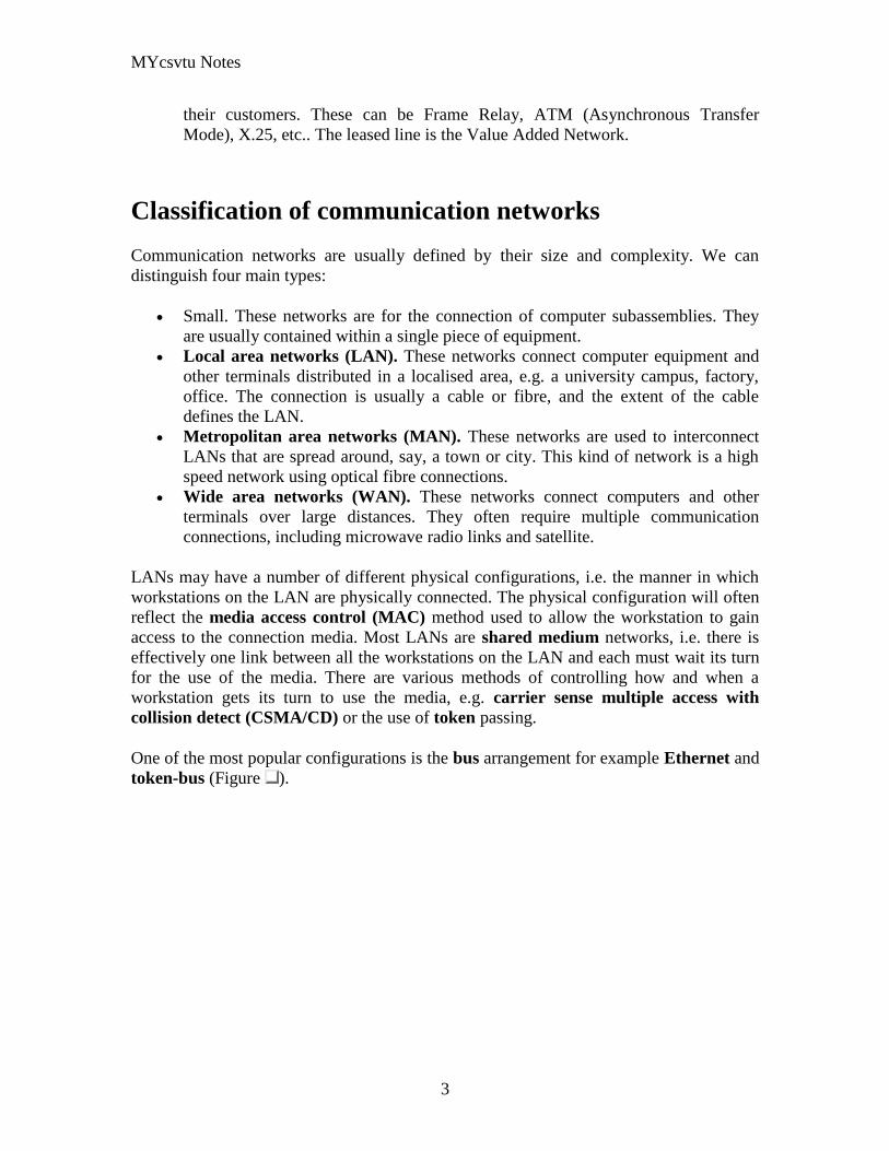
MYcsvtu Notes
3
their customers These can be Frame Relay ATM (Asynchronous Transfer
Mode) X25 etc The leased line is the Value Added Network
Classification of communication networks
Communication networks are usually defined by their size and complexity We can
distinguish four main types
Small These networks are for the connection of computer subassemblies They
are usually contained within a single piece of equipment
Local area networks (LAN) These networks connect computer equipment and
other terminals distributed in a localised area eg a university campus factory
office The connection is usually a cable or fibre and the extent of the cable
defines the LAN
Metropolitan area networks (MAN) These networks are used to interconnect
LANs that are spread around say a town or city This kind of network is a high
speed network using optical fibre connections
Wide area networks (WAN) These networks connect computers and other
terminals over large distances They often require multiple communication
connections including microwave radio links and satellite
LANs may have a number of different physical configurations ie the manner in which
workstations on the LAN are physically connected The physical configuration will often
reflect the media access control (MAC) method used to allow the workstation to gain
access to the connection media Most LANs are shared medium networks ie there is
effectively one link between all the workstations on the LAN and each must wait its turn
for the use of the media There are various methods of controlling how and when a
workstation gets its turn to use the media eg carrier sense multiple access with
collision detect (CSMACD) or the use of token passing
One of the most popular configurations is the bus arrangement for example Ethernet and
token-bus (Figure )
MYcsvtu Notes
4
Figure LAN bus arrangement
In this configuration all the workstations effectively hang off from one piece of wire
Another common configuration is a ring for example token-ring (Figure )
Figure LAN ring arrangement
A star configuration is not seldom used to interconnect workstations on a LAN Instead it
is used to interconnect LANs via an exchange or switch however emerging
asynchronous transfer mode (ATM) technology (and other high-speed networks) may
make the use of star configurations a more common occurrence (Figure )
MYcsvtu Notes
5
Figure LAN star arrangement
You may hear these configurations referred to as LAN topologies LAN segments may
be interconnected by use of a backbone LAN that allows communication between the
segments The segments help to localise traffic eg within an office or a single floor in a
building Each segment is a LAN in itself but is connected to the backbone via a bridge
(Figure )
Figure Backbone interconnecting LAN segments
MYcsvtu Notes
6
WANs often exploit public networks such as the public telephone system (Figure )
There are two types of public network
Public switched telephone network (PSTN) This is the ordinary telephone
system This system exists in all countries of the world It was designed
specifically for the transmission of voice communication Digital systems
employing this network must produce a voice-like signal and accept the low
transmission rates
Public switched data network (PSDN) This is a public network designed
specifically for the transmission of digital data They arose from privately owned
WANs that required higher performance than the PSTN Many countries of the
world are introducing PSDN services They can support much higher transmission
rates An integrated services digital network (ISDN) is the term given to all-
digital networks that can carry simultaneously voice and data communication and
offer additionally a variety of teletex services ISDN services are being introduced
all round the world and are indeed on offer in the UK
Figure WANs to interconnect LANs
MANs are now taking some of the roles that WANs once had in particular environments
for LAN LAN interconnection due to the high speeds that they offer compared to most
MYcsvtu Notes
7
PSTNs and PSDNs eg FDDI and DQDB offer 100Mbs whereas a PSTN line may
offer say 192Kbs with a fast modem
At the present time the worlds communication systems are in a state of flux Historically
digital computing equipment conformed to the requirements of the PSTN Now
increasingly analogue traffic such as voice and video is conforming to the requirements
of the PSDN
Public networks employ two types of switching Switching describes the method by
which the corresponders are connected A circuit switched network (CSN) establishes a
connection through the network that is then used exclusively by the two correspondents
(Of course only in 19th century telephone exchanges is the switching actually current
driven) The PSTN is a circuit switched network A packet switched network (PSN)
divides the message into packets that are addressed to the recipient The packets are then
forwarded through the network together with many other packets These are locally
distributed on arrival The Post Office is a packet switched network More relevantly
LAN communication is exclusively via a PSN The outstanding advantage of the PSN is
that the two correspondents can communicate at different rates permitting much more
efficient use of the communication channel
The Communications Channel
A communication channel can be simplex in which only one party can transmit full-
duplex in which both correspondents can transmit and receive simultaneously or half-
duplex in which the correspondents alternate between transmitting and receiving states
(such as conversing adults) Even though the channel might be capable of supporting full-
duplex communication if the corresponding entities are not capable of transmitting and
receiving simultaneously the communications system will be half-duplex (as in the
example of the conversing adults)
Communication between two entities can be considered either in-band or out-of-band
depending on context In-band communication is communication which occurs via the
primary channel between the communicating entities Out-of-band communication occurs
via an alternative channel which is not considered to be the primary channel between the
entities
Which channel is primary and which is an alternate depends on context and the existence
of an alternative channel In the case of a conversation between two people the primary
channel could consist of verbal communication while the alternate channel consists of
visual body language Of course if emotions rise these two channels might reverse roles
with body language becoming the primary channel
MYcsvtu Notes
8
Simplex communication
From Wikipedia the free encyclopedia
Jump to navigation search
Simplex communication is a name for a type of communication circuit There are two
(contradictory) definitions that have been used for the term In both cases the other
definition is referred to as half duplex
Contents
[hide]
1 One way at a time
2 One way only
o 21 Examples according to ANSI definition
3 References
4 See also
One way at a time
According to the ITU-T definition a simplex circuit is one where all signals can flow in
only one direction at a time This was also the way Western Union used the term when
describing the duplex and simplex capacity of their new transatlantic telegraph cable
completed between Newfoundland and the Azores in 1928[1]
The same definition for a
simplex radio channel was used by the National Fire Protection Association in 2002[2]
One way only
According to the ANSI definition a simplex circuit is one where all signals can flow in
only one direction These systems are often employed in broadcast networks where the
receivers do not need to send any data back to the transmitterbroadcaster
To put it simply you wont find your radio receiver actually sending out any information
all it does is receive so information moves one way only from the radio broadcasting
station to your radio receiver
Half-Duplex
MYcsvtu Notes
9
A simple illustration of a half-duplex communication system
A half-duplex system provides for communication in both directions but only one
direction at a time (not simultaneously) Typically once a party begins receiving a signal
it must wait for the transmitter to stop transmitting before replying
An example of a half-duplex system is a two-party system such as a walkie-talkie style
two-way radio wherein one must use Over or another previously designated command
to indicate the end of transmission and ensure that only one party transmits at a time
because both parties transmit on the same frequency A good analogy for a half-duplex
system would be a one lane road with traffic controllers at each end Traffic can flow in
both directions but only one direction at a time with this being regulated by the traffic
controllers
Note that this is one of two contradictory definitions for half-duplex This
definition matches the ANSI standard For more detail see Simplex
communication
Full-Duplex
A simple illustration of a full-duplex communication system
A full-duplex system allows communication in both directions and unlike half-duplex
allows this to happen simultaneously Land-line telephone networks are full-duplex since
they allow both callers to speak and be heard at the same time A good analogy for a full-
duplex system would be a two lane road with one lane for each direction
Examples Telephone Mobile Phone etc
MYcsvtu Notes
10
Two way radios can be for instance designed as full-duplex systems which transmit on
one frequency and receive on a different frequency This is also called frequency-division
duplex Frequency-division-duplex systems can be extended to farther distances using
pairs of simple repeater stations owing to the fact the communications transmitted on any
one frequency always travels in the same direction
Full-duplex Ethernet connections work by making simultaneous use of all four physical
pair of twisted cable (which are inside the insulation) where two pair are used for
receiving packets and two pair are using for sending packets to a directly connected
device This effectively makes the cable itself a collision-free environment and
theoretically doubles the maximum bandwidth that can be supported by the connection
Channel Characteristics
A communications channel may be described in terms of its characteristic properties
These channel characteristics includebandwidth (how much information can be
conveyed across the channel in a unit of time commonly expressed in bits per second or
bps7 ) quality (how reliably can the information be correctly conveyed across the
channel commonly in terms of bit error rate or BER8 ) and whether the channel is
dedicated (to a single source) or shared (by multiple sources)
Obviously a higher bandwidth is usually a good thing in a channel because it allows more
information to be conveyed per unit of time High bandwidths mean that more users can
share the channel depending on their means of accessing it High bandwidths also allow
more demanding applications (such as graphics) to be supported for each user of the
channel
The capability of a channel to be shared depends of course on the medium used A shared
channel could be likened to a school classroom where multiple students might attempt to
simultaneously catch the teachers attention by raising their hand the teacher must then
arbitrate between these conflicting requests allowing only one student to speak at a time
Reliability of communication is obviously important A low quality channel is prone to
distorting the messages it conveys a high quality channel preserves the integrity of the
messages it conveys Depending on the quality of the channel in use between
communicating entities the probability of the destination correctly receiving the message
from the source might be either very high or very low If the message is received
incorrectly it needs to be retransmitted
If the probability of receiving a message correctly across a channel is too low the system
(source channel message destination) must include mechanisms which overcome the
errors introduced by the low quality channel Otherwise no useful communication is
possible over that channel These mechanisms are embodied in the communication
protocols employed by the corresponding entities
MYcsvtu Notes
11
The effective bandwidth describes what an application experiences and depends on the
quality of service (QOS) provided by the channel For example modems scale back their
transmission speed based largely on their perception of channel quality in order to
optimally use the transmission medium
In general shared and reliable channels are more resource efficient than those which
enjoy neither of these characteristics Shared channels enjoy greater efficiency than
dedicated ones because most data communication is bursty in nature with long idle
periods punctuated by brief message transmissions Reliable channels are more efficient
than unreliable ones because retransmissions are not required as often (because there are
fewer transmission-induced errors)
The OSI Reference Model
The Open Systems Interconnect (OSI) reference model is commonly used to describe in
an abstract manner the functions involved in data communication This model originally
conceived in the International Organization for Standardization (ISO) defines data
communications functions in terms of layers
In the OSI reference model each layer is responsible for certain basic functions such as
getting data from one device to another or from one application on a computer to another
The functions at each layer both depend and build on the functions-called services-
provided by the layers below it Communication between peer entities at a given layer is
done via one or more protocols this communication is invoked via the interface with the
layer below
The OSI reference model is depicted in Table 01 Successful communication between
two applications depends on successful functions at all seven layers In terms of
implementation it is possible for some layers to be trivial in the end what is required
depends on the needs of the applications (and people) engaged in communication
Table 01 OSI Reference Model
Layer Title
7 Application
Higher Layers 6 Presentation
5 Session
4 Transport
MYcsvtu Notes
12
3 Network
Lower Layers 2 Data Link
1 Physical
We must emphasize that the definition of a layered data communication architecture is
only an abstraction The intent of this definition is to unambiguously describe the
functions involved in data communication in a way which allows different systems to be
compared The OSI reference model definition is intended to neither imply nor constrain
the implementation of any communication system
Although various companies and standards bodies have created different layered
communications models the OSI reference model remains the universally-accepted
common denominator for abstract definition Other models define the layer functions
somewhat differently and often have fewer than seven layers In some cases constituent
protocols were specified before the abstract models defining the end-to-end
communication
We will now review the functions of the OSI layers and some of the primary protocols at
each layer9
Layer 1 - The Physical Layer
The physical layer functions include all physical aspects of communicating between two
directly-connected physical entities Typically these physical properties include
electromechanical characteristics of the medium or link between the communicating
physical entities such as connectors voltages transmission frequencies etc This layer
summarizes the physics which underlie the communication path
The essential service provided by the physical layer consists of an unstructured bit
stream which can be used by higher layers to provide the basis for higher layer
communication services An example of a physical layer is the ink on paper used by this
book to convey information Another example is the radio frequencies used in a wireless
communications system
Layer 2 - The Data Link Layer
The data link layer accepts the unstructured bit stream provided by the physical layer and
provides reliable transfer of data between two directly-connected Layer 2 entities
Directly-connected means that the Layer 2 entities communication path does not
require another Layer 2 entity However this does not imply a dedicated path in the case
MYcsvtu Notes
13
of Ethernet many Layer 2 entities can be sharing a common (physical) medium such as a
coaxial cable or a 10BASE-T hub
Layer 2 functionality is limited in scope-delivery of messages over a local area It could
be likened to an intra-office correspondence between co-workers there is a need for
reliability but addressing is relatively simple Local area networks (LANs) operate at
Layer 2
The data link layer is itself conceptually subdivided into two sublayers-medium access
control and logical link control-which more specifically define the primary aspects of
data link layer functionality However this conceptual partitioning by the IEEE 802
committee is somewhat arbitrary and subject to debate
The MAC Sublayer
The medium access control (MAC) sublayer is closely associated with the physical layer
and defines the means by which the physical channel (medium) may be accessed It
coordinates the attempts to seize a shared channel by multiple MAC entities much as a
school teacher must arbitrate between pupils conflicting desires to speak The MAC layer
commonly provides a limited form of error control especially for any header information
which defines the MAC-level destination and higher-layer access mechanism
Ethernet (IEEE 8023) is a prime example of a shared medium with a defined MAC
sublayer functionality The shared medium in Ethernet has traditionally consisted of a
coaxial cable into which multiple entities were tapped as depicted in Figure 05
Although this topology still applies conceptually a hub and spoke medium is now
typically used in which the earlier coaxial cable has been physically collapsed into a hub
device
Figure 05 Ethernet MAC System
11
As a contention medium Ethernet defines how devices sense a channel for its
availability wait when it is busy seize the channel when it becomes available and back-
off for a random length of time following a collision with another simultaneously
MYcsvtu Notes
14
transmitting device On a shared channel such as Ethernet only a single entity can
transmit at a time or messages will be garbled
Not all shared channels involve contention A prime example of a contentionless shared
medium is token ring (IEEE 8025) in which control of the channel is rotated between
the devices sharing the channel in a deterministic round-robin manner Conceptually
control of the channel is given to the entity currently possessing a token If the device
has nothing to transmit it passes the token to the next device attached to the topological
ring depicted in Figure 06
Figure 06 Token Ring MAC System
11
IEEE-defined MAC sublayer addresses are six bytes long and permanently assigned to
each device typically called a network interface card orNIC The IEEE administers the
assignment of these addresses in blocks to manufacturers to assure the global uniqueness
that the MAC sublayer protocols rely on for plug Ocircn play network setup Each
manufacturer must assure individual device identifier uniqueness within their assigned
block
The LLC Sublayer
The logical link control (LLC) sublayer is responsible for reliable transfer of messages-
called frames or more formally link protocol data units (LPDUs)-between two directly-
connected Layer 2 entities Functions needed to support this reliable transfer include
framing (indicating where a Layer 2 message begins and ends) sequence control error
control and flow control
MYcsvtu Notes
15
The degree to which sequence error and flow control are provided by the LLC sublayer
is determined by whether the link protocol is connection-oriented or connectionless A
connectionless link protocol provides little if any support for these functions A
connection-oriented link might use a windowing technique for these functions in which
frames are individually numbered and acknowledged by their sequence number with
only a few such frames outstanding at any time
The connection-oriented functions of sequencing error and flow control provide a
foundation for services provided by higher layers As mentioned earlier not all layer or
sublayer functions are explicitly designed or implemented in any given system Provision
of these functions depends on the services required by higher layers
If the connection-oriented functions of the LLC sublayer are not implemented they must
be performed by higher layers for reliable end-to-end communication If these functions
are provided by several layers they might be somewhat redundant and add unnecessary
overhead (inefficiency) to the system In the worst case redundant provision of these
functions at multiple layers could serve cross purposes and actually degrade overall
system performance
An example of a connectionless LLC protocol is frame relay (T1617 618) which
defines point-to-point links with switches connecting individual links in a mesh topology
In a frame relay network endpoints are connected by a series of links and switches
Because frame relay is defined in terms of the links between frame relay access devices
(FRADs) and switches and between switches themselves it is an LLC protocol
Connectionless Layer 2 protocols are best suited for high quality transmission media
With high quality transmission media errors are rarely introduced in the transmission
between network layer entities and discovery of and recovery from errors is most
efficiently handled by the communicating hosts In this case it is better to move the
packets quickly across the traversed subnetworks from source to destination rather than
checking for errors at Layer 2
Frame relay is derived from the X25 (ISO 8208) protocol which spans Layers 2 and 3
X25 is a connection-oriented packet-switching technology which defines how
neighboring packet switches exchange data with one another in a reliable manner from
end-to-end Frame relay simply removes the connection-oriented functions of error and
sequence control however congestion control functions are provided in frame relay to
prevent the total traffic seen at any point in the network from overwhelming it
Connection-oriented Layer 2 protocols are best suited for low quality transmission media
where it is more efficient and cost-effective to discover and recover from errors as they
occur on each hop than to rely on the communicating hosts to perform error recovery
functions With ever-increasing quality of transmission facilities and decreasing costs of
computation capability at hosts the need for connection-oriented network layer protocols
is diminishing However X25 remains popular outside of North America where it has
been tariffed at levels which encourage its use
MYcsvtu Notes
16
End-to-end communications may be via shared or dedicated facilities or circuits Shared
facilities involve the use of packet switching technology to carry messages from end-to-
end messages are subdivided as necessary into packets which share physical and logical
channels with packets from various sources to various destinations Packet switching is
almost universally used in data communications because it is more efficient for the bursty
nature of data traffic
On the other hand some applications require dedicated facilities from end-to-end because
they are isochronous (eg voice) or bandwidth-intensive (eg large file transfer) This
mode of end-to-end circuit dedication is called circuit switched communication Because
the facilities are dedicated to a single user this tends to be much more expensive than the
packet switched mode of communication But some applications need it-it is an economic
trade-off
Dedicated circuits are a rather extreme form of connection-oriented protocol requiring
the same setup and tear-down phases prior to and following communication If the circuit
setup and tear-down is statically arranged (ie out-of-band) it is referred to as a
permanent virtual circuit or PVC If the circuit is dynamically setup and torn-down in-
band it is referred to as a switched virtual circuit or SVC
Layer 3 - The Network Layer
The network layer defines the functions necessary to support data communication
between indirectly-connected entities It provides the capability of forwarding messages
from one Layer 3 entity to another until the final destination is reached
The network layer introduces another layer of abstraction to the data communications
model It moves messages-called packets or more formally network protocol data units
(NPDUs)-between communicating Layer 3 entities-called end systems nodes or hosts
Network layer functions include route determination or routing and forwarding of
packets to their final destinations
In order to forward a packet to its destination host routing information must be provided
to theintermediate systems (ISs) or routers responsible for forwarding packets to their
respective destinations This routing information includes the address of the destination
which is contained in each packet The next hop to be traversed by the packet is
determined primarily by this destination address We will talk more about addressing and
routing in Chapter 1
This packet forwarding and routing is accomplished independent of both the media and
transmission types used at any step along the way The unimportance of local topology to
the network layer is demonstrated by the common use of cloud diagrams to depict
networks as in Figure 07 Since the network layer is concerned with getting packets
across many local networks called subnetworks its title would be more accurate if it
were the Internetwork Layer
MYcsvtu Notes
17
Figure 07 Network Layer ``Cloud
Diagram
11
The network layer functionality is global in scope-delivery of messages over a wide area
It could be likened to the postal system in which correspondence is passed from location
to location until it eventually reaches the destination address on the envelope10
The
network layer is the domain of wide area networks (WANs)
In order for routers to know how (ie on which link) to forward packets they must have
some knowledge of network topology This knowledge may be complete or partial and is
dynamically created and maintained via routing protocols used by routers to share their
knowledge of network topology with each other Routing is essentially the reduction of
global internetwork topology to local hop-by-hop routing decisions made
independently by each router
As with Layer 2 Layer 3 protocols may be connection-oriented or connectionless A
connection-oriented Layer 3 protocol such as X25 (ISO 8208) operates more statically
The basic idea is that an end-to-end route (X25 virtual connection) is established from
the originating data terminal equipment (DTE) to data communications equipment
(DCE) from DCE to DCE through the network then from the last DCE to the
terminating DTE this is the call setup Packets are then transmitted via this prearranged
route with all packets following the same path through the network Finally the route is
torn down (release) and packets cease flowing
X25 operation is like a phone call because it is a phone call X25 Layer 3 operation
assumes that a reliable connection-oriented service is provided by Layer 2 (also defined
by the X25 standard) although it does provide flow control via sequence numbers
Connectionless Layer 3 protocols such as the ever popular internet protocol (IP)(RFC11
791 and 792) and its ISO counterpart connectionless network protocol (CLNP) (ISO
MYcsvtu Notes
18
8473) route packets dynamically There is no prearranged path which is followed by
subsequent packets flowing from one host to another Instead each packet is individually
routed through a routing mesh there is no reason to believe that sequential packets
flowing between hosts will follow the same path So sequence errors may be introduced
at Layer 3 which must be corrected by a higher layer entity
Connectionless data packets are commonly referred to as datagrams and the service
provided by connectionless Layer 3 protocols is referred to as datagram service Stateless
datagram service is simpler for Layer 3 entities than connection-oriented network layer
services Because there is no state information to maintain dynamic routing protocols can
be used If a router fails during the dialogue between two communicating hosts
neighboring routers will discover this via the routing protocols and find alternate routes
which bypass the failed router
There seems to be a fair amount of ambiguity between the network layer and the LLC
sublayer Both can provide connection-oriented or connectionless services to higher
layers To a large extent if Layer 3 is explicitly implemented there is no need for an
LLC sublayer The primary difference is in scope-LLC addresses and protocols are
oriented toward a more local environment whereas network layer addresses and protocols
are global in scope
Excellent references to routing and forwarding of data packets can be found in [PERL92]
and [STEN95]
Layer 4 - The Transport Layer
The transport layer is concerned with getting Layer 4 messages-called segments or more
formally transport protocol data units (TPDUs) -from source to destination in a reliable
manner The perspective of Layer 4 is of end-to-end communications rather than the hop-
by-hop perspective of Layer 3 Layer 4 assumes that packets can be moved from network
entity to network entity eventually getting to the final destination host How this is
accomplished is of no concern to Layer 4 functionality
Like other layers transport layer protocols can be either connection-oriented or
connectionless depending on the services required by higher layers A common
implementation of Layers 3 and 4 involves a connection-oriented transport layer protocol
running over a connectionless network layer protocol such as the ubiquitous TCPIP
protocol suite In this instance the communicating hosts maintain state information on
communications with each other to determine when and what to send This state
information defines the connection between the communicating Layer 4 entities
The general idea here is that two communicating hosts need not be concerned with the
topology of the internetwork which lies between them They only need to know the state
of their pairwise communication If part of the intervening internetwork cloud suffers a
failure the Layer 3 entities (routers) will deal with it and recover dynamically Aside
MYcsvtu Notes
19
from potential retransmission of any lost segments the hosts Layer 4 entries do not have
to be at all concerned with routing and recovery activities at Layer 3
In the IP protocol suite the primary connectionless Layer 4 protocol is the User
Datagram Protocol (UDP)(RFC 768) which is carried by IP the primary connection-
oriented protocol is the Transmission Control Protocol (TCP)(RFC 793) The ISO world
defines five classes of transport layer protocol beginning with Class 0 (TP-0) for
connectionless operation and range up to Class 4 (TP-4)(ISO 8073) for connection-
oriented operation
Layer 5 - The Session Layer
The session layer provides a control structure for communication between applications
on hosts The communication at layer 5 is called a session which defines the relative
timing of communications between the hosts applications Synchronization of
communicating applications comes into play when coordinated timing of corresponding
events at the endpoints is imperative such as in financial transactions
Remember layers define communication functions not implementations It is unlikely
that a session layer would be explicitly implemented as a stand-alone program although
its functions would be implemented somewhere Session layer functions depend on the
reliability of communications between the endpoints and session layer functions must
therefore be implemented above Layer 4
Layer 6 - The Presentation Layer
The presentation layer performs any necessary data transformations or formatting
required by the end applications Functions provided by the presentation layer include
data compression file formatting and encryption Common data formatting is important
because it allows the same application file to be accessed by the application running on
different computer platforms This book is itself the product of an application running on
different platforms with common files being modified via these different platforms
Abstract Syntax Notation (ASN1) is commonly used to specify data values in a way
which allows processors to communicate independent of their varying native integer
sizes bit orderings (big or little endian) character sets etc ASN1 is a transfer syntax a
presentation layer formatting which appears frequently in the CDPD specification for
unambiguous definition of network management accounting limited size messaging and
other functions
An example of ASN1 encoding from an accounting Traffic Matrix Segment in the
CDPD specification is the following
MYcsvtu Notes
20
TrafficType = INTEGER
registration (0)
deregistration (1)
ip(2)
clnp(3)
Layer 7 - The Application Layer
The application layer provides the services which directly support an application running
on a host These services are directly accessible by an application via common well-
known application program interfaces (APIs) which can actually occur at many layers
Examples of layer 7 services include FTP (file transfer protocol) Telnet and SNMP
(simple network management protocol) Most network management activities are based
on the services provided by layer 7 application entities which in turn rely on lower layer
services to be able to perform their functions
7 Application ECHO ENRP FTP Gopher HTTP NFS RTSP SIP SMTP SNMP
SSH Telnet Whois XMPP
6 Presentation XDR ASN1 SMB AFP NCP
5 Session ASAP TLS SSL ISO 8327 CCITT X225 RPC NetBIOS ASP
4 Transport TCP UDP RTP SCTP SPX ATP IL
3 Network IP ICMP IGMP IPX OSPF RIP IGRP EIGRP ARP RARP X25
2 Data Link Ethernet Token ring HDLC Frame relay ISDN ATM 80211 WiFi
FDDI PPP
1 Physical 10BASE-T 100BASE-T 1000BASE-T SONETSDH G709 T-
carrierE-carrier various 80211 physical layers
The TCPIP Reference Model
The TCPIP reference model is the network model used in the current Internet
architecture [19] It has its origins back in the 1960s with the grandfather of the Internet
the ARPANET This was a research network sponsored by the Department of Defense in
the United States The following were seen as major design goals
ability to connect multiple networks together seamlessly
ability for connections to remain intact as long as the source and destination
machines were functioning
MYcsvtu Notes
21
to be built on flexible architecture
The reference model was named after two of its main protocols TCP (Transmission
Control Protocol) [12] and IP (Internet Protocol)
They choose to build a packet-switched network based on a connectionless internetwork
layer
Figure 21 TCPIP Network Protocol
A detailed description of the reference model is beyond the scope of this document and
project The basic idea of the networking system is to allow one application on a host
computer to talk to another application on a different host computer
The application forms its request then passes the packet down to the lower layers which
add their own control information either a header or a footer onto the packet Finally the
packet reaches the physical layer and is transmitted through the cable onto the destination
host The packet then travels up through the different layers with each layer reading
deciphering and removing the header or footer that was attached by its counterpart on the
originating computer Finally the packet arrives at the application it was destined for
Even though technically each layer communicates with the layer above or below it the
process can be viewed as one layer talking to its partner on the host as figure 21 shows
The Host-to-Network Layer
The Host-to-Network layer interfaces the TCPIP protocol stack to the physical network
The TCPIP reference model does not specify in any great detail the operation of this
layer except that the host has to connect to the network using some protocol so it can
send IP packets over it
As it is not officially defined it varies from implementation to implementation with
vendors supplying their own version
MYcsvtu Notes
22
The Network Layer
The job of the network layer is to inject packets into any network and have them travel
independently to the destination The layer defines IP (Internet Protocol) for its official
packet format and protocol Packet routing is a major job of this protocol
The Transport Layer
The transport layer is the interface between the application layer and the complex
hardware of the network It is designed to allow peer entities on the source and
destination hosts to carry on conversations
Data may be user data or control data Two modes are available full-duplex and half
duplex In full-duplex operation both sides can transmit and receive data simultaneously
whereas in half duplex a side can only send or receive at one time
Interaction between the transport layer and the layers immediately above and below are
shown in figure 22 Any program running in the application layer has the ability to send
a message using TCP or UDP which are the two protocols defined for the transport layer
The application can communicate with the TCP or the UDP service whichever it
requires Both the TCP and UDP communicate with the Internet Protocol in the internet
layer In all cases communication is a two way process The applications can read and
write to the transport layer The diagram only shows two protocols in the transport layer
TTCP will also reside in this layer between the other two protocols and function in the
same manner
Figure 22 Interaction with Application Transport and Internet Layers
A message to be sent originates in the application layer This is then passed down onto
the appropriate protocol in the transport layer These protocols add a header to the
message for the corresponding transport layer in the destination machine for purposes of
reassembling the message The segment is then passed onto the internet layer where the
Internet Protocol adds a further header Finally the segment is passed onto the physical
MYcsvtu Notes
23
layer a header and a trailer are added at this stage Figure 23 shows the structure of the
final segment being sent
Figure 23 Transmitted Segment from TCPIP Network
The Application Layer
The original TCPIP specification described a number of different applications that fit
into the top layer of the protocol stack These applications include Telnet FTP SMTP
and DNS
Telnet is a program that supports the TELNET [13] protocol over TCP TELNET is a
general two-way communication protocol that can be used to connect to another host and
run applications on that host remotely
FTP (File Transfer Protocol) [14] is a protocol that was originally designed to promote
the sharing of files among computer users It shields the user from the variations of file
storage on different architectures and allows for a reliable and efficient transfer of data
SMTP (Simple Mail Transport Protocol) [15] is the protocol used to transport electronic
mail from one computer to another through a series of other computers along the route
DNS [10] (Domain Name System) resolves the numerical address of a network node into
its textual name or vice-versa It would translate wwwyahoocom to 2047117771 to
allow the routing protocols to find the host that the packet is destined for
What is a Topology
The physical topology of a network refers to the configuration of cables computers and
other peripherals Physical topology should not be confused with logical topology which
is the method used to pass information between workstations Logical topology was
discussed in the Protocol chapter
Main Types of Physical Topologies
The following sections discuss the physical topologies used in networks and other related
topics
Linear Bus
MYcsvtu Notes
24
Star
Star-Wired Ring
Tree
Considerations When Choosing a Topology
Summary Chart
Linear Bus
A linear bus topology consists of a main run of cable with a terminator at each end (See
fig 1) All nodes (file server workstations and peripherals) are connected to the linear
cable Ethernet and LocalTalk networks use a linear bus topology
Fig 1 Linear Bus topology
Advantages of a Linear Bus Topology
Easy to connect a computer or peripheral to a linear bus
Requires less cable length than a star topology
Disadvantages of a Linear Bus Topology
Entire network shuts down if there is a break in the main cable
Terminators are required at both ends of the backbone cable
Difficult to identify the problem if the entire network shuts down
Not meant to be used as a stand-alone solution in a large building
Star
A star topology is designed with each node (file server workstations and peripherals)
connected directly to a central network hub or concentrator (See fig 2)
Data on a star network passes through the hub or concentrator before continuing to its
destination The hub or concentrator manages and controls all functions of the network It
also acts as a repeater for the data flow This configuration is common with twisted pair
cable however it can also be used with coaxial cable or fiber optic cable
MYcsvtu Notes
25
Fig 2 Star topology
Advantages of a Star Topology
Easy to install and wire
No disruptions to the network then connecting or removing devices
Easy to detect faults and to remove parts
Disadvantages of a Star Topology
Requires more cable length than a linear topology
If the hub or concentrator fails nodes attached are disabled
More expensive than linear bus topologies because of the cost of the
concentrators
The protocols used with star configurations are usually Ethernet or LocalTalk Token
Ring uses a similar topology called the star-wired ring
Star-Wired Ring
A star-wired ring topology may appear (externally) to be the same as a star topology
Internally the MAU (multistation access unit) of a star-wired ring contains wiring that
allows information to pass from one device to another in a circle or ring (See fig 3) The
Token Ring protocol uses a star-wired ring topology
Tree
A tree topology combines characteristics of linear bus and star topologies It consists of
groups of star-configured workstations connected to a linear bus backbone cable (See fig
MYcsvtu Notes
26
4) Tree topologies allow for the expansion of an existing network and enable schools to
configure a network to meet their needs
Fig 4 Tree topology
Advantages of a Tree Topology
Point-to-point wiring for individual segments
Supported by several hardware and software venders
Disadvantages of a Tree Topology
Overall length of each segment is limited by the type of cabling used
If the backbone line breaks the entire segment goes down
More difficult to configure and wire than other topologies
5-4-3 Rule
A consideration in setting up a tree topology using Ethernet protocol is the 5-4-3 rule
One aspect of the Ethernet protocol requires that a signal sent out on the network cable
reach every part of the network within a specified length of time Each concentrator or
repeater that a signal goes through adds a small amount of time This leads to the rule that
between any two nodes on the network there can only be a maximum of 5 segments
connected through 4 repeatersconcentrators In addition only 3 of the segments may be
populated (trunk) segments if they are made of coaxial cable A populated segment is one
which has one or more nodes attached to it In Figure 4 the 5-4-3 rule is adhered to The
MYcsvtu Notes
27
furthest two nodes on the network have 4 segments and 3 repeatersconcentrators
between them
This rule does not apply to other network protocols or Ethernet networks where all fiber
optic cabling or a combination of a fiber backbone with UTP cabling is used If there is a
combination of fiber optic backbone and UTP cabling the rule is simply translated to 7-
6-5 rule
] Mesh
Full
Fully Connected The type of network topology in which each of the nodes of the network is
connected to each of the other nodes in the network with a point-to-point link ndash
this makes it possible for data to be simultaneously transmitted from any single
node to all of the other nodes
Note The physical fully connected mesh topology is generally too costly and
complex for practical networks although the topology is used when there are only
a small number of nodes to be interconnected[3]
Partial
Partially Connected The type of network topology in which some of the nodes of the network are
connected to more than one other node in the network with a point-to-point link ndash
this makes it possible to take advantage of some of the redundancy that is
provided by a physical fully connected mesh topology without the expense and
complexity required for a connection between every node in the network
Note In most practical networks that are based upon the physical partially
connected mesh topology all of the data that is transmitted between nodes in the
network takes the shortest path between nodes except in the case of a failure or
break in one of the links in which case the data takes an alternate path to the
destination ndash this implies that the nodes of the network possess some type of
logical routing algorithm to determine the correct path to use at any particular
time
[edit] Hybrid Network Topologies
The hybrid topology is a type of network topology that is composed of one or more
interconnections of two or more networks that are based upon different physical
topologies or a type of network topology that is composed of one or more
interconnections of two or more networks that are based upon the same physical
topology but where the physical topology of the network resulting from such an
interconnection does not meet the definition of the original physical topology of the
interconnected networks (eg the physical topology of a network that would result from
an interconnection of two or more networks that are based upon the physical star
topology might create a hybrid topology which resembles a mixture of the physical star
MYcsvtu Notes
28
and physical bus topologies or a mixture of the physical star and the physical tree
topologies depending upon how the individual networks are interconnected while the
physical topology of a network that would result from an interconnection of two or more
networks that are based upon the physical distributed bus network retains the topology of
a physical distributed bus network)
Star-Bus A type of network topology in which the central nodes of one or more individual
networks that are based upon the physical star topology are connected together
using a common bus network whose physical topology is based upon the
physical linear bus topology the endpoints of the common bus being terminated
with the characteristic impedance of the transmission medium where required ndash
eg two or more hubs connected to a common backbone with drop cables
through the port on the hub that is provided for that purpose (eg a properly
configured uplink port) would comprise the physical bus portion of the physical
star-bus topology while each of the individual hubs combined with the
individual nodes which are connected to them would comprise the physical star
portion of the physical star-bus topology
Star-of-Stars
Hierarchical Star A type of network topology that is composed of an interconnection of individual
networks that are based upon the physical star topology connected together in a
hierarchical fashion to form a more complex network ndash eg a top level central
node which is the hub of the top level physical star topology and to which other
second level central nodes are attached as the spoke nodes each of which in
turn may also become the central nodes of a third level physical star topology
Notes 1) The physical hierarchical star topology is not a combination of the physical
linear bus and the physical star topologies as cited in some texts as there is no
common linear bus within the topology although the top level hub which is the
beginning of the physical hierarchical star topology may be connected to the
backbone of another network such as a common carrier which is topologically
not considered to be a part of the local network ndash if the top level central node is
connected to a backbone that is considered to be a part of the local network then
the resulting network topology would be considered to be a hybrid topology that
is a mixture of the topology of the backbone network and the physical hierarchical
star topology
2) The physical hierarchical star topology is also sometimes incorrectly referred
to as a physical tree topology since its physical topology is hierarchical however
the physical hierarchical star topology does not have a structure that is determined
by a branching factor as is the case with the physical tree topology and therefore
nodes may be added to or removed from any node that is the hub of one of the
individual physical star topology networks within a network that is based upon the
physical hierarchical star topology
3) The physical hierarchical star topology is commonly used in outside plant
(OSP) cabling to connect various buildings to a central connection facility which
MYcsvtu Notes
29
may also house the demarcation point for the connection to the data transmission
facilities of a common carrier and in inside plant (ISP) cabling to connect
multiple wiring closets within a building to a common wiring closet within the
same building which is also generally where the main backbone or trunk that
connects to a larger network if any enters the building
Star-wired Ring A type of hybrid physical network topology that is a combination of the physical
star topology and the physical ring topology the physical star portion of the
topology consisting of a network in which each of the nodes of which the network
is composed are connected to a central node with a point-to-point link in a hub
and spoke fashion the central node being the hub and the nodes that are
attached to the central node being the spokes (eg a collection of point-to-point
links from the peripheral nodes that converge at a central node) in a fashion that is
identical to the physical star topology while the physical ring portion of the
topology consists of circuitry within the central node which routes the signals on
the network to each of the connected nodes sequentially in a circular fashion
Note In an 8025 Token Ring network the central node is called a Multistation
Access Unit (MAU)
Hybrid Mesh A type of hybrid physical network topology that is a combination of the physical
partially connected topology and one or more other physical topologies the mesh
portion of the topology consisting of redundant or alternate connections between
some of the nodes in the network ndash the physical hybrid mesh topology is
commonly used in networks which require a high degree of availability
Considerations When Choosing a Topology
Money A linear bus network may be the least expensive way to install a network
you do not have to purchase concentrators
Length of cable needed The linear bus network uses shorter lengths of cable
Future growth With a star topology expanding a network is easily done by
adding another concentrator
Cable type The most common cable in schools is unshielded twisted pair which
is most often used with star topologies
Summary Chart
Common Cable Common Protocol
Linear Bus Twisted Pair
Coaxial
Ethernet
LocalTalk
MYcsvtu Notes
30
Fiber
Star Twisted Pair
Fiber
Ethernet
LocalTalk
Star-Wired Ring Twisted Pair Token Ring
Tree
Twisted Pair
Coaxial
Fiber
Ethernet
Internet vs Web
The Internet and the World Wide Web are not synonymous the Internet is a collection of
interconnected computer networks linked by copper wires fiber-optic cables wireless
connections etc the Web is a collection of interconnected documents and other
resources linked by hyperlinks and URLs The World Wide Web is accessible via the
Internet as are many other services including e-mail file sharing and others described
below
The best way to define and distinguish between these terms is to understand the Internet
protocol suite This collection of protocols is organized into layers such that each layer
provides the foundation and the services required by the layer above In this conception
the term Internet refers to computer networks that all communicate with IP (Internet
protocol) and TCP (transfer control protocol) Once this networking structure is
established then other protocols can run ―on top These other protocols are sometimes
called services or applications Hypertext transfer protocol or HTTP is an application
layer protocol that links billions of files together into the World Wide Web
Common uses of the Internet
The World Wide Web
Through keyword-driven Internet research using search engines like Google
millions worldwide have easy instant access to a vast and diverse amount of
online information Compared to encyclopedias and traditional libraries the
World Wide Web has enabled a sudden and extreme decentralization of
information and data
Many individuals and some companies and groups have adopted the use of Web logs or
blogs which are largely used as easily-updatable online diaries Some commercial
organizations encourage staff to fill them with advice on their areas of specialization in
the hope that visitors will be impressed by the expert knowledge and free information
and be attracted to the corporation as a result One example of this practice is Microsoft
MYcsvtu Notes
31
whose product developers publish their personal blogs in order to pique the publics
interest in their work
For more information on the distinction between the World Wide Web and the Internet
itself mdash as in everyday use the two are sometimes confused mdash see Dark internet where
this is discussed in more detail
Remote access
The Internet allows computer users to connect to other computers and information stores
easily wherever they may be across the world They may do this with or without the use
of security authentication and encryption technologies depending on the requirements
This is encouraging new ways of working from home collaboration and information
sharing in many industries An accountant sitting at home can audit the books of a
company based in another country on a server situated in a third country that is remotely
maintained by IT specialists in a fourth These accounts could have been created by
home-working book-keepers in other remote locations based on information e-mailed to
them from offices all over the world Some of these things were possible before the
widespread use of the Internet but the cost of private leased lines would have made
many of them infeasible in practice
An office worker away from his desk perhaps the other side of the world on a business
trip or a holiday can open a remote desktop session into his normal office PC using a
secure Virtual Private Network (VPN) connection via the Internet This gives him
complete access to all his normal files and data including e-mail and other applications
while he is away
This concept is also referred to by some network security people as the Virtual Private
Nightmare because it extends the secure perimeter of a corporate network into its
employees homes this has been the source of some notable security breaches but also
provides security for the workers
Functions
File-sharing
Instant messaging
Internet fax
Search engine
World Wide Web
MYcsvtu Notes
32
Intranets
What are Intranets
bull Intranet is Intra+ Net so an Intranet is an internal or private Internet used strictly
within the confines of a company university or organization Inter means
between or among hence the difference between the Internet and an Intranet
Some formal definitions of Intranets
bull Brown amp Duguid ―Intranets help present and
circulate boundary objects
bull Choo Detlor amp Turnbull ―Intranetshellip support the creation sharing and use of
knowledge
bull Stenmark ―Intranets are organizationally
restricted
A technical definition
bull An Intranet is a network based on the internet TCPIP open standard An intranet
belongs to an organization and is designed to be accessible only by the
organizations members employees or others with authorization An intranets
Web site looks and act just like other Web sites but has a firewall surrounding it
to fend off unauthorized users
Design Of Intranets
Steps
bull Analyze the organizationlsquos information ecology
bull Identify the typical problems experienced by users
bull Analyze the information behaviors of these set of users
bull Create value added processes to resolve the problems of users and to improve the
Information Ecology
Value Added Processes
bull Intranets may be designed to improve the organizational information ecology
MYcsvtu Notes
33
bull Intranets provide a unified information space in which users can communicate
and collaborate with others
bull intranet applications and services may add value by supporting the organizationlsquos
knowledge creating and decision making process
Two Models of Online Environments
Centralized
Distributed
Centralized Environments
bull Before the web the centralized model was all we had (examples include
CompuServe Prodigy)
bull On the web centralized models include site-based services such as Yahoo
bull Most (all) college and university services are offered using the centralized
model
MYcsvtu Notes
34
bull But centralized environments are static inflexible expensive
Distributed Environments
bull The World Wide Web is an example of a distributed environment
bull Resources access are not centralized but scattered around the world
ndash Resources in the form of a network of connected (via DNS) web servers
ndash Access in the form of a network of connected (via DNS) internet service
providers
ndash Users in the form of individualized and connected (via HTTP) web
browsers
bull The big issue ndash integration ndash that is making different systems work together
Design Principles
Network Design Principles
ndash Specifies how networks differ from traditional learning
ndash The idea is that each principle confers an advantage over non-network
systems
ndash Can be used as a means of evaluating new technology
1 Decentralize
ndash Centralized networks have a characteristic starlsquo shape
bull Some entities have many connections
bull The vast majority have few
bull Eg broadcast network teacher in a classroom
ndash Decentralized networks form a mesh
bull The weight of connections flow is distributed
bull Balanced load = more stable
bull Foster connections between entities fill outlsquo the star
Distribute
ndash Network entities reside in different physical locations
bull Reduces risk of network failure
bull Reduces need for major infrastructure such as powerful servers
large bandwidth massive storage
ndash Examples
bull Peer-to-peer networks such as Kazaa Gnutella
bull Content syndication networks such as RSS
ndash Emphasis is on sharing not copying
bull Locallsquo copies are temporary
MYcsvtu Notes
35
Computer Graphics
Computer Graphics is about animation (films)
Games are very important in Computer Graphics
Medical Imaging is another driving force
Computer Aided Design too
Graphics Definitions
bull Point
ndash a location in space 2D or 3D
ndash sometimes denotes one pixel
bull Line
ndash straight path connecting two points
ndash infinitesimal width consistent density
ndash beginning and end on points
bull Vertex
ndash point in 3D
bull Edge
ndash line in 3D connecting two vertices
bull PolygonFaceFacet
ndash arbitrary shape formed by connected vertices
ndash fundamental unit of 3D computer graphics
bull Raster
ndash derived from TV systems for a row of pixels
ndash commonly referred to as a scanline
ndash does influence algorithms ndash reducing memory requirements parallelism
etc
ndash is the derivation of rasterization scan-line algorithms
Displays
bull Most desktop displays use a cathode ray tube (CRT) while portable computing
devices such as laptops incorporate liquid crystal display (LCD)
bull Because of their slimmer design and smaller energy consumption monitors using
LCD technologies are beginning to replace the venerable CRT on many desktops
Cathode-Ray Tubes
MYcsvtu Notes
36
bull Classical output device is a monitor
bull Cathode-Ray Tube (CRT)
ndash Invented by Karl Ferdinand Braun (1897)
ndash Beam of electrons directed from cathode (-)to phosphor-coated
(fluorescent) screen (anode (+))
ndash Directed by magnetic focusing and deflection coils (anodes) in vacuum
filled tube
ndash Phosphor emits photon of light when hit by an electron of varied
persistence (long 15-20 ms for texts short lt 1ms for animation)
ndash Refresh rate (50-60 Hz 72-76 Hz) to avoid flicker trail
ndash Phosphors are organic compounds characterized by their persistence and
their color (blue red green)
Cathode-Ray Tubes
bull Cathode-Ray Tube (CRT)
ndash Horizontal deflection and vertical deflection direct the electron beam to
any point on the screen
ndash Intensity knob regulates the flow of electrons by controlling the voltage at
the control grid (high voltage reduces the electron density and thus
brightness)
ndash Accelerating voltage from positive coating inside screen (anode screen) or
an accelerating anode
bull Image maintenance
ndash Charge distribution to store picture information
OR
ndash Refresh CRT refreshes the display constantly to maintain phosphor glow
Cathode-Ray Tubes
bullCathode-Ray Tube (CRT)
ndash Horizontal deflection and vertical deflection direct the electron beam to any point
on the screen
ndash Intensity knob regulates the flow of electrons by controlling the voltage at the
control grid (high voltage reduces the electron density and thus brightness)
ndash Accelerating voltage from positive coating inside screen (anode screen) or an
accelerating anode
bullImage maintenance
ndash Charge distribution to store picture information
OR
ndash Refresh CRT refreshes the display constantly to maintain phosphor glow
bull Characteristics of Cathode-Ray Tube (CRT)
MYcsvtu Notes
37
ndash Intensity is proportional to the number of electrons repelled in beam per
second (brightness)
ndash Resolution is the maximum number of points that can be displayed
without overlap is expressed as number of horizontal points by number of
vertical points points are called pixels (picture elements) example
resolution 1024 x 768 pixels Typical resolution is 1280 x 1024 pixels
bull High-definition systems high resolution systems
bull Focusing
ndash Focusing forces the electron beam to converge to a point on the monitor
screen
ndash Can be electrostatic (lens) or magnetic (field)
bull Deflection
ndash Deflection directs the electron beam horizontally andor vertically to any
point on the screen
ndash Can be controlled by electric (deflection plates slide 9) or magnetic fields
(deflection coils slide 5)
ndash Magnetic coils two pairs (topbottom leftright) of tube neck
ndash Electric plates two pairs (horizontal vertical)
Raster-scan Displays
bullVideo displays can be either raster-scan or random-scan displays
bullRaster-scan display is the most common type of monitor using a CRT
bullThe electron beam scans the screen from top to bottom one row at a time Each row is
called a scan line
bullThe electron beam is turned on and off to produce a collection of dots painted one row at
a time These will form the image
bullA raster is a matrix of pixels covering the screen area and is composed of raster lines
Raster-scan Displays
MYcsvtu Notes
38
Raster-scan Displays
bullThe image is stored in a frame buffer containing the total screen area and where each
memory location corresponds to a pixel
bullIn a monochrome system each bit is 1 or 0 for the corresponding pixel to be on or off
(bitmap)
bullThe display processor scans the frame buffer to turn electron beam onoff depending if
the bit is 1 or 0
bullFor color monitors the frame buffer also contains the color of each pixel (color buffer)
as well as other characteristics of the image (gray scale hellip) 8 bitspixel 0255
(pixmap)
bullDepth of the buffer area is the number of bits per pixel (bit planes) up to 24
bullExamples television panels printers PC monitors (99 of raster-scan)
Raster-scan Displays
bullRefresh rate 24 is a minimum to avoid flicker corresponding to 24 Hz (1 Hz = 1 refresh
per second)
bullCurrent raster-scan displays have a refresh rate of at least 60 frames (60 Hz) per second
up to 120 (120 Hz)
bullUses large memory 640x480 307200 bits 38 kB
bullRefresh procedure
MYcsvtu Notes
39
ndashHorizontal retrace ndash beam returns to left of screen
ndashVertical retrace ndash bean returns to top left corner of screen
ndashInterlaced refresh ndash display first even-numbered lines then odd-numbered lines
permits to see the image in half the time
useful for slow refresh rates (30 Hz shows as 60 Hz)
Random-scan Displays
bullRandom scan systems are also called vector stroke-writing or calligraphic displays
bullThe electron beam directly draws the picture in any specified order
bullA pen plotter is an example of such a system
bullPicture is stored in a display list refresh display file vector file or display program as a
set of line drawing commands
bullRefreshes by scanning the list 30 to 60 times per second
bullMore suited for line-drawing applications such as architecture and manufacturing
Random-scan Displays
bullAdvantages
ndashHigh resolution
ndashEasy animation
ndashRequires little memory
bullDisadvantages
ndashRequires intelligent electron beam (processor controlled)
ndashLimited screen density limited to simple line-based images
ndashLimited color capability
bullImproved in the 1960lsquos by the Direct View Storage Tube (DVST) from Tektronix
Color CRT Monitor
Uses different phosphors a combination of Red Green and Blue to produce any color
Two methods
Random scan uses beam penetration
2 layers (Red Green) phosphors low speed electrons excite Red high speed electrons
excite Green interrmediate speed excite both to get yellow and orange Color is
controlled by electron beam voltage
Only produces a restricted set of colors
Raster scan uses a shadow mask with three electron guns Red Green and Blue (RGB
color model) Color is produced by adjusting the intensity level of each electron beam
Produces a wide range of colors from 8 to several millions
Raster scan
Most common as found in televisions
Beam scanned left to right flicked back to rescan from top to bottom then repeated
Repeated at 30Hz per frame sometimes higher to reduce flicker Interlacing scanning
MYcsvtu Notes
40
odd lines in whole screen then even lines is also used to reduce flicker Can also use
high-persistence phosphor to reduce flicker but causes image smearing especially with
significant animation
Resolution typically 512x512 but high-quality screens are available (and becoming more
common) at up to approximately 1600x1200 pixels Sun workstations have screens of
1192x980 pixels
Black amp white screens can display grayscale by varying the intensity of the electron
beam
Colour is achieved using three electron guns which hit red green or blue phosphors
Combining these colours can produce many others including white (all on) Phosphor
dots focused using a shadow mask - makes colour screens lower resolution than
monochrome
Alternative approach beam penetration Special phosphor glows a different colour
depending on intensity of beam
Colour or intensity at pixel held by computerlsquos video card 1 bitpixel can store offon
information hence only black ampwhite More bitspixel give rise to more colour
possibilities eg 8 bitspixel gives rise to 2^8=256 possible colours at any one time
Random Scan (Directed-beam refresh vector display)
Instead of scanning the whole display sequentially and horizontally the random scan
draws the lines to be displayed directly Screen update at gt30Hz to reduce flicker
Jaggies not found and higher resolutions possible (up to 4096x4096 pixels) Colour
achieved using beam penetration generally of poorer quality Eye strain and fatigue still
a problem and vector displays are more expensive
Direct view storage tube (DVST)
Used a lot in analogue storage oscilloscopes
Similar to random scan crt but image maintained by flood guns - no flicker Can be
incrementally updated but not selectively erased image has to be redrawn on completely
erased screen High resolution (typically 4096x3120 pixels) but low contrast low
brightness and difficulty in displaying colour
What is a Multimedia System
bull A system that involves
ndash generation
ndash representation
ndash storage
ndash transmission
ndash search and retrieval
ndash delivery
MYcsvtu Notes
41
of multimedia information
productionauthoring tools
compression and formats
file system design
networking issues
database management
server design streaming
Multimedia System Architecture
Information management subsystem Presentation Query
Storage subsystem Efficiently stored
amp retrieved
Network subsystem Delivery
Adaptation in Multimedia Systems
bull Multimedia systems can profit a lot from personalization
ndash User behavior
ndash User properties
bull Adaptation
ndash Models
ndash Mechanisms
Multimedia in a mobile environment
MYcsvtu Notes
42
bull Applications
ndash Emergency response systems mobile commerce phone service
entertainment games
What is Sound
A ripple is a pressure wave in water created by an object striking the water
Sound is a pressure wave in air created for example by an object such as a string
or our vocal cords vibrating Dark here represents more pressure light represents
less
MYcsvtu Notes
43
Sine Waves Form Pure Tones
This simple sound wave is a Sine Wave a Pure tone produced by a simple vibration
Sine Wave Sample Tone
This can be represented graphically as shown above
Converting Pressure into Voltage
The pressure wave of sound moves a diaphragm in the microphone which produces a
voltage proportional to the pressure of the sound wave at each instant
Animation
MYcsvtu Notes
44
bull Animation is the rapid display of a sequence of images of 2-D artwork or model
positions in order to create an illusion of movement It is an optical illusion of
motion due to the phenomenon of persistence of vision This could be anything
from a flip book to a motion picture film Animation deals with the generation
sequencing and display a set of images which is called frames to create an effect
of visual change or motion similar to a movie film
bull Animation is used in those instance where videography is not possible
Hardware Requirement For Animation
bull Image Generation Tools amp Devices
bull Computer monitors with image display Capability
Software Requirement For Animation
bull Animation creating software
bull Screen Capture Software
bull Animation Clips
bull Software support For High Resolution
bull Recording amp Playback Capability
bull Transition effect
Early animation
There is no single person that can be considered the creator of the art of animation as
there were several people doing several projects which could be considered various types
of animation all around the same time (Short hand-drawn animation scenes could be
presented with the Phenakistoscope the Zoetrope and other optical toys already in the
early 1800s)
The following is a brief listing on those who are often acknowledged as significant to the
development of animation Note that this list is by no means a comprehensive list of
contributors to early animation
Georges Meacuteliegraves was a creator of special effect films such as A Trip to the Moon He
used many techniques ndash one of which was to stop the camera rolling change something
in the scene and then continue rolling the film This is a very similar idea to that of stop-
motion animation Meacuteliegraves accidentally happened upon the technique when his camera
broke down while shooting a bus driving by When the camera was fixed a horse
happened to be passing by just as Meacuteliegraves continued to film The result was that the bus
appeared to change into a horse
MYcsvtu Notes
45
Fantasmagorie by Emile Cohl 1908
Eacutemile Cohl began drawing cartoon strips and created a film in 1908 called
Fantasmagorie The film largely consisted of a stick figure moving about and
encountering all manner of morphing objects such as a wine bottle that transforms into a
flower There were also sections of live action where the animatorlsquos hands would enter
the scene The film was created by drawing each frame on paper and then shooting each
frame onto negative film which gave the picture a blackboard look
Winsor McCay created detailed animations that required a team of artists and painstaking
attention for detail Each frame was drawn on paper requiring backgrounds to be
redrawn as well characters to be animated His films such as Gertie the Dinosaur (1914)
and The Sinking of the Lusitania (1918) were of an impressive scale although The
Sinking of the Lusitania used cels
In 1919 Otto Messmer created the character of Felix the cat for Pat Sullivans animation
studios The importance of Felix lies in the characters strong personality created largely
through gesture and actions
Animation techniques
Animation techniques are incredibly varied and difficult to categorize Techniques are
often related or combined The following is a brief on common types of animation
Again this list is by no means comprehensive
Traditional animation
An example of traditional animation a horse animated by rotoscoping from Edweard
Muybridges 19th century photos
Main article Traditional animation
MYcsvtu Notes
46
Also called cel animation the frames of a traditionally animated movie are hand-drawn
The drawings are traced or copied onto transparent acetate sheets called cels which are
then placed over a painted background and photographed one by one on a rostrum
camera Nowadays the use of cels (and cameras) is mostly obsolete since the drawings
are scanned into computers and digitally transferred directly to 35 mm film The look
of traditional cel animation is still preserved and the character animators work has
remained essentially the same over the past 70 years Because of the digital influence
over modern cel animation it is also known as tradigital animation
Examples The Lion King Spirited Away Les Triplettes de Belleville
Full animation The most common style in animation known for its realistic and often very detailed art
Examples All Disney feature length animated films The Secret of NIMH The Iron Giant
Limited animation A cheaper process of making animated cartoons that does not follow a realistic
approach
Examples The Flintstones Yellow Submarine
Rubber hose The characters are usually cartoony and the animators have a lot of artistic freedom as
rubber hose animations dont have to follow the laws of physics and anatomy in the same
degree as the other main styles in animation
Examples Early Mickey Mouse cartoons Ren and Stimpy Popeye
Rotoscoping A technique where animators trace live action movement frame by frame for use in
animated films
Examples Gullivers Travels American Pop
Stop motion
Stop-motion animation is any type of animation which requires the animator to physically
alter the scene shoot a frame again alter the scene and shoot a frame and so on to create
the animation There are many different types of stop-motion animation some noteable
examples are listed below
Clay animation
MYcsvtu Notes
47
A clay animation scene from a TV commercial
Often abbreviated to claymation this is a type of stop-motion animation using
figures made of clay or a similar malleable material The figures may have an
armature or wire frame inside of them similar to puppet animation (below)
Alternatively the figures may be made entirely of clay such as in the films of
Bruce Bickford where clay creatures morph into a variety of different shapes
Examples Wallace and Gromit Dimensions of Dialogue by Jan Švankmajer The
Amazing Mr Bickford The Trap Door
Cutout animation In this type of stop-motion animation the animation is formed by moving 2-
dimensional pieces of material such as paper or cloth
Examples the animated sequences of Monty Pythons Flying Circus (often
referred to as Dada animation named after the Dada art movement[citation needed]
)
Tale of Tales early episodes of South Park
Silhouette animation A type of cutout animation where the viewer only sees black silhouettes
Example The Adventures of Prince Achmed the worlds oldest surviving
animated feature film from 1926
Graphic animation
Model animation In this form of animation model animated characters interact with and are a part
of the live-action world
Examples The films of Ray Harryhausen (Jason and the Argonauts) and Willis
OBrien (King Kong)
Go motion
Object animation
Pixilation Examples Neighbours
Puppet animation Puppet animation typically involves puppet figures interacting with each other in
a constructed environment in contrast to the real-world interaction in model
MYcsvtu Notes
48
animation (above) The puppets generally have an armature inside of them to
keep them still and steady as well as constraining them to move at particular
joints
Examples The Nightmare Before Christmas Robot Chicken The Tale of the Fox
Brickfilm
Puppetoon
Computer animation
A short gif animation
Like stop motion computer animation encompasses a variety of techniques the unifying
idea being that the animation is created digitally on a computer
2D animation Figures are created andor edited on the computer using 2D bitmap graphics or
created and edited using 2D vector graphics This includes automated
computerized versions of traditional animation techniques such as of tweening
morphing onion skinning and interpolated rotoscoping
Examples A Scanner Darkly Jib Jab
Analog computer animation
Flash animation
PowerPoint animation
A completely synthetic computer-generated scene
3D animation
MYcsvtu Notes
49
Figures are created in the computer using polygons To allow these meshes to
move they are given a digital armature (sculpture) This process is called rigging
Various other techniques can be applied such as mathematical functions
(gravity) simulated fur or hair effects such as fire and water and the use of
motion capture to name but a few
Examples The Incredibles Shrek
Cel-shaded animation
Morph target animation
Skeletal animation
Motion capture
Crowd simulation
Less common techniques
Drawn on film animation A technique where footage is produced by creating the
images directly on film stock
Paint-on-glass animationA technique for making animated films by manipulating slow-
drying oil paints on sheets of glass
Pinscreen animation Makes use of a screen filled with movable pins which can be
moved in or out by pressing an object onto the screen The screen is lit from the side so
that the pins cast shadows The technique has been used to create animated films with a
range of textural effects difficult to achieve with traditional cel animation
Sand animation Sand is moved around on a backlighted or frontlighted piece of glass to
create each frame for an animated film
Multimedia
Multimedia (Lat Multum + Medium) is media that uses multiple forms of information
content and information processing (eg text audio graphics animation video
interactivity) to inform or entertain the (user) audience Multimedia also refers to the use
of (but not limited to) electronic media to store and experience multimedia content
Multimedia is similar to traditional mixed media in fine art but with a broader scope The
term rich media is synonymous for interactive multimedia
Categorization
Multimedia may be broadly divided into linear and non-linear categories Linear active
content progresses without any navigation control for the viewer such as a cinema
presentation Non-linear content offers user interactivity to control progress as used with
MYcsvtu Notes
50
a computer game or used in self-paced computer based training Non-linear content is
also known as hypermedia content
Multimedia presentations can be live or recorded A recorded presentation may allow
interactivity via a navigation system A live multimedia presentation may allow
interactivity via interaction with the presenter or performer
There are 2 basic way to represent some information
Unimedium Presentation
Multimedia Presentation
In case of computer system the commonly used medioa for the purpose of storage
access and transmission of information are
bull Text
bull Graphics
bull Animation
bull Audio
bull Video
Multimedia Computer System require
bull Faster CPU
bull Larger Storage Devices
bull Larger Main Memory
bull Good Graphics Terminal
bull IO devices required to play an audio associated with the program
Transmission Mode
bull Asynchronous
bull Synchronous
bull Isochronous
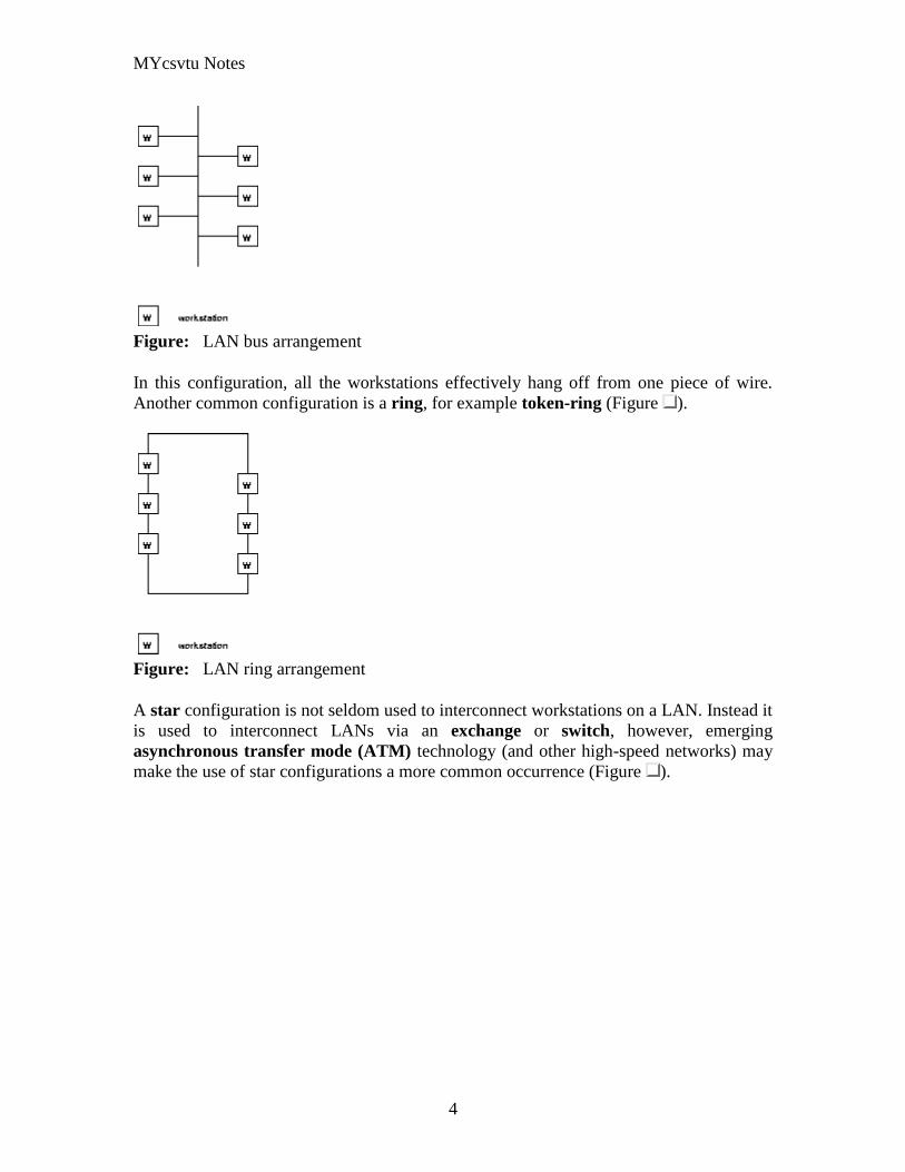
MYcsvtu Notes
4
Figure LAN bus arrangement
In this configuration all the workstations effectively hang off from one piece of wire
Another common configuration is a ring for example token-ring (Figure )
Figure LAN ring arrangement
A star configuration is not seldom used to interconnect workstations on a LAN Instead it
is used to interconnect LANs via an exchange or switch however emerging
asynchronous transfer mode (ATM) technology (and other high-speed networks) may
make the use of star configurations a more common occurrence (Figure )
MYcsvtu Notes
5
Figure LAN star arrangement
You may hear these configurations referred to as LAN topologies LAN segments may
be interconnected by use of a backbone LAN that allows communication between the
segments The segments help to localise traffic eg within an office or a single floor in a
building Each segment is a LAN in itself but is connected to the backbone via a bridge
(Figure )
Figure Backbone interconnecting LAN segments
MYcsvtu Notes
6
WANs often exploit public networks such as the public telephone system (Figure )
There are two types of public network
Public switched telephone network (PSTN) This is the ordinary telephone
system This system exists in all countries of the world It was designed
specifically for the transmission of voice communication Digital systems
employing this network must produce a voice-like signal and accept the low
transmission rates
Public switched data network (PSDN) This is a public network designed
specifically for the transmission of digital data They arose from privately owned
WANs that required higher performance than the PSTN Many countries of the
world are introducing PSDN services They can support much higher transmission
rates An integrated services digital network (ISDN) is the term given to all-
digital networks that can carry simultaneously voice and data communication and
offer additionally a variety of teletex services ISDN services are being introduced
all round the world and are indeed on offer in the UK
Figure WANs to interconnect LANs
MANs are now taking some of the roles that WANs once had in particular environments
for LAN LAN interconnection due to the high speeds that they offer compared to most
MYcsvtu Notes
7
PSTNs and PSDNs eg FDDI and DQDB offer 100Mbs whereas a PSTN line may
offer say 192Kbs with a fast modem
At the present time the worlds communication systems are in a state of flux Historically
digital computing equipment conformed to the requirements of the PSTN Now
increasingly analogue traffic such as voice and video is conforming to the requirements
of the PSDN
Public networks employ two types of switching Switching describes the method by
which the corresponders are connected A circuit switched network (CSN) establishes a
connection through the network that is then used exclusively by the two correspondents
(Of course only in 19th century telephone exchanges is the switching actually current
driven) The PSTN is a circuit switched network A packet switched network (PSN)
divides the message into packets that are addressed to the recipient The packets are then
forwarded through the network together with many other packets These are locally
distributed on arrival The Post Office is a packet switched network More relevantly
LAN communication is exclusively via a PSN The outstanding advantage of the PSN is
that the two correspondents can communicate at different rates permitting much more
efficient use of the communication channel
The Communications Channel
A communication channel can be simplex in which only one party can transmit full-
duplex in which both correspondents can transmit and receive simultaneously or half-
duplex in which the correspondents alternate between transmitting and receiving states
(such as conversing adults) Even though the channel might be capable of supporting full-
duplex communication if the corresponding entities are not capable of transmitting and
receiving simultaneously the communications system will be half-duplex (as in the
example of the conversing adults)
Communication between two entities can be considered either in-band or out-of-band
depending on context In-band communication is communication which occurs via the
primary channel between the communicating entities Out-of-band communication occurs
via an alternative channel which is not considered to be the primary channel between the
entities
Which channel is primary and which is an alternate depends on context and the existence
of an alternative channel In the case of a conversation between two people the primary
channel could consist of verbal communication while the alternate channel consists of
visual body language Of course if emotions rise these two channels might reverse roles
with body language becoming the primary channel
MYcsvtu Notes
8
Simplex communication
From Wikipedia the free encyclopedia
Jump to navigation search
Simplex communication is a name for a type of communication circuit There are two
(contradictory) definitions that have been used for the term In both cases the other
definition is referred to as half duplex
Contents
[hide]
1 One way at a time
2 One way only
o 21 Examples according to ANSI definition
3 References
4 See also
One way at a time
According to the ITU-T definition a simplex circuit is one where all signals can flow in
only one direction at a time This was also the way Western Union used the term when
describing the duplex and simplex capacity of their new transatlantic telegraph cable
completed between Newfoundland and the Azores in 1928[1]
The same definition for a
simplex radio channel was used by the National Fire Protection Association in 2002[2]
One way only
According to the ANSI definition a simplex circuit is one where all signals can flow in
only one direction These systems are often employed in broadcast networks where the
receivers do not need to send any data back to the transmitterbroadcaster
To put it simply you wont find your radio receiver actually sending out any information
all it does is receive so information moves one way only from the radio broadcasting
station to your radio receiver
Half-Duplex
MYcsvtu Notes
9
A simple illustration of a half-duplex communication system
A half-duplex system provides for communication in both directions but only one
direction at a time (not simultaneously) Typically once a party begins receiving a signal
it must wait for the transmitter to stop transmitting before replying
An example of a half-duplex system is a two-party system such as a walkie-talkie style
two-way radio wherein one must use Over or another previously designated command
to indicate the end of transmission and ensure that only one party transmits at a time
because both parties transmit on the same frequency A good analogy for a half-duplex
system would be a one lane road with traffic controllers at each end Traffic can flow in
both directions but only one direction at a time with this being regulated by the traffic
controllers
Note that this is one of two contradictory definitions for half-duplex This
definition matches the ANSI standard For more detail see Simplex
communication
Full-Duplex
A simple illustration of a full-duplex communication system
A full-duplex system allows communication in both directions and unlike half-duplex
allows this to happen simultaneously Land-line telephone networks are full-duplex since
they allow both callers to speak and be heard at the same time A good analogy for a full-
duplex system would be a two lane road with one lane for each direction
Examples Telephone Mobile Phone etc
MYcsvtu Notes
10
Two way radios can be for instance designed as full-duplex systems which transmit on
one frequency and receive on a different frequency This is also called frequency-division
duplex Frequency-division-duplex systems can be extended to farther distances using
pairs of simple repeater stations owing to the fact the communications transmitted on any
one frequency always travels in the same direction
Full-duplex Ethernet connections work by making simultaneous use of all four physical
pair of twisted cable (which are inside the insulation) where two pair are used for
receiving packets and two pair are using for sending packets to a directly connected
device This effectively makes the cable itself a collision-free environment and
theoretically doubles the maximum bandwidth that can be supported by the connection
Channel Characteristics
A communications channel may be described in terms of its characteristic properties
These channel characteristics includebandwidth (how much information can be
conveyed across the channel in a unit of time commonly expressed in bits per second or
bps7 ) quality (how reliably can the information be correctly conveyed across the
channel commonly in terms of bit error rate or BER8 ) and whether the channel is
dedicated (to a single source) or shared (by multiple sources)
Obviously a higher bandwidth is usually a good thing in a channel because it allows more
information to be conveyed per unit of time High bandwidths mean that more users can
share the channel depending on their means of accessing it High bandwidths also allow
more demanding applications (such as graphics) to be supported for each user of the
channel
The capability of a channel to be shared depends of course on the medium used A shared
channel could be likened to a school classroom where multiple students might attempt to
simultaneously catch the teachers attention by raising their hand the teacher must then
arbitrate between these conflicting requests allowing only one student to speak at a time
Reliability of communication is obviously important A low quality channel is prone to
distorting the messages it conveys a high quality channel preserves the integrity of the
messages it conveys Depending on the quality of the channel in use between
communicating entities the probability of the destination correctly receiving the message
from the source might be either very high or very low If the message is received
incorrectly it needs to be retransmitted
If the probability of receiving a message correctly across a channel is too low the system
(source channel message destination) must include mechanisms which overcome the
errors introduced by the low quality channel Otherwise no useful communication is
possible over that channel These mechanisms are embodied in the communication
protocols employed by the corresponding entities
MYcsvtu Notes
11
The effective bandwidth describes what an application experiences and depends on the
quality of service (QOS) provided by the channel For example modems scale back their
transmission speed based largely on their perception of channel quality in order to
optimally use the transmission medium
In general shared and reliable channels are more resource efficient than those which
enjoy neither of these characteristics Shared channels enjoy greater efficiency than
dedicated ones because most data communication is bursty in nature with long idle
periods punctuated by brief message transmissions Reliable channels are more efficient
than unreliable ones because retransmissions are not required as often (because there are
fewer transmission-induced errors)
The OSI Reference Model
The Open Systems Interconnect (OSI) reference model is commonly used to describe in
an abstract manner the functions involved in data communication This model originally
conceived in the International Organization for Standardization (ISO) defines data
communications functions in terms of layers
In the OSI reference model each layer is responsible for certain basic functions such as
getting data from one device to another or from one application on a computer to another
The functions at each layer both depend and build on the functions-called services-
provided by the layers below it Communication between peer entities at a given layer is
done via one or more protocols this communication is invoked via the interface with the
layer below
The OSI reference model is depicted in Table 01 Successful communication between
two applications depends on successful functions at all seven layers In terms of
implementation it is possible for some layers to be trivial in the end what is required
depends on the needs of the applications (and people) engaged in communication
Table 01 OSI Reference Model
Layer Title
7 Application
Higher Layers 6 Presentation
5 Session
4 Transport
MYcsvtu Notes
12
3 Network
Lower Layers 2 Data Link
1 Physical
We must emphasize that the definition of a layered data communication architecture is
only an abstraction The intent of this definition is to unambiguously describe the
functions involved in data communication in a way which allows different systems to be
compared The OSI reference model definition is intended to neither imply nor constrain
the implementation of any communication system
Although various companies and standards bodies have created different layered
communications models the OSI reference model remains the universally-accepted
common denominator for abstract definition Other models define the layer functions
somewhat differently and often have fewer than seven layers In some cases constituent
protocols were specified before the abstract models defining the end-to-end
communication
We will now review the functions of the OSI layers and some of the primary protocols at
each layer9
Layer 1 - The Physical Layer
The physical layer functions include all physical aspects of communicating between two
directly-connected physical entities Typically these physical properties include
electromechanical characteristics of the medium or link between the communicating
physical entities such as connectors voltages transmission frequencies etc This layer
summarizes the physics which underlie the communication path
The essential service provided by the physical layer consists of an unstructured bit
stream which can be used by higher layers to provide the basis for higher layer
communication services An example of a physical layer is the ink on paper used by this
book to convey information Another example is the radio frequencies used in a wireless
communications system
Layer 2 - The Data Link Layer
The data link layer accepts the unstructured bit stream provided by the physical layer and
provides reliable transfer of data between two directly-connected Layer 2 entities
Directly-connected means that the Layer 2 entities communication path does not
require another Layer 2 entity However this does not imply a dedicated path in the case
MYcsvtu Notes
13
of Ethernet many Layer 2 entities can be sharing a common (physical) medium such as a
coaxial cable or a 10BASE-T hub
Layer 2 functionality is limited in scope-delivery of messages over a local area It could
be likened to an intra-office correspondence between co-workers there is a need for
reliability but addressing is relatively simple Local area networks (LANs) operate at
Layer 2
The data link layer is itself conceptually subdivided into two sublayers-medium access
control and logical link control-which more specifically define the primary aspects of
data link layer functionality However this conceptual partitioning by the IEEE 802
committee is somewhat arbitrary and subject to debate
The MAC Sublayer
The medium access control (MAC) sublayer is closely associated with the physical layer
and defines the means by which the physical channel (medium) may be accessed It
coordinates the attempts to seize a shared channel by multiple MAC entities much as a
school teacher must arbitrate between pupils conflicting desires to speak The MAC layer
commonly provides a limited form of error control especially for any header information
which defines the MAC-level destination and higher-layer access mechanism
Ethernet (IEEE 8023) is a prime example of a shared medium with a defined MAC
sublayer functionality The shared medium in Ethernet has traditionally consisted of a
coaxial cable into which multiple entities were tapped as depicted in Figure 05
Although this topology still applies conceptually a hub and spoke medium is now
typically used in which the earlier coaxial cable has been physically collapsed into a hub
device
Figure 05 Ethernet MAC System
11
As a contention medium Ethernet defines how devices sense a channel for its
availability wait when it is busy seize the channel when it becomes available and back-
off for a random length of time following a collision with another simultaneously
MYcsvtu Notes
14
transmitting device On a shared channel such as Ethernet only a single entity can
transmit at a time or messages will be garbled
Not all shared channels involve contention A prime example of a contentionless shared
medium is token ring (IEEE 8025) in which control of the channel is rotated between
the devices sharing the channel in a deterministic round-robin manner Conceptually
control of the channel is given to the entity currently possessing a token If the device
has nothing to transmit it passes the token to the next device attached to the topological
ring depicted in Figure 06
Figure 06 Token Ring MAC System
11
IEEE-defined MAC sublayer addresses are six bytes long and permanently assigned to
each device typically called a network interface card orNIC The IEEE administers the
assignment of these addresses in blocks to manufacturers to assure the global uniqueness
that the MAC sublayer protocols rely on for plug Ocircn play network setup Each
manufacturer must assure individual device identifier uniqueness within their assigned
block
The LLC Sublayer
The logical link control (LLC) sublayer is responsible for reliable transfer of messages-
called frames or more formally link protocol data units (LPDUs)-between two directly-
connected Layer 2 entities Functions needed to support this reliable transfer include
framing (indicating where a Layer 2 message begins and ends) sequence control error
control and flow control
MYcsvtu Notes
15
The degree to which sequence error and flow control are provided by the LLC sublayer
is determined by whether the link protocol is connection-oriented or connectionless A
connectionless link protocol provides little if any support for these functions A
connection-oriented link might use a windowing technique for these functions in which
frames are individually numbered and acknowledged by their sequence number with
only a few such frames outstanding at any time
The connection-oriented functions of sequencing error and flow control provide a
foundation for services provided by higher layers As mentioned earlier not all layer or
sublayer functions are explicitly designed or implemented in any given system Provision
of these functions depends on the services required by higher layers
If the connection-oriented functions of the LLC sublayer are not implemented they must
be performed by higher layers for reliable end-to-end communication If these functions
are provided by several layers they might be somewhat redundant and add unnecessary
overhead (inefficiency) to the system In the worst case redundant provision of these
functions at multiple layers could serve cross purposes and actually degrade overall
system performance
An example of a connectionless LLC protocol is frame relay (T1617 618) which
defines point-to-point links with switches connecting individual links in a mesh topology
In a frame relay network endpoints are connected by a series of links and switches
Because frame relay is defined in terms of the links between frame relay access devices
(FRADs) and switches and between switches themselves it is an LLC protocol
Connectionless Layer 2 protocols are best suited for high quality transmission media
With high quality transmission media errors are rarely introduced in the transmission
between network layer entities and discovery of and recovery from errors is most
efficiently handled by the communicating hosts In this case it is better to move the
packets quickly across the traversed subnetworks from source to destination rather than
checking for errors at Layer 2
Frame relay is derived from the X25 (ISO 8208) protocol which spans Layers 2 and 3
X25 is a connection-oriented packet-switching technology which defines how
neighboring packet switches exchange data with one another in a reliable manner from
end-to-end Frame relay simply removes the connection-oriented functions of error and
sequence control however congestion control functions are provided in frame relay to
prevent the total traffic seen at any point in the network from overwhelming it
Connection-oriented Layer 2 protocols are best suited for low quality transmission media
where it is more efficient and cost-effective to discover and recover from errors as they
occur on each hop than to rely on the communicating hosts to perform error recovery
functions With ever-increasing quality of transmission facilities and decreasing costs of
computation capability at hosts the need for connection-oriented network layer protocols
is diminishing However X25 remains popular outside of North America where it has
been tariffed at levels which encourage its use
MYcsvtu Notes
16
End-to-end communications may be via shared or dedicated facilities or circuits Shared
facilities involve the use of packet switching technology to carry messages from end-to-
end messages are subdivided as necessary into packets which share physical and logical
channels with packets from various sources to various destinations Packet switching is
almost universally used in data communications because it is more efficient for the bursty
nature of data traffic
On the other hand some applications require dedicated facilities from end-to-end because
they are isochronous (eg voice) or bandwidth-intensive (eg large file transfer) This
mode of end-to-end circuit dedication is called circuit switched communication Because
the facilities are dedicated to a single user this tends to be much more expensive than the
packet switched mode of communication But some applications need it-it is an economic
trade-off
Dedicated circuits are a rather extreme form of connection-oriented protocol requiring
the same setup and tear-down phases prior to and following communication If the circuit
setup and tear-down is statically arranged (ie out-of-band) it is referred to as a
permanent virtual circuit or PVC If the circuit is dynamically setup and torn-down in-
band it is referred to as a switched virtual circuit or SVC
Layer 3 - The Network Layer
The network layer defines the functions necessary to support data communication
between indirectly-connected entities It provides the capability of forwarding messages
from one Layer 3 entity to another until the final destination is reached
The network layer introduces another layer of abstraction to the data communications
model It moves messages-called packets or more formally network protocol data units
(NPDUs)-between communicating Layer 3 entities-called end systems nodes or hosts
Network layer functions include route determination or routing and forwarding of
packets to their final destinations
In order to forward a packet to its destination host routing information must be provided
to theintermediate systems (ISs) or routers responsible for forwarding packets to their
respective destinations This routing information includes the address of the destination
which is contained in each packet The next hop to be traversed by the packet is
determined primarily by this destination address We will talk more about addressing and
routing in Chapter 1
This packet forwarding and routing is accomplished independent of both the media and
transmission types used at any step along the way The unimportance of local topology to
the network layer is demonstrated by the common use of cloud diagrams to depict
networks as in Figure 07 Since the network layer is concerned with getting packets
across many local networks called subnetworks its title would be more accurate if it
were the Internetwork Layer
MYcsvtu Notes
17
Figure 07 Network Layer ``Cloud
Diagram
11
The network layer functionality is global in scope-delivery of messages over a wide area
It could be likened to the postal system in which correspondence is passed from location
to location until it eventually reaches the destination address on the envelope10
The
network layer is the domain of wide area networks (WANs)
In order for routers to know how (ie on which link) to forward packets they must have
some knowledge of network topology This knowledge may be complete or partial and is
dynamically created and maintained via routing protocols used by routers to share their
knowledge of network topology with each other Routing is essentially the reduction of
global internetwork topology to local hop-by-hop routing decisions made
independently by each router
As with Layer 2 Layer 3 protocols may be connection-oriented or connectionless A
connection-oriented Layer 3 protocol such as X25 (ISO 8208) operates more statically
The basic idea is that an end-to-end route (X25 virtual connection) is established from
the originating data terminal equipment (DTE) to data communications equipment
(DCE) from DCE to DCE through the network then from the last DCE to the
terminating DTE this is the call setup Packets are then transmitted via this prearranged
route with all packets following the same path through the network Finally the route is
torn down (release) and packets cease flowing
X25 operation is like a phone call because it is a phone call X25 Layer 3 operation
assumes that a reliable connection-oriented service is provided by Layer 2 (also defined
by the X25 standard) although it does provide flow control via sequence numbers
Connectionless Layer 3 protocols such as the ever popular internet protocol (IP)(RFC11
791 and 792) and its ISO counterpart connectionless network protocol (CLNP) (ISO
MYcsvtu Notes
18
8473) route packets dynamically There is no prearranged path which is followed by
subsequent packets flowing from one host to another Instead each packet is individually
routed through a routing mesh there is no reason to believe that sequential packets
flowing between hosts will follow the same path So sequence errors may be introduced
at Layer 3 which must be corrected by a higher layer entity
Connectionless data packets are commonly referred to as datagrams and the service
provided by connectionless Layer 3 protocols is referred to as datagram service Stateless
datagram service is simpler for Layer 3 entities than connection-oriented network layer
services Because there is no state information to maintain dynamic routing protocols can
be used If a router fails during the dialogue between two communicating hosts
neighboring routers will discover this via the routing protocols and find alternate routes
which bypass the failed router
There seems to be a fair amount of ambiguity between the network layer and the LLC
sublayer Both can provide connection-oriented or connectionless services to higher
layers To a large extent if Layer 3 is explicitly implemented there is no need for an
LLC sublayer The primary difference is in scope-LLC addresses and protocols are
oriented toward a more local environment whereas network layer addresses and protocols
are global in scope
Excellent references to routing and forwarding of data packets can be found in [PERL92]
and [STEN95]
Layer 4 - The Transport Layer
The transport layer is concerned with getting Layer 4 messages-called segments or more
formally transport protocol data units (TPDUs) -from source to destination in a reliable
manner The perspective of Layer 4 is of end-to-end communications rather than the hop-
by-hop perspective of Layer 3 Layer 4 assumes that packets can be moved from network
entity to network entity eventually getting to the final destination host How this is
accomplished is of no concern to Layer 4 functionality
Like other layers transport layer protocols can be either connection-oriented or
connectionless depending on the services required by higher layers A common
implementation of Layers 3 and 4 involves a connection-oriented transport layer protocol
running over a connectionless network layer protocol such as the ubiquitous TCPIP
protocol suite In this instance the communicating hosts maintain state information on
communications with each other to determine when and what to send This state
information defines the connection between the communicating Layer 4 entities
The general idea here is that two communicating hosts need not be concerned with the
topology of the internetwork which lies between them They only need to know the state
of their pairwise communication If part of the intervening internetwork cloud suffers a
failure the Layer 3 entities (routers) will deal with it and recover dynamically Aside
MYcsvtu Notes
19
from potential retransmission of any lost segments the hosts Layer 4 entries do not have
to be at all concerned with routing and recovery activities at Layer 3
In the IP protocol suite the primary connectionless Layer 4 protocol is the User
Datagram Protocol (UDP)(RFC 768) which is carried by IP the primary connection-
oriented protocol is the Transmission Control Protocol (TCP)(RFC 793) The ISO world
defines five classes of transport layer protocol beginning with Class 0 (TP-0) for
connectionless operation and range up to Class 4 (TP-4)(ISO 8073) for connection-
oriented operation
Layer 5 - The Session Layer
The session layer provides a control structure for communication between applications
on hosts The communication at layer 5 is called a session which defines the relative
timing of communications between the hosts applications Synchronization of
communicating applications comes into play when coordinated timing of corresponding
events at the endpoints is imperative such as in financial transactions
Remember layers define communication functions not implementations It is unlikely
that a session layer would be explicitly implemented as a stand-alone program although
its functions would be implemented somewhere Session layer functions depend on the
reliability of communications between the endpoints and session layer functions must
therefore be implemented above Layer 4
Layer 6 - The Presentation Layer
The presentation layer performs any necessary data transformations or formatting
required by the end applications Functions provided by the presentation layer include
data compression file formatting and encryption Common data formatting is important
because it allows the same application file to be accessed by the application running on
different computer platforms This book is itself the product of an application running on
different platforms with common files being modified via these different platforms
Abstract Syntax Notation (ASN1) is commonly used to specify data values in a way
which allows processors to communicate independent of their varying native integer
sizes bit orderings (big or little endian) character sets etc ASN1 is a transfer syntax a
presentation layer formatting which appears frequently in the CDPD specification for
unambiguous definition of network management accounting limited size messaging and
other functions
An example of ASN1 encoding from an accounting Traffic Matrix Segment in the
CDPD specification is the following
MYcsvtu Notes
20
TrafficType = INTEGER
registration (0)
deregistration (1)
ip(2)
clnp(3)
Layer 7 - The Application Layer
The application layer provides the services which directly support an application running
on a host These services are directly accessible by an application via common well-
known application program interfaces (APIs) which can actually occur at many layers
Examples of layer 7 services include FTP (file transfer protocol) Telnet and SNMP
(simple network management protocol) Most network management activities are based
on the services provided by layer 7 application entities which in turn rely on lower layer
services to be able to perform their functions
7 Application ECHO ENRP FTP Gopher HTTP NFS RTSP SIP SMTP SNMP
SSH Telnet Whois XMPP
6 Presentation XDR ASN1 SMB AFP NCP
5 Session ASAP TLS SSL ISO 8327 CCITT X225 RPC NetBIOS ASP
4 Transport TCP UDP RTP SCTP SPX ATP IL
3 Network IP ICMP IGMP IPX OSPF RIP IGRP EIGRP ARP RARP X25
2 Data Link Ethernet Token ring HDLC Frame relay ISDN ATM 80211 WiFi
FDDI PPP
1 Physical 10BASE-T 100BASE-T 1000BASE-T SONETSDH G709 T-
carrierE-carrier various 80211 physical layers
The TCPIP Reference Model
The TCPIP reference model is the network model used in the current Internet
architecture [19] It has its origins back in the 1960s with the grandfather of the Internet
the ARPANET This was a research network sponsored by the Department of Defense in
the United States The following were seen as major design goals
ability to connect multiple networks together seamlessly
ability for connections to remain intact as long as the source and destination
machines were functioning
MYcsvtu Notes
21
to be built on flexible architecture
The reference model was named after two of its main protocols TCP (Transmission
Control Protocol) [12] and IP (Internet Protocol)
They choose to build a packet-switched network based on a connectionless internetwork
layer
Figure 21 TCPIP Network Protocol
A detailed description of the reference model is beyond the scope of this document and
project The basic idea of the networking system is to allow one application on a host
computer to talk to another application on a different host computer
The application forms its request then passes the packet down to the lower layers which
add their own control information either a header or a footer onto the packet Finally the
packet reaches the physical layer and is transmitted through the cable onto the destination
host The packet then travels up through the different layers with each layer reading
deciphering and removing the header or footer that was attached by its counterpart on the
originating computer Finally the packet arrives at the application it was destined for
Even though technically each layer communicates with the layer above or below it the
process can be viewed as one layer talking to its partner on the host as figure 21 shows
The Host-to-Network Layer
The Host-to-Network layer interfaces the TCPIP protocol stack to the physical network
The TCPIP reference model does not specify in any great detail the operation of this
layer except that the host has to connect to the network using some protocol so it can
send IP packets over it
As it is not officially defined it varies from implementation to implementation with
vendors supplying their own version
MYcsvtu Notes
22
The Network Layer
The job of the network layer is to inject packets into any network and have them travel
independently to the destination The layer defines IP (Internet Protocol) for its official
packet format and protocol Packet routing is a major job of this protocol
The Transport Layer
The transport layer is the interface between the application layer and the complex
hardware of the network It is designed to allow peer entities on the source and
destination hosts to carry on conversations
Data may be user data or control data Two modes are available full-duplex and half
duplex In full-duplex operation both sides can transmit and receive data simultaneously
whereas in half duplex a side can only send or receive at one time
Interaction between the transport layer and the layers immediately above and below are
shown in figure 22 Any program running in the application layer has the ability to send
a message using TCP or UDP which are the two protocols defined for the transport layer
The application can communicate with the TCP or the UDP service whichever it
requires Both the TCP and UDP communicate with the Internet Protocol in the internet
layer In all cases communication is a two way process The applications can read and
write to the transport layer The diagram only shows two protocols in the transport layer
TTCP will also reside in this layer between the other two protocols and function in the
same manner
Figure 22 Interaction with Application Transport and Internet Layers
A message to be sent originates in the application layer This is then passed down onto
the appropriate protocol in the transport layer These protocols add a header to the
message for the corresponding transport layer in the destination machine for purposes of
reassembling the message The segment is then passed onto the internet layer where the
Internet Protocol adds a further header Finally the segment is passed onto the physical
MYcsvtu Notes
23
layer a header and a trailer are added at this stage Figure 23 shows the structure of the
final segment being sent
Figure 23 Transmitted Segment from TCPIP Network
The Application Layer
The original TCPIP specification described a number of different applications that fit
into the top layer of the protocol stack These applications include Telnet FTP SMTP
and DNS
Telnet is a program that supports the TELNET [13] protocol over TCP TELNET is a
general two-way communication protocol that can be used to connect to another host and
run applications on that host remotely
FTP (File Transfer Protocol) [14] is a protocol that was originally designed to promote
the sharing of files among computer users It shields the user from the variations of file
storage on different architectures and allows for a reliable and efficient transfer of data
SMTP (Simple Mail Transport Protocol) [15] is the protocol used to transport electronic
mail from one computer to another through a series of other computers along the route
DNS [10] (Domain Name System) resolves the numerical address of a network node into
its textual name or vice-versa It would translate wwwyahoocom to 2047117771 to
allow the routing protocols to find the host that the packet is destined for
What is a Topology
The physical topology of a network refers to the configuration of cables computers and
other peripherals Physical topology should not be confused with logical topology which
is the method used to pass information between workstations Logical topology was
discussed in the Protocol chapter
Main Types of Physical Topologies
The following sections discuss the physical topologies used in networks and other related
topics
Linear Bus
MYcsvtu Notes
24
Star
Star-Wired Ring
Tree
Considerations When Choosing a Topology
Summary Chart
Linear Bus
A linear bus topology consists of a main run of cable with a terminator at each end (See
fig 1) All nodes (file server workstations and peripherals) are connected to the linear
cable Ethernet and LocalTalk networks use a linear bus topology
Fig 1 Linear Bus topology
Advantages of a Linear Bus Topology
Easy to connect a computer or peripheral to a linear bus
Requires less cable length than a star topology
Disadvantages of a Linear Bus Topology
Entire network shuts down if there is a break in the main cable
Terminators are required at both ends of the backbone cable
Difficult to identify the problem if the entire network shuts down
Not meant to be used as a stand-alone solution in a large building
Star
A star topology is designed with each node (file server workstations and peripherals)
connected directly to a central network hub or concentrator (See fig 2)
Data on a star network passes through the hub or concentrator before continuing to its
destination The hub or concentrator manages and controls all functions of the network It
also acts as a repeater for the data flow This configuration is common with twisted pair
cable however it can also be used with coaxial cable or fiber optic cable
MYcsvtu Notes
25
Fig 2 Star topology
Advantages of a Star Topology
Easy to install and wire
No disruptions to the network then connecting or removing devices
Easy to detect faults and to remove parts
Disadvantages of a Star Topology
Requires more cable length than a linear topology
If the hub or concentrator fails nodes attached are disabled
More expensive than linear bus topologies because of the cost of the
concentrators
The protocols used with star configurations are usually Ethernet or LocalTalk Token
Ring uses a similar topology called the star-wired ring
Star-Wired Ring
A star-wired ring topology may appear (externally) to be the same as a star topology
Internally the MAU (multistation access unit) of a star-wired ring contains wiring that
allows information to pass from one device to another in a circle or ring (See fig 3) The
Token Ring protocol uses a star-wired ring topology
Tree
A tree topology combines characteristics of linear bus and star topologies It consists of
groups of star-configured workstations connected to a linear bus backbone cable (See fig
MYcsvtu Notes
26
4) Tree topologies allow for the expansion of an existing network and enable schools to
configure a network to meet their needs
Fig 4 Tree topology
Advantages of a Tree Topology
Point-to-point wiring for individual segments
Supported by several hardware and software venders
Disadvantages of a Tree Topology
Overall length of each segment is limited by the type of cabling used
If the backbone line breaks the entire segment goes down
More difficult to configure and wire than other topologies
5-4-3 Rule
A consideration in setting up a tree topology using Ethernet protocol is the 5-4-3 rule
One aspect of the Ethernet protocol requires that a signal sent out on the network cable
reach every part of the network within a specified length of time Each concentrator or
repeater that a signal goes through adds a small amount of time This leads to the rule that
between any two nodes on the network there can only be a maximum of 5 segments
connected through 4 repeatersconcentrators In addition only 3 of the segments may be
populated (trunk) segments if they are made of coaxial cable A populated segment is one
which has one or more nodes attached to it In Figure 4 the 5-4-3 rule is adhered to The
MYcsvtu Notes
27
furthest two nodes on the network have 4 segments and 3 repeatersconcentrators
between them
This rule does not apply to other network protocols or Ethernet networks where all fiber
optic cabling or a combination of a fiber backbone with UTP cabling is used If there is a
combination of fiber optic backbone and UTP cabling the rule is simply translated to 7-
6-5 rule
] Mesh
Full
Fully Connected The type of network topology in which each of the nodes of the network is
connected to each of the other nodes in the network with a point-to-point link ndash
this makes it possible for data to be simultaneously transmitted from any single
node to all of the other nodes
Note The physical fully connected mesh topology is generally too costly and
complex for practical networks although the topology is used when there are only
a small number of nodes to be interconnected[3]
Partial
Partially Connected The type of network topology in which some of the nodes of the network are
connected to more than one other node in the network with a point-to-point link ndash
this makes it possible to take advantage of some of the redundancy that is
provided by a physical fully connected mesh topology without the expense and
complexity required for a connection between every node in the network
Note In most practical networks that are based upon the physical partially
connected mesh topology all of the data that is transmitted between nodes in the
network takes the shortest path between nodes except in the case of a failure or
break in one of the links in which case the data takes an alternate path to the
destination ndash this implies that the nodes of the network possess some type of
logical routing algorithm to determine the correct path to use at any particular
time
[edit] Hybrid Network Topologies
The hybrid topology is a type of network topology that is composed of one or more
interconnections of two or more networks that are based upon different physical
topologies or a type of network topology that is composed of one or more
interconnections of two or more networks that are based upon the same physical
topology but where the physical topology of the network resulting from such an
interconnection does not meet the definition of the original physical topology of the
interconnected networks (eg the physical topology of a network that would result from
an interconnection of two or more networks that are based upon the physical star
topology might create a hybrid topology which resembles a mixture of the physical star
MYcsvtu Notes
28
and physical bus topologies or a mixture of the physical star and the physical tree
topologies depending upon how the individual networks are interconnected while the
physical topology of a network that would result from an interconnection of two or more
networks that are based upon the physical distributed bus network retains the topology of
a physical distributed bus network)
Star-Bus A type of network topology in which the central nodes of one or more individual
networks that are based upon the physical star topology are connected together
using a common bus network whose physical topology is based upon the
physical linear bus topology the endpoints of the common bus being terminated
with the characteristic impedance of the transmission medium where required ndash
eg two or more hubs connected to a common backbone with drop cables
through the port on the hub that is provided for that purpose (eg a properly
configured uplink port) would comprise the physical bus portion of the physical
star-bus topology while each of the individual hubs combined with the
individual nodes which are connected to them would comprise the physical star
portion of the physical star-bus topology
Star-of-Stars
Hierarchical Star A type of network topology that is composed of an interconnection of individual
networks that are based upon the physical star topology connected together in a
hierarchical fashion to form a more complex network ndash eg a top level central
node which is the hub of the top level physical star topology and to which other
second level central nodes are attached as the spoke nodes each of which in
turn may also become the central nodes of a third level physical star topology
Notes 1) The physical hierarchical star topology is not a combination of the physical
linear bus and the physical star topologies as cited in some texts as there is no
common linear bus within the topology although the top level hub which is the
beginning of the physical hierarchical star topology may be connected to the
backbone of another network such as a common carrier which is topologically
not considered to be a part of the local network ndash if the top level central node is
connected to a backbone that is considered to be a part of the local network then
the resulting network topology would be considered to be a hybrid topology that
is a mixture of the topology of the backbone network and the physical hierarchical
star topology
2) The physical hierarchical star topology is also sometimes incorrectly referred
to as a physical tree topology since its physical topology is hierarchical however
the physical hierarchical star topology does not have a structure that is determined
by a branching factor as is the case with the physical tree topology and therefore
nodes may be added to or removed from any node that is the hub of one of the
individual physical star topology networks within a network that is based upon the
physical hierarchical star topology
3) The physical hierarchical star topology is commonly used in outside plant
(OSP) cabling to connect various buildings to a central connection facility which
MYcsvtu Notes
29
may also house the demarcation point for the connection to the data transmission
facilities of a common carrier and in inside plant (ISP) cabling to connect
multiple wiring closets within a building to a common wiring closet within the
same building which is also generally where the main backbone or trunk that
connects to a larger network if any enters the building
Star-wired Ring A type of hybrid physical network topology that is a combination of the physical
star topology and the physical ring topology the physical star portion of the
topology consisting of a network in which each of the nodes of which the network
is composed are connected to a central node with a point-to-point link in a hub
and spoke fashion the central node being the hub and the nodes that are
attached to the central node being the spokes (eg a collection of point-to-point
links from the peripheral nodes that converge at a central node) in a fashion that is
identical to the physical star topology while the physical ring portion of the
topology consists of circuitry within the central node which routes the signals on
the network to each of the connected nodes sequentially in a circular fashion
Note In an 8025 Token Ring network the central node is called a Multistation
Access Unit (MAU)
Hybrid Mesh A type of hybrid physical network topology that is a combination of the physical
partially connected topology and one or more other physical topologies the mesh
portion of the topology consisting of redundant or alternate connections between
some of the nodes in the network ndash the physical hybrid mesh topology is
commonly used in networks which require a high degree of availability
Considerations When Choosing a Topology
Money A linear bus network may be the least expensive way to install a network
you do not have to purchase concentrators
Length of cable needed The linear bus network uses shorter lengths of cable
Future growth With a star topology expanding a network is easily done by
adding another concentrator
Cable type The most common cable in schools is unshielded twisted pair which
is most often used with star topologies
Summary Chart
Common Cable Common Protocol
Linear Bus Twisted Pair
Coaxial
Ethernet
LocalTalk
MYcsvtu Notes
30
Fiber
Star Twisted Pair
Fiber
Ethernet
LocalTalk
Star-Wired Ring Twisted Pair Token Ring
Tree
Twisted Pair
Coaxial
Fiber
Ethernet
Internet vs Web
The Internet and the World Wide Web are not synonymous the Internet is a collection of
interconnected computer networks linked by copper wires fiber-optic cables wireless
connections etc the Web is a collection of interconnected documents and other
resources linked by hyperlinks and URLs The World Wide Web is accessible via the
Internet as are many other services including e-mail file sharing and others described
below
The best way to define and distinguish between these terms is to understand the Internet
protocol suite This collection of protocols is organized into layers such that each layer
provides the foundation and the services required by the layer above In this conception
the term Internet refers to computer networks that all communicate with IP (Internet
protocol) and TCP (transfer control protocol) Once this networking structure is
established then other protocols can run ―on top These other protocols are sometimes
called services or applications Hypertext transfer protocol or HTTP is an application
layer protocol that links billions of files together into the World Wide Web
Common uses of the Internet
The World Wide Web
Through keyword-driven Internet research using search engines like Google
millions worldwide have easy instant access to a vast and diverse amount of
online information Compared to encyclopedias and traditional libraries the
World Wide Web has enabled a sudden and extreme decentralization of
information and data
Many individuals and some companies and groups have adopted the use of Web logs or
blogs which are largely used as easily-updatable online diaries Some commercial
organizations encourage staff to fill them with advice on their areas of specialization in
the hope that visitors will be impressed by the expert knowledge and free information
and be attracted to the corporation as a result One example of this practice is Microsoft
MYcsvtu Notes
31
whose product developers publish their personal blogs in order to pique the publics
interest in their work
For more information on the distinction between the World Wide Web and the Internet
itself mdash as in everyday use the two are sometimes confused mdash see Dark internet where
this is discussed in more detail
Remote access
The Internet allows computer users to connect to other computers and information stores
easily wherever they may be across the world They may do this with or without the use
of security authentication and encryption technologies depending on the requirements
This is encouraging new ways of working from home collaboration and information
sharing in many industries An accountant sitting at home can audit the books of a
company based in another country on a server situated in a third country that is remotely
maintained by IT specialists in a fourth These accounts could have been created by
home-working book-keepers in other remote locations based on information e-mailed to
them from offices all over the world Some of these things were possible before the
widespread use of the Internet but the cost of private leased lines would have made
many of them infeasible in practice
An office worker away from his desk perhaps the other side of the world on a business
trip or a holiday can open a remote desktop session into his normal office PC using a
secure Virtual Private Network (VPN) connection via the Internet This gives him
complete access to all his normal files and data including e-mail and other applications
while he is away
This concept is also referred to by some network security people as the Virtual Private
Nightmare because it extends the secure perimeter of a corporate network into its
employees homes this has been the source of some notable security breaches but also
provides security for the workers
Functions
File-sharing
Instant messaging
Internet fax
Search engine
World Wide Web
MYcsvtu Notes
32
Intranets
What are Intranets
bull Intranet is Intra+ Net so an Intranet is an internal or private Internet used strictly
within the confines of a company university or organization Inter means
between or among hence the difference between the Internet and an Intranet
Some formal definitions of Intranets
bull Brown amp Duguid ―Intranets help present and
circulate boundary objects
bull Choo Detlor amp Turnbull ―Intranetshellip support the creation sharing and use of
knowledge
bull Stenmark ―Intranets are organizationally
restricted
A technical definition
bull An Intranet is a network based on the internet TCPIP open standard An intranet
belongs to an organization and is designed to be accessible only by the
organizations members employees or others with authorization An intranets
Web site looks and act just like other Web sites but has a firewall surrounding it
to fend off unauthorized users
Design Of Intranets
Steps
bull Analyze the organizationlsquos information ecology
bull Identify the typical problems experienced by users
bull Analyze the information behaviors of these set of users
bull Create value added processes to resolve the problems of users and to improve the
Information Ecology
Value Added Processes
bull Intranets may be designed to improve the organizational information ecology
MYcsvtu Notes
33
bull Intranets provide a unified information space in which users can communicate
and collaborate with others
bull intranet applications and services may add value by supporting the organizationlsquos
knowledge creating and decision making process
Two Models of Online Environments
Centralized
Distributed
Centralized Environments
bull Before the web the centralized model was all we had (examples include
CompuServe Prodigy)
bull On the web centralized models include site-based services such as Yahoo
bull Most (all) college and university services are offered using the centralized
model
MYcsvtu Notes
34
bull But centralized environments are static inflexible expensive
Distributed Environments
bull The World Wide Web is an example of a distributed environment
bull Resources access are not centralized but scattered around the world
ndash Resources in the form of a network of connected (via DNS) web servers
ndash Access in the form of a network of connected (via DNS) internet service
providers
ndash Users in the form of individualized and connected (via HTTP) web
browsers
bull The big issue ndash integration ndash that is making different systems work together
Design Principles
Network Design Principles
ndash Specifies how networks differ from traditional learning
ndash The idea is that each principle confers an advantage over non-network
systems
ndash Can be used as a means of evaluating new technology
1 Decentralize
ndash Centralized networks have a characteristic starlsquo shape
bull Some entities have many connections
bull The vast majority have few
bull Eg broadcast network teacher in a classroom
ndash Decentralized networks form a mesh
bull The weight of connections flow is distributed
bull Balanced load = more stable
bull Foster connections between entities fill outlsquo the star
Distribute
ndash Network entities reside in different physical locations
bull Reduces risk of network failure
bull Reduces need for major infrastructure such as powerful servers
large bandwidth massive storage
ndash Examples
bull Peer-to-peer networks such as Kazaa Gnutella
bull Content syndication networks such as RSS
ndash Emphasis is on sharing not copying
bull Locallsquo copies are temporary
MYcsvtu Notes
35
Computer Graphics
Computer Graphics is about animation (films)
Games are very important in Computer Graphics
Medical Imaging is another driving force
Computer Aided Design too
Graphics Definitions
bull Point
ndash a location in space 2D or 3D
ndash sometimes denotes one pixel
bull Line
ndash straight path connecting two points
ndash infinitesimal width consistent density
ndash beginning and end on points
bull Vertex
ndash point in 3D
bull Edge
ndash line in 3D connecting two vertices
bull PolygonFaceFacet
ndash arbitrary shape formed by connected vertices
ndash fundamental unit of 3D computer graphics
bull Raster
ndash derived from TV systems for a row of pixels
ndash commonly referred to as a scanline
ndash does influence algorithms ndash reducing memory requirements parallelism
etc
ndash is the derivation of rasterization scan-line algorithms
Displays
bull Most desktop displays use a cathode ray tube (CRT) while portable computing
devices such as laptops incorporate liquid crystal display (LCD)
bull Because of their slimmer design and smaller energy consumption monitors using
LCD technologies are beginning to replace the venerable CRT on many desktops
Cathode-Ray Tubes
MYcsvtu Notes
36
bull Classical output device is a monitor
bull Cathode-Ray Tube (CRT)
ndash Invented by Karl Ferdinand Braun (1897)
ndash Beam of electrons directed from cathode (-)to phosphor-coated
(fluorescent) screen (anode (+))
ndash Directed by magnetic focusing and deflection coils (anodes) in vacuum
filled tube
ndash Phosphor emits photon of light when hit by an electron of varied
persistence (long 15-20 ms for texts short lt 1ms for animation)
ndash Refresh rate (50-60 Hz 72-76 Hz) to avoid flicker trail
ndash Phosphors are organic compounds characterized by their persistence and
their color (blue red green)
Cathode-Ray Tubes
bull Cathode-Ray Tube (CRT)
ndash Horizontal deflection and vertical deflection direct the electron beam to
any point on the screen
ndash Intensity knob regulates the flow of electrons by controlling the voltage at
the control grid (high voltage reduces the electron density and thus
brightness)
ndash Accelerating voltage from positive coating inside screen (anode screen) or
an accelerating anode
bull Image maintenance
ndash Charge distribution to store picture information
OR
ndash Refresh CRT refreshes the display constantly to maintain phosphor glow
Cathode-Ray Tubes
bullCathode-Ray Tube (CRT)
ndash Horizontal deflection and vertical deflection direct the electron beam to any point
on the screen
ndash Intensity knob regulates the flow of electrons by controlling the voltage at the
control grid (high voltage reduces the electron density and thus brightness)
ndash Accelerating voltage from positive coating inside screen (anode screen) or an
accelerating anode
bullImage maintenance
ndash Charge distribution to store picture information
OR
ndash Refresh CRT refreshes the display constantly to maintain phosphor glow
bull Characteristics of Cathode-Ray Tube (CRT)
MYcsvtu Notes
37
ndash Intensity is proportional to the number of electrons repelled in beam per
second (brightness)
ndash Resolution is the maximum number of points that can be displayed
without overlap is expressed as number of horizontal points by number of
vertical points points are called pixels (picture elements) example
resolution 1024 x 768 pixels Typical resolution is 1280 x 1024 pixels
bull High-definition systems high resolution systems
bull Focusing
ndash Focusing forces the electron beam to converge to a point on the monitor
screen
ndash Can be electrostatic (lens) or magnetic (field)
bull Deflection
ndash Deflection directs the electron beam horizontally andor vertically to any
point on the screen
ndash Can be controlled by electric (deflection plates slide 9) or magnetic fields
(deflection coils slide 5)
ndash Magnetic coils two pairs (topbottom leftright) of tube neck
ndash Electric plates two pairs (horizontal vertical)
Raster-scan Displays
bullVideo displays can be either raster-scan or random-scan displays
bullRaster-scan display is the most common type of monitor using a CRT
bullThe electron beam scans the screen from top to bottom one row at a time Each row is
called a scan line
bullThe electron beam is turned on and off to produce a collection of dots painted one row at
a time These will form the image
bullA raster is a matrix of pixels covering the screen area and is composed of raster lines
Raster-scan Displays
MYcsvtu Notes
38
Raster-scan Displays
bullThe image is stored in a frame buffer containing the total screen area and where each
memory location corresponds to a pixel
bullIn a monochrome system each bit is 1 or 0 for the corresponding pixel to be on or off
(bitmap)
bullThe display processor scans the frame buffer to turn electron beam onoff depending if
the bit is 1 or 0
bullFor color monitors the frame buffer also contains the color of each pixel (color buffer)
as well as other characteristics of the image (gray scale hellip) 8 bitspixel 0255
(pixmap)
bullDepth of the buffer area is the number of bits per pixel (bit planes) up to 24
bullExamples television panels printers PC monitors (99 of raster-scan)
Raster-scan Displays
bullRefresh rate 24 is a minimum to avoid flicker corresponding to 24 Hz (1 Hz = 1 refresh
per second)
bullCurrent raster-scan displays have a refresh rate of at least 60 frames (60 Hz) per second
up to 120 (120 Hz)
bullUses large memory 640x480 307200 bits 38 kB
bullRefresh procedure
MYcsvtu Notes
39
ndashHorizontal retrace ndash beam returns to left of screen
ndashVertical retrace ndash bean returns to top left corner of screen
ndashInterlaced refresh ndash display first even-numbered lines then odd-numbered lines
permits to see the image in half the time
useful for slow refresh rates (30 Hz shows as 60 Hz)
Random-scan Displays
bullRandom scan systems are also called vector stroke-writing or calligraphic displays
bullThe electron beam directly draws the picture in any specified order
bullA pen plotter is an example of such a system
bullPicture is stored in a display list refresh display file vector file or display program as a
set of line drawing commands
bullRefreshes by scanning the list 30 to 60 times per second
bullMore suited for line-drawing applications such as architecture and manufacturing
Random-scan Displays
bullAdvantages
ndashHigh resolution
ndashEasy animation
ndashRequires little memory
bullDisadvantages
ndashRequires intelligent electron beam (processor controlled)
ndashLimited screen density limited to simple line-based images
ndashLimited color capability
bullImproved in the 1960lsquos by the Direct View Storage Tube (DVST) from Tektronix
Color CRT Monitor
Uses different phosphors a combination of Red Green and Blue to produce any color
Two methods
Random scan uses beam penetration
2 layers (Red Green) phosphors low speed electrons excite Red high speed electrons
excite Green interrmediate speed excite both to get yellow and orange Color is
controlled by electron beam voltage
Only produces a restricted set of colors
Raster scan uses a shadow mask with three electron guns Red Green and Blue (RGB
color model) Color is produced by adjusting the intensity level of each electron beam
Produces a wide range of colors from 8 to several millions
Raster scan
Most common as found in televisions
Beam scanned left to right flicked back to rescan from top to bottom then repeated
Repeated at 30Hz per frame sometimes higher to reduce flicker Interlacing scanning
MYcsvtu Notes
40
odd lines in whole screen then even lines is also used to reduce flicker Can also use
high-persistence phosphor to reduce flicker but causes image smearing especially with
significant animation
Resolution typically 512x512 but high-quality screens are available (and becoming more
common) at up to approximately 1600x1200 pixels Sun workstations have screens of
1192x980 pixels
Black amp white screens can display grayscale by varying the intensity of the electron
beam
Colour is achieved using three electron guns which hit red green or blue phosphors
Combining these colours can produce many others including white (all on) Phosphor
dots focused using a shadow mask - makes colour screens lower resolution than
monochrome
Alternative approach beam penetration Special phosphor glows a different colour
depending on intensity of beam
Colour or intensity at pixel held by computerlsquos video card 1 bitpixel can store offon
information hence only black ampwhite More bitspixel give rise to more colour
possibilities eg 8 bitspixel gives rise to 2^8=256 possible colours at any one time
Random Scan (Directed-beam refresh vector display)
Instead of scanning the whole display sequentially and horizontally the random scan
draws the lines to be displayed directly Screen update at gt30Hz to reduce flicker
Jaggies not found and higher resolutions possible (up to 4096x4096 pixels) Colour
achieved using beam penetration generally of poorer quality Eye strain and fatigue still
a problem and vector displays are more expensive
Direct view storage tube (DVST)
Used a lot in analogue storage oscilloscopes
Similar to random scan crt but image maintained by flood guns - no flicker Can be
incrementally updated but not selectively erased image has to be redrawn on completely
erased screen High resolution (typically 4096x3120 pixels) but low contrast low
brightness and difficulty in displaying colour
What is a Multimedia System
bull A system that involves
ndash generation
ndash representation
ndash storage
ndash transmission
ndash search and retrieval
ndash delivery
MYcsvtu Notes
41
of multimedia information
productionauthoring tools
compression and formats
file system design
networking issues
database management
server design streaming
Multimedia System Architecture
Information management subsystem Presentation Query
Storage subsystem Efficiently stored
amp retrieved
Network subsystem Delivery
Adaptation in Multimedia Systems
bull Multimedia systems can profit a lot from personalization
ndash User behavior
ndash User properties
bull Adaptation
ndash Models
ndash Mechanisms
Multimedia in a mobile environment
MYcsvtu Notes
42
bull Applications
ndash Emergency response systems mobile commerce phone service
entertainment games
What is Sound
A ripple is a pressure wave in water created by an object striking the water
Sound is a pressure wave in air created for example by an object such as a string
or our vocal cords vibrating Dark here represents more pressure light represents
less
MYcsvtu Notes
43
Sine Waves Form Pure Tones
This simple sound wave is a Sine Wave a Pure tone produced by a simple vibration
Sine Wave Sample Tone
This can be represented graphically as shown above
Converting Pressure into Voltage
The pressure wave of sound moves a diaphragm in the microphone which produces a
voltage proportional to the pressure of the sound wave at each instant
Animation
MYcsvtu Notes
44
bull Animation is the rapid display of a sequence of images of 2-D artwork or model
positions in order to create an illusion of movement It is an optical illusion of
motion due to the phenomenon of persistence of vision This could be anything
from a flip book to a motion picture film Animation deals with the generation
sequencing and display a set of images which is called frames to create an effect
of visual change or motion similar to a movie film
bull Animation is used in those instance where videography is not possible
Hardware Requirement For Animation
bull Image Generation Tools amp Devices
bull Computer monitors with image display Capability
Software Requirement For Animation
bull Animation creating software
bull Screen Capture Software
bull Animation Clips
bull Software support For High Resolution
bull Recording amp Playback Capability
bull Transition effect
Early animation
There is no single person that can be considered the creator of the art of animation as
there were several people doing several projects which could be considered various types
of animation all around the same time (Short hand-drawn animation scenes could be
presented with the Phenakistoscope the Zoetrope and other optical toys already in the
early 1800s)
The following is a brief listing on those who are often acknowledged as significant to the
development of animation Note that this list is by no means a comprehensive list of
contributors to early animation
Georges Meacuteliegraves was a creator of special effect films such as A Trip to the Moon He
used many techniques ndash one of which was to stop the camera rolling change something
in the scene and then continue rolling the film This is a very similar idea to that of stop-
motion animation Meacuteliegraves accidentally happened upon the technique when his camera
broke down while shooting a bus driving by When the camera was fixed a horse
happened to be passing by just as Meacuteliegraves continued to film The result was that the bus
appeared to change into a horse
MYcsvtu Notes
45
Fantasmagorie by Emile Cohl 1908
Eacutemile Cohl began drawing cartoon strips and created a film in 1908 called
Fantasmagorie The film largely consisted of a stick figure moving about and
encountering all manner of morphing objects such as a wine bottle that transforms into a
flower There were also sections of live action where the animatorlsquos hands would enter
the scene The film was created by drawing each frame on paper and then shooting each
frame onto negative film which gave the picture a blackboard look
Winsor McCay created detailed animations that required a team of artists and painstaking
attention for detail Each frame was drawn on paper requiring backgrounds to be
redrawn as well characters to be animated His films such as Gertie the Dinosaur (1914)
and The Sinking of the Lusitania (1918) were of an impressive scale although The
Sinking of the Lusitania used cels
In 1919 Otto Messmer created the character of Felix the cat for Pat Sullivans animation
studios The importance of Felix lies in the characters strong personality created largely
through gesture and actions
Animation techniques
Animation techniques are incredibly varied and difficult to categorize Techniques are
often related or combined The following is a brief on common types of animation
Again this list is by no means comprehensive
Traditional animation
An example of traditional animation a horse animated by rotoscoping from Edweard
Muybridges 19th century photos
Main article Traditional animation
MYcsvtu Notes
46
Also called cel animation the frames of a traditionally animated movie are hand-drawn
The drawings are traced or copied onto transparent acetate sheets called cels which are
then placed over a painted background and photographed one by one on a rostrum
camera Nowadays the use of cels (and cameras) is mostly obsolete since the drawings
are scanned into computers and digitally transferred directly to 35 mm film The look
of traditional cel animation is still preserved and the character animators work has
remained essentially the same over the past 70 years Because of the digital influence
over modern cel animation it is also known as tradigital animation
Examples The Lion King Spirited Away Les Triplettes de Belleville
Full animation The most common style in animation known for its realistic and often very detailed art
Examples All Disney feature length animated films The Secret of NIMH The Iron Giant
Limited animation A cheaper process of making animated cartoons that does not follow a realistic
approach
Examples The Flintstones Yellow Submarine
Rubber hose The characters are usually cartoony and the animators have a lot of artistic freedom as
rubber hose animations dont have to follow the laws of physics and anatomy in the same
degree as the other main styles in animation
Examples Early Mickey Mouse cartoons Ren and Stimpy Popeye
Rotoscoping A technique where animators trace live action movement frame by frame for use in
animated films
Examples Gullivers Travels American Pop
Stop motion
Stop-motion animation is any type of animation which requires the animator to physically
alter the scene shoot a frame again alter the scene and shoot a frame and so on to create
the animation There are many different types of stop-motion animation some noteable
examples are listed below
Clay animation
MYcsvtu Notes
47
A clay animation scene from a TV commercial
Often abbreviated to claymation this is a type of stop-motion animation using
figures made of clay or a similar malleable material The figures may have an
armature or wire frame inside of them similar to puppet animation (below)
Alternatively the figures may be made entirely of clay such as in the films of
Bruce Bickford where clay creatures morph into a variety of different shapes
Examples Wallace and Gromit Dimensions of Dialogue by Jan Švankmajer The
Amazing Mr Bickford The Trap Door
Cutout animation In this type of stop-motion animation the animation is formed by moving 2-
dimensional pieces of material such as paper or cloth
Examples the animated sequences of Monty Pythons Flying Circus (often
referred to as Dada animation named after the Dada art movement[citation needed]
)
Tale of Tales early episodes of South Park
Silhouette animation A type of cutout animation where the viewer only sees black silhouettes
Example The Adventures of Prince Achmed the worlds oldest surviving
animated feature film from 1926
Graphic animation
Model animation In this form of animation model animated characters interact with and are a part
of the live-action world
Examples The films of Ray Harryhausen (Jason and the Argonauts) and Willis
OBrien (King Kong)
Go motion
Object animation
Pixilation Examples Neighbours
Puppet animation Puppet animation typically involves puppet figures interacting with each other in
a constructed environment in contrast to the real-world interaction in model
MYcsvtu Notes
48
animation (above) The puppets generally have an armature inside of them to
keep them still and steady as well as constraining them to move at particular
joints
Examples The Nightmare Before Christmas Robot Chicken The Tale of the Fox
Brickfilm
Puppetoon
Computer animation
A short gif animation
Like stop motion computer animation encompasses a variety of techniques the unifying
idea being that the animation is created digitally on a computer
2D animation Figures are created andor edited on the computer using 2D bitmap graphics or
created and edited using 2D vector graphics This includes automated
computerized versions of traditional animation techniques such as of tweening
morphing onion skinning and interpolated rotoscoping
Examples A Scanner Darkly Jib Jab
Analog computer animation
Flash animation
PowerPoint animation
A completely synthetic computer-generated scene
3D animation
MYcsvtu Notes
49
Figures are created in the computer using polygons To allow these meshes to
move they are given a digital armature (sculpture) This process is called rigging
Various other techniques can be applied such as mathematical functions
(gravity) simulated fur or hair effects such as fire and water and the use of
motion capture to name but a few
Examples The Incredibles Shrek
Cel-shaded animation
Morph target animation
Skeletal animation
Motion capture
Crowd simulation
Less common techniques
Drawn on film animation A technique where footage is produced by creating the
images directly on film stock
Paint-on-glass animationA technique for making animated films by manipulating slow-
drying oil paints on sheets of glass
Pinscreen animation Makes use of a screen filled with movable pins which can be
moved in or out by pressing an object onto the screen The screen is lit from the side so
that the pins cast shadows The technique has been used to create animated films with a
range of textural effects difficult to achieve with traditional cel animation
Sand animation Sand is moved around on a backlighted or frontlighted piece of glass to
create each frame for an animated film
Multimedia
Multimedia (Lat Multum + Medium) is media that uses multiple forms of information
content and information processing (eg text audio graphics animation video
interactivity) to inform or entertain the (user) audience Multimedia also refers to the use
of (but not limited to) electronic media to store and experience multimedia content
Multimedia is similar to traditional mixed media in fine art but with a broader scope The
term rich media is synonymous for interactive multimedia
Categorization
Multimedia may be broadly divided into linear and non-linear categories Linear active
content progresses without any navigation control for the viewer such as a cinema
presentation Non-linear content offers user interactivity to control progress as used with
MYcsvtu Notes
50
a computer game or used in self-paced computer based training Non-linear content is
also known as hypermedia content
Multimedia presentations can be live or recorded A recorded presentation may allow
interactivity via a navigation system A live multimedia presentation may allow
interactivity via interaction with the presenter or performer
There are 2 basic way to represent some information
Unimedium Presentation
Multimedia Presentation
In case of computer system the commonly used medioa for the purpose of storage
access and transmission of information are
bull Text
bull Graphics
bull Animation
bull Audio
bull Video
Multimedia Computer System require
bull Faster CPU
bull Larger Storage Devices
bull Larger Main Memory
bull Good Graphics Terminal
bull IO devices required to play an audio associated with the program
Transmission Mode
bull Asynchronous
bull Synchronous
bull Isochronous
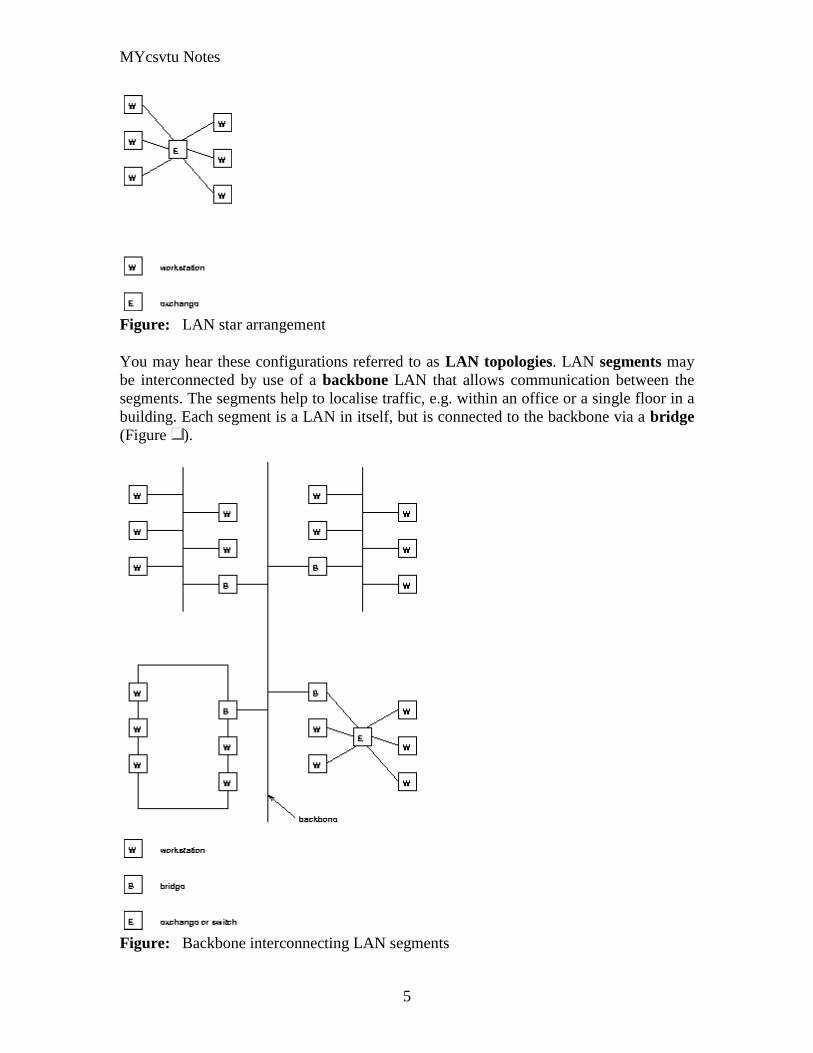
MYcsvtu Notes
5
Figure LAN star arrangement
You may hear these configurations referred to as LAN topologies LAN segments may
be interconnected by use of a backbone LAN that allows communication between the
segments The segments help to localise traffic eg within an office or a single floor in a
building Each segment is a LAN in itself but is connected to the backbone via a bridge
(Figure )
Figure Backbone interconnecting LAN segments
MYcsvtu Notes
6
WANs often exploit public networks such as the public telephone system (Figure )
There are two types of public network
Public switched telephone network (PSTN) This is the ordinary telephone
system This system exists in all countries of the world It was designed
specifically for the transmission of voice communication Digital systems
employing this network must produce a voice-like signal and accept the low
transmission rates
Public switched data network (PSDN) This is a public network designed
specifically for the transmission of digital data They arose from privately owned
WANs that required higher performance than the PSTN Many countries of the
world are introducing PSDN services They can support much higher transmission
rates An integrated services digital network (ISDN) is the term given to all-
digital networks that can carry simultaneously voice and data communication and
offer additionally a variety of teletex services ISDN services are being introduced
all round the world and are indeed on offer in the UK
Figure WANs to interconnect LANs
MANs are now taking some of the roles that WANs once had in particular environments
for LAN LAN interconnection due to the high speeds that they offer compared to most
MYcsvtu Notes
7
PSTNs and PSDNs eg FDDI and DQDB offer 100Mbs whereas a PSTN line may
offer say 192Kbs with a fast modem
At the present time the worlds communication systems are in a state of flux Historically
digital computing equipment conformed to the requirements of the PSTN Now
increasingly analogue traffic such as voice and video is conforming to the requirements
of the PSDN
Public networks employ two types of switching Switching describes the method by
which the corresponders are connected A circuit switched network (CSN) establishes a
connection through the network that is then used exclusively by the two correspondents
(Of course only in 19th century telephone exchanges is the switching actually current
driven) The PSTN is a circuit switched network A packet switched network (PSN)
divides the message into packets that are addressed to the recipient The packets are then
forwarded through the network together with many other packets These are locally
distributed on arrival The Post Office is a packet switched network More relevantly
LAN communication is exclusively via a PSN The outstanding advantage of the PSN is
that the two correspondents can communicate at different rates permitting much more
efficient use of the communication channel
The Communications Channel
A communication channel can be simplex in which only one party can transmit full-
duplex in which both correspondents can transmit and receive simultaneously or half-
duplex in which the correspondents alternate between transmitting and receiving states
(such as conversing adults) Even though the channel might be capable of supporting full-
duplex communication if the corresponding entities are not capable of transmitting and
receiving simultaneously the communications system will be half-duplex (as in the
example of the conversing adults)
Communication between two entities can be considered either in-band or out-of-band
depending on context In-band communication is communication which occurs via the
primary channel between the communicating entities Out-of-band communication occurs
via an alternative channel which is not considered to be the primary channel between the
entities
Which channel is primary and which is an alternate depends on context and the existence
of an alternative channel In the case of a conversation between two people the primary
channel could consist of verbal communication while the alternate channel consists of
visual body language Of course if emotions rise these two channels might reverse roles
with body language becoming the primary channel
MYcsvtu Notes
8
Simplex communication
From Wikipedia the free encyclopedia
Jump to navigation search
Simplex communication is a name for a type of communication circuit There are two
(contradictory) definitions that have been used for the term In both cases the other
definition is referred to as half duplex
Contents
[hide]
1 One way at a time
2 One way only
o 21 Examples according to ANSI definition
3 References
4 See also
One way at a time
According to the ITU-T definition a simplex circuit is one where all signals can flow in
only one direction at a time This was also the way Western Union used the term when
describing the duplex and simplex capacity of their new transatlantic telegraph cable
completed between Newfoundland and the Azores in 1928[1]
The same definition for a
simplex radio channel was used by the National Fire Protection Association in 2002[2]
One way only
According to the ANSI definition a simplex circuit is one where all signals can flow in
only one direction These systems are often employed in broadcast networks where the
receivers do not need to send any data back to the transmitterbroadcaster
To put it simply you wont find your radio receiver actually sending out any information
all it does is receive so information moves one way only from the radio broadcasting
station to your radio receiver
Half-Duplex
MYcsvtu Notes
9
A simple illustration of a half-duplex communication system
A half-duplex system provides for communication in both directions but only one
direction at a time (not simultaneously) Typically once a party begins receiving a signal
it must wait for the transmitter to stop transmitting before replying
An example of a half-duplex system is a two-party system such as a walkie-talkie style
two-way radio wherein one must use Over or another previously designated command
to indicate the end of transmission and ensure that only one party transmits at a time
because both parties transmit on the same frequency A good analogy for a half-duplex
system would be a one lane road with traffic controllers at each end Traffic can flow in
both directions but only one direction at a time with this being regulated by the traffic
controllers
Note that this is one of two contradictory definitions for half-duplex This
definition matches the ANSI standard For more detail see Simplex
communication
Full-Duplex
A simple illustration of a full-duplex communication system
A full-duplex system allows communication in both directions and unlike half-duplex
allows this to happen simultaneously Land-line telephone networks are full-duplex since
they allow both callers to speak and be heard at the same time A good analogy for a full-
duplex system would be a two lane road with one lane for each direction
Examples Telephone Mobile Phone etc
MYcsvtu Notes
10
Two way radios can be for instance designed as full-duplex systems which transmit on
one frequency and receive on a different frequency This is also called frequency-division
duplex Frequency-division-duplex systems can be extended to farther distances using
pairs of simple repeater stations owing to the fact the communications transmitted on any
one frequency always travels in the same direction
Full-duplex Ethernet connections work by making simultaneous use of all four physical
pair of twisted cable (which are inside the insulation) where two pair are used for
receiving packets and two pair are using for sending packets to a directly connected
device This effectively makes the cable itself a collision-free environment and
theoretically doubles the maximum bandwidth that can be supported by the connection
Channel Characteristics
A communications channel may be described in terms of its characteristic properties
These channel characteristics includebandwidth (how much information can be
conveyed across the channel in a unit of time commonly expressed in bits per second or
bps7 ) quality (how reliably can the information be correctly conveyed across the
channel commonly in terms of bit error rate or BER8 ) and whether the channel is
dedicated (to a single source) or shared (by multiple sources)
Obviously a higher bandwidth is usually a good thing in a channel because it allows more
information to be conveyed per unit of time High bandwidths mean that more users can
share the channel depending on their means of accessing it High bandwidths also allow
more demanding applications (such as graphics) to be supported for each user of the
channel
The capability of a channel to be shared depends of course on the medium used A shared
channel could be likened to a school classroom where multiple students might attempt to
simultaneously catch the teachers attention by raising their hand the teacher must then
arbitrate between these conflicting requests allowing only one student to speak at a time
Reliability of communication is obviously important A low quality channel is prone to
distorting the messages it conveys a high quality channel preserves the integrity of the
messages it conveys Depending on the quality of the channel in use between
communicating entities the probability of the destination correctly receiving the message
from the source might be either very high or very low If the message is received
incorrectly it needs to be retransmitted
If the probability of receiving a message correctly across a channel is too low the system
(source channel message destination) must include mechanisms which overcome the
errors introduced by the low quality channel Otherwise no useful communication is
possible over that channel These mechanisms are embodied in the communication
protocols employed by the corresponding entities
MYcsvtu Notes
11
The effective bandwidth describes what an application experiences and depends on the
quality of service (QOS) provided by the channel For example modems scale back their
transmission speed based largely on their perception of channel quality in order to
optimally use the transmission medium
In general shared and reliable channels are more resource efficient than those which
enjoy neither of these characteristics Shared channels enjoy greater efficiency than
dedicated ones because most data communication is bursty in nature with long idle
periods punctuated by brief message transmissions Reliable channels are more efficient
than unreliable ones because retransmissions are not required as often (because there are
fewer transmission-induced errors)
The OSI Reference Model
The Open Systems Interconnect (OSI) reference model is commonly used to describe in
an abstract manner the functions involved in data communication This model originally
conceived in the International Organization for Standardization (ISO) defines data
communications functions in terms of layers
In the OSI reference model each layer is responsible for certain basic functions such as
getting data from one device to another or from one application on a computer to another
The functions at each layer both depend and build on the functions-called services-
provided by the layers below it Communication between peer entities at a given layer is
done via one or more protocols this communication is invoked via the interface with the
layer below
The OSI reference model is depicted in Table 01 Successful communication between
two applications depends on successful functions at all seven layers In terms of
implementation it is possible for some layers to be trivial in the end what is required
depends on the needs of the applications (and people) engaged in communication
Table 01 OSI Reference Model
Layer Title
7 Application
Higher Layers 6 Presentation
5 Session
4 Transport
MYcsvtu Notes
12
3 Network
Lower Layers 2 Data Link
1 Physical
We must emphasize that the definition of a layered data communication architecture is
only an abstraction The intent of this definition is to unambiguously describe the
functions involved in data communication in a way which allows different systems to be
compared The OSI reference model definition is intended to neither imply nor constrain
the implementation of any communication system
Although various companies and standards bodies have created different layered
communications models the OSI reference model remains the universally-accepted
common denominator for abstract definition Other models define the layer functions
somewhat differently and often have fewer than seven layers In some cases constituent
protocols were specified before the abstract models defining the end-to-end
communication
We will now review the functions of the OSI layers and some of the primary protocols at
each layer9
Layer 1 - The Physical Layer
The physical layer functions include all physical aspects of communicating between two
directly-connected physical entities Typically these physical properties include
electromechanical characteristics of the medium or link between the communicating
physical entities such as connectors voltages transmission frequencies etc This layer
summarizes the physics which underlie the communication path
The essential service provided by the physical layer consists of an unstructured bit
stream which can be used by higher layers to provide the basis for higher layer
communication services An example of a physical layer is the ink on paper used by this
book to convey information Another example is the radio frequencies used in a wireless
communications system
Layer 2 - The Data Link Layer
The data link layer accepts the unstructured bit stream provided by the physical layer and
provides reliable transfer of data between two directly-connected Layer 2 entities
Directly-connected means that the Layer 2 entities communication path does not
require another Layer 2 entity However this does not imply a dedicated path in the case
MYcsvtu Notes
13
of Ethernet many Layer 2 entities can be sharing a common (physical) medium such as a
coaxial cable or a 10BASE-T hub
Layer 2 functionality is limited in scope-delivery of messages over a local area It could
be likened to an intra-office correspondence between co-workers there is a need for
reliability but addressing is relatively simple Local area networks (LANs) operate at
Layer 2
The data link layer is itself conceptually subdivided into two sublayers-medium access
control and logical link control-which more specifically define the primary aspects of
data link layer functionality However this conceptual partitioning by the IEEE 802
committee is somewhat arbitrary and subject to debate
The MAC Sublayer
The medium access control (MAC) sublayer is closely associated with the physical layer
and defines the means by which the physical channel (medium) may be accessed It
coordinates the attempts to seize a shared channel by multiple MAC entities much as a
school teacher must arbitrate between pupils conflicting desires to speak The MAC layer
commonly provides a limited form of error control especially for any header information
which defines the MAC-level destination and higher-layer access mechanism
Ethernet (IEEE 8023) is a prime example of a shared medium with a defined MAC
sublayer functionality The shared medium in Ethernet has traditionally consisted of a
coaxial cable into which multiple entities were tapped as depicted in Figure 05
Although this topology still applies conceptually a hub and spoke medium is now
typically used in which the earlier coaxial cable has been physically collapsed into a hub
device
Figure 05 Ethernet MAC System
11
As a contention medium Ethernet defines how devices sense a channel for its
availability wait when it is busy seize the channel when it becomes available and back-
off for a random length of time following a collision with another simultaneously
MYcsvtu Notes
14
transmitting device On a shared channel such as Ethernet only a single entity can
transmit at a time or messages will be garbled
Not all shared channels involve contention A prime example of a contentionless shared
medium is token ring (IEEE 8025) in which control of the channel is rotated between
the devices sharing the channel in a deterministic round-robin manner Conceptually
control of the channel is given to the entity currently possessing a token If the device
has nothing to transmit it passes the token to the next device attached to the topological
ring depicted in Figure 06
Figure 06 Token Ring MAC System
11
IEEE-defined MAC sublayer addresses are six bytes long and permanently assigned to
each device typically called a network interface card orNIC The IEEE administers the
assignment of these addresses in blocks to manufacturers to assure the global uniqueness
that the MAC sublayer protocols rely on for plug Ocircn play network setup Each
manufacturer must assure individual device identifier uniqueness within their assigned
block
The LLC Sublayer
The logical link control (LLC) sublayer is responsible for reliable transfer of messages-
called frames or more formally link protocol data units (LPDUs)-between two directly-
connected Layer 2 entities Functions needed to support this reliable transfer include
framing (indicating where a Layer 2 message begins and ends) sequence control error
control and flow control
MYcsvtu Notes
15
The degree to which sequence error and flow control are provided by the LLC sublayer
is determined by whether the link protocol is connection-oriented or connectionless A
connectionless link protocol provides little if any support for these functions A
connection-oriented link might use a windowing technique for these functions in which
frames are individually numbered and acknowledged by their sequence number with
only a few such frames outstanding at any time
The connection-oriented functions of sequencing error and flow control provide a
foundation for services provided by higher layers As mentioned earlier not all layer or
sublayer functions are explicitly designed or implemented in any given system Provision
of these functions depends on the services required by higher layers
If the connection-oriented functions of the LLC sublayer are not implemented they must
be performed by higher layers for reliable end-to-end communication If these functions
are provided by several layers they might be somewhat redundant and add unnecessary
overhead (inefficiency) to the system In the worst case redundant provision of these
functions at multiple layers could serve cross purposes and actually degrade overall
system performance
An example of a connectionless LLC protocol is frame relay (T1617 618) which
defines point-to-point links with switches connecting individual links in a mesh topology
In a frame relay network endpoints are connected by a series of links and switches
Because frame relay is defined in terms of the links between frame relay access devices
(FRADs) and switches and between switches themselves it is an LLC protocol
Connectionless Layer 2 protocols are best suited for high quality transmission media
With high quality transmission media errors are rarely introduced in the transmission
between network layer entities and discovery of and recovery from errors is most
efficiently handled by the communicating hosts In this case it is better to move the
packets quickly across the traversed subnetworks from source to destination rather than
checking for errors at Layer 2
Frame relay is derived from the X25 (ISO 8208) protocol which spans Layers 2 and 3
X25 is a connection-oriented packet-switching technology which defines how
neighboring packet switches exchange data with one another in a reliable manner from
end-to-end Frame relay simply removes the connection-oriented functions of error and
sequence control however congestion control functions are provided in frame relay to
prevent the total traffic seen at any point in the network from overwhelming it
Connection-oriented Layer 2 protocols are best suited for low quality transmission media
where it is more efficient and cost-effective to discover and recover from errors as they
occur on each hop than to rely on the communicating hosts to perform error recovery
functions With ever-increasing quality of transmission facilities and decreasing costs of
computation capability at hosts the need for connection-oriented network layer protocols
is diminishing However X25 remains popular outside of North America where it has
been tariffed at levels which encourage its use
MYcsvtu Notes
16
End-to-end communications may be via shared or dedicated facilities or circuits Shared
facilities involve the use of packet switching technology to carry messages from end-to-
end messages are subdivided as necessary into packets which share physical and logical
channels with packets from various sources to various destinations Packet switching is
almost universally used in data communications because it is more efficient for the bursty
nature of data traffic
On the other hand some applications require dedicated facilities from end-to-end because
they are isochronous (eg voice) or bandwidth-intensive (eg large file transfer) This
mode of end-to-end circuit dedication is called circuit switched communication Because
the facilities are dedicated to a single user this tends to be much more expensive than the
packet switched mode of communication But some applications need it-it is an economic
trade-off
Dedicated circuits are a rather extreme form of connection-oriented protocol requiring
the same setup and tear-down phases prior to and following communication If the circuit
setup and tear-down is statically arranged (ie out-of-band) it is referred to as a
permanent virtual circuit or PVC If the circuit is dynamically setup and torn-down in-
band it is referred to as a switched virtual circuit or SVC
Layer 3 - The Network Layer
The network layer defines the functions necessary to support data communication
between indirectly-connected entities It provides the capability of forwarding messages
from one Layer 3 entity to another until the final destination is reached
The network layer introduces another layer of abstraction to the data communications
model It moves messages-called packets or more formally network protocol data units
(NPDUs)-between communicating Layer 3 entities-called end systems nodes or hosts
Network layer functions include route determination or routing and forwarding of
packets to their final destinations
In order to forward a packet to its destination host routing information must be provided
to theintermediate systems (ISs) or routers responsible for forwarding packets to their
respective destinations This routing information includes the address of the destination
which is contained in each packet The next hop to be traversed by the packet is
determined primarily by this destination address We will talk more about addressing and
routing in Chapter 1
This packet forwarding and routing is accomplished independent of both the media and
transmission types used at any step along the way The unimportance of local topology to
the network layer is demonstrated by the common use of cloud diagrams to depict
networks as in Figure 07 Since the network layer is concerned with getting packets
across many local networks called subnetworks its title would be more accurate if it
were the Internetwork Layer
MYcsvtu Notes
17
Figure 07 Network Layer ``Cloud
Diagram
11
The network layer functionality is global in scope-delivery of messages over a wide area
It could be likened to the postal system in which correspondence is passed from location
to location until it eventually reaches the destination address on the envelope10
The
network layer is the domain of wide area networks (WANs)
In order for routers to know how (ie on which link) to forward packets they must have
some knowledge of network topology This knowledge may be complete or partial and is
dynamically created and maintained via routing protocols used by routers to share their
knowledge of network topology with each other Routing is essentially the reduction of
global internetwork topology to local hop-by-hop routing decisions made
independently by each router
As with Layer 2 Layer 3 protocols may be connection-oriented or connectionless A
connection-oriented Layer 3 protocol such as X25 (ISO 8208) operates more statically
The basic idea is that an end-to-end route (X25 virtual connection) is established from
the originating data terminal equipment (DTE) to data communications equipment
(DCE) from DCE to DCE through the network then from the last DCE to the
terminating DTE this is the call setup Packets are then transmitted via this prearranged
route with all packets following the same path through the network Finally the route is
torn down (release) and packets cease flowing
X25 operation is like a phone call because it is a phone call X25 Layer 3 operation
assumes that a reliable connection-oriented service is provided by Layer 2 (also defined
by the X25 standard) although it does provide flow control via sequence numbers
Connectionless Layer 3 protocols such as the ever popular internet protocol (IP)(RFC11
791 and 792) and its ISO counterpart connectionless network protocol (CLNP) (ISO
MYcsvtu Notes
18
8473) route packets dynamically There is no prearranged path which is followed by
subsequent packets flowing from one host to another Instead each packet is individually
routed through a routing mesh there is no reason to believe that sequential packets
flowing between hosts will follow the same path So sequence errors may be introduced
at Layer 3 which must be corrected by a higher layer entity
Connectionless data packets are commonly referred to as datagrams and the service
provided by connectionless Layer 3 protocols is referred to as datagram service Stateless
datagram service is simpler for Layer 3 entities than connection-oriented network layer
services Because there is no state information to maintain dynamic routing protocols can
be used If a router fails during the dialogue between two communicating hosts
neighboring routers will discover this via the routing protocols and find alternate routes
which bypass the failed router
There seems to be a fair amount of ambiguity between the network layer and the LLC
sublayer Both can provide connection-oriented or connectionless services to higher
layers To a large extent if Layer 3 is explicitly implemented there is no need for an
LLC sublayer The primary difference is in scope-LLC addresses and protocols are
oriented toward a more local environment whereas network layer addresses and protocols
are global in scope
Excellent references to routing and forwarding of data packets can be found in [PERL92]
and [STEN95]
Layer 4 - The Transport Layer
The transport layer is concerned with getting Layer 4 messages-called segments or more
formally transport protocol data units (TPDUs) -from source to destination in a reliable
manner The perspective of Layer 4 is of end-to-end communications rather than the hop-
by-hop perspective of Layer 3 Layer 4 assumes that packets can be moved from network
entity to network entity eventually getting to the final destination host How this is
accomplished is of no concern to Layer 4 functionality
Like other layers transport layer protocols can be either connection-oriented or
connectionless depending on the services required by higher layers A common
implementation of Layers 3 and 4 involves a connection-oriented transport layer protocol
running over a connectionless network layer protocol such as the ubiquitous TCPIP
protocol suite In this instance the communicating hosts maintain state information on
communications with each other to determine when and what to send This state
information defines the connection between the communicating Layer 4 entities
The general idea here is that two communicating hosts need not be concerned with the
topology of the internetwork which lies between them They only need to know the state
of their pairwise communication If part of the intervening internetwork cloud suffers a
failure the Layer 3 entities (routers) will deal with it and recover dynamically Aside
MYcsvtu Notes
19
from potential retransmission of any lost segments the hosts Layer 4 entries do not have
to be at all concerned with routing and recovery activities at Layer 3
In the IP protocol suite the primary connectionless Layer 4 protocol is the User
Datagram Protocol (UDP)(RFC 768) which is carried by IP the primary connection-
oriented protocol is the Transmission Control Protocol (TCP)(RFC 793) The ISO world
defines five classes of transport layer protocol beginning with Class 0 (TP-0) for
connectionless operation and range up to Class 4 (TP-4)(ISO 8073) for connection-
oriented operation
Layer 5 - The Session Layer
The session layer provides a control structure for communication between applications
on hosts The communication at layer 5 is called a session which defines the relative
timing of communications between the hosts applications Synchronization of
communicating applications comes into play when coordinated timing of corresponding
events at the endpoints is imperative such as in financial transactions
Remember layers define communication functions not implementations It is unlikely
that a session layer would be explicitly implemented as a stand-alone program although
its functions would be implemented somewhere Session layer functions depend on the
reliability of communications between the endpoints and session layer functions must
therefore be implemented above Layer 4
Layer 6 - The Presentation Layer
The presentation layer performs any necessary data transformations or formatting
required by the end applications Functions provided by the presentation layer include
data compression file formatting and encryption Common data formatting is important
because it allows the same application file to be accessed by the application running on
different computer platforms This book is itself the product of an application running on
different platforms with common files being modified via these different platforms
Abstract Syntax Notation (ASN1) is commonly used to specify data values in a way
which allows processors to communicate independent of their varying native integer
sizes bit orderings (big or little endian) character sets etc ASN1 is a transfer syntax a
presentation layer formatting which appears frequently in the CDPD specification for
unambiguous definition of network management accounting limited size messaging and
other functions
An example of ASN1 encoding from an accounting Traffic Matrix Segment in the
CDPD specification is the following
MYcsvtu Notes
20
TrafficType = INTEGER
registration (0)
deregistration (1)
ip(2)
clnp(3)
Layer 7 - The Application Layer
The application layer provides the services which directly support an application running
on a host These services are directly accessible by an application via common well-
known application program interfaces (APIs) which can actually occur at many layers
Examples of layer 7 services include FTP (file transfer protocol) Telnet and SNMP
(simple network management protocol) Most network management activities are based
on the services provided by layer 7 application entities which in turn rely on lower layer
services to be able to perform their functions
7 Application ECHO ENRP FTP Gopher HTTP NFS RTSP SIP SMTP SNMP
SSH Telnet Whois XMPP
6 Presentation XDR ASN1 SMB AFP NCP
5 Session ASAP TLS SSL ISO 8327 CCITT X225 RPC NetBIOS ASP
4 Transport TCP UDP RTP SCTP SPX ATP IL
3 Network IP ICMP IGMP IPX OSPF RIP IGRP EIGRP ARP RARP X25
2 Data Link Ethernet Token ring HDLC Frame relay ISDN ATM 80211 WiFi
FDDI PPP
1 Physical 10BASE-T 100BASE-T 1000BASE-T SONETSDH G709 T-
carrierE-carrier various 80211 physical layers
The TCPIP Reference Model
The TCPIP reference model is the network model used in the current Internet
architecture [19] It has its origins back in the 1960s with the grandfather of the Internet
the ARPANET This was a research network sponsored by the Department of Defense in
the United States The following were seen as major design goals
ability to connect multiple networks together seamlessly
ability for connections to remain intact as long as the source and destination
machines were functioning
MYcsvtu Notes
21
to be built on flexible architecture
The reference model was named after two of its main protocols TCP (Transmission
Control Protocol) [12] and IP (Internet Protocol)
They choose to build a packet-switched network based on a connectionless internetwork
layer
Figure 21 TCPIP Network Protocol
A detailed description of the reference model is beyond the scope of this document and
project The basic idea of the networking system is to allow one application on a host
computer to talk to another application on a different host computer
The application forms its request then passes the packet down to the lower layers which
add their own control information either a header or a footer onto the packet Finally the
packet reaches the physical layer and is transmitted through the cable onto the destination
host The packet then travels up through the different layers with each layer reading
deciphering and removing the header or footer that was attached by its counterpart on the
originating computer Finally the packet arrives at the application it was destined for
Even though technically each layer communicates with the layer above or below it the
process can be viewed as one layer talking to its partner on the host as figure 21 shows
The Host-to-Network Layer
The Host-to-Network layer interfaces the TCPIP protocol stack to the physical network
The TCPIP reference model does not specify in any great detail the operation of this
layer except that the host has to connect to the network using some protocol so it can
send IP packets over it
As it is not officially defined it varies from implementation to implementation with
vendors supplying their own version
MYcsvtu Notes
22
The Network Layer
The job of the network layer is to inject packets into any network and have them travel
independently to the destination The layer defines IP (Internet Protocol) for its official
packet format and protocol Packet routing is a major job of this protocol
The Transport Layer
The transport layer is the interface between the application layer and the complex
hardware of the network It is designed to allow peer entities on the source and
destination hosts to carry on conversations
Data may be user data or control data Two modes are available full-duplex and half
duplex In full-duplex operation both sides can transmit and receive data simultaneously
whereas in half duplex a side can only send or receive at one time
Interaction between the transport layer and the layers immediately above and below are
shown in figure 22 Any program running in the application layer has the ability to send
a message using TCP or UDP which are the two protocols defined for the transport layer
The application can communicate with the TCP or the UDP service whichever it
requires Both the TCP and UDP communicate with the Internet Protocol in the internet
layer In all cases communication is a two way process The applications can read and
write to the transport layer The diagram only shows two protocols in the transport layer
TTCP will also reside in this layer between the other two protocols and function in the
same manner
Figure 22 Interaction with Application Transport and Internet Layers
A message to be sent originates in the application layer This is then passed down onto
the appropriate protocol in the transport layer These protocols add a header to the
message for the corresponding transport layer in the destination machine for purposes of
reassembling the message The segment is then passed onto the internet layer where the
Internet Protocol adds a further header Finally the segment is passed onto the physical
MYcsvtu Notes
23
layer a header and a trailer are added at this stage Figure 23 shows the structure of the
final segment being sent
Figure 23 Transmitted Segment from TCPIP Network
The Application Layer
The original TCPIP specification described a number of different applications that fit
into the top layer of the protocol stack These applications include Telnet FTP SMTP
and DNS
Telnet is a program that supports the TELNET [13] protocol over TCP TELNET is a
general two-way communication protocol that can be used to connect to another host and
run applications on that host remotely
FTP (File Transfer Protocol) [14] is a protocol that was originally designed to promote
the sharing of files among computer users It shields the user from the variations of file
storage on different architectures and allows for a reliable and efficient transfer of data
SMTP (Simple Mail Transport Protocol) [15] is the protocol used to transport electronic
mail from one computer to another through a series of other computers along the route
DNS [10] (Domain Name System) resolves the numerical address of a network node into
its textual name or vice-versa It would translate wwwyahoocom to 2047117771 to
allow the routing protocols to find the host that the packet is destined for
What is a Topology
The physical topology of a network refers to the configuration of cables computers and
other peripherals Physical topology should not be confused with logical topology which
is the method used to pass information between workstations Logical topology was
discussed in the Protocol chapter
Main Types of Physical Topologies
The following sections discuss the physical topologies used in networks and other related
topics
Linear Bus
MYcsvtu Notes
24
Star
Star-Wired Ring
Tree
Considerations When Choosing a Topology
Summary Chart
Linear Bus
A linear bus topology consists of a main run of cable with a terminator at each end (See
fig 1) All nodes (file server workstations and peripherals) are connected to the linear
cable Ethernet and LocalTalk networks use a linear bus topology
Fig 1 Linear Bus topology
Advantages of a Linear Bus Topology
Easy to connect a computer or peripheral to a linear bus
Requires less cable length than a star topology
Disadvantages of a Linear Bus Topology
Entire network shuts down if there is a break in the main cable
Terminators are required at both ends of the backbone cable
Difficult to identify the problem if the entire network shuts down
Not meant to be used as a stand-alone solution in a large building
Star
A star topology is designed with each node (file server workstations and peripherals)
connected directly to a central network hub or concentrator (See fig 2)
Data on a star network passes through the hub or concentrator before continuing to its
destination The hub or concentrator manages and controls all functions of the network It
also acts as a repeater for the data flow This configuration is common with twisted pair
cable however it can also be used with coaxial cable or fiber optic cable
MYcsvtu Notes
25
Fig 2 Star topology
Advantages of a Star Topology
Easy to install and wire
No disruptions to the network then connecting or removing devices
Easy to detect faults and to remove parts
Disadvantages of a Star Topology
Requires more cable length than a linear topology
If the hub or concentrator fails nodes attached are disabled
More expensive than linear bus topologies because of the cost of the
concentrators
The protocols used with star configurations are usually Ethernet or LocalTalk Token
Ring uses a similar topology called the star-wired ring
Star-Wired Ring
A star-wired ring topology may appear (externally) to be the same as a star topology
Internally the MAU (multistation access unit) of a star-wired ring contains wiring that
allows information to pass from one device to another in a circle or ring (See fig 3) The
Token Ring protocol uses a star-wired ring topology
Tree
A tree topology combines characteristics of linear bus and star topologies It consists of
groups of star-configured workstations connected to a linear bus backbone cable (See fig
MYcsvtu Notes
26
4) Tree topologies allow for the expansion of an existing network and enable schools to
configure a network to meet their needs
Fig 4 Tree topology
Advantages of a Tree Topology
Point-to-point wiring for individual segments
Supported by several hardware and software venders
Disadvantages of a Tree Topology
Overall length of each segment is limited by the type of cabling used
If the backbone line breaks the entire segment goes down
More difficult to configure and wire than other topologies
5-4-3 Rule
A consideration in setting up a tree topology using Ethernet protocol is the 5-4-3 rule
One aspect of the Ethernet protocol requires that a signal sent out on the network cable
reach every part of the network within a specified length of time Each concentrator or
repeater that a signal goes through adds a small amount of time This leads to the rule that
between any two nodes on the network there can only be a maximum of 5 segments
connected through 4 repeatersconcentrators In addition only 3 of the segments may be
populated (trunk) segments if they are made of coaxial cable A populated segment is one
which has one or more nodes attached to it In Figure 4 the 5-4-3 rule is adhered to The
MYcsvtu Notes
27
furthest two nodes on the network have 4 segments and 3 repeatersconcentrators
between them
This rule does not apply to other network protocols or Ethernet networks where all fiber
optic cabling or a combination of a fiber backbone with UTP cabling is used If there is a
combination of fiber optic backbone and UTP cabling the rule is simply translated to 7-
6-5 rule
] Mesh
Full
Fully Connected The type of network topology in which each of the nodes of the network is
connected to each of the other nodes in the network with a point-to-point link ndash
this makes it possible for data to be simultaneously transmitted from any single
node to all of the other nodes
Note The physical fully connected mesh topology is generally too costly and
complex for practical networks although the topology is used when there are only
a small number of nodes to be interconnected[3]
Partial
Partially Connected The type of network topology in which some of the nodes of the network are
connected to more than one other node in the network with a point-to-point link ndash
this makes it possible to take advantage of some of the redundancy that is
provided by a physical fully connected mesh topology without the expense and
complexity required for a connection between every node in the network
Note In most practical networks that are based upon the physical partially
connected mesh topology all of the data that is transmitted between nodes in the
network takes the shortest path between nodes except in the case of a failure or
break in one of the links in which case the data takes an alternate path to the
destination ndash this implies that the nodes of the network possess some type of
logical routing algorithm to determine the correct path to use at any particular
time
[edit] Hybrid Network Topologies
The hybrid topology is a type of network topology that is composed of one or more
interconnections of two or more networks that are based upon different physical
topologies or a type of network topology that is composed of one or more
interconnections of two or more networks that are based upon the same physical
topology but where the physical topology of the network resulting from such an
interconnection does not meet the definition of the original physical topology of the
interconnected networks (eg the physical topology of a network that would result from
an interconnection of two or more networks that are based upon the physical star
topology might create a hybrid topology which resembles a mixture of the physical star
MYcsvtu Notes
28
and physical bus topologies or a mixture of the physical star and the physical tree
topologies depending upon how the individual networks are interconnected while the
physical topology of a network that would result from an interconnection of two or more
networks that are based upon the physical distributed bus network retains the topology of
a physical distributed bus network)
Star-Bus A type of network topology in which the central nodes of one or more individual
networks that are based upon the physical star topology are connected together
using a common bus network whose physical topology is based upon the
physical linear bus topology the endpoints of the common bus being terminated
with the characteristic impedance of the transmission medium where required ndash
eg two or more hubs connected to a common backbone with drop cables
through the port on the hub that is provided for that purpose (eg a properly
configured uplink port) would comprise the physical bus portion of the physical
star-bus topology while each of the individual hubs combined with the
individual nodes which are connected to them would comprise the physical star
portion of the physical star-bus topology
Star-of-Stars
Hierarchical Star A type of network topology that is composed of an interconnection of individual
networks that are based upon the physical star topology connected together in a
hierarchical fashion to form a more complex network ndash eg a top level central
node which is the hub of the top level physical star topology and to which other
second level central nodes are attached as the spoke nodes each of which in
turn may also become the central nodes of a third level physical star topology
Notes 1) The physical hierarchical star topology is not a combination of the physical
linear bus and the physical star topologies as cited in some texts as there is no
common linear bus within the topology although the top level hub which is the
beginning of the physical hierarchical star topology may be connected to the
backbone of another network such as a common carrier which is topologically
not considered to be a part of the local network ndash if the top level central node is
connected to a backbone that is considered to be a part of the local network then
the resulting network topology would be considered to be a hybrid topology that
is a mixture of the topology of the backbone network and the physical hierarchical
star topology
2) The physical hierarchical star topology is also sometimes incorrectly referred
to as a physical tree topology since its physical topology is hierarchical however
the physical hierarchical star topology does not have a structure that is determined
by a branching factor as is the case with the physical tree topology and therefore
nodes may be added to or removed from any node that is the hub of one of the
individual physical star topology networks within a network that is based upon the
physical hierarchical star topology
3) The physical hierarchical star topology is commonly used in outside plant
(OSP) cabling to connect various buildings to a central connection facility which
MYcsvtu Notes
29
may also house the demarcation point for the connection to the data transmission
facilities of a common carrier and in inside plant (ISP) cabling to connect
multiple wiring closets within a building to a common wiring closet within the
same building which is also generally where the main backbone or trunk that
connects to a larger network if any enters the building
Star-wired Ring A type of hybrid physical network topology that is a combination of the physical
star topology and the physical ring topology the physical star portion of the
topology consisting of a network in which each of the nodes of which the network
is composed are connected to a central node with a point-to-point link in a hub
and spoke fashion the central node being the hub and the nodes that are
attached to the central node being the spokes (eg a collection of point-to-point
links from the peripheral nodes that converge at a central node) in a fashion that is
identical to the physical star topology while the physical ring portion of the
topology consists of circuitry within the central node which routes the signals on
the network to each of the connected nodes sequentially in a circular fashion
Note In an 8025 Token Ring network the central node is called a Multistation
Access Unit (MAU)
Hybrid Mesh A type of hybrid physical network topology that is a combination of the physical
partially connected topology and one or more other physical topologies the mesh
portion of the topology consisting of redundant or alternate connections between
some of the nodes in the network ndash the physical hybrid mesh topology is
commonly used in networks which require a high degree of availability
Considerations When Choosing a Topology
Money A linear bus network may be the least expensive way to install a network
you do not have to purchase concentrators
Length of cable needed The linear bus network uses shorter lengths of cable
Future growth With a star topology expanding a network is easily done by
adding another concentrator
Cable type The most common cable in schools is unshielded twisted pair which
is most often used with star topologies
Summary Chart
Common Cable Common Protocol
Linear Bus Twisted Pair
Coaxial
Ethernet
LocalTalk
MYcsvtu Notes
30
Fiber
Star Twisted Pair
Fiber
Ethernet
LocalTalk
Star-Wired Ring Twisted Pair Token Ring
Tree
Twisted Pair
Coaxial
Fiber
Ethernet
Internet vs Web
The Internet and the World Wide Web are not synonymous the Internet is a collection of
interconnected computer networks linked by copper wires fiber-optic cables wireless
connections etc the Web is a collection of interconnected documents and other
resources linked by hyperlinks and URLs The World Wide Web is accessible via the
Internet as are many other services including e-mail file sharing and others described
below
The best way to define and distinguish between these terms is to understand the Internet
protocol suite This collection of protocols is organized into layers such that each layer
provides the foundation and the services required by the layer above In this conception
the term Internet refers to computer networks that all communicate with IP (Internet
protocol) and TCP (transfer control protocol) Once this networking structure is
established then other protocols can run ―on top These other protocols are sometimes
called services or applications Hypertext transfer protocol or HTTP is an application
layer protocol that links billions of files together into the World Wide Web
Common uses of the Internet
The World Wide Web
Through keyword-driven Internet research using search engines like Google
millions worldwide have easy instant access to a vast and diverse amount of
online information Compared to encyclopedias and traditional libraries the
World Wide Web has enabled a sudden and extreme decentralization of
information and data
Many individuals and some companies and groups have adopted the use of Web logs or
blogs which are largely used as easily-updatable online diaries Some commercial
organizations encourage staff to fill them with advice on their areas of specialization in
the hope that visitors will be impressed by the expert knowledge and free information
and be attracted to the corporation as a result One example of this practice is Microsoft
MYcsvtu Notes
31
whose product developers publish their personal blogs in order to pique the publics
interest in their work
For more information on the distinction between the World Wide Web and the Internet
itself mdash as in everyday use the two are sometimes confused mdash see Dark internet where
this is discussed in more detail
Remote access
The Internet allows computer users to connect to other computers and information stores
easily wherever they may be across the world They may do this with or without the use
of security authentication and encryption technologies depending on the requirements
This is encouraging new ways of working from home collaboration and information
sharing in many industries An accountant sitting at home can audit the books of a
company based in another country on a server situated in a third country that is remotely
maintained by IT specialists in a fourth These accounts could have been created by
home-working book-keepers in other remote locations based on information e-mailed to
them from offices all over the world Some of these things were possible before the
widespread use of the Internet but the cost of private leased lines would have made
many of them infeasible in practice
An office worker away from his desk perhaps the other side of the world on a business
trip or a holiday can open a remote desktop session into his normal office PC using a
secure Virtual Private Network (VPN) connection via the Internet This gives him
complete access to all his normal files and data including e-mail and other applications
while he is away
This concept is also referred to by some network security people as the Virtual Private
Nightmare because it extends the secure perimeter of a corporate network into its
employees homes this has been the source of some notable security breaches but also
provides security for the workers
Functions
File-sharing
Instant messaging
Internet fax
Search engine
World Wide Web
MYcsvtu Notes
32
Intranets
What are Intranets
bull Intranet is Intra+ Net so an Intranet is an internal or private Internet used strictly
within the confines of a company university or organization Inter means
between or among hence the difference between the Internet and an Intranet
Some formal definitions of Intranets
bull Brown amp Duguid ―Intranets help present and
circulate boundary objects
bull Choo Detlor amp Turnbull ―Intranetshellip support the creation sharing and use of
knowledge
bull Stenmark ―Intranets are organizationally
restricted
A technical definition
bull An Intranet is a network based on the internet TCPIP open standard An intranet
belongs to an organization and is designed to be accessible only by the
organizations members employees or others with authorization An intranets
Web site looks and act just like other Web sites but has a firewall surrounding it
to fend off unauthorized users
Design Of Intranets
Steps
bull Analyze the organizationlsquos information ecology
bull Identify the typical problems experienced by users
bull Analyze the information behaviors of these set of users
bull Create value added processes to resolve the problems of users and to improve the
Information Ecology
Value Added Processes
bull Intranets may be designed to improve the organizational information ecology
MYcsvtu Notes
33
bull Intranets provide a unified information space in which users can communicate
and collaborate with others
bull intranet applications and services may add value by supporting the organizationlsquos
knowledge creating and decision making process
Two Models of Online Environments
Centralized
Distributed
Centralized Environments
bull Before the web the centralized model was all we had (examples include
CompuServe Prodigy)
bull On the web centralized models include site-based services such as Yahoo
bull Most (all) college and university services are offered using the centralized
model
MYcsvtu Notes
34
bull But centralized environments are static inflexible expensive
Distributed Environments
bull The World Wide Web is an example of a distributed environment
bull Resources access are not centralized but scattered around the world
ndash Resources in the form of a network of connected (via DNS) web servers
ndash Access in the form of a network of connected (via DNS) internet service
providers
ndash Users in the form of individualized and connected (via HTTP) web
browsers
bull The big issue ndash integration ndash that is making different systems work together
Design Principles
Network Design Principles
ndash Specifies how networks differ from traditional learning
ndash The idea is that each principle confers an advantage over non-network
systems
ndash Can be used as a means of evaluating new technology
1 Decentralize
ndash Centralized networks have a characteristic starlsquo shape
bull Some entities have many connections
bull The vast majority have few
bull Eg broadcast network teacher in a classroom
ndash Decentralized networks form a mesh
bull The weight of connections flow is distributed
bull Balanced load = more stable
bull Foster connections between entities fill outlsquo the star
Distribute
ndash Network entities reside in different physical locations
bull Reduces risk of network failure
bull Reduces need for major infrastructure such as powerful servers
large bandwidth massive storage
ndash Examples
bull Peer-to-peer networks such as Kazaa Gnutella
bull Content syndication networks such as RSS
ndash Emphasis is on sharing not copying
bull Locallsquo copies are temporary
MYcsvtu Notes
35
Computer Graphics
Computer Graphics is about animation (films)
Games are very important in Computer Graphics
Medical Imaging is another driving force
Computer Aided Design too
Graphics Definitions
bull Point
ndash a location in space 2D or 3D
ndash sometimes denotes one pixel
bull Line
ndash straight path connecting two points
ndash infinitesimal width consistent density
ndash beginning and end on points
bull Vertex
ndash point in 3D
bull Edge
ndash line in 3D connecting two vertices
bull PolygonFaceFacet
ndash arbitrary shape formed by connected vertices
ndash fundamental unit of 3D computer graphics
bull Raster
ndash derived from TV systems for a row of pixels
ndash commonly referred to as a scanline
ndash does influence algorithms ndash reducing memory requirements parallelism
etc
ndash is the derivation of rasterization scan-line algorithms
Displays
bull Most desktop displays use a cathode ray tube (CRT) while portable computing
devices such as laptops incorporate liquid crystal display (LCD)
bull Because of their slimmer design and smaller energy consumption monitors using
LCD technologies are beginning to replace the venerable CRT on many desktops
Cathode-Ray Tubes
MYcsvtu Notes
36
bull Classical output device is a monitor
bull Cathode-Ray Tube (CRT)
ndash Invented by Karl Ferdinand Braun (1897)
ndash Beam of electrons directed from cathode (-)to phosphor-coated
(fluorescent) screen (anode (+))
ndash Directed by magnetic focusing and deflection coils (anodes) in vacuum
filled tube
ndash Phosphor emits photon of light when hit by an electron of varied
persistence (long 15-20 ms for texts short lt 1ms for animation)
ndash Refresh rate (50-60 Hz 72-76 Hz) to avoid flicker trail
ndash Phosphors are organic compounds characterized by their persistence and
their color (blue red green)
Cathode-Ray Tubes
bull Cathode-Ray Tube (CRT)
ndash Horizontal deflection and vertical deflection direct the electron beam to
any point on the screen
ndash Intensity knob regulates the flow of electrons by controlling the voltage at
the control grid (high voltage reduces the electron density and thus
brightness)
ndash Accelerating voltage from positive coating inside screen (anode screen) or
an accelerating anode
bull Image maintenance
ndash Charge distribution to store picture information
OR
ndash Refresh CRT refreshes the display constantly to maintain phosphor glow
Cathode-Ray Tubes
bullCathode-Ray Tube (CRT)
ndash Horizontal deflection and vertical deflection direct the electron beam to any point
on the screen
ndash Intensity knob regulates the flow of electrons by controlling the voltage at the
control grid (high voltage reduces the electron density and thus brightness)
ndash Accelerating voltage from positive coating inside screen (anode screen) or an
accelerating anode
bullImage maintenance
ndash Charge distribution to store picture information
OR
ndash Refresh CRT refreshes the display constantly to maintain phosphor glow
bull Characteristics of Cathode-Ray Tube (CRT)
MYcsvtu Notes
37
ndash Intensity is proportional to the number of electrons repelled in beam per
second (brightness)
ndash Resolution is the maximum number of points that can be displayed
without overlap is expressed as number of horizontal points by number of
vertical points points are called pixels (picture elements) example
resolution 1024 x 768 pixels Typical resolution is 1280 x 1024 pixels
bull High-definition systems high resolution systems
bull Focusing
ndash Focusing forces the electron beam to converge to a point on the monitor
screen
ndash Can be electrostatic (lens) or magnetic (field)
bull Deflection
ndash Deflection directs the electron beam horizontally andor vertically to any
point on the screen
ndash Can be controlled by electric (deflection plates slide 9) or magnetic fields
(deflection coils slide 5)
ndash Magnetic coils two pairs (topbottom leftright) of tube neck
ndash Electric plates two pairs (horizontal vertical)
Raster-scan Displays
bullVideo displays can be either raster-scan or random-scan displays
bullRaster-scan display is the most common type of monitor using a CRT
bullThe electron beam scans the screen from top to bottom one row at a time Each row is
called a scan line
bullThe electron beam is turned on and off to produce a collection of dots painted one row at
a time These will form the image
bullA raster is a matrix of pixels covering the screen area and is composed of raster lines
Raster-scan Displays
MYcsvtu Notes
38
Raster-scan Displays
bullThe image is stored in a frame buffer containing the total screen area and where each
memory location corresponds to a pixel
bullIn a monochrome system each bit is 1 or 0 for the corresponding pixel to be on or off
(bitmap)
bullThe display processor scans the frame buffer to turn electron beam onoff depending if
the bit is 1 or 0
bullFor color monitors the frame buffer also contains the color of each pixel (color buffer)
as well as other characteristics of the image (gray scale hellip) 8 bitspixel 0255
(pixmap)
bullDepth of the buffer area is the number of bits per pixel (bit planes) up to 24
bullExamples television panels printers PC monitors (99 of raster-scan)
Raster-scan Displays
bullRefresh rate 24 is a minimum to avoid flicker corresponding to 24 Hz (1 Hz = 1 refresh
per second)
bullCurrent raster-scan displays have a refresh rate of at least 60 frames (60 Hz) per second
up to 120 (120 Hz)
bullUses large memory 640x480 307200 bits 38 kB
bullRefresh procedure
MYcsvtu Notes
39
ndashHorizontal retrace ndash beam returns to left of screen
ndashVertical retrace ndash bean returns to top left corner of screen
ndashInterlaced refresh ndash display first even-numbered lines then odd-numbered lines
permits to see the image in half the time
useful for slow refresh rates (30 Hz shows as 60 Hz)
Random-scan Displays
bullRandom scan systems are also called vector stroke-writing or calligraphic displays
bullThe electron beam directly draws the picture in any specified order
bullA pen plotter is an example of such a system
bullPicture is stored in a display list refresh display file vector file or display program as a
set of line drawing commands
bullRefreshes by scanning the list 30 to 60 times per second
bullMore suited for line-drawing applications such as architecture and manufacturing
Random-scan Displays
bullAdvantages
ndashHigh resolution
ndashEasy animation
ndashRequires little memory
bullDisadvantages
ndashRequires intelligent electron beam (processor controlled)
ndashLimited screen density limited to simple line-based images
ndashLimited color capability
bullImproved in the 1960lsquos by the Direct View Storage Tube (DVST) from Tektronix
Color CRT Monitor
Uses different phosphors a combination of Red Green and Blue to produce any color
Two methods
Random scan uses beam penetration
2 layers (Red Green) phosphors low speed electrons excite Red high speed electrons
excite Green interrmediate speed excite both to get yellow and orange Color is
controlled by electron beam voltage
Only produces a restricted set of colors
Raster scan uses a shadow mask with three electron guns Red Green and Blue (RGB
color model) Color is produced by adjusting the intensity level of each electron beam
Produces a wide range of colors from 8 to several millions
Raster scan
Most common as found in televisions
Beam scanned left to right flicked back to rescan from top to bottom then repeated
Repeated at 30Hz per frame sometimes higher to reduce flicker Interlacing scanning
MYcsvtu Notes
40
odd lines in whole screen then even lines is also used to reduce flicker Can also use
high-persistence phosphor to reduce flicker but causes image smearing especially with
significant animation
Resolution typically 512x512 but high-quality screens are available (and becoming more
common) at up to approximately 1600x1200 pixels Sun workstations have screens of
1192x980 pixels
Black amp white screens can display grayscale by varying the intensity of the electron
beam
Colour is achieved using three electron guns which hit red green or blue phosphors
Combining these colours can produce many others including white (all on) Phosphor
dots focused using a shadow mask - makes colour screens lower resolution than
monochrome
Alternative approach beam penetration Special phosphor glows a different colour
depending on intensity of beam
Colour or intensity at pixel held by computerlsquos video card 1 bitpixel can store offon
information hence only black ampwhite More bitspixel give rise to more colour
possibilities eg 8 bitspixel gives rise to 2^8=256 possible colours at any one time
Random Scan (Directed-beam refresh vector display)
Instead of scanning the whole display sequentially and horizontally the random scan
draws the lines to be displayed directly Screen update at gt30Hz to reduce flicker
Jaggies not found and higher resolutions possible (up to 4096x4096 pixels) Colour
achieved using beam penetration generally of poorer quality Eye strain and fatigue still
a problem and vector displays are more expensive
Direct view storage tube (DVST)
Used a lot in analogue storage oscilloscopes
Similar to random scan crt but image maintained by flood guns - no flicker Can be
incrementally updated but not selectively erased image has to be redrawn on completely
erased screen High resolution (typically 4096x3120 pixels) but low contrast low
brightness and difficulty in displaying colour
What is a Multimedia System
bull A system that involves
ndash generation
ndash representation
ndash storage
ndash transmission
ndash search and retrieval
ndash delivery
MYcsvtu Notes
41
of multimedia information
productionauthoring tools
compression and formats
file system design
networking issues
database management
server design streaming
Multimedia System Architecture
Information management subsystem Presentation Query
Storage subsystem Efficiently stored
amp retrieved
Network subsystem Delivery
Adaptation in Multimedia Systems
bull Multimedia systems can profit a lot from personalization
ndash User behavior
ndash User properties
bull Adaptation
ndash Models
ndash Mechanisms
Multimedia in a mobile environment
MYcsvtu Notes
42
bull Applications
ndash Emergency response systems mobile commerce phone service
entertainment games
What is Sound
A ripple is a pressure wave in water created by an object striking the water
Sound is a pressure wave in air created for example by an object such as a string
or our vocal cords vibrating Dark here represents more pressure light represents
less
MYcsvtu Notes
43
Sine Waves Form Pure Tones
This simple sound wave is a Sine Wave a Pure tone produced by a simple vibration
Sine Wave Sample Tone
This can be represented graphically as shown above
Converting Pressure into Voltage
The pressure wave of sound moves a diaphragm in the microphone which produces a
voltage proportional to the pressure of the sound wave at each instant
Animation
MYcsvtu Notes
44
bull Animation is the rapid display of a sequence of images of 2-D artwork or model
positions in order to create an illusion of movement It is an optical illusion of
motion due to the phenomenon of persistence of vision This could be anything
from a flip book to a motion picture film Animation deals with the generation
sequencing and display a set of images which is called frames to create an effect
of visual change or motion similar to a movie film
bull Animation is used in those instance where videography is not possible
Hardware Requirement For Animation
bull Image Generation Tools amp Devices
bull Computer monitors with image display Capability
Software Requirement For Animation
bull Animation creating software
bull Screen Capture Software
bull Animation Clips
bull Software support For High Resolution
bull Recording amp Playback Capability
bull Transition effect
Early animation
There is no single person that can be considered the creator of the art of animation as
there were several people doing several projects which could be considered various types
of animation all around the same time (Short hand-drawn animation scenes could be
presented with the Phenakistoscope the Zoetrope and other optical toys already in the
early 1800s)
The following is a brief listing on those who are often acknowledged as significant to the
development of animation Note that this list is by no means a comprehensive list of
contributors to early animation
Georges Meacuteliegraves was a creator of special effect films such as A Trip to the Moon He
used many techniques ndash one of which was to stop the camera rolling change something
in the scene and then continue rolling the film This is a very similar idea to that of stop-
motion animation Meacuteliegraves accidentally happened upon the technique when his camera
broke down while shooting a bus driving by When the camera was fixed a horse
happened to be passing by just as Meacuteliegraves continued to film The result was that the bus
appeared to change into a horse
MYcsvtu Notes
45
Fantasmagorie by Emile Cohl 1908
Eacutemile Cohl began drawing cartoon strips and created a film in 1908 called
Fantasmagorie The film largely consisted of a stick figure moving about and
encountering all manner of morphing objects such as a wine bottle that transforms into a
flower There were also sections of live action where the animatorlsquos hands would enter
the scene The film was created by drawing each frame on paper and then shooting each
frame onto negative film which gave the picture a blackboard look
Winsor McCay created detailed animations that required a team of artists and painstaking
attention for detail Each frame was drawn on paper requiring backgrounds to be
redrawn as well characters to be animated His films such as Gertie the Dinosaur (1914)
and The Sinking of the Lusitania (1918) were of an impressive scale although The
Sinking of the Lusitania used cels
In 1919 Otto Messmer created the character of Felix the cat for Pat Sullivans animation
studios The importance of Felix lies in the characters strong personality created largely
through gesture and actions
Animation techniques
Animation techniques are incredibly varied and difficult to categorize Techniques are
often related or combined The following is a brief on common types of animation
Again this list is by no means comprehensive
Traditional animation
An example of traditional animation a horse animated by rotoscoping from Edweard
Muybridges 19th century photos
Main article Traditional animation
MYcsvtu Notes
46
Also called cel animation the frames of a traditionally animated movie are hand-drawn
The drawings are traced or copied onto transparent acetate sheets called cels which are
then placed over a painted background and photographed one by one on a rostrum
camera Nowadays the use of cels (and cameras) is mostly obsolete since the drawings
are scanned into computers and digitally transferred directly to 35 mm film The look
of traditional cel animation is still preserved and the character animators work has
remained essentially the same over the past 70 years Because of the digital influence
over modern cel animation it is also known as tradigital animation
Examples The Lion King Spirited Away Les Triplettes de Belleville
Full animation The most common style in animation known for its realistic and often very detailed art
Examples All Disney feature length animated films The Secret of NIMH The Iron Giant
Limited animation A cheaper process of making animated cartoons that does not follow a realistic
approach
Examples The Flintstones Yellow Submarine
Rubber hose The characters are usually cartoony and the animators have a lot of artistic freedom as
rubber hose animations dont have to follow the laws of physics and anatomy in the same
degree as the other main styles in animation
Examples Early Mickey Mouse cartoons Ren and Stimpy Popeye
Rotoscoping A technique where animators trace live action movement frame by frame for use in
animated films
Examples Gullivers Travels American Pop
Stop motion
Stop-motion animation is any type of animation which requires the animator to physically
alter the scene shoot a frame again alter the scene and shoot a frame and so on to create
the animation There are many different types of stop-motion animation some noteable
examples are listed below
Clay animation
MYcsvtu Notes
47
A clay animation scene from a TV commercial
Often abbreviated to claymation this is a type of stop-motion animation using
figures made of clay or a similar malleable material The figures may have an
armature or wire frame inside of them similar to puppet animation (below)
Alternatively the figures may be made entirely of clay such as in the films of
Bruce Bickford where clay creatures morph into a variety of different shapes
Examples Wallace and Gromit Dimensions of Dialogue by Jan Švankmajer The
Amazing Mr Bickford The Trap Door
Cutout animation In this type of stop-motion animation the animation is formed by moving 2-
dimensional pieces of material such as paper or cloth
Examples the animated sequences of Monty Pythons Flying Circus (often
referred to as Dada animation named after the Dada art movement[citation needed]
)
Tale of Tales early episodes of South Park
Silhouette animation A type of cutout animation where the viewer only sees black silhouettes
Example The Adventures of Prince Achmed the worlds oldest surviving
animated feature film from 1926
Graphic animation
Model animation In this form of animation model animated characters interact with and are a part
of the live-action world
Examples The films of Ray Harryhausen (Jason and the Argonauts) and Willis
OBrien (King Kong)
Go motion
Object animation
Pixilation Examples Neighbours
Puppet animation Puppet animation typically involves puppet figures interacting with each other in
a constructed environment in contrast to the real-world interaction in model
MYcsvtu Notes
48
animation (above) The puppets generally have an armature inside of them to
keep them still and steady as well as constraining them to move at particular
joints
Examples The Nightmare Before Christmas Robot Chicken The Tale of the Fox
Brickfilm
Puppetoon
Computer animation
A short gif animation
Like stop motion computer animation encompasses a variety of techniques the unifying
idea being that the animation is created digitally on a computer
2D animation Figures are created andor edited on the computer using 2D bitmap graphics or
created and edited using 2D vector graphics This includes automated
computerized versions of traditional animation techniques such as of tweening
morphing onion skinning and interpolated rotoscoping
Examples A Scanner Darkly Jib Jab
Analog computer animation
Flash animation
PowerPoint animation
A completely synthetic computer-generated scene
3D animation
MYcsvtu Notes
49
Figures are created in the computer using polygons To allow these meshes to
move they are given a digital armature (sculpture) This process is called rigging
Various other techniques can be applied such as mathematical functions
(gravity) simulated fur or hair effects such as fire and water and the use of
motion capture to name but a few
Examples The Incredibles Shrek
Cel-shaded animation
Morph target animation
Skeletal animation
Motion capture
Crowd simulation
Less common techniques
Drawn on film animation A technique where footage is produced by creating the
images directly on film stock
Paint-on-glass animationA technique for making animated films by manipulating slow-
drying oil paints on sheets of glass
Pinscreen animation Makes use of a screen filled with movable pins which can be
moved in or out by pressing an object onto the screen The screen is lit from the side so
that the pins cast shadows The technique has been used to create animated films with a
range of textural effects difficult to achieve with traditional cel animation
Sand animation Sand is moved around on a backlighted or frontlighted piece of glass to
create each frame for an animated film
Multimedia
Multimedia (Lat Multum + Medium) is media that uses multiple forms of information
content and information processing (eg text audio graphics animation video
interactivity) to inform or entertain the (user) audience Multimedia also refers to the use
of (but not limited to) electronic media to store and experience multimedia content
Multimedia is similar to traditional mixed media in fine art but with a broader scope The
term rich media is synonymous for interactive multimedia
Categorization
Multimedia may be broadly divided into linear and non-linear categories Linear active
content progresses without any navigation control for the viewer such as a cinema
presentation Non-linear content offers user interactivity to control progress as used with
MYcsvtu Notes
50
a computer game or used in self-paced computer based training Non-linear content is
also known as hypermedia content
Multimedia presentations can be live or recorded A recorded presentation may allow
interactivity via a navigation system A live multimedia presentation may allow
interactivity via interaction with the presenter or performer
There are 2 basic way to represent some information
Unimedium Presentation
Multimedia Presentation
In case of computer system the commonly used medioa for the purpose of storage
access and transmission of information are
bull Text
bull Graphics
bull Animation
bull Audio
bull Video
Multimedia Computer System require
bull Faster CPU
bull Larger Storage Devices
bull Larger Main Memory
bull Good Graphics Terminal
bull IO devices required to play an audio associated with the program
Transmission Mode
bull Asynchronous
bull Synchronous
bull Isochronous
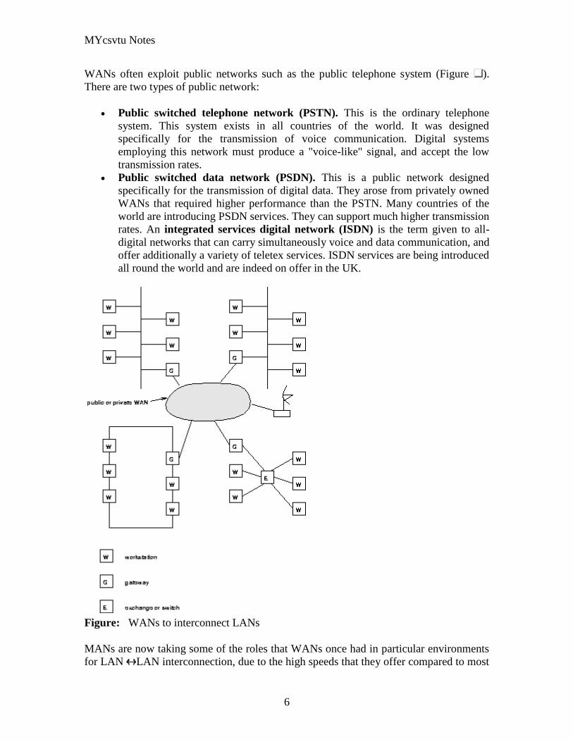
MYcsvtu Notes
6
WANs often exploit public networks such as the public telephone system (Figure )
There are two types of public network
Public switched telephone network (PSTN) This is the ordinary telephone
system This system exists in all countries of the world It was designed
specifically for the transmission of voice communication Digital systems
employing this network must produce a voice-like signal and accept the low
transmission rates
Public switched data network (PSDN) This is a public network designed
specifically for the transmission of digital data They arose from privately owned
WANs that required higher performance than the PSTN Many countries of the
world are introducing PSDN services They can support much higher transmission
rates An integrated services digital network (ISDN) is the term given to all-
digital networks that can carry simultaneously voice and data communication and
offer additionally a variety of teletex services ISDN services are being introduced
all round the world and are indeed on offer in the UK
Figure WANs to interconnect LANs
MANs are now taking some of the roles that WANs once had in particular environments
for LAN LAN interconnection due to the high speeds that they offer compared to most
MYcsvtu Notes
7
PSTNs and PSDNs eg FDDI and DQDB offer 100Mbs whereas a PSTN line may
offer say 192Kbs with a fast modem
At the present time the worlds communication systems are in a state of flux Historically
digital computing equipment conformed to the requirements of the PSTN Now
increasingly analogue traffic such as voice and video is conforming to the requirements
of the PSDN
Public networks employ two types of switching Switching describes the method by
which the corresponders are connected A circuit switched network (CSN) establishes a
connection through the network that is then used exclusively by the two correspondents
(Of course only in 19th century telephone exchanges is the switching actually current
driven) The PSTN is a circuit switched network A packet switched network (PSN)
divides the message into packets that are addressed to the recipient The packets are then
forwarded through the network together with many other packets These are locally
distributed on arrival The Post Office is a packet switched network More relevantly
LAN communication is exclusively via a PSN The outstanding advantage of the PSN is
that the two correspondents can communicate at different rates permitting much more
efficient use of the communication channel
The Communications Channel
A communication channel can be simplex in which only one party can transmit full-
duplex in which both correspondents can transmit and receive simultaneously or half-
duplex in which the correspondents alternate between transmitting and receiving states
(such as conversing adults) Even though the channel might be capable of supporting full-
duplex communication if the corresponding entities are not capable of transmitting and
receiving simultaneously the communications system will be half-duplex (as in the
example of the conversing adults)
Communication between two entities can be considered either in-band or out-of-band
depending on context In-band communication is communication which occurs via the
primary channel between the communicating entities Out-of-band communication occurs
via an alternative channel which is not considered to be the primary channel between the
entities
Which channel is primary and which is an alternate depends on context and the existence
of an alternative channel In the case of a conversation between two people the primary
channel could consist of verbal communication while the alternate channel consists of
visual body language Of course if emotions rise these two channels might reverse roles
with body language becoming the primary channel
MYcsvtu Notes
8
Simplex communication
From Wikipedia the free encyclopedia
Jump to navigation search
Simplex communication is a name for a type of communication circuit There are two
(contradictory) definitions that have been used for the term In both cases the other
definition is referred to as half duplex
Contents
[hide]
1 One way at a time
2 One way only
o 21 Examples according to ANSI definition
3 References
4 See also
One way at a time
According to the ITU-T definition a simplex circuit is one where all signals can flow in
only one direction at a time This was also the way Western Union used the term when
describing the duplex and simplex capacity of their new transatlantic telegraph cable
completed between Newfoundland and the Azores in 1928[1]
The same definition for a
simplex radio channel was used by the National Fire Protection Association in 2002[2]
One way only
According to the ANSI definition a simplex circuit is one where all signals can flow in
only one direction These systems are often employed in broadcast networks where the
receivers do not need to send any data back to the transmitterbroadcaster
To put it simply you wont find your radio receiver actually sending out any information
all it does is receive so information moves one way only from the radio broadcasting
station to your radio receiver
Half-Duplex
MYcsvtu Notes
9
A simple illustration of a half-duplex communication system
A half-duplex system provides for communication in both directions but only one
direction at a time (not simultaneously) Typically once a party begins receiving a signal
it must wait for the transmitter to stop transmitting before replying
An example of a half-duplex system is a two-party system such as a walkie-talkie style
two-way radio wherein one must use Over or another previously designated command
to indicate the end of transmission and ensure that only one party transmits at a time
because both parties transmit on the same frequency A good analogy for a half-duplex
system would be a one lane road with traffic controllers at each end Traffic can flow in
both directions but only one direction at a time with this being regulated by the traffic
controllers
Note that this is one of two contradictory definitions for half-duplex This
definition matches the ANSI standard For more detail see Simplex
communication
Full-Duplex
A simple illustration of a full-duplex communication system
A full-duplex system allows communication in both directions and unlike half-duplex
allows this to happen simultaneously Land-line telephone networks are full-duplex since
they allow both callers to speak and be heard at the same time A good analogy for a full-
duplex system would be a two lane road with one lane for each direction
Examples Telephone Mobile Phone etc
MYcsvtu Notes
10
Two way radios can be for instance designed as full-duplex systems which transmit on
one frequency and receive on a different frequency This is also called frequency-division
duplex Frequency-division-duplex systems can be extended to farther distances using
pairs of simple repeater stations owing to the fact the communications transmitted on any
one frequency always travels in the same direction
Full-duplex Ethernet connections work by making simultaneous use of all four physical
pair of twisted cable (which are inside the insulation) where two pair are used for
receiving packets and two pair are using for sending packets to a directly connected
device This effectively makes the cable itself a collision-free environment and
theoretically doubles the maximum bandwidth that can be supported by the connection
Channel Characteristics
A communications channel may be described in terms of its characteristic properties
These channel characteristics includebandwidth (how much information can be
conveyed across the channel in a unit of time commonly expressed in bits per second or
bps7 ) quality (how reliably can the information be correctly conveyed across the
channel commonly in terms of bit error rate or BER8 ) and whether the channel is
dedicated (to a single source) or shared (by multiple sources)
Obviously a higher bandwidth is usually a good thing in a channel because it allows more
information to be conveyed per unit of time High bandwidths mean that more users can
share the channel depending on their means of accessing it High bandwidths also allow
more demanding applications (such as graphics) to be supported for each user of the
channel
The capability of a channel to be shared depends of course on the medium used A shared
channel could be likened to a school classroom where multiple students might attempt to
simultaneously catch the teachers attention by raising their hand the teacher must then
arbitrate between these conflicting requests allowing only one student to speak at a time
Reliability of communication is obviously important A low quality channel is prone to
distorting the messages it conveys a high quality channel preserves the integrity of the
messages it conveys Depending on the quality of the channel in use between
communicating entities the probability of the destination correctly receiving the message
from the source might be either very high or very low If the message is received
incorrectly it needs to be retransmitted
If the probability of receiving a message correctly across a channel is too low the system
(source channel message destination) must include mechanisms which overcome the
errors introduced by the low quality channel Otherwise no useful communication is
possible over that channel These mechanisms are embodied in the communication
protocols employed by the corresponding entities
MYcsvtu Notes
11
The effective bandwidth describes what an application experiences and depends on the
quality of service (QOS) provided by the channel For example modems scale back their
transmission speed based largely on their perception of channel quality in order to
optimally use the transmission medium
In general shared and reliable channels are more resource efficient than those which
enjoy neither of these characteristics Shared channels enjoy greater efficiency than
dedicated ones because most data communication is bursty in nature with long idle
periods punctuated by brief message transmissions Reliable channels are more efficient
than unreliable ones because retransmissions are not required as often (because there are
fewer transmission-induced errors)
The OSI Reference Model
The Open Systems Interconnect (OSI) reference model is commonly used to describe in
an abstract manner the functions involved in data communication This model originally
conceived in the International Organization for Standardization (ISO) defines data
communications functions in terms of layers
In the OSI reference model each layer is responsible for certain basic functions such as
getting data from one device to another or from one application on a computer to another
The functions at each layer both depend and build on the functions-called services-
provided by the layers below it Communication between peer entities at a given layer is
done via one or more protocols this communication is invoked via the interface with the
layer below
The OSI reference model is depicted in Table 01 Successful communication between
two applications depends on successful functions at all seven layers In terms of
implementation it is possible for some layers to be trivial in the end what is required
depends on the needs of the applications (and people) engaged in communication
Table 01 OSI Reference Model
Layer Title
7 Application
Higher Layers 6 Presentation
5 Session
4 Transport
MYcsvtu Notes
12
3 Network
Lower Layers 2 Data Link
1 Physical
We must emphasize that the definition of a layered data communication architecture is
only an abstraction The intent of this definition is to unambiguously describe the
functions involved in data communication in a way which allows different systems to be
compared The OSI reference model definition is intended to neither imply nor constrain
the implementation of any communication system
Although various companies and standards bodies have created different layered
communications models the OSI reference model remains the universally-accepted
common denominator for abstract definition Other models define the layer functions
somewhat differently and often have fewer than seven layers In some cases constituent
protocols were specified before the abstract models defining the end-to-end
communication
We will now review the functions of the OSI layers and some of the primary protocols at
each layer9
Layer 1 - The Physical Layer
The physical layer functions include all physical aspects of communicating between two
directly-connected physical entities Typically these physical properties include
electromechanical characteristics of the medium or link between the communicating
physical entities such as connectors voltages transmission frequencies etc This layer
summarizes the physics which underlie the communication path
The essential service provided by the physical layer consists of an unstructured bit
stream which can be used by higher layers to provide the basis for higher layer
communication services An example of a physical layer is the ink on paper used by this
book to convey information Another example is the radio frequencies used in a wireless
communications system
Layer 2 - The Data Link Layer
The data link layer accepts the unstructured bit stream provided by the physical layer and
provides reliable transfer of data between two directly-connected Layer 2 entities
Directly-connected means that the Layer 2 entities communication path does not
require another Layer 2 entity However this does not imply a dedicated path in the case
MYcsvtu Notes
13
of Ethernet many Layer 2 entities can be sharing a common (physical) medium such as a
coaxial cable or a 10BASE-T hub
Layer 2 functionality is limited in scope-delivery of messages over a local area It could
be likened to an intra-office correspondence between co-workers there is a need for
reliability but addressing is relatively simple Local area networks (LANs) operate at
Layer 2
The data link layer is itself conceptually subdivided into two sublayers-medium access
control and logical link control-which more specifically define the primary aspects of
data link layer functionality However this conceptual partitioning by the IEEE 802
committee is somewhat arbitrary and subject to debate
The MAC Sublayer
The medium access control (MAC) sublayer is closely associated with the physical layer
and defines the means by which the physical channel (medium) may be accessed It
coordinates the attempts to seize a shared channel by multiple MAC entities much as a
school teacher must arbitrate between pupils conflicting desires to speak The MAC layer
commonly provides a limited form of error control especially for any header information
which defines the MAC-level destination and higher-layer access mechanism
Ethernet (IEEE 8023) is a prime example of a shared medium with a defined MAC
sublayer functionality The shared medium in Ethernet has traditionally consisted of a
coaxial cable into which multiple entities were tapped as depicted in Figure 05
Although this topology still applies conceptually a hub and spoke medium is now
typically used in which the earlier coaxial cable has been physically collapsed into a hub
device
Figure 05 Ethernet MAC System
11
As a contention medium Ethernet defines how devices sense a channel for its
availability wait when it is busy seize the channel when it becomes available and back-
off for a random length of time following a collision with another simultaneously
MYcsvtu Notes
14
transmitting device On a shared channel such as Ethernet only a single entity can
transmit at a time or messages will be garbled
Not all shared channels involve contention A prime example of a contentionless shared
medium is token ring (IEEE 8025) in which control of the channel is rotated between
the devices sharing the channel in a deterministic round-robin manner Conceptually
control of the channel is given to the entity currently possessing a token If the device
has nothing to transmit it passes the token to the next device attached to the topological
ring depicted in Figure 06
Figure 06 Token Ring MAC System
11
IEEE-defined MAC sublayer addresses are six bytes long and permanently assigned to
each device typically called a network interface card orNIC The IEEE administers the
assignment of these addresses in blocks to manufacturers to assure the global uniqueness
that the MAC sublayer protocols rely on for plug Ocircn play network setup Each
manufacturer must assure individual device identifier uniqueness within their assigned
block
The LLC Sublayer
The logical link control (LLC) sublayer is responsible for reliable transfer of messages-
called frames or more formally link protocol data units (LPDUs)-between two directly-
connected Layer 2 entities Functions needed to support this reliable transfer include
framing (indicating where a Layer 2 message begins and ends) sequence control error
control and flow control
MYcsvtu Notes
15
The degree to which sequence error and flow control are provided by the LLC sublayer
is determined by whether the link protocol is connection-oriented or connectionless A
connectionless link protocol provides little if any support for these functions A
connection-oriented link might use a windowing technique for these functions in which
frames are individually numbered and acknowledged by their sequence number with
only a few such frames outstanding at any time
The connection-oriented functions of sequencing error and flow control provide a
foundation for services provided by higher layers As mentioned earlier not all layer or
sublayer functions are explicitly designed or implemented in any given system Provision
of these functions depends on the services required by higher layers
If the connection-oriented functions of the LLC sublayer are not implemented they must
be performed by higher layers for reliable end-to-end communication If these functions
are provided by several layers they might be somewhat redundant and add unnecessary
overhead (inefficiency) to the system In the worst case redundant provision of these
functions at multiple layers could serve cross purposes and actually degrade overall
system performance
An example of a connectionless LLC protocol is frame relay (T1617 618) which
defines point-to-point links with switches connecting individual links in a mesh topology
In a frame relay network endpoints are connected by a series of links and switches
Because frame relay is defined in terms of the links between frame relay access devices
(FRADs) and switches and between switches themselves it is an LLC protocol
Connectionless Layer 2 protocols are best suited for high quality transmission media
With high quality transmission media errors are rarely introduced in the transmission
between network layer entities and discovery of and recovery from errors is most
efficiently handled by the communicating hosts In this case it is better to move the
packets quickly across the traversed subnetworks from source to destination rather than
checking for errors at Layer 2
Frame relay is derived from the X25 (ISO 8208) protocol which spans Layers 2 and 3
X25 is a connection-oriented packet-switching technology which defines how
neighboring packet switches exchange data with one another in a reliable manner from
end-to-end Frame relay simply removes the connection-oriented functions of error and
sequence control however congestion control functions are provided in frame relay to
prevent the total traffic seen at any point in the network from overwhelming it
Connection-oriented Layer 2 protocols are best suited for low quality transmission media
where it is more efficient and cost-effective to discover and recover from errors as they
occur on each hop than to rely on the communicating hosts to perform error recovery
functions With ever-increasing quality of transmission facilities and decreasing costs of
computation capability at hosts the need for connection-oriented network layer protocols
is diminishing However X25 remains popular outside of North America where it has
been tariffed at levels which encourage its use
MYcsvtu Notes
16
End-to-end communications may be via shared or dedicated facilities or circuits Shared
facilities involve the use of packet switching technology to carry messages from end-to-
end messages are subdivided as necessary into packets which share physical and logical
channels with packets from various sources to various destinations Packet switching is
almost universally used in data communications because it is more efficient for the bursty
nature of data traffic
On the other hand some applications require dedicated facilities from end-to-end because
they are isochronous (eg voice) or bandwidth-intensive (eg large file transfer) This
mode of end-to-end circuit dedication is called circuit switched communication Because
the facilities are dedicated to a single user this tends to be much more expensive than the
packet switched mode of communication But some applications need it-it is an economic
trade-off
Dedicated circuits are a rather extreme form of connection-oriented protocol requiring
the same setup and tear-down phases prior to and following communication If the circuit
setup and tear-down is statically arranged (ie out-of-band) it is referred to as a
permanent virtual circuit or PVC If the circuit is dynamically setup and torn-down in-
band it is referred to as a switched virtual circuit or SVC
Layer 3 - The Network Layer
The network layer defines the functions necessary to support data communication
between indirectly-connected entities It provides the capability of forwarding messages
from one Layer 3 entity to another until the final destination is reached
The network layer introduces another layer of abstraction to the data communications
model It moves messages-called packets or more formally network protocol data units
(NPDUs)-between communicating Layer 3 entities-called end systems nodes or hosts
Network layer functions include route determination or routing and forwarding of
packets to their final destinations
In order to forward a packet to its destination host routing information must be provided
to theintermediate systems (ISs) or routers responsible for forwarding packets to their
respective destinations This routing information includes the address of the destination
which is contained in each packet The next hop to be traversed by the packet is
determined primarily by this destination address We will talk more about addressing and
routing in Chapter 1
This packet forwarding and routing is accomplished independent of both the media and
transmission types used at any step along the way The unimportance of local topology to
the network layer is demonstrated by the common use of cloud diagrams to depict
networks as in Figure 07 Since the network layer is concerned with getting packets
across many local networks called subnetworks its title would be more accurate if it
were the Internetwork Layer
MYcsvtu Notes
17
Figure 07 Network Layer ``Cloud
Diagram
11
The network layer functionality is global in scope-delivery of messages over a wide area
It could be likened to the postal system in which correspondence is passed from location
to location until it eventually reaches the destination address on the envelope10
The
network layer is the domain of wide area networks (WANs)
In order for routers to know how (ie on which link) to forward packets they must have
some knowledge of network topology This knowledge may be complete or partial and is
dynamically created and maintained via routing protocols used by routers to share their
knowledge of network topology with each other Routing is essentially the reduction of
global internetwork topology to local hop-by-hop routing decisions made
independently by each router
As with Layer 2 Layer 3 protocols may be connection-oriented or connectionless A
connection-oriented Layer 3 protocol such as X25 (ISO 8208) operates more statically
The basic idea is that an end-to-end route (X25 virtual connection) is established from
the originating data terminal equipment (DTE) to data communications equipment
(DCE) from DCE to DCE through the network then from the last DCE to the
terminating DTE this is the call setup Packets are then transmitted via this prearranged
route with all packets following the same path through the network Finally the route is
torn down (release) and packets cease flowing
X25 operation is like a phone call because it is a phone call X25 Layer 3 operation
assumes that a reliable connection-oriented service is provided by Layer 2 (also defined
by the X25 standard) although it does provide flow control via sequence numbers
Connectionless Layer 3 protocols such as the ever popular internet protocol (IP)(RFC11
791 and 792) and its ISO counterpart connectionless network protocol (CLNP) (ISO
MYcsvtu Notes
18
8473) route packets dynamically There is no prearranged path which is followed by
subsequent packets flowing from one host to another Instead each packet is individually
routed through a routing mesh there is no reason to believe that sequential packets
flowing between hosts will follow the same path So sequence errors may be introduced
at Layer 3 which must be corrected by a higher layer entity
Connectionless data packets are commonly referred to as datagrams and the service
provided by connectionless Layer 3 protocols is referred to as datagram service Stateless
datagram service is simpler for Layer 3 entities than connection-oriented network layer
services Because there is no state information to maintain dynamic routing protocols can
be used If a router fails during the dialogue between two communicating hosts
neighboring routers will discover this via the routing protocols and find alternate routes
which bypass the failed router
There seems to be a fair amount of ambiguity between the network layer and the LLC
sublayer Both can provide connection-oriented or connectionless services to higher
layers To a large extent if Layer 3 is explicitly implemented there is no need for an
LLC sublayer The primary difference is in scope-LLC addresses and protocols are
oriented toward a more local environment whereas network layer addresses and protocols
are global in scope
Excellent references to routing and forwarding of data packets can be found in [PERL92]
and [STEN95]
Layer 4 - The Transport Layer
The transport layer is concerned with getting Layer 4 messages-called segments or more
formally transport protocol data units (TPDUs) -from source to destination in a reliable
manner The perspective of Layer 4 is of end-to-end communications rather than the hop-
by-hop perspective of Layer 3 Layer 4 assumes that packets can be moved from network
entity to network entity eventually getting to the final destination host How this is
accomplished is of no concern to Layer 4 functionality
Like other layers transport layer protocols can be either connection-oriented or
connectionless depending on the services required by higher layers A common
implementation of Layers 3 and 4 involves a connection-oriented transport layer protocol
running over a connectionless network layer protocol such as the ubiquitous TCPIP
protocol suite In this instance the communicating hosts maintain state information on
communications with each other to determine when and what to send This state
information defines the connection between the communicating Layer 4 entities
The general idea here is that two communicating hosts need not be concerned with the
topology of the internetwork which lies between them They only need to know the state
of their pairwise communication If part of the intervening internetwork cloud suffers a
failure the Layer 3 entities (routers) will deal with it and recover dynamically Aside
MYcsvtu Notes
19
from potential retransmission of any lost segments the hosts Layer 4 entries do not have
to be at all concerned with routing and recovery activities at Layer 3
In the IP protocol suite the primary connectionless Layer 4 protocol is the User
Datagram Protocol (UDP)(RFC 768) which is carried by IP the primary connection-
oriented protocol is the Transmission Control Protocol (TCP)(RFC 793) The ISO world
defines five classes of transport layer protocol beginning with Class 0 (TP-0) for
connectionless operation and range up to Class 4 (TP-4)(ISO 8073) for connection-
oriented operation
Layer 5 - The Session Layer
The session layer provides a control structure for communication between applications
on hosts The communication at layer 5 is called a session which defines the relative
timing of communications between the hosts applications Synchronization of
communicating applications comes into play when coordinated timing of corresponding
events at the endpoints is imperative such as in financial transactions
Remember layers define communication functions not implementations It is unlikely
that a session layer would be explicitly implemented as a stand-alone program although
its functions would be implemented somewhere Session layer functions depend on the
reliability of communications between the endpoints and session layer functions must
therefore be implemented above Layer 4
Layer 6 - The Presentation Layer
The presentation layer performs any necessary data transformations or formatting
required by the end applications Functions provided by the presentation layer include
data compression file formatting and encryption Common data formatting is important
because it allows the same application file to be accessed by the application running on
different computer platforms This book is itself the product of an application running on
different platforms with common files being modified via these different platforms
Abstract Syntax Notation (ASN1) is commonly used to specify data values in a way
which allows processors to communicate independent of their varying native integer
sizes bit orderings (big or little endian) character sets etc ASN1 is a transfer syntax a
presentation layer formatting which appears frequently in the CDPD specification for
unambiguous definition of network management accounting limited size messaging and
other functions
An example of ASN1 encoding from an accounting Traffic Matrix Segment in the
CDPD specification is the following
MYcsvtu Notes
20
TrafficType = INTEGER
registration (0)
deregistration (1)
ip(2)
clnp(3)
Layer 7 - The Application Layer
The application layer provides the services which directly support an application running
on a host These services are directly accessible by an application via common well-
known application program interfaces (APIs) which can actually occur at many layers
Examples of layer 7 services include FTP (file transfer protocol) Telnet and SNMP
(simple network management protocol) Most network management activities are based
on the services provided by layer 7 application entities which in turn rely on lower layer
services to be able to perform their functions
7 Application ECHO ENRP FTP Gopher HTTP NFS RTSP SIP SMTP SNMP
SSH Telnet Whois XMPP
6 Presentation XDR ASN1 SMB AFP NCP
5 Session ASAP TLS SSL ISO 8327 CCITT X225 RPC NetBIOS ASP
4 Transport TCP UDP RTP SCTP SPX ATP IL
3 Network IP ICMP IGMP IPX OSPF RIP IGRP EIGRP ARP RARP X25
2 Data Link Ethernet Token ring HDLC Frame relay ISDN ATM 80211 WiFi
FDDI PPP
1 Physical 10BASE-T 100BASE-T 1000BASE-T SONETSDH G709 T-
carrierE-carrier various 80211 physical layers
The TCPIP Reference Model
The TCPIP reference model is the network model used in the current Internet
architecture [19] It has its origins back in the 1960s with the grandfather of the Internet
the ARPANET This was a research network sponsored by the Department of Defense in
the United States The following were seen as major design goals
ability to connect multiple networks together seamlessly
ability for connections to remain intact as long as the source and destination
machines were functioning
MYcsvtu Notes
21
to be built on flexible architecture
The reference model was named after two of its main protocols TCP (Transmission
Control Protocol) [12] and IP (Internet Protocol)
They choose to build a packet-switched network based on a connectionless internetwork
layer
Figure 21 TCPIP Network Protocol
A detailed description of the reference model is beyond the scope of this document and
project The basic idea of the networking system is to allow one application on a host
computer to talk to another application on a different host computer
The application forms its request then passes the packet down to the lower layers which
add their own control information either a header or a footer onto the packet Finally the
packet reaches the physical layer and is transmitted through the cable onto the destination
host The packet then travels up through the different layers with each layer reading
deciphering and removing the header or footer that was attached by its counterpart on the
originating computer Finally the packet arrives at the application it was destined for
Even though technically each layer communicates with the layer above or below it the
process can be viewed as one layer talking to its partner on the host as figure 21 shows
The Host-to-Network Layer
The Host-to-Network layer interfaces the TCPIP protocol stack to the physical network
The TCPIP reference model does not specify in any great detail the operation of this
layer except that the host has to connect to the network using some protocol so it can
send IP packets over it
As it is not officially defined it varies from implementation to implementation with
vendors supplying their own version
MYcsvtu Notes
22
The Network Layer
The job of the network layer is to inject packets into any network and have them travel
independently to the destination The layer defines IP (Internet Protocol) for its official
packet format and protocol Packet routing is a major job of this protocol
The Transport Layer
The transport layer is the interface between the application layer and the complex
hardware of the network It is designed to allow peer entities on the source and
destination hosts to carry on conversations
Data may be user data or control data Two modes are available full-duplex and half
duplex In full-duplex operation both sides can transmit and receive data simultaneously
whereas in half duplex a side can only send or receive at one time
Interaction between the transport layer and the layers immediately above and below are
shown in figure 22 Any program running in the application layer has the ability to send
a message using TCP or UDP which are the two protocols defined for the transport layer
The application can communicate with the TCP or the UDP service whichever it
requires Both the TCP and UDP communicate with the Internet Protocol in the internet
layer In all cases communication is a two way process The applications can read and
write to the transport layer The diagram only shows two protocols in the transport layer
TTCP will also reside in this layer between the other two protocols and function in the
same manner
Figure 22 Interaction with Application Transport and Internet Layers
A message to be sent originates in the application layer This is then passed down onto
the appropriate protocol in the transport layer These protocols add a header to the
message for the corresponding transport layer in the destination machine for purposes of
reassembling the message The segment is then passed onto the internet layer where the
Internet Protocol adds a further header Finally the segment is passed onto the physical
MYcsvtu Notes
23
layer a header and a trailer are added at this stage Figure 23 shows the structure of the
final segment being sent
Figure 23 Transmitted Segment from TCPIP Network
The Application Layer
The original TCPIP specification described a number of different applications that fit
into the top layer of the protocol stack These applications include Telnet FTP SMTP
and DNS
Telnet is a program that supports the TELNET [13] protocol over TCP TELNET is a
general two-way communication protocol that can be used to connect to another host and
run applications on that host remotely
FTP (File Transfer Protocol) [14] is a protocol that was originally designed to promote
the sharing of files among computer users It shields the user from the variations of file
storage on different architectures and allows for a reliable and efficient transfer of data
SMTP (Simple Mail Transport Protocol) [15] is the protocol used to transport electronic
mail from one computer to another through a series of other computers along the route
DNS [10] (Domain Name System) resolves the numerical address of a network node into
its textual name or vice-versa It would translate wwwyahoocom to 2047117771 to
allow the routing protocols to find the host that the packet is destined for
What is a Topology
The physical topology of a network refers to the configuration of cables computers and
other peripherals Physical topology should not be confused with logical topology which
is the method used to pass information between workstations Logical topology was
discussed in the Protocol chapter
Main Types of Physical Topologies
The following sections discuss the physical topologies used in networks and other related
topics
Linear Bus
MYcsvtu Notes
24
Star
Star-Wired Ring
Tree
Considerations When Choosing a Topology
Summary Chart
Linear Bus
A linear bus topology consists of a main run of cable with a terminator at each end (See
fig 1) All nodes (file server workstations and peripherals) are connected to the linear
cable Ethernet and LocalTalk networks use a linear bus topology
Fig 1 Linear Bus topology
Advantages of a Linear Bus Topology
Easy to connect a computer or peripheral to a linear bus
Requires less cable length than a star topology
Disadvantages of a Linear Bus Topology
Entire network shuts down if there is a break in the main cable
Terminators are required at both ends of the backbone cable
Difficult to identify the problem if the entire network shuts down
Not meant to be used as a stand-alone solution in a large building
Star
A star topology is designed with each node (file server workstations and peripherals)
connected directly to a central network hub or concentrator (See fig 2)
Data on a star network passes through the hub or concentrator before continuing to its
destination The hub or concentrator manages and controls all functions of the network It
also acts as a repeater for the data flow This configuration is common with twisted pair
cable however it can also be used with coaxial cable or fiber optic cable
MYcsvtu Notes
25
Fig 2 Star topology
Advantages of a Star Topology
Easy to install and wire
No disruptions to the network then connecting or removing devices
Easy to detect faults and to remove parts
Disadvantages of a Star Topology
Requires more cable length than a linear topology
If the hub or concentrator fails nodes attached are disabled
More expensive than linear bus topologies because of the cost of the
concentrators
The protocols used with star configurations are usually Ethernet or LocalTalk Token
Ring uses a similar topology called the star-wired ring
Star-Wired Ring
A star-wired ring topology may appear (externally) to be the same as a star topology
Internally the MAU (multistation access unit) of a star-wired ring contains wiring that
allows information to pass from one device to another in a circle or ring (See fig 3) The
Token Ring protocol uses a star-wired ring topology
Tree
A tree topology combines characteristics of linear bus and star topologies It consists of
groups of star-configured workstations connected to a linear bus backbone cable (See fig
MYcsvtu Notes
26
4) Tree topologies allow for the expansion of an existing network and enable schools to
configure a network to meet their needs
Fig 4 Tree topology
Advantages of a Tree Topology
Point-to-point wiring for individual segments
Supported by several hardware and software venders
Disadvantages of a Tree Topology
Overall length of each segment is limited by the type of cabling used
If the backbone line breaks the entire segment goes down
More difficult to configure and wire than other topologies
5-4-3 Rule
A consideration in setting up a tree topology using Ethernet protocol is the 5-4-3 rule
One aspect of the Ethernet protocol requires that a signal sent out on the network cable
reach every part of the network within a specified length of time Each concentrator or
repeater that a signal goes through adds a small amount of time This leads to the rule that
between any two nodes on the network there can only be a maximum of 5 segments
connected through 4 repeatersconcentrators In addition only 3 of the segments may be
populated (trunk) segments if they are made of coaxial cable A populated segment is one
which has one or more nodes attached to it In Figure 4 the 5-4-3 rule is adhered to The
MYcsvtu Notes
27
furthest two nodes on the network have 4 segments and 3 repeatersconcentrators
between them
This rule does not apply to other network protocols or Ethernet networks where all fiber
optic cabling or a combination of a fiber backbone with UTP cabling is used If there is a
combination of fiber optic backbone and UTP cabling the rule is simply translated to 7-
6-5 rule
] Mesh
Full
Fully Connected The type of network topology in which each of the nodes of the network is
connected to each of the other nodes in the network with a point-to-point link ndash
this makes it possible for data to be simultaneously transmitted from any single
node to all of the other nodes
Note The physical fully connected mesh topology is generally too costly and
complex for practical networks although the topology is used when there are only
a small number of nodes to be interconnected[3]
Partial
Partially Connected The type of network topology in which some of the nodes of the network are
connected to more than one other node in the network with a point-to-point link ndash
this makes it possible to take advantage of some of the redundancy that is
provided by a physical fully connected mesh topology without the expense and
complexity required for a connection between every node in the network
Note In most practical networks that are based upon the physical partially
connected mesh topology all of the data that is transmitted between nodes in the
network takes the shortest path between nodes except in the case of a failure or
break in one of the links in which case the data takes an alternate path to the
destination ndash this implies that the nodes of the network possess some type of
logical routing algorithm to determine the correct path to use at any particular
time
[edit] Hybrid Network Topologies
The hybrid topology is a type of network topology that is composed of one or more
interconnections of two or more networks that are based upon different physical
topologies or a type of network topology that is composed of one or more
interconnections of two or more networks that are based upon the same physical
topology but where the physical topology of the network resulting from such an
interconnection does not meet the definition of the original physical topology of the
interconnected networks (eg the physical topology of a network that would result from
an interconnection of two or more networks that are based upon the physical star
topology might create a hybrid topology which resembles a mixture of the physical star
MYcsvtu Notes
28
and physical bus topologies or a mixture of the physical star and the physical tree
topologies depending upon how the individual networks are interconnected while the
physical topology of a network that would result from an interconnection of two or more
networks that are based upon the physical distributed bus network retains the topology of
a physical distributed bus network)
Star-Bus A type of network topology in which the central nodes of one or more individual
networks that are based upon the physical star topology are connected together
using a common bus network whose physical topology is based upon the
physical linear bus topology the endpoints of the common bus being terminated
with the characteristic impedance of the transmission medium where required ndash
eg two or more hubs connected to a common backbone with drop cables
through the port on the hub that is provided for that purpose (eg a properly
configured uplink port) would comprise the physical bus portion of the physical
star-bus topology while each of the individual hubs combined with the
individual nodes which are connected to them would comprise the physical star
portion of the physical star-bus topology
Star-of-Stars
Hierarchical Star A type of network topology that is composed of an interconnection of individual
networks that are based upon the physical star topology connected together in a
hierarchical fashion to form a more complex network ndash eg a top level central
node which is the hub of the top level physical star topology and to which other
second level central nodes are attached as the spoke nodes each of which in
turn may also become the central nodes of a third level physical star topology
Notes 1) The physical hierarchical star topology is not a combination of the physical
linear bus and the physical star topologies as cited in some texts as there is no
common linear bus within the topology although the top level hub which is the
beginning of the physical hierarchical star topology may be connected to the
backbone of another network such as a common carrier which is topologically
not considered to be a part of the local network ndash if the top level central node is
connected to a backbone that is considered to be a part of the local network then
the resulting network topology would be considered to be a hybrid topology that
is a mixture of the topology of the backbone network and the physical hierarchical
star topology
2) The physical hierarchical star topology is also sometimes incorrectly referred
to as a physical tree topology since its physical topology is hierarchical however
the physical hierarchical star topology does not have a structure that is determined
by a branching factor as is the case with the physical tree topology and therefore
nodes may be added to or removed from any node that is the hub of one of the
individual physical star topology networks within a network that is based upon the
physical hierarchical star topology
3) The physical hierarchical star topology is commonly used in outside plant
(OSP) cabling to connect various buildings to a central connection facility which
MYcsvtu Notes
29
may also house the demarcation point for the connection to the data transmission
facilities of a common carrier and in inside plant (ISP) cabling to connect
multiple wiring closets within a building to a common wiring closet within the
same building which is also generally where the main backbone or trunk that
connects to a larger network if any enters the building
Star-wired Ring A type of hybrid physical network topology that is a combination of the physical
star topology and the physical ring topology the physical star portion of the
topology consisting of a network in which each of the nodes of which the network
is composed are connected to a central node with a point-to-point link in a hub
and spoke fashion the central node being the hub and the nodes that are
attached to the central node being the spokes (eg a collection of point-to-point
links from the peripheral nodes that converge at a central node) in a fashion that is
identical to the physical star topology while the physical ring portion of the
topology consists of circuitry within the central node which routes the signals on
the network to each of the connected nodes sequentially in a circular fashion
Note In an 8025 Token Ring network the central node is called a Multistation
Access Unit (MAU)
Hybrid Mesh A type of hybrid physical network topology that is a combination of the physical
partially connected topology and one or more other physical topologies the mesh
portion of the topology consisting of redundant or alternate connections between
some of the nodes in the network ndash the physical hybrid mesh topology is
commonly used in networks which require a high degree of availability
Considerations When Choosing a Topology
Money A linear bus network may be the least expensive way to install a network
you do not have to purchase concentrators
Length of cable needed The linear bus network uses shorter lengths of cable
Future growth With a star topology expanding a network is easily done by
adding another concentrator
Cable type The most common cable in schools is unshielded twisted pair which
is most often used with star topologies
Summary Chart
Common Cable Common Protocol
Linear Bus Twisted Pair
Coaxial
Ethernet
LocalTalk
MYcsvtu Notes
30
Fiber
Star Twisted Pair
Fiber
Ethernet
LocalTalk
Star-Wired Ring Twisted Pair Token Ring
Tree
Twisted Pair
Coaxial
Fiber
Ethernet
Internet vs Web
The Internet and the World Wide Web are not synonymous the Internet is a collection of
interconnected computer networks linked by copper wires fiber-optic cables wireless
connections etc the Web is a collection of interconnected documents and other
resources linked by hyperlinks and URLs The World Wide Web is accessible via the
Internet as are many other services including e-mail file sharing and others described
below
The best way to define and distinguish between these terms is to understand the Internet
protocol suite This collection of protocols is organized into layers such that each layer
provides the foundation and the services required by the layer above In this conception
the term Internet refers to computer networks that all communicate with IP (Internet
protocol) and TCP (transfer control protocol) Once this networking structure is
established then other protocols can run ―on top These other protocols are sometimes
called services or applications Hypertext transfer protocol or HTTP is an application
layer protocol that links billions of files together into the World Wide Web
Common uses of the Internet
The World Wide Web
Through keyword-driven Internet research using search engines like Google
millions worldwide have easy instant access to a vast and diverse amount of
online information Compared to encyclopedias and traditional libraries the
World Wide Web has enabled a sudden and extreme decentralization of
information and data
Many individuals and some companies and groups have adopted the use of Web logs or
blogs which are largely used as easily-updatable online diaries Some commercial
organizations encourage staff to fill them with advice on their areas of specialization in
the hope that visitors will be impressed by the expert knowledge and free information
and be attracted to the corporation as a result One example of this practice is Microsoft
MYcsvtu Notes
31
whose product developers publish their personal blogs in order to pique the publics
interest in their work
For more information on the distinction between the World Wide Web and the Internet
itself mdash as in everyday use the two are sometimes confused mdash see Dark internet where
this is discussed in more detail
Remote access
The Internet allows computer users to connect to other computers and information stores
easily wherever they may be across the world They may do this with or without the use
of security authentication and encryption technologies depending on the requirements
This is encouraging new ways of working from home collaboration and information
sharing in many industries An accountant sitting at home can audit the books of a
company based in another country on a server situated in a third country that is remotely
maintained by IT specialists in a fourth These accounts could have been created by
home-working book-keepers in other remote locations based on information e-mailed to
them from offices all over the world Some of these things were possible before the
widespread use of the Internet but the cost of private leased lines would have made
many of them infeasible in practice
An office worker away from his desk perhaps the other side of the world on a business
trip or a holiday can open a remote desktop session into his normal office PC using a
secure Virtual Private Network (VPN) connection via the Internet This gives him
complete access to all his normal files and data including e-mail and other applications
while he is away
This concept is also referred to by some network security people as the Virtual Private
Nightmare because it extends the secure perimeter of a corporate network into its
employees homes this has been the source of some notable security breaches but also
provides security for the workers
Functions
File-sharing
Instant messaging
Internet fax
Search engine
World Wide Web
MYcsvtu Notes
32
Intranets
What are Intranets
bull Intranet is Intra+ Net so an Intranet is an internal or private Internet used strictly
within the confines of a company university or organization Inter means
between or among hence the difference between the Internet and an Intranet
Some formal definitions of Intranets
bull Brown amp Duguid ―Intranets help present and
circulate boundary objects
bull Choo Detlor amp Turnbull ―Intranetshellip support the creation sharing and use of
knowledge
bull Stenmark ―Intranets are organizationally
restricted
A technical definition
bull An Intranet is a network based on the internet TCPIP open standard An intranet
belongs to an organization and is designed to be accessible only by the
organizations members employees or others with authorization An intranets
Web site looks and act just like other Web sites but has a firewall surrounding it
to fend off unauthorized users
Design Of Intranets
Steps
bull Analyze the organizationlsquos information ecology
bull Identify the typical problems experienced by users
bull Analyze the information behaviors of these set of users
bull Create value added processes to resolve the problems of users and to improve the
Information Ecology
Value Added Processes
bull Intranets may be designed to improve the organizational information ecology
MYcsvtu Notes
33
bull Intranets provide a unified information space in which users can communicate
and collaborate with others
bull intranet applications and services may add value by supporting the organizationlsquos
knowledge creating and decision making process
Two Models of Online Environments
Centralized
Distributed
Centralized Environments
bull Before the web the centralized model was all we had (examples include
CompuServe Prodigy)
bull On the web centralized models include site-based services such as Yahoo
bull Most (all) college and university services are offered using the centralized
model
MYcsvtu Notes
34
bull But centralized environments are static inflexible expensive
Distributed Environments
bull The World Wide Web is an example of a distributed environment
bull Resources access are not centralized but scattered around the world
ndash Resources in the form of a network of connected (via DNS) web servers
ndash Access in the form of a network of connected (via DNS) internet service
providers
ndash Users in the form of individualized and connected (via HTTP) web
browsers
bull The big issue ndash integration ndash that is making different systems work together
Design Principles
Network Design Principles
ndash Specifies how networks differ from traditional learning
ndash The idea is that each principle confers an advantage over non-network
systems
ndash Can be used as a means of evaluating new technology
1 Decentralize
ndash Centralized networks have a characteristic starlsquo shape
bull Some entities have many connections
bull The vast majority have few
bull Eg broadcast network teacher in a classroom
ndash Decentralized networks form a mesh
bull The weight of connections flow is distributed
bull Balanced load = more stable
bull Foster connections between entities fill outlsquo the star
Distribute
ndash Network entities reside in different physical locations
bull Reduces risk of network failure
bull Reduces need for major infrastructure such as powerful servers
large bandwidth massive storage
ndash Examples
bull Peer-to-peer networks such as Kazaa Gnutella
bull Content syndication networks such as RSS
ndash Emphasis is on sharing not copying
bull Locallsquo copies are temporary
MYcsvtu Notes
35
Computer Graphics
Computer Graphics is about animation (films)
Games are very important in Computer Graphics
Medical Imaging is another driving force
Computer Aided Design too
Graphics Definitions
bull Point
ndash a location in space 2D or 3D
ndash sometimes denotes one pixel
bull Line
ndash straight path connecting two points
ndash infinitesimal width consistent density
ndash beginning and end on points
bull Vertex
ndash point in 3D
bull Edge
ndash line in 3D connecting two vertices
bull PolygonFaceFacet
ndash arbitrary shape formed by connected vertices
ndash fundamental unit of 3D computer graphics
bull Raster
ndash derived from TV systems for a row of pixels
ndash commonly referred to as a scanline
ndash does influence algorithms ndash reducing memory requirements parallelism
etc
ndash is the derivation of rasterization scan-line algorithms
Displays
bull Most desktop displays use a cathode ray tube (CRT) while portable computing
devices such as laptops incorporate liquid crystal display (LCD)
bull Because of their slimmer design and smaller energy consumption monitors using
LCD technologies are beginning to replace the venerable CRT on many desktops
Cathode-Ray Tubes
MYcsvtu Notes
36
bull Classical output device is a monitor
bull Cathode-Ray Tube (CRT)
ndash Invented by Karl Ferdinand Braun (1897)
ndash Beam of electrons directed from cathode (-)to phosphor-coated
(fluorescent) screen (anode (+))
ndash Directed by magnetic focusing and deflection coils (anodes) in vacuum
filled tube
ndash Phosphor emits photon of light when hit by an electron of varied
persistence (long 15-20 ms for texts short lt 1ms for animation)
ndash Refresh rate (50-60 Hz 72-76 Hz) to avoid flicker trail
ndash Phosphors are organic compounds characterized by their persistence and
their color (blue red green)
Cathode-Ray Tubes
bull Cathode-Ray Tube (CRT)
ndash Horizontal deflection and vertical deflection direct the electron beam to
any point on the screen
ndash Intensity knob regulates the flow of electrons by controlling the voltage at
the control grid (high voltage reduces the electron density and thus
brightness)
ndash Accelerating voltage from positive coating inside screen (anode screen) or
an accelerating anode
bull Image maintenance
ndash Charge distribution to store picture information
OR
ndash Refresh CRT refreshes the display constantly to maintain phosphor glow
Cathode-Ray Tubes
bullCathode-Ray Tube (CRT)
ndash Horizontal deflection and vertical deflection direct the electron beam to any point
on the screen
ndash Intensity knob regulates the flow of electrons by controlling the voltage at the
control grid (high voltage reduces the electron density and thus brightness)
ndash Accelerating voltage from positive coating inside screen (anode screen) or an
accelerating anode
bullImage maintenance
ndash Charge distribution to store picture information
OR
ndash Refresh CRT refreshes the display constantly to maintain phosphor glow
bull Characteristics of Cathode-Ray Tube (CRT)
MYcsvtu Notes
37
ndash Intensity is proportional to the number of electrons repelled in beam per
second (brightness)
ndash Resolution is the maximum number of points that can be displayed
without overlap is expressed as number of horizontal points by number of
vertical points points are called pixels (picture elements) example
resolution 1024 x 768 pixels Typical resolution is 1280 x 1024 pixels
bull High-definition systems high resolution systems
bull Focusing
ndash Focusing forces the electron beam to converge to a point on the monitor
screen
ndash Can be electrostatic (lens) or magnetic (field)
bull Deflection
ndash Deflection directs the electron beam horizontally andor vertically to any
point on the screen
ndash Can be controlled by electric (deflection plates slide 9) or magnetic fields
(deflection coils slide 5)
ndash Magnetic coils two pairs (topbottom leftright) of tube neck
ndash Electric plates two pairs (horizontal vertical)
Raster-scan Displays
bullVideo displays can be either raster-scan or random-scan displays
bullRaster-scan display is the most common type of monitor using a CRT
bullThe electron beam scans the screen from top to bottom one row at a time Each row is
called a scan line
bullThe electron beam is turned on and off to produce a collection of dots painted one row at
a time These will form the image
bullA raster is a matrix of pixels covering the screen area and is composed of raster lines
Raster-scan Displays
MYcsvtu Notes
38
Raster-scan Displays
bullThe image is stored in a frame buffer containing the total screen area and where each
memory location corresponds to a pixel
bullIn a monochrome system each bit is 1 or 0 for the corresponding pixel to be on or off
(bitmap)
bullThe display processor scans the frame buffer to turn electron beam onoff depending if
the bit is 1 or 0
bullFor color monitors the frame buffer also contains the color of each pixel (color buffer)
as well as other characteristics of the image (gray scale hellip) 8 bitspixel 0255
(pixmap)
bullDepth of the buffer area is the number of bits per pixel (bit planes) up to 24
bullExamples television panels printers PC monitors (99 of raster-scan)
Raster-scan Displays
bullRefresh rate 24 is a minimum to avoid flicker corresponding to 24 Hz (1 Hz = 1 refresh
per second)
bullCurrent raster-scan displays have a refresh rate of at least 60 frames (60 Hz) per second
up to 120 (120 Hz)
bullUses large memory 640x480 307200 bits 38 kB
bullRefresh procedure
MYcsvtu Notes
39
ndashHorizontal retrace ndash beam returns to left of screen
ndashVertical retrace ndash bean returns to top left corner of screen
ndashInterlaced refresh ndash display first even-numbered lines then odd-numbered lines
permits to see the image in half the time
useful for slow refresh rates (30 Hz shows as 60 Hz)
Random-scan Displays
bullRandom scan systems are also called vector stroke-writing or calligraphic displays
bullThe electron beam directly draws the picture in any specified order
bullA pen plotter is an example of such a system
bullPicture is stored in a display list refresh display file vector file or display program as a
set of line drawing commands
bullRefreshes by scanning the list 30 to 60 times per second
bullMore suited for line-drawing applications such as architecture and manufacturing
Random-scan Displays
bullAdvantages
ndashHigh resolution
ndashEasy animation
ndashRequires little memory
bullDisadvantages
ndashRequires intelligent electron beam (processor controlled)
ndashLimited screen density limited to simple line-based images
ndashLimited color capability
bullImproved in the 1960lsquos by the Direct View Storage Tube (DVST) from Tektronix
Color CRT Monitor
Uses different phosphors a combination of Red Green and Blue to produce any color
Two methods
Random scan uses beam penetration
2 layers (Red Green) phosphors low speed electrons excite Red high speed electrons
excite Green interrmediate speed excite both to get yellow and orange Color is
controlled by electron beam voltage
Only produces a restricted set of colors
Raster scan uses a shadow mask with three electron guns Red Green and Blue (RGB
color model) Color is produced by adjusting the intensity level of each electron beam
Produces a wide range of colors from 8 to several millions
Raster scan
Most common as found in televisions
Beam scanned left to right flicked back to rescan from top to bottom then repeated
Repeated at 30Hz per frame sometimes higher to reduce flicker Interlacing scanning
MYcsvtu Notes
40
odd lines in whole screen then even lines is also used to reduce flicker Can also use
high-persistence phosphor to reduce flicker but causes image smearing especially with
significant animation
Resolution typically 512x512 but high-quality screens are available (and becoming more
common) at up to approximately 1600x1200 pixels Sun workstations have screens of
1192x980 pixels
Black amp white screens can display grayscale by varying the intensity of the electron
beam
Colour is achieved using three electron guns which hit red green or blue phosphors
Combining these colours can produce many others including white (all on) Phosphor
dots focused using a shadow mask - makes colour screens lower resolution than
monochrome
Alternative approach beam penetration Special phosphor glows a different colour
depending on intensity of beam
Colour or intensity at pixel held by computerlsquos video card 1 bitpixel can store offon
information hence only black ampwhite More bitspixel give rise to more colour
possibilities eg 8 bitspixel gives rise to 2^8=256 possible colours at any one time
Random Scan (Directed-beam refresh vector display)
Instead of scanning the whole display sequentially and horizontally the random scan
draws the lines to be displayed directly Screen update at gt30Hz to reduce flicker
Jaggies not found and higher resolutions possible (up to 4096x4096 pixels) Colour
achieved using beam penetration generally of poorer quality Eye strain and fatigue still
a problem and vector displays are more expensive
Direct view storage tube (DVST)
Used a lot in analogue storage oscilloscopes
Similar to random scan crt but image maintained by flood guns - no flicker Can be
incrementally updated but not selectively erased image has to be redrawn on completely
erased screen High resolution (typically 4096x3120 pixels) but low contrast low
brightness and difficulty in displaying colour
What is a Multimedia System
bull A system that involves
ndash generation
ndash representation
ndash storage
ndash transmission
ndash search and retrieval
ndash delivery
MYcsvtu Notes
41
of multimedia information
productionauthoring tools
compression and formats
file system design
networking issues
database management
server design streaming
Multimedia System Architecture
Information management subsystem Presentation Query
Storage subsystem Efficiently stored
amp retrieved
Network subsystem Delivery
Adaptation in Multimedia Systems
bull Multimedia systems can profit a lot from personalization
ndash User behavior
ndash User properties
bull Adaptation
ndash Models
ndash Mechanisms
Multimedia in a mobile environment
MYcsvtu Notes
42
bull Applications
ndash Emergency response systems mobile commerce phone service
entertainment games
What is Sound
A ripple is a pressure wave in water created by an object striking the water
Sound is a pressure wave in air created for example by an object such as a string
or our vocal cords vibrating Dark here represents more pressure light represents
less
MYcsvtu Notes
43
Sine Waves Form Pure Tones
This simple sound wave is a Sine Wave a Pure tone produced by a simple vibration
Sine Wave Sample Tone
This can be represented graphically as shown above
Converting Pressure into Voltage
The pressure wave of sound moves a diaphragm in the microphone which produces a
voltage proportional to the pressure of the sound wave at each instant
Animation
MYcsvtu Notes
44
bull Animation is the rapid display of a sequence of images of 2-D artwork or model
positions in order to create an illusion of movement It is an optical illusion of
motion due to the phenomenon of persistence of vision This could be anything
from a flip book to a motion picture film Animation deals with the generation
sequencing and display a set of images which is called frames to create an effect
of visual change or motion similar to a movie film
bull Animation is used in those instance where videography is not possible
Hardware Requirement For Animation
bull Image Generation Tools amp Devices
bull Computer monitors with image display Capability
Software Requirement For Animation
bull Animation creating software
bull Screen Capture Software
bull Animation Clips
bull Software support For High Resolution
bull Recording amp Playback Capability
bull Transition effect
Early animation
There is no single person that can be considered the creator of the art of animation as
there were several people doing several projects which could be considered various types
of animation all around the same time (Short hand-drawn animation scenes could be
presented with the Phenakistoscope the Zoetrope and other optical toys already in the
early 1800s)
The following is a brief listing on those who are often acknowledged as significant to the
development of animation Note that this list is by no means a comprehensive list of
contributors to early animation
Georges Meacuteliegraves was a creator of special effect films such as A Trip to the Moon He
used many techniques ndash one of which was to stop the camera rolling change something
in the scene and then continue rolling the film This is a very similar idea to that of stop-
motion animation Meacuteliegraves accidentally happened upon the technique when his camera
broke down while shooting a bus driving by When the camera was fixed a horse
happened to be passing by just as Meacuteliegraves continued to film The result was that the bus
appeared to change into a horse
MYcsvtu Notes
45
Fantasmagorie by Emile Cohl 1908
Eacutemile Cohl began drawing cartoon strips and created a film in 1908 called
Fantasmagorie The film largely consisted of a stick figure moving about and
encountering all manner of morphing objects such as a wine bottle that transforms into a
flower There were also sections of live action where the animatorlsquos hands would enter
the scene The film was created by drawing each frame on paper and then shooting each
frame onto negative film which gave the picture a blackboard look
Winsor McCay created detailed animations that required a team of artists and painstaking
attention for detail Each frame was drawn on paper requiring backgrounds to be
redrawn as well characters to be animated His films such as Gertie the Dinosaur (1914)
and The Sinking of the Lusitania (1918) were of an impressive scale although The
Sinking of the Lusitania used cels
In 1919 Otto Messmer created the character of Felix the cat for Pat Sullivans animation
studios The importance of Felix lies in the characters strong personality created largely
through gesture and actions
Animation techniques
Animation techniques are incredibly varied and difficult to categorize Techniques are
often related or combined The following is a brief on common types of animation
Again this list is by no means comprehensive
Traditional animation
An example of traditional animation a horse animated by rotoscoping from Edweard
Muybridges 19th century photos
Main article Traditional animation
MYcsvtu Notes
46
Also called cel animation the frames of a traditionally animated movie are hand-drawn
The drawings are traced or copied onto transparent acetate sheets called cels which are
then placed over a painted background and photographed one by one on a rostrum
camera Nowadays the use of cels (and cameras) is mostly obsolete since the drawings
are scanned into computers and digitally transferred directly to 35 mm film The look
of traditional cel animation is still preserved and the character animators work has
remained essentially the same over the past 70 years Because of the digital influence
over modern cel animation it is also known as tradigital animation
Examples The Lion King Spirited Away Les Triplettes de Belleville
Full animation The most common style in animation known for its realistic and often very detailed art
Examples All Disney feature length animated films The Secret of NIMH The Iron Giant
Limited animation A cheaper process of making animated cartoons that does not follow a realistic
approach
Examples The Flintstones Yellow Submarine
Rubber hose The characters are usually cartoony and the animators have a lot of artistic freedom as
rubber hose animations dont have to follow the laws of physics and anatomy in the same
degree as the other main styles in animation
Examples Early Mickey Mouse cartoons Ren and Stimpy Popeye
Rotoscoping A technique where animators trace live action movement frame by frame for use in
animated films
Examples Gullivers Travels American Pop
Stop motion
Stop-motion animation is any type of animation which requires the animator to physically
alter the scene shoot a frame again alter the scene and shoot a frame and so on to create
the animation There are many different types of stop-motion animation some noteable
examples are listed below
Clay animation
MYcsvtu Notes
47
A clay animation scene from a TV commercial
Often abbreviated to claymation this is a type of stop-motion animation using
figures made of clay or a similar malleable material The figures may have an
armature or wire frame inside of them similar to puppet animation (below)
Alternatively the figures may be made entirely of clay such as in the films of
Bruce Bickford where clay creatures morph into a variety of different shapes
Examples Wallace and Gromit Dimensions of Dialogue by Jan Švankmajer The
Amazing Mr Bickford The Trap Door
Cutout animation In this type of stop-motion animation the animation is formed by moving 2-
dimensional pieces of material such as paper or cloth
Examples the animated sequences of Monty Pythons Flying Circus (often
referred to as Dada animation named after the Dada art movement[citation needed]
)
Tale of Tales early episodes of South Park
Silhouette animation A type of cutout animation where the viewer only sees black silhouettes
Example The Adventures of Prince Achmed the worlds oldest surviving
animated feature film from 1926
Graphic animation
Model animation In this form of animation model animated characters interact with and are a part
of the live-action world
Examples The films of Ray Harryhausen (Jason and the Argonauts) and Willis
OBrien (King Kong)
Go motion
Object animation
Pixilation Examples Neighbours
Puppet animation Puppet animation typically involves puppet figures interacting with each other in
a constructed environment in contrast to the real-world interaction in model
MYcsvtu Notes
48
animation (above) The puppets generally have an armature inside of them to
keep them still and steady as well as constraining them to move at particular
joints
Examples The Nightmare Before Christmas Robot Chicken The Tale of the Fox
Brickfilm
Puppetoon
Computer animation
A short gif animation
Like stop motion computer animation encompasses a variety of techniques the unifying
idea being that the animation is created digitally on a computer
2D animation Figures are created andor edited on the computer using 2D bitmap graphics or
created and edited using 2D vector graphics This includes automated
computerized versions of traditional animation techniques such as of tweening
morphing onion skinning and interpolated rotoscoping
Examples A Scanner Darkly Jib Jab
Analog computer animation
Flash animation
PowerPoint animation
A completely synthetic computer-generated scene
3D animation
MYcsvtu Notes
49
Figures are created in the computer using polygons To allow these meshes to
move they are given a digital armature (sculpture) This process is called rigging
Various other techniques can be applied such as mathematical functions
(gravity) simulated fur or hair effects such as fire and water and the use of
motion capture to name but a few
Examples The Incredibles Shrek
Cel-shaded animation
Morph target animation
Skeletal animation
Motion capture
Crowd simulation
Less common techniques
Drawn on film animation A technique where footage is produced by creating the
images directly on film stock
Paint-on-glass animationA technique for making animated films by manipulating slow-
drying oil paints on sheets of glass
Pinscreen animation Makes use of a screen filled with movable pins which can be
moved in or out by pressing an object onto the screen The screen is lit from the side so
that the pins cast shadows The technique has been used to create animated films with a
range of textural effects difficult to achieve with traditional cel animation
Sand animation Sand is moved around on a backlighted or frontlighted piece of glass to
create each frame for an animated film
Multimedia
Multimedia (Lat Multum + Medium) is media that uses multiple forms of information
content and information processing (eg text audio graphics animation video
interactivity) to inform or entertain the (user) audience Multimedia also refers to the use
of (but not limited to) electronic media to store and experience multimedia content
Multimedia is similar to traditional mixed media in fine art but with a broader scope The
term rich media is synonymous for interactive multimedia
Categorization
Multimedia may be broadly divided into linear and non-linear categories Linear active
content progresses without any navigation control for the viewer such as a cinema
presentation Non-linear content offers user interactivity to control progress as used with
MYcsvtu Notes
50
a computer game or used in self-paced computer based training Non-linear content is
also known as hypermedia content
Multimedia presentations can be live or recorded A recorded presentation may allow
interactivity via a navigation system A live multimedia presentation may allow
interactivity via interaction with the presenter or performer
There are 2 basic way to represent some information
Unimedium Presentation
Multimedia Presentation
In case of computer system the commonly used medioa for the purpose of storage
access and transmission of information are
bull Text
bull Graphics
bull Animation
bull Audio
bull Video
Multimedia Computer System require
bull Faster CPU
bull Larger Storage Devices
bull Larger Main Memory
bull Good Graphics Terminal
bull IO devices required to play an audio associated with the program
Transmission Mode
bull Asynchronous
bull Synchronous
bull Isochronous
MYcsvtu Notes
8
Simplex communication
From Wikipedia the free encyclopedia
Jump to navigation search
Simplex communication is a name for a type of communication circuit There are two
(contradictory) definitions that have been used for the term In both cases the other
definition is referred to as half duplex
Contents
[hide]
1 One way at a time
2 One way only
o 21 Examples according to ANSI definition
3 References
4 See also
One way at a time
According to the ITU-T definition a simplex circuit is one where all signals can flow in
only one direction at a time This was also the way Western Union used the term when
describing the duplex and simplex capacity of their new transatlantic telegraph cable
completed between Newfoundland and the Azores in 1928[1]
The same definition for a
simplex radio channel was used by the National Fire Protection Association in 2002[2]
One way only
According to the ANSI definition a simplex circuit is one where all signals can flow in
only one direction These systems are often employed in broadcast networks where the
receivers do not need to send any data back to the transmitterbroadcaster
To put it simply you wont find your radio receiver actually sending out any information
all it does is receive so information moves one way only from the radio broadcasting
station to your radio receiver
Half-Duplex
MYcsvtu Notes
9
A simple illustration of a half-duplex communication system
A half-duplex system provides for communication in both directions but only one
direction at a time (not simultaneously) Typically once a party begins receiving a signal
it must wait for the transmitter to stop transmitting before replying
An example of a half-duplex system is a two-party system such as a walkie-talkie style
two-way radio wherein one must use Over or another previously designated command
to indicate the end of transmission and ensure that only one party transmits at a time
because both parties transmit on the same frequency A good analogy for a half-duplex
system would be a one lane road with traffic controllers at each end Traffic can flow in
both directions but only one direction at a time with this being regulated by the traffic
controllers
Note that this is one of two contradictory definitions for half-duplex This
definition matches the ANSI standard For more detail see Simplex
communication
Full-Duplex
A simple illustration of a full-duplex communication system
A full-duplex system allows communication in both directions and unlike half-duplex
allows this to happen simultaneously Land-line telephone networks are full-duplex since
they allow both callers to speak and be heard at the same time A good analogy for a full-
duplex system would be a two lane road with one lane for each direction
Examples Telephone Mobile Phone etc
MYcsvtu Notes
10
Two way radios can be for instance designed as full-duplex systems which transmit on
one frequency and receive on a different frequency This is also called frequency-division
duplex Frequency-division-duplex systems can be extended to farther distances using
pairs of simple repeater stations owing to the fact the communications transmitted on any
one frequency always travels in the same direction
Full-duplex Ethernet connections work by making simultaneous use of all four physical
pair of twisted cable (which are inside the insulation) where two pair are used for
receiving packets and two pair are using for sending packets to a directly connected
device This effectively makes the cable itself a collision-free environment and
theoretically doubles the maximum bandwidth that can be supported by the connection
Channel Characteristics
A communications channel may be described in terms of its characteristic properties
These channel characteristics includebandwidth (how much information can be
conveyed across the channel in a unit of time commonly expressed in bits per second or
bps7 ) quality (how reliably can the information be correctly conveyed across the
channel commonly in terms of bit error rate or BER8 ) and whether the channel is
dedicated (to a single source) or shared (by multiple sources)
Obviously a higher bandwidth is usually a good thing in a channel because it allows more
information to be conveyed per unit of time High bandwidths mean that more users can
share the channel depending on their means of accessing it High bandwidths also allow
more demanding applications (such as graphics) to be supported for each user of the
channel
The capability of a channel to be shared depends of course on the medium used A shared
channel could be likened to a school classroom where multiple students might attempt to
simultaneously catch the teachers attention by raising their hand the teacher must then
arbitrate between these conflicting requests allowing only one student to speak at a time
Reliability of communication is obviously important A low quality channel is prone to
distorting the messages it conveys a high quality channel preserves the integrity of the
messages it conveys Depending on the quality of the channel in use between
communicating entities the probability of the destination correctly receiving the message
from the source might be either very high or very low If the message is received
incorrectly it needs to be retransmitted
If the probability of receiving a message correctly across a channel is too low the system
(source channel message destination) must include mechanisms which overcome the
errors introduced by the low quality channel Otherwise no useful communication is
possible over that channel These mechanisms are embodied in the communication
protocols employed by the corresponding entities
MYcsvtu Notes
11
The effective bandwidth describes what an application experiences and depends on the
quality of service (QOS) provided by the channel For example modems scale back their
transmission speed based largely on their perception of channel quality in order to
optimally use the transmission medium
In general shared and reliable channels are more resource efficient than those which
enjoy neither of these characteristics Shared channels enjoy greater efficiency than
dedicated ones because most data communication is bursty in nature with long idle
periods punctuated by brief message transmissions Reliable channels are more efficient
than unreliable ones because retransmissions are not required as often (because there are
fewer transmission-induced errors)
The OSI Reference Model
The Open Systems Interconnect (OSI) reference model is commonly used to describe in
an abstract manner the functions involved in data communication This model originally
conceived in the International Organization for Standardization (ISO) defines data
communications functions in terms of layers
In the OSI reference model each layer is responsible for certain basic functions such as
getting data from one device to another or from one application on a computer to another
The functions at each layer both depend and build on the functions-called services-
provided by the layers below it Communication between peer entities at a given layer is
done via one or more protocols this communication is invoked via the interface with the
layer below
The OSI reference model is depicted in Table 01 Successful communication between
two applications depends on successful functions at all seven layers In terms of
implementation it is possible for some layers to be trivial in the end what is required
depends on the needs of the applications (and people) engaged in communication
Table 01 OSI Reference Model
Layer Title
7 Application
Higher Layers 6 Presentation
5 Session
4 Transport
MYcsvtu Notes
12
3 Network
Lower Layers 2 Data Link
1 Physical
We must emphasize that the definition of a layered data communication architecture is
only an abstraction The intent of this definition is to unambiguously describe the
functions involved in data communication in a way which allows different systems to be
compared The OSI reference model definition is intended to neither imply nor constrain
the implementation of any communication system
Although various companies and standards bodies have created different layered
communications models the OSI reference model remains the universally-accepted
common denominator for abstract definition Other models define the layer functions
somewhat differently and often have fewer than seven layers In some cases constituent
protocols were specified before the abstract models defining the end-to-end
communication
We will now review the functions of the OSI layers and some of the primary protocols at
each layer9
Layer 1 - The Physical Layer
The physical layer functions include all physical aspects of communicating between two
directly-connected physical entities Typically these physical properties include
electromechanical characteristics of the medium or link between the communicating
physical entities such as connectors voltages transmission frequencies etc This layer
summarizes the physics which underlie the communication path
The essential service provided by the physical layer consists of an unstructured bit
stream which can be used by higher layers to provide the basis for higher layer
communication services An example of a physical layer is the ink on paper used by this
book to convey information Another example is the radio frequencies used in a wireless
communications system
Layer 2 - The Data Link Layer
The data link layer accepts the unstructured bit stream provided by the physical layer and
provides reliable transfer of data between two directly-connected Layer 2 entities
Directly-connected means that the Layer 2 entities communication path does not
require another Layer 2 entity However this does not imply a dedicated path in the case
MYcsvtu Notes
13
of Ethernet many Layer 2 entities can be sharing a common (physical) medium such as a
coaxial cable or a 10BASE-T hub
Layer 2 functionality is limited in scope-delivery of messages over a local area It could
be likened to an intra-office correspondence between co-workers there is a need for
reliability but addressing is relatively simple Local area networks (LANs) operate at
Layer 2
The data link layer is itself conceptually subdivided into two sublayers-medium access
control and logical link control-which more specifically define the primary aspects of
data link layer functionality However this conceptual partitioning by the IEEE 802
committee is somewhat arbitrary and subject to debate
The MAC Sublayer
The medium access control (MAC) sublayer is closely associated with the physical layer
and defines the means by which the physical channel (medium) may be accessed It
coordinates the attempts to seize a shared channel by multiple MAC entities much as a
school teacher must arbitrate between pupils conflicting desires to speak The MAC layer
commonly provides a limited form of error control especially for any header information
which defines the MAC-level destination and higher-layer access mechanism
Ethernet (IEEE 8023) is a prime example of a shared medium with a defined MAC
sublayer functionality The shared medium in Ethernet has traditionally consisted of a
coaxial cable into which multiple entities were tapped as depicted in Figure 05
Although this topology still applies conceptually a hub and spoke medium is now
typically used in which the earlier coaxial cable has been physically collapsed into a hub
device
Figure 05 Ethernet MAC System
11
As a contention medium Ethernet defines how devices sense a channel for its
availability wait when it is busy seize the channel when it becomes available and back-
off for a random length of time following a collision with another simultaneously
MYcsvtu Notes
14
transmitting device On a shared channel such as Ethernet only a single entity can
transmit at a time or messages will be garbled
Not all shared channels involve contention A prime example of a contentionless shared
medium is token ring (IEEE 8025) in which control of the channel is rotated between
the devices sharing the channel in a deterministic round-robin manner Conceptually
control of the channel is given to the entity currently possessing a token If the device
has nothing to transmit it passes the token to the next device attached to the topological
ring depicted in Figure 06
Figure 06 Token Ring MAC System
11
IEEE-defined MAC sublayer addresses are six bytes long and permanently assigned to
each device typically called a network interface card orNIC The IEEE administers the
assignment of these addresses in blocks to manufacturers to assure the global uniqueness
that the MAC sublayer protocols rely on for plug Ocircn play network setup Each
manufacturer must assure individual device identifier uniqueness within their assigned
block
The LLC Sublayer
The logical link control (LLC) sublayer is responsible for reliable transfer of messages-
called frames or more formally link protocol data units (LPDUs)-between two directly-
connected Layer 2 entities Functions needed to support this reliable transfer include
framing (indicating where a Layer 2 message begins and ends) sequence control error
control and flow control
MYcsvtu Notes
15
The degree to which sequence error and flow control are provided by the LLC sublayer
is determined by whether the link protocol is connection-oriented or connectionless A
connectionless link protocol provides little if any support for these functions A
connection-oriented link might use a windowing technique for these functions in which
frames are individually numbered and acknowledged by their sequence number with
only a few such frames outstanding at any time
The connection-oriented functions of sequencing error and flow control provide a
foundation for services provided by higher layers As mentioned earlier not all layer or
sublayer functions are explicitly designed or implemented in any given system Provision
of these functions depends on the services required by higher layers
If the connection-oriented functions of the LLC sublayer are not implemented they must
be performed by higher layers for reliable end-to-end communication If these functions
are provided by several layers they might be somewhat redundant and add unnecessary
overhead (inefficiency) to the system In the worst case redundant provision of these
functions at multiple layers could serve cross purposes and actually degrade overall
system performance
An example of a connectionless LLC protocol is frame relay (T1617 618) which
defines point-to-point links with switches connecting individual links in a mesh topology
In a frame relay network endpoints are connected by a series of links and switches
Because frame relay is defined in terms of the links between frame relay access devices
(FRADs) and switches and between switches themselves it is an LLC protocol
Connectionless Layer 2 protocols are best suited for high quality transmission media
With high quality transmission media errors are rarely introduced in the transmission
between network layer entities and discovery of and recovery from errors is most
efficiently handled by the communicating hosts In this case it is better to move the
packets quickly across the traversed subnetworks from source to destination rather than
checking for errors at Layer 2
Frame relay is derived from the X25 (ISO 8208) protocol which spans Layers 2 and 3
X25 is a connection-oriented packet-switching technology which defines how
neighboring packet switches exchange data with one another in a reliable manner from
end-to-end Frame relay simply removes the connection-oriented functions of error and
sequence control however congestion control functions are provided in frame relay to
prevent the total traffic seen at any point in the network from overwhelming it
Connection-oriented Layer 2 protocols are best suited for low quality transmission media
where it is more efficient and cost-effective to discover and recover from errors as they
occur on each hop than to rely on the communicating hosts to perform error recovery
functions With ever-increasing quality of transmission facilities and decreasing costs of
computation capability at hosts the need for connection-oriented network layer protocols
is diminishing However X25 remains popular outside of North America where it has
been tariffed at levels which encourage its use
MYcsvtu Notes
16
End-to-end communications may be via shared or dedicated facilities or circuits Shared
facilities involve the use of packet switching technology to carry messages from end-to-
end messages are subdivided as necessary into packets which share physical and logical
channels with packets from various sources to various destinations Packet switching is
almost universally used in data communications because it is more efficient for the bursty
nature of data traffic
On the other hand some applications require dedicated facilities from end-to-end because
they are isochronous (eg voice) or bandwidth-intensive (eg large file transfer) This
mode of end-to-end circuit dedication is called circuit switched communication Because
the facilities are dedicated to a single user this tends to be much more expensive than the
packet switched mode of communication But some applications need it-it is an economic
trade-off
Dedicated circuits are a rather extreme form of connection-oriented protocol requiring
the same setup and tear-down phases prior to and following communication If the circuit
setup and tear-down is statically arranged (ie out-of-band) it is referred to as a
permanent virtual circuit or PVC If the circuit is dynamically setup and torn-down in-
band it is referred to as a switched virtual circuit or SVC
Layer 3 - The Network Layer
The network layer defines the functions necessary to support data communication
between indirectly-connected entities It provides the capability of forwarding messages
from one Layer 3 entity to another until the final destination is reached
The network layer introduces another layer of abstraction to the data communications
model It moves messages-called packets or more formally network protocol data units
(NPDUs)-between communicating Layer 3 entities-called end systems nodes or hosts
Network layer functions include route determination or routing and forwarding of
packets to their final destinations
In order to forward a packet to its destination host routing information must be provided
to theintermediate systems (ISs) or routers responsible for forwarding packets to their
respective destinations This routing information includes the address of the destination
which is contained in each packet The next hop to be traversed by the packet is
determined primarily by this destination address We will talk more about addressing and
routing in Chapter 1
This packet forwarding and routing is accomplished independent of both the media and
transmission types used at any step along the way The unimportance of local topology to
the network layer is demonstrated by the common use of cloud diagrams to depict
networks as in Figure 07 Since the network layer is concerned with getting packets
across many local networks called subnetworks its title would be more accurate if it
were the Internetwork Layer
MYcsvtu Notes
17
Figure 07 Network Layer ``Cloud
Diagram
11
The network layer functionality is global in scope-delivery of messages over a wide area
It could be likened to the postal system in which correspondence is passed from location
to location until it eventually reaches the destination address on the envelope10
The
network layer is the domain of wide area networks (WANs)
In order for routers to know how (ie on which link) to forward packets they must have
some knowledge of network topology This knowledge may be complete or partial and is
dynamically created and maintained via routing protocols used by routers to share their
knowledge of network topology with each other Routing is essentially the reduction of
global internetwork topology to local hop-by-hop routing decisions made
independently by each router
As with Layer 2 Layer 3 protocols may be connection-oriented or connectionless A
connection-oriented Layer 3 protocol such as X25 (ISO 8208) operates more statically
The basic idea is that an end-to-end route (X25 virtual connection) is established from
the originating data terminal equipment (DTE) to data communications equipment
(DCE) from DCE to DCE through the network then from the last DCE to the
terminating DTE this is the call setup Packets are then transmitted via this prearranged
route with all packets following the same path through the network Finally the route is
torn down (release) and packets cease flowing
X25 operation is like a phone call because it is a phone call X25 Layer 3 operation
assumes that a reliable connection-oriented service is provided by Layer 2 (also defined
by the X25 standard) although it does provide flow control via sequence numbers
Connectionless Layer 3 protocols such as the ever popular internet protocol (IP)(RFC11
791 and 792) and its ISO counterpart connectionless network protocol (CLNP) (ISO
MYcsvtu Notes
18
8473) route packets dynamically There is no prearranged path which is followed by
subsequent packets flowing from one host to another Instead each packet is individually
routed through a routing mesh there is no reason to believe that sequential packets
flowing between hosts will follow the same path So sequence errors may be introduced
at Layer 3 which must be corrected by a higher layer entity
Connectionless data packets are commonly referred to as datagrams and the service
provided by connectionless Layer 3 protocols is referred to as datagram service Stateless
datagram service is simpler for Layer 3 entities than connection-oriented network layer
services Because there is no state information to maintain dynamic routing protocols can
be used If a router fails during the dialogue between two communicating hosts
neighboring routers will discover this via the routing protocols and find alternate routes
which bypass the failed router
There seems to be a fair amount of ambiguity between the network layer and the LLC
sublayer Both can provide connection-oriented or connectionless services to higher
layers To a large extent if Layer 3 is explicitly implemented there is no need for an
LLC sublayer The primary difference is in scope-LLC addresses and protocols are
oriented toward a more local environment whereas network layer addresses and protocols
are global in scope
Excellent references to routing and forwarding of data packets can be found in [PERL92]
and [STEN95]
Layer 4 - The Transport Layer
The transport layer is concerned with getting Layer 4 messages-called segments or more
formally transport protocol data units (TPDUs) -from source to destination in a reliable
manner The perspective of Layer 4 is of end-to-end communications rather than the hop-
by-hop perspective of Layer 3 Layer 4 assumes that packets can be moved from network
entity to network entity eventually getting to the final destination host How this is
accomplished is of no concern to Layer 4 functionality
Like other layers transport layer protocols can be either connection-oriented or
connectionless depending on the services required by higher layers A common
implementation of Layers 3 and 4 involves a connection-oriented transport layer protocol
running over a connectionless network layer protocol such as the ubiquitous TCPIP
protocol suite In this instance the communicating hosts maintain state information on
communications with each other to determine when and what to send This state
information defines the connection between the communicating Layer 4 entities
The general idea here is that two communicating hosts need not be concerned with the
topology of the internetwork which lies between them They only need to know the state
of their pairwise communication If part of the intervening internetwork cloud suffers a
failure the Layer 3 entities (routers) will deal with it and recover dynamically Aside
MYcsvtu Notes
19
from potential retransmission of any lost segments the hosts Layer 4 entries do not have
to be at all concerned with routing and recovery activities at Layer 3
In the IP protocol suite the primary connectionless Layer 4 protocol is the User
Datagram Protocol (UDP)(RFC 768) which is carried by IP the primary connection-
oriented protocol is the Transmission Control Protocol (TCP)(RFC 793) The ISO world
defines five classes of transport layer protocol beginning with Class 0 (TP-0) for
connectionless operation and range up to Class 4 (TP-4)(ISO 8073) for connection-
oriented operation
Layer 5 - The Session Layer
The session layer provides a control structure for communication between applications
on hosts The communication at layer 5 is called a session which defines the relative
timing of communications between the hosts applications Synchronization of
communicating applications comes into play when coordinated timing of corresponding
events at the endpoints is imperative such as in financial transactions
Remember layers define communication functions not implementations It is unlikely
that a session layer would be explicitly implemented as a stand-alone program although
its functions would be implemented somewhere Session layer functions depend on the
reliability of communications between the endpoints and session layer functions must
therefore be implemented above Layer 4
Layer 6 - The Presentation Layer
The presentation layer performs any necessary data transformations or formatting
required by the end applications Functions provided by the presentation layer include
data compression file formatting and encryption Common data formatting is important
because it allows the same application file to be accessed by the application running on
different computer platforms This book is itself the product of an application running on
different platforms with common files being modified via these different platforms
Abstract Syntax Notation (ASN1) is commonly used to specify data values in a way
which allows processors to communicate independent of their varying native integer
sizes bit orderings (big or little endian) character sets etc ASN1 is a transfer syntax a
presentation layer formatting which appears frequently in the CDPD specification for
unambiguous definition of network management accounting limited size messaging and
other functions
An example of ASN1 encoding from an accounting Traffic Matrix Segment in the
CDPD specification is the following
MYcsvtu Notes
20
TrafficType = INTEGER
registration (0)
deregistration (1)
ip(2)
clnp(3)
Layer 7 - The Application Layer
The application layer provides the services which directly support an application running
on a host These services are directly accessible by an application via common well-
known application program interfaces (APIs) which can actually occur at many layers
Examples of layer 7 services include FTP (file transfer protocol) Telnet and SNMP
(simple network management protocol) Most network management activities are based
on the services provided by layer 7 application entities which in turn rely on lower layer
services to be able to perform their functions
7 Application ECHO ENRP FTP Gopher HTTP NFS RTSP SIP SMTP SNMP
SSH Telnet Whois XMPP
6 Presentation XDR ASN1 SMB AFP NCP
5 Session ASAP TLS SSL ISO 8327 CCITT X225 RPC NetBIOS ASP
4 Transport TCP UDP RTP SCTP SPX ATP IL
3 Network IP ICMP IGMP IPX OSPF RIP IGRP EIGRP ARP RARP X25
2 Data Link Ethernet Token ring HDLC Frame relay ISDN ATM 80211 WiFi
FDDI PPP
1 Physical 10BASE-T 100BASE-T 1000BASE-T SONETSDH G709 T-
carrierE-carrier various 80211 physical layers
The TCPIP Reference Model
The TCPIP reference model is the network model used in the current Internet
architecture [19] It has its origins back in the 1960s with the grandfather of the Internet
the ARPANET This was a research network sponsored by the Department of Defense in
the United States The following were seen as major design goals
ability to connect multiple networks together seamlessly
ability for connections to remain intact as long as the source and destination
machines were functioning
MYcsvtu Notes
21
to be built on flexible architecture
The reference model was named after two of its main protocols TCP (Transmission
Control Protocol) [12] and IP (Internet Protocol)
They choose to build a packet-switched network based on a connectionless internetwork
layer
Figure 21 TCPIP Network Protocol
A detailed description of the reference model is beyond the scope of this document and
project The basic idea of the networking system is to allow one application on a host
computer to talk to another application on a different host computer
The application forms its request then passes the packet down to the lower layers which
add their own control information either a header or a footer onto the packet Finally the
packet reaches the physical layer and is transmitted through the cable onto the destination
host The packet then travels up through the different layers with each layer reading
deciphering and removing the header or footer that was attached by its counterpart on the
originating computer Finally the packet arrives at the application it was destined for
Even though technically each layer communicates with the layer above or below it the
process can be viewed as one layer talking to its partner on the host as figure 21 shows
The Host-to-Network Layer
The Host-to-Network layer interfaces the TCPIP protocol stack to the physical network
The TCPIP reference model does not specify in any great detail the operation of this
layer except that the host has to connect to the network using some protocol so it can
send IP packets over it
As it is not officially defined it varies from implementation to implementation with
vendors supplying their own version
MYcsvtu Notes
22
The Network Layer
The job of the network layer is to inject packets into any network and have them travel
independently to the destination The layer defines IP (Internet Protocol) for its official
packet format and protocol Packet routing is a major job of this protocol
The Transport Layer
The transport layer is the interface between the application layer and the complex
hardware of the network It is designed to allow peer entities on the source and
destination hosts to carry on conversations
Data may be user data or control data Two modes are available full-duplex and half
duplex In full-duplex operation both sides can transmit and receive data simultaneously
whereas in half duplex a side can only send or receive at one time
Interaction between the transport layer and the layers immediately above and below are
shown in figure 22 Any program running in the application layer has the ability to send
a message using TCP or UDP which are the two protocols defined for the transport layer
The application can communicate with the TCP or the UDP service whichever it
requires Both the TCP and UDP communicate with the Internet Protocol in the internet
layer In all cases communication is a two way process The applications can read and
write to the transport layer The diagram only shows two protocols in the transport layer
TTCP will also reside in this layer between the other two protocols and function in the
same manner
Figure 22 Interaction with Application Transport and Internet Layers
A message to be sent originates in the application layer This is then passed down onto
the appropriate protocol in the transport layer These protocols add a header to the
message for the corresponding transport layer in the destination machine for purposes of
reassembling the message The segment is then passed onto the internet layer where the
Internet Protocol adds a further header Finally the segment is passed onto the physical
MYcsvtu Notes
23
layer a header and a trailer are added at this stage Figure 23 shows the structure of the
final segment being sent
Figure 23 Transmitted Segment from TCPIP Network
The Application Layer
The original TCPIP specification described a number of different applications that fit
into the top layer of the protocol stack These applications include Telnet FTP SMTP
and DNS
Telnet is a program that supports the TELNET [13] protocol over TCP TELNET is a
general two-way communication protocol that can be used to connect to another host and
run applications on that host remotely
FTP (File Transfer Protocol) [14] is a protocol that was originally designed to promote
the sharing of files among computer users It shields the user from the variations of file
storage on different architectures and allows for a reliable and efficient transfer of data
SMTP (Simple Mail Transport Protocol) [15] is the protocol used to transport electronic
mail from one computer to another through a series of other computers along the route
DNS [10] (Domain Name System) resolves the numerical address of a network node into
its textual name or vice-versa It would translate wwwyahoocom to 2047117771 to
allow the routing protocols to find the host that the packet is destined for
What is a Topology
The physical topology of a network refers to the configuration of cables computers and
other peripherals Physical topology should not be confused with logical topology which
is the method used to pass information between workstations Logical topology was
discussed in the Protocol chapter
Main Types of Physical Topologies
The following sections discuss the physical topologies used in networks and other related
topics
Linear Bus
MYcsvtu Notes
24
Star
Star-Wired Ring
Tree
Considerations When Choosing a Topology
Summary Chart
Linear Bus
A linear bus topology consists of a main run of cable with a terminator at each end (See
fig 1) All nodes (file server workstations and peripherals) are connected to the linear
cable Ethernet and LocalTalk networks use a linear bus topology
Fig 1 Linear Bus topology
Advantages of a Linear Bus Topology
Easy to connect a computer or peripheral to a linear bus
Requires less cable length than a star topology
Disadvantages of a Linear Bus Topology
Entire network shuts down if there is a break in the main cable
Terminators are required at both ends of the backbone cable
Difficult to identify the problem if the entire network shuts down
Not meant to be used as a stand-alone solution in a large building
Star
A star topology is designed with each node (file server workstations and peripherals)
connected directly to a central network hub or concentrator (See fig 2)
Data on a star network passes through the hub or concentrator before continuing to its
destination The hub or concentrator manages and controls all functions of the network It
also acts as a repeater for the data flow This configuration is common with twisted pair
cable however it can also be used with coaxial cable or fiber optic cable
MYcsvtu Notes
25
Fig 2 Star topology
Advantages of a Star Topology
Easy to install and wire
No disruptions to the network then connecting or removing devices
Easy to detect faults and to remove parts
Disadvantages of a Star Topology
Requires more cable length than a linear topology
If the hub or concentrator fails nodes attached are disabled
More expensive than linear bus topologies because of the cost of the
concentrators
The protocols used with star configurations are usually Ethernet or LocalTalk Token
Ring uses a similar topology called the star-wired ring
Star-Wired Ring
A star-wired ring topology may appear (externally) to be the same as a star topology
Internally the MAU (multistation access unit) of a star-wired ring contains wiring that
allows information to pass from one device to another in a circle or ring (See fig 3) The
Token Ring protocol uses a star-wired ring topology
Tree
A tree topology combines characteristics of linear bus and star topologies It consists of
groups of star-configured workstations connected to a linear bus backbone cable (See fig
MYcsvtu Notes
26
4) Tree topologies allow for the expansion of an existing network and enable schools to
configure a network to meet their needs
Fig 4 Tree topology
Advantages of a Tree Topology
Point-to-point wiring for individual segments
Supported by several hardware and software venders
Disadvantages of a Tree Topology
Overall length of each segment is limited by the type of cabling used
If the backbone line breaks the entire segment goes down
More difficult to configure and wire than other topologies
5-4-3 Rule
A consideration in setting up a tree topology using Ethernet protocol is the 5-4-3 rule
One aspect of the Ethernet protocol requires that a signal sent out on the network cable
reach every part of the network within a specified length of time Each concentrator or
repeater that a signal goes through adds a small amount of time This leads to the rule that
between any two nodes on the network there can only be a maximum of 5 segments
connected through 4 repeatersconcentrators In addition only 3 of the segments may be
populated (trunk) segments if they are made of coaxial cable A populated segment is one
which has one or more nodes attached to it In Figure 4 the 5-4-3 rule is adhered to The
MYcsvtu Notes
27
furthest two nodes on the network have 4 segments and 3 repeatersconcentrators
between them
This rule does not apply to other network protocols or Ethernet networks where all fiber
optic cabling or a combination of a fiber backbone with UTP cabling is used If there is a
combination of fiber optic backbone and UTP cabling the rule is simply translated to 7-
6-5 rule
] Mesh
Full
Fully Connected The type of network topology in which each of the nodes of the network is
connected to each of the other nodes in the network with a point-to-point link ndash
this makes it possible for data to be simultaneously transmitted from any single
node to all of the other nodes
Note The physical fully connected mesh topology is generally too costly and
complex for practical networks although the topology is used when there are only
a small number of nodes to be interconnected[3]
Partial
Partially Connected The type of network topology in which some of the nodes of the network are
connected to more than one other node in the network with a point-to-point link ndash
this makes it possible to take advantage of some of the redundancy that is
provided by a physical fully connected mesh topology without the expense and
complexity required for a connection between every node in the network
Note In most practical networks that are based upon the physical partially
connected mesh topology all of the data that is transmitted between nodes in the
network takes the shortest path between nodes except in the case of a failure or
break in one of the links in which case the data takes an alternate path to the
destination ndash this implies that the nodes of the network possess some type of
logical routing algorithm to determine the correct path to use at any particular
time
[edit] Hybrid Network Topologies
The hybrid topology is a type of network topology that is composed of one or more
interconnections of two or more networks that are based upon different physical
topologies or a type of network topology that is composed of one or more
interconnections of two or more networks that are based upon the same physical
topology but where the physical topology of the network resulting from such an
interconnection does not meet the definition of the original physical topology of the
interconnected networks (eg the physical topology of a network that would result from
an interconnection of two or more networks that are based upon the physical star
topology might create a hybrid topology which resembles a mixture of the physical star
MYcsvtu Notes
28
and physical bus topologies or a mixture of the physical star and the physical tree
topologies depending upon how the individual networks are interconnected while the
physical topology of a network that would result from an interconnection of two or more
networks that are based upon the physical distributed bus network retains the topology of
a physical distributed bus network)
Star-Bus A type of network topology in which the central nodes of one or more individual
networks that are based upon the physical star topology are connected together
using a common bus network whose physical topology is based upon the
physical linear bus topology the endpoints of the common bus being terminated
with the characteristic impedance of the transmission medium where required ndash
eg two or more hubs connected to a common backbone with drop cables
through the port on the hub that is provided for that purpose (eg a properly
configured uplink port) would comprise the physical bus portion of the physical
star-bus topology while each of the individual hubs combined with the
individual nodes which are connected to them would comprise the physical star
portion of the physical star-bus topology
Star-of-Stars
Hierarchical Star A type of network topology that is composed of an interconnection of individual
networks that are based upon the physical star topology connected together in a
hierarchical fashion to form a more complex network ndash eg a top level central
node which is the hub of the top level physical star topology and to which other
second level central nodes are attached as the spoke nodes each of which in
turn may also become the central nodes of a third level physical star topology
Notes 1) The physical hierarchical star topology is not a combination of the physical
linear bus and the physical star topologies as cited in some texts as there is no
common linear bus within the topology although the top level hub which is the
beginning of the physical hierarchical star topology may be connected to the
backbone of another network such as a common carrier which is topologically
not considered to be a part of the local network ndash if the top level central node is
connected to a backbone that is considered to be a part of the local network then
the resulting network topology would be considered to be a hybrid topology that
is a mixture of the topology of the backbone network and the physical hierarchical
star topology
2) The physical hierarchical star topology is also sometimes incorrectly referred
to as a physical tree topology since its physical topology is hierarchical however
the physical hierarchical star topology does not have a structure that is determined
by a branching factor as is the case with the physical tree topology and therefore
nodes may be added to or removed from any node that is the hub of one of the
individual physical star topology networks within a network that is based upon the
physical hierarchical star topology
3) The physical hierarchical star topology is commonly used in outside plant
(OSP) cabling to connect various buildings to a central connection facility which
MYcsvtu Notes
29
may also house the demarcation point for the connection to the data transmission
facilities of a common carrier and in inside plant (ISP) cabling to connect
multiple wiring closets within a building to a common wiring closet within the
same building which is also generally where the main backbone or trunk that
connects to a larger network if any enters the building
Star-wired Ring A type of hybrid physical network topology that is a combination of the physical
star topology and the physical ring topology the physical star portion of the
topology consisting of a network in which each of the nodes of which the network
is composed are connected to a central node with a point-to-point link in a hub
and spoke fashion the central node being the hub and the nodes that are
attached to the central node being the spokes (eg a collection of point-to-point
links from the peripheral nodes that converge at a central node) in a fashion that is
identical to the physical star topology while the physical ring portion of the
topology consists of circuitry within the central node which routes the signals on
the network to each of the connected nodes sequentially in a circular fashion
Note In an 8025 Token Ring network the central node is called a Multistation
Access Unit (MAU)
Hybrid Mesh A type of hybrid physical network topology that is a combination of the physical
partially connected topology and one or more other physical topologies the mesh
portion of the topology consisting of redundant or alternate connections between
some of the nodes in the network ndash the physical hybrid mesh topology is
commonly used in networks which require a high degree of availability
Considerations When Choosing a Topology
Money A linear bus network may be the least expensive way to install a network
you do not have to purchase concentrators
Length of cable needed The linear bus network uses shorter lengths of cable
Future growth With a star topology expanding a network is easily done by
adding another concentrator
Cable type The most common cable in schools is unshielded twisted pair which
is most often used with star topologies
Summary Chart
Common Cable Common Protocol
Linear Bus Twisted Pair
Coaxial
Ethernet
LocalTalk
MYcsvtu Notes
30
Fiber
Star Twisted Pair
Fiber
Ethernet
LocalTalk
Star-Wired Ring Twisted Pair Token Ring
Tree
Twisted Pair
Coaxial
Fiber
Ethernet
Internet vs Web
The Internet and the World Wide Web are not synonymous the Internet is a collection of
interconnected computer networks linked by copper wires fiber-optic cables wireless
connections etc the Web is a collection of interconnected documents and other
resources linked by hyperlinks and URLs The World Wide Web is accessible via the
Internet as are many other services including e-mail file sharing and others described
below
The best way to define and distinguish between these terms is to understand the Internet
protocol suite This collection of protocols is organized into layers such that each layer
provides the foundation and the services required by the layer above In this conception
the term Internet refers to computer networks that all communicate with IP (Internet
protocol) and TCP (transfer control protocol) Once this networking structure is
established then other protocols can run ―on top These other protocols are sometimes
called services or applications Hypertext transfer protocol or HTTP is an application
layer protocol that links billions of files together into the World Wide Web
Common uses of the Internet
The World Wide Web
Through keyword-driven Internet research using search engines like Google
millions worldwide have easy instant access to a vast and diverse amount of
online information Compared to encyclopedias and traditional libraries the
World Wide Web has enabled a sudden and extreme decentralization of
information and data
Many individuals and some companies and groups have adopted the use of Web logs or
blogs which are largely used as easily-updatable online diaries Some commercial
organizations encourage staff to fill them with advice on their areas of specialization in
the hope that visitors will be impressed by the expert knowledge and free information
and be attracted to the corporation as a result One example of this practice is Microsoft
MYcsvtu Notes
31
whose product developers publish their personal blogs in order to pique the publics
interest in their work
For more information on the distinction between the World Wide Web and the Internet
itself mdash as in everyday use the two are sometimes confused mdash see Dark internet where
this is discussed in more detail
Remote access
The Internet allows computer users to connect to other computers and information stores
easily wherever they may be across the world They may do this with or without the use
of security authentication and encryption technologies depending on the requirements
This is encouraging new ways of working from home collaboration and information
sharing in many industries An accountant sitting at home can audit the books of a
company based in another country on a server situated in a third country that is remotely
maintained by IT specialists in a fourth These accounts could have been created by
home-working book-keepers in other remote locations based on information e-mailed to
them from offices all over the world Some of these things were possible before the
widespread use of the Internet but the cost of private leased lines would have made
many of them infeasible in practice
An office worker away from his desk perhaps the other side of the world on a business
trip or a holiday can open a remote desktop session into his normal office PC using a
secure Virtual Private Network (VPN) connection via the Internet This gives him
complete access to all his normal files and data including e-mail and other applications
while he is away
This concept is also referred to by some network security people as the Virtual Private
Nightmare because it extends the secure perimeter of a corporate network into its
employees homes this has been the source of some notable security breaches but also
provides security for the workers
Functions
File-sharing
Instant messaging
Internet fax
Search engine
World Wide Web
MYcsvtu Notes
32
Intranets
What are Intranets
bull Intranet is Intra+ Net so an Intranet is an internal or private Internet used strictly
within the confines of a company university or organization Inter means
between or among hence the difference between the Internet and an Intranet
Some formal definitions of Intranets
bull Brown amp Duguid ―Intranets help present and
circulate boundary objects
bull Choo Detlor amp Turnbull ―Intranetshellip support the creation sharing and use of
knowledge
bull Stenmark ―Intranets are organizationally
restricted
A technical definition
bull An Intranet is a network based on the internet TCPIP open standard An intranet
belongs to an organization and is designed to be accessible only by the
organizations members employees or others with authorization An intranets
Web site looks and act just like other Web sites but has a firewall surrounding it
to fend off unauthorized users
Design Of Intranets
Steps
bull Analyze the organizationlsquos information ecology
bull Identify the typical problems experienced by users
bull Analyze the information behaviors of these set of users
bull Create value added processes to resolve the problems of users and to improve the
Information Ecology
Value Added Processes
bull Intranets may be designed to improve the organizational information ecology
MYcsvtu Notes
33
bull Intranets provide a unified information space in which users can communicate
and collaborate with others
bull intranet applications and services may add value by supporting the organizationlsquos
knowledge creating and decision making process
Two Models of Online Environments
Centralized
Distributed
Centralized Environments
bull Before the web the centralized model was all we had (examples include
CompuServe Prodigy)
bull On the web centralized models include site-based services such as Yahoo
bull Most (all) college and university services are offered using the centralized
model
MYcsvtu Notes
34
bull But centralized environments are static inflexible expensive
Distributed Environments
bull The World Wide Web is an example of a distributed environment
bull Resources access are not centralized but scattered around the world
ndash Resources in the form of a network of connected (via DNS) web servers
ndash Access in the form of a network of connected (via DNS) internet service
providers
ndash Users in the form of individualized and connected (via HTTP) web
browsers
bull The big issue ndash integration ndash that is making different systems work together
Design Principles
Network Design Principles
ndash Specifies how networks differ from traditional learning
ndash The idea is that each principle confers an advantage over non-network
systems
ndash Can be used as a means of evaluating new technology
1 Decentralize
ndash Centralized networks have a characteristic starlsquo shape
bull Some entities have many connections
bull The vast majority have few
bull Eg broadcast network teacher in a classroom
ndash Decentralized networks form a mesh
bull The weight of connections flow is distributed
bull Balanced load = more stable
bull Foster connections between entities fill outlsquo the star
Distribute
ndash Network entities reside in different physical locations
bull Reduces risk of network failure
bull Reduces need for major infrastructure such as powerful servers
large bandwidth massive storage
ndash Examples
bull Peer-to-peer networks such as Kazaa Gnutella
bull Content syndication networks such as RSS
ndash Emphasis is on sharing not copying
bull Locallsquo copies are temporary
MYcsvtu Notes
35
Computer Graphics
Computer Graphics is about animation (films)
Games are very important in Computer Graphics
Medical Imaging is another driving force
Computer Aided Design too
Graphics Definitions
bull Point
ndash a location in space 2D or 3D
ndash sometimes denotes one pixel
bull Line
ndash straight path connecting two points
ndash infinitesimal width consistent density
ndash beginning and end on points
bull Vertex
ndash point in 3D
bull Edge
ndash line in 3D connecting two vertices
bull PolygonFaceFacet
ndash arbitrary shape formed by connected vertices
ndash fundamental unit of 3D computer graphics
bull Raster
ndash derived from TV systems for a row of pixels
ndash commonly referred to as a scanline
ndash does influence algorithms ndash reducing memory requirements parallelism
etc
ndash is the derivation of rasterization scan-line algorithms
Displays
bull Most desktop displays use a cathode ray tube (CRT) while portable computing
devices such as laptops incorporate liquid crystal display (LCD)
bull Because of their slimmer design and smaller energy consumption monitors using
LCD technologies are beginning to replace the venerable CRT on many desktops
Cathode-Ray Tubes
MYcsvtu Notes
36
bull Classical output device is a monitor
bull Cathode-Ray Tube (CRT)
ndash Invented by Karl Ferdinand Braun (1897)
ndash Beam of electrons directed from cathode (-)to phosphor-coated
(fluorescent) screen (anode (+))
ndash Directed by magnetic focusing and deflection coils (anodes) in vacuum
filled tube
ndash Phosphor emits photon of light when hit by an electron of varied
persistence (long 15-20 ms for texts short lt 1ms for animation)
ndash Refresh rate (50-60 Hz 72-76 Hz) to avoid flicker trail
ndash Phosphors are organic compounds characterized by their persistence and
their color (blue red green)
Cathode-Ray Tubes
bull Cathode-Ray Tube (CRT)
ndash Horizontal deflection and vertical deflection direct the electron beam to
any point on the screen
ndash Intensity knob regulates the flow of electrons by controlling the voltage at
the control grid (high voltage reduces the electron density and thus
brightness)
ndash Accelerating voltage from positive coating inside screen (anode screen) or
an accelerating anode
bull Image maintenance
ndash Charge distribution to store picture information
OR
ndash Refresh CRT refreshes the display constantly to maintain phosphor glow
Cathode-Ray Tubes
bullCathode-Ray Tube (CRT)
ndash Horizontal deflection and vertical deflection direct the electron beam to any point
on the screen
ndash Intensity knob regulates the flow of electrons by controlling the voltage at the
control grid (high voltage reduces the electron density and thus brightness)
ndash Accelerating voltage from positive coating inside screen (anode screen) or an
accelerating anode
bullImage maintenance
ndash Charge distribution to store picture information
OR
ndash Refresh CRT refreshes the display constantly to maintain phosphor glow
bull Characteristics of Cathode-Ray Tube (CRT)
MYcsvtu Notes
37
ndash Intensity is proportional to the number of electrons repelled in beam per
second (brightness)
ndash Resolution is the maximum number of points that can be displayed
without overlap is expressed as number of horizontal points by number of
vertical points points are called pixels (picture elements) example
resolution 1024 x 768 pixels Typical resolution is 1280 x 1024 pixels
bull High-definition systems high resolution systems
bull Focusing
ndash Focusing forces the electron beam to converge to a point on the monitor
screen
ndash Can be electrostatic (lens) or magnetic (field)
bull Deflection
ndash Deflection directs the electron beam horizontally andor vertically to any
point on the screen
ndash Can be controlled by electric (deflection plates slide 9) or magnetic fields
(deflection coils slide 5)
ndash Magnetic coils two pairs (topbottom leftright) of tube neck
ndash Electric plates two pairs (horizontal vertical)
Raster-scan Displays
bullVideo displays can be either raster-scan or random-scan displays
bullRaster-scan display is the most common type of monitor using a CRT
bullThe electron beam scans the screen from top to bottom one row at a time Each row is
called a scan line
bullThe electron beam is turned on and off to produce a collection of dots painted one row at
a time These will form the image
bullA raster is a matrix of pixels covering the screen area and is composed of raster lines
Raster-scan Displays
MYcsvtu Notes
38
Raster-scan Displays
bullThe image is stored in a frame buffer containing the total screen area and where each
memory location corresponds to a pixel
bullIn a monochrome system each bit is 1 or 0 for the corresponding pixel to be on or off
(bitmap)
bullThe display processor scans the frame buffer to turn electron beam onoff depending if
the bit is 1 or 0
bullFor color monitors the frame buffer also contains the color of each pixel (color buffer)
as well as other characteristics of the image (gray scale hellip) 8 bitspixel 0255
(pixmap)
bullDepth of the buffer area is the number of bits per pixel (bit planes) up to 24
bullExamples television panels printers PC monitors (99 of raster-scan)
Raster-scan Displays
bullRefresh rate 24 is a minimum to avoid flicker corresponding to 24 Hz (1 Hz = 1 refresh
per second)
bullCurrent raster-scan displays have a refresh rate of at least 60 frames (60 Hz) per second
up to 120 (120 Hz)
bullUses large memory 640x480 307200 bits 38 kB
bullRefresh procedure
MYcsvtu Notes
39
ndashHorizontal retrace ndash beam returns to left of screen
ndashVertical retrace ndash bean returns to top left corner of screen
ndashInterlaced refresh ndash display first even-numbered lines then odd-numbered lines
permits to see the image in half the time
useful for slow refresh rates (30 Hz shows as 60 Hz)
Random-scan Displays
bullRandom scan systems are also called vector stroke-writing or calligraphic displays
bullThe electron beam directly draws the picture in any specified order
bullA pen plotter is an example of such a system
bullPicture is stored in a display list refresh display file vector file or display program as a
set of line drawing commands
bullRefreshes by scanning the list 30 to 60 times per second
bullMore suited for line-drawing applications such as architecture and manufacturing
Random-scan Displays
bullAdvantages
ndashHigh resolution
ndashEasy animation
ndashRequires little memory
bullDisadvantages
ndashRequires intelligent electron beam (processor controlled)
ndashLimited screen density limited to simple line-based images
ndashLimited color capability
bullImproved in the 1960lsquos by the Direct View Storage Tube (DVST) from Tektronix
Color CRT Monitor
Uses different phosphors a combination of Red Green and Blue to produce any color
Two methods
Random scan uses beam penetration
2 layers (Red Green) phosphors low speed electrons excite Red high speed electrons
excite Green interrmediate speed excite both to get yellow and orange Color is
controlled by electron beam voltage
Only produces a restricted set of colors
Raster scan uses a shadow mask with three electron guns Red Green and Blue (RGB
color model) Color is produced by adjusting the intensity level of each electron beam
Produces a wide range of colors from 8 to several millions
Raster scan
Most common as found in televisions
Beam scanned left to right flicked back to rescan from top to bottom then repeated
Repeated at 30Hz per frame sometimes higher to reduce flicker Interlacing scanning
MYcsvtu Notes
40
odd lines in whole screen then even lines is also used to reduce flicker Can also use
high-persistence phosphor to reduce flicker but causes image smearing especially with
significant animation
Resolution typically 512x512 but high-quality screens are available (and becoming more
common) at up to approximately 1600x1200 pixels Sun workstations have screens of
1192x980 pixels
Black amp white screens can display grayscale by varying the intensity of the electron
beam
Colour is achieved using three electron guns which hit red green or blue phosphors
Combining these colours can produce many others including white (all on) Phosphor
dots focused using a shadow mask - makes colour screens lower resolution than
monochrome
Alternative approach beam penetration Special phosphor glows a different colour
depending on intensity of beam
Colour or intensity at pixel held by computerlsquos video card 1 bitpixel can store offon
information hence only black ampwhite More bitspixel give rise to more colour
possibilities eg 8 bitspixel gives rise to 2^8=256 possible colours at any one time
Random Scan (Directed-beam refresh vector display)
Instead of scanning the whole display sequentially and horizontally the random scan
draws the lines to be displayed directly Screen update at gt30Hz to reduce flicker
Jaggies not found and higher resolutions possible (up to 4096x4096 pixels) Colour
achieved using beam penetration generally of poorer quality Eye strain and fatigue still
a problem and vector displays are more expensive
Direct view storage tube (DVST)
Used a lot in analogue storage oscilloscopes
Similar to random scan crt but image maintained by flood guns - no flicker Can be
incrementally updated but not selectively erased image has to be redrawn on completely
erased screen High resolution (typically 4096x3120 pixels) but low contrast low
brightness and difficulty in displaying colour
What is a Multimedia System
bull A system that involves
ndash generation
ndash representation
ndash storage
ndash transmission
ndash search and retrieval
ndash delivery
MYcsvtu Notes
41
of multimedia information
productionauthoring tools
compression and formats
file system design
networking issues
database management
server design streaming
Multimedia System Architecture
Information management subsystem Presentation Query
Storage subsystem Efficiently stored
amp retrieved
Network subsystem Delivery
Adaptation in Multimedia Systems
bull Multimedia systems can profit a lot from personalization
ndash User behavior
ndash User properties
bull Adaptation
ndash Models
ndash Mechanisms
Multimedia in a mobile environment
MYcsvtu Notes
42
bull Applications
ndash Emergency response systems mobile commerce phone service
entertainment games
What is Sound
A ripple is a pressure wave in water created by an object striking the water
Sound is a pressure wave in air created for example by an object such as a string
or our vocal cords vibrating Dark here represents more pressure light represents
less
MYcsvtu Notes
43
Sine Waves Form Pure Tones
This simple sound wave is a Sine Wave a Pure tone produced by a simple vibration
Sine Wave Sample Tone
This can be represented graphically as shown above
Converting Pressure into Voltage
The pressure wave of sound moves a diaphragm in the microphone which produces a
voltage proportional to the pressure of the sound wave at each instant
Animation
MYcsvtu Notes
44
bull Animation is the rapid display of a sequence of images of 2-D artwork or model
positions in order to create an illusion of movement It is an optical illusion of
motion due to the phenomenon of persistence of vision This could be anything
from a flip book to a motion picture film Animation deals with the generation
sequencing and display a set of images which is called frames to create an effect
of visual change or motion similar to a movie film
bull Animation is used in those instance where videography is not possible
Hardware Requirement For Animation
bull Image Generation Tools amp Devices
bull Computer monitors with image display Capability
Software Requirement For Animation
bull Animation creating software
bull Screen Capture Software
bull Animation Clips
bull Software support For High Resolution
bull Recording amp Playback Capability
bull Transition effect
Early animation
There is no single person that can be considered the creator of the art of animation as
there were several people doing several projects which could be considered various types
of animation all around the same time (Short hand-drawn animation scenes could be
presented with the Phenakistoscope the Zoetrope and other optical toys already in the
early 1800s)
The following is a brief listing on those who are often acknowledged as significant to the
development of animation Note that this list is by no means a comprehensive list of
contributors to early animation
Georges Meacuteliegraves was a creator of special effect films such as A Trip to the Moon He
used many techniques ndash one of which was to stop the camera rolling change something
in the scene and then continue rolling the film This is a very similar idea to that of stop-
motion animation Meacuteliegraves accidentally happened upon the technique when his camera
broke down while shooting a bus driving by When the camera was fixed a horse
happened to be passing by just as Meacuteliegraves continued to film The result was that the bus
appeared to change into a horse
MYcsvtu Notes
45
Fantasmagorie by Emile Cohl 1908
Eacutemile Cohl began drawing cartoon strips and created a film in 1908 called
Fantasmagorie The film largely consisted of a stick figure moving about and
encountering all manner of morphing objects such as a wine bottle that transforms into a
flower There were also sections of live action where the animatorlsquos hands would enter
the scene The film was created by drawing each frame on paper and then shooting each
frame onto negative film which gave the picture a blackboard look
Winsor McCay created detailed animations that required a team of artists and painstaking
attention for detail Each frame was drawn on paper requiring backgrounds to be
redrawn as well characters to be animated His films such as Gertie the Dinosaur (1914)
and The Sinking of the Lusitania (1918) were of an impressive scale although The
Sinking of the Lusitania used cels
In 1919 Otto Messmer created the character of Felix the cat for Pat Sullivans animation
studios The importance of Felix lies in the characters strong personality created largely
through gesture and actions
Animation techniques
Animation techniques are incredibly varied and difficult to categorize Techniques are
often related or combined The following is a brief on common types of animation
Again this list is by no means comprehensive
Traditional animation
An example of traditional animation a horse animated by rotoscoping from Edweard
Muybridges 19th century photos
Main article Traditional animation
MYcsvtu Notes
46
Also called cel animation the frames of a traditionally animated movie are hand-drawn
The drawings are traced or copied onto transparent acetate sheets called cels which are
then placed over a painted background and photographed one by one on a rostrum
camera Nowadays the use of cels (and cameras) is mostly obsolete since the drawings
are scanned into computers and digitally transferred directly to 35 mm film The look
of traditional cel animation is still preserved and the character animators work has
remained essentially the same over the past 70 years Because of the digital influence
over modern cel animation it is also known as tradigital animation
Examples The Lion King Spirited Away Les Triplettes de Belleville
Full animation The most common style in animation known for its realistic and often very detailed art
Examples All Disney feature length animated films The Secret of NIMH The Iron Giant
Limited animation A cheaper process of making animated cartoons that does not follow a realistic
approach
Examples The Flintstones Yellow Submarine
Rubber hose The characters are usually cartoony and the animators have a lot of artistic freedom as
rubber hose animations dont have to follow the laws of physics and anatomy in the same
degree as the other main styles in animation
Examples Early Mickey Mouse cartoons Ren and Stimpy Popeye
Rotoscoping A technique where animators trace live action movement frame by frame for use in
animated films
Examples Gullivers Travels American Pop
Stop motion
Stop-motion animation is any type of animation which requires the animator to physically
alter the scene shoot a frame again alter the scene and shoot a frame and so on to create
the animation There are many different types of stop-motion animation some noteable
examples are listed below
Clay animation
MYcsvtu Notes
47
A clay animation scene from a TV commercial
Often abbreviated to claymation this is a type of stop-motion animation using
figures made of clay or a similar malleable material The figures may have an
armature or wire frame inside of them similar to puppet animation (below)
Alternatively the figures may be made entirely of clay such as in the films of
Bruce Bickford where clay creatures morph into a variety of different shapes
Examples Wallace and Gromit Dimensions of Dialogue by Jan Švankmajer The
Amazing Mr Bickford The Trap Door
Cutout animation In this type of stop-motion animation the animation is formed by moving 2-
dimensional pieces of material such as paper or cloth
Examples the animated sequences of Monty Pythons Flying Circus (often
referred to as Dada animation named after the Dada art movement[citation needed]
)
Tale of Tales early episodes of South Park
Silhouette animation A type of cutout animation where the viewer only sees black silhouettes
Example The Adventures of Prince Achmed the worlds oldest surviving
animated feature film from 1926
Graphic animation
Model animation In this form of animation model animated characters interact with and are a part
of the live-action world
Examples The films of Ray Harryhausen (Jason and the Argonauts) and Willis
OBrien (King Kong)
Go motion
Object animation
Pixilation Examples Neighbours
Puppet animation Puppet animation typically involves puppet figures interacting with each other in
a constructed environment in contrast to the real-world interaction in model
MYcsvtu Notes
48
animation (above) The puppets generally have an armature inside of them to
keep them still and steady as well as constraining them to move at particular
joints
Examples The Nightmare Before Christmas Robot Chicken The Tale of the Fox
Brickfilm
Puppetoon
Computer animation
A short gif animation
Like stop motion computer animation encompasses a variety of techniques the unifying
idea being that the animation is created digitally on a computer
2D animation Figures are created andor edited on the computer using 2D bitmap graphics or
created and edited using 2D vector graphics This includes automated
computerized versions of traditional animation techniques such as of tweening
morphing onion skinning and interpolated rotoscoping
Examples A Scanner Darkly Jib Jab
Analog computer animation
Flash animation
PowerPoint animation
A completely synthetic computer-generated scene
3D animation
MYcsvtu Notes
49
Figures are created in the computer using polygons To allow these meshes to
move they are given a digital armature (sculpture) This process is called rigging
Various other techniques can be applied such as mathematical functions
(gravity) simulated fur or hair effects such as fire and water and the use of
motion capture to name but a few
Examples The Incredibles Shrek
Cel-shaded animation
Morph target animation
Skeletal animation
Motion capture
Crowd simulation
Less common techniques
Drawn on film animation A technique where footage is produced by creating the
images directly on film stock
Paint-on-glass animationA technique for making animated films by manipulating slow-
drying oil paints on sheets of glass
Pinscreen animation Makes use of a screen filled with movable pins which can be
moved in or out by pressing an object onto the screen The screen is lit from the side so
that the pins cast shadows The technique has been used to create animated films with a
range of textural effects difficult to achieve with traditional cel animation
Sand animation Sand is moved around on a backlighted or frontlighted piece of glass to
create each frame for an animated film
Multimedia
Multimedia (Lat Multum + Medium) is media that uses multiple forms of information
content and information processing (eg text audio graphics animation video
interactivity) to inform or entertain the (user) audience Multimedia also refers to the use
of (but not limited to) electronic media to store and experience multimedia content
Multimedia is similar to traditional mixed media in fine art but with a broader scope The
term rich media is synonymous for interactive multimedia
Categorization
Multimedia may be broadly divided into linear and non-linear categories Linear active
content progresses without any navigation control for the viewer such as a cinema
presentation Non-linear content offers user interactivity to control progress as used with
MYcsvtu Notes
50
a computer game or used in self-paced computer based training Non-linear content is
also known as hypermedia content
Multimedia presentations can be live or recorded A recorded presentation may allow
interactivity via a navigation system A live multimedia presentation may allow
interactivity via interaction with the presenter or performer
There are 2 basic way to represent some information
Unimedium Presentation
Multimedia Presentation
In case of computer system the commonly used medioa for the purpose of storage
access and transmission of information are
bull Text
bull Graphics
bull Animation
bull Audio
bull Video
Multimedia Computer System require
bull Faster CPU
bull Larger Storage Devices
bull Larger Main Memory
bull Good Graphics Terminal
bull IO devices required to play an audio associated with the program
Transmission Mode
bull Asynchronous
bull Synchronous
bull Isochronous
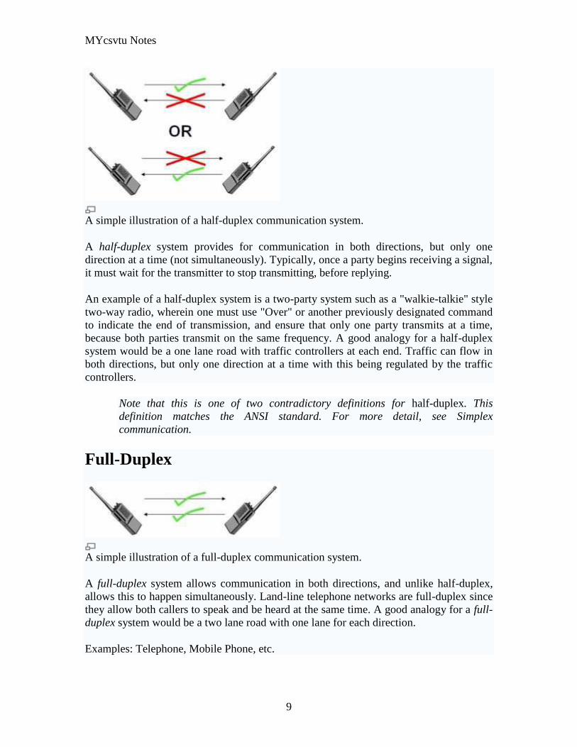
MYcsvtu Notes
9
A simple illustration of a half-duplex communication system
A half-duplex system provides for communication in both directions but only one
direction at a time (not simultaneously) Typically once a party begins receiving a signal
it must wait for the transmitter to stop transmitting before replying
An example of a half-duplex system is a two-party system such as a walkie-talkie style
two-way radio wherein one must use Over or another previously designated command
to indicate the end of transmission and ensure that only one party transmits at a time
because both parties transmit on the same frequency A good analogy for a half-duplex
system would be a one lane road with traffic controllers at each end Traffic can flow in
both directions but only one direction at a time with this being regulated by the traffic
controllers
Note that this is one of two contradictory definitions for half-duplex This
definition matches the ANSI standard For more detail see Simplex
communication
Full-Duplex
A simple illustration of a full-duplex communication system
A full-duplex system allows communication in both directions and unlike half-duplex
allows this to happen simultaneously Land-line telephone networks are full-duplex since
they allow both callers to speak and be heard at the same time A good analogy for a full-
duplex system would be a two lane road with one lane for each direction
Examples Telephone Mobile Phone etc
MYcsvtu Notes
10
Two way radios can be for instance designed as full-duplex systems which transmit on
one frequency and receive on a different frequency This is also called frequency-division
duplex Frequency-division-duplex systems can be extended to farther distances using
pairs of simple repeater stations owing to the fact the communications transmitted on any
one frequency always travels in the same direction
Full-duplex Ethernet connections work by making simultaneous use of all four physical
pair of twisted cable (which are inside the insulation) where two pair are used for
receiving packets and two pair are using for sending packets to a directly connected
device This effectively makes the cable itself a collision-free environment and
theoretically doubles the maximum bandwidth that can be supported by the connection
Channel Characteristics
A communications channel may be described in terms of its characteristic properties
These channel characteristics includebandwidth (how much information can be
conveyed across the channel in a unit of time commonly expressed in bits per second or
bps7 ) quality (how reliably can the information be correctly conveyed across the
channel commonly in terms of bit error rate or BER8 ) and whether the channel is
dedicated (to a single source) or shared (by multiple sources)
Obviously a higher bandwidth is usually a good thing in a channel because it allows more
information to be conveyed per unit of time High bandwidths mean that more users can
share the channel depending on their means of accessing it High bandwidths also allow
more demanding applications (such as graphics) to be supported for each user of the
channel
The capability of a channel to be shared depends of course on the medium used A shared
channel could be likened to a school classroom where multiple students might attempt to
simultaneously catch the teachers attention by raising their hand the teacher must then
arbitrate between these conflicting requests allowing only one student to speak at a time
Reliability of communication is obviously important A low quality channel is prone to
distorting the messages it conveys a high quality channel preserves the integrity of the
messages it conveys Depending on the quality of the channel in use between
communicating entities the probability of the destination correctly receiving the message
from the source might be either very high or very low If the message is received
incorrectly it needs to be retransmitted
If the probability of receiving a message correctly across a channel is too low the system
(source channel message destination) must include mechanisms which overcome the
errors introduced by the low quality channel Otherwise no useful communication is
possible over that channel These mechanisms are embodied in the communication
protocols employed by the corresponding entities
MYcsvtu Notes
11
The effective bandwidth describes what an application experiences and depends on the
quality of service (QOS) provided by the channel For example modems scale back their
transmission speed based largely on their perception of channel quality in order to
optimally use the transmission medium
In general shared and reliable channels are more resource efficient than those which
enjoy neither of these characteristics Shared channels enjoy greater efficiency than
dedicated ones because most data communication is bursty in nature with long idle
periods punctuated by brief message transmissions Reliable channels are more efficient
than unreliable ones because retransmissions are not required as often (because there are
fewer transmission-induced errors)
The OSI Reference Model
The Open Systems Interconnect (OSI) reference model is commonly used to describe in
an abstract manner the functions involved in data communication This model originally
conceived in the International Organization for Standardization (ISO) defines data
communications functions in terms of layers
In the OSI reference model each layer is responsible for certain basic functions such as
getting data from one device to another or from one application on a computer to another
The functions at each layer both depend and build on the functions-called services-
provided by the layers below it Communication between peer entities at a given layer is
done via one or more protocols this communication is invoked via the interface with the
layer below
The OSI reference model is depicted in Table 01 Successful communication between
two applications depends on successful functions at all seven layers In terms of
implementation it is possible for some layers to be trivial in the end what is required
depends on the needs of the applications (and people) engaged in communication
Table 01 OSI Reference Model
Layer Title
7 Application
Higher Layers 6 Presentation
5 Session
4 Transport
MYcsvtu Notes
12
3 Network
Lower Layers 2 Data Link
1 Physical
We must emphasize that the definition of a layered data communication architecture is
only an abstraction The intent of this definition is to unambiguously describe the
functions involved in data communication in a way which allows different systems to be
compared The OSI reference model definition is intended to neither imply nor constrain
the implementation of any communication system
Although various companies and standards bodies have created different layered
communications models the OSI reference model remains the universally-accepted
common denominator for abstract definition Other models define the layer functions
somewhat differently and often have fewer than seven layers In some cases constituent
protocols were specified before the abstract models defining the end-to-end
communication
We will now review the functions of the OSI layers and some of the primary protocols at
each layer9
Layer 1 - The Physical Layer
The physical layer functions include all physical aspects of communicating between two
directly-connected physical entities Typically these physical properties include
electromechanical characteristics of the medium or link between the communicating
physical entities such as connectors voltages transmission frequencies etc This layer
summarizes the physics which underlie the communication path
The essential service provided by the physical layer consists of an unstructured bit
stream which can be used by higher layers to provide the basis for higher layer
communication services An example of a physical layer is the ink on paper used by this
book to convey information Another example is the radio frequencies used in a wireless
communications system
Layer 2 - The Data Link Layer
The data link layer accepts the unstructured bit stream provided by the physical layer and
provides reliable transfer of data between two directly-connected Layer 2 entities
Directly-connected means that the Layer 2 entities communication path does not
require another Layer 2 entity However this does not imply a dedicated path in the case
MYcsvtu Notes
13
of Ethernet many Layer 2 entities can be sharing a common (physical) medium such as a
coaxial cable or a 10BASE-T hub
Layer 2 functionality is limited in scope-delivery of messages over a local area It could
be likened to an intra-office correspondence between co-workers there is a need for
reliability but addressing is relatively simple Local area networks (LANs) operate at
Layer 2
The data link layer is itself conceptually subdivided into two sublayers-medium access
control and logical link control-which more specifically define the primary aspects of
data link layer functionality However this conceptual partitioning by the IEEE 802
committee is somewhat arbitrary and subject to debate
The MAC Sublayer
The medium access control (MAC) sublayer is closely associated with the physical layer
and defines the means by which the physical channel (medium) may be accessed It
coordinates the attempts to seize a shared channel by multiple MAC entities much as a
school teacher must arbitrate between pupils conflicting desires to speak The MAC layer
commonly provides a limited form of error control especially for any header information
which defines the MAC-level destination and higher-layer access mechanism
Ethernet (IEEE 8023) is a prime example of a shared medium with a defined MAC
sublayer functionality The shared medium in Ethernet has traditionally consisted of a
coaxial cable into which multiple entities were tapped as depicted in Figure 05
Although this topology still applies conceptually a hub and spoke medium is now
typically used in which the earlier coaxial cable has been physically collapsed into a hub
device
Figure 05 Ethernet MAC System
11
As a contention medium Ethernet defines how devices sense a channel for its
availability wait when it is busy seize the channel when it becomes available and back-
off for a random length of time following a collision with another simultaneously
MYcsvtu Notes
14
transmitting device On a shared channel such as Ethernet only a single entity can
transmit at a time or messages will be garbled
Not all shared channels involve contention A prime example of a contentionless shared
medium is token ring (IEEE 8025) in which control of the channel is rotated between
the devices sharing the channel in a deterministic round-robin manner Conceptually
control of the channel is given to the entity currently possessing a token If the device
has nothing to transmit it passes the token to the next device attached to the topological
ring depicted in Figure 06
Figure 06 Token Ring MAC System
11
IEEE-defined MAC sublayer addresses are six bytes long and permanently assigned to
each device typically called a network interface card orNIC The IEEE administers the
assignment of these addresses in blocks to manufacturers to assure the global uniqueness
that the MAC sublayer protocols rely on for plug Ocircn play network setup Each
manufacturer must assure individual device identifier uniqueness within their assigned
block
The LLC Sublayer
The logical link control (LLC) sublayer is responsible for reliable transfer of messages-
called frames or more formally link protocol data units (LPDUs)-between two directly-
connected Layer 2 entities Functions needed to support this reliable transfer include
framing (indicating where a Layer 2 message begins and ends) sequence control error
control and flow control
MYcsvtu Notes
15
The degree to which sequence error and flow control are provided by the LLC sublayer
is determined by whether the link protocol is connection-oriented or connectionless A
connectionless link protocol provides little if any support for these functions A
connection-oriented link might use a windowing technique for these functions in which
frames are individually numbered and acknowledged by their sequence number with
only a few such frames outstanding at any time
The connection-oriented functions of sequencing error and flow control provide a
foundation for services provided by higher layers As mentioned earlier not all layer or
sublayer functions are explicitly designed or implemented in any given system Provision
of these functions depends on the services required by higher layers
If the connection-oriented functions of the LLC sublayer are not implemented they must
be performed by higher layers for reliable end-to-end communication If these functions
are provided by several layers they might be somewhat redundant and add unnecessary
overhead (inefficiency) to the system In the worst case redundant provision of these
functions at multiple layers could serve cross purposes and actually degrade overall
system performance
An example of a connectionless LLC protocol is frame relay (T1617 618) which
defines point-to-point links with switches connecting individual links in a mesh topology
In a frame relay network endpoints are connected by a series of links and switches
Because frame relay is defined in terms of the links between frame relay access devices
(FRADs) and switches and between switches themselves it is an LLC protocol
Connectionless Layer 2 protocols are best suited for high quality transmission media
With high quality transmission media errors are rarely introduced in the transmission
between network layer entities and discovery of and recovery from errors is most
efficiently handled by the communicating hosts In this case it is better to move the
packets quickly across the traversed subnetworks from source to destination rather than
checking for errors at Layer 2
Frame relay is derived from the X25 (ISO 8208) protocol which spans Layers 2 and 3
X25 is a connection-oriented packet-switching technology which defines how
neighboring packet switches exchange data with one another in a reliable manner from
end-to-end Frame relay simply removes the connection-oriented functions of error and
sequence control however congestion control functions are provided in frame relay to
prevent the total traffic seen at any point in the network from overwhelming it
Connection-oriented Layer 2 protocols are best suited for low quality transmission media
where it is more efficient and cost-effective to discover and recover from errors as they
occur on each hop than to rely on the communicating hosts to perform error recovery
functions With ever-increasing quality of transmission facilities and decreasing costs of
computation capability at hosts the need for connection-oriented network layer protocols
is diminishing However X25 remains popular outside of North America where it has
been tariffed at levels which encourage its use
MYcsvtu Notes
16
End-to-end communications may be via shared or dedicated facilities or circuits Shared
facilities involve the use of packet switching technology to carry messages from end-to-
end messages are subdivided as necessary into packets which share physical and logical
channels with packets from various sources to various destinations Packet switching is
almost universally used in data communications because it is more efficient for the bursty
nature of data traffic
On the other hand some applications require dedicated facilities from end-to-end because
they are isochronous (eg voice) or bandwidth-intensive (eg large file transfer) This
mode of end-to-end circuit dedication is called circuit switched communication Because
the facilities are dedicated to a single user this tends to be much more expensive than the
packet switched mode of communication But some applications need it-it is an economic
trade-off
Dedicated circuits are a rather extreme form of connection-oriented protocol requiring
the same setup and tear-down phases prior to and following communication If the circuit
setup and tear-down is statically arranged (ie out-of-band) it is referred to as a
permanent virtual circuit or PVC If the circuit is dynamically setup and torn-down in-
band it is referred to as a switched virtual circuit or SVC
Layer 3 - The Network Layer
The network layer defines the functions necessary to support data communication
between indirectly-connected entities It provides the capability of forwarding messages
from one Layer 3 entity to another until the final destination is reached
The network layer introduces another layer of abstraction to the data communications
model It moves messages-called packets or more formally network protocol data units
(NPDUs)-between communicating Layer 3 entities-called end systems nodes or hosts
Network layer functions include route determination or routing and forwarding of
packets to their final destinations
In order to forward a packet to its destination host routing information must be provided
to theintermediate systems (ISs) or routers responsible for forwarding packets to their
respective destinations This routing information includes the address of the destination
which is contained in each packet The next hop to be traversed by the packet is
determined primarily by this destination address We will talk more about addressing and
routing in Chapter 1
This packet forwarding and routing is accomplished independent of both the media and
transmission types used at any step along the way The unimportance of local topology to
the network layer is demonstrated by the common use of cloud diagrams to depict
networks as in Figure 07 Since the network layer is concerned with getting packets
across many local networks called subnetworks its title would be more accurate if it
were the Internetwork Layer
MYcsvtu Notes
17
Figure 07 Network Layer ``Cloud
Diagram
11
The network layer functionality is global in scope-delivery of messages over a wide area
It could be likened to the postal system in which correspondence is passed from location
to location until it eventually reaches the destination address on the envelope10
The
network layer is the domain of wide area networks (WANs)
In order for routers to know how (ie on which link) to forward packets they must have
some knowledge of network topology This knowledge may be complete or partial and is
dynamically created and maintained via routing protocols used by routers to share their
knowledge of network topology with each other Routing is essentially the reduction of
global internetwork topology to local hop-by-hop routing decisions made
independently by each router
As with Layer 2 Layer 3 protocols may be connection-oriented or connectionless A
connection-oriented Layer 3 protocol such as X25 (ISO 8208) operates more statically
The basic idea is that an end-to-end route (X25 virtual connection) is established from
the originating data terminal equipment (DTE) to data communications equipment
(DCE) from DCE to DCE through the network then from the last DCE to the
terminating DTE this is the call setup Packets are then transmitted via this prearranged
route with all packets following the same path through the network Finally the route is
torn down (release) and packets cease flowing
X25 operation is like a phone call because it is a phone call X25 Layer 3 operation
assumes that a reliable connection-oriented service is provided by Layer 2 (also defined
by the X25 standard) although it does provide flow control via sequence numbers
Connectionless Layer 3 protocols such as the ever popular internet protocol (IP)(RFC11
791 and 792) and its ISO counterpart connectionless network protocol (CLNP) (ISO
MYcsvtu Notes
18
8473) route packets dynamically There is no prearranged path which is followed by
subsequent packets flowing from one host to another Instead each packet is individually
routed through a routing mesh there is no reason to believe that sequential packets
flowing between hosts will follow the same path So sequence errors may be introduced
at Layer 3 which must be corrected by a higher layer entity
Connectionless data packets are commonly referred to as datagrams and the service
provided by connectionless Layer 3 protocols is referred to as datagram service Stateless
datagram service is simpler for Layer 3 entities than connection-oriented network layer
services Because there is no state information to maintain dynamic routing protocols can
be used If a router fails during the dialogue between two communicating hosts
neighboring routers will discover this via the routing protocols and find alternate routes
which bypass the failed router
There seems to be a fair amount of ambiguity between the network layer and the LLC
sublayer Both can provide connection-oriented or connectionless services to higher
layers To a large extent if Layer 3 is explicitly implemented there is no need for an
LLC sublayer The primary difference is in scope-LLC addresses and protocols are
oriented toward a more local environment whereas network layer addresses and protocols
are global in scope
Excellent references to routing and forwarding of data packets can be found in [PERL92]
and [STEN95]
Layer 4 - The Transport Layer
The transport layer is concerned with getting Layer 4 messages-called segments or more
formally transport protocol data units (TPDUs) -from source to destination in a reliable
manner The perspective of Layer 4 is of end-to-end communications rather than the hop-
by-hop perspective of Layer 3 Layer 4 assumes that packets can be moved from network
entity to network entity eventually getting to the final destination host How this is
accomplished is of no concern to Layer 4 functionality
Like other layers transport layer protocols can be either connection-oriented or
connectionless depending on the services required by higher layers A common
implementation of Layers 3 and 4 involves a connection-oriented transport layer protocol
running over a connectionless network layer protocol such as the ubiquitous TCPIP
protocol suite In this instance the communicating hosts maintain state information on
communications with each other to determine when and what to send This state
information defines the connection between the communicating Layer 4 entities
The general idea here is that two communicating hosts need not be concerned with the
topology of the internetwork which lies between them They only need to know the state
of their pairwise communication If part of the intervening internetwork cloud suffers a
failure the Layer 3 entities (routers) will deal with it and recover dynamically Aside
MYcsvtu Notes
19
from potential retransmission of any lost segments the hosts Layer 4 entries do not have
to be at all concerned with routing and recovery activities at Layer 3
In the IP protocol suite the primary connectionless Layer 4 protocol is the User
Datagram Protocol (UDP)(RFC 768) which is carried by IP the primary connection-
oriented protocol is the Transmission Control Protocol (TCP)(RFC 793) The ISO world
defines five classes of transport layer protocol beginning with Class 0 (TP-0) for
connectionless operation and range up to Class 4 (TP-4)(ISO 8073) for connection-
oriented operation
Layer 5 - The Session Layer
The session layer provides a control structure for communication between applications
on hosts The communication at layer 5 is called a session which defines the relative
timing of communications between the hosts applications Synchronization of
communicating applications comes into play when coordinated timing of corresponding
events at the endpoints is imperative such as in financial transactions
Remember layers define communication functions not implementations It is unlikely
that a session layer would be explicitly implemented as a stand-alone program although
its functions would be implemented somewhere Session layer functions depend on the
reliability of communications between the endpoints and session layer functions must
therefore be implemented above Layer 4
Layer 6 - The Presentation Layer
The presentation layer performs any necessary data transformations or formatting
required by the end applications Functions provided by the presentation layer include
data compression file formatting and encryption Common data formatting is important
because it allows the same application file to be accessed by the application running on
different computer platforms This book is itself the product of an application running on
different platforms with common files being modified via these different platforms
Abstract Syntax Notation (ASN1) is commonly used to specify data values in a way
which allows processors to communicate independent of their varying native integer
sizes bit orderings (big or little endian) character sets etc ASN1 is a transfer syntax a
presentation layer formatting which appears frequently in the CDPD specification for
unambiguous definition of network management accounting limited size messaging and
other functions
An example of ASN1 encoding from an accounting Traffic Matrix Segment in the
CDPD specification is the following
MYcsvtu Notes
20
TrafficType = INTEGER
registration (0)
deregistration (1)
ip(2)
clnp(3)
Layer 7 - The Application Layer
The application layer provides the services which directly support an application running
on a host These services are directly accessible by an application via common well-
known application program interfaces (APIs) which can actually occur at many layers
Examples of layer 7 services include FTP (file transfer protocol) Telnet and SNMP
(simple network management protocol) Most network management activities are based
on the services provided by layer 7 application entities which in turn rely on lower layer
services to be able to perform their functions
7 Application ECHO ENRP FTP Gopher HTTP NFS RTSP SIP SMTP SNMP
SSH Telnet Whois XMPP
6 Presentation XDR ASN1 SMB AFP NCP
5 Session ASAP TLS SSL ISO 8327 CCITT X225 RPC NetBIOS ASP
4 Transport TCP UDP RTP SCTP SPX ATP IL
3 Network IP ICMP IGMP IPX OSPF RIP IGRP EIGRP ARP RARP X25
2 Data Link Ethernet Token ring HDLC Frame relay ISDN ATM 80211 WiFi
FDDI PPP
1 Physical 10BASE-T 100BASE-T 1000BASE-T SONETSDH G709 T-
carrierE-carrier various 80211 physical layers
The TCPIP Reference Model
The TCPIP reference model is the network model used in the current Internet
architecture [19] It has its origins back in the 1960s with the grandfather of the Internet
the ARPANET This was a research network sponsored by the Department of Defense in
the United States The following were seen as major design goals
ability to connect multiple networks together seamlessly
ability for connections to remain intact as long as the source and destination
machines were functioning
MYcsvtu Notes
21
to be built on flexible architecture
The reference model was named after two of its main protocols TCP (Transmission
Control Protocol) [12] and IP (Internet Protocol)
They choose to build a packet-switched network based on a connectionless internetwork
layer
Figure 21 TCPIP Network Protocol
A detailed description of the reference model is beyond the scope of this document and
project The basic idea of the networking system is to allow one application on a host
computer to talk to another application on a different host computer
The application forms its request then passes the packet down to the lower layers which
add their own control information either a header or a footer onto the packet Finally the
packet reaches the physical layer and is transmitted through the cable onto the destination
host The packet then travels up through the different layers with each layer reading
deciphering and removing the header or footer that was attached by its counterpart on the
originating computer Finally the packet arrives at the application it was destined for
Even though technically each layer communicates with the layer above or below it the
process can be viewed as one layer talking to its partner on the host as figure 21 shows
The Host-to-Network Layer
The Host-to-Network layer interfaces the TCPIP protocol stack to the physical network
The TCPIP reference model does not specify in any great detail the operation of this
layer except that the host has to connect to the network using some protocol so it can
send IP packets over it
As it is not officially defined it varies from implementation to implementation with
vendors supplying their own version
MYcsvtu Notes
22
The Network Layer
The job of the network layer is to inject packets into any network and have them travel
independently to the destination The layer defines IP (Internet Protocol) for its official
packet format and protocol Packet routing is a major job of this protocol
The Transport Layer
The transport layer is the interface between the application layer and the complex
hardware of the network It is designed to allow peer entities on the source and
destination hosts to carry on conversations
Data may be user data or control data Two modes are available full-duplex and half
duplex In full-duplex operation both sides can transmit and receive data simultaneously
whereas in half duplex a side can only send or receive at one time
Interaction between the transport layer and the layers immediately above and below are
shown in figure 22 Any program running in the application layer has the ability to send
a message using TCP or UDP which are the two protocols defined for the transport layer
The application can communicate with the TCP or the UDP service whichever it
requires Both the TCP and UDP communicate with the Internet Protocol in the internet
layer In all cases communication is a two way process The applications can read and
write to the transport layer The diagram only shows two protocols in the transport layer
TTCP will also reside in this layer between the other two protocols and function in the
same manner
Figure 22 Interaction with Application Transport and Internet Layers
A message to be sent originates in the application layer This is then passed down onto
the appropriate protocol in the transport layer These protocols add a header to the
message for the corresponding transport layer in the destination machine for purposes of
reassembling the message The segment is then passed onto the internet layer where the
Internet Protocol adds a further header Finally the segment is passed onto the physical
MYcsvtu Notes
23
layer a header and a trailer are added at this stage Figure 23 shows the structure of the
final segment being sent
Figure 23 Transmitted Segment from TCPIP Network
The Application Layer
The original TCPIP specification described a number of different applications that fit
into the top layer of the protocol stack These applications include Telnet FTP SMTP
and DNS
Telnet is a program that supports the TELNET [13] protocol over TCP TELNET is a
general two-way communication protocol that can be used to connect to another host and
run applications on that host remotely
FTP (File Transfer Protocol) [14] is a protocol that was originally designed to promote
the sharing of files among computer users It shields the user from the variations of file
storage on different architectures and allows for a reliable and efficient transfer of data
SMTP (Simple Mail Transport Protocol) [15] is the protocol used to transport electronic
mail from one computer to another through a series of other computers along the route
DNS [10] (Domain Name System) resolves the numerical address of a network node into
its textual name or vice-versa It would translate wwwyahoocom to 2047117771 to
allow the routing protocols to find the host that the packet is destined for
What is a Topology
The physical topology of a network refers to the configuration of cables computers and
other peripherals Physical topology should not be confused with logical topology which
is the method used to pass information between workstations Logical topology was
discussed in the Protocol chapter
Main Types of Physical Topologies
The following sections discuss the physical topologies used in networks and other related
topics
Linear Bus
MYcsvtu Notes
24
Star
Star-Wired Ring
Tree
Considerations When Choosing a Topology
Summary Chart
Linear Bus
A linear bus topology consists of a main run of cable with a terminator at each end (See
fig 1) All nodes (file server workstations and peripherals) are connected to the linear
cable Ethernet and LocalTalk networks use a linear bus topology
Fig 1 Linear Bus topology
Advantages of a Linear Bus Topology
Easy to connect a computer or peripheral to a linear bus
Requires less cable length than a star topology
Disadvantages of a Linear Bus Topology
Entire network shuts down if there is a break in the main cable
Terminators are required at both ends of the backbone cable
Difficult to identify the problem if the entire network shuts down
Not meant to be used as a stand-alone solution in a large building
Star
A star topology is designed with each node (file server workstations and peripherals)
connected directly to a central network hub or concentrator (See fig 2)
Data on a star network passes through the hub or concentrator before continuing to its
destination The hub or concentrator manages and controls all functions of the network It
also acts as a repeater for the data flow This configuration is common with twisted pair
cable however it can also be used with coaxial cable or fiber optic cable
MYcsvtu Notes
25
Fig 2 Star topology
Advantages of a Star Topology
Easy to install and wire
No disruptions to the network then connecting or removing devices
Easy to detect faults and to remove parts
Disadvantages of a Star Topology
Requires more cable length than a linear topology
If the hub or concentrator fails nodes attached are disabled
More expensive than linear bus topologies because of the cost of the
concentrators
The protocols used with star configurations are usually Ethernet or LocalTalk Token
Ring uses a similar topology called the star-wired ring
Star-Wired Ring
A star-wired ring topology may appear (externally) to be the same as a star topology
Internally the MAU (multistation access unit) of a star-wired ring contains wiring that
allows information to pass from one device to another in a circle or ring (See fig 3) The
Token Ring protocol uses a star-wired ring topology
Tree
A tree topology combines characteristics of linear bus and star topologies It consists of
groups of star-configured workstations connected to a linear bus backbone cable (See fig
MYcsvtu Notes
26
4) Tree topologies allow for the expansion of an existing network and enable schools to
configure a network to meet their needs
Fig 4 Tree topology
Advantages of a Tree Topology
Point-to-point wiring for individual segments
Supported by several hardware and software venders
Disadvantages of a Tree Topology
Overall length of each segment is limited by the type of cabling used
If the backbone line breaks the entire segment goes down
More difficult to configure and wire than other topologies
5-4-3 Rule
A consideration in setting up a tree topology using Ethernet protocol is the 5-4-3 rule
One aspect of the Ethernet protocol requires that a signal sent out on the network cable
reach every part of the network within a specified length of time Each concentrator or
repeater that a signal goes through adds a small amount of time This leads to the rule that
between any two nodes on the network there can only be a maximum of 5 segments
connected through 4 repeatersconcentrators In addition only 3 of the segments may be
populated (trunk) segments if they are made of coaxial cable A populated segment is one
which has one or more nodes attached to it In Figure 4 the 5-4-3 rule is adhered to The
MYcsvtu Notes
27
furthest two nodes on the network have 4 segments and 3 repeatersconcentrators
between them
This rule does not apply to other network protocols or Ethernet networks where all fiber
optic cabling or a combination of a fiber backbone with UTP cabling is used If there is a
combination of fiber optic backbone and UTP cabling the rule is simply translated to 7-
6-5 rule
] Mesh
Full
Fully Connected The type of network topology in which each of the nodes of the network is
connected to each of the other nodes in the network with a point-to-point link ndash
this makes it possible for data to be simultaneously transmitted from any single
node to all of the other nodes
Note The physical fully connected mesh topology is generally too costly and
complex for practical networks although the topology is used when there are only
a small number of nodes to be interconnected[3]
Partial
Partially Connected The type of network topology in which some of the nodes of the network are
connected to more than one other node in the network with a point-to-point link ndash
this makes it possible to take advantage of some of the redundancy that is
provided by a physical fully connected mesh topology without the expense and
complexity required for a connection between every node in the network
Note In most practical networks that are based upon the physical partially
connected mesh topology all of the data that is transmitted between nodes in the
network takes the shortest path between nodes except in the case of a failure or
break in one of the links in which case the data takes an alternate path to the
destination ndash this implies that the nodes of the network possess some type of
logical routing algorithm to determine the correct path to use at any particular
time
[edit] Hybrid Network Topologies
The hybrid topology is a type of network topology that is composed of one or more
interconnections of two or more networks that are based upon different physical
topologies or a type of network topology that is composed of one or more
interconnections of two or more networks that are based upon the same physical
topology but where the physical topology of the network resulting from such an
interconnection does not meet the definition of the original physical topology of the
interconnected networks (eg the physical topology of a network that would result from
an interconnection of two or more networks that are based upon the physical star
topology might create a hybrid topology which resembles a mixture of the physical star
MYcsvtu Notes
28
and physical bus topologies or a mixture of the physical star and the physical tree
topologies depending upon how the individual networks are interconnected while the
physical topology of a network that would result from an interconnection of two or more
networks that are based upon the physical distributed bus network retains the topology of
a physical distributed bus network)
Star-Bus A type of network topology in which the central nodes of one or more individual
networks that are based upon the physical star topology are connected together
using a common bus network whose physical topology is based upon the
physical linear bus topology the endpoints of the common bus being terminated
with the characteristic impedance of the transmission medium where required ndash
eg two or more hubs connected to a common backbone with drop cables
through the port on the hub that is provided for that purpose (eg a properly
configured uplink port) would comprise the physical bus portion of the physical
star-bus topology while each of the individual hubs combined with the
individual nodes which are connected to them would comprise the physical star
portion of the physical star-bus topology
Star-of-Stars
Hierarchical Star A type of network topology that is composed of an interconnection of individual
networks that are based upon the physical star topology connected together in a
hierarchical fashion to form a more complex network ndash eg a top level central
node which is the hub of the top level physical star topology and to which other
second level central nodes are attached as the spoke nodes each of which in
turn may also become the central nodes of a third level physical star topology
Notes 1) The physical hierarchical star topology is not a combination of the physical
linear bus and the physical star topologies as cited in some texts as there is no
common linear bus within the topology although the top level hub which is the
beginning of the physical hierarchical star topology may be connected to the
backbone of another network such as a common carrier which is topologically
not considered to be a part of the local network ndash if the top level central node is
connected to a backbone that is considered to be a part of the local network then
the resulting network topology would be considered to be a hybrid topology that
is a mixture of the topology of the backbone network and the physical hierarchical
star topology
2) The physical hierarchical star topology is also sometimes incorrectly referred
to as a physical tree topology since its physical topology is hierarchical however
the physical hierarchical star topology does not have a structure that is determined
by a branching factor as is the case with the physical tree topology and therefore
nodes may be added to or removed from any node that is the hub of one of the
individual physical star topology networks within a network that is based upon the
physical hierarchical star topology
3) The physical hierarchical star topology is commonly used in outside plant
(OSP) cabling to connect various buildings to a central connection facility which
MYcsvtu Notes
29
may also house the demarcation point for the connection to the data transmission
facilities of a common carrier and in inside plant (ISP) cabling to connect
multiple wiring closets within a building to a common wiring closet within the
same building which is also generally where the main backbone or trunk that
connects to a larger network if any enters the building
Star-wired Ring A type of hybrid physical network topology that is a combination of the physical
star topology and the physical ring topology the physical star portion of the
topology consisting of a network in which each of the nodes of which the network
is composed are connected to a central node with a point-to-point link in a hub
and spoke fashion the central node being the hub and the nodes that are
attached to the central node being the spokes (eg a collection of point-to-point
links from the peripheral nodes that converge at a central node) in a fashion that is
identical to the physical star topology while the physical ring portion of the
topology consists of circuitry within the central node which routes the signals on
the network to each of the connected nodes sequentially in a circular fashion
Note In an 8025 Token Ring network the central node is called a Multistation
Access Unit (MAU)
Hybrid Mesh A type of hybrid physical network topology that is a combination of the physical
partially connected topology and one or more other physical topologies the mesh
portion of the topology consisting of redundant or alternate connections between
some of the nodes in the network ndash the physical hybrid mesh topology is
commonly used in networks which require a high degree of availability
Considerations When Choosing a Topology
Money A linear bus network may be the least expensive way to install a network
you do not have to purchase concentrators
Length of cable needed The linear bus network uses shorter lengths of cable
Future growth With a star topology expanding a network is easily done by
adding another concentrator
Cable type The most common cable in schools is unshielded twisted pair which
is most often used with star topologies
Summary Chart
Common Cable Common Protocol
Linear Bus Twisted Pair
Coaxial
Ethernet
LocalTalk
MYcsvtu Notes
30
Fiber
Star Twisted Pair
Fiber
Ethernet
LocalTalk
Star-Wired Ring Twisted Pair Token Ring
Tree
Twisted Pair
Coaxial
Fiber
Ethernet
Internet vs Web
The Internet and the World Wide Web are not synonymous the Internet is a collection of
interconnected computer networks linked by copper wires fiber-optic cables wireless
connections etc the Web is a collection of interconnected documents and other
resources linked by hyperlinks and URLs The World Wide Web is accessible via the
Internet as are many other services including e-mail file sharing and others described
below
The best way to define and distinguish between these terms is to understand the Internet
protocol suite This collection of protocols is organized into layers such that each layer
provides the foundation and the services required by the layer above In this conception
the term Internet refers to computer networks that all communicate with IP (Internet
protocol) and TCP (transfer control protocol) Once this networking structure is
established then other protocols can run ―on top These other protocols are sometimes
called services or applications Hypertext transfer protocol or HTTP is an application
layer protocol that links billions of files together into the World Wide Web
Common uses of the Internet
The World Wide Web
Through keyword-driven Internet research using search engines like Google
millions worldwide have easy instant access to a vast and diverse amount of
online information Compared to encyclopedias and traditional libraries the
World Wide Web has enabled a sudden and extreme decentralization of
information and data
Many individuals and some companies and groups have adopted the use of Web logs or
blogs which are largely used as easily-updatable online diaries Some commercial
organizations encourage staff to fill them with advice on their areas of specialization in
the hope that visitors will be impressed by the expert knowledge and free information
and be attracted to the corporation as a result One example of this practice is Microsoft
MYcsvtu Notes
31
whose product developers publish their personal blogs in order to pique the publics
interest in their work
For more information on the distinction between the World Wide Web and the Internet
itself mdash as in everyday use the two are sometimes confused mdash see Dark internet where
this is discussed in more detail
Remote access
The Internet allows computer users to connect to other computers and information stores
easily wherever they may be across the world They may do this with or without the use
of security authentication and encryption technologies depending on the requirements
This is encouraging new ways of working from home collaboration and information
sharing in many industries An accountant sitting at home can audit the books of a
company based in another country on a server situated in a third country that is remotely
maintained by IT specialists in a fourth These accounts could have been created by
home-working book-keepers in other remote locations based on information e-mailed to
them from offices all over the world Some of these things were possible before the
widespread use of the Internet but the cost of private leased lines would have made
many of them infeasible in practice
An office worker away from his desk perhaps the other side of the world on a business
trip or a holiday can open a remote desktop session into his normal office PC using a
secure Virtual Private Network (VPN) connection via the Internet This gives him
complete access to all his normal files and data including e-mail and other applications
while he is away
This concept is also referred to by some network security people as the Virtual Private
Nightmare because it extends the secure perimeter of a corporate network into its
employees homes this has been the source of some notable security breaches but also
provides security for the workers
Functions
File-sharing
Instant messaging
Internet fax
Search engine
World Wide Web
MYcsvtu Notes
32
Intranets
What are Intranets
bull Intranet is Intra+ Net so an Intranet is an internal or private Internet used strictly
within the confines of a company university or organization Inter means
between or among hence the difference between the Internet and an Intranet
Some formal definitions of Intranets
bull Brown amp Duguid ―Intranets help present and
circulate boundary objects
bull Choo Detlor amp Turnbull ―Intranetshellip support the creation sharing and use of
knowledge
bull Stenmark ―Intranets are organizationally
restricted
A technical definition
bull An Intranet is a network based on the internet TCPIP open standard An intranet
belongs to an organization and is designed to be accessible only by the
organizations members employees or others with authorization An intranets
Web site looks and act just like other Web sites but has a firewall surrounding it
to fend off unauthorized users
Design Of Intranets
Steps
bull Analyze the organizationlsquos information ecology
bull Identify the typical problems experienced by users
bull Analyze the information behaviors of these set of users
bull Create value added processes to resolve the problems of users and to improve the
Information Ecology
Value Added Processes
bull Intranets may be designed to improve the organizational information ecology
MYcsvtu Notes
33
bull Intranets provide a unified information space in which users can communicate
and collaborate with others
bull intranet applications and services may add value by supporting the organizationlsquos
knowledge creating and decision making process
Two Models of Online Environments
Centralized
Distributed
Centralized Environments
bull Before the web the centralized model was all we had (examples include
CompuServe Prodigy)
bull On the web centralized models include site-based services such as Yahoo
bull Most (all) college and university services are offered using the centralized
model
MYcsvtu Notes
34
bull But centralized environments are static inflexible expensive
Distributed Environments
bull The World Wide Web is an example of a distributed environment
bull Resources access are not centralized but scattered around the world
ndash Resources in the form of a network of connected (via DNS) web servers
ndash Access in the form of a network of connected (via DNS) internet service
providers
ndash Users in the form of individualized and connected (via HTTP) web
browsers
bull The big issue ndash integration ndash that is making different systems work together
Design Principles
Network Design Principles
ndash Specifies how networks differ from traditional learning
ndash The idea is that each principle confers an advantage over non-network
systems
ndash Can be used as a means of evaluating new technology
1 Decentralize
ndash Centralized networks have a characteristic starlsquo shape
bull Some entities have many connections
bull The vast majority have few
bull Eg broadcast network teacher in a classroom
ndash Decentralized networks form a mesh
bull The weight of connections flow is distributed
bull Balanced load = more stable
bull Foster connections between entities fill outlsquo the star
Distribute
ndash Network entities reside in different physical locations
bull Reduces risk of network failure
bull Reduces need for major infrastructure such as powerful servers
large bandwidth massive storage
ndash Examples
bull Peer-to-peer networks such as Kazaa Gnutella
bull Content syndication networks such as RSS
ndash Emphasis is on sharing not copying
bull Locallsquo copies are temporary
MYcsvtu Notes
35
Computer Graphics
Computer Graphics is about animation (films)
Games are very important in Computer Graphics
Medical Imaging is another driving force
Computer Aided Design too
Graphics Definitions
bull Point
ndash a location in space 2D or 3D
ndash sometimes denotes one pixel
bull Line
ndash straight path connecting two points
ndash infinitesimal width consistent density
ndash beginning and end on points
bull Vertex
ndash point in 3D
bull Edge
ndash line in 3D connecting two vertices
bull PolygonFaceFacet
ndash arbitrary shape formed by connected vertices
ndash fundamental unit of 3D computer graphics
bull Raster
ndash derived from TV systems for a row of pixels
ndash commonly referred to as a scanline
ndash does influence algorithms ndash reducing memory requirements parallelism
etc
ndash is the derivation of rasterization scan-line algorithms
Displays
bull Most desktop displays use a cathode ray tube (CRT) while portable computing
devices such as laptops incorporate liquid crystal display (LCD)
bull Because of their slimmer design and smaller energy consumption monitors using
LCD technologies are beginning to replace the venerable CRT on many desktops
Cathode-Ray Tubes
MYcsvtu Notes
36
bull Classical output device is a monitor
bull Cathode-Ray Tube (CRT)
ndash Invented by Karl Ferdinand Braun (1897)
ndash Beam of electrons directed from cathode (-)to phosphor-coated
(fluorescent) screen (anode (+))
ndash Directed by magnetic focusing and deflection coils (anodes) in vacuum
filled tube
ndash Phosphor emits photon of light when hit by an electron of varied
persistence (long 15-20 ms for texts short lt 1ms for animation)
ndash Refresh rate (50-60 Hz 72-76 Hz) to avoid flicker trail
ndash Phosphors are organic compounds characterized by their persistence and
their color (blue red green)
Cathode-Ray Tubes
bull Cathode-Ray Tube (CRT)
ndash Horizontal deflection and vertical deflection direct the electron beam to
any point on the screen
ndash Intensity knob regulates the flow of electrons by controlling the voltage at
the control grid (high voltage reduces the electron density and thus
brightness)
ndash Accelerating voltage from positive coating inside screen (anode screen) or
an accelerating anode
bull Image maintenance
ndash Charge distribution to store picture information
OR
ndash Refresh CRT refreshes the display constantly to maintain phosphor glow
Cathode-Ray Tubes
bullCathode-Ray Tube (CRT)
ndash Horizontal deflection and vertical deflection direct the electron beam to any point
on the screen
ndash Intensity knob regulates the flow of electrons by controlling the voltage at the
control grid (high voltage reduces the electron density and thus brightness)
ndash Accelerating voltage from positive coating inside screen (anode screen) or an
accelerating anode
bullImage maintenance
ndash Charge distribution to store picture information
OR
ndash Refresh CRT refreshes the display constantly to maintain phosphor glow
bull Characteristics of Cathode-Ray Tube (CRT)
MYcsvtu Notes
37
ndash Intensity is proportional to the number of electrons repelled in beam per
second (brightness)
ndash Resolution is the maximum number of points that can be displayed
without overlap is expressed as number of horizontal points by number of
vertical points points are called pixels (picture elements) example
resolution 1024 x 768 pixels Typical resolution is 1280 x 1024 pixels
bull High-definition systems high resolution systems
bull Focusing
ndash Focusing forces the electron beam to converge to a point on the monitor
screen
ndash Can be electrostatic (lens) or magnetic (field)
bull Deflection
ndash Deflection directs the electron beam horizontally andor vertically to any
point on the screen
ndash Can be controlled by electric (deflection plates slide 9) or magnetic fields
(deflection coils slide 5)
ndash Magnetic coils two pairs (topbottom leftright) of tube neck
ndash Electric plates two pairs (horizontal vertical)
Raster-scan Displays
bullVideo displays can be either raster-scan or random-scan displays
bullRaster-scan display is the most common type of monitor using a CRT
bullThe electron beam scans the screen from top to bottom one row at a time Each row is
called a scan line
bullThe electron beam is turned on and off to produce a collection of dots painted one row at
a time These will form the image
bullA raster is a matrix of pixels covering the screen area and is composed of raster lines
Raster-scan Displays
MYcsvtu Notes
38
Raster-scan Displays
bullThe image is stored in a frame buffer containing the total screen area and where each
memory location corresponds to a pixel
bullIn a monochrome system each bit is 1 or 0 for the corresponding pixel to be on or off
(bitmap)
bullThe display processor scans the frame buffer to turn electron beam onoff depending if
the bit is 1 or 0
bullFor color monitors the frame buffer also contains the color of each pixel (color buffer)
as well as other characteristics of the image (gray scale hellip) 8 bitspixel 0255
(pixmap)
bullDepth of the buffer area is the number of bits per pixel (bit planes) up to 24
bullExamples television panels printers PC monitors (99 of raster-scan)
Raster-scan Displays
bullRefresh rate 24 is a minimum to avoid flicker corresponding to 24 Hz (1 Hz = 1 refresh
per second)
bullCurrent raster-scan displays have a refresh rate of at least 60 frames (60 Hz) per second
up to 120 (120 Hz)
bullUses large memory 640x480 307200 bits 38 kB
bullRefresh procedure
MYcsvtu Notes
39
ndashHorizontal retrace ndash beam returns to left of screen
ndashVertical retrace ndash bean returns to top left corner of screen
ndashInterlaced refresh ndash display first even-numbered lines then odd-numbered lines
permits to see the image in half the time
useful for slow refresh rates (30 Hz shows as 60 Hz)
Random-scan Displays
bullRandom scan systems are also called vector stroke-writing or calligraphic displays
bullThe electron beam directly draws the picture in any specified order
bullA pen plotter is an example of such a system
bullPicture is stored in a display list refresh display file vector file or display program as a
set of line drawing commands
bullRefreshes by scanning the list 30 to 60 times per second
bullMore suited for line-drawing applications such as architecture and manufacturing
Random-scan Displays
bullAdvantages
ndashHigh resolution
ndashEasy animation
ndashRequires little memory
bullDisadvantages
ndashRequires intelligent electron beam (processor controlled)
ndashLimited screen density limited to simple line-based images
ndashLimited color capability
bullImproved in the 1960lsquos by the Direct View Storage Tube (DVST) from Tektronix
Color CRT Monitor
Uses different phosphors a combination of Red Green and Blue to produce any color
Two methods
Random scan uses beam penetration
2 layers (Red Green) phosphors low speed electrons excite Red high speed electrons
excite Green interrmediate speed excite both to get yellow and orange Color is
controlled by electron beam voltage
Only produces a restricted set of colors
Raster scan uses a shadow mask with three electron guns Red Green and Blue (RGB
color model) Color is produced by adjusting the intensity level of each electron beam
Produces a wide range of colors from 8 to several millions
Raster scan
Most common as found in televisions
Beam scanned left to right flicked back to rescan from top to bottom then repeated
Repeated at 30Hz per frame sometimes higher to reduce flicker Interlacing scanning
MYcsvtu Notes
40
odd lines in whole screen then even lines is also used to reduce flicker Can also use
high-persistence phosphor to reduce flicker but causes image smearing especially with
significant animation
Resolution typically 512x512 but high-quality screens are available (and becoming more
common) at up to approximately 1600x1200 pixels Sun workstations have screens of
1192x980 pixels
Black amp white screens can display grayscale by varying the intensity of the electron
beam
Colour is achieved using three electron guns which hit red green or blue phosphors
Combining these colours can produce many others including white (all on) Phosphor
dots focused using a shadow mask - makes colour screens lower resolution than
monochrome
Alternative approach beam penetration Special phosphor glows a different colour
depending on intensity of beam
Colour or intensity at pixel held by computerlsquos video card 1 bitpixel can store offon
information hence only black ampwhite More bitspixel give rise to more colour
possibilities eg 8 bitspixel gives rise to 2^8=256 possible colours at any one time
Random Scan (Directed-beam refresh vector display)
Instead of scanning the whole display sequentially and horizontally the random scan
draws the lines to be displayed directly Screen update at gt30Hz to reduce flicker
Jaggies not found and higher resolutions possible (up to 4096x4096 pixels) Colour
achieved using beam penetration generally of poorer quality Eye strain and fatigue still
a problem and vector displays are more expensive
Direct view storage tube (DVST)
Used a lot in analogue storage oscilloscopes
Similar to random scan crt but image maintained by flood guns - no flicker Can be
incrementally updated but not selectively erased image has to be redrawn on completely
erased screen High resolution (typically 4096x3120 pixels) but low contrast low
brightness and difficulty in displaying colour
What is a Multimedia System
bull A system that involves
ndash generation
ndash representation
ndash storage
ndash transmission
ndash search and retrieval
ndash delivery
MYcsvtu Notes
41
of multimedia information
productionauthoring tools
compression and formats
file system design
networking issues
database management
server design streaming
Multimedia System Architecture
Information management subsystem Presentation Query
Storage subsystem Efficiently stored
amp retrieved
Network subsystem Delivery
Adaptation in Multimedia Systems
bull Multimedia systems can profit a lot from personalization
ndash User behavior
ndash User properties
bull Adaptation
ndash Models
ndash Mechanisms
Multimedia in a mobile environment
MYcsvtu Notes
42
bull Applications
ndash Emergency response systems mobile commerce phone service
entertainment games
What is Sound
A ripple is a pressure wave in water created by an object striking the water
Sound is a pressure wave in air created for example by an object such as a string
or our vocal cords vibrating Dark here represents more pressure light represents
less
MYcsvtu Notes
43
Sine Waves Form Pure Tones
This simple sound wave is a Sine Wave a Pure tone produced by a simple vibration
Sine Wave Sample Tone
This can be represented graphically as shown above
Converting Pressure into Voltage
The pressure wave of sound moves a diaphragm in the microphone which produces a
voltage proportional to the pressure of the sound wave at each instant
Animation
MYcsvtu Notes
44
bull Animation is the rapid display of a sequence of images of 2-D artwork or model
positions in order to create an illusion of movement It is an optical illusion of
motion due to the phenomenon of persistence of vision This could be anything
from a flip book to a motion picture film Animation deals with the generation
sequencing and display a set of images which is called frames to create an effect
of visual change or motion similar to a movie film
bull Animation is used in those instance where videography is not possible
Hardware Requirement For Animation
bull Image Generation Tools amp Devices
bull Computer monitors with image display Capability
Software Requirement For Animation
bull Animation creating software
bull Screen Capture Software
bull Animation Clips
bull Software support For High Resolution
bull Recording amp Playback Capability
bull Transition effect
Early animation
There is no single person that can be considered the creator of the art of animation as
there were several people doing several projects which could be considered various types
of animation all around the same time (Short hand-drawn animation scenes could be
presented with the Phenakistoscope the Zoetrope and other optical toys already in the
early 1800s)
The following is a brief listing on those who are often acknowledged as significant to the
development of animation Note that this list is by no means a comprehensive list of
contributors to early animation
Georges Meacuteliegraves was a creator of special effect films such as A Trip to the Moon He
used many techniques ndash one of which was to stop the camera rolling change something
in the scene and then continue rolling the film This is a very similar idea to that of stop-
motion animation Meacuteliegraves accidentally happened upon the technique when his camera
broke down while shooting a bus driving by When the camera was fixed a horse
happened to be passing by just as Meacuteliegraves continued to film The result was that the bus
appeared to change into a horse
MYcsvtu Notes
45
Fantasmagorie by Emile Cohl 1908
Eacutemile Cohl began drawing cartoon strips and created a film in 1908 called
Fantasmagorie The film largely consisted of a stick figure moving about and
encountering all manner of morphing objects such as a wine bottle that transforms into a
flower There were also sections of live action where the animatorlsquos hands would enter
the scene The film was created by drawing each frame on paper and then shooting each
frame onto negative film which gave the picture a blackboard look
Winsor McCay created detailed animations that required a team of artists and painstaking
attention for detail Each frame was drawn on paper requiring backgrounds to be
redrawn as well characters to be animated His films such as Gertie the Dinosaur (1914)
and The Sinking of the Lusitania (1918) were of an impressive scale although The
Sinking of the Lusitania used cels
In 1919 Otto Messmer created the character of Felix the cat for Pat Sullivans animation
studios The importance of Felix lies in the characters strong personality created largely
through gesture and actions
Animation techniques
Animation techniques are incredibly varied and difficult to categorize Techniques are
often related or combined The following is a brief on common types of animation
Again this list is by no means comprehensive
Traditional animation
An example of traditional animation a horse animated by rotoscoping from Edweard
Muybridges 19th century photos
Main article Traditional animation
MYcsvtu Notes
46
Also called cel animation the frames of a traditionally animated movie are hand-drawn
The drawings are traced or copied onto transparent acetate sheets called cels which are
then placed over a painted background and photographed one by one on a rostrum
camera Nowadays the use of cels (and cameras) is mostly obsolete since the drawings
are scanned into computers and digitally transferred directly to 35 mm film The look
of traditional cel animation is still preserved and the character animators work has
remained essentially the same over the past 70 years Because of the digital influence
over modern cel animation it is also known as tradigital animation
Examples The Lion King Spirited Away Les Triplettes de Belleville
Full animation The most common style in animation known for its realistic and often very detailed art
Examples All Disney feature length animated films The Secret of NIMH The Iron Giant
Limited animation A cheaper process of making animated cartoons that does not follow a realistic
approach
Examples The Flintstones Yellow Submarine
Rubber hose The characters are usually cartoony and the animators have a lot of artistic freedom as
rubber hose animations dont have to follow the laws of physics and anatomy in the same
degree as the other main styles in animation
Examples Early Mickey Mouse cartoons Ren and Stimpy Popeye
Rotoscoping A technique where animators trace live action movement frame by frame for use in
animated films
Examples Gullivers Travels American Pop
Stop motion
Stop-motion animation is any type of animation which requires the animator to physically
alter the scene shoot a frame again alter the scene and shoot a frame and so on to create
the animation There are many different types of stop-motion animation some noteable
examples are listed below
Clay animation
MYcsvtu Notes
47
A clay animation scene from a TV commercial
Often abbreviated to claymation this is a type of stop-motion animation using
figures made of clay or a similar malleable material The figures may have an
armature or wire frame inside of them similar to puppet animation (below)
Alternatively the figures may be made entirely of clay such as in the films of
Bruce Bickford where clay creatures morph into a variety of different shapes
Examples Wallace and Gromit Dimensions of Dialogue by Jan Švankmajer The
Amazing Mr Bickford The Trap Door
Cutout animation In this type of stop-motion animation the animation is formed by moving 2-
dimensional pieces of material such as paper or cloth
Examples the animated sequences of Monty Pythons Flying Circus (often
referred to as Dada animation named after the Dada art movement[citation needed]
)
Tale of Tales early episodes of South Park
Silhouette animation A type of cutout animation where the viewer only sees black silhouettes
Example The Adventures of Prince Achmed the worlds oldest surviving
animated feature film from 1926
Graphic animation
Model animation In this form of animation model animated characters interact with and are a part
of the live-action world
Examples The films of Ray Harryhausen (Jason and the Argonauts) and Willis
OBrien (King Kong)
Go motion
Object animation
Pixilation Examples Neighbours
Puppet animation Puppet animation typically involves puppet figures interacting with each other in
a constructed environment in contrast to the real-world interaction in model
MYcsvtu Notes
48
animation (above) The puppets generally have an armature inside of them to
keep them still and steady as well as constraining them to move at particular
joints
Examples The Nightmare Before Christmas Robot Chicken The Tale of the Fox
Brickfilm
Puppetoon
Computer animation
A short gif animation
Like stop motion computer animation encompasses a variety of techniques the unifying
idea being that the animation is created digitally on a computer
2D animation Figures are created andor edited on the computer using 2D bitmap graphics or
created and edited using 2D vector graphics This includes automated
computerized versions of traditional animation techniques such as of tweening
morphing onion skinning and interpolated rotoscoping
Examples A Scanner Darkly Jib Jab
Analog computer animation
Flash animation
PowerPoint animation
A completely synthetic computer-generated scene
3D animation
MYcsvtu Notes
49
Figures are created in the computer using polygons To allow these meshes to
move they are given a digital armature (sculpture) This process is called rigging
Various other techniques can be applied such as mathematical functions
(gravity) simulated fur or hair effects such as fire and water and the use of
motion capture to name but a few
Examples The Incredibles Shrek
Cel-shaded animation
Morph target animation
Skeletal animation
Motion capture
Crowd simulation
Less common techniques
Drawn on film animation A technique where footage is produced by creating the
images directly on film stock
Paint-on-glass animationA technique for making animated films by manipulating slow-
drying oil paints on sheets of glass
Pinscreen animation Makes use of a screen filled with movable pins which can be
moved in or out by pressing an object onto the screen The screen is lit from the side so
that the pins cast shadows The technique has been used to create animated films with a
range of textural effects difficult to achieve with traditional cel animation
Sand animation Sand is moved around on a backlighted or frontlighted piece of glass to
create each frame for an animated film
Multimedia
Multimedia (Lat Multum + Medium) is media that uses multiple forms of information
content and information processing (eg text audio graphics animation video
interactivity) to inform or entertain the (user) audience Multimedia also refers to the use
of (but not limited to) electronic media to store and experience multimedia content
Multimedia is similar to traditional mixed media in fine art but with a broader scope The
term rich media is synonymous for interactive multimedia
Categorization
Multimedia may be broadly divided into linear and non-linear categories Linear active
content progresses without any navigation control for the viewer such as a cinema
presentation Non-linear content offers user interactivity to control progress as used with
MYcsvtu Notes
50
a computer game or used in self-paced computer based training Non-linear content is
also known as hypermedia content
Multimedia presentations can be live or recorded A recorded presentation may allow
interactivity via a navigation system A live multimedia presentation may allow
interactivity via interaction with the presenter or performer
There are 2 basic way to represent some information
Unimedium Presentation
Multimedia Presentation
In case of computer system the commonly used medioa for the purpose of storage
access and transmission of information are
bull Text
bull Graphics
bull Animation
bull Audio
bull Video
Multimedia Computer System require
bull Faster CPU
bull Larger Storage Devices
bull Larger Main Memory
bull Good Graphics Terminal
bull IO devices required to play an audio associated with the program
Transmission Mode
bull Asynchronous
bull Synchronous
bull Isochronous
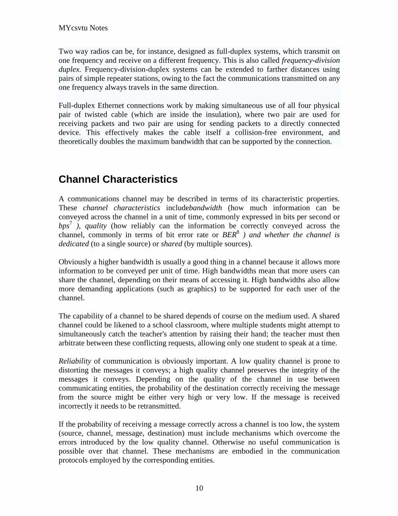
MYcsvtu Notes
10
Two way radios can be for instance designed as full-duplex systems which transmit on
one frequency and receive on a different frequency This is also called frequency-division
duplex Frequency-division-duplex systems can be extended to farther distances using
pairs of simple repeater stations owing to the fact the communications transmitted on any
one frequency always travels in the same direction
Full-duplex Ethernet connections work by making simultaneous use of all four physical
pair of twisted cable (which are inside the insulation) where two pair are used for
receiving packets and two pair are using for sending packets to a directly connected
device This effectively makes the cable itself a collision-free environment and
theoretically doubles the maximum bandwidth that can be supported by the connection
Channel Characteristics
A communications channel may be described in terms of its characteristic properties
These channel characteristics includebandwidth (how much information can be
conveyed across the channel in a unit of time commonly expressed in bits per second or
bps7 ) quality (how reliably can the information be correctly conveyed across the
channel commonly in terms of bit error rate or BER8 ) and whether the channel is
dedicated (to a single source) or shared (by multiple sources)
Obviously a higher bandwidth is usually a good thing in a channel because it allows more
information to be conveyed per unit of time High bandwidths mean that more users can
share the channel depending on their means of accessing it High bandwidths also allow
more demanding applications (such as graphics) to be supported for each user of the
channel
The capability of a channel to be shared depends of course on the medium used A shared
channel could be likened to a school classroom where multiple students might attempt to
simultaneously catch the teachers attention by raising their hand the teacher must then
arbitrate between these conflicting requests allowing only one student to speak at a time
Reliability of communication is obviously important A low quality channel is prone to
distorting the messages it conveys a high quality channel preserves the integrity of the
messages it conveys Depending on the quality of the channel in use between
communicating entities the probability of the destination correctly receiving the message
from the source might be either very high or very low If the message is received
incorrectly it needs to be retransmitted
If the probability of receiving a message correctly across a channel is too low the system
(source channel message destination) must include mechanisms which overcome the
errors introduced by the low quality channel Otherwise no useful communication is
possible over that channel These mechanisms are embodied in the communication
protocols employed by the corresponding entities
MYcsvtu Notes
11
The effective bandwidth describes what an application experiences and depends on the
quality of service (QOS) provided by the channel For example modems scale back their
transmission speed based largely on their perception of channel quality in order to
optimally use the transmission medium
In general shared and reliable channels are more resource efficient than those which
enjoy neither of these characteristics Shared channels enjoy greater efficiency than
dedicated ones because most data communication is bursty in nature with long idle
periods punctuated by brief message transmissions Reliable channels are more efficient
than unreliable ones because retransmissions are not required as often (because there are
fewer transmission-induced errors)
The OSI Reference Model
The Open Systems Interconnect (OSI) reference model is commonly used to describe in
an abstract manner the functions involved in data communication This model originally
conceived in the International Organization for Standardization (ISO) defines data
communications functions in terms of layers
In the OSI reference model each layer is responsible for certain basic functions such as
getting data from one device to another or from one application on a computer to another
The functions at each layer both depend and build on the functions-called services-
provided by the layers below it Communication between peer entities at a given layer is
done via one or more protocols this communication is invoked via the interface with the
layer below
The OSI reference model is depicted in Table 01 Successful communication between
two applications depends on successful functions at all seven layers In terms of
implementation it is possible for some layers to be trivial in the end what is required
depends on the needs of the applications (and people) engaged in communication
Table 01 OSI Reference Model
Layer Title
7 Application
Higher Layers 6 Presentation
5 Session
4 Transport
MYcsvtu Notes
12
3 Network
Lower Layers 2 Data Link
1 Physical
We must emphasize that the definition of a layered data communication architecture is
only an abstraction The intent of this definition is to unambiguously describe the
functions involved in data communication in a way which allows different systems to be
compared The OSI reference model definition is intended to neither imply nor constrain
the implementation of any communication system
Although various companies and standards bodies have created different layered
communications models the OSI reference model remains the universally-accepted
common denominator for abstract definition Other models define the layer functions
somewhat differently and often have fewer than seven layers In some cases constituent
protocols were specified before the abstract models defining the end-to-end
communication
We will now review the functions of the OSI layers and some of the primary protocols at
each layer9
Layer 1 - The Physical Layer
The physical layer functions include all physical aspects of communicating between two
directly-connected physical entities Typically these physical properties include
electromechanical characteristics of the medium or link between the communicating
physical entities such as connectors voltages transmission frequencies etc This layer
summarizes the physics which underlie the communication path
The essential service provided by the physical layer consists of an unstructured bit
stream which can be used by higher layers to provide the basis for higher layer
communication services An example of a physical layer is the ink on paper used by this
book to convey information Another example is the radio frequencies used in a wireless
communications system
Layer 2 - The Data Link Layer
The data link layer accepts the unstructured bit stream provided by the physical layer and
provides reliable transfer of data between two directly-connected Layer 2 entities
Directly-connected means that the Layer 2 entities communication path does not
require another Layer 2 entity However this does not imply a dedicated path in the case
MYcsvtu Notes
13
of Ethernet many Layer 2 entities can be sharing a common (physical) medium such as a
coaxial cable or a 10BASE-T hub
Layer 2 functionality is limited in scope-delivery of messages over a local area It could
be likened to an intra-office correspondence between co-workers there is a need for
reliability but addressing is relatively simple Local area networks (LANs) operate at
Layer 2
The data link layer is itself conceptually subdivided into two sublayers-medium access
control and logical link control-which more specifically define the primary aspects of
data link layer functionality However this conceptual partitioning by the IEEE 802
committee is somewhat arbitrary and subject to debate
The MAC Sublayer
The medium access control (MAC) sublayer is closely associated with the physical layer
and defines the means by which the physical channel (medium) may be accessed It
coordinates the attempts to seize a shared channel by multiple MAC entities much as a
school teacher must arbitrate between pupils conflicting desires to speak The MAC layer
commonly provides a limited form of error control especially for any header information
which defines the MAC-level destination and higher-layer access mechanism
Ethernet (IEEE 8023) is a prime example of a shared medium with a defined MAC
sublayer functionality The shared medium in Ethernet has traditionally consisted of a
coaxial cable into which multiple entities were tapped as depicted in Figure 05
Although this topology still applies conceptually a hub and spoke medium is now
typically used in which the earlier coaxial cable has been physically collapsed into a hub
device
Figure 05 Ethernet MAC System
11
As a contention medium Ethernet defines how devices sense a channel for its
availability wait when it is busy seize the channel when it becomes available and back-
off for a random length of time following a collision with another simultaneously
MYcsvtu Notes
14
transmitting device On a shared channel such as Ethernet only a single entity can
transmit at a time or messages will be garbled
Not all shared channels involve contention A prime example of a contentionless shared
medium is token ring (IEEE 8025) in which control of the channel is rotated between
the devices sharing the channel in a deterministic round-robin manner Conceptually
control of the channel is given to the entity currently possessing a token If the device
has nothing to transmit it passes the token to the next device attached to the topological
ring depicted in Figure 06
Figure 06 Token Ring MAC System
11
IEEE-defined MAC sublayer addresses are six bytes long and permanently assigned to
each device typically called a network interface card orNIC The IEEE administers the
assignment of these addresses in blocks to manufacturers to assure the global uniqueness
that the MAC sublayer protocols rely on for plug Ocircn play network setup Each
manufacturer must assure individual device identifier uniqueness within their assigned
block
The LLC Sublayer
The logical link control (LLC) sublayer is responsible for reliable transfer of messages-
called frames or more formally link protocol data units (LPDUs)-between two directly-
connected Layer 2 entities Functions needed to support this reliable transfer include
framing (indicating where a Layer 2 message begins and ends) sequence control error
control and flow control
MYcsvtu Notes
15
The degree to which sequence error and flow control are provided by the LLC sublayer
is determined by whether the link protocol is connection-oriented or connectionless A
connectionless link protocol provides little if any support for these functions A
connection-oriented link might use a windowing technique for these functions in which
frames are individually numbered and acknowledged by their sequence number with
only a few such frames outstanding at any time
The connection-oriented functions of sequencing error and flow control provide a
foundation for services provided by higher layers As mentioned earlier not all layer or
sublayer functions are explicitly designed or implemented in any given system Provision
of these functions depends on the services required by higher layers
If the connection-oriented functions of the LLC sublayer are not implemented they must
be performed by higher layers for reliable end-to-end communication If these functions
are provided by several layers they might be somewhat redundant and add unnecessary
overhead (inefficiency) to the system In the worst case redundant provision of these
functions at multiple layers could serve cross purposes and actually degrade overall
system performance
An example of a connectionless LLC protocol is frame relay (T1617 618) which
defines point-to-point links with switches connecting individual links in a mesh topology
In a frame relay network endpoints are connected by a series of links and switches
Because frame relay is defined in terms of the links between frame relay access devices
(FRADs) and switches and between switches themselves it is an LLC protocol
Connectionless Layer 2 protocols are best suited for high quality transmission media
With high quality transmission media errors are rarely introduced in the transmission
between network layer entities and discovery of and recovery from errors is most
efficiently handled by the communicating hosts In this case it is better to move the
packets quickly across the traversed subnetworks from source to destination rather than
checking for errors at Layer 2
Frame relay is derived from the X25 (ISO 8208) protocol which spans Layers 2 and 3
X25 is a connection-oriented packet-switching technology which defines how
neighboring packet switches exchange data with one another in a reliable manner from
end-to-end Frame relay simply removes the connection-oriented functions of error and
sequence control however congestion control functions are provided in frame relay to
prevent the total traffic seen at any point in the network from overwhelming it
Connection-oriented Layer 2 protocols are best suited for low quality transmission media
where it is more efficient and cost-effective to discover and recover from errors as they
occur on each hop than to rely on the communicating hosts to perform error recovery
functions With ever-increasing quality of transmission facilities and decreasing costs of
computation capability at hosts the need for connection-oriented network layer protocols
is diminishing However X25 remains popular outside of North America where it has
been tariffed at levels which encourage its use
MYcsvtu Notes
16
End-to-end communications may be via shared or dedicated facilities or circuits Shared
facilities involve the use of packet switching technology to carry messages from end-to-
end messages are subdivided as necessary into packets which share physical and logical
channels with packets from various sources to various destinations Packet switching is
almost universally used in data communications because it is more efficient for the bursty
nature of data traffic
On the other hand some applications require dedicated facilities from end-to-end because
they are isochronous (eg voice) or bandwidth-intensive (eg large file transfer) This
mode of end-to-end circuit dedication is called circuit switched communication Because
the facilities are dedicated to a single user this tends to be much more expensive than the
packet switched mode of communication But some applications need it-it is an economic
trade-off
Dedicated circuits are a rather extreme form of connection-oriented protocol requiring
the same setup and tear-down phases prior to and following communication If the circuit
setup and tear-down is statically arranged (ie out-of-band) it is referred to as a
permanent virtual circuit or PVC If the circuit is dynamically setup and torn-down in-
band it is referred to as a switched virtual circuit or SVC
Layer 3 - The Network Layer
The network layer defines the functions necessary to support data communication
between indirectly-connected entities It provides the capability of forwarding messages
from one Layer 3 entity to another until the final destination is reached
The network layer introduces another layer of abstraction to the data communications
model It moves messages-called packets or more formally network protocol data units
(NPDUs)-between communicating Layer 3 entities-called end systems nodes or hosts
Network layer functions include route determination or routing and forwarding of
packets to their final destinations
In order to forward a packet to its destination host routing information must be provided
to theintermediate systems (ISs) or routers responsible for forwarding packets to their
respective destinations This routing information includes the address of the destination
which is contained in each packet The next hop to be traversed by the packet is
determined primarily by this destination address We will talk more about addressing and
routing in Chapter 1
This packet forwarding and routing is accomplished independent of both the media and
transmission types used at any step along the way The unimportance of local topology to
the network layer is demonstrated by the common use of cloud diagrams to depict
networks as in Figure 07 Since the network layer is concerned with getting packets
across many local networks called subnetworks its title would be more accurate if it
were the Internetwork Layer
MYcsvtu Notes
17
Figure 07 Network Layer ``Cloud
Diagram
11
The network layer functionality is global in scope-delivery of messages over a wide area
It could be likened to the postal system in which correspondence is passed from location
to location until it eventually reaches the destination address on the envelope10
The
network layer is the domain of wide area networks (WANs)
In order for routers to know how (ie on which link) to forward packets they must have
some knowledge of network topology This knowledge may be complete or partial and is
dynamically created and maintained via routing protocols used by routers to share their
knowledge of network topology with each other Routing is essentially the reduction of
global internetwork topology to local hop-by-hop routing decisions made
independently by each router
As with Layer 2 Layer 3 protocols may be connection-oriented or connectionless A
connection-oriented Layer 3 protocol such as X25 (ISO 8208) operates more statically
The basic idea is that an end-to-end route (X25 virtual connection) is established from
the originating data terminal equipment (DTE) to data communications equipment
(DCE) from DCE to DCE through the network then from the last DCE to the
terminating DTE this is the call setup Packets are then transmitted via this prearranged
route with all packets following the same path through the network Finally the route is
torn down (release) and packets cease flowing
X25 operation is like a phone call because it is a phone call X25 Layer 3 operation
assumes that a reliable connection-oriented service is provided by Layer 2 (also defined
by the X25 standard) although it does provide flow control via sequence numbers
Connectionless Layer 3 protocols such as the ever popular internet protocol (IP)(RFC11
791 and 792) and its ISO counterpart connectionless network protocol (CLNP) (ISO
MYcsvtu Notes
18
8473) route packets dynamically There is no prearranged path which is followed by
subsequent packets flowing from one host to another Instead each packet is individually
routed through a routing mesh there is no reason to believe that sequential packets
flowing between hosts will follow the same path So sequence errors may be introduced
at Layer 3 which must be corrected by a higher layer entity
Connectionless data packets are commonly referred to as datagrams and the service
provided by connectionless Layer 3 protocols is referred to as datagram service Stateless
datagram service is simpler for Layer 3 entities than connection-oriented network layer
services Because there is no state information to maintain dynamic routing protocols can
be used If a router fails during the dialogue between two communicating hosts
neighboring routers will discover this via the routing protocols and find alternate routes
which bypass the failed router
There seems to be a fair amount of ambiguity between the network layer and the LLC
sublayer Both can provide connection-oriented or connectionless services to higher
layers To a large extent if Layer 3 is explicitly implemented there is no need for an
LLC sublayer The primary difference is in scope-LLC addresses and protocols are
oriented toward a more local environment whereas network layer addresses and protocols
are global in scope
Excellent references to routing and forwarding of data packets can be found in [PERL92]
and [STEN95]
Layer 4 - The Transport Layer
The transport layer is concerned with getting Layer 4 messages-called segments or more
formally transport protocol data units (TPDUs) -from source to destination in a reliable
manner The perspective of Layer 4 is of end-to-end communications rather than the hop-
by-hop perspective of Layer 3 Layer 4 assumes that packets can be moved from network
entity to network entity eventually getting to the final destination host How this is
accomplished is of no concern to Layer 4 functionality
Like other layers transport layer protocols can be either connection-oriented or
connectionless depending on the services required by higher layers A common
implementation of Layers 3 and 4 involves a connection-oriented transport layer protocol
running over a connectionless network layer protocol such as the ubiquitous TCPIP
protocol suite In this instance the communicating hosts maintain state information on
communications with each other to determine when and what to send This state
information defines the connection between the communicating Layer 4 entities
The general idea here is that two communicating hosts need not be concerned with the
topology of the internetwork which lies between them They only need to know the state
of their pairwise communication If part of the intervening internetwork cloud suffers a
failure the Layer 3 entities (routers) will deal with it and recover dynamically Aside
MYcsvtu Notes
19
from potential retransmission of any lost segments the hosts Layer 4 entries do not have
to be at all concerned with routing and recovery activities at Layer 3
In the IP protocol suite the primary connectionless Layer 4 protocol is the User
Datagram Protocol (UDP)(RFC 768) which is carried by IP the primary connection-
oriented protocol is the Transmission Control Protocol (TCP)(RFC 793) The ISO world
defines five classes of transport layer protocol beginning with Class 0 (TP-0) for
connectionless operation and range up to Class 4 (TP-4)(ISO 8073) for connection-
oriented operation
Layer 5 - The Session Layer
The session layer provides a control structure for communication between applications
on hosts The communication at layer 5 is called a session which defines the relative
timing of communications between the hosts applications Synchronization of
communicating applications comes into play when coordinated timing of corresponding
events at the endpoints is imperative such as in financial transactions
Remember layers define communication functions not implementations It is unlikely
that a session layer would be explicitly implemented as a stand-alone program although
its functions would be implemented somewhere Session layer functions depend on the
reliability of communications between the endpoints and session layer functions must
therefore be implemented above Layer 4
Layer 6 - The Presentation Layer
The presentation layer performs any necessary data transformations or formatting
required by the end applications Functions provided by the presentation layer include
data compression file formatting and encryption Common data formatting is important
because it allows the same application file to be accessed by the application running on
different computer platforms This book is itself the product of an application running on
different platforms with common files being modified via these different platforms
Abstract Syntax Notation (ASN1) is commonly used to specify data values in a way
which allows processors to communicate independent of their varying native integer
sizes bit orderings (big or little endian) character sets etc ASN1 is a transfer syntax a
presentation layer formatting which appears frequently in the CDPD specification for
unambiguous definition of network management accounting limited size messaging and
other functions
An example of ASN1 encoding from an accounting Traffic Matrix Segment in the
CDPD specification is the following
MYcsvtu Notes
20
TrafficType = INTEGER
registration (0)
deregistration (1)
ip(2)
clnp(3)
Layer 7 - The Application Layer
The application layer provides the services which directly support an application running
on a host These services are directly accessible by an application via common well-
known application program interfaces (APIs) which can actually occur at many layers
Examples of layer 7 services include FTP (file transfer protocol) Telnet and SNMP
(simple network management protocol) Most network management activities are based
on the services provided by layer 7 application entities which in turn rely on lower layer
services to be able to perform their functions
7 Application ECHO ENRP FTP Gopher HTTP NFS RTSP SIP SMTP SNMP
SSH Telnet Whois XMPP
6 Presentation XDR ASN1 SMB AFP NCP
5 Session ASAP TLS SSL ISO 8327 CCITT X225 RPC NetBIOS ASP
4 Transport TCP UDP RTP SCTP SPX ATP IL
3 Network IP ICMP IGMP IPX OSPF RIP IGRP EIGRP ARP RARP X25
2 Data Link Ethernet Token ring HDLC Frame relay ISDN ATM 80211 WiFi
FDDI PPP
1 Physical 10BASE-T 100BASE-T 1000BASE-T SONETSDH G709 T-
carrierE-carrier various 80211 physical layers
The TCPIP Reference Model
The TCPIP reference model is the network model used in the current Internet
architecture [19] It has its origins back in the 1960s with the grandfather of the Internet
the ARPANET This was a research network sponsored by the Department of Defense in
the United States The following were seen as major design goals
ability to connect multiple networks together seamlessly
ability for connections to remain intact as long as the source and destination
machines were functioning
MYcsvtu Notes
21
to be built on flexible architecture
The reference model was named after two of its main protocols TCP (Transmission
Control Protocol) [12] and IP (Internet Protocol)
They choose to build a packet-switched network based on a connectionless internetwork
layer
Figure 21 TCPIP Network Protocol
A detailed description of the reference model is beyond the scope of this document and
project The basic idea of the networking system is to allow one application on a host
computer to talk to another application on a different host computer
The application forms its request then passes the packet down to the lower layers which
add their own control information either a header or a footer onto the packet Finally the
packet reaches the physical layer and is transmitted through the cable onto the destination
host The packet then travels up through the different layers with each layer reading
deciphering and removing the header or footer that was attached by its counterpart on the
originating computer Finally the packet arrives at the application it was destined for
Even though technically each layer communicates with the layer above or below it the
process can be viewed as one layer talking to its partner on the host as figure 21 shows
The Host-to-Network Layer
The Host-to-Network layer interfaces the TCPIP protocol stack to the physical network
The TCPIP reference model does not specify in any great detail the operation of this
layer except that the host has to connect to the network using some protocol so it can
send IP packets over it
As it is not officially defined it varies from implementation to implementation with
vendors supplying their own version
MYcsvtu Notes
22
The Network Layer
The job of the network layer is to inject packets into any network and have them travel
independently to the destination The layer defines IP (Internet Protocol) for its official
packet format and protocol Packet routing is a major job of this protocol
The Transport Layer
The transport layer is the interface between the application layer and the complex
hardware of the network It is designed to allow peer entities on the source and
destination hosts to carry on conversations
Data may be user data or control data Two modes are available full-duplex and half
duplex In full-duplex operation both sides can transmit and receive data simultaneously
whereas in half duplex a side can only send or receive at one time
Interaction between the transport layer and the layers immediately above and below are
shown in figure 22 Any program running in the application layer has the ability to send
a message using TCP or UDP which are the two protocols defined for the transport layer
The application can communicate with the TCP or the UDP service whichever it
requires Both the TCP and UDP communicate with the Internet Protocol in the internet
layer In all cases communication is a two way process The applications can read and
write to the transport layer The diagram only shows two protocols in the transport layer
TTCP will also reside in this layer between the other two protocols and function in the
same manner
Figure 22 Interaction with Application Transport and Internet Layers
A message to be sent originates in the application layer This is then passed down onto
the appropriate protocol in the transport layer These protocols add a header to the
message for the corresponding transport layer in the destination machine for purposes of
reassembling the message The segment is then passed onto the internet layer where the
Internet Protocol adds a further header Finally the segment is passed onto the physical
MYcsvtu Notes
23
layer a header and a trailer are added at this stage Figure 23 shows the structure of the
final segment being sent
Figure 23 Transmitted Segment from TCPIP Network
The Application Layer
The original TCPIP specification described a number of different applications that fit
into the top layer of the protocol stack These applications include Telnet FTP SMTP
and DNS
Telnet is a program that supports the TELNET [13] protocol over TCP TELNET is a
general two-way communication protocol that can be used to connect to another host and
run applications on that host remotely
FTP (File Transfer Protocol) [14] is a protocol that was originally designed to promote
the sharing of files among computer users It shields the user from the variations of file
storage on different architectures and allows for a reliable and efficient transfer of data
SMTP (Simple Mail Transport Protocol) [15] is the protocol used to transport electronic
mail from one computer to another through a series of other computers along the route
DNS [10] (Domain Name System) resolves the numerical address of a network node into
its textual name or vice-versa It would translate wwwyahoocom to 2047117771 to
allow the routing protocols to find the host that the packet is destined for
What is a Topology
The physical topology of a network refers to the configuration of cables computers and
other peripherals Physical topology should not be confused with logical topology which
is the method used to pass information between workstations Logical topology was
discussed in the Protocol chapter
Main Types of Physical Topologies
The following sections discuss the physical topologies used in networks and other related
topics
Linear Bus
MYcsvtu Notes
24
Star
Star-Wired Ring
Tree
Considerations When Choosing a Topology
Summary Chart
Linear Bus
A linear bus topology consists of a main run of cable with a terminator at each end (See
fig 1) All nodes (file server workstations and peripherals) are connected to the linear
cable Ethernet and LocalTalk networks use a linear bus topology
Fig 1 Linear Bus topology
Advantages of a Linear Bus Topology
Easy to connect a computer or peripheral to a linear bus
Requires less cable length than a star topology
Disadvantages of a Linear Bus Topology
Entire network shuts down if there is a break in the main cable
Terminators are required at both ends of the backbone cable
Difficult to identify the problem if the entire network shuts down
Not meant to be used as a stand-alone solution in a large building
Star
A star topology is designed with each node (file server workstations and peripherals)
connected directly to a central network hub or concentrator (See fig 2)
Data on a star network passes through the hub or concentrator before continuing to its
destination The hub or concentrator manages and controls all functions of the network It
also acts as a repeater for the data flow This configuration is common with twisted pair
cable however it can also be used with coaxial cable or fiber optic cable
MYcsvtu Notes
25
Fig 2 Star topology
Advantages of a Star Topology
Easy to install and wire
No disruptions to the network then connecting or removing devices
Easy to detect faults and to remove parts
Disadvantages of a Star Topology
Requires more cable length than a linear topology
If the hub or concentrator fails nodes attached are disabled
More expensive than linear bus topologies because of the cost of the
concentrators
The protocols used with star configurations are usually Ethernet or LocalTalk Token
Ring uses a similar topology called the star-wired ring
Star-Wired Ring
A star-wired ring topology may appear (externally) to be the same as a star topology
Internally the MAU (multistation access unit) of a star-wired ring contains wiring that
allows information to pass from one device to another in a circle or ring (See fig 3) The
Token Ring protocol uses a star-wired ring topology
Tree
A tree topology combines characteristics of linear bus and star topologies It consists of
groups of star-configured workstations connected to a linear bus backbone cable (See fig
MYcsvtu Notes
26
4) Tree topologies allow for the expansion of an existing network and enable schools to
configure a network to meet their needs
Fig 4 Tree topology
Advantages of a Tree Topology
Point-to-point wiring for individual segments
Supported by several hardware and software venders
Disadvantages of a Tree Topology
Overall length of each segment is limited by the type of cabling used
If the backbone line breaks the entire segment goes down
More difficult to configure and wire than other topologies
5-4-3 Rule
A consideration in setting up a tree topology using Ethernet protocol is the 5-4-3 rule
One aspect of the Ethernet protocol requires that a signal sent out on the network cable
reach every part of the network within a specified length of time Each concentrator or
repeater that a signal goes through adds a small amount of time This leads to the rule that
between any two nodes on the network there can only be a maximum of 5 segments
connected through 4 repeatersconcentrators In addition only 3 of the segments may be
populated (trunk) segments if they are made of coaxial cable A populated segment is one
which has one or more nodes attached to it In Figure 4 the 5-4-3 rule is adhered to The
MYcsvtu Notes
27
furthest two nodes on the network have 4 segments and 3 repeatersconcentrators
between them
This rule does not apply to other network protocols or Ethernet networks where all fiber
optic cabling or a combination of a fiber backbone with UTP cabling is used If there is a
combination of fiber optic backbone and UTP cabling the rule is simply translated to 7-
6-5 rule
] Mesh
Full
Fully Connected The type of network topology in which each of the nodes of the network is
connected to each of the other nodes in the network with a point-to-point link ndash
this makes it possible for data to be simultaneously transmitted from any single
node to all of the other nodes
Note The physical fully connected mesh topology is generally too costly and
complex for practical networks although the topology is used when there are only
a small number of nodes to be interconnected[3]
Partial
Partially Connected The type of network topology in which some of the nodes of the network are
connected to more than one other node in the network with a point-to-point link ndash
this makes it possible to take advantage of some of the redundancy that is
provided by a physical fully connected mesh topology without the expense and
complexity required for a connection between every node in the network
Note In most practical networks that are based upon the physical partially
connected mesh topology all of the data that is transmitted between nodes in the
network takes the shortest path between nodes except in the case of a failure or
break in one of the links in which case the data takes an alternate path to the
destination ndash this implies that the nodes of the network possess some type of
logical routing algorithm to determine the correct path to use at any particular
time
[edit] Hybrid Network Topologies
The hybrid topology is a type of network topology that is composed of one or more
interconnections of two or more networks that are based upon different physical
topologies or a type of network topology that is composed of one or more
interconnections of two or more networks that are based upon the same physical
topology but where the physical topology of the network resulting from such an
interconnection does not meet the definition of the original physical topology of the
interconnected networks (eg the physical topology of a network that would result from
an interconnection of two or more networks that are based upon the physical star
topology might create a hybrid topology which resembles a mixture of the physical star
MYcsvtu Notes
28
and physical bus topologies or a mixture of the physical star and the physical tree
topologies depending upon how the individual networks are interconnected while the
physical topology of a network that would result from an interconnection of two or more
networks that are based upon the physical distributed bus network retains the topology of
a physical distributed bus network)
Star-Bus A type of network topology in which the central nodes of one or more individual
networks that are based upon the physical star topology are connected together
using a common bus network whose physical topology is based upon the
physical linear bus topology the endpoints of the common bus being terminated
with the characteristic impedance of the transmission medium where required ndash
eg two or more hubs connected to a common backbone with drop cables
through the port on the hub that is provided for that purpose (eg a properly
configured uplink port) would comprise the physical bus portion of the physical
star-bus topology while each of the individual hubs combined with the
individual nodes which are connected to them would comprise the physical star
portion of the physical star-bus topology
Star-of-Stars
Hierarchical Star A type of network topology that is composed of an interconnection of individual
networks that are based upon the physical star topology connected together in a
hierarchical fashion to form a more complex network ndash eg a top level central
node which is the hub of the top level physical star topology and to which other
second level central nodes are attached as the spoke nodes each of which in
turn may also become the central nodes of a third level physical star topology
Notes 1) The physical hierarchical star topology is not a combination of the physical
linear bus and the physical star topologies as cited in some texts as there is no
common linear bus within the topology although the top level hub which is the
beginning of the physical hierarchical star topology may be connected to the
backbone of another network such as a common carrier which is topologically
not considered to be a part of the local network ndash if the top level central node is
connected to a backbone that is considered to be a part of the local network then
the resulting network topology would be considered to be a hybrid topology that
is a mixture of the topology of the backbone network and the physical hierarchical
star topology
2) The physical hierarchical star topology is also sometimes incorrectly referred
to as a physical tree topology since its physical topology is hierarchical however
the physical hierarchical star topology does not have a structure that is determined
by a branching factor as is the case with the physical tree topology and therefore
nodes may be added to or removed from any node that is the hub of one of the
individual physical star topology networks within a network that is based upon the
physical hierarchical star topology
3) The physical hierarchical star topology is commonly used in outside plant
(OSP) cabling to connect various buildings to a central connection facility which
MYcsvtu Notes
29
may also house the demarcation point for the connection to the data transmission
facilities of a common carrier and in inside plant (ISP) cabling to connect
multiple wiring closets within a building to a common wiring closet within the
same building which is also generally where the main backbone or trunk that
connects to a larger network if any enters the building
Star-wired Ring A type of hybrid physical network topology that is a combination of the physical
star topology and the physical ring topology the physical star portion of the
topology consisting of a network in which each of the nodes of which the network
is composed are connected to a central node with a point-to-point link in a hub
and spoke fashion the central node being the hub and the nodes that are
attached to the central node being the spokes (eg a collection of point-to-point
links from the peripheral nodes that converge at a central node) in a fashion that is
identical to the physical star topology while the physical ring portion of the
topology consists of circuitry within the central node which routes the signals on
the network to each of the connected nodes sequentially in a circular fashion
Note In an 8025 Token Ring network the central node is called a Multistation
Access Unit (MAU)
Hybrid Mesh A type of hybrid physical network topology that is a combination of the physical
partially connected topology and one or more other physical topologies the mesh
portion of the topology consisting of redundant or alternate connections between
some of the nodes in the network ndash the physical hybrid mesh topology is
commonly used in networks which require a high degree of availability
Considerations When Choosing a Topology
Money A linear bus network may be the least expensive way to install a network
you do not have to purchase concentrators
Length of cable needed The linear bus network uses shorter lengths of cable
Future growth With a star topology expanding a network is easily done by
adding another concentrator
Cable type The most common cable in schools is unshielded twisted pair which
is most often used with star topologies
Summary Chart
Common Cable Common Protocol
Linear Bus Twisted Pair
Coaxial
Ethernet
LocalTalk
MYcsvtu Notes
30
Fiber
Star Twisted Pair
Fiber
Ethernet
LocalTalk
Star-Wired Ring Twisted Pair Token Ring
Tree
Twisted Pair
Coaxial
Fiber
Ethernet
Internet vs Web
The Internet and the World Wide Web are not synonymous the Internet is a collection of
interconnected computer networks linked by copper wires fiber-optic cables wireless
connections etc the Web is a collection of interconnected documents and other
resources linked by hyperlinks and URLs The World Wide Web is accessible via the
Internet as are many other services including e-mail file sharing and others described
below
The best way to define and distinguish between these terms is to understand the Internet
protocol suite This collection of protocols is organized into layers such that each layer
provides the foundation and the services required by the layer above In this conception
the term Internet refers to computer networks that all communicate with IP (Internet
protocol) and TCP (transfer control protocol) Once this networking structure is
established then other protocols can run ―on top These other protocols are sometimes
called services or applications Hypertext transfer protocol or HTTP is an application
layer protocol that links billions of files together into the World Wide Web
Common uses of the Internet
The World Wide Web
Through keyword-driven Internet research using search engines like Google
millions worldwide have easy instant access to a vast and diverse amount of
online information Compared to encyclopedias and traditional libraries the
World Wide Web has enabled a sudden and extreme decentralization of
information and data
Many individuals and some companies and groups have adopted the use of Web logs or
blogs which are largely used as easily-updatable online diaries Some commercial
organizations encourage staff to fill them with advice on their areas of specialization in
the hope that visitors will be impressed by the expert knowledge and free information
and be attracted to the corporation as a result One example of this practice is Microsoft
MYcsvtu Notes
31
whose product developers publish their personal blogs in order to pique the publics
interest in their work
For more information on the distinction between the World Wide Web and the Internet
itself mdash as in everyday use the two are sometimes confused mdash see Dark internet where
this is discussed in more detail
Remote access
The Internet allows computer users to connect to other computers and information stores
easily wherever they may be across the world They may do this with or without the use
of security authentication and encryption technologies depending on the requirements
This is encouraging new ways of working from home collaboration and information
sharing in many industries An accountant sitting at home can audit the books of a
company based in another country on a server situated in a third country that is remotely
maintained by IT specialists in a fourth These accounts could have been created by
home-working book-keepers in other remote locations based on information e-mailed to
them from offices all over the world Some of these things were possible before the
widespread use of the Internet but the cost of private leased lines would have made
many of them infeasible in practice
An office worker away from his desk perhaps the other side of the world on a business
trip or a holiday can open a remote desktop session into his normal office PC using a
secure Virtual Private Network (VPN) connection via the Internet This gives him
complete access to all his normal files and data including e-mail and other applications
while he is away
This concept is also referred to by some network security people as the Virtual Private
Nightmare because it extends the secure perimeter of a corporate network into its
employees homes this has been the source of some notable security breaches but also
provides security for the workers
Functions
File-sharing
Instant messaging
Internet fax
Search engine
World Wide Web
MYcsvtu Notes
32
Intranets
What are Intranets
bull Intranet is Intra+ Net so an Intranet is an internal or private Internet used strictly
within the confines of a company university or organization Inter means
between or among hence the difference between the Internet and an Intranet
Some formal definitions of Intranets
bull Brown amp Duguid ―Intranets help present and
circulate boundary objects
bull Choo Detlor amp Turnbull ―Intranetshellip support the creation sharing and use of
knowledge
bull Stenmark ―Intranets are organizationally
restricted
A technical definition
bull An Intranet is a network based on the internet TCPIP open standard An intranet
belongs to an organization and is designed to be accessible only by the
organizations members employees or others with authorization An intranets
Web site looks and act just like other Web sites but has a firewall surrounding it
to fend off unauthorized users
Design Of Intranets
Steps
bull Analyze the organizationlsquos information ecology
bull Identify the typical problems experienced by users
bull Analyze the information behaviors of these set of users
bull Create value added processes to resolve the problems of users and to improve the
Information Ecology
Value Added Processes
bull Intranets may be designed to improve the organizational information ecology
MYcsvtu Notes
33
bull Intranets provide a unified information space in which users can communicate
and collaborate with others
bull intranet applications and services may add value by supporting the organizationlsquos
knowledge creating and decision making process
Two Models of Online Environments
Centralized
Distributed
Centralized Environments
bull Before the web the centralized model was all we had (examples include
CompuServe Prodigy)
bull On the web centralized models include site-based services such as Yahoo
bull Most (all) college and university services are offered using the centralized
model
MYcsvtu Notes
34
bull But centralized environments are static inflexible expensive
Distributed Environments
bull The World Wide Web is an example of a distributed environment
bull Resources access are not centralized but scattered around the world
ndash Resources in the form of a network of connected (via DNS) web servers
ndash Access in the form of a network of connected (via DNS) internet service
providers
ndash Users in the form of individualized and connected (via HTTP) web
browsers
bull The big issue ndash integration ndash that is making different systems work together
Design Principles
Network Design Principles
ndash Specifies how networks differ from traditional learning
ndash The idea is that each principle confers an advantage over non-network
systems
ndash Can be used as a means of evaluating new technology
1 Decentralize
ndash Centralized networks have a characteristic starlsquo shape
bull Some entities have many connections
bull The vast majority have few
bull Eg broadcast network teacher in a classroom
ndash Decentralized networks form a mesh
bull The weight of connections flow is distributed
bull Balanced load = more stable
bull Foster connections between entities fill outlsquo the star
Distribute
ndash Network entities reside in different physical locations
bull Reduces risk of network failure
bull Reduces need for major infrastructure such as powerful servers
large bandwidth massive storage
ndash Examples
bull Peer-to-peer networks such as Kazaa Gnutella
bull Content syndication networks such as RSS
ndash Emphasis is on sharing not copying
bull Locallsquo copies are temporary
MYcsvtu Notes
35
Computer Graphics
Computer Graphics is about animation (films)
Games are very important in Computer Graphics
Medical Imaging is another driving force
Computer Aided Design too
Graphics Definitions
bull Point
ndash a location in space 2D or 3D
ndash sometimes denotes one pixel
bull Line
ndash straight path connecting two points
ndash infinitesimal width consistent density
ndash beginning and end on points
bull Vertex
ndash point in 3D
bull Edge
ndash line in 3D connecting two vertices
bull PolygonFaceFacet
ndash arbitrary shape formed by connected vertices
ndash fundamental unit of 3D computer graphics
bull Raster
ndash derived from TV systems for a row of pixels
ndash commonly referred to as a scanline
ndash does influence algorithms ndash reducing memory requirements parallelism
etc
ndash is the derivation of rasterization scan-line algorithms
Displays
bull Most desktop displays use a cathode ray tube (CRT) while portable computing
devices such as laptops incorporate liquid crystal display (LCD)
bull Because of their slimmer design and smaller energy consumption monitors using
LCD technologies are beginning to replace the venerable CRT on many desktops
Cathode-Ray Tubes
MYcsvtu Notes
36
bull Classical output device is a monitor
bull Cathode-Ray Tube (CRT)
ndash Invented by Karl Ferdinand Braun (1897)
ndash Beam of electrons directed from cathode (-)to phosphor-coated
(fluorescent) screen (anode (+))
ndash Directed by magnetic focusing and deflection coils (anodes) in vacuum
filled tube
ndash Phosphor emits photon of light when hit by an electron of varied
persistence (long 15-20 ms for texts short lt 1ms for animation)
ndash Refresh rate (50-60 Hz 72-76 Hz) to avoid flicker trail
ndash Phosphors are organic compounds characterized by their persistence and
their color (blue red green)
Cathode-Ray Tubes
bull Cathode-Ray Tube (CRT)
ndash Horizontal deflection and vertical deflection direct the electron beam to
any point on the screen
ndash Intensity knob regulates the flow of electrons by controlling the voltage at
the control grid (high voltage reduces the electron density and thus
brightness)
ndash Accelerating voltage from positive coating inside screen (anode screen) or
an accelerating anode
bull Image maintenance
ndash Charge distribution to store picture information
OR
ndash Refresh CRT refreshes the display constantly to maintain phosphor glow
Cathode-Ray Tubes
bullCathode-Ray Tube (CRT)
ndash Horizontal deflection and vertical deflection direct the electron beam to any point
on the screen
ndash Intensity knob regulates the flow of electrons by controlling the voltage at the
control grid (high voltage reduces the electron density and thus brightness)
ndash Accelerating voltage from positive coating inside screen (anode screen) or an
accelerating anode
bullImage maintenance
ndash Charge distribution to store picture information
OR
ndash Refresh CRT refreshes the display constantly to maintain phosphor glow
bull Characteristics of Cathode-Ray Tube (CRT)
MYcsvtu Notes
37
ndash Intensity is proportional to the number of electrons repelled in beam per
second (brightness)
ndash Resolution is the maximum number of points that can be displayed
without overlap is expressed as number of horizontal points by number of
vertical points points are called pixels (picture elements) example
resolution 1024 x 768 pixels Typical resolution is 1280 x 1024 pixels
bull High-definition systems high resolution systems
bull Focusing
ndash Focusing forces the electron beam to converge to a point on the monitor
screen
ndash Can be electrostatic (lens) or magnetic (field)
bull Deflection
ndash Deflection directs the electron beam horizontally andor vertically to any
point on the screen
ndash Can be controlled by electric (deflection plates slide 9) or magnetic fields
(deflection coils slide 5)
ndash Magnetic coils two pairs (topbottom leftright) of tube neck
ndash Electric plates two pairs (horizontal vertical)
Raster-scan Displays
bullVideo displays can be either raster-scan or random-scan displays
bullRaster-scan display is the most common type of monitor using a CRT
bullThe electron beam scans the screen from top to bottom one row at a time Each row is
called a scan line
bullThe electron beam is turned on and off to produce a collection of dots painted one row at
a time These will form the image
bullA raster is a matrix of pixels covering the screen area and is composed of raster lines
Raster-scan Displays
MYcsvtu Notes
38
Raster-scan Displays
bullThe image is stored in a frame buffer containing the total screen area and where each
memory location corresponds to a pixel
bullIn a monochrome system each bit is 1 or 0 for the corresponding pixel to be on or off
(bitmap)
bullThe display processor scans the frame buffer to turn electron beam onoff depending if
the bit is 1 or 0
bullFor color monitors the frame buffer also contains the color of each pixel (color buffer)
as well as other characteristics of the image (gray scale hellip) 8 bitspixel 0255
(pixmap)
bullDepth of the buffer area is the number of bits per pixel (bit planes) up to 24
bullExamples television panels printers PC monitors (99 of raster-scan)
Raster-scan Displays
bullRefresh rate 24 is a minimum to avoid flicker corresponding to 24 Hz (1 Hz = 1 refresh
per second)
bullCurrent raster-scan displays have a refresh rate of at least 60 frames (60 Hz) per second
up to 120 (120 Hz)
bullUses large memory 640x480 307200 bits 38 kB
bullRefresh procedure
MYcsvtu Notes
39
ndashHorizontal retrace ndash beam returns to left of screen
ndashVertical retrace ndash bean returns to top left corner of screen
ndashInterlaced refresh ndash display first even-numbered lines then odd-numbered lines
permits to see the image in half the time
useful for slow refresh rates (30 Hz shows as 60 Hz)
Random-scan Displays
bullRandom scan systems are also called vector stroke-writing or calligraphic displays
bullThe electron beam directly draws the picture in any specified order
bullA pen plotter is an example of such a system
bullPicture is stored in a display list refresh display file vector file or display program as a
set of line drawing commands
bullRefreshes by scanning the list 30 to 60 times per second
bullMore suited for line-drawing applications such as architecture and manufacturing
Random-scan Displays
bullAdvantages
ndashHigh resolution
ndashEasy animation
ndashRequires little memory
bullDisadvantages
ndashRequires intelligent electron beam (processor controlled)
ndashLimited screen density limited to simple line-based images
ndashLimited color capability
bullImproved in the 1960lsquos by the Direct View Storage Tube (DVST) from Tektronix
Color CRT Monitor
Uses different phosphors a combination of Red Green and Blue to produce any color
Two methods
Random scan uses beam penetration
2 layers (Red Green) phosphors low speed electrons excite Red high speed electrons
excite Green interrmediate speed excite both to get yellow and orange Color is
controlled by electron beam voltage
Only produces a restricted set of colors
Raster scan uses a shadow mask with three electron guns Red Green and Blue (RGB
color model) Color is produced by adjusting the intensity level of each electron beam
Produces a wide range of colors from 8 to several millions
Raster scan
Most common as found in televisions
Beam scanned left to right flicked back to rescan from top to bottom then repeated
Repeated at 30Hz per frame sometimes higher to reduce flicker Interlacing scanning
MYcsvtu Notes
40
odd lines in whole screen then even lines is also used to reduce flicker Can also use
high-persistence phosphor to reduce flicker but causes image smearing especially with
significant animation
Resolution typically 512x512 but high-quality screens are available (and becoming more
common) at up to approximately 1600x1200 pixels Sun workstations have screens of
1192x980 pixels
Black amp white screens can display grayscale by varying the intensity of the electron
beam
Colour is achieved using three electron guns which hit red green or blue phosphors
Combining these colours can produce many others including white (all on) Phosphor
dots focused using a shadow mask - makes colour screens lower resolution than
monochrome
Alternative approach beam penetration Special phosphor glows a different colour
depending on intensity of beam
Colour or intensity at pixel held by computerlsquos video card 1 bitpixel can store offon
information hence only black ampwhite More bitspixel give rise to more colour
possibilities eg 8 bitspixel gives rise to 2^8=256 possible colours at any one time
Random Scan (Directed-beam refresh vector display)
Instead of scanning the whole display sequentially and horizontally the random scan
draws the lines to be displayed directly Screen update at gt30Hz to reduce flicker
Jaggies not found and higher resolutions possible (up to 4096x4096 pixels) Colour
achieved using beam penetration generally of poorer quality Eye strain and fatigue still
a problem and vector displays are more expensive
Direct view storage tube (DVST)
Used a lot in analogue storage oscilloscopes
Similar to random scan crt but image maintained by flood guns - no flicker Can be
incrementally updated but not selectively erased image has to be redrawn on completely
erased screen High resolution (typically 4096x3120 pixels) but low contrast low
brightness and difficulty in displaying colour
What is a Multimedia System
bull A system that involves
ndash generation
ndash representation
ndash storage
ndash transmission
ndash search and retrieval
ndash delivery
MYcsvtu Notes
41
of multimedia information
productionauthoring tools
compression and formats
file system design
networking issues
database management
server design streaming
Multimedia System Architecture
Information management subsystem Presentation Query
Storage subsystem Efficiently stored
amp retrieved
Network subsystem Delivery
Adaptation in Multimedia Systems
bull Multimedia systems can profit a lot from personalization
ndash User behavior
ndash User properties
bull Adaptation
ndash Models
ndash Mechanisms
Multimedia in a mobile environment
MYcsvtu Notes
42
bull Applications
ndash Emergency response systems mobile commerce phone service
entertainment games
What is Sound
A ripple is a pressure wave in water created by an object striking the water
Sound is a pressure wave in air created for example by an object such as a string
or our vocal cords vibrating Dark here represents more pressure light represents
less
MYcsvtu Notes
43
Sine Waves Form Pure Tones
This simple sound wave is a Sine Wave a Pure tone produced by a simple vibration
Sine Wave Sample Tone
This can be represented graphically as shown above
Converting Pressure into Voltage
The pressure wave of sound moves a diaphragm in the microphone which produces a
voltage proportional to the pressure of the sound wave at each instant
Animation
MYcsvtu Notes
44
bull Animation is the rapid display of a sequence of images of 2-D artwork or model
positions in order to create an illusion of movement It is an optical illusion of
motion due to the phenomenon of persistence of vision This could be anything
from a flip book to a motion picture film Animation deals with the generation
sequencing and display a set of images which is called frames to create an effect
of visual change or motion similar to a movie film
bull Animation is used in those instance where videography is not possible
Hardware Requirement For Animation
bull Image Generation Tools amp Devices
bull Computer monitors with image display Capability
Software Requirement For Animation
bull Animation creating software
bull Screen Capture Software
bull Animation Clips
bull Software support For High Resolution
bull Recording amp Playback Capability
bull Transition effect
Early animation
There is no single person that can be considered the creator of the art of animation as
there were several people doing several projects which could be considered various types
of animation all around the same time (Short hand-drawn animation scenes could be
presented with the Phenakistoscope the Zoetrope and other optical toys already in the
early 1800s)
The following is a brief listing on those who are often acknowledged as significant to the
development of animation Note that this list is by no means a comprehensive list of
contributors to early animation
Georges Meacuteliegraves was a creator of special effect films such as A Trip to the Moon He
used many techniques ndash one of which was to stop the camera rolling change something
in the scene and then continue rolling the film This is a very similar idea to that of stop-
motion animation Meacuteliegraves accidentally happened upon the technique when his camera
broke down while shooting a bus driving by When the camera was fixed a horse
happened to be passing by just as Meacuteliegraves continued to film The result was that the bus
appeared to change into a horse
MYcsvtu Notes
45
Fantasmagorie by Emile Cohl 1908
Eacutemile Cohl began drawing cartoon strips and created a film in 1908 called
Fantasmagorie The film largely consisted of a stick figure moving about and
encountering all manner of morphing objects such as a wine bottle that transforms into a
flower There were also sections of live action where the animatorlsquos hands would enter
the scene The film was created by drawing each frame on paper and then shooting each
frame onto negative film which gave the picture a blackboard look
Winsor McCay created detailed animations that required a team of artists and painstaking
attention for detail Each frame was drawn on paper requiring backgrounds to be
redrawn as well characters to be animated His films such as Gertie the Dinosaur (1914)
and The Sinking of the Lusitania (1918) were of an impressive scale although The
Sinking of the Lusitania used cels
In 1919 Otto Messmer created the character of Felix the cat for Pat Sullivans animation
studios The importance of Felix lies in the characters strong personality created largely
through gesture and actions
Animation techniques
Animation techniques are incredibly varied and difficult to categorize Techniques are
often related or combined The following is a brief on common types of animation
Again this list is by no means comprehensive
Traditional animation
An example of traditional animation a horse animated by rotoscoping from Edweard
Muybridges 19th century photos
Main article Traditional animation
MYcsvtu Notes
46
Also called cel animation the frames of a traditionally animated movie are hand-drawn
The drawings are traced or copied onto transparent acetate sheets called cels which are
then placed over a painted background and photographed one by one on a rostrum
camera Nowadays the use of cels (and cameras) is mostly obsolete since the drawings
are scanned into computers and digitally transferred directly to 35 mm film The look
of traditional cel animation is still preserved and the character animators work has
remained essentially the same over the past 70 years Because of the digital influence
over modern cel animation it is also known as tradigital animation
Examples The Lion King Spirited Away Les Triplettes de Belleville
Full animation The most common style in animation known for its realistic and often very detailed art
Examples All Disney feature length animated films The Secret of NIMH The Iron Giant
Limited animation A cheaper process of making animated cartoons that does not follow a realistic
approach
Examples The Flintstones Yellow Submarine
Rubber hose The characters are usually cartoony and the animators have a lot of artistic freedom as
rubber hose animations dont have to follow the laws of physics and anatomy in the same
degree as the other main styles in animation
Examples Early Mickey Mouse cartoons Ren and Stimpy Popeye
Rotoscoping A technique where animators trace live action movement frame by frame for use in
animated films
Examples Gullivers Travels American Pop
Stop motion
Stop-motion animation is any type of animation which requires the animator to physically
alter the scene shoot a frame again alter the scene and shoot a frame and so on to create
the animation There are many different types of stop-motion animation some noteable
examples are listed below
Clay animation
MYcsvtu Notes
47
A clay animation scene from a TV commercial
Often abbreviated to claymation this is a type of stop-motion animation using
figures made of clay or a similar malleable material The figures may have an
armature or wire frame inside of them similar to puppet animation (below)
Alternatively the figures may be made entirely of clay such as in the films of
Bruce Bickford where clay creatures morph into a variety of different shapes
Examples Wallace and Gromit Dimensions of Dialogue by Jan Švankmajer The
Amazing Mr Bickford The Trap Door
Cutout animation In this type of stop-motion animation the animation is formed by moving 2-
dimensional pieces of material such as paper or cloth
Examples the animated sequences of Monty Pythons Flying Circus (often
referred to as Dada animation named after the Dada art movement[citation needed]
)
Tale of Tales early episodes of South Park
Silhouette animation A type of cutout animation where the viewer only sees black silhouettes
Example The Adventures of Prince Achmed the worlds oldest surviving
animated feature film from 1926
Graphic animation
Model animation In this form of animation model animated characters interact with and are a part
of the live-action world
Examples The films of Ray Harryhausen (Jason and the Argonauts) and Willis
OBrien (King Kong)
Go motion
Object animation
Pixilation Examples Neighbours
Puppet animation Puppet animation typically involves puppet figures interacting with each other in
a constructed environment in contrast to the real-world interaction in model
MYcsvtu Notes
48
animation (above) The puppets generally have an armature inside of them to
keep them still and steady as well as constraining them to move at particular
joints
Examples The Nightmare Before Christmas Robot Chicken The Tale of the Fox
Brickfilm
Puppetoon
Computer animation
A short gif animation
Like stop motion computer animation encompasses a variety of techniques the unifying
idea being that the animation is created digitally on a computer
2D animation Figures are created andor edited on the computer using 2D bitmap graphics or
created and edited using 2D vector graphics This includes automated
computerized versions of traditional animation techniques such as of tweening
morphing onion skinning and interpolated rotoscoping
Examples A Scanner Darkly Jib Jab
Analog computer animation
Flash animation
PowerPoint animation
A completely synthetic computer-generated scene
3D animation
MYcsvtu Notes
49
Figures are created in the computer using polygons To allow these meshes to
move they are given a digital armature (sculpture) This process is called rigging
Various other techniques can be applied such as mathematical functions
(gravity) simulated fur or hair effects such as fire and water and the use of
motion capture to name but a few
Examples The Incredibles Shrek
Cel-shaded animation
Morph target animation
Skeletal animation
Motion capture
Crowd simulation
Less common techniques
Drawn on film animation A technique where footage is produced by creating the
images directly on film stock
Paint-on-glass animationA technique for making animated films by manipulating slow-
drying oil paints on sheets of glass
Pinscreen animation Makes use of a screen filled with movable pins which can be
moved in or out by pressing an object onto the screen The screen is lit from the side so
that the pins cast shadows The technique has been used to create animated films with a
range of textural effects difficult to achieve with traditional cel animation
Sand animation Sand is moved around on a backlighted or frontlighted piece of glass to
create each frame for an animated film
Multimedia
Multimedia (Lat Multum + Medium) is media that uses multiple forms of information
content and information processing (eg text audio graphics animation video
interactivity) to inform or entertain the (user) audience Multimedia also refers to the use
of (but not limited to) electronic media to store and experience multimedia content
Multimedia is similar to traditional mixed media in fine art but with a broader scope The
term rich media is synonymous for interactive multimedia
Categorization
Multimedia may be broadly divided into linear and non-linear categories Linear active
content progresses without any navigation control for the viewer such as a cinema
presentation Non-linear content offers user interactivity to control progress as used with
MYcsvtu Notes
50
a computer game or used in self-paced computer based training Non-linear content is
also known as hypermedia content
Multimedia presentations can be live or recorded A recorded presentation may allow
interactivity via a navigation system A live multimedia presentation may allow
interactivity via interaction with the presenter or performer
There are 2 basic way to represent some information
Unimedium Presentation
Multimedia Presentation
In case of computer system the commonly used medioa for the purpose of storage
access and transmission of information are
bull Text
bull Graphics
bull Animation
bull Audio
bull Video
Multimedia Computer System require
bull Faster CPU
bull Larger Storage Devices
bull Larger Main Memory
bull Good Graphics Terminal
bull IO devices required to play an audio associated with the program
Transmission Mode
bull Asynchronous
bull Synchronous
bull Isochronous
MYcsvtu Notes
11
The effective bandwidth describes what an application experiences and depends on the
quality of service (QOS) provided by the channel For example modems scale back their
transmission speed based largely on their perception of channel quality in order to
optimally use the transmission medium
In general shared and reliable channels are more resource efficient than those which
enjoy neither of these characteristics Shared channels enjoy greater efficiency than
dedicated ones because most data communication is bursty in nature with long idle
periods punctuated by brief message transmissions Reliable channels are more efficient
than unreliable ones because retransmissions are not required as often (because there are
fewer transmission-induced errors)
The OSI Reference Model
The Open Systems Interconnect (OSI) reference model is commonly used to describe in
an abstract manner the functions involved in data communication This model originally
conceived in the International Organization for Standardization (ISO) defines data
communications functions in terms of layers
In the OSI reference model each layer is responsible for certain basic functions such as
getting data from one device to another or from one application on a computer to another
The functions at each layer both depend and build on the functions-called services-
provided by the layers below it Communication between peer entities at a given layer is
done via one or more protocols this communication is invoked via the interface with the
layer below
The OSI reference model is depicted in Table 01 Successful communication between
two applications depends on successful functions at all seven layers In terms of
implementation it is possible for some layers to be trivial in the end what is required
depends on the needs of the applications (and people) engaged in communication
Table 01 OSI Reference Model
Layer Title
7 Application
Higher Layers 6 Presentation
5 Session
4 Transport
MYcsvtu Notes
12
3 Network
Lower Layers 2 Data Link
1 Physical
We must emphasize that the definition of a layered data communication architecture is
only an abstraction The intent of this definition is to unambiguously describe the
functions involved in data communication in a way which allows different systems to be
compared The OSI reference model definition is intended to neither imply nor constrain
the implementation of any communication system
Although various companies and standards bodies have created different layered
communications models the OSI reference model remains the universally-accepted
common denominator for abstract definition Other models define the layer functions
somewhat differently and often have fewer than seven layers In some cases constituent
protocols were specified before the abstract models defining the end-to-end
communication
We will now review the functions of the OSI layers and some of the primary protocols at
each layer9
Layer 1 - The Physical Layer
The physical layer functions include all physical aspects of communicating between two
directly-connected physical entities Typically these physical properties include
electromechanical characteristics of the medium or link between the communicating
physical entities such as connectors voltages transmission frequencies etc This layer
summarizes the physics which underlie the communication path
The essential service provided by the physical layer consists of an unstructured bit
stream which can be used by higher layers to provide the basis for higher layer
communication services An example of a physical layer is the ink on paper used by this
book to convey information Another example is the radio frequencies used in a wireless
communications system
Layer 2 - The Data Link Layer
The data link layer accepts the unstructured bit stream provided by the physical layer and
provides reliable transfer of data between two directly-connected Layer 2 entities
Directly-connected means that the Layer 2 entities communication path does not
require another Layer 2 entity However this does not imply a dedicated path in the case
MYcsvtu Notes
13
of Ethernet many Layer 2 entities can be sharing a common (physical) medium such as a
coaxial cable or a 10BASE-T hub
Layer 2 functionality is limited in scope-delivery of messages over a local area It could
be likened to an intra-office correspondence between co-workers there is a need for
reliability but addressing is relatively simple Local area networks (LANs) operate at
Layer 2
The data link layer is itself conceptually subdivided into two sublayers-medium access
control and logical link control-which more specifically define the primary aspects of
data link layer functionality However this conceptual partitioning by the IEEE 802
committee is somewhat arbitrary and subject to debate
The MAC Sublayer
The medium access control (MAC) sublayer is closely associated with the physical layer
and defines the means by which the physical channel (medium) may be accessed It
coordinates the attempts to seize a shared channel by multiple MAC entities much as a
school teacher must arbitrate between pupils conflicting desires to speak The MAC layer
commonly provides a limited form of error control especially for any header information
which defines the MAC-level destination and higher-layer access mechanism
Ethernet (IEEE 8023) is a prime example of a shared medium with a defined MAC
sublayer functionality The shared medium in Ethernet has traditionally consisted of a
coaxial cable into which multiple entities were tapped as depicted in Figure 05
Although this topology still applies conceptually a hub and spoke medium is now
typically used in which the earlier coaxial cable has been physically collapsed into a hub
device
Figure 05 Ethernet MAC System
11
As a contention medium Ethernet defines how devices sense a channel for its
availability wait when it is busy seize the channel when it becomes available and back-
off for a random length of time following a collision with another simultaneously
MYcsvtu Notes
14
transmitting device On a shared channel such as Ethernet only a single entity can
transmit at a time or messages will be garbled
Not all shared channels involve contention A prime example of a contentionless shared
medium is token ring (IEEE 8025) in which control of the channel is rotated between
the devices sharing the channel in a deterministic round-robin manner Conceptually
control of the channel is given to the entity currently possessing a token If the device
has nothing to transmit it passes the token to the next device attached to the topological
ring depicted in Figure 06
Figure 06 Token Ring MAC System
11
IEEE-defined MAC sublayer addresses are six bytes long and permanently assigned to
each device typically called a network interface card orNIC The IEEE administers the
assignment of these addresses in blocks to manufacturers to assure the global uniqueness
that the MAC sublayer protocols rely on for plug Ocircn play network setup Each
manufacturer must assure individual device identifier uniqueness within their assigned
block
The LLC Sublayer
The logical link control (LLC) sublayer is responsible for reliable transfer of messages-
called frames or more formally link protocol data units (LPDUs)-between two directly-
connected Layer 2 entities Functions needed to support this reliable transfer include
framing (indicating where a Layer 2 message begins and ends) sequence control error
control and flow control
MYcsvtu Notes
15
The degree to which sequence error and flow control are provided by the LLC sublayer
is determined by whether the link protocol is connection-oriented or connectionless A
connectionless link protocol provides little if any support for these functions A
connection-oriented link might use a windowing technique for these functions in which
frames are individually numbered and acknowledged by their sequence number with
only a few such frames outstanding at any time
The connection-oriented functions of sequencing error and flow control provide a
foundation for services provided by higher layers As mentioned earlier not all layer or
sublayer functions are explicitly designed or implemented in any given system Provision
of these functions depends on the services required by higher layers
If the connection-oriented functions of the LLC sublayer are not implemented they must
be performed by higher layers for reliable end-to-end communication If these functions
are provided by several layers they might be somewhat redundant and add unnecessary
overhead (inefficiency) to the system In the worst case redundant provision of these
functions at multiple layers could serve cross purposes and actually degrade overall
system performance
An example of a connectionless LLC protocol is frame relay (T1617 618) which
defines point-to-point links with switches connecting individual links in a mesh topology
In a frame relay network endpoints are connected by a series of links and switches
Because frame relay is defined in terms of the links between frame relay access devices
(FRADs) and switches and between switches themselves it is an LLC protocol
Connectionless Layer 2 protocols are best suited for high quality transmission media
With high quality transmission media errors are rarely introduced in the transmission
between network layer entities and discovery of and recovery from errors is most
efficiently handled by the communicating hosts In this case it is better to move the
packets quickly across the traversed subnetworks from source to destination rather than
checking for errors at Layer 2
Frame relay is derived from the X25 (ISO 8208) protocol which spans Layers 2 and 3
X25 is a connection-oriented packet-switching technology which defines how
neighboring packet switches exchange data with one another in a reliable manner from
end-to-end Frame relay simply removes the connection-oriented functions of error and
sequence control however congestion control functions are provided in frame relay to
prevent the total traffic seen at any point in the network from overwhelming it
Connection-oriented Layer 2 protocols are best suited for low quality transmission media
where it is more efficient and cost-effective to discover and recover from errors as they
occur on each hop than to rely on the communicating hosts to perform error recovery
functions With ever-increasing quality of transmission facilities and decreasing costs of
computation capability at hosts the need for connection-oriented network layer protocols
is diminishing However X25 remains popular outside of North America where it has
been tariffed at levels which encourage its use
MYcsvtu Notes
16
End-to-end communications may be via shared or dedicated facilities or circuits Shared
facilities involve the use of packet switching technology to carry messages from end-to-
end messages are subdivided as necessary into packets which share physical and logical
channels with packets from various sources to various destinations Packet switching is
almost universally used in data communications because it is more efficient for the bursty
nature of data traffic
On the other hand some applications require dedicated facilities from end-to-end because
they are isochronous (eg voice) or bandwidth-intensive (eg large file transfer) This
mode of end-to-end circuit dedication is called circuit switched communication Because
the facilities are dedicated to a single user this tends to be much more expensive than the
packet switched mode of communication But some applications need it-it is an economic
trade-off
Dedicated circuits are a rather extreme form of connection-oriented protocol requiring
the same setup and tear-down phases prior to and following communication If the circuit
setup and tear-down is statically arranged (ie out-of-band) it is referred to as a
permanent virtual circuit or PVC If the circuit is dynamically setup and torn-down in-
band it is referred to as a switched virtual circuit or SVC
Layer 3 - The Network Layer
The network layer defines the functions necessary to support data communication
between indirectly-connected entities It provides the capability of forwarding messages
from one Layer 3 entity to another until the final destination is reached
The network layer introduces another layer of abstraction to the data communications
model It moves messages-called packets or more formally network protocol data units
(NPDUs)-between communicating Layer 3 entities-called end systems nodes or hosts
Network layer functions include route determination or routing and forwarding of
packets to their final destinations
In order to forward a packet to its destination host routing information must be provided
to theintermediate systems (ISs) or routers responsible for forwarding packets to their
respective destinations This routing information includes the address of the destination
which is contained in each packet The next hop to be traversed by the packet is
determined primarily by this destination address We will talk more about addressing and
routing in Chapter 1
This packet forwarding and routing is accomplished independent of both the media and
transmission types used at any step along the way The unimportance of local topology to
the network layer is demonstrated by the common use of cloud diagrams to depict
networks as in Figure 07 Since the network layer is concerned with getting packets
across many local networks called subnetworks its title would be more accurate if it
were the Internetwork Layer
MYcsvtu Notes
17
Figure 07 Network Layer ``Cloud
Diagram
11
The network layer functionality is global in scope-delivery of messages over a wide area
It could be likened to the postal system in which correspondence is passed from location
to location until it eventually reaches the destination address on the envelope10
The
network layer is the domain of wide area networks (WANs)
In order for routers to know how (ie on which link) to forward packets they must have
some knowledge of network topology This knowledge may be complete or partial and is
dynamically created and maintained via routing protocols used by routers to share their
knowledge of network topology with each other Routing is essentially the reduction of
global internetwork topology to local hop-by-hop routing decisions made
independently by each router
As with Layer 2 Layer 3 protocols may be connection-oriented or connectionless A
connection-oriented Layer 3 protocol such as X25 (ISO 8208) operates more statically
The basic idea is that an end-to-end route (X25 virtual connection) is established from
the originating data terminal equipment (DTE) to data communications equipment
(DCE) from DCE to DCE through the network then from the last DCE to the
terminating DTE this is the call setup Packets are then transmitted via this prearranged
route with all packets following the same path through the network Finally the route is
torn down (release) and packets cease flowing
X25 operation is like a phone call because it is a phone call X25 Layer 3 operation
assumes that a reliable connection-oriented service is provided by Layer 2 (also defined
by the X25 standard) although it does provide flow control via sequence numbers
Connectionless Layer 3 protocols such as the ever popular internet protocol (IP)(RFC11
791 and 792) and its ISO counterpart connectionless network protocol (CLNP) (ISO
MYcsvtu Notes
18
8473) route packets dynamically There is no prearranged path which is followed by
subsequent packets flowing from one host to another Instead each packet is individually
routed through a routing mesh there is no reason to believe that sequential packets
flowing between hosts will follow the same path So sequence errors may be introduced
at Layer 3 which must be corrected by a higher layer entity
Connectionless data packets are commonly referred to as datagrams and the service
provided by connectionless Layer 3 protocols is referred to as datagram service Stateless
datagram service is simpler for Layer 3 entities than connection-oriented network layer
services Because there is no state information to maintain dynamic routing protocols can
be used If a router fails during the dialogue between two communicating hosts
neighboring routers will discover this via the routing protocols and find alternate routes
which bypass the failed router
There seems to be a fair amount of ambiguity between the network layer and the LLC
sublayer Both can provide connection-oriented or connectionless services to higher
layers To a large extent if Layer 3 is explicitly implemented there is no need for an
LLC sublayer The primary difference is in scope-LLC addresses and protocols are
oriented toward a more local environment whereas network layer addresses and protocols
are global in scope
Excellent references to routing and forwarding of data packets can be found in [PERL92]
and [STEN95]
Layer 4 - The Transport Layer
The transport layer is concerned with getting Layer 4 messages-called segments or more
formally transport protocol data units (TPDUs) -from source to destination in a reliable
manner The perspective of Layer 4 is of end-to-end communications rather than the hop-
by-hop perspective of Layer 3 Layer 4 assumes that packets can be moved from network
entity to network entity eventually getting to the final destination host How this is
accomplished is of no concern to Layer 4 functionality
Like other layers transport layer protocols can be either connection-oriented or
connectionless depending on the services required by higher layers A common
implementation of Layers 3 and 4 involves a connection-oriented transport layer protocol
running over a connectionless network layer protocol such as the ubiquitous TCPIP
protocol suite In this instance the communicating hosts maintain state information on
communications with each other to determine when and what to send This state
information defines the connection between the communicating Layer 4 entities
The general idea here is that two communicating hosts need not be concerned with the
topology of the internetwork which lies between them They only need to know the state
of their pairwise communication If part of the intervening internetwork cloud suffers a
failure the Layer 3 entities (routers) will deal with it and recover dynamically Aside
MYcsvtu Notes
19
from potential retransmission of any lost segments the hosts Layer 4 entries do not have
to be at all concerned with routing and recovery activities at Layer 3
In the IP protocol suite the primary connectionless Layer 4 protocol is the User
Datagram Protocol (UDP)(RFC 768) which is carried by IP the primary connection-
oriented protocol is the Transmission Control Protocol (TCP)(RFC 793) The ISO world
defines five classes of transport layer protocol beginning with Class 0 (TP-0) for
connectionless operation and range up to Class 4 (TP-4)(ISO 8073) for connection-
oriented operation
Layer 5 - The Session Layer
The session layer provides a control structure for communication between applications
on hosts The communication at layer 5 is called a session which defines the relative
timing of communications between the hosts applications Synchronization of
communicating applications comes into play when coordinated timing of corresponding
events at the endpoints is imperative such as in financial transactions
Remember layers define communication functions not implementations It is unlikely
that a session layer would be explicitly implemented as a stand-alone program although
its functions would be implemented somewhere Session layer functions depend on the
reliability of communications between the endpoints and session layer functions must
therefore be implemented above Layer 4
Layer 6 - The Presentation Layer
The presentation layer performs any necessary data transformations or formatting
required by the end applications Functions provided by the presentation layer include
data compression file formatting and encryption Common data formatting is important
because it allows the same application file to be accessed by the application running on
different computer platforms This book is itself the product of an application running on
different platforms with common files being modified via these different platforms
Abstract Syntax Notation (ASN1) is commonly used to specify data values in a way
which allows processors to communicate independent of their varying native integer
sizes bit orderings (big or little endian) character sets etc ASN1 is a transfer syntax a
presentation layer formatting which appears frequently in the CDPD specification for
unambiguous definition of network management accounting limited size messaging and
other functions
An example of ASN1 encoding from an accounting Traffic Matrix Segment in the
CDPD specification is the following
MYcsvtu Notes
20
TrafficType = INTEGER
registration (0)
deregistration (1)
ip(2)
clnp(3)
Layer 7 - The Application Layer
The application layer provides the services which directly support an application running
on a host These services are directly accessible by an application via common well-
known application program interfaces (APIs) which can actually occur at many layers
Examples of layer 7 services include FTP (file transfer protocol) Telnet and SNMP
(simple network management protocol) Most network management activities are based
on the services provided by layer 7 application entities which in turn rely on lower layer
services to be able to perform their functions
7 Application ECHO ENRP FTP Gopher HTTP NFS RTSP SIP SMTP SNMP
SSH Telnet Whois XMPP
6 Presentation XDR ASN1 SMB AFP NCP
5 Session ASAP TLS SSL ISO 8327 CCITT X225 RPC NetBIOS ASP
4 Transport TCP UDP RTP SCTP SPX ATP IL
3 Network IP ICMP IGMP IPX OSPF RIP IGRP EIGRP ARP RARP X25
2 Data Link Ethernet Token ring HDLC Frame relay ISDN ATM 80211 WiFi
FDDI PPP
1 Physical 10BASE-T 100BASE-T 1000BASE-T SONETSDH G709 T-
carrierE-carrier various 80211 physical layers
The TCPIP Reference Model
The TCPIP reference model is the network model used in the current Internet
architecture [19] It has its origins back in the 1960s with the grandfather of the Internet
the ARPANET This was a research network sponsored by the Department of Defense in
the United States The following were seen as major design goals
ability to connect multiple networks together seamlessly
ability for connections to remain intact as long as the source and destination
machines were functioning
MYcsvtu Notes
21
to be built on flexible architecture
The reference model was named after two of its main protocols TCP (Transmission
Control Protocol) [12] and IP (Internet Protocol)
They choose to build a packet-switched network based on a connectionless internetwork
layer
Figure 21 TCPIP Network Protocol
A detailed description of the reference model is beyond the scope of this document and
project The basic idea of the networking system is to allow one application on a host
computer to talk to another application on a different host computer
The application forms its request then passes the packet down to the lower layers which
add their own control information either a header or a footer onto the packet Finally the
packet reaches the physical layer and is transmitted through the cable onto the destination
host The packet then travels up through the different layers with each layer reading
deciphering and removing the header or footer that was attached by its counterpart on the
originating computer Finally the packet arrives at the application it was destined for
Even though technically each layer communicates with the layer above or below it the
process can be viewed as one layer talking to its partner on the host as figure 21 shows
The Host-to-Network Layer
The Host-to-Network layer interfaces the TCPIP protocol stack to the physical network
The TCPIP reference model does not specify in any great detail the operation of this
layer except that the host has to connect to the network using some protocol so it can
send IP packets over it
As it is not officially defined it varies from implementation to implementation with
vendors supplying their own version
MYcsvtu Notes
22
The Network Layer
The job of the network layer is to inject packets into any network and have them travel
independently to the destination The layer defines IP (Internet Protocol) for its official
packet format and protocol Packet routing is a major job of this protocol
The Transport Layer
The transport layer is the interface between the application layer and the complex
hardware of the network It is designed to allow peer entities on the source and
destination hosts to carry on conversations
Data may be user data or control data Two modes are available full-duplex and half
duplex In full-duplex operation both sides can transmit and receive data simultaneously
whereas in half duplex a side can only send or receive at one time
Interaction between the transport layer and the layers immediately above and below are
shown in figure 22 Any program running in the application layer has the ability to send
a message using TCP or UDP which are the two protocols defined for the transport layer
The application can communicate with the TCP or the UDP service whichever it
requires Both the TCP and UDP communicate with the Internet Protocol in the internet
layer In all cases communication is a two way process The applications can read and
write to the transport layer The diagram only shows two protocols in the transport layer
TTCP will also reside in this layer between the other two protocols and function in the
same manner
Figure 22 Interaction with Application Transport and Internet Layers
A message to be sent originates in the application layer This is then passed down onto
the appropriate protocol in the transport layer These protocols add a header to the
message for the corresponding transport layer in the destination machine for purposes of
reassembling the message The segment is then passed onto the internet layer where the
Internet Protocol adds a further header Finally the segment is passed onto the physical
MYcsvtu Notes
23
layer a header and a trailer are added at this stage Figure 23 shows the structure of the
final segment being sent
Figure 23 Transmitted Segment from TCPIP Network
The Application Layer
The original TCPIP specification described a number of different applications that fit
into the top layer of the protocol stack These applications include Telnet FTP SMTP
and DNS
Telnet is a program that supports the TELNET [13] protocol over TCP TELNET is a
general two-way communication protocol that can be used to connect to another host and
run applications on that host remotely
FTP (File Transfer Protocol) [14] is a protocol that was originally designed to promote
the sharing of files among computer users It shields the user from the variations of file
storage on different architectures and allows for a reliable and efficient transfer of data
SMTP (Simple Mail Transport Protocol) [15] is the protocol used to transport electronic
mail from one computer to another through a series of other computers along the route
DNS [10] (Domain Name System) resolves the numerical address of a network node into
its textual name or vice-versa It would translate wwwyahoocom to 2047117771 to
allow the routing protocols to find the host that the packet is destined for
What is a Topology
The physical topology of a network refers to the configuration of cables computers and
other peripherals Physical topology should not be confused with logical topology which
is the method used to pass information between workstations Logical topology was
discussed in the Protocol chapter
Main Types of Physical Topologies
The following sections discuss the physical topologies used in networks and other related
topics
Linear Bus
MYcsvtu Notes
24
Star
Star-Wired Ring
Tree
Considerations When Choosing a Topology
Summary Chart
Linear Bus
A linear bus topology consists of a main run of cable with a terminator at each end (See
fig 1) All nodes (file server workstations and peripherals) are connected to the linear
cable Ethernet and LocalTalk networks use a linear bus topology
Fig 1 Linear Bus topology
Advantages of a Linear Bus Topology
Easy to connect a computer or peripheral to a linear bus
Requires less cable length than a star topology
Disadvantages of a Linear Bus Topology
Entire network shuts down if there is a break in the main cable
Terminators are required at both ends of the backbone cable
Difficult to identify the problem if the entire network shuts down
Not meant to be used as a stand-alone solution in a large building
Star
A star topology is designed with each node (file server workstations and peripherals)
connected directly to a central network hub or concentrator (See fig 2)
Data on a star network passes through the hub or concentrator before continuing to its
destination The hub or concentrator manages and controls all functions of the network It
also acts as a repeater for the data flow This configuration is common with twisted pair
cable however it can also be used with coaxial cable or fiber optic cable
MYcsvtu Notes
25
Fig 2 Star topology
Advantages of a Star Topology
Easy to install and wire
No disruptions to the network then connecting or removing devices
Easy to detect faults and to remove parts
Disadvantages of a Star Topology
Requires more cable length than a linear topology
If the hub or concentrator fails nodes attached are disabled
More expensive than linear bus topologies because of the cost of the
concentrators
The protocols used with star configurations are usually Ethernet or LocalTalk Token
Ring uses a similar topology called the star-wired ring
Star-Wired Ring
A star-wired ring topology may appear (externally) to be the same as a star topology
Internally the MAU (multistation access unit) of a star-wired ring contains wiring that
allows information to pass from one device to another in a circle or ring (See fig 3) The
Token Ring protocol uses a star-wired ring topology
Tree
A tree topology combines characteristics of linear bus and star topologies It consists of
groups of star-configured workstations connected to a linear bus backbone cable (See fig
MYcsvtu Notes
26
4) Tree topologies allow for the expansion of an existing network and enable schools to
configure a network to meet their needs
Fig 4 Tree topology
Advantages of a Tree Topology
Point-to-point wiring for individual segments
Supported by several hardware and software venders
Disadvantages of a Tree Topology
Overall length of each segment is limited by the type of cabling used
If the backbone line breaks the entire segment goes down
More difficult to configure and wire than other topologies
5-4-3 Rule
A consideration in setting up a tree topology using Ethernet protocol is the 5-4-3 rule
One aspect of the Ethernet protocol requires that a signal sent out on the network cable
reach every part of the network within a specified length of time Each concentrator or
repeater that a signal goes through adds a small amount of time This leads to the rule that
between any two nodes on the network there can only be a maximum of 5 segments
connected through 4 repeatersconcentrators In addition only 3 of the segments may be
populated (trunk) segments if they are made of coaxial cable A populated segment is one
which has one or more nodes attached to it In Figure 4 the 5-4-3 rule is adhered to The
MYcsvtu Notes
27
furthest two nodes on the network have 4 segments and 3 repeatersconcentrators
between them
This rule does not apply to other network protocols or Ethernet networks where all fiber
optic cabling or a combination of a fiber backbone with UTP cabling is used If there is a
combination of fiber optic backbone and UTP cabling the rule is simply translated to 7-
6-5 rule
] Mesh
Full
Fully Connected The type of network topology in which each of the nodes of the network is
connected to each of the other nodes in the network with a point-to-point link ndash
this makes it possible for data to be simultaneously transmitted from any single
node to all of the other nodes
Note The physical fully connected mesh topology is generally too costly and
complex for practical networks although the topology is used when there are only
a small number of nodes to be interconnected[3]
Partial
Partially Connected The type of network topology in which some of the nodes of the network are
connected to more than one other node in the network with a point-to-point link ndash
this makes it possible to take advantage of some of the redundancy that is
provided by a physical fully connected mesh topology without the expense and
complexity required for a connection between every node in the network
Note In most practical networks that are based upon the physical partially
connected mesh topology all of the data that is transmitted between nodes in the
network takes the shortest path between nodes except in the case of a failure or
break in one of the links in which case the data takes an alternate path to the
destination ndash this implies that the nodes of the network possess some type of
logical routing algorithm to determine the correct path to use at any particular
time
[edit] Hybrid Network Topologies
The hybrid topology is a type of network topology that is composed of one or more
interconnections of two or more networks that are based upon different physical
topologies or a type of network topology that is composed of one or more
interconnections of two or more networks that are based upon the same physical
topology but where the physical topology of the network resulting from such an
interconnection does not meet the definition of the original physical topology of the
interconnected networks (eg the physical topology of a network that would result from
an interconnection of two or more networks that are based upon the physical star
topology might create a hybrid topology which resembles a mixture of the physical star
MYcsvtu Notes
28
and physical bus topologies or a mixture of the physical star and the physical tree
topologies depending upon how the individual networks are interconnected while the
physical topology of a network that would result from an interconnection of two or more
networks that are based upon the physical distributed bus network retains the topology of
a physical distributed bus network)
Star-Bus A type of network topology in which the central nodes of one or more individual
networks that are based upon the physical star topology are connected together
using a common bus network whose physical topology is based upon the
physical linear bus topology the endpoints of the common bus being terminated
with the characteristic impedance of the transmission medium where required ndash
eg two or more hubs connected to a common backbone with drop cables
through the port on the hub that is provided for that purpose (eg a properly
configured uplink port) would comprise the physical bus portion of the physical
star-bus topology while each of the individual hubs combined with the
individual nodes which are connected to them would comprise the physical star
portion of the physical star-bus topology
Star-of-Stars
Hierarchical Star A type of network topology that is composed of an interconnection of individual
networks that are based upon the physical star topology connected together in a
hierarchical fashion to form a more complex network ndash eg a top level central
node which is the hub of the top level physical star topology and to which other
second level central nodes are attached as the spoke nodes each of which in
turn may also become the central nodes of a third level physical star topology
Notes 1) The physical hierarchical star topology is not a combination of the physical
linear bus and the physical star topologies as cited in some texts as there is no
common linear bus within the topology although the top level hub which is the
beginning of the physical hierarchical star topology may be connected to the
backbone of another network such as a common carrier which is topologically
not considered to be a part of the local network ndash if the top level central node is
connected to a backbone that is considered to be a part of the local network then
the resulting network topology would be considered to be a hybrid topology that
is a mixture of the topology of the backbone network and the physical hierarchical
star topology
2) The physical hierarchical star topology is also sometimes incorrectly referred
to as a physical tree topology since its physical topology is hierarchical however
the physical hierarchical star topology does not have a structure that is determined
by a branching factor as is the case with the physical tree topology and therefore
nodes may be added to or removed from any node that is the hub of one of the
individual physical star topology networks within a network that is based upon the
physical hierarchical star topology
3) The physical hierarchical star topology is commonly used in outside plant
(OSP) cabling to connect various buildings to a central connection facility which
MYcsvtu Notes
29
may also house the demarcation point for the connection to the data transmission
facilities of a common carrier and in inside plant (ISP) cabling to connect
multiple wiring closets within a building to a common wiring closet within the
same building which is also generally where the main backbone or trunk that
connects to a larger network if any enters the building
Star-wired Ring A type of hybrid physical network topology that is a combination of the physical
star topology and the physical ring topology the physical star portion of the
topology consisting of a network in which each of the nodes of which the network
is composed are connected to a central node with a point-to-point link in a hub
and spoke fashion the central node being the hub and the nodes that are
attached to the central node being the spokes (eg a collection of point-to-point
links from the peripheral nodes that converge at a central node) in a fashion that is
identical to the physical star topology while the physical ring portion of the
topology consists of circuitry within the central node which routes the signals on
the network to each of the connected nodes sequentially in a circular fashion
Note In an 8025 Token Ring network the central node is called a Multistation
Access Unit (MAU)
Hybrid Mesh A type of hybrid physical network topology that is a combination of the physical
partially connected topology and one or more other physical topologies the mesh
portion of the topology consisting of redundant or alternate connections between
some of the nodes in the network ndash the physical hybrid mesh topology is
commonly used in networks which require a high degree of availability
Considerations When Choosing a Topology
Money A linear bus network may be the least expensive way to install a network
you do not have to purchase concentrators
Length of cable needed The linear bus network uses shorter lengths of cable
Future growth With a star topology expanding a network is easily done by
adding another concentrator
Cable type The most common cable in schools is unshielded twisted pair which
is most often used with star topologies
Summary Chart
Common Cable Common Protocol
Linear Bus Twisted Pair
Coaxial
Ethernet
LocalTalk
MYcsvtu Notes
30
Fiber
Star Twisted Pair
Fiber
Ethernet
LocalTalk
Star-Wired Ring Twisted Pair Token Ring
Tree
Twisted Pair
Coaxial
Fiber
Ethernet
Internet vs Web
The Internet and the World Wide Web are not synonymous the Internet is a collection of
interconnected computer networks linked by copper wires fiber-optic cables wireless
connections etc the Web is a collection of interconnected documents and other
resources linked by hyperlinks and URLs The World Wide Web is accessible via the
Internet as are many other services including e-mail file sharing and others described
below
The best way to define and distinguish between these terms is to understand the Internet
protocol suite This collection of protocols is organized into layers such that each layer
provides the foundation and the services required by the layer above In this conception
the term Internet refers to computer networks that all communicate with IP (Internet
protocol) and TCP (transfer control protocol) Once this networking structure is
established then other protocols can run ―on top These other protocols are sometimes
called services or applications Hypertext transfer protocol or HTTP is an application
layer protocol that links billions of files together into the World Wide Web
Common uses of the Internet
The World Wide Web
Through keyword-driven Internet research using search engines like Google
millions worldwide have easy instant access to a vast and diverse amount of
online information Compared to encyclopedias and traditional libraries the
World Wide Web has enabled a sudden and extreme decentralization of
information and data
Many individuals and some companies and groups have adopted the use of Web logs or
blogs which are largely used as easily-updatable online diaries Some commercial
organizations encourage staff to fill them with advice on their areas of specialization in
the hope that visitors will be impressed by the expert knowledge and free information
and be attracted to the corporation as a result One example of this practice is Microsoft
MYcsvtu Notes
31
whose product developers publish their personal blogs in order to pique the publics
interest in their work
For more information on the distinction between the World Wide Web and the Internet
itself mdash as in everyday use the two are sometimes confused mdash see Dark internet where
this is discussed in more detail
Remote access
The Internet allows computer users to connect to other computers and information stores
easily wherever they may be across the world They may do this with or without the use
of security authentication and encryption technologies depending on the requirements
This is encouraging new ways of working from home collaboration and information
sharing in many industries An accountant sitting at home can audit the books of a
company based in another country on a server situated in a third country that is remotely
maintained by IT specialists in a fourth These accounts could have been created by
home-working book-keepers in other remote locations based on information e-mailed to
them from offices all over the world Some of these things were possible before the
widespread use of the Internet but the cost of private leased lines would have made
many of them infeasible in practice
An office worker away from his desk perhaps the other side of the world on a business
trip or a holiday can open a remote desktop session into his normal office PC using a
secure Virtual Private Network (VPN) connection via the Internet This gives him
complete access to all his normal files and data including e-mail and other applications
while he is away
This concept is also referred to by some network security people as the Virtual Private
Nightmare because it extends the secure perimeter of a corporate network into its
employees homes this has been the source of some notable security breaches but also
provides security for the workers
Functions
File-sharing
Instant messaging
Internet fax
Search engine
World Wide Web
MYcsvtu Notes
32
Intranets
What are Intranets
bull Intranet is Intra+ Net so an Intranet is an internal or private Internet used strictly
within the confines of a company university or organization Inter means
between or among hence the difference between the Internet and an Intranet
Some formal definitions of Intranets
bull Brown amp Duguid ―Intranets help present and
circulate boundary objects
bull Choo Detlor amp Turnbull ―Intranetshellip support the creation sharing and use of
knowledge
bull Stenmark ―Intranets are organizationally
restricted
A technical definition
bull An Intranet is a network based on the internet TCPIP open standard An intranet
belongs to an organization and is designed to be accessible only by the
organizations members employees or others with authorization An intranets
Web site looks and act just like other Web sites but has a firewall surrounding it
to fend off unauthorized users
Design Of Intranets
Steps
bull Analyze the organizationlsquos information ecology
bull Identify the typical problems experienced by users
bull Analyze the information behaviors of these set of users
bull Create value added processes to resolve the problems of users and to improve the
Information Ecology
Value Added Processes
bull Intranets may be designed to improve the organizational information ecology
MYcsvtu Notes
33
bull Intranets provide a unified information space in which users can communicate
and collaborate with others
bull intranet applications and services may add value by supporting the organizationlsquos
knowledge creating and decision making process
Two Models of Online Environments
Centralized
Distributed
Centralized Environments
bull Before the web the centralized model was all we had (examples include
CompuServe Prodigy)
bull On the web centralized models include site-based services such as Yahoo
bull Most (all) college and university services are offered using the centralized
model
MYcsvtu Notes
34
bull But centralized environments are static inflexible expensive
Distributed Environments
bull The World Wide Web is an example of a distributed environment
bull Resources access are not centralized but scattered around the world
ndash Resources in the form of a network of connected (via DNS) web servers
ndash Access in the form of a network of connected (via DNS) internet service
providers
ndash Users in the form of individualized and connected (via HTTP) web
browsers
bull The big issue ndash integration ndash that is making different systems work together
Design Principles
Network Design Principles
ndash Specifies how networks differ from traditional learning
ndash The idea is that each principle confers an advantage over non-network
systems
ndash Can be used as a means of evaluating new technology
1 Decentralize
ndash Centralized networks have a characteristic starlsquo shape
bull Some entities have many connections
bull The vast majority have few
bull Eg broadcast network teacher in a classroom
ndash Decentralized networks form a mesh
bull The weight of connections flow is distributed
bull Balanced load = more stable
bull Foster connections between entities fill outlsquo the star
Distribute
ndash Network entities reside in different physical locations
bull Reduces risk of network failure
bull Reduces need for major infrastructure such as powerful servers
large bandwidth massive storage
ndash Examples
bull Peer-to-peer networks such as Kazaa Gnutella
bull Content syndication networks such as RSS
ndash Emphasis is on sharing not copying
bull Locallsquo copies are temporary
MYcsvtu Notes
35
Computer Graphics
Computer Graphics is about animation (films)
Games are very important in Computer Graphics
Medical Imaging is another driving force
Computer Aided Design too
Graphics Definitions
bull Point
ndash a location in space 2D or 3D
ndash sometimes denotes one pixel
bull Line
ndash straight path connecting two points
ndash infinitesimal width consistent density
ndash beginning and end on points
bull Vertex
ndash point in 3D
bull Edge
ndash line in 3D connecting two vertices
bull PolygonFaceFacet
ndash arbitrary shape formed by connected vertices
ndash fundamental unit of 3D computer graphics
bull Raster
ndash derived from TV systems for a row of pixels
ndash commonly referred to as a scanline
ndash does influence algorithms ndash reducing memory requirements parallelism
etc
ndash is the derivation of rasterization scan-line algorithms
Displays
bull Most desktop displays use a cathode ray tube (CRT) while portable computing
devices such as laptops incorporate liquid crystal display (LCD)
bull Because of their slimmer design and smaller energy consumption monitors using
LCD technologies are beginning to replace the venerable CRT on many desktops
Cathode-Ray Tubes
MYcsvtu Notes
36
bull Classical output device is a monitor
bull Cathode-Ray Tube (CRT)
ndash Invented by Karl Ferdinand Braun (1897)
ndash Beam of electrons directed from cathode (-)to phosphor-coated
(fluorescent) screen (anode (+))
ndash Directed by magnetic focusing and deflection coils (anodes) in vacuum
filled tube
ndash Phosphor emits photon of light when hit by an electron of varied
persistence (long 15-20 ms for texts short lt 1ms for animation)
ndash Refresh rate (50-60 Hz 72-76 Hz) to avoid flicker trail
ndash Phosphors are organic compounds characterized by their persistence and
their color (blue red green)
Cathode-Ray Tubes
bull Cathode-Ray Tube (CRT)
ndash Horizontal deflection and vertical deflection direct the electron beam to
any point on the screen
ndash Intensity knob regulates the flow of electrons by controlling the voltage at
the control grid (high voltage reduces the electron density and thus
brightness)
ndash Accelerating voltage from positive coating inside screen (anode screen) or
an accelerating anode
bull Image maintenance
ndash Charge distribution to store picture information
OR
ndash Refresh CRT refreshes the display constantly to maintain phosphor glow
Cathode-Ray Tubes
bullCathode-Ray Tube (CRT)
ndash Horizontal deflection and vertical deflection direct the electron beam to any point
on the screen
ndash Intensity knob regulates the flow of electrons by controlling the voltage at the
control grid (high voltage reduces the electron density and thus brightness)
ndash Accelerating voltage from positive coating inside screen (anode screen) or an
accelerating anode
bullImage maintenance
ndash Charge distribution to store picture information
OR
ndash Refresh CRT refreshes the display constantly to maintain phosphor glow
bull Characteristics of Cathode-Ray Tube (CRT)
MYcsvtu Notes
37
ndash Intensity is proportional to the number of electrons repelled in beam per
second (brightness)
ndash Resolution is the maximum number of points that can be displayed
without overlap is expressed as number of horizontal points by number of
vertical points points are called pixels (picture elements) example
resolution 1024 x 768 pixels Typical resolution is 1280 x 1024 pixels
bull High-definition systems high resolution systems
bull Focusing
ndash Focusing forces the electron beam to converge to a point on the monitor
screen
ndash Can be electrostatic (lens) or magnetic (field)
bull Deflection
ndash Deflection directs the electron beam horizontally andor vertically to any
point on the screen
ndash Can be controlled by electric (deflection plates slide 9) or magnetic fields
(deflection coils slide 5)
ndash Magnetic coils two pairs (topbottom leftright) of tube neck
ndash Electric plates two pairs (horizontal vertical)
Raster-scan Displays
bullVideo displays can be either raster-scan or random-scan displays
bullRaster-scan display is the most common type of monitor using a CRT
bullThe electron beam scans the screen from top to bottom one row at a time Each row is
called a scan line
bullThe electron beam is turned on and off to produce a collection of dots painted one row at
a time These will form the image
bullA raster is a matrix of pixels covering the screen area and is composed of raster lines
Raster-scan Displays
MYcsvtu Notes
38
Raster-scan Displays
bullThe image is stored in a frame buffer containing the total screen area and where each
memory location corresponds to a pixel
bullIn a monochrome system each bit is 1 or 0 for the corresponding pixel to be on or off
(bitmap)
bullThe display processor scans the frame buffer to turn electron beam onoff depending if
the bit is 1 or 0
bullFor color monitors the frame buffer also contains the color of each pixel (color buffer)
as well as other characteristics of the image (gray scale hellip) 8 bitspixel 0255
(pixmap)
bullDepth of the buffer area is the number of bits per pixel (bit planes) up to 24
bullExamples television panels printers PC monitors (99 of raster-scan)
Raster-scan Displays
bullRefresh rate 24 is a minimum to avoid flicker corresponding to 24 Hz (1 Hz = 1 refresh
per second)
bullCurrent raster-scan displays have a refresh rate of at least 60 frames (60 Hz) per second
up to 120 (120 Hz)
bullUses large memory 640x480 307200 bits 38 kB
bullRefresh procedure
MYcsvtu Notes
39
ndashHorizontal retrace ndash beam returns to left of screen
ndashVertical retrace ndash bean returns to top left corner of screen
ndashInterlaced refresh ndash display first even-numbered lines then odd-numbered lines
permits to see the image in half the time
useful for slow refresh rates (30 Hz shows as 60 Hz)
Random-scan Displays
bullRandom scan systems are also called vector stroke-writing or calligraphic displays
bullThe electron beam directly draws the picture in any specified order
bullA pen plotter is an example of such a system
bullPicture is stored in a display list refresh display file vector file or display program as a
set of line drawing commands
bullRefreshes by scanning the list 30 to 60 times per second
bullMore suited for line-drawing applications such as architecture and manufacturing
Random-scan Displays
bullAdvantages
ndashHigh resolution
ndashEasy animation
ndashRequires little memory
bullDisadvantages
ndashRequires intelligent electron beam (processor controlled)
ndashLimited screen density limited to simple line-based images
ndashLimited color capability
bullImproved in the 1960lsquos by the Direct View Storage Tube (DVST) from Tektronix
Color CRT Monitor
Uses different phosphors a combination of Red Green and Blue to produce any color
Two methods
Random scan uses beam penetration
2 layers (Red Green) phosphors low speed electrons excite Red high speed electrons
excite Green interrmediate speed excite both to get yellow and orange Color is
controlled by electron beam voltage
Only produces a restricted set of colors
Raster scan uses a shadow mask with three electron guns Red Green and Blue (RGB
color model) Color is produced by adjusting the intensity level of each electron beam
Produces a wide range of colors from 8 to several millions
Raster scan
Most common as found in televisions
Beam scanned left to right flicked back to rescan from top to bottom then repeated
Repeated at 30Hz per frame sometimes higher to reduce flicker Interlacing scanning
MYcsvtu Notes
40
odd lines in whole screen then even lines is also used to reduce flicker Can also use
high-persistence phosphor to reduce flicker but causes image smearing especially with
significant animation
Resolution typically 512x512 but high-quality screens are available (and becoming more
common) at up to approximately 1600x1200 pixels Sun workstations have screens of
1192x980 pixels
Black amp white screens can display grayscale by varying the intensity of the electron
beam
Colour is achieved using three electron guns which hit red green or blue phosphors
Combining these colours can produce many others including white (all on) Phosphor
dots focused using a shadow mask - makes colour screens lower resolution than
monochrome
Alternative approach beam penetration Special phosphor glows a different colour
depending on intensity of beam
Colour or intensity at pixel held by computerlsquos video card 1 bitpixel can store offon
information hence only black ampwhite More bitspixel give rise to more colour
possibilities eg 8 bitspixel gives rise to 2^8=256 possible colours at any one time
Random Scan (Directed-beam refresh vector display)
Instead of scanning the whole display sequentially and horizontally the random scan
draws the lines to be displayed directly Screen update at gt30Hz to reduce flicker
Jaggies not found and higher resolutions possible (up to 4096x4096 pixels) Colour
achieved using beam penetration generally of poorer quality Eye strain and fatigue still
a problem and vector displays are more expensive
Direct view storage tube (DVST)
Used a lot in analogue storage oscilloscopes
Similar to random scan crt but image maintained by flood guns - no flicker Can be
incrementally updated but not selectively erased image has to be redrawn on completely
erased screen High resolution (typically 4096x3120 pixels) but low contrast low
brightness and difficulty in displaying colour
What is a Multimedia System
bull A system that involves
ndash generation
ndash representation
ndash storage
ndash transmission
ndash search and retrieval
ndash delivery
MYcsvtu Notes
41
of multimedia information
productionauthoring tools
compression and formats
file system design
networking issues
database management
server design streaming
Multimedia System Architecture
Information management subsystem Presentation Query
Storage subsystem Efficiently stored
amp retrieved
Network subsystem Delivery
Adaptation in Multimedia Systems
bull Multimedia systems can profit a lot from personalization
ndash User behavior
ndash User properties
bull Adaptation
ndash Models
ndash Mechanisms
Multimedia in a mobile environment
MYcsvtu Notes
42
bull Applications
ndash Emergency response systems mobile commerce phone service
entertainment games
What is Sound
A ripple is a pressure wave in water created by an object striking the water
Sound is a pressure wave in air created for example by an object such as a string
or our vocal cords vibrating Dark here represents more pressure light represents
less
MYcsvtu Notes
43
Sine Waves Form Pure Tones
This simple sound wave is a Sine Wave a Pure tone produced by a simple vibration
Sine Wave Sample Tone
This can be represented graphically as shown above
Converting Pressure into Voltage
The pressure wave of sound moves a diaphragm in the microphone which produces a
voltage proportional to the pressure of the sound wave at each instant
Animation
MYcsvtu Notes
44
bull Animation is the rapid display of a sequence of images of 2-D artwork or model
positions in order to create an illusion of movement It is an optical illusion of
motion due to the phenomenon of persistence of vision This could be anything
from a flip book to a motion picture film Animation deals with the generation
sequencing and display a set of images which is called frames to create an effect
of visual change or motion similar to a movie film
bull Animation is used in those instance where videography is not possible
Hardware Requirement For Animation
bull Image Generation Tools amp Devices
bull Computer monitors with image display Capability
Software Requirement For Animation
bull Animation creating software
bull Screen Capture Software
bull Animation Clips
bull Software support For High Resolution
bull Recording amp Playback Capability
bull Transition effect
Early animation
There is no single person that can be considered the creator of the art of animation as
there were several people doing several projects which could be considered various types
of animation all around the same time (Short hand-drawn animation scenes could be
presented with the Phenakistoscope the Zoetrope and other optical toys already in the
early 1800s)
The following is a brief listing on those who are often acknowledged as significant to the
development of animation Note that this list is by no means a comprehensive list of
contributors to early animation
Georges Meacuteliegraves was a creator of special effect films such as A Trip to the Moon He
used many techniques ndash one of which was to stop the camera rolling change something
in the scene and then continue rolling the film This is a very similar idea to that of stop-
motion animation Meacuteliegraves accidentally happened upon the technique when his camera
broke down while shooting a bus driving by When the camera was fixed a horse
happened to be passing by just as Meacuteliegraves continued to film The result was that the bus
appeared to change into a horse
MYcsvtu Notes
45
Fantasmagorie by Emile Cohl 1908
Eacutemile Cohl began drawing cartoon strips and created a film in 1908 called
Fantasmagorie The film largely consisted of a stick figure moving about and
encountering all manner of morphing objects such as a wine bottle that transforms into a
flower There were also sections of live action where the animatorlsquos hands would enter
the scene The film was created by drawing each frame on paper and then shooting each
frame onto negative film which gave the picture a blackboard look
Winsor McCay created detailed animations that required a team of artists and painstaking
attention for detail Each frame was drawn on paper requiring backgrounds to be
redrawn as well characters to be animated His films such as Gertie the Dinosaur (1914)
and The Sinking of the Lusitania (1918) were of an impressive scale although The
Sinking of the Lusitania used cels
In 1919 Otto Messmer created the character of Felix the cat for Pat Sullivans animation
studios The importance of Felix lies in the characters strong personality created largely
through gesture and actions
Animation techniques
Animation techniques are incredibly varied and difficult to categorize Techniques are
often related or combined The following is a brief on common types of animation
Again this list is by no means comprehensive
Traditional animation
An example of traditional animation a horse animated by rotoscoping from Edweard
Muybridges 19th century photos
Main article Traditional animation
MYcsvtu Notes
46
Also called cel animation the frames of a traditionally animated movie are hand-drawn
The drawings are traced or copied onto transparent acetate sheets called cels which are
then placed over a painted background and photographed one by one on a rostrum
camera Nowadays the use of cels (and cameras) is mostly obsolete since the drawings
are scanned into computers and digitally transferred directly to 35 mm film The look
of traditional cel animation is still preserved and the character animators work has
remained essentially the same over the past 70 years Because of the digital influence
over modern cel animation it is also known as tradigital animation
Examples The Lion King Spirited Away Les Triplettes de Belleville
Full animation The most common style in animation known for its realistic and often very detailed art
Examples All Disney feature length animated films The Secret of NIMH The Iron Giant
Limited animation A cheaper process of making animated cartoons that does not follow a realistic
approach
Examples The Flintstones Yellow Submarine
Rubber hose The characters are usually cartoony and the animators have a lot of artistic freedom as
rubber hose animations dont have to follow the laws of physics and anatomy in the same
degree as the other main styles in animation
Examples Early Mickey Mouse cartoons Ren and Stimpy Popeye
Rotoscoping A technique where animators trace live action movement frame by frame for use in
animated films
Examples Gullivers Travels American Pop
Stop motion
Stop-motion animation is any type of animation which requires the animator to physically
alter the scene shoot a frame again alter the scene and shoot a frame and so on to create
the animation There are many different types of stop-motion animation some noteable
examples are listed below
Clay animation
MYcsvtu Notes
47
A clay animation scene from a TV commercial
Often abbreviated to claymation this is a type of stop-motion animation using
figures made of clay or a similar malleable material The figures may have an
armature or wire frame inside of them similar to puppet animation (below)
Alternatively the figures may be made entirely of clay such as in the films of
Bruce Bickford where clay creatures morph into a variety of different shapes
Examples Wallace and Gromit Dimensions of Dialogue by Jan Švankmajer The
Amazing Mr Bickford The Trap Door
Cutout animation In this type of stop-motion animation the animation is formed by moving 2-
dimensional pieces of material such as paper or cloth
Examples the animated sequences of Monty Pythons Flying Circus (often
referred to as Dada animation named after the Dada art movement[citation needed]
)
Tale of Tales early episodes of South Park
Silhouette animation A type of cutout animation where the viewer only sees black silhouettes
Example The Adventures of Prince Achmed the worlds oldest surviving
animated feature film from 1926
Graphic animation
Model animation In this form of animation model animated characters interact with and are a part
of the live-action world
Examples The films of Ray Harryhausen (Jason and the Argonauts) and Willis
OBrien (King Kong)
Go motion
Object animation
Pixilation Examples Neighbours
Puppet animation Puppet animation typically involves puppet figures interacting with each other in
a constructed environment in contrast to the real-world interaction in model
MYcsvtu Notes
48
animation (above) The puppets generally have an armature inside of them to
keep them still and steady as well as constraining them to move at particular
joints
Examples The Nightmare Before Christmas Robot Chicken The Tale of the Fox
Brickfilm
Puppetoon
Computer animation
A short gif animation
Like stop motion computer animation encompasses a variety of techniques the unifying
idea being that the animation is created digitally on a computer
2D animation Figures are created andor edited on the computer using 2D bitmap graphics or
created and edited using 2D vector graphics This includes automated
computerized versions of traditional animation techniques such as of tweening
morphing onion skinning and interpolated rotoscoping
Examples A Scanner Darkly Jib Jab
Analog computer animation
Flash animation
PowerPoint animation
A completely synthetic computer-generated scene
3D animation
MYcsvtu Notes
49
Figures are created in the computer using polygons To allow these meshes to
move they are given a digital armature (sculpture) This process is called rigging
Various other techniques can be applied such as mathematical functions
(gravity) simulated fur or hair effects such as fire and water and the use of
motion capture to name but a few
Examples The Incredibles Shrek
Cel-shaded animation
Morph target animation
Skeletal animation
Motion capture
Crowd simulation
Less common techniques
Drawn on film animation A technique where footage is produced by creating the
images directly on film stock
Paint-on-glass animationA technique for making animated films by manipulating slow-
drying oil paints on sheets of glass
Pinscreen animation Makes use of a screen filled with movable pins which can be
moved in or out by pressing an object onto the screen The screen is lit from the side so
that the pins cast shadows The technique has been used to create animated films with a
range of textural effects difficult to achieve with traditional cel animation
Sand animation Sand is moved around on a backlighted or frontlighted piece of glass to
create each frame for an animated film
Multimedia
Multimedia (Lat Multum + Medium) is media that uses multiple forms of information
content and information processing (eg text audio graphics animation video
interactivity) to inform or entertain the (user) audience Multimedia also refers to the use
of (but not limited to) electronic media to store and experience multimedia content
Multimedia is similar to traditional mixed media in fine art but with a broader scope The
term rich media is synonymous for interactive multimedia
Categorization
Multimedia may be broadly divided into linear and non-linear categories Linear active
content progresses without any navigation control for the viewer such as a cinema
presentation Non-linear content offers user interactivity to control progress as used with
MYcsvtu Notes
50
a computer game or used in self-paced computer based training Non-linear content is
also known as hypermedia content
Multimedia presentations can be live or recorded A recorded presentation may allow
interactivity via a navigation system A live multimedia presentation may allow
interactivity via interaction with the presenter or performer
There are 2 basic way to represent some information
Unimedium Presentation
Multimedia Presentation
In case of computer system the commonly used medioa for the purpose of storage
access and transmission of information are
bull Text
bull Graphics
bull Animation
bull Audio
bull Video
Multimedia Computer System require
bull Faster CPU
bull Larger Storage Devices
bull Larger Main Memory
bull Good Graphics Terminal
bull IO devices required to play an audio associated with the program
Transmission Mode
bull Asynchronous
bull Synchronous
bull Isochronous
MYcsvtu Notes
12
3 Network
Lower Layers 2 Data Link
1 Physical
We must emphasize that the definition of a layered data communication architecture is
only an abstraction The intent of this definition is to unambiguously describe the
functions involved in data communication in a way which allows different systems to be
compared The OSI reference model definition is intended to neither imply nor constrain
the implementation of any communication system
Although various companies and standards bodies have created different layered
communications models the OSI reference model remains the universally-accepted
common denominator for abstract definition Other models define the layer functions
somewhat differently and often have fewer than seven layers In some cases constituent
protocols were specified before the abstract models defining the end-to-end
communication
We will now review the functions of the OSI layers and some of the primary protocols at
each layer9
Layer 1 - The Physical Layer
The physical layer functions include all physical aspects of communicating between two
directly-connected physical entities Typically these physical properties include
electromechanical characteristics of the medium or link between the communicating
physical entities such as connectors voltages transmission frequencies etc This layer
summarizes the physics which underlie the communication path
The essential service provided by the physical layer consists of an unstructured bit
stream which can be used by higher layers to provide the basis for higher layer
communication services An example of a physical layer is the ink on paper used by this
book to convey information Another example is the radio frequencies used in a wireless
communications system
Layer 2 - The Data Link Layer
The data link layer accepts the unstructured bit stream provided by the physical layer and
provides reliable transfer of data between two directly-connected Layer 2 entities
Directly-connected means that the Layer 2 entities communication path does not
require another Layer 2 entity However this does not imply a dedicated path in the case
MYcsvtu Notes
13
of Ethernet many Layer 2 entities can be sharing a common (physical) medium such as a
coaxial cable or a 10BASE-T hub
Layer 2 functionality is limited in scope-delivery of messages over a local area It could
be likened to an intra-office correspondence between co-workers there is a need for
reliability but addressing is relatively simple Local area networks (LANs) operate at
Layer 2
The data link layer is itself conceptually subdivided into two sublayers-medium access
control and logical link control-which more specifically define the primary aspects of
data link layer functionality However this conceptual partitioning by the IEEE 802
committee is somewhat arbitrary and subject to debate
The MAC Sublayer
The medium access control (MAC) sublayer is closely associated with the physical layer
and defines the means by which the physical channel (medium) may be accessed It
coordinates the attempts to seize a shared channel by multiple MAC entities much as a
school teacher must arbitrate between pupils conflicting desires to speak The MAC layer
commonly provides a limited form of error control especially for any header information
which defines the MAC-level destination and higher-layer access mechanism
Ethernet (IEEE 8023) is a prime example of a shared medium with a defined MAC
sublayer functionality The shared medium in Ethernet has traditionally consisted of a
coaxial cable into which multiple entities were tapped as depicted in Figure 05
Although this topology still applies conceptually a hub and spoke medium is now
typically used in which the earlier coaxial cable has been physically collapsed into a hub
device
Figure 05 Ethernet MAC System
11
As a contention medium Ethernet defines how devices sense a channel for its
availability wait when it is busy seize the channel when it becomes available and back-
off for a random length of time following a collision with another simultaneously
MYcsvtu Notes
14
transmitting device On a shared channel such as Ethernet only a single entity can
transmit at a time or messages will be garbled
Not all shared channels involve contention A prime example of a contentionless shared
medium is token ring (IEEE 8025) in which control of the channel is rotated between
the devices sharing the channel in a deterministic round-robin manner Conceptually
control of the channel is given to the entity currently possessing a token If the device
has nothing to transmit it passes the token to the next device attached to the topological
ring depicted in Figure 06
Figure 06 Token Ring MAC System
11
IEEE-defined MAC sublayer addresses are six bytes long and permanently assigned to
each device typically called a network interface card orNIC The IEEE administers the
assignment of these addresses in blocks to manufacturers to assure the global uniqueness
that the MAC sublayer protocols rely on for plug Ocircn play network setup Each
manufacturer must assure individual device identifier uniqueness within their assigned
block
The LLC Sublayer
The logical link control (LLC) sublayer is responsible for reliable transfer of messages-
called frames or more formally link protocol data units (LPDUs)-between two directly-
connected Layer 2 entities Functions needed to support this reliable transfer include
framing (indicating where a Layer 2 message begins and ends) sequence control error
control and flow control
MYcsvtu Notes
15
The degree to which sequence error and flow control are provided by the LLC sublayer
is determined by whether the link protocol is connection-oriented or connectionless A
connectionless link protocol provides little if any support for these functions A
connection-oriented link might use a windowing technique for these functions in which
frames are individually numbered and acknowledged by their sequence number with
only a few such frames outstanding at any time
The connection-oriented functions of sequencing error and flow control provide a
foundation for services provided by higher layers As mentioned earlier not all layer or
sublayer functions are explicitly designed or implemented in any given system Provision
of these functions depends on the services required by higher layers
If the connection-oriented functions of the LLC sublayer are not implemented they must
be performed by higher layers for reliable end-to-end communication If these functions
are provided by several layers they might be somewhat redundant and add unnecessary
overhead (inefficiency) to the system In the worst case redundant provision of these
functions at multiple layers could serve cross purposes and actually degrade overall
system performance
An example of a connectionless LLC protocol is frame relay (T1617 618) which
defines point-to-point links with switches connecting individual links in a mesh topology
In a frame relay network endpoints are connected by a series of links and switches
Because frame relay is defined in terms of the links between frame relay access devices
(FRADs) and switches and between switches themselves it is an LLC protocol
Connectionless Layer 2 protocols are best suited for high quality transmission media
With high quality transmission media errors are rarely introduced in the transmission
between network layer entities and discovery of and recovery from errors is most
efficiently handled by the communicating hosts In this case it is better to move the
packets quickly across the traversed subnetworks from source to destination rather than
checking for errors at Layer 2
Frame relay is derived from the X25 (ISO 8208) protocol which spans Layers 2 and 3
X25 is a connection-oriented packet-switching technology which defines how
neighboring packet switches exchange data with one another in a reliable manner from
end-to-end Frame relay simply removes the connection-oriented functions of error and
sequence control however congestion control functions are provided in frame relay to
prevent the total traffic seen at any point in the network from overwhelming it
Connection-oriented Layer 2 protocols are best suited for low quality transmission media
where it is more efficient and cost-effective to discover and recover from errors as they
occur on each hop than to rely on the communicating hosts to perform error recovery
functions With ever-increasing quality of transmission facilities and decreasing costs of
computation capability at hosts the need for connection-oriented network layer protocols
is diminishing However X25 remains popular outside of North America where it has
been tariffed at levels which encourage its use
MYcsvtu Notes
16
End-to-end communications may be via shared or dedicated facilities or circuits Shared
facilities involve the use of packet switching technology to carry messages from end-to-
end messages are subdivided as necessary into packets which share physical and logical
channels with packets from various sources to various destinations Packet switching is
almost universally used in data communications because it is more efficient for the bursty
nature of data traffic
On the other hand some applications require dedicated facilities from end-to-end because
they are isochronous (eg voice) or bandwidth-intensive (eg large file transfer) This
mode of end-to-end circuit dedication is called circuit switched communication Because
the facilities are dedicated to a single user this tends to be much more expensive than the
packet switched mode of communication But some applications need it-it is an economic
trade-off
Dedicated circuits are a rather extreme form of connection-oriented protocol requiring
the same setup and tear-down phases prior to and following communication If the circuit
setup and tear-down is statically arranged (ie out-of-band) it is referred to as a
permanent virtual circuit or PVC If the circuit is dynamically setup and torn-down in-
band it is referred to as a switched virtual circuit or SVC
Layer 3 - The Network Layer
The network layer defines the functions necessary to support data communication
between indirectly-connected entities It provides the capability of forwarding messages
from one Layer 3 entity to another until the final destination is reached
The network layer introduces another layer of abstraction to the data communications
model It moves messages-called packets or more formally network protocol data units
(NPDUs)-between communicating Layer 3 entities-called end systems nodes or hosts
Network layer functions include route determination or routing and forwarding of
packets to their final destinations
In order to forward a packet to its destination host routing information must be provided
to theintermediate systems (ISs) or routers responsible for forwarding packets to their
respective destinations This routing information includes the address of the destination
which is contained in each packet The next hop to be traversed by the packet is
determined primarily by this destination address We will talk more about addressing and
routing in Chapter 1
This packet forwarding and routing is accomplished independent of both the media and
transmission types used at any step along the way The unimportance of local topology to
the network layer is demonstrated by the common use of cloud diagrams to depict
networks as in Figure 07 Since the network layer is concerned with getting packets
across many local networks called subnetworks its title would be more accurate if it
were the Internetwork Layer
MYcsvtu Notes
17
Figure 07 Network Layer ``Cloud
Diagram
11
The network layer functionality is global in scope-delivery of messages over a wide area
It could be likened to the postal system in which correspondence is passed from location
to location until it eventually reaches the destination address on the envelope10
The
network layer is the domain of wide area networks (WANs)
In order for routers to know how (ie on which link) to forward packets they must have
some knowledge of network topology This knowledge may be complete or partial and is
dynamically created and maintained via routing protocols used by routers to share their
knowledge of network topology with each other Routing is essentially the reduction of
global internetwork topology to local hop-by-hop routing decisions made
independently by each router
As with Layer 2 Layer 3 protocols may be connection-oriented or connectionless A
connection-oriented Layer 3 protocol such as X25 (ISO 8208) operates more statically
The basic idea is that an end-to-end route (X25 virtual connection) is established from
the originating data terminal equipment (DTE) to data communications equipment
(DCE) from DCE to DCE through the network then from the last DCE to the
terminating DTE this is the call setup Packets are then transmitted via this prearranged
route with all packets following the same path through the network Finally the route is
torn down (release) and packets cease flowing
X25 operation is like a phone call because it is a phone call X25 Layer 3 operation
assumes that a reliable connection-oriented service is provided by Layer 2 (also defined
by the X25 standard) although it does provide flow control via sequence numbers
Connectionless Layer 3 protocols such as the ever popular internet protocol (IP)(RFC11
791 and 792) and its ISO counterpart connectionless network protocol (CLNP) (ISO
MYcsvtu Notes
18
8473) route packets dynamically There is no prearranged path which is followed by
subsequent packets flowing from one host to another Instead each packet is individually
routed through a routing mesh there is no reason to believe that sequential packets
flowing between hosts will follow the same path So sequence errors may be introduced
at Layer 3 which must be corrected by a higher layer entity
Connectionless data packets are commonly referred to as datagrams and the service
provided by connectionless Layer 3 protocols is referred to as datagram service Stateless
datagram service is simpler for Layer 3 entities than connection-oriented network layer
services Because there is no state information to maintain dynamic routing protocols can
be used If a router fails during the dialogue between two communicating hosts
neighboring routers will discover this via the routing protocols and find alternate routes
which bypass the failed router
There seems to be a fair amount of ambiguity between the network layer and the LLC
sublayer Both can provide connection-oriented or connectionless services to higher
layers To a large extent if Layer 3 is explicitly implemented there is no need for an
LLC sublayer The primary difference is in scope-LLC addresses and protocols are
oriented toward a more local environment whereas network layer addresses and protocols
are global in scope
Excellent references to routing and forwarding of data packets can be found in [PERL92]
and [STEN95]
Layer 4 - The Transport Layer
The transport layer is concerned with getting Layer 4 messages-called segments or more
formally transport protocol data units (TPDUs) -from source to destination in a reliable
manner The perspective of Layer 4 is of end-to-end communications rather than the hop-
by-hop perspective of Layer 3 Layer 4 assumes that packets can be moved from network
entity to network entity eventually getting to the final destination host How this is
accomplished is of no concern to Layer 4 functionality
Like other layers transport layer protocols can be either connection-oriented or
connectionless depending on the services required by higher layers A common
implementation of Layers 3 and 4 involves a connection-oriented transport layer protocol
running over a connectionless network layer protocol such as the ubiquitous TCPIP
protocol suite In this instance the communicating hosts maintain state information on
communications with each other to determine when and what to send This state
information defines the connection between the communicating Layer 4 entities
The general idea here is that two communicating hosts need not be concerned with the
topology of the internetwork which lies between them They only need to know the state
of their pairwise communication If part of the intervening internetwork cloud suffers a
failure the Layer 3 entities (routers) will deal with it and recover dynamically Aside
MYcsvtu Notes
19
from potential retransmission of any lost segments the hosts Layer 4 entries do not have
to be at all concerned with routing and recovery activities at Layer 3
In the IP protocol suite the primary connectionless Layer 4 protocol is the User
Datagram Protocol (UDP)(RFC 768) which is carried by IP the primary connection-
oriented protocol is the Transmission Control Protocol (TCP)(RFC 793) The ISO world
defines five classes of transport layer protocol beginning with Class 0 (TP-0) for
connectionless operation and range up to Class 4 (TP-4)(ISO 8073) for connection-
oriented operation
Layer 5 - The Session Layer
The session layer provides a control structure for communication between applications
on hosts The communication at layer 5 is called a session which defines the relative
timing of communications between the hosts applications Synchronization of
communicating applications comes into play when coordinated timing of corresponding
events at the endpoints is imperative such as in financial transactions
Remember layers define communication functions not implementations It is unlikely
that a session layer would be explicitly implemented as a stand-alone program although
its functions would be implemented somewhere Session layer functions depend on the
reliability of communications between the endpoints and session layer functions must
therefore be implemented above Layer 4
Layer 6 - The Presentation Layer
The presentation layer performs any necessary data transformations or formatting
required by the end applications Functions provided by the presentation layer include
data compression file formatting and encryption Common data formatting is important
because it allows the same application file to be accessed by the application running on
different computer platforms This book is itself the product of an application running on
different platforms with common files being modified via these different platforms
Abstract Syntax Notation (ASN1) is commonly used to specify data values in a way
which allows processors to communicate independent of their varying native integer
sizes bit orderings (big or little endian) character sets etc ASN1 is a transfer syntax a
presentation layer formatting which appears frequently in the CDPD specification for
unambiguous definition of network management accounting limited size messaging and
other functions
An example of ASN1 encoding from an accounting Traffic Matrix Segment in the
CDPD specification is the following
MYcsvtu Notes
20
TrafficType = INTEGER
registration (0)
deregistration (1)
ip(2)
clnp(3)
Layer 7 - The Application Layer
The application layer provides the services which directly support an application running
on a host These services are directly accessible by an application via common well-
known application program interfaces (APIs) which can actually occur at many layers
Examples of layer 7 services include FTP (file transfer protocol) Telnet and SNMP
(simple network management protocol) Most network management activities are based
on the services provided by layer 7 application entities which in turn rely on lower layer
services to be able to perform their functions
7 Application ECHO ENRP FTP Gopher HTTP NFS RTSP SIP SMTP SNMP
SSH Telnet Whois XMPP
6 Presentation XDR ASN1 SMB AFP NCP
5 Session ASAP TLS SSL ISO 8327 CCITT X225 RPC NetBIOS ASP
4 Transport TCP UDP RTP SCTP SPX ATP IL
3 Network IP ICMP IGMP IPX OSPF RIP IGRP EIGRP ARP RARP X25
2 Data Link Ethernet Token ring HDLC Frame relay ISDN ATM 80211 WiFi
FDDI PPP
1 Physical 10BASE-T 100BASE-T 1000BASE-T SONETSDH G709 T-
carrierE-carrier various 80211 physical layers
The TCPIP Reference Model
The TCPIP reference model is the network model used in the current Internet
architecture [19] It has its origins back in the 1960s with the grandfather of the Internet
the ARPANET This was a research network sponsored by the Department of Defense in
the United States The following were seen as major design goals
ability to connect multiple networks together seamlessly
ability for connections to remain intact as long as the source and destination
machines were functioning
MYcsvtu Notes
21
to be built on flexible architecture
The reference model was named after two of its main protocols TCP (Transmission
Control Protocol) [12] and IP (Internet Protocol)
They choose to build a packet-switched network based on a connectionless internetwork
layer
Figure 21 TCPIP Network Protocol
A detailed description of the reference model is beyond the scope of this document and
project The basic idea of the networking system is to allow one application on a host
computer to talk to another application on a different host computer
The application forms its request then passes the packet down to the lower layers which
add their own control information either a header or a footer onto the packet Finally the
packet reaches the physical layer and is transmitted through the cable onto the destination
host The packet then travels up through the different layers with each layer reading
deciphering and removing the header or footer that was attached by its counterpart on the
originating computer Finally the packet arrives at the application it was destined for
Even though technically each layer communicates with the layer above or below it the
process can be viewed as one layer talking to its partner on the host as figure 21 shows
The Host-to-Network Layer
The Host-to-Network layer interfaces the TCPIP protocol stack to the physical network
The TCPIP reference model does not specify in any great detail the operation of this
layer except that the host has to connect to the network using some protocol so it can
send IP packets over it
As it is not officially defined it varies from implementation to implementation with
vendors supplying their own version
MYcsvtu Notes
22
The Network Layer
The job of the network layer is to inject packets into any network and have them travel
independently to the destination The layer defines IP (Internet Protocol) for its official
packet format and protocol Packet routing is a major job of this protocol
The Transport Layer
The transport layer is the interface between the application layer and the complex
hardware of the network It is designed to allow peer entities on the source and
destination hosts to carry on conversations
Data may be user data or control data Two modes are available full-duplex and half
duplex In full-duplex operation both sides can transmit and receive data simultaneously
whereas in half duplex a side can only send or receive at one time
Interaction between the transport layer and the layers immediately above and below are
shown in figure 22 Any program running in the application layer has the ability to send
a message using TCP or UDP which are the two protocols defined for the transport layer
The application can communicate with the TCP or the UDP service whichever it
requires Both the TCP and UDP communicate with the Internet Protocol in the internet
layer In all cases communication is a two way process The applications can read and
write to the transport layer The diagram only shows two protocols in the transport layer
TTCP will also reside in this layer between the other two protocols and function in the
same manner
Figure 22 Interaction with Application Transport and Internet Layers
A message to be sent originates in the application layer This is then passed down onto
the appropriate protocol in the transport layer These protocols add a header to the
message for the corresponding transport layer in the destination machine for purposes of
reassembling the message The segment is then passed onto the internet layer where the
Internet Protocol adds a further header Finally the segment is passed onto the physical
MYcsvtu Notes
23
layer a header and a trailer are added at this stage Figure 23 shows the structure of the
final segment being sent
Figure 23 Transmitted Segment from TCPIP Network
The Application Layer
The original TCPIP specification described a number of different applications that fit
into the top layer of the protocol stack These applications include Telnet FTP SMTP
and DNS
Telnet is a program that supports the TELNET [13] protocol over TCP TELNET is a
general two-way communication protocol that can be used to connect to another host and
run applications on that host remotely
FTP (File Transfer Protocol) [14] is a protocol that was originally designed to promote
the sharing of files among computer users It shields the user from the variations of file
storage on different architectures and allows for a reliable and efficient transfer of data
SMTP (Simple Mail Transport Protocol) [15] is the protocol used to transport electronic
mail from one computer to another through a series of other computers along the route
DNS [10] (Domain Name System) resolves the numerical address of a network node into
its textual name or vice-versa It would translate wwwyahoocom to 2047117771 to
allow the routing protocols to find the host that the packet is destined for
What is a Topology
The physical topology of a network refers to the configuration of cables computers and
other peripherals Physical topology should not be confused with logical topology which
is the method used to pass information between workstations Logical topology was
discussed in the Protocol chapter
Main Types of Physical Topologies
The following sections discuss the physical topologies used in networks and other related
topics
Linear Bus
MYcsvtu Notes
24
Star
Star-Wired Ring
Tree
Considerations When Choosing a Topology
Summary Chart
Linear Bus
A linear bus topology consists of a main run of cable with a terminator at each end (See
fig 1) All nodes (file server workstations and peripherals) are connected to the linear
cable Ethernet and LocalTalk networks use a linear bus topology
Fig 1 Linear Bus topology
Advantages of a Linear Bus Topology
Easy to connect a computer or peripheral to a linear bus
Requires less cable length than a star topology
Disadvantages of a Linear Bus Topology
Entire network shuts down if there is a break in the main cable
Terminators are required at both ends of the backbone cable
Difficult to identify the problem if the entire network shuts down
Not meant to be used as a stand-alone solution in a large building
Star
A star topology is designed with each node (file server workstations and peripherals)
connected directly to a central network hub or concentrator (See fig 2)
Data on a star network passes through the hub or concentrator before continuing to its
destination The hub or concentrator manages and controls all functions of the network It
also acts as a repeater for the data flow This configuration is common with twisted pair
cable however it can also be used with coaxial cable or fiber optic cable
MYcsvtu Notes
25
Fig 2 Star topology
Advantages of a Star Topology
Easy to install and wire
No disruptions to the network then connecting or removing devices
Easy to detect faults and to remove parts
Disadvantages of a Star Topology
Requires more cable length than a linear topology
If the hub or concentrator fails nodes attached are disabled
More expensive than linear bus topologies because of the cost of the
concentrators
The protocols used with star configurations are usually Ethernet or LocalTalk Token
Ring uses a similar topology called the star-wired ring
Star-Wired Ring
A star-wired ring topology may appear (externally) to be the same as a star topology
Internally the MAU (multistation access unit) of a star-wired ring contains wiring that
allows information to pass from one device to another in a circle or ring (See fig 3) The
Token Ring protocol uses a star-wired ring topology
Tree
A tree topology combines characteristics of linear bus and star topologies It consists of
groups of star-configured workstations connected to a linear bus backbone cable (See fig
MYcsvtu Notes
26
4) Tree topologies allow for the expansion of an existing network and enable schools to
configure a network to meet their needs
Fig 4 Tree topology
Advantages of a Tree Topology
Point-to-point wiring for individual segments
Supported by several hardware and software venders
Disadvantages of a Tree Topology
Overall length of each segment is limited by the type of cabling used
If the backbone line breaks the entire segment goes down
More difficult to configure and wire than other topologies
5-4-3 Rule
A consideration in setting up a tree topology using Ethernet protocol is the 5-4-3 rule
One aspect of the Ethernet protocol requires that a signal sent out on the network cable
reach every part of the network within a specified length of time Each concentrator or
repeater that a signal goes through adds a small amount of time This leads to the rule that
between any two nodes on the network there can only be a maximum of 5 segments
connected through 4 repeatersconcentrators In addition only 3 of the segments may be
populated (trunk) segments if they are made of coaxial cable A populated segment is one
which has one or more nodes attached to it In Figure 4 the 5-4-3 rule is adhered to The
MYcsvtu Notes
27
furthest two nodes on the network have 4 segments and 3 repeatersconcentrators
between them
This rule does not apply to other network protocols or Ethernet networks where all fiber
optic cabling or a combination of a fiber backbone with UTP cabling is used If there is a
combination of fiber optic backbone and UTP cabling the rule is simply translated to 7-
6-5 rule
] Mesh
Full
Fully Connected The type of network topology in which each of the nodes of the network is
connected to each of the other nodes in the network with a point-to-point link ndash
this makes it possible for data to be simultaneously transmitted from any single
node to all of the other nodes
Note The physical fully connected mesh topology is generally too costly and
complex for practical networks although the topology is used when there are only
a small number of nodes to be interconnected[3]
Partial
Partially Connected The type of network topology in which some of the nodes of the network are
connected to more than one other node in the network with a point-to-point link ndash
this makes it possible to take advantage of some of the redundancy that is
provided by a physical fully connected mesh topology without the expense and
complexity required for a connection between every node in the network
Note In most practical networks that are based upon the physical partially
connected mesh topology all of the data that is transmitted between nodes in the
network takes the shortest path between nodes except in the case of a failure or
break in one of the links in which case the data takes an alternate path to the
destination ndash this implies that the nodes of the network possess some type of
logical routing algorithm to determine the correct path to use at any particular
time
[edit] Hybrid Network Topologies
The hybrid topology is a type of network topology that is composed of one or more
interconnections of two or more networks that are based upon different physical
topologies or a type of network topology that is composed of one or more
interconnections of two or more networks that are based upon the same physical
topology but where the physical topology of the network resulting from such an
interconnection does not meet the definition of the original physical topology of the
interconnected networks (eg the physical topology of a network that would result from
an interconnection of two or more networks that are based upon the physical star
topology might create a hybrid topology which resembles a mixture of the physical star
MYcsvtu Notes
28
and physical bus topologies or a mixture of the physical star and the physical tree
topologies depending upon how the individual networks are interconnected while the
physical topology of a network that would result from an interconnection of two or more
networks that are based upon the physical distributed bus network retains the topology of
a physical distributed bus network)
Star-Bus A type of network topology in which the central nodes of one or more individual
networks that are based upon the physical star topology are connected together
using a common bus network whose physical topology is based upon the
physical linear bus topology the endpoints of the common bus being terminated
with the characteristic impedance of the transmission medium where required ndash
eg two or more hubs connected to a common backbone with drop cables
through the port on the hub that is provided for that purpose (eg a properly
configured uplink port) would comprise the physical bus portion of the physical
star-bus topology while each of the individual hubs combined with the
individual nodes which are connected to them would comprise the physical star
portion of the physical star-bus topology
Star-of-Stars
Hierarchical Star A type of network topology that is composed of an interconnection of individual
networks that are based upon the physical star topology connected together in a
hierarchical fashion to form a more complex network ndash eg a top level central
node which is the hub of the top level physical star topology and to which other
second level central nodes are attached as the spoke nodes each of which in
turn may also become the central nodes of a third level physical star topology
Notes 1) The physical hierarchical star topology is not a combination of the physical
linear bus and the physical star topologies as cited in some texts as there is no
common linear bus within the topology although the top level hub which is the
beginning of the physical hierarchical star topology may be connected to the
backbone of another network such as a common carrier which is topologically
not considered to be a part of the local network ndash if the top level central node is
connected to a backbone that is considered to be a part of the local network then
the resulting network topology would be considered to be a hybrid topology that
is a mixture of the topology of the backbone network and the physical hierarchical
star topology
2) The physical hierarchical star topology is also sometimes incorrectly referred
to as a physical tree topology since its physical topology is hierarchical however
the physical hierarchical star topology does not have a structure that is determined
by a branching factor as is the case with the physical tree topology and therefore
nodes may be added to or removed from any node that is the hub of one of the
individual physical star topology networks within a network that is based upon the
physical hierarchical star topology
3) The physical hierarchical star topology is commonly used in outside plant
(OSP) cabling to connect various buildings to a central connection facility which
MYcsvtu Notes
29
may also house the demarcation point for the connection to the data transmission
facilities of a common carrier and in inside plant (ISP) cabling to connect
multiple wiring closets within a building to a common wiring closet within the
same building which is also generally where the main backbone or trunk that
connects to a larger network if any enters the building
Star-wired Ring A type of hybrid physical network topology that is a combination of the physical
star topology and the physical ring topology the physical star portion of the
topology consisting of a network in which each of the nodes of which the network
is composed are connected to a central node with a point-to-point link in a hub
and spoke fashion the central node being the hub and the nodes that are
attached to the central node being the spokes (eg a collection of point-to-point
links from the peripheral nodes that converge at a central node) in a fashion that is
identical to the physical star topology while the physical ring portion of the
topology consists of circuitry within the central node which routes the signals on
the network to each of the connected nodes sequentially in a circular fashion
Note In an 8025 Token Ring network the central node is called a Multistation
Access Unit (MAU)
Hybrid Mesh A type of hybrid physical network topology that is a combination of the physical
partially connected topology and one or more other physical topologies the mesh
portion of the topology consisting of redundant or alternate connections between
some of the nodes in the network ndash the physical hybrid mesh topology is
commonly used in networks which require a high degree of availability
Considerations When Choosing a Topology
Money A linear bus network may be the least expensive way to install a network
you do not have to purchase concentrators
Length of cable needed The linear bus network uses shorter lengths of cable
Future growth With a star topology expanding a network is easily done by
adding another concentrator
Cable type The most common cable in schools is unshielded twisted pair which
is most often used with star topologies
Summary Chart
Common Cable Common Protocol
Linear Bus Twisted Pair
Coaxial
Ethernet
LocalTalk
MYcsvtu Notes
30
Fiber
Star Twisted Pair
Fiber
Ethernet
LocalTalk
Star-Wired Ring Twisted Pair Token Ring
Tree
Twisted Pair
Coaxial
Fiber
Ethernet
Internet vs Web
The Internet and the World Wide Web are not synonymous the Internet is a collection of
interconnected computer networks linked by copper wires fiber-optic cables wireless
connections etc the Web is a collection of interconnected documents and other
resources linked by hyperlinks and URLs The World Wide Web is accessible via the
Internet as are many other services including e-mail file sharing and others described
below
The best way to define and distinguish between these terms is to understand the Internet
protocol suite This collection of protocols is organized into layers such that each layer
provides the foundation and the services required by the layer above In this conception
the term Internet refers to computer networks that all communicate with IP (Internet
protocol) and TCP (transfer control protocol) Once this networking structure is
established then other protocols can run ―on top These other protocols are sometimes
called services or applications Hypertext transfer protocol or HTTP is an application
layer protocol that links billions of files together into the World Wide Web
Common uses of the Internet
The World Wide Web
Through keyword-driven Internet research using search engines like Google
millions worldwide have easy instant access to a vast and diverse amount of
online information Compared to encyclopedias and traditional libraries the
World Wide Web has enabled a sudden and extreme decentralization of
information and data
Many individuals and some companies and groups have adopted the use of Web logs or
blogs which are largely used as easily-updatable online diaries Some commercial
organizations encourage staff to fill them with advice on their areas of specialization in
the hope that visitors will be impressed by the expert knowledge and free information
and be attracted to the corporation as a result One example of this practice is Microsoft
MYcsvtu Notes
31
whose product developers publish their personal blogs in order to pique the publics
interest in their work
For more information on the distinction between the World Wide Web and the Internet
itself mdash as in everyday use the two are sometimes confused mdash see Dark internet where
this is discussed in more detail
Remote access
The Internet allows computer users to connect to other computers and information stores
easily wherever they may be across the world They may do this with or without the use
of security authentication and encryption technologies depending on the requirements
This is encouraging new ways of working from home collaboration and information
sharing in many industries An accountant sitting at home can audit the books of a
company based in another country on a server situated in a third country that is remotely
maintained by IT specialists in a fourth These accounts could have been created by
home-working book-keepers in other remote locations based on information e-mailed to
them from offices all over the world Some of these things were possible before the
widespread use of the Internet but the cost of private leased lines would have made
many of them infeasible in practice
An office worker away from his desk perhaps the other side of the world on a business
trip or a holiday can open a remote desktop session into his normal office PC using a
secure Virtual Private Network (VPN) connection via the Internet This gives him
complete access to all his normal files and data including e-mail and other applications
while he is away
This concept is also referred to by some network security people as the Virtual Private
Nightmare because it extends the secure perimeter of a corporate network into its
employees homes this has been the source of some notable security breaches but also
provides security for the workers
Functions
File-sharing
Instant messaging
Internet fax
Search engine
World Wide Web
MYcsvtu Notes
32
Intranets
What are Intranets
bull Intranet is Intra+ Net so an Intranet is an internal or private Internet used strictly
within the confines of a company university or organization Inter means
between or among hence the difference between the Internet and an Intranet
Some formal definitions of Intranets
bull Brown amp Duguid ―Intranets help present and
circulate boundary objects
bull Choo Detlor amp Turnbull ―Intranetshellip support the creation sharing and use of
knowledge
bull Stenmark ―Intranets are organizationally
restricted
A technical definition
bull An Intranet is a network based on the internet TCPIP open standard An intranet
belongs to an organization and is designed to be accessible only by the
organizations members employees or others with authorization An intranets
Web site looks and act just like other Web sites but has a firewall surrounding it
to fend off unauthorized users
Design Of Intranets
Steps
bull Analyze the organizationlsquos information ecology
bull Identify the typical problems experienced by users
bull Analyze the information behaviors of these set of users
bull Create value added processes to resolve the problems of users and to improve the
Information Ecology
Value Added Processes
bull Intranets may be designed to improve the organizational information ecology
MYcsvtu Notes
33
bull Intranets provide a unified information space in which users can communicate
and collaborate with others
bull intranet applications and services may add value by supporting the organizationlsquos
knowledge creating and decision making process
Two Models of Online Environments
Centralized
Distributed
Centralized Environments
bull Before the web the centralized model was all we had (examples include
CompuServe Prodigy)
bull On the web centralized models include site-based services such as Yahoo
bull Most (all) college and university services are offered using the centralized
model
MYcsvtu Notes
34
bull But centralized environments are static inflexible expensive
Distributed Environments
bull The World Wide Web is an example of a distributed environment
bull Resources access are not centralized but scattered around the world
ndash Resources in the form of a network of connected (via DNS) web servers
ndash Access in the form of a network of connected (via DNS) internet service
providers
ndash Users in the form of individualized and connected (via HTTP) web
browsers
bull The big issue ndash integration ndash that is making different systems work together
Design Principles
Network Design Principles
ndash Specifies how networks differ from traditional learning
ndash The idea is that each principle confers an advantage over non-network
systems
ndash Can be used as a means of evaluating new technology
1 Decentralize
ndash Centralized networks have a characteristic starlsquo shape
bull Some entities have many connections
bull The vast majority have few
bull Eg broadcast network teacher in a classroom
ndash Decentralized networks form a mesh
bull The weight of connections flow is distributed
bull Balanced load = more stable
bull Foster connections between entities fill outlsquo the star
Distribute
ndash Network entities reside in different physical locations
bull Reduces risk of network failure
bull Reduces need for major infrastructure such as powerful servers
large bandwidth massive storage
ndash Examples
bull Peer-to-peer networks such as Kazaa Gnutella
bull Content syndication networks such as RSS
ndash Emphasis is on sharing not copying
bull Locallsquo copies are temporary
MYcsvtu Notes
35
Computer Graphics
Computer Graphics is about animation (films)
Games are very important in Computer Graphics
Medical Imaging is another driving force
Computer Aided Design too
Graphics Definitions
bull Point
ndash a location in space 2D or 3D
ndash sometimes denotes one pixel
bull Line
ndash straight path connecting two points
ndash infinitesimal width consistent density
ndash beginning and end on points
bull Vertex
ndash point in 3D
bull Edge
ndash line in 3D connecting two vertices
bull PolygonFaceFacet
ndash arbitrary shape formed by connected vertices
ndash fundamental unit of 3D computer graphics
bull Raster
ndash derived from TV systems for a row of pixels
ndash commonly referred to as a scanline
ndash does influence algorithms ndash reducing memory requirements parallelism
etc
ndash is the derivation of rasterization scan-line algorithms
Displays
bull Most desktop displays use a cathode ray tube (CRT) while portable computing
devices such as laptops incorporate liquid crystal display (LCD)
bull Because of their slimmer design and smaller energy consumption monitors using
LCD technologies are beginning to replace the venerable CRT on many desktops
Cathode-Ray Tubes
MYcsvtu Notes
36
bull Classical output device is a monitor
bull Cathode-Ray Tube (CRT)
ndash Invented by Karl Ferdinand Braun (1897)
ndash Beam of electrons directed from cathode (-)to phosphor-coated
(fluorescent) screen (anode (+))
ndash Directed by magnetic focusing and deflection coils (anodes) in vacuum
filled tube
ndash Phosphor emits photon of light when hit by an electron of varied
persistence (long 15-20 ms for texts short lt 1ms for animation)
ndash Refresh rate (50-60 Hz 72-76 Hz) to avoid flicker trail
ndash Phosphors are organic compounds characterized by their persistence and
their color (blue red green)
Cathode-Ray Tubes
bull Cathode-Ray Tube (CRT)
ndash Horizontal deflection and vertical deflection direct the electron beam to
any point on the screen
ndash Intensity knob regulates the flow of electrons by controlling the voltage at
the control grid (high voltage reduces the electron density and thus
brightness)
ndash Accelerating voltage from positive coating inside screen (anode screen) or
an accelerating anode
bull Image maintenance
ndash Charge distribution to store picture information
OR
ndash Refresh CRT refreshes the display constantly to maintain phosphor glow
Cathode-Ray Tubes
bullCathode-Ray Tube (CRT)
ndash Horizontal deflection and vertical deflection direct the electron beam to any point
on the screen
ndash Intensity knob regulates the flow of electrons by controlling the voltage at the
control grid (high voltage reduces the electron density and thus brightness)
ndash Accelerating voltage from positive coating inside screen (anode screen) or an
accelerating anode
bullImage maintenance
ndash Charge distribution to store picture information
OR
ndash Refresh CRT refreshes the display constantly to maintain phosphor glow
bull Characteristics of Cathode-Ray Tube (CRT)
MYcsvtu Notes
37
ndash Intensity is proportional to the number of electrons repelled in beam per
second (brightness)
ndash Resolution is the maximum number of points that can be displayed
without overlap is expressed as number of horizontal points by number of
vertical points points are called pixels (picture elements) example
resolution 1024 x 768 pixels Typical resolution is 1280 x 1024 pixels
bull High-definition systems high resolution systems
bull Focusing
ndash Focusing forces the electron beam to converge to a point on the monitor
screen
ndash Can be electrostatic (lens) or magnetic (field)
bull Deflection
ndash Deflection directs the electron beam horizontally andor vertically to any
point on the screen
ndash Can be controlled by electric (deflection plates slide 9) or magnetic fields
(deflection coils slide 5)
ndash Magnetic coils two pairs (topbottom leftright) of tube neck
ndash Electric plates two pairs (horizontal vertical)
Raster-scan Displays
bullVideo displays can be either raster-scan or random-scan displays
bullRaster-scan display is the most common type of monitor using a CRT
bullThe electron beam scans the screen from top to bottom one row at a time Each row is
called a scan line
bullThe electron beam is turned on and off to produce a collection of dots painted one row at
a time These will form the image
bullA raster is a matrix of pixels covering the screen area and is composed of raster lines
Raster-scan Displays
MYcsvtu Notes
38
Raster-scan Displays
bullThe image is stored in a frame buffer containing the total screen area and where each
memory location corresponds to a pixel
bullIn a monochrome system each bit is 1 or 0 for the corresponding pixel to be on or off
(bitmap)
bullThe display processor scans the frame buffer to turn electron beam onoff depending if
the bit is 1 or 0
bullFor color monitors the frame buffer also contains the color of each pixel (color buffer)
as well as other characteristics of the image (gray scale hellip) 8 bitspixel 0255
(pixmap)
bullDepth of the buffer area is the number of bits per pixel (bit planes) up to 24
bullExamples television panels printers PC monitors (99 of raster-scan)
Raster-scan Displays
bullRefresh rate 24 is a minimum to avoid flicker corresponding to 24 Hz (1 Hz = 1 refresh
per second)
bullCurrent raster-scan displays have a refresh rate of at least 60 frames (60 Hz) per second
up to 120 (120 Hz)
bullUses large memory 640x480 307200 bits 38 kB
bullRefresh procedure
MYcsvtu Notes
39
ndashHorizontal retrace ndash beam returns to left of screen
ndashVertical retrace ndash bean returns to top left corner of screen
ndashInterlaced refresh ndash display first even-numbered lines then odd-numbered lines
permits to see the image in half the time
useful for slow refresh rates (30 Hz shows as 60 Hz)
Random-scan Displays
bullRandom scan systems are also called vector stroke-writing or calligraphic displays
bullThe electron beam directly draws the picture in any specified order
bullA pen plotter is an example of such a system
bullPicture is stored in a display list refresh display file vector file or display program as a
set of line drawing commands
bullRefreshes by scanning the list 30 to 60 times per second
bullMore suited for line-drawing applications such as architecture and manufacturing
Random-scan Displays
bullAdvantages
ndashHigh resolution
ndashEasy animation
ndashRequires little memory
bullDisadvantages
ndashRequires intelligent electron beam (processor controlled)
ndashLimited screen density limited to simple line-based images
ndashLimited color capability
bullImproved in the 1960lsquos by the Direct View Storage Tube (DVST) from Tektronix
Color CRT Monitor
Uses different phosphors a combination of Red Green and Blue to produce any color
Two methods
Random scan uses beam penetration
2 layers (Red Green) phosphors low speed electrons excite Red high speed electrons
excite Green interrmediate speed excite both to get yellow and orange Color is
controlled by electron beam voltage
Only produces a restricted set of colors
Raster scan uses a shadow mask with three electron guns Red Green and Blue (RGB
color model) Color is produced by adjusting the intensity level of each electron beam
Produces a wide range of colors from 8 to several millions
Raster scan
Most common as found in televisions
Beam scanned left to right flicked back to rescan from top to bottom then repeated
Repeated at 30Hz per frame sometimes higher to reduce flicker Interlacing scanning
MYcsvtu Notes
40
odd lines in whole screen then even lines is also used to reduce flicker Can also use
high-persistence phosphor to reduce flicker but causes image smearing especially with
significant animation
Resolution typically 512x512 but high-quality screens are available (and becoming more
common) at up to approximately 1600x1200 pixels Sun workstations have screens of
1192x980 pixels
Black amp white screens can display grayscale by varying the intensity of the electron
beam
Colour is achieved using three electron guns which hit red green or blue phosphors
Combining these colours can produce many others including white (all on) Phosphor
dots focused using a shadow mask - makes colour screens lower resolution than
monochrome
Alternative approach beam penetration Special phosphor glows a different colour
depending on intensity of beam
Colour or intensity at pixel held by computerlsquos video card 1 bitpixel can store offon
information hence only black ampwhite More bitspixel give rise to more colour
possibilities eg 8 bitspixel gives rise to 2^8=256 possible colours at any one time
Random Scan (Directed-beam refresh vector display)
Instead of scanning the whole display sequentially and horizontally the random scan
draws the lines to be displayed directly Screen update at gt30Hz to reduce flicker
Jaggies not found and higher resolutions possible (up to 4096x4096 pixels) Colour
achieved using beam penetration generally of poorer quality Eye strain and fatigue still
a problem and vector displays are more expensive
Direct view storage tube (DVST)
Used a lot in analogue storage oscilloscopes
Similar to random scan crt but image maintained by flood guns - no flicker Can be
incrementally updated but not selectively erased image has to be redrawn on completely
erased screen High resolution (typically 4096x3120 pixels) but low contrast low
brightness and difficulty in displaying colour
What is a Multimedia System
bull A system that involves
ndash generation
ndash representation
ndash storage
ndash transmission
ndash search and retrieval
ndash delivery
MYcsvtu Notes
41
of multimedia information
productionauthoring tools
compression and formats
file system design
networking issues
database management
server design streaming
Multimedia System Architecture
Information management subsystem Presentation Query
Storage subsystem Efficiently stored
amp retrieved
Network subsystem Delivery
Adaptation in Multimedia Systems
bull Multimedia systems can profit a lot from personalization
ndash User behavior
ndash User properties
bull Adaptation
ndash Models
ndash Mechanisms
Multimedia in a mobile environment
MYcsvtu Notes
42
bull Applications
ndash Emergency response systems mobile commerce phone service
entertainment games
What is Sound
A ripple is a pressure wave in water created by an object striking the water
Sound is a pressure wave in air created for example by an object such as a string
or our vocal cords vibrating Dark here represents more pressure light represents
less
MYcsvtu Notes
43
Sine Waves Form Pure Tones
This simple sound wave is a Sine Wave a Pure tone produced by a simple vibration
Sine Wave Sample Tone
This can be represented graphically as shown above
Converting Pressure into Voltage
The pressure wave of sound moves a diaphragm in the microphone which produces a
voltage proportional to the pressure of the sound wave at each instant
Animation
MYcsvtu Notes
44
bull Animation is the rapid display of a sequence of images of 2-D artwork or model
positions in order to create an illusion of movement It is an optical illusion of
motion due to the phenomenon of persistence of vision This could be anything
from a flip book to a motion picture film Animation deals with the generation
sequencing and display a set of images which is called frames to create an effect
of visual change or motion similar to a movie film
bull Animation is used in those instance where videography is not possible
Hardware Requirement For Animation
bull Image Generation Tools amp Devices
bull Computer monitors with image display Capability
Software Requirement For Animation
bull Animation creating software
bull Screen Capture Software
bull Animation Clips
bull Software support For High Resolution
bull Recording amp Playback Capability
bull Transition effect
Early animation
There is no single person that can be considered the creator of the art of animation as
there were several people doing several projects which could be considered various types
of animation all around the same time (Short hand-drawn animation scenes could be
presented with the Phenakistoscope the Zoetrope and other optical toys already in the
early 1800s)
The following is a brief listing on those who are often acknowledged as significant to the
development of animation Note that this list is by no means a comprehensive list of
contributors to early animation
Georges Meacuteliegraves was a creator of special effect films such as A Trip to the Moon He
used many techniques ndash one of which was to stop the camera rolling change something
in the scene and then continue rolling the film This is a very similar idea to that of stop-
motion animation Meacuteliegraves accidentally happened upon the technique when his camera
broke down while shooting a bus driving by When the camera was fixed a horse
happened to be passing by just as Meacuteliegraves continued to film The result was that the bus
appeared to change into a horse
MYcsvtu Notes
45
Fantasmagorie by Emile Cohl 1908
Eacutemile Cohl began drawing cartoon strips and created a film in 1908 called
Fantasmagorie The film largely consisted of a stick figure moving about and
encountering all manner of morphing objects such as a wine bottle that transforms into a
flower There were also sections of live action where the animatorlsquos hands would enter
the scene The film was created by drawing each frame on paper and then shooting each
frame onto negative film which gave the picture a blackboard look
Winsor McCay created detailed animations that required a team of artists and painstaking
attention for detail Each frame was drawn on paper requiring backgrounds to be
redrawn as well characters to be animated His films such as Gertie the Dinosaur (1914)
and The Sinking of the Lusitania (1918) were of an impressive scale although The
Sinking of the Lusitania used cels
In 1919 Otto Messmer created the character of Felix the cat for Pat Sullivans animation
studios The importance of Felix lies in the characters strong personality created largely
through gesture and actions
Animation techniques
Animation techniques are incredibly varied and difficult to categorize Techniques are
often related or combined The following is a brief on common types of animation
Again this list is by no means comprehensive
Traditional animation
An example of traditional animation a horse animated by rotoscoping from Edweard
Muybridges 19th century photos
Main article Traditional animation
MYcsvtu Notes
46
Also called cel animation the frames of a traditionally animated movie are hand-drawn
The drawings are traced or copied onto transparent acetate sheets called cels which are
then placed over a painted background and photographed one by one on a rostrum
camera Nowadays the use of cels (and cameras) is mostly obsolete since the drawings
are scanned into computers and digitally transferred directly to 35 mm film The look
of traditional cel animation is still preserved and the character animators work has
remained essentially the same over the past 70 years Because of the digital influence
over modern cel animation it is also known as tradigital animation
Examples The Lion King Spirited Away Les Triplettes de Belleville
Full animation The most common style in animation known for its realistic and often very detailed art
Examples All Disney feature length animated films The Secret of NIMH The Iron Giant
Limited animation A cheaper process of making animated cartoons that does not follow a realistic
approach
Examples The Flintstones Yellow Submarine
Rubber hose The characters are usually cartoony and the animators have a lot of artistic freedom as
rubber hose animations dont have to follow the laws of physics and anatomy in the same
degree as the other main styles in animation
Examples Early Mickey Mouse cartoons Ren and Stimpy Popeye
Rotoscoping A technique where animators trace live action movement frame by frame for use in
animated films
Examples Gullivers Travels American Pop
Stop motion
Stop-motion animation is any type of animation which requires the animator to physically
alter the scene shoot a frame again alter the scene and shoot a frame and so on to create
the animation There are many different types of stop-motion animation some noteable
examples are listed below
Clay animation
MYcsvtu Notes
47
A clay animation scene from a TV commercial
Often abbreviated to claymation this is a type of stop-motion animation using
figures made of clay or a similar malleable material The figures may have an
armature or wire frame inside of them similar to puppet animation (below)
Alternatively the figures may be made entirely of clay such as in the films of
Bruce Bickford where clay creatures morph into a variety of different shapes
Examples Wallace and Gromit Dimensions of Dialogue by Jan Švankmajer The
Amazing Mr Bickford The Trap Door
Cutout animation In this type of stop-motion animation the animation is formed by moving 2-
dimensional pieces of material such as paper or cloth
Examples the animated sequences of Monty Pythons Flying Circus (often
referred to as Dada animation named after the Dada art movement[citation needed]
)
Tale of Tales early episodes of South Park
Silhouette animation A type of cutout animation where the viewer only sees black silhouettes
Example The Adventures of Prince Achmed the worlds oldest surviving
animated feature film from 1926
Graphic animation
Model animation In this form of animation model animated characters interact with and are a part
of the live-action world
Examples The films of Ray Harryhausen (Jason and the Argonauts) and Willis
OBrien (King Kong)
Go motion
Object animation
Pixilation Examples Neighbours
Puppet animation Puppet animation typically involves puppet figures interacting with each other in
a constructed environment in contrast to the real-world interaction in model
MYcsvtu Notes
48
animation (above) The puppets generally have an armature inside of them to
keep them still and steady as well as constraining them to move at particular
joints
Examples The Nightmare Before Christmas Robot Chicken The Tale of the Fox
Brickfilm
Puppetoon
Computer animation
A short gif animation
Like stop motion computer animation encompasses a variety of techniques the unifying
idea being that the animation is created digitally on a computer
2D animation Figures are created andor edited on the computer using 2D bitmap graphics or
created and edited using 2D vector graphics This includes automated
computerized versions of traditional animation techniques such as of tweening
morphing onion skinning and interpolated rotoscoping
Examples A Scanner Darkly Jib Jab
Analog computer animation
Flash animation
PowerPoint animation
A completely synthetic computer-generated scene
3D animation
MYcsvtu Notes
49
Figures are created in the computer using polygons To allow these meshes to
move they are given a digital armature (sculpture) This process is called rigging
Various other techniques can be applied such as mathematical functions
(gravity) simulated fur or hair effects such as fire and water and the use of
motion capture to name but a few
Examples The Incredibles Shrek
Cel-shaded animation
Morph target animation
Skeletal animation
Motion capture
Crowd simulation
Less common techniques
Drawn on film animation A technique where footage is produced by creating the
images directly on film stock
Paint-on-glass animationA technique for making animated films by manipulating slow-
drying oil paints on sheets of glass
Pinscreen animation Makes use of a screen filled with movable pins which can be
moved in or out by pressing an object onto the screen The screen is lit from the side so
that the pins cast shadows The technique has been used to create animated films with a
range of textural effects difficult to achieve with traditional cel animation
Sand animation Sand is moved around on a backlighted or frontlighted piece of glass to
create each frame for an animated film
Multimedia
Multimedia (Lat Multum + Medium) is media that uses multiple forms of information
content and information processing (eg text audio graphics animation video
interactivity) to inform or entertain the (user) audience Multimedia also refers to the use
of (but not limited to) electronic media to store and experience multimedia content
Multimedia is similar to traditional mixed media in fine art but with a broader scope The
term rich media is synonymous for interactive multimedia
Categorization
Multimedia may be broadly divided into linear and non-linear categories Linear active
content progresses without any navigation control for the viewer such as a cinema
presentation Non-linear content offers user interactivity to control progress as used with
MYcsvtu Notes
50
a computer game or used in self-paced computer based training Non-linear content is
also known as hypermedia content
Multimedia presentations can be live or recorded A recorded presentation may allow
interactivity via a navigation system A live multimedia presentation may allow
interactivity via interaction with the presenter or performer
There are 2 basic way to represent some information
Unimedium Presentation
Multimedia Presentation
In case of computer system the commonly used medioa for the purpose of storage
access and transmission of information are
bull Text
bull Graphics
bull Animation
bull Audio
bull Video
Multimedia Computer System require
bull Faster CPU
bull Larger Storage Devices
bull Larger Main Memory
bull Good Graphics Terminal
bull IO devices required to play an audio associated with the program
Transmission Mode
bull Asynchronous
bull Synchronous
bull Isochronous
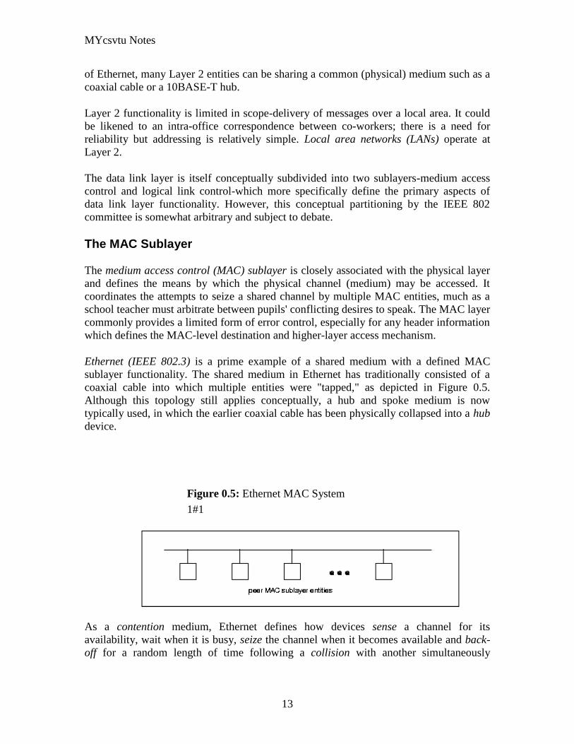
MYcsvtu Notes
13
of Ethernet many Layer 2 entities can be sharing a common (physical) medium such as a
coaxial cable or a 10BASE-T hub
Layer 2 functionality is limited in scope-delivery of messages over a local area It could
be likened to an intra-office correspondence between co-workers there is a need for
reliability but addressing is relatively simple Local area networks (LANs) operate at
Layer 2
The data link layer is itself conceptually subdivided into two sublayers-medium access
control and logical link control-which more specifically define the primary aspects of
data link layer functionality However this conceptual partitioning by the IEEE 802
committee is somewhat arbitrary and subject to debate
The MAC Sublayer
The medium access control (MAC) sublayer is closely associated with the physical layer
and defines the means by which the physical channel (medium) may be accessed It
coordinates the attempts to seize a shared channel by multiple MAC entities much as a
school teacher must arbitrate between pupils conflicting desires to speak The MAC layer
commonly provides a limited form of error control especially for any header information
which defines the MAC-level destination and higher-layer access mechanism
Ethernet (IEEE 8023) is a prime example of a shared medium with a defined MAC
sublayer functionality The shared medium in Ethernet has traditionally consisted of a
coaxial cable into which multiple entities were tapped as depicted in Figure 05
Although this topology still applies conceptually a hub and spoke medium is now
typically used in which the earlier coaxial cable has been physically collapsed into a hub
device
Figure 05 Ethernet MAC System
11
As a contention medium Ethernet defines how devices sense a channel for its
availability wait when it is busy seize the channel when it becomes available and back-
off for a random length of time following a collision with another simultaneously
MYcsvtu Notes
14
transmitting device On a shared channel such as Ethernet only a single entity can
transmit at a time or messages will be garbled
Not all shared channels involve contention A prime example of a contentionless shared
medium is token ring (IEEE 8025) in which control of the channel is rotated between
the devices sharing the channel in a deterministic round-robin manner Conceptually
control of the channel is given to the entity currently possessing a token If the device
has nothing to transmit it passes the token to the next device attached to the topological
ring depicted in Figure 06
Figure 06 Token Ring MAC System
11
IEEE-defined MAC sublayer addresses are six bytes long and permanently assigned to
each device typically called a network interface card orNIC The IEEE administers the
assignment of these addresses in blocks to manufacturers to assure the global uniqueness
that the MAC sublayer protocols rely on for plug Ocircn play network setup Each
manufacturer must assure individual device identifier uniqueness within their assigned
block
The LLC Sublayer
The logical link control (LLC) sublayer is responsible for reliable transfer of messages-
called frames or more formally link protocol data units (LPDUs)-between two directly-
connected Layer 2 entities Functions needed to support this reliable transfer include
framing (indicating where a Layer 2 message begins and ends) sequence control error
control and flow control
MYcsvtu Notes
15
The degree to which sequence error and flow control are provided by the LLC sublayer
is determined by whether the link protocol is connection-oriented or connectionless A
connectionless link protocol provides little if any support for these functions A
connection-oriented link might use a windowing technique for these functions in which
frames are individually numbered and acknowledged by their sequence number with
only a few such frames outstanding at any time
The connection-oriented functions of sequencing error and flow control provide a
foundation for services provided by higher layers As mentioned earlier not all layer or
sublayer functions are explicitly designed or implemented in any given system Provision
of these functions depends on the services required by higher layers
If the connection-oriented functions of the LLC sublayer are not implemented they must
be performed by higher layers for reliable end-to-end communication If these functions
are provided by several layers they might be somewhat redundant and add unnecessary
overhead (inefficiency) to the system In the worst case redundant provision of these
functions at multiple layers could serve cross purposes and actually degrade overall
system performance
An example of a connectionless LLC protocol is frame relay (T1617 618) which
defines point-to-point links with switches connecting individual links in a mesh topology
In a frame relay network endpoints are connected by a series of links and switches
Because frame relay is defined in terms of the links between frame relay access devices
(FRADs) and switches and between switches themselves it is an LLC protocol
Connectionless Layer 2 protocols are best suited for high quality transmission media
With high quality transmission media errors are rarely introduced in the transmission
between network layer entities and discovery of and recovery from errors is most
efficiently handled by the communicating hosts In this case it is better to move the
packets quickly across the traversed subnetworks from source to destination rather than
checking for errors at Layer 2
Frame relay is derived from the X25 (ISO 8208) protocol which spans Layers 2 and 3
X25 is a connection-oriented packet-switching technology which defines how
neighboring packet switches exchange data with one another in a reliable manner from
end-to-end Frame relay simply removes the connection-oriented functions of error and
sequence control however congestion control functions are provided in frame relay to
prevent the total traffic seen at any point in the network from overwhelming it
Connection-oriented Layer 2 protocols are best suited for low quality transmission media
where it is more efficient and cost-effective to discover and recover from errors as they
occur on each hop than to rely on the communicating hosts to perform error recovery
functions With ever-increasing quality of transmission facilities and decreasing costs of
computation capability at hosts the need for connection-oriented network layer protocols
is diminishing However X25 remains popular outside of North America where it has
been tariffed at levels which encourage its use
MYcsvtu Notes
16
End-to-end communications may be via shared or dedicated facilities or circuits Shared
facilities involve the use of packet switching technology to carry messages from end-to-
end messages are subdivided as necessary into packets which share physical and logical
channels with packets from various sources to various destinations Packet switching is
almost universally used in data communications because it is more efficient for the bursty
nature of data traffic
On the other hand some applications require dedicated facilities from end-to-end because
they are isochronous (eg voice) or bandwidth-intensive (eg large file transfer) This
mode of end-to-end circuit dedication is called circuit switched communication Because
the facilities are dedicated to a single user this tends to be much more expensive than the
packet switched mode of communication But some applications need it-it is an economic
trade-off
Dedicated circuits are a rather extreme form of connection-oriented protocol requiring
the same setup and tear-down phases prior to and following communication If the circuit
setup and tear-down is statically arranged (ie out-of-band) it is referred to as a
permanent virtual circuit or PVC If the circuit is dynamically setup and torn-down in-
band it is referred to as a switched virtual circuit or SVC
Layer 3 - The Network Layer
The network layer defines the functions necessary to support data communication
between indirectly-connected entities It provides the capability of forwarding messages
from one Layer 3 entity to another until the final destination is reached
The network layer introduces another layer of abstraction to the data communications
model It moves messages-called packets or more formally network protocol data units
(NPDUs)-between communicating Layer 3 entities-called end systems nodes or hosts
Network layer functions include route determination or routing and forwarding of
packets to their final destinations
In order to forward a packet to its destination host routing information must be provided
to theintermediate systems (ISs) or routers responsible for forwarding packets to their
respective destinations This routing information includes the address of the destination
which is contained in each packet The next hop to be traversed by the packet is
determined primarily by this destination address We will talk more about addressing and
routing in Chapter 1
This packet forwarding and routing is accomplished independent of both the media and
transmission types used at any step along the way The unimportance of local topology to
the network layer is demonstrated by the common use of cloud diagrams to depict
networks as in Figure 07 Since the network layer is concerned with getting packets
across many local networks called subnetworks its title would be more accurate if it
were the Internetwork Layer
MYcsvtu Notes
17
Figure 07 Network Layer ``Cloud
Diagram
11
The network layer functionality is global in scope-delivery of messages over a wide area
It could be likened to the postal system in which correspondence is passed from location
to location until it eventually reaches the destination address on the envelope10
The
network layer is the domain of wide area networks (WANs)
In order for routers to know how (ie on which link) to forward packets they must have
some knowledge of network topology This knowledge may be complete or partial and is
dynamically created and maintained via routing protocols used by routers to share their
knowledge of network topology with each other Routing is essentially the reduction of
global internetwork topology to local hop-by-hop routing decisions made
independently by each router
As with Layer 2 Layer 3 protocols may be connection-oriented or connectionless A
connection-oriented Layer 3 protocol such as X25 (ISO 8208) operates more statically
The basic idea is that an end-to-end route (X25 virtual connection) is established from
the originating data terminal equipment (DTE) to data communications equipment
(DCE) from DCE to DCE through the network then from the last DCE to the
terminating DTE this is the call setup Packets are then transmitted via this prearranged
route with all packets following the same path through the network Finally the route is
torn down (release) and packets cease flowing
X25 operation is like a phone call because it is a phone call X25 Layer 3 operation
assumes that a reliable connection-oriented service is provided by Layer 2 (also defined
by the X25 standard) although it does provide flow control via sequence numbers
Connectionless Layer 3 protocols such as the ever popular internet protocol (IP)(RFC11
791 and 792) and its ISO counterpart connectionless network protocol (CLNP) (ISO
MYcsvtu Notes
18
8473) route packets dynamically There is no prearranged path which is followed by
subsequent packets flowing from one host to another Instead each packet is individually
routed through a routing mesh there is no reason to believe that sequential packets
flowing between hosts will follow the same path So sequence errors may be introduced
at Layer 3 which must be corrected by a higher layer entity
Connectionless data packets are commonly referred to as datagrams and the service
provided by connectionless Layer 3 protocols is referred to as datagram service Stateless
datagram service is simpler for Layer 3 entities than connection-oriented network layer
services Because there is no state information to maintain dynamic routing protocols can
be used If a router fails during the dialogue between two communicating hosts
neighboring routers will discover this via the routing protocols and find alternate routes
which bypass the failed router
There seems to be a fair amount of ambiguity between the network layer and the LLC
sublayer Both can provide connection-oriented or connectionless services to higher
layers To a large extent if Layer 3 is explicitly implemented there is no need for an
LLC sublayer The primary difference is in scope-LLC addresses and protocols are
oriented toward a more local environment whereas network layer addresses and protocols
are global in scope
Excellent references to routing and forwarding of data packets can be found in [PERL92]
and [STEN95]
Layer 4 - The Transport Layer
The transport layer is concerned with getting Layer 4 messages-called segments or more
formally transport protocol data units (TPDUs) -from source to destination in a reliable
manner The perspective of Layer 4 is of end-to-end communications rather than the hop-
by-hop perspective of Layer 3 Layer 4 assumes that packets can be moved from network
entity to network entity eventually getting to the final destination host How this is
accomplished is of no concern to Layer 4 functionality
Like other layers transport layer protocols can be either connection-oriented or
connectionless depending on the services required by higher layers A common
implementation of Layers 3 and 4 involves a connection-oriented transport layer protocol
running over a connectionless network layer protocol such as the ubiquitous TCPIP
protocol suite In this instance the communicating hosts maintain state information on
communications with each other to determine when and what to send This state
information defines the connection between the communicating Layer 4 entities
The general idea here is that two communicating hosts need not be concerned with the
topology of the internetwork which lies between them They only need to know the state
of their pairwise communication If part of the intervening internetwork cloud suffers a
failure the Layer 3 entities (routers) will deal with it and recover dynamically Aside
MYcsvtu Notes
19
from potential retransmission of any lost segments the hosts Layer 4 entries do not have
to be at all concerned with routing and recovery activities at Layer 3
In the IP protocol suite the primary connectionless Layer 4 protocol is the User
Datagram Protocol (UDP)(RFC 768) which is carried by IP the primary connection-
oriented protocol is the Transmission Control Protocol (TCP)(RFC 793) The ISO world
defines five classes of transport layer protocol beginning with Class 0 (TP-0) for
connectionless operation and range up to Class 4 (TP-4)(ISO 8073) for connection-
oriented operation
Layer 5 - The Session Layer
The session layer provides a control structure for communication between applications
on hosts The communication at layer 5 is called a session which defines the relative
timing of communications between the hosts applications Synchronization of
communicating applications comes into play when coordinated timing of corresponding
events at the endpoints is imperative such as in financial transactions
Remember layers define communication functions not implementations It is unlikely
that a session layer would be explicitly implemented as a stand-alone program although
its functions would be implemented somewhere Session layer functions depend on the
reliability of communications between the endpoints and session layer functions must
therefore be implemented above Layer 4
Layer 6 - The Presentation Layer
The presentation layer performs any necessary data transformations or formatting
required by the end applications Functions provided by the presentation layer include
data compression file formatting and encryption Common data formatting is important
because it allows the same application file to be accessed by the application running on
different computer platforms This book is itself the product of an application running on
different platforms with common files being modified via these different platforms
Abstract Syntax Notation (ASN1) is commonly used to specify data values in a way
which allows processors to communicate independent of their varying native integer
sizes bit orderings (big or little endian) character sets etc ASN1 is a transfer syntax a
presentation layer formatting which appears frequently in the CDPD specification for
unambiguous definition of network management accounting limited size messaging and
other functions
An example of ASN1 encoding from an accounting Traffic Matrix Segment in the
CDPD specification is the following
MYcsvtu Notes
20
TrafficType = INTEGER
registration (0)
deregistration (1)
ip(2)
clnp(3)
Layer 7 - The Application Layer
The application layer provides the services which directly support an application running
on a host These services are directly accessible by an application via common well-
known application program interfaces (APIs) which can actually occur at many layers
Examples of layer 7 services include FTP (file transfer protocol) Telnet and SNMP
(simple network management protocol) Most network management activities are based
on the services provided by layer 7 application entities which in turn rely on lower layer
services to be able to perform their functions
7 Application ECHO ENRP FTP Gopher HTTP NFS RTSP SIP SMTP SNMP
SSH Telnet Whois XMPP
6 Presentation XDR ASN1 SMB AFP NCP
5 Session ASAP TLS SSL ISO 8327 CCITT X225 RPC NetBIOS ASP
4 Transport TCP UDP RTP SCTP SPX ATP IL
3 Network IP ICMP IGMP IPX OSPF RIP IGRP EIGRP ARP RARP X25
2 Data Link Ethernet Token ring HDLC Frame relay ISDN ATM 80211 WiFi
FDDI PPP
1 Physical 10BASE-T 100BASE-T 1000BASE-T SONETSDH G709 T-
carrierE-carrier various 80211 physical layers
The TCPIP Reference Model
The TCPIP reference model is the network model used in the current Internet
architecture [19] It has its origins back in the 1960s with the grandfather of the Internet
the ARPANET This was a research network sponsored by the Department of Defense in
the United States The following were seen as major design goals
ability to connect multiple networks together seamlessly
ability for connections to remain intact as long as the source and destination
machines were functioning
MYcsvtu Notes
21
to be built on flexible architecture
The reference model was named after two of its main protocols TCP (Transmission
Control Protocol) [12] and IP (Internet Protocol)
They choose to build a packet-switched network based on a connectionless internetwork
layer
Figure 21 TCPIP Network Protocol
A detailed description of the reference model is beyond the scope of this document and
project The basic idea of the networking system is to allow one application on a host
computer to talk to another application on a different host computer
The application forms its request then passes the packet down to the lower layers which
add their own control information either a header or a footer onto the packet Finally the
packet reaches the physical layer and is transmitted through the cable onto the destination
host The packet then travels up through the different layers with each layer reading
deciphering and removing the header or footer that was attached by its counterpart on the
originating computer Finally the packet arrives at the application it was destined for
Even though technically each layer communicates with the layer above or below it the
process can be viewed as one layer talking to its partner on the host as figure 21 shows
The Host-to-Network Layer
The Host-to-Network layer interfaces the TCPIP protocol stack to the physical network
The TCPIP reference model does not specify in any great detail the operation of this
layer except that the host has to connect to the network using some protocol so it can
send IP packets over it
As it is not officially defined it varies from implementation to implementation with
vendors supplying their own version
MYcsvtu Notes
22
The Network Layer
The job of the network layer is to inject packets into any network and have them travel
independently to the destination The layer defines IP (Internet Protocol) for its official
packet format and protocol Packet routing is a major job of this protocol
The Transport Layer
The transport layer is the interface between the application layer and the complex
hardware of the network It is designed to allow peer entities on the source and
destination hosts to carry on conversations
Data may be user data or control data Two modes are available full-duplex and half
duplex In full-duplex operation both sides can transmit and receive data simultaneously
whereas in half duplex a side can only send or receive at one time
Interaction between the transport layer and the layers immediately above and below are
shown in figure 22 Any program running in the application layer has the ability to send
a message using TCP or UDP which are the two protocols defined for the transport layer
The application can communicate with the TCP or the UDP service whichever it
requires Both the TCP and UDP communicate with the Internet Protocol in the internet
layer In all cases communication is a two way process The applications can read and
write to the transport layer The diagram only shows two protocols in the transport layer
TTCP will also reside in this layer between the other two protocols and function in the
same manner
Figure 22 Interaction with Application Transport and Internet Layers
A message to be sent originates in the application layer This is then passed down onto
the appropriate protocol in the transport layer These protocols add a header to the
message for the corresponding transport layer in the destination machine for purposes of
reassembling the message The segment is then passed onto the internet layer where the
Internet Protocol adds a further header Finally the segment is passed onto the physical
MYcsvtu Notes
23
layer a header and a trailer are added at this stage Figure 23 shows the structure of the
final segment being sent
Figure 23 Transmitted Segment from TCPIP Network
The Application Layer
The original TCPIP specification described a number of different applications that fit
into the top layer of the protocol stack These applications include Telnet FTP SMTP
and DNS
Telnet is a program that supports the TELNET [13] protocol over TCP TELNET is a
general two-way communication protocol that can be used to connect to another host and
run applications on that host remotely
FTP (File Transfer Protocol) [14] is a protocol that was originally designed to promote
the sharing of files among computer users It shields the user from the variations of file
storage on different architectures and allows for a reliable and efficient transfer of data
SMTP (Simple Mail Transport Protocol) [15] is the protocol used to transport electronic
mail from one computer to another through a series of other computers along the route
DNS [10] (Domain Name System) resolves the numerical address of a network node into
its textual name or vice-versa It would translate wwwyahoocom to 2047117771 to
allow the routing protocols to find the host that the packet is destined for
What is a Topology
The physical topology of a network refers to the configuration of cables computers and
other peripherals Physical topology should not be confused with logical topology which
is the method used to pass information between workstations Logical topology was
discussed in the Protocol chapter
Main Types of Physical Topologies
The following sections discuss the physical topologies used in networks and other related
topics
Linear Bus
MYcsvtu Notes
24
Star
Star-Wired Ring
Tree
Considerations When Choosing a Topology
Summary Chart
Linear Bus
A linear bus topology consists of a main run of cable with a terminator at each end (See
fig 1) All nodes (file server workstations and peripherals) are connected to the linear
cable Ethernet and LocalTalk networks use a linear bus topology
Fig 1 Linear Bus topology
Advantages of a Linear Bus Topology
Easy to connect a computer or peripheral to a linear bus
Requires less cable length than a star topology
Disadvantages of a Linear Bus Topology
Entire network shuts down if there is a break in the main cable
Terminators are required at both ends of the backbone cable
Difficult to identify the problem if the entire network shuts down
Not meant to be used as a stand-alone solution in a large building
Star
A star topology is designed with each node (file server workstations and peripherals)
connected directly to a central network hub or concentrator (See fig 2)
Data on a star network passes through the hub or concentrator before continuing to its
destination The hub or concentrator manages and controls all functions of the network It
also acts as a repeater for the data flow This configuration is common with twisted pair
cable however it can also be used with coaxial cable or fiber optic cable
MYcsvtu Notes
25
Fig 2 Star topology
Advantages of a Star Topology
Easy to install and wire
No disruptions to the network then connecting or removing devices
Easy to detect faults and to remove parts
Disadvantages of a Star Topology
Requires more cable length than a linear topology
If the hub or concentrator fails nodes attached are disabled
More expensive than linear bus topologies because of the cost of the
concentrators
The protocols used with star configurations are usually Ethernet or LocalTalk Token
Ring uses a similar topology called the star-wired ring
Star-Wired Ring
A star-wired ring topology may appear (externally) to be the same as a star topology
Internally the MAU (multistation access unit) of a star-wired ring contains wiring that
allows information to pass from one device to another in a circle or ring (See fig 3) The
Token Ring protocol uses a star-wired ring topology
Tree
A tree topology combines characteristics of linear bus and star topologies It consists of
groups of star-configured workstations connected to a linear bus backbone cable (See fig
MYcsvtu Notes
26
4) Tree topologies allow for the expansion of an existing network and enable schools to
configure a network to meet their needs
Fig 4 Tree topology
Advantages of a Tree Topology
Point-to-point wiring for individual segments
Supported by several hardware and software venders
Disadvantages of a Tree Topology
Overall length of each segment is limited by the type of cabling used
If the backbone line breaks the entire segment goes down
More difficult to configure and wire than other topologies
5-4-3 Rule
A consideration in setting up a tree topology using Ethernet protocol is the 5-4-3 rule
One aspect of the Ethernet protocol requires that a signal sent out on the network cable
reach every part of the network within a specified length of time Each concentrator or
repeater that a signal goes through adds a small amount of time This leads to the rule that
between any two nodes on the network there can only be a maximum of 5 segments
connected through 4 repeatersconcentrators In addition only 3 of the segments may be
populated (trunk) segments if they are made of coaxial cable A populated segment is one
which has one or more nodes attached to it In Figure 4 the 5-4-3 rule is adhered to The
MYcsvtu Notes
27
furthest two nodes on the network have 4 segments and 3 repeatersconcentrators
between them
This rule does not apply to other network protocols or Ethernet networks where all fiber
optic cabling or a combination of a fiber backbone with UTP cabling is used If there is a
combination of fiber optic backbone and UTP cabling the rule is simply translated to 7-
6-5 rule
] Mesh
Full
Fully Connected The type of network topology in which each of the nodes of the network is
connected to each of the other nodes in the network with a point-to-point link ndash
this makes it possible for data to be simultaneously transmitted from any single
node to all of the other nodes
Note The physical fully connected mesh topology is generally too costly and
complex for practical networks although the topology is used when there are only
a small number of nodes to be interconnected[3]
Partial
Partially Connected The type of network topology in which some of the nodes of the network are
connected to more than one other node in the network with a point-to-point link ndash
this makes it possible to take advantage of some of the redundancy that is
provided by a physical fully connected mesh topology without the expense and
complexity required for a connection between every node in the network
Note In most practical networks that are based upon the physical partially
connected mesh topology all of the data that is transmitted between nodes in the
network takes the shortest path between nodes except in the case of a failure or
break in one of the links in which case the data takes an alternate path to the
destination ndash this implies that the nodes of the network possess some type of
logical routing algorithm to determine the correct path to use at any particular
time
[edit] Hybrid Network Topologies
The hybrid topology is a type of network topology that is composed of one or more
interconnections of two or more networks that are based upon different physical
topologies or a type of network topology that is composed of one or more
interconnections of two or more networks that are based upon the same physical
topology but where the physical topology of the network resulting from such an
interconnection does not meet the definition of the original physical topology of the
interconnected networks (eg the physical topology of a network that would result from
an interconnection of two or more networks that are based upon the physical star
topology might create a hybrid topology which resembles a mixture of the physical star
MYcsvtu Notes
28
and physical bus topologies or a mixture of the physical star and the physical tree
topologies depending upon how the individual networks are interconnected while the
physical topology of a network that would result from an interconnection of two or more
networks that are based upon the physical distributed bus network retains the topology of
a physical distributed bus network)
Star-Bus A type of network topology in which the central nodes of one or more individual
networks that are based upon the physical star topology are connected together
using a common bus network whose physical topology is based upon the
physical linear bus topology the endpoints of the common bus being terminated
with the characteristic impedance of the transmission medium where required ndash
eg two or more hubs connected to a common backbone with drop cables
through the port on the hub that is provided for that purpose (eg a properly
configured uplink port) would comprise the physical bus portion of the physical
star-bus topology while each of the individual hubs combined with the
individual nodes which are connected to them would comprise the physical star
portion of the physical star-bus topology
Star-of-Stars
Hierarchical Star A type of network topology that is composed of an interconnection of individual
networks that are based upon the physical star topology connected together in a
hierarchical fashion to form a more complex network ndash eg a top level central
node which is the hub of the top level physical star topology and to which other
second level central nodes are attached as the spoke nodes each of which in
turn may also become the central nodes of a third level physical star topology
Notes 1) The physical hierarchical star topology is not a combination of the physical
linear bus and the physical star topologies as cited in some texts as there is no
common linear bus within the topology although the top level hub which is the
beginning of the physical hierarchical star topology may be connected to the
backbone of another network such as a common carrier which is topologically
not considered to be a part of the local network ndash if the top level central node is
connected to a backbone that is considered to be a part of the local network then
the resulting network topology would be considered to be a hybrid topology that
is a mixture of the topology of the backbone network and the physical hierarchical
star topology
2) The physical hierarchical star topology is also sometimes incorrectly referred
to as a physical tree topology since its physical topology is hierarchical however
the physical hierarchical star topology does not have a structure that is determined
by a branching factor as is the case with the physical tree topology and therefore
nodes may be added to or removed from any node that is the hub of one of the
individual physical star topology networks within a network that is based upon the
physical hierarchical star topology
3) The physical hierarchical star topology is commonly used in outside plant
(OSP) cabling to connect various buildings to a central connection facility which
MYcsvtu Notes
29
may also house the demarcation point for the connection to the data transmission
facilities of a common carrier and in inside plant (ISP) cabling to connect
multiple wiring closets within a building to a common wiring closet within the
same building which is also generally where the main backbone or trunk that
connects to a larger network if any enters the building
Star-wired Ring A type of hybrid physical network topology that is a combination of the physical
star topology and the physical ring topology the physical star portion of the
topology consisting of a network in which each of the nodes of which the network
is composed are connected to a central node with a point-to-point link in a hub
and spoke fashion the central node being the hub and the nodes that are
attached to the central node being the spokes (eg a collection of point-to-point
links from the peripheral nodes that converge at a central node) in a fashion that is
identical to the physical star topology while the physical ring portion of the
topology consists of circuitry within the central node which routes the signals on
the network to each of the connected nodes sequentially in a circular fashion
Note In an 8025 Token Ring network the central node is called a Multistation
Access Unit (MAU)
Hybrid Mesh A type of hybrid physical network topology that is a combination of the physical
partially connected topology and one or more other physical topologies the mesh
portion of the topology consisting of redundant or alternate connections between
some of the nodes in the network ndash the physical hybrid mesh topology is
commonly used in networks which require a high degree of availability
Considerations When Choosing a Topology
Money A linear bus network may be the least expensive way to install a network
you do not have to purchase concentrators
Length of cable needed The linear bus network uses shorter lengths of cable
Future growth With a star topology expanding a network is easily done by
adding another concentrator
Cable type The most common cable in schools is unshielded twisted pair which
is most often used with star topologies
Summary Chart
Common Cable Common Protocol
Linear Bus Twisted Pair
Coaxial
Ethernet
LocalTalk
MYcsvtu Notes
30
Fiber
Star Twisted Pair
Fiber
Ethernet
LocalTalk
Star-Wired Ring Twisted Pair Token Ring
Tree
Twisted Pair
Coaxial
Fiber
Ethernet
Internet vs Web
The Internet and the World Wide Web are not synonymous the Internet is a collection of
interconnected computer networks linked by copper wires fiber-optic cables wireless
connections etc the Web is a collection of interconnected documents and other
resources linked by hyperlinks and URLs The World Wide Web is accessible via the
Internet as are many other services including e-mail file sharing and others described
below
The best way to define and distinguish between these terms is to understand the Internet
protocol suite This collection of protocols is organized into layers such that each layer
provides the foundation and the services required by the layer above In this conception
the term Internet refers to computer networks that all communicate with IP (Internet
protocol) and TCP (transfer control protocol) Once this networking structure is
established then other protocols can run ―on top These other protocols are sometimes
called services or applications Hypertext transfer protocol or HTTP is an application
layer protocol that links billions of files together into the World Wide Web
Common uses of the Internet
The World Wide Web
Through keyword-driven Internet research using search engines like Google
millions worldwide have easy instant access to a vast and diverse amount of
online information Compared to encyclopedias and traditional libraries the
World Wide Web has enabled a sudden and extreme decentralization of
information and data
Many individuals and some companies and groups have adopted the use of Web logs or
blogs which are largely used as easily-updatable online diaries Some commercial
organizations encourage staff to fill them with advice on their areas of specialization in
the hope that visitors will be impressed by the expert knowledge and free information
and be attracted to the corporation as a result One example of this practice is Microsoft
MYcsvtu Notes
31
whose product developers publish their personal blogs in order to pique the publics
interest in their work
For more information on the distinction between the World Wide Web and the Internet
itself mdash as in everyday use the two are sometimes confused mdash see Dark internet where
this is discussed in more detail
Remote access
The Internet allows computer users to connect to other computers and information stores
easily wherever they may be across the world They may do this with or without the use
of security authentication and encryption technologies depending on the requirements
This is encouraging new ways of working from home collaboration and information
sharing in many industries An accountant sitting at home can audit the books of a
company based in another country on a server situated in a third country that is remotely
maintained by IT specialists in a fourth These accounts could have been created by
home-working book-keepers in other remote locations based on information e-mailed to
them from offices all over the world Some of these things were possible before the
widespread use of the Internet but the cost of private leased lines would have made
many of them infeasible in practice
An office worker away from his desk perhaps the other side of the world on a business
trip or a holiday can open a remote desktop session into his normal office PC using a
secure Virtual Private Network (VPN) connection via the Internet This gives him
complete access to all his normal files and data including e-mail and other applications
while he is away
This concept is also referred to by some network security people as the Virtual Private
Nightmare because it extends the secure perimeter of a corporate network into its
employees homes this has been the source of some notable security breaches but also
provides security for the workers
Functions
File-sharing
Instant messaging
Internet fax
Search engine
World Wide Web
MYcsvtu Notes
32
Intranets
What are Intranets
bull Intranet is Intra+ Net so an Intranet is an internal or private Internet used strictly
within the confines of a company university or organization Inter means
between or among hence the difference between the Internet and an Intranet
Some formal definitions of Intranets
bull Brown amp Duguid ―Intranets help present and
circulate boundary objects
bull Choo Detlor amp Turnbull ―Intranetshellip support the creation sharing and use of
knowledge
bull Stenmark ―Intranets are organizationally
restricted
A technical definition
bull An Intranet is a network based on the internet TCPIP open standard An intranet
belongs to an organization and is designed to be accessible only by the
organizations members employees or others with authorization An intranets
Web site looks and act just like other Web sites but has a firewall surrounding it
to fend off unauthorized users
Design Of Intranets
Steps
bull Analyze the organizationlsquos information ecology
bull Identify the typical problems experienced by users
bull Analyze the information behaviors of these set of users
bull Create value added processes to resolve the problems of users and to improve the
Information Ecology
Value Added Processes
bull Intranets may be designed to improve the organizational information ecology
MYcsvtu Notes
33
bull Intranets provide a unified information space in which users can communicate
and collaborate with others
bull intranet applications and services may add value by supporting the organizationlsquos
knowledge creating and decision making process
Two Models of Online Environments
Centralized
Distributed
Centralized Environments
bull Before the web the centralized model was all we had (examples include
CompuServe Prodigy)
bull On the web centralized models include site-based services such as Yahoo
bull Most (all) college and university services are offered using the centralized
model
MYcsvtu Notes
34
bull But centralized environments are static inflexible expensive
Distributed Environments
bull The World Wide Web is an example of a distributed environment
bull Resources access are not centralized but scattered around the world
ndash Resources in the form of a network of connected (via DNS) web servers
ndash Access in the form of a network of connected (via DNS) internet service
providers
ndash Users in the form of individualized and connected (via HTTP) web
browsers
bull The big issue ndash integration ndash that is making different systems work together
Design Principles
Network Design Principles
ndash Specifies how networks differ from traditional learning
ndash The idea is that each principle confers an advantage over non-network
systems
ndash Can be used as a means of evaluating new technology
1 Decentralize
ndash Centralized networks have a characteristic starlsquo shape
bull Some entities have many connections
bull The vast majority have few
bull Eg broadcast network teacher in a classroom
ndash Decentralized networks form a mesh
bull The weight of connections flow is distributed
bull Balanced load = more stable
bull Foster connections between entities fill outlsquo the star
Distribute
ndash Network entities reside in different physical locations
bull Reduces risk of network failure
bull Reduces need for major infrastructure such as powerful servers
large bandwidth massive storage
ndash Examples
bull Peer-to-peer networks such as Kazaa Gnutella
bull Content syndication networks such as RSS
ndash Emphasis is on sharing not copying
bull Locallsquo copies are temporary
MYcsvtu Notes
35
Computer Graphics
Computer Graphics is about animation (films)
Games are very important in Computer Graphics
Medical Imaging is another driving force
Computer Aided Design too
Graphics Definitions
bull Point
ndash a location in space 2D or 3D
ndash sometimes denotes one pixel
bull Line
ndash straight path connecting two points
ndash infinitesimal width consistent density
ndash beginning and end on points
bull Vertex
ndash point in 3D
bull Edge
ndash line in 3D connecting two vertices
bull PolygonFaceFacet
ndash arbitrary shape formed by connected vertices
ndash fundamental unit of 3D computer graphics
bull Raster
ndash derived from TV systems for a row of pixels
ndash commonly referred to as a scanline
ndash does influence algorithms ndash reducing memory requirements parallelism
etc
ndash is the derivation of rasterization scan-line algorithms
Displays
bull Most desktop displays use a cathode ray tube (CRT) while portable computing
devices such as laptops incorporate liquid crystal display (LCD)
bull Because of their slimmer design and smaller energy consumption monitors using
LCD technologies are beginning to replace the venerable CRT on many desktops
Cathode-Ray Tubes
MYcsvtu Notes
36
bull Classical output device is a monitor
bull Cathode-Ray Tube (CRT)
ndash Invented by Karl Ferdinand Braun (1897)
ndash Beam of electrons directed from cathode (-)to phosphor-coated
(fluorescent) screen (anode (+))
ndash Directed by magnetic focusing and deflection coils (anodes) in vacuum
filled tube
ndash Phosphor emits photon of light when hit by an electron of varied
persistence (long 15-20 ms for texts short lt 1ms for animation)
ndash Refresh rate (50-60 Hz 72-76 Hz) to avoid flicker trail
ndash Phosphors are organic compounds characterized by their persistence and
their color (blue red green)
Cathode-Ray Tubes
bull Cathode-Ray Tube (CRT)
ndash Horizontal deflection and vertical deflection direct the electron beam to
any point on the screen
ndash Intensity knob regulates the flow of electrons by controlling the voltage at
the control grid (high voltage reduces the electron density and thus
brightness)
ndash Accelerating voltage from positive coating inside screen (anode screen) or
an accelerating anode
bull Image maintenance
ndash Charge distribution to store picture information
OR
ndash Refresh CRT refreshes the display constantly to maintain phosphor glow
Cathode-Ray Tubes
bullCathode-Ray Tube (CRT)
ndash Horizontal deflection and vertical deflection direct the electron beam to any point
on the screen
ndash Intensity knob regulates the flow of electrons by controlling the voltage at the
control grid (high voltage reduces the electron density and thus brightness)
ndash Accelerating voltage from positive coating inside screen (anode screen) or an
accelerating anode
bullImage maintenance
ndash Charge distribution to store picture information
OR
ndash Refresh CRT refreshes the display constantly to maintain phosphor glow
bull Characteristics of Cathode-Ray Tube (CRT)
MYcsvtu Notes
37
ndash Intensity is proportional to the number of electrons repelled in beam per
second (brightness)
ndash Resolution is the maximum number of points that can be displayed
without overlap is expressed as number of horizontal points by number of
vertical points points are called pixels (picture elements) example
resolution 1024 x 768 pixels Typical resolution is 1280 x 1024 pixels
bull High-definition systems high resolution systems
bull Focusing
ndash Focusing forces the electron beam to converge to a point on the monitor
screen
ndash Can be electrostatic (lens) or magnetic (field)
bull Deflection
ndash Deflection directs the electron beam horizontally andor vertically to any
point on the screen
ndash Can be controlled by electric (deflection plates slide 9) or magnetic fields
(deflection coils slide 5)
ndash Magnetic coils two pairs (topbottom leftright) of tube neck
ndash Electric plates two pairs (horizontal vertical)
Raster-scan Displays
bullVideo displays can be either raster-scan or random-scan displays
bullRaster-scan display is the most common type of monitor using a CRT
bullThe electron beam scans the screen from top to bottom one row at a time Each row is
called a scan line
bullThe electron beam is turned on and off to produce a collection of dots painted one row at
a time These will form the image
bullA raster is a matrix of pixels covering the screen area and is composed of raster lines
Raster-scan Displays
MYcsvtu Notes
38
Raster-scan Displays
bullThe image is stored in a frame buffer containing the total screen area and where each
memory location corresponds to a pixel
bullIn a monochrome system each bit is 1 or 0 for the corresponding pixel to be on or off
(bitmap)
bullThe display processor scans the frame buffer to turn electron beam onoff depending if
the bit is 1 or 0
bullFor color monitors the frame buffer also contains the color of each pixel (color buffer)
as well as other characteristics of the image (gray scale hellip) 8 bitspixel 0255
(pixmap)
bullDepth of the buffer area is the number of bits per pixel (bit planes) up to 24
bullExamples television panels printers PC monitors (99 of raster-scan)
Raster-scan Displays
bullRefresh rate 24 is a minimum to avoid flicker corresponding to 24 Hz (1 Hz = 1 refresh
per second)
bullCurrent raster-scan displays have a refresh rate of at least 60 frames (60 Hz) per second
up to 120 (120 Hz)
bullUses large memory 640x480 307200 bits 38 kB
bullRefresh procedure
MYcsvtu Notes
39
ndashHorizontal retrace ndash beam returns to left of screen
ndashVertical retrace ndash bean returns to top left corner of screen
ndashInterlaced refresh ndash display first even-numbered lines then odd-numbered lines
permits to see the image in half the time
useful for slow refresh rates (30 Hz shows as 60 Hz)
Random-scan Displays
bullRandom scan systems are also called vector stroke-writing or calligraphic displays
bullThe electron beam directly draws the picture in any specified order
bullA pen plotter is an example of such a system
bullPicture is stored in a display list refresh display file vector file or display program as a
set of line drawing commands
bullRefreshes by scanning the list 30 to 60 times per second
bullMore suited for line-drawing applications such as architecture and manufacturing
Random-scan Displays
bullAdvantages
ndashHigh resolution
ndashEasy animation
ndashRequires little memory
bullDisadvantages
ndashRequires intelligent electron beam (processor controlled)
ndashLimited screen density limited to simple line-based images
ndashLimited color capability
bullImproved in the 1960lsquos by the Direct View Storage Tube (DVST) from Tektronix
Color CRT Monitor
Uses different phosphors a combination of Red Green and Blue to produce any color
Two methods
Random scan uses beam penetration
2 layers (Red Green) phosphors low speed electrons excite Red high speed electrons
excite Green interrmediate speed excite both to get yellow and orange Color is
controlled by electron beam voltage
Only produces a restricted set of colors
Raster scan uses a shadow mask with three electron guns Red Green and Blue (RGB
color model) Color is produced by adjusting the intensity level of each electron beam
Produces a wide range of colors from 8 to several millions
Raster scan
Most common as found in televisions
Beam scanned left to right flicked back to rescan from top to bottom then repeated
Repeated at 30Hz per frame sometimes higher to reduce flicker Interlacing scanning
MYcsvtu Notes
40
odd lines in whole screen then even lines is also used to reduce flicker Can also use
high-persistence phosphor to reduce flicker but causes image smearing especially with
significant animation
Resolution typically 512x512 but high-quality screens are available (and becoming more
common) at up to approximately 1600x1200 pixels Sun workstations have screens of
1192x980 pixels
Black amp white screens can display grayscale by varying the intensity of the electron
beam
Colour is achieved using three electron guns which hit red green or blue phosphors
Combining these colours can produce many others including white (all on) Phosphor
dots focused using a shadow mask - makes colour screens lower resolution than
monochrome
Alternative approach beam penetration Special phosphor glows a different colour
depending on intensity of beam
Colour or intensity at pixel held by computerlsquos video card 1 bitpixel can store offon
information hence only black ampwhite More bitspixel give rise to more colour
possibilities eg 8 bitspixel gives rise to 2^8=256 possible colours at any one time
Random Scan (Directed-beam refresh vector display)
Instead of scanning the whole display sequentially and horizontally the random scan
draws the lines to be displayed directly Screen update at gt30Hz to reduce flicker
Jaggies not found and higher resolutions possible (up to 4096x4096 pixels) Colour
achieved using beam penetration generally of poorer quality Eye strain and fatigue still
a problem and vector displays are more expensive
Direct view storage tube (DVST)
Used a lot in analogue storage oscilloscopes
Similar to random scan crt but image maintained by flood guns - no flicker Can be
incrementally updated but not selectively erased image has to be redrawn on completely
erased screen High resolution (typically 4096x3120 pixels) but low contrast low
brightness and difficulty in displaying colour
What is a Multimedia System
bull A system that involves
ndash generation
ndash representation
ndash storage
ndash transmission
ndash search and retrieval
ndash delivery
MYcsvtu Notes
41
of multimedia information
productionauthoring tools
compression and formats
file system design
networking issues
database management
server design streaming
Multimedia System Architecture
Information management subsystem Presentation Query
Storage subsystem Efficiently stored
amp retrieved
Network subsystem Delivery
Adaptation in Multimedia Systems
bull Multimedia systems can profit a lot from personalization
ndash User behavior
ndash User properties
bull Adaptation
ndash Models
ndash Mechanisms
Multimedia in a mobile environment
MYcsvtu Notes
42
bull Applications
ndash Emergency response systems mobile commerce phone service
entertainment games
What is Sound
A ripple is a pressure wave in water created by an object striking the water
Sound is a pressure wave in air created for example by an object such as a string
or our vocal cords vibrating Dark here represents more pressure light represents
less
MYcsvtu Notes
43
Sine Waves Form Pure Tones
This simple sound wave is a Sine Wave a Pure tone produced by a simple vibration
Sine Wave Sample Tone
This can be represented graphically as shown above
Converting Pressure into Voltage
The pressure wave of sound moves a diaphragm in the microphone which produces a
voltage proportional to the pressure of the sound wave at each instant
Animation
MYcsvtu Notes
44
bull Animation is the rapid display of a sequence of images of 2-D artwork or model
positions in order to create an illusion of movement It is an optical illusion of
motion due to the phenomenon of persistence of vision This could be anything
from a flip book to a motion picture film Animation deals with the generation
sequencing and display a set of images which is called frames to create an effect
of visual change or motion similar to a movie film
bull Animation is used in those instance where videography is not possible
Hardware Requirement For Animation
bull Image Generation Tools amp Devices
bull Computer monitors with image display Capability
Software Requirement For Animation
bull Animation creating software
bull Screen Capture Software
bull Animation Clips
bull Software support For High Resolution
bull Recording amp Playback Capability
bull Transition effect
Early animation
There is no single person that can be considered the creator of the art of animation as
there were several people doing several projects which could be considered various types
of animation all around the same time (Short hand-drawn animation scenes could be
presented with the Phenakistoscope the Zoetrope and other optical toys already in the
early 1800s)
The following is a brief listing on those who are often acknowledged as significant to the
development of animation Note that this list is by no means a comprehensive list of
contributors to early animation
Georges Meacuteliegraves was a creator of special effect films such as A Trip to the Moon He
used many techniques ndash one of which was to stop the camera rolling change something
in the scene and then continue rolling the film This is a very similar idea to that of stop-
motion animation Meacuteliegraves accidentally happened upon the technique when his camera
broke down while shooting a bus driving by When the camera was fixed a horse
happened to be passing by just as Meacuteliegraves continued to film The result was that the bus
appeared to change into a horse
MYcsvtu Notes
45
Fantasmagorie by Emile Cohl 1908
Eacutemile Cohl began drawing cartoon strips and created a film in 1908 called
Fantasmagorie The film largely consisted of a stick figure moving about and
encountering all manner of morphing objects such as a wine bottle that transforms into a
flower There were also sections of live action where the animatorlsquos hands would enter
the scene The film was created by drawing each frame on paper and then shooting each
frame onto negative film which gave the picture a blackboard look
Winsor McCay created detailed animations that required a team of artists and painstaking
attention for detail Each frame was drawn on paper requiring backgrounds to be
redrawn as well characters to be animated His films such as Gertie the Dinosaur (1914)
and The Sinking of the Lusitania (1918) were of an impressive scale although The
Sinking of the Lusitania used cels
In 1919 Otto Messmer created the character of Felix the cat for Pat Sullivans animation
studios The importance of Felix lies in the characters strong personality created largely
through gesture and actions
Animation techniques
Animation techniques are incredibly varied and difficult to categorize Techniques are
often related or combined The following is a brief on common types of animation
Again this list is by no means comprehensive
Traditional animation
An example of traditional animation a horse animated by rotoscoping from Edweard
Muybridges 19th century photos
Main article Traditional animation
MYcsvtu Notes
46
Also called cel animation the frames of a traditionally animated movie are hand-drawn
The drawings are traced or copied onto transparent acetate sheets called cels which are
then placed over a painted background and photographed one by one on a rostrum
camera Nowadays the use of cels (and cameras) is mostly obsolete since the drawings
are scanned into computers and digitally transferred directly to 35 mm film The look
of traditional cel animation is still preserved and the character animators work has
remained essentially the same over the past 70 years Because of the digital influence
over modern cel animation it is also known as tradigital animation
Examples The Lion King Spirited Away Les Triplettes de Belleville
Full animation The most common style in animation known for its realistic and often very detailed art
Examples All Disney feature length animated films The Secret of NIMH The Iron Giant
Limited animation A cheaper process of making animated cartoons that does not follow a realistic
approach
Examples The Flintstones Yellow Submarine
Rubber hose The characters are usually cartoony and the animators have a lot of artistic freedom as
rubber hose animations dont have to follow the laws of physics and anatomy in the same
degree as the other main styles in animation
Examples Early Mickey Mouse cartoons Ren and Stimpy Popeye
Rotoscoping A technique where animators trace live action movement frame by frame for use in
animated films
Examples Gullivers Travels American Pop
Stop motion
Stop-motion animation is any type of animation which requires the animator to physically
alter the scene shoot a frame again alter the scene and shoot a frame and so on to create
the animation There are many different types of stop-motion animation some noteable
examples are listed below
Clay animation
MYcsvtu Notes
47
A clay animation scene from a TV commercial
Often abbreviated to claymation this is a type of stop-motion animation using
figures made of clay or a similar malleable material The figures may have an
armature or wire frame inside of them similar to puppet animation (below)
Alternatively the figures may be made entirely of clay such as in the films of
Bruce Bickford where clay creatures morph into a variety of different shapes
Examples Wallace and Gromit Dimensions of Dialogue by Jan Švankmajer The
Amazing Mr Bickford The Trap Door
Cutout animation In this type of stop-motion animation the animation is formed by moving 2-
dimensional pieces of material such as paper or cloth
Examples the animated sequences of Monty Pythons Flying Circus (often
referred to as Dada animation named after the Dada art movement[citation needed]
)
Tale of Tales early episodes of South Park
Silhouette animation A type of cutout animation where the viewer only sees black silhouettes
Example The Adventures of Prince Achmed the worlds oldest surviving
animated feature film from 1926
Graphic animation
Model animation In this form of animation model animated characters interact with and are a part
of the live-action world
Examples The films of Ray Harryhausen (Jason and the Argonauts) and Willis
OBrien (King Kong)
Go motion
Object animation
Pixilation Examples Neighbours
Puppet animation Puppet animation typically involves puppet figures interacting with each other in
a constructed environment in contrast to the real-world interaction in model
MYcsvtu Notes
48
animation (above) The puppets generally have an armature inside of them to
keep them still and steady as well as constraining them to move at particular
joints
Examples The Nightmare Before Christmas Robot Chicken The Tale of the Fox
Brickfilm
Puppetoon
Computer animation
A short gif animation
Like stop motion computer animation encompasses a variety of techniques the unifying
idea being that the animation is created digitally on a computer
2D animation Figures are created andor edited on the computer using 2D bitmap graphics or
created and edited using 2D vector graphics This includes automated
computerized versions of traditional animation techniques such as of tweening
morphing onion skinning and interpolated rotoscoping
Examples A Scanner Darkly Jib Jab
Analog computer animation
Flash animation
PowerPoint animation
A completely synthetic computer-generated scene
3D animation
MYcsvtu Notes
49
Figures are created in the computer using polygons To allow these meshes to
move they are given a digital armature (sculpture) This process is called rigging
Various other techniques can be applied such as mathematical functions
(gravity) simulated fur or hair effects such as fire and water and the use of
motion capture to name but a few
Examples The Incredibles Shrek
Cel-shaded animation
Morph target animation
Skeletal animation
Motion capture
Crowd simulation
Less common techniques
Drawn on film animation A technique where footage is produced by creating the
images directly on film stock
Paint-on-glass animationA technique for making animated films by manipulating slow-
drying oil paints on sheets of glass
Pinscreen animation Makes use of a screen filled with movable pins which can be
moved in or out by pressing an object onto the screen The screen is lit from the side so
that the pins cast shadows The technique has been used to create animated films with a
range of textural effects difficult to achieve with traditional cel animation
Sand animation Sand is moved around on a backlighted or frontlighted piece of glass to
create each frame for an animated film
Multimedia
Multimedia (Lat Multum + Medium) is media that uses multiple forms of information
content and information processing (eg text audio graphics animation video
interactivity) to inform or entertain the (user) audience Multimedia also refers to the use
of (but not limited to) electronic media to store and experience multimedia content
Multimedia is similar to traditional mixed media in fine art but with a broader scope The
term rich media is synonymous for interactive multimedia
Categorization
Multimedia may be broadly divided into linear and non-linear categories Linear active
content progresses without any navigation control for the viewer such as a cinema
presentation Non-linear content offers user interactivity to control progress as used with
MYcsvtu Notes
50
a computer game or used in self-paced computer based training Non-linear content is
also known as hypermedia content
Multimedia presentations can be live or recorded A recorded presentation may allow
interactivity via a navigation system A live multimedia presentation may allow
interactivity via interaction with the presenter or performer
There are 2 basic way to represent some information
Unimedium Presentation
Multimedia Presentation
In case of computer system the commonly used medioa for the purpose of storage
access and transmission of information are
bull Text
bull Graphics
bull Animation
bull Audio
bull Video
Multimedia Computer System require
bull Faster CPU
bull Larger Storage Devices
bull Larger Main Memory
bull Good Graphics Terminal
bull IO devices required to play an audio associated with the program
Transmission Mode
bull Asynchronous
bull Synchronous
bull Isochronous
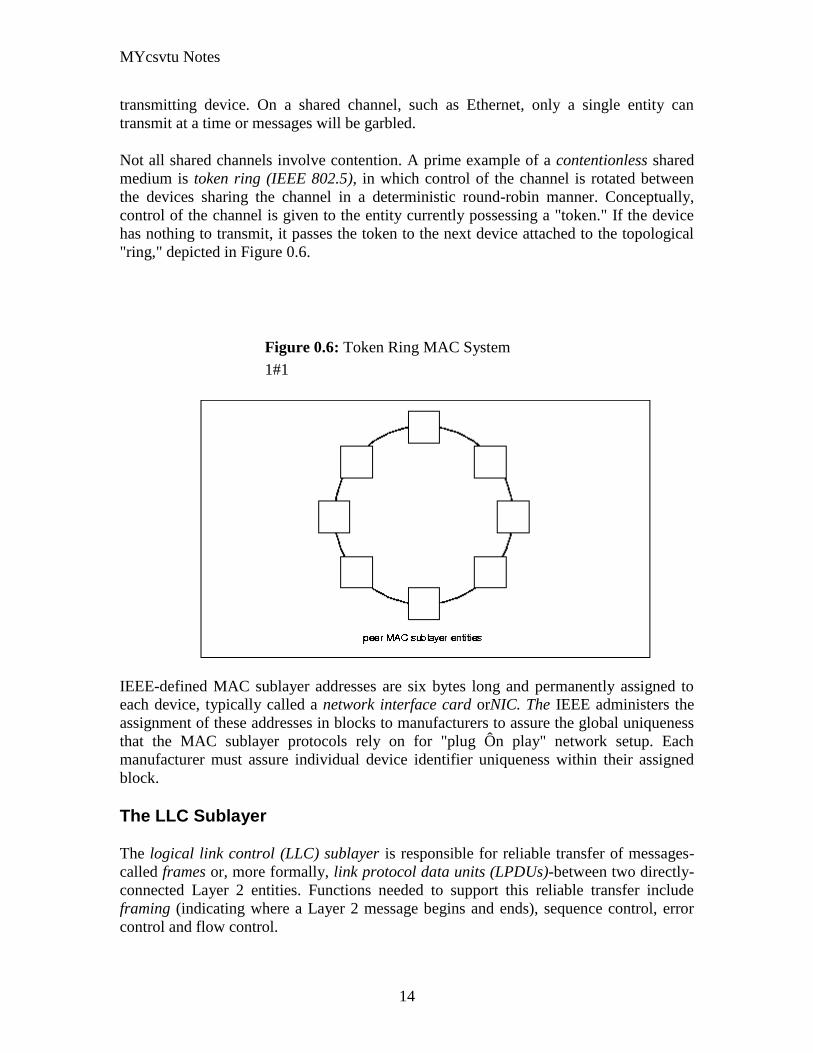
MYcsvtu Notes
14
transmitting device On a shared channel such as Ethernet only a single entity can
transmit at a time or messages will be garbled
Not all shared channels involve contention A prime example of a contentionless shared
medium is token ring (IEEE 8025) in which control of the channel is rotated between
the devices sharing the channel in a deterministic round-robin manner Conceptually
control of the channel is given to the entity currently possessing a token If the device
has nothing to transmit it passes the token to the next device attached to the topological
ring depicted in Figure 06
Figure 06 Token Ring MAC System
11
IEEE-defined MAC sublayer addresses are six bytes long and permanently assigned to
each device typically called a network interface card orNIC The IEEE administers the
assignment of these addresses in blocks to manufacturers to assure the global uniqueness
that the MAC sublayer protocols rely on for plug Ocircn play network setup Each
manufacturer must assure individual device identifier uniqueness within their assigned
block
The LLC Sublayer
The logical link control (LLC) sublayer is responsible for reliable transfer of messages-
called frames or more formally link protocol data units (LPDUs)-between two directly-
connected Layer 2 entities Functions needed to support this reliable transfer include
framing (indicating where a Layer 2 message begins and ends) sequence control error
control and flow control
MYcsvtu Notes
15
The degree to which sequence error and flow control are provided by the LLC sublayer
is determined by whether the link protocol is connection-oriented or connectionless A
connectionless link protocol provides little if any support for these functions A
connection-oriented link might use a windowing technique for these functions in which
frames are individually numbered and acknowledged by their sequence number with
only a few such frames outstanding at any time
The connection-oriented functions of sequencing error and flow control provide a
foundation for services provided by higher layers As mentioned earlier not all layer or
sublayer functions are explicitly designed or implemented in any given system Provision
of these functions depends on the services required by higher layers
If the connection-oriented functions of the LLC sublayer are not implemented they must
be performed by higher layers for reliable end-to-end communication If these functions
are provided by several layers they might be somewhat redundant and add unnecessary
overhead (inefficiency) to the system In the worst case redundant provision of these
functions at multiple layers could serve cross purposes and actually degrade overall
system performance
An example of a connectionless LLC protocol is frame relay (T1617 618) which
defines point-to-point links with switches connecting individual links in a mesh topology
In a frame relay network endpoints are connected by a series of links and switches
Because frame relay is defined in terms of the links between frame relay access devices
(FRADs) and switches and between switches themselves it is an LLC protocol
Connectionless Layer 2 protocols are best suited for high quality transmission media
With high quality transmission media errors are rarely introduced in the transmission
between network layer entities and discovery of and recovery from errors is most
efficiently handled by the communicating hosts In this case it is better to move the
packets quickly across the traversed subnetworks from source to destination rather than
checking for errors at Layer 2
Frame relay is derived from the X25 (ISO 8208) protocol which spans Layers 2 and 3
X25 is a connection-oriented packet-switching technology which defines how
neighboring packet switches exchange data with one another in a reliable manner from
end-to-end Frame relay simply removes the connection-oriented functions of error and
sequence control however congestion control functions are provided in frame relay to
prevent the total traffic seen at any point in the network from overwhelming it
Connection-oriented Layer 2 protocols are best suited for low quality transmission media
where it is more efficient and cost-effective to discover and recover from errors as they
occur on each hop than to rely on the communicating hosts to perform error recovery
functions With ever-increasing quality of transmission facilities and decreasing costs of
computation capability at hosts the need for connection-oriented network layer protocols
is diminishing However X25 remains popular outside of North America where it has
been tariffed at levels which encourage its use
MYcsvtu Notes
16
End-to-end communications may be via shared or dedicated facilities or circuits Shared
facilities involve the use of packet switching technology to carry messages from end-to-
end messages are subdivided as necessary into packets which share physical and logical
channels with packets from various sources to various destinations Packet switching is
almost universally used in data communications because it is more efficient for the bursty
nature of data traffic
On the other hand some applications require dedicated facilities from end-to-end because
they are isochronous (eg voice) or bandwidth-intensive (eg large file transfer) This
mode of end-to-end circuit dedication is called circuit switched communication Because
the facilities are dedicated to a single user this tends to be much more expensive than the
packet switched mode of communication But some applications need it-it is an economic
trade-off
Dedicated circuits are a rather extreme form of connection-oriented protocol requiring
the same setup and tear-down phases prior to and following communication If the circuit
setup and tear-down is statically arranged (ie out-of-band) it is referred to as a
permanent virtual circuit or PVC If the circuit is dynamically setup and torn-down in-
band it is referred to as a switched virtual circuit or SVC
Layer 3 - The Network Layer
The network layer defines the functions necessary to support data communication
between indirectly-connected entities It provides the capability of forwarding messages
from one Layer 3 entity to another until the final destination is reached
The network layer introduces another layer of abstraction to the data communications
model It moves messages-called packets or more formally network protocol data units
(NPDUs)-between communicating Layer 3 entities-called end systems nodes or hosts
Network layer functions include route determination or routing and forwarding of
packets to their final destinations
In order to forward a packet to its destination host routing information must be provided
to theintermediate systems (ISs) or routers responsible for forwarding packets to their
respective destinations This routing information includes the address of the destination
which is contained in each packet The next hop to be traversed by the packet is
determined primarily by this destination address We will talk more about addressing and
routing in Chapter 1
This packet forwarding and routing is accomplished independent of both the media and
transmission types used at any step along the way The unimportance of local topology to
the network layer is demonstrated by the common use of cloud diagrams to depict
networks as in Figure 07 Since the network layer is concerned with getting packets
across many local networks called subnetworks its title would be more accurate if it
were the Internetwork Layer
MYcsvtu Notes
17
Figure 07 Network Layer ``Cloud
Diagram
11
The network layer functionality is global in scope-delivery of messages over a wide area
It could be likened to the postal system in which correspondence is passed from location
to location until it eventually reaches the destination address on the envelope10
The
network layer is the domain of wide area networks (WANs)
In order for routers to know how (ie on which link) to forward packets they must have
some knowledge of network topology This knowledge may be complete or partial and is
dynamically created and maintained via routing protocols used by routers to share their
knowledge of network topology with each other Routing is essentially the reduction of
global internetwork topology to local hop-by-hop routing decisions made
independently by each router
As with Layer 2 Layer 3 protocols may be connection-oriented or connectionless A
connection-oriented Layer 3 protocol such as X25 (ISO 8208) operates more statically
The basic idea is that an end-to-end route (X25 virtual connection) is established from
the originating data terminal equipment (DTE) to data communications equipment
(DCE) from DCE to DCE through the network then from the last DCE to the
terminating DTE this is the call setup Packets are then transmitted via this prearranged
route with all packets following the same path through the network Finally the route is
torn down (release) and packets cease flowing
X25 operation is like a phone call because it is a phone call X25 Layer 3 operation
assumes that a reliable connection-oriented service is provided by Layer 2 (also defined
by the X25 standard) although it does provide flow control via sequence numbers
Connectionless Layer 3 protocols such as the ever popular internet protocol (IP)(RFC11
791 and 792) and its ISO counterpart connectionless network protocol (CLNP) (ISO
MYcsvtu Notes
18
8473) route packets dynamically There is no prearranged path which is followed by
subsequent packets flowing from one host to another Instead each packet is individually
routed through a routing mesh there is no reason to believe that sequential packets
flowing between hosts will follow the same path So sequence errors may be introduced
at Layer 3 which must be corrected by a higher layer entity
Connectionless data packets are commonly referred to as datagrams and the service
provided by connectionless Layer 3 protocols is referred to as datagram service Stateless
datagram service is simpler for Layer 3 entities than connection-oriented network layer
services Because there is no state information to maintain dynamic routing protocols can
be used If a router fails during the dialogue between two communicating hosts
neighboring routers will discover this via the routing protocols and find alternate routes
which bypass the failed router
There seems to be a fair amount of ambiguity between the network layer and the LLC
sublayer Both can provide connection-oriented or connectionless services to higher
layers To a large extent if Layer 3 is explicitly implemented there is no need for an
LLC sublayer The primary difference is in scope-LLC addresses and protocols are
oriented toward a more local environment whereas network layer addresses and protocols
are global in scope
Excellent references to routing and forwarding of data packets can be found in [PERL92]
and [STEN95]
Layer 4 - The Transport Layer
The transport layer is concerned with getting Layer 4 messages-called segments or more
formally transport protocol data units (TPDUs) -from source to destination in a reliable
manner The perspective of Layer 4 is of end-to-end communications rather than the hop-
by-hop perspective of Layer 3 Layer 4 assumes that packets can be moved from network
entity to network entity eventually getting to the final destination host How this is
accomplished is of no concern to Layer 4 functionality
Like other layers transport layer protocols can be either connection-oriented or
connectionless depending on the services required by higher layers A common
implementation of Layers 3 and 4 involves a connection-oriented transport layer protocol
running over a connectionless network layer protocol such as the ubiquitous TCPIP
protocol suite In this instance the communicating hosts maintain state information on
communications with each other to determine when and what to send This state
information defines the connection between the communicating Layer 4 entities
The general idea here is that two communicating hosts need not be concerned with the
topology of the internetwork which lies between them They only need to know the state
of their pairwise communication If part of the intervening internetwork cloud suffers a
failure the Layer 3 entities (routers) will deal with it and recover dynamically Aside
MYcsvtu Notes
19
from potential retransmission of any lost segments the hosts Layer 4 entries do not have
to be at all concerned with routing and recovery activities at Layer 3
In the IP protocol suite the primary connectionless Layer 4 protocol is the User
Datagram Protocol (UDP)(RFC 768) which is carried by IP the primary connection-
oriented protocol is the Transmission Control Protocol (TCP)(RFC 793) The ISO world
defines five classes of transport layer protocol beginning with Class 0 (TP-0) for
connectionless operation and range up to Class 4 (TP-4)(ISO 8073) for connection-
oriented operation
Layer 5 - The Session Layer
The session layer provides a control structure for communication between applications
on hosts The communication at layer 5 is called a session which defines the relative
timing of communications between the hosts applications Synchronization of
communicating applications comes into play when coordinated timing of corresponding
events at the endpoints is imperative such as in financial transactions
Remember layers define communication functions not implementations It is unlikely
that a session layer would be explicitly implemented as a stand-alone program although
its functions would be implemented somewhere Session layer functions depend on the
reliability of communications between the endpoints and session layer functions must
therefore be implemented above Layer 4
Layer 6 - The Presentation Layer
The presentation layer performs any necessary data transformations or formatting
required by the end applications Functions provided by the presentation layer include
data compression file formatting and encryption Common data formatting is important
because it allows the same application file to be accessed by the application running on
different computer platforms This book is itself the product of an application running on
different platforms with common files being modified via these different platforms
Abstract Syntax Notation (ASN1) is commonly used to specify data values in a way
which allows processors to communicate independent of their varying native integer
sizes bit orderings (big or little endian) character sets etc ASN1 is a transfer syntax a
presentation layer formatting which appears frequently in the CDPD specification for
unambiguous definition of network management accounting limited size messaging and
other functions
An example of ASN1 encoding from an accounting Traffic Matrix Segment in the
CDPD specification is the following
MYcsvtu Notes
20
TrafficType = INTEGER
registration (0)
deregistration (1)
ip(2)
clnp(3)
Layer 7 - The Application Layer
The application layer provides the services which directly support an application running
on a host These services are directly accessible by an application via common well-
known application program interfaces (APIs) which can actually occur at many layers
Examples of layer 7 services include FTP (file transfer protocol) Telnet and SNMP
(simple network management protocol) Most network management activities are based
on the services provided by layer 7 application entities which in turn rely on lower layer
services to be able to perform their functions
7 Application ECHO ENRP FTP Gopher HTTP NFS RTSP SIP SMTP SNMP
SSH Telnet Whois XMPP
6 Presentation XDR ASN1 SMB AFP NCP
5 Session ASAP TLS SSL ISO 8327 CCITT X225 RPC NetBIOS ASP
4 Transport TCP UDP RTP SCTP SPX ATP IL
3 Network IP ICMP IGMP IPX OSPF RIP IGRP EIGRP ARP RARP X25
2 Data Link Ethernet Token ring HDLC Frame relay ISDN ATM 80211 WiFi
FDDI PPP
1 Physical 10BASE-T 100BASE-T 1000BASE-T SONETSDH G709 T-
carrierE-carrier various 80211 physical layers
The TCPIP Reference Model
The TCPIP reference model is the network model used in the current Internet
architecture [19] It has its origins back in the 1960s with the grandfather of the Internet
the ARPANET This was a research network sponsored by the Department of Defense in
the United States The following were seen as major design goals
ability to connect multiple networks together seamlessly
ability for connections to remain intact as long as the source and destination
machines were functioning
MYcsvtu Notes
21
to be built on flexible architecture
The reference model was named after two of its main protocols TCP (Transmission
Control Protocol) [12] and IP (Internet Protocol)
They choose to build a packet-switched network based on a connectionless internetwork
layer
Figure 21 TCPIP Network Protocol
A detailed description of the reference model is beyond the scope of this document and
project The basic idea of the networking system is to allow one application on a host
computer to talk to another application on a different host computer
The application forms its request then passes the packet down to the lower layers which
add their own control information either a header or a footer onto the packet Finally the
packet reaches the physical layer and is transmitted through the cable onto the destination
host The packet then travels up through the different layers with each layer reading
deciphering and removing the header or footer that was attached by its counterpart on the
originating computer Finally the packet arrives at the application it was destined for
Even though technically each layer communicates with the layer above or below it the
process can be viewed as one layer talking to its partner on the host as figure 21 shows
The Host-to-Network Layer
The Host-to-Network layer interfaces the TCPIP protocol stack to the physical network
The TCPIP reference model does not specify in any great detail the operation of this
layer except that the host has to connect to the network using some protocol so it can
send IP packets over it
As it is not officially defined it varies from implementation to implementation with
vendors supplying their own version
MYcsvtu Notes
22
The Network Layer
The job of the network layer is to inject packets into any network and have them travel
independently to the destination The layer defines IP (Internet Protocol) for its official
packet format and protocol Packet routing is a major job of this protocol
The Transport Layer
The transport layer is the interface between the application layer and the complex
hardware of the network It is designed to allow peer entities on the source and
destination hosts to carry on conversations
Data may be user data or control data Two modes are available full-duplex and half
duplex In full-duplex operation both sides can transmit and receive data simultaneously
whereas in half duplex a side can only send or receive at one time
Interaction between the transport layer and the layers immediately above and below are
shown in figure 22 Any program running in the application layer has the ability to send
a message using TCP or UDP which are the two protocols defined for the transport layer
The application can communicate with the TCP or the UDP service whichever it
requires Both the TCP and UDP communicate with the Internet Protocol in the internet
layer In all cases communication is a two way process The applications can read and
write to the transport layer The diagram only shows two protocols in the transport layer
TTCP will also reside in this layer between the other two protocols and function in the
same manner
Figure 22 Interaction with Application Transport and Internet Layers
A message to be sent originates in the application layer This is then passed down onto
the appropriate protocol in the transport layer These protocols add a header to the
message for the corresponding transport layer in the destination machine for purposes of
reassembling the message The segment is then passed onto the internet layer where the
Internet Protocol adds a further header Finally the segment is passed onto the physical
MYcsvtu Notes
23
layer a header and a trailer are added at this stage Figure 23 shows the structure of the
final segment being sent
Figure 23 Transmitted Segment from TCPIP Network
The Application Layer
The original TCPIP specification described a number of different applications that fit
into the top layer of the protocol stack These applications include Telnet FTP SMTP
and DNS
Telnet is a program that supports the TELNET [13] protocol over TCP TELNET is a
general two-way communication protocol that can be used to connect to another host and
run applications on that host remotely
FTP (File Transfer Protocol) [14] is a protocol that was originally designed to promote
the sharing of files among computer users It shields the user from the variations of file
storage on different architectures and allows for a reliable and efficient transfer of data
SMTP (Simple Mail Transport Protocol) [15] is the protocol used to transport electronic
mail from one computer to another through a series of other computers along the route
DNS [10] (Domain Name System) resolves the numerical address of a network node into
its textual name or vice-versa It would translate wwwyahoocom to 2047117771 to
allow the routing protocols to find the host that the packet is destined for
What is a Topology
The physical topology of a network refers to the configuration of cables computers and
other peripherals Physical topology should not be confused with logical topology which
is the method used to pass information between workstations Logical topology was
discussed in the Protocol chapter
Main Types of Physical Topologies
The following sections discuss the physical topologies used in networks and other related
topics
Linear Bus
MYcsvtu Notes
24
Star
Star-Wired Ring
Tree
Considerations When Choosing a Topology
Summary Chart
Linear Bus
A linear bus topology consists of a main run of cable with a terminator at each end (See
fig 1) All nodes (file server workstations and peripherals) are connected to the linear
cable Ethernet and LocalTalk networks use a linear bus topology
Fig 1 Linear Bus topology
Advantages of a Linear Bus Topology
Easy to connect a computer or peripheral to a linear bus
Requires less cable length than a star topology
Disadvantages of a Linear Bus Topology
Entire network shuts down if there is a break in the main cable
Terminators are required at both ends of the backbone cable
Difficult to identify the problem if the entire network shuts down
Not meant to be used as a stand-alone solution in a large building
Star
A star topology is designed with each node (file server workstations and peripherals)
connected directly to a central network hub or concentrator (See fig 2)
Data on a star network passes through the hub or concentrator before continuing to its
destination The hub or concentrator manages and controls all functions of the network It
also acts as a repeater for the data flow This configuration is common with twisted pair
cable however it can also be used with coaxial cable or fiber optic cable
MYcsvtu Notes
25
Fig 2 Star topology
Advantages of a Star Topology
Easy to install and wire
No disruptions to the network then connecting or removing devices
Easy to detect faults and to remove parts
Disadvantages of a Star Topology
Requires more cable length than a linear topology
If the hub or concentrator fails nodes attached are disabled
More expensive than linear bus topologies because of the cost of the
concentrators
The protocols used with star configurations are usually Ethernet or LocalTalk Token
Ring uses a similar topology called the star-wired ring
Star-Wired Ring
A star-wired ring topology may appear (externally) to be the same as a star topology
Internally the MAU (multistation access unit) of a star-wired ring contains wiring that
allows information to pass from one device to another in a circle or ring (See fig 3) The
Token Ring protocol uses a star-wired ring topology
Tree
A tree topology combines characteristics of linear bus and star topologies It consists of
groups of star-configured workstations connected to a linear bus backbone cable (See fig
MYcsvtu Notes
26
4) Tree topologies allow for the expansion of an existing network and enable schools to
configure a network to meet their needs
Fig 4 Tree topology
Advantages of a Tree Topology
Point-to-point wiring for individual segments
Supported by several hardware and software venders
Disadvantages of a Tree Topology
Overall length of each segment is limited by the type of cabling used
If the backbone line breaks the entire segment goes down
More difficult to configure and wire than other topologies
5-4-3 Rule
A consideration in setting up a tree topology using Ethernet protocol is the 5-4-3 rule
One aspect of the Ethernet protocol requires that a signal sent out on the network cable
reach every part of the network within a specified length of time Each concentrator or
repeater that a signal goes through adds a small amount of time This leads to the rule that
between any two nodes on the network there can only be a maximum of 5 segments
connected through 4 repeatersconcentrators In addition only 3 of the segments may be
populated (trunk) segments if they are made of coaxial cable A populated segment is one
which has one or more nodes attached to it In Figure 4 the 5-4-3 rule is adhered to The
MYcsvtu Notes
27
furthest two nodes on the network have 4 segments and 3 repeatersconcentrators
between them
This rule does not apply to other network protocols or Ethernet networks where all fiber
optic cabling or a combination of a fiber backbone with UTP cabling is used If there is a
combination of fiber optic backbone and UTP cabling the rule is simply translated to 7-
6-5 rule
] Mesh
Full
Fully Connected The type of network topology in which each of the nodes of the network is
connected to each of the other nodes in the network with a point-to-point link ndash
this makes it possible for data to be simultaneously transmitted from any single
node to all of the other nodes
Note The physical fully connected mesh topology is generally too costly and
complex for practical networks although the topology is used when there are only
a small number of nodes to be interconnected[3]
Partial
Partially Connected The type of network topology in which some of the nodes of the network are
connected to more than one other node in the network with a point-to-point link ndash
this makes it possible to take advantage of some of the redundancy that is
provided by a physical fully connected mesh topology without the expense and
complexity required for a connection between every node in the network
Note In most practical networks that are based upon the physical partially
connected mesh topology all of the data that is transmitted between nodes in the
network takes the shortest path between nodes except in the case of a failure or
break in one of the links in which case the data takes an alternate path to the
destination ndash this implies that the nodes of the network possess some type of
logical routing algorithm to determine the correct path to use at any particular
time
[edit] Hybrid Network Topologies
The hybrid topology is a type of network topology that is composed of one or more
interconnections of two or more networks that are based upon different physical
topologies or a type of network topology that is composed of one or more
interconnections of two or more networks that are based upon the same physical
topology but where the physical topology of the network resulting from such an
interconnection does not meet the definition of the original physical topology of the
interconnected networks (eg the physical topology of a network that would result from
an interconnection of two or more networks that are based upon the physical star
topology might create a hybrid topology which resembles a mixture of the physical star
MYcsvtu Notes
28
and physical bus topologies or a mixture of the physical star and the physical tree
topologies depending upon how the individual networks are interconnected while the
physical topology of a network that would result from an interconnection of two or more
networks that are based upon the physical distributed bus network retains the topology of
a physical distributed bus network)
Star-Bus A type of network topology in which the central nodes of one or more individual
networks that are based upon the physical star topology are connected together
using a common bus network whose physical topology is based upon the
physical linear bus topology the endpoints of the common bus being terminated
with the characteristic impedance of the transmission medium where required ndash
eg two or more hubs connected to a common backbone with drop cables
through the port on the hub that is provided for that purpose (eg a properly
configured uplink port) would comprise the physical bus portion of the physical
star-bus topology while each of the individual hubs combined with the
individual nodes which are connected to them would comprise the physical star
portion of the physical star-bus topology
Star-of-Stars
Hierarchical Star A type of network topology that is composed of an interconnection of individual
networks that are based upon the physical star topology connected together in a
hierarchical fashion to form a more complex network ndash eg a top level central
node which is the hub of the top level physical star topology and to which other
second level central nodes are attached as the spoke nodes each of which in
turn may also become the central nodes of a third level physical star topology
Notes 1) The physical hierarchical star topology is not a combination of the physical
linear bus and the physical star topologies as cited in some texts as there is no
common linear bus within the topology although the top level hub which is the
beginning of the physical hierarchical star topology may be connected to the
backbone of another network such as a common carrier which is topologically
not considered to be a part of the local network ndash if the top level central node is
connected to a backbone that is considered to be a part of the local network then
the resulting network topology would be considered to be a hybrid topology that
is a mixture of the topology of the backbone network and the physical hierarchical
star topology
2) The physical hierarchical star topology is also sometimes incorrectly referred
to as a physical tree topology since its physical topology is hierarchical however
the physical hierarchical star topology does not have a structure that is determined
by a branching factor as is the case with the physical tree topology and therefore
nodes may be added to or removed from any node that is the hub of one of the
individual physical star topology networks within a network that is based upon the
physical hierarchical star topology
3) The physical hierarchical star topology is commonly used in outside plant
(OSP) cabling to connect various buildings to a central connection facility which
MYcsvtu Notes
29
may also house the demarcation point for the connection to the data transmission
facilities of a common carrier and in inside plant (ISP) cabling to connect
multiple wiring closets within a building to a common wiring closet within the
same building which is also generally where the main backbone or trunk that
connects to a larger network if any enters the building
Star-wired Ring A type of hybrid physical network topology that is a combination of the physical
star topology and the physical ring topology the physical star portion of the
topology consisting of a network in which each of the nodes of which the network
is composed are connected to a central node with a point-to-point link in a hub
and spoke fashion the central node being the hub and the nodes that are
attached to the central node being the spokes (eg a collection of point-to-point
links from the peripheral nodes that converge at a central node) in a fashion that is
identical to the physical star topology while the physical ring portion of the
topology consists of circuitry within the central node which routes the signals on
the network to each of the connected nodes sequentially in a circular fashion
Note In an 8025 Token Ring network the central node is called a Multistation
Access Unit (MAU)
Hybrid Mesh A type of hybrid physical network topology that is a combination of the physical
partially connected topology and one or more other physical topologies the mesh
portion of the topology consisting of redundant or alternate connections between
some of the nodes in the network ndash the physical hybrid mesh topology is
commonly used in networks which require a high degree of availability
Considerations When Choosing a Topology
Money A linear bus network may be the least expensive way to install a network
you do not have to purchase concentrators
Length of cable needed The linear bus network uses shorter lengths of cable
Future growth With a star topology expanding a network is easily done by
adding another concentrator
Cable type The most common cable in schools is unshielded twisted pair which
is most often used with star topologies
Summary Chart
Common Cable Common Protocol
Linear Bus Twisted Pair
Coaxial
Ethernet
LocalTalk
MYcsvtu Notes
30
Fiber
Star Twisted Pair
Fiber
Ethernet
LocalTalk
Star-Wired Ring Twisted Pair Token Ring
Tree
Twisted Pair
Coaxial
Fiber
Ethernet
Internet vs Web
The Internet and the World Wide Web are not synonymous the Internet is a collection of
interconnected computer networks linked by copper wires fiber-optic cables wireless
connections etc the Web is a collection of interconnected documents and other
resources linked by hyperlinks and URLs The World Wide Web is accessible via the
Internet as are many other services including e-mail file sharing and others described
below
The best way to define and distinguish between these terms is to understand the Internet
protocol suite This collection of protocols is organized into layers such that each layer
provides the foundation and the services required by the layer above In this conception
the term Internet refers to computer networks that all communicate with IP (Internet
protocol) and TCP (transfer control protocol) Once this networking structure is
established then other protocols can run ―on top These other protocols are sometimes
called services or applications Hypertext transfer protocol or HTTP is an application
layer protocol that links billions of files together into the World Wide Web
Common uses of the Internet
The World Wide Web
Through keyword-driven Internet research using search engines like Google
millions worldwide have easy instant access to a vast and diverse amount of
online information Compared to encyclopedias and traditional libraries the
World Wide Web has enabled a sudden and extreme decentralization of
information and data
Many individuals and some companies and groups have adopted the use of Web logs or
blogs which are largely used as easily-updatable online diaries Some commercial
organizations encourage staff to fill them with advice on their areas of specialization in
the hope that visitors will be impressed by the expert knowledge and free information
and be attracted to the corporation as a result One example of this practice is Microsoft
MYcsvtu Notes
31
whose product developers publish their personal blogs in order to pique the publics
interest in their work
For more information on the distinction between the World Wide Web and the Internet
itself mdash as in everyday use the two are sometimes confused mdash see Dark internet where
this is discussed in more detail
Remote access
The Internet allows computer users to connect to other computers and information stores
easily wherever they may be across the world They may do this with or without the use
of security authentication and encryption technologies depending on the requirements
This is encouraging new ways of working from home collaboration and information
sharing in many industries An accountant sitting at home can audit the books of a
company based in another country on a server situated in a third country that is remotely
maintained by IT specialists in a fourth These accounts could have been created by
home-working book-keepers in other remote locations based on information e-mailed to
them from offices all over the world Some of these things were possible before the
widespread use of the Internet but the cost of private leased lines would have made
many of them infeasible in practice
An office worker away from his desk perhaps the other side of the world on a business
trip or a holiday can open a remote desktop session into his normal office PC using a
secure Virtual Private Network (VPN) connection via the Internet This gives him
complete access to all his normal files and data including e-mail and other applications
while he is away
This concept is also referred to by some network security people as the Virtual Private
Nightmare because it extends the secure perimeter of a corporate network into its
employees homes this has been the source of some notable security breaches but also
provides security for the workers
Functions
File-sharing
Instant messaging
Internet fax
Search engine
World Wide Web
MYcsvtu Notes
32
Intranets
What are Intranets
bull Intranet is Intra+ Net so an Intranet is an internal or private Internet used strictly
within the confines of a company university or organization Inter means
between or among hence the difference between the Internet and an Intranet
Some formal definitions of Intranets
bull Brown amp Duguid ―Intranets help present and
circulate boundary objects
bull Choo Detlor amp Turnbull ―Intranetshellip support the creation sharing and use of
knowledge
bull Stenmark ―Intranets are organizationally
restricted
A technical definition
bull An Intranet is a network based on the internet TCPIP open standard An intranet
belongs to an organization and is designed to be accessible only by the
organizations members employees or others with authorization An intranets
Web site looks and act just like other Web sites but has a firewall surrounding it
to fend off unauthorized users
Design Of Intranets
Steps
bull Analyze the organizationlsquos information ecology
bull Identify the typical problems experienced by users
bull Analyze the information behaviors of these set of users
bull Create value added processes to resolve the problems of users and to improve the
Information Ecology
Value Added Processes
bull Intranets may be designed to improve the organizational information ecology
MYcsvtu Notes
33
bull Intranets provide a unified information space in which users can communicate
and collaborate with others
bull intranet applications and services may add value by supporting the organizationlsquos
knowledge creating and decision making process
Two Models of Online Environments
Centralized
Distributed
Centralized Environments
bull Before the web the centralized model was all we had (examples include
CompuServe Prodigy)
bull On the web centralized models include site-based services such as Yahoo
bull Most (all) college and university services are offered using the centralized
model
MYcsvtu Notes
34
bull But centralized environments are static inflexible expensive
Distributed Environments
bull The World Wide Web is an example of a distributed environment
bull Resources access are not centralized but scattered around the world
ndash Resources in the form of a network of connected (via DNS) web servers
ndash Access in the form of a network of connected (via DNS) internet service
providers
ndash Users in the form of individualized and connected (via HTTP) web
browsers
bull The big issue ndash integration ndash that is making different systems work together
Design Principles
Network Design Principles
ndash Specifies how networks differ from traditional learning
ndash The idea is that each principle confers an advantage over non-network
systems
ndash Can be used as a means of evaluating new technology
1 Decentralize
ndash Centralized networks have a characteristic starlsquo shape
bull Some entities have many connections
bull The vast majority have few
bull Eg broadcast network teacher in a classroom
ndash Decentralized networks form a mesh
bull The weight of connections flow is distributed
bull Balanced load = more stable
bull Foster connections between entities fill outlsquo the star
Distribute
ndash Network entities reside in different physical locations
bull Reduces risk of network failure
bull Reduces need for major infrastructure such as powerful servers
large bandwidth massive storage
ndash Examples
bull Peer-to-peer networks such as Kazaa Gnutella
bull Content syndication networks such as RSS
ndash Emphasis is on sharing not copying
bull Locallsquo copies are temporary
MYcsvtu Notes
35
Computer Graphics
Computer Graphics is about animation (films)
Games are very important in Computer Graphics
Medical Imaging is another driving force
Computer Aided Design too
Graphics Definitions
bull Point
ndash a location in space 2D or 3D
ndash sometimes denotes one pixel
bull Line
ndash straight path connecting two points
ndash infinitesimal width consistent density
ndash beginning and end on points
bull Vertex
ndash point in 3D
bull Edge
ndash line in 3D connecting two vertices
bull PolygonFaceFacet
ndash arbitrary shape formed by connected vertices
ndash fundamental unit of 3D computer graphics
bull Raster
ndash derived from TV systems for a row of pixels
ndash commonly referred to as a scanline
ndash does influence algorithms ndash reducing memory requirements parallelism
etc
ndash is the derivation of rasterization scan-line algorithms
Displays
bull Most desktop displays use a cathode ray tube (CRT) while portable computing
devices such as laptops incorporate liquid crystal display (LCD)
bull Because of their slimmer design and smaller energy consumption monitors using
LCD technologies are beginning to replace the venerable CRT on many desktops
Cathode-Ray Tubes
MYcsvtu Notes
36
bull Classical output device is a monitor
bull Cathode-Ray Tube (CRT)
ndash Invented by Karl Ferdinand Braun (1897)
ndash Beam of electrons directed from cathode (-)to phosphor-coated
(fluorescent) screen (anode (+))
ndash Directed by magnetic focusing and deflection coils (anodes) in vacuum
filled tube
ndash Phosphor emits photon of light when hit by an electron of varied
persistence (long 15-20 ms for texts short lt 1ms for animation)
ndash Refresh rate (50-60 Hz 72-76 Hz) to avoid flicker trail
ndash Phosphors are organic compounds characterized by their persistence and
their color (blue red green)
Cathode-Ray Tubes
bull Cathode-Ray Tube (CRT)
ndash Horizontal deflection and vertical deflection direct the electron beam to
any point on the screen
ndash Intensity knob regulates the flow of electrons by controlling the voltage at
the control grid (high voltage reduces the electron density and thus
brightness)
ndash Accelerating voltage from positive coating inside screen (anode screen) or
an accelerating anode
bull Image maintenance
ndash Charge distribution to store picture information
OR
ndash Refresh CRT refreshes the display constantly to maintain phosphor glow
Cathode-Ray Tubes
bullCathode-Ray Tube (CRT)
ndash Horizontal deflection and vertical deflection direct the electron beam to any point
on the screen
ndash Intensity knob regulates the flow of electrons by controlling the voltage at the
control grid (high voltage reduces the electron density and thus brightness)
ndash Accelerating voltage from positive coating inside screen (anode screen) or an
accelerating anode
bullImage maintenance
ndash Charge distribution to store picture information
OR
ndash Refresh CRT refreshes the display constantly to maintain phosphor glow
bull Characteristics of Cathode-Ray Tube (CRT)
MYcsvtu Notes
37
ndash Intensity is proportional to the number of electrons repelled in beam per
second (brightness)
ndash Resolution is the maximum number of points that can be displayed
without overlap is expressed as number of horizontal points by number of
vertical points points are called pixels (picture elements) example
resolution 1024 x 768 pixels Typical resolution is 1280 x 1024 pixels
bull High-definition systems high resolution systems
bull Focusing
ndash Focusing forces the electron beam to converge to a point on the monitor
screen
ndash Can be electrostatic (lens) or magnetic (field)
bull Deflection
ndash Deflection directs the electron beam horizontally andor vertically to any
point on the screen
ndash Can be controlled by electric (deflection plates slide 9) or magnetic fields
(deflection coils slide 5)
ndash Magnetic coils two pairs (topbottom leftright) of tube neck
ndash Electric plates two pairs (horizontal vertical)
Raster-scan Displays
bullVideo displays can be either raster-scan or random-scan displays
bullRaster-scan display is the most common type of monitor using a CRT
bullThe electron beam scans the screen from top to bottom one row at a time Each row is
called a scan line
bullThe electron beam is turned on and off to produce a collection of dots painted one row at
a time These will form the image
bullA raster is a matrix of pixels covering the screen area and is composed of raster lines
Raster-scan Displays
MYcsvtu Notes
38
Raster-scan Displays
bullThe image is stored in a frame buffer containing the total screen area and where each
memory location corresponds to a pixel
bullIn a monochrome system each bit is 1 or 0 for the corresponding pixel to be on or off
(bitmap)
bullThe display processor scans the frame buffer to turn electron beam onoff depending if
the bit is 1 or 0
bullFor color monitors the frame buffer also contains the color of each pixel (color buffer)
as well as other characteristics of the image (gray scale hellip) 8 bitspixel 0255
(pixmap)
bullDepth of the buffer area is the number of bits per pixel (bit planes) up to 24
bullExamples television panels printers PC monitors (99 of raster-scan)
Raster-scan Displays
bullRefresh rate 24 is a minimum to avoid flicker corresponding to 24 Hz (1 Hz = 1 refresh
per second)
bullCurrent raster-scan displays have a refresh rate of at least 60 frames (60 Hz) per second
up to 120 (120 Hz)
bullUses large memory 640x480 307200 bits 38 kB
bullRefresh procedure
MYcsvtu Notes
39
ndashHorizontal retrace ndash beam returns to left of screen
ndashVertical retrace ndash bean returns to top left corner of screen
ndashInterlaced refresh ndash display first even-numbered lines then odd-numbered lines
permits to see the image in half the time
useful for slow refresh rates (30 Hz shows as 60 Hz)
Random-scan Displays
bullRandom scan systems are also called vector stroke-writing or calligraphic displays
bullThe electron beam directly draws the picture in any specified order
bullA pen plotter is an example of such a system
bullPicture is stored in a display list refresh display file vector file or display program as a
set of line drawing commands
bullRefreshes by scanning the list 30 to 60 times per second
bullMore suited for line-drawing applications such as architecture and manufacturing
Random-scan Displays
bullAdvantages
ndashHigh resolution
ndashEasy animation
ndashRequires little memory
bullDisadvantages
ndashRequires intelligent electron beam (processor controlled)
ndashLimited screen density limited to simple line-based images
ndashLimited color capability
bullImproved in the 1960lsquos by the Direct View Storage Tube (DVST) from Tektronix
Color CRT Monitor
Uses different phosphors a combination of Red Green and Blue to produce any color
Two methods
Random scan uses beam penetration
2 layers (Red Green) phosphors low speed electrons excite Red high speed electrons
excite Green interrmediate speed excite both to get yellow and orange Color is
controlled by electron beam voltage
Only produces a restricted set of colors
Raster scan uses a shadow mask with three electron guns Red Green and Blue (RGB
color model) Color is produced by adjusting the intensity level of each electron beam
Produces a wide range of colors from 8 to several millions
Raster scan
Most common as found in televisions
Beam scanned left to right flicked back to rescan from top to bottom then repeated
Repeated at 30Hz per frame sometimes higher to reduce flicker Interlacing scanning
MYcsvtu Notes
40
odd lines in whole screen then even lines is also used to reduce flicker Can also use
high-persistence phosphor to reduce flicker but causes image smearing especially with
significant animation
Resolution typically 512x512 but high-quality screens are available (and becoming more
common) at up to approximately 1600x1200 pixels Sun workstations have screens of
1192x980 pixels
Black amp white screens can display grayscale by varying the intensity of the electron
beam
Colour is achieved using three electron guns which hit red green or blue phosphors
Combining these colours can produce many others including white (all on) Phosphor
dots focused using a shadow mask - makes colour screens lower resolution than
monochrome
Alternative approach beam penetration Special phosphor glows a different colour
depending on intensity of beam
Colour or intensity at pixel held by computerlsquos video card 1 bitpixel can store offon
information hence only black ampwhite More bitspixel give rise to more colour
possibilities eg 8 bitspixel gives rise to 2^8=256 possible colours at any one time
Random Scan (Directed-beam refresh vector display)
Instead of scanning the whole display sequentially and horizontally the random scan
draws the lines to be displayed directly Screen update at gt30Hz to reduce flicker
Jaggies not found and higher resolutions possible (up to 4096x4096 pixels) Colour
achieved using beam penetration generally of poorer quality Eye strain and fatigue still
a problem and vector displays are more expensive
Direct view storage tube (DVST)
Used a lot in analogue storage oscilloscopes
Similar to random scan crt but image maintained by flood guns - no flicker Can be
incrementally updated but not selectively erased image has to be redrawn on completely
erased screen High resolution (typically 4096x3120 pixels) but low contrast low
brightness and difficulty in displaying colour
What is a Multimedia System
bull A system that involves
ndash generation
ndash representation
ndash storage
ndash transmission
ndash search and retrieval
ndash delivery
MYcsvtu Notes
41
of multimedia information
productionauthoring tools
compression and formats
file system design
networking issues
database management
server design streaming
Multimedia System Architecture
Information management subsystem Presentation Query
Storage subsystem Efficiently stored
amp retrieved
Network subsystem Delivery
Adaptation in Multimedia Systems
bull Multimedia systems can profit a lot from personalization
ndash User behavior
ndash User properties
bull Adaptation
ndash Models
ndash Mechanisms
Multimedia in a mobile environment
MYcsvtu Notes
42
bull Applications
ndash Emergency response systems mobile commerce phone service
entertainment games
What is Sound
A ripple is a pressure wave in water created by an object striking the water
Sound is a pressure wave in air created for example by an object such as a string
or our vocal cords vibrating Dark here represents more pressure light represents
less
MYcsvtu Notes
43
Sine Waves Form Pure Tones
This simple sound wave is a Sine Wave a Pure tone produced by a simple vibration
Sine Wave Sample Tone
This can be represented graphically as shown above
Converting Pressure into Voltage
The pressure wave of sound moves a diaphragm in the microphone which produces a
voltage proportional to the pressure of the sound wave at each instant
Animation
MYcsvtu Notes
44
bull Animation is the rapid display of a sequence of images of 2-D artwork or model
positions in order to create an illusion of movement It is an optical illusion of
motion due to the phenomenon of persistence of vision This could be anything
from a flip book to a motion picture film Animation deals with the generation
sequencing and display a set of images which is called frames to create an effect
of visual change or motion similar to a movie film
bull Animation is used in those instance where videography is not possible
Hardware Requirement For Animation
bull Image Generation Tools amp Devices
bull Computer monitors with image display Capability
Software Requirement For Animation
bull Animation creating software
bull Screen Capture Software
bull Animation Clips
bull Software support For High Resolution
bull Recording amp Playback Capability
bull Transition effect
Early animation
There is no single person that can be considered the creator of the art of animation as
there were several people doing several projects which could be considered various types
of animation all around the same time (Short hand-drawn animation scenes could be
presented with the Phenakistoscope the Zoetrope and other optical toys already in the
early 1800s)
The following is a brief listing on those who are often acknowledged as significant to the
development of animation Note that this list is by no means a comprehensive list of
contributors to early animation
Georges Meacuteliegraves was a creator of special effect films such as A Trip to the Moon He
used many techniques ndash one of which was to stop the camera rolling change something
in the scene and then continue rolling the film This is a very similar idea to that of stop-
motion animation Meacuteliegraves accidentally happened upon the technique when his camera
broke down while shooting a bus driving by When the camera was fixed a horse
happened to be passing by just as Meacuteliegraves continued to film The result was that the bus
appeared to change into a horse
MYcsvtu Notes
45
Fantasmagorie by Emile Cohl 1908
Eacutemile Cohl began drawing cartoon strips and created a film in 1908 called
Fantasmagorie The film largely consisted of a stick figure moving about and
encountering all manner of morphing objects such as a wine bottle that transforms into a
flower There were also sections of live action where the animatorlsquos hands would enter
the scene The film was created by drawing each frame on paper and then shooting each
frame onto negative film which gave the picture a blackboard look
Winsor McCay created detailed animations that required a team of artists and painstaking
attention for detail Each frame was drawn on paper requiring backgrounds to be
redrawn as well characters to be animated His films such as Gertie the Dinosaur (1914)
and The Sinking of the Lusitania (1918) were of an impressive scale although The
Sinking of the Lusitania used cels
In 1919 Otto Messmer created the character of Felix the cat for Pat Sullivans animation
studios The importance of Felix lies in the characters strong personality created largely
through gesture and actions
Animation techniques
Animation techniques are incredibly varied and difficult to categorize Techniques are
often related or combined The following is a brief on common types of animation
Again this list is by no means comprehensive
Traditional animation
An example of traditional animation a horse animated by rotoscoping from Edweard
Muybridges 19th century photos
Main article Traditional animation
MYcsvtu Notes
46
Also called cel animation the frames of a traditionally animated movie are hand-drawn
The drawings are traced or copied onto transparent acetate sheets called cels which are
then placed over a painted background and photographed one by one on a rostrum
camera Nowadays the use of cels (and cameras) is mostly obsolete since the drawings
are scanned into computers and digitally transferred directly to 35 mm film The look
of traditional cel animation is still preserved and the character animators work has
remained essentially the same over the past 70 years Because of the digital influence
over modern cel animation it is also known as tradigital animation
Examples The Lion King Spirited Away Les Triplettes de Belleville
Full animation The most common style in animation known for its realistic and often very detailed art
Examples All Disney feature length animated films The Secret of NIMH The Iron Giant
Limited animation A cheaper process of making animated cartoons that does not follow a realistic
approach
Examples The Flintstones Yellow Submarine
Rubber hose The characters are usually cartoony and the animators have a lot of artistic freedom as
rubber hose animations dont have to follow the laws of physics and anatomy in the same
degree as the other main styles in animation
Examples Early Mickey Mouse cartoons Ren and Stimpy Popeye
Rotoscoping A technique where animators trace live action movement frame by frame for use in
animated films
Examples Gullivers Travels American Pop
Stop motion
Stop-motion animation is any type of animation which requires the animator to physically
alter the scene shoot a frame again alter the scene and shoot a frame and so on to create
the animation There are many different types of stop-motion animation some noteable
examples are listed below
Clay animation
MYcsvtu Notes
47
A clay animation scene from a TV commercial
Often abbreviated to claymation this is a type of stop-motion animation using
figures made of clay or a similar malleable material The figures may have an
armature or wire frame inside of them similar to puppet animation (below)
Alternatively the figures may be made entirely of clay such as in the films of
Bruce Bickford where clay creatures morph into a variety of different shapes
Examples Wallace and Gromit Dimensions of Dialogue by Jan Švankmajer The
Amazing Mr Bickford The Trap Door
Cutout animation In this type of stop-motion animation the animation is formed by moving 2-
dimensional pieces of material such as paper or cloth
Examples the animated sequences of Monty Pythons Flying Circus (often
referred to as Dada animation named after the Dada art movement[citation needed]
)
Tale of Tales early episodes of South Park
Silhouette animation A type of cutout animation where the viewer only sees black silhouettes
Example The Adventures of Prince Achmed the worlds oldest surviving
animated feature film from 1926
Graphic animation
Model animation In this form of animation model animated characters interact with and are a part
of the live-action world
Examples The films of Ray Harryhausen (Jason and the Argonauts) and Willis
OBrien (King Kong)
Go motion
Object animation
Pixilation Examples Neighbours
Puppet animation Puppet animation typically involves puppet figures interacting with each other in
a constructed environment in contrast to the real-world interaction in model
MYcsvtu Notes
48
animation (above) The puppets generally have an armature inside of them to
keep them still and steady as well as constraining them to move at particular
joints
Examples The Nightmare Before Christmas Robot Chicken The Tale of the Fox
Brickfilm
Puppetoon
Computer animation
A short gif animation
Like stop motion computer animation encompasses a variety of techniques the unifying
idea being that the animation is created digitally on a computer
2D animation Figures are created andor edited on the computer using 2D bitmap graphics or
created and edited using 2D vector graphics This includes automated
computerized versions of traditional animation techniques such as of tweening
morphing onion skinning and interpolated rotoscoping
Examples A Scanner Darkly Jib Jab
Analog computer animation
Flash animation
PowerPoint animation
A completely synthetic computer-generated scene
3D animation
MYcsvtu Notes
49
Figures are created in the computer using polygons To allow these meshes to
move they are given a digital armature (sculpture) This process is called rigging
Various other techniques can be applied such as mathematical functions
(gravity) simulated fur or hair effects such as fire and water and the use of
motion capture to name but a few
Examples The Incredibles Shrek
Cel-shaded animation
Morph target animation
Skeletal animation
Motion capture
Crowd simulation
Less common techniques
Drawn on film animation A technique where footage is produced by creating the
images directly on film stock
Paint-on-glass animationA technique for making animated films by manipulating slow-
drying oil paints on sheets of glass
Pinscreen animation Makes use of a screen filled with movable pins which can be
moved in or out by pressing an object onto the screen The screen is lit from the side so
that the pins cast shadows The technique has been used to create animated films with a
range of textural effects difficult to achieve with traditional cel animation
Sand animation Sand is moved around on a backlighted or frontlighted piece of glass to
create each frame for an animated film
Multimedia
Multimedia (Lat Multum + Medium) is media that uses multiple forms of information
content and information processing (eg text audio graphics animation video
interactivity) to inform or entertain the (user) audience Multimedia also refers to the use
of (but not limited to) electronic media to store and experience multimedia content
Multimedia is similar to traditional mixed media in fine art but with a broader scope The
term rich media is synonymous for interactive multimedia
Categorization
Multimedia may be broadly divided into linear and non-linear categories Linear active
content progresses without any navigation control for the viewer such as a cinema
presentation Non-linear content offers user interactivity to control progress as used with
MYcsvtu Notes
50
a computer game or used in self-paced computer based training Non-linear content is
also known as hypermedia content
Multimedia presentations can be live or recorded A recorded presentation may allow
interactivity via a navigation system A live multimedia presentation may allow
interactivity via interaction with the presenter or performer
There are 2 basic way to represent some information
Unimedium Presentation
Multimedia Presentation
In case of computer system the commonly used medioa for the purpose of storage
access and transmission of information are
bull Text
bull Graphics
bull Animation
bull Audio
bull Video
Multimedia Computer System require
bull Faster CPU
bull Larger Storage Devices
bull Larger Main Memory
bull Good Graphics Terminal
bull IO devices required to play an audio associated with the program
Transmission Mode
bull Asynchronous
bull Synchronous
bull Isochronous
MYcsvtu Notes
16
End-to-end communications may be via shared or dedicated facilities or circuits Shared
facilities involve the use of packet switching technology to carry messages from end-to-
end messages are subdivided as necessary into packets which share physical and logical
channels with packets from various sources to various destinations Packet switching is
almost universally used in data communications because it is more efficient for the bursty
nature of data traffic
On the other hand some applications require dedicated facilities from end-to-end because
they are isochronous (eg voice) or bandwidth-intensive (eg large file transfer) This
mode of end-to-end circuit dedication is called circuit switched communication Because
the facilities are dedicated to a single user this tends to be much more expensive than the
packet switched mode of communication But some applications need it-it is an economic
trade-off
Dedicated circuits are a rather extreme form of connection-oriented protocol requiring
the same setup and tear-down phases prior to and following communication If the circuit
setup and tear-down is statically arranged (ie out-of-band) it is referred to as a
permanent virtual circuit or PVC If the circuit is dynamically setup and torn-down in-
band it is referred to as a switched virtual circuit or SVC
Layer 3 - The Network Layer
The network layer defines the functions necessary to support data communication
between indirectly-connected entities It provides the capability of forwarding messages
from one Layer 3 entity to another until the final destination is reached
The network layer introduces another layer of abstraction to the data communications
model It moves messages-called packets or more formally network protocol data units
(NPDUs)-between communicating Layer 3 entities-called end systems nodes or hosts
Network layer functions include route determination or routing and forwarding of
packets to their final destinations
In order to forward a packet to its destination host routing information must be provided
to theintermediate systems (ISs) or routers responsible for forwarding packets to their
respective destinations This routing information includes the address of the destination
which is contained in each packet The next hop to be traversed by the packet is
determined primarily by this destination address We will talk more about addressing and
routing in Chapter 1
This packet forwarding and routing is accomplished independent of both the media and
transmission types used at any step along the way The unimportance of local topology to
the network layer is demonstrated by the common use of cloud diagrams to depict
networks as in Figure 07 Since the network layer is concerned with getting packets
across many local networks called subnetworks its title would be more accurate if it
were the Internetwork Layer
MYcsvtu Notes
17
Figure 07 Network Layer ``Cloud
Diagram
11
The network layer functionality is global in scope-delivery of messages over a wide area
It could be likened to the postal system in which correspondence is passed from location
to location until it eventually reaches the destination address on the envelope10
The
network layer is the domain of wide area networks (WANs)
In order for routers to know how (ie on which link) to forward packets they must have
some knowledge of network topology This knowledge may be complete or partial and is
dynamically created and maintained via routing protocols used by routers to share their
knowledge of network topology with each other Routing is essentially the reduction of
global internetwork topology to local hop-by-hop routing decisions made
independently by each router
As with Layer 2 Layer 3 protocols may be connection-oriented or connectionless A
connection-oriented Layer 3 protocol such as X25 (ISO 8208) operates more statically
The basic idea is that an end-to-end route (X25 virtual connection) is established from
the originating data terminal equipment (DTE) to data communications equipment
(DCE) from DCE to DCE through the network then from the last DCE to the
terminating DTE this is the call setup Packets are then transmitted via this prearranged
route with all packets following the same path through the network Finally the route is
torn down (release) and packets cease flowing
X25 operation is like a phone call because it is a phone call X25 Layer 3 operation
assumes that a reliable connection-oriented service is provided by Layer 2 (also defined
by the X25 standard) although it does provide flow control via sequence numbers
Connectionless Layer 3 protocols such as the ever popular internet protocol (IP)(RFC11
791 and 792) and its ISO counterpart connectionless network protocol (CLNP) (ISO
MYcsvtu Notes
18
8473) route packets dynamically There is no prearranged path which is followed by
subsequent packets flowing from one host to another Instead each packet is individually
routed through a routing mesh there is no reason to believe that sequential packets
flowing between hosts will follow the same path So sequence errors may be introduced
at Layer 3 which must be corrected by a higher layer entity
Connectionless data packets are commonly referred to as datagrams and the service
provided by connectionless Layer 3 protocols is referred to as datagram service Stateless
datagram service is simpler for Layer 3 entities than connection-oriented network layer
services Because there is no state information to maintain dynamic routing protocols can
be used If a router fails during the dialogue between two communicating hosts
neighboring routers will discover this via the routing protocols and find alternate routes
which bypass the failed router
There seems to be a fair amount of ambiguity between the network layer and the LLC
sublayer Both can provide connection-oriented or connectionless services to higher
layers To a large extent if Layer 3 is explicitly implemented there is no need for an
LLC sublayer The primary difference is in scope-LLC addresses and protocols are
oriented toward a more local environment whereas network layer addresses and protocols
are global in scope
Excellent references to routing and forwarding of data packets can be found in [PERL92]
and [STEN95]
Layer 4 - The Transport Layer
The transport layer is concerned with getting Layer 4 messages-called segments or more
formally transport protocol data units (TPDUs) -from source to destination in a reliable
manner The perspective of Layer 4 is of end-to-end communications rather than the hop-
by-hop perspective of Layer 3 Layer 4 assumes that packets can be moved from network
entity to network entity eventually getting to the final destination host How this is
accomplished is of no concern to Layer 4 functionality
Like other layers transport layer protocols can be either connection-oriented or
connectionless depending on the services required by higher layers A common
implementation of Layers 3 and 4 involves a connection-oriented transport layer protocol
running over a connectionless network layer protocol such as the ubiquitous TCPIP
protocol suite In this instance the communicating hosts maintain state information on
communications with each other to determine when and what to send This state
information defines the connection between the communicating Layer 4 entities
The general idea here is that two communicating hosts need not be concerned with the
topology of the internetwork which lies between them They only need to know the state
of their pairwise communication If part of the intervening internetwork cloud suffers a
failure the Layer 3 entities (routers) will deal with it and recover dynamically Aside
MYcsvtu Notes
19
from potential retransmission of any lost segments the hosts Layer 4 entries do not have
to be at all concerned with routing and recovery activities at Layer 3
In the IP protocol suite the primary connectionless Layer 4 protocol is the User
Datagram Protocol (UDP)(RFC 768) which is carried by IP the primary connection-
oriented protocol is the Transmission Control Protocol (TCP)(RFC 793) The ISO world
defines five classes of transport layer protocol beginning with Class 0 (TP-0) for
connectionless operation and range up to Class 4 (TP-4)(ISO 8073) for connection-
oriented operation
Layer 5 - The Session Layer
The session layer provides a control structure for communication between applications
on hosts The communication at layer 5 is called a session which defines the relative
timing of communications between the hosts applications Synchronization of
communicating applications comes into play when coordinated timing of corresponding
events at the endpoints is imperative such as in financial transactions
Remember layers define communication functions not implementations It is unlikely
that a session layer would be explicitly implemented as a stand-alone program although
its functions would be implemented somewhere Session layer functions depend on the
reliability of communications between the endpoints and session layer functions must
therefore be implemented above Layer 4
Layer 6 - The Presentation Layer
The presentation layer performs any necessary data transformations or formatting
required by the end applications Functions provided by the presentation layer include
data compression file formatting and encryption Common data formatting is important
because it allows the same application file to be accessed by the application running on
different computer platforms This book is itself the product of an application running on
different platforms with common files being modified via these different platforms
Abstract Syntax Notation (ASN1) is commonly used to specify data values in a way
which allows processors to communicate independent of their varying native integer
sizes bit orderings (big or little endian) character sets etc ASN1 is a transfer syntax a
presentation layer formatting which appears frequently in the CDPD specification for
unambiguous definition of network management accounting limited size messaging and
other functions
An example of ASN1 encoding from an accounting Traffic Matrix Segment in the
CDPD specification is the following
MYcsvtu Notes
20
TrafficType = INTEGER
registration (0)
deregistration (1)
ip(2)
clnp(3)
Layer 7 - The Application Layer
The application layer provides the services which directly support an application running
on a host These services are directly accessible by an application via common well-
known application program interfaces (APIs) which can actually occur at many layers
Examples of layer 7 services include FTP (file transfer protocol) Telnet and SNMP
(simple network management protocol) Most network management activities are based
on the services provided by layer 7 application entities which in turn rely on lower layer
services to be able to perform their functions
7 Application ECHO ENRP FTP Gopher HTTP NFS RTSP SIP SMTP SNMP
SSH Telnet Whois XMPP
6 Presentation XDR ASN1 SMB AFP NCP
5 Session ASAP TLS SSL ISO 8327 CCITT X225 RPC NetBIOS ASP
4 Transport TCP UDP RTP SCTP SPX ATP IL
3 Network IP ICMP IGMP IPX OSPF RIP IGRP EIGRP ARP RARP X25
2 Data Link Ethernet Token ring HDLC Frame relay ISDN ATM 80211 WiFi
FDDI PPP
1 Physical 10BASE-T 100BASE-T 1000BASE-T SONETSDH G709 T-
carrierE-carrier various 80211 physical layers
The TCPIP Reference Model
The TCPIP reference model is the network model used in the current Internet
architecture [19] It has its origins back in the 1960s with the grandfather of the Internet
the ARPANET This was a research network sponsored by the Department of Defense in
the United States The following were seen as major design goals
ability to connect multiple networks together seamlessly
ability for connections to remain intact as long as the source and destination
machines were functioning
MYcsvtu Notes
21
to be built on flexible architecture
The reference model was named after two of its main protocols TCP (Transmission
Control Protocol) [12] and IP (Internet Protocol)
They choose to build a packet-switched network based on a connectionless internetwork
layer
Figure 21 TCPIP Network Protocol
A detailed description of the reference model is beyond the scope of this document and
project The basic idea of the networking system is to allow one application on a host
computer to talk to another application on a different host computer
The application forms its request then passes the packet down to the lower layers which
add their own control information either a header or a footer onto the packet Finally the
packet reaches the physical layer and is transmitted through the cable onto the destination
host The packet then travels up through the different layers with each layer reading
deciphering and removing the header or footer that was attached by its counterpart on the
originating computer Finally the packet arrives at the application it was destined for
Even though technically each layer communicates with the layer above or below it the
process can be viewed as one layer talking to its partner on the host as figure 21 shows
The Host-to-Network Layer
The Host-to-Network layer interfaces the TCPIP protocol stack to the physical network
The TCPIP reference model does not specify in any great detail the operation of this
layer except that the host has to connect to the network using some protocol so it can
send IP packets over it
As it is not officially defined it varies from implementation to implementation with
vendors supplying their own version
MYcsvtu Notes
22
The Network Layer
The job of the network layer is to inject packets into any network and have them travel
independently to the destination The layer defines IP (Internet Protocol) for its official
packet format and protocol Packet routing is a major job of this protocol
The Transport Layer
The transport layer is the interface between the application layer and the complex
hardware of the network It is designed to allow peer entities on the source and
destination hosts to carry on conversations
Data may be user data or control data Two modes are available full-duplex and half
duplex In full-duplex operation both sides can transmit and receive data simultaneously
whereas in half duplex a side can only send or receive at one time
Interaction between the transport layer and the layers immediately above and below are
shown in figure 22 Any program running in the application layer has the ability to send
a message using TCP or UDP which are the two protocols defined for the transport layer
The application can communicate with the TCP or the UDP service whichever it
requires Both the TCP and UDP communicate with the Internet Protocol in the internet
layer In all cases communication is a two way process The applications can read and
write to the transport layer The diagram only shows two protocols in the transport layer
TTCP will also reside in this layer between the other two protocols and function in the
same manner
Figure 22 Interaction with Application Transport and Internet Layers
A message to be sent originates in the application layer This is then passed down onto
the appropriate protocol in the transport layer These protocols add a header to the
message for the corresponding transport layer in the destination machine for purposes of
reassembling the message The segment is then passed onto the internet layer where the
Internet Protocol adds a further header Finally the segment is passed onto the physical
MYcsvtu Notes
23
layer a header and a trailer are added at this stage Figure 23 shows the structure of the
final segment being sent
Figure 23 Transmitted Segment from TCPIP Network
The Application Layer
The original TCPIP specification described a number of different applications that fit
into the top layer of the protocol stack These applications include Telnet FTP SMTP
and DNS
Telnet is a program that supports the TELNET [13] protocol over TCP TELNET is a
general two-way communication protocol that can be used to connect to another host and
run applications on that host remotely
FTP (File Transfer Protocol) [14] is a protocol that was originally designed to promote
the sharing of files among computer users It shields the user from the variations of file
storage on different architectures and allows for a reliable and efficient transfer of data
SMTP (Simple Mail Transport Protocol) [15] is the protocol used to transport electronic
mail from one computer to another through a series of other computers along the route
DNS [10] (Domain Name System) resolves the numerical address of a network node into
its textual name or vice-versa It would translate wwwyahoocom to 2047117771 to
allow the routing protocols to find the host that the packet is destined for
What is a Topology
The physical topology of a network refers to the configuration of cables computers and
other peripherals Physical topology should not be confused with logical topology which
is the method used to pass information between workstations Logical topology was
discussed in the Protocol chapter
Main Types of Physical Topologies
The following sections discuss the physical topologies used in networks and other related
topics
Linear Bus
MYcsvtu Notes
24
Star
Star-Wired Ring
Tree
Considerations When Choosing a Topology
Summary Chart
Linear Bus
A linear bus topology consists of a main run of cable with a terminator at each end (See
fig 1) All nodes (file server workstations and peripherals) are connected to the linear
cable Ethernet and LocalTalk networks use a linear bus topology
Fig 1 Linear Bus topology
Advantages of a Linear Bus Topology
Easy to connect a computer or peripheral to a linear bus
Requires less cable length than a star topology
Disadvantages of a Linear Bus Topology
Entire network shuts down if there is a break in the main cable
Terminators are required at both ends of the backbone cable
Difficult to identify the problem if the entire network shuts down
Not meant to be used as a stand-alone solution in a large building
Star
A star topology is designed with each node (file server workstations and peripherals)
connected directly to a central network hub or concentrator (See fig 2)
Data on a star network passes through the hub or concentrator before continuing to its
destination The hub or concentrator manages and controls all functions of the network It
also acts as a repeater for the data flow This configuration is common with twisted pair
cable however it can also be used with coaxial cable or fiber optic cable
MYcsvtu Notes
25
Fig 2 Star topology
Advantages of a Star Topology
Easy to install and wire
No disruptions to the network then connecting or removing devices
Easy to detect faults and to remove parts
Disadvantages of a Star Topology
Requires more cable length than a linear topology
If the hub or concentrator fails nodes attached are disabled
More expensive than linear bus topologies because of the cost of the
concentrators
The protocols used with star configurations are usually Ethernet or LocalTalk Token
Ring uses a similar topology called the star-wired ring
Star-Wired Ring
A star-wired ring topology may appear (externally) to be the same as a star topology
Internally the MAU (multistation access unit) of a star-wired ring contains wiring that
allows information to pass from one device to another in a circle or ring (See fig 3) The
Token Ring protocol uses a star-wired ring topology
Tree
A tree topology combines characteristics of linear bus and star topologies It consists of
groups of star-configured workstations connected to a linear bus backbone cable (See fig
MYcsvtu Notes
26
4) Tree topologies allow for the expansion of an existing network and enable schools to
configure a network to meet their needs
Fig 4 Tree topology
Advantages of a Tree Topology
Point-to-point wiring for individual segments
Supported by several hardware and software venders
Disadvantages of a Tree Topology
Overall length of each segment is limited by the type of cabling used
If the backbone line breaks the entire segment goes down
More difficult to configure and wire than other topologies
5-4-3 Rule
A consideration in setting up a tree topology using Ethernet protocol is the 5-4-3 rule
One aspect of the Ethernet protocol requires that a signal sent out on the network cable
reach every part of the network within a specified length of time Each concentrator or
repeater that a signal goes through adds a small amount of time This leads to the rule that
between any two nodes on the network there can only be a maximum of 5 segments
connected through 4 repeatersconcentrators In addition only 3 of the segments may be
populated (trunk) segments if they are made of coaxial cable A populated segment is one
which has one or more nodes attached to it In Figure 4 the 5-4-3 rule is adhered to The
MYcsvtu Notes
27
furthest two nodes on the network have 4 segments and 3 repeatersconcentrators
between them
This rule does not apply to other network protocols or Ethernet networks where all fiber
optic cabling or a combination of a fiber backbone with UTP cabling is used If there is a
combination of fiber optic backbone and UTP cabling the rule is simply translated to 7-
6-5 rule
] Mesh
Full
Fully Connected The type of network topology in which each of the nodes of the network is
connected to each of the other nodes in the network with a point-to-point link ndash
this makes it possible for data to be simultaneously transmitted from any single
node to all of the other nodes
Note The physical fully connected mesh topology is generally too costly and
complex for practical networks although the topology is used when there are only
a small number of nodes to be interconnected[3]
Partial
Partially Connected The type of network topology in which some of the nodes of the network are
connected to more than one other node in the network with a point-to-point link ndash
this makes it possible to take advantage of some of the redundancy that is
provided by a physical fully connected mesh topology without the expense and
complexity required for a connection between every node in the network
Note In most practical networks that are based upon the physical partially
connected mesh topology all of the data that is transmitted between nodes in the
network takes the shortest path between nodes except in the case of a failure or
break in one of the links in which case the data takes an alternate path to the
destination ndash this implies that the nodes of the network possess some type of
logical routing algorithm to determine the correct path to use at any particular
time
[edit] Hybrid Network Topologies
The hybrid topology is a type of network topology that is composed of one or more
interconnections of two or more networks that are based upon different physical
topologies or a type of network topology that is composed of one or more
interconnections of two or more networks that are based upon the same physical
topology but where the physical topology of the network resulting from such an
interconnection does not meet the definition of the original physical topology of the
interconnected networks (eg the physical topology of a network that would result from
an interconnection of two or more networks that are based upon the physical star
topology might create a hybrid topology which resembles a mixture of the physical star
MYcsvtu Notes
28
and physical bus topologies or a mixture of the physical star and the physical tree
topologies depending upon how the individual networks are interconnected while the
physical topology of a network that would result from an interconnection of two or more
networks that are based upon the physical distributed bus network retains the topology of
a physical distributed bus network)
Star-Bus A type of network topology in which the central nodes of one or more individual
networks that are based upon the physical star topology are connected together
using a common bus network whose physical topology is based upon the
physical linear bus topology the endpoints of the common bus being terminated
with the characteristic impedance of the transmission medium where required ndash
eg two or more hubs connected to a common backbone with drop cables
through the port on the hub that is provided for that purpose (eg a properly
configured uplink port) would comprise the physical bus portion of the physical
star-bus topology while each of the individual hubs combined with the
individual nodes which are connected to them would comprise the physical star
portion of the physical star-bus topology
Star-of-Stars
Hierarchical Star A type of network topology that is composed of an interconnection of individual
networks that are based upon the physical star topology connected together in a
hierarchical fashion to form a more complex network ndash eg a top level central
node which is the hub of the top level physical star topology and to which other
second level central nodes are attached as the spoke nodes each of which in
turn may also become the central nodes of a third level physical star topology
Notes 1) The physical hierarchical star topology is not a combination of the physical
linear bus and the physical star topologies as cited in some texts as there is no
common linear bus within the topology although the top level hub which is the
beginning of the physical hierarchical star topology may be connected to the
backbone of another network such as a common carrier which is topologically
not considered to be a part of the local network ndash if the top level central node is
connected to a backbone that is considered to be a part of the local network then
the resulting network topology would be considered to be a hybrid topology that
is a mixture of the topology of the backbone network and the physical hierarchical
star topology
2) The physical hierarchical star topology is also sometimes incorrectly referred
to as a physical tree topology since its physical topology is hierarchical however
the physical hierarchical star topology does not have a structure that is determined
by a branching factor as is the case with the physical tree topology and therefore
nodes may be added to or removed from any node that is the hub of one of the
individual physical star topology networks within a network that is based upon the
physical hierarchical star topology
3) The physical hierarchical star topology is commonly used in outside plant
(OSP) cabling to connect various buildings to a central connection facility which
MYcsvtu Notes
29
may also house the demarcation point for the connection to the data transmission
facilities of a common carrier and in inside plant (ISP) cabling to connect
multiple wiring closets within a building to a common wiring closet within the
same building which is also generally where the main backbone or trunk that
connects to a larger network if any enters the building
Star-wired Ring A type of hybrid physical network topology that is a combination of the physical
star topology and the physical ring topology the physical star portion of the
topology consisting of a network in which each of the nodes of which the network
is composed are connected to a central node with a point-to-point link in a hub
and spoke fashion the central node being the hub and the nodes that are
attached to the central node being the spokes (eg a collection of point-to-point
links from the peripheral nodes that converge at a central node) in a fashion that is
identical to the physical star topology while the physical ring portion of the
topology consists of circuitry within the central node which routes the signals on
the network to each of the connected nodes sequentially in a circular fashion
Note In an 8025 Token Ring network the central node is called a Multistation
Access Unit (MAU)
Hybrid Mesh A type of hybrid physical network topology that is a combination of the physical
partially connected topology and one or more other physical topologies the mesh
portion of the topology consisting of redundant or alternate connections between
some of the nodes in the network ndash the physical hybrid mesh topology is
commonly used in networks which require a high degree of availability
Considerations When Choosing a Topology
Money A linear bus network may be the least expensive way to install a network
you do not have to purchase concentrators
Length of cable needed The linear bus network uses shorter lengths of cable
Future growth With a star topology expanding a network is easily done by
adding another concentrator
Cable type The most common cable in schools is unshielded twisted pair which
is most often used with star topologies
Summary Chart
Common Cable Common Protocol
Linear Bus Twisted Pair
Coaxial
Ethernet
LocalTalk
MYcsvtu Notes
30
Fiber
Star Twisted Pair
Fiber
Ethernet
LocalTalk
Star-Wired Ring Twisted Pair Token Ring
Tree
Twisted Pair
Coaxial
Fiber
Ethernet
Internet vs Web
The Internet and the World Wide Web are not synonymous the Internet is a collection of
interconnected computer networks linked by copper wires fiber-optic cables wireless
connections etc the Web is a collection of interconnected documents and other
resources linked by hyperlinks and URLs The World Wide Web is accessible via the
Internet as are many other services including e-mail file sharing and others described
below
The best way to define and distinguish between these terms is to understand the Internet
protocol suite This collection of protocols is organized into layers such that each layer
provides the foundation and the services required by the layer above In this conception
the term Internet refers to computer networks that all communicate with IP (Internet
protocol) and TCP (transfer control protocol) Once this networking structure is
established then other protocols can run ―on top These other protocols are sometimes
called services or applications Hypertext transfer protocol or HTTP is an application
layer protocol that links billions of files together into the World Wide Web
Common uses of the Internet
The World Wide Web
Through keyword-driven Internet research using search engines like Google
millions worldwide have easy instant access to a vast and diverse amount of
online information Compared to encyclopedias and traditional libraries the
World Wide Web has enabled a sudden and extreme decentralization of
information and data
Many individuals and some companies and groups have adopted the use of Web logs or
blogs which are largely used as easily-updatable online diaries Some commercial
organizations encourage staff to fill them with advice on their areas of specialization in
the hope that visitors will be impressed by the expert knowledge and free information
and be attracted to the corporation as a result One example of this practice is Microsoft
MYcsvtu Notes
31
whose product developers publish their personal blogs in order to pique the publics
interest in their work
For more information on the distinction between the World Wide Web and the Internet
itself mdash as in everyday use the two are sometimes confused mdash see Dark internet where
this is discussed in more detail
Remote access
The Internet allows computer users to connect to other computers and information stores
easily wherever they may be across the world They may do this with or without the use
of security authentication and encryption technologies depending on the requirements
This is encouraging new ways of working from home collaboration and information
sharing in many industries An accountant sitting at home can audit the books of a
company based in another country on a server situated in a third country that is remotely
maintained by IT specialists in a fourth These accounts could have been created by
home-working book-keepers in other remote locations based on information e-mailed to
them from offices all over the world Some of these things were possible before the
widespread use of the Internet but the cost of private leased lines would have made
many of them infeasible in practice
An office worker away from his desk perhaps the other side of the world on a business
trip or a holiday can open a remote desktop session into his normal office PC using a
secure Virtual Private Network (VPN) connection via the Internet This gives him
complete access to all his normal files and data including e-mail and other applications
while he is away
This concept is also referred to by some network security people as the Virtual Private
Nightmare because it extends the secure perimeter of a corporate network into its
employees homes this has been the source of some notable security breaches but also
provides security for the workers
Functions
File-sharing
Instant messaging
Internet fax
Search engine
World Wide Web
MYcsvtu Notes
32
Intranets
What are Intranets
bull Intranet is Intra+ Net so an Intranet is an internal or private Internet used strictly
within the confines of a company university or organization Inter means
between or among hence the difference between the Internet and an Intranet
Some formal definitions of Intranets
bull Brown amp Duguid ―Intranets help present and
circulate boundary objects
bull Choo Detlor amp Turnbull ―Intranetshellip support the creation sharing and use of
knowledge
bull Stenmark ―Intranets are organizationally
restricted
A technical definition
bull An Intranet is a network based on the internet TCPIP open standard An intranet
belongs to an organization and is designed to be accessible only by the
organizations members employees or others with authorization An intranets
Web site looks and act just like other Web sites but has a firewall surrounding it
to fend off unauthorized users
Design Of Intranets
Steps
bull Analyze the organizationlsquos information ecology
bull Identify the typical problems experienced by users
bull Analyze the information behaviors of these set of users
bull Create value added processes to resolve the problems of users and to improve the
Information Ecology
Value Added Processes
bull Intranets may be designed to improve the organizational information ecology
MYcsvtu Notes
33
bull Intranets provide a unified information space in which users can communicate
and collaborate with others
bull intranet applications and services may add value by supporting the organizationlsquos
knowledge creating and decision making process
Two Models of Online Environments
Centralized
Distributed
Centralized Environments
bull Before the web the centralized model was all we had (examples include
CompuServe Prodigy)
bull On the web centralized models include site-based services such as Yahoo
bull Most (all) college and university services are offered using the centralized
model
MYcsvtu Notes
34
bull But centralized environments are static inflexible expensive
Distributed Environments
bull The World Wide Web is an example of a distributed environment
bull Resources access are not centralized but scattered around the world
ndash Resources in the form of a network of connected (via DNS) web servers
ndash Access in the form of a network of connected (via DNS) internet service
providers
ndash Users in the form of individualized and connected (via HTTP) web
browsers
bull The big issue ndash integration ndash that is making different systems work together
Design Principles
Network Design Principles
ndash Specifies how networks differ from traditional learning
ndash The idea is that each principle confers an advantage over non-network
systems
ndash Can be used as a means of evaluating new technology
1 Decentralize
ndash Centralized networks have a characteristic starlsquo shape
bull Some entities have many connections
bull The vast majority have few
bull Eg broadcast network teacher in a classroom
ndash Decentralized networks form a mesh
bull The weight of connections flow is distributed
bull Balanced load = more stable
bull Foster connections between entities fill outlsquo the star
Distribute
ndash Network entities reside in different physical locations
bull Reduces risk of network failure
bull Reduces need for major infrastructure such as powerful servers
large bandwidth massive storage
ndash Examples
bull Peer-to-peer networks such as Kazaa Gnutella
bull Content syndication networks such as RSS
ndash Emphasis is on sharing not copying
bull Locallsquo copies are temporary
MYcsvtu Notes
35
Computer Graphics
Computer Graphics is about animation (films)
Games are very important in Computer Graphics
Medical Imaging is another driving force
Computer Aided Design too
Graphics Definitions
bull Point
ndash a location in space 2D or 3D
ndash sometimes denotes one pixel
bull Line
ndash straight path connecting two points
ndash infinitesimal width consistent density
ndash beginning and end on points
bull Vertex
ndash point in 3D
bull Edge
ndash line in 3D connecting two vertices
bull PolygonFaceFacet
ndash arbitrary shape formed by connected vertices
ndash fundamental unit of 3D computer graphics
bull Raster
ndash derived from TV systems for a row of pixels
ndash commonly referred to as a scanline
ndash does influence algorithms ndash reducing memory requirements parallelism
etc
ndash is the derivation of rasterization scan-line algorithms
Displays
bull Most desktop displays use a cathode ray tube (CRT) while portable computing
devices such as laptops incorporate liquid crystal display (LCD)
bull Because of their slimmer design and smaller energy consumption monitors using
LCD technologies are beginning to replace the venerable CRT on many desktops
Cathode-Ray Tubes
MYcsvtu Notes
36
bull Classical output device is a monitor
bull Cathode-Ray Tube (CRT)
ndash Invented by Karl Ferdinand Braun (1897)
ndash Beam of electrons directed from cathode (-)to phosphor-coated
(fluorescent) screen (anode (+))
ndash Directed by magnetic focusing and deflection coils (anodes) in vacuum
filled tube
ndash Phosphor emits photon of light when hit by an electron of varied
persistence (long 15-20 ms for texts short lt 1ms for animation)
ndash Refresh rate (50-60 Hz 72-76 Hz) to avoid flicker trail
ndash Phosphors are organic compounds characterized by their persistence and
their color (blue red green)
Cathode-Ray Tubes
bull Cathode-Ray Tube (CRT)
ndash Horizontal deflection and vertical deflection direct the electron beam to
any point on the screen
ndash Intensity knob regulates the flow of electrons by controlling the voltage at
the control grid (high voltage reduces the electron density and thus
brightness)
ndash Accelerating voltage from positive coating inside screen (anode screen) or
an accelerating anode
bull Image maintenance
ndash Charge distribution to store picture information
OR
ndash Refresh CRT refreshes the display constantly to maintain phosphor glow
Cathode-Ray Tubes
bullCathode-Ray Tube (CRT)
ndash Horizontal deflection and vertical deflection direct the electron beam to any point
on the screen
ndash Intensity knob regulates the flow of electrons by controlling the voltage at the
control grid (high voltage reduces the electron density and thus brightness)
ndash Accelerating voltage from positive coating inside screen (anode screen) or an
accelerating anode
bullImage maintenance
ndash Charge distribution to store picture information
OR
ndash Refresh CRT refreshes the display constantly to maintain phosphor glow
bull Characteristics of Cathode-Ray Tube (CRT)
MYcsvtu Notes
37
ndash Intensity is proportional to the number of electrons repelled in beam per
second (brightness)
ndash Resolution is the maximum number of points that can be displayed
without overlap is expressed as number of horizontal points by number of
vertical points points are called pixels (picture elements) example
resolution 1024 x 768 pixels Typical resolution is 1280 x 1024 pixels
bull High-definition systems high resolution systems
bull Focusing
ndash Focusing forces the electron beam to converge to a point on the monitor
screen
ndash Can be electrostatic (lens) or magnetic (field)
bull Deflection
ndash Deflection directs the electron beam horizontally andor vertically to any
point on the screen
ndash Can be controlled by electric (deflection plates slide 9) or magnetic fields
(deflection coils slide 5)
ndash Magnetic coils two pairs (topbottom leftright) of tube neck
ndash Electric plates two pairs (horizontal vertical)
Raster-scan Displays
bullVideo displays can be either raster-scan or random-scan displays
bullRaster-scan display is the most common type of monitor using a CRT
bullThe electron beam scans the screen from top to bottom one row at a time Each row is
called a scan line
bullThe electron beam is turned on and off to produce a collection of dots painted one row at
a time These will form the image
bullA raster is a matrix of pixels covering the screen area and is composed of raster lines
Raster-scan Displays
MYcsvtu Notes
38
Raster-scan Displays
bullThe image is stored in a frame buffer containing the total screen area and where each
memory location corresponds to a pixel
bullIn a monochrome system each bit is 1 or 0 for the corresponding pixel to be on or off
(bitmap)
bullThe display processor scans the frame buffer to turn electron beam onoff depending if
the bit is 1 or 0
bullFor color monitors the frame buffer also contains the color of each pixel (color buffer)
as well as other characteristics of the image (gray scale hellip) 8 bitspixel 0255
(pixmap)
bullDepth of the buffer area is the number of bits per pixel (bit planes) up to 24
bullExamples television panels printers PC monitors (99 of raster-scan)
Raster-scan Displays
bullRefresh rate 24 is a minimum to avoid flicker corresponding to 24 Hz (1 Hz = 1 refresh
per second)
bullCurrent raster-scan displays have a refresh rate of at least 60 frames (60 Hz) per second
up to 120 (120 Hz)
bullUses large memory 640x480 307200 bits 38 kB
bullRefresh procedure
MYcsvtu Notes
39
ndashHorizontal retrace ndash beam returns to left of screen
ndashVertical retrace ndash bean returns to top left corner of screen
ndashInterlaced refresh ndash display first even-numbered lines then odd-numbered lines
permits to see the image in half the time
useful for slow refresh rates (30 Hz shows as 60 Hz)
Random-scan Displays
bullRandom scan systems are also called vector stroke-writing or calligraphic displays
bullThe electron beam directly draws the picture in any specified order
bullA pen plotter is an example of such a system
bullPicture is stored in a display list refresh display file vector file or display program as a
set of line drawing commands
bullRefreshes by scanning the list 30 to 60 times per second
bullMore suited for line-drawing applications such as architecture and manufacturing
Random-scan Displays
bullAdvantages
ndashHigh resolution
ndashEasy animation
ndashRequires little memory
bullDisadvantages
ndashRequires intelligent electron beam (processor controlled)
ndashLimited screen density limited to simple line-based images
ndashLimited color capability
bullImproved in the 1960lsquos by the Direct View Storage Tube (DVST) from Tektronix
Color CRT Monitor
Uses different phosphors a combination of Red Green and Blue to produce any color
Two methods
Random scan uses beam penetration
2 layers (Red Green) phosphors low speed electrons excite Red high speed electrons
excite Green interrmediate speed excite both to get yellow and orange Color is
controlled by electron beam voltage
Only produces a restricted set of colors
Raster scan uses a shadow mask with three electron guns Red Green and Blue (RGB
color model) Color is produced by adjusting the intensity level of each electron beam
Produces a wide range of colors from 8 to several millions
Raster scan
Most common as found in televisions
Beam scanned left to right flicked back to rescan from top to bottom then repeated
Repeated at 30Hz per frame sometimes higher to reduce flicker Interlacing scanning
MYcsvtu Notes
40
odd lines in whole screen then even lines is also used to reduce flicker Can also use
high-persistence phosphor to reduce flicker but causes image smearing especially with
significant animation
Resolution typically 512x512 but high-quality screens are available (and becoming more
common) at up to approximately 1600x1200 pixels Sun workstations have screens of
1192x980 pixels
Black amp white screens can display grayscale by varying the intensity of the electron
beam
Colour is achieved using three electron guns which hit red green or blue phosphors
Combining these colours can produce many others including white (all on) Phosphor
dots focused using a shadow mask - makes colour screens lower resolution than
monochrome
Alternative approach beam penetration Special phosphor glows a different colour
depending on intensity of beam
Colour or intensity at pixel held by computerlsquos video card 1 bitpixel can store offon
information hence only black ampwhite More bitspixel give rise to more colour
possibilities eg 8 bitspixel gives rise to 2^8=256 possible colours at any one time
Random Scan (Directed-beam refresh vector display)
Instead of scanning the whole display sequentially and horizontally the random scan
draws the lines to be displayed directly Screen update at gt30Hz to reduce flicker
Jaggies not found and higher resolutions possible (up to 4096x4096 pixels) Colour
achieved using beam penetration generally of poorer quality Eye strain and fatigue still
a problem and vector displays are more expensive
Direct view storage tube (DVST)
Used a lot in analogue storage oscilloscopes
Similar to random scan crt but image maintained by flood guns - no flicker Can be
incrementally updated but not selectively erased image has to be redrawn on completely
erased screen High resolution (typically 4096x3120 pixels) but low contrast low
brightness and difficulty in displaying colour
What is a Multimedia System
bull A system that involves
ndash generation
ndash representation
ndash storage
ndash transmission
ndash search and retrieval
ndash delivery
MYcsvtu Notes
41
of multimedia information
productionauthoring tools
compression and formats
file system design
networking issues
database management
server design streaming
Multimedia System Architecture
Information management subsystem Presentation Query
Storage subsystem Efficiently stored
amp retrieved
Network subsystem Delivery
Adaptation in Multimedia Systems
bull Multimedia systems can profit a lot from personalization
ndash User behavior
ndash User properties
bull Adaptation
ndash Models
ndash Mechanisms
Multimedia in a mobile environment
MYcsvtu Notes
42
bull Applications
ndash Emergency response systems mobile commerce phone service
entertainment games
What is Sound
A ripple is a pressure wave in water created by an object striking the water
Sound is a pressure wave in air created for example by an object such as a string
or our vocal cords vibrating Dark here represents more pressure light represents
less
MYcsvtu Notes
43
Sine Waves Form Pure Tones
This simple sound wave is a Sine Wave a Pure tone produced by a simple vibration
Sine Wave Sample Tone
This can be represented graphically as shown above
Converting Pressure into Voltage
The pressure wave of sound moves a diaphragm in the microphone which produces a
voltage proportional to the pressure of the sound wave at each instant
Animation
MYcsvtu Notes
44
bull Animation is the rapid display of a sequence of images of 2-D artwork or model
positions in order to create an illusion of movement It is an optical illusion of
motion due to the phenomenon of persistence of vision This could be anything
from a flip book to a motion picture film Animation deals with the generation
sequencing and display a set of images which is called frames to create an effect
of visual change or motion similar to a movie film
bull Animation is used in those instance where videography is not possible
Hardware Requirement For Animation
bull Image Generation Tools amp Devices
bull Computer monitors with image display Capability
Software Requirement For Animation
bull Animation creating software
bull Screen Capture Software
bull Animation Clips
bull Software support For High Resolution
bull Recording amp Playback Capability
bull Transition effect
Early animation
There is no single person that can be considered the creator of the art of animation as
there were several people doing several projects which could be considered various types
of animation all around the same time (Short hand-drawn animation scenes could be
presented with the Phenakistoscope the Zoetrope and other optical toys already in the
early 1800s)
The following is a brief listing on those who are often acknowledged as significant to the
development of animation Note that this list is by no means a comprehensive list of
contributors to early animation
Georges Meacuteliegraves was a creator of special effect films such as A Trip to the Moon He
used many techniques ndash one of which was to stop the camera rolling change something
in the scene and then continue rolling the film This is a very similar idea to that of stop-
motion animation Meacuteliegraves accidentally happened upon the technique when his camera
broke down while shooting a bus driving by When the camera was fixed a horse
happened to be passing by just as Meacuteliegraves continued to film The result was that the bus
appeared to change into a horse
MYcsvtu Notes
45
Fantasmagorie by Emile Cohl 1908
Eacutemile Cohl began drawing cartoon strips and created a film in 1908 called
Fantasmagorie The film largely consisted of a stick figure moving about and
encountering all manner of morphing objects such as a wine bottle that transforms into a
flower There were also sections of live action where the animatorlsquos hands would enter
the scene The film was created by drawing each frame on paper and then shooting each
frame onto negative film which gave the picture a blackboard look
Winsor McCay created detailed animations that required a team of artists and painstaking
attention for detail Each frame was drawn on paper requiring backgrounds to be
redrawn as well characters to be animated His films such as Gertie the Dinosaur (1914)
and The Sinking of the Lusitania (1918) were of an impressive scale although The
Sinking of the Lusitania used cels
In 1919 Otto Messmer created the character of Felix the cat for Pat Sullivans animation
studios The importance of Felix lies in the characters strong personality created largely
through gesture and actions
Animation techniques
Animation techniques are incredibly varied and difficult to categorize Techniques are
often related or combined The following is a brief on common types of animation
Again this list is by no means comprehensive
Traditional animation
An example of traditional animation a horse animated by rotoscoping from Edweard
Muybridges 19th century photos
Main article Traditional animation
MYcsvtu Notes
46
Also called cel animation the frames of a traditionally animated movie are hand-drawn
The drawings are traced or copied onto transparent acetate sheets called cels which are
then placed over a painted background and photographed one by one on a rostrum
camera Nowadays the use of cels (and cameras) is mostly obsolete since the drawings
are scanned into computers and digitally transferred directly to 35 mm film The look
of traditional cel animation is still preserved and the character animators work has
remained essentially the same over the past 70 years Because of the digital influence
over modern cel animation it is also known as tradigital animation
Examples The Lion King Spirited Away Les Triplettes de Belleville
Full animation The most common style in animation known for its realistic and often very detailed art
Examples All Disney feature length animated films The Secret of NIMH The Iron Giant
Limited animation A cheaper process of making animated cartoons that does not follow a realistic
approach
Examples The Flintstones Yellow Submarine
Rubber hose The characters are usually cartoony and the animators have a lot of artistic freedom as
rubber hose animations dont have to follow the laws of physics and anatomy in the same
degree as the other main styles in animation
Examples Early Mickey Mouse cartoons Ren and Stimpy Popeye
Rotoscoping A technique where animators trace live action movement frame by frame for use in
animated films
Examples Gullivers Travels American Pop
Stop motion
Stop-motion animation is any type of animation which requires the animator to physically
alter the scene shoot a frame again alter the scene and shoot a frame and so on to create
the animation There are many different types of stop-motion animation some noteable
examples are listed below
Clay animation
MYcsvtu Notes
47
A clay animation scene from a TV commercial
Often abbreviated to claymation this is a type of stop-motion animation using
figures made of clay or a similar malleable material The figures may have an
armature or wire frame inside of them similar to puppet animation (below)
Alternatively the figures may be made entirely of clay such as in the films of
Bruce Bickford where clay creatures morph into a variety of different shapes
Examples Wallace and Gromit Dimensions of Dialogue by Jan Švankmajer The
Amazing Mr Bickford The Trap Door
Cutout animation In this type of stop-motion animation the animation is formed by moving 2-
dimensional pieces of material such as paper or cloth
Examples the animated sequences of Monty Pythons Flying Circus (often
referred to as Dada animation named after the Dada art movement[citation needed]
)
Tale of Tales early episodes of South Park
Silhouette animation A type of cutout animation where the viewer only sees black silhouettes
Example The Adventures of Prince Achmed the worlds oldest surviving
animated feature film from 1926
Graphic animation
Model animation In this form of animation model animated characters interact with and are a part
of the live-action world
Examples The films of Ray Harryhausen (Jason and the Argonauts) and Willis
OBrien (King Kong)
Go motion
Object animation
Pixilation Examples Neighbours
Puppet animation Puppet animation typically involves puppet figures interacting with each other in
a constructed environment in contrast to the real-world interaction in model
MYcsvtu Notes
48
animation (above) The puppets generally have an armature inside of them to
keep them still and steady as well as constraining them to move at particular
joints
Examples The Nightmare Before Christmas Robot Chicken The Tale of the Fox
Brickfilm
Puppetoon
Computer animation
A short gif animation
Like stop motion computer animation encompasses a variety of techniques the unifying
idea being that the animation is created digitally on a computer
2D animation Figures are created andor edited on the computer using 2D bitmap graphics or
created and edited using 2D vector graphics This includes automated
computerized versions of traditional animation techniques such as of tweening
morphing onion skinning and interpolated rotoscoping
Examples A Scanner Darkly Jib Jab
Analog computer animation
Flash animation
PowerPoint animation
A completely synthetic computer-generated scene
3D animation
MYcsvtu Notes
49
Figures are created in the computer using polygons To allow these meshes to
move they are given a digital armature (sculpture) This process is called rigging
Various other techniques can be applied such as mathematical functions
(gravity) simulated fur or hair effects such as fire and water and the use of
motion capture to name but a few
Examples The Incredibles Shrek
Cel-shaded animation
Morph target animation
Skeletal animation
Motion capture
Crowd simulation
Less common techniques
Drawn on film animation A technique where footage is produced by creating the
images directly on film stock
Paint-on-glass animationA technique for making animated films by manipulating slow-
drying oil paints on sheets of glass
Pinscreen animation Makes use of a screen filled with movable pins which can be
moved in or out by pressing an object onto the screen The screen is lit from the side so
that the pins cast shadows The technique has been used to create animated films with a
range of textural effects difficult to achieve with traditional cel animation
Sand animation Sand is moved around on a backlighted or frontlighted piece of glass to
create each frame for an animated film
Multimedia
Multimedia (Lat Multum + Medium) is media that uses multiple forms of information
content and information processing (eg text audio graphics animation video
interactivity) to inform or entertain the (user) audience Multimedia also refers to the use
of (but not limited to) electronic media to store and experience multimedia content
Multimedia is similar to traditional mixed media in fine art but with a broader scope The
term rich media is synonymous for interactive multimedia
Categorization
Multimedia may be broadly divided into linear and non-linear categories Linear active
content progresses without any navigation control for the viewer such as a cinema
presentation Non-linear content offers user interactivity to control progress as used with
MYcsvtu Notes
50
a computer game or used in self-paced computer based training Non-linear content is
also known as hypermedia content
Multimedia presentations can be live or recorded A recorded presentation may allow
interactivity via a navigation system A live multimedia presentation may allow
interactivity via interaction with the presenter or performer
There are 2 basic way to represent some information
Unimedium Presentation
Multimedia Presentation
In case of computer system the commonly used medioa for the purpose of storage
access and transmission of information are
bull Text
bull Graphics
bull Animation
bull Audio
bull Video
Multimedia Computer System require
bull Faster CPU
bull Larger Storage Devices
bull Larger Main Memory
bull Good Graphics Terminal
bull IO devices required to play an audio associated with the program
Transmission Mode
bull Asynchronous
bull Synchronous
bull Isochronous
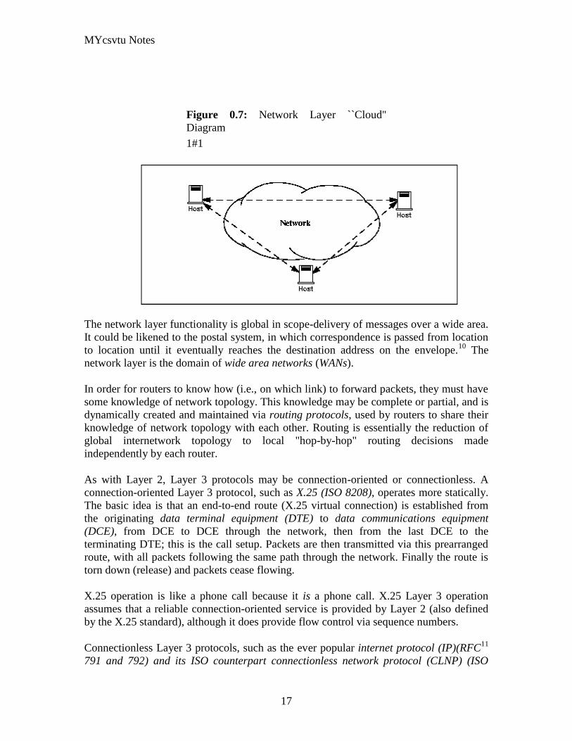
MYcsvtu Notes
17
Figure 07 Network Layer ``Cloud
Diagram
11
The network layer functionality is global in scope-delivery of messages over a wide area
It could be likened to the postal system in which correspondence is passed from location
to location until it eventually reaches the destination address on the envelope10
The
network layer is the domain of wide area networks (WANs)
In order for routers to know how (ie on which link) to forward packets they must have
some knowledge of network topology This knowledge may be complete or partial and is
dynamically created and maintained via routing protocols used by routers to share their
knowledge of network topology with each other Routing is essentially the reduction of
global internetwork topology to local hop-by-hop routing decisions made
independently by each router
As with Layer 2 Layer 3 protocols may be connection-oriented or connectionless A
connection-oriented Layer 3 protocol such as X25 (ISO 8208) operates more statically
The basic idea is that an end-to-end route (X25 virtual connection) is established from
the originating data terminal equipment (DTE) to data communications equipment
(DCE) from DCE to DCE through the network then from the last DCE to the
terminating DTE this is the call setup Packets are then transmitted via this prearranged
route with all packets following the same path through the network Finally the route is
torn down (release) and packets cease flowing
X25 operation is like a phone call because it is a phone call X25 Layer 3 operation
assumes that a reliable connection-oriented service is provided by Layer 2 (also defined
by the X25 standard) although it does provide flow control via sequence numbers
Connectionless Layer 3 protocols such as the ever popular internet protocol (IP)(RFC11
791 and 792) and its ISO counterpart connectionless network protocol (CLNP) (ISO
MYcsvtu Notes
18
8473) route packets dynamically There is no prearranged path which is followed by
subsequent packets flowing from one host to another Instead each packet is individually
routed through a routing mesh there is no reason to believe that sequential packets
flowing between hosts will follow the same path So sequence errors may be introduced
at Layer 3 which must be corrected by a higher layer entity
Connectionless data packets are commonly referred to as datagrams and the service
provided by connectionless Layer 3 protocols is referred to as datagram service Stateless
datagram service is simpler for Layer 3 entities than connection-oriented network layer
services Because there is no state information to maintain dynamic routing protocols can
be used If a router fails during the dialogue between two communicating hosts
neighboring routers will discover this via the routing protocols and find alternate routes
which bypass the failed router
There seems to be a fair amount of ambiguity between the network layer and the LLC
sublayer Both can provide connection-oriented or connectionless services to higher
layers To a large extent if Layer 3 is explicitly implemented there is no need for an
LLC sublayer The primary difference is in scope-LLC addresses and protocols are
oriented toward a more local environment whereas network layer addresses and protocols
are global in scope
Excellent references to routing and forwarding of data packets can be found in [PERL92]
and [STEN95]
Layer 4 - The Transport Layer
The transport layer is concerned with getting Layer 4 messages-called segments or more
formally transport protocol data units (TPDUs) -from source to destination in a reliable
manner The perspective of Layer 4 is of end-to-end communications rather than the hop-
by-hop perspective of Layer 3 Layer 4 assumes that packets can be moved from network
entity to network entity eventually getting to the final destination host How this is
accomplished is of no concern to Layer 4 functionality
Like other layers transport layer protocols can be either connection-oriented or
connectionless depending on the services required by higher layers A common
implementation of Layers 3 and 4 involves a connection-oriented transport layer protocol
running over a connectionless network layer protocol such as the ubiquitous TCPIP
protocol suite In this instance the communicating hosts maintain state information on
communications with each other to determine when and what to send This state
information defines the connection between the communicating Layer 4 entities
The general idea here is that two communicating hosts need not be concerned with the
topology of the internetwork which lies between them They only need to know the state
of their pairwise communication If part of the intervening internetwork cloud suffers a
failure the Layer 3 entities (routers) will deal with it and recover dynamically Aside
MYcsvtu Notes
19
from potential retransmission of any lost segments the hosts Layer 4 entries do not have
to be at all concerned with routing and recovery activities at Layer 3
In the IP protocol suite the primary connectionless Layer 4 protocol is the User
Datagram Protocol (UDP)(RFC 768) which is carried by IP the primary connection-
oriented protocol is the Transmission Control Protocol (TCP)(RFC 793) The ISO world
defines five classes of transport layer protocol beginning with Class 0 (TP-0) for
connectionless operation and range up to Class 4 (TP-4)(ISO 8073) for connection-
oriented operation
Layer 5 - The Session Layer
The session layer provides a control structure for communication between applications
on hosts The communication at layer 5 is called a session which defines the relative
timing of communications between the hosts applications Synchronization of
communicating applications comes into play when coordinated timing of corresponding
events at the endpoints is imperative such as in financial transactions
Remember layers define communication functions not implementations It is unlikely
that a session layer would be explicitly implemented as a stand-alone program although
its functions would be implemented somewhere Session layer functions depend on the
reliability of communications between the endpoints and session layer functions must
therefore be implemented above Layer 4
Layer 6 - The Presentation Layer
The presentation layer performs any necessary data transformations or formatting
required by the end applications Functions provided by the presentation layer include
data compression file formatting and encryption Common data formatting is important
because it allows the same application file to be accessed by the application running on
different computer platforms This book is itself the product of an application running on
different platforms with common files being modified via these different platforms
Abstract Syntax Notation (ASN1) is commonly used to specify data values in a way
which allows processors to communicate independent of their varying native integer
sizes bit orderings (big or little endian) character sets etc ASN1 is a transfer syntax a
presentation layer formatting which appears frequently in the CDPD specification for
unambiguous definition of network management accounting limited size messaging and
other functions
An example of ASN1 encoding from an accounting Traffic Matrix Segment in the
CDPD specification is the following
MYcsvtu Notes
20
TrafficType = INTEGER
registration (0)
deregistration (1)
ip(2)
clnp(3)
Layer 7 - The Application Layer
The application layer provides the services which directly support an application running
on a host These services are directly accessible by an application via common well-
known application program interfaces (APIs) which can actually occur at many layers
Examples of layer 7 services include FTP (file transfer protocol) Telnet and SNMP
(simple network management protocol) Most network management activities are based
on the services provided by layer 7 application entities which in turn rely on lower layer
services to be able to perform their functions
7 Application ECHO ENRP FTP Gopher HTTP NFS RTSP SIP SMTP SNMP
SSH Telnet Whois XMPP
6 Presentation XDR ASN1 SMB AFP NCP
5 Session ASAP TLS SSL ISO 8327 CCITT X225 RPC NetBIOS ASP
4 Transport TCP UDP RTP SCTP SPX ATP IL
3 Network IP ICMP IGMP IPX OSPF RIP IGRP EIGRP ARP RARP X25
2 Data Link Ethernet Token ring HDLC Frame relay ISDN ATM 80211 WiFi
FDDI PPP
1 Physical 10BASE-T 100BASE-T 1000BASE-T SONETSDH G709 T-
carrierE-carrier various 80211 physical layers
The TCPIP Reference Model
The TCPIP reference model is the network model used in the current Internet
architecture [19] It has its origins back in the 1960s with the grandfather of the Internet
the ARPANET This was a research network sponsored by the Department of Defense in
the United States The following were seen as major design goals
ability to connect multiple networks together seamlessly
ability for connections to remain intact as long as the source and destination
machines were functioning
MYcsvtu Notes
21
to be built on flexible architecture
The reference model was named after two of its main protocols TCP (Transmission
Control Protocol) [12] and IP (Internet Protocol)
They choose to build a packet-switched network based on a connectionless internetwork
layer
Figure 21 TCPIP Network Protocol
A detailed description of the reference model is beyond the scope of this document and
project The basic idea of the networking system is to allow one application on a host
computer to talk to another application on a different host computer
The application forms its request then passes the packet down to the lower layers which
add their own control information either a header or a footer onto the packet Finally the
packet reaches the physical layer and is transmitted through the cable onto the destination
host The packet then travels up through the different layers with each layer reading
deciphering and removing the header or footer that was attached by its counterpart on the
originating computer Finally the packet arrives at the application it was destined for
Even though technically each layer communicates with the layer above or below it the
process can be viewed as one layer talking to its partner on the host as figure 21 shows
The Host-to-Network Layer
The Host-to-Network layer interfaces the TCPIP protocol stack to the physical network
The TCPIP reference model does not specify in any great detail the operation of this
layer except that the host has to connect to the network using some protocol so it can
send IP packets over it
As it is not officially defined it varies from implementation to implementation with
vendors supplying their own version
MYcsvtu Notes
22
The Network Layer
The job of the network layer is to inject packets into any network and have them travel
independently to the destination The layer defines IP (Internet Protocol) for its official
packet format and protocol Packet routing is a major job of this protocol
The Transport Layer
The transport layer is the interface between the application layer and the complex
hardware of the network It is designed to allow peer entities on the source and
destination hosts to carry on conversations
Data may be user data or control data Two modes are available full-duplex and half
duplex In full-duplex operation both sides can transmit and receive data simultaneously
whereas in half duplex a side can only send or receive at one time
Interaction between the transport layer and the layers immediately above and below are
shown in figure 22 Any program running in the application layer has the ability to send
a message using TCP or UDP which are the two protocols defined for the transport layer
The application can communicate with the TCP or the UDP service whichever it
requires Both the TCP and UDP communicate with the Internet Protocol in the internet
layer In all cases communication is a two way process The applications can read and
write to the transport layer The diagram only shows two protocols in the transport layer
TTCP will also reside in this layer between the other two protocols and function in the
same manner
Figure 22 Interaction with Application Transport and Internet Layers
A message to be sent originates in the application layer This is then passed down onto
the appropriate protocol in the transport layer These protocols add a header to the
message for the corresponding transport layer in the destination machine for purposes of
reassembling the message The segment is then passed onto the internet layer where the
Internet Protocol adds a further header Finally the segment is passed onto the physical
MYcsvtu Notes
23
layer a header and a trailer are added at this stage Figure 23 shows the structure of the
final segment being sent
Figure 23 Transmitted Segment from TCPIP Network
The Application Layer
The original TCPIP specification described a number of different applications that fit
into the top layer of the protocol stack These applications include Telnet FTP SMTP
and DNS
Telnet is a program that supports the TELNET [13] protocol over TCP TELNET is a
general two-way communication protocol that can be used to connect to another host and
run applications on that host remotely
FTP (File Transfer Protocol) [14] is a protocol that was originally designed to promote
the sharing of files among computer users It shields the user from the variations of file
storage on different architectures and allows for a reliable and efficient transfer of data
SMTP (Simple Mail Transport Protocol) [15] is the protocol used to transport electronic
mail from one computer to another through a series of other computers along the route
DNS [10] (Domain Name System) resolves the numerical address of a network node into
its textual name or vice-versa It would translate wwwyahoocom to 2047117771 to
allow the routing protocols to find the host that the packet is destined for
What is a Topology
The physical topology of a network refers to the configuration of cables computers and
other peripherals Physical topology should not be confused with logical topology which
is the method used to pass information between workstations Logical topology was
discussed in the Protocol chapter
Main Types of Physical Topologies
The following sections discuss the physical topologies used in networks and other related
topics
Linear Bus
MYcsvtu Notes
24
Star
Star-Wired Ring
Tree
Considerations When Choosing a Topology
Summary Chart
Linear Bus
A linear bus topology consists of a main run of cable with a terminator at each end (See
fig 1) All nodes (file server workstations and peripherals) are connected to the linear
cable Ethernet and LocalTalk networks use a linear bus topology
Fig 1 Linear Bus topology
Advantages of a Linear Bus Topology
Easy to connect a computer or peripheral to a linear bus
Requires less cable length than a star topology
Disadvantages of a Linear Bus Topology
Entire network shuts down if there is a break in the main cable
Terminators are required at both ends of the backbone cable
Difficult to identify the problem if the entire network shuts down
Not meant to be used as a stand-alone solution in a large building
Star
A star topology is designed with each node (file server workstations and peripherals)
connected directly to a central network hub or concentrator (See fig 2)
Data on a star network passes through the hub or concentrator before continuing to its
destination The hub or concentrator manages and controls all functions of the network It
also acts as a repeater for the data flow This configuration is common with twisted pair
cable however it can also be used with coaxial cable or fiber optic cable
MYcsvtu Notes
25
Fig 2 Star topology
Advantages of a Star Topology
Easy to install and wire
No disruptions to the network then connecting or removing devices
Easy to detect faults and to remove parts
Disadvantages of a Star Topology
Requires more cable length than a linear topology
If the hub or concentrator fails nodes attached are disabled
More expensive than linear bus topologies because of the cost of the
concentrators
The protocols used with star configurations are usually Ethernet or LocalTalk Token
Ring uses a similar topology called the star-wired ring
Star-Wired Ring
A star-wired ring topology may appear (externally) to be the same as a star topology
Internally the MAU (multistation access unit) of a star-wired ring contains wiring that
allows information to pass from one device to another in a circle or ring (See fig 3) The
Token Ring protocol uses a star-wired ring topology
Tree
A tree topology combines characteristics of linear bus and star topologies It consists of
groups of star-configured workstations connected to a linear bus backbone cable (See fig
MYcsvtu Notes
26
4) Tree topologies allow for the expansion of an existing network and enable schools to
configure a network to meet their needs
Fig 4 Tree topology
Advantages of a Tree Topology
Point-to-point wiring for individual segments
Supported by several hardware and software venders
Disadvantages of a Tree Topology
Overall length of each segment is limited by the type of cabling used
If the backbone line breaks the entire segment goes down
More difficult to configure and wire than other topologies
5-4-3 Rule
A consideration in setting up a tree topology using Ethernet protocol is the 5-4-3 rule
One aspect of the Ethernet protocol requires that a signal sent out on the network cable
reach every part of the network within a specified length of time Each concentrator or
repeater that a signal goes through adds a small amount of time This leads to the rule that
between any two nodes on the network there can only be a maximum of 5 segments
connected through 4 repeatersconcentrators In addition only 3 of the segments may be
populated (trunk) segments if they are made of coaxial cable A populated segment is one
which has one or more nodes attached to it In Figure 4 the 5-4-3 rule is adhered to The
MYcsvtu Notes
27
furthest two nodes on the network have 4 segments and 3 repeatersconcentrators
between them
This rule does not apply to other network protocols or Ethernet networks where all fiber
optic cabling or a combination of a fiber backbone with UTP cabling is used If there is a
combination of fiber optic backbone and UTP cabling the rule is simply translated to 7-
6-5 rule
] Mesh
Full
Fully Connected The type of network topology in which each of the nodes of the network is
connected to each of the other nodes in the network with a point-to-point link ndash
this makes it possible for data to be simultaneously transmitted from any single
node to all of the other nodes
Note The physical fully connected mesh topology is generally too costly and
complex for practical networks although the topology is used when there are only
a small number of nodes to be interconnected[3]
Partial
Partially Connected The type of network topology in which some of the nodes of the network are
connected to more than one other node in the network with a point-to-point link ndash
this makes it possible to take advantage of some of the redundancy that is
provided by a physical fully connected mesh topology without the expense and
complexity required for a connection between every node in the network
Note In most practical networks that are based upon the physical partially
connected mesh topology all of the data that is transmitted between nodes in the
network takes the shortest path between nodes except in the case of a failure or
break in one of the links in which case the data takes an alternate path to the
destination ndash this implies that the nodes of the network possess some type of
logical routing algorithm to determine the correct path to use at any particular
time
[edit] Hybrid Network Topologies
The hybrid topology is a type of network topology that is composed of one or more
interconnections of two or more networks that are based upon different physical
topologies or a type of network topology that is composed of one or more
interconnections of two or more networks that are based upon the same physical
topology but where the physical topology of the network resulting from such an
interconnection does not meet the definition of the original physical topology of the
interconnected networks (eg the physical topology of a network that would result from
an interconnection of two or more networks that are based upon the physical star
topology might create a hybrid topology which resembles a mixture of the physical star
MYcsvtu Notes
28
and physical bus topologies or a mixture of the physical star and the physical tree
topologies depending upon how the individual networks are interconnected while the
physical topology of a network that would result from an interconnection of two or more
networks that are based upon the physical distributed bus network retains the topology of
a physical distributed bus network)
Star-Bus A type of network topology in which the central nodes of one or more individual
networks that are based upon the physical star topology are connected together
using a common bus network whose physical topology is based upon the
physical linear bus topology the endpoints of the common bus being terminated
with the characteristic impedance of the transmission medium where required ndash
eg two or more hubs connected to a common backbone with drop cables
through the port on the hub that is provided for that purpose (eg a properly
configured uplink port) would comprise the physical bus portion of the physical
star-bus topology while each of the individual hubs combined with the
individual nodes which are connected to them would comprise the physical star
portion of the physical star-bus topology
Star-of-Stars
Hierarchical Star A type of network topology that is composed of an interconnection of individual
networks that are based upon the physical star topology connected together in a
hierarchical fashion to form a more complex network ndash eg a top level central
node which is the hub of the top level physical star topology and to which other
second level central nodes are attached as the spoke nodes each of which in
turn may also become the central nodes of a third level physical star topology
Notes 1) The physical hierarchical star topology is not a combination of the physical
linear bus and the physical star topologies as cited in some texts as there is no
common linear bus within the topology although the top level hub which is the
beginning of the physical hierarchical star topology may be connected to the
backbone of another network such as a common carrier which is topologically
not considered to be a part of the local network ndash if the top level central node is
connected to a backbone that is considered to be a part of the local network then
the resulting network topology would be considered to be a hybrid topology that
is a mixture of the topology of the backbone network and the physical hierarchical
star topology
2) The physical hierarchical star topology is also sometimes incorrectly referred
to as a physical tree topology since its physical topology is hierarchical however
the physical hierarchical star topology does not have a structure that is determined
by a branching factor as is the case with the physical tree topology and therefore
nodes may be added to or removed from any node that is the hub of one of the
individual physical star topology networks within a network that is based upon the
physical hierarchical star topology
3) The physical hierarchical star topology is commonly used in outside plant
(OSP) cabling to connect various buildings to a central connection facility which
MYcsvtu Notes
29
may also house the demarcation point for the connection to the data transmission
facilities of a common carrier and in inside plant (ISP) cabling to connect
multiple wiring closets within a building to a common wiring closet within the
same building which is also generally where the main backbone or trunk that
connects to a larger network if any enters the building
Star-wired Ring A type of hybrid physical network topology that is a combination of the physical
star topology and the physical ring topology the physical star portion of the
topology consisting of a network in which each of the nodes of which the network
is composed are connected to a central node with a point-to-point link in a hub
and spoke fashion the central node being the hub and the nodes that are
attached to the central node being the spokes (eg a collection of point-to-point
links from the peripheral nodes that converge at a central node) in a fashion that is
identical to the physical star topology while the physical ring portion of the
topology consists of circuitry within the central node which routes the signals on
the network to each of the connected nodes sequentially in a circular fashion
Note In an 8025 Token Ring network the central node is called a Multistation
Access Unit (MAU)
Hybrid Mesh A type of hybrid physical network topology that is a combination of the physical
partially connected topology and one or more other physical topologies the mesh
portion of the topology consisting of redundant or alternate connections between
some of the nodes in the network ndash the physical hybrid mesh topology is
commonly used in networks which require a high degree of availability
Considerations When Choosing a Topology
Money A linear bus network may be the least expensive way to install a network
you do not have to purchase concentrators
Length of cable needed The linear bus network uses shorter lengths of cable
Future growth With a star topology expanding a network is easily done by
adding another concentrator
Cable type The most common cable in schools is unshielded twisted pair which
is most often used with star topologies
Summary Chart
Common Cable Common Protocol
Linear Bus Twisted Pair
Coaxial
Ethernet
LocalTalk
MYcsvtu Notes
30
Fiber
Star Twisted Pair
Fiber
Ethernet
LocalTalk
Star-Wired Ring Twisted Pair Token Ring
Tree
Twisted Pair
Coaxial
Fiber
Ethernet
Internet vs Web
The Internet and the World Wide Web are not synonymous the Internet is a collection of
interconnected computer networks linked by copper wires fiber-optic cables wireless
connections etc the Web is a collection of interconnected documents and other
resources linked by hyperlinks and URLs The World Wide Web is accessible via the
Internet as are many other services including e-mail file sharing and others described
below
The best way to define and distinguish between these terms is to understand the Internet
protocol suite This collection of protocols is organized into layers such that each layer
provides the foundation and the services required by the layer above In this conception
the term Internet refers to computer networks that all communicate with IP (Internet
protocol) and TCP (transfer control protocol) Once this networking structure is
established then other protocols can run ―on top These other protocols are sometimes
called services or applications Hypertext transfer protocol or HTTP is an application
layer protocol that links billions of files together into the World Wide Web
Common uses of the Internet
The World Wide Web
Through keyword-driven Internet research using search engines like Google
millions worldwide have easy instant access to a vast and diverse amount of
online information Compared to encyclopedias and traditional libraries the
World Wide Web has enabled a sudden and extreme decentralization of
information and data
Many individuals and some companies and groups have adopted the use of Web logs or
blogs which are largely used as easily-updatable online diaries Some commercial
organizations encourage staff to fill them with advice on their areas of specialization in
the hope that visitors will be impressed by the expert knowledge and free information
and be attracted to the corporation as a result One example of this practice is Microsoft
MYcsvtu Notes
31
whose product developers publish their personal blogs in order to pique the publics
interest in their work
For more information on the distinction between the World Wide Web and the Internet
itself mdash as in everyday use the two are sometimes confused mdash see Dark internet where
this is discussed in more detail
Remote access
The Internet allows computer users to connect to other computers and information stores
easily wherever they may be across the world They may do this with or without the use
of security authentication and encryption technologies depending on the requirements
This is encouraging new ways of working from home collaboration and information
sharing in many industries An accountant sitting at home can audit the books of a
company based in another country on a server situated in a third country that is remotely
maintained by IT specialists in a fourth These accounts could have been created by
home-working book-keepers in other remote locations based on information e-mailed to
them from offices all over the world Some of these things were possible before the
widespread use of the Internet but the cost of private leased lines would have made
many of them infeasible in practice
An office worker away from his desk perhaps the other side of the world on a business
trip or a holiday can open a remote desktop session into his normal office PC using a
secure Virtual Private Network (VPN) connection via the Internet This gives him
complete access to all his normal files and data including e-mail and other applications
while he is away
This concept is also referred to by some network security people as the Virtual Private
Nightmare because it extends the secure perimeter of a corporate network into its
employees homes this has been the source of some notable security breaches but also
provides security for the workers
Functions
File-sharing
Instant messaging
Internet fax
Search engine
World Wide Web
MYcsvtu Notes
32
Intranets
What are Intranets
bull Intranet is Intra+ Net so an Intranet is an internal or private Internet used strictly
within the confines of a company university or organization Inter means
between or among hence the difference between the Internet and an Intranet
Some formal definitions of Intranets
bull Brown amp Duguid ―Intranets help present and
circulate boundary objects
bull Choo Detlor amp Turnbull ―Intranetshellip support the creation sharing and use of
knowledge
bull Stenmark ―Intranets are organizationally
restricted
A technical definition
bull An Intranet is a network based on the internet TCPIP open standard An intranet
belongs to an organization and is designed to be accessible only by the
organizations members employees or others with authorization An intranets
Web site looks and act just like other Web sites but has a firewall surrounding it
to fend off unauthorized users
Design Of Intranets
Steps
bull Analyze the organizationlsquos information ecology
bull Identify the typical problems experienced by users
bull Analyze the information behaviors of these set of users
bull Create value added processes to resolve the problems of users and to improve the
Information Ecology
Value Added Processes
bull Intranets may be designed to improve the organizational information ecology
MYcsvtu Notes
33
bull Intranets provide a unified information space in which users can communicate
and collaborate with others
bull intranet applications and services may add value by supporting the organizationlsquos
knowledge creating and decision making process
Two Models of Online Environments
Centralized
Distributed
Centralized Environments
bull Before the web the centralized model was all we had (examples include
CompuServe Prodigy)
bull On the web centralized models include site-based services such as Yahoo
bull Most (all) college and university services are offered using the centralized
model
MYcsvtu Notes
34
bull But centralized environments are static inflexible expensive
Distributed Environments
bull The World Wide Web is an example of a distributed environment
bull Resources access are not centralized but scattered around the world
ndash Resources in the form of a network of connected (via DNS) web servers
ndash Access in the form of a network of connected (via DNS) internet service
providers
ndash Users in the form of individualized and connected (via HTTP) web
browsers
bull The big issue ndash integration ndash that is making different systems work together
Design Principles
Network Design Principles
ndash Specifies how networks differ from traditional learning
ndash The idea is that each principle confers an advantage over non-network
systems
ndash Can be used as a means of evaluating new technology
1 Decentralize
ndash Centralized networks have a characteristic starlsquo shape
bull Some entities have many connections
bull The vast majority have few
bull Eg broadcast network teacher in a classroom
ndash Decentralized networks form a mesh
bull The weight of connections flow is distributed
bull Balanced load = more stable
bull Foster connections between entities fill outlsquo the star
Distribute
ndash Network entities reside in different physical locations
bull Reduces risk of network failure
bull Reduces need for major infrastructure such as powerful servers
large bandwidth massive storage
ndash Examples
bull Peer-to-peer networks such as Kazaa Gnutella
bull Content syndication networks such as RSS
ndash Emphasis is on sharing not copying
bull Locallsquo copies are temporary
MYcsvtu Notes
35
Computer Graphics
Computer Graphics is about animation (films)
Games are very important in Computer Graphics
Medical Imaging is another driving force
Computer Aided Design too
Graphics Definitions
bull Point
ndash a location in space 2D or 3D
ndash sometimes denotes one pixel
bull Line
ndash straight path connecting two points
ndash infinitesimal width consistent density
ndash beginning and end on points
bull Vertex
ndash point in 3D
bull Edge
ndash line in 3D connecting two vertices
bull PolygonFaceFacet
ndash arbitrary shape formed by connected vertices
ndash fundamental unit of 3D computer graphics
bull Raster
ndash derived from TV systems for a row of pixels
ndash commonly referred to as a scanline
ndash does influence algorithms ndash reducing memory requirements parallelism
etc
ndash is the derivation of rasterization scan-line algorithms
Displays
bull Most desktop displays use a cathode ray tube (CRT) while portable computing
devices such as laptops incorporate liquid crystal display (LCD)
bull Because of their slimmer design and smaller energy consumption monitors using
LCD technologies are beginning to replace the venerable CRT on many desktops
Cathode-Ray Tubes
MYcsvtu Notes
36
bull Classical output device is a monitor
bull Cathode-Ray Tube (CRT)
ndash Invented by Karl Ferdinand Braun (1897)
ndash Beam of electrons directed from cathode (-)to phosphor-coated
(fluorescent) screen (anode (+))
ndash Directed by magnetic focusing and deflection coils (anodes) in vacuum
filled tube
ndash Phosphor emits photon of light when hit by an electron of varied
persistence (long 15-20 ms for texts short lt 1ms for animation)
ndash Refresh rate (50-60 Hz 72-76 Hz) to avoid flicker trail
ndash Phosphors are organic compounds characterized by their persistence and
their color (blue red green)
Cathode-Ray Tubes
bull Cathode-Ray Tube (CRT)
ndash Horizontal deflection and vertical deflection direct the electron beam to
any point on the screen
ndash Intensity knob regulates the flow of electrons by controlling the voltage at
the control grid (high voltage reduces the electron density and thus
brightness)
ndash Accelerating voltage from positive coating inside screen (anode screen) or
an accelerating anode
bull Image maintenance
ndash Charge distribution to store picture information
OR
ndash Refresh CRT refreshes the display constantly to maintain phosphor glow
Cathode-Ray Tubes
bullCathode-Ray Tube (CRT)
ndash Horizontal deflection and vertical deflection direct the electron beam to any point
on the screen
ndash Intensity knob regulates the flow of electrons by controlling the voltage at the
control grid (high voltage reduces the electron density and thus brightness)
ndash Accelerating voltage from positive coating inside screen (anode screen) or an
accelerating anode
bullImage maintenance
ndash Charge distribution to store picture information
OR
ndash Refresh CRT refreshes the display constantly to maintain phosphor glow
bull Characteristics of Cathode-Ray Tube (CRT)
MYcsvtu Notes
37
ndash Intensity is proportional to the number of electrons repelled in beam per
second (brightness)
ndash Resolution is the maximum number of points that can be displayed
without overlap is expressed as number of horizontal points by number of
vertical points points are called pixels (picture elements) example
resolution 1024 x 768 pixels Typical resolution is 1280 x 1024 pixels
bull High-definition systems high resolution systems
bull Focusing
ndash Focusing forces the electron beam to converge to a point on the monitor
screen
ndash Can be electrostatic (lens) or magnetic (field)
bull Deflection
ndash Deflection directs the electron beam horizontally andor vertically to any
point on the screen
ndash Can be controlled by electric (deflection plates slide 9) or magnetic fields
(deflection coils slide 5)
ndash Magnetic coils two pairs (topbottom leftright) of tube neck
ndash Electric plates two pairs (horizontal vertical)
Raster-scan Displays
bullVideo displays can be either raster-scan or random-scan displays
bullRaster-scan display is the most common type of monitor using a CRT
bullThe electron beam scans the screen from top to bottom one row at a time Each row is
called a scan line
bullThe electron beam is turned on and off to produce a collection of dots painted one row at
a time These will form the image
bullA raster is a matrix of pixels covering the screen area and is composed of raster lines
Raster-scan Displays
MYcsvtu Notes
38
Raster-scan Displays
bullThe image is stored in a frame buffer containing the total screen area and where each
memory location corresponds to a pixel
bullIn a monochrome system each bit is 1 or 0 for the corresponding pixel to be on or off
(bitmap)
bullThe display processor scans the frame buffer to turn electron beam onoff depending if
the bit is 1 or 0
bullFor color monitors the frame buffer also contains the color of each pixel (color buffer)
as well as other characteristics of the image (gray scale hellip) 8 bitspixel 0255
(pixmap)
bullDepth of the buffer area is the number of bits per pixel (bit planes) up to 24
bullExamples television panels printers PC monitors (99 of raster-scan)
Raster-scan Displays
bullRefresh rate 24 is a minimum to avoid flicker corresponding to 24 Hz (1 Hz = 1 refresh
per second)
bullCurrent raster-scan displays have a refresh rate of at least 60 frames (60 Hz) per second
up to 120 (120 Hz)
bullUses large memory 640x480 307200 bits 38 kB
bullRefresh procedure
MYcsvtu Notes
39
ndashHorizontal retrace ndash beam returns to left of screen
ndashVertical retrace ndash bean returns to top left corner of screen
ndashInterlaced refresh ndash display first even-numbered lines then odd-numbered lines
permits to see the image in half the time
useful for slow refresh rates (30 Hz shows as 60 Hz)
Random-scan Displays
bullRandom scan systems are also called vector stroke-writing or calligraphic displays
bullThe electron beam directly draws the picture in any specified order
bullA pen plotter is an example of such a system
bullPicture is stored in a display list refresh display file vector file or display program as a
set of line drawing commands
bullRefreshes by scanning the list 30 to 60 times per second
bullMore suited for line-drawing applications such as architecture and manufacturing
Random-scan Displays
bullAdvantages
ndashHigh resolution
ndashEasy animation
ndashRequires little memory
bullDisadvantages
ndashRequires intelligent electron beam (processor controlled)
ndashLimited screen density limited to simple line-based images
ndashLimited color capability
bullImproved in the 1960lsquos by the Direct View Storage Tube (DVST) from Tektronix
Color CRT Monitor
Uses different phosphors a combination of Red Green and Blue to produce any color
Two methods
Random scan uses beam penetration
2 layers (Red Green) phosphors low speed electrons excite Red high speed electrons
excite Green interrmediate speed excite both to get yellow and orange Color is
controlled by electron beam voltage
Only produces a restricted set of colors
Raster scan uses a shadow mask with three electron guns Red Green and Blue (RGB
color model) Color is produced by adjusting the intensity level of each electron beam
Produces a wide range of colors from 8 to several millions
Raster scan
Most common as found in televisions
Beam scanned left to right flicked back to rescan from top to bottom then repeated
Repeated at 30Hz per frame sometimes higher to reduce flicker Interlacing scanning
MYcsvtu Notes
40
odd lines in whole screen then even lines is also used to reduce flicker Can also use
high-persistence phosphor to reduce flicker but causes image smearing especially with
significant animation
Resolution typically 512x512 but high-quality screens are available (and becoming more
common) at up to approximately 1600x1200 pixels Sun workstations have screens of
1192x980 pixels
Black amp white screens can display grayscale by varying the intensity of the electron
beam
Colour is achieved using three electron guns which hit red green or blue phosphors
Combining these colours can produce many others including white (all on) Phosphor
dots focused using a shadow mask - makes colour screens lower resolution than
monochrome
Alternative approach beam penetration Special phosphor glows a different colour
depending on intensity of beam
Colour or intensity at pixel held by computerlsquos video card 1 bitpixel can store offon
information hence only black ampwhite More bitspixel give rise to more colour
possibilities eg 8 bitspixel gives rise to 2^8=256 possible colours at any one time
Random Scan (Directed-beam refresh vector display)
Instead of scanning the whole display sequentially and horizontally the random scan
draws the lines to be displayed directly Screen update at gt30Hz to reduce flicker
Jaggies not found and higher resolutions possible (up to 4096x4096 pixels) Colour
achieved using beam penetration generally of poorer quality Eye strain and fatigue still
a problem and vector displays are more expensive
Direct view storage tube (DVST)
Used a lot in analogue storage oscilloscopes
Similar to random scan crt but image maintained by flood guns - no flicker Can be
incrementally updated but not selectively erased image has to be redrawn on completely
erased screen High resolution (typically 4096x3120 pixels) but low contrast low
brightness and difficulty in displaying colour
What is a Multimedia System
bull A system that involves
ndash generation
ndash representation
ndash storage
ndash transmission
ndash search and retrieval
ndash delivery
MYcsvtu Notes
41
of multimedia information
productionauthoring tools
compression and formats
file system design
networking issues
database management
server design streaming
Multimedia System Architecture
Information management subsystem Presentation Query
Storage subsystem Efficiently stored
amp retrieved
Network subsystem Delivery
Adaptation in Multimedia Systems
bull Multimedia systems can profit a lot from personalization
ndash User behavior
ndash User properties
bull Adaptation
ndash Models
ndash Mechanisms
Multimedia in a mobile environment
MYcsvtu Notes
42
bull Applications
ndash Emergency response systems mobile commerce phone service
entertainment games
What is Sound
A ripple is a pressure wave in water created by an object striking the water
Sound is a pressure wave in air created for example by an object such as a string
or our vocal cords vibrating Dark here represents more pressure light represents
less
MYcsvtu Notes
43
Sine Waves Form Pure Tones
This simple sound wave is a Sine Wave a Pure tone produced by a simple vibration
Sine Wave Sample Tone
This can be represented graphically as shown above
Converting Pressure into Voltage
The pressure wave of sound moves a diaphragm in the microphone which produces a
voltage proportional to the pressure of the sound wave at each instant
Animation
MYcsvtu Notes
44
bull Animation is the rapid display of a sequence of images of 2-D artwork or model
positions in order to create an illusion of movement It is an optical illusion of
motion due to the phenomenon of persistence of vision This could be anything
from a flip book to a motion picture film Animation deals with the generation
sequencing and display a set of images which is called frames to create an effect
of visual change or motion similar to a movie film
bull Animation is used in those instance where videography is not possible
Hardware Requirement For Animation
bull Image Generation Tools amp Devices
bull Computer monitors with image display Capability
Software Requirement For Animation
bull Animation creating software
bull Screen Capture Software
bull Animation Clips
bull Software support For High Resolution
bull Recording amp Playback Capability
bull Transition effect
Early animation
There is no single person that can be considered the creator of the art of animation as
there were several people doing several projects which could be considered various types
of animation all around the same time (Short hand-drawn animation scenes could be
presented with the Phenakistoscope the Zoetrope and other optical toys already in the
early 1800s)
The following is a brief listing on those who are often acknowledged as significant to the
development of animation Note that this list is by no means a comprehensive list of
contributors to early animation
Georges Meacuteliegraves was a creator of special effect films such as A Trip to the Moon He
used many techniques ndash one of which was to stop the camera rolling change something
in the scene and then continue rolling the film This is a very similar idea to that of stop-
motion animation Meacuteliegraves accidentally happened upon the technique when his camera
broke down while shooting a bus driving by When the camera was fixed a horse
happened to be passing by just as Meacuteliegraves continued to film The result was that the bus
appeared to change into a horse
MYcsvtu Notes
45
Fantasmagorie by Emile Cohl 1908
Eacutemile Cohl began drawing cartoon strips and created a film in 1908 called
Fantasmagorie The film largely consisted of a stick figure moving about and
encountering all manner of morphing objects such as a wine bottle that transforms into a
flower There were also sections of live action where the animatorlsquos hands would enter
the scene The film was created by drawing each frame on paper and then shooting each
frame onto negative film which gave the picture a blackboard look
Winsor McCay created detailed animations that required a team of artists and painstaking
attention for detail Each frame was drawn on paper requiring backgrounds to be
redrawn as well characters to be animated His films such as Gertie the Dinosaur (1914)
and The Sinking of the Lusitania (1918) were of an impressive scale although The
Sinking of the Lusitania used cels
In 1919 Otto Messmer created the character of Felix the cat for Pat Sullivans animation
studios The importance of Felix lies in the characters strong personality created largely
through gesture and actions
Animation techniques
Animation techniques are incredibly varied and difficult to categorize Techniques are
often related or combined The following is a brief on common types of animation
Again this list is by no means comprehensive
Traditional animation
An example of traditional animation a horse animated by rotoscoping from Edweard
Muybridges 19th century photos
Main article Traditional animation
MYcsvtu Notes
46
Also called cel animation the frames of a traditionally animated movie are hand-drawn
The drawings are traced or copied onto transparent acetate sheets called cels which are
then placed over a painted background and photographed one by one on a rostrum
camera Nowadays the use of cels (and cameras) is mostly obsolete since the drawings
are scanned into computers and digitally transferred directly to 35 mm film The look
of traditional cel animation is still preserved and the character animators work has
remained essentially the same over the past 70 years Because of the digital influence
over modern cel animation it is also known as tradigital animation
Examples The Lion King Spirited Away Les Triplettes de Belleville
Full animation The most common style in animation known for its realistic and often very detailed art
Examples All Disney feature length animated films The Secret of NIMH The Iron Giant
Limited animation A cheaper process of making animated cartoons that does not follow a realistic
approach
Examples The Flintstones Yellow Submarine
Rubber hose The characters are usually cartoony and the animators have a lot of artistic freedom as
rubber hose animations dont have to follow the laws of physics and anatomy in the same
degree as the other main styles in animation
Examples Early Mickey Mouse cartoons Ren and Stimpy Popeye
Rotoscoping A technique where animators trace live action movement frame by frame for use in
animated films
Examples Gullivers Travels American Pop
Stop motion
Stop-motion animation is any type of animation which requires the animator to physically
alter the scene shoot a frame again alter the scene and shoot a frame and so on to create
the animation There are many different types of stop-motion animation some noteable
examples are listed below
Clay animation
MYcsvtu Notes
47
A clay animation scene from a TV commercial
Often abbreviated to claymation this is a type of stop-motion animation using
figures made of clay or a similar malleable material The figures may have an
armature or wire frame inside of them similar to puppet animation (below)
Alternatively the figures may be made entirely of clay such as in the films of
Bruce Bickford where clay creatures morph into a variety of different shapes
Examples Wallace and Gromit Dimensions of Dialogue by Jan Švankmajer The
Amazing Mr Bickford The Trap Door
Cutout animation In this type of stop-motion animation the animation is formed by moving 2-
dimensional pieces of material such as paper or cloth
Examples the animated sequences of Monty Pythons Flying Circus (often
referred to as Dada animation named after the Dada art movement[citation needed]
)
Tale of Tales early episodes of South Park
Silhouette animation A type of cutout animation where the viewer only sees black silhouettes
Example The Adventures of Prince Achmed the worlds oldest surviving
animated feature film from 1926
Graphic animation
Model animation In this form of animation model animated characters interact with and are a part
of the live-action world
Examples The films of Ray Harryhausen (Jason and the Argonauts) and Willis
OBrien (King Kong)
Go motion
Object animation
Pixilation Examples Neighbours
Puppet animation Puppet animation typically involves puppet figures interacting with each other in
a constructed environment in contrast to the real-world interaction in model
MYcsvtu Notes
48
animation (above) The puppets generally have an armature inside of them to
keep them still and steady as well as constraining them to move at particular
joints
Examples The Nightmare Before Christmas Robot Chicken The Tale of the Fox
Brickfilm
Puppetoon
Computer animation
A short gif animation
Like stop motion computer animation encompasses a variety of techniques the unifying
idea being that the animation is created digitally on a computer
2D animation Figures are created andor edited on the computer using 2D bitmap graphics or
created and edited using 2D vector graphics This includes automated
computerized versions of traditional animation techniques such as of tweening
morphing onion skinning and interpolated rotoscoping
Examples A Scanner Darkly Jib Jab
Analog computer animation
Flash animation
PowerPoint animation
A completely synthetic computer-generated scene
3D animation
MYcsvtu Notes
49
Figures are created in the computer using polygons To allow these meshes to
move they are given a digital armature (sculpture) This process is called rigging
Various other techniques can be applied such as mathematical functions
(gravity) simulated fur or hair effects such as fire and water and the use of
motion capture to name but a few
Examples The Incredibles Shrek
Cel-shaded animation
Morph target animation
Skeletal animation
Motion capture
Crowd simulation
Less common techniques
Drawn on film animation A technique where footage is produced by creating the
images directly on film stock
Paint-on-glass animationA technique for making animated films by manipulating slow-
drying oil paints on sheets of glass
Pinscreen animation Makes use of a screen filled with movable pins which can be
moved in or out by pressing an object onto the screen The screen is lit from the side so
that the pins cast shadows The technique has been used to create animated films with a
range of textural effects difficult to achieve with traditional cel animation
Sand animation Sand is moved around on a backlighted or frontlighted piece of glass to
create each frame for an animated film
Multimedia
Multimedia (Lat Multum + Medium) is media that uses multiple forms of information
content and information processing (eg text audio graphics animation video
interactivity) to inform or entertain the (user) audience Multimedia also refers to the use
of (but not limited to) electronic media to store and experience multimedia content
Multimedia is similar to traditional mixed media in fine art but with a broader scope The
term rich media is synonymous for interactive multimedia
Categorization
Multimedia may be broadly divided into linear and non-linear categories Linear active
content progresses without any navigation control for the viewer such as a cinema
presentation Non-linear content offers user interactivity to control progress as used with
MYcsvtu Notes
50
a computer game or used in self-paced computer based training Non-linear content is
also known as hypermedia content
Multimedia presentations can be live or recorded A recorded presentation may allow
interactivity via a navigation system A live multimedia presentation may allow
interactivity via interaction with the presenter or performer
There are 2 basic way to represent some information
Unimedium Presentation
Multimedia Presentation
In case of computer system the commonly used medioa for the purpose of storage
access and transmission of information are
bull Text
bull Graphics
bull Animation
bull Audio
bull Video
Multimedia Computer System require
bull Faster CPU
bull Larger Storage Devices
bull Larger Main Memory
bull Good Graphics Terminal
bull IO devices required to play an audio associated with the program
Transmission Mode
bull Asynchronous
bull Synchronous
bull Isochronous
MYcsvtu Notes
20
TrafficType = INTEGER
registration (0)
deregistration (1)
ip(2)
clnp(3)
Layer 7 - The Application Layer
The application layer provides the services which directly support an application running
on a host These services are directly accessible by an application via common well-
known application program interfaces (APIs) which can actually occur at many layers
Examples of layer 7 services include FTP (file transfer protocol) Telnet and SNMP
(simple network management protocol) Most network management activities are based
on the services provided by layer 7 application entities which in turn rely on lower layer
services to be able to perform their functions
7 Application ECHO ENRP FTP Gopher HTTP NFS RTSP SIP SMTP SNMP
SSH Telnet Whois XMPP
6 Presentation XDR ASN1 SMB AFP NCP
5 Session ASAP TLS SSL ISO 8327 CCITT X225 RPC NetBIOS ASP
4 Transport TCP UDP RTP SCTP SPX ATP IL
3 Network IP ICMP IGMP IPX OSPF RIP IGRP EIGRP ARP RARP X25
2 Data Link Ethernet Token ring HDLC Frame relay ISDN ATM 80211 WiFi
FDDI PPP
1 Physical 10BASE-T 100BASE-T 1000BASE-T SONETSDH G709 T-
carrierE-carrier various 80211 physical layers
The TCPIP Reference Model
The TCPIP reference model is the network model used in the current Internet
architecture [19] It has its origins back in the 1960s with the grandfather of the Internet
the ARPANET This was a research network sponsored by the Department of Defense in
the United States The following were seen as major design goals
ability to connect multiple networks together seamlessly
ability for connections to remain intact as long as the source and destination
machines were functioning
MYcsvtu Notes
21
to be built on flexible architecture
The reference model was named after two of its main protocols TCP (Transmission
Control Protocol) [12] and IP (Internet Protocol)
They choose to build a packet-switched network based on a connectionless internetwork
layer
Figure 21 TCPIP Network Protocol
A detailed description of the reference model is beyond the scope of this document and
project The basic idea of the networking system is to allow one application on a host
computer to talk to another application on a different host computer
The application forms its request then passes the packet down to the lower layers which
add their own control information either a header or a footer onto the packet Finally the
packet reaches the physical layer and is transmitted through the cable onto the destination
host The packet then travels up through the different layers with each layer reading
deciphering and removing the header or footer that was attached by its counterpart on the
originating computer Finally the packet arrives at the application it was destined for
Even though technically each layer communicates with the layer above or below it the
process can be viewed as one layer talking to its partner on the host as figure 21 shows
The Host-to-Network Layer
The Host-to-Network layer interfaces the TCPIP protocol stack to the physical network
The TCPIP reference model does not specify in any great detail the operation of this
layer except that the host has to connect to the network using some protocol so it can
send IP packets over it
As it is not officially defined it varies from implementation to implementation with
vendors supplying their own version
MYcsvtu Notes
22
The Network Layer
The job of the network layer is to inject packets into any network and have them travel
independently to the destination The layer defines IP (Internet Protocol) for its official
packet format and protocol Packet routing is a major job of this protocol
The Transport Layer
The transport layer is the interface between the application layer and the complex
hardware of the network It is designed to allow peer entities on the source and
destination hosts to carry on conversations
Data may be user data or control data Two modes are available full-duplex and half
duplex In full-duplex operation both sides can transmit and receive data simultaneously
whereas in half duplex a side can only send or receive at one time
Interaction between the transport layer and the layers immediately above and below are
shown in figure 22 Any program running in the application layer has the ability to send
a message using TCP or UDP which are the two protocols defined for the transport layer
The application can communicate with the TCP or the UDP service whichever it
requires Both the TCP and UDP communicate with the Internet Protocol in the internet
layer In all cases communication is a two way process The applications can read and
write to the transport layer The diagram only shows two protocols in the transport layer
TTCP will also reside in this layer between the other two protocols and function in the
same manner
Figure 22 Interaction with Application Transport and Internet Layers
A message to be sent originates in the application layer This is then passed down onto
the appropriate protocol in the transport layer These protocols add a header to the
message for the corresponding transport layer in the destination machine for purposes of
reassembling the message The segment is then passed onto the internet layer where the
Internet Protocol adds a further header Finally the segment is passed onto the physical
MYcsvtu Notes
23
layer a header and a trailer are added at this stage Figure 23 shows the structure of the
final segment being sent
Figure 23 Transmitted Segment from TCPIP Network
The Application Layer
The original TCPIP specification described a number of different applications that fit
into the top layer of the protocol stack These applications include Telnet FTP SMTP
and DNS
Telnet is a program that supports the TELNET [13] protocol over TCP TELNET is a
general two-way communication protocol that can be used to connect to another host and
run applications on that host remotely
FTP (File Transfer Protocol) [14] is a protocol that was originally designed to promote
the sharing of files among computer users It shields the user from the variations of file
storage on different architectures and allows for a reliable and efficient transfer of data
SMTP (Simple Mail Transport Protocol) [15] is the protocol used to transport electronic
mail from one computer to another through a series of other computers along the route
DNS [10] (Domain Name System) resolves the numerical address of a network node into
its textual name or vice-versa It would translate wwwyahoocom to 2047117771 to
allow the routing protocols to find the host that the packet is destined for
What is a Topology
The physical topology of a network refers to the configuration of cables computers and
other peripherals Physical topology should not be confused with logical topology which
is the method used to pass information between workstations Logical topology was
discussed in the Protocol chapter
Main Types of Physical Topologies
The following sections discuss the physical topologies used in networks and other related
topics
Linear Bus
MYcsvtu Notes
24
Star
Star-Wired Ring
Tree
Considerations When Choosing a Topology
Summary Chart
Linear Bus
A linear bus topology consists of a main run of cable with a terminator at each end (See
fig 1) All nodes (file server workstations and peripherals) are connected to the linear
cable Ethernet and LocalTalk networks use a linear bus topology
Fig 1 Linear Bus topology
Advantages of a Linear Bus Topology
Easy to connect a computer or peripheral to a linear bus
Requires less cable length than a star topology
Disadvantages of a Linear Bus Topology
Entire network shuts down if there is a break in the main cable
Terminators are required at both ends of the backbone cable
Difficult to identify the problem if the entire network shuts down
Not meant to be used as a stand-alone solution in a large building
Star
A star topology is designed with each node (file server workstations and peripherals)
connected directly to a central network hub or concentrator (See fig 2)
Data on a star network passes through the hub or concentrator before continuing to its
destination The hub or concentrator manages and controls all functions of the network It
also acts as a repeater for the data flow This configuration is common with twisted pair
cable however it can also be used with coaxial cable or fiber optic cable
MYcsvtu Notes
25
Fig 2 Star topology
Advantages of a Star Topology
Easy to install and wire
No disruptions to the network then connecting or removing devices
Easy to detect faults and to remove parts
Disadvantages of a Star Topology
Requires more cable length than a linear topology
If the hub or concentrator fails nodes attached are disabled
More expensive than linear bus topologies because of the cost of the
concentrators
The protocols used with star configurations are usually Ethernet or LocalTalk Token
Ring uses a similar topology called the star-wired ring
Star-Wired Ring
A star-wired ring topology may appear (externally) to be the same as a star topology
Internally the MAU (multistation access unit) of a star-wired ring contains wiring that
allows information to pass from one device to another in a circle or ring (See fig 3) The
Token Ring protocol uses a star-wired ring topology
Tree
A tree topology combines characteristics of linear bus and star topologies It consists of
groups of star-configured workstations connected to a linear bus backbone cable (See fig
MYcsvtu Notes
26
4) Tree topologies allow for the expansion of an existing network and enable schools to
configure a network to meet their needs
Fig 4 Tree topology
Advantages of a Tree Topology
Point-to-point wiring for individual segments
Supported by several hardware and software venders
Disadvantages of a Tree Topology
Overall length of each segment is limited by the type of cabling used
If the backbone line breaks the entire segment goes down
More difficult to configure and wire than other topologies
5-4-3 Rule
A consideration in setting up a tree topology using Ethernet protocol is the 5-4-3 rule
One aspect of the Ethernet protocol requires that a signal sent out on the network cable
reach every part of the network within a specified length of time Each concentrator or
repeater that a signal goes through adds a small amount of time This leads to the rule that
between any two nodes on the network there can only be a maximum of 5 segments
connected through 4 repeatersconcentrators In addition only 3 of the segments may be
populated (trunk) segments if they are made of coaxial cable A populated segment is one
which has one or more nodes attached to it In Figure 4 the 5-4-3 rule is adhered to The
MYcsvtu Notes
27
furthest two nodes on the network have 4 segments and 3 repeatersconcentrators
between them
This rule does not apply to other network protocols or Ethernet networks where all fiber
optic cabling or a combination of a fiber backbone with UTP cabling is used If there is a
combination of fiber optic backbone and UTP cabling the rule is simply translated to 7-
6-5 rule
] Mesh
Full
Fully Connected The type of network topology in which each of the nodes of the network is
connected to each of the other nodes in the network with a point-to-point link ndash
this makes it possible for data to be simultaneously transmitted from any single
node to all of the other nodes
Note The physical fully connected mesh topology is generally too costly and
complex for practical networks although the topology is used when there are only
a small number of nodes to be interconnected[3]
Partial
Partially Connected The type of network topology in which some of the nodes of the network are
connected to more than one other node in the network with a point-to-point link ndash
this makes it possible to take advantage of some of the redundancy that is
provided by a physical fully connected mesh topology without the expense and
complexity required for a connection between every node in the network
Note In most practical networks that are based upon the physical partially
connected mesh topology all of the data that is transmitted between nodes in the
network takes the shortest path between nodes except in the case of a failure or
break in one of the links in which case the data takes an alternate path to the
destination ndash this implies that the nodes of the network possess some type of
logical routing algorithm to determine the correct path to use at any particular
time
[edit] Hybrid Network Topologies
The hybrid topology is a type of network topology that is composed of one or more
interconnections of two or more networks that are based upon different physical
topologies or a type of network topology that is composed of one or more
interconnections of two or more networks that are based upon the same physical
topology but where the physical topology of the network resulting from such an
interconnection does not meet the definition of the original physical topology of the
interconnected networks (eg the physical topology of a network that would result from
an interconnection of two or more networks that are based upon the physical star
topology might create a hybrid topology which resembles a mixture of the physical star
MYcsvtu Notes
28
and physical bus topologies or a mixture of the physical star and the physical tree
topologies depending upon how the individual networks are interconnected while the
physical topology of a network that would result from an interconnection of two or more
networks that are based upon the physical distributed bus network retains the topology of
a physical distributed bus network)
Star-Bus A type of network topology in which the central nodes of one or more individual
networks that are based upon the physical star topology are connected together
using a common bus network whose physical topology is based upon the
physical linear bus topology the endpoints of the common bus being terminated
with the characteristic impedance of the transmission medium where required ndash
eg two or more hubs connected to a common backbone with drop cables
through the port on the hub that is provided for that purpose (eg a properly
configured uplink port) would comprise the physical bus portion of the physical
star-bus topology while each of the individual hubs combined with the
individual nodes which are connected to them would comprise the physical star
portion of the physical star-bus topology
Star-of-Stars
Hierarchical Star A type of network topology that is composed of an interconnection of individual
networks that are based upon the physical star topology connected together in a
hierarchical fashion to form a more complex network ndash eg a top level central
node which is the hub of the top level physical star topology and to which other
second level central nodes are attached as the spoke nodes each of which in
turn may also become the central nodes of a third level physical star topology
Notes 1) The physical hierarchical star topology is not a combination of the physical
linear bus and the physical star topologies as cited in some texts as there is no
common linear bus within the topology although the top level hub which is the
beginning of the physical hierarchical star topology may be connected to the
backbone of another network such as a common carrier which is topologically
not considered to be a part of the local network ndash if the top level central node is
connected to a backbone that is considered to be a part of the local network then
the resulting network topology would be considered to be a hybrid topology that
is a mixture of the topology of the backbone network and the physical hierarchical
star topology
2) The physical hierarchical star topology is also sometimes incorrectly referred
to as a physical tree topology since its physical topology is hierarchical however
the physical hierarchical star topology does not have a structure that is determined
by a branching factor as is the case with the physical tree topology and therefore
nodes may be added to or removed from any node that is the hub of one of the
individual physical star topology networks within a network that is based upon the
physical hierarchical star topology
3) The physical hierarchical star topology is commonly used in outside plant
(OSP) cabling to connect various buildings to a central connection facility which
MYcsvtu Notes
29
may also house the demarcation point for the connection to the data transmission
facilities of a common carrier and in inside plant (ISP) cabling to connect
multiple wiring closets within a building to a common wiring closet within the
same building which is also generally where the main backbone or trunk that
connects to a larger network if any enters the building
Star-wired Ring A type of hybrid physical network topology that is a combination of the physical
star topology and the physical ring topology the physical star portion of the
topology consisting of a network in which each of the nodes of which the network
is composed are connected to a central node with a point-to-point link in a hub
and spoke fashion the central node being the hub and the nodes that are
attached to the central node being the spokes (eg a collection of point-to-point
links from the peripheral nodes that converge at a central node) in a fashion that is
identical to the physical star topology while the physical ring portion of the
topology consists of circuitry within the central node which routes the signals on
the network to each of the connected nodes sequentially in a circular fashion
Note In an 8025 Token Ring network the central node is called a Multistation
Access Unit (MAU)
Hybrid Mesh A type of hybrid physical network topology that is a combination of the physical
partially connected topology and one or more other physical topologies the mesh
portion of the topology consisting of redundant or alternate connections between
some of the nodes in the network ndash the physical hybrid mesh topology is
commonly used in networks which require a high degree of availability
Considerations When Choosing a Topology
Money A linear bus network may be the least expensive way to install a network
you do not have to purchase concentrators
Length of cable needed The linear bus network uses shorter lengths of cable
Future growth With a star topology expanding a network is easily done by
adding another concentrator
Cable type The most common cable in schools is unshielded twisted pair which
is most often used with star topologies
Summary Chart
Common Cable Common Protocol
Linear Bus Twisted Pair
Coaxial
Ethernet
LocalTalk
MYcsvtu Notes
30
Fiber
Star Twisted Pair
Fiber
Ethernet
LocalTalk
Star-Wired Ring Twisted Pair Token Ring
Tree
Twisted Pair
Coaxial
Fiber
Ethernet
Internet vs Web
The Internet and the World Wide Web are not synonymous the Internet is a collection of
interconnected computer networks linked by copper wires fiber-optic cables wireless
connections etc the Web is a collection of interconnected documents and other
resources linked by hyperlinks and URLs The World Wide Web is accessible via the
Internet as are many other services including e-mail file sharing and others described
below
The best way to define and distinguish between these terms is to understand the Internet
protocol suite This collection of protocols is organized into layers such that each layer
provides the foundation and the services required by the layer above In this conception
the term Internet refers to computer networks that all communicate with IP (Internet
protocol) and TCP (transfer control protocol) Once this networking structure is
established then other protocols can run ―on top These other protocols are sometimes
called services or applications Hypertext transfer protocol or HTTP is an application
layer protocol that links billions of files together into the World Wide Web
Common uses of the Internet
The World Wide Web
Through keyword-driven Internet research using search engines like Google
millions worldwide have easy instant access to a vast and diverse amount of
online information Compared to encyclopedias and traditional libraries the
World Wide Web has enabled a sudden and extreme decentralization of
information and data
Many individuals and some companies and groups have adopted the use of Web logs or
blogs which are largely used as easily-updatable online diaries Some commercial
organizations encourage staff to fill them with advice on their areas of specialization in
the hope that visitors will be impressed by the expert knowledge and free information
and be attracted to the corporation as a result One example of this practice is Microsoft
MYcsvtu Notes
31
whose product developers publish their personal blogs in order to pique the publics
interest in their work
For more information on the distinction between the World Wide Web and the Internet
itself mdash as in everyday use the two are sometimes confused mdash see Dark internet where
this is discussed in more detail
Remote access
The Internet allows computer users to connect to other computers and information stores
easily wherever they may be across the world They may do this with or without the use
of security authentication and encryption technologies depending on the requirements
This is encouraging new ways of working from home collaboration and information
sharing in many industries An accountant sitting at home can audit the books of a
company based in another country on a server situated in a third country that is remotely
maintained by IT specialists in a fourth These accounts could have been created by
home-working book-keepers in other remote locations based on information e-mailed to
them from offices all over the world Some of these things were possible before the
widespread use of the Internet but the cost of private leased lines would have made
many of them infeasible in practice
An office worker away from his desk perhaps the other side of the world on a business
trip or a holiday can open a remote desktop session into his normal office PC using a
secure Virtual Private Network (VPN) connection via the Internet This gives him
complete access to all his normal files and data including e-mail and other applications
while he is away
This concept is also referred to by some network security people as the Virtual Private
Nightmare because it extends the secure perimeter of a corporate network into its
employees homes this has been the source of some notable security breaches but also
provides security for the workers
Functions
File-sharing
Instant messaging
Internet fax
Search engine
World Wide Web
MYcsvtu Notes
32
Intranets
What are Intranets
bull Intranet is Intra+ Net so an Intranet is an internal or private Internet used strictly
within the confines of a company university or organization Inter means
between or among hence the difference between the Internet and an Intranet
Some formal definitions of Intranets
bull Brown amp Duguid ―Intranets help present and
circulate boundary objects
bull Choo Detlor amp Turnbull ―Intranetshellip support the creation sharing and use of
knowledge
bull Stenmark ―Intranets are organizationally
restricted
A technical definition
bull An Intranet is a network based on the internet TCPIP open standard An intranet
belongs to an organization and is designed to be accessible only by the
organizations members employees or others with authorization An intranets
Web site looks and act just like other Web sites but has a firewall surrounding it
to fend off unauthorized users
Design Of Intranets
Steps
bull Analyze the organizationlsquos information ecology
bull Identify the typical problems experienced by users
bull Analyze the information behaviors of these set of users
bull Create value added processes to resolve the problems of users and to improve the
Information Ecology
Value Added Processes
bull Intranets may be designed to improve the organizational information ecology
MYcsvtu Notes
33
bull Intranets provide a unified information space in which users can communicate
and collaborate with others
bull intranet applications and services may add value by supporting the organizationlsquos
knowledge creating and decision making process
Two Models of Online Environments
Centralized
Distributed
Centralized Environments
bull Before the web the centralized model was all we had (examples include
CompuServe Prodigy)
bull On the web centralized models include site-based services such as Yahoo
bull Most (all) college and university services are offered using the centralized
model
MYcsvtu Notes
34
bull But centralized environments are static inflexible expensive
Distributed Environments
bull The World Wide Web is an example of a distributed environment
bull Resources access are not centralized but scattered around the world
ndash Resources in the form of a network of connected (via DNS) web servers
ndash Access in the form of a network of connected (via DNS) internet service
providers
ndash Users in the form of individualized and connected (via HTTP) web
browsers
bull The big issue ndash integration ndash that is making different systems work together
Design Principles
Network Design Principles
ndash Specifies how networks differ from traditional learning
ndash The idea is that each principle confers an advantage over non-network
systems
ndash Can be used as a means of evaluating new technology
1 Decentralize
ndash Centralized networks have a characteristic starlsquo shape
bull Some entities have many connections
bull The vast majority have few
bull Eg broadcast network teacher in a classroom
ndash Decentralized networks form a mesh
bull The weight of connections flow is distributed
bull Balanced load = more stable
bull Foster connections between entities fill outlsquo the star
Distribute
ndash Network entities reside in different physical locations
bull Reduces risk of network failure
bull Reduces need for major infrastructure such as powerful servers
large bandwidth massive storage
ndash Examples
bull Peer-to-peer networks such as Kazaa Gnutella
bull Content syndication networks such as RSS
ndash Emphasis is on sharing not copying
bull Locallsquo copies are temporary
MYcsvtu Notes
35
Computer Graphics
Computer Graphics is about animation (films)
Games are very important in Computer Graphics
Medical Imaging is another driving force
Computer Aided Design too
Graphics Definitions
bull Point
ndash a location in space 2D or 3D
ndash sometimes denotes one pixel
bull Line
ndash straight path connecting two points
ndash infinitesimal width consistent density
ndash beginning and end on points
bull Vertex
ndash point in 3D
bull Edge
ndash line in 3D connecting two vertices
bull PolygonFaceFacet
ndash arbitrary shape formed by connected vertices
ndash fundamental unit of 3D computer graphics
bull Raster
ndash derived from TV systems for a row of pixels
ndash commonly referred to as a scanline
ndash does influence algorithms ndash reducing memory requirements parallelism
etc
ndash is the derivation of rasterization scan-line algorithms
Displays
bull Most desktop displays use a cathode ray tube (CRT) while portable computing
devices such as laptops incorporate liquid crystal display (LCD)
bull Because of their slimmer design and smaller energy consumption monitors using
LCD technologies are beginning to replace the venerable CRT on many desktops
Cathode-Ray Tubes
MYcsvtu Notes
36
bull Classical output device is a monitor
bull Cathode-Ray Tube (CRT)
ndash Invented by Karl Ferdinand Braun (1897)
ndash Beam of electrons directed from cathode (-)to phosphor-coated
(fluorescent) screen (anode (+))
ndash Directed by magnetic focusing and deflection coils (anodes) in vacuum
filled tube
ndash Phosphor emits photon of light when hit by an electron of varied
persistence (long 15-20 ms for texts short lt 1ms for animation)
ndash Refresh rate (50-60 Hz 72-76 Hz) to avoid flicker trail
ndash Phosphors are organic compounds characterized by their persistence and
their color (blue red green)
Cathode-Ray Tubes
bull Cathode-Ray Tube (CRT)
ndash Horizontal deflection and vertical deflection direct the electron beam to
any point on the screen
ndash Intensity knob regulates the flow of electrons by controlling the voltage at
the control grid (high voltage reduces the electron density and thus
brightness)
ndash Accelerating voltage from positive coating inside screen (anode screen) or
an accelerating anode
bull Image maintenance
ndash Charge distribution to store picture information
OR
ndash Refresh CRT refreshes the display constantly to maintain phosphor glow
Cathode-Ray Tubes
bullCathode-Ray Tube (CRT)
ndash Horizontal deflection and vertical deflection direct the electron beam to any point
on the screen
ndash Intensity knob regulates the flow of electrons by controlling the voltage at the
control grid (high voltage reduces the electron density and thus brightness)
ndash Accelerating voltage from positive coating inside screen (anode screen) or an
accelerating anode
bullImage maintenance
ndash Charge distribution to store picture information
OR
ndash Refresh CRT refreshes the display constantly to maintain phosphor glow
bull Characteristics of Cathode-Ray Tube (CRT)
MYcsvtu Notes
37
ndash Intensity is proportional to the number of electrons repelled in beam per
second (brightness)
ndash Resolution is the maximum number of points that can be displayed
without overlap is expressed as number of horizontal points by number of
vertical points points are called pixels (picture elements) example
resolution 1024 x 768 pixels Typical resolution is 1280 x 1024 pixels
bull High-definition systems high resolution systems
bull Focusing
ndash Focusing forces the electron beam to converge to a point on the monitor
screen
ndash Can be electrostatic (lens) or magnetic (field)
bull Deflection
ndash Deflection directs the electron beam horizontally andor vertically to any
point on the screen
ndash Can be controlled by electric (deflection plates slide 9) or magnetic fields
(deflection coils slide 5)
ndash Magnetic coils two pairs (topbottom leftright) of tube neck
ndash Electric plates two pairs (horizontal vertical)
Raster-scan Displays
bullVideo displays can be either raster-scan or random-scan displays
bullRaster-scan display is the most common type of monitor using a CRT
bullThe electron beam scans the screen from top to bottom one row at a time Each row is
called a scan line
bullThe electron beam is turned on and off to produce a collection of dots painted one row at
a time These will form the image
bullA raster is a matrix of pixels covering the screen area and is composed of raster lines
Raster-scan Displays
MYcsvtu Notes
38
Raster-scan Displays
bullThe image is stored in a frame buffer containing the total screen area and where each
memory location corresponds to a pixel
bullIn a monochrome system each bit is 1 or 0 for the corresponding pixel to be on or off
(bitmap)
bullThe display processor scans the frame buffer to turn electron beam onoff depending if
the bit is 1 or 0
bullFor color monitors the frame buffer also contains the color of each pixel (color buffer)
as well as other characteristics of the image (gray scale hellip) 8 bitspixel 0255
(pixmap)
bullDepth of the buffer area is the number of bits per pixel (bit planes) up to 24
bullExamples television panels printers PC monitors (99 of raster-scan)
Raster-scan Displays
bullRefresh rate 24 is a minimum to avoid flicker corresponding to 24 Hz (1 Hz = 1 refresh
per second)
bullCurrent raster-scan displays have a refresh rate of at least 60 frames (60 Hz) per second
up to 120 (120 Hz)
bullUses large memory 640x480 307200 bits 38 kB
bullRefresh procedure
MYcsvtu Notes
39
ndashHorizontal retrace ndash beam returns to left of screen
ndashVertical retrace ndash bean returns to top left corner of screen
ndashInterlaced refresh ndash display first even-numbered lines then odd-numbered lines
permits to see the image in half the time
useful for slow refresh rates (30 Hz shows as 60 Hz)
Random-scan Displays
bullRandom scan systems are also called vector stroke-writing or calligraphic displays
bullThe electron beam directly draws the picture in any specified order
bullA pen plotter is an example of such a system
bullPicture is stored in a display list refresh display file vector file or display program as a
set of line drawing commands
bullRefreshes by scanning the list 30 to 60 times per second
bullMore suited for line-drawing applications such as architecture and manufacturing
Random-scan Displays
bullAdvantages
ndashHigh resolution
ndashEasy animation
ndashRequires little memory
bullDisadvantages
ndashRequires intelligent electron beam (processor controlled)
ndashLimited screen density limited to simple line-based images
ndashLimited color capability
bullImproved in the 1960lsquos by the Direct View Storage Tube (DVST) from Tektronix
Color CRT Monitor
Uses different phosphors a combination of Red Green and Blue to produce any color
Two methods
Random scan uses beam penetration
2 layers (Red Green) phosphors low speed electrons excite Red high speed electrons
excite Green interrmediate speed excite both to get yellow and orange Color is
controlled by electron beam voltage
Only produces a restricted set of colors
Raster scan uses a shadow mask with three electron guns Red Green and Blue (RGB
color model) Color is produced by adjusting the intensity level of each electron beam
Produces a wide range of colors from 8 to several millions
Raster scan
Most common as found in televisions
Beam scanned left to right flicked back to rescan from top to bottom then repeated
Repeated at 30Hz per frame sometimes higher to reduce flicker Interlacing scanning
MYcsvtu Notes
40
odd lines in whole screen then even lines is also used to reduce flicker Can also use
high-persistence phosphor to reduce flicker but causes image smearing especially with
significant animation
Resolution typically 512x512 but high-quality screens are available (and becoming more
common) at up to approximately 1600x1200 pixels Sun workstations have screens of
1192x980 pixels
Black amp white screens can display grayscale by varying the intensity of the electron
beam
Colour is achieved using three electron guns which hit red green or blue phosphors
Combining these colours can produce many others including white (all on) Phosphor
dots focused using a shadow mask - makes colour screens lower resolution than
monochrome
Alternative approach beam penetration Special phosphor glows a different colour
depending on intensity of beam
Colour or intensity at pixel held by computerlsquos video card 1 bitpixel can store offon
information hence only black ampwhite More bitspixel give rise to more colour
possibilities eg 8 bitspixel gives rise to 2^8=256 possible colours at any one time
Random Scan (Directed-beam refresh vector display)
Instead of scanning the whole display sequentially and horizontally the random scan
draws the lines to be displayed directly Screen update at gt30Hz to reduce flicker
Jaggies not found and higher resolutions possible (up to 4096x4096 pixels) Colour
achieved using beam penetration generally of poorer quality Eye strain and fatigue still
a problem and vector displays are more expensive
Direct view storage tube (DVST)
Used a lot in analogue storage oscilloscopes
Similar to random scan crt but image maintained by flood guns - no flicker Can be
incrementally updated but not selectively erased image has to be redrawn on completely
erased screen High resolution (typically 4096x3120 pixels) but low contrast low
brightness and difficulty in displaying colour
What is a Multimedia System
bull A system that involves
ndash generation
ndash representation
ndash storage
ndash transmission
ndash search and retrieval
ndash delivery
MYcsvtu Notes
41
of multimedia information
productionauthoring tools
compression and formats
file system design
networking issues
database management
server design streaming
Multimedia System Architecture
Information management subsystem Presentation Query
Storage subsystem Efficiently stored
amp retrieved
Network subsystem Delivery
Adaptation in Multimedia Systems
bull Multimedia systems can profit a lot from personalization
ndash User behavior
ndash User properties
bull Adaptation
ndash Models
ndash Mechanisms
Multimedia in a mobile environment
MYcsvtu Notes
42
bull Applications
ndash Emergency response systems mobile commerce phone service
entertainment games
What is Sound
A ripple is a pressure wave in water created by an object striking the water
Sound is a pressure wave in air created for example by an object such as a string
or our vocal cords vibrating Dark here represents more pressure light represents
less
MYcsvtu Notes
43
Sine Waves Form Pure Tones
This simple sound wave is a Sine Wave a Pure tone produced by a simple vibration
Sine Wave Sample Tone
This can be represented graphically as shown above
Converting Pressure into Voltage
The pressure wave of sound moves a diaphragm in the microphone which produces a
voltage proportional to the pressure of the sound wave at each instant
Animation
MYcsvtu Notes
44
bull Animation is the rapid display of a sequence of images of 2-D artwork or model
positions in order to create an illusion of movement It is an optical illusion of
motion due to the phenomenon of persistence of vision This could be anything
from a flip book to a motion picture film Animation deals with the generation
sequencing and display a set of images which is called frames to create an effect
of visual change or motion similar to a movie film
bull Animation is used in those instance where videography is not possible
Hardware Requirement For Animation
bull Image Generation Tools amp Devices
bull Computer monitors with image display Capability
Software Requirement For Animation
bull Animation creating software
bull Screen Capture Software
bull Animation Clips
bull Software support For High Resolution
bull Recording amp Playback Capability
bull Transition effect
Early animation
There is no single person that can be considered the creator of the art of animation as
there were several people doing several projects which could be considered various types
of animation all around the same time (Short hand-drawn animation scenes could be
presented with the Phenakistoscope the Zoetrope and other optical toys already in the
early 1800s)
The following is a brief listing on those who are often acknowledged as significant to the
development of animation Note that this list is by no means a comprehensive list of
contributors to early animation
Georges Meacuteliegraves was a creator of special effect films such as A Trip to the Moon He
used many techniques ndash one of which was to stop the camera rolling change something
in the scene and then continue rolling the film This is a very similar idea to that of stop-
motion animation Meacuteliegraves accidentally happened upon the technique when his camera
broke down while shooting a bus driving by When the camera was fixed a horse
happened to be passing by just as Meacuteliegraves continued to film The result was that the bus
appeared to change into a horse
MYcsvtu Notes
45
Fantasmagorie by Emile Cohl 1908
Eacutemile Cohl began drawing cartoon strips and created a film in 1908 called
Fantasmagorie The film largely consisted of a stick figure moving about and
encountering all manner of morphing objects such as a wine bottle that transforms into a
flower There were also sections of live action where the animatorlsquos hands would enter
the scene The film was created by drawing each frame on paper and then shooting each
frame onto negative film which gave the picture a blackboard look
Winsor McCay created detailed animations that required a team of artists and painstaking
attention for detail Each frame was drawn on paper requiring backgrounds to be
redrawn as well characters to be animated His films such as Gertie the Dinosaur (1914)
and The Sinking of the Lusitania (1918) were of an impressive scale although The
Sinking of the Lusitania used cels
In 1919 Otto Messmer created the character of Felix the cat for Pat Sullivans animation
studios The importance of Felix lies in the characters strong personality created largely
through gesture and actions
Animation techniques
Animation techniques are incredibly varied and difficult to categorize Techniques are
often related or combined The following is a brief on common types of animation
Again this list is by no means comprehensive
Traditional animation
An example of traditional animation a horse animated by rotoscoping from Edweard
Muybridges 19th century photos
Main article Traditional animation
MYcsvtu Notes
46
Also called cel animation the frames of a traditionally animated movie are hand-drawn
The drawings are traced or copied onto transparent acetate sheets called cels which are
then placed over a painted background and photographed one by one on a rostrum
camera Nowadays the use of cels (and cameras) is mostly obsolete since the drawings
are scanned into computers and digitally transferred directly to 35 mm film The look
of traditional cel animation is still preserved and the character animators work has
remained essentially the same over the past 70 years Because of the digital influence
over modern cel animation it is also known as tradigital animation
Examples The Lion King Spirited Away Les Triplettes de Belleville
Full animation The most common style in animation known for its realistic and often very detailed art
Examples All Disney feature length animated films The Secret of NIMH The Iron Giant
Limited animation A cheaper process of making animated cartoons that does not follow a realistic
approach
Examples The Flintstones Yellow Submarine
Rubber hose The characters are usually cartoony and the animators have a lot of artistic freedom as
rubber hose animations dont have to follow the laws of physics and anatomy in the same
degree as the other main styles in animation
Examples Early Mickey Mouse cartoons Ren and Stimpy Popeye
Rotoscoping A technique where animators trace live action movement frame by frame for use in
animated films
Examples Gullivers Travels American Pop
Stop motion
Stop-motion animation is any type of animation which requires the animator to physically
alter the scene shoot a frame again alter the scene and shoot a frame and so on to create
the animation There are many different types of stop-motion animation some noteable
examples are listed below
Clay animation
MYcsvtu Notes
47
A clay animation scene from a TV commercial
Often abbreviated to claymation this is a type of stop-motion animation using
figures made of clay or a similar malleable material The figures may have an
armature or wire frame inside of them similar to puppet animation (below)
Alternatively the figures may be made entirely of clay such as in the films of
Bruce Bickford where clay creatures morph into a variety of different shapes
Examples Wallace and Gromit Dimensions of Dialogue by Jan Švankmajer The
Amazing Mr Bickford The Trap Door
Cutout animation In this type of stop-motion animation the animation is formed by moving 2-
dimensional pieces of material such as paper or cloth
Examples the animated sequences of Monty Pythons Flying Circus (often
referred to as Dada animation named after the Dada art movement[citation needed]
)
Tale of Tales early episodes of South Park
Silhouette animation A type of cutout animation where the viewer only sees black silhouettes
Example The Adventures of Prince Achmed the worlds oldest surviving
animated feature film from 1926
Graphic animation
Model animation In this form of animation model animated characters interact with and are a part
of the live-action world
Examples The films of Ray Harryhausen (Jason and the Argonauts) and Willis
OBrien (King Kong)
Go motion
Object animation
Pixilation Examples Neighbours
Puppet animation Puppet animation typically involves puppet figures interacting with each other in
a constructed environment in contrast to the real-world interaction in model
MYcsvtu Notes
48
animation (above) The puppets generally have an armature inside of them to
keep them still and steady as well as constraining them to move at particular
joints
Examples The Nightmare Before Christmas Robot Chicken The Tale of the Fox
Brickfilm
Puppetoon
Computer animation
A short gif animation
Like stop motion computer animation encompasses a variety of techniques the unifying
idea being that the animation is created digitally on a computer
2D animation Figures are created andor edited on the computer using 2D bitmap graphics or
created and edited using 2D vector graphics This includes automated
computerized versions of traditional animation techniques such as of tweening
morphing onion skinning and interpolated rotoscoping
Examples A Scanner Darkly Jib Jab
Analog computer animation
Flash animation
PowerPoint animation
A completely synthetic computer-generated scene
3D animation
MYcsvtu Notes
49
Figures are created in the computer using polygons To allow these meshes to
move they are given a digital armature (sculpture) This process is called rigging
Various other techniques can be applied such as mathematical functions
(gravity) simulated fur or hair effects such as fire and water and the use of
motion capture to name but a few
Examples The Incredibles Shrek
Cel-shaded animation
Morph target animation
Skeletal animation
Motion capture
Crowd simulation
Less common techniques
Drawn on film animation A technique where footage is produced by creating the
images directly on film stock
Paint-on-glass animationA technique for making animated films by manipulating slow-
drying oil paints on sheets of glass
Pinscreen animation Makes use of a screen filled with movable pins which can be
moved in or out by pressing an object onto the screen The screen is lit from the side so
that the pins cast shadows The technique has been used to create animated films with a
range of textural effects difficult to achieve with traditional cel animation
Sand animation Sand is moved around on a backlighted or frontlighted piece of glass to
create each frame for an animated film
Multimedia
Multimedia (Lat Multum + Medium) is media that uses multiple forms of information
content and information processing (eg text audio graphics animation video
interactivity) to inform or entertain the (user) audience Multimedia also refers to the use
of (but not limited to) electronic media to store and experience multimedia content
Multimedia is similar to traditional mixed media in fine art but with a broader scope The
term rich media is synonymous for interactive multimedia
Categorization
Multimedia may be broadly divided into linear and non-linear categories Linear active
content progresses without any navigation control for the viewer such as a cinema
presentation Non-linear content offers user interactivity to control progress as used with
MYcsvtu Notes
50
a computer game or used in self-paced computer based training Non-linear content is
also known as hypermedia content
Multimedia presentations can be live or recorded A recorded presentation may allow
interactivity via a navigation system A live multimedia presentation may allow
interactivity via interaction with the presenter or performer
There are 2 basic way to represent some information
Unimedium Presentation
Multimedia Presentation
In case of computer system the commonly used medioa for the purpose of storage
access and transmission of information are
bull Text
bull Graphics
bull Animation
bull Audio
bull Video
Multimedia Computer System require
bull Faster CPU
bull Larger Storage Devices
bull Larger Main Memory
bull Good Graphics Terminal
bull IO devices required to play an audio associated with the program
Transmission Mode
bull Asynchronous
bull Synchronous
bull Isochronous
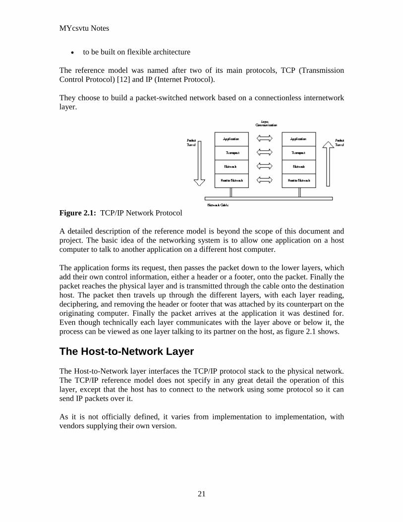
MYcsvtu Notes
21
to be built on flexible architecture
The reference model was named after two of its main protocols TCP (Transmission
Control Protocol) [12] and IP (Internet Protocol)
They choose to build a packet-switched network based on a connectionless internetwork
layer
Figure 21 TCPIP Network Protocol
A detailed description of the reference model is beyond the scope of this document and
project The basic idea of the networking system is to allow one application on a host
computer to talk to another application on a different host computer
The application forms its request then passes the packet down to the lower layers which
add their own control information either a header or a footer onto the packet Finally the
packet reaches the physical layer and is transmitted through the cable onto the destination
host The packet then travels up through the different layers with each layer reading
deciphering and removing the header or footer that was attached by its counterpart on the
originating computer Finally the packet arrives at the application it was destined for
Even though technically each layer communicates with the layer above or below it the
process can be viewed as one layer talking to its partner on the host as figure 21 shows
The Host-to-Network Layer
The Host-to-Network layer interfaces the TCPIP protocol stack to the physical network
The TCPIP reference model does not specify in any great detail the operation of this
layer except that the host has to connect to the network using some protocol so it can
send IP packets over it
As it is not officially defined it varies from implementation to implementation with
vendors supplying their own version
MYcsvtu Notes
22
The Network Layer
The job of the network layer is to inject packets into any network and have them travel
independently to the destination The layer defines IP (Internet Protocol) for its official
packet format and protocol Packet routing is a major job of this protocol
The Transport Layer
The transport layer is the interface between the application layer and the complex
hardware of the network It is designed to allow peer entities on the source and
destination hosts to carry on conversations
Data may be user data or control data Two modes are available full-duplex and half
duplex In full-duplex operation both sides can transmit and receive data simultaneously
whereas in half duplex a side can only send or receive at one time
Interaction between the transport layer and the layers immediately above and below are
shown in figure 22 Any program running in the application layer has the ability to send
a message using TCP or UDP which are the two protocols defined for the transport layer
The application can communicate with the TCP or the UDP service whichever it
requires Both the TCP and UDP communicate with the Internet Protocol in the internet
layer In all cases communication is a two way process The applications can read and
write to the transport layer The diagram only shows two protocols in the transport layer
TTCP will also reside in this layer between the other two protocols and function in the
same manner
Figure 22 Interaction with Application Transport and Internet Layers
A message to be sent originates in the application layer This is then passed down onto
the appropriate protocol in the transport layer These protocols add a header to the
message for the corresponding transport layer in the destination machine for purposes of
reassembling the message The segment is then passed onto the internet layer where the
Internet Protocol adds a further header Finally the segment is passed onto the physical
MYcsvtu Notes
23
layer a header and a trailer are added at this stage Figure 23 shows the structure of the
final segment being sent
Figure 23 Transmitted Segment from TCPIP Network
The Application Layer
The original TCPIP specification described a number of different applications that fit
into the top layer of the protocol stack These applications include Telnet FTP SMTP
and DNS
Telnet is a program that supports the TELNET [13] protocol over TCP TELNET is a
general two-way communication protocol that can be used to connect to another host and
run applications on that host remotely
FTP (File Transfer Protocol) [14] is a protocol that was originally designed to promote
the sharing of files among computer users It shields the user from the variations of file
storage on different architectures and allows for a reliable and efficient transfer of data
SMTP (Simple Mail Transport Protocol) [15] is the protocol used to transport electronic
mail from one computer to another through a series of other computers along the route
DNS [10] (Domain Name System) resolves the numerical address of a network node into
its textual name or vice-versa It would translate wwwyahoocom to 2047117771 to
allow the routing protocols to find the host that the packet is destined for
What is a Topology
The physical topology of a network refers to the configuration of cables computers and
other peripherals Physical topology should not be confused with logical topology which
is the method used to pass information between workstations Logical topology was
discussed in the Protocol chapter
Main Types of Physical Topologies
The following sections discuss the physical topologies used in networks and other related
topics
Linear Bus
MYcsvtu Notes
24
Star
Star-Wired Ring
Tree
Considerations When Choosing a Topology
Summary Chart
Linear Bus
A linear bus topology consists of a main run of cable with a terminator at each end (See
fig 1) All nodes (file server workstations and peripherals) are connected to the linear
cable Ethernet and LocalTalk networks use a linear bus topology
Fig 1 Linear Bus topology
Advantages of a Linear Bus Topology
Easy to connect a computer or peripheral to a linear bus
Requires less cable length than a star topology
Disadvantages of a Linear Bus Topology
Entire network shuts down if there is a break in the main cable
Terminators are required at both ends of the backbone cable
Difficult to identify the problem if the entire network shuts down
Not meant to be used as a stand-alone solution in a large building
Star
A star topology is designed with each node (file server workstations and peripherals)
connected directly to a central network hub or concentrator (See fig 2)
Data on a star network passes through the hub or concentrator before continuing to its
destination The hub or concentrator manages and controls all functions of the network It
also acts as a repeater for the data flow This configuration is common with twisted pair
cable however it can also be used with coaxial cable or fiber optic cable
MYcsvtu Notes
25
Fig 2 Star topology
Advantages of a Star Topology
Easy to install and wire
No disruptions to the network then connecting or removing devices
Easy to detect faults and to remove parts
Disadvantages of a Star Topology
Requires more cable length than a linear topology
If the hub or concentrator fails nodes attached are disabled
More expensive than linear bus topologies because of the cost of the
concentrators
The protocols used with star configurations are usually Ethernet or LocalTalk Token
Ring uses a similar topology called the star-wired ring
Star-Wired Ring
A star-wired ring topology may appear (externally) to be the same as a star topology
Internally the MAU (multistation access unit) of a star-wired ring contains wiring that
allows information to pass from one device to another in a circle or ring (See fig 3) The
Token Ring protocol uses a star-wired ring topology
Tree
A tree topology combines characteristics of linear bus and star topologies It consists of
groups of star-configured workstations connected to a linear bus backbone cable (See fig
MYcsvtu Notes
26
4) Tree topologies allow for the expansion of an existing network and enable schools to
configure a network to meet their needs
Fig 4 Tree topology
Advantages of a Tree Topology
Point-to-point wiring for individual segments
Supported by several hardware and software venders
Disadvantages of a Tree Topology
Overall length of each segment is limited by the type of cabling used
If the backbone line breaks the entire segment goes down
More difficult to configure and wire than other topologies
5-4-3 Rule
A consideration in setting up a tree topology using Ethernet protocol is the 5-4-3 rule
One aspect of the Ethernet protocol requires that a signal sent out on the network cable
reach every part of the network within a specified length of time Each concentrator or
repeater that a signal goes through adds a small amount of time This leads to the rule that
between any two nodes on the network there can only be a maximum of 5 segments
connected through 4 repeatersconcentrators In addition only 3 of the segments may be
populated (trunk) segments if they are made of coaxial cable A populated segment is one
which has one or more nodes attached to it In Figure 4 the 5-4-3 rule is adhered to The
MYcsvtu Notes
27
furthest two nodes on the network have 4 segments and 3 repeatersconcentrators
between them
This rule does not apply to other network protocols or Ethernet networks where all fiber
optic cabling or a combination of a fiber backbone with UTP cabling is used If there is a
combination of fiber optic backbone and UTP cabling the rule is simply translated to 7-
6-5 rule
] Mesh
Full
Fully Connected The type of network topology in which each of the nodes of the network is
connected to each of the other nodes in the network with a point-to-point link ndash
this makes it possible for data to be simultaneously transmitted from any single
node to all of the other nodes
Note The physical fully connected mesh topology is generally too costly and
complex for practical networks although the topology is used when there are only
a small number of nodes to be interconnected[3]
Partial
Partially Connected The type of network topology in which some of the nodes of the network are
connected to more than one other node in the network with a point-to-point link ndash
this makes it possible to take advantage of some of the redundancy that is
provided by a physical fully connected mesh topology without the expense and
complexity required for a connection between every node in the network
Note In most practical networks that are based upon the physical partially
connected mesh topology all of the data that is transmitted between nodes in the
network takes the shortest path between nodes except in the case of a failure or
break in one of the links in which case the data takes an alternate path to the
destination ndash this implies that the nodes of the network possess some type of
logical routing algorithm to determine the correct path to use at any particular
time
[edit] Hybrid Network Topologies
The hybrid topology is a type of network topology that is composed of one or more
interconnections of two or more networks that are based upon different physical
topologies or a type of network topology that is composed of one or more
interconnections of two or more networks that are based upon the same physical
topology but where the physical topology of the network resulting from such an
interconnection does not meet the definition of the original physical topology of the
interconnected networks (eg the physical topology of a network that would result from
an interconnection of two or more networks that are based upon the physical star
topology might create a hybrid topology which resembles a mixture of the physical star
MYcsvtu Notes
28
and physical bus topologies or a mixture of the physical star and the physical tree
topologies depending upon how the individual networks are interconnected while the
physical topology of a network that would result from an interconnection of two or more
networks that are based upon the physical distributed bus network retains the topology of
a physical distributed bus network)
Star-Bus A type of network topology in which the central nodes of one or more individual
networks that are based upon the physical star topology are connected together
using a common bus network whose physical topology is based upon the
physical linear bus topology the endpoints of the common bus being terminated
with the characteristic impedance of the transmission medium where required ndash
eg two or more hubs connected to a common backbone with drop cables
through the port on the hub that is provided for that purpose (eg a properly
configured uplink port) would comprise the physical bus portion of the physical
star-bus topology while each of the individual hubs combined with the
individual nodes which are connected to them would comprise the physical star
portion of the physical star-bus topology
Star-of-Stars
Hierarchical Star A type of network topology that is composed of an interconnection of individual
networks that are based upon the physical star topology connected together in a
hierarchical fashion to form a more complex network ndash eg a top level central
node which is the hub of the top level physical star topology and to which other
second level central nodes are attached as the spoke nodes each of which in
turn may also become the central nodes of a third level physical star topology
Notes 1) The physical hierarchical star topology is not a combination of the physical
linear bus and the physical star topologies as cited in some texts as there is no
common linear bus within the topology although the top level hub which is the
beginning of the physical hierarchical star topology may be connected to the
backbone of another network such as a common carrier which is topologically
not considered to be a part of the local network ndash if the top level central node is
connected to a backbone that is considered to be a part of the local network then
the resulting network topology would be considered to be a hybrid topology that
is a mixture of the topology of the backbone network and the physical hierarchical
star topology
2) The physical hierarchical star topology is also sometimes incorrectly referred
to as a physical tree topology since its physical topology is hierarchical however
the physical hierarchical star topology does not have a structure that is determined
by a branching factor as is the case with the physical tree topology and therefore
nodes may be added to or removed from any node that is the hub of one of the
individual physical star topology networks within a network that is based upon the
physical hierarchical star topology
3) The physical hierarchical star topology is commonly used in outside plant
(OSP) cabling to connect various buildings to a central connection facility which
MYcsvtu Notes
29
may also house the demarcation point for the connection to the data transmission
facilities of a common carrier and in inside plant (ISP) cabling to connect
multiple wiring closets within a building to a common wiring closet within the
same building which is also generally where the main backbone or trunk that
connects to a larger network if any enters the building
Star-wired Ring A type of hybrid physical network topology that is a combination of the physical
star topology and the physical ring topology the physical star portion of the
topology consisting of a network in which each of the nodes of which the network
is composed are connected to a central node with a point-to-point link in a hub
and spoke fashion the central node being the hub and the nodes that are
attached to the central node being the spokes (eg a collection of point-to-point
links from the peripheral nodes that converge at a central node) in a fashion that is
identical to the physical star topology while the physical ring portion of the
topology consists of circuitry within the central node which routes the signals on
the network to each of the connected nodes sequentially in a circular fashion
Note In an 8025 Token Ring network the central node is called a Multistation
Access Unit (MAU)
Hybrid Mesh A type of hybrid physical network topology that is a combination of the physical
partially connected topology and one or more other physical topologies the mesh
portion of the topology consisting of redundant or alternate connections between
some of the nodes in the network ndash the physical hybrid mesh topology is
commonly used in networks which require a high degree of availability
Considerations When Choosing a Topology
Money A linear bus network may be the least expensive way to install a network
you do not have to purchase concentrators
Length of cable needed The linear bus network uses shorter lengths of cable
Future growth With a star topology expanding a network is easily done by
adding another concentrator
Cable type The most common cable in schools is unshielded twisted pair which
is most often used with star topologies
Summary Chart
Common Cable Common Protocol
Linear Bus Twisted Pair
Coaxial
Ethernet
LocalTalk
MYcsvtu Notes
30
Fiber
Star Twisted Pair
Fiber
Ethernet
LocalTalk
Star-Wired Ring Twisted Pair Token Ring
Tree
Twisted Pair
Coaxial
Fiber
Ethernet
Internet vs Web
The Internet and the World Wide Web are not synonymous the Internet is a collection of
interconnected computer networks linked by copper wires fiber-optic cables wireless
connections etc the Web is a collection of interconnected documents and other
resources linked by hyperlinks and URLs The World Wide Web is accessible via the
Internet as are many other services including e-mail file sharing and others described
below
The best way to define and distinguish between these terms is to understand the Internet
protocol suite This collection of protocols is organized into layers such that each layer
provides the foundation and the services required by the layer above In this conception
the term Internet refers to computer networks that all communicate with IP (Internet
protocol) and TCP (transfer control protocol) Once this networking structure is
established then other protocols can run ―on top These other protocols are sometimes
called services or applications Hypertext transfer protocol or HTTP is an application
layer protocol that links billions of files together into the World Wide Web
Common uses of the Internet
The World Wide Web
Through keyword-driven Internet research using search engines like Google
millions worldwide have easy instant access to a vast and diverse amount of
online information Compared to encyclopedias and traditional libraries the
World Wide Web has enabled a sudden and extreme decentralization of
information and data
Many individuals and some companies and groups have adopted the use of Web logs or
blogs which are largely used as easily-updatable online diaries Some commercial
organizations encourage staff to fill them with advice on their areas of specialization in
the hope that visitors will be impressed by the expert knowledge and free information
and be attracted to the corporation as a result One example of this practice is Microsoft
MYcsvtu Notes
31
whose product developers publish their personal blogs in order to pique the publics
interest in their work
For more information on the distinction between the World Wide Web and the Internet
itself mdash as in everyday use the two are sometimes confused mdash see Dark internet where
this is discussed in more detail
Remote access
The Internet allows computer users to connect to other computers and information stores
easily wherever they may be across the world They may do this with or without the use
of security authentication and encryption technologies depending on the requirements
This is encouraging new ways of working from home collaboration and information
sharing in many industries An accountant sitting at home can audit the books of a
company based in another country on a server situated in a third country that is remotely
maintained by IT specialists in a fourth These accounts could have been created by
home-working book-keepers in other remote locations based on information e-mailed to
them from offices all over the world Some of these things were possible before the
widespread use of the Internet but the cost of private leased lines would have made
many of them infeasible in practice
An office worker away from his desk perhaps the other side of the world on a business
trip or a holiday can open a remote desktop session into his normal office PC using a
secure Virtual Private Network (VPN) connection via the Internet This gives him
complete access to all his normal files and data including e-mail and other applications
while he is away
This concept is also referred to by some network security people as the Virtual Private
Nightmare because it extends the secure perimeter of a corporate network into its
employees homes this has been the source of some notable security breaches but also
provides security for the workers
Functions
File-sharing
Instant messaging
Internet fax
Search engine
World Wide Web
MYcsvtu Notes
32
Intranets
What are Intranets
bull Intranet is Intra+ Net so an Intranet is an internal or private Internet used strictly
within the confines of a company university or organization Inter means
between or among hence the difference between the Internet and an Intranet
Some formal definitions of Intranets
bull Brown amp Duguid ―Intranets help present and
circulate boundary objects
bull Choo Detlor amp Turnbull ―Intranetshellip support the creation sharing and use of
knowledge
bull Stenmark ―Intranets are organizationally
restricted
A technical definition
bull An Intranet is a network based on the internet TCPIP open standard An intranet
belongs to an organization and is designed to be accessible only by the
organizations members employees or others with authorization An intranets
Web site looks and act just like other Web sites but has a firewall surrounding it
to fend off unauthorized users
Design Of Intranets
Steps
bull Analyze the organizationlsquos information ecology
bull Identify the typical problems experienced by users
bull Analyze the information behaviors of these set of users
bull Create value added processes to resolve the problems of users and to improve the
Information Ecology
Value Added Processes
bull Intranets may be designed to improve the organizational information ecology
MYcsvtu Notes
33
bull Intranets provide a unified information space in which users can communicate
and collaborate with others
bull intranet applications and services may add value by supporting the organizationlsquos
knowledge creating and decision making process
Two Models of Online Environments
Centralized
Distributed
Centralized Environments
bull Before the web the centralized model was all we had (examples include
CompuServe Prodigy)
bull On the web centralized models include site-based services such as Yahoo
bull Most (all) college and university services are offered using the centralized
model
MYcsvtu Notes
34
bull But centralized environments are static inflexible expensive
Distributed Environments
bull The World Wide Web is an example of a distributed environment
bull Resources access are not centralized but scattered around the world
ndash Resources in the form of a network of connected (via DNS) web servers
ndash Access in the form of a network of connected (via DNS) internet service
providers
ndash Users in the form of individualized and connected (via HTTP) web
browsers
bull The big issue ndash integration ndash that is making different systems work together
Design Principles
Network Design Principles
ndash Specifies how networks differ from traditional learning
ndash The idea is that each principle confers an advantage over non-network
systems
ndash Can be used as a means of evaluating new technology
1 Decentralize
ndash Centralized networks have a characteristic starlsquo shape
bull Some entities have many connections
bull The vast majority have few
bull Eg broadcast network teacher in a classroom
ndash Decentralized networks form a mesh
bull The weight of connections flow is distributed
bull Balanced load = more stable
bull Foster connections between entities fill outlsquo the star
Distribute
ndash Network entities reside in different physical locations
bull Reduces risk of network failure
bull Reduces need for major infrastructure such as powerful servers
large bandwidth massive storage
ndash Examples
bull Peer-to-peer networks such as Kazaa Gnutella
bull Content syndication networks such as RSS
ndash Emphasis is on sharing not copying
bull Locallsquo copies are temporary
MYcsvtu Notes
35
Computer Graphics
Computer Graphics is about animation (films)
Games are very important in Computer Graphics
Medical Imaging is another driving force
Computer Aided Design too
Graphics Definitions
bull Point
ndash a location in space 2D or 3D
ndash sometimes denotes one pixel
bull Line
ndash straight path connecting two points
ndash infinitesimal width consistent density
ndash beginning and end on points
bull Vertex
ndash point in 3D
bull Edge
ndash line in 3D connecting two vertices
bull PolygonFaceFacet
ndash arbitrary shape formed by connected vertices
ndash fundamental unit of 3D computer graphics
bull Raster
ndash derived from TV systems for a row of pixels
ndash commonly referred to as a scanline
ndash does influence algorithms ndash reducing memory requirements parallelism
etc
ndash is the derivation of rasterization scan-line algorithms
Displays
bull Most desktop displays use a cathode ray tube (CRT) while portable computing
devices such as laptops incorporate liquid crystal display (LCD)
bull Because of their slimmer design and smaller energy consumption monitors using
LCD technologies are beginning to replace the venerable CRT on many desktops
Cathode-Ray Tubes
MYcsvtu Notes
36
bull Classical output device is a monitor
bull Cathode-Ray Tube (CRT)
ndash Invented by Karl Ferdinand Braun (1897)
ndash Beam of electrons directed from cathode (-)to phosphor-coated
(fluorescent) screen (anode (+))
ndash Directed by magnetic focusing and deflection coils (anodes) in vacuum
filled tube
ndash Phosphor emits photon of light when hit by an electron of varied
persistence (long 15-20 ms for texts short lt 1ms for animation)
ndash Refresh rate (50-60 Hz 72-76 Hz) to avoid flicker trail
ndash Phosphors are organic compounds characterized by their persistence and
their color (blue red green)
Cathode-Ray Tubes
bull Cathode-Ray Tube (CRT)
ndash Horizontal deflection and vertical deflection direct the electron beam to
any point on the screen
ndash Intensity knob regulates the flow of electrons by controlling the voltage at
the control grid (high voltage reduces the electron density and thus
brightness)
ndash Accelerating voltage from positive coating inside screen (anode screen) or
an accelerating anode
bull Image maintenance
ndash Charge distribution to store picture information
OR
ndash Refresh CRT refreshes the display constantly to maintain phosphor glow
Cathode-Ray Tubes
bullCathode-Ray Tube (CRT)
ndash Horizontal deflection and vertical deflection direct the electron beam to any point
on the screen
ndash Intensity knob regulates the flow of electrons by controlling the voltage at the
control grid (high voltage reduces the electron density and thus brightness)
ndash Accelerating voltage from positive coating inside screen (anode screen) or an
accelerating anode
bullImage maintenance
ndash Charge distribution to store picture information
OR
ndash Refresh CRT refreshes the display constantly to maintain phosphor glow
bull Characteristics of Cathode-Ray Tube (CRT)
MYcsvtu Notes
37
ndash Intensity is proportional to the number of electrons repelled in beam per
second (brightness)
ndash Resolution is the maximum number of points that can be displayed
without overlap is expressed as number of horizontal points by number of
vertical points points are called pixels (picture elements) example
resolution 1024 x 768 pixels Typical resolution is 1280 x 1024 pixels
bull High-definition systems high resolution systems
bull Focusing
ndash Focusing forces the electron beam to converge to a point on the monitor
screen
ndash Can be electrostatic (lens) or magnetic (field)
bull Deflection
ndash Deflection directs the electron beam horizontally andor vertically to any
point on the screen
ndash Can be controlled by electric (deflection plates slide 9) or magnetic fields
(deflection coils slide 5)
ndash Magnetic coils two pairs (topbottom leftright) of tube neck
ndash Electric plates two pairs (horizontal vertical)
Raster-scan Displays
bullVideo displays can be either raster-scan or random-scan displays
bullRaster-scan display is the most common type of monitor using a CRT
bullThe electron beam scans the screen from top to bottom one row at a time Each row is
called a scan line
bullThe electron beam is turned on and off to produce a collection of dots painted one row at
a time These will form the image
bullA raster is a matrix of pixels covering the screen area and is composed of raster lines
Raster-scan Displays
MYcsvtu Notes
38
Raster-scan Displays
bullThe image is stored in a frame buffer containing the total screen area and where each
memory location corresponds to a pixel
bullIn a monochrome system each bit is 1 or 0 for the corresponding pixel to be on or off
(bitmap)
bullThe display processor scans the frame buffer to turn electron beam onoff depending if
the bit is 1 or 0
bullFor color monitors the frame buffer also contains the color of each pixel (color buffer)
as well as other characteristics of the image (gray scale hellip) 8 bitspixel 0255
(pixmap)
bullDepth of the buffer area is the number of bits per pixel (bit planes) up to 24
bullExamples television panels printers PC monitors (99 of raster-scan)
Raster-scan Displays
bullRefresh rate 24 is a minimum to avoid flicker corresponding to 24 Hz (1 Hz = 1 refresh
per second)
bullCurrent raster-scan displays have a refresh rate of at least 60 frames (60 Hz) per second
up to 120 (120 Hz)
bullUses large memory 640x480 307200 bits 38 kB
bullRefresh procedure
MYcsvtu Notes
39
ndashHorizontal retrace ndash beam returns to left of screen
ndashVertical retrace ndash bean returns to top left corner of screen
ndashInterlaced refresh ndash display first even-numbered lines then odd-numbered lines
permits to see the image in half the time
useful for slow refresh rates (30 Hz shows as 60 Hz)
Random-scan Displays
bullRandom scan systems are also called vector stroke-writing or calligraphic displays
bullThe electron beam directly draws the picture in any specified order
bullA pen plotter is an example of such a system
bullPicture is stored in a display list refresh display file vector file or display program as a
set of line drawing commands
bullRefreshes by scanning the list 30 to 60 times per second
bullMore suited for line-drawing applications such as architecture and manufacturing
Random-scan Displays
bullAdvantages
ndashHigh resolution
ndashEasy animation
ndashRequires little memory
bullDisadvantages
ndashRequires intelligent electron beam (processor controlled)
ndashLimited screen density limited to simple line-based images
ndashLimited color capability
bullImproved in the 1960lsquos by the Direct View Storage Tube (DVST) from Tektronix
Color CRT Monitor
Uses different phosphors a combination of Red Green and Blue to produce any color
Two methods
Random scan uses beam penetration
2 layers (Red Green) phosphors low speed electrons excite Red high speed electrons
excite Green interrmediate speed excite both to get yellow and orange Color is
controlled by electron beam voltage
Only produces a restricted set of colors
Raster scan uses a shadow mask with three electron guns Red Green and Blue (RGB
color model) Color is produced by adjusting the intensity level of each electron beam
Produces a wide range of colors from 8 to several millions
Raster scan
Most common as found in televisions
Beam scanned left to right flicked back to rescan from top to bottom then repeated
Repeated at 30Hz per frame sometimes higher to reduce flicker Interlacing scanning
MYcsvtu Notes
40
odd lines in whole screen then even lines is also used to reduce flicker Can also use
high-persistence phosphor to reduce flicker but causes image smearing especially with
significant animation
Resolution typically 512x512 but high-quality screens are available (and becoming more
common) at up to approximately 1600x1200 pixels Sun workstations have screens of
1192x980 pixels
Black amp white screens can display grayscale by varying the intensity of the electron
beam
Colour is achieved using three electron guns which hit red green or blue phosphors
Combining these colours can produce many others including white (all on) Phosphor
dots focused using a shadow mask - makes colour screens lower resolution than
monochrome
Alternative approach beam penetration Special phosphor glows a different colour
depending on intensity of beam
Colour or intensity at pixel held by computerlsquos video card 1 bitpixel can store offon
information hence only black ampwhite More bitspixel give rise to more colour
possibilities eg 8 bitspixel gives rise to 2^8=256 possible colours at any one time
Random Scan (Directed-beam refresh vector display)
Instead of scanning the whole display sequentially and horizontally the random scan
draws the lines to be displayed directly Screen update at gt30Hz to reduce flicker
Jaggies not found and higher resolutions possible (up to 4096x4096 pixels) Colour
achieved using beam penetration generally of poorer quality Eye strain and fatigue still
a problem and vector displays are more expensive
Direct view storage tube (DVST)
Used a lot in analogue storage oscilloscopes
Similar to random scan crt but image maintained by flood guns - no flicker Can be
incrementally updated but not selectively erased image has to be redrawn on completely
erased screen High resolution (typically 4096x3120 pixels) but low contrast low
brightness and difficulty in displaying colour
What is a Multimedia System
bull A system that involves
ndash generation
ndash representation
ndash storage
ndash transmission
ndash search and retrieval
ndash delivery
MYcsvtu Notes
41
of multimedia information
productionauthoring tools
compression and formats
file system design
networking issues
database management
server design streaming
Multimedia System Architecture
Information management subsystem Presentation Query
Storage subsystem Efficiently stored
amp retrieved
Network subsystem Delivery
Adaptation in Multimedia Systems
bull Multimedia systems can profit a lot from personalization
ndash User behavior
ndash User properties
bull Adaptation
ndash Models
ndash Mechanisms
Multimedia in a mobile environment
MYcsvtu Notes
42
bull Applications
ndash Emergency response systems mobile commerce phone service
entertainment games
What is Sound
A ripple is a pressure wave in water created by an object striking the water
Sound is a pressure wave in air created for example by an object such as a string
or our vocal cords vibrating Dark here represents more pressure light represents
less
MYcsvtu Notes
43
Sine Waves Form Pure Tones
This simple sound wave is a Sine Wave a Pure tone produced by a simple vibration
Sine Wave Sample Tone
This can be represented graphically as shown above
Converting Pressure into Voltage
The pressure wave of sound moves a diaphragm in the microphone which produces a
voltage proportional to the pressure of the sound wave at each instant
Animation
MYcsvtu Notes
44
bull Animation is the rapid display of a sequence of images of 2-D artwork or model
positions in order to create an illusion of movement It is an optical illusion of
motion due to the phenomenon of persistence of vision This could be anything
from a flip book to a motion picture film Animation deals with the generation
sequencing and display a set of images which is called frames to create an effect
of visual change or motion similar to a movie film
bull Animation is used in those instance where videography is not possible
Hardware Requirement For Animation
bull Image Generation Tools amp Devices
bull Computer monitors with image display Capability
Software Requirement For Animation
bull Animation creating software
bull Screen Capture Software
bull Animation Clips
bull Software support For High Resolution
bull Recording amp Playback Capability
bull Transition effect
Early animation
There is no single person that can be considered the creator of the art of animation as
there were several people doing several projects which could be considered various types
of animation all around the same time (Short hand-drawn animation scenes could be
presented with the Phenakistoscope the Zoetrope and other optical toys already in the
early 1800s)
The following is a brief listing on those who are often acknowledged as significant to the
development of animation Note that this list is by no means a comprehensive list of
contributors to early animation
Georges Meacuteliegraves was a creator of special effect films such as A Trip to the Moon He
used many techniques ndash one of which was to stop the camera rolling change something
in the scene and then continue rolling the film This is a very similar idea to that of stop-
motion animation Meacuteliegraves accidentally happened upon the technique when his camera
broke down while shooting a bus driving by When the camera was fixed a horse
happened to be passing by just as Meacuteliegraves continued to film The result was that the bus
appeared to change into a horse
MYcsvtu Notes
45
Fantasmagorie by Emile Cohl 1908
Eacutemile Cohl began drawing cartoon strips and created a film in 1908 called
Fantasmagorie The film largely consisted of a stick figure moving about and
encountering all manner of morphing objects such as a wine bottle that transforms into a
flower There were also sections of live action where the animatorlsquos hands would enter
the scene The film was created by drawing each frame on paper and then shooting each
frame onto negative film which gave the picture a blackboard look
Winsor McCay created detailed animations that required a team of artists and painstaking
attention for detail Each frame was drawn on paper requiring backgrounds to be
redrawn as well characters to be animated His films such as Gertie the Dinosaur (1914)
and The Sinking of the Lusitania (1918) were of an impressive scale although The
Sinking of the Lusitania used cels
In 1919 Otto Messmer created the character of Felix the cat for Pat Sullivans animation
studios The importance of Felix lies in the characters strong personality created largely
through gesture and actions
Animation techniques
Animation techniques are incredibly varied and difficult to categorize Techniques are
often related or combined The following is a brief on common types of animation
Again this list is by no means comprehensive
Traditional animation
An example of traditional animation a horse animated by rotoscoping from Edweard
Muybridges 19th century photos
Main article Traditional animation
MYcsvtu Notes
46
Also called cel animation the frames of a traditionally animated movie are hand-drawn
The drawings are traced or copied onto transparent acetate sheets called cels which are
then placed over a painted background and photographed one by one on a rostrum
camera Nowadays the use of cels (and cameras) is mostly obsolete since the drawings
are scanned into computers and digitally transferred directly to 35 mm film The look
of traditional cel animation is still preserved and the character animators work has
remained essentially the same over the past 70 years Because of the digital influence
over modern cel animation it is also known as tradigital animation
Examples The Lion King Spirited Away Les Triplettes de Belleville
Full animation The most common style in animation known for its realistic and often very detailed art
Examples All Disney feature length animated films The Secret of NIMH The Iron Giant
Limited animation A cheaper process of making animated cartoons that does not follow a realistic
approach
Examples The Flintstones Yellow Submarine
Rubber hose The characters are usually cartoony and the animators have a lot of artistic freedom as
rubber hose animations dont have to follow the laws of physics and anatomy in the same
degree as the other main styles in animation
Examples Early Mickey Mouse cartoons Ren and Stimpy Popeye
Rotoscoping A technique where animators trace live action movement frame by frame for use in
animated films
Examples Gullivers Travels American Pop
Stop motion
Stop-motion animation is any type of animation which requires the animator to physically
alter the scene shoot a frame again alter the scene and shoot a frame and so on to create
the animation There are many different types of stop-motion animation some noteable
examples are listed below
Clay animation
MYcsvtu Notes
47
A clay animation scene from a TV commercial
Often abbreviated to claymation this is a type of stop-motion animation using
figures made of clay or a similar malleable material The figures may have an
armature or wire frame inside of them similar to puppet animation (below)
Alternatively the figures may be made entirely of clay such as in the films of
Bruce Bickford where clay creatures morph into a variety of different shapes
Examples Wallace and Gromit Dimensions of Dialogue by Jan Švankmajer The
Amazing Mr Bickford The Trap Door
Cutout animation In this type of stop-motion animation the animation is formed by moving 2-
dimensional pieces of material such as paper or cloth
Examples the animated sequences of Monty Pythons Flying Circus (often
referred to as Dada animation named after the Dada art movement[citation needed]
)
Tale of Tales early episodes of South Park
Silhouette animation A type of cutout animation where the viewer only sees black silhouettes
Example The Adventures of Prince Achmed the worlds oldest surviving
animated feature film from 1926
Graphic animation
Model animation In this form of animation model animated characters interact with and are a part
of the live-action world
Examples The films of Ray Harryhausen (Jason and the Argonauts) and Willis
OBrien (King Kong)
Go motion
Object animation
Pixilation Examples Neighbours
Puppet animation Puppet animation typically involves puppet figures interacting with each other in
a constructed environment in contrast to the real-world interaction in model
MYcsvtu Notes
48
animation (above) The puppets generally have an armature inside of them to
keep them still and steady as well as constraining them to move at particular
joints
Examples The Nightmare Before Christmas Robot Chicken The Tale of the Fox
Brickfilm
Puppetoon
Computer animation
A short gif animation
Like stop motion computer animation encompasses a variety of techniques the unifying
idea being that the animation is created digitally on a computer
2D animation Figures are created andor edited on the computer using 2D bitmap graphics or
created and edited using 2D vector graphics This includes automated
computerized versions of traditional animation techniques such as of tweening
morphing onion skinning and interpolated rotoscoping
Examples A Scanner Darkly Jib Jab
Analog computer animation
Flash animation
PowerPoint animation
A completely synthetic computer-generated scene
3D animation
MYcsvtu Notes
49
Figures are created in the computer using polygons To allow these meshes to
move they are given a digital armature (sculpture) This process is called rigging
Various other techniques can be applied such as mathematical functions
(gravity) simulated fur or hair effects such as fire and water and the use of
motion capture to name but a few
Examples The Incredibles Shrek
Cel-shaded animation
Morph target animation
Skeletal animation
Motion capture
Crowd simulation
Less common techniques
Drawn on film animation A technique where footage is produced by creating the
images directly on film stock
Paint-on-glass animationA technique for making animated films by manipulating slow-
drying oil paints on sheets of glass
Pinscreen animation Makes use of a screen filled with movable pins which can be
moved in or out by pressing an object onto the screen The screen is lit from the side so
that the pins cast shadows The technique has been used to create animated films with a
range of textural effects difficult to achieve with traditional cel animation
Sand animation Sand is moved around on a backlighted or frontlighted piece of glass to
create each frame for an animated film
Multimedia
Multimedia (Lat Multum + Medium) is media that uses multiple forms of information
content and information processing (eg text audio graphics animation video
interactivity) to inform or entertain the (user) audience Multimedia also refers to the use
of (but not limited to) electronic media to store and experience multimedia content
Multimedia is similar to traditional mixed media in fine art but with a broader scope The
term rich media is synonymous for interactive multimedia
Categorization
Multimedia may be broadly divided into linear and non-linear categories Linear active
content progresses without any navigation control for the viewer such as a cinema
presentation Non-linear content offers user interactivity to control progress as used with
MYcsvtu Notes
50
a computer game or used in self-paced computer based training Non-linear content is
also known as hypermedia content
Multimedia presentations can be live or recorded A recorded presentation may allow
interactivity via a navigation system A live multimedia presentation may allow
interactivity via interaction with the presenter or performer
There are 2 basic way to represent some information
Unimedium Presentation
Multimedia Presentation
In case of computer system the commonly used medioa for the purpose of storage
access and transmission of information are
bull Text
bull Graphics
bull Animation
bull Audio
bull Video
Multimedia Computer System require
bull Faster CPU
bull Larger Storage Devices
bull Larger Main Memory
bull Good Graphics Terminal
bull IO devices required to play an audio associated with the program
Transmission Mode
bull Asynchronous
bull Synchronous
bull Isochronous
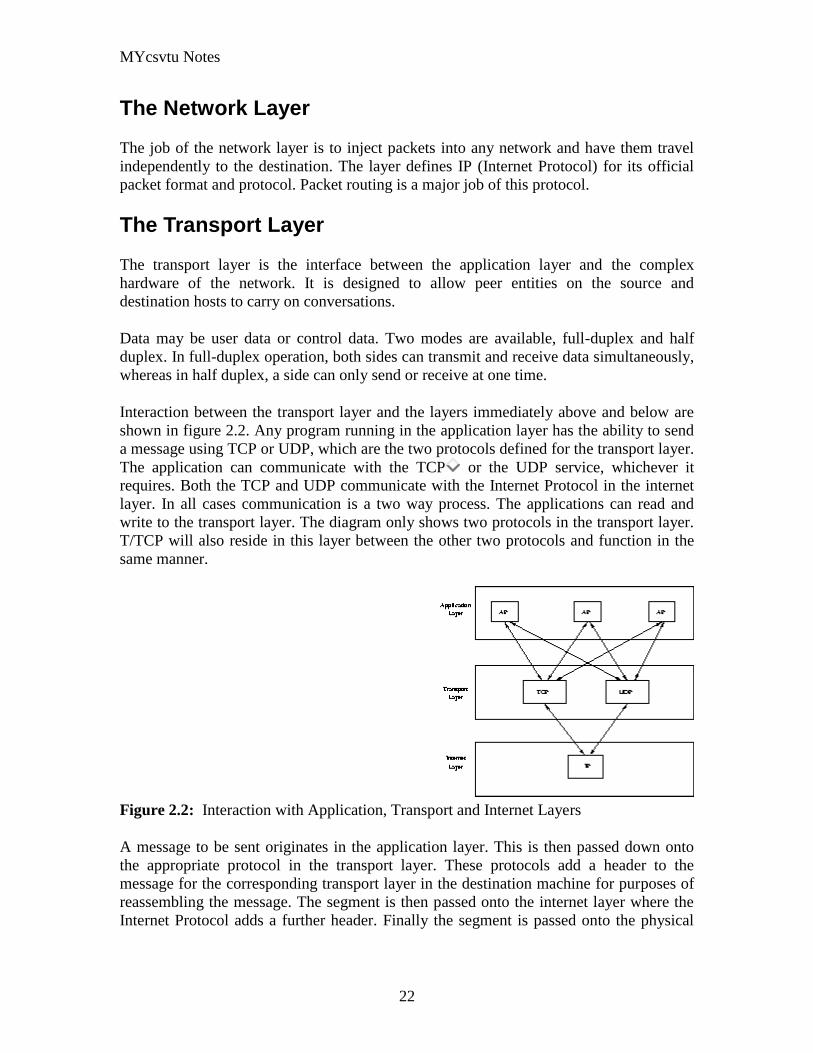
MYcsvtu Notes
22
The Network Layer
The job of the network layer is to inject packets into any network and have them travel
independently to the destination The layer defines IP (Internet Protocol) for its official
packet format and protocol Packet routing is a major job of this protocol
The Transport Layer
The transport layer is the interface between the application layer and the complex
hardware of the network It is designed to allow peer entities on the source and
destination hosts to carry on conversations
Data may be user data or control data Two modes are available full-duplex and half
duplex In full-duplex operation both sides can transmit and receive data simultaneously
whereas in half duplex a side can only send or receive at one time
Interaction between the transport layer and the layers immediately above and below are
shown in figure 22 Any program running in the application layer has the ability to send
a message using TCP or UDP which are the two protocols defined for the transport layer
The application can communicate with the TCP or the UDP service whichever it
requires Both the TCP and UDP communicate with the Internet Protocol in the internet
layer In all cases communication is a two way process The applications can read and
write to the transport layer The diagram only shows two protocols in the transport layer
TTCP will also reside in this layer between the other two protocols and function in the
same manner
Figure 22 Interaction with Application Transport and Internet Layers
A message to be sent originates in the application layer This is then passed down onto
the appropriate protocol in the transport layer These protocols add a header to the
message for the corresponding transport layer in the destination machine for purposes of
reassembling the message The segment is then passed onto the internet layer where the
Internet Protocol adds a further header Finally the segment is passed onto the physical
MYcsvtu Notes
23
layer a header and a trailer are added at this stage Figure 23 shows the structure of the
final segment being sent
Figure 23 Transmitted Segment from TCPIP Network
The Application Layer
The original TCPIP specification described a number of different applications that fit
into the top layer of the protocol stack These applications include Telnet FTP SMTP
and DNS
Telnet is a program that supports the TELNET [13] protocol over TCP TELNET is a
general two-way communication protocol that can be used to connect to another host and
run applications on that host remotely
FTP (File Transfer Protocol) [14] is a protocol that was originally designed to promote
the sharing of files among computer users It shields the user from the variations of file
storage on different architectures and allows for a reliable and efficient transfer of data
SMTP (Simple Mail Transport Protocol) [15] is the protocol used to transport electronic
mail from one computer to another through a series of other computers along the route
DNS [10] (Domain Name System) resolves the numerical address of a network node into
its textual name or vice-versa It would translate wwwyahoocom to 2047117771 to
allow the routing protocols to find the host that the packet is destined for
What is a Topology
The physical topology of a network refers to the configuration of cables computers and
other peripherals Physical topology should not be confused with logical topology which
is the method used to pass information between workstations Logical topology was
discussed in the Protocol chapter
Main Types of Physical Topologies
The following sections discuss the physical topologies used in networks and other related
topics
Linear Bus
MYcsvtu Notes
24
Star
Star-Wired Ring
Tree
Considerations When Choosing a Topology
Summary Chart
Linear Bus
A linear bus topology consists of a main run of cable with a terminator at each end (See
fig 1) All nodes (file server workstations and peripherals) are connected to the linear
cable Ethernet and LocalTalk networks use a linear bus topology
Fig 1 Linear Bus topology
Advantages of a Linear Bus Topology
Easy to connect a computer or peripheral to a linear bus
Requires less cable length than a star topology
Disadvantages of a Linear Bus Topology
Entire network shuts down if there is a break in the main cable
Terminators are required at both ends of the backbone cable
Difficult to identify the problem if the entire network shuts down
Not meant to be used as a stand-alone solution in a large building
Star
A star topology is designed with each node (file server workstations and peripherals)
connected directly to a central network hub or concentrator (See fig 2)
Data on a star network passes through the hub or concentrator before continuing to its
destination The hub or concentrator manages and controls all functions of the network It
also acts as a repeater for the data flow This configuration is common with twisted pair
cable however it can also be used with coaxial cable or fiber optic cable
MYcsvtu Notes
25
Fig 2 Star topology
Advantages of a Star Topology
Easy to install and wire
No disruptions to the network then connecting or removing devices
Easy to detect faults and to remove parts
Disadvantages of a Star Topology
Requires more cable length than a linear topology
If the hub or concentrator fails nodes attached are disabled
More expensive than linear bus topologies because of the cost of the
concentrators
The protocols used with star configurations are usually Ethernet or LocalTalk Token
Ring uses a similar topology called the star-wired ring
Star-Wired Ring
A star-wired ring topology may appear (externally) to be the same as a star topology
Internally the MAU (multistation access unit) of a star-wired ring contains wiring that
allows information to pass from one device to another in a circle or ring (See fig 3) The
Token Ring protocol uses a star-wired ring topology
Tree
A tree topology combines characteristics of linear bus and star topologies It consists of
groups of star-configured workstations connected to a linear bus backbone cable (See fig
MYcsvtu Notes
26
4) Tree topologies allow for the expansion of an existing network and enable schools to
configure a network to meet their needs
Fig 4 Tree topology
Advantages of a Tree Topology
Point-to-point wiring for individual segments
Supported by several hardware and software venders
Disadvantages of a Tree Topology
Overall length of each segment is limited by the type of cabling used
If the backbone line breaks the entire segment goes down
More difficult to configure and wire than other topologies
5-4-3 Rule
A consideration in setting up a tree topology using Ethernet protocol is the 5-4-3 rule
One aspect of the Ethernet protocol requires that a signal sent out on the network cable
reach every part of the network within a specified length of time Each concentrator or
repeater that a signal goes through adds a small amount of time This leads to the rule that
between any two nodes on the network there can only be a maximum of 5 segments
connected through 4 repeatersconcentrators In addition only 3 of the segments may be
populated (trunk) segments if they are made of coaxial cable A populated segment is one
which has one or more nodes attached to it In Figure 4 the 5-4-3 rule is adhered to The
MYcsvtu Notes
27
furthest two nodes on the network have 4 segments and 3 repeatersconcentrators
between them
This rule does not apply to other network protocols or Ethernet networks where all fiber
optic cabling or a combination of a fiber backbone with UTP cabling is used If there is a
combination of fiber optic backbone and UTP cabling the rule is simply translated to 7-
6-5 rule
] Mesh
Full
Fully Connected The type of network topology in which each of the nodes of the network is
connected to each of the other nodes in the network with a point-to-point link ndash
this makes it possible for data to be simultaneously transmitted from any single
node to all of the other nodes
Note The physical fully connected mesh topology is generally too costly and
complex for practical networks although the topology is used when there are only
a small number of nodes to be interconnected[3]
Partial
Partially Connected The type of network topology in which some of the nodes of the network are
connected to more than one other node in the network with a point-to-point link ndash
this makes it possible to take advantage of some of the redundancy that is
provided by a physical fully connected mesh topology without the expense and
complexity required for a connection between every node in the network
Note In most practical networks that are based upon the physical partially
connected mesh topology all of the data that is transmitted between nodes in the
network takes the shortest path between nodes except in the case of a failure or
break in one of the links in which case the data takes an alternate path to the
destination ndash this implies that the nodes of the network possess some type of
logical routing algorithm to determine the correct path to use at any particular
time
[edit] Hybrid Network Topologies
The hybrid topology is a type of network topology that is composed of one or more
interconnections of two or more networks that are based upon different physical
topologies or a type of network topology that is composed of one or more
interconnections of two or more networks that are based upon the same physical
topology but where the physical topology of the network resulting from such an
interconnection does not meet the definition of the original physical topology of the
interconnected networks (eg the physical topology of a network that would result from
an interconnection of two or more networks that are based upon the physical star
topology might create a hybrid topology which resembles a mixture of the physical star
MYcsvtu Notes
28
and physical bus topologies or a mixture of the physical star and the physical tree
topologies depending upon how the individual networks are interconnected while the
physical topology of a network that would result from an interconnection of two or more
networks that are based upon the physical distributed bus network retains the topology of
a physical distributed bus network)
Star-Bus A type of network topology in which the central nodes of one or more individual
networks that are based upon the physical star topology are connected together
using a common bus network whose physical topology is based upon the
physical linear bus topology the endpoints of the common bus being terminated
with the characteristic impedance of the transmission medium where required ndash
eg two or more hubs connected to a common backbone with drop cables
through the port on the hub that is provided for that purpose (eg a properly
configured uplink port) would comprise the physical bus portion of the physical
star-bus topology while each of the individual hubs combined with the
individual nodes which are connected to them would comprise the physical star
portion of the physical star-bus topology
Star-of-Stars
Hierarchical Star A type of network topology that is composed of an interconnection of individual
networks that are based upon the physical star topology connected together in a
hierarchical fashion to form a more complex network ndash eg a top level central
node which is the hub of the top level physical star topology and to which other
second level central nodes are attached as the spoke nodes each of which in
turn may also become the central nodes of a third level physical star topology
Notes 1) The physical hierarchical star topology is not a combination of the physical
linear bus and the physical star topologies as cited in some texts as there is no
common linear bus within the topology although the top level hub which is the
beginning of the physical hierarchical star topology may be connected to the
backbone of another network such as a common carrier which is topologically
not considered to be a part of the local network ndash if the top level central node is
connected to a backbone that is considered to be a part of the local network then
the resulting network topology would be considered to be a hybrid topology that
is a mixture of the topology of the backbone network and the physical hierarchical
star topology
2) The physical hierarchical star topology is also sometimes incorrectly referred
to as a physical tree topology since its physical topology is hierarchical however
the physical hierarchical star topology does not have a structure that is determined
by a branching factor as is the case with the physical tree topology and therefore
nodes may be added to or removed from any node that is the hub of one of the
individual physical star topology networks within a network that is based upon the
physical hierarchical star topology
3) The physical hierarchical star topology is commonly used in outside plant
(OSP) cabling to connect various buildings to a central connection facility which
MYcsvtu Notes
29
may also house the demarcation point for the connection to the data transmission
facilities of a common carrier and in inside plant (ISP) cabling to connect
multiple wiring closets within a building to a common wiring closet within the
same building which is also generally where the main backbone or trunk that
connects to a larger network if any enters the building
Star-wired Ring A type of hybrid physical network topology that is a combination of the physical
star topology and the physical ring topology the physical star portion of the
topology consisting of a network in which each of the nodes of which the network
is composed are connected to a central node with a point-to-point link in a hub
and spoke fashion the central node being the hub and the nodes that are
attached to the central node being the spokes (eg a collection of point-to-point
links from the peripheral nodes that converge at a central node) in a fashion that is
identical to the physical star topology while the physical ring portion of the
topology consists of circuitry within the central node which routes the signals on
the network to each of the connected nodes sequentially in a circular fashion
Note In an 8025 Token Ring network the central node is called a Multistation
Access Unit (MAU)
Hybrid Mesh A type of hybrid physical network topology that is a combination of the physical
partially connected topology and one or more other physical topologies the mesh
portion of the topology consisting of redundant or alternate connections between
some of the nodes in the network ndash the physical hybrid mesh topology is
commonly used in networks which require a high degree of availability
Considerations When Choosing a Topology
Money A linear bus network may be the least expensive way to install a network
you do not have to purchase concentrators
Length of cable needed The linear bus network uses shorter lengths of cable
Future growth With a star topology expanding a network is easily done by
adding another concentrator
Cable type The most common cable in schools is unshielded twisted pair which
is most often used with star topologies
Summary Chart
Common Cable Common Protocol
Linear Bus Twisted Pair
Coaxial
Ethernet
LocalTalk
MYcsvtu Notes
30
Fiber
Star Twisted Pair
Fiber
Ethernet
LocalTalk
Star-Wired Ring Twisted Pair Token Ring
Tree
Twisted Pair
Coaxial
Fiber
Ethernet
Internet vs Web
The Internet and the World Wide Web are not synonymous the Internet is a collection of
interconnected computer networks linked by copper wires fiber-optic cables wireless
connections etc the Web is a collection of interconnected documents and other
resources linked by hyperlinks and URLs The World Wide Web is accessible via the
Internet as are many other services including e-mail file sharing and others described
below
The best way to define and distinguish between these terms is to understand the Internet
protocol suite This collection of protocols is organized into layers such that each layer
provides the foundation and the services required by the layer above In this conception
the term Internet refers to computer networks that all communicate with IP (Internet
protocol) and TCP (transfer control protocol) Once this networking structure is
established then other protocols can run ―on top These other protocols are sometimes
called services or applications Hypertext transfer protocol or HTTP is an application
layer protocol that links billions of files together into the World Wide Web
Common uses of the Internet
The World Wide Web
Through keyword-driven Internet research using search engines like Google
millions worldwide have easy instant access to a vast and diverse amount of
online information Compared to encyclopedias and traditional libraries the
World Wide Web has enabled a sudden and extreme decentralization of
information and data
Many individuals and some companies and groups have adopted the use of Web logs or
blogs which are largely used as easily-updatable online diaries Some commercial
organizations encourage staff to fill them with advice on their areas of specialization in
the hope that visitors will be impressed by the expert knowledge and free information
and be attracted to the corporation as a result One example of this practice is Microsoft
MYcsvtu Notes
31
whose product developers publish their personal blogs in order to pique the publics
interest in their work
For more information on the distinction between the World Wide Web and the Internet
itself mdash as in everyday use the two are sometimes confused mdash see Dark internet where
this is discussed in more detail
Remote access
The Internet allows computer users to connect to other computers and information stores
easily wherever they may be across the world They may do this with or without the use
of security authentication and encryption technologies depending on the requirements
This is encouraging new ways of working from home collaboration and information
sharing in many industries An accountant sitting at home can audit the books of a
company based in another country on a server situated in a third country that is remotely
maintained by IT specialists in a fourth These accounts could have been created by
home-working book-keepers in other remote locations based on information e-mailed to
them from offices all over the world Some of these things were possible before the
widespread use of the Internet but the cost of private leased lines would have made
many of them infeasible in practice
An office worker away from his desk perhaps the other side of the world on a business
trip or a holiday can open a remote desktop session into his normal office PC using a
secure Virtual Private Network (VPN) connection via the Internet This gives him
complete access to all his normal files and data including e-mail and other applications
while he is away
This concept is also referred to by some network security people as the Virtual Private
Nightmare because it extends the secure perimeter of a corporate network into its
employees homes this has been the source of some notable security breaches but also
provides security for the workers
Functions
File-sharing
Instant messaging
Internet fax
Search engine
World Wide Web
MYcsvtu Notes
32
Intranets
What are Intranets
bull Intranet is Intra+ Net so an Intranet is an internal or private Internet used strictly
within the confines of a company university or organization Inter means
between or among hence the difference between the Internet and an Intranet
Some formal definitions of Intranets
bull Brown amp Duguid ―Intranets help present and
circulate boundary objects
bull Choo Detlor amp Turnbull ―Intranetshellip support the creation sharing and use of
knowledge
bull Stenmark ―Intranets are organizationally
restricted
A technical definition
bull An Intranet is a network based on the internet TCPIP open standard An intranet
belongs to an organization and is designed to be accessible only by the
organizations members employees or others with authorization An intranets
Web site looks and act just like other Web sites but has a firewall surrounding it
to fend off unauthorized users
Design Of Intranets
Steps
bull Analyze the organizationlsquos information ecology
bull Identify the typical problems experienced by users
bull Analyze the information behaviors of these set of users
bull Create value added processes to resolve the problems of users and to improve the
Information Ecology
Value Added Processes
bull Intranets may be designed to improve the organizational information ecology
MYcsvtu Notes
33
bull Intranets provide a unified information space in which users can communicate
and collaborate with others
bull intranet applications and services may add value by supporting the organizationlsquos
knowledge creating and decision making process
Two Models of Online Environments
Centralized
Distributed
Centralized Environments
bull Before the web the centralized model was all we had (examples include
CompuServe Prodigy)
bull On the web centralized models include site-based services such as Yahoo
bull Most (all) college and university services are offered using the centralized
model
MYcsvtu Notes
34
bull But centralized environments are static inflexible expensive
Distributed Environments
bull The World Wide Web is an example of a distributed environment
bull Resources access are not centralized but scattered around the world
ndash Resources in the form of a network of connected (via DNS) web servers
ndash Access in the form of a network of connected (via DNS) internet service
providers
ndash Users in the form of individualized and connected (via HTTP) web
browsers
bull The big issue ndash integration ndash that is making different systems work together
Design Principles
Network Design Principles
ndash Specifies how networks differ from traditional learning
ndash The idea is that each principle confers an advantage over non-network
systems
ndash Can be used as a means of evaluating new technology
1 Decentralize
ndash Centralized networks have a characteristic starlsquo shape
bull Some entities have many connections
bull The vast majority have few
bull Eg broadcast network teacher in a classroom
ndash Decentralized networks form a mesh
bull The weight of connections flow is distributed
bull Balanced load = more stable
bull Foster connections between entities fill outlsquo the star
Distribute
ndash Network entities reside in different physical locations
bull Reduces risk of network failure
bull Reduces need for major infrastructure such as powerful servers
large bandwidth massive storage
ndash Examples
bull Peer-to-peer networks such as Kazaa Gnutella
bull Content syndication networks such as RSS
ndash Emphasis is on sharing not copying
bull Locallsquo copies are temporary
MYcsvtu Notes
35
Computer Graphics
Computer Graphics is about animation (films)
Games are very important in Computer Graphics
Medical Imaging is another driving force
Computer Aided Design too
Graphics Definitions
bull Point
ndash a location in space 2D or 3D
ndash sometimes denotes one pixel
bull Line
ndash straight path connecting two points
ndash infinitesimal width consistent density
ndash beginning and end on points
bull Vertex
ndash point in 3D
bull Edge
ndash line in 3D connecting two vertices
bull PolygonFaceFacet
ndash arbitrary shape formed by connected vertices
ndash fundamental unit of 3D computer graphics
bull Raster
ndash derived from TV systems for a row of pixels
ndash commonly referred to as a scanline
ndash does influence algorithms ndash reducing memory requirements parallelism
etc
ndash is the derivation of rasterization scan-line algorithms
Displays
bull Most desktop displays use a cathode ray tube (CRT) while portable computing
devices such as laptops incorporate liquid crystal display (LCD)
bull Because of their slimmer design and smaller energy consumption monitors using
LCD technologies are beginning to replace the venerable CRT on many desktops
Cathode-Ray Tubes
MYcsvtu Notes
36
bull Classical output device is a monitor
bull Cathode-Ray Tube (CRT)
ndash Invented by Karl Ferdinand Braun (1897)
ndash Beam of electrons directed from cathode (-)to phosphor-coated
(fluorescent) screen (anode (+))
ndash Directed by magnetic focusing and deflection coils (anodes) in vacuum
filled tube
ndash Phosphor emits photon of light when hit by an electron of varied
persistence (long 15-20 ms for texts short lt 1ms for animation)
ndash Refresh rate (50-60 Hz 72-76 Hz) to avoid flicker trail
ndash Phosphors are organic compounds characterized by their persistence and
their color (blue red green)
Cathode-Ray Tubes
bull Cathode-Ray Tube (CRT)
ndash Horizontal deflection and vertical deflection direct the electron beam to
any point on the screen
ndash Intensity knob regulates the flow of electrons by controlling the voltage at
the control grid (high voltage reduces the electron density and thus
brightness)
ndash Accelerating voltage from positive coating inside screen (anode screen) or
an accelerating anode
bull Image maintenance
ndash Charge distribution to store picture information
OR
ndash Refresh CRT refreshes the display constantly to maintain phosphor glow
Cathode-Ray Tubes
bullCathode-Ray Tube (CRT)
ndash Horizontal deflection and vertical deflection direct the electron beam to any point
on the screen
ndash Intensity knob regulates the flow of electrons by controlling the voltage at the
control grid (high voltage reduces the electron density and thus brightness)
ndash Accelerating voltage from positive coating inside screen (anode screen) or an
accelerating anode
bullImage maintenance
ndash Charge distribution to store picture information
OR
ndash Refresh CRT refreshes the display constantly to maintain phosphor glow
bull Characteristics of Cathode-Ray Tube (CRT)
MYcsvtu Notes
37
ndash Intensity is proportional to the number of electrons repelled in beam per
second (brightness)
ndash Resolution is the maximum number of points that can be displayed
without overlap is expressed as number of horizontal points by number of
vertical points points are called pixels (picture elements) example
resolution 1024 x 768 pixels Typical resolution is 1280 x 1024 pixels
bull High-definition systems high resolution systems
bull Focusing
ndash Focusing forces the electron beam to converge to a point on the monitor
screen
ndash Can be electrostatic (lens) or magnetic (field)
bull Deflection
ndash Deflection directs the electron beam horizontally andor vertically to any
point on the screen
ndash Can be controlled by electric (deflection plates slide 9) or magnetic fields
(deflection coils slide 5)
ndash Magnetic coils two pairs (topbottom leftright) of tube neck
ndash Electric plates two pairs (horizontal vertical)
Raster-scan Displays
bullVideo displays can be either raster-scan or random-scan displays
bullRaster-scan display is the most common type of monitor using a CRT
bullThe electron beam scans the screen from top to bottom one row at a time Each row is
called a scan line
bullThe electron beam is turned on and off to produce a collection of dots painted one row at
a time These will form the image
bullA raster is a matrix of pixels covering the screen area and is composed of raster lines
Raster-scan Displays
MYcsvtu Notes
38
Raster-scan Displays
bullThe image is stored in a frame buffer containing the total screen area and where each
memory location corresponds to a pixel
bullIn a monochrome system each bit is 1 or 0 for the corresponding pixel to be on or off
(bitmap)
bullThe display processor scans the frame buffer to turn electron beam onoff depending if
the bit is 1 or 0
bullFor color monitors the frame buffer also contains the color of each pixel (color buffer)
as well as other characteristics of the image (gray scale hellip) 8 bitspixel 0255
(pixmap)
bullDepth of the buffer area is the number of bits per pixel (bit planes) up to 24
bullExamples television panels printers PC monitors (99 of raster-scan)
Raster-scan Displays
bullRefresh rate 24 is a minimum to avoid flicker corresponding to 24 Hz (1 Hz = 1 refresh
per second)
bullCurrent raster-scan displays have a refresh rate of at least 60 frames (60 Hz) per second
up to 120 (120 Hz)
bullUses large memory 640x480 307200 bits 38 kB
bullRefresh procedure
MYcsvtu Notes
39
ndashHorizontal retrace ndash beam returns to left of screen
ndashVertical retrace ndash bean returns to top left corner of screen
ndashInterlaced refresh ndash display first even-numbered lines then odd-numbered lines
permits to see the image in half the time
useful for slow refresh rates (30 Hz shows as 60 Hz)
Random-scan Displays
bullRandom scan systems are also called vector stroke-writing or calligraphic displays
bullThe electron beam directly draws the picture in any specified order
bullA pen plotter is an example of such a system
bullPicture is stored in a display list refresh display file vector file or display program as a
set of line drawing commands
bullRefreshes by scanning the list 30 to 60 times per second
bullMore suited for line-drawing applications such as architecture and manufacturing
Random-scan Displays
bullAdvantages
ndashHigh resolution
ndashEasy animation
ndashRequires little memory
bullDisadvantages
ndashRequires intelligent electron beam (processor controlled)
ndashLimited screen density limited to simple line-based images
ndashLimited color capability
bullImproved in the 1960lsquos by the Direct View Storage Tube (DVST) from Tektronix
Color CRT Monitor
Uses different phosphors a combination of Red Green and Blue to produce any color
Two methods
Random scan uses beam penetration
2 layers (Red Green) phosphors low speed electrons excite Red high speed electrons
excite Green interrmediate speed excite both to get yellow and orange Color is
controlled by electron beam voltage
Only produces a restricted set of colors
Raster scan uses a shadow mask with three electron guns Red Green and Blue (RGB
color model) Color is produced by adjusting the intensity level of each electron beam
Produces a wide range of colors from 8 to several millions
Raster scan
Most common as found in televisions
Beam scanned left to right flicked back to rescan from top to bottom then repeated
Repeated at 30Hz per frame sometimes higher to reduce flicker Interlacing scanning
MYcsvtu Notes
40
odd lines in whole screen then even lines is also used to reduce flicker Can also use
high-persistence phosphor to reduce flicker but causes image smearing especially with
significant animation
Resolution typically 512x512 but high-quality screens are available (and becoming more
common) at up to approximately 1600x1200 pixels Sun workstations have screens of
1192x980 pixels
Black amp white screens can display grayscale by varying the intensity of the electron
beam
Colour is achieved using three electron guns which hit red green or blue phosphors
Combining these colours can produce many others including white (all on) Phosphor
dots focused using a shadow mask - makes colour screens lower resolution than
monochrome
Alternative approach beam penetration Special phosphor glows a different colour
depending on intensity of beam
Colour or intensity at pixel held by computerlsquos video card 1 bitpixel can store offon
information hence only black ampwhite More bitspixel give rise to more colour
possibilities eg 8 bitspixel gives rise to 2^8=256 possible colours at any one time
Random Scan (Directed-beam refresh vector display)
Instead of scanning the whole display sequentially and horizontally the random scan
draws the lines to be displayed directly Screen update at gt30Hz to reduce flicker
Jaggies not found and higher resolutions possible (up to 4096x4096 pixels) Colour
achieved using beam penetration generally of poorer quality Eye strain and fatigue still
a problem and vector displays are more expensive
Direct view storage tube (DVST)
Used a lot in analogue storage oscilloscopes
Similar to random scan crt but image maintained by flood guns - no flicker Can be
incrementally updated but not selectively erased image has to be redrawn on completely
erased screen High resolution (typically 4096x3120 pixels) but low contrast low
brightness and difficulty in displaying colour
What is a Multimedia System
bull A system that involves
ndash generation
ndash representation
ndash storage
ndash transmission
ndash search and retrieval
ndash delivery
MYcsvtu Notes
41
of multimedia information
productionauthoring tools
compression and formats
file system design
networking issues
database management
server design streaming
Multimedia System Architecture
Information management subsystem Presentation Query
Storage subsystem Efficiently stored
amp retrieved
Network subsystem Delivery
Adaptation in Multimedia Systems
bull Multimedia systems can profit a lot from personalization
ndash User behavior
ndash User properties
bull Adaptation
ndash Models
ndash Mechanisms
Multimedia in a mobile environment
MYcsvtu Notes
42
bull Applications
ndash Emergency response systems mobile commerce phone service
entertainment games
What is Sound
A ripple is a pressure wave in water created by an object striking the water
Sound is a pressure wave in air created for example by an object such as a string
or our vocal cords vibrating Dark here represents more pressure light represents
less
MYcsvtu Notes
43
Sine Waves Form Pure Tones
This simple sound wave is a Sine Wave a Pure tone produced by a simple vibration
Sine Wave Sample Tone
This can be represented graphically as shown above
Converting Pressure into Voltage
The pressure wave of sound moves a diaphragm in the microphone which produces a
voltage proportional to the pressure of the sound wave at each instant
Animation
MYcsvtu Notes
44
bull Animation is the rapid display of a sequence of images of 2-D artwork or model
positions in order to create an illusion of movement It is an optical illusion of
motion due to the phenomenon of persistence of vision This could be anything
from a flip book to a motion picture film Animation deals with the generation
sequencing and display a set of images which is called frames to create an effect
of visual change or motion similar to a movie film
bull Animation is used in those instance where videography is not possible
Hardware Requirement For Animation
bull Image Generation Tools amp Devices
bull Computer monitors with image display Capability
Software Requirement For Animation
bull Animation creating software
bull Screen Capture Software
bull Animation Clips
bull Software support For High Resolution
bull Recording amp Playback Capability
bull Transition effect
Early animation
There is no single person that can be considered the creator of the art of animation as
there were several people doing several projects which could be considered various types
of animation all around the same time (Short hand-drawn animation scenes could be
presented with the Phenakistoscope the Zoetrope and other optical toys already in the
early 1800s)
The following is a brief listing on those who are often acknowledged as significant to the
development of animation Note that this list is by no means a comprehensive list of
contributors to early animation
Georges Meacuteliegraves was a creator of special effect films such as A Trip to the Moon He
used many techniques ndash one of which was to stop the camera rolling change something
in the scene and then continue rolling the film This is a very similar idea to that of stop-
motion animation Meacuteliegraves accidentally happened upon the technique when his camera
broke down while shooting a bus driving by When the camera was fixed a horse
happened to be passing by just as Meacuteliegraves continued to film The result was that the bus
appeared to change into a horse
MYcsvtu Notes
45
Fantasmagorie by Emile Cohl 1908
Eacutemile Cohl began drawing cartoon strips and created a film in 1908 called
Fantasmagorie The film largely consisted of a stick figure moving about and
encountering all manner of morphing objects such as a wine bottle that transforms into a
flower There were also sections of live action where the animatorlsquos hands would enter
the scene The film was created by drawing each frame on paper and then shooting each
frame onto negative film which gave the picture a blackboard look
Winsor McCay created detailed animations that required a team of artists and painstaking
attention for detail Each frame was drawn on paper requiring backgrounds to be
redrawn as well characters to be animated His films such as Gertie the Dinosaur (1914)
and The Sinking of the Lusitania (1918) were of an impressive scale although The
Sinking of the Lusitania used cels
In 1919 Otto Messmer created the character of Felix the cat for Pat Sullivans animation
studios The importance of Felix lies in the characters strong personality created largely
through gesture and actions
Animation techniques
Animation techniques are incredibly varied and difficult to categorize Techniques are
often related or combined The following is a brief on common types of animation
Again this list is by no means comprehensive
Traditional animation
An example of traditional animation a horse animated by rotoscoping from Edweard
Muybridges 19th century photos
Main article Traditional animation
MYcsvtu Notes
46
Also called cel animation the frames of a traditionally animated movie are hand-drawn
The drawings are traced or copied onto transparent acetate sheets called cels which are
then placed over a painted background and photographed one by one on a rostrum
camera Nowadays the use of cels (and cameras) is mostly obsolete since the drawings
are scanned into computers and digitally transferred directly to 35 mm film The look
of traditional cel animation is still preserved and the character animators work has
remained essentially the same over the past 70 years Because of the digital influence
over modern cel animation it is also known as tradigital animation
Examples The Lion King Spirited Away Les Triplettes de Belleville
Full animation The most common style in animation known for its realistic and often very detailed art
Examples All Disney feature length animated films The Secret of NIMH The Iron Giant
Limited animation A cheaper process of making animated cartoons that does not follow a realistic
approach
Examples The Flintstones Yellow Submarine
Rubber hose The characters are usually cartoony and the animators have a lot of artistic freedom as
rubber hose animations dont have to follow the laws of physics and anatomy in the same
degree as the other main styles in animation
Examples Early Mickey Mouse cartoons Ren and Stimpy Popeye
Rotoscoping A technique where animators trace live action movement frame by frame for use in
animated films
Examples Gullivers Travels American Pop
Stop motion
Stop-motion animation is any type of animation which requires the animator to physically
alter the scene shoot a frame again alter the scene and shoot a frame and so on to create
the animation There are many different types of stop-motion animation some noteable
examples are listed below
Clay animation
MYcsvtu Notes
47
A clay animation scene from a TV commercial
Often abbreviated to claymation this is a type of stop-motion animation using
figures made of clay or a similar malleable material The figures may have an
armature or wire frame inside of them similar to puppet animation (below)
Alternatively the figures may be made entirely of clay such as in the films of
Bruce Bickford where clay creatures morph into a variety of different shapes
Examples Wallace and Gromit Dimensions of Dialogue by Jan Švankmajer The
Amazing Mr Bickford The Trap Door
Cutout animation In this type of stop-motion animation the animation is formed by moving 2-
dimensional pieces of material such as paper or cloth
Examples the animated sequences of Monty Pythons Flying Circus (often
referred to as Dada animation named after the Dada art movement[citation needed]
)
Tale of Tales early episodes of South Park
Silhouette animation A type of cutout animation where the viewer only sees black silhouettes
Example The Adventures of Prince Achmed the worlds oldest surviving
animated feature film from 1926
Graphic animation
Model animation In this form of animation model animated characters interact with and are a part
of the live-action world
Examples The films of Ray Harryhausen (Jason and the Argonauts) and Willis
OBrien (King Kong)
Go motion
Object animation
Pixilation Examples Neighbours
Puppet animation Puppet animation typically involves puppet figures interacting with each other in
a constructed environment in contrast to the real-world interaction in model
MYcsvtu Notes
48
animation (above) The puppets generally have an armature inside of them to
keep them still and steady as well as constraining them to move at particular
joints
Examples The Nightmare Before Christmas Robot Chicken The Tale of the Fox
Brickfilm
Puppetoon
Computer animation
A short gif animation
Like stop motion computer animation encompasses a variety of techniques the unifying
idea being that the animation is created digitally on a computer
2D animation Figures are created andor edited on the computer using 2D bitmap graphics or
created and edited using 2D vector graphics This includes automated
computerized versions of traditional animation techniques such as of tweening
morphing onion skinning and interpolated rotoscoping
Examples A Scanner Darkly Jib Jab
Analog computer animation
Flash animation
PowerPoint animation
A completely synthetic computer-generated scene
3D animation
MYcsvtu Notes
49
Figures are created in the computer using polygons To allow these meshes to
move they are given a digital armature (sculpture) This process is called rigging
Various other techniques can be applied such as mathematical functions
(gravity) simulated fur or hair effects such as fire and water and the use of
motion capture to name but a few
Examples The Incredibles Shrek
Cel-shaded animation
Morph target animation
Skeletal animation
Motion capture
Crowd simulation
Less common techniques
Drawn on film animation A technique where footage is produced by creating the
images directly on film stock
Paint-on-glass animationA technique for making animated films by manipulating slow-
drying oil paints on sheets of glass
Pinscreen animation Makes use of a screen filled with movable pins which can be
moved in or out by pressing an object onto the screen The screen is lit from the side so
that the pins cast shadows The technique has been used to create animated films with a
range of textural effects difficult to achieve with traditional cel animation
Sand animation Sand is moved around on a backlighted or frontlighted piece of glass to
create each frame for an animated film
Multimedia
Multimedia (Lat Multum + Medium) is media that uses multiple forms of information
content and information processing (eg text audio graphics animation video
interactivity) to inform or entertain the (user) audience Multimedia also refers to the use
of (but not limited to) electronic media to store and experience multimedia content
Multimedia is similar to traditional mixed media in fine art but with a broader scope The
term rich media is synonymous for interactive multimedia
Categorization
Multimedia may be broadly divided into linear and non-linear categories Linear active
content progresses without any navigation control for the viewer such as a cinema
presentation Non-linear content offers user interactivity to control progress as used with
MYcsvtu Notes
50
a computer game or used in self-paced computer based training Non-linear content is
also known as hypermedia content
Multimedia presentations can be live or recorded A recorded presentation may allow
interactivity via a navigation system A live multimedia presentation may allow
interactivity via interaction with the presenter or performer
There are 2 basic way to represent some information
Unimedium Presentation
Multimedia Presentation
In case of computer system the commonly used medioa for the purpose of storage
access and transmission of information are
bull Text
bull Graphics
bull Animation
bull Audio
bull Video
Multimedia Computer System require
bull Faster CPU
bull Larger Storage Devices
bull Larger Main Memory
bull Good Graphics Terminal
bull IO devices required to play an audio associated with the program
Transmission Mode
bull Asynchronous
bull Synchronous
bull Isochronous
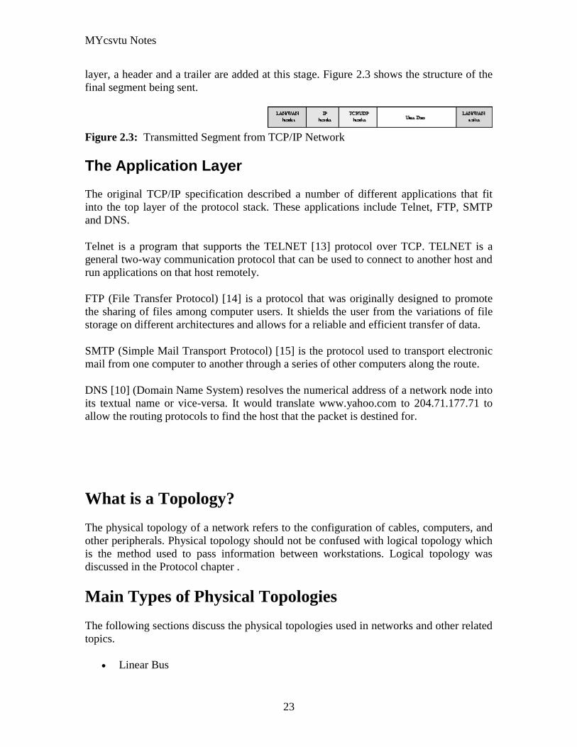
MYcsvtu Notes
23
layer a header and a trailer are added at this stage Figure 23 shows the structure of the
final segment being sent
Figure 23 Transmitted Segment from TCPIP Network
The Application Layer
The original TCPIP specification described a number of different applications that fit
into the top layer of the protocol stack These applications include Telnet FTP SMTP
and DNS
Telnet is a program that supports the TELNET [13] protocol over TCP TELNET is a
general two-way communication protocol that can be used to connect to another host and
run applications on that host remotely
FTP (File Transfer Protocol) [14] is a protocol that was originally designed to promote
the sharing of files among computer users It shields the user from the variations of file
storage on different architectures and allows for a reliable and efficient transfer of data
SMTP (Simple Mail Transport Protocol) [15] is the protocol used to transport electronic
mail from one computer to another through a series of other computers along the route
DNS [10] (Domain Name System) resolves the numerical address of a network node into
its textual name or vice-versa It would translate wwwyahoocom to 2047117771 to
allow the routing protocols to find the host that the packet is destined for
What is a Topology
The physical topology of a network refers to the configuration of cables computers and
other peripherals Physical topology should not be confused with logical topology which
is the method used to pass information between workstations Logical topology was
discussed in the Protocol chapter
Main Types of Physical Topologies
The following sections discuss the physical topologies used in networks and other related
topics
Linear Bus
MYcsvtu Notes
24
Star
Star-Wired Ring
Tree
Considerations When Choosing a Topology
Summary Chart
Linear Bus
A linear bus topology consists of a main run of cable with a terminator at each end (See
fig 1) All nodes (file server workstations and peripherals) are connected to the linear
cable Ethernet and LocalTalk networks use a linear bus topology
Fig 1 Linear Bus topology
Advantages of a Linear Bus Topology
Easy to connect a computer or peripheral to a linear bus
Requires less cable length than a star topology
Disadvantages of a Linear Bus Topology
Entire network shuts down if there is a break in the main cable
Terminators are required at both ends of the backbone cable
Difficult to identify the problem if the entire network shuts down
Not meant to be used as a stand-alone solution in a large building
Star
A star topology is designed with each node (file server workstations and peripherals)
connected directly to a central network hub or concentrator (See fig 2)
Data on a star network passes through the hub or concentrator before continuing to its
destination The hub or concentrator manages and controls all functions of the network It
also acts as a repeater for the data flow This configuration is common with twisted pair
cable however it can also be used with coaxial cable or fiber optic cable
MYcsvtu Notes
25
Fig 2 Star topology
Advantages of a Star Topology
Easy to install and wire
No disruptions to the network then connecting or removing devices
Easy to detect faults and to remove parts
Disadvantages of a Star Topology
Requires more cable length than a linear topology
If the hub or concentrator fails nodes attached are disabled
More expensive than linear bus topologies because of the cost of the
concentrators
The protocols used with star configurations are usually Ethernet or LocalTalk Token
Ring uses a similar topology called the star-wired ring
Star-Wired Ring
A star-wired ring topology may appear (externally) to be the same as a star topology
Internally the MAU (multistation access unit) of a star-wired ring contains wiring that
allows information to pass from one device to another in a circle or ring (See fig 3) The
Token Ring protocol uses a star-wired ring topology
Tree
A tree topology combines characteristics of linear bus and star topologies It consists of
groups of star-configured workstations connected to a linear bus backbone cable (See fig
MYcsvtu Notes
26
4) Tree topologies allow for the expansion of an existing network and enable schools to
configure a network to meet their needs
Fig 4 Tree topology
Advantages of a Tree Topology
Point-to-point wiring for individual segments
Supported by several hardware and software venders
Disadvantages of a Tree Topology
Overall length of each segment is limited by the type of cabling used
If the backbone line breaks the entire segment goes down
More difficult to configure and wire than other topologies
5-4-3 Rule
A consideration in setting up a tree topology using Ethernet protocol is the 5-4-3 rule
One aspect of the Ethernet protocol requires that a signal sent out on the network cable
reach every part of the network within a specified length of time Each concentrator or
repeater that a signal goes through adds a small amount of time This leads to the rule that
between any two nodes on the network there can only be a maximum of 5 segments
connected through 4 repeatersconcentrators In addition only 3 of the segments may be
populated (trunk) segments if they are made of coaxial cable A populated segment is one
which has one or more nodes attached to it In Figure 4 the 5-4-3 rule is adhered to The
MYcsvtu Notes
27
furthest two nodes on the network have 4 segments and 3 repeatersconcentrators
between them
This rule does not apply to other network protocols or Ethernet networks where all fiber
optic cabling or a combination of a fiber backbone with UTP cabling is used If there is a
combination of fiber optic backbone and UTP cabling the rule is simply translated to 7-
6-5 rule
] Mesh
Full
Fully Connected The type of network topology in which each of the nodes of the network is
connected to each of the other nodes in the network with a point-to-point link ndash
this makes it possible for data to be simultaneously transmitted from any single
node to all of the other nodes
Note The physical fully connected mesh topology is generally too costly and
complex for practical networks although the topology is used when there are only
a small number of nodes to be interconnected[3]
Partial
Partially Connected The type of network topology in which some of the nodes of the network are
connected to more than one other node in the network with a point-to-point link ndash
this makes it possible to take advantage of some of the redundancy that is
provided by a physical fully connected mesh topology without the expense and
complexity required for a connection between every node in the network
Note In most practical networks that are based upon the physical partially
connected mesh topology all of the data that is transmitted between nodes in the
network takes the shortest path between nodes except in the case of a failure or
break in one of the links in which case the data takes an alternate path to the
destination ndash this implies that the nodes of the network possess some type of
logical routing algorithm to determine the correct path to use at any particular
time
[edit] Hybrid Network Topologies
The hybrid topology is a type of network topology that is composed of one or more
interconnections of two or more networks that are based upon different physical
topologies or a type of network topology that is composed of one or more
interconnections of two or more networks that are based upon the same physical
topology but where the physical topology of the network resulting from such an
interconnection does not meet the definition of the original physical topology of the
interconnected networks (eg the physical topology of a network that would result from
an interconnection of two or more networks that are based upon the physical star
topology might create a hybrid topology which resembles a mixture of the physical star
MYcsvtu Notes
28
and physical bus topologies or a mixture of the physical star and the physical tree
topologies depending upon how the individual networks are interconnected while the
physical topology of a network that would result from an interconnection of two or more
networks that are based upon the physical distributed bus network retains the topology of
a physical distributed bus network)
Star-Bus A type of network topology in which the central nodes of one or more individual
networks that are based upon the physical star topology are connected together
using a common bus network whose physical topology is based upon the
physical linear bus topology the endpoints of the common bus being terminated
with the characteristic impedance of the transmission medium where required ndash
eg two or more hubs connected to a common backbone with drop cables
through the port on the hub that is provided for that purpose (eg a properly
configured uplink port) would comprise the physical bus portion of the physical
star-bus topology while each of the individual hubs combined with the
individual nodes which are connected to them would comprise the physical star
portion of the physical star-bus topology
Star-of-Stars
Hierarchical Star A type of network topology that is composed of an interconnection of individual
networks that are based upon the physical star topology connected together in a
hierarchical fashion to form a more complex network ndash eg a top level central
node which is the hub of the top level physical star topology and to which other
second level central nodes are attached as the spoke nodes each of which in
turn may also become the central nodes of a third level physical star topology
Notes 1) The physical hierarchical star topology is not a combination of the physical
linear bus and the physical star topologies as cited in some texts as there is no
common linear bus within the topology although the top level hub which is the
beginning of the physical hierarchical star topology may be connected to the
backbone of another network such as a common carrier which is topologically
not considered to be a part of the local network ndash if the top level central node is
connected to a backbone that is considered to be a part of the local network then
the resulting network topology would be considered to be a hybrid topology that
is a mixture of the topology of the backbone network and the physical hierarchical
star topology
2) The physical hierarchical star topology is also sometimes incorrectly referred
to as a physical tree topology since its physical topology is hierarchical however
the physical hierarchical star topology does not have a structure that is determined
by a branching factor as is the case with the physical tree topology and therefore
nodes may be added to or removed from any node that is the hub of one of the
individual physical star topology networks within a network that is based upon the
physical hierarchical star topology
3) The physical hierarchical star topology is commonly used in outside plant
(OSP) cabling to connect various buildings to a central connection facility which
MYcsvtu Notes
29
may also house the demarcation point for the connection to the data transmission
facilities of a common carrier and in inside plant (ISP) cabling to connect
multiple wiring closets within a building to a common wiring closet within the
same building which is also generally where the main backbone or trunk that
connects to a larger network if any enters the building
Star-wired Ring A type of hybrid physical network topology that is a combination of the physical
star topology and the physical ring topology the physical star portion of the
topology consisting of a network in which each of the nodes of which the network
is composed are connected to a central node with a point-to-point link in a hub
and spoke fashion the central node being the hub and the nodes that are
attached to the central node being the spokes (eg a collection of point-to-point
links from the peripheral nodes that converge at a central node) in a fashion that is
identical to the physical star topology while the physical ring portion of the
topology consists of circuitry within the central node which routes the signals on
the network to each of the connected nodes sequentially in a circular fashion
Note In an 8025 Token Ring network the central node is called a Multistation
Access Unit (MAU)
Hybrid Mesh A type of hybrid physical network topology that is a combination of the physical
partially connected topology and one or more other physical topologies the mesh
portion of the topology consisting of redundant or alternate connections between
some of the nodes in the network ndash the physical hybrid mesh topology is
commonly used in networks which require a high degree of availability
Considerations When Choosing a Topology
Money A linear bus network may be the least expensive way to install a network
you do not have to purchase concentrators
Length of cable needed The linear bus network uses shorter lengths of cable
Future growth With a star topology expanding a network is easily done by
adding another concentrator
Cable type The most common cable in schools is unshielded twisted pair which
is most often used with star topologies
Summary Chart
Common Cable Common Protocol
Linear Bus Twisted Pair
Coaxial
Ethernet
LocalTalk
MYcsvtu Notes
30
Fiber
Star Twisted Pair
Fiber
Ethernet
LocalTalk
Star-Wired Ring Twisted Pair Token Ring
Tree
Twisted Pair
Coaxial
Fiber
Ethernet
Internet vs Web
The Internet and the World Wide Web are not synonymous the Internet is a collection of
interconnected computer networks linked by copper wires fiber-optic cables wireless
connections etc the Web is a collection of interconnected documents and other
resources linked by hyperlinks and URLs The World Wide Web is accessible via the
Internet as are many other services including e-mail file sharing and others described
below
The best way to define and distinguish between these terms is to understand the Internet
protocol suite This collection of protocols is organized into layers such that each layer
provides the foundation and the services required by the layer above In this conception
the term Internet refers to computer networks that all communicate with IP (Internet
protocol) and TCP (transfer control protocol) Once this networking structure is
established then other protocols can run ―on top These other protocols are sometimes
called services or applications Hypertext transfer protocol or HTTP is an application
layer protocol that links billions of files together into the World Wide Web
Common uses of the Internet
The World Wide Web
Through keyword-driven Internet research using search engines like Google
millions worldwide have easy instant access to a vast and diverse amount of
online information Compared to encyclopedias and traditional libraries the
World Wide Web has enabled a sudden and extreme decentralization of
information and data
Many individuals and some companies and groups have adopted the use of Web logs or
blogs which are largely used as easily-updatable online diaries Some commercial
organizations encourage staff to fill them with advice on their areas of specialization in
the hope that visitors will be impressed by the expert knowledge and free information
and be attracted to the corporation as a result One example of this practice is Microsoft
MYcsvtu Notes
31
whose product developers publish their personal blogs in order to pique the publics
interest in their work
For more information on the distinction between the World Wide Web and the Internet
itself mdash as in everyday use the two are sometimes confused mdash see Dark internet where
this is discussed in more detail
Remote access
The Internet allows computer users to connect to other computers and information stores
easily wherever they may be across the world They may do this with or without the use
of security authentication and encryption technologies depending on the requirements
This is encouraging new ways of working from home collaboration and information
sharing in many industries An accountant sitting at home can audit the books of a
company based in another country on a server situated in a third country that is remotely
maintained by IT specialists in a fourth These accounts could have been created by
home-working book-keepers in other remote locations based on information e-mailed to
them from offices all over the world Some of these things were possible before the
widespread use of the Internet but the cost of private leased lines would have made
many of them infeasible in practice
An office worker away from his desk perhaps the other side of the world on a business
trip or a holiday can open a remote desktop session into his normal office PC using a
secure Virtual Private Network (VPN) connection via the Internet This gives him
complete access to all his normal files and data including e-mail and other applications
while he is away
This concept is also referred to by some network security people as the Virtual Private
Nightmare because it extends the secure perimeter of a corporate network into its
employees homes this has been the source of some notable security breaches but also
provides security for the workers
Functions
File-sharing
Instant messaging
Internet fax
Search engine
World Wide Web
MYcsvtu Notes
32
Intranets
What are Intranets
bull Intranet is Intra+ Net so an Intranet is an internal or private Internet used strictly
within the confines of a company university or organization Inter means
between or among hence the difference between the Internet and an Intranet
Some formal definitions of Intranets
bull Brown amp Duguid ―Intranets help present and
circulate boundary objects
bull Choo Detlor amp Turnbull ―Intranetshellip support the creation sharing and use of
knowledge
bull Stenmark ―Intranets are organizationally
restricted
A technical definition
bull An Intranet is a network based on the internet TCPIP open standard An intranet
belongs to an organization and is designed to be accessible only by the
organizations members employees or others with authorization An intranets
Web site looks and act just like other Web sites but has a firewall surrounding it
to fend off unauthorized users
Design Of Intranets
Steps
bull Analyze the organizationlsquos information ecology
bull Identify the typical problems experienced by users
bull Analyze the information behaviors of these set of users
bull Create value added processes to resolve the problems of users and to improve the
Information Ecology
Value Added Processes
bull Intranets may be designed to improve the organizational information ecology
MYcsvtu Notes
33
bull Intranets provide a unified information space in which users can communicate
and collaborate with others
bull intranet applications and services may add value by supporting the organizationlsquos
knowledge creating and decision making process
Two Models of Online Environments
Centralized
Distributed
Centralized Environments
bull Before the web the centralized model was all we had (examples include
CompuServe Prodigy)
bull On the web centralized models include site-based services such as Yahoo
bull Most (all) college and university services are offered using the centralized
model
MYcsvtu Notes
34
bull But centralized environments are static inflexible expensive
Distributed Environments
bull The World Wide Web is an example of a distributed environment
bull Resources access are not centralized but scattered around the world
ndash Resources in the form of a network of connected (via DNS) web servers
ndash Access in the form of a network of connected (via DNS) internet service
providers
ndash Users in the form of individualized and connected (via HTTP) web
browsers
bull The big issue ndash integration ndash that is making different systems work together
Design Principles
Network Design Principles
ndash Specifies how networks differ from traditional learning
ndash The idea is that each principle confers an advantage over non-network
systems
ndash Can be used as a means of evaluating new technology
1 Decentralize
ndash Centralized networks have a characteristic starlsquo shape
bull Some entities have many connections
bull The vast majority have few
bull Eg broadcast network teacher in a classroom
ndash Decentralized networks form a mesh
bull The weight of connections flow is distributed
bull Balanced load = more stable
bull Foster connections between entities fill outlsquo the star
Distribute
ndash Network entities reside in different physical locations
bull Reduces risk of network failure
bull Reduces need for major infrastructure such as powerful servers
large bandwidth massive storage
ndash Examples
bull Peer-to-peer networks such as Kazaa Gnutella
bull Content syndication networks such as RSS
ndash Emphasis is on sharing not copying
bull Locallsquo copies are temporary
MYcsvtu Notes
35
Computer Graphics
Computer Graphics is about animation (films)
Games are very important in Computer Graphics
Medical Imaging is another driving force
Computer Aided Design too
Graphics Definitions
bull Point
ndash a location in space 2D or 3D
ndash sometimes denotes one pixel
bull Line
ndash straight path connecting two points
ndash infinitesimal width consistent density
ndash beginning and end on points
bull Vertex
ndash point in 3D
bull Edge
ndash line in 3D connecting two vertices
bull PolygonFaceFacet
ndash arbitrary shape formed by connected vertices
ndash fundamental unit of 3D computer graphics
bull Raster
ndash derived from TV systems for a row of pixels
ndash commonly referred to as a scanline
ndash does influence algorithms ndash reducing memory requirements parallelism
etc
ndash is the derivation of rasterization scan-line algorithms
Displays
bull Most desktop displays use a cathode ray tube (CRT) while portable computing
devices such as laptops incorporate liquid crystal display (LCD)
bull Because of their slimmer design and smaller energy consumption monitors using
LCD technologies are beginning to replace the venerable CRT on many desktops
Cathode-Ray Tubes
MYcsvtu Notes
36
bull Classical output device is a monitor
bull Cathode-Ray Tube (CRT)
ndash Invented by Karl Ferdinand Braun (1897)
ndash Beam of electrons directed from cathode (-)to phosphor-coated
(fluorescent) screen (anode (+))
ndash Directed by magnetic focusing and deflection coils (anodes) in vacuum
filled tube
ndash Phosphor emits photon of light when hit by an electron of varied
persistence (long 15-20 ms for texts short lt 1ms for animation)
ndash Refresh rate (50-60 Hz 72-76 Hz) to avoid flicker trail
ndash Phosphors are organic compounds characterized by their persistence and
their color (blue red green)
Cathode-Ray Tubes
bull Cathode-Ray Tube (CRT)
ndash Horizontal deflection and vertical deflection direct the electron beam to
any point on the screen
ndash Intensity knob regulates the flow of electrons by controlling the voltage at
the control grid (high voltage reduces the electron density and thus
brightness)
ndash Accelerating voltage from positive coating inside screen (anode screen) or
an accelerating anode
bull Image maintenance
ndash Charge distribution to store picture information
OR
ndash Refresh CRT refreshes the display constantly to maintain phosphor glow
Cathode-Ray Tubes
bullCathode-Ray Tube (CRT)
ndash Horizontal deflection and vertical deflection direct the electron beam to any point
on the screen
ndash Intensity knob regulates the flow of electrons by controlling the voltage at the
control grid (high voltage reduces the electron density and thus brightness)
ndash Accelerating voltage from positive coating inside screen (anode screen) or an
accelerating anode
bullImage maintenance
ndash Charge distribution to store picture information
OR
ndash Refresh CRT refreshes the display constantly to maintain phosphor glow
bull Characteristics of Cathode-Ray Tube (CRT)
MYcsvtu Notes
37
ndash Intensity is proportional to the number of electrons repelled in beam per
second (brightness)
ndash Resolution is the maximum number of points that can be displayed
without overlap is expressed as number of horizontal points by number of
vertical points points are called pixels (picture elements) example
resolution 1024 x 768 pixels Typical resolution is 1280 x 1024 pixels
bull High-definition systems high resolution systems
bull Focusing
ndash Focusing forces the electron beam to converge to a point on the monitor
screen
ndash Can be electrostatic (lens) or magnetic (field)
bull Deflection
ndash Deflection directs the electron beam horizontally andor vertically to any
point on the screen
ndash Can be controlled by electric (deflection plates slide 9) or magnetic fields
(deflection coils slide 5)
ndash Magnetic coils two pairs (topbottom leftright) of tube neck
ndash Electric plates two pairs (horizontal vertical)
Raster-scan Displays
bullVideo displays can be either raster-scan or random-scan displays
bullRaster-scan display is the most common type of monitor using a CRT
bullThe electron beam scans the screen from top to bottom one row at a time Each row is
called a scan line
bullThe electron beam is turned on and off to produce a collection of dots painted one row at
a time These will form the image
bullA raster is a matrix of pixels covering the screen area and is composed of raster lines
Raster-scan Displays
MYcsvtu Notes
38
Raster-scan Displays
bullThe image is stored in a frame buffer containing the total screen area and where each
memory location corresponds to a pixel
bullIn a monochrome system each bit is 1 or 0 for the corresponding pixel to be on or off
(bitmap)
bullThe display processor scans the frame buffer to turn electron beam onoff depending if
the bit is 1 or 0
bullFor color monitors the frame buffer also contains the color of each pixel (color buffer)
as well as other characteristics of the image (gray scale hellip) 8 bitspixel 0255
(pixmap)
bullDepth of the buffer area is the number of bits per pixel (bit planes) up to 24
bullExamples television panels printers PC monitors (99 of raster-scan)
Raster-scan Displays
bullRefresh rate 24 is a minimum to avoid flicker corresponding to 24 Hz (1 Hz = 1 refresh
per second)
bullCurrent raster-scan displays have a refresh rate of at least 60 frames (60 Hz) per second
up to 120 (120 Hz)
bullUses large memory 640x480 307200 bits 38 kB
bullRefresh procedure
MYcsvtu Notes
39
ndashHorizontal retrace ndash beam returns to left of screen
ndashVertical retrace ndash bean returns to top left corner of screen
ndashInterlaced refresh ndash display first even-numbered lines then odd-numbered lines
permits to see the image in half the time
useful for slow refresh rates (30 Hz shows as 60 Hz)
Random-scan Displays
bullRandom scan systems are also called vector stroke-writing or calligraphic displays
bullThe electron beam directly draws the picture in any specified order
bullA pen plotter is an example of such a system
bullPicture is stored in a display list refresh display file vector file or display program as a
set of line drawing commands
bullRefreshes by scanning the list 30 to 60 times per second
bullMore suited for line-drawing applications such as architecture and manufacturing
Random-scan Displays
bullAdvantages
ndashHigh resolution
ndashEasy animation
ndashRequires little memory
bullDisadvantages
ndashRequires intelligent electron beam (processor controlled)
ndashLimited screen density limited to simple line-based images
ndashLimited color capability
bullImproved in the 1960lsquos by the Direct View Storage Tube (DVST) from Tektronix
Color CRT Monitor
Uses different phosphors a combination of Red Green and Blue to produce any color
Two methods
Random scan uses beam penetration
2 layers (Red Green) phosphors low speed electrons excite Red high speed electrons
excite Green interrmediate speed excite both to get yellow and orange Color is
controlled by electron beam voltage
Only produces a restricted set of colors
Raster scan uses a shadow mask with three electron guns Red Green and Blue (RGB
color model) Color is produced by adjusting the intensity level of each electron beam
Produces a wide range of colors from 8 to several millions
Raster scan
Most common as found in televisions
Beam scanned left to right flicked back to rescan from top to bottom then repeated
Repeated at 30Hz per frame sometimes higher to reduce flicker Interlacing scanning
MYcsvtu Notes
40
odd lines in whole screen then even lines is also used to reduce flicker Can also use
high-persistence phosphor to reduce flicker but causes image smearing especially with
significant animation
Resolution typically 512x512 but high-quality screens are available (and becoming more
common) at up to approximately 1600x1200 pixels Sun workstations have screens of
1192x980 pixels
Black amp white screens can display grayscale by varying the intensity of the electron
beam
Colour is achieved using three electron guns which hit red green or blue phosphors
Combining these colours can produce many others including white (all on) Phosphor
dots focused using a shadow mask - makes colour screens lower resolution than
monochrome
Alternative approach beam penetration Special phosphor glows a different colour
depending on intensity of beam
Colour or intensity at pixel held by computerlsquos video card 1 bitpixel can store offon
information hence only black ampwhite More bitspixel give rise to more colour
possibilities eg 8 bitspixel gives rise to 2^8=256 possible colours at any one time
Random Scan (Directed-beam refresh vector display)
Instead of scanning the whole display sequentially and horizontally the random scan
draws the lines to be displayed directly Screen update at gt30Hz to reduce flicker
Jaggies not found and higher resolutions possible (up to 4096x4096 pixels) Colour
achieved using beam penetration generally of poorer quality Eye strain and fatigue still
a problem and vector displays are more expensive
Direct view storage tube (DVST)
Used a lot in analogue storage oscilloscopes
Similar to random scan crt but image maintained by flood guns - no flicker Can be
incrementally updated but not selectively erased image has to be redrawn on completely
erased screen High resolution (typically 4096x3120 pixels) but low contrast low
brightness and difficulty in displaying colour
What is a Multimedia System
bull A system that involves
ndash generation
ndash representation
ndash storage
ndash transmission
ndash search and retrieval
ndash delivery
MYcsvtu Notes
41
of multimedia information
productionauthoring tools
compression and formats
file system design
networking issues
database management
server design streaming
Multimedia System Architecture
Information management subsystem Presentation Query
Storage subsystem Efficiently stored
amp retrieved
Network subsystem Delivery
Adaptation in Multimedia Systems
bull Multimedia systems can profit a lot from personalization
ndash User behavior
ndash User properties
bull Adaptation
ndash Models
ndash Mechanisms
Multimedia in a mobile environment
MYcsvtu Notes
42
bull Applications
ndash Emergency response systems mobile commerce phone service
entertainment games
What is Sound
A ripple is a pressure wave in water created by an object striking the water
Sound is a pressure wave in air created for example by an object such as a string
or our vocal cords vibrating Dark here represents more pressure light represents
less
MYcsvtu Notes
43
Sine Waves Form Pure Tones
This simple sound wave is a Sine Wave a Pure tone produced by a simple vibration
Sine Wave Sample Tone
This can be represented graphically as shown above
Converting Pressure into Voltage
The pressure wave of sound moves a diaphragm in the microphone which produces a
voltage proportional to the pressure of the sound wave at each instant
Animation
MYcsvtu Notes
44
bull Animation is the rapid display of a sequence of images of 2-D artwork or model
positions in order to create an illusion of movement It is an optical illusion of
motion due to the phenomenon of persistence of vision This could be anything
from a flip book to a motion picture film Animation deals with the generation
sequencing and display a set of images which is called frames to create an effect
of visual change or motion similar to a movie film
bull Animation is used in those instance where videography is not possible
Hardware Requirement For Animation
bull Image Generation Tools amp Devices
bull Computer monitors with image display Capability
Software Requirement For Animation
bull Animation creating software
bull Screen Capture Software
bull Animation Clips
bull Software support For High Resolution
bull Recording amp Playback Capability
bull Transition effect
Early animation
There is no single person that can be considered the creator of the art of animation as
there were several people doing several projects which could be considered various types
of animation all around the same time (Short hand-drawn animation scenes could be
presented with the Phenakistoscope the Zoetrope and other optical toys already in the
early 1800s)
The following is a brief listing on those who are often acknowledged as significant to the
development of animation Note that this list is by no means a comprehensive list of
contributors to early animation
Georges Meacuteliegraves was a creator of special effect films such as A Trip to the Moon He
used many techniques ndash one of which was to stop the camera rolling change something
in the scene and then continue rolling the film This is a very similar idea to that of stop-
motion animation Meacuteliegraves accidentally happened upon the technique when his camera
broke down while shooting a bus driving by When the camera was fixed a horse
happened to be passing by just as Meacuteliegraves continued to film The result was that the bus
appeared to change into a horse
MYcsvtu Notes
45
Fantasmagorie by Emile Cohl 1908
Eacutemile Cohl began drawing cartoon strips and created a film in 1908 called
Fantasmagorie The film largely consisted of a stick figure moving about and
encountering all manner of morphing objects such as a wine bottle that transforms into a
flower There were also sections of live action where the animatorlsquos hands would enter
the scene The film was created by drawing each frame on paper and then shooting each
frame onto negative film which gave the picture a blackboard look
Winsor McCay created detailed animations that required a team of artists and painstaking
attention for detail Each frame was drawn on paper requiring backgrounds to be
redrawn as well characters to be animated His films such as Gertie the Dinosaur (1914)
and The Sinking of the Lusitania (1918) were of an impressive scale although The
Sinking of the Lusitania used cels
In 1919 Otto Messmer created the character of Felix the cat for Pat Sullivans animation
studios The importance of Felix lies in the characters strong personality created largely
through gesture and actions
Animation techniques
Animation techniques are incredibly varied and difficult to categorize Techniques are
often related or combined The following is a brief on common types of animation
Again this list is by no means comprehensive
Traditional animation
An example of traditional animation a horse animated by rotoscoping from Edweard
Muybridges 19th century photos
Main article Traditional animation
MYcsvtu Notes
46
Also called cel animation the frames of a traditionally animated movie are hand-drawn
The drawings are traced or copied onto transparent acetate sheets called cels which are
then placed over a painted background and photographed one by one on a rostrum
camera Nowadays the use of cels (and cameras) is mostly obsolete since the drawings
are scanned into computers and digitally transferred directly to 35 mm film The look
of traditional cel animation is still preserved and the character animators work has
remained essentially the same over the past 70 years Because of the digital influence
over modern cel animation it is also known as tradigital animation
Examples The Lion King Spirited Away Les Triplettes de Belleville
Full animation The most common style in animation known for its realistic and often very detailed art
Examples All Disney feature length animated films The Secret of NIMH The Iron Giant
Limited animation A cheaper process of making animated cartoons that does not follow a realistic
approach
Examples The Flintstones Yellow Submarine
Rubber hose The characters are usually cartoony and the animators have a lot of artistic freedom as
rubber hose animations dont have to follow the laws of physics and anatomy in the same
degree as the other main styles in animation
Examples Early Mickey Mouse cartoons Ren and Stimpy Popeye
Rotoscoping A technique where animators trace live action movement frame by frame for use in
animated films
Examples Gullivers Travels American Pop
Stop motion
Stop-motion animation is any type of animation which requires the animator to physically
alter the scene shoot a frame again alter the scene and shoot a frame and so on to create
the animation There are many different types of stop-motion animation some noteable
examples are listed below
Clay animation
MYcsvtu Notes
47
A clay animation scene from a TV commercial
Often abbreviated to claymation this is a type of stop-motion animation using
figures made of clay or a similar malleable material The figures may have an
armature or wire frame inside of them similar to puppet animation (below)
Alternatively the figures may be made entirely of clay such as in the films of
Bruce Bickford where clay creatures morph into a variety of different shapes
Examples Wallace and Gromit Dimensions of Dialogue by Jan Švankmajer The
Amazing Mr Bickford The Trap Door
Cutout animation In this type of stop-motion animation the animation is formed by moving 2-
dimensional pieces of material such as paper or cloth
Examples the animated sequences of Monty Pythons Flying Circus (often
referred to as Dada animation named after the Dada art movement[citation needed]
)
Tale of Tales early episodes of South Park
Silhouette animation A type of cutout animation where the viewer only sees black silhouettes
Example The Adventures of Prince Achmed the worlds oldest surviving
animated feature film from 1926
Graphic animation
Model animation In this form of animation model animated characters interact with and are a part
of the live-action world
Examples The films of Ray Harryhausen (Jason and the Argonauts) and Willis
OBrien (King Kong)
Go motion
Object animation
Pixilation Examples Neighbours
Puppet animation Puppet animation typically involves puppet figures interacting with each other in
a constructed environment in contrast to the real-world interaction in model
MYcsvtu Notes
48
animation (above) The puppets generally have an armature inside of them to
keep them still and steady as well as constraining them to move at particular
joints
Examples The Nightmare Before Christmas Robot Chicken The Tale of the Fox
Brickfilm
Puppetoon
Computer animation
A short gif animation
Like stop motion computer animation encompasses a variety of techniques the unifying
idea being that the animation is created digitally on a computer
2D animation Figures are created andor edited on the computer using 2D bitmap graphics or
created and edited using 2D vector graphics This includes automated
computerized versions of traditional animation techniques such as of tweening
morphing onion skinning and interpolated rotoscoping
Examples A Scanner Darkly Jib Jab
Analog computer animation
Flash animation
PowerPoint animation
A completely synthetic computer-generated scene
3D animation
MYcsvtu Notes
49
Figures are created in the computer using polygons To allow these meshes to
move they are given a digital armature (sculpture) This process is called rigging
Various other techniques can be applied such as mathematical functions
(gravity) simulated fur or hair effects such as fire and water and the use of
motion capture to name but a few
Examples The Incredibles Shrek
Cel-shaded animation
Morph target animation
Skeletal animation
Motion capture
Crowd simulation
Less common techniques
Drawn on film animation A technique where footage is produced by creating the
images directly on film stock
Paint-on-glass animationA technique for making animated films by manipulating slow-
drying oil paints on sheets of glass
Pinscreen animation Makes use of a screen filled with movable pins which can be
moved in or out by pressing an object onto the screen The screen is lit from the side so
that the pins cast shadows The technique has been used to create animated films with a
range of textural effects difficult to achieve with traditional cel animation
Sand animation Sand is moved around on a backlighted or frontlighted piece of glass to
create each frame for an animated film
Multimedia
Multimedia (Lat Multum + Medium) is media that uses multiple forms of information
content and information processing (eg text audio graphics animation video
interactivity) to inform or entertain the (user) audience Multimedia also refers to the use
of (but not limited to) electronic media to store and experience multimedia content
Multimedia is similar to traditional mixed media in fine art but with a broader scope The
term rich media is synonymous for interactive multimedia
Categorization
Multimedia may be broadly divided into linear and non-linear categories Linear active
content progresses without any navigation control for the viewer such as a cinema
presentation Non-linear content offers user interactivity to control progress as used with
MYcsvtu Notes
50
a computer game or used in self-paced computer based training Non-linear content is
also known as hypermedia content
Multimedia presentations can be live or recorded A recorded presentation may allow
interactivity via a navigation system A live multimedia presentation may allow
interactivity via interaction with the presenter or performer
There are 2 basic way to represent some information
Unimedium Presentation
Multimedia Presentation
In case of computer system the commonly used medioa for the purpose of storage
access and transmission of information are
bull Text
bull Graphics
bull Animation
bull Audio
bull Video
Multimedia Computer System require
bull Faster CPU
bull Larger Storage Devices
bull Larger Main Memory
bull Good Graphics Terminal
bull IO devices required to play an audio associated with the program
Transmission Mode
bull Asynchronous
bull Synchronous
bull Isochronous
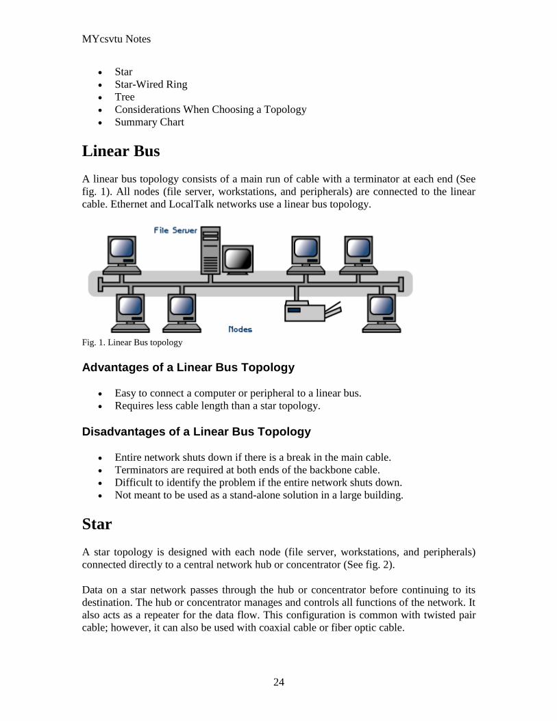
MYcsvtu Notes
24
Star
Star-Wired Ring
Tree
Considerations When Choosing a Topology
Summary Chart
Linear Bus
A linear bus topology consists of a main run of cable with a terminator at each end (See
fig 1) All nodes (file server workstations and peripherals) are connected to the linear
cable Ethernet and LocalTalk networks use a linear bus topology
Fig 1 Linear Bus topology
Advantages of a Linear Bus Topology
Easy to connect a computer or peripheral to a linear bus
Requires less cable length than a star topology
Disadvantages of a Linear Bus Topology
Entire network shuts down if there is a break in the main cable
Terminators are required at both ends of the backbone cable
Difficult to identify the problem if the entire network shuts down
Not meant to be used as a stand-alone solution in a large building
Star
A star topology is designed with each node (file server workstations and peripherals)
connected directly to a central network hub or concentrator (See fig 2)
Data on a star network passes through the hub or concentrator before continuing to its
destination The hub or concentrator manages and controls all functions of the network It
also acts as a repeater for the data flow This configuration is common with twisted pair
cable however it can also be used with coaxial cable or fiber optic cable
MYcsvtu Notes
25
Fig 2 Star topology
Advantages of a Star Topology
Easy to install and wire
No disruptions to the network then connecting or removing devices
Easy to detect faults and to remove parts
Disadvantages of a Star Topology
Requires more cable length than a linear topology
If the hub or concentrator fails nodes attached are disabled
More expensive than linear bus topologies because of the cost of the
concentrators
The protocols used with star configurations are usually Ethernet or LocalTalk Token
Ring uses a similar topology called the star-wired ring
Star-Wired Ring
A star-wired ring topology may appear (externally) to be the same as a star topology
Internally the MAU (multistation access unit) of a star-wired ring contains wiring that
allows information to pass from one device to another in a circle or ring (See fig 3) The
Token Ring protocol uses a star-wired ring topology
Tree
A tree topology combines characteristics of linear bus and star topologies It consists of
groups of star-configured workstations connected to a linear bus backbone cable (See fig
MYcsvtu Notes
26
4) Tree topologies allow for the expansion of an existing network and enable schools to
configure a network to meet their needs
Fig 4 Tree topology
Advantages of a Tree Topology
Point-to-point wiring for individual segments
Supported by several hardware and software venders
Disadvantages of a Tree Topology
Overall length of each segment is limited by the type of cabling used
If the backbone line breaks the entire segment goes down
More difficult to configure and wire than other topologies
5-4-3 Rule
A consideration in setting up a tree topology using Ethernet protocol is the 5-4-3 rule
One aspect of the Ethernet protocol requires that a signal sent out on the network cable
reach every part of the network within a specified length of time Each concentrator or
repeater that a signal goes through adds a small amount of time This leads to the rule that
between any two nodes on the network there can only be a maximum of 5 segments
connected through 4 repeatersconcentrators In addition only 3 of the segments may be
populated (trunk) segments if they are made of coaxial cable A populated segment is one
which has one or more nodes attached to it In Figure 4 the 5-4-3 rule is adhered to The
MYcsvtu Notes
27
furthest two nodes on the network have 4 segments and 3 repeatersconcentrators
between them
This rule does not apply to other network protocols or Ethernet networks where all fiber
optic cabling or a combination of a fiber backbone with UTP cabling is used If there is a
combination of fiber optic backbone and UTP cabling the rule is simply translated to 7-
6-5 rule
] Mesh
Full
Fully Connected The type of network topology in which each of the nodes of the network is
connected to each of the other nodes in the network with a point-to-point link ndash
this makes it possible for data to be simultaneously transmitted from any single
node to all of the other nodes
Note The physical fully connected mesh topology is generally too costly and
complex for practical networks although the topology is used when there are only
a small number of nodes to be interconnected[3]
Partial
Partially Connected The type of network topology in which some of the nodes of the network are
connected to more than one other node in the network with a point-to-point link ndash
this makes it possible to take advantage of some of the redundancy that is
provided by a physical fully connected mesh topology without the expense and
complexity required for a connection between every node in the network
Note In most practical networks that are based upon the physical partially
connected mesh topology all of the data that is transmitted between nodes in the
network takes the shortest path between nodes except in the case of a failure or
break in one of the links in which case the data takes an alternate path to the
destination ndash this implies that the nodes of the network possess some type of
logical routing algorithm to determine the correct path to use at any particular
time
[edit] Hybrid Network Topologies
The hybrid topology is a type of network topology that is composed of one or more
interconnections of two or more networks that are based upon different physical
topologies or a type of network topology that is composed of one or more
interconnections of two or more networks that are based upon the same physical
topology but where the physical topology of the network resulting from such an
interconnection does not meet the definition of the original physical topology of the
interconnected networks (eg the physical topology of a network that would result from
an interconnection of two or more networks that are based upon the physical star
topology might create a hybrid topology which resembles a mixture of the physical star
MYcsvtu Notes
28
and physical bus topologies or a mixture of the physical star and the physical tree
topologies depending upon how the individual networks are interconnected while the
physical topology of a network that would result from an interconnection of two or more
networks that are based upon the physical distributed bus network retains the topology of
a physical distributed bus network)
Star-Bus A type of network topology in which the central nodes of one or more individual
networks that are based upon the physical star topology are connected together
using a common bus network whose physical topology is based upon the
physical linear bus topology the endpoints of the common bus being terminated
with the characteristic impedance of the transmission medium where required ndash
eg two or more hubs connected to a common backbone with drop cables
through the port on the hub that is provided for that purpose (eg a properly
configured uplink port) would comprise the physical bus portion of the physical
star-bus topology while each of the individual hubs combined with the
individual nodes which are connected to them would comprise the physical star
portion of the physical star-bus topology
Star-of-Stars
Hierarchical Star A type of network topology that is composed of an interconnection of individual
networks that are based upon the physical star topology connected together in a
hierarchical fashion to form a more complex network ndash eg a top level central
node which is the hub of the top level physical star topology and to which other
second level central nodes are attached as the spoke nodes each of which in
turn may also become the central nodes of a third level physical star topology
Notes 1) The physical hierarchical star topology is not a combination of the physical
linear bus and the physical star topologies as cited in some texts as there is no
common linear bus within the topology although the top level hub which is the
beginning of the physical hierarchical star topology may be connected to the
backbone of another network such as a common carrier which is topologically
not considered to be a part of the local network ndash if the top level central node is
connected to a backbone that is considered to be a part of the local network then
the resulting network topology would be considered to be a hybrid topology that
is a mixture of the topology of the backbone network and the physical hierarchical
star topology
2) The physical hierarchical star topology is also sometimes incorrectly referred
to as a physical tree topology since its physical topology is hierarchical however
the physical hierarchical star topology does not have a structure that is determined
by a branching factor as is the case with the physical tree topology and therefore
nodes may be added to or removed from any node that is the hub of one of the
individual physical star topology networks within a network that is based upon the
physical hierarchical star topology
3) The physical hierarchical star topology is commonly used in outside plant
(OSP) cabling to connect various buildings to a central connection facility which
MYcsvtu Notes
29
may also house the demarcation point for the connection to the data transmission
facilities of a common carrier and in inside plant (ISP) cabling to connect
multiple wiring closets within a building to a common wiring closet within the
same building which is also generally where the main backbone or trunk that
connects to a larger network if any enters the building
Star-wired Ring A type of hybrid physical network topology that is a combination of the physical
star topology and the physical ring topology the physical star portion of the
topology consisting of a network in which each of the nodes of which the network
is composed are connected to a central node with a point-to-point link in a hub
and spoke fashion the central node being the hub and the nodes that are
attached to the central node being the spokes (eg a collection of point-to-point
links from the peripheral nodes that converge at a central node) in a fashion that is
identical to the physical star topology while the physical ring portion of the
topology consists of circuitry within the central node which routes the signals on
the network to each of the connected nodes sequentially in a circular fashion
Note In an 8025 Token Ring network the central node is called a Multistation
Access Unit (MAU)
Hybrid Mesh A type of hybrid physical network topology that is a combination of the physical
partially connected topology and one or more other physical topologies the mesh
portion of the topology consisting of redundant or alternate connections between
some of the nodes in the network ndash the physical hybrid mesh topology is
commonly used in networks which require a high degree of availability
Considerations When Choosing a Topology
Money A linear bus network may be the least expensive way to install a network
you do not have to purchase concentrators
Length of cable needed The linear bus network uses shorter lengths of cable
Future growth With a star topology expanding a network is easily done by
adding another concentrator
Cable type The most common cable in schools is unshielded twisted pair which
is most often used with star topologies
Summary Chart
Common Cable Common Protocol
Linear Bus Twisted Pair
Coaxial
Ethernet
LocalTalk
MYcsvtu Notes
30
Fiber
Star Twisted Pair
Fiber
Ethernet
LocalTalk
Star-Wired Ring Twisted Pair Token Ring
Tree
Twisted Pair
Coaxial
Fiber
Ethernet
Internet vs Web
The Internet and the World Wide Web are not synonymous the Internet is a collection of
interconnected computer networks linked by copper wires fiber-optic cables wireless
connections etc the Web is a collection of interconnected documents and other
resources linked by hyperlinks and URLs The World Wide Web is accessible via the
Internet as are many other services including e-mail file sharing and others described
below
The best way to define and distinguish between these terms is to understand the Internet
protocol suite This collection of protocols is organized into layers such that each layer
provides the foundation and the services required by the layer above In this conception
the term Internet refers to computer networks that all communicate with IP (Internet
protocol) and TCP (transfer control protocol) Once this networking structure is
established then other protocols can run ―on top These other protocols are sometimes
called services or applications Hypertext transfer protocol or HTTP is an application
layer protocol that links billions of files together into the World Wide Web
Common uses of the Internet
The World Wide Web
Through keyword-driven Internet research using search engines like Google
millions worldwide have easy instant access to a vast and diverse amount of
online information Compared to encyclopedias and traditional libraries the
World Wide Web has enabled a sudden and extreme decentralization of
information and data
Many individuals and some companies and groups have adopted the use of Web logs or
blogs which are largely used as easily-updatable online diaries Some commercial
organizations encourage staff to fill them with advice on their areas of specialization in
the hope that visitors will be impressed by the expert knowledge and free information
and be attracted to the corporation as a result One example of this practice is Microsoft
MYcsvtu Notes
31
whose product developers publish their personal blogs in order to pique the publics
interest in their work
For more information on the distinction between the World Wide Web and the Internet
itself mdash as in everyday use the two are sometimes confused mdash see Dark internet where
this is discussed in more detail
Remote access
The Internet allows computer users to connect to other computers and information stores
easily wherever they may be across the world They may do this with or without the use
of security authentication and encryption technologies depending on the requirements
This is encouraging new ways of working from home collaboration and information
sharing in many industries An accountant sitting at home can audit the books of a
company based in another country on a server situated in a third country that is remotely
maintained by IT specialists in a fourth These accounts could have been created by
home-working book-keepers in other remote locations based on information e-mailed to
them from offices all over the world Some of these things were possible before the
widespread use of the Internet but the cost of private leased lines would have made
many of them infeasible in practice
An office worker away from his desk perhaps the other side of the world on a business
trip or a holiday can open a remote desktop session into his normal office PC using a
secure Virtual Private Network (VPN) connection via the Internet This gives him
complete access to all his normal files and data including e-mail and other applications
while he is away
This concept is also referred to by some network security people as the Virtual Private
Nightmare because it extends the secure perimeter of a corporate network into its
employees homes this has been the source of some notable security breaches but also
provides security for the workers
Functions
File-sharing
Instant messaging
Internet fax
Search engine
World Wide Web
MYcsvtu Notes
32
Intranets
What are Intranets
bull Intranet is Intra+ Net so an Intranet is an internal or private Internet used strictly
within the confines of a company university or organization Inter means
between or among hence the difference between the Internet and an Intranet
Some formal definitions of Intranets
bull Brown amp Duguid ―Intranets help present and
circulate boundary objects
bull Choo Detlor amp Turnbull ―Intranetshellip support the creation sharing and use of
knowledge
bull Stenmark ―Intranets are organizationally
restricted
A technical definition
bull An Intranet is a network based on the internet TCPIP open standard An intranet
belongs to an organization and is designed to be accessible only by the
organizations members employees or others with authorization An intranets
Web site looks and act just like other Web sites but has a firewall surrounding it
to fend off unauthorized users
Design Of Intranets
Steps
bull Analyze the organizationlsquos information ecology
bull Identify the typical problems experienced by users
bull Analyze the information behaviors of these set of users
bull Create value added processes to resolve the problems of users and to improve the
Information Ecology
Value Added Processes
bull Intranets may be designed to improve the organizational information ecology
MYcsvtu Notes
33
bull Intranets provide a unified information space in which users can communicate
and collaborate with others
bull intranet applications and services may add value by supporting the organizationlsquos
knowledge creating and decision making process
Two Models of Online Environments
Centralized
Distributed
Centralized Environments
bull Before the web the centralized model was all we had (examples include
CompuServe Prodigy)
bull On the web centralized models include site-based services such as Yahoo
bull Most (all) college and university services are offered using the centralized
model
MYcsvtu Notes
34
bull But centralized environments are static inflexible expensive
Distributed Environments
bull The World Wide Web is an example of a distributed environment
bull Resources access are not centralized but scattered around the world
ndash Resources in the form of a network of connected (via DNS) web servers
ndash Access in the form of a network of connected (via DNS) internet service
providers
ndash Users in the form of individualized and connected (via HTTP) web
browsers
bull The big issue ndash integration ndash that is making different systems work together
Design Principles
Network Design Principles
ndash Specifies how networks differ from traditional learning
ndash The idea is that each principle confers an advantage over non-network
systems
ndash Can be used as a means of evaluating new technology
1 Decentralize
ndash Centralized networks have a characteristic starlsquo shape
bull Some entities have many connections
bull The vast majority have few
bull Eg broadcast network teacher in a classroom
ndash Decentralized networks form a mesh
bull The weight of connections flow is distributed
bull Balanced load = more stable
bull Foster connections between entities fill outlsquo the star
Distribute
ndash Network entities reside in different physical locations
bull Reduces risk of network failure
bull Reduces need for major infrastructure such as powerful servers
large bandwidth massive storage
ndash Examples
bull Peer-to-peer networks such as Kazaa Gnutella
bull Content syndication networks such as RSS
ndash Emphasis is on sharing not copying
bull Locallsquo copies are temporary
MYcsvtu Notes
35
Computer Graphics
Computer Graphics is about animation (films)
Games are very important in Computer Graphics
Medical Imaging is another driving force
Computer Aided Design too
Graphics Definitions
bull Point
ndash a location in space 2D or 3D
ndash sometimes denotes one pixel
bull Line
ndash straight path connecting two points
ndash infinitesimal width consistent density
ndash beginning and end on points
bull Vertex
ndash point in 3D
bull Edge
ndash line in 3D connecting two vertices
bull PolygonFaceFacet
ndash arbitrary shape formed by connected vertices
ndash fundamental unit of 3D computer graphics
bull Raster
ndash derived from TV systems for a row of pixels
ndash commonly referred to as a scanline
ndash does influence algorithms ndash reducing memory requirements parallelism
etc
ndash is the derivation of rasterization scan-line algorithms
Displays
bull Most desktop displays use a cathode ray tube (CRT) while portable computing
devices such as laptops incorporate liquid crystal display (LCD)
bull Because of their slimmer design and smaller energy consumption monitors using
LCD technologies are beginning to replace the venerable CRT on many desktops
Cathode-Ray Tubes
MYcsvtu Notes
36
bull Classical output device is a monitor
bull Cathode-Ray Tube (CRT)
ndash Invented by Karl Ferdinand Braun (1897)
ndash Beam of electrons directed from cathode (-)to phosphor-coated
(fluorescent) screen (anode (+))
ndash Directed by magnetic focusing and deflection coils (anodes) in vacuum
filled tube
ndash Phosphor emits photon of light when hit by an electron of varied
persistence (long 15-20 ms for texts short lt 1ms for animation)
ndash Refresh rate (50-60 Hz 72-76 Hz) to avoid flicker trail
ndash Phosphors are organic compounds characterized by their persistence and
their color (blue red green)
Cathode-Ray Tubes
bull Cathode-Ray Tube (CRT)
ndash Horizontal deflection and vertical deflection direct the electron beam to
any point on the screen
ndash Intensity knob regulates the flow of electrons by controlling the voltage at
the control grid (high voltage reduces the electron density and thus
brightness)
ndash Accelerating voltage from positive coating inside screen (anode screen) or
an accelerating anode
bull Image maintenance
ndash Charge distribution to store picture information
OR
ndash Refresh CRT refreshes the display constantly to maintain phosphor glow
Cathode-Ray Tubes
bullCathode-Ray Tube (CRT)
ndash Horizontal deflection and vertical deflection direct the electron beam to any point
on the screen
ndash Intensity knob regulates the flow of electrons by controlling the voltage at the
control grid (high voltage reduces the electron density and thus brightness)
ndash Accelerating voltage from positive coating inside screen (anode screen) or an
accelerating anode
bullImage maintenance
ndash Charge distribution to store picture information
OR
ndash Refresh CRT refreshes the display constantly to maintain phosphor glow
bull Characteristics of Cathode-Ray Tube (CRT)
MYcsvtu Notes
37
ndash Intensity is proportional to the number of electrons repelled in beam per
second (brightness)
ndash Resolution is the maximum number of points that can be displayed
without overlap is expressed as number of horizontal points by number of
vertical points points are called pixels (picture elements) example
resolution 1024 x 768 pixels Typical resolution is 1280 x 1024 pixels
bull High-definition systems high resolution systems
bull Focusing
ndash Focusing forces the electron beam to converge to a point on the monitor
screen
ndash Can be electrostatic (lens) or magnetic (field)
bull Deflection
ndash Deflection directs the electron beam horizontally andor vertically to any
point on the screen
ndash Can be controlled by electric (deflection plates slide 9) or magnetic fields
(deflection coils slide 5)
ndash Magnetic coils two pairs (topbottom leftright) of tube neck
ndash Electric plates two pairs (horizontal vertical)
Raster-scan Displays
bullVideo displays can be either raster-scan or random-scan displays
bullRaster-scan display is the most common type of monitor using a CRT
bullThe electron beam scans the screen from top to bottom one row at a time Each row is
called a scan line
bullThe electron beam is turned on and off to produce a collection of dots painted one row at
a time These will form the image
bullA raster is a matrix of pixels covering the screen area and is composed of raster lines
Raster-scan Displays
MYcsvtu Notes
38
Raster-scan Displays
bullThe image is stored in a frame buffer containing the total screen area and where each
memory location corresponds to a pixel
bullIn a monochrome system each bit is 1 or 0 for the corresponding pixel to be on or off
(bitmap)
bullThe display processor scans the frame buffer to turn electron beam onoff depending if
the bit is 1 or 0
bullFor color monitors the frame buffer also contains the color of each pixel (color buffer)
as well as other characteristics of the image (gray scale hellip) 8 bitspixel 0255
(pixmap)
bullDepth of the buffer area is the number of bits per pixel (bit planes) up to 24
bullExamples television panels printers PC monitors (99 of raster-scan)
Raster-scan Displays
bullRefresh rate 24 is a minimum to avoid flicker corresponding to 24 Hz (1 Hz = 1 refresh
per second)
bullCurrent raster-scan displays have a refresh rate of at least 60 frames (60 Hz) per second
up to 120 (120 Hz)
bullUses large memory 640x480 307200 bits 38 kB
bullRefresh procedure
MYcsvtu Notes
39
ndashHorizontal retrace ndash beam returns to left of screen
ndashVertical retrace ndash bean returns to top left corner of screen
ndashInterlaced refresh ndash display first even-numbered lines then odd-numbered lines
permits to see the image in half the time
useful for slow refresh rates (30 Hz shows as 60 Hz)
Random-scan Displays
bullRandom scan systems are also called vector stroke-writing or calligraphic displays
bullThe electron beam directly draws the picture in any specified order
bullA pen plotter is an example of such a system
bullPicture is stored in a display list refresh display file vector file or display program as a
set of line drawing commands
bullRefreshes by scanning the list 30 to 60 times per second
bullMore suited for line-drawing applications such as architecture and manufacturing
Random-scan Displays
bullAdvantages
ndashHigh resolution
ndashEasy animation
ndashRequires little memory
bullDisadvantages
ndashRequires intelligent electron beam (processor controlled)
ndashLimited screen density limited to simple line-based images
ndashLimited color capability
bullImproved in the 1960lsquos by the Direct View Storage Tube (DVST) from Tektronix
Color CRT Monitor
Uses different phosphors a combination of Red Green and Blue to produce any color
Two methods
Random scan uses beam penetration
2 layers (Red Green) phosphors low speed electrons excite Red high speed electrons
excite Green interrmediate speed excite both to get yellow and orange Color is
controlled by electron beam voltage
Only produces a restricted set of colors
Raster scan uses a shadow mask with three electron guns Red Green and Blue (RGB
color model) Color is produced by adjusting the intensity level of each electron beam
Produces a wide range of colors from 8 to several millions
Raster scan
Most common as found in televisions
Beam scanned left to right flicked back to rescan from top to bottom then repeated
Repeated at 30Hz per frame sometimes higher to reduce flicker Interlacing scanning
MYcsvtu Notes
40
odd lines in whole screen then even lines is also used to reduce flicker Can also use
high-persistence phosphor to reduce flicker but causes image smearing especially with
significant animation
Resolution typically 512x512 but high-quality screens are available (and becoming more
common) at up to approximately 1600x1200 pixels Sun workstations have screens of
1192x980 pixels
Black amp white screens can display grayscale by varying the intensity of the electron
beam
Colour is achieved using three electron guns which hit red green or blue phosphors
Combining these colours can produce many others including white (all on) Phosphor
dots focused using a shadow mask - makes colour screens lower resolution than
monochrome
Alternative approach beam penetration Special phosphor glows a different colour
depending on intensity of beam
Colour or intensity at pixel held by computerlsquos video card 1 bitpixel can store offon
information hence only black ampwhite More bitspixel give rise to more colour
possibilities eg 8 bitspixel gives rise to 2^8=256 possible colours at any one time
Random Scan (Directed-beam refresh vector display)
Instead of scanning the whole display sequentially and horizontally the random scan
draws the lines to be displayed directly Screen update at gt30Hz to reduce flicker
Jaggies not found and higher resolutions possible (up to 4096x4096 pixels) Colour
achieved using beam penetration generally of poorer quality Eye strain and fatigue still
a problem and vector displays are more expensive
Direct view storage tube (DVST)
Used a lot in analogue storage oscilloscopes
Similar to random scan crt but image maintained by flood guns - no flicker Can be
incrementally updated but not selectively erased image has to be redrawn on completely
erased screen High resolution (typically 4096x3120 pixels) but low contrast low
brightness and difficulty in displaying colour
What is a Multimedia System
bull A system that involves
ndash generation
ndash representation
ndash storage
ndash transmission
ndash search and retrieval
ndash delivery
MYcsvtu Notes
41
of multimedia information
productionauthoring tools
compression and formats
file system design
networking issues
database management
server design streaming
Multimedia System Architecture
Information management subsystem Presentation Query
Storage subsystem Efficiently stored
amp retrieved
Network subsystem Delivery
Adaptation in Multimedia Systems
bull Multimedia systems can profit a lot from personalization
ndash User behavior
ndash User properties
bull Adaptation
ndash Models
ndash Mechanisms
Multimedia in a mobile environment
MYcsvtu Notes
42
bull Applications
ndash Emergency response systems mobile commerce phone service
entertainment games
What is Sound
A ripple is a pressure wave in water created by an object striking the water
Sound is a pressure wave in air created for example by an object such as a string
or our vocal cords vibrating Dark here represents more pressure light represents
less
MYcsvtu Notes
43
Sine Waves Form Pure Tones
This simple sound wave is a Sine Wave a Pure tone produced by a simple vibration
Sine Wave Sample Tone
This can be represented graphically as shown above
Converting Pressure into Voltage
The pressure wave of sound moves a diaphragm in the microphone which produces a
voltage proportional to the pressure of the sound wave at each instant
Animation
MYcsvtu Notes
44
bull Animation is the rapid display of a sequence of images of 2-D artwork or model
positions in order to create an illusion of movement It is an optical illusion of
motion due to the phenomenon of persistence of vision This could be anything
from a flip book to a motion picture film Animation deals with the generation
sequencing and display a set of images which is called frames to create an effect
of visual change or motion similar to a movie film
bull Animation is used in those instance where videography is not possible
Hardware Requirement For Animation
bull Image Generation Tools amp Devices
bull Computer monitors with image display Capability
Software Requirement For Animation
bull Animation creating software
bull Screen Capture Software
bull Animation Clips
bull Software support For High Resolution
bull Recording amp Playback Capability
bull Transition effect
Early animation
There is no single person that can be considered the creator of the art of animation as
there were several people doing several projects which could be considered various types
of animation all around the same time (Short hand-drawn animation scenes could be
presented with the Phenakistoscope the Zoetrope and other optical toys already in the
early 1800s)
The following is a brief listing on those who are often acknowledged as significant to the
development of animation Note that this list is by no means a comprehensive list of
contributors to early animation
Georges Meacuteliegraves was a creator of special effect films such as A Trip to the Moon He
used many techniques ndash one of which was to stop the camera rolling change something
in the scene and then continue rolling the film This is a very similar idea to that of stop-
motion animation Meacuteliegraves accidentally happened upon the technique when his camera
broke down while shooting a bus driving by When the camera was fixed a horse
happened to be passing by just as Meacuteliegraves continued to film The result was that the bus
appeared to change into a horse
MYcsvtu Notes
45
Fantasmagorie by Emile Cohl 1908
Eacutemile Cohl began drawing cartoon strips and created a film in 1908 called
Fantasmagorie The film largely consisted of a stick figure moving about and
encountering all manner of morphing objects such as a wine bottle that transforms into a
flower There were also sections of live action where the animatorlsquos hands would enter
the scene The film was created by drawing each frame on paper and then shooting each
frame onto negative film which gave the picture a blackboard look
Winsor McCay created detailed animations that required a team of artists and painstaking
attention for detail Each frame was drawn on paper requiring backgrounds to be
redrawn as well characters to be animated His films such as Gertie the Dinosaur (1914)
and The Sinking of the Lusitania (1918) were of an impressive scale although The
Sinking of the Lusitania used cels
In 1919 Otto Messmer created the character of Felix the cat for Pat Sullivans animation
studios The importance of Felix lies in the characters strong personality created largely
through gesture and actions
Animation techniques
Animation techniques are incredibly varied and difficult to categorize Techniques are
often related or combined The following is a brief on common types of animation
Again this list is by no means comprehensive
Traditional animation
An example of traditional animation a horse animated by rotoscoping from Edweard
Muybridges 19th century photos
Main article Traditional animation
MYcsvtu Notes
46
Also called cel animation the frames of a traditionally animated movie are hand-drawn
The drawings are traced or copied onto transparent acetate sheets called cels which are
then placed over a painted background and photographed one by one on a rostrum
camera Nowadays the use of cels (and cameras) is mostly obsolete since the drawings
are scanned into computers and digitally transferred directly to 35 mm film The look
of traditional cel animation is still preserved and the character animators work has
remained essentially the same over the past 70 years Because of the digital influence
over modern cel animation it is also known as tradigital animation
Examples The Lion King Spirited Away Les Triplettes de Belleville
Full animation The most common style in animation known for its realistic and often very detailed art
Examples All Disney feature length animated films The Secret of NIMH The Iron Giant
Limited animation A cheaper process of making animated cartoons that does not follow a realistic
approach
Examples The Flintstones Yellow Submarine
Rubber hose The characters are usually cartoony and the animators have a lot of artistic freedom as
rubber hose animations dont have to follow the laws of physics and anatomy in the same
degree as the other main styles in animation
Examples Early Mickey Mouse cartoons Ren and Stimpy Popeye
Rotoscoping A technique where animators trace live action movement frame by frame for use in
animated films
Examples Gullivers Travels American Pop
Stop motion
Stop-motion animation is any type of animation which requires the animator to physically
alter the scene shoot a frame again alter the scene and shoot a frame and so on to create
the animation There are many different types of stop-motion animation some noteable
examples are listed below
Clay animation
MYcsvtu Notes
47
A clay animation scene from a TV commercial
Often abbreviated to claymation this is a type of stop-motion animation using
figures made of clay or a similar malleable material The figures may have an
armature or wire frame inside of them similar to puppet animation (below)
Alternatively the figures may be made entirely of clay such as in the films of
Bruce Bickford where clay creatures morph into a variety of different shapes
Examples Wallace and Gromit Dimensions of Dialogue by Jan Švankmajer The
Amazing Mr Bickford The Trap Door
Cutout animation In this type of stop-motion animation the animation is formed by moving 2-
dimensional pieces of material such as paper or cloth
Examples the animated sequences of Monty Pythons Flying Circus (often
referred to as Dada animation named after the Dada art movement[citation needed]
)
Tale of Tales early episodes of South Park
Silhouette animation A type of cutout animation where the viewer only sees black silhouettes
Example The Adventures of Prince Achmed the worlds oldest surviving
animated feature film from 1926
Graphic animation
Model animation In this form of animation model animated characters interact with and are a part
of the live-action world
Examples The films of Ray Harryhausen (Jason and the Argonauts) and Willis
OBrien (King Kong)
Go motion
Object animation
Pixilation Examples Neighbours
Puppet animation Puppet animation typically involves puppet figures interacting with each other in
a constructed environment in contrast to the real-world interaction in model
MYcsvtu Notes
48
animation (above) The puppets generally have an armature inside of them to
keep them still and steady as well as constraining them to move at particular
joints
Examples The Nightmare Before Christmas Robot Chicken The Tale of the Fox
Brickfilm
Puppetoon
Computer animation
A short gif animation
Like stop motion computer animation encompasses a variety of techniques the unifying
idea being that the animation is created digitally on a computer
2D animation Figures are created andor edited on the computer using 2D bitmap graphics or
created and edited using 2D vector graphics This includes automated
computerized versions of traditional animation techniques such as of tweening
morphing onion skinning and interpolated rotoscoping
Examples A Scanner Darkly Jib Jab
Analog computer animation
Flash animation
PowerPoint animation
A completely synthetic computer-generated scene
3D animation
MYcsvtu Notes
49
Figures are created in the computer using polygons To allow these meshes to
move they are given a digital armature (sculpture) This process is called rigging
Various other techniques can be applied such as mathematical functions
(gravity) simulated fur or hair effects such as fire and water and the use of
motion capture to name but a few
Examples The Incredibles Shrek
Cel-shaded animation
Morph target animation
Skeletal animation
Motion capture
Crowd simulation
Less common techniques
Drawn on film animation A technique where footage is produced by creating the
images directly on film stock
Paint-on-glass animationA technique for making animated films by manipulating slow-
drying oil paints on sheets of glass
Pinscreen animation Makes use of a screen filled with movable pins which can be
moved in or out by pressing an object onto the screen The screen is lit from the side so
that the pins cast shadows The technique has been used to create animated films with a
range of textural effects difficult to achieve with traditional cel animation
Sand animation Sand is moved around on a backlighted or frontlighted piece of glass to
create each frame for an animated film
Multimedia
Multimedia (Lat Multum + Medium) is media that uses multiple forms of information
content and information processing (eg text audio graphics animation video
interactivity) to inform or entertain the (user) audience Multimedia also refers to the use
of (but not limited to) electronic media to store and experience multimedia content
Multimedia is similar to traditional mixed media in fine art but with a broader scope The
term rich media is synonymous for interactive multimedia
Categorization
Multimedia may be broadly divided into linear and non-linear categories Linear active
content progresses without any navigation control for the viewer such as a cinema
presentation Non-linear content offers user interactivity to control progress as used with
MYcsvtu Notes
50
a computer game or used in self-paced computer based training Non-linear content is
also known as hypermedia content
Multimedia presentations can be live or recorded A recorded presentation may allow
interactivity via a navigation system A live multimedia presentation may allow
interactivity via interaction with the presenter or performer
There are 2 basic way to represent some information
Unimedium Presentation
Multimedia Presentation
In case of computer system the commonly used medioa for the purpose of storage
access and transmission of information are
bull Text
bull Graphics
bull Animation
bull Audio
bull Video
Multimedia Computer System require
bull Faster CPU
bull Larger Storage Devices
bull Larger Main Memory
bull Good Graphics Terminal
bull IO devices required to play an audio associated with the program
Transmission Mode
bull Asynchronous
bull Synchronous
bull Isochronous
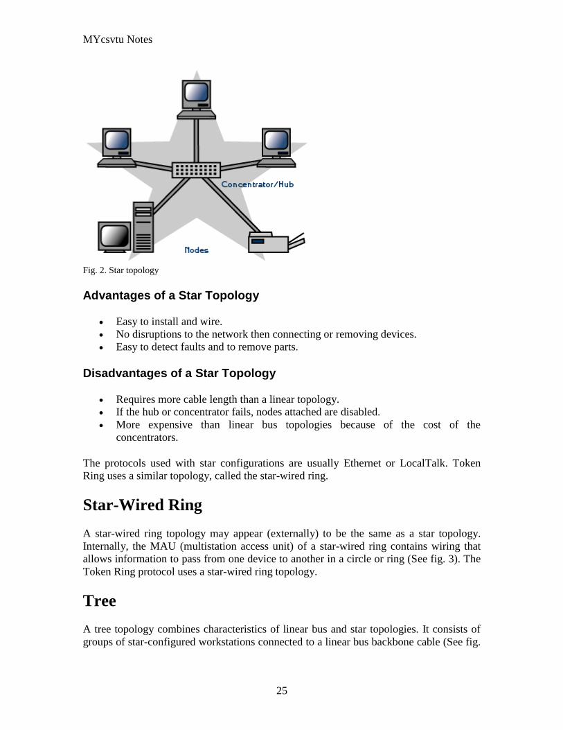
MYcsvtu Notes
25
Fig 2 Star topology
Advantages of a Star Topology
Easy to install and wire
No disruptions to the network then connecting or removing devices
Easy to detect faults and to remove parts
Disadvantages of a Star Topology
Requires more cable length than a linear topology
If the hub or concentrator fails nodes attached are disabled
More expensive than linear bus topologies because of the cost of the
concentrators
The protocols used with star configurations are usually Ethernet or LocalTalk Token
Ring uses a similar topology called the star-wired ring
Star-Wired Ring
A star-wired ring topology may appear (externally) to be the same as a star topology
Internally the MAU (multistation access unit) of a star-wired ring contains wiring that
allows information to pass from one device to another in a circle or ring (See fig 3) The
Token Ring protocol uses a star-wired ring topology
Tree
A tree topology combines characteristics of linear bus and star topologies It consists of
groups of star-configured workstations connected to a linear bus backbone cable (See fig
MYcsvtu Notes
26
4) Tree topologies allow for the expansion of an existing network and enable schools to
configure a network to meet their needs
Fig 4 Tree topology
Advantages of a Tree Topology
Point-to-point wiring for individual segments
Supported by several hardware and software venders
Disadvantages of a Tree Topology
Overall length of each segment is limited by the type of cabling used
If the backbone line breaks the entire segment goes down
More difficult to configure and wire than other topologies
5-4-3 Rule
A consideration in setting up a tree topology using Ethernet protocol is the 5-4-3 rule
One aspect of the Ethernet protocol requires that a signal sent out on the network cable
reach every part of the network within a specified length of time Each concentrator or
repeater that a signal goes through adds a small amount of time This leads to the rule that
between any two nodes on the network there can only be a maximum of 5 segments
connected through 4 repeatersconcentrators In addition only 3 of the segments may be
populated (trunk) segments if they are made of coaxial cable A populated segment is one
which has one or more nodes attached to it In Figure 4 the 5-4-3 rule is adhered to The
MYcsvtu Notes
27
furthest two nodes on the network have 4 segments and 3 repeatersconcentrators
between them
This rule does not apply to other network protocols or Ethernet networks where all fiber
optic cabling or a combination of a fiber backbone with UTP cabling is used If there is a
combination of fiber optic backbone and UTP cabling the rule is simply translated to 7-
6-5 rule
] Mesh
Full
Fully Connected The type of network topology in which each of the nodes of the network is
connected to each of the other nodes in the network with a point-to-point link ndash
this makes it possible for data to be simultaneously transmitted from any single
node to all of the other nodes
Note The physical fully connected mesh topology is generally too costly and
complex for practical networks although the topology is used when there are only
a small number of nodes to be interconnected[3]
Partial
Partially Connected The type of network topology in which some of the nodes of the network are
connected to more than one other node in the network with a point-to-point link ndash
this makes it possible to take advantage of some of the redundancy that is
provided by a physical fully connected mesh topology without the expense and
complexity required for a connection between every node in the network
Note In most practical networks that are based upon the physical partially
connected mesh topology all of the data that is transmitted between nodes in the
network takes the shortest path between nodes except in the case of a failure or
break in one of the links in which case the data takes an alternate path to the
destination ndash this implies that the nodes of the network possess some type of
logical routing algorithm to determine the correct path to use at any particular
time
[edit] Hybrid Network Topologies
The hybrid topology is a type of network topology that is composed of one or more
interconnections of two or more networks that are based upon different physical
topologies or a type of network topology that is composed of one or more
interconnections of two or more networks that are based upon the same physical
topology but where the physical topology of the network resulting from such an
interconnection does not meet the definition of the original physical topology of the
interconnected networks (eg the physical topology of a network that would result from
an interconnection of two or more networks that are based upon the physical star
topology might create a hybrid topology which resembles a mixture of the physical star
MYcsvtu Notes
28
and physical bus topologies or a mixture of the physical star and the physical tree
topologies depending upon how the individual networks are interconnected while the
physical topology of a network that would result from an interconnection of two or more
networks that are based upon the physical distributed bus network retains the topology of
a physical distributed bus network)
Star-Bus A type of network topology in which the central nodes of one or more individual
networks that are based upon the physical star topology are connected together
using a common bus network whose physical topology is based upon the
physical linear bus topology the endpoints of the common bus being terminated
with the characteristic impedance of the transmission medium where required ndash
eg two or more hubs connected to a common backbone with drop cables
through the port on the hub that is provided for that purpose (eg a properly
configured uplink port) would comprise the physical bus portion of the physical
star-bus topology while each of the individual hubs combined with the
individual nodes which are connected to them would comprise the physical star
portion of the physical star-bus topology
Star-of-Stars
Hierarchical Star A type of network topology that is composed of an interconnection of individual
networks that are based upon the physical star topology connected together in a
hierarchical fashion to form a more complex network ndash eg a top level central
node which is the hub of the top level physical star topology and to which other
second level central nodes are attached as the spoke nodes each of which in
turn may also become the central nodes of a third level physical star topology
Notes 1) The physical hierarchical star topology is not a combination of the physical
linear bus and the physical star topologies as cited in some texts as there is no
common linear bus within the topology although the top level hub which is the
beginning of the physical hierarchical star topology may be connected to the
backbone of another network such as a common carrier which is topologically
not considered to be a part of the local network ndash if the top level central node is
connected to a backbone that is considered to be a part of the local network then
the resulting network topology would be considered to be a hybrid topology that
is a mixture of the topology of the backbone network and the physical hierarchical
star topology
2) The physical hierarchical star topology is also sometimes incorrectly referred
to as a physical tree topology since its physical topology is hierarchical however
the physical hierarchical star topology does not have a structure that is determined
by a branching factor as is the case with the physical tree topology and therefore
nodes may be added to or removed from any node that is the hub of one of the
individual physical star topology networks within a network that is based upon the
physical hierarchical star topology
3) The physical hierarchical star topology is commonly used in outside plant
(OSP) cabling to connect various buildings to a central connection facility which
MYcsvtu Notes
29
may also house the demarcation point for the connection to the data transmission
facilities of a common carrier and in inside plant (ISP) cabling to connect
multiple wiring closets within a building to a common wiring closet within the
same building which is also generally where the main backbone or trunk that
connects to a larger network if any enters the building
Star-wired Ring A type of hybrid physical network topology that is a combination of the physical
star topology and the physical ring topology the physical star portion of the
topology consisting of a network in which each of the nodes of which the network
is composed are connected to a central node with a point-to-point link in a hub
and spoke fashion the central node being the hub and the nodes that are
attached to the central node being the spokes (eg a collection of point-to-point
links from the peripheral nodes that converge at a central node) in a fashion that is
identical to the physical star topology while the physical ring portion of the
topology consists of circuitry within the central node which routes the signals on
the network to each of the connected nodes sequentially in a circular fashion
Note In an 8025 Token Ring network the central node is called a Multistation
Access Unit (MAU)
Hybrid Mesh A type of hybrid physical network topology that is a combination of the physical
partially connected topology and one or more other physical topologies the mesh
portion of the topology consisting of redundant or alternate connections between
some of the nodes in the network ndash the physical hybrid mesh topology is
commonly used in networks which require a high degree of availability
Considerations When Choosing a Topology
Money A linear bus network may be the least expensive way to install a network
you do not have to purchase concentrators
Length of cable needed The linear bus network uses shorter lengths of cable
Future growth With a star topology expanding a network is easily done by
adding another concentrator
Cable type The most common cable in schools is unshielded twisted pair which
is most often used with star topologies
Summary Chart
Common Cable Common Protocol
Linear Bus Twisted Pair
Coaxial
Ethernet
LocalTalk
MYcsvtu Notes
30
Fiber
Star Twisted Pair
Fiber
Ethernet
LocalTalk
Star-Wired Ring Twisted Pair Token Ring
Tree
Twisted Pair
Coaxial
Fiber
Ethernet
Internet vs Web
The Internet and the World Wide Web are not synonymous the Internet is a collection of
interconnected computer networks linked by copper wires fiber-optic cables wireless
connections etc the Web is a collection of interconnected documents and other
resources linked by hyperlinks and URLs The World Wide Web is accessible via the
Internet as are many other services including e-mail file sharing and others described
below
The best way to define and distinguish between these terms is to understand the Internet
protocol suite This collection of protocols is organized into layers such that each layer
provides the foundation and the services required by the layer above In this conception
the term Internet refers to computer networks that all communicate with IP (Internet
protocol) and TCP (transfer control protocol) Once this networking structure is
established then other protocols can run ―on top These other protocols are sometimes
called services or applications Hypertext transfer protocol or HTTP is an application
layer protocol that links billions of files together into the World Wide Web
Common uses of the Internet
The World Wide Web
Through keyword-driven Internet research using search engines like Google
millions worldwide have easy instant access to a vast and diverse amount of
online information Compared to encyclopedias and traditional libraries the
World Wide Web has enabled a sudden and extreme decentralization of
information and data
Many individuals and some companies and groups have adopted the use of Web logs or
blogs which are largely used as easily-updatable online diaries Some commercial
organizations encourage staff to fill them with advice on their areas of specialization in
the hope that visitors will be impressed by the expert knowledge and free information
and be attracted to the corporation as a result One example of this practice is Microsoft
MYcsvtu Notes
31
whose product developers publish their personal blogs in order to pique the publics
interest in their work
For more information on the distinction between the World Wide Web and the Internet
itself mdash as in everyday use the two are sometimes confused mdash see Dark internet where
this is discussed in more detail
Remote access
The Internet allows computer users to connect to other computers and information stores
easily wherever they may be across the world They may do this with or without the use
of security authentication and encryption technologies depending on the requirements
This is encouraging new ways of working from home collaboration and information
sharing in many industries An accountant sitting at home can audit the books of a
company based in another country on a server situated in a third country that is remotely
maintained by IT specialists in a fourth These accounts could have been created by
home-working book-keepers in other remote locations based on information e-mailed to
them from offices all over the world Some of these things were possible before the
widespread use of the Internet but the cost of private leased lines would have made
many of them infeasible in practice
An office worker away from his desk perhaps the other side of the world on a business
trip or a holiday can open a remote desktop session into his normal office PC using a
secure Virtual Private Network (VPN) connection via the Internet This gives him
complete access to all his normal files and data including e-mail and other applications
while he is away
This concept is also referred to by some network security people as the Virtual Private
Nightmare because it extends the secure perimeter of a corporate network into its
employees homes this has been the source of some notable security breaches but also
provides security for the workers
Functions
File-sharing
Instant messaging
Internet fax
Search engine
World Wide Web
MYcsvtu Notes
32
Intranets
What are Intranets
bull Intranet is Intra+ Net so an Intranet is an internal or private Internet used strictly
within the confines of a company university or organization Inter means
between or among hence the difference between the Internet and an Intranet
Some formal definitions of Intranets
bull Brown amp Duguid ―Intranets help present and
circulate boundary objects
bull Choo Detlor amp Turnbull ―Intranetshellip support the creation sharing and use of
knowledge
bull Stenmark ―Intranets are organizationally
restricted
A technical definition
bull An Intranet is a network based on the internet TCPIP open standard An intranet
belongs to an organization and is designed to be accessible only by the
organizations members employees or others with authorization An intranets
Web site looks and act just like other Web sites but has a firewall surrounding it
to fend off unauthorized users
Design Of Intranets
Steps
bull Analyze the organizationlsquos information ecology
bull Identify the typical problems experienced by users
bull Analyze the information behaviors of these set of users
bull Create value added processes to resolve the problems of users and to improve the
Information Ecology
Value Added Processes
bull Intranets may be designed to improve the organizational information ecology
MYcsvtu Notes
33
bull Intranets provide a unified information space in which users can communicate
and collaborate with others
bull intranet applications and services may add value by supporting the organizationlsquos
knowledge creating and decision making process
Two Models of Online Environments
Centralized
Distributed
Centralized Environments
bull Before the web the centralized model was all we had (examples include
CompuServe Prodigy)
bull On the web centralized models include site-based services such as Yahoo
bull Most (all) college and university services are offered using the centralized
model
MYcsvtu Notes
34
bull But centralized environments are static inflexible expensive
Distributed Environments
bull The World Wide Web is an example of a distributed environment
bull Resources access are not centralized but scattered around the world
ndash Resources in the form of a network of connected (via DNS) web servers
ndash Access in the form of a network of connected (via DNS) internet service
providers
ndash Users in the form of individualized and connected (via HTTP) web
browsers
bull The big issue ndash integration ndash that is making different systems work together
Design Principles
Network Design Principles
ndash Specifies how networks differ from traditional learning
ndash The idea is that each principle confers an advantage over non-network
systems
ndash Can be used as a means of evaluating new technology
1 Decentralize
ndash Centralized networks have a characteristic starlsquo shape
bull Some entities have many connections
bull The vast majority have few
bull Eg broadcast network teacher in a classroom
ndash Decentralized networks form a mesh
bull The weight of connections flow is distributed
bull Balanced load = more stable
bull Foster connections between entities fill outlsquo the star
Distribute
ndash Network entities reside in different physical locations
bull Reduces risk of network failure
bull Reduces need for major infrastructure such as powerful servers
large bandwidth massive storage
ndash Examples
bull Peer-to-peer networks such as Kazaa Gnutella
bull Content syndication networks such as RSS
ndash Emphasis is on sharing not copying
bull Locallsquo copies are temporary
MYcsvtu Notes
35
Computer Graphics
Computer Graphics is about animation (films)
Games are very important in Computer Graphics
Medical Imaging is another driving force
Computer Aided Design too
Graphics Definitions
bull Point
ndash a location in space 2D or 3D
ndash sometimes denotes one pixel
bull Line
ndash straight path connecting two points
ndash infinitesimal width consistent density
ndash beginning and end on points
bull Vertex
ndash point in 3D
bull Edge
ndash line in 3D connecting two vertices
bull PolygonFaceFacet
ndash arbitrary shape formed by connected vertices
ndash fundamental unit of 3D computer graphics
bull Raster
ndash derived from TV systems for a row of pixels
ndash commonly referred to as a scanline
ndash does influence algorithms ndash reducing memory requirements parallelism
etc
ndash is the derivation of rasterization scan-line algorithms
Displays
bull Most desktop displays use a cathode ray tube (CRT) while portable computing
devices such as laptops incorporate liquid crystal display (LCD)
bull Because of their slimmer design and smaller energy consumption monitors using
LCD technologies are beginning to replace the venerable CRT on many desktops
Cathode-Ray Tubes
MYcsvtu Notes
36
bull Classical output device is a monitor
bull Cathode-Ray Tube (CRT)
ndash Invented by Karl Ferdinand Braun (1897)
ndash Beam of electrons directed from cathode (-)to phosphor-coated
(fluorescent) screen (anode (+))
ndash Directed by magnetic focusing and deflection coils (anodes) in vacuum
filled tube
ndash Phosphor emits photon of light when hit by an electron of varied
persistence (long 15-20 ms for texts short lt 1ms for animation)
ndash Refresh rate (50-60 Hz 72-76 Hz) to avoid flicker trail
ndash Phosphors are organic compounds characterized by their persistence and
their color (blue red green)
Cathode-Ray Tubes
bull Cathode-Ray Tube (CRT)
ndash Horizontal deflection and vertical deflection direct the electron beam to
any point on the screen
ndash Intensity knob regulates the flow of electrons by controlling the voltage at
the control grid (high voltage reduces the electron density and thus
brightness)
ndash Accelerating voltage from positive coating inside screen (anode screen) or
an accelerating anode
bull Image maintenance
ndash Charge distribution to store picture information
OR
ndash Refresh CRT refreshes the display constantly to maintain phosphor glow
Cathode-Ray Tubes
bullCathode-Ray Tube (CRT)
ndash Horizontal deflection and vertical deflection direct the electron beam to any point
on the screen
ndash Intensity knob regulates the flow of electrons by controlling the voltage at the
control grid (high voltage reduces the electron density and thus brightness)
ndash Accelerating voltage from positive coating inside screen (anode screen) or an
accelerating anode
bullImage maintenance
ndash Charge distribution to store picture information
OR
ndash Refresh CRT refreshes the display constantly to maintain phosphor glow
bull Characteristics of Cathode-Ray Tube (CRT)
MYcsvtu Notes
37
ndash Intensity is proportional to the number of electrons repelled in beam per
second (brightness)
ndash Resolution is the maximum number of points that can be displayed
without overlap is expressed as number of horizontal points by number of
vertical points points are called pixels (picture elements) example
resolution 1024 x 768 pixels Typical resolution is 1280 x 1024 pixels
bull High-definition systems high resolution systems
bull Focusing
ndash Focusing forces the electron beam to converge to a point on the monitor
screen
ndash Can be electrostatic (lens) or magnetic (field)
bull Deflection
ndash Deflection directs the electron beam horizontally andor vertically to any
point on the screen
ndash Can be controlled by electric (deflection plates slide 9) or magnetic fields
(deflection coils slide 5)
ndash Magnetic coils two pairs (topbottom leftright) of tube neck
ndash Electric plates two pairs (horizontal vertical)
Raster-scan Displays
bullVideo displays can be either raster-scan or random-scan displays
bullRaster-scan display is the most common type of monitor using a CRT
bullThe electron beam scans the screen from top to bottom one row at a time Each row is
called a scan line
bullThe electron beam is turned on and off to produce a collection of dots painted one row at
a time These will form the image
bullA raster is a matrix of pixels covering the screen area and is composed of raster lines
Raster-scan Displays
MYcsvtu Notes
38
Raster-scan Displays
bullThe image is stored in a frame buffer containing the total screen area and where each
memory location corresponds to a pixel
bullIn a monochrome system each bit is 1 or 0 for the corresponding pixel to be on or off
(bitmap)
bullThe display processor scans the frame buffer to turn electron beam onoff depending if
the bit is 1 or 0
bullFor color monitors the frame buffer also contains the color of each pixel (color buffer)
as well as other characteristics of the image (gray scale hellip) 8 bitspixel 0255
(pixmap)
bullDepth of the buffer area is the number of bits per pixel (bit planes) up to 24
bullExamples television panels printers PC monitors (99 of raster-scan)
Raster-scan Displays
bullRefresh rate 24 is a minimum to avoid flicker corresponding to 24 Hz (1 Hz = 1 refresh
per second)
bullCurrent raster-scan displays have a refresh rate of at least 60 frames (60 Hz) per second
up to 120 (120 Hz)
bullUses large memory 640x480 307200 bits 38 kB
bullRefresh procedure
MYcsvtu Notes
39
ndashHorizontal retrace ndash beam returns to left of screen
ndashVertical retrace ndash bean returns to top left corner of screen
ndashInterlaced refresh ndash display first even-numbered lines then odd-numbered lines
permits to see the image in half the time
useful for slow refresh rates (30 Hz shows as 60 Hz)
Random-scan Displays
bullRandom scan systems are also called vector stroke-writing or calligraphic displays
bullThe electron beam directly draws the picture in any specified order
bullA pen plotter is an example of such a system
bullPicture is stored in a display list refresh display file vector file or display program as a
set of line drawing commands
bullRefreshes by scanning the list 30 to 60 times per second
bullMore suited for line-drawing applications such as architecture and manufacturing
Random-scan Displays
bullAdvantages
ndashHigh resolution
ndashEasy animation
ndashRequires little memory
bullDisadvantages
ndashRequires intelligent electron beam (processor controlled)
ndashLimited screen density limited to simple line-based images
ndashLimited color capability
bullImproved in the 1960lsquos by the Direct View Storage Tube (DVST) from Tektronix
Color CRT Monitor
Uses different phosphors a combination of Red Green and Blue to produce any color
Two methods
Random scan uses beam penetration
2 layers (Red Green) phosphors low speed electrons excite Red high speed electrons
excite Green interrmediate speed excite both to get yellow and orange Color is
controlled by electron beam voltage
Only produces a restricted set of colors
Raster scan uses a shadow mask with three electron guns Red Green and Blue (RGB
color model) Color is produced by adjusting the intensity level of each electron beam
Produces a wide range of colors from 8 to several millions
Raster scan
Most common as found in televisions
Beam scanned left to right flicked back to rescan from top to bottom then repeated
Repeated at 30Hz per frame sometimes higher to reduce flicker Interlacing scanning
MYcsvtu Notes
40
odd lines in whole screen then even lines is also used to reduce flicker Can also use
high-persistence phosphor to reduce flicker but causes image smearing especially with
significant animation
Resolution typically 512x512 but high-quality screens are available (and becoming more
common) at up to approximately 1600x1200 pixels Sun workstations have screens of
1192x980 pixels
Black amp white screens can display grayscale by varying the intensity of the electron
beam
Colour is achieved using three electron guns which hit red green or blue phosphors
Combining these colours can produce many others including white (all on) Phosphor
dots focused using a shadow mask - makes colour screens lower resolution than
monochrome
Alternative approach beam penetration Special phosphor glows a different colour
depending on intensity of beam
Colour or intensity at pixel held by computerlsquos video card 1 bitpixel can store offon
information hence only black ampwhite More bitspixel give rise to more colour
possibilities eg 8 bitspixel gives rise to 2^8=256 possible colours at any one time
Random Scan (Directed-beam refresh vector display)
Instead of scanning the whole display sequentially and horizontally the random scan
draws the lines to be displayed directly Screen update at gt30Hz to reduce flicker
Jaggies not found and higher resolutions possible (up to 4096x4096 pixels) Colour
achieved using beam penetration generally of poorer quality Eye strain and fatigue still
a problem and vector displays are more expensive
Direct view storage tube (DVST)
Used a lot in analogue storage oscilloscopes
Similar to random scan crt but image maintained by flood guns - no flicker Can be
incrementally updated but not selectively erased image has to be redrawn on completely
erased screen High resolution (typically 4096x3120 pixels) but low contrast low
brightness and difficulty in displaying colour
What is a Multimedia System
bull A system that involves
ndash generation
ndash representation
ndash storage
ndash transmission
ndash search and retrieval
ndash delivery
MYcsvtu Notes
41
of multimedia information
productionauthoring tools
compression and formats
file system design
networking issues
database management
server design streaming
Multimedia System Architecture
Information management subsystem Presentation Query
Storage subsystem Efficiently stored
amp retrieved
Network subsystem Delivery
Adaptation in Multimedia Systems
bull Multimedia systems can profit a lot from personalization
ndash User behavior
ndash User properties
bull Adaptation
ndash Models
ndash Mechanisms
Multimedia in a mobile environment
MYcsvtu Notes
42
bull Applications
ndash Emergency response systems mobile commerce phone service
entertainment games
What is Sound
A ripple is a pressure wave in water created by an object striking the water
Sound is a pressure wave in air created for example by an object such as a string
or our vocal cords vibrating Dark here represents more pressure light represents
less
MYcsvtu Notes
43
Sine Waves Form Pure Tones
This simple sound wave is a Sine Wave a Pure tone produced by a simple vibration
Sine Wave Sample Tone
This can be represented graphically as shown above
Converting Pressure into Voltage
The pressure wave of sound moves a diaphragm in the microphone which produces a
voltage proportional to the pressure of the sound wave at each instant
Animation
MYcsvtu Notes
44
bull Animation is the rapid display of a sequence of images of 2-D artwork or model
positions in order to create an illusion of movement It is an optical illusion of
motion due to the phenomenon of persistence of vision This could be anything
from a flip book to a motion picture film Animation deals with the generation
sequencing and display a set of images which is called frames to create an effect
of visual change or motion similar to a movie film
bull Animation is used in those instance where videography is not possible
Hardware Requirement For Animation
bull Image Generation Tools amp Devices
bull Computer monitors with image display Capability
Software Requirement For Animation
bull Animation creating software
bull Screen Capture Software
bull Animation Clips
bull Software support For High Resolution
bull Recording amp Playback Capability
bull Transition effect
Early animation
There is no single person that can be considered the creator of the art of animation as
there were several people doing several projects which could be considered various types
of animation all around the same time (Short hand-drawn animation scenes could be
presented with the Phenakistoscope the Zoetrope and other optical toys already in the
early 1800s)
The following is a brief listing on those who are often acknowledged as significant to the
development of animation Note that this list is by no means a comprehensive list of
contributors to early animation
Georges Meacuteliegraves was a creator of special effect films such as A Trip to the Moon He
used many techniques ndash one of which was to stop the camera rolling change something
in the scene and then continue rolling the film This is a very similar idea to that of stop-
motion animation Meacuteliegraves accidentally happened upon the technique when his camera
broke down while shooting a bus driving by When the camera was fixed a horse
happened to be passing by just as Meacuteliegraves continued to film The result was that the bus
appeared to change into a horse
MYcsvtu Notes
45
Fantasmagorie by Emile Cohl 1908
Eacutemile Cohl began drawing cartoon strips and created a film in 1908 called
Fantasmagorie The film largely consisted of a stick figure moving about and
encountering all manner of morphing objects such as a wine bottle that transforms into a
flower There were also sections of live action where the animatorlsquos hands would enter
the scene The film was created by drawing each frame on paper and then shooting each
frame onto negative film which gave the picture a blackboard look
Winsor McCay created detailed animations that required a team of artists and painstaking
attention for detail Each frame was drawn on paper requiring backgrounds to be
redrawn as well characters to be animated His films such as Gertie the Dinosaur (1914)
and The Sinking of the Lusitania (1918) were of an impressive scale although The
Sinking of the Lusitania used cels
In 1919 Otto Messmer created the character of Felix the cat for Pat Sullivans animation
studios The importance of Felix lies in the characters strong personality created largely
through gesture and actions
Animation techniques
Animation techniques are incredibly varied and difficult to categorize Techniques are
often related or combined The following is a brief on common types of animation
Again this list is by no means comprehensive
Traditional animation
An example of traditional animation a horse animated by rotoscoping from Edweard
Muybridges 19th century photos
Main article Traditional animation
MYcsvtu Notes
46
Also called cel animation the frames of a traditionally animated movie are hand-drawn
The drawings are traced or copied onto transparent acetate sheets called cels which are
then placed over a painted background and photographed one by one on a rostrum
camera Nowadays the use of cels (and cameras) is mostly obsolete since the drawings
are scanned into computers and digitally transferred directly to 35 mm film The look
of traditional cel animation is still preserved and the character animators work has
remained essentially the same over the past 70 years Because of the digital influence
over modern cel animation it is also known as tradigital animation
Examples The Lion King Spirited Away Les Triplettes de Belleville
Full animation The most common style in animation known for its realistic and often very detailed art
Examples All Disney feature length animated films The Secret of NIMH The Iron Giant
Limited animation A cheaper process of making animated cartoons that does not follow a realistic
approach
Examples The Flintstones Yellow Submarine
Rubber hose The characters are usually cartoony and the animators have a lot of artistic freedom as
rubber hose animations dont have to follow the laws of physics and anatomy in the same
degree as the other main styles in animation
Examples Early Mickey Mouse cartoons Ren and Stimpy Popeye
Rotoscoping A technique where animators trace live action movement frame by frame for use in
animated films
Examples Gullivers Travels American Pop
Stop motion
Stop-motion animation is any type of animation which requires the animator to physically
alter the scene shoot a frame again alter the scene and shoot a frame and so on to create
the animation There are many different types of stop-motion animation some noteable
examples are listed below
Clay animation
MYcsvtu Notes
47
A clay animation scene from a TV commercial
Often abbreviated to claymation this is a type of stop-motion animation using
figures made of clay or a similar malleable material The figures may have an
armature or wire frame inside of them similar to puppet animation (below)
Alternatively the figures may be made entirely of clay such as in the films of
Bruce Bickford where clay creatures morph into a variety of different shapes
Examples Wallace and Gromit Dimensions of Dialogue by Jan Švankmajer The
Amazing Mr Bickford The Trap Door
Cutout animation In this type of stop-motion animation the animation is formed by moving 2-
dimensional pieces of material such as paper or cloth
Examples the animated sequences of Monty Pythons Flying Circus (often
referred to as Dada animation named after the Dada art movement[citation needed]
)
Tale of Tales early episodes of South Park
Silhouette animation A type of cutout animation where the viewer only sees black silhouettes
Example The Adventures of Prince Achmed the worlds oldest surviving
animated feature film from 1926
Graphic animation
Model animation In this form of animation model animated characters interact with and are a part
of the live-action world
Examples The films of Ray Harryhausen (Jason and the Argonauts) and Willis
OBrien (King Kong)
Go motion
Object animation
Pixilation Examples Neighbours
Puppet animation Puppet animation typically involves puppet figures interacting with each other in
a constructed environment in contrast to the real-world interaction in model
MYcsvtu Notes
48
animation (above) The puppets generally have an armature inside of them to
keep them still and steady as well as constraining them to move at particular
joints
Examples The Nightmare Before Christmas Robot Chicken The Tale of the Fox
Brickfilm
Puppetoon
Computer animation
A short gif animation
Like stop motion computer animation encompasses a variety of techniques the unifying
idea being that the animation is created digitally on a computer
2D animation Figures are created andor edited on the computer using 2D bitmap graphics or
created and edited using 2D vector graphics This includes automated
computerized versions of traditional animation techniques such as of tweening
morphing onion skinning and interpolated rotoscoping
Examples A Scanner Darkly Jib Jab
Analog computer animation
Flash animation
PowerPoint animation
A completely synthetic computer-generated scene
3D animation
MYcsvtu Notes
49
Figures are created in the computer using polygons To allow these meshes to
move they are given a digital armature (sculpture) This process is called rigging
Various other techniques can be applied such as mathematical functions
(gravity) simulated fur or hair effects such as fire and water and the use of
motion capture to name but a few
Examples The Incredibles Shrek
Cel-shaded animation
Morph target animation
Skeletal animation
Motion capture
Crowd simulation
Less common techniques
Drawn on film animation A technique where footage is produced by creating the
images directly on film stock
Paint-on-glass animationA technique for making animated films by manipulating slow-
drying oil paints on sheets of glass
Pinscreen animation Makes use of a screen filled with movable pins which can be
moved in or out by pressing an object onto the screen The screen is lit from the side so
that the pins cast shadows The technique has been used to create animated films with a
range of textural effects difficult to achieve with traditional cel animation
Sand animation Sand is moved around on a backlighted or frontlighted piece of glass to
create each frame for an animated film
Multimedia
Multimedia (Lat Multum + Medium) is media that uses multiple forms of information
content and information processing (eg text audio graphics animation video
interactivity) to inform or entertain the (user) audience Multimedia also refers to the use
of (but not limited to) electronic media to store and experience multimedia content
Multimedia is similar to traditional mixed media in fine art but with a broader scope The
term rich media is synonymous for interactive multimedia
Categorization
Multimedia may be broadly divided into linear and non-linear categories Linear active
content progresses without any navigation control for the viewer such as a cinema
presentation Non-linear content offers user interactivity to control progress as used with
MYcsvtu Notes
50
a computer game or used in self-paced computer based training Non-linear content is
also known as hypermedia content
Multimedia presentations can be live or recorded A recorded presentation may allow
interactivity via a navigation system A live multimedia presentation may allow
interactivity via interaction with the presenter or performer
There are 2 basic way to represent some information
Unimedium Presentation
Multimedia Presentation
In case of computer system the commonly used medioa for the purpose of storage
access and transmission of information are
bull Text
bull Graphics
bull Animation
bull Audio
bull Video
Multimedia Computer System require
bull Faster CPU
bull Larger Storage Devices
bull Larger Main Memory
bull Good Graphics Terminal
bull IO devices required to play an audio associated with the program
Transmission Mode
bull Asynchronous
bull Synchronous
bull Isochronous
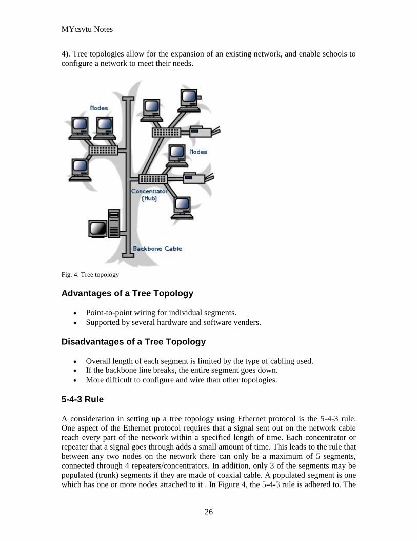
MYcsvtu Notes
26
4) Tree topologies allow for the expansion of an existing network and enable schools to
configure a network to meet their needs
Fig 4 Tree topology
Advantages of a Tree Topology
Point-to-point wiring for individual segments
Supported by several hardware and software venders
Disadvantages of a Tree Topology
Overall length of each segment is limited by the type of cabling used
If the backbone line breaks the entire segment goes down
More difficult to configure and wire than other topologies
5-4-3 Rule
A consideration in setting up a tree topology using Ethernet protocol is the 5-4-3 rule
One aspect of the Ethernet protocol requires that a signal sent out on the network cable
reach every part of the network within a specified length of time Each concentrator or
repeater that a signal goes through adds a small amount of time This leads to the rule that
between any two nodes on the network there can only be a maximum of 5 segments
connected through 4 repeatersconcentrators In addition only 3 of the segments may be
populated (trunk) segments if they are made of coaxial cable A populated segment is one
which has one or more nodes attached to it In Figure 4 the 5-4-3 rule is adhered to The
MYcsvtu Notes
27
furthest two nodes on the network have 4 segments and 3 repeatersconcentrators
between them
This rule does not apply to other network protocols or Ethernet networks where all fiber
optic cabling or a combination of a fiber backbone with UTP cabling is used If there is a
combination of fiber optic backbone and UTP cabling the rule is simply translated to 7-
6-5 rule
] Mesh
Full
Fully Connected The type of network topology in which each of the nodes of the network is
connected to each of the other nodes in the network with a point-to-point link ndash
this makes it possible for data to be simultaneously transmitted from any single
node to all of the other nodes
Note The physical fully connected mesh topology is generally too costly and
complex for practical networks although the topology is used when there are only
a small number of nodes to be interconnected[3]
Partial
Partially Connected The type of network topology in which some of the nodes of the network are
connected to more than one other node in the network with a point-to-point link ndash
this makes it possible to take advantage of some of the redundancy that is
provided by a physical fully connected mesh topology without the expense and
complexity required for a connection between every node in the network
Note In most practical networks that are based upon the physical partially
connected mesh topology all of the data that is transmitted between nodes in the
network takes the shortest path between nodes except in the case of a failure or
break in one of the links in which case the data takes an alternate path to the
destination ndash this implies that the nodes of the network possess some type of
logical routing algorithm to determine the correct path to use at any particular
time
[edit] Hybrid Network Topologies
The hybrid topology is a type of network topology that is composed of one or more
interconnections of two or more networks that are based upon different physical
topologies or a type of network topology that is composed of one or more
interconnections of two or more networks that are based upon the same physical
topology but where the physical topology of the network resulting from such an
interconnection does not meet the definition of the original physical topology of the
interconnected networks (eg the physical topology of a network that would result from
an interconnection of two or more networks that are based upon the physical star
topology might create a hybrid topology which resembles a mixture of the physical star
MYcsvtu Notes
28
and physical bus topologies or a mixture of the physical star and the physical tree
topologies depending upon how the individual networks are interconnected while the
physical topology of a network that would result from an interconnection of two or more
networks that are based upon the physical distributed bus network retains the topology of
a physical distributed bus network)
Star-Bus A type of network topology in which the central nodes of one or more individual
networks that are based upon the physical star topology are connected together
using a common bus network whose physical topology is based upon the
physical linear bus topology the endpoints of the common bus being terminated
with the characteristic impedance of the transmission medium where required ndash
eg two or more hubs connected to a common backbone with drop cables
through the port on the hub that is provided for that purpose (eg a properly
configured uplink port) would comprise the physical bus portion of the physical
star-bus topology while each of the individual hubs combined with the
individual nodes which are connected to them would comprise the physical star
portion of the physical star-bus topology
Star-of-Stars
Hierarchical Star A type of network topology that is composed of an interconnection of individual
networks that are based upon the physical star topology connected together in a
hierarchical fashion to form a more complex network ndash eg a top level central
node which is the hub of the top level physical star topology and to which other
second level central nodes are attached as the spoke nodes each of which in
turn may also become the central nodes of a third level physical star topology
Notes 1) The physical hierarchical star topology is not a combination of the physical
linear bus and the physical star topologies as cited in some texts as there is no
common linear bus within the topology although the top level hub which is the
beginning of the physical hierarchical star topology may be connected to the
backbone of another network such as a common carrier which is topologically
not considered to be a part of the local network ndash if the top level central node is
connected to a backbone that is considered to be a part of the local network then
the resulting network topology would be considered to be a hybrid topology that
is a mixture of the topology of the backbone network and the physical hierarchical
star topology
2) The physical hierarchical star topology is also sometimes incorrectly referred
to as a physical tree topology since its physical topology is hierarchical however
the physical hierarchical star topology does not have a structure that is determined
by a branching factor as is the case with the physical tree topology and therefore
nodes may be added to or removed from any node that is the hub of one of the
individual physical star topology networks within a network that is based upon the
physical hierarchical star topology
3) The physical hierarchical star topology is commonly used in outside plant
(OSP) cabling to connect various buildings to a central connection facility which
MYcsvtu Notes
29
may also house the demarcation point for the connection to the data transmission
facilities of a common carrier and in inside plant (ISP) cabling to connect
multiple wiring closets within a building to a common wiring closet within the
same building which is also generally where the main backbone or trunk that
connects to a larger network if any enters the building
Star-wired Ring A type of hybrid physical network topology that is a combination of the physical
star topology and the physical ring topology the physical star portion of the
topology consisting of a network in which each of the nodes of which the network
is composed are connected to a central node with a point-to-point link in a hub
and spoke fashion the central node being the hub and the nodes that are
attached to the central node being the spokes (eg a collection of point-to-point
links from the peripheral nodes that converge at a central node) in a fashion that is
identical to the physical star topology while the physical ring portion of the
topology consists of circuitry within the central node which routes the signals on
the network to each of the connected nodes sequentially in a circular fashion
Note In an 8025 Token Ring network the central node is called a Multistation
Access Unit (MAU)
Hybrid Mesh A type of hybrid physical network topology that is a combination of the physical
partially connected topology and one or more other physical topologies the mesh
portion of the topology consisting of redundant or alternate connections between
some of the nodes in the network ndash the physical hybrid mesh topology is
commonly used in networks which require a high degree of availability
Considerations When Choosing a Topology
Money A linear bus network may be the least expensive way to install a network
you do not have to purchase concentrators
Length of cable needed The linear bus network uses shorter lengths of cable
Future growth With a star topology expanding a network is easily done by
adding another concentrator
Cable type The most common cable in schools is unshielded twisted pair which
is most often used with star topologies
Summary Chart
Common Cable Common Protocol
Linear Bus Twisted Pair
Coaxial
Ethernet
LocalTalk
MYcsvtu Notes
30
Fiber
Star Twisted Pair
Fiber
Ethernet
LocalTalk
Star-Wired Ring Twisted Pair Token Ring
Tree
Twisted Pair
Coaxial
Fiber
Ethernet
Internet vs Web
The Internet and the World Wide Web are not synonymous the Internet is a collection of
interconnected computer networks linked by copper wires fiber-optic cables wireless
connections etc the Web is a collection of interconnected documents and other
resources linked by hyperlinks and URLs The World Wide Web is accessible via the
Internet as are many other services including e-mail file sharing and others described
below
The best way to define and distinguish between these terms is to understand the Internet
protocol suite This collection of protocols is organized into layers such that each layer
provides the foundation and the services required by the layer above In this conception
the term Internet refers to computer networks that all communicate with IP (Internet
protocol) and TCP (transfer control protocol) Once this networking structure is
established then other protocols can run ―on top These other protocols are sometimes
called services or applications Hypertext transfer protocol or HTTP is an application
layer protocol that links billions of files together into the World Wide Web
Common uses of the Internet
The World Wide Web
Through keyword-driven Internet research using search engines like Google
millions worldwide have easy instant access to a vast and diverse amount of
online information Compared to encyclopedias and traditional libraries the
World Wide Web has enabled a sudden and extreme decentralization of
information and data
Many individuals and some companies and groups have adopted the use of Web logs or
blogs which are largely used as easily-updatable online diaries Some commercial
organizations encourage staff to fill them with advice on their areas of specialization in
the hope that visitors will be impressed by the expert knowledge and free information
and be attracted to the corporation as a result One example of this practice is Microsoft
MYcsvtu Notes
31
whose product developers publish their personal blogs in order to pique the publics
interest in their work
For more information on the distinction between the World Wide Web and the Internet
itself mdash as in everyday use the two are sometimes confused mdash see Dark internet where
this is discussed in more detail
Remote access
The Internet allows computer users to connect to other computers and information stores
easily wherever they may be across the world They may do this with or without the use
of security authentication and encryption technologies depending on the requirements
This is encouraging new ways of working from home collaboration and information
sharing in many industries An accountant sitting at home can audit the books of a
company based in another country on a server situated in a third country that is remotely
maintained by IT specialists in a fourth These accounts could have been created by
home-working book-keepers in other remote locations based on information e-mailed to
them from offices all over the world Some of these things were possible before the
widespread use of the Internet but the cost of private leased lines would have made
many of them infeasible in practice
An office worker away from his desk perhaps the other side of the world on a business
trip or a holiday can open a remote desktop session into his normal office PC using a
secure Virtual Private Network (VPN) connection via the Internet This gives him
complete access to all his normal files and data including e-mail and other applications
while he is away
This concept is also referred to by some network security people as the Virtual Private
Nightmare because it extends the secure perimeter of a corporate network into its
employees homes this has been the source of some notable security breaches but also
provides security for the workers
Functions
File-sharing
Instant messaging
Internet fax
Search engine
World Wide Web
MYcsvtu Notes
32
Intranets
What are Intranets
bull Intranet is Intra+ Net so an Intranet is an internal or private Internet used strictly
within the confines of a company university or organization Inter means
between or among hence the difference between the Internet and an Intranet
Some formal definitions of Intranets
bull Brown amp Duguid ―Intranets help present and
circulate boundary objects
bull Choo Detlor amp Turnbull ―Intranetshellip support the creation sharing and use of
knowledge
bull Stenmark ―Intranets are organizationally
restricted
A technical definition
bull An Intranet is a network based on the internet TCPIP open standard An intranet
belongs to an organization and is designed to be accessible only by the
organizations members employees or others with authorization An intranets
Web site looks and act just like other Web sites but has a firewall surrounding it
to fend off unauthorized users
Design Of Intranets
Steps
bull Analyze the organizationlsquos information ecology
bull Identify the typical problems experienced by users
bull Analyze the information behaviors of these set of users
bull Create value added processes to resolve the problems of users and to improve the
Information Ecology
Value Added Processes
bull Intranets may be designed to improve the organizational information ecology
MYcsvtu Notes
33
bull Intranets provide a unified information space in which users can communicate
and collaborate with others
bull intranet applications and services may add value by supporting the organizationlsquos
knowledge creating and decision making process
Two Models of Online Environments
Centralized
Distributed
Centralized Environments
bull Before the web the centralized model was all we had (examples include
CompuServe Prodigy)
bull On the web centralized models include site-based services such as Yahoo
bull Most (all) college and university services are offered using the centralized
model
MYcsvtu Notes
34
bull But centralized environments are static inflexible expensive
Distributed Environments
bull The World Wide Web is an example of a distributed environment
bull Resources access are not centralized but scattered around the world
ndash Resources in the form of a network of connected (via DNS) web servers
ndash Access in the form of a network of connected (via DNS) internet service
providers
ndash Users in the form of individualized and connected (via HTTP) web
browsers
bull The big issue ndash integration ndash that is making different systems work together
Design Principles
Network Design Principles
ndash Specifies how networks differ from traditional learning
ndash The idea is that each principle confers an advantage over non-network
systems
ndash Can be used as a means of evaluating new technology
1 Decentralize
ndash Centralized networks have a characteristic starlsquo shape
bull Some entities have many connections
bull The vast majority have few
bull Eg broadcast network teacher in a classroom
ndash Decentralized networks form a mesh
bull The weight of connections flow is distributed
bull Balanced load = more stable
bull Foster connections between entities fill outlsquo the star
Distribute
ndash Network entities reside in different physical locations
bull Reduces risk of network failure
bull Reduces need for major infrastructure such as powerful servers
large bandwidth massive storage
ndash Examples
bull Peer-to-peer networks such as Kazaa Gnutella
bull Content syndication networks such as RSS
ndash Emphasis is on sharing not copying
bull Locallsquo copies are temporary
MYcsvtu Notes
35
Computer Graphics
Computer Graphics is about animation (films)
Games are very important in Computer Graphics
Medical Imaging is another driving force
Computer Aided Design too
Graphics Definitions
bull Point
ndash a location in space 2D or 3D
ndash sometimes denotes one pixel
bull Line
ndash straight path connecting two points
ndash infinitesimal width consistent density
ndash beginning and end on points
bull Vertex
ndash point in 3D
bull Edge
ndash line in 3D connecting two vertices
bull PolygonFaceFacet
ndash arbitrary shape formed by connected vertices
ndash fundamental unit of 3D computer graphics
bull Raster
ndash derived from TV systems for a row of pixels
ndash commonly referred to as a scanline
ndash does influence algorithms ndash reducing memory requirements parallelism
etc
ndash is the derivation of rasterization scan-line algorithms
Displays
bull Most desktop displays use a cathode ray tube (CRT) while portable computing
devices such as laptops incorporate liquid crystal display (LCD)
bull Because of their slimmer design and smaller energy consumption monitors using
LCD technologies are beginning to replace the venerable CRT on many desktops
Cathode-Ray Tubes
MYcsvtu Notes
36
bull Classical output device is a monitor
bull Cathode-Ray Tube (CRT)
ndash Invented by Karl Ferdinand Braun (1897)
ndash Beam of electrons directed from cathode (-)to phosphor-coated
(fluorescent) screen (anode (+))
ndash Directed by magnetic focusing and deflection coils (anodes) in vacuum
filled tube
ndash Phosphor emits photon of light when hit by an electron of varied
persistence (long 15-20 ms for texts short lt 1ms for animation)
ndash Refresh rate (50-60 Hz 72-76 Hz) to avoid flicker trail
ndash Phosphors are organic compounds characterized by their persistence and
their color (blue red green)
Cathode-Ray Tubes
bull Cathode-Ray Tube (CRT)
ndash Horizontal deflection and vertical deflection direct the electron beam to
any point on the screen
ndash Intensity knob regulates the flow of electrons by controlling the voltage at
the control grid (high voltage reduces the electron density and thus
brightness)
ndash Accelerating voltage from positive coating inside screen (anode screen) or
an accelerating anode
bull Image maintenance
ndash Charge distribution to store picture information
OR
ndash Refresh CRT refreshes the display constantly to maintain phosphor glow
Cathode-Ray Tubes
bullCathode-Ray Tube (CRT)
ndash Horizontal deflection and vertical deflection direct the electron beam to any point
on the screen
ndash Intensity knob regulates the flow of electrons by controlling the voltage at the
control grid (high voltage reduces the electron density and thus brightness)
ndash Accelerating voltage from positive coating inside screen (anode screen) or an
accelerating anode
bullImage maintenance
ndash Charge distribution to store picture information
OR
ndash Refresh CRT refreshes the display constantly to maintain phosphor glow
bull Characteristics of Cathode-Ray Tube (CRT)
MYcsvtu Notes
37
ndash Intensity is proportional to the number of electrons repelled in beam per
second (brightness)
ndash Resolution is the maximum number of points that can be displayed
without overlap is expressed as number of horizontal points by number of
vertical points points are called pixels (picture elements) example
resolution 1024 x 768 pixels Typical resolution is 1280 x 1024 pixels
bull High-definition systems high resolution systems
bull Focusing
ndash Focusing forces the electron beam to converge to a point on the monitor
screen
ndash Can be electrostatic (lens) or magnetic (field)
bull Deflection
ndash Deflection directs the electron beam horizontally andor vertically to any
point on the screen
ndash Can be controlled by electric (deflection plates slide 9) or magnetic fields
(deflection coils slide 5)
ndash Magnetic coils two pairs (topbottom leftright) of tube neck
ndash Electric plates two pairs (horizontal vertical)
Raster-scan Displays
bullVideo displays can be either raster-scan or random-scan displays
bullRaster-scan display is the most common type of monitor using a CRT
bullThe electron beam scans the screen from top to bottom one row at a time Each row is
called a scan line
bullThe electron beam is turned on and off to produce a collection of dots painted one row at
a time These will form the image
bullA raster is a matrix of pixels covering the screen area and is composed of raster lines
Raster-scan Displays
MYcsvtu Notes
38
Raster-scan Displays
bullThe image is stored in a frame buffer containing the total screen area and where each
memory location corresponds to a pixel
bullIn a monochrome system each bit is 1 or 0 for the corresponding pixel to be on or off
(bitmap)
bullThe display processor scans the frame buffer to turn electron beam onoff depending if
the bit is 1 or 0
bullFor color monitors the frame buffer also contains the color of each pixel (color buffer)
as well as other characteristics of the image (gray scale hellip) 8 bitspixel 0255
(pixmap)
bullDepth of the buffer area is the number of bits per pixel (bit planes) up to 24
bullExamples television panels printers PC monitors (99 of raster-scan)
Raster-scan Displays
bullRefresh rate 24 is a minimum to avoid flicker corresponding to 24 Hz (1 Hz = 1 refresh
per second)
bullCurrent raster-scan displays have a refresh rate of at least 60 frames (60 Hz) per second
up to 120 (120 Hz)
bullUses large memory 640x480 307200 bits 38 kB
bullRefresh procedure
MYcsvtu Notes
39
ndashHorizontal retrace ndash beam returns to left of screen
ndashVertical retrace ndash bean returns to top left corner of screen
ndashInterlaced refresh ndash display first even-numbered lines then odd-numbered lines
permits to see the image in half the time
useful for slow refresh rates (30 Hz shows as 60 Hz)
Random-scan Displays
bullRandom scan systems are also called vector stroke-writing or calligraphic displays
bullThe electron beam directly draws the picture in any specified order
bullA pen plotter is an example of such a system
bullPicture is stored in a display list refresh display file vector file or display program as a
set of line drawing commands
bullRefreshes by scanning the list 30 to 60 times per second
bullMore suited for line-drawing applications such as architecture and manufacturing
Random-scan Displays
bullAdvantages
ndashHigh resolution
ndashEasy animation
ndashRequires little memory
bullDisadvantages
ndashRequires intelligent electron beam (processor controlled)
ndashLimited screen density limited to simple line-based images
ndashLimited color capability
bullImproved in the 1960lsquos by the Direct View Storage Tube (DVST) from Tektronix
Color CRT Monitor
Uses different phosphors a combination of Red Green and Blue to produce any color
Two methods
Random scan uses beam penetration
2 layers (Red Green) phosphors low speed electrons excite Red high speed electrons
excite Green interrmediate speed excite both to get yellow and orange Color is
controlled by electron beam voltage
Only produces a restricted set of colors
Raster scan uses a shadow mask with three electron guns Red Green and Blue (RGB
color model) Color is produced by adjusting the intensity level of each electron beam
Produces a wide range of colors from 8 to several millions
Raster scan
Most common as found in televisions
Beam scanned left to right flicked back to rescan from top to bottom then repeated
Repeated at 30Hz per frame sometimes higher to reduce flicker Interlacing scanning
MYcsvtu Notes
40
odd lines in whole screen then even lines is also used to reduce flicker Can also use
high-persistence phosphor to reduce flicker but causes image smearing especially with
significant animation
Resolution typically 512x512 but high-quality screens are available (and becoming more
common) at up to approximately 1600x1200 pixels Sun workstations have screens of
1192x980 pixels
Black amp white screens can display grayscale by varying the intensity of the electron
beam
Colour is achieved using three electron guns which hit red green or blue phosphors
Combining these colours can produce many others including white (all on) Phosphor
dots focused using a shadow mask - makes colour screens lower resolution than
monochrome
Alternative approach beam penetration Special phosphor glows a different colour
depending on intensity of beam
Colour or intensity at pixel held by computerlsquos video card 1 bitpixel can store offon
information hence only black ampwhite More bitspixel give rise to more colour
possibilities eg 8 bitspixel gives rise to 2^8=256 possible colours at any one time
Random Scan (Directed-beam refresh vector display)
Instead of scanning the whole display sequentially and horizontally the random scan
draws the lines to be displayed directly Screen update at gt30Hz to reduce flicker
Jaggies not found and higher resolutions possible (up to 4096x4096 pixels) Colour
achieved using beam penetration generally of poorer quality Eye strain and fatigue still
a problem and vector displays are more expensive
Direct view storage tube (DVST)
Used a lot in analogue storage oscilloscopes
Similar to random scan crt but image maintained by flood guns - no flicker Can be
incrementally updated but not selectively erased image has to be redrawn on completely
erased screen High resolution (typically 4096x3120 pixels) but low contrast low
brightness and difficulty in displaying colour
What is a Multimedia System
bull A system that involves
ndash generation
ndash representation
ndash storage
ndash transmission
ndash search and retrieval
ndash delivery
MYcsvtu Notes
41
of multimedia information
productionauthoring tools
compression and formats
file system design
networking issues
database management
server design streaming
Multimedia System Architecture
Information management subsystem Presentation Query
Storage subsystem Efficiently stored
amp retrieved
Network subsystem Delivery
Adaptation in Multimedia Systems
bull Multimedia systems can profit a lot from personalization
ndash User behavior
ndash User properties
bull Adaptation
ndash Models
ndash Mechanisms
Multimedia in a mobile environment
MYcsvtu Notes
42
bull Applications
ndash Emergency response systems mobile commerce phone service
entertainment games
What is Sound
A ripple is a pressure wave in water created by an object striking the water
Sound is a pressure wave in air created for example by an object such as a string
or our vocal cords vibrating Dark here represents more pressure light represents
less
MYcsvtu Notes
43
Sine Waves Form Pure Tones
This simple sound wave is a Sine Wave a Pure tone produced by a simple vibration
Sine Wave Sample Tone
This can be represented graphically as shown above
Converting Pressure into Voltage
The pressure wave of sound moves a diaphragm in the microphone which produces a
voltage proportional to the pressure of the sound wave at each instant
Animation
MYcsvtu Notes
44
bull Animation is the rapid display of a sequence of images of 2-D artwork or model
positions in order to create an illusion of movement It is an optical illusion of
motion due to the phenomenon of persistence of vision This could be anything
from a flip book to a motion picture film Animation deals with the generation
sequencing and display a set of images which is called frames to create an effect
of visual change or motion similar to a movie film
bull Animation is used in those instance where videography is not possible
Hardware Requirement For Animation
bull Image Generation Tools amp Devices
bull Computer monitors with image display Capability
Software Requirement For Animation
bull Animation creating software
bull Screen Capture Software
bull Animation Clips
bull Software support For High Resolution
bull Recording amp Playback Capability
bull Transition effect
Early animation
There is no single person that can be considered the creator of the art of animation as
there were several people doing several projects which could be considered various types
of animation all around the same time (Short hand-drawn animation scenes could be
presented with the Phenakistoscope the Zoetrope and other optical toys already in the
early 1800s)
The following is a brief listing on those who are often acknowledged as significant to the
development of animation Note that this list is by no means a comprehensive list of
contributors to early animation
Georges Meacuteliegraves was a creator of special effect films such as A Trip to the Moon He
used many techniques ndash one of which was to stop the camera rolling change something
in the scene and then continue rolling the film This is a very similar idea to that of stop-
motion animation Meacuteliegraves accidentally happened upon the technique when his camera
broke down while shooting a bus driving by When the camera was fixed a horse
happened to be passing by just as Meacuteliegraves continued to film The result was that the bus
appeared to change into a horse
MYcsvtu Notes
45
Fantasmagorie by Emile Cohl 1908
Eacutemile Cohl began drawing cartoon strips and created a film in 1908 called
Fantasmagorie The film largely consisted of a stick figure moving about and
encountering all manner of morphing objects such as a wine bottle that transforms into a
flower There were also sections of live action where the animatorlsquos hands would enter
the scene The film was created by drawing each frame on paper and then shooting each
frame onto negative film which gave the picture a blackboard look
Winsor McCay created detailed animations that required a team of artists and painstaking
attention for detail Each frame was drawn on paper requiring backgrounds to be
redrawn as well characters to be animated His films such as Gertie the Dinosaur (1914)
and The Sinking of the Lusitania (1918) were of an impressive scale although The
Sinking of the Lusitania used cels
In 1919 Otto Messmer created the character of Felix the cat for Pat Sullivans animation
studios The importance of Felix lies in the characters strong personality created largely
through gesture and actions
Animation techniques
Animation techniques are incredibly varied and difficult to categorize Techniques are
often related or combined The following is a brief on common types of animation
Again this list is by no means comprehensive
Traditional animation
An example of traditional animation a horse animated by rotoscoping from Edweard
Muybridges 19th century photos
Main article Traditional animation
MYcsvtu Notes
46
Also called cel animation the frames of a traditionally animated movie are hand-drawn
The drawings are traced or copied onto transparent acetate sheets called cels which are
then placed over a painted background and photographed one by one on a rostrum
camera Nowadays the use of cels (and cameras) is mostly obsolete since the drawings
are scanned into computers and digitally transferred directly to 35 mm film The look
of traditional cel animation is still preserved and the character animators work has
remained essentially the same over the past 70 years Because of the digital influence
over modern cel animation it is also known as tradigital animation
Examples The Lion King Spirited Away Les Triplettes de Belleville
Full animation The most common style in animation known for its realistic and often very detailed art
Examples All Disney feature length animated films The Secret of NIMH The Iron Giant
Limited animation A cheaper process of making animated cartoons that does not follow a realistic
approach
Examples The Flintstones Yellow Submarine
Rubber hose The characters are usually cartoony and the animators have a lot of artistic freedom as
rubber hose animations dont have to follow the laws of physics and anatomy in the same
degree as the other main styles in animation
Examples Early Mickey Mouse cartoons Ren and Stimpy Popeye
Rotoscoping A technique where animators trace live action movement frame by frame for use in
animated films
Examples Gullivers Travels American Pop
Stop motion
Stop-motion animation is any type of animation which requires the animator to physically
alter the scene shoot a frame again alter the scene and shoot a frame and so on to create
the animation There are many different types of stop-motion animation some noteable
examples are listed below
Clay animation
MYcsvtu Notes
47
A clay animation scene from a TV commercial
Often abbreviated to claymation this is a type of stop-motion animation using
figures made of clay or a similar malleable material The figures may have an
armature or wire frame inside of them similar to puppet animation (below)
Alternatively the figures may be made entirely of clay such as in the films of
Bruce Bickford where clay creatures morph into a variety of different shapes
Examples Wallace and Gromit Dimensions of Dialogue by Jan Švankmajer The
Amazing Mr Bickford The Trap Door
Cutout animation In this type of stop-motion animation the animation is formed by moving 2-
dimensional pieces of material such as paper or cloth
Examples the animated sequences of Monty Pythons Flying Circus (often
referred to as Dada animation named after the Dada art movement[citation needed]
)
Tale of Tales early episodes of South Park
Silhouette animation A type of cutout animation where the viewer only sees black silhouettes
Example The Adventures of Prince Achmed the worlds oldest surviving
animated feature film from 1926
Graphic animation
Model animation In this form of animation model animated characters interact with and are a part
of the live-action world
Examples The films of Ray Harryhausen (Jason and the Argonauts) and Willis
OBrien (King Kong)
Go motion
Object animation
Pixilation Examples Neighbours
Puppet animation Puppet animation typically involves puppet figures interacting with each other in
a constructed environment in contrast to the real-world interaction in model
MYcsvtu Notes
48
animation (above) The puppets generally have an armature inside of them to
keep them still and steady as well as constraining them to move at particular
joints
Examples The Nightmare Before Christmas Robot Chicken The Tale of the Fox
Brickfilm
Puppetoon
Computer animation
A short gif animation
Like stop motion computer animation encompasses a variety of techniques the unifying
idea being that the animation is created digitally on a computer
2D animation Figures are created andor edited on the computer using 2D bitmap graphics or
created and edited using 2D vector graphics This includes automated
computerized versions of traditional animation techniques such as of tweening
morphing onion skinning and interpolated rotoscoping
Examples A Scanner Darkly Jib Jab
Analog computer animation
Flash animation
PowerPoint animation
A completely synthetic computer-generated scene
3D animation
MYcsvtu Notes
49
Figures are created in the computer using polygons To allow these meshes to
move they are given a digital armature (sculpture) This process is called rigging
Various other techniques can be applied such as mathematical functions
(gravity) simulated fur or hair effects such as fire and water and the use of
motion capture to name but a few
Examples The Incredibles Shrek
Cel-shaded animation
Morph target animation
Skeletal animation
Motion capture
Crowd simulation
Less common techniques
Drawn on film animation A technique where footage is produced by creating the
images directly on film stock
Paint-on-glass animationA technique for making animated films by manipulating slow-
drying oil paints on sheets of glass
Pinscreen animation Makes use of a screen filled with movable pins which can be
moved in or out by pressing an object onto the screen The screen is lit from the side so
that the pins cast shadows The technique has been used to create animated films with a
range of textural effects difficult to achieve with traditional cel animation
Sand animation Sand is moved around on a backlighted or frontlighted piece of glass to
create each frame for an animated film
Multimedia
Multimedia (Lat Multum + Medium) is media that uses multiple forms of information
content and information processing (eg text audio graphics animation video
interactivity) to inform or entertain the (user) audience Multimedia also refers to the use
of (but not limited to) electronic media to store and experience multimedia content
Multimedia is similar to traditional mixed media in fine art but with a broader scope The
term rich media is synonymous for interactive multimedia
Categorization
Multimedia may be broadly divided into linear and non-linear categories Linear active
content progresses without any navigation control for the viewer such as a cinema
presentation Non-linear content offers user interactivity to control progress as used with
MYcsvtu Notes
50
a computer game or used in self-paced computer based training Non-linear content is
also known as hypermedia content
Multimedia presentations can be live or recorded A recorded presentation may allow
interactivity via a navigation system A live multimedia presentation may allow
interactivity via interaction with the presenter or performer
There are 2 basic way to represent some information
Unimedium Presentation
Multimedia Presentation
In case of computer system the commonly used medioa for the purpose of storage
access and transmission of information are
bull Text
bull Graphics
bull Animation
bull Audio
bull Video
Multimedia Computer System require
bull Faster CPU
bull Larger Storage Devices
bull Larger Main Memory
bull Good Graphics Terminal
bull IO devices required to play an audio associated with the program
Transmission Mode
bull Asynchronous
bull Synchronous
bull Isochronous
MYcsvtu Notes
28
and physical bus topologies or a mixture of the physical star and the physical tree
topologies depending upon how the individual networks are interconnected while the
physical topology of a network that would result from an interconnection of two or more
networks that are based upon the physical distributed bus network retains the topology of
a physical distributed bus network)
Star-Bus A type of network topology in which the central nodes of one or more individual
networks that are based upon the physical star topology are connected together
using a common bus network whose physical topology is based upon the
physical linear bus topology the endpoints of the common bus being terminated
with the characteristic impedance of the transmission medium where required ndash
eg two or more hubs connected to a common backbone with drop cables
through the port on the hub that is provided for that purpose (eg a properly
configured uplink port) would comprise the physical bus portion of the physical
star-bus topology while each of the individual hubs combined with the
individual nodes which are connected to them would comprise the physical star
portion of the physical star-bus topology
Star-of-Stars
Hierarchical Star A type of network topology that is composed of an interconnection of individual
networks that are based upon the physical star topology connected together in a
hierarchical fashion to form a more complex network ndash eg a top level central
node which is the hub of the top level physical star topology and to which other
second level central nodes are attached as the spoke nodes each of which in
turn may also become the central nodes of a third level physical star topology
Notes 1) The physical hierarchical star topology is not a combination of the physical
linear bus and the physical star topologies as cited in some texts as there is no
common linear bus within the topology although the top level hub which is the
beginning of the physical hierarchical star topology may be connected to the
backbone of another network such as a common carrier which is topologically
not considered to be a part of the local network ndash if the top level central node is
connected to a backbone that is considered to be a part of the local network then
the resulting network topology would be considered to be a hybrid topology that
is a mixture of the topology of the backbone network and the physical hierarchical
star topology
2) The physical hierarchical star topology is also sometimes incorrectly referred
to as a physical tree topology since its physical topology is hierarchical however
the physical hierarchical star topology does not have a structure that is determined
by a branching factor as is the case with the physical tree topology and therefore
nodes may be added to or removed from any node that is the hub of one of the
individual physical star topology networks within a network that is based upon the
physical hierarchical star topology
3) The physical hierarchical star topology is commonly used in outside plant
(OSP) cabling to connect various buildings to a central connection facility which
MYcsvtu Notes
29
may also house the demarcation point for the connection to the data transmission
facilities of a common carrier and in inside plant (ISP) cabling to connect
multiple wiring closets within a building to a common wiring closet within the
same building which is also generally where the main backbone or trunk that
connects to a larger network if any enters the building
Star-wired Ring A type of hybrid physical network topology that is a combination of the physical
star topology and the physical ring topology the physical star portion of the
topology consisting of a network in which each of the nodes of which the network
is composed are connected to a central node with a point-to-point link in a hub
and spoke fashion the central node being the hub and the nodes that are
attached to the central node being the spokes (eg a collection of point-to-point
links from the peripheral nodes that converge at a central node) in a fashion that is
identical to the physical star topology while the physical ring portion of the
topology consists of circuitry within the central node which routes the signals on
the network to each of the connected nodes sequentially in a circular fashion
Note In an 8025 Token Ring network the central node is called a Multistation
Access Unit (MAU)
Hybrid Mesh A type of hybrid physical network topology that is a combination of the physical
partially connected topology and one or more other physical topologies the mesh
portion of the topology consisting of redundant or alternate connections between
some of the nodes in the network ndash the physical hybrid mesh topology is
commonly used in networks which require a high degree of availability
Considerations When Choosing a Topology
Money A linear bus network may be the least expensive way to install a network
you do not have to purchase concentrators
Length of cable needed The linear bus network uses shorter lengths of cable
Future growth With a star topology expanding a network is easily done by
adding another concentrator
Cable type The most common cable in schools is unshielded twisted pair which
is most often used with star topologies
Summary Chart
Common Cable Common Protocol
Linear Bus Twisted Pair
Coaxial
Ethernet
LocalTalk
MYcsvtu Notes
30
Fiber
Star Twisted Pair
Fiber
Ethernet
LocalTalk
Star-Wired Ring Twisted Pair Token Ring
Tree
Twisted Pair
Coaxial
Fiber
Ethernet
Internet vs Web
The Internet and the World Wide Web are not synonymous the Internet is a collection of
interconnected computer networks linked by copper wires fiber-optic cables wireless
connections etc the Web is a collection of interconnected documents and other
resources linked by hyperlinks and URLs The World Wide Web is accessible via the
Internet as are many other services including e-mail file sharing and others described
below
The best way to define and distinguish between these terms is to understand the Internet
protocol suite This collection of protocols is organized into layers such that each layer
provides the foundation and the services required by the layer above In this conception
the term Internet refers to computer networks that all communicate with IP (Internet
protocol) and TCP (transfer control protocol) Once this networking structure is
established then other protocols can run ―on top These other protocols are sometimes
called services or applications Hypertext transfer protocol or HTTP is an application
layer protocol that links billions of files together into the World Wide Web
Common uses of the Internet
The World Wide Web
Through keyword-driven Internet research using search engines like Google
millions worldwide have easy instant access to a vast and diverse amount of
online information Compared to encyclopedias and traditional libraries the
World Wide Web has enabled a sudden and extreme decentralization of
information and data
Many individuals and some companies and groups have adopted the use of Web logs or
blogs which are largely used as easily-updatable online diaries Some commercial
organizations encourage staff to fill them with advice on their areas of specialization in
the hope that visitors will be impressed by the expert knowledge and free information
and be attracted to the corporation as a result One example of this practice is Microsoft
MYcsvtu Notes
31
whose product developers publish their personal blogs in order to pique the publics
interest in their work
For more information on the distinction between the World Wide Web and the Internet
itself mdash as in everyday use the two are sometimes confused mdash see Dark internet where
this is discussed in more detail
Remote access
The Internet allows computer users to connect to other computers and information stores
easily wherever they may be across the world They may do this with or without the use
of security authentication and encryption technologies depending on the requirements
This is encouraging new ways of working from home collaboration and information
sharing in many industries An accountant sitting at home can audit the books of a
company based in another country on a server situated in a third country that is remotely
maintained by IT specialists in a fourth These accounts could have been created by
home-working book-keepers in other remote locations based on information e-mailed to
them from offices all over the world Some of these things were possible before the
widespread use of the Internet but the cost of private leased lines would have made
many of them infeasible in practice
An office worker away from his desk perhaps the other side of the world on a business
trip or a holiday can open a remote desktop session into his normal office PC using a
secure Virtual Private Network (VPN) connection via the Internet This gives him
complete access to all his normal files and data including e-mail and other applications
while he is away
This concept is also referred to by some network security people as the Virtual Private
Nightmare because it extends the secure perimeter of a corporate network into its
employees homes this has been the source of some notable security breaches but also
provides security for the workers
Functions
File-sharing
Instant messaging
Internet fax
Search engine
World Wide Web
MYcsvtu Notes
32
Intranets
What are Intranets
bull Intranet is Intra+ Net so an Intranet is an internal or private Internet used strictly
within the confines of a company university or organization Inter means
between or among hence the difference between the Internet and an Intranet
Some formal definitions of Intranets
bull Brown amp Duguid ―Intranets help present and
circulate boundary objects
bull Choo Detlor amp Turnbull ―Intranetshellip support the creation sharing and use of
knowledge
bull Stenmark ―Intranets are organizationally
restricted
A technical definition
bull An Intranet is a network based on the internet TCPIP open standard An intranet
belongs to an organization and is designed to be accessible only by the
organizations members employees or others with authorization An intranets
Web site looks and act just like other Web sites but has a firewall surrounding it
to fend off unauthorized users
Design Of Intranets
Steps
bull Analyze the organizationlsquos information ecology
bull Identify the typical problems experienced by users
bull Analyze the information behaviors of these set of users
bull Create value added processes to resolve the problems of users and to improve the
Information Ecology
Value Added Processes
bull Intranets may be designed to improve the organizational information ecology
MYcsvtu Notes
33
bull Intranets provide a unified information space in which users can communicate
and collaborate with others
bull intranet applications and services may add value by supporting the organizationlsquos
knowledge creating and decision making process
Two Models of Online Environments
Centralized
Distributed
Centralized Environments
bull Before the web the centralized model was all we had (examples include
CompuServe Prodigy)
bull On the web centralized models include site-based services such as Yahoo
bull Most (all) college and university services are offered using the centralized
model
MYcsvtu Notes
34
bull But centralized environments are static inflexible expensive
Distributed Environments
bull The World Wide Web is an example of a distributed environment
bull Resources access are not centralized but scattered around the world
ndash Resources in the form of a network of connected (via DNS) web servers
ndash Access in the form of a network of connected (via DNS) internet service
providers
ndash Users in the form of individualized and connected (via HTTP) web
browsers
bull The big issue ndash integration ndash that is making different systems work together
Design Principles
Network Design Principles
ndash Specifies how networks differ from traditional learning
ndash The idea is that each principle confers an advantage over non-network
systems
ndash Can be used as a means of evaluating new technology
1 Decentralize
ndash Centralized networks have a characteristic starlsquo shape
bull Some entities have many connections
bull The vast majority have few
bull Eg broadcast network teacher in a classroom
ndash Decentralized networks form a mesh
bull The weight of connections flow is distributed
bull Balanced load = more stable
bull Foster connections between entities fill outlsquo the star
Distribute
ndash Network entities reside in different physical locations
bull Reduces risk of network failure
bull Reduces need for major infrastructure such as powerful servers
large bandwidth massive storage
ndash Examples
bull Peer-to-peer networks such as Kazaa Gnutella
bull Content syndication networks such as RSS
ndash Emphasis is on sharing not copying
bull Locallsquo copies are temporary
MYcsvtu Notes
35
Computer Graphics
Computer Graphics is about animation (films)
Games are very important in Computer Graphics
Medical Imaging is another driving force
Computer Aided Design too
Graphics Definitions
bull Point
ndash a location in space 2D or 3D
ndash sometimes denotes one pixel
bull Line
ndash straight path connecting two points
ndash infinitesimal width consistent density
ndash beginning and end on points
bull Vertex
ndash point in 3D
bull Edge
ndash line in 3D connecting two vertices
bull PolygonFaceFacet
ndash arbitrary shape formed by connected vertices
ndash fundamental unit of 3D computer graphics
bull Raster
ndash derived from TV systems for a row of pixels
ndash commonly referred to as a scanline
ndash does influence algorithms ndash reducing memory requirements parallelism
etc
ndash is the derivation of rasterization scan-line algorithms
Displays
bull Most desktop displays use a cathode ray tube (CRT) while portable computing
devices such as laptops incorporate liquid crystal display (LCD)
bull Because of their slimmer design and smaller energy consumption monitors using
LCD technologies are beginning to replace the venerable CRT on many desktops
Cathode-Ray Tubes
MYcsvtu Notes
36
bull Classical output device is a monitor
bull Cathode-Ray Tube (CRT)
ndash Invented by Karl Ferdinand Braun (1897)
ndash Beam of electrons directed from cathode (-)to phosphor-coated
(fluorescent) screen (anode (+))
ndash Directed by magnetic focusing and deflection coils (anodes) in vacuum
filled tube
ndash Phosphor emits photon of light when hit by an electron of varied
persistence (long 15-20 ms for texts short lt 1ms for animation)
ndash Refresh rate (50-60 Hz 72-76 Hz) to avoid flicker trail
ndash Phosphors are organic compounds characterized by their persistence and
their color (blue red green)
Cathode-Ray Tubes
bull Cathode-Ray Tube (CRT)
ndash Horizontal deflection and vertical deflection direct the electron beam to
any point on the screen
ndash Intensity knob regulates the flow of electrons by controlling the voltage at
the control grid (high voltage reduces the electron density and thus
brightness)
ndash Accelerating voltage from positive coating inside screen (anode screen) or
an accelerating anode
bull Image maintenance
ndash Charge distribution to store picture information
OR
ndash Refresh CRT refreshes the display constantly to maintain phosphor glow
Cathode-Ray Tubes
bullCathode-Ray Tube (CRT)
ndash Horizontal deflection and vertical deflection direct the electron beam to any point
on the screen
ndash Intensity knob regulates the flow of electrons by controlling the voltage at the
control grid (high voltage reduces the electron density and thus brightness)
ndash Accelerating voltage from positive coating inside screen (anode screen) or an
accelerating anode
bullImage maintenance
ndash Charge distribution to store picture information
OR
ndash Refresh CRT refreshes the display constantly to maintain phosphor glow
bull Characteristics of Cathode-Ray Tube (CRT)
MYcsvtu Notes
37
ndash Intensity is proportional to the number of electrons repelled in beam per
second (brightness)
ndash Resolution is the maximum number of points that can be displayed
without overlap is expressed as number of horizontal points by number of
vertical points points are called pixels (picture elements) example
resolution 1024 x 768 pixels Typical resolution is 1280 x 1024 pixels
bull High-definition systems high resolution systems
bull Focusing
ndash Focusing forces the electron beam to converge to a point on the monitor
screen
ndash Can be electrostatic (lens) or magnetic (field)
bull Deflection
ndash Deflection directs the electron beam horizontally andor vertically to any
point on the screen
ndash Can be controlled by electric (deflection plates slide 9) or magnetic fields
(deflection coils slide 5)
ndash Magnetic coils two pairs (topbottom leftright) of tube neck
ndash Electric plates two pairs (horizontal vertical)
Raster-scan Displays
bullVideo displays can be either raster-scan or random-scan displays
bullRaster-scan display is the most common type of monitor using a CRT
bullThe electron beam scans the screen from top to bottom one row at a time Each row is
called a scan line
bullThe electron beam is turned on and off to produce a collection of dots painted one row at
a time These will form the image
bullA raster is a matrix of pixels covering the screen area and is composed of raster lines
Raster-scan Displays
MYcsvtu Notes
38
Raster-scan Displays
bullThe image is stored in a frame buffer containing the total screen area and where each
memory location corresponds to a pixel
bullIn a monochrome system each bit is 1 or 0 for the corresponding pixel to be on or off
(bitmap)
bullThe display processor scans the frame buffer to turn electron beam onoff depending if
the bit is 1 or 0
bullFor color monitors the frame buffer also contains the color of each pixel (color buffer)
as well as other characteristics of the image (gray scale hellip) 8 bitspixel 0255
(pixmap)
bullDepth of the buffer area is the number of bits per pixel (bit planes) up to 24
bullExamples television panels printers PC monitors (99 of raster-scan)
Raster-scan Displays
bullRefresh rate 24 is a minimum to avoid flicker corresponding to 24 Hz (1 Hz = 1 refresh
per second)
bullCurrent raster-scan displays have a refresh rate of at least 60 frames (60 Hz) per second
up to 120 (120 Hz)
bullUses large memory 640x480 307200 bits 38 kB
bullRefresh procedure
MYcsvtu Notes
39
ndashHorizontal retrace ndash beam returns to left of screen
ndashVertical retrace ndash bean returns to top left corner of screen
ndashInterlaced refresh ndash display first even-numbered lines then odd-numbered lines
permits to see the image in half the time
useful for slow refresh rates (30 Hz shows as 60 Hz)
Random-scan Displays
bullRandom scan systems are also called vector stroke-writing or calligraphic displays
bullThe electron beam directly draws the picture in any specified order
bullA pen plotter is an example of such a system
bullPicture is stored in a display list refresh display file vector file or display program as a
set of line drawing commands
bullRefreshes by scanning the list 30 to 60 times per second
bullMore suited for line-drawing applications such as architecture and manufacturing
Random-scan Displays
bullAdvantages
ndashHigh resolution
ndashEasy animation
ndashRequires little memory
bullDisadvantages
ndashRequires intelligent electron beam (processor controlled)
ndashLimited screen density limited to simple line-based images
ndashLimited color capability
bullImproved in the 1960lsquos by the Direct View Storage Tube (DVST) from Tektronix
Color CRT Monitor
Uses different phosphors a combination of Red Green and Blue to produce any color
Two methods
Random scan uses beam penetration
2 layers (Red Green) phosphors low speed electrons excite Red high speed electrons
excite Green interrmediate speed excite both to get yellow and orange Color is
controlled by electron beam voltage
Only produces a restricted set of colors
Raster scan uses a shadow mask with three electron guns Red Green and Blue (RGB
color model) Color is produced by adjusting the intensity level of each electron beam
Produces a wide range of colors from 8 to several millions
Raster scan
Most common as found in televisions
Beam scanned left to right flicked back to rescan from top to bottom then repeated
Repeated at 30Hz per frame sometimes higher to reduce flicker Interlacing scanning
MYcsvtu Notes
40
odd lines in whole screen then even lines is also used to reduce flicker Can also use
high-persistence phosphor to reduce flicker but causes image smearing especially with
significant animation
Resolution typically 512x512 but high-quality screens are available (and becoming more
common) at up to approximately 1600x1200 pixels Sun workstations have screens of
1192x980 pixels
Black amp white screens can display grayscale by varying the intensity of the electron
beam
Colour is achieved using three electron guns which hit red green or blue phosphors
Combining these colours can produce many others including white (all on) Phosphor
dots focused using a shadow mask - makes colour screens lower resolution than
monochrome
Alternative approach beam penetration Special phosphor glows a different colour
depending on intensity of beam
Colour or intensity at pixel held by computerlsquos video card 1 bitpixel can store offon
information hence only black ampwhite More bitspixel give rise to more colour
possibilities eg 8 bitspixel gives rise to 2^8=256 possible colours at any one time
Random Scan (Directed-beam refresh vector display)
Instead of scanning the whole display sequentially and horizontally the random scan
draws the lines to be displayed directly Screen update at gt30Hz to reduce flicker
Jaggies not found and higher resolutions possible (up to 4096x4096 pixels) Colour
achieved using beam penetration generally of poorer quality Eye strain and fatigue still
a problem and vector displays are more expensive
Direct view storage tube (DVST)
Used a lot in analogue storage oscilloscopes
Similar to random scan crt but image maintained by flood guns - no flicker Can be
incrementally updated but not selectively erased image has to be redrawn on completely
erased screen High resolution (typically 4096x3120 pixels) but low contrast low
brightness and difficulty in displaying colour
What is a Multimedia System
bull A system that involves
ndash generation
ndash representation
ndash storage
ndash transmission
ndash search and retrieval
ndash delivery
MYcsvtu Notes
41
of multimedia information
productionauthoring tools
compression and formats
file system design
networking issues
database management
server design streaming
Multimedia System Architecture
Information management subsystem Presentation Query
Storage subsystem Efficiently stored
amp retrieved
Network subsystem Delivery
Adaptation in Multimedia Systems
bull Multimedia systems can profit a lot from personalization
ndash User behavior
ndash User properties
bull Adaptation
ndash Models
ndash Mechanisms
Multimedia in a mobile environment
MYcsvtu Notes
42
bull Applications
ndash Emergency response systems mobile commerce phone service
entertainment games
What is Sound
A ripple is a pressure wave in water created by an object striking the water
Sound is a pressure wave in air created for example by an object such as a string
or our vocal cords vibrating Dark here represents more pressure light represents
less
MYcsvtu Notes
43
Sine Waves Form Pure Tones
This simple sound wave is a Sine Wave a Pure tone produced by a simple vibration
Sine Wave Sample Tone
This can be represented graphically as shown above
Converting Pressure into Voltage
The pressure wave of sound moves a diaphragm in the microphone which produces a
voltage proportional to the pressure of the sound wave at each instant
Animation
MYcsvtu Notes
44
bull Animation is the rapid display of a sequence of images of 2-D artwork or model
positions in order to create an illusion of movement It is an optical illusion of
motion due to the phenomenon of persistence of vision This could be anything
from a flip book to a motion picture film Animation deals with the generation
sequencing and display a set of images which is called frames to create an effect
of visual change or motion similar to a movie film
bull Animation is used in those instance where videography is not possible
Hardware Requirement For Animation
bull Image Generation Tools amp Devices
bull Computer monitors with image display Capability
Software Requirement For Animation
bull Animation creating software
bull Screen Capture Software
bull Animation Clips
bull Software support For High Resolution
bull Recording amp Playback Capability
bull Transition effect
Early animation
There is no single person that can be considered the creator of the art of animation as
there were several people doing several projects which could be considered various types
of animation all around the same time (Short hand-drawn animation scenes could be
presented with the Phenakistoscope the Zoetrope and other optical toys already in the
early 1800s)
The following is a brief listing on those who are often acknowledged as significant to the
development of animation Note that this list is by no means a comprehensive list of
contributors to early animation
Georges Meacuteliegraves was a creator of special effect films such as A Trip to the Moon He
used many techniques ndash one of which was to stop the camera rolling change something
in the scene and then continue rolling the film This is a very similar idea to that of stop-
motion animation Meacuteliegraves accidentally happened upon the technique when his camera
broke down while shooting a bus driving by When the camera was fixed a horse
happened to be passing by just as Meacuteliegraves continued to film The result was that the bus
appeared to change into a horse
MYcsvtu Notes
45
Fantasmagorie by Emile Cohl 1908
Eacutemile Cohl began drawing cartoon strips and created a film in 1908 called
Fantasmagorie The film largely consisted of a stick figure moving about and
encountering all manner of morphing objects such as a wine bottle that transforms into a
flower There were also sections of live action where the animatorlsquos hands would enter
the scene The film was created by drawing each frame on paper and then shooting each
frame onto negative film which gave the picture a blackboard look
Winsor McCay created detailed animations that required a team of artists and painstaking
attention for detail Each frame was drawn on paper requiring backgrounds to be
redrawn as well characters to be animated His films such as Gertie the Dinosaur (1914)
and The Sinking of the Lusitania (1918) were of an impressive scale although The
Sinking of the Lusitania used cels
In 1919 Otto Messmer created the character of Felix the cat for Pat Sullivans animation
studios The importance of Felix lies in the characters strong personality created largely
through gesture and actions
Animation techniques
Animation techniques are incredibly varied and difficult to categorize Techniques are
often related or combined The following is a brief on common types of animation
Again this list is by no means comprehensive
Traditional animation
An example of traditional animation a horse animated by rotoscoping from Edweard
Muybridges 19th century photos
Main article Traditional animation
MYcsvtu Notes
46
Also called cel animation the frames of a traditionally animated movie are hand-drawn
The drawings are traced or copied onto transparent acetate sheets called cels which are
then placed over a painted background and photographed one by one on a rostrum
camera Nowadays the use of cels (and cameras) is mostly obsolete since the drawings
are scanned into computers and digitally transferred directly to 35 mm film The look
of traditional cel animation is still preserved and the character animators work has
remained essentially the same over the past 70 years Because of the digital influence
over modern cel animation it is also known as tradigital animation
Examples The Lion King Spirited Away Les Triplettes de Belleville
Full animation The most common style in animation known for its realistic and often very detailed art
Examples All Disney feature length animated films The Secret of NIMH The Iron Giant
Limited animation A cheaper process of making animated cartoons that does not follow a realistic
approach
Examples The Flintstones Yellow Submarine
Rubber hose The characters are usually cartoony and the animators have a lot of artistic freedom as
rubber hose animations dont have to follow the laws of physics and anatomy in the same
degree as the other main styles in animation
Examples Early Mickey Mouse cartoons Ren and Stimpy Popeye
Rotoscoping A technique where animators trace live action movement frame by frame for use in
animated films
Examples Gullivers Travels American Pop
Stop motion
Stop-motion animation is any type of animation which requires the animator to physically
alter the scene shoot a frame again alter the scene and shoot a frame and so on to create
the animation There are many different types of stop-motion animation some noteable
examples are listed below
Clay animation
MYcsvtu Notes
47
A clay animation scene from a TV commercial
Often abbreviated to claymation this is a type of stop-motion animation using
figures made of clay or a similar malleable material The figures may have an
armature or wire frame inside of them similar to puppet animation (below)
Alternatively the figures may be made entirely of clay such as in the films of
Bruce Bickford where clay creatures morph into a variety of different shapes
Examples Wallace and Gromit Dimensions of Dialogue by Jan Švankmajer The
Amazing Mr Bickford The Trap Door
Cutout animation In this type of stop-motion animation the animation is formed by moving 2-
dimensional pieces of material such as paper or cloth
Examples the animated sequences of Monty Pythons Flying Circus (often
referred to as Dada animation named after the Dada art movement[citation needed]
)
Tale of Tales early episodes of South Park
Silhouette animation A type of cutout animation where the viewer only sees black silhouettes
Example The Adventures of Prince Achmed the worlds oldest surviving
animated feature film from 1926
Graphic animation
Model animation In this form of animation model animated characters interact with and are a part
of the live-action world
Examples The films of Ray Harryhausen (Jason and the Argonauts) and Willis
OBrien (King Kong)
Go motion
Object animation
Pixilation Examples Neighbours
Puppet animation Puppet animation typically involves puppet figures interacting with each other in
a constructed environment in contrast to the real-world interaction in model
MYcsvtu Notes
48
animation (above) The puppets generally have an armature inside of them to
keep them still and steady as well as constraining them to move at particular
joints
Examples The Nightmare Before Christmas Robot Chicken The Tale of the Fox
Brickfilm
Puppetoon
Computer animation
A short gif animation
Like stop motion computer animation encompasses a variety of techniques the unifying
idea being that the animation is created digitally on a computer
2D animation Figures are created andor edited on the computer using 2D bitmap graphics or
created and edited using 2D vector graphics This includes automated
computerized versions of traditional animation techniques such as of tweening
morphing onion skinning and interpolated rotoscoping
Examples A Scanner Darkly Jib Jab
Analog computer animation
Flash animation
PowerPoint animation
A completely synthetic computer-generated scene
3D animation
MYcsvtu Notes
49
Figures are created in the computer using polygons To allow these meshes to
move they are given a digital armature (sculpture) This process is called rigging
Various other techniques can be applied such as mathematical functions
(gravity) simulated fur or hair effects such as fire and water and the use of
motion capture to name but a few
Examples The Incredibles Shrek
Cel-shaded animation
Morph target animation
Skeletal animation
Motion capture
Crowd simulation
Less common techniques
Drawn on film animation A technique where footage is produced by creating the
images directly on film stock
Paint-on-glass animationA technique for making animated films by manipulating slow-
drying oil paints on sheets of glass
Pinscreen animation Makes use of a screen filled with movable pins which can be
moved in or out by pressing an object onto the screen The screen is lit from the side so
that the pins cast shadows The technique has been used to create animated films with a
range of textural effects difficult to achieve with traditional cel animation
Sand animation Sand is moved around on a backlighted or frontlighted piece of glass to
create each frame for an animated film
Multimedia
Multimedia (Lat Multum + Medium) is media that uses multiple forms of information
content and information processing (eg text audio graphics animation video
interactivity) to inform or entertain the (user) audience Multimedia also refers to the use
of (but not limited to) electronic media to store and experience multimedia content
Multimedia is similar to traditional mixed media in fine art but with a broader scope The
term rich media is synonymous for interactive multimedia
Categorization
Multimedia may be broadly divided into linear and non-linear categories Linear active
content progresses without any navigation control for the viewer such as a cinema
presentation Non-linear content offers user interactivity to control progress as used with
MYcsvtu Notes
50
a computer game or used in self-paced computer based training Non-linear content is
also known as hypermedia content
Multimedia presentations can be live or recorded A recorded presentation may allow
interactivity via a navigation system A live multimedia presentation may allow
interactivity via interaction with the presenter or performer
There are 2 basic way to represent some information
Unimedium Presentation
Multimedia Presentation
In case of computer system the commonly used medioa for the purpose of storage
access and transmission of information are
bull Text
bull Graphics
bull Animation
bull Audio
bull Video
Multimedia Computer System require
bull Faster CPU
bull Larger Storage Devices
bull Larger Main Memory
bull Good Graphics Terminal
bull IO devices required to play an audio associated with the program
Transmission Mode
bull Asynchronous
bull Synchronous
bull Isochronous
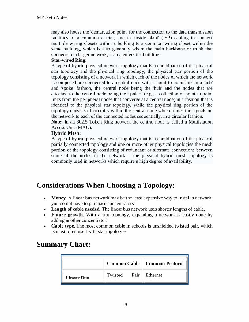
MYcsvtu Notes
29
may also house the demarcation point for the connection to the data transmission
facilities of a common carrier and in inside plant (ISP) cabling to connect
multiple wiring closets within a building to a common wiring closet within the
same building which is also generally where the main backbone or trunk that
connects to a larger network if any enters the building
Star-wired Ring A type of hybrid physical network topology that is a combination of the physical
star topology and the physical ring topology the physical star portion of the
topology consisting of a network in which each of the nodes of which the network
is composed are connected to a central node with a point-to-point link in a hub
and spoke fashion the central node being the hub and the nodes that are
attached to the central node being the spokes (eg a collection of point-to-point
links from the peripheral nodes that converge at a central node) in a fashion that is
identical to the physical star topology while the physical ring portion of the
topology consists of circuitry within the central node which routes the signals on
the network to each of the connected nodes sequentially in a circular fashion
Note In an 8025 Token Ring network the central node is called a Multistation
Access Unit (MAU)
Hybrid Mesh A type of hybrid physical network topology that is a combination of the physical
partially connected topology and one or more other physical topologies the mesh
portion of the topology consisting of redundant or alternate connections between
some of the nodes in the network ndash the physical hybrid mesh topology is
commonly used in networks which require a high degree of availability
Considerations When Choosing a Topology
Money A linear bus network may be the least expensive way to install a network
you do not have to purchase concentrators
Length of cable needed The linear bus network uses shorter lengths of cable
Future growth With a star topology expanding a network is easily done by
adding another concentrator
Cable type The most common cable in schools is unshielded twisted pair which
is most often used with star topologies
Summary Chart
Common Cable Common Protocol
Linear Bus Twisted Pair
Coaxial
Ethernet
LocalTalk
MYcsvtu Notes
30
Fiber
Star Twisted Pair
Fiber
Ethernet
LocalTalk
Star-Wired Ring Twisted Pair Token Ring
Tree
Twisted Pair
Coaxial
Fiber
Ethernet
Internet vs Web
The Internet and the World Wide Web are not synonymous the Internet is a collection of
interconnected computer networks linked by copper wires fiber-optic cables wireless
connections etc the Web is a collection of interconnected documents and other
resources linked by hyperlinks and URLs The World Wide Web is accessible via the
Internet as are many other services including e-mail file sharing and others described
below
The best way to define and distinguish between these terms is to understand the Internet
protocol suite This collection of protocols is organized into layers such that each layer
provides the foundation and the services required by the layer above In this conception
the term Internet refers to computer networks that all communicate with IP (Internet
protocol) and TCP (transfer control protocol) Once this networking structure is
established then other protocols can run ―on top These other protocols are sometimes
called services or applications Hypertext transfer protocol or HTTP is an application
layer protocol that links billions of files together into the World Wide Web
Common uses of the Internet
The World Wide Web
Through keyword-driven Internet research using search engines like Google
millions worldwide have easy instant access to a vast and diverse amount of
online information Compared to encyclopedias and traditional libraries the
World Wide Web has enabled a sudden and extreme decentralization of
information and data
Many individuals and some companies and groups have adopted the use of Web logs or
blogs which are largely used as easily-updatable online diaries Some commercial
organizations encourage staff to fill them with advice on their areas of specialization in
the hope that visitors will be impressed by the expert knowledge and free information
and be attracted to the corporation as a result One example of this practice is Microsoft
MYcsvtu Notes
31
whose product developers publish their personal blogs in order to pique the publics
interest in their work
For more information on the distinction between the World Wide Web and the Internet
itself mdash as in everyday use the two are sometimes confused mdash see Dark internet where
this is discussed in more detail
Remote access
The Internet allows computer users to connect to other computers and information stores
easily wherever they may be across the world They may do this with or without the use
of security authentication and encryption technologies depending on the requirements
This is encouraging new ways of working from home collaboration and information
sharing in many industries An accountant sitting at home can audit the books of a
company based in another country on a server situated in a third country that is remotely
maintained by IT specialists in a fourth These accounts could have been created by
home-working book-keepers in other remote locations based on information e-mailed to
them from offices all over the world Some of these things were possible before the
widespread use of the Internet but the cost of private leased lines would have made
many of them infeasible in practice
An office worker away from his desk perhaps the other side of the world on a business
trip or a holiday can open a remote desktop session into his normal office PC using a
secure Virtual Private Network (VPN) connection via the Internet This gives him
complete access to all his normal files and data including e-mail and other applications
while he is away
This concept is also referred to by some network security people as the Virtual Private
Nightmare because it extends the secure perimeter of a corporate network into its
employees homes this has been the source of some notable security breaches but also
provides security for the workers
Functions
File-sharing
Instant messaging
Internet fax
Search engine
World Wide Web
MYcsvtu Notes
32
Intranets
What are Intranets
bull Intranet is Intra+ Net so an Intranet is an internal or private Internet used strictly
within the confines of a company university or organization Inter means
between or among hence the difference between the Internet and an Intranet
Some formal definitions of Intranets
bull Brown amp Duguid ―Intranets help present and
circulate boundary objects
bull Choo Detlor amp Turnbull ―Intranetshellip support the creation sharing and use of
knowledge
bull Stenmark ―Intranets are organizationally
restricted
A technical definition
bull An Intranet is a network based on the internet TCPIP open standard An intranet
belongs to an organization and is designed to be accessible only by the
organizations members employees or others with authorization An intranets
Web site looks and act just like other Web sites but has a firewall surrounding it
to fend off unauthorized users
Design Of Intranets
Steps
bull Analyze the organizationlsquos information ecology
bull Identify the typical problems experienced by users
bull Analyze the information behaviors of these set of users
bull Create value added processes to resolve the problems of users and to improve the
Information Ecology
Value Added Processes
bull Intranets may be designed to improve the organizational information ecology
MYcsvtu Notes
33
bull Intranets provide a unified information space in which users can communicate
and collaborate with others
bull intranet applications and services may add value by supporting the organizationlsquos
knowledge creating and decision making process
Two Models of Online Environments
Centralized
Distributed
Centralized Environments
bull Before the web the centralized model was all we had (examples include
CompuServe Prodigy)
bull On the web centralized models include site-based services such as Yahoo
bull Most (all) college and university services are offered using the centralized
model
MYcsvtu Notes
34
bull But centralized environments are static inflexible expensive
Distributed Environments
bull The World Wide Web is an example of a distributed environment
bull Resources access are not centralized but scattered around the world
ndash Resources in the form of a network of connected (via DNS) web servers
ndash Access in the form of a network of connected (via DNS) internet service
providers
ndash Users in the form of individualized and connected (via HTTP) web
browsers
bull The big issue ndash integration ndash that is making different systems work together
Design Principles
Network Design Principles
ndash Specifies how networks differ from traditional learning
ndash The idea is that each principle confers an advantage over non-network
systems
ndash Can be used as a means of evaluating new technology
1 Decentralize
ndash Centralized networks have a characteristic starlsquo shape
bull Some entities have many connections
bull The vast majority have few
bull Eg broadcast network teacher in a classroom
ndash Decentralized networks form a mesh
bull The weight of connections flow is distributed
bull Balanced load = more stable
bull Foster connections between entities fill outlsquo the star
Distribute
ndash Network entities reside in different physical locations
bull Reduces risk of network failure
bull Reduces need for major infrastructure such as powerful servers
large bandwidth massive storage
ndash Examples
bull Peer-to-peer networks such as Kazaa Gnutella
bull Content syndication networks such as RSS
ndash Emphasis is on sharing not copying
bull Locallsquo copies are temporary
MYcsvtu Notes
35
Computer Graphics
Computer Graphics is about animation (films)
Games are very important in Computer Graphics
Medical Imaging is another driving force
Computer Aided Design too
Graphics Definitions
bull Point
ndash a location in space 2D or 3D
ndash sometimes denotes one pixel
bull Line
ndash straight path connecting two points
ndash infinitesimal width consistent density
ndash beginning and end on points
bull Vertex
ndash point in 3D
bull Edge
ndash line in 3D connecting two vertices
bull PolygonFaceFacet
ndash arbitrary shape formed by connected vertices
ndash fundamental unit of 3D computer graphics
bull Raster
ndash derived from TV systems for a row of pixels
ndash commonly referred to as a scanline
ndash does influence algorithms ndash reducing memory requirements parallelism
etc
ndash is the derivation of rasterization scan-line algorithms
Displays
bull Most desktop displays use a cathode ray tube (CRT) while portable computing
devices such as laptops incorporate liquid crystal display (LCD)
bull Because of their slimmer design and smaller energy consumption monitors using
LCD technologies are beginning to replace the venerable CRT on many desktops
Cathode-Ray Tubes
MYcsvtu Notes
36
bull Classical output device is a monitor
bull Cathode-Ray Tube (CRT)
ndash Invented by Karl Ferdinand Braun (1897)
ndash Beam of electrons directed from cathode (-)to phosphor-coated
(fluorescent) screen (anode (+))
ndash Directed by magnetic focusing and deflection coils (anodes) in vacuum
filled tube
ndash Phosphor emits photon of light when hit by an electron of varied
persistence (long 15-20 ms for texts short lt 1ms for animation)
ndash Refresh rate (50-60 Hz 72-76 Hz) to avoid flicker trail
ndash Phosphors are organic compounds characterized by their persistence and
their color (blue red green)
Cathode-Ray Tubes
bull Cathode-Ray Tube (CRT)
ndash Horizontal deflection and vertical deflection direct the electron beam to
any point on the screen
ndash Intensity knob regulates the flow of electrons by controlling the voltage at
the control grid (high voltage reduces the electron density and thus
brightness)
ndash Accelerating voltage from positive coating inside screen (anode screen) or
an accelerating anode
bull Image maintenance
ndash Charge distribution to store picture information
OR
ndash Refresh CRT refreshes the display constantly to maintain phosphor glow
Cathode-Ray Tubes
bullCathode-Ray Tube (CRT)
ndash Horizontal deflection and vertical deflection direct the electron beam to any point
on the screen
ndash Intensity knob regulates the flow of electrons by controlling the voltage at the
control grid (high voltage reduces the electron density and thus brightness)
ndash Accelerating voltage from positive coating inside screen (anode screen) or an
accelerating anode
bullImage maintenance
ndash Charge distribution to store picture information
OR
ndash Refresh CRT refreshes the display constantly to maintain phosphor glow
bull Characteristics of Cathode-Ray Tube (CRT)
MYcsvtu Notes
37
ndash Intensity is proportional to the number of electrons repelled in beam per
second (brightness)
ndash Resolution is the maximum number of points that can be displayed
without overlap is expressed as number of horizontal points by number of
vertical points points are called pixels (picture elements) example
resolution 1024 x 768 pixels Typical resolution is 1280 x 1024 pixels
bull High-definition systems high resolution systems
bull Focusing
ndash Focusing forces the electron beam to converge to a point on the monitor
screen
ndash Can be electrostatic (lens) or magnetic (field)
bull Deflection
ndash Deflection directs the electron beam horizontally andor vertically to any
point on the screen
ndash Can be controlled by electric (deflection plates slide 9) or magnetic fields
(deflection coils slide 5)
ndash Magnetic coils two pairs (topbottom leftright) of tube neck
ndash Electric plates two pairs (horizontal vertical)
Raster-scan Displays
bullVideo displays can be either raster-scan or random-scan displays
bullRaster-scan display is the most common type of monitor using a CRT
bullThe electron beam scans the screen from top to bottom one row at a time Each row is
called a scan line
bullThe electron beam is turned on and off to produce a collection of dots painted one row at
a time These will form the image
bullA raster is a matrix of pixels covering the screen area and is composed of raster lines
Raster-scan Displays
MYcsvtu Notes
38
Raster-scan Displays
bullThe image is stored in a frame buffer containing the total screen area and where each
memory location corresponds to a pixel
bullIn a monochrome system each bit is 1 or 0 for the corresponding pixel to be on or off
(bitmap)
bullThe display processor scans the frame buffer to turn electron beam onoff depending if
the bit is 1 or 0
bullFor color monitors the frame buffer also contains the color of each pixel (color buffer)
as well as other characteristics of the image (gray scale hellip) 8 bitspixel 0255
(pixmap)
bullDepth of the buffer area is the number of bits per pixel (bit planes) up to 24
bullExamples television panels printers PC monitors (99 of raster-scan)
Raster-scan Displays
bullRefresh rate 24 is a minimum to avoid flicker corresponding to 24 Hz (1 Hz = 1 refresh
per second)
bullCurrent raster-scan displays have a refresh rate of at least 60 frames (60 Hz) per second
up to 120 (120 Hz)
bullUses large memory 640x480 307200 bits 38 kB
bullRefresh procedure
MYcsvtu Notes
39
ndashHorizontal retrace ndash beam returns to left of screen
ndashVertical retrace ndash bean returns to top left corner of screen
ndashInterlaced refresh ndash display first even-numbered lines then odd-numbered lines
permits to see the image in half the time
useful for slow refresh rates (30 Hz shows as 60 Hz)
Random-scan Displays
bullRandom scan systems are also called vector stroke-writing or calligraphic displays
bullThe electron beam directly draws the picture in any specified order
bullA pen plotter is an example of such a system
bullPicture is stored in a display list refresh display file vector file or display program as a
set of line drawing commands
bullRefreshes by scanning the list 30 to 60 times per second
bullMore suited for line-drawing applications such as architecture and manufacturing
Random-scan Displays
bullAdvantages
ndashHigh resolution
ndashEasy animation
ndashRequires little memory
bullDisadvantages
ndashRequires intelligent electron beam (processor controlled)
ndashLimited screen density limited to simple line-based images
ndashLimited color capability
bullImproved in the 1960lsquos by the Direct View Storage Tube (DVST) from Tektronix
Color CRT Monitor
Uses different phosphors a combination of Red Green and Blue to produce any color
Two methods
Random scan uses beam penetration
2 layers (Red Green) phosphors low speed electrons excite Red high speed electrons
excite Green interrmediate speed excite both to get yellow and orange Color is
controlled by electron beam voltage
Only produces a restricted set of colors
Raster scan uses a shadow mask with three electron guns Red Green and Blue (RGB
color model) Color is produced by adjusting the intensity level of each electron beam
Produces a wide range of colors from 8 to several millions
Raster scan
Most common as found in televisions
Beam scanned left to right flicked back to rescan from top to bottom then repeated
Repeated at 30Hz per frame sometimes higher to reduce flicker Interlacing scanning
MYcsvtu Notes
40
odd lines in whole screen then even lines is also used to reduce flicker Can also use
high-persistence phosphor to reduce flicker but causes image smearing especially with
significant animation
Resolution typically 512x512 but high-quality screens are available (and becoming more
common) at up to approximately 1600x1200 pixels Sun workstations have screens of
1192x980 pixels
Black amp white screens can display grayscale by varying the intensity of the electron
beam
Colour is achieved using three electron guns which hit red green or blue phosphors
Combining these colours can produce many others including white (all on) Phosphor
dots focused using a shadow mask - makes colour screens lower resolution than
monochrome
Alternative approach beam penetration Special phosphor glows a different colour
depending on intensity of beam
Colour or intensity at pixel held by computerlsquos video card 1 bitpixel can store offon
information hence only black ampwhite More bitspixel give rise to more colour
possibilities eg 8 bitspixel gives rise to 2^8=256 possible colours at any one time
Random Scan (Directed-beam refresh vector display)
Instead of scanning the whole display sequentially and horizontally the random scan
draws the lines to be displayed directly Screen update at gt30Hz to reduce flicker
Jaggies not found and higher resolutions possible (up to 4096x4096 pixels) Colour
achieved using beam penetration generally of poorer quality Eye strain and fatigue still
a problem and vector displays are more expensive
Direct view storage tube (DVST)
Used a lot in analogue storage oscilloscopes
Similar to random scan crt but image maintained by flood guns - no flicker Can be
incrementally updated but not selectively erased image has to be redrawn on completely
erased screen High resolution (typically 4096x3120 pixels) but low contrast low
brightness and difficulty in displaying colour
What is a Multimedia System
bull A system that involves
ndash generation
ndash representation
ndash storage
ndash transmission
ndash search and retrieval
ndash delivery
MYcsvtu Notes
41
of multimedia information
productionauthoring tools
compression and formats
file system design
networking issues
database management
server design streaming
Multimedia System Architecture
Information management subsystem Presentation Query
Storage subsystem Efficiently stored
amp retrieved
Network subsystem Delivery
Adaptation in Multimedia Systems
bull Multimedia systems can profit a lot from personalization
ndash User behavior
ndash User properties
bull Adaptation
ndash Models
ndash Mechanisms
Multimedia in a mobile environment
MYcsvtu Notes
42
bull Applications
ndash Emergency response systems mobile commerce phone service
entertainment games
What is Sound
A ripple is a pressure wave in water created by an object striking the water
Sound is a pressure wave in air created for example by an object such as a string
or our vocal cords vibrating Dark here represents more pressure light represents
less
MYcsvtu Notes
43
Sine Waves Form Pure Tones
This simple sound wave is a Sine Wave a Pure tone produced by a simple vibration
Sine Wave Sample Tone
This can be represented graphically as shown above
Converting Pressure into Voltage
The pressure wave of sound moves a diaphragm in the microphone which produces a
voltage proportional to the pressure of the sound wave at each instant
Animation
MYcsvtu Notes
44
bull Animation is the rapid display of a sequence of images of 2-D artwork or model
positions in order to create an illusion of movement It is an optical illusion of
motion due to the phenomenon of persistence of vision This could be anything
from a flip book to a motion picture film Animation deals with the generation
sequencing and display a set of images which is called frames to create an effect
of visual change or motion similar to a movie film
bull Animation is used in those instance where videography is not possible
Hardware Requirement For Animation
bull Image Generation Tools amp Devices
bull Computer monitors with image display Capability
Software Requirement For Animation
bull Animation creating software
bull Screen Capture Software
bull Animation Clips
bull Software support For High Resolution
bull Recording amp Playback Capability
bull Transition effect
Early animation
There is no single person that can be considered the creator of the art of animation as
there were several people doing several projects which could be considered various types
of animation all around the same time (Short hand-drawn animation scenes could be
presented with the Phenakistoscope the Zoetrope and other optical toys already in the
early 1800s)
The following is a brief listing on those who are often acknowledged as significant to the
development of animation Note that this list is by no means a comprehensive list of
contributors to early animation
Georges Meacuteliegraves was a creator of special effect films such as A Trip to the Moon He
used many techniques ndash one of which was to stop the camera rolling change something
in the scene and then continue rolling the film This is a very similar idea to that of stop-
motion animation Meacuteliegraves accidentally happened upon the technique when his camera
broke down while shooting a bus driving by When the camera was fixed a horse
happened to be passing by just as Meacuteliegraves continued to film The result was that the bus
appeared to change into a horse
MYcsvtu Notes
45
Fantasmagorie by Emile Cohl 1908
Eacutemile Cohl began drawing cartoon strips and created a film in 1908 called
Fantasmagorie The film largely consisted of a stick figure moving about and
encountering all manner of morphing objects such as a wine bottle that transforms into a
flower There were also sections of live action where the animatorlsquos hands would enter
the scene The film was created by drawing each frame on paper and then shooting each
frame onto negative film which gave the picture a blackboard look
Winsor McCay created detailed animations that required a team of artists and painstaking
attention for detail Each frame was drawn on paper requiring backgrounds to be
redrawn as well characters to be animated His films such as Gertie the Dinosaur (1914)
and The Sinking of the Lusitania (1918) were of an impressive scale although The
Sinking of the Lusitania used cels
In 1919 Otto Messmer created the character of Felix the cat for Pat Sullivans animation
studios The importance of Felix lies in the characters strong personality created largely
through gesture and actions
Animation techniques
Animation techniques are incredibly varied and difficult to categorize Techniques are
often related or combined The following is a brief on common types of animation
Again this list is by no means comprehensive
Traditional animation
An example of traditional animation a horse animated by rotoscoping from Edweard
Muybridges 19th century photos
Main article Traditional animation
MYcsvtu Notes
46
Also called cel animation the frames of a traditionally animated movie are hand-drawn
The drawings are traced or copied onto transparent acetate sheets called cels which are
then placed over a painted background and photographed one by one on a rostrum
camera Nowadays the use of cels (and cameras) is mostly obsolete since the drawings
are scanned into computers and digitally transferred directly to 35 mm film The look
of traditional cel animation is still preserved and the character animators work has
remained essentially the same over the past 70 years Because of the digital influence
over modern cel animation it is also known as tradigital animation
Examples The Lion King Spirited Away Les Triplettes de Belleville
Full animation The most common style in animation known for its realistic and often very detailed art
Examples All Disney feature length animated films The Secret of NIMH The Iron Giant
Limited animation A cheaper process of making animated cartoons that does not follow a realistic
approach
Examples The Flintstones Yellow Submarine
Rubber hose The characters are usually cartoony and the animators have a lot of artistic freedom as
rubber hose animations dont have to follow the laws of physics and anatomy in the same
degree as the other main styles in animation
Examples Early Mickey Mouse cartoons Ren and Stimpy Popeye
Rotoscoping A technique where animators trace live action movement frame by frame for use in
animated films
Examples Gullivers Travels American Pop
Stop motion
Stop-motion animation is any type of animation which requires the animator to physically
alter the scene shoot a frame again alter the scene and shoot a frame and so on to create
the animation There are many different types of stop-motion animation some noteable
examples are listed below
Clay animation
MYcsvtu Notes
47
A clay animation scene from a TV commercial
Often abbreviated to claymation this is a type of stop-motion animation using
figures made of clay or a similar malleable material The figures may have an
armature or wire frame inside of them similar to puppet animation (below)
Alternatively the figures may be made entirely of clay such as in the films of
Bruce Bickford where clay creatures morph into a variety of different shapes
Examples Wallace and Gromit Dimensions of Dialogue by Jan Švankmajer The
Amazing Mr Bickford The Trap Door
Cutout animation In this type of stop-motion animation the animation is formed by moving 2-
dimensional pieces of material such as paper or cloth
Examples the animated sequences of Monty Pythons Flying Circus (often
referred to as Dada animation named after the Dada art movement[citation needed]
)
Tale of Tales early episodes of South Park
Silhouette animation A type of cutout animation where the viewer only sees black silhouettes
Example The Adventures of Prince Achmed the worlds oldest surviving
animated feature film from 1926
Graphic animation
Model animation In this form of animation model animated characters interact with and are a part
of the live-action world
Examples The films of Ray Harryhausen (Jason and the Argonauts) and Willis
OBrien (King Kong)
Go motion
Object animation
Pixilation Examples Neighbours
Puppet animation Puppet animation typically involves puppet figures interacting with each other in
a constructed environment in contrast to the real-world interaction in model
MYcsvtu Notes
48
animation (above) The puppets generally have an armature inside of them to
keep them still and steady as well as constraining them to move at particular
joints
Examples The Nightmare Before Christmas Robot Chicken The Tale of the Fox
Brickfilm
Puppetoon
Computer animation
A short gif animation
Like stop motion computer animation encompasses a variety of techniques the unifying
idea being that the animation is created digitally on a computer
2D animation Figures are created andor edited on the computer using 2D bitmap graphics or
created and edited using 2D vector graphics This includes automated
computerized versions of traditional animation techniques such as of tweening
morphing onion skinning and interpolated rotoscoping
Examples A Scanner Darkly Jib Jab
Analog computer animation
Flash animation
PowerPoint animation
A completely synthetic computer-generated scene
3D animation
MYcsvtu Notes
49
Figures are created in the computer using polygons To allow these meshes to
move they are given a digital armature (sculpture) This process is called rigging
Various other techniques can be applied such as mathematical functions
(gravity) simulated fur or hair effects such as fire and water and the use of
motion capture to name but a few
Examples The Incredibles Shrek
Cel-shaded animation
Morph target animation
Skeletal animation
Motion capture
Crowd simulation
Less common techniques
Drawn on film animation A technique where footage is produced by creating the
images directly on film stock
Paint-on-glass animationA technique for making animated films by manipulating slow-
drying oil paints on sheets of glass
Pinscreen animation Makes use of a screen filled with movable pins which can be
moved in or out by pressing an object onto the screen The screen is lit from the side so
that the pins cast shadows The technique has been used to create animated films with a
range of textural effects difficult to achieve with traditional cel animation
Sand animation Sand is moved around on a backlighted or frontlighted piece of glass to
create each frame for an animated film
Multimedia
Multimedia (Lat Multum + Medium) is media that uses multiple forms of information
content and information processing (eg text audio graphics animation video
interactivity) to inform or entertain the (user) audience Multimedia also refers to the use
of (but not limited to) electronic media to store and experience multimedia content
Multimedia is similar to traditional mixed media in fine art but with a broader scope The
term rich media is synonymous for interactive multimedia
Categorization
Multimedia may be broadly divided into linear and non-linear categories Linear active
content progresses without any navigation control for the viewer such as a cinema
presentation Non-linear content offers user interactivity to control progress as used with
MYcsvtu Notes
50
a computer game or used in self-paced computer based training Non-linear content is
also known as hypermedia content
Multimedia presentations can be live or recorded A recorded presentation may allow
interactivity via a navigation system A live multimedia presentation may allow
interactivity via interaction with the presenter or performer
There are 2 basic way to represent some information
Unimedium Presentation
Multimedia Presentation
In case of computer system the commonly used medioa for the purpose of storage
access and transmission of information are
bull Text
bull Graphics
bull Animation
bull Audio
bull Video
Multimedia Computer System require
bull Faster CPU
bull Larger Storage Devices
bull Larger Main Memory
bull Good Graphics Terminal
bull IO devices required to play an audio associated with the program
Transmission Mode
bull Asynchronous
bull Synchronous
bull Isochronous
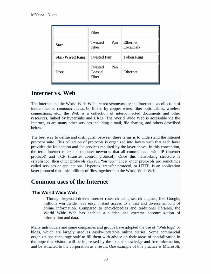
MYcsvtu Notes
30
Fiber
Star Twisted Pair
Fiber
Ethernet
LocalTalk
Star-Wired Ring Twisted Pair Token Ring
Tree
Twisted Pair
Coaxial
Fiber
Ethernet
Internet vs Web
The Internet and the World Wide Web are not synonymous the Internet is a collection of
interconnected computer networks linked by copper wires fiber-optic cables wireless
connections etc the Web is a collection of interconnected documents and other
resources linked by hyperlinks and URLs The World Wide Web is accessible via the
Internet as are many other services including e-mail file sharing and others described
below
The best way to define and distinguish between these terms is to understand the Internet
protocol suite This collection of protocols is organized into layers such that each layer
provides the foundation and the services required by the layer above In this conception
the term Internet refers to computer networks that all communicate with IP (Internet
protocol) and TCP (transfer control protocol) Once this networking structure is
established then other protocols can run ―on top These other protocols are sometimes
called services or applications Hypertext transfer protocol or HTTP is an application
layer protocol that links billions of files together into the World Wide Web
Common uses of the Internet
The World Wide Web
Through keyword-driven Internet research using search engines like Google
millions worldwide have easy instant access to a vast and diverse amount of
online information Compared to encyclopedias and traditional libraries the
World Wide Web has enabled a sudden and extreme decentralization of
information and data
Many individuals and some companies and groups have adopted the use of Web logs or
blogs which are largely used as easily-updatable online diaries Some commercial
organizations encourage staff to fill them with advice on their areas of specialization in
the hope that visitors will be impressed by the expert knowledge and free information
and be attracted to the corporation as a result One example of this practice is Microsoft
MYcsvtu Notes
31
whose product developers publish their personal blogs in order to pique the publics
interest in their work
For more information on the distinction between the World Wide Web and the Internet
itself mdash as in everyday use the two are sometimes confused mdash see Dark internet where
this is discussed in more detail
Remote access
The Internet allows computer users to connect to other computers and information stores
easily wherever they may be across the world They may do this with or without the use
of security authentication and encryption technologies depending on the requirements
This is encouraging new ways of working from home collaboration and information
sharing in many industries An accountant sitting at home can audit the books of a
company based in another country on a server situated in a third country that is remotely
maintained by IT specialists in a fourth These accounts could have been created by
home-working book-keepers in other remote locations based on information e-mailed to
them from offices all over the world Some of these things were possible before the
widespread use of the Internet but the cost of private leased lines would have made
many of them infeasible in practice
An office worker away from his desk perhaps the other side of the world on a business
trip or a holiday can open a remote desktop session into his normal office PC using a
secure Virtual Private Network (VPN) connection via the Internet This gives him
complete access to all his normal files and data including e-mail and other applications
while he is away
This concept is also referred to by some network security people as the Virtual Private
Nightmare because it extends the secure perimeter of a corporate network into its
employees homes this has been the source of some notable security breaches but also
provides security for the workers
Functions
File-sharing
Instant messaging
Internet fax
Search engine
World Wide Web
MYcsvtu Notes
32
Intranets
What are Intranets
bull Intranet is Intra+ Net so an Intranet is an internal or private Internet used strictly
within the confines of a company university or organization Inter means
between or among hence the difference between the Internet and an Intranet
Some formal definitions of Intranets
bull Brown amp Duguid ―Intranets help present and
circulate boundary objects
bull Choo Detlor amp Turnbull ―Intranetshellip support the creation sharing and use of
knowledge
bull Stenmark ―Intranets are organizationally
restricted
A technical definition
bull An Intranet is a network based on the internet TCPIP open standard An intranet
belongs to an organization and is designed to be accessible only by the
organizations members employees or others with authorization An intranets
Web site looks and act just like other Web sites but has a firewall surrounding it
to fend off unauthorized users
Design Of Intranets
Steps
bull Analyze the organizationlsquos information ecology
bull Identify the typical problems experienced by users
bull Analyze the information behaviors of these set of users
bull Create value added processes to resolve the problems of users and to improve the
Information Ecology
Value Added Processes
bull Intranets may be designed to improve the organizational information ecology
MYcsvtu Notes
33
bull Intranets provide a unified information space in which users can communicate
and collaborate with others
bull intranet applications and services may add value by supporting the organizationlsquos
knowledge creating and decision making process
Two Models of Online Environments
Centralized
Distributed
Centralized Environments
bull Before the web the centralized model was all we had (examples include
CompuServe Prodigy)
bull On the web centralized models include site-based services such as Yahoo
bull Most (all) college and university services are offered using the centralized
model
MYcsvtu Notes
34
bull But centralized environments are static inflexible expensive
Distributed Environments
bull The World Wide Web is an example of a distributed environment
bull Resources access are not centralized but scattered around the world
ndash Resources in the form of a network of connected (via DNS) web servers
ndash Access in the form of a network of connected (via DNS) internet service
providers
ndash Users in the form of individualized and connected (via HTTP) web
browsers
bull The big issue ndash integration ndash that is making different systems work together
Design Principles
Network Design Principles
ndash Specifies how networks differ from traditional learning
ndash The idea is that each principle confers an advantage over non-network
systems
ndash Can be used as a means of evaluating new technology
1 Decentralize
ndash Centralized networks have a characteristic starlsquo shape
bull Some entities have many connections
bull The vast majority have few
bull Eg broadcast network teacher in a classroom
ndash Decentralized networks form a mesh
bull The weight of connections flow is distributed
bull Balanced load = more stable
bull Foster connections between entities fill outlsquo the star
Distribute
ndash Network entities reside in different physical locations
bull Reduces risk of network failure
bull Reduces need for major infrastructure such as powerful servers
large bandwidth massive storage
ndash Examples
bull Peer-to-peer networks such as Kazaa Gnutella
bull Content syndication networks such as RSS
ndash Emphasis is on sharing not copying
bull Locallsquo copies are temporary
MYcsvtu Notes
35
Computer Graphics
Computer Graphics is about animation (films)
Games are very important in Computer Graphics
Medical Imaging is another driving force
Computer Aided Design too
Graphics Definitions
bull Point
ndash a location in space 2D or 3D
ndash sometimes denotes one pixel
bull Line
ndash straight path connecting two points
ndash infinitesimal width consistent density
ndash beginning and end on points
bull Vertex
ndash point in 3D
bull Edge
ndash line in 3D connecting two vertices
bull PolygonFaceFacet
ndash arbitrary shape formed by connected vertices
ndash fundamental unit of 3D computer graphics
bull Raster
ndash derived from TV systems for a row of pixels
ndash commonly referred to as a scanline
ndash does influence algorithms ndash reducing memory requirements parallelism
etc
ndash is the derivation of rasterization scan-line algorithms
Displays
bull Most desktop displays use a cathode ray tube (CRT) while portable computing
devices such as laptops incorporate liquid crystal display (LCD)
bull Because of their slimmer design and smaller energy consumption monitors using
LCD technologies are beginning to replace the venerable CRT on many desktops
Cathode-Ray Tubes
MYcsvtu Notes
36
bull Classical output device is a monitor
bull Cathode-Ray Tube (CRT)
ndash Invented by Karl Ferdinand Braun (1897)
ndash Beam of electrons directed from cathode (-)to phosphor-coated
(fluorescent) screen (anode (+))
ndash Directed by magnetic focusing and deflection coils (anodes) in vacuum
filled tube
ndash Phosphor emits photon of light when hit by an electron of varied
persistence (long 15-20 ms for texts short lt 1ms for animation)
ndash Refresh rate (50-60 Hz 72-76 Hz) to avoid flicker trail
ndash Phosphors are organic compounds characterized by their persistence and
their color (blue red green)
Cathode-Ray Tubes
bull Cathode-Ray Tube (CRT)
ndash Horizontal deflection and vertical deflection direct the electron beam to
any point on the screen
ndash Intensity knob regulates the flow of electrons by controlling the voltage at
the control grid (high voltage reduces the electron density and thus
brightness)
ndash Accelerating voltage from positive coating inside screen (anode screen) or
an accelerating anode
bull Image maintenance
ndash Charge distribution to store picture information
OR
ndash Refresh CRT refreshes the display constantly to maintain phosphor glow
Cathode-Ray Tubes
bullCathode-Ray Tube (CRT)
ndash Horizontal deflection and vertical deflection direct the electron beam to any point
on the screen
ndash Intensity knob regulates the flow of electrons by controlling the voltage at the
control grid (high voltage reduces the electron density and thus brightness)
ndash Accelerating voltage from positive coating inside screen (anode screen) or an
accelerating anode
bullImage maintenance
ndash Charge distribution to store picture information
OR
ndash Refresh CRT refreshes the display constantly to maintain phosphor glow
bull Characteristics of Cathode-Ray Tube (CRT)
MYcsvtu Notes
37
ndash Intensity is proportional to the number of electrons repelled in beam per
second (brightness)
ndash Resolution is the maximum number of points that can be displayed
without overlap is expressed as number of horizontal points by number of
vertical points points are called pixels (picture elements) example
resolution 1024 x 768 pixels Typical resolution is 1280 x 1024 pixels
bull High-definition systems high resolution systems
bull Focusing
ndash Focusing forces the electron beam to converge to a point on the monitor
screen
ndash Can be electrostatic (lens) or magnetic (field)
bull Deflection
ndash Deflection directs the electron beam horizontally andor vertically to any
point on the screen
ndash Can be controlled by electric (deflection plates slide 9) or magnetic fields
(deflection coils slide 5)
ndash Magnetic coils two pairs (topbottom leftright) of tube neck
ndash Electric plates two pairs (horizontal vertical)
Raster-scan Displays
bullVideo displays can be either raster-scan or random-scan displays
bullRaster-scan display is the most common type of monitor using a CRT
bullThe electron beam scans the screen from top to bottom one row at a time Each row is
called a scan line
bullThe electron beam is turned on and off to produce a collection of dots painted one row at
a time These will form the image
bullA raster is a matrix of pixels covering the screen area and is composed of raster lines
Raster-scan Displays
MYcsvtu Notes
38
Raster-scan Displays
bullThe image is stored in a frame buffer containing the total screen area and where each
memory location corresponds to a pixel
bullIn a monochrome system each bit is 1 or 0 for the corresponding pixel to be on or off
(bitmap)
bullThe display processor scans the frame buffer to turn electron beam onoff depending if
the bit is 1 or 0
bullFor color monitors the frame buffer also contains the color of each pixel (color buffer)
as well as other characteristics of the image (gray scale hellip) 8 bitspixel 0255
(pixmap)
bullDepth of the buffer area is the number of bits per pixel (bit planes) up to 24
bullExamples television panels printers PC monitors (99 of raster-scan)
Raster-scan Displays
bullRefresh rate 24 is a minimum to avoid flicker corresponding to 24 Hz (1 Hz = 1 refresh
per second)
bullCurrent raster-scan displays have a refresh rate of at least 60 frames (60 Hz) per second
up to 120 (120 Hz)
bullUses large memory 640x480 307200 bits 38 kB
bullRefresh procedure
MYcsvtu Notes
39
ndashHorizontal retrace ndash beam returns to left of screen
ndashVertical retrace ndash bean returns to top left corner of screen
ndashInterlaced refresh ndash display first even-numbered lines then odd-numbered lines
permits to see the image in half the time
useful for slow refresh rates (30 Hz shows as 60 Hz)
Random-scan Displays
bullRandom scan systems are also called vector stroke-writing or calligraphic displays
bullThe electron beam directly draws the picture in any specified order
bullA pen plotter is an example of such a system
bullPicture is stored in a display list refresh display file vector file or display program as a
set of line drawing commands
bullRefreshes by scanning the list 30 to 60 times per second
bullMore suited for line-drawing applications such as architecture and manufacturing
Random-scan Displays
bullAdvantages
ndashHigh resolution
ndashEasy animation
ndashRequires little memory
bullDisadvantages
ndashRequires intelligent electron beam (processor controlled)
ndashLimited screen density limited to simple line-based images
ndashLimited color capability
bullImproved in the 1960lsquos by the Direct View Storage Tube (DVST) from Tektronix
Color CRT Monitor
Uses different phosphors a combination of Red Green and Blue to produce any color
Two methods
Random scan uses beam penetration
2 layers (Red Green) phosphors low speed electrons excite Red high speed electrons
excite Green interrmediate speed excite both to get yellow and orange Color is
controlled by electron beam voltage
Only produces a restricted set of colors
Raster scan uses a shadow mask with three electron guns Red Green and Blue (RGB
color model) Color is produced by adjusting the intensity level of each electron beam
Produces a wide range of colors from 8 to several millions
Raster scan
Most common as found in televisions
Beam scanned left to right flicked back to rescan from top to bottom then repeated
Repeated at 30Hz per frame sometimes higher to reduce flicker Interlacing scanning
MYcsvtu Notes
40
odd lines in whole screen then even lines is also used to reduce flicker Can also use
high-persistence phosphor to reduce flicker but causes image smearing especially with
significant animation
Resolution typically 512x512 but high-quality screens are available (and becoming more
common) at up to approximately 1600x1200 pixels Sun workstations have screens of
1192x980 pixels
Black amp white screens can display grayscale by varying the intensity of the electron
beam
Colour is achieved using three electron guns which hit red green or blue phosphors
Combining these colours can produce many others including white (all on) Phosphor
dots focused using a shadow mask - makes colour screens lower resolution than
monochrome
Alternative approach beam penetration Special phosphor glows a different colour
depending on intensity of beam
Colour or intensity at pixel held by computerlsquos video card 1 bitpixel can store offon
information hence only black ampwhite More bitspixel give rise to more colour
possibilities eg 8 bitspixel gives rise to 2^8=256 possible colours at any one time
Random Scan (Directed-beam refresh vector display)
Instead of scanning the whole display sequentially and horizontally the random scan
draws the lines to be displayed directly Screen update at gt30Hz to reduce flicker
Jaggies not found and higher resolutions possible (up to 4096x4096 pixels) Colour
achieved using beam penetration generally of poorer quality Eye strain and fatigue still
a problem and vector displays are more expensive
Direct view storage tube (DVST)
Used a lot in analogue storage oscilloscopes
Similar to random scan crt but image maintained by flood guns - no flicker Can be
incrementally updated but not selectively erased image has to be redrawn on completely
erased screen High resolution (typically 4096x3120 pixels) but low contrast low
brightness and difficulty in displaying colour
What is a Multimedia System
bull A system that involves
ndash generation
ndash representation
ndash storage
ndash transmission
ndash search and retrieval
ndash delivery
MYcsvtu Notes
41
of multimedia information
productionauthoring tools
compression and formats
file system design
networking issues
database management
server design streaming
Multimedia System Architecture
Information management subsystem Presentation Query
Storage subsystem Efficiently stored
amp retrieved
Network subsystem Delivery
Adaptation in Multimedia Systems
bull Multimedia systems can profit a lot from personalization
ndash User behavior
ndash User properties
bull Adaptation
ndash Models
ndash Mechanisms
Multimedia in a mobile environment
MYcsvtu Notes
42
bull Applications
ndash Emergency response systems mobile commerce phone service
entertainment games
What is Sound
A ripple is a pressure wave in water created by an object striking the water
Sound is a pressure wave in air created for example by an object such as a string
or our vocal cords vibrating Dark here represents more pressure light represents
less
MYcsvtu Notes
43
Sine Waves Form Pure Tones
This simple sound wave is a Sine Wave a Pure tone produced by a simple vibration
Sine Wave Sample Tone
This can be represented graphically as shown above
Converting Pressure into Voltage
The pressure wave of sound moves a diaphragm in the microphone which produces a
voltage proportional to the pressure of the sound wave at each instant
Animation
MYcsvtu Notes
44
bull Animation is the rapid display of a sequence of images of 2-D artwork or model
positions in order to create an illusion of movement It is an optical illusion of
motion due to the phenomenon of persistence of vision This could be anything
from a flip book to a motion picture film Animation deals with the generation
sequencing and display a set of images which is called frames to create an effect
of visual change or motion similar to a movie film
bull Animation is used in those instance where videography is not possible
Hardware Requirement For Animation
bull Image Generation Tools amp Devices
bull Computer monitors with image display Capability
Software Requirement For Animation
bull Animation creating software
bull Screen Capture Software
bull Animation Clips
bull Software support For High Resolution
bull Recording amp Playback Capability
bull Transition effect
Early animation
There is no single person that can be considered the creator of the art of animation as
there were several people doing several projects which could be considered various types
of animation all around the same time (Short hand-drawn animation scenes could be
presented with the Phenakistoscope the Zoetrope and other optical toys already in the
early 1800s)
The following is a brief listing on those who are often acknowledged as significant to the
development of animation Note that this list is by no means a comprehensive list of
contributors to early animation
Georges Meacuteliegraves was a creator of special effect films such as A Trip to the Moon He
used many techniques ndash one of which was to stop the camera rolling change something
in the scene and then continue rolling the film This is a very similar idea to that of stop-
motion animation Meacuteliegraves accidentally happened upon the technique when his camera
broke down while shooting a bus driving by When the camera was fixed a horse
happened to be passing by just as Meacuteliegraves continued to film The result was that the bus
appeared to change into a horse
MYcsvtu Notes
45
Fantasmagorie by Emile Cohl 1908
Eacutemile Cohl began drawing cartoon strips and created a film in 1908 called
Fantasmagorie The film largely consisted of a stick figure moving about and
encountering all manner of morphing objects such as a wine bottle that transforms into a
flower There were also sections of live action where the animatorlsquos hands would enter
the scene The film was created by drawing each frame on paper and then shooting each
frame onto negative film which gave the picture a blackboard look
Winsor McCay created detailed animations that required a team of artists and painstaking
attention for detail Each frame was drawn on paper requiring backgrounds to be
redrawn as well characters to be animated His films such as Gertie the Dinosaur (1914)
and The Sinking of the Lusitania (1918) were of an impressive scale although The
Sinking of the Lusitania used cels
In 1919 Otto Messmer created the character of Felix the cat for Pat Sullivans animation
studios The importance of Felix lies in the characters strong personality created largely
through gesture and actions
Animation techniques
Animation techniques are incredibly varied and difficult to categorize Techniques are
often related or combined The following is a brief on common types of animation
Again this list is by no means comprehensive
Traditional animation
An example of traditional animation a horse animated by rotoscoping from Edweard
Muybridges 19th century photos
Main article Traditional animation
MYcsvtu Notes
46
Also called cel animation the frames of a traditionally animated movie are hand-drawn
The drawings are traced or copied onto transparent acetate sheets called cels which are
then placed over a painted background and photographed one by one on a rostrum
camera Nowadays the use of cels (and cameras) is mostly obsolete since the drawings
are scanned into computers and digitally transferred directly to 35 mm film The look
of traditional cel animation is still preserved and the character animators work has
remained essentially the same over the past 70 years Because of the digital influence
over modern cel animation it is also known as tradigital animation
Examples The Lion King Spirited Away Les Triplettes de Belleville
Full animation The most common style in animation known for its realistic and often very detailed art
Examples All Disney feature length animated films The Secret of NIMH The Iron Giant
Limited animation A cheaper process of making animated cartoons that does not follow a realistic
approach
Examples The Flintstones Yellow Submarine
Rubber hose The characters are usually cartoony and the animators have a lot of artistic freedom as
rubber hose animations dont have to follow the laws of physics and anatomy in the same
degree as the other main styles in animation
Examples Early Mickey Mouse cartoons Ren and Stimpy Popeye
Rotoscoping A technique where animators trace live action movement frame by frame for use in
animated films
Examples Gullivers Travels American Pop
Stop motion
Stop-motion animation is any type of animation which requires the animator to physically
alter the scene shoot a frame again alter the scene and shoot a frame and so on to create
the animation There are many different types of stop-motion animation some noteable
examples are listed below
Clay animation
MYcsvtu Notes
47
A clay animation scene from a TV commercial
Often abbreviated to claymation this is a type of stop-motion animation using
figures made of clay or a similar malleable material The figures may have an
armature or wire frame inside of them similar to puppet animation (below)
Alternatively the figures may be made entirely of clay such as in the films of
Bruce Bickford where clay creatures morph into a variety of different shapes
Examples Wallace and Gromit Dimensions of Dialogue by Jan Švankmajer The
Amazing Mr Bickford The Trap Door
Cutout animation In this type of stop-motion animation the animation is formed by moving 2-
dimensional pieces of material such as paper or cloth
Examples the animated sequences of Monty Pythons Flying Circus (often
referred to as Dada animation named after the Dada art movement[citation needed]
)
Tale of Tales early episodes of South Park
Silhouette animation A type of cutout animation where the viewer only sees black silhouettes
Example The Adventures of Prince Achmed the worlds oldest surviving
animated feature film from 1926
Graphic animation
Model animation In this form of animation model animated characters interact with and are a part
of the live-action world
Examples The films of Ray Harryhausen (Jason and the Argonauts) and Willis
OBrien (King Kong)
Go motion
Object animation
Pixilation Examples Neighbours
Puppet animation Puppet animation typically involves puppet figures interacting with each other in
a constructed environment in contrast to the real-world interaction in model
MYcsvtu Notes
48
animation (above) The puppets generally have an armature inside of them to
keep them still and steady as well as constraining them to move at particular
joints
Examples The Nightmare Before Christmas Robot Chicken The Tale of the Fox
Brickfilm
Puppetoon
Computer animation
A short gif animation
Like stop motion computer animation encompasses a variety of techniques the unifying
idea being that the animation is created digitally on a computer
2D animation Figures are created andor edited on the computer using 2D bitmap graphics or
created and edited using 2D vector graphics This includes automated
computerized versions of traditional animation techniques such as of tweening
morphing onion skinning and interpolated rotoscoping
Examples A Scanner Darkly Jib Jab
Analog computer animation
Flash animation
PowerPoint animation
A completely synthetic computer-generated scene
3D animation
MYcsvtu Notes
49
Figures are created in the computer using polygons To allow these meshes to
move they are given a digital armature (sculpture) This process is called rigging
Various other techniques can be applied such as mathematical functions
(gravity) simulated fur or hair effects such as fire and water and the use of
motion capture to name but a few
Examples The Incredibles Shrek
Cel-shaded animation
Morph target animation
Skeletal animation
Motion capture
Crowd simulation
Less common techniques
Drawn on film animation A technique where footage is produced by creating the
images directly on film stock
Paint-on-glass animationA technique for making animated films by manipulating slow-
drying oil paints on sheets of glass
Pinscreen animation Makes use of a screen filled with movable pins which can be
moved in or out by pressing an object onto the screen The screen is lit from the side so
that the pins cast shadows The technique has been used to create animated films with a
range of textural effects difficult to achieve with traditional cel animation
Sand animation Sand is moved around on a backlighted or frontlighted piece of glass to
create each frame for an animated film
Multimedia
Multimedia (Lat Multum + Medium) is media that uses multiple forms of information
content and information processing (eg text audio graphics animation video
interactivity) to inform or entertain the (user) audience Multimedia also refers to the use
of (but not limited to) electronic media to store and experience multimedia content
Multimedia is similar to traditional mixed media in fine art but with a broader scope The
term rich media is synonymous for interactive multimedia
Categorization
Multimedia may be broadly divided into linear and non-linear categories Linear active
content progresses without any navigation control for the viewer such as a cinema
presentation Non-linear content offers user interactivity to control progress as used with
MYcsvtu Notes
50
a computer game or used in self-paced computer based training Non-linear content is
also known as hypermedia content
Multimedia presentations can be live or recorded A recorded presentation may allow
interactivity via a navigation system A live multimedia presentation may allow
interactivity via interaction with the presenter or performer
There are 2 basic way to represent some information
Unimedium Presentation
Multimedia Presentation
In case of computer system the commonly used medioa for the purpose of storage
access and transmission of information are
bull Text
bull Graphics
bull Animation
bull Audio
bull Video
Multimedia Computer System require
bull Faster CPU
bull Larger Storage Devices
bull Larger Main Memory
bull Good Graphics Terminal
bull IO devices required to play an audio associated with the program
Transmission Mode
bull Asynchronous
bull Synchronous
bull Isochronous
MYcsvtu Notes
32
Intranets
What are Intranets
bull Intranet is Intra+ Net so an Intranet is an internal or private Internet used strictly
within the confines of a company university or organization Inter means
between or among hence the difference between the Internet and an Intranet
Some formal definitions of Intranets
bull Brown amp Duguid ―Intranets help present and
circulate boundary objects
bull Choo Detlor amp Turnbull ―Intranetshellip support the creation sharing and use of
knowledge
bull Stenmark ―Intranets are organizationally
restricted
A technical definition
bull An Intranet is a network based on the internet TCPIP open standard An intranet
belongs to an organization and is designed to be accessible only by the
organizations members employees or others with authorization An intranets
Web site looks and act just like other Web sites but has a firewall surrounding it
to fend off unauthorized users
Design Of Intranets
Steps
bull Analyze the organizationlsquos information ecology
bull Identify the typical problems experienced by users
bull Analyze the information behaviors of these set of users
bull Create value added processes to resolve the problems of users and to improve the
Information Ecology
Value Added Processes
bull Intranets may be designed to improve the organizational information ecology
MYcsvtu Notes
33
bull Intranets provide a unified information space in which users can communicate
and collaborate with others
bull intranet applications and services may add value by supporting the organizationlsquos
knowledge creating and decision making process
Two Models of Online Environments
Centralized
Distributed
Centralized Environments
bull Before the web the centralized model was all we had (examples include
CompuServe Prodigy)
bull On the web centralized models include site-based services such as Yahoo
bull Most (all) college and university services are offered using the centralized
model
MYcsvtu Notes
34
bull But centralized environments are static inflexible expensive
Distributed Environments
bull The World Wide Web is an example of a distributed environment
bull Resources access are not centralized but scattered around the world
ndash Resources in the form of a network of connected (via DNS) web servers
ndash Access in the form of a network of connected (via DNS) internet service
providers
ndash Users in the form of individualized and connected (via HTTP) web
browsers
bull The big issue ndash integration ndash that is making different systems work together
Design Principles
Network Design Principles
ndash Specifies how networks differ from traditional learning
ndash The idea is that each principle confers an advantage over non-network
systems
ndash Can be used as a means of evaluating new technology
1 Decentralize
ndash Centralized networks have a characteristic starlsquo shape
bull Some entities have many connections
bull The vast majority have few
bull Eg broadcast network teacher in a classroom
ndash Decentralized networks form a mesh
bull The weight of connections flow is distributed
bull Balanced load = more stable
bull Foster connections between entities fill outlsquo the star
Distribute
ndash Network entities reside in different physical locations
bull Reduces risk of network failure
bull Reduces need for major infrastructure such as powerful servers
large bandwidth massive storage
ndash Examples
bull Peer-to-peer networks such as Kazaa Gnutella
bull Content syndication networks such as RSS
ndash Emphasis is on sharing not copying
bull Locallsquo copies are temporary
MYcsvtu Notes
35
Computer Graphics
Computer Graphics is about animation (films)
Games are very important in Computer Graphics
Medical Imaging is another driving force
Computer Aided Design too
Graphics Definitions
bull Point
ndash a location in space 2D or 3D
ndash sometimes denotes one pixel
bull Line
ndash straight path connecting two points
ndash infinitesimal width consistent density
ndash beginning and end on points
bull Vertex
ndash point in 3D
bull Edge
ndash line in 3D connecting two vertices
bull PolygonFaceFacet
ndash arbitrary shape formed by connected vertices
ndash fundamental unit of 3D computer graphics
bull Raster
ndash derived from TV systems for a row of pixels
ndash commonly referred to as a scanline
ndash does influence algorithms ndash reducing memory requirements parallelism
etc
ndash is the derivation of rasterization scan-line algorithms
Displays
bull Most desktop displays use a cathode ray tube (CRT) while portable computing
devices such as laptops incorporate liquid crystal display (LCD)
bull Because of their slimmer design and smaller energy consumption monitors using
LCD technologies are beginning to replace the venerable CRT on many desktops
Cathode-Ray Tubes
MYcsvtu Notes
36
bull Classical output device is a monitor
bull Cathode-Ray Tube (CRT)
ndash Invented by Karl Ferdinand Braun (1897)
ndash Beam of electrons directed from cathode (-)to phosphor-coated
(fluorescent) screen (anode (+))
ndash Directed by magnetic focusing and deflection coils (anodes) in vacuum
filled tube
ndash Phosphor emits photon of light when hit by an electron of varied
persistence (long 15-20 ms for texts short lt 1ms for animation)
ndash Refresh rate (50-60 Hz 72-76 Hz) to avoid flicker trail
ndash Phosphors are organic compounds characterized by their persistence and
their color (blue red green)
Cathode-Ray Tubes
bull Cathode-Ray Tube (CRT)
ndash Horizontal deflection and vertical deflection direct the electron beam to
any point on the screen
ndash Intensity knob regulates the flow of electrons by controlling the voltage at
the control grid (high voltage reduces the electron density and thus
brightness)
ndash Accelerating voltage from positive coating inside screen (anode screen) or
an accelerating anode
bull Image maintenance
ndash Charge distribution to store picture information
OR
ndash Refresh CRT refreshes the display constantly to maintain phosphor glow
Cathode-Ray Tubes
bullCathode-Ray Tube (CRT)
ndash Horizontal deflection and vertical deflection direct the electron beam to any point
on the screen
ndash Intensity knob regulates the flow of electrons by controlling the voltage at the
control grid (high voltage reduces the electron density and thus brightness)
ndash Accelerating voltage from positive coating inside screen (anode screen) or an
accelerating anode
bullImage maintenance
ndash Charge distribution to store picture information
OR
ndash Refresh CRT refreshes the display constantly to maintain phosphor glow
bull Characteristics of Cathode-Ray Tube (CRT)
MYcsvtu Notes
37
ndash Intensity is proportional to the number of electrons repelled in beam per
second (brightness)
ndash Resolution is the maximum number of points that can be displayed
without overlap is expressed as number of horizontal points by number of
vertical points points are called pixels (picture elements) example
resolution 1024 x 768 pixels Typical resolution is 1280 x 1024 pixels
bull High-definition systems high resolution systems
bull Focusing
ndash Focusing forces the electron beam to converge to a point on the monitor
screen
ndash Can be electrostatic (lens) or magnetic (field)
bull Deflection
ndash Deflection directs the electron beam horizontally andor vertically to any
point on the screen
ndash Can be controlled by electric (deflection plates slide 9) or magnetic fields
(deflection coils slide 5)
ndash Magnetic coils two pairs (topbottom leftright) of tube neck
ndash Electric plates two pairs (horizontal vertical)
Raster-scan Displays
bullVideo displays can be either raster-scan or random-scan displays
bullRaster-scan display is the most common type of monitor using a CRT
bullThe electron beam scans the screen from top to bottom one row at a time Each row is
called a scan line
bullThe electron beam is turned on and off to produce a collection of dots painted one row at
a time These will form the image
bullA raster is a matrix of pixels covering the screen area and is composed of raster lines
Raster-scan Displays
MYcsvtu Notes
38
Raster-scan Displays
bullThe image is stored in a frame buffer containing the total screen area and where each
memory location corresponds to a pixel
bullIn a monochrome system each bit is 1 or 0 for the corresponding pixel to be on or off
(bitmap)
bullThe display processor scans the frame buffer to turn electron beam onoff depending if
the bit is 1 or 0
bullFor color monitors the frame buffer also contains the color of each pixel (color buffer)
as well as other characteristics of the image (gray scale hellip) 8 bitspixel 0255
(pixmap)
bullDepth of the buffer area is the number of bits per pixel (bit planes) up to 24
bullExamples television panels printers PC monitors (99 of raster-scan)
Raster-scan Displays
bullRefresh rate 24 is a minimum to avoid flicker corresponding to 24 Hz (1 Hz = 1 refresh
per second)
bullCurrent raster-scan displays have a refresh rate of at least 60 frames (60 Hz) per second
up to 120 (120 Hz)
bullUses large memory 640x480 307200 bits 38 kB
bullRefresh procedure
MYcsvtu Notes
39
ndashHorizontal retrace ndash beam returns to left of screen
ndashVertical retrace ndash bean returns to top left corner of screen
ndashInterlaced refresh ndash display first even-numbered lines then odd-numbered lines
permits to see the image in half the time
useful for slow refresh rates (30 Hz shows as 60 Hz)
Random-scan Displays
bullRandom scan systems are also called vector stroke-writing or calligraphic displays
bullThe electron beam directly draws the picture in any specified order
bullA pen plotter is an example of such a system
bullPicture is stored in a display list refresh display file vector file or display program as a
set of line drawing commands
bullRefreshes by scanning the list 30 to 60 times per second
bullMore suited for line-drawing applications such as architecture and manufacturing
Random-scan Displays
bullAdvantages
ndashHigh resolution
ndashEasy animation
ndashRequires little memory
bullDisadvantages
ndashRequires intelligent electron beam (processor controlled)
ndashLimited screen density limited to simple line-based images
ndashLimited color capability
bullImproved in the 1960lsquos by the Direct View Storage Tube (DVST) from Tektronix
Color CRT Monitor
Uses different phosphors a combination of Red Green and Blue to produce any color
Two methods
Random scan uses beam penetration
2 layers (Red Green) phosphors low speed electrons excite Red high speed electrons
excite Green interrmediate speed excite both to get yellow and orange Color is
controlled by electron beam voltage
Only produces a restricted set of colors
Raster scan uses a shadow mask with three electron guns Red Green and Blue (RGB
color model) Color is produced by adjusting the intensity level of each electron beam
Produces a wide range of colors from 8 to several millions
Raster scan
Most common as found in televisions
Beam scanned left to right flicked back to rescan from top to bottom then repeated
Repeated at 30Hz per frame sometimes higher to reduce flicker Interlacing scanning
MYcsvtu Notes
40
odd lines in whole screen then even lines is also used to reduce flicker Can also use
high-persistence phosphor to reduce flicker but causes image smearing especially with
significant animation
Resolution typically 512x512 but high-quality screens are available (and becoming more
common) at up to approximately 1600x1200 pixels Sun workstations have screens of
1192x980 pixels
Black amp white screens can display grayscale by varying the intensity of the electron
beam
Colour is achieved using three electron guns which hit red green or blue phosphors
Combining these colours can produce many others including white (all on) Phosphor
dots focused using a shadow mask - makes colour screens lower resolution than
monochrome
Alternative approach beam penetration Special phosphor glows a different colour
depending on intensity of beam
Colour or intensity at pixel held by computerlsquos video card 1 bitpixel can store offon
information hence only black ampwhite More bitspixel give rise to more colour
possibilities eg 8 bitspixel gives rise to 2^8=256 possible colours at any one time
Random Scan (Directed-beam refresh vector display)
Instead of scanning the whole display sequentially and horizontally the random scan
draws the lines to be displayed directly Screen update at gt30Hz to reduce flicker
Jaggies not found and higher resolutions possible (up to 4096x4096 pixels) Colour
achieved using beam penetration generally of poorer quality Eye strain and fatigue still
a problem and vector displays are more expensive
Direct view storage tube (DVST)
Used a lot in analogue storage oscilloscopes
Similar to random scan crt but image maintained by flood guns - no flicker Can be
incrementally updated but not selectively erased image has to be redrawn on completely
erased screen High resolution (typically 4096x3120 pixels) but low contrast low
brightness and difficulty in displaying colour
What is a Multimedia System
bull A system that involves
ndash generation
ndash representation
ndash storage
ndash transmission
ndash search and retrieval
ndash delivery
MYcsvtu Notes
41
of multimedia information
productionauthoring tools
compression and formats
file system design
networking issues
database management
server design streaming
Multimedia System Architecture
Information management subsystem Presentation Query
Storage subsystem Efficiently stored
amp retrieved
Network subsystem Delivery
Adaptation in Multimedia Systems
bull Multimedia systems can profit a lot from personalization
ndash User behavior
ndash User properties
bull Adaptation
ndash Models
ndash Mechanisms
Multimedia in a mobile environment
MYcsvtu Notes
42
bull Applications
ndash Emergency response systems mobile commerce phone service
entertainment games
What is Sound
A ripple is a pressure wave in water created by an object striking the water
Sound is a pressure wave in air created for example by an object such as a string
or our vocal cords vibrating Dark here represents more pressure light represents
less
MYcsvtu Notes
43
Sine Waves Form Pure Tones
This simple sound wave is a Sine Wave a Pure tone produced by a simple vibration
Sine Wave Sample Tone
This can be represented graphically as shown above
Converting Pressure into Voltage
The pressure wave of sound moves a diaphragm in the microphone which produces a
voltage proportional to the pressure of the sound wave at each instant
Animation
MYcsvtu Notes
44
bull Animation is the rapid display of a sequence of images of 2-D artwork or model
positions in order to create an illusion of movement It is an optical illusion of
motion due to the phenomenon of persistence of vision This could be anything
from a flip book to a motion picture film Animation deals with the generation
sequencing and display a set of images which is called frames to create an effect
of visual change or motion similar to a movie film
bull Animation is used in those instance where videography is not possible
Hardware Requirement For Animation
bull Image Generation Tools amp Devices
bull Computer monitors with image display Capability
Software Requirement For Animation
bull Animation creating software
bull Screen Capture Software
bull Animation Clips
bull Software support For High Resolution
bull Recording amp Playback Capability
bull Transition effect
Early animation
There is no single person that can be considered the creator of the art of animation as
there were several people doing several projects which could be considered various types
of animation all around the same time (Short hand-drawn animation scenes could be
presented with the Phenakistoscope the Zoetrope and other optical toys already in the
early 1800s)
The following is a brief listing on those who are often acknowledged as significant to the
development of animation Note that this list is by no means a comprehensive list of
contributors to early animation
Georges Meacuteliegraves was a creator of special effect films such as A Trip to the Moon He
used many techniques ndash one of which was to stop the camera rolling change something
in the scene and then continue rolling the film This is a very similar idea to that of stop-
motion animation Meacuteliegraves accidentally happened upon the technique when his camera
broke down while shooting a bus driving by When the camera was fixed a horse
happened to be passing by just as Meacuteliegraves continued to film The result was that the bus
appeared to change into a horse
MYcsvtu Notes
45
Fantasmagorie by Emile Cohl 1908
Eacutemile Cohl began drawing cartoon strips and created a film in 1908 called
Fantasmagorie The film largely consisted of a stick figure moving about and
encountering all manner of morphing objects such as a wine bottle that transforms into a
flower There were also sections of live action where the animatorlsquos hands would enter
the scene The film was created by drawing each frame on paper and then shooting each
frame onto negative film which gave the picture a blackboard look
Winsor McCay created detailed animations that required a team of artists and painstaking
attention for detail Each frame was drawn on paper requiring backgrounds to be
redrawn as well characters to be animated His films such as Gertie the Dinosaur (1914)
and The Sinking of the Lusitania (1918) were of an impressive scale although The
Sinking of the Lusitania used cels
In 1919 Otto Messmer created the character of Felix the cat for Pat Sullivans animation
studios The importance of Felix lies in the characters strong personality created largely
through gesture and actions
Animation techniques
Animation techniques are incredibly varied and difficult to categorize Techniques are
often related or combined The following is a brief on common types of animation
Again this list is by no means comprehensive
Traditional animation
An example of traditional animation a horse animated by rotoscoping from Edweard
Muybridges 19th century photos
Main article Traditional animation
MYcsvtu Notes
46
Also called cel animation the frames of a traditionally animated movie are hand-drawn
The drawings are traced or copied onto transparent acetate sheets called cels which are
then placed over a painted background and photographed one by one on a rostrum
camera Nowadays the use of cels (and cameras) is mostly obsolete since the drawings
are scanned into computers and digitally transferred directly to 35 mm film The look
of traditional cel animation is still preserved and the character animators work has
remained essentially the same over the past 70 years Because of the digital influence
over modern cel animation it is also known as tradigital animation
Examples The Lion King Spirited Away Les Triplettes de Belleville
Full animation The most common style in animation known for its realistic and often very detailed art
Examples All Disney feature length animated films The Secret of NIMH The Iron Giant
Limited animation A cheaper process of making animated cartoons that does not follow a realistic
approach
Examples The Flintstones Yellow Submarine
Rubber hose The characters are usually cartoony and the animators have a lot of artistic freedom as
rubber hose animations dont have to follow the laws of physics and anatomy in the same
degree as the other main styles in animation
Examples Early Mickey Mouse cartoons Ren and Stimpy Popeye
Rotoscoping A technique where animators trace live action movement frame by frame for use in
animated films
Examples Gullivers Travels American Pop
Stop motion
Stop-motion animation is any type of animation which requires the animator to physically
alter the scene shoot a frame again alter the scene and shoot a frame and so on to create
the animation There are many different types of stop-motion animation some noteable
examples are listed below
Clay animation
MYcsvtu Notes
47
A clay animation scene from a TV commercial
Often abbreviated to claymation this is a type of stop-motion animation using
figures made of clay or a similar malleable material The figures may have an
armature or wire frame inside of them similar to puppet animation (below)
Alternatively the figures may be made entirely of clay such as in the films of
Bruce Bickford where clay creatures morph into a variety of different shapes
Examples Wallace and Gromit Dimensions of Dialogue by Jan Švankmajer The
Amazing Mr Bickford The Trap Door
Cutout animation In this type of stop-motion animation the animation is formed by moving 2-
dimensional pieces of material such as paper or cloth
Examples the animated sequences of Monty Pythons Flying Circus (often
referred to as Dada animation named after the Dada art movement[citation needed]
)
Tale of Tales early episodes of South Park
Silhouette animation A type of cutout animation where the viewer only sees black silhouettes
Example The Adventures of Prince Achmed the worlds oldest surviving
animated feature film from 1926
Graphic animation
Model animation In this form of animation model animated characters interact with and are a part
of the live-action world
Examples The films of Ray Harryhausen (Jason and the Argonauts) and Willis
OBrien (King Kong)
Go motion
Object animation
Pixilation Examples Neighbours
Puppet animation Puppet animation typically involves puppet figures interacting with each other in
a constructed environment in contrast to the real-world interaction in model
MYcsvtu Notes
48
animation (above) The puppets generally have an armature inside of them to
keep them still and steady as well as constraining them to move at particular
joints
Examples The Nightmare Before Christmas Robot Chicken The Tale of the Fox
Brickfilm
Puppetoon
Computer animation
A short gif animation
Like stop motion computer animation encompasses a variety of techniques the unifying
idea being that the animation is created digitally on a computer
2D animation Figures are created andor edited on the computer using 2D bitmap graphics or
created and edited using 2D vector graphics This includes automated
computerized versions of traditional animation techniques such as of tweening
morphing onion skinning and interpolated rotoscoping
Examples A Scanner Darkly Jib Jab
Analog computer animation
Flash animation
PowerPoint animation
A completely synthetic computer-generated scene
3D animation
MYcsvtu Notes
49
Figures are created in the computer using polygons To allow these meshes to
move they are given a digital armature (sculpture) This process is called rigging
Various other techniques can be applied such as mathematical functions
(gravity) simulated fur or hair effects such as fire and water and the use of
motion capture to name but a few
Examples The Incredibles Shrek
Cel-shaded animation
Morph target animation
Skeletal animation
Motion capture
Crowd simulation
Less common techniques
Drawn on film animation A technique where footage is produced by creating the
images directly on film stock
Paint-on-glass animationA technique for making animated films by manipulating slow-
drying oil paints on sheets of glass
Pinscreen animation Makes use of a screen filled with movable pins which can be
moved in or out by pressing an object onto the screen The screen is lit from the side so
that the pins cast shadows The technique has been used to create animated films with a
range of textural effects difficult to achieve with traditional cel animation
Sand animation Sand is moved around on a backlighted or frontlighted piece of glass to
create each frame for an animated film
Multimedia
Multimedia (Lat Multum + Medium) is media that uses multiple forms of information
content and information processing (eg text audio graphics animation video
interactivity) to inform or entertain the (user) audience Multimedia also refers to the use
of (but not limited to) electronic media to store and experience multimedia content
Multimedia is similar to traditional mixed media in fine art but with a broader scope The
term rich media is synonymous for interactive multimedia
Categorization
Multimedia may be broadly divided into linear and non-linear categories Linear active
content progresses without any navigation control for the viewer such as a cinema
presentation Non-linear content offers user interactivity to control progress as used with
MYcsvtu Notes
50
a computer game or used in self-paced computer based training Non-linear content is
also known as hypermedia content
Multimedia presentations can be live or recorded A recorded presentation may allow
interactivity via a navigation system A live multimedia presentation may allow
interactivity via interaction with the presenter or performer
There are 2 basic way to represent some information
Unimedium Presentation
Multimedia Presentation
In case of computer system the commonly used medioa for the purpose of storage
access and transmission of information are
bull Text
bull Graphics
bull Animation
bull Audio
bull Video
Multimedia Computer System require
bull Faster CPU
bull Larger Storage Devices
bull Larger Main Memory
bull Good Graphics Terminal
bull IO devices required to play an audio associated with the program
Transmission Mode
bull Asynchronous
bull Synchronous
bull Isochronous
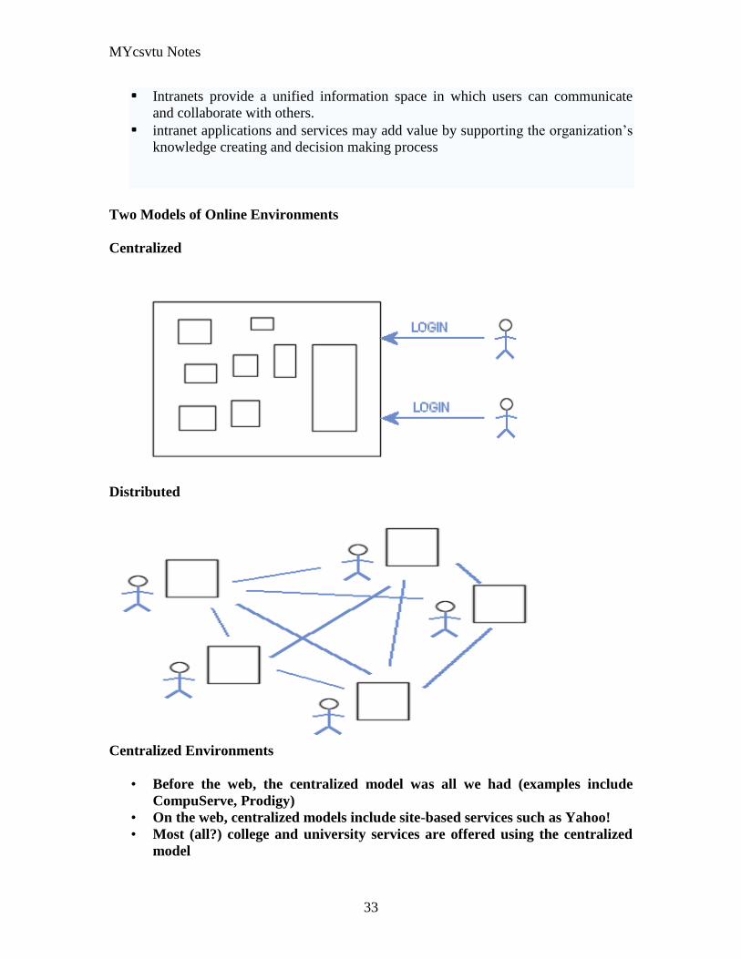
MYcsvtu Notes
33
bull Intranets provide a unified information space in which users can communicate
and collaborate with others
bull intranet applications and services may add value by supporting the organizationlsquos
knowledge creating and decision making process
Two Models of Online Environments
Centralized
Distributed
Centralized Environments
bull Before the web the centralized model was all we had (examples include
CompuServe Prodigy)
bull On the web centralized models include site-based services such as Yahoo
bull Most (all) college and university services are offered using the centralized
model
MYcsvtu Notes
34
bull But centralized environments are static inflexible expensive
Distributed Environments
bull The World Wide Web is an example of a distributed environment
bull Resources access are not centralized but scattered around the world
ndash Resources in the form of a network of connected (via DNS) web servers
ndash Access in the form of a network of connected (via DNS) internet service
providers
ndash Users in the form of individualized and connected (via HTTP) web
browsers
bull The big issue ndash integration ndash that is making different systems work together
Design Principles
Network Design Principles
ndash Specifies how networks differ from traditional learning
ndash The idea is that each principle confers an advantage over non-network
systems
ndash Can be used as a means of evaluating new technology
1 Decentralize
ndash Centralized networks have a characteristic starlsquo shape
bull Some entities have many connections
bull The vast majority have few
bull Eg broadcast network teacher in a classroom
ndash Decentralized networks form a mesh
bull The weight of connections flow is distributed
bull Balanced load = more stable
bull Foster connections between entities fill outlsquo the star
Distribute
ndash Network entities reside in different physical locations
bull Reduces risk of network failure
bull Reduces need for major infrastructure such as powerful servers
large bandwidth massive storage
ndash Examples
bull Peer-to-peer networks such as Kazaa Gnutella
bull Content syndication networks such as RSS
ndash Emphasis is on sharing not copying
bull Locallsquo copies are temporary
MYcsvtu Notes
35
Computer Graphics
Computer Graphics is about animation (films)
Games are very important in Computer Graphics
Medical Imaging is another driving force
Computer Aided Design too
Graphics Definitions
bull Point
ndash a location in space 2D or 3D
ndash sometimes denotes one pixel
bull Line
ndash straight path connecting two points
ndash infinitesimal width consistent density
ndash beginning and end on points
bull Vertex
ndash point in 3D
bull Edge
ndash line in 3D connecting two vertices
bull PolygonFaceFacet
ndash arbitrary shape formed by connected vertices
ndash fundamental unit of 3D computer graphics
bull Raster
ndash derived from TV systems for a row of pixels
ndash commonly referred to as a scanline
ndash does influence algorithms ndash reducing memory requirements parallelism
etc
ndash is the derivation of rasterization scan-line algorithms
Displays
bull Most desktop displays use a cathode ray tube (CRT) while portable computing
devices such as laptops incorporate liquid crystal display (LCD)
bull Because of their slimmer design and smaller energy consumption monitors using
LCD technologies are beginning to replace the venerable CRT on many desktops
Cathode-Ray Tubes
MYcsvtu Notes
36
bull Classical output device is a monitor
bull Cathode-Ray Tube (CRT)
ndash Invented by Karl Ferdinand Braun (1897)
ndash Beam of electrons directed from cathode (-)to phosphor-coated
(fluorescent) screen (anode (+))
ndash Directed by magnetic focusing and deflection coils (anodes) in vacuum
filled tube
ndash Phosphor emits photon of light when hit by an electron of varied
persistence (long 15-20 ms for texts short lt 1ms for animation)
ndash Refresh rate (50-60 Hz 72-76 Hz) to avoid flicker trail
ndash Phosphors are organic compounds characterized by their persistence and
their color (blue red green)
Cathode-Ray Tubes
bull Cathode-Ray Tube (CRT)
ndash Horizontal deflection and vertical deflection direct the electron beam to
any point on the screen
ndash Intensity knob regulates the flow of electrons by controlling the voltage at
the control grid (high voltage reduces the electron density and thus
brightness)
ndash Accelerating voltage from positive coating inside screen (anode screen) or
an accelerating anode
bull Image maintenance
ndash Charge distribution to store picture information
OR
ndash Refresh CRT refreshes the display constantly to maintain phosphor glow
Cathode-Ray Tubes
bullCathode-Ray Tube (CRT)
ndash Horizontal deflection and vertical deflection direct the electron beam to any point
on the screen
ndash Intensity knob regulates the flow of electrons by controlling the voltage at the
control grid (high voltage reduces the electron density and thus brightness)
ndash Accelerating voltage from positive coating inside screen (anode screen) or an
accelerating anode
bullImage maintenance
ndash Charge distribution to store picture information
OR
ndash Refresh CRT refreshes the display constantly to maintain phosphor glow
bull Characteristics of Cathode-Ray Tube (CRT)
MYcsvtu Notes
37
ndash Intensity is proportional to the number of electrons repelled in beam per
second (brightness)
ndash Resolution is the maximum number of points that can be displayed
without overlap is expressed as number of horizontal points by number of
vertical points points are called pixels (picture elements) example
resolution 1024 x 768 pixels Typical resolution is 1280 x 1024 pixels
bull High-definition systems high resolution systems
bull Focusing
ndash Focusing forces the electron beam to converge to a point on the monitor
screen
ndash Can be electrostatic (lens) or magnetic (field)
bull Deflection
ndash Deflection directs the electron beam horizontally andor vertically to any
point on the screen
ndash Can be controlled by electric (deflection plates slide 9) or magnetic fields
(deflection coils slide 5)
ndash Magnetic coils two pairs (topbottom leftright) of tube neck
ndash Electric plates two pairs (horizontal vertical)
Raster-scan Displays
bullVideo displays can be either raster-scan or random-scan displays
bullRaster-scan display is the most common type of monitor using a CRT
bullThe electron beam scans the screen from top to bottom one row at a time Each row is
called a scan line
bullThe electron beam is turned on and off to produce a collection of dots painted one row at
a time These will form the image
bullA raster is a matrix of pixels covering the screen area and is composed of raster lines
Raster-scan Displays
MYcsvtu Notes
38
Raster-scan Displays
bullThe image is stored in a frame buffer containing the total screen area and where each
memory location corresponds to a pixel
bullIn a monochrome system each bit is 1 or 0 for the corresponding pixel to be on or off
(bitmap)
bullThe display processor scans the frame buffer to turn electron beam onoff depending if
the bit is 1 or 0
bullFor color monitors the frame buffer also contains the color of each pixel (color buffer)
as well as other characteristics of the image (gray scale hellip) 8 bitspixel 0255
(pixmap)
bullDepth of the buffer area is the number of bits per pixel (bit planes) up to 24
bullExamples television panels printers PC monitors (99 of raster-scan)
Raster-scan Displays
bullRefresh rate 24 is a minimum to avoid flicker corresponding to 24 Hz (1 Hz = 1 refresh
per second)
bullCurrent raster-scan displays have a refresh rate of at least 60 frames (60 Hz) per second
up to 120 (120 Hz)
bullUses large memory 640x480 307200 bits 38 kB
bullRefresh procedure
MYcsvtu Notes
39
ndashHorizontal retrace ndash beam returns to left of screen
ndashVertical retrace ndash bean returns to top left corner of screen
ndashInterlaced refresh ndash display first even-numbered lines then odd-numbered lines
permits to see the image in half the time
useful for slow refresh rates (30 Hz shows as 60 Hz)
Random-scan Displays
bullRandom scan systems are also called vector stroke-writing or calligraphic displays
bullThe electron beam directly draws the picture in any specified order
bullA pen plotter is an example of such a system
bullPicture is stored in a display list refresh display file vector file or display program as a
set of line drawing commands
bullRefreshes by scanning the list 30 to 60 times per second
bullMore suited for line-drawing applications such as architecture and manufacturing
Random-scan Displays
bullAdvantages
ndashHigh resolution
ndashEasy animation
ndashRequires little memory
bullDisadvantages
ndashRequires intelligent electron beam (processor controlled)
ndashLimited screen density limited to simple line-based images
ndashLimited color capability
bullImproved in the 1960lsquos by the Direct View Storage Tube (DVST) from Tektronix
Color CRT Monitor
Uses different phosphors a combination of Red Green and Blue to produce any color
Two methods
Random scan uses beam penetration
2 layers (Red Green) phosphors low speed electrons excite Red high speed electrons
excite Green interrmediate speed excite both to get yellow and orange Color is
controlled by electron beam voltage
Only produces a restricted set of colors
Raster scan uses a shadow mask with three electron guns Red Green and Blue (RGB
color model) Color is produced by adjusting the intensity level of each electron beam
Produces a wide range of colors from 8 to several millions
Raster scan
Most common as found in televisions
Beam scanned left to right flicked back to rescan from top to bottom then repeated
Repeated at 30Hz per frame sometimes higher to reduce flicker Interlacing scanning
MYcsvtu Notes
40
odd lines in whole screen then even lines is also used to reduce flicker Can also use
high-persistence phosphor to reduce flicker but causes image smearing especially with
significant animation
Resolution typically 512x512 but high-quality screens are available (and becoming more
common) at up to approximately 1600x1200 pixels Sun workstations have screens of
1192x980 pixels
Black amp white screens can display grayscale by varying the intensity of the electron
beam
Colour is achieved using three electron guns which hit red green or blue phosphors
Combining these colours can produce many others including white (all on) Phosphor
dots focused using a shadow mask - makes colour screens lower resolution than
monochrome
Alternative approach beam penetration Special phosphor glows a different colour
depending on intensity of beam
Colour or intensity at pixel held by computerlsquos video card 1 bitpixel can store offon
information hence only black ampwhite More bitspixel give rise to more colour
possibilities eg 8 bitspixel gives rise to 2^8=256 possible colours at any one time
Random Scan (Directed-beam refresh vector display)
Instead of scanning the whole display sequentially and horizontally the random scan
draws the lines to be displayed directly Screen update at gt30Hz to reduce flicker
Jaggies not found and higher resolutions possible (up to 4096x4096 pixels) Colour
achieved using beam penetration generally of poorer quality Eye strain and fatigue still
a problem and vector displays are more expensive
Direct view storage tube (DVST)
Used a lot in analogue storage oscilloscopes
Similar to random scan crt but image maintained by flood guns - no flicker Can be
incrementally updated but not selectively erased image has to be redrawn on completely
erased screen High resolution (typically 4096x3120 pixels) but low contrast low
brightness and difficulty in displaying colour
What is a Multimedia System
bull A system that involves
ndash generation
ndash representation
ndash storage
ndash transmission
ndash search and retrieval
ndash delivery
MYcsvtu Notes
41
of multimedia information
productionauthoring tools
compression and formats
file system design
networking issues
database management
server design streaming
Multimedia System Architecture
Information management subsystem Presentation Query
Storage subsystem Efficiently stored
amp retrieved
Network subsystem Delivery
Adaptation in Multimedia Systems
bull Multimedia systems can profit a lot from personalization
ndash User behavior
ndash User properties
bull Adaptation
ndash Models
ndash Mechanisms
Multimedia in a mobile environment
MYcsvtu Notes
42
bull Applications
ndash Emergency response systems mobile commerce phone service
entertainment games
What is Sound
A ripple is a pressure wave in water created by an object striking the water
Sound is a pressure wave in air created for example by an object such as a string
or our vocal cords vibrating Dark here represents more pressure light represents
less
MYcsvtu Notes
43
Sine Waves Form Pure Tones
This simple sound wave is a Sine Wave a Pure tone produced by a simple vibration
Sine Wave Sample Tone
This can be represented graphically as shown above
Converting Pressure into Voltage
The pressure wave of sound moves a diaphragm in the microphone which produces a
voltage proportional to the pressure of the sound wave at each instant
Animation
MYcsvtu Notes
44
bull Animation is the rapid display of a sequence of images of 2-D artwork or model
positions in order to create an illusion of movement It is an optical illusion of
motion due to the phenomenon of persistence of vision This could be anything
from a flip book to a motion picture film Animation deals with the generation
sequencing and display a set of images which is called frames to create an effect
of visual change or motion similar to a movie film
bull Animation is used in those instance where videography is not possible
Hardware Requirement For Animation
bull Image Generation Tools amp Devices
bull Computer monitors with image display Capability
Software Requirement For Animation
bull Animation creating software
bull Screen Capture Software
bull Animation Clips
bull Software support For High Resolution
bull Recording amp Playback Capability
bull Transition effect
Early animation
There is no single person that can be considered the creator of the art of animation as
there were several people doing several projects which could be considered various types
of animation all around the same time (Short hand-drawn animation scenes could be
presented with the Phenakistoscope the Zoetrope and other optical toys already in the
early 1800s)
The following is a brief listing on those who are often acknowledged as significant to the
development of animation Note that this list is by no means a comprehensive list of
contributors to early animation
Georges Meacuteliegraves was a creator of special effect films such as A Trip to the Moon He
used many techniques ndash one of which was to stop the camera rolling change something
in the scene and then continue rolling the film This is a very similar idea to that of stop-
motion animation Meacuteliegraves accidentally happened upon the technique when his camera
broke down while shooting a bus driving by When the camera was fixed a horse
happened to be passing by just as Meacuteliegraves continued to film The result was that the bus
appeared to change into a horse
MYcsvtu Notes
45
Fantasmagorie by Emile Cohl 1908
Eacutemile Cohl began drawing cartoon strips and created a film in 1908 called
Fantasmagorie The film largely consisted of a stick figure moving about and
encountering all manner of morphing objects such as a wine bottle that transforms into a
flower There were also sections of live action where the animatorlsquos hands would enter
the scene The film was created by drawing each frame on paper and then shooting each
frame onto negative film which gave the picture a blackboard look
Winsor McCay created detailed animations that required a team of artists and painstaking
attention for detail Each frame was drawn on paper requiring backgrounds to be
redrawn as well characters to be animated His films such as Gertie the Dinosaur (1914)
and The Sinking of the Lusitania (1918) were of an impressive scale although The
Sinking of the Lusitania used cels
In 1919 Otto Messmer created the character of Felix the cat for Pat Sullivans animation
studios The importance of Felix lies in the characters strong personality created largely
through gesture and actions
Animation techniques
Animation techniques are incredibly varied and difficult to categorize Techniques are
often related or combined The following is a brief on common types of animation
Again this list is by no means comprehensive
Traditional animation
An example of traditional animation a horse animated by rotoscoping from Edweard
Muybridges 19th century photos
Main article Traditional animation
MYcsvtu Notes
46
Also called cel animation the frames of a traditionally animated movie are hand-drawn
The drawings are traced or copied onto transparent acetate sheets called cels which are
then placed over a painted background and photographed one by one on a rostrum
camera Nowadays the use of cels (and cameras) is mostly obsolete since the drawings
are scanned into computers and digitally transferred directly to 35 mm film The look
of traditional cel animation is still preserved and the character animators work has
remained essentially the same over the past 70 years Because of the digital influence
over modern cel animation it is also known as tradigital animation
Examples The Lion King Spirited Away Les Triplettes de Belleville
Full animation The most common style in animation known for its realistic and often very detailed art
Examples All Disney feature length animated films The Secret of NIMH The Iron Giant
Limited animation A cheaper process of making animated cartoons that does not follow a realistic
approach
Examples The Flintstones Yellow Submarine
Rubber hose The characters are usually cartoony and the animators have a lot of artistic freedom as
rubber hose animations dont have to follow the laws of physics and anatomy in the same
degree as the other main styles in animation
Examples Early Mickey Mouse cartoons Ren and Stimpy Popeye
Rotoscoping A technique where animators trace live action movement frame by frame for use in
animated films
Examples Gullivers Travels American Pop
Stop motion
Stop-motion animation is any type of animation which requires the animator to physically
alter the scene shoot a frame again alter the scene and shoot a frame and so on to create
the animation There are many different types of stop-motion animation some noteable
examples are listed below
Clay animation
MYcsvtu Notes
47
A clay animation scene from a TV commercial
Often abbreviated to claymation this is a type of stop-motion animation using
figures made of clay or a similar malleable material The figures may have an
armature or wire frame inside of them similar to puppet animation (below)
Alternatively the figures may be made entirely of clay such as in the films of
Bruce Bickford where clay creatures morph into a variety of different shapes
Examples Wallace and Gromit Dimensions of Dialogue by Jan Švankmajer The
Amazing Mr Bickford The Trap Door
Cutout animation In this type of stop-motion animation the animation is formed by moving 2-
dimensional pieces of material such as paper or cloth
Examples the animated sequences of Monty Pythons Flying Circus (often
referred to as Dada animation named after the Dada art movement[citation needed]
)
Tale of Tales early episodes of South Park
Silhouette animation A type of cutout animation where the viewer only sees black silhouettes
Example The Adventures of Prince Achmed the worlds oldest surviving
animated feature film from 1926
Graphic animation
Model animation In this form of animation model animated characters interact with and are a part
of the live-action world
Examples The films of Ray Harryhausen (Jason and the Argonauts) and Willis
OBrien (King Kong)
Go motion
Object animation
Pixilation Examples Neighbours
Puppet animation Puppet animation typically involves puppet figures interacting with each other in
a constructed environment in contrast to the real-world interaction in model
MYcsvtu Notes
48
animation (above) The puppets generally have an armature inside of them to
keep them still and steady as well as constraining them to move at particular
joints
Examples The Nightmare Before Christmas Robot Chicken The Tale of the Fox
Brickfilm
Puppetoon
Computer animation
A short gif animation
Like stop motion computer animation encompasses a variety of techniques the unifying
idea being that the animation is created digitally on a computer
2D animation Figures are created andor edited on the computer using 2D bitmap graphics or
created and edited using 2D vector graphics This includes automated
computerized versions of traditional animation techniques such as of tweening
morphing onion skinning and interpolated rotoscoping
Examples A Scanner Darkly Jib Jab
Analog computer animation
Flash animation
PowerPoint animation
A completely synthetic computer-generated scene
3D animation
MYcsvtu Notes
49
Figures are created in the computer using polygons To allow these meshes to
move they are given a digital armature (sculpture) This process is called rigging
Various other techniques can be applied such as mathematical functions
(gravity) simulated fur or hair effects such as fire and water and the use of
motion capture to name but a few
Examples The Incredibles Shrek
Cel-shaded animation
Morph target animation
Skeletal animation
Motion capture
Crowd simulation
Less common techniques
Drawn on film animation A technique where footage is produced by creating the
images directly on film stock
Paint-on-glass animationA technique for making animated films by manipulating slow-
drying oil paints on sheets of glass
Pinscreen animation Makes use of a screen filled with movable pins which can be
moved in or out by pressing an object onto the screen The screen is lit from the side so
that the pins cast shadows The technique has been used to create animated films with a
range of textural effects difficult to achieve with traditional cel animation
Sand animation Sand is moved around on a backlighted or frontlighted piece of glass to
create each frame for an animated film
Multimedia
Multimedia (Lat Multum + Medium) is media that uses multiple forms of information
content and information processing (eg text audio graphics animation video
interactivity) to inform or entertain the (user) audience Multimedia also refers to the use
of (but not limited to) electronic media to store and experience multimedia content
Multimedia is similar to traditional mixed media in fine art but with a broader scope The
term rich media is synonymous for interactive multimedia
Categorization
Multimedia may be broadly divided into linear and non-linear categories Linear active
content progresses without any navigation control for the viewer such as a cinema
presentation Non-linear content offers user interactivity to control progress as used with
MYcsvtu Notes
50
a computer game or used in self-paced computer based training Non-linear content is
also known as hypermedia content
Multimedia presentations can be live or recorded A recorded presentation may allow
interactivity via a navigation system A live multimedia presentation may allow
interactivity via interaction with the presenter or performer
There are 2 basic way to represent some information
Unimedium Presentation
Multimedia Presentation
In case of computer system the commonly used medioa for the purpose of storage
access and transmission of information are
bull Text
bull Graphics
bull Animation
bull Audio
bull Video
Multimedia Computer System require
bull Faster CPU
bull Larger Storage Devices
bull Larger Main Memory
bull Good Graphics Terminal
bull IO devices required to play an audio associated with the program
Transmission Mode
bull Asynchronous
bull Synchronous
bull Isochronous
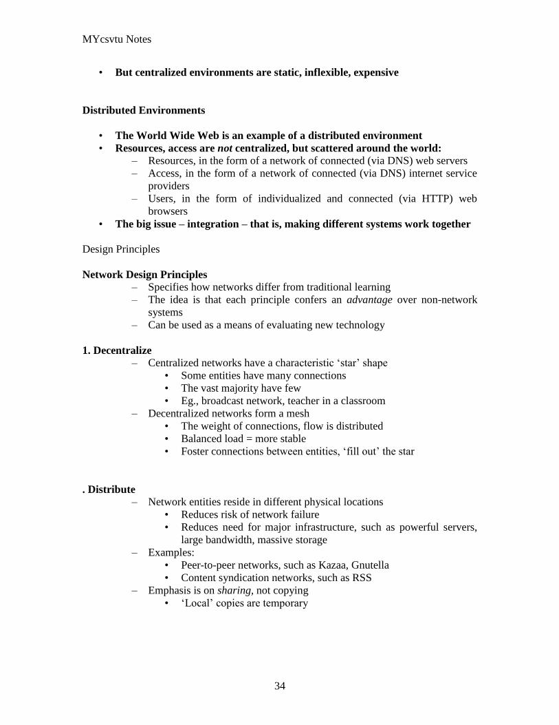
MYcsvtu Notes
34
bull But centralized environments are static inflexible expensive
Distributed Environments
bull The World Wide Web is an example of a distributed environment
bull Resources access are not centralized but scattered around the world
ndash Resources in the form of a network of connected (via DNS) web servers
ndash Access in the form of a network of connected (via DNS) internet service
providers
ndash Users in the form of individualized and connected (via HTTP) web
browsers
bull The big issue ndash integration ndash that is making different systems work together
Design Principles
Network Design Principles
ndash Specifies how networks differ from traditional learning
ndash The idea is that each principle confers an advantage over non-network
systems
ndash Can be used as a means of evaluating new technology
1 Decentralize
ndash Centralized networks have a characteristic starlsquo shape
bull Some entities have many connections
bull The vast majority have few
bull Eg broadcast network teacher in a classroom
ndash Decentralized networks form a mesh
bull The weight of connections flow is distributed
bull Balanced load = more stable
bull Foster connections between entities fill outlsquo the star
Distribute
ndash Network entities reside in different physical locations
bull Reduces risk of network failure
bull Reduces need for major infrastructure such as powerful servers
large bandwidth massive storage
ndash Examples
bull Peer-to-peer networks such as Kazaa Gnutella
bull Content syndication networks such as RSS
ndash Emphasis is on sharing not copying
bull Locallsquo copies are temporary
MYcsvtu Notes
35
Computer Graphics
Computer Graphics is about animation (films)
Games are very important in Computer Graphics
Medical Imaging is another driving force
Computer Aided Design too
Graphics Definitions
bull Point
ndash a location in space 2D or 3D
ndash sometimes denotes one pixel
bull Line
ndash straight path connecting two points
ndash infinitesimal width consistent density
ndash beginning and end on points
bull Vertex
ndash point in 3D
bull Edge
ndash line in 3D connecting two vertices
bull PolygonFaceFacet
ndash arbitrary shape formed by connected vertices
ndash fundamental unit of 3D computer graphics
bull Raster
ndash derived from TV systems for a row of pixels
ndash commonly referred to as a scanline
ndash does influence algorithms ndash reducing memory requirements parallelism
etc
ndash is the derivation of rasterization scan-line algorithms
Displays
bull Most desktop displays use a cathode ray tube (CRT) while portable computing
devices such as laptops incorporate liquid crystal display (LCD)
bull Because of their slimmer design and smaller energy consumption monitors using
LCD technologies are beginning to replace the venerable CRT on many desktops
Cathode-Ray Tubes
MYcsvtu Notes
36
bull Classical output device is a monitor
bull Cathode-Ray Tube (CRT)
ndash Invented by Karl Ferdinand Braun (1897)
ndash Beam of electrons directed from cathode (-)to phosphor-coated
(fluorescent) screen (anode (+))
ndash Directed by magnetic focusing and deflection coils (anodes) in vacuum
filled tube
ndash Phosphor emits photon of light when hit by an electron of varied
persistence (long 15-20 ms for texts short lt 1ms for animation)
ndash Refresh rate (50-60 Hz 72-76 Hz) to avoid flicker trail
ndash Phosphors are organic compounds characterized by their persistence and
their color (blue red green)
Cathode-Ray Tubes
bull Cathode-Ray Tube (CRT)
ndash Horizontal deflection and vertical deflection direct the electron beam to
any point on the screen
ndash Intensity knob regulates the flow of electrons by controlling the voltage at
the control grid (high voltage reduces the electron density and thus
brightness)
ndash Accelerating voltage from positive coating inside screen (anode screen) or
an accelerating anode
bull Image maintenance
ndash Charge distribution to store picture information
OR
ndash Refresh CRT refreshes the display constantly to maintain phosphor glow
Cathode-Ray Tubes
bullCathode-Ray Tube (CRT)
ndash Horizontal deflection and vertical deflection direct the electron beam to any point
on the screen
ndash Intensity knob regulates the flow of electrons by controlling the voltage at the
control grid (high voltage reduces the electron density and thus brightness)
ndash Accelerating voltage from positive coating inside screen (anode screen) or an
accelerating anode
bullImage maintenance
ndash Charge distribution to store picture information
OR
ndash Refresh CRT refreshes the display constantly to maintain phosphor glow
bull Characteristics of Cathode-Ray Tube (CRT)
MYcsvtu Notes
37
ndash Intensity is proportional to the number of electrons repelled in beam per
second (brightness)
ndash Resolution is the maximum number of points that can be displayed
without overlap is expressed as number of horizontal points by number of
vertical points points are called pixels (picture elements) example
resolution 1024 x 768 pixels Typical resolution is 1280 x 1024 pixels
bull High-definition systems high resolution systems
bull Focusing
ndash Focusing forces the electron beam to converge to a point on the monitor
screen
ndash Can be electrostatic (lens) or magnetic (field)
bull Deflection
ndash Deflection directs the electron beam horizontally andor vertically to any
point on the screen
ndash Can be controlled by electric (deflection plates slide 9) or magnetic fields
(deflection coils slide 5)
ndash Magnetic coils two pairs (topbottom leftright) of tube neck
ndash Electric plates two pairs (horizontal vertical)
Raster-scan Displays
bullVideo displays can be either raster-scan or random-scan displays
bullRaster-scan display is the most common type of monitor using a CRT
bullThe electron beam scans the screen from top to bottom one row at a time Each row is
called a scan line
bullThe electron beam is turned on and off to produce a collection of dots painted one row at
a time These will form the image
bullA raster is a matrix of pixels covering the screen area and is composed of raster lines
Raster-scan Displays
MYcsvtu Notes
38
Raster-scan Displays
bullThe image is stored in a frame buffer containing the total screen area and where each
memory location corresponds to a pixel
bullIn a monochrome system each bit is 1 or 0 for the corresponding pixel to be on or off
(bitmap)
bullThe display processor scans the frame buffer to turn electron beam onoff depending if
the bit is 1 or 0
bullFor color monitors the frame buffer also contains the color of each pixel (color buffer)
as well as other characteristics of the image (gray scale hellip) 8 bitspixel 0255
(pixmap)
bullDepth of the buffer area is the number of bits per pixel (bit planes) up to 24
bullExamples television panels printers PC monitors (99 of raster-scan)
Raster-scan Displays
bullRefresh rate 24 is a minimum to avoid flicker corresponding to 24 Hz (1 Hz = 1 refresh
per second)
bullCurrent raster-scan displays have a refresh rate of at least 60 frames (60 Hz) per second
up to 120 (120 Hz)
bullUses large memory 640x480 307200 bits 38 kB
bullRefresh procedure
MYcsvtu Notes
39
ndashHorizontal retrace ndash beam returns to left of screen
ndashVertical retrace ndash bean returns to top left corner of screen
ndashInterlaced refresh ndash display first even-numbered lines then odd-numbered lines
permits to see the image in half the time
useful for slow refresh rates (30 Hz shows as 60 Hz)
Random-scan Displays
bullRandom scan systems are also called vector stroke-writing or calligraphic displays
bullThe electron beam directly draws the picture in any specified order
bullA pen plotter is an example of such a system
bullPicture is stored in a display list refresh display file vector file or display program as a
set of line drawing commands
bullRefreshes by scanning the list 30 to 60 times per second
bullMore suited for line-drawing applications such as architecture and manufacturing
Random-scan Displays
bullAdvantages
ndashHigh resolution
ndashEasy animation
ndashRequires little memory
bullDisadvantages
ndashRequires intelligent electron beam (processor controlled)
ndashLimited screen density limited to simple line-based images
ndashLimited color capability
bullImproved in the 1960lsquos by the Direct View Storage Tube (DVST) from Tektronix
Color CRT Monitor
Uses different phosphors a combination of Red Green and Blue to produce any color
Two methods
Random scan uses beam penetration
2 layers (Red Green) phosphors low speed electrons excite Red high speed electrons
excite Green interrmediate speed excite both to get yellow and orange Color is
controlled by electron beam voltage
Only produces a restricted set of colors
Raster scan uses a shadow mask with three electron guns Red Green and Blue (RGB
color model) Color is produced by adjusting the intensity level of each electron beam
Produces a wide range of colors from 8 to several millions
Raster scan
Most common as found in televisions
Beam scanned left to right flicked back to rescan from top to bottom then repeated
Repeated at 30Hz per frame sometimes higher to reduce flicker Interlacing scanning
MYcsvtu Notes
40
odd lines in whole screen then even lines is also used to reduce flicker Can also use
high-persistence phosphor to reduce flicker but causes image smearing especially with
significant animation
Resolution typically 512x512 but high-quality screens are available (and becoming more
common) at up to approximately 1600x1200 pixels Sun workstations have screens of
1192x980 pixels
Black amp white screens can display grayscale by varying the intensity of the electron
beam
Colour is achieved using three electron guns which hit red green or blue phosphors
Combining these colours can produce many others including white (all on) Phosphor
dots focused using a shadow mask - makes colour screens lower resolution than
monochrome
Alternative approach beam penetration Special phosphor glows a different colour
depending on intensity of beam
Colour or intensity at pixel held by computerlsquos video card 1 bitpixel can store offon
information hence only black ampwhite More bitspixel give rise to more colour
possibilities eg 8 bitspixel gives rise to 2^8=256 possible colours at any one time
Random Scan (Directed-beam refresh vector display)
Instead of scanning the whole display sequentially and horizontally the random scan
draws the lines to be displayed directly Screen update at gt30Hz to reduce flicker
Jaggies not found and higher resolutions possible (up to 4096x4096 pixels) Colour
achieved using beam penetration generally of poorer quality Eye strain and fatigue still
a problem and vector displays are more expensive
Direct view storage tube (DVST)
Used a lot in analogue storage oscilloscopes
Similar to random scan crt but image maintained by flood guns - no flicker Can be
incrementally updated but not selectively erased image has to be redrawn on completely
erased screen High resolution (typically 4096x3120 pixels) but low contrast low
brightness and difficulty in displaying colour
What is a Multimedia System
bull A system that involves
ndash generation
ndash representation
ndash storage
ndash transmission
ndash search and retrieval
ndash delivery
MYcsvtu Notes
41
of multimedia information
productionauthoring tools
compression and formats
file system design
networking issues
database management
server design streaming
Multimedia System Architecture
Information management subsystem Presentation Query
Storage subsystem Efficiently stored
amp retrieved
Network subsystem Delivery
Adaptation in Multimedia Systems
bull Multimedia systems can profit a lot from personalization
ndash User behavior
ndash User properties
bull Adaptation
ndash Models
ndash Mechanisms
Multimedia in a mobile environment
MYcsvtu Notes
42
bull Applications
ndash Emergency response systems mobile commerce phone service
entertainment games
What is Sound
A ripple is a pressure wave in water created by an object striking the water
Sound is a pressure wave in air created for example by an object such as a string
or our vocal cords vibrating Dark here represents more pressure light represents
less
MYcsvtu Notes
43
Sine Waves Form Pure Tones
This simple sound wave is a Sine Wave a Pure tone produced by a simple vibration
Sine Wave Sample Tone
This can be represented graphically as shown above
Converting Pressure into Voltage
The pressure wave of sound moves a diaphragm in the microphone which produces a
voltage proportional to the pressure of the sound wave at each instant
Animation
MYcsvtu Notes
44
bull Animation is the rapid display of a sequence of images of 2-D artwork or model
positions in order to create an illusion of movement It is an optical illusion of
motion due to the phenomenon of persistence of vision This could be anything
from a flip book to a motion picture film Animation deals with the generation
sequencing and display a set of images which is called frames to create an effect
of visual change or motion similar to a movie film
bull Animation is used in those instance where videography is not possible
Hardware Requirement For Animation
bull Image Generation Tools amp Devices
bull Computer monitors with image display Capability
Software Requirement For Animation
bull Animation creating software
bull Screen Capture Software
bull Animation Clips
bull Software support For High Resolution
bull Recording amp Playback Capability
bull Transition effect
Early animation
There is no single person that can be considered the creator of the art of animation as
there were several people doing several projects which could be considered various types
of animation all around the same time (Short hand-drawn animation scenes could be
presented with the Phenakistoscope the Zoetrope and other optical toys already in the
early 1800s)
The following is a brief listing on those who are often acknowledged as significant to the
development of animation Note that this list is by no means a comprehensive list of
contributors to early animation
Georges Meacuteliegraves was a creator of special effect films such as A Trip to the Moon He
used many techniques ndash one of which was to stop the camera rolling change something
in the scene and then continue rolling the film This is a very similar idea to that of stop-
motion animation Meacuteliegraves accidentally happened upon the technique when his camera
broke down while shooting a bus driving by When the camera was fixed a horse
happened to be passing by just as Meacuteliegraves continued to film The result was that the bus
appeared to change into a horse
MYcsvtu Notes
45
Fantasmagorie by Emile Cohl 1908
Eacutemile Cohl began drawing cartoon strips and created a film in 1908 called
Fantasmagorie The film largely consisted of a stick figure moving about and
encountering all manner of morphing objects such as a wine bottle that transforms into a
flower There were also sections of live action where the animatorlsquos hands would enter
the scene The film was created by drawing each frame on paper and then shooting each
frame onto negative film which gave the picture a blackboard look
Winsor McCay created detailed animations that required a team of artists and painstaking
attention for detail Each frame was drawn on paper requiring backgrounds to be
redrawn as well characters to be animated His films such as Gertie the Dinosaur (1914)
and The Sinking of the Lusitania (1918) were of an impressive scale although The
Sinking of the Lusitania used cels
In 1919 Otto Messmer created the character of Felix the cat for Pat Sullivans animation
studios The importance of Felix lies in the characters strong personality created largely
through gesture and actions
Animation techniques
Animation techniques are incredibly varied and difficult to categorize Techniques are
often related or combined The following is a brief on common types of animation
Again this list is by no means comprehensive
Traditional animation
An example of traditional animation a horse animated by rotoscoping from Edweard
Muybridges 19th century photos
Main article Traditional animation
MYcsvtu Notes
46
Also called cel animation the frames of a traditionally animated movie are hand-drawn
The drawings are traced or copied onto transparent acetate sheets called cels which are
then placed over a painted background and photographed one by one on a rostrum
camera Nowadays the use of cels (and cameras) is mostly obsolete since the drawings
are scanned into computers and digitally transferred directly to 35 mm film The look
of traditional cel animation is still preserved and the character animators work has
remained essentially the same over the past 70 years Because of the digital influence
over modern cel animation it is also known as tradigital animation
Examples The Lion King Spirited Away Les Triplettes de Belleville
Full animation The most common style in animation known for its realistic and often very detailed art
Examples All Disney feature length animated films The Secret of NIMH The Iron Giant
Limited animation A cheaper process of making animated cartoons that does not follow a realistic
approach
Examples The Flintstones Yellow Submarine
Rubber hose The characters are usually cartoony and the animators have a lot of artistic freedom as
rubber hose animations dont have to follow the laws of physics and anatomy in the same
degree as the other main styles in animation
Examples Early Mickey Mouse cartoons Ren and Stimpy Popeye
Rotoscoping A technique where animators trace live action movement frame by frame for use in
animated films
Examples Gullivers Travels American Pop
Stop motion
Stop-motion animation is any type of animation which requires the animator to physically
alter the scene shoot a frame again alter the scene and shoot a frame and so on to create
the animation There are many different types of stop-motion animation some noteable
examples are listed below
Clay animation
MYcsvtu Notes
47
A clay animation scene from a TV commercial
Often abbreviated to claymation this is a type of stop-motion animation using
figures made of clay or a similar malleable material The figures may have an
armature or wire frame inside of them similar to puppet animation (below)
Alternatively the figures may be made entirely of clay such as in the films of
Bruce Bickford where clay creatures morph into a variety of different shapes
Examples Wallace and Gromit Dimensions of Dialogue by Jan Švankmajer The
Amazing Mr Bickford The Trap Door
Cutout animation In this type of stop-motion animation the animation is formed by moving 2-
dimensional pieces of material such as paper or cloth
Examples the animated sequences of Monty Pythons Flying Circus (often
referred to as Dada animation named after the Dada art movement[citation needed]
)
Tale of Tales early episodes of South Park
Silhouette animation A type of cutout animation where the viewer only sees black silhouettes
Example The Adventures of Prince Achmed the worlds oldest surviving
animated feature film from 1926
Graphic animation
Model animation In this form of animation model animated characters interact with and are a part
of the live-action world
Examples The films of Ray Harryhausen (Jason and the Argonauts) and Willis
OBrien (King Kong)
Go motion
Object animation
Pixilation Examples Neighbours
Puppet animation Puppet animation typically involves puppet figures interacting with each other in
a constructed environment in contrast to the real-world interaction in model
MYcsvtu Notes
48
animation (above) The puppets generally have an armature inside of them to
keep them still and steady as well as constraining them to move at particular
joints
Examples The Nightmare Before Christmas Robot Chicken The Tale of the Fox
Brickfilm
Puppetoon
Computer animation
A short gif animation
Like stop motion computer animation encompasses a variety of techniques the unifying
idea being that the animation is created digitally on a computer
2D animation Figures are created andor edited on the computer using 2D bitmap graphics or
created and edited using 2D vector graphics This includes automated
computerized versions of traditional animation techniques such as of tweening
morphing onion skinning and interpolated rotoscoping
Examples A Scanner Darkly Jib Jab
Analog computer animation
Flash animation
PowerPoint animation
A completely synthetic computer-generated scene
3D animation
MYcsvtu Notes
49
Figures are created in the computer using polygons To allow these meshes to
move they are given a digital armature (sculpture) This process is called rigging
Various other techniques can be applied such as mathematical functions
(gravity) simulated fur or hair effects such as fire and water and the use of
motion capture to name but a few
Examples The Incredibles Shrek
Cel-shaded animation
Morph target animation
Skeletal animation
Motion capture
Crowd simulation
Less common techniques
Drawn on film animation A technique where footage is produced by creating the
images directly on film stock
Paint-on-glass animationA technique for making animated films by manipulating slow-
drying oil paints on sheets of glass
Pinscreen animation Makes use of a screen filled with movable pins which can be
moved in or out by pressing an object onto the screen The screen is lit from the side so
that the pins cast shadows The technique has been used to create animated films with a
range of textural effects difficult to achieve with traditional cel animation
Sand animation Sand is moved around on a backlighted or frontlighted piece of glass to
create each frame for an animated film
Multimedia
Multimedia (Lat Multum + Medium) is media that uses multiple forms of information
content and information processing (eg text audio graphics animation video
interactivity) to inform or entertain the (user) audience Multimedia also refers to the use
of (but not limited to) electronic media to store and experience multimedia content
Multimedia is similar to traditional mixed media in fine art but with a broader scope The
term rich media is synonymous for interactive multimedia
Categorization
Multimedia may be broadly divided into linear and non-linear categories Linear active
content progresses without any navigation control for the viewer such as a cinema
presentation Non-linear content offers user interactivity to control progress as used with
MYcsvtu Notes
50
a computer game or used in self-paced computer based training Non-linear content is
also known as hypermedia content
Multimedia presentations can be live or recorded A recorded presentation may allow
interactivity via a navigation system A live multimedia presentation may allow
interactivity via interaction with the presenter or performer
There are 2 basic way to represent some information
Unimedium Presentation
Multimedia Presentation
In case of computer system the commonly used medioa for the purpose of storage
access and transmission of information are
bull Text
bull Graphics
bull Animation
bull Audio
bull Video
Multimedia Computer System require
bull Faster CPU
bull Larger Storage Devices
bull Larger Main Memory
bull Good Graphics Terminal
bull IO devices required to play an audio associated with the program
Transmission Mode
bull Asynchronous
bull Synchronous
bull Isochronous
MYcsvtu Notes
36
bull Classical output device is a monitor
bull Cathode-Ray Tube (CRT)
ndash Invented by Karl Ferdinand Braun (1897)
ndash Beam of electrons directed from cathode (-)to phosphor-coated
(fluorescent) screen (anode (+))
ndash Directed by magnetic focusing and deflection coils (anodes) in vacuum
filled tube
ndash Phosphor emits photon of light when hit by an electron of varied
persistence (long 15-20 ms for texts short lt 1ms for animation)
ndash Refresh rate (50-60 Hz 72-76 Hz) to avoid flicker trail
ndash Phosphors are organic compounds characterized by their persistence and
their color (blue red green)
Cathode-Ray Tubes
bull Cathode-Ray Tube (CRT)
ndash Horizontal deflection and vertical deflection direct the electron beam to
any point on the screen
ndash Intensity knob regulates the flow of electrons by controlling the voltage at
the control grid (high voltage reduces the electron density and thus
brightness)
ndash Accelerating voltage from positive coating inside screen (anode screen) or
an accelerating anode
bull Image maintenance
ndash Charge distribution to store picture information
OR
ndash Refresh CRT refreshes the display constantly to maintain phosphor glow
Cathode-Ray Tubes
bullCathode-Ray Tube (CRT)
ndash Horizontal deflection and vertical deflection direct the electron beam to any point
on the screen
ndash Intensity knob regulates the flow of electrons by controlling the voltage at the
control grid (high voltage reduces the electron density and thus brightness)
ndash Accelerating voltage from positive coating inside screen (anode screen) or an
accelerating anode
bullImage maintenance
ndash Charge distribution to store picture information
OR
ndash Refresh CRT refreshes the display constantly to maintain phosphor glow
bull Characteristics of Cathode-Ray Tube (CRT)
MYcsvtu Notes
37
ndash Intensity is proportional to the number of electrons repelled in beam per
second (brightness)
ndash Resolution is the maximum number of points that can be displayed
without overlap is expressed as number of horizontal points by number of
vertical points points are called pixels (picture elements) example
resolution 1024 x 768 pixels Typical resolution is 1280 x 1024 pixels
bull High-definition systems high resolution systems
bull Focusing
ndash Focusing forces the electron beam to converge to a point on the monitor
screen
ndash Can be electrostatic (lens) or magnetic (field)
bull Deflection
ndash Deflection directs the electron beam horizontally andor vertically to any
point on the screen
ndash Can be controlled by electric (deflection plates slide 9) or magnetic fields
(deflection coils slide 5)
ndash Magnetic coils two pairs (topbottom leftright) of tube neck
ndash Electric plates two pairs (horizontal vertical)
Raster-scan Displays
bullVideo displays can be either raster-scan or random-scan displays
bullRaster-scan display is the most common type of monitor using a CRT
bullThe electron beam scans the screen from top to bottom one row at a time Each row is
called a scan line
bullThe electron beam is turned on and off to produce a collection of dots painted one row at
a time These will form the image
bullA raster is a matrix of pixels covering the screen area and is composed of raster lines
Raster-scan Displays
MYcsvtu Notes
38
Raster-scan Displays
bullThe image is stored in a frame buffer containing the total screen area and where each
memory location corresponds to a pixel
bullIn a monochrome system each bit is 1 or 0 for the corresponding pixel to be on or off
(bitmap)
bullThe display processor scans the frame buffer to turn electron beam onoff depending if
the bit is 1 or 0
bullFor color monitors the frame buffer also contains the color of each pixel (color buffer)
as well as other characteristics of the image (gray scale hellip) 8 bitspixel 0255
(pixmap)
bullDepth of the buffer area is the number of bits per pixel (bit planes) up to 24
bullExamples television panels printers PC monitors (99 of raster-scan)
Raster-scan Displays
bullRefresh rate 24 is a minimum to avoid flicker corresponding to 24 Hz (1 Hz = 1 refresh
per second)
bullCurrent raster-scan displays have a refresh rate of at least 60 frames (60 Hz) per second
up to 120 (120 Hz)
bullUses large memory 640x480 307200 bits 38 kB
bullRefresh procedure
MYcsvtu Notes
39
ndashHorizontal retrace ndash beam returns to left of screen
ndashVertical retrace ndash bean returns to top left corner of screen
ndashInterlaced refresh ndash display first even-numbered lines then odd-numbered lines
permits to see the image in half the time
useful for slow refresh rates (30 Hz shows as 60 Hz)
Random-scan Displays
bullRandom scan systems are also called vector stroke-writing or calligraphic displays
bullThe electron beam directly draws the picture in any specified order
bullA pen plotter is an example of such a system
bullPicture is stored in a display list refresh display file vector file or display program as a
set of line drawing commands
bullRefreshes by scanning the list 30 to 60 times per second
bullMore suited for line-drawing applications such as architecture and manufacturing
Random-scan Displays
bullAdvantages
ndashHigh resolution
ndashEasy animation
ndashRequires little memory
bullDisadvantages
ndashRequires intelligent electron beam (processor controlled)
ndashLimited screen density limited to simple line-based images
ndashLimited color capability
bullImproved in the 1960lsquos by the Direct View Storage Tube (DVST) from Tektronix
Color CRT Monitor
Uses different phosphors a combination of Red Green and Blue to produce any color
Two methods
Random scan uses beam penetration
2 layers (Red Green) phosphors low speed electrons excite Red high speed electrons
excite Green interrmediate speed excite both to get yellow and orange Color is
controlled by electron beam voltage
Only produces a restricted set of colors
Raster scan uses a shadow mask with three electron guns Red Green and Blue (RGB
color model) Color is produced by adjusting the intensity level of each electron beam
Produces a wide range of colors from 8 to several millions
Raster scan
Most common as found in televisions
Beam scanned left to right flicked back to rescan from top to bottom then repeated
Repeated at 30Hz per frame sometimes higher to reduce flicker Interlacing scanning
MYcsvtu Notes
40
odd lines in whole screen then even lines is also used to reduce flicker Can also use
high-persistence phosphor to reduce flicker but causes image smearing especially with
significant animation
Resolution typically 512x512 but high-quality screens are available (and becoming more
common) at up to approximately 1600x1200 pixels Sun workstations have screens of
1192x980 pixels
Black amp white screens can display grayscale by varying the intensity of the electron
beam
Colour is achieved using three electron guns which hit red green or blue phosphors
Combining these colours can produce many others including white (all on) Phosphor
dots focused using a shadow mask - makes colour screens lower resolution than
monochrome
Alternative approach beam penetration Special phosphor glows a different colour
depending on intensity of beam
Colour or intensity at pixel held by computerlsquos video card 1 bitpixel can store offon
information hence only black ampwhite More bitspixel give rise to more colour
possibilities eg 8 bitspixel gives rise to 2^8=256 possible colours at any one time
Random Scan (Directed-beam refresh vector display)
Instead of scanning the whole display sequentially and horizontally the random scan
draws the lines to be displayed directly Screen update at gt30Hz to reduce flicker
Jaggies not found and higher resolutions possible (up to 4096x4096 pixels) Colour
achieved using beam penetration generally of poorer quality Eye strain and fatigue still
a problem and vector displays are more expensive
Direct view storage tube (DVST)
Used a lot in analogue storage oscilloscopes
Similar to random scan crt but image maintained by flood guns - no flicker Can be
incrementally updated but not selectively erased image has to be redrawn on completely
erased screen High resolution (typically 4096x3120 pixels) but low contrast low
brightness and difficulty in displaying colour
What is a Multimedia System
bull A system that involves
ndash generation
ndash representation
ndash storage
ndash transmission
ndash search and retrieval
ndash delivery
MYcsvtu Notes
41
of multimedia information
productionauthoring tools
compression and formats
file system design
networking issues
database management
server design streaming
Multimedia System Architecture
Information management subsystem Presentation Query
Storage subsystem Efficiently stored
amp retrieved
Network subsystem Delivery
Adaptation in Multimedia Systems
bull Multimedia systems can profit a lot from personalization
ndash User behavior
ndash User properties
bull Adaptation
ndash Models
ndash Mechanisms
Multimedia in a mobile environment
MYcsvtu Notes
42
bull Applications
ndash Emergency response systems mobile commerce phone service
entertainment games
What is Sound
A ripple is a pressure wave in water created by an object striking the water
Sound is a pressure wave in air created for example by an object such as a string
or our vocal cords vibrating Dark here represents more pressure light represents
less
MYcsvtu Notes
43
Sine Waves Form Pure Tones
This simple sound wave is a Sine Wave a Pure tone produced by a simple vibration
Sine Wave Sample Tone
This can be represented graphically as shown above
Converting Pressure into Voltage
The pressure wave of sound moves a diaphragm in the microphone which produces a
voltage proportional to the pressure of the sound wave at each instant
Animation
MYcsvtu Notes
44
bull Animation is the rapid display of a sequence of images of 2-D artwork or model
positions in order to create an illusion of movement It is an optical illusion of
motion due to the phenomenon of persistence of vision This could be anything
from a flip book to a motion picture film Animation deals with the generation
sequencing and display a set of images which is called frames to create an effect
of visual change or motion similar to a movie film
bull Animation is used in those instance where videography is not possible
Hardware Requirement For Animation
bull Image Generation Tools amp Devices
bull Computer monitors with image display Capability
Software Requirement For Animation
bull Animation creating software
bull Screen Capture Software
bull Animation Clips
bull Software support For High Resolution
bull Recording amp Playback Capability
bull Transition effect
Early animation
There is no single person that can be considered the creator of the art of animation as
there were several people doing several projects which could be considered various types
of animation all around the same time (Short hand-drawn animation scenes could be
presented with the Phenakistoscope the Zoetrope and other optical toys already in the
early 1800s)
The following is a brief listing on those who are often acknowledged as significant to the
development of animation Note that this list is by no means a comprehensive list of
contributors to early animation
Georges Meacuteliegraves was a creator of special effect films such as A Trip to the Moon He
used many techniques ndash one of which was to stop the camera rolling change something
in the scene and then continue rolling the film This is a very similar idea to that of stop-
motion animation Meacuteliegraves accidentally happened upon the technique when his camera
broke down while shooting a bus driving by When the camera was fixed a horse
happened to be passing by just as Meacuteliegraves continued to film The result was that the bus
appeared to change into a horse
MYcsvtu Notes
45
Fantasmagorie by Emile Cohl 1908
Eacutemile Cohl began drawing cartoon strips and created a film in 1908 called
Fantasmagorie The film largely consisted of a stick figure moving about and
encountering all manner of morphing objects such as a wine bottle that transforms into a
flower There were also sections of live action where the animatorlsquos hands would enter
the scene The film was created by drawing each frame on paper and then shooting each
frame onto negative film which gave the picture a blackboard look
Winsor McCay created detailed animations that required a team of artists and painstaking
attention for detail Each frame was drawn on paper requiring backgrounds to be
redrawn as well characters to be animated His films such as Gertie the Dinosaur (1914)
and The Sinking of the Lusitania (1918) were of an impressive scale although The
Sinking of the Lusitania used cels
In 1919 Otto Messmer created the character of Felix the cat for Pat Sullivans animation
studios The importance of Felix lies in the characters strong personality created largely
through gesture and actions
Animation techniques
Animation techniques are incredibly varied and difficult to categorize Techniques are
often related or combined The following is a brief on common types of animation
Again this list is by no means comprehensive
Traditional animation
An example of traditional animation a horse animated by rotoscoping from Edweard
Muybridges 19th century photos
Main article Traditional animation
MYcsvtu Notes
46
Also called cel animation the frames of a traditionally animated movie are hand-drawn
The drawings are traced or copied onto transparent acetate sheets called cels which are
then placed over a painted background and photographed one by one on a rostrum
camera Nowadays the use of cels (and cameras) is mostly obsolete since the drawings
are scanned into computers and digitally transferred directly to 35 mm film The look
of traditional cel animation is still preserved and the character animators work has
remained essentially the same over the past 70 years Because of the digital influence
over modern cel animation it is also known as tradigital animation
Examples The Lion King Spirited Away Les Triplettes de Belleville
Full animation The most common style in animation known for its realistic and often very detailed art
Examples All Disney feature length animated films The Secret of NIMH The Iron Giant
Limited animation A cheaper process of making animated cartoons that does not follow a realistic
approach
Examples The Flintstones Yellow Submarine
Rubber hose The characters are usually cartoony and the animators have a lot of artistic freedom as
rubber hose animations dont have to follow the laws of physics and anatomy in the same
degree as the other main styles in animation
Examples Early Mickey Mouse cartoons Ren and Stimpy Popeye
Rotoscoping A technique where animators trace live action movement frame by frame for use in
animated films
Examples Gullivers Travels American Pop
Stop motion
Stop-motion animation is any type of animation which requires the animator to physically
alter the scene shoot a frame again alter the scene and shoot a frame and so on to create
the animation There are many different types of stop-motion animation some noteable
examples are listed below
Clay animation
MYcsvtu Notes
47
A clay animation scene from a TV commercial
Often abbreviated to claymation this is a type of stop-motion animation using
figures made of clay or a similar malleable material The figures may have an
armature or wire frame inside of them similar to puppet animation (below)
Alternatively the figures may be made entirely of clay such as in the films of
Bruce Bickford where clay creatures morph into a variety of different shapes
Examples Wallace and Gromit Dimensions of Dialogue by Jan Švankmajer The
Amazing Mr Bickford The Trap Door
Cutout animation In this type of stop-motion animation the animation is formed by moving 2-
dimensional pieces of material such as paper or cloth
Examples the animated sequences of Monty Pythons Flying Circus (often
referred to as Dada animation named after the Dada art movement[citation needed]
)
Tale of Tales early episodes of South Park
Silhouette animation A type of cutout animation where the viewer only sees black silhouettes
Example The Adventures of Prince Achmed the worlds oldest surviving
animated feature film from 1926
Graphic animation
Model animation In this form of animation model animated characters interact with and are a part
of the live-action world
Examples The films of Ray Harryhausen (Jason and the Argonauts) and Willis
OBrien (King Kong)
Go motion
Object animation
Pixilation Examples Neighbours
Puppet animation Puppet animation typically involves puppet figures interacting with each other in
a constructed environment in contrast to the real-world interaction in model
MYcsvtu Notes
48
animation (above) The puppets generally have an armature inside of them to
keep them still and steady as well as constraining them to move at particular
joints
Examples The Nightmare Before Christmas Robot Chicken The Tale of the Fox
Brickfilm
Puppetoon
Computer animation
A short gif animation
Like stop motion computer animation encompasses a variety of techniques the unifying
idea being that the animation is created digitally on a computer
2D animation Figures are created andor edited on the computer using 2D bitmap graphics or
created and edited using 2D vector graphics This includes automated
computerized versions of traditional animation techniques such as of tweening
morphing onion skinning and interpolated rotoscoping
Examples A Scanner Darkly Jib Jab
Analog computer animation
Flash animation
PowerPoint animation
A completely synthetic computer-generated scene
3D animation
MYcsvtu Notes
49
Figures are created in the computer using polygons To allow these meshes to
move they are given a digital armature (sculpture) This process is called rigging
Various other techniques can be applied such as mathematical functions
(gravity) simulated fur or hair effects such as fire and water and the use of
motion capture to name but a few
Examples The Incredibles Shrek
Cel-shaded animation
Morph target animation
Skeletal animation
Motion capture
Crowd simulation
Less common techniques
Drawn on film animation A technique where footage is produced by creating the
images directly on film stock
Paint-on-glass animationA technique for making animated films by manipulating slow-
drying oil paints on sheets of glass
Pinscreen animation Makes use of a screen filled with movable pins which can be
moved in or out by pressing an object onto the screen The screen is lit from the side so
that the pins cast shadows The technique has been used to create animated films with a
range of textural effects difficult to achieve with traditional cel animation
Sand animation Sand is moved around on a backlighted or frontlighted piece of glass to
create each frame for an animated film
Multimedia
Multimedia (Lat Multum + Medium) is media that uses multiple forms of information
content and information processing (eg text audio graphics animation video
interactivity) to inform or entertain the (user) audience Multimedia also refers to the use
of (but not limited to) electronic media to store and experience multimedia content
Multimedia is similar to traditional mixed media in fine art but with a broader scope The
term rich media is synonymous for interactive multimedia
Categorization
Multimedia may be broadly divided into linear and non-linear categories Linear active
content progresses without any navigation control for the viewer such as a cinema
presentation Non-linear content offers user interactivity to control progress as used with
MYcsvtu Notes
50
a computer game or used in self-paced computer based training Non-linear content is
also known as hypermedia content
Multimedia presentations can be live or recorded A recorded presentation may allow
interactivity via a navigation system A live multimedia presentation may allow
interactivity via interaction with the presenter or performer
There are 2 basic way to represent some information
Unimedium Presentation
Multimedia Presentation
In case of computer system the commonly used medioa for the purpose of storage
access and transmission of information are
bull Text
bull Graphics
bull Animation
bull Audio
bull Video
Multimedia Computer System require
bull Faster CPU
bull Larger Storage Devices
bull Larger Main Memory
bull Good Graphics Terminal
bull IO devices required to play an audio associated with the program
Transmission Mode
bull Asynchronous
bull Synchronous
bull Isochronous
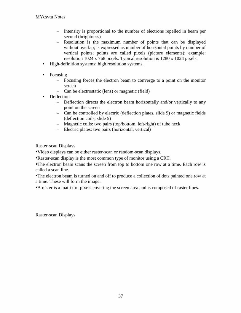
MYcsvtu Notes
37
ndash Intensity is proportional to the number of electrons repelled in beam per
second (brightness)
ndash Resolution is the maximum number of points that can be displayed
without overlap is expressed as number of horizontal points by number of
vertical points points are called pixels (picture elements) example
resolution 1024 x 768 pixels Typical resolution is 1280 x 1024 pixels
bull High-definition systems high resolution systems
bull Focusing
ndash Focusing forces the electron beam to converge to a point on the monitor
screen
ndash Can be electrostatic (lens) or magnetic (field)
bull Deflection
ndash Deflection directs the electron beam horizontally andor vertically to any
point on the screen
ndash Can be controlled by electric (deflection plates slide 9) or magnetic fields
(deflection coils slide 5)
ndash Magnetic coils two pairs (topbottom leftright) of tube neck
ndash Electric plates two pairs (horizontal vertical)
Raster-scan Displays
bullVideo displays can be either raster-scan or random-scan displays
bullRaster-scan display is the most common type of monitor using a CRT
bullThe electron beam scans the screen from top to bottom one row at a time Each row is
called a scan line
bullThe electron beam is turned on and off to produce a collection of dots painted one row at
a time These will form the image
bullA raster is a matrix of pixels covering the screen area and is composed of raster lines
Raster-scan Displays
MYcsvtu Notes
38
Raster-scan Displays
bullThe image is stored in a frame buffer containing the total screen area and where each
memory location corresponds to a pixel
bullIn a monochrome system each bit is 1 or 0 for the corresponding pixel to be on or off
(bitmap)
bullThe display processor scans the frame buffer to turn electron beam onoff depending if
the bit is 1 or 0
bullFor color monitors the frame buffer also contains the color of each pixel (color buffer)
as well as other characteristics of the image (gray scale hellip) 8 bitspixel 0255
(pixmap)
bullDepth of the buffer area is the number of bits per pixel (bit planes) up to 24
bullExamples television panels printers PC monitors (99 of raster-scan)
Raster-scan Displays
bullRefresh rate 24 is a minimum to avoid flicker corresponding to 24 Hz (1 Hz = 1 refresh
per second)
bullCurrent raster-scan displays have a refresh rate of at least 60 frames (60 Hz) per second
up to 120 (120 Hz)
bullUses large memory 640x480 307200 bits 38 kB
bullRefresh procedure
MYcsvtu Notes
39
ndashHorizontal retrace ndash beam returns to left of screen
ndashVertical retrace ndash bean returns to top left corner of screen
ndashInterlaced refresh ndash display first even-numbered lines then odd-numbered lines
permits to see the image in half the time
useful for slow refresh rates (30 Hz shows as 60 Hz)
Random-scan Displays
bullRandom scan systems are also called vector stroke-writing or calligraphic displays
bullThe electron beam directly draws the picture in any specified order
bullA pen plotter is an example of such a system
bullPicture is stored in a display list refresh display file vector file or display program as a
set of line drawing commands
bullRefreshes by scanning the list 30 to 60 times per second
bullMore suited for line-drawing applications such as architecture and manufacturing
Random-scan Displays
bullAdvantages
ndashHigh resolution
ndashEasy animation
ndashRequires little memory
bullDisadvantages
ndashRequires intelligent electron beam (processor controlled)
ndashLimited screen density limited to simple line-based images
ndashLimited color capability
bullImproved in the 1960lsquos by the Direct View Storage Tube (DVST) from Tektronix
Color CRT Monitor
Uses different phosphors a combination of Red Green and Blue to produce any color
Two methods
Random scan uses beam penetration
2 layers (Red Green) phosphors low speed electrons excite Red high speed electrons
excite Green interrmediate speed excite both to get yellow and orange Color is
controlled by electron beam voltage
Only produces a restricted set of colors
Raster scan uses a shadow mask with three electron guns Red Green and Blue (RGB
color model) Color is produced by adjusting the intensity level of each electron beam
Produces a wide range of colors from 8 to several millions
Raster scan
Most common as found in televisions
Beam scanned left to right flicked back to rescan from top to bottom then repeated
Repeated at 30Hz per frame sometimes higher to reduce flicker Interlacing scanning
MYcsvtu Notes
40
odd lines in whole screen then even lines is also used to reduce flicker Can also use
high-persistence phosphor to reduce flicker but causes image smearing especially with
significant animation
Resolution typically 512x512 but high-quality screens are available (and becoming more
common) at up to approximately 1600x1200 pixels Sun workstations have screens of
1192x980 pixels
Black amp white screens can display grayscale by varying the intensity of the electron
beam
Colour is achieved using three electron guns which hit red green or blue phosphors
Combining these colours can produce many others including white (all on) Phosphor
dots focused using a shadow mask - makes colour screens lower resolution than
monochrome
Alternative approach beam penetration Special phosphor glows a different colour
depending on intensity of beam
Colour or intensity at pixel held by computerlsquos video card 1 bitpixel can store offon
information hence only black ampwhite More bitspixel give rise to more colour
possibilities eg 8 bitspixel gives rise to 2^8=256 possible colours at any one time
Random Scan (Directed-beam refresh vector display)
Instead of scanning the whole display sequentially and horizontally the random scan
draws the lines to be displayed directly Screen update at gt30Hz to reduce flicker
Jaggies not found and higher resolutions possible (up to 4096x4096 pixels) Colour
achieved using beam penetration generally of poorer quality Eye strain and fatigue still
a problem and vector displays are more expensive
Direct view storage tube (DVST)
Used a lot in analogue storage oscilloscopes
Similar to random scan crt but image maintained by flood guns - no flicker Can be
incrementally updated but not selectively erased image has to be redrawn on completely
erased screen High resolution (typically 4096x3120 pixels) but low contrast low
brightness and difficulty in displaying colour
What is a Multimedia System
bull A system that involves
ndash generation
ndash representation
ndash storage
ndash transmission
ndash search and retrieval
ndash delivery
MYcsvtu Notes
41
of multimedia information
productionauthoring tools
compression and formats
file system design
networking issues
database management
server design streaming
Multimedia System Architecture
Information management subsystem Presentation Query
Storage subsystem Efficiently stored
amp retrieved
Network subsystem Delivery
Adaptation in Multimedia Systems
bull Multimedia systems can profit a lot from personalization
ndash User behavior
ndash User properties
bull Adaptation
ndash Models
ndash Mechanisms
Multimedia in a mobile environment
MYcsvtu Notes
42
bull Applications
ndash Emergency response systems mobile commerce phone service
entertainment games
What is Sound
A ripple is a pressure wave in water created by an object striking the water
Sound is a pressure wave in air created for example by an object such as a string
or our vocal cords vibrating Dark here represents more pressure light represents
less
MYcsvtu Notes
43
Sine Waves Form Pure Tones
This simple sound wave is a Sine Wave a Pure tone produced by a simple vibration
Sine Wave Sample Tone
This can be represented graphically as shown above
Converting Pressure into Voltage
The pressure wave of sound moves a diaphragm in the microphone which produces a
voltage proportional to the pressure of the sound wave at each instant
Animation
MYcsvtu Notes
44
bull Animation is the rapid display of a sequence of images of 2-D artwork or model
positions in order to create an illusion of movement It is an optical illusion of
motion due to the phenomenon of persistence of vision This could be anything
from a flip book to a motion picture film Animation deals with the generation
sequencing and display a set of images which is called frames to create an effect
of visual change or motion similar to a movie film
bull Animation is used in those instance where videography is not possible
Hardware Requirement For Animation
bull Image Generation Tools amp Devices
bull Computer monitors with image display Capability
Software Requirement For Animation
bull Animation creating software
bull Screen Capture Software
bull Animation Clips
bull Software support For High Resolution
bull Recording amp Playback Capability
bull Transition effect
Early animation
There is no single person that can be considered the creator of the art of animation as
there were several people doing several projects which could be considered various types
of animation all around the same time (Short hand-drawn animation scenes could be
presented with the Phenakistoscope the Zoetrope and other optical toys already in the
early 1800s)
The following is a brief listing on those who are often acknowledged as significant to the
development of animation Note that this list is by no means a comprehensive list of
contributors to early animation
Georges Meacuteliegraves was a creator of special effect films such as A Trip to the Moon He
used many techniques ndash one of which was to stop the camera rolling change something
in the scene and then continue rolling the film This is a very similar idea to that of stop-
motion animation Meacuteliegraves accidentally happened upon the technique when his camera
broke down while shooting a bus driving by When the camera was fixed a horse
happened to be passing by just as Meacuteliegraves continued to film The result was that the bus
appeared to change into a horse
MYcsvtu Notes
45
Fantasmagorie by Emile Cohl 1908
Eacutemile Cohl began drawing cartoon strips and created a film in 1908 called
Fantasmagorie The film largely consisted of a stick figure moving about and
encountering all manner of morphing objects such as a wine bottle that transforms into a
flower There were also sections of live action where the animatorlsquos hands would enter
the scene The film was created by drawing each frame on paper and then shooting each
frame onto negative film which gave the picture a blackboard look
Winsor McCay created detailed animations that required a team of artists and painstaking
attention for detail Each frame was drawn on paper requiring backgrounds to be
redrawn as well characters to be animated His films such as Gertie the Dinosaur (1914)
and The Sinking of the Lusitania (1918) were of an impressive scale although The
Sinking of the Lusitania used cels
In 1919 Otto Messmer created the character of Felix the cat for Pat Sullivans animation
studios The importance of Felix lies in the characters strong personality created largely
through gesture and actions
Animation techniques
Animation techniques are incredibly varied and difficult to categorize Techniques are
often related or combined The following is a brief on common types of animation
Again this list is by no means comprehensive
Traditional animation
An example of traditional animation a horse animated by rotoscoping from Edweard
Muybridges 19th century photos
Main article Traditional animation
MYcsvtu Notes
46
Also called cel animation the frames of a traditionally animated movie are hand-drawn
The drawings are traced or copied onto transparent acetate sheets called cels which are
then placed over a painted background and photographed one by one on a rostrum
camera Nowadays the use of cels (and cameras) is mostly obsolete since the drawings
are scanned into computers and digitally transferred directly to 35 mm film The look
of traditional cel animation is still preserved and the character animators work has
remained essentially the same over the past 70 years Because of the digital influence
over modern cel animation it is also known as tradigital animation
Examples The Lion King Spirited Away Les Triplettes de Belleville
Full animation The most common style in animation known for its realistic and often very detailed art
Examples All Disney feature length animated films The Secret of NIMH The Iron Giant
Limited animation A cheaper process of making animated cartoons that does not follow a realistic
approach
Examples The Flintstones Yellow Submarine
Rubber hose The characters are usually cartoony and the animators have a lot of artistic freedom as
rubber hose animations dont have to follow the laws of physics and anatomy in the same
degree as the other main styles in animation
Examples Early Mickey Mouse cartoons Ren and Stimpy Popeye
Rotoscoping A technique where animators trace live action movement frame by frame for use in
animated films
Examples Gullivers Travels American Pop
Stop motion
Stop-motion animation is any type of animation which requires the animator to physically
alter the scene shoot a frame again alter the scene and shoot a frame and so on to create
the animation There are many different types of stop-motion animation some noteable
examples are listed below
Clay animation
MYcsvtu Notes
47
A clay animation scene from a TV commercial
Often abbreviated to claymation this is a type of stop-motion animation using
figures made of clay or a similar malleable material The figures may have an
armature or wire frame inside of them similar to puppet animation (below)
Alternatively the figures may be made entirely of clay such as in the films of
Bruce Bickford where clay creatures morph into a variety of different shapes
Examples Wallace and Gromit Dimensions of Dialogue by Jan Švankmajer The
Amazing Mr Bickford The Trap Door
Cutout animation In this type of stop-motion animation the animation is formed by moving 2-
dimensional pieces of material such as paper or cloth
Examples the animated sequences of Monty Pythons Flying Circus (often
referred to as Dada animation named after the Dada art movement[citation needed]
)
Tale of Tales early episodes of South Park
Silhouette animation A type of cutout animation where the viewer only sees black silhouettes
Example The Adventures of Prince Achmed the worlds oldest surviving
animated feature film from 1926
Graphic animation
Model animation In this form of animation model animated characters interact with and are a part
of the live-action world
Examples The films of Ray Harryhausen (Jason and the Argonauts) and Willis
OBrien (King Kong)
Go motion
Object animation
Pixilation Examples Neighbours
Puppet animation Puppet animation typically involves puppet figures interacting with each other in
a constructed environment in contrast to the real-world interaction in model
MYcsvtu Notes
48
animation (above) The puppets generally have an armature inside of them to
keep them still and steady as well as constraining them to move at particular
joints
Examples The Nightmare Before Christmas Robot Chicken The Tale of the Fox
Brickfilm
Puppetoon
Computer animation
A short gif animation
Like stop motion computer animation encompasses a variety of techniques the unifying
idea being that the animation is created digitally on a computer
2D animation Figures are created andor edited on the computer using 2D bitmap graphics or
created and edited using 2D vector graphics This includes automated
computerized versions of traditional animation techniques such as of tweening
morphing onion skinning and interpolated rotoscoping
Examples A Scanner Darkly Jib Jab
Analog computer animation
Flash animation
PowerPoint animation
A completely synthetic computer-generated scene
3D animation
MYcsvtu Notes
49
Figures are created in the computer using polygons To allow these meshes to
move they are given a digital armature (sculpture) This process is called rigging
Various other techniques can be applied such as mathematical functions
(gravity) simulated fur or hair effects such as fire and water and the use of
motion capture to name but a few
Examples The Incredibles Shrek
Cel-shaded animation
Morph target animation
Skeletal animation
Motion capture
Crowd simulation
Less common techniques
Drawn on film animation A technique where footage is produced by creating the
images directly on film stock
Paint-on-glass animationA technique for making animated films by manipulating slow-
drying oil paints on sheets of glass
Pinscreen animation Makes use of a screen filled with movable pins which can be
moved in or out by pressing an object onto the screen The screen is lit from the side so
that the pins cast shadows The technique has been used to create animated films with a
range of textural effects difficult to achieve with traditional cel animation
Sand animation Sand is moved around on a backlighted or frontlighted piece of glass to
create each frame for an animated film
Multimedia
Multimedia (Lat Multum + Medium) is media that uses multiple forms of information
content and information processing (eg text audio graphics animation video
interactivity) to inform or entertain the (user) audience Multimedia also refers to the use
of (but not limited to) electronic media to store and experience multimedia content
Multimedia is similar to traditional mixed media in fine art but with a broader scope The
term rich media is synonymous for interactive multimedia
Categorization
Multimedia may be broadly divided into linear and non-linear categories Linear active
content progresses without any navigation control for the viewer such as a cinema
presentation Non-linear content offers user interactivity to control progress as used with
MYcsvtu Notes
50
a computer game or used in self-paced computer based training Non-linear content is
also known as hypermedia content
Multimedia presentations can be live or recorded A recorded presentation may allow
interactivity via a navigation system A live multimedia presentation may allow
interactivity via interaction with the presenter or performer
There are 2 basic way to represent some information
Unimedium Presentation
Multimedia Presentation
In case of computer system the commonly used medioa for the purpose of storage
access and transmission of information are
bull Text
bull Graphics
bull Animation
bull Audio
bull Video
Multimedia Computer System require
bull Faster CPU
bull Larger Storage Devices
bull Larger Main Memory
bull Good Graphics Terminal
bull IO devices required to play an audio associated with the program
Transmission Mode
bull Asynchronous
bull Synchronous
bull Isochronous
MYcsvtu Notes
41
of multimedia information
productionauthoring tools
compression and formats
file system design
networking issues
database management
server design streaming
Multimedia System Architecture
Information management subsystem Presentation Query
Storage subsystem Efficiently stored
amp retrieved
Network subsystem Delivery
Adaptation in Multimedia Systems
bull Multimedia systems can profit a lot from personalization
ndash User behavior
ndash User properties
bull Adaptation
ndash Models
ndash Mechanisms
Multimedia in a mobile environment
MYcsvtu Notes
42
bull Applications
ndash Emergency response systems mobile commerce phone service
entertainment games
What is Sound
A ripple is a pressure wave in water created by an object striking the water
Sound is a pressure wave in air created for example by an object such as a string
or our vocal cords vibrating Dark here represents more pressure light represents
less
MYcsvtu Notes
43
Sine Waves Form Pure Tones
This simple sound wave is a Sine Wave a Pure tone produced by a simple vibration
Sine Wave Sample Tone
This can be represented graphically as shown above
Converting Pressure into Voltage
The pressure wave of sound moves a diaphragm in the microphone which produces a
voltage proportional to the pressure of the sound wave at each instant
Animation
MYcsvtu Notes
44
bull Animation is the rapid display of a sequence of images of 2-D artwork or model
positions in order to create an illusion of movement It is an optical illusion of
motion due to the phenomenon of persistence of vision This could be anything
from a flip book to a motion picture film Animation deals with the generation
sequencing and display a set of images which is called frames to create an effect
of visual change or motion similar to a movie film
bull Animation is used in those instance where videography is not possible
Hardware Requirement For Animation
bull Image Generation Tools amp Devices
bull Computer monitors with image display Capability
Software Requirement For Animation
bull Animation creating software
bull Screen Capture Software
bull Animation Clips
bull Software support For High Resolution
bull Recording amp Playback Capability
bull Transition effect
Early animation
There is no single person that can be considered the creator of the art of animation as
there were several people doing several projects which could be considered various types
of animation all around the same time (Short hand-drawn animation scenes could be
presented with the Phenakistoscope the Zoetrope and other optical toys already in the
early 1800s)
The following is a brief listing on those who are often acknowledged as significant to the
development of animation Note that this list is by no means a comprehensive list of
contributors to early animation
Georges Meacuteliegraves was a creator of special effect films such as A Trip to the Moon He
used many techniques ndash one of which was to stop the camera rolling change something
in the scene and then continue rolling the film This is a very similar idea to that of stop-
motion animation Meacuteliegraves accidentally happened upon the technique when his camera
broke down while shooting a bus driving by When the camera was fixed a horse
happened to be passing by just as Meacuteliegraves continued to film The result was that the bus
appeared to change into a horse
MYcsvtu Notes
45
Fantasmagorie by Emile Cohl 1908
Eacutemile Cohl began drawing cartoon strips and created a film in 1908 called
Fantasmagorie The film largely consisted of a stick figure moving about and
encountering all manner of morphing objects such as a wine bottle that transforms into a
flower There were also sections of live action where the animatorlsquos hands would enter
the scene The film was created by drawing each frame on paper and then shooting each
frame onto negative film which gave the picture a blackboard look
Winsor McCay created detailed animations that required a team of artists and painstaking
attention for detail Each frame was drawn on paper requiring backgrounds to be
redrawn as well characters to be animated His films such as Gertie the Dinosaur (1914)
and The Sinking of the Lusitania (1918) were of an impressive scale although The
Sinking of the Lusitania used cels
In 1919 Otto Messmer created the character of Felix the cat for Pat Sullivans animation
studios The importance of Felix lies in the characters strong personality created largely
through gesture and actions
Animation techniques
Animation techniques are incredibly varied and difficult to categorize Techniques are
often related or combined The following is a brief on common types of animation
Again this list is by no means comprehensive
Traditional animation
An example of traditional animation a horse animated by rotoscoping from Edweard
Muybridges 19th century photos
Main article Traditional animation
MYcsvtu Notes
46
Also called cel animation the frames of a traditionally animated movie are hand-drawn
The drawings are traced or copied onto transparent acetate sheets called cels which are
then placed over a painted background and photographed one by one on a rostrum
camera Nowadays the use of cels (and cameras) is mostly obsolete since the drawings
are scanned into computers and digitally transferred directly to 35 mm film The look
of traditional cel animation is still preserved and the character animators work has
remained essentially the same over the past 70 years Because of the digital influence
over modern cel animation it is also known as tradigital animation
Examples The Lion King Spirited Away Les Triplettes de Belleville
Full animation The most common style in animation known for its realistic and often very detailed art
Examples All Disney feature length animated films The Secret of NIMH The Iron Giant
Limited animation A cheaper process of making animated cartoons that does not follow a realistic
approach
Examples The Flintstones Yellow Submarine
Rubber hose The characters are usually cartoony and the animators have a lot of artistic freedom as
rubber hose animations dont have to follow the laws of physics and anatomy in the same
degree as the other main styles in animation
Examples Early Mickey Mouse cartoons Ren and Stimpy Popeye
Rotoscoping A technique where animators trace live action movement frame by frame for use in
animated films
Examples Gullivers Travels American Pop
Stop motion
Stop-motion animation is any type of animation which requires the animator to physically
alter the scene shoot a frame again alter the scene and shoot a frame and so on to create
the animation There are many different types of stop-motion animation some noteable
examples are listed below
Clay animation
MYcsvtu Notes
47
A clay animation scene from a TV commercial
Often abbreviated to claymation this is a type of stop-motion animation using
figures made of clay or a similar malleable material The figures may have an
armature or wire frame inside of them similar to puppet animation (below)
Alternatively the figures may be made entirely of clay such as in the films of
Bruce Bickford where clay creatures morph into a variety of different shapes
Examples Wallace and Gromit Dimensions of Dialogue by Jan Švankmajer The
Amazing Mr Bickford The Trap Door
Cutout animation In this type of stop-motion animation the animation is formed by moving 2-
dimensional pieces of material such as paper or cloth
Examples the animated sequences of Monty Pythons Flying Circus (often
referred to as Dada animation named after the Dada art movement[citation needed]
)
Tale of Tales early episodes of South Park
Silhouette animation A type of cutout animation where the viewer only sees black silhouettes
Example The Adventures of Prince Achmed the worlds oldest surviving
animated feature film from 1926
Graphic animation
Model animation In this form of animation model animated characters interact with and are a part
of the live-action world
Examples The films of Ray Harryhausen (Jason and the Argonauts) and Willis
OBrien (King Kong)
Go motion
Object animation
Pixilation Examples Neighbours
Puppet animation Puppet animation typically involves puppet figures interacting with each other in
a constructed environment in contrast to the real-world interaction in model
MYcsvtu Notes
48
animation (above) The puppets generally have an armature inside of them to
keep them still and steady as well as constraining them to move at particular
joints
Examples The Nightmare Before Christmas Robot Chicken The Tale of the Fox
Brickfilm
Puppetoon
Computer animation
A short gif animation
Like stop motion computer animation encompasses a variety of techniques the unifying
idea being that the animation is created digitally on a computer
2D animation Figures are created andor edited on the computer using 2D bitmap graphics or
created and edited using 2D vector graphics This includes automated
computerized versions of traditional animation techniques such as of tweening
morphing onion skinning and interpolated rotoscoping
Examples A Scanner Darkly Jib Jab
Analog computer animation
Flash animation
PowerPoint animation
A completely synthetic computer-generated scene
3D animation
MYcsvtu Notes
49
Figures are created in the computer using polygons To allow these meshes to
move they are given a digital armature (sculpture) This process is called rigging
Various other techniques can be applied such as mathematical functions
(gravity) simulated fur or hair effects such as fire and water and the use of
motion capture to name but a few
Examples The Incredibles Shrek
Cel-shaded animation
Morph target animation
Skeletal animation
Motion capture
Crowd simulation
Less common techniques
Drawn on film animation A technique where footage is produced by creating the
images directly on film stock
Paint-on-glass animationA technique for making animated films by manipulating slow-
drying oil paints on sheets of glass
Pinscreen animation Makes use of a screen filled with movable pins which can be
moved in or out by pressing an object onto the screen The screen is lit from the side so
that the pins cast shadows The technique has been used to create animated films with a
range of textural effects difficult to achieve with traditional cel animation
Sand animation Sand is moved around on a backlighted or frontlighted piece of glass to
create each frame for an animated film
Multimedia
Multimedia (Lat Multum + Medium) is media that uses multiple forms of information
content and information processing (eg text audio graphics animation video
interactivity) to inform or entertain the (user) audience Multimedia also refers to the use
of (but not limited to) electronic media to store and experience multimedia content
Multimedia is similar to traditional mixed media in fine art but with a broader scope The
term rich media is synonymous for interactive multimedia
Categorization
Multimedia may be broadly divided into linear and non-linear categories Linear active
content progresses without any navigation control for the viewer such as a cinema
presentation Non-linear content offers user interactivity to control progress as used with
MYcsvtu Notes
50
a computer game or used in self-paced computer based training Non-linear content is
also known as hypermedia content
Multimedia presentations can be live or recorded A recorded presentation may allow
interactivity via a navigation system A live multimedia presentation may allow
interactivity via interaction with the presenter or performer
There are 2 basic way to represent some information
Unimedium Presentation
Multimedia Presentation
In case of computer system the commonly used medioa for the purpose of storage
access and transmission of information are
bull Text
bull Graphics
bull Animation
bull Audio
bull Video
Multimedia Computer System require
bull Faster CPU
bull Larger Storage Devices
bull Larger Main Memory
bull Good Graphics Terminal
bull IO devices required to play an audio associated with the program
Transmission Mode
bull Asynchronous
bull Synchronous
bull Isochronous
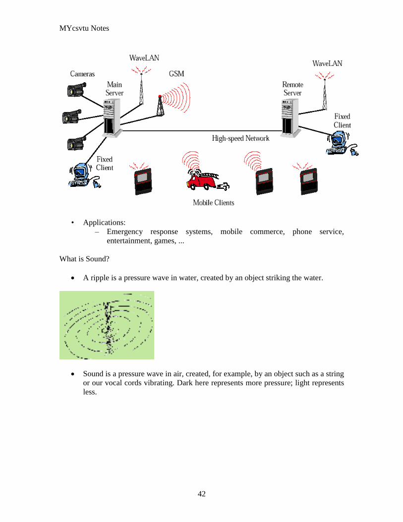
MYcsvtu Notes
42
bull Applications
ndash Emergency response systems mobile commerce phone service
entertainment games
What is Sound
A ripple is a pressure wave in water created by an object striking the water
Sound is a pressure wave in air created for example by an object such as a string
or our vocal cords vibrating Dark here represents more pressure light represents
less
MYcsvtu Notes
43
Sine Waves Form Pure Tones
This simple sound wave is a Sine Wave a Pure tone produced by a simple vibration
Sine Wave Sample Tone
This can be represented graphically as shown above
Converting Pressure into Voltage
The pressure wave of sound moves a diaphragm in the microphone which produces a
voltage proportional to the pressure of the sound wave at each instant
Animation
MYcsvtu Notes
44
bull Animation is the rapid display of a sequence of images of 2-D artwork or model
positions in order to create an illusion of movement It is an optical illusion of
motion due to the phenomenon of persistence of vision This could be anything
from a flip book to a motion picture film Animation deals with the generation
sequencing and display a set of images which is called frames to create an effect
of visual change or motion similar to a movie film
bull Animation is used in those instance where videography is not possible
Hardware Requirement For Animation
bull Image Generation Tools amp Devices
bull Computer monitors with image display Capability
Software Requirement For Animation
bull Animation creating software
bull Screen Capture Software
bull Animation Clips
bull Software support For High Resolution
bull Recording amp Playback Capability
bull Transition effect
Early animation
There is no single person that can be considered the creator of the art of animation as
there were several people doing several projects which could be considered various types
of animation all around the same time (Short hand-drawn animation scenes could be
presented with the Phenakistoscope the Zoetrope and other optical toys already in the
early 1800s)
The following is a brief listing on those who are often acknowledged as significant to the
development of animation Note that this list is by no means a comprehensive list of
contributors to early animation
Georges Meacuteliegraves was a creator of special effect films such as A Trip to the Moon He
used many techniques ndash one of which was to stop the camera rolling change something
in the scene and then continue rolling the film This is a very similar idea to that of stop-
motion animation Meacuteliegraves accidentally happened upon the technique when his camera
broke down while shooting a bus driving by When the camera was fixed a horse
happened to be passing by just as Meacuteliegraves continued to film The result was that the bus
appeared to change into a horse
MYcsvtu Notes
45
Fantasmagorie by Emile Cohl 1908
Eacutemile Cohl began drawing cartoon strips and created a film in 1908 called
Fantasmagorie The film largely consisted of a stick figure moving about and
encountering all manner of morphing objects such as a wine bottle that transforms into a
flower There were also sections of live action where the animatorlsquos hands would enter
the scene The film was created by drawing each frame on paper and then shooting each
frame onto negative film which gave the picture a blackboard look
Winsor McCay created detailed animations that required a team of artists and painstaking
attention for detail Each frame was drawn on paper requiring backgrounds to be
redrawn as well characters to be animated His films such as Gertie the Dinosaur (1914)
and The Sinking of the Lusitania (1918) were of an impressive scale although The
Sinking of the Lusitania used cels
In 1919 Otto Messmer created the character of Felix the cat for Pat Sullivans animation
studios The importance of Felix lies in the characters strong personality created largely
through gesture and actions
Animation techniques
Animation techniques are incredibly varied and difficult to categorize Techniques are
often related or combined The following is a brief on common types of animation
Again this list is by no means comprehensive
Traditional animation
An example of traditional animation a horse animated by rotoscoping from Edweard
Muybridges 19th century photos
Main article Traditional animation
MYcsvtu Notes
46
Also called cel animation the frames of a traditionally animated movie are hand-drawn
The drawings are traced or copied onto transparent acetate sheets called cels which are
then placed over a painted background and photographed one by one on a rostrum
camera Nowadays the use of cels (and cameras) is mostly obsolete since the drawings
are scanned into computers and digitally transferred directly to 35 mm film The look
of traditional cel animation is still preserved and the character animators work has
remained essentially the same over the past 70 years Because of the digital influence
over modern cel animation it is also known as tradigital animation
Examples The Lion King Spirited Away Les Triplettes de Belleville
Full animation The most common style in animation known for its realistic and often very detailed art
Examples All Disney feature length animated films The Secret of NIMH The Iron Giant
Limited animation A cheaper process of making animated cartoons that does not follow a realistic
approach
Examples The Flintstones Yellow Submarine
Rubber hose The characters are usually cartoony and the animators have a lot of artistic freedom as
rubber hose animations dont have to follow the laws of physics and anatomy in the same
degree as the other main styles in animation
Examples Early Mickey Mouse cartoons Ren and Stimpy Popeye
Rotoscoping A technique where animators trace live action movement frame by frame for use in
animated films
Examples Gullivers Travels American Pop
Stop motion
Stop-motion animation is any type of animation which requires the animator to physically
alter the scene shoot a frame again alter the scene and shoot a frame and so on to create
the animation There are many different types of stop-motion animation some noteable
examples are listed below
Clay animation
MYcsvtu Notes
47
A clay animation scene from a TV commercial
Often abbreviated to claymation this is a type of stop-motion animation using
figures made of clay or a similar malleable material The figures may have an
armature or wire frame inside of them similar to puppet animation (below)
Alternatively the figures may be made entirely of clay such as in the films of
Bruce Bickford where clay creatures morph into a variety of different shapes
Examples Wallace and Gromit Dimensions of Dialogue by Jan Švankmajer The
Amazing Mr Bickford The Trap Door
Cutout animation In this type of stop-motion animation the animation is formed by moving 2-
dimensional pieces of material such as paper or cloth
Examples the animated sequences of Monty Pythons Flying Circus (often
referred to as Dada animation named after the Dada art movement[citation needed]
)
Tale of Tales early episodes of South Park
Silhouette animation A type of cutout animation where the viewer only sees black silhouettes
Example The Adventures of Prince Achmed the worlds oldest surviving
animated feature film from 1926
Graphic animation
Model animation In this form of animation model animated characters interact with and are a part
of the live-action world
Examples The films of Ray Harryhausen (Jason and the Argonauts) and Willis
OBrien (King Kong)
Go motion
Object animation
Pixilation Examples Neighbours
Puppet animation Puppet animation typically involves puppet figures interacting with each other in
a constructed environment in contrast to the real-world interaction in model
MYcsvtu Notes
48
animation (above) The puppets generally have an armature inside of them to
keep them still and steady as well as constraining them to move at particular
joints
Examples The Nightmare Before Christmas Robot Chicken The Tale of the Fox
Brickfilm
Puppetoon
Computer animation
A short gif animation
Like stop motion computer animation encompasses a variety of techniques the unifying
idea being that the animation is created digitally on a computer
2D animation Figures are created andor edited on the computer using 2D bitmap graphics or
created and edited using 2D vector graphics This includes automated
computerized versions of traditional animation techniques such as of tweening
morphing onion skinning and interpolated rotoscoping
Examples A Scanner Darkly Jib Jab
Analog computer animation
Flash animation
PowerPoint animation
A completely synthetic computer-generated scene
3D animation
MYcsvtu Notes
49
Figures are created in the computer using polygons To allow these meshes to
move they are given a digital armature (sculpture) This process is called rigging
Various other techniques can be applied such as mathematical functions
(gravity) simulated fur or hair effects such as fire and water and the use of
motion capture to name but a few
Examples The Incredibles Shrek
Cel-shaded animation
Morph target animation
Skeletal animation
Motion capture
Crowd simulation
Less common techniques
Drawn on film animation A technique where footage is produced by creating the
images directly on film stock
Paint-on-glass animationA technique for making animated films by manipulating slow-
drying oil paints on sheets of glass
Pinscreen animation Makes use of a screen filled with movable pins which can be
moved in or out by pressing an object onto the screen The screen is lit from the side so
that the pins cast shadows The technique has been used to create animated films with a
range of textural effects difficult to achieve with traditional cel animation
Sand animation Sand is moved around on a backlighted or frontlighted piece of glass to
create each frame for an animated film
Multimedia
Multimedia (Lat Multum + Medium) is media that uses multiple forms of information
content and information processing (eg text audio graphics animation video
interactivity) to inform or entertain the (user) audience Multimedia also refers to the use
of (but not limited to) electronic media to store and experience multimedia content
Multimedia is similar to traditional mixed media in fine art but with a broader scope The
term rich media is synonymous for interactive multimedia
Categorization
Multimedia may be broadly divided into linear and non-linear categories Linear active
content progresses without any navigation control for the viewer such as a cinema
presentation Non-linear content offers user interactivity to control progress as used with
MYcsvtu Notes
50
a computer game or used in self-paced computer based training Non-linear content is
also known as hypermedia content
Multimedia presentations can be live or recorded A recorded presentation may allow
interactivity via a navigation system A live multimedia presentation may allow
interactivity via interaction with the presenter or performer
There are 2 basic way to represent some information
Unimedium Presentation
Multimedia Presentation
In case of computer system the commonly used medioa for the purpose of storage
access and transmission of information are
bull Text
bull Graphics
bull Animation
bull Audio
bull Video
Multimedia Computer System require
bull Faster CPU
bull Larger Storage Devices
bull Larger Main Memory
bull Good Graphics Terminal
bull IO devices required to play an audio associated with the program
Transmission Mode
bull Asynchronous
bull Synchronous
bull Isochronous
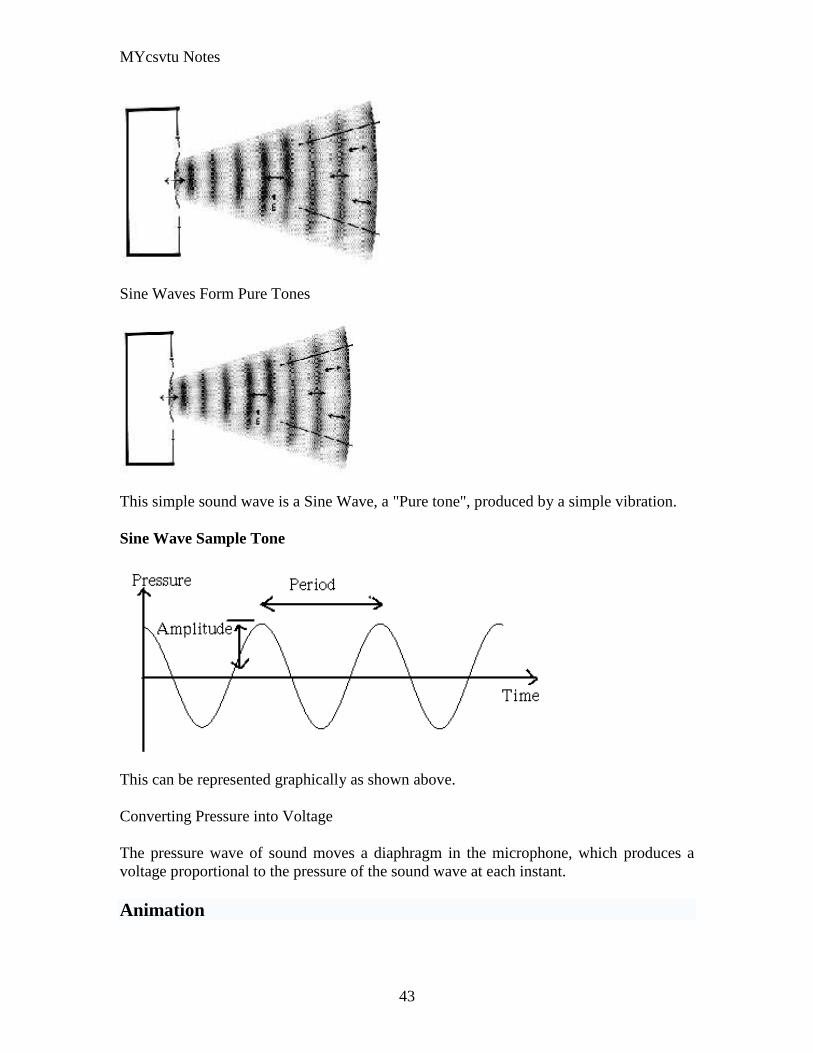
MYcsvtu Notes
43
Sine Waves Form Pure Tones
This simple sound wave is a Sine Wave a Pure tone produced by a simple vibration
Sine Wave Sample Tone
This can be represented graphically as shown above
Converting Pressure into Voltage
The pressure wave of sound moves a diaphragm in the microphone which produces a
voltage proportional to the pressure of the sound wave at each instant
Animation
MYcsvtu Notes
44
bull Animation is the rapid display of a sequence of images of 2-D artwork or model
positions in order to create an illusion of movement It is an optical illusion of
motion due to the phenomenon of persistence of vision This could be anything
from a flip book to a motion picture film Animation deals with the generation
sequencing and display a set of images which is called frames to create an effect
of visual change or motion similar to a movie film
bull Animation is used in those instance where videography is not possible
Hardware Requirement For Animation
bull Image Generation Tools amp Devices
bull Computer monitors with image display Capability
Software Requirement For Animation
bull Animation creating software
bull Screen Capture Software
bull Animation Clips
bull Software support For High Resolution
bull Recording amp Playback Capability
bull Transition effect
Early animation
There is no single person that can be considered the creator of the art of animation as
there were several people doing several projects which could be considered various types
of animation all around the same time (Short hand-drawn animation scenes could be
presented with the Phenakistoscope the Zoetrope and other optical toys already in the
early 1800s)
The following is a brief listing on those who are often acknowledged as significant to the
development of animation Note that this list is by no means a comprehensive list of
contributors to early animation
Georges Meacuteliegraves was a creator of special effect films such as A Trip to the Moon He
used many techniques ndash one of which was to stop the camera rolling change something
in the scene and then continue rolling the film This is a very similar idea to that of stop-
motion animation Meacuteliegraves accidentally happened upon the technique when his camera
broke down while shooting a bus driving by When the camera was fixed a horse
happened to be passing by just as Meacuteliegraves continued to film The result was that the bus
appeared to change into a horse
MYcsvtu Notes
45
Fantasmagorie by Emile Cohl 1908
Eacutemile Cohl began drawing cartoon strips and created a film in 1908 called
Fantasmagorie The film largely consisted of a stick figure moving about and
encountering all manner of morphing objects such as a wine bottle that transforms into a
flower There were also sections of live action where the animatorlsquos hands would enter
the scene The film was created by drawing each frame on paper and then shooting each
frame onto negative film which gave the picture a blackboard look
Winsor McCay created detailed animations that required a team of artists and painstaking
attention for detail Each frame was drawn on paper requiring backgrounds to be
redrawn as well characters to be animated His films such as Gertie the Dinosaur (1914)
and The Sinking of the Lusitania (1918) were of an impressive scale although The
Sinking of the Lusitania used cels
In 1919 Otto Messmer created the character of Felix the cat for Pat Sullivans animation
studios The importance of Felix lies in the characters strong personality created largely
through gesture and actions
Animation techniques
Animation techniques are incredibly varied and difficult to categorize Techniques are
often related or combined The following is a brief on common types of animation
Again this list is by no means comprehensive
Traditional animation
An example of traditional animation a horse animated by rotoscoping from Edweard
Muybridges 19th century photos
Main article Traditional animation
MYcsvtu Notes
46
Also called cel animation the frames of a traditionally animated movie are hand-drawn
The drawings are traced or copied onto transparent acetate sheets called cels which are
then placed over a painted background and photographed one by one on a rostrum
camera Nowadays the use of cels (and cameras) is mostly obsolete since the drawings
are scanned into computers and digitally transferred directly to 35 mm film The look
of traditional cel animation is still preserved and the character animators work has
remained essentially the same over the past 70 years Because of the digital influence
over modern cel animation it is also known as tradigital animation
Examples The Lion King Spirited Away Les Triplettes de Belleville
Full animation The most common style in animation known for its realistic and often very detailed art
Examples All Disney feature length animated films The Secret of NIMH The Iron Giant
Limited animation A cheaper process of making animated cartoons that does not follow a realistic
approach
Examples The Flintstones Yellow Submarine
Rubber hose The characters are usually cartoony and the animators have a lot of artistic freedom as
rubber hose animations dont have to follow the laws of physics and anatomy in the same
degree as the other main styles in animation
Examples Early Mickey Mouse cartoons Ren and Stimpy Popeye
Rotoscoping A technique where animators trace live action movement frame by frame for use in
animated films
Examples Gullivers Travels American Pop
Stop motion
Stop-motion animation is any type of animation which requires the animator to physically
alter the scene shoot a frame again alter the scene and shoot a frame and so on to create
the animation There are many different types of stop-motion animation some noteable
examples are listed below
Clay animation
MYcsvtu Notes
47
A clay animation scene from a TV commercial
Often abbreviated to claymation this is a type of stop-motion animation using
figures made of clay or a similar malleable material The figures may have an
armature or wire frame inside of them similar to puppet animation (below)
Alternatively the figures may be made entirely of clay such as in the films of
Bruce Bickford where clay creatures morph into a variety of different shapes
Examples Wallace and Gromit Dimensions of Dialogue by Jan Švankmajer The
Amazing Mr Bickford The Trap Door
Cutout animation In this type of stop-motion animation the animation is formed by moving 2-
dimensional pieces of material such as paper or cloth
Examples the animated sequences of Monty Pythons Flying Circus (often
referred to as Dada animation named after the Dada art movement[citation needed]
)
Tale of Tales early episodes of South Park
Silhouette animation A type of cutout animation where the viewer only sees black silhouettes
Example The Adventures of Prince Achmed the worlds oldest surviving
animated feature film from 1926
Graphic animation
Model animation In this form of animation model animated characters interact with and are a part
of the live-action world
Examples The films of Ray Harryhausen (Jason and the Argonauts) and Willis
OBrien (King Kong)
Go motion
Object animation
Pixilation Examples Neighbours
Puppet animation Puppet animation typically involves puppet figures interacting with each other in
a constructed environment in contrast to the real-world interaction in model
MYcsvtu Notes
48
animation (above) The puppets generally have an armature inside of them to
keep them still and steady as well as constraining them to move at particular
joints
Examples The Nightmare Before Christmas Robot Chicken The Tale of the Fox
Brickfilm
Puppetoon
Computer animation
A short gif animation
Like stop motion computer animation encompasses a variety of techniques the unifying
idea being that the animation is created digitally on a computer
2D animation Figures are created andor edited on the computer using 2D bitmap graphics or
created and edited using 2D vector graphics This includes automated
computerized versions of traditional animation techniques such as of tweening
morphing onion skinning and interpolated rotoscoping
Examples A Scanner Darkly Jib Jab
Analog computer animation
Flash animation
PowerPoint animation
A completely synthetic computer-generated scene
3D animation
MYcsvtu Notes
49
Figures are created in the computer using polygons To allow these meshes to
move they are given a digital armature (sculpture) This process is called rigging
Various other techniques can be applied such as mathematical functions
(gravity) simulated fur or hair effects such as fire and water and the use of
motion capture to name but a few
Examples The Incredibles Shrek
Cel-shaded animation
Morph target animation
Skeletal animation
Motion capture
Crowd simulation
Less common techniques
Drawn on film animation A technique where footage is produced by creating the
images directly on film stock
Paint-on-glass animationA technique for making animated films by manipulating slow-
drying oil paints on sheets of glass
Pinscreen animation Makes use of a screen filled with movable pins which can be
moved in or out by pressing an object onto the screen The screen is lit from the side so
that the pins cast shadows The technique has been used to create animated films with a
range of textural effects difficult to achieve with traditional cel animation
Sand animation Sand is moved around on a backlighted or frontlighted piece of glass to
create each frame for an animated film
Multimedia
Multimedia (Lat Multum + Medium) is media that uses multiple forms of information
content and information processing (eg text audio graphics animation video
interactivity) to inform or entertain the (user) audience Multimedia also refers to the use
of (but not limited to) electronic media to store and experience multimedia content
Multimedia is similar to traditional mixed media in fine art but with a broader scope The
term rich media is synonymous for interactive multimedia
Categorization
Multimedia may be broadly divided into linear and non-linear categories Linear active
content progresses without any navigation control for the viewer such as a cinema
presentation Non-linear content offers user interactivity to control progress as used with
MYcsvtu Notes
50
a computer game or used in self-paced computer based training Non-linear content is
also known as hypermedia content
Multimedia presentations can be live or recorded A recorded presentation may allow
interactivity via a navigation system A live multimedia presentation may allow
interactivity via interaction with the presenter or performer
There are 2 basic way to represent some information
Unimedium Presentation
Multimedia Presentation
In case of computer system the commonly used medioa for the purpose of storage
access and transmission of information are
bull Text
bull Graphics
bull Animation
bull Audio
bull Video
Multimedia Computer System require
bull Faster CPU
bull Larger Storage Devices
bull Larger Main Memory
bull Good Graphics Terminal
bull IO devices required to play an audio associated with the program
Transmission Mode
bull Asynchronous
bull Synchronous
bull Isochronous
MYcsvtu Notes
44
bull Animation is the rapid display of a sequence of images of 2-D artwork or model
positions in order to create an illusion of movement It is an optical illusion of
motion due to the phenomenon of persistence of vision This could be anything
from a flip book to a motion picture film Animation deals with the generation
sequencing and display a set of images which is called frames to create an effect
of visual change or motion similar to a movie film
bull Animation is used in those instance where videography is not possible
Hardware Requirement For Animation
bull Image Generation Tools amp Devices
bull Computer monitors with image display Capability
Software Requirement For Animation
bull Animation creating software
bull Screen Capture Software
bull Animation Clips
bull Software support For High Resolution
bull Recording amp Playback Capability
bull Transition effect
Early animation
There is no single person that can be considered the creator of the art of animation as
there were several people doing several projects which could be considered various types
of animation all around the same time (Short hand-drawn animation scenes could be
presented with the Phenakistoscope the Zoetrope and other optical toys already in the
early 1800s)
The following is a brief listing on those who are often acknowledged as significant to the
development of animation Note that this list is by no means a comprehensive list of
contributors to early animation
Georges Meacuteliegraves was a creator of special effect films such as A Trip to the Moon He
used many techniques ndash one of which was to stop the camera rolling change something
in the scene and then continue rolling the film This is a very similar idea to that of stop-
motion animation Meacuteliegraves accidentally happened upon the technique when his camera
broke down while shooting a bus driving by When the camera was fixed a horse
happened to be passing by just as Meacuteliegraves continued to film The result was that the bus
appeared to change into a horse
MYcsvtu Notes
45
Fantasmagorie by Emile Cohl 1908
Eacutemile Cohl began drawing cartoon strips and created a film in 1908 called
Fantasmagorie The film largely consisted of a stick figure moving about and
encountering all manner of morphing objects such as a wine bottle that transforms into a
flower There were also sections of live action where the animatorlsquos hands would enter
the scene The film was created by drawing each frame on paper and then shooting each
frame onto negative film which gave the picture a blackboard look
Winsor McCay created detailed animations that required a team of artists and painstaking
attention for detail Each frame was drawn on paper requiring backgrounds to be
redrawn as well characters to be animated His films such as Gertie the Dinosaur (1914)
and The Sinking of the Lusitania (1918) were of an impressive scale although The
Sinking of the Lusitania used cels
In 1919 Otto Messmer created the character of Felix the cat for Pat Sullivans animation
studios The importance of Felix lies in the characters strong personality created largely
through gesture and actions
Animation techniques
Animation techniques are incredibly varied and difficult to categorize Techniques are
often related or combined The following is a brief on common types of animation
Again this list is by no means comprehensive
Traditional animation
An example of traditional animation a horse animated by rotoscoping from Edweard
Muybridges 19th century photos
Main article Traditional animation
MYcsvtu Notes
46
Also called cel animation the frames of a traditionally animated movie are hand-drawn
The drawings are traced or copied onto transparent acetate sheets called cels which are
then placed over a painted background and photographed one by one on a rostrum
camera Nowadays the use of cels (and cameras) is mostly obsolete since the drawings
are scanned into computers and digitally transferred directly to 35 mm film The look
of traditional cel animation is still preserved and the character animators work has
remained essentially the same over the past 70 years Because of the digital influence
over modern cel animation it is also known as tradigital animation
Examples The Lion King Spirited Away Les Triplettes de Belleville
Full animation The most common style in animation known for its realistic and often very detailed art
Examples All Disney feature length animated films The Secret of NIMH The Iron Giant
Limited animation A cheaper process of making animated cartoons that does not follow a realistic
approach
Examples The Flintstones Yellow Submarine
Rubber hose The characters are usually cartoony and the animators have a lot of artistic freedom as
rubber hose animations dont have to follow the laws of physics and anatomy in the same
degree as the other main styles in animation
Examples Early Mickey Mouse cartoons Ren and Stimpy Popeye
Rotoscoping A technique where animators trace live action movement frame by frame for use in
animated films
Examples Gullivers Travels American Pop
Stop motion
Stop-motion animation is any type of animation which requires the animator to physically
alter the scene shoot a frame again alter the scene and shoot a frame and so on to create
the animation There are many different types of stop-motion animation some noteable
examples are listed below
Clay animation
MYcsvtu Notes
47
A clay animation scene from a TV commercial
Often abbreviated to claymation this is a type of stop-motion animation using
figures made of clay or a similar malleable material The figures may have an
armature or wire frame inside of them similar to puppet animation (below)
Alternatively the figures may be made entirely of clay such as in the films of
Bruce Bickford where clay creatures morph into a variety of different shapes
Examples Wallace and Gromit Dimensions of Dialogue by Jan Švankmajer The
Amazing Mr Bickford The Trap Door
Cutout animation In this type of stop-motion animation the animation is formed by moving 2-
dimensional pieces of material such as paper or cloth
Examples the animated sequences of Monty Pythons Flying Circus (often
referred to as Dada animation named after the Dada art movement[citation needed]
)
Tale of Tales early episodes of South Park
Silhouette animation A type of cutout animation where the viewer only sees black silhouettes
Example The Adventures of Prince Achmed the worlds oldest surviving
animated feature film from 1926
Graphic animation
Model animation In this form of animation model animated characters interact with and are a part
of the live-action world
Examples The films of Ray Harryhausen (Jason and the Argonauts) and Willis
OBrien (King Kong)
Go motion
Object animation
Pixilation Examples Neighbours
Puppet animation Puppet animation typically involves puppet figures interacting with each other in
a constructed environment in contrast to the real-world interaction in model
MYcsvtu Notes
48
animation (above) The puppets generally have an armature inside of them to
keep them still and steady as well as constraining them to move at particular
joints
Examples The Nightmare Before Christmas Robot Chicken The Tale of the Fox
Brickfilm
Puppetoon
Computer animation
A short gif animation
Like stop motion computer animation encompasses a variety of techniques the unifying
idea being that the animation is created digitally on a computer
2D animation Figures are created andor edited on the computer using 2D bitmap graphics or
created and edited using 2D vector graphics This includes automated
computerized versions of traditional animation techniques such as of tweening
morphing onion skinning and interpolated rotoscoping
Examples A Scanner Darkly Jib Jab
Analog computer animation
Flash animation
PowerPoint animation
A completely synthetic computer-generated scene
3D animation
MYcsvtu Notes
49
Figures are created in the computer using polygons To allow these meshes to
move they are given a digital armature (sculpture) This process is called rigging
Various other techniques can be applied such as mathematical functions
(gravity) simulated fur or hair effects such as fire and water and the use of
motion capture to name but a few
Examples The Incredibles Shrek
Cel-shaded animation
Morph target animation
Skeletal animation
Motion capture
Crowd simulation
Less common techniques
Drawn on film animation A technique where footage is produced by creating the
images directly on film stock
Paint-on-glass animationA technique for making animated films by manipulating slow-
drying oil paints on sheets of glass
Pinscreen animation Makes use of a screen filled with movable pins which can be
moved in or out by pressing an object onto the screen The screen is lit from the side so
that the pins cast shadows The technique has been used to create animated films with a
range of textural effects difficult to achieve with traditional cel animation
Sand animation Sand is moved around on a backlighted or frontlighted piece of glass to
create each frame for an animated film
Multimedia
Multimedia (Lat Multum + Medium) is media that uses multiple forms of information
content and information processing (eg text audio graphics animation video
interactivity) to inform or entertain the (user) audience Multimedia also refers to the use
of (but not limited to) electronic media to store and experience multimedia content
Multimedia is similar to traditional mixed media in fine art but with a broader scope The
term rich media is synonymous for interactive multimedia
Categorization
Multimedia may be broadly divided into linear and non-linear categories Linear active
content progresses without any navigation control for the viewer such as a cinema
presentation Non-linear content offers user interactivity to control progress as used with
MYcsvtu Notes
50
a computer game or used in self-paced computer based training Non-linear content is
also known as hypermedia content
Multimedia presentations can be live or recorded A recorded presentation may allow
interactivity via a navigation system A live multimedia presentation may allow
interactivity via interaction with the presenter or performer
There are 2 basic way to represent some information
Unimedium Presentation
Multimedia Presentation
In case of computer system the commonly used medioa for the purpose of storage
access and transmission of information are
bull Text
bull Graphics
bull Animation
bull Audio
bull Video
Multimedia Computer System require
bull Faster CPU
bull Larger Storage Devices
bull Larger Main Memory
bull Good Graphics Terminal
bull IO devices required to play an audio associated with the program
Transmission Mode
bull Asynchronous
bull Synchronous
bull Isochronous
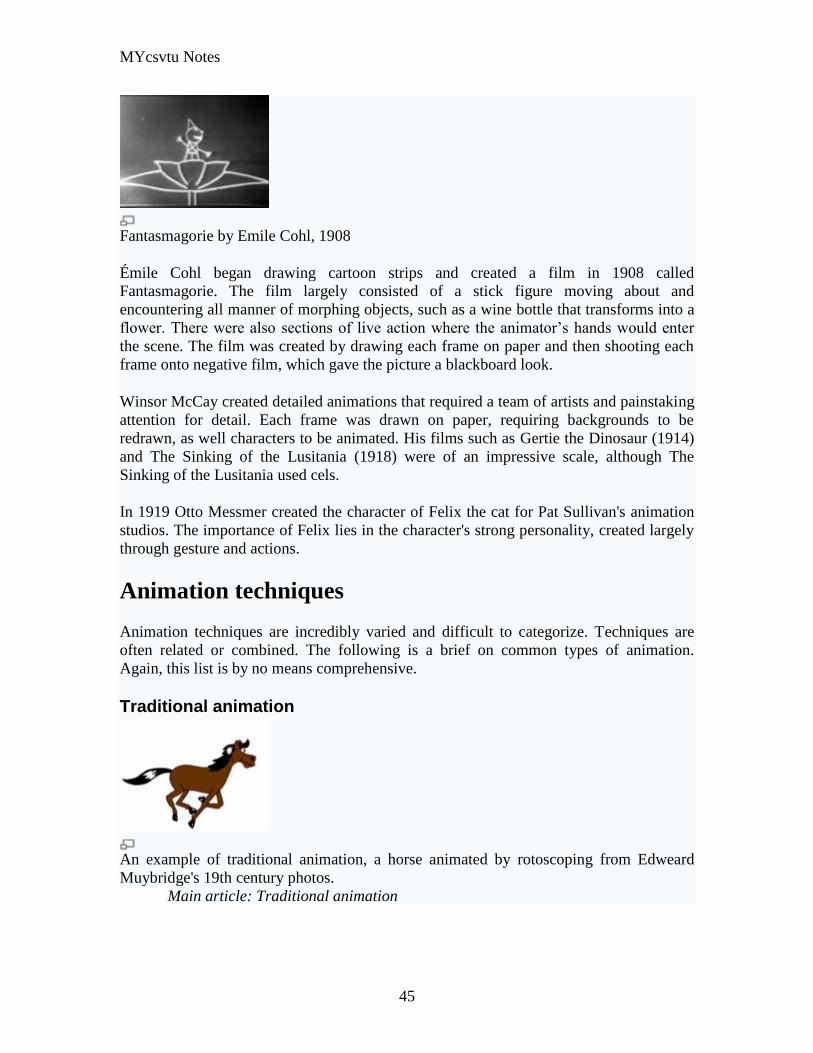
MYcsvtu Notes
45
Fantasmagorie by Emile Cohl 1908
Eacutemile Cohl began drawing cartoon strips and created a film in 1908 called
Fantasmagorie The film largely consisted of a stick figure moving about and
encountering all manner of morphing objects such as a wine bottle that transforms into a
flower There were also sections of live action where the animatorlsquos hands would enter
the scene The film was created by drawing each frame on paper and then shooting each
frame onto negative film which gave the picture a blackboard look
Winsor McCay created detailed animations that required a team of artists and painstaking
attention for detail Each frame was drawn on paper requiring backgrounds to be
redrawn as well characters to be animated His films such as Gertie the Dinosaur (1914)
and The Sinking of the Lusitania (1918) were of an impressive scale although The
Sinking of the Lusitania used cels
In 1919 Otto Messmer created the character of Felix the cat for Pat Sullivans animation
studios The importance of Felix lies in the characters strong personality created largely
through gesture and actions
Animation techniques
Animation techniques are incredibly varied and difficult to categorize Techniques are
often related or combined The following is a brief on common types of animation
Again this list is by no means comprehensive
Traditional animation
An example of traditional animation a horse animated by rotoscoping from Edweard
Muybridges 19th century photos
Main article Traditional animation
MYcsvtu Notes
46
Also called cel animation the frames of a traditionally animated movie are hand-drawn
The drawings are traced or copied onto transparent acetate sheets called cels which are
then placed over a painted background and photographed one by one on a rostrum
camera Nowadays the use of cels (and cameras) is mostly obsolete since the drawings
are scanned into computers and digitally transferred directly to 35 mm film The look
of traditional cel animation is still preserved and the character animators work has
remained essentially the same over the past 70 years Because of the digital influence
over modern cel animation it is also known as tradigital animation
Examples The Lion King Spirited Away Les Triplettes de Belleville
Full animation The most common style in animation known for its realistic and often very detailed art
Examples All Disney feature length animated films The Secret of NIMH The Iron Giant
Limited animation A cheaper process of making animated cartoons that does not follow a realistic
approach
Examples The Flintstones Yellow Submarine
Rubber hose The characters are usually cartoony and the animators have a lot of artistic freedom as
rubber hose animations dont have to follow the laws of physics and anatomy in the same
degree as the other main styles in animation
Examples Early Mickey Mouse cartoons Ren and Stimpy Popeye
Rotoscoping A technique where animators trace live action movement frame by frame for use in
animated films
Examples Gullivers Travels American Pop
Stop motion
Stop-motion animation is any type of animation which requires the animator to physically
alter the scene shoot a frame again alter the scene and shoot a frame and so on to create
the animation There are many different types of stop-motion animation some noteable
examples are listed below
Clay animation
MYcsvtu Notes
47
A clay animation scene from a TV commercial
Often abbreviated to claymation this is a type of stop-motion animation using
figures made of clay or a similar malleable material The figures may have an
armature or wire frame inside of them similar to puppet animation (below)
Alternatively the figures may be made entirely of clay such as in the films of
Bruce Bickford where clay creatures morph into a variety of different shapes
Examples Wallace and Gromit Dimensions of Dialogue by Jan Švankmajer The
Amazing Mr Bickford The Trap Door
Cutout animation In this type of stop-motion animation the animation is formed by moving 2-
dimensional pieces of material such as paper or cloth
Examples the animated sequences of Monty Pythons Flying Circus (often
referred to as Dada animation named after the Dada art movement[citation needed]
)
Tale of Tales early episodes of South Park
Silhouette animation A type of cutout animation where the viewer only sees black silhouettes
Example The Adventures of Prince Achmed the worlds oldest surviving
animated feature film from 1926
Graphic animation
Model animation In this form of animation model animated characters interact with and are a part
of the live-action world
Examples The films of Ray Harryhausen (Jason and the Argonauts) and Willis
OBrien (King Kong)
Go motion
Object animation
Pixilation Examples Neighbours
Puppet animation Puppet animation typically involves puppet figures interacting with each other in
a constructed environment in contrast to the real-world interaction in model
MYcsvtu Notes
48
animation (above) The puppets generally have an armature inside of them to
keep them still and steady as well as constraining them to move at particular
joints
Examples The Nightmare Before Christmas Robot Chicken The Tale of the Fox
Brickfilm
Puppetoon
Computer animation
A short gif animation
Like stop motion computer animation encompasses a variety of techniques the unifying
idea being that the animation is created digitally on a computer
2D animation Figures are created andor edited on the computer using 2D bitmap graphics or
created and edited using 2D vector graphics This includes automated
computerized versions of traditional animation techniques such as of tweening
morphing onion skinning and interpolated rotoscoping
Examples A Scanner Darkly Jib Jab
Analog computer animation
Flash animation
PowerPoint animation
A completely synthetic computer-generated scene
3D animation
MYcsvtu Notes
49
Figures are created in the computer using polygons To allow these meshes to
move they are given a digital armature (sculpture) This process is called rigging
Various other techniques can be applied such as mathematical functions
(gravity) simulated fur or hair effects such as fire and water and the use of
motion capture to name but a few
Examples The Incredibles Shrek
Cel-shaded animation
Morph target animation
Skeletal animation
Motion capture
Crowd simulation
Less common techniques
Drawn on film animation A technique where footage is produced by creating the
images directly on film stock
Paint-on-glass animationA technique for making animated films by manipulating slow-
drying oil paints on sheets of glass
Pinscreen animation Makes use of a screen filled with movable pins which can be
moved in or out by pressing an object onto the screen The screen is lit from the side so
that the pins cast shadows The technique has been used to create animated films with a
range of textural effects difficult to achieve with traditional cel animation
Sand animation Sand is moved around on a backlighted or frontlighted piece of glass to
create each frame for an animated film
Multimedia
Multimedia (Lat Multum + Medium) is media that uses multiple forms of information
content and information processing (eg text audio graphics animation video
interactivity) to inform or entertain the (user) audience Multimedia also refers to the use
of (but not limited to) electronic media to store and experience multimedia content
Multimedia is similar to traditional mixed media in fine art but with a broader scope The
term rich media is synonymous for interactive multimedia
Categorization
Multimedia may be broadly divided into linear and non-linear categories Linear active
content progresses without any navigation control for the viewer such as a cinema
presentation Non-linear content offers user interactivity to control progress as used with
MYcsvtu Notes
50
a computer game or used in self-paced computer based training Non-linear content is
also known as hypermedia content
Multimedia presentations can be live or recorded A recorded presentation may allow
interactivity via a navigation system A live multimedia presentation may allow
interactivity via interaction with the presenter or performer
There are 2 basic way to represent some information
Unimedium Presentation
Multimedia Presentation
In case of computer system the commonly used medioa for the purpose of storage
access and transmission of information are
bull Text
bull Graphics
bull Animation
bull Audio
bull Video
Multimedia Computer System require
bull Faster CPU
bull Larger Storage Devices
bull Larger Main Memory
bull Good Graphics Terminal
bull IO devices required to play an audio associated with the program
Transmission Mode
bull Asynchronous
bull Synchronous
bull Isochronous
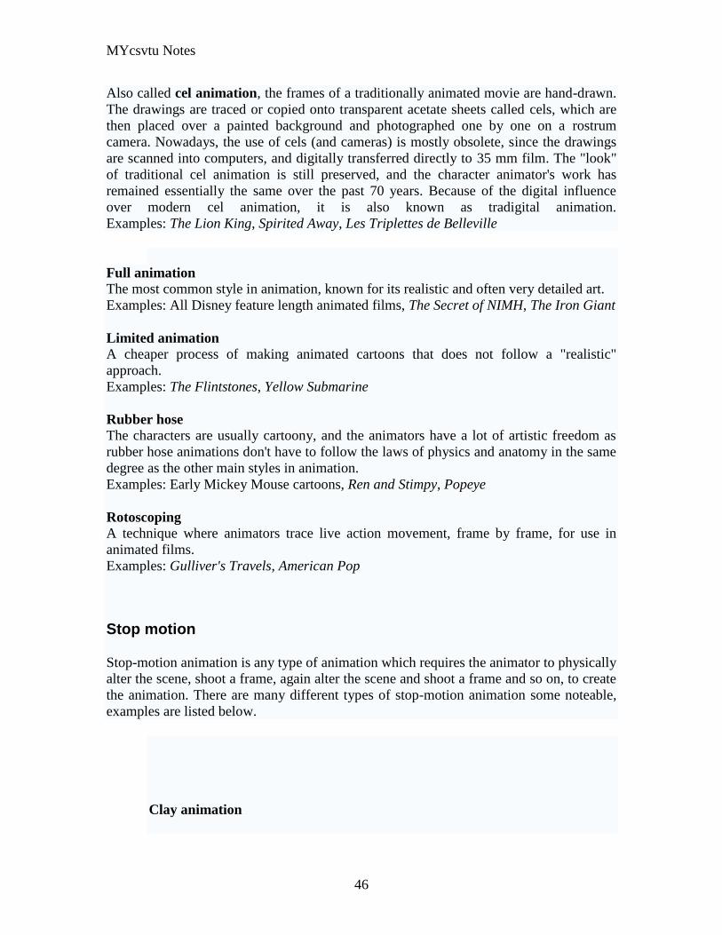
MYcsvtu Notes
46
Also called cel animation the frames of a traditionally animated movie are hand-drawn
The drawings are traced or copied onto transparent acetate sheets called cels which are
then placed over a painted background and photographed one by one on a rostrum
camera Nowadays the use of cels (and cameras) is mostly obsolete since the drawings
are scanned into computers and digitally transferred directly to 35 mm film The look
of traditional cel animation is still preserved and the character animators work has
remained essentially the same over the past 70 years Because of the digital influence
over modern cel animation it is also known as tradigital animation
Examples The Lion King Spirited Away Les Triplettes de Belleville
Full animation The most common style in animation known for its realistic and often very detailed art
Examples All Disney feature length animated films The Secret of NIMH The Iron Giant
Limited animation A cheaper process of making animated cartoons that does not follow a realistic
approach
Examples The Flintstones Yellow Submarine
Rubber hose The characters are usually cartoony and the animators have a lot of artistic freedom as
rubber hose animations dont have to follow the laws of physics and anatomy in the same
degree as the other main styles in animation
Examples Early Mickey Mouse cartoons Ren and Stimpy Popeye
Rotoscoping A technique where animators trace live action movement frame by frame for use in
animated films
Examples Gullivers Travels American Pop
Stop motion
Stop-motion animation is any type of animation which requires the animator to physically
alter the scene shoot a frame again alter the scene and shoot a frame and so on to create
the animation There are many different types of stop-motion animation some noteable
examples are listed below
Clay animation
MYcsvtu Notes
47
A clay animation scene from a TV commercial
Often abbreviated to claymation this is a type of stop-motion animation using
figures made of clay or a similar malleable material The figures may have an
armature or wire frame inside of them similar to puppet animation (below)
Alternatively the figures may be made entirely of clay such as in the films of
Bruce Bickford where clay creatures morph into a variety of different shapes
Examples Wallace and Gromit Dimensions of Dialogue by Jan Švankmajer The
Amazing Mr Bickford The Trap Door
Cutout animation In this type of stop-motion animation the animation is formed by moving 2-
dimensional pieces of material such as paper or cloth
Examples the animated sequences of Monty Pythons Flying Circus (often
referred to as Dada animation named after the Dada art movement[citation needed]
)
Tale of Tales early episodes of South Park
Silhouette animation A type of cutout animation where the viewer only sees black silhouettes
Example The Adventures of Prince Achmed the worlds oldest surviving
animated feature film from 1926
Graphic animation
Model animation In this form of animation model animated characters interact with and are a part
of the live-action world
Examples The films of Ray Harryhausen (Jason and the Argonauts) and Willis
OBrien (King Kong)
Go motion
Object animation
Pixilation Examples Neighbours
Puppet animation Puppet animation typically involves puppet figures interacting with each other in
a constructed environment in contrast to the real-world interaction in model
MYcsvtu Notes
48
animation (above) The puppets generally have an armature inside of them to
keep them still and steady as well as constraining them to move at particular
joints
Examples The Nightmare Before Christmas Robot Chicken The Tale of the Fox
Brickfilm
Puppetoon
Computer animation
A short gif animation
Like stop motion computer animation encompasses a variety of techniques the unifying
idea being that the animation is created digitally on a computer
2D animation Figures are created andor edited on the computer using 2D bitmap graphics or
created and edited using 2D vector graphics This includes automated
computerized versions of traditional animation techniques such as of tweening
morphing onion skinning and interpolated rotoscoping
Examples A Scanner Darkly Jib Jab
Analog computer animation
Flash animation
PowerPoint animation
A completely synthetic computer-generated scene
3D animation
MYcsvtu Notes
49
Figures are created in the computer using polygons To allow these meshes to
move they are given a digital armature (sculpture) This process is called rigging
Various other techniques can be applied such as mathematical functions
(gravity) simulated fur or hair effects such as fire and water and the use of
motion capture to name but a few
Examples The Incredibles Shrek
Cel-shaded animation
Morph target animation
Skeletal animation
Motion capture
Crowd simulation
Less common techniques
Drawn on film animation A technique where footage is produced by creating the
images directly on film stock
Paint-on-glass animationA technique for making animated films by manipulating slow-
drying oil paints on sheets of glass
Pinscreen animation Makes use of a screen filled with movable pins which can be
moved in or out by pressing an object onto the screen The screen is lit from the side so
that the pins cast shadows The technique has been used to create animated films with a
range of textural effects difficult to achieve with traditional cel animation
Sand animation Sand is moved around on a backlighted or frontlighted piece of glass to
create each frame for an animated film
Multimedia
Multimedia (Lat Multum + Medium) is media that uses multiple forms of information
content and information processing (eg text audio graphics animation video
interactivity) to inform or entertain the (user) audience Multimedia also refers to the use
of (but not limited to) electronic media to store and experience multimedia content
Multimedia is similar to traditional mixed media in fine art but with a broader scope The
term rich media is synonymous for interactive multimedia
Categorization
Multimedia may be broadly divided into linear and non-linear categories Linear active
content progresses without any navigation control for the viewer such as a cinema
presentation Non-linear content offers user interactivity to control progress as used with
MYcsvtu Notes
50
a computer game or used in self-paced computer based training Non-linear content is
also known as hypermedia content
Multimedia presentations can be live or recorded A recorded presentation may allow
interactivity via a navigation system A live multimedia presentation may allow
interactivity via interaction with the presenter or performer
There are 2 basic way to represent some information
Unimedium Presentation
Multimedia Presentation
In case of computer system the commonly used medioa for the purpose of storage
access and transmission of information are
bull Text
bull Graphics
bull Animation
bull Audio
bull Video
Multimedia Computer System require
bull Faster CPU
bull Larger Storage Devices
bull Larger Main Memory
bull Good Graphics Terminal
bull IO devices required to play an audio associated with the program
Transmission Mode
bull Asynchronous
bull Synchronous
bull Isochronous
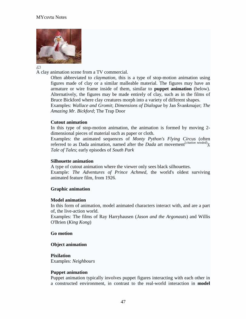
MYcsvtu Notes
47
A clay animation scene from a TV commercial
Often abbreviated to claymation this is a type of stop-motion animation using
figures made of clay or a similar malleable material The figures may have an
armature or wire frame inside of them similar to puppet animation (below)
Alternatively the figures may be made entirely of clay such as in the films of
Bruce Bickford where clay creatures morph into a variety of different shapes
Examples Wallace and Gromit Dimensions of Dialogue by Jan Švankmajer The
Amazing Mr Bickford The Trap Door
Cutout animation In this type of stop-motion animation the animation is formed by moving 2-
dimensional pieces of material such as paper or cloth
Examples the animated sequences of Monty Pythons Flying Circus (often
referred to as Dada animation named after the Dada art movement[citation needed]
)
Tale of Tales early episodes of South Park
Silhouette animation A type of cutout animation where the viewer only sees black silhouettes
Example The Adventures of Prince Achmed the worlds oldest surviving
animated feature film from 1926
Graphic animation
Model animation In this form of animation model animated characters interact with and are a part
of the live-action world
Examples The films of Ray Harryhausen (Jason and the Argonauts) and Willis
OBrien (King Kong)
Go motion
Object animation
Pixilation Examples Neighbours
Puppet animation Puppet animation typically involves puppet figures interacting with each other in
a constructed environment in contrast to the real-world interaction in model
MYcsvtu Notes
48
animation (above) The puppets generally have an armature inside of them to
keep them still and steady as well as constraining them to move at particular
joints
Examples The Nightmare Before Christmas Robot Chicken The Tale of the Fox
Brickfilm
Puppetoon
Computer animation
A short gif animation
Like stop motion computer animation encompasses a variety of techniques the unifying
idea being that the animation is created digitally on a computer
2D animation Figures are created andor edited on the computer using 2D bitmap graphics or
created and edited using 2D vector graphics This includes automated
computerized versions of traditional animation techniques such as of tweening
morphing onion skinning and interpolated rotoscoping
Examples A Scanner Darkly Jib Jab
Analog computer animation
Flash animation
PowerPoint animation
A completely synthetic computer-generated scene
3D animation
MYcsvtu Notes
49
Figures are created in the computer using polygons To allow these meshes to
move they are given a digital armature (sculpture) This process is called rigging
Various other techniques can be applied such as mathematical functions
(gravity) simulated fur or hair effects such as fire and water and the use of
motion capture to name but a few
Examples The Incredibles Shrek
Cel-shaded animation
Morph target animation
Skeletal animation
Motion capture
Crowd simulation
Less common techniques
Drawn on film animation A technique where footage is produced by creating the
images directly on film stock
Paint-on-glass animationA technique for making animated films by manipulating slow-
drying oil paints on sheets of glass
Pinscreen animation Makes use of a screen filled with movable pins which can be
moved in or out by pressing an object onto the screen The screen is lit from the side so
that the pins cast shadows The technique has been used to create animated films with a
range of textural effects difficult to achieve with traditional cel animation
Sand animation Sand is moved around on a backlighted or frontlighted piece of glass to
create each frame for an animated film
Multimedia
Multimedia (Lat Multum + Medium) is media that uses multiple forms of information
content and information processing (eg text audio graphics animation video
interactivity) to inform or entertain the (user) audience Multimedia also refers to the use
of (but not limited to) electronic media to store and experience multimedia content
Multimedia is similar to traditional mixed media in fine art but with a broader scope The
term rich media is synonymous for interactive multimedia
Categorization
Multimedia may be broadly divided into linear and non-linear categories Linear active
content progresses without any navigation control for the viewer such as a cinema
presentation Non-linear content offers user interactivity to control progress as used with
MYcsvtu Notes
50
a computer game or used in self-paced computer based training Non-linear content is
also known as hypermedia content
Multimedia presentations can be live or recorded A recorded presentation may allow
interactivity via a navigation system A live multimedia presentation may allow
interactivity via interaction with the presenter or performer
There are 2 basic way to represent some information
Unimedium Presentation
Multimedia Presentation
In case of computer system the commonly used medioa for the purpose of storage
access and transmission of information are
bull Text
bull Graphics
bull Animation
bull Audio
bull Video
Multimedia Computer System require
bull Faster CPU
bull Larger Storage Devices
bull Larger Main Memory
bull Good Graphics Terminal
bull IO devices required to play an audio associated with the program
Transmission Mode
bull Asynchronous
bull Synchronous
bull Isochronous
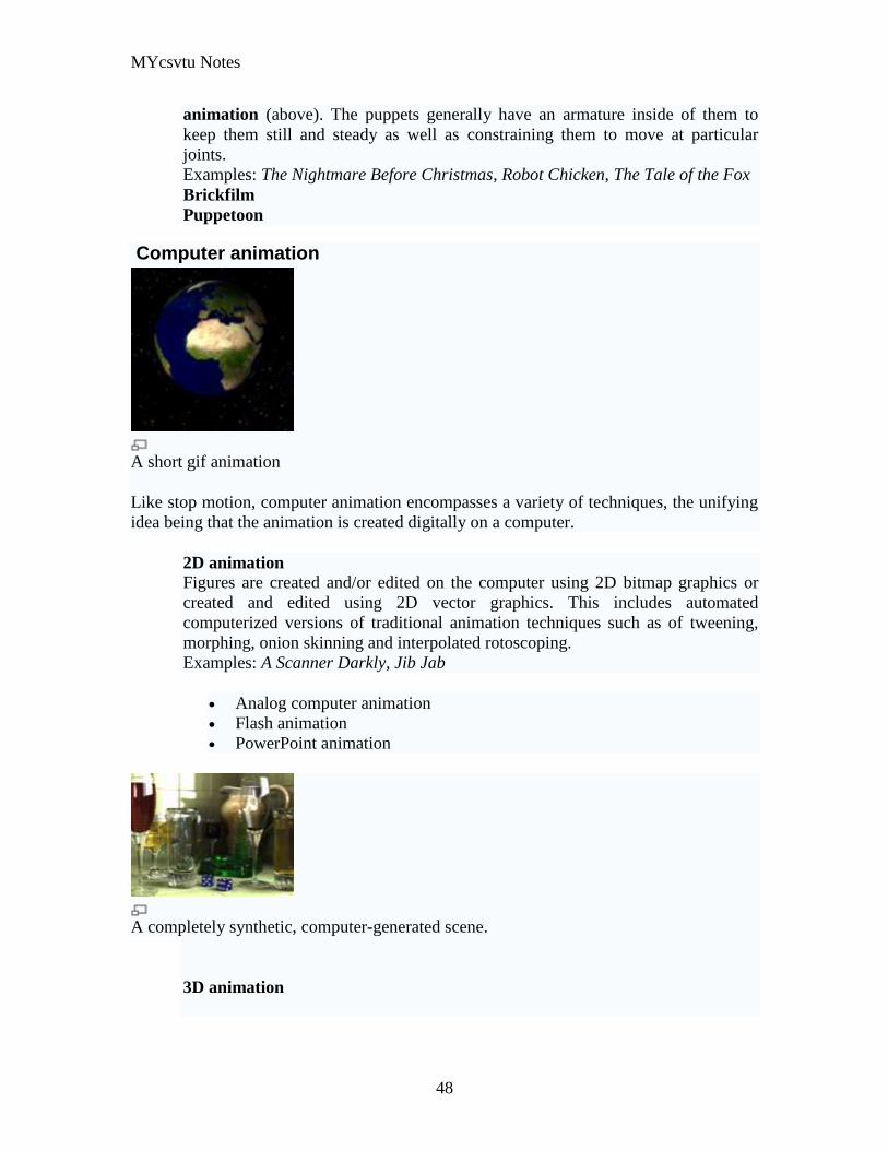
MYcsvtu Notes
48
animation (above) The puppets generally have an armature inside of them to
keep them still and steady as well as constraining them to move at particular
joints
Examples The Nightmare Before Christmas Robot Chicken The Tale of the Fox
Brickfilm
Puppetoon
Computer animation
A short gif animation
Like stop motion computer animation encompasses a variety of techniques the unifying
idea being that the animation is created digitally on a computer
2D animation Figures are created andor edited on the computer using 2D bitmap graphics or
created and edited using 2D vector graphics This includes automated
computerized versions of traditional animation techniques such as of tweening
morphing onion skinning and interpolated rotoscoping
Examples A Scanner Darkly Jib Jab
Analog computer animation
Flash animation
PowerPoint animation
A completely synthetic computer-generated scene
3D animation
MYcsvtu Notes
49
Figures are created in the computer using polygons To allow these meshes to
move they are given a digital armature (sculpture) This process is called rigging
Various other techniques can be applied such as mathematical functions
(gravity) simulated fur or hair effects such as fire and water and the use of
motion capture to name but a few
Examples The Incredibles Shrek
Cel-shaded animation
Morph target animation
Skeletal animation
Motion capture
Crowd simulation
Less common techniques
Drawn on film animation A technique where footage is produced by creating the
images directly on film stock
Paint-on-glass animationA technique for making animated films by manipulating slow-
drying oil paints on sheets of glass
Pinscreen animation Makes use of a screen filled with movable pins which can be
moved in or out by pressing an object onto the screen The screen is lit from the side so
that the pins cast shadows The technique has been used to create animated films with a
range of textural effects difficult to achieve with traditional cel animation
Sand animation Sand is moved around on a backlighted or frontlighted piece of glass to
create each frame for an animated film
Multimedia
Multimedia (Lat Multum + Medium) is media that uses multiple forms of information
content and information processing (eg text audio graphics animation video
interactivity) to inform or entertain the (user) audience Multimedia also refers to the use
of (but not limited to) electronic media to store and experience multimedia content
Multimedia is similar to traditional mixed media in fine art but with a broader scope The
term rich media is synonymous for interactive multimedia
Categorization
Multimedia may be broadly divided into linear and non-linear categories Linear active
content progresses without any navigation control for the viewer such as a cinema
presentation Non-linear content offers user interactivity to control progress as used with
MYcsvtu Notes
50
a computer game or used in self-paced computer based training Non-linear content is
also known as hypermedia content
Multimedia presentations can be live or recorded A recorded presentation may allow
interactivity via a navigation system A live multimedia presentation may allow
interactivity via interaction with the presenter or performer
There are 2 basic way to represent some information
Unimedium Presentation
Multimedia Presentation
In case of computer system the commonly used medioa for the purpose of storage
access and transmission of information are
bull Text
bull Graphics
bull Animation
bull Audio
bull Video
Multimedia Computer System require
bull Faster CPU
bull Larger Storage Devices
bull Larger Main Memory
bull Good Graphics Terminal
bull IO devices required to play an audio associated with the program
Transmission Mode
bull Asynchronous
bull Synchronous
bull Isochronous
MYcsvtu Notes
50
a computer game or used in self-paced computer based training Non-linear content is
also known as hypermedia content
Multimedia presentations can be live or recorded A recorded presentation may allow
interactivity via a navigation system A live multimedia presentation may allow
interactivity via interaction with the presenter or performer
There are 2 basic way to represent some information
Unimedium Presentation
Multimedia Presentation
In case of computer system the commonly used medioa for the purpose of storage
access and transmission of information are
bull Text
bull Graphics
bull Animation
bull Audio
bull Video
Multimedia Computer System require
bull Faster CPU
bull Larger Storage Devices
bull Larger Main Memory
bull Good Graphics Terminal
bull IO devices required to play an audio associated with the program
Transmission Mode
bull Asynchronous
bull Synchronous
bull Isochronous