classification of simulators logic simulators emulator-basedschematic-basedhdl-based...
TRANSCRIPT
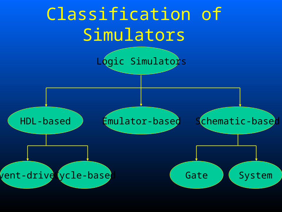
Classification of Simulators
Logic Simulators
Emulator-based Schematic-basedHDL-based
Event-driven Cycle-based Gate System
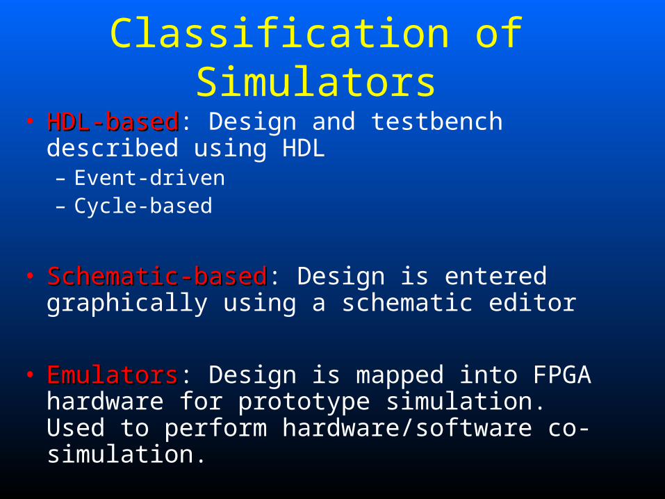
Classification of Simulators
• HDL-basedHDL-based: Design and testbench described using HDL– Event-driven– Cycle-based
• Schematic-basedSchematic-based: Design is entered graphically using a schematic editor
• EmulatorsEmulators: Design is mapped into FPGA hardware for prototype simulation. Used to perform hardware/software co-simulation.
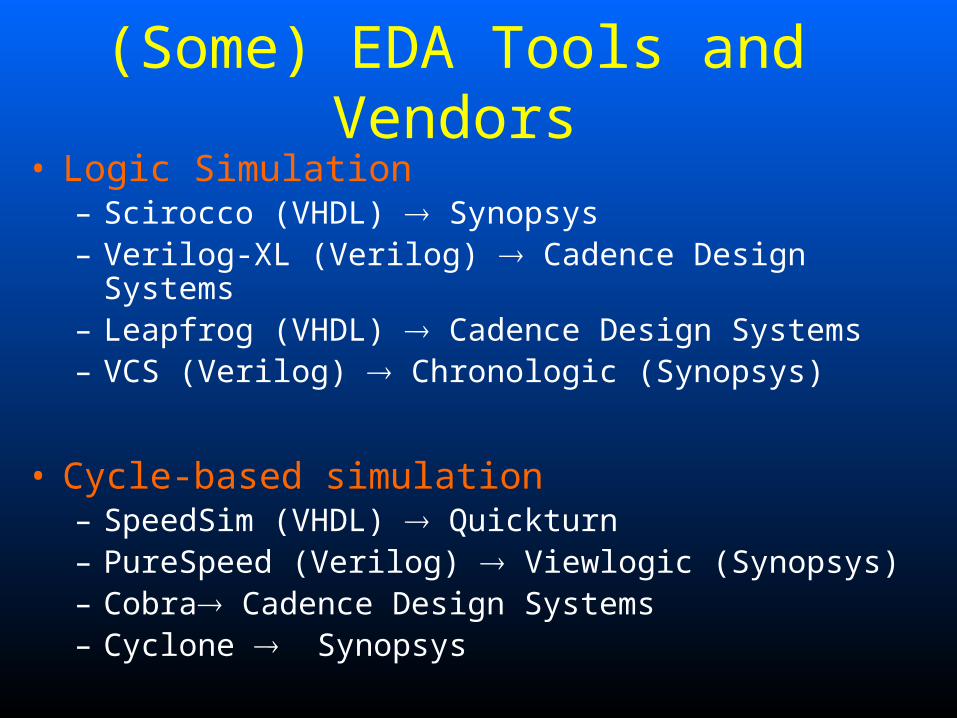
(Some) EDA Tools and Vendors• Logic Simulation
– Scirocco (VHDL) Synopsys– Verilog-XL (Verilog) Cadence Design Systems– Leapfrog (VHDL) Cadence Design Systems– VCS (Verilog) Chronologic (Synopsys)
• Cycle-based simulation– SpeedSim (VHDL) Quickturn– PureSpeed (Verilog) Viewlogic (Synopsys)– Cobra Cadence Design Systems– Cyclone Synopsys
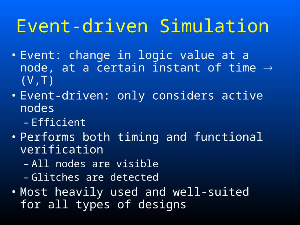
Event-driven Simulation
• Event: change in logic value at a node, at a certain instant of time (V,T)
• Event-driven: only considers active nodes– Efficient
• Performs both timing and functional verification– All nodes are visible– Glitches are detected
• Most heavily used and well-suited for all types of designs
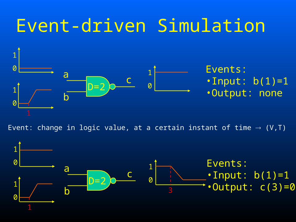
Event-driven Simulation
Event: change in logic value, at a certain instant of time (V,T)
10
1
0
1
0
1
D=2a
b
cEvents:•Input: b(1)=1•Output: none
10
1
0
1
0
1
D=2a
b
cEvents:•Input: b(1)=1•Output: c(3)=03
Event-driven Simulation
• Uses a timewheel to manage the relationship between components
• TimewheelTimewheel = list of all events not processed yet, sorted in time (complete ordering)
• When event is generated, it is put in the appropriate point in the timewheel to ensure causality
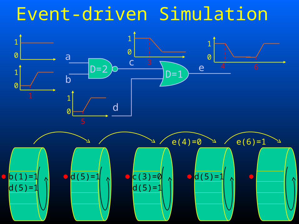
Event-driven Simulation
b(1)=1d(5)=1
D=1
10
1
0
1
D=2a
b
c
d(5)=1
d5
0
1
e
0
1
3
c(3)=0d(5)=1
0
1
4
d(5)=1
e(4)=0
6
e(6)=1
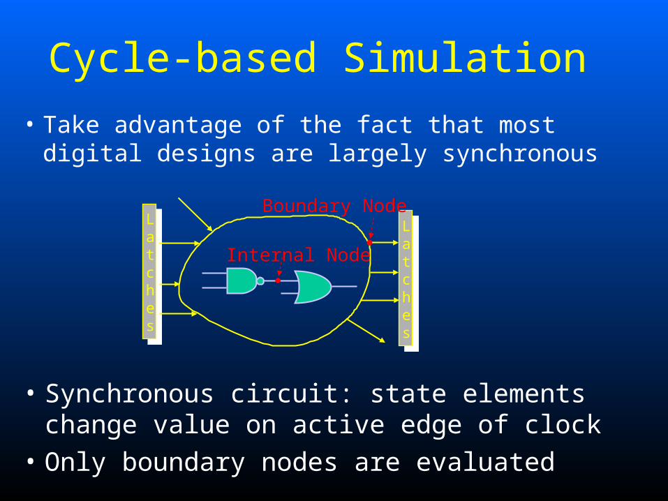
Cycle-based Simulation
• Take advantage of the fact that most digital designs are largely synchronous
• Synchronous circuit: state elements change value on active edge of clock
• Only boundary nodes are evaluated
Internal Node
Boundary NodeLatches
Latches
Cycle-based Simulation
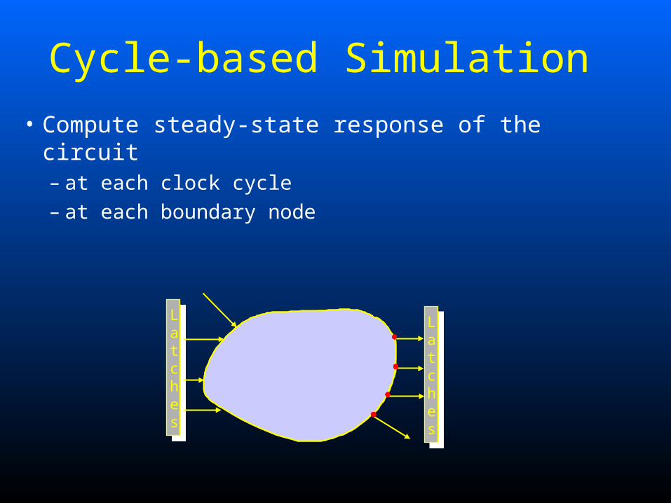
• Compute steady-state response of the circuit – at each clock cycle– at each boundary node
Latches
Latches
Internal Node
Cycle-based versus Event-driven
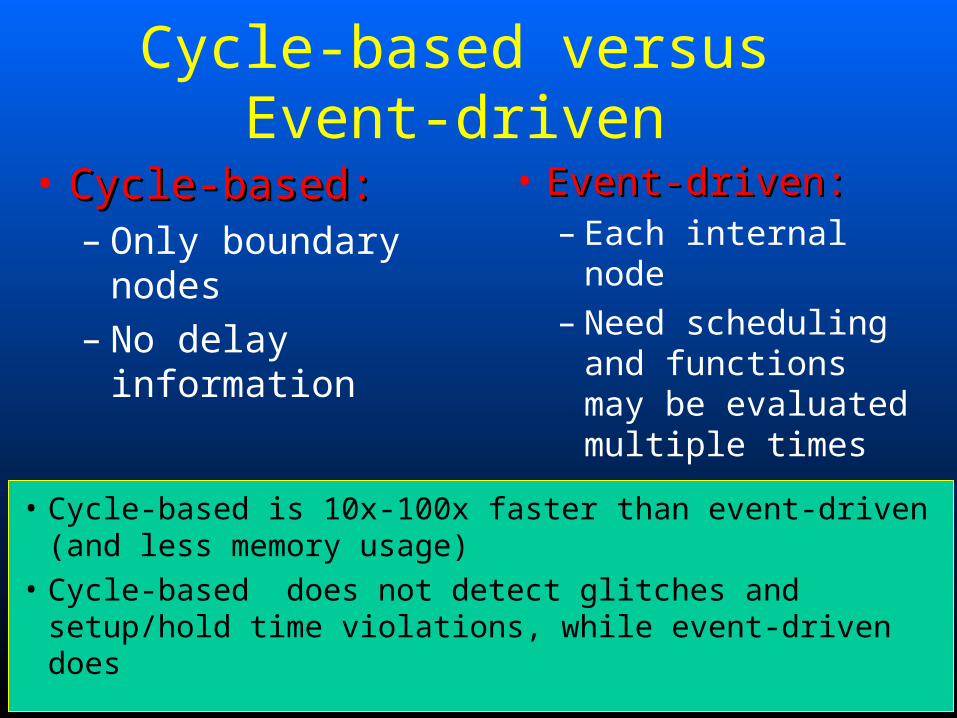
• Cycle-based:Cycle-based:– Only boundary nodes– No delay information
• Event-driven:Event-driven:– Each internal node– Need scheduling and
functions may be evaluated multiple times
• Cycle-based is 10x-100x faster than event-driven (and less memory usage)
• Cycle-based does not detect glitches and setup/hold time violations, while event-driven does
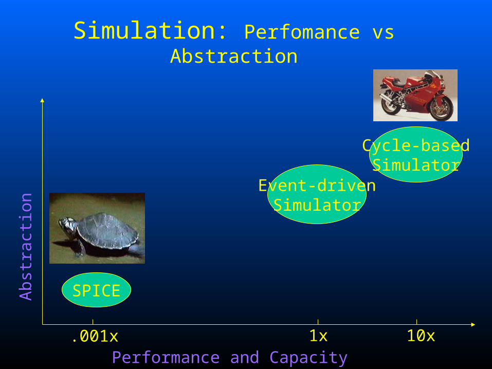
Simulation: Perfomance vs Abstraction
.001x
SPICE
Event-drivenSimulator
Cycle-basedSimulator
1x 10xPerformance and Capacity
Abs
trac
tion
Simulation Testplan
• Simulation– Write test vectors– Run simulation– Inspect results
• About test vectors– HDL code coverage
Digitaalsüsteemide verifitseerimise kursus 13
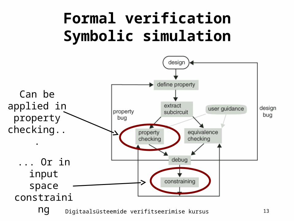
Formal verificationSymbolic simulation
Can be applied in property checking...
... Or in input space
constraining
Digitaalsüsteemide verifitseerimise kursus 14
Symbolic simulation
• Free variables (primary inputs, flip-flops) and internal variables.
• Considers relations between free variables, not the stimuli values. Good for verifying properties.
• Circuit unrolling for sequential circuits. Expressions will become complex!
• BDDS used in representing the expressions.

Digitaalsüsteemide verifitseerimise kursus 15
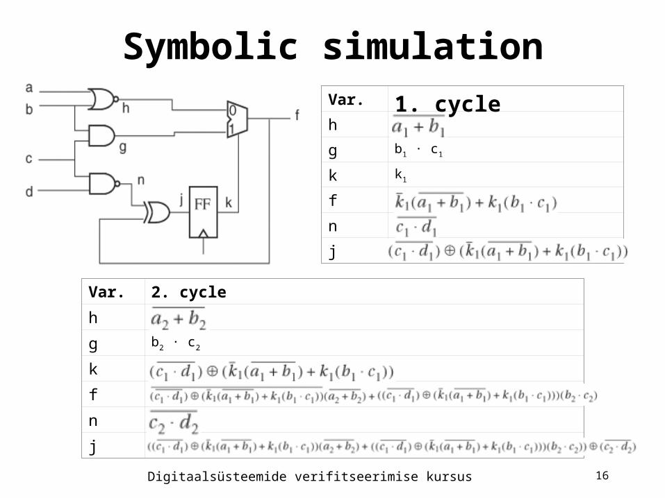
Circuit unrolling:
Symbolic simulation
Digitaalsüsteemide verifitseerimise kursus 16
Var. 1. cycleh
g b1 · c1
k k1
f
n
j
Var. 2. cycle
h
g b2 · c2
k
f
n
j
Symbolic simulation
Digitaalsüsteemide verifitseerimise kursus 17
Symbolic verification
• Symbolic simulation allows considering several stimuli simultaneously.
• Thus suitable for verifying properties (assertions)
• Properties may be time-limited (bound) or time-unlimited (unbound)
• Symbolic verification can be applied to the former
Digitaalsüsteemide verifitseerimise kursus 18
Sisendruumi kitsendamine
• Mõnedele sisenditele omistatakse konkreetsed väärtused ja simuleeritakse
• Vähendab oluliselt avaldiste keerukust• Eesmärgiks võib olla osalise funktsionaalsuse
kontroll (funktsionaalne tükeldamine) või keskkonna kirjeldamine
• Piiril, kui kõik vabad muutujad omavad väärtust, on tegu traditsioonilise simuleerimisega
Digitaalsüsteemide verifitseerimise kursus 19
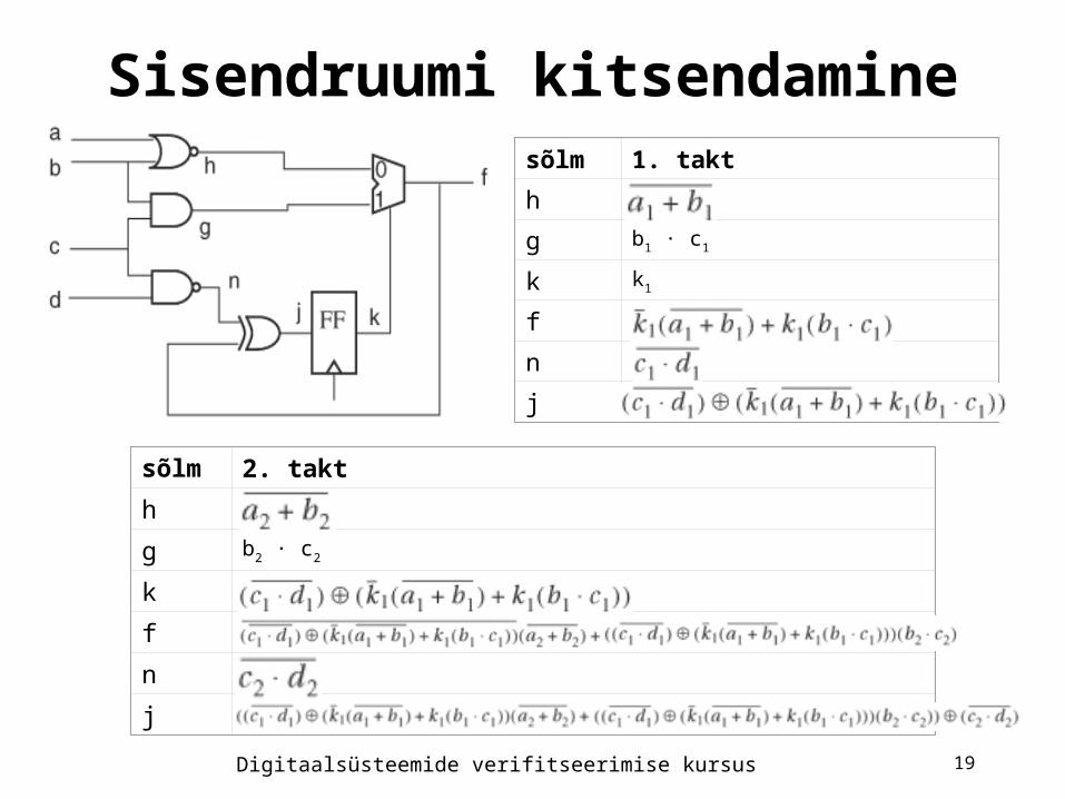
Sisendruumi kitsendaminesõlm 1. takt
h
g b1 · c1
k k1
f
n
j
sõlm 2. takt
h
g b2 · c2
k
f
n
j
Digitaalsüsteemide verifitseerimise kursus 20
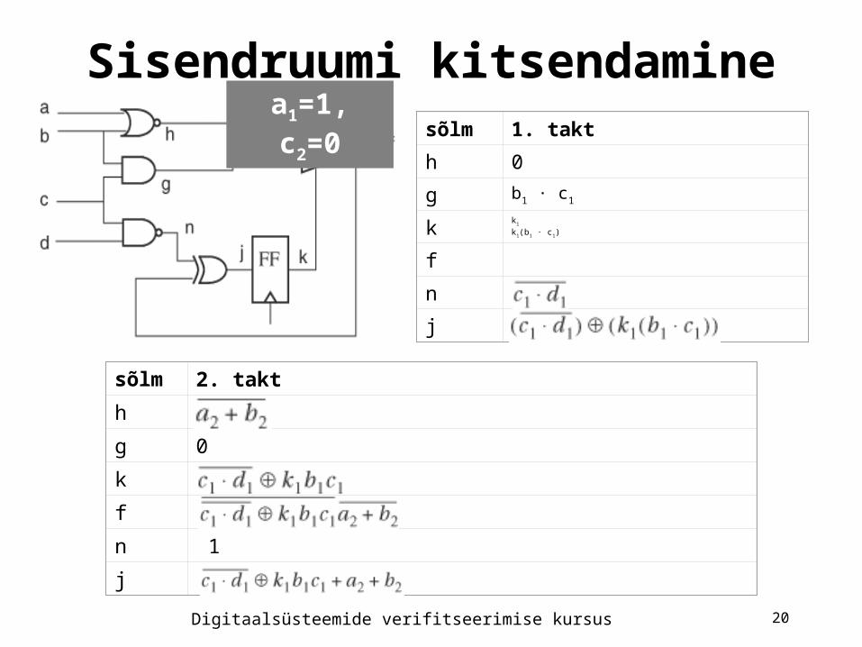
Sisendruumi kitsendaminesõlm 1. takt
h 0
g b1 · c1
kk1
k1(b1 · c1)
f
n
j
sõlm 2. takt
h
g 0
k
f
n 1
j
a1=1, c2=0
Digitaalsüsteemide verifitseerimise kursus 21
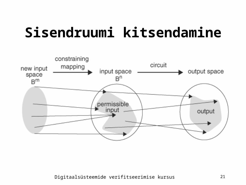
Sisendruumi kitsendamine
Digitaalsüsteemide verifitseerimise kursus 22
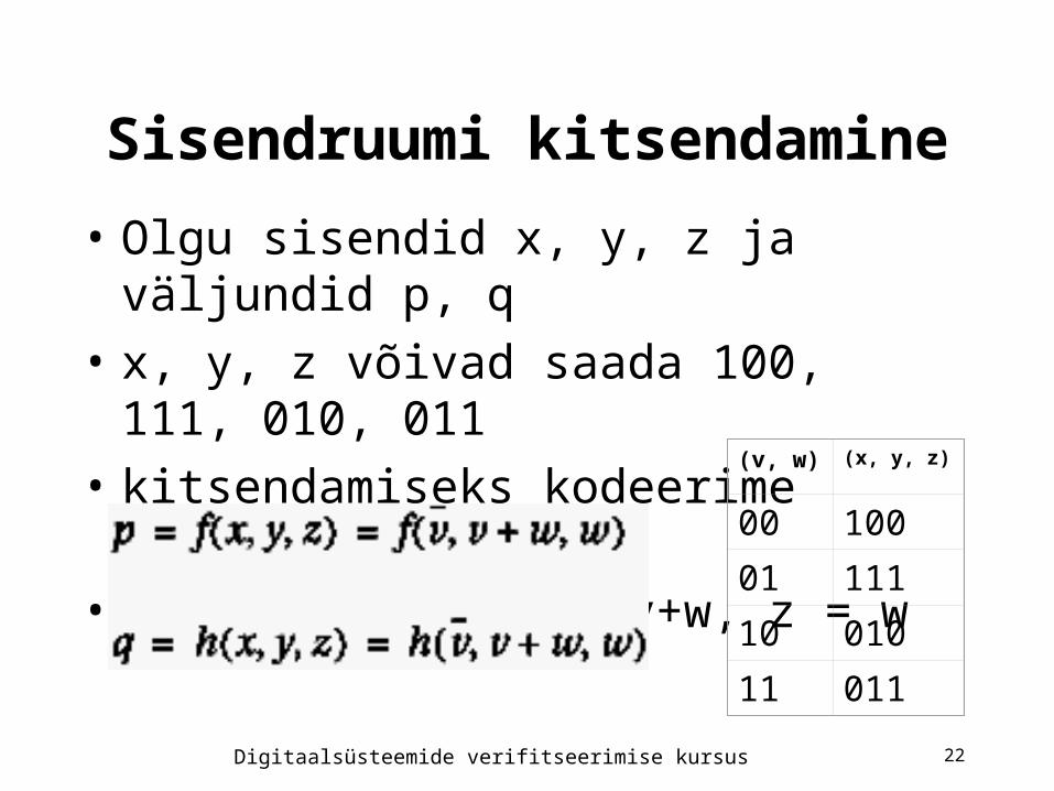
Sisendruumi kitsendamine
• Olgu sisendid x, y, z ja väljundid p, q
• x, y, z võivad saada 100, 111, 010, 011
• kitsendamiseks kodeerime muutujatega v, w
• saame x = ¬v, y = v+w, z = w(v, w) (x, y, z)
00 100
01 111
10 010
11 011