clean development mechanism project design document form...
TRANSCRIPT
PROJECT DESIGN DOCUMENT FORM (CDM-SSC-PDD) - Version 03 CDM – Executive Board
1
CLEAN DEVELOPMENT MECHANISM PROJECT DESIGN DOCUMENT FORM (CDM-SSC-PDD)
Version 03 - in effect as of: 22 December 2006
CONTENTS A. General description of the small scale project activity B. Application of a baseline and monitoring methodology C. Duration of the project activity / crediting period D. Environmental impacts E. Stakeholders’ comments
Annexes Annex 1: Contact information on participants in the proposed small scale project activity Annex 2: Information regarding public funding Annex 3: Baseline information
Annex 4: Monitoring Information

PROJECT DESIGN DOCUMENT FORM (CDM-SSC-PDD) - Version 03 CDM – Executive Board
2
Revision history of this document Version Number
Date Description and reason of revision
01 21 January 2003
Initial adoption
02 8 July 2005 • The Board agreed to revise the CDM SSC PDD to reflect guidance and clarifications provided by the Board since version 01 of this document.
• As a consequence, the guidelines for completing CDM SSC PDD have been revised accordingly to version 2. The latest version can be found at <http://cdm.unfccc.int/Reference/Documents>.
03 22 December 2006
• The Board agreed to revise the CDM project design document for small-scale activities (CDM-SSC-PDD), taking into account CDM-PDD and CDM-NM.
PROJECT DESIGN DOCUMENT FORM (CDM-SSC-PDD) - Version 03 CDM – Executive Board
3
SECTION A. General description of small-scale project activity A.1 Title of the small-scale project activity: Comprehensive treatment of organic wastewater at Sawar Bukit Palm Oil Mill, Malaysia using decanter, aeration and flocculants A.2. Description of the small-scale project activity: The project will involve comprehensive treatment of Palm Oil Mill Effluent through use of a decanter, aeration and flocculant (‘the Project). The project will be located at the Sawar Bukit Palm Oil Mill, Johor State, in Peninsular Malaysia (‘the Mill’). The Mill has the capacity to handle 50 tonnes per hour of fresh fruit bunch (FFB). This FFB is processed into crude palm oil and a number of other useful by-products. During the processing of the FFB, a significant amount of waste water is produced, with high content of organic waste materials, known as Palm Oil Mill Effluent (POME). The ratio of POME produced is approximately 0.6 tonnes per tonne FFB processed, with a typical COD value of around 72,000 mg / litre. Thus the total amount of organic material contained in the Mill’s wastewater is around 10,000 tonnes per annum. This wastewater is currently treated in a system of anaerobic holding tanks and ponds, with final treatment provided by an aerobic pond. The treated wastewater is then released into a nearby river. In the project, it is proposed to treat the wastewater first in a decanter to remove the larger particles of organic material. The wastewater stream will then pass through the existing aerobic ponds, but with improvement of the blower system and a longer residence time to promote more complete breakdown of the remaining fine particles of organic material. The third phase of treatment will be to mix the wastewater with a flocculent material, which will encourage the remaining organic particles to clump together into a solid mass, which can then be easily removed from the wastewater stream. In the baseline, a significant proportion of the reduction in COD of the wastewater is achieved using anaerobic ponds, which results in significant release of methane to the atmosphere. However in the Project, this will be replaced by an approach which minimises any anaerobic activity. Further, the approach proposed by the Project, in particular the final stage of treatment with flocculent, will allow for a much fuller treatment of the wastewater. The waste water thus treated would be of sufficient quality for recycling within the Mill, and would of course fully meet the required environmental standards for release into nearby wasterways. Next, the sustainable development benefits of the Project are examined through 3 categories: economic, environmental and social. Sustainable Development Benefits - economic The organic material recovered from the decanter, and from the flocculation process, will have a high calorific value, and, after drying, will make a useful supplementary fuel for the Mill’s boilers. Although these boilers are already operated using organic waste materials from the FFB treatment process, nonetheless there is a market for some of the organic products of the Mill. Substitution with the material recovered by the Project will enable the Mill to sell more of its waste material to outside users. This

PROJECT DESIGN DOCUMENT FORM (CDM-SSC-PDD) - Version 03 CDM – Executive Board
4
represents not only an increase in the Mill’s income, but also an increase in the availability of sustainable biomass fuels for other users in the area. Further, the energy-consuming processes used in the Project will all be supplied by the Mill’s existing biomass co-generation system. Additional electricity consumed by the aeration system and the decanter, and steam-drying of the material recovered from the decanter and the flocculation process all fit into this category. Sustainable Development Benefits – environmental The flocculent-based final treatment of the POME proposed by the Project enables a significantly superior reduction in the final COD load of wastewater emerging from the Mill. It is targeted to bring COD loads down to 100 g/litre or less. The current anaerobic pond system leaves open bodies of water with thick crusts of organic material which produce a noxious smell, and take up valuable land space. Once the effectiveness of the Project has been demonstrated, it will become possible for the Mill to beautify this space or use it for a more productive means. Sustainable Development Benefits – social Awareness of the possibilities available for cleaning up the wastewater from POMs is not always strong. The Project will provide a strong example of the level of COD drop that can be achieved when the appropriate techniques are applied. In addition, the Project will enable Malaysian engineers to gain first hand experience of operation of a flocculent-based wastewater treatment system, which should enable the spread of the technology to other applications both within the palm oil sector and in other related wastewater treatment fields. A.3. Project participants: Name of Party involved (*) ((host) indicates a host Party)
Private and/or public entity(ies) project participants (*) (as applicable)
Kindly indicate if the Party involved wishes to be considered as project participant (Yes/No)
Malaysia KILANG KELAPA SAWIT BUKIT PASIR SDN.BHD. No
Japan Tokyo Electric Power Environmental Engineering Co., Inc (TEE) No
(*) In accordance with the CDM modalities and procedures, at the time of making the CDM-PDD public at the stage of validation, a Party involved may or may not have provided its approval. At the time of requesting registration, the approval by the Party(ies) involved is required.

PROJECT DESIGN DOCUMENT FORM (CDM-SSC-PDD) - Version 03 CDM – Executive Board
5
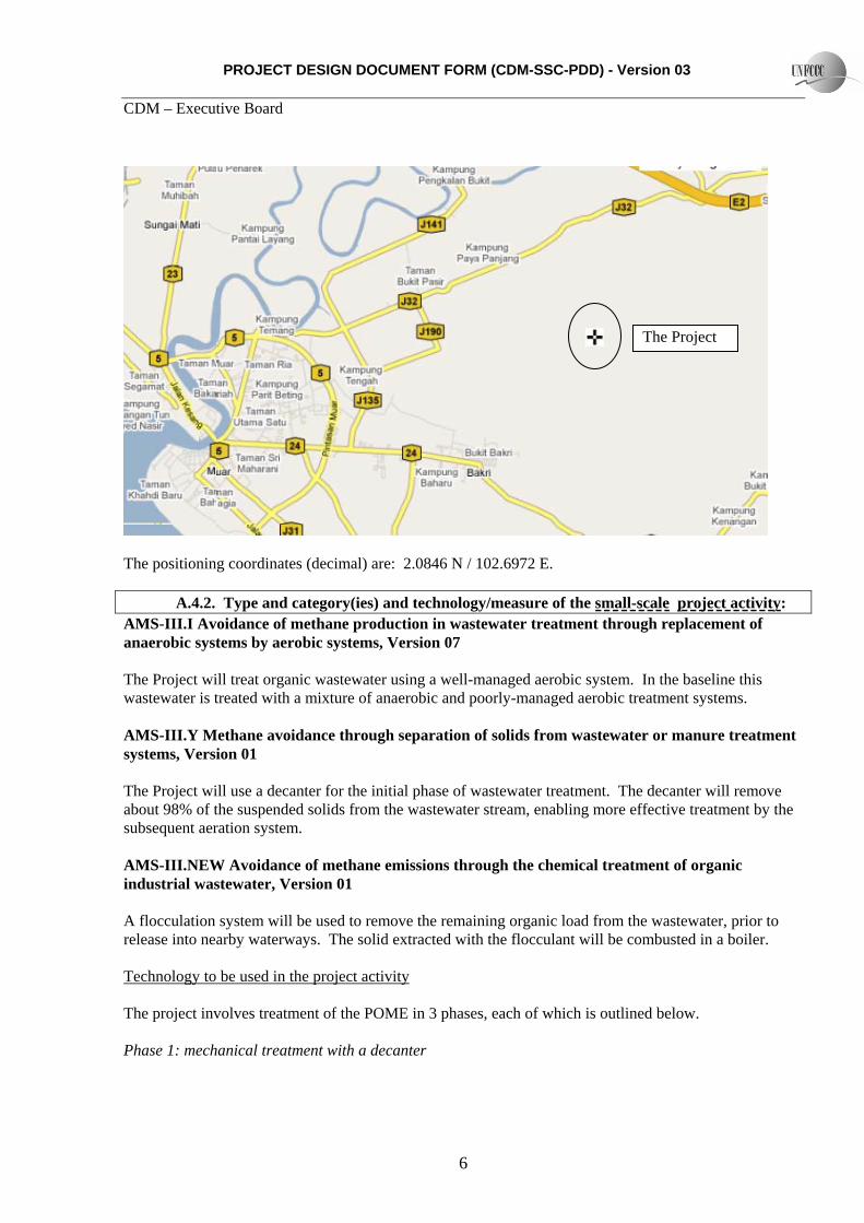
A.4. Technical description of the small-scale project activity: A.4.1. Location of the small-scale project activity: A.4.1.1. Host Party(ies): Malaysia A.4.1.2. Region/State/Province etc.: Johor A.4.1.3. City/Town/Community etc: Muar A.4.1.4. Details of physical location, including information allowing the unique identification of this small-scale project activity : Kilang Kelapa Bukit Pasir Sdn. Bhd., Batu 11, Jalan Bukit Pasir, 84300 Bukit Pasir, Muar, Johor, Southern Peninsular Malaysia.
PROJECT DESIGN DOCUMENT FORM (CDM-SSC-PDD) - Version 03 CDM – Executive Board
6
The Project
The positioning coordinates (decimal) are: 2.0846 N / 102.6972 E. A.4.2. Type and category(ies) and technology/measure of the small-scale project activity: AMS-III.I Avoidance of methane production in wastewater treatment through replacement of anaerobic systems by aerobic systems, Version 07 The Project will treat organic wastewater using a well-managed aerobic system. In the baseline this wastewater is treated with a mixture of anaerobic and poorly-managed aerobic treatment systems. AMS-III.Y Methane avoidance through separation of solids from wastewater or manure treatment systems, Version 01 The Project will use a decanter for the initial phase of wastewater treatment. The decanter will remove about 98% of the suspended solids from the wastewater stream, enabling more effective treatment by the subsequent aeration system. AMS-III.NEW Avoidance of methane emissions through the chemical treatment of organic industrial wastewater, Version 01 A flocculation system will be used to remove the remaining organic load from the wastewater, prior to release into nearby waterways. The solid extracted with the flocculant will be combusted in a boiler. Technology to be used in the project activity The project involves treatment of the POME in 3 phases, each of which is outlined below. Phase 1: mechanical treatment with a decanter

PROJECT DESIGN DOCUMENT FORM (CDM-SSC-PDD) - Version 03 CDM – Executive Board
7
A decanter makes use of the natural settling effect of gravity acting on the suspended solids in the wastewater. The decanter promotes this settling, to enable a rapid removal of suspended solid in a short throughflow time. The decanter system is shown in the following diagram:
The wastewater then proceeds to Phase II. The solid waste extracted from the decanter is dried using excess steam from the Mill’s boilers. The dried waste has a moderate calorific value, and can be used as a supplementary fuel in the Mill’s boilers. Phase 2 : aerobic treatment The aerobic pond can hold up to 7,300 m3 of wastewater. Aeration is provided by a 22kW / 41Amp pump, which can inject 18 – 20 m3 of air into the pond per minute. The aeration is in line with strict Japanese government standards for wastewater management, and can therefore be considered to be a “well-managed aerobic pond”. Phase 3 : flocculent treatment After emerging from the aerobic pond, the wastewater will be fed into a custom-designed system for mixing wastewater with flocculent, and removing the floc thus obtained. The flocculent used will be a combination of inorganic polymers, whose negative charge will attract the positively charged organic particles in the wastewater; and fly ash, which will provide key minerals for the ion exchange process, and add bulk to the flocculent. The flocculent is mixed with the wastewater in a inverted conical receptacle, where the floc is then separated from the body of the wastewater. The wastewater is then ready for release into nearby waterways, or for recycling as the process water for the Mill. The solid

PROJECT DESIGN DOCUMENT FORM (CDM-SSC-PDD) - Version 03 CDM – Executive Board
8
material thus separated is then removed and put through a drying process. The dried solid material has a high calorific value, and is used as a supplementary fuel in the Mill’s boilers. The flocculation process is outlined in the system diagram below:
A.4.3 Estimated amount of emission reductions over the chosen crediting period: The 7-year renewable crediting period option is selected for the Project. Annual estimates, together with total and average estimates for the first crediting period are shown in the table below:
Years Annual estimation of emission reductionsin tonnes CO2e
Year 1 35,562 Year 2 35,562 Year 3 35,562 Year 4 35,562 Year 5 35,562 Year 6 35,562 Year 7 35,562 Year 8 35,562 Year 9 35,562
Year 10 35,562

PROJECT DESIGN DOCUMENT FORM (CDM-SSC-PDD) - Version 03 CDM – Executive Board
9
Total estimated reductions (tonnes CO22) 355,620 Total number of crediting years 10
Annual average over the crediting period of estimated reductions (tonnes of CO2e) 35,562
Table A.4 I: Emission reductions in the first crediting period A.4.4. Public funding of the small-scale project activity: The project has received a grant from the Global Environment Centre Foundation of Japan. However, the grant is to cover costs associated with studying the feasibility of the project. No public funding has been used for the actual capital costs of developing the project. A.4.5. Confirmation that the small-scale project activity is not a debundled component of a large scale project activity: This Project is not a debundled component of any larger project activity. As defined, a proposed small-scale project activity shall be deemed to be a debundled component of a large project activity if there is a registered small-scale CDM project activity or a request for registration by another small-scale project activity:
• By the same project participants; • In the same project category and technology/measure; and • Registered within the previous 2 years; and • Whose project boundary is within 1 km of the project boundary of the proposed small-scale
activity at the closest point. None of the above is applicable to the Project. SECTION B. Application of a baseline and monitoring methodology B.1. Title and reference of the approved baseline and monitoring methodology applied to the small-scale project activity: AMS-III.I Avoidance of methane production in wastewater treatment through replacement of anaerobic systems by aerobic systems, Version 07 AMS-III.Y Methane avoidance through separation of solids from wastewater or manure treatment systems, Version 01 AMS-III.xx Avoidance of methane emissions through the chemical treatment of organic industrial wastewater, Version xx B.2 Justification of the choice of the project category:
PROJECT DESIGN DOCUMENT FORM (CDM-SSC-PDD) - Version 03 CDM – Executive Board
10
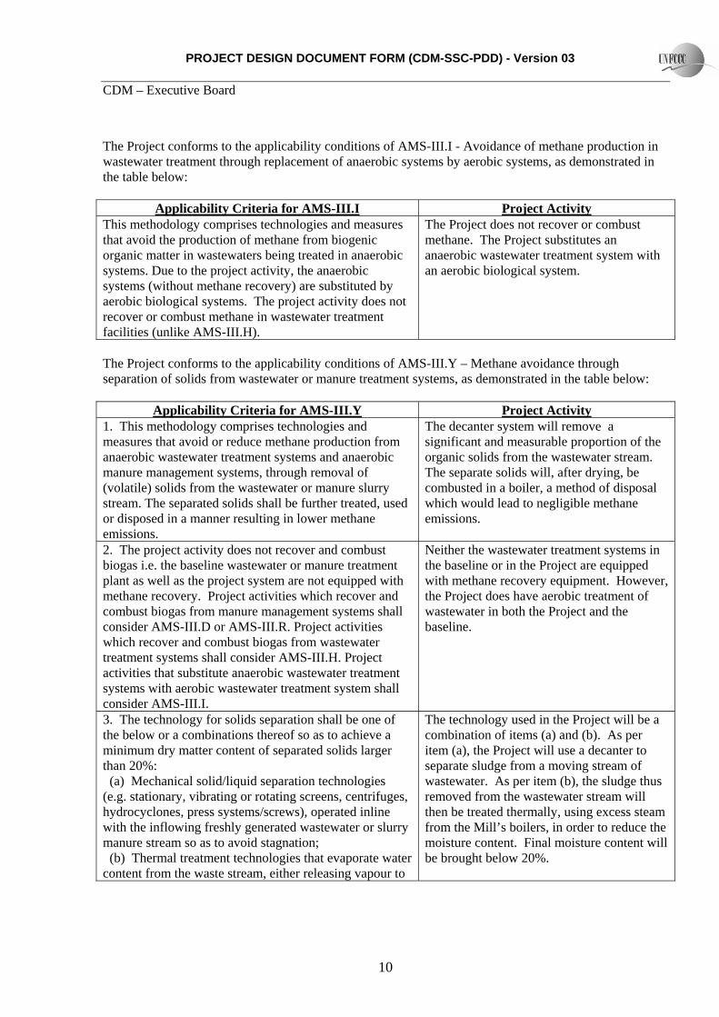
The Project conforms to the applicability conditions of AMS-III.I - Avoidance of methane production in wastewater treatment through replacement of anaerobic systems by aerobic systems, as demonstrated in the table below:
Applicability Criteria for AMS-III.I Project ActivityThis methodology comprises technologies and measures that avoid the production of methane from biogenic organic matter in wastewaters being treated in anaerobic systems. Due to the project activity, the anaerobic systems (without methane recovery) are substituted by aerobic biological systems. The project activity does not recover or combust methane in wastewater treatment facilities (unlike AMS-III.H).
The Project does not recover or combust methane. The Project substitutes an anaerobic wastewater treatment system with an aerobic biological system.
The Project conforms to the applicability conditions of AMS-III.Y – Methane avoidance through separation of solids from wastewater or manure treatment systems, as demonstrated in the table below:
Applicability Criteria for AMS-III.Y Project Activity1. This methodology comprises technologies and measures that avoid or reduce methane production from anaerobic wastewater treatment systems and anaerobic manure management systems, through removal of (volatile) solids from the wastewater or manure slurry stream. The separated solids shall be further treated, used or disposed in a manner resulting in lower methane emissions.
The decanter system will remove a significant and measurable proportion of the organic solids from the wastewater stream. The separate solids will, after drying, be combusted in a boiler, a method of disposal which would lead to negligible methane emissions.
2. The project activity does not recover and combust biogas i.e. the baseline wastewater or manure treatment plant as well as the project system are not equipped with methane recovery. Project activities which recover and combust biogas from manure management systems shall consider AMS-III.D or AMS-III.R. Project activities which recover and combust biogas from wastewater treatment systems shall consider AMS-III.H. Project activities that substitute anaerobic wastewater treatment systems with aerobic wastewater treatment system shall consider AMS-III.I.
Neither the wastewater treatment systems in the baseline or in the Project are equipped with methane recovery equipment. However, the Project does have aerobic treatment of wastewater in both the Project and the baseline.
3. The technology for solids separation shall be one of the below or a combinations thereof so as to achieve a minimum dry matter content of separated solids larger than 20%: (a) Mechanical solid/liquid separation technologies (e.g. stationary, vibrating or rotating screens, centrifuges, hydrocyclones, press systems/screws), operated inline with the inflowing freshly generated wastewater or slurry manure stream so as to avoid stagnation; (b) Thermal treatment technologies that evaporate water content from the waste stream, either releasing vapour to
The technology used in the Project will be a combination of items (a) and (b). As per item (a), the Project will use a decanter to separate sludge from a moving stream of wastewater. As per item (b), the sludge thus removed from the wastewater stream will then be treated thermally, using excess steam from the Mill’s boilers, in order to reduce the moisture content. Final moisture content will be brought below 20%.

PROJECT DESIGN DOCUMENT FORM (CDM-SSC-PDD) - Version 03 CDM – Executive Board
11
the atmosphere or condensing it into a liquid fraction (condensate) containing negligible volatile solids or COD load, resulting in a solid fraction. Examples include evaporation and spray drying technologies. 4. The dry matter content of separated solids shall remain higher than 20% throughout until its final disposal, destruction or use (e.g. spreading on the soil).
The dry matter content of the solid will be kept at or above 20% until combustion in the Mill’s biomass boiler. Note that there is a strong incentive to maintain the separated solid at as low a moisture level as possible, as this will ensure that the energy value of the solid remains high.
5. Separation of solids using gravity (settler tanks, ponds, or geotextile containers/bags) is not included in this methodology.
The decanting system, while making use of the principle of gravity, is fundamentally a mechanical treatment system which operates by moving the wastewater mechanically to promote the solid / liquid separation process.
6. In case of animal manure management systems the following conditions apply:
(a) Animals shall be managed in confined conditions; (b) No organic bedding material is used in the animal
barns or intentionally added to the manure stream; (c) If the baseline manure slurry was treated in an
anaerobic lagoon or another liquid treatment system, the outflow liquid from the lagoon was recycled as flush water or used to irrigate fields, however it was not discharged into river/lake/sea. In the latter case, i.e. effluent discharge into river/lake/sea, the system is considered as a wastewater treatment system and not a manure management system;
(d) A minimum interval of six months was observed between each removal of the solids accumulated in the lagoon.
The Project is not an animal manure management system, so this applicability condition is not relevant.
7. In case of wastewater treatment systems the following conditions apply:
(a) The baseline treatment systems do not include a fine solids separation process (i.e. grading smaller than 10 mm aperture, primary settlers, mechanical separation, etc.);
(b) In case the baseline treatment system was an anaerobic lagoon or a liquid system, a minimum interval of 30 days was observed between each removal of the solids accumulated in the lagoon.
The baseline treatment system does not include grading smaller than 10mm aperture, primary settlers or mechanical separation. Further, accumulated solids in the anaerobic ponds in the baseline was carried out at a much greater interval than 30 days – typical interval for sludge removal from the lagoons was once in 1 – 2 years, and for the initial cooling pond no sludge has been removed since 2003.
8. This methodology is not applicable when the project treats solids removed from an existing lagoon, or sludge originated from settlers or from any other biologically active treatment device of the baseline animal manure
The Project will be treating the fresh stream of wastewater from the Mill, and will not be treating any of the sludge or solids from an existing lagoon or tank.

PROJECT DESIGN DOCUMENT FORM (CDM-SSC-PDD) - Version 03 CDM – Executive Board
12
management/wastewater treatment system. 9. The separated solids shall be further treated, emissions resulting from further treatment, storage, use or disposal shall be considered. If the solids are combusted for thermal or heat generation, that component of the project activity can use a corresponding methodology under type I. If the solids are mechanically/thermally treated to produce refuse-derived fuel (RDF) or stabilized biomass (SB) the relevant provisions in AMS-III.E shall be followed. If the solids are used as animal feeds (e.g. feed to cows, pigs), any emissions from enteric fermentation and emissions from the manure, depending on the treatment system in those instances shall be considered as project emissions.
The separated solids will be combusted in the Mill’s biomass boilers. These boilers are already in place, and already use biomass as their primary fuel, so it will not be possible to claim any further emission reductions for the energy supplied by the boilers.
10. The liquid fraction from the project solid separation system shall be treated either in the baseline treatment facility or in a treatment system with a lower methane conversion factor (MCF) than the baseline system.
The liquid fraction will be sent to the aeration ponds, where it will be treated with more strictly managed process than in the baseline, leading to a lower MCF. The liquid will then be treated in the flocculent system, which again has a lower MCF than the baseline approach of releasing the wastewater into nearby waterways. Therefore, the overall MCF of subsequent treatment of the liquid will be demonstrably lower than that of the baseline.
The Project conforms to the applicability conditions of AMS-III.xx – Avoidance of methane emissions through from the chemical treatment of organic industrial wastewater, Version xx, as demonstrated in the table below:
Applicability Criteria for AMS-III.xx Project Activity1. This methodology comprises technologies and measures that avoid the production of methane from biogenic organic matter in wastewaters being treated in anaerobic systems. Due to the project activity, the anaerobic systems1 are replaced by chemical treatment systems based on the use of flocculents.
The project will take wastewater which is currently being treated anaerobically, and treat it using a flocculation process.
2. The flocculent-based wastewater treatment system should be designed so that retention time of the wastewater will be less than one day.
The maximum holding volume of the flocculation treatment system is around 5m3. Estimated throughflow of wastewater will be around 20-30 m3 per hour. Therefore retention time of the wastewater will be less than one hour.
1 As defined in 2006 IPCC Guidelines for National Greenhouse Gas inventories Volume 5, Chapter 6, Wastwater treatment and discharge, table 6.3 and 6.8. Under this methodology, anaerobic lagoons are ponds deeper than 2 meters, without aeration, ambient temperature above 15 degrees Centigrade, at least during part of the year, on a monthly average basis, and with a volumetric loading rate of Chemical Oxygen Demand above 0.1 kg COD/m3/day.
PROJECT DESIGN DOCUMENT FORM (CDM-SSC-PDD) - Version 03 CDM – Executive Board
13
3. This methodology may be used in combination with other methodologies (e.g. AMS-III.H, AMS-III.I, AMS-III.Y) to provide a comprehensive solution to wastewater treatment. In such cases, where the baseline emission, project emission or leakage calculations conflict or overlap, then the calculation approach which results in the most conservative estimation of the emission reductions should be selected.
The Project refers to AMS-III.I and AMS-III.Y as well as AMS-III.xx. Where the calculation approaches overlap, the more conservative option will be selected.
In addition, the Project conforms to the general requirement for AMS Type III methodologies that the emission reductions should be less than or equal to 60 kt CO2 equivalent annually. B.3. Description of the project boundary: In accordance with paragraph 3 of AMS-III.I, the project boundary for the project activity is defined as follows:
The project boundary is the physical, geographical sites where:
(a) The wastewater treatment would have taken place and the methane emission occurred in absence of the project activity;
(b) The wastewater treatment takes place in the project activity;
(c) The sludge is treated and disposed off in the baseline and project situation.
In accordance with paragraph 12 of AMS-III.Y, the project boundary for the project activity is defined as follows:
The project boundary is the physical, geographical site:
(a) Where the animal waste would have been collected, stored and treated and the methane emission would have occurred in the absence of the proposed project activity;
(b) Where the wastewater treatment would have taken place and the methane emission would have occurred in the absence of the proposed project activity;
(c) Where the treatment of animal waste or wastewater through solids separation takes place;
(d) Where the storage, gainful use, destruction and/or land application of the separated solids takes place;
(e) The itineraries between them, where the transportation of separated solids occur.
The illustration below shows the flowchart of the Project and its boundaries. In accordance with paragraph 5 of AMS-III.xx, the project boundary for the project activity is defined as follows: The Project Boundary is the physical, geographical sites where:

PROJECT DESIGN DOCUMENT FORM (CDM-SSC-PDD) - Version 03 CDM – Executive Board
14
(a) The wastewater treatment would have taken place and the methane emission occurred in absence of the project activity.
(b) The wastewater treatment takes place in the project activity (c) The sludge is treated and disposed of in the baseline situation (d) The solid waste extracted from the flocculation process is treated and disposed of in the project
situation The project boundary is shown on the following diagram:
B.4. Description of baseline and its development: The baseline scenario is in accordance with paragraph 4 of AMS-III.I: “The baseline scenario is the situation where, in the absence of the project activity, degradable organic matter is treated in anaerobic systems and methane is emitted to the atmposhere.” The baseline scenario is also in accordance with paragraph 13 of AMS-III.Y: “The baseline scenario is the situation where the solids separated from manure system or from the wastewater would be treated in the waster treatment or manure management system within the project boundary, without methane recovery, and methane is emitted to the atmosphere.” The baseline scenario is also in accordance with paragraph 6 of AMS-III.NEW: “The baseline scenario is the situation where, in the absence of the project activity, degradable organic matter is treated in anaerobic systems and methane is emitted to the atmosphere.”

PROJECT DESIGN DOCUMENT FORM (CDM-SSC-PDD) - Version 03 CDM – Executive Board
15
Currently at the Mill, wastewater is treated in a series of aerobic and anaerobic ponds. Finally, when the wastewater is released into a nearby waterway, it still contains a significant quantity of organic material. Further, sludge is periodically removed from both the aerobic and anaerobic wastewater treatment systems. This sludge is disposed in shallow pits / ponds adjacent to the wastewater treatment system. Please refer to Diagram B.4.I for a diagram of the current wastewater treatment system at the Mill. Under the CDM methodologies applied by the Project, appropriate baseline calculations are provided to estimate the baseline greenhouse gas emissions associated with: i. methane produced in the anaerobic baseline wastewater treatment systems ii. methane produced due to inefficiencies in the baseline aerobic wastewater treatment system iii. methane produced during the breakdown of remaining organic material in the wastewater following release to a natural body of water iv. methane produced during the treatment and disposal of sludge removed from the wastewater treatment system Diagram B.4.I
POM
POND1
POND
POND 3
Sludge Pit
CPO tank
Cooling Pond
POME tank
POND 4
Decanter Tank
Acid Tank 1
Acid Tank 2
AerationP d
Sbr Tank 2
River
Sbr Tank 1

PROJECT DESIGN DOCUMENT FORM (CDM-SSC-PDD) - Version 03 CDM – Executive Board
16
Given that this PDD uses several different technologies and combines 3 methodologies, we have used the chart below to compare how COD reductions are achieved in the baseline and in the Project. Diagram B.4.II
Well-managedaerobic PondMCF=0(AMS-III.I)
Anaerobic PondsMCF=0.8
Poorly managed aerobic pondsMCF = 0.3
Release to nearby Waterways MCF = 0.1
COD
77,000
20,000
1,770
0 0
COD
77,000DecanterMCF = 0(AMS.III.Y)
45,000
5,000FlocculationtreatmentMCF = 0(AMS-III.xx)
Baseline Project
50
Well-managedaerobic PondMCF=0(AMS-III.I)
Anaerobic PondsMCF=0.8
Poorly managed aerobic pondsMCF = 0.3
Release to nearby Waterways MCF = 0.1
COD
77,000
20,000
1,770
0 0
COD
77,000DecanterMCF = 0(AMS.III.Y)
45,000
5,000FlocculationtreatmentMCF = 0(AMS-III.xx)
Baseline Project
50
B.5. Description of how the anthropogenic emissions of GHG by sources are reduced below those that would have occurred in the absence of the registered small-scale CDM project activity: As a small scale project, the Project follows the instructions in Attachment A to Appendix B of the simplified modalities and procedures for small-scale CDM project activities (‘Attachment A’). According to Attachment A: “1. Project participants shall provide an explanation to show that the project activity would not have occurred anyway due to at least one of the following barriers: (a) Investment barrier: a financially more viable alternative to the project activity would have led to higher emissions; (b) Technological barrier: a less technologically advanced alternative to the project activity involves lower risks due to the performance uncertainty or low market share of the new technology adopted for the project activity and so would have led to higher emissions;

PROJECT DESIGN DOCUMENT FORM (CDM-SSC-PDD) - Version 03 CDM – Executive Board
17
(c) Barrier due to prevailing practice: prevailing practice or existing regulatory or policy requirements would have led to implementation of a technology with higher emissions; (d) Other barriers: without the project activity, for another specific reason identified by the project participant, such as institutional barriers or limited information, managerial resources, organizational capacity, financial resources, or capacity to absorb new technologies, emissions would have been higher.” In line with this guidance, the Project is subject to the following Barriers: 1. Investment barrier The project requires investment of around 150 million Japanese yen. The main costs breakdown as follows: Item Cost (JPY 000) Cost (USD)* 1. Consulting / project development costs 23,000 230,000 2. Capital investment 125,206 1,252,060 2.a Solid / liquid separation equipment 59,355 593,550 2.b Flocculent treatment system 13,500 1,350,000 2.c Equipment for drying of separated solids 34,370 343,700 2.d Ancillary equipment 11,259 112,590 2.e Design and other costs 6,722 67,220
Total 148,206 1,190,000 * Conversion rate of 1 USD = 100 JPY Further, operating costs are estimated as follows: Item Cost (JPY 000) Cost (USD)* 1. Maintenance costs 2,880 28,800 2. Flocculent procurement 4,049 40,490 3. Management costs 413 4,130 4. Insurance 990 9,900 4. (Full Overhaul in Year 3) 1,800** 18,000 Total 8,332 83,320 * Conversion rate of 1 USD = 100 JPY ** Not included in total Therefore, TEE will be making a significant initial investment to set up the wastewater treatment facility, and taking on a commitment to fund ongoing maintenance and operational costs. On the other hand, income from the Project will be zero. Therefore, without income from CERs, it is clear that the project will have no source of income. Unless an outside investor with an interest in procuring CERs, such as TEE, proposed to invest in the project, there is no commercial reason for this Project to be implemented. 2. Technology barrier The flocculent treatment developed for this project by TEE, with a patent pending, is the first known example of the use of flocculents in treatment of wastewater from palm oil mills in Malaysia. TEE’s operations to date have been entirely within the Japanese domestic market, for the most part providing

PROJECT DESIGN DOCUMENT FORM (CDM-SSC-PDD) - Version 03 CDM – Executive Board
18
environmental engineering support services for their parent company, Tokyo Electric Power Company. TEE would not therefore have been developing technology for wastewater treatment in an overseas market unless it were for the incentive of the CERs. 3. Prevailing practice barrier As explained in the technology barrier, this is the first known example of the use of flocculents in treatment of wastewater from palm oil mills in Malaysia. In addition, the use of decanters to separate liquid from solid waste is not a common practice in the palm oil industry, due to the installation and operating costs of a decanter, when compared to the relatively low-cost, low-maintenance approach of using anaerobic ponds. The project activity thus faces serious implementation barriers. The investment, technological and prevailing barriers enumerated above show that, in the absence of regulations preventing the alternatives, the Project is unlikely to be implemented without an additional form of revenue such as that available through the CDM. B.6. Emission reductions:
B.6.1. Explanation of methodological choices: General Approach In the baseline, treatment of the wastewater is currently conducted in two main phases: first, anaerobic lagoon treatment and second, poorly managed aerobic treatment. In the Project, wastewater treatment will be conducted in three phases: first, liquid / solid separation in a decanter; second, well-managed aerobic lagoon; and third, flocculation. However, the COD levels at each stage in the baseline will not correspond with COD levels at each stage in the Project. Further, each of these treatment processes requires use of a separate baseline methodology, each with its own set of calculation procedures. However, all 3 methodologies used by the Project base their baseline emission calculation on COD removal, and there are no significant differences in the calculation procedure. Therefore: - where the calculation in one or more methodologies is the same, the procedure from one
methodology only will be used for the ex ante calculation. - For ex post emission reduction calculations, the actual COD removal at each stage of the treatment
process will be monitored, and the sum of these values used. Baseline Emissions
Methane avoidance through separation of solids from wastewater Baseline emissions under AMS-III.Y are calculated in an identical manner to AMS-III.I, as set out below, and therefore it is not necessary to repeat the ex ante calculation in the PDD. However, for the ex post baseline calculation, it will be necessary to calculate the baseline emission for each treatment type, therefore for clarity, the calculation procedure used in AMS-III.Y is outlined here. Baseline emissions for AMS-III.Y shall be calculated based on the COD removal efficiency of the solids separation device. :
PROJECT DESIGN DOCUMENT FORM (CDM-SSC-PDD) - Version 03 CDM – Executive Board
19
BEy = Qi,y,ww ・ CODi,y,in ・ CODi,y,out ・ Bi,o,ww ・ MCFi,ww,treatment ・GWPCH4 / 1000 Where: Qww,m,y Volume of the wastewater treated by baseline wastewater treatment system i during the
months m, during year y, for the months with ambient average temperature above 15°C (m3)
i Index for baseline wastewater treatment systems, anaerobic lagoon and aerobic lagoon Bo,ww Methane producing capacity of the wastewater (IPCC lower value for domestic
wastewater of 0.21 kg CH4/kg COD) MCFanaerobic,i Methane correction factor for the anaerobic baseline wastewater treatment system i
replaced by the project activity, value as per table III.I. i . For deep anaerobic lagoon treatment system, MCF is 0.8. For the poorly managed aerobic treatment system, MCF is 0.3.
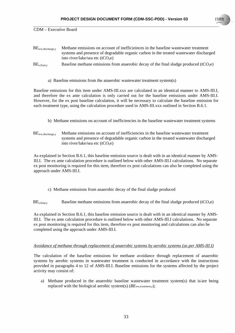
UFBL Model correction factor to account for model uncertainties (0.94)7 GWPCH4 Global Warming Potential for methane (value of 21) DF Campaign measurement discount is applied (0.89%) Avoidance of methane emissions through chemical treatment of organic industrial wastewater BEy = BEww,treatment,y + BEww,discharge,y + BEs,final,y Where: BEww,treatment,y Methane produced in the anaerobic baseline wastewater treatment system(s) that is/are
being replaced with the flocculent treatment system(s) (tCO2e) BEww,discharge,y Methane emissions on account of inefficieinces in the baseline wastewater treatment
systems and presence of degradable organic carbon in the treated wastewater discharged into river/lake/sea etc (tCO2e)
BEs,final,y Baseline methane emissions from anaerobic decay of the final sludge produced (tCO2e)
a) Baseline emissions from the anaerobic wastewater treatment system(s) Baseline emissions under AMS-III.xxx are calculated in an identical manner to AMS-III.I, as set out below, and therefore it is not necessary to repeat the ex ante calculation in the PDD. However, for the ex post baseline calculation, it will be necessary to calculate the baseline emission for each treatment type, therefore for clarity, the calculation procedure used in AMS-III.xxx is outlined here:
( ) 4,
,,,,,,,, ***** CHBLomi
ianaerobicymiremovedymwwytreatmentww GWPUFBMCFCODQBE ∑=
Qww,m,y Volume of the wastewater treated during the months m, during year y, for the months with ambient average temperature above 15 degrees C (m3)
PROJECT DESIGN DOCUMENT FORM (CDM-SSC-PDD) - Version 03 CDM – Executive Board
20
i Index for baseline wastewater treatment system CODremoved,i,y Chemical oxygen demand removed2 by the anaerobic wastewater treatment system i in
the baseline situation in the year y for the months m with ambient average temperature above 15 degrees C (tonnes/m3)
MCFanaerobic,i Methane correction factor for the anaerobic baseline wastewater treatment system i replaced by the project activity, value as per table III.xx.1
BBo,ww Methane producing capacity for the wastewater (IPCC default value for domestic wastewater of 0.21 kg CH4/kg COD ) 3
UFBL Model correction factor to account for model uncertainties (0.94)4
GWPCH4 Global Warming Potential for CH4 (value of 21) To determine CODremoved,i,m,y: as the baseline treatment system(s) is different from the treatment system(s) in the project scenario, the monitored values of the COD inflow during the crediting period will be used to calculate the baseline emissions ex post. The COD removed by the baseline system(s) shall be based on the removal efficiency of the baseline systems estimated in this case in accordance with the procedures set out in AMS-III.Y. b) Methane emissions on account of inefficieinces in the baseline wastewater treatment systems BEww,discharge,y Methane emissions on account of inefficieinces in the baseline wastewater treatment
systems and presence of degradable organic carbon in the treated wastewater discharged into river/lake/sea etc (tCO2e)
This baseline emission source is dealt with in an identical manner by AMS-III.I. The ex ante calculation procedure is outlined below with other AMS-III.I calculations. No separate ex post monitoring is required for this item, therefore ex post calculations can also be completed using the approach under AMS-III.I.
c) Methane emissions from anaerobic decay of the final sludge produced BEs,final,y Baseline methane emissions from anaerobic decay of the final sludge produced (tCO2e) This baseline emission source is dealt with in an identical manner by AMS-III.I. The ex ante calculation procedure is outlined below with other AMS-III.I calculations. No separate ex post monitoring is required for this item, therefore ex post calculations can also be completed using the approach under AMS-III.I. Avoidance of methane through replacement of anaerobic systems by aerobic systems
2 Difference of inflow COD and the outflow COD. 3 The IPCC default value of 0.25 kg CH4/kg COD was corrected to take into account the uncertainties. For domestic wastewater, a COD based value of Bo.ww can be converted to BOD5 based value by dividing it by 2.4 i.e. a default value of 0.504 kg CH4/kg BOD can be used. 4 Reference: FCCC/SBSTA/2003/10/Add.2, page 25.
PROJECT DESIGN DOCUMENT FORM (CDM-SSC-PDD) - Version 03 CDM – Executive Board
21
The calculation of the baseline emissions for methane avoidance through replacement of anaerobic systems by aerobic systems in wastewater treatment is conducted in accordance with the instructions provided in paragraphs 4 to 12 of AMS-III.I. Baseline emissions for the systems affected by the project activity may consist of:
a) Methane produced in the anaerobic baseline wastewater treatment system(s) that is/are being replaced with the biological aerobic system(s) (BEww,treatment,y);
b) Methane emissions on account of inefficiencies in the baseline wastewater treatment systems and presence of degradable organic carbon in the treated wastewater discharged into river/lake/sea etc. (BEww,discharge,y);
c) Methane produced in the baseline sludge treatment system(s) (BEs,treatment,y); d) Methane emissions from anaerobic decay of the final sludge produced in the baseline situation. If
the sludge is controlled combusted, disposed in a landfill with biogas recovery, or used for soil application in the baseline scenario, this term shall be neglected (BEs,final,y)
Baseline emissions in the year y
yfinalsytreatmentsyedischwwytreatmentwwy BEBEBEBEBE ,,,,,arg,,, +++=
Where: BEy Baseline emissions in the year y (tCO2e) BEww,treatment,y Methane produced in the anaerobic baseline wastewater treatment system(s) that
is/are being replaced with the biological aerobic system(s) (tCO2e) BEww,discharge,y Methane emissions on account of inefficiencies in the baseline wastewater
treatment systems and presence of degradable organic carbon in the treated wastewater discharged into river/lake/sea etc. (tCO2e)
BEs,treatment,y Methane produced in the baseline sludge treatment system(s) (tCO2e) BEs,final,y Baseline methane emissions from anaerobic decay of the final sludge produced
(tCO2e) a) Methane produced in the anaerobic baseline wastewater treatment system(s) that is/are being
replaced with the biological aerobic system(s) (BEww,treatment,y);
( ) DFGWPUFBMCFCODQBE CHBLOmj
ianaerobicymiremovedymwwytreatmentww ****** 4,
,,,,,,,, ∑=
Where: Qww,m,y Volume of the wastewater treated by baseline wastewater treatment system i during the
months m, during year y, for the months with ambient average temperature above 15°C (m3)
i Index for baseline wastewater treatment systems, anaerobic lagoon and aerobic lagoon Bo,ww Methane producing capacity of the wastewater (IPCC lower value for domestic
wastewater of 0.21 kg CH4/kg COD) MCFanaerobic,i Methane correction factor for the anaerobic baseline wastewater treatment system i
replaced by the project activity, value as per table III.I. i . For deep anaerobic lagoon treatment system, MCF is 0.8. For the poorly managed aerobic treatment system, MCF is 0.3.

PROJECT DESIGN DOCUMENT FORM (CDM-SSC-PDD) - Version 03 CDM – Executive Board
22
UFBL Model correction factor to account for model uncertainties (0.94)7 GWPCH4 Global Warming Potential for methane (value of 21) DF Campaign measurement discount is applied (0.89%)
b) Methane emissions on account of inefficiencies in the baseline wastewater treatment systems and
presence of degradable organic carbon in the treated wastewater discharged into river/lake/sea etc. (BEww,discharge,y);
DFMCFCODUFBGWPQBE edischBLwwyBLedischwwBLwwoCHywwyedischww ******
arg,,,,arg,,4,,arg, =
Where: Qww,y Volume of treated wastewater discharged in year y (m3) UFBL Model correction factor to account for model uncertainties (0.94)7 MCFww,discharge,BL Methane correction factor based on the discharge (MCF value of 0.1 as per table
III.I.1) Bo,ww Methane producing capacity of the wastewater (IPCC lower value for domestic
wastewater of 0.21 kg CH4/kg COD) GWPCH4 Global Warming Potential for methane (value of 21) DF Campaign measurement discount is applied (0.89%)
c) Methane produced in the baseline sludge treatment system(s) (BEs,treatment,y)
The Project is treating wastewater, not sludge, therefore baseline emissions from this source need not be considered.
d) Methane emissions from anaerobic decay of the final sludge produced in the baseline situation. If
the sludge is controlled combusted, disposed in a landfill with biogas recovery, or used for soil application in the baseline scenario, this term shall be neglected ().
In the baseline, sludge is simply removed from the ponds when necessary, and placed in a waste disposal site in the POM’s grounds, where it decomposes in anaerobic conditions. Baseline emissions from this source are calculated as follows:
DFF GWPDOCMCFUFDOCSBE CHFfinalBLSBLSyBLfinalyfinalS **12/16******4,,,,,, =
Where: Sfinal,BL,y Amount of dry matter in final sludge generated by the baseline wastewater treatment in
the year y (tonnes). It will be estimated using the monitored amount of dry matter in final sludge generated by the project activity (Sfinal,PJ,y) corrected for the sludge generation ratios of the project and baseline systems as per formula 6 in AMS-III.G.
DOCs Degradable organic content of the untreated sludge generated in the year y (fraction, dry basis). Default value of 0.5 is applied
UFBL Model correction factor for uncertainties (0.94) MCFs,BL,final Methane correction factor for the baseline sludge treatment system j (MCF values of 0.8
in accordance to AMS-III.G )
PROJECT DESIGN DOCUMENT FORM (CDM-SSC-PDD) - Version 03 CDM – Executive Board
23
DOCF Fraction of DOC dissimilated to biogas (IPCC default value of 0.5) F Fraction of CH4 in biogas (IPCC default of 0.5)
Project emissions Methane avoidance through separation of solids from wastewater Project activity emissions under AMS-III.Y are as follows: PEy = PEy,ss + PEy, power + PEy,trans Where: Pey,ss, Project emissions from storage, use, destruction or disposal of solids separated in year y
(tCO2e) PE y power Project emissions from energy use for pumping and/or operating the separation device in
year y (tCO2e), calculated as per AMS-I.D methods PEy,trans Project emissions for incremental transportation of solids in the project scenario, beyond
the emissions for transportation of solids in the baseline scenario (tCO2e)
(a) Any methane emissions from storage, use, disposal or destruction of solids separated;
The solids separated from the POME by the decanter will be immediately dried and then combusted in the POM’s biomass boiler, in a continuous process. Solids will not be stored for more than 14 days, making any potential methane emissions from this source negligible. Project emissions from this source will therefore be negligible. However, monitoring of this process will take place to ensure that all solids separate are disposed of in this way.
(b) Emissions from electricity and fossil fuel use by the solid separation technology including pumping of slurry manure and heat supply for spray drying/evaporation, calculated as per the methods of AMS-I.D;
The POM’s biomass boiler and associated turbine can provide ample electricity and steam for the operation of the decanter and for the drying process. As this energy comes from a biomass source, no emissions need to be considered here. In fact the separated solid will be contributing to this energy supply, as it will be combusted in the boiler, and provide a supplementary carbon neutral fuel for the POM, although no emission reductions are claimed for this. Nonetheless, the amount of electricity consumed by the Project will be monitored, and in case of contingency use of fossil fuels to provide energy for the Project, these fossil fuels will be monitored and appropriate project emissions calculated as per the requirements of AMS-I.D.
(c) Incremental CO2 emissions due to increased transportation (PEy,transp):
I Transportation of solids to sites where it will be treated further or gainfully used (within the project boundary);
PROJECT DESIGN DOCUMENT FORM (CDM-SSC-PDD) - Version 03 CDM – Executive Board
24
II Transportation of solids from and to treatment facilities to storage sites (within the project boundary);
III Transportation of solids to disposal site.
The separated solids will all be treated and combusted on-site, so no transportation emissions will occur.
Avoidance of methane emissions through chemical treatment of organic industrial wastewater Project activity emissions under AMS-III.xxx consist of: PEy = PEpower,y + PEww,discharge,y + PEfloc,y
Where: PEy Project activity emissions in year y (tCO2e) PEpower,y Emissions on account of electricity or fossil fuel consumption in the year y
(tCO2e) PEww,discharge,y Methane emissions on account of inefficiencies in the project wastewater
treatment systems and presence of degradable organic carbon in the treated wastewater discharged into river/lake/sea etc (tCO2e)
PEfloc,y Methane emissions produced in the treatment of the solid material extracted from the wastewater through the flocculation treatment process used in the project activity (tCO2e)
(a) CO2 emission related to the power and fossil fuel used by the project activity facilities (PEpower,y);
The POM’s biomass boiler and associated turbine can provide ample electricity for the operation of the flocculation and solid/liquid separation equipment. As this energy comes from a biomass source, no emissions need to be considered here. In fact the separated solid will be contributing to this energy supply, as it will be combusted in the boiler, and provide a supplementary carbon neutral fuel for the POM, although no emission reductions are claimed for this. Nonetheless, the amount of electricity consumed by the Project will be monitored, and in case of contingency use of fossil fuels to provide energy for the Project, these fossil fuels will be monitored and appropriate project emissions calculated as per the requirements of AMS-I.D.
(b) Methane emissions from degradable organic carbon in treated wastewater discharged in sea /
river or lake (PEww,discharge,y); The flocculation process will reduce degradable organic carbon to extremely low levels, therefore emissions from this source will be extremely small. Nonetheless, it is considered conservative to calculate emissions from this source, and the approach set out in the methodology will be used, as follows:
4,arg,,,arg,,,arg, ***** CHPJoPJedischwwyPJedischwwywwyedischww GWPUFBMCFCODQPE =

PROJECT DESIGN DOCUMENT FORM (CDM-SSC-PDD) - Version 03 CDM – Executive Board
25
Where: Qww,y Volume of treated wastewater discharged in year y (m3) UFPJ Model correction factor to account for model uncertainties (0.94)5
CODww,discharge,PJ,y Chemical oxygen demand of the treated wastewater discharged into sea, river or lake in the project in year y (tonnes/m3)
MCFww,discharge,PJ Methane correction factor based on the discharge pathway (e.g. into sea, river or lake) of the wastewater (fraction) (MCF as per table III.xx.1)
(c) Methane emissions from treatment of the solid waste (sludge) extracted in the flocculation treatment in the project activity (PEfloc,y)
The sludge separated from the POME through flocculation will be dried and then combusted in the POM’s biomass boiler, in a continuous process, together with solids retrieved in the decanter. Sludge will not be stored for more than 14 days, making any potential methane emissions from this source negligible. Project emissions from this source will therefore be negligible. However, monitoring of this process will take place to transparently show that all solids separated are disposed of in this way.
In case any of the dried sludge cannot be combusted in the POM’s boiler, project emissions from this source will be calculated as follows:
4,,,,, *12/16****** CHFPJflocktreatmentflock
yPJkyfloc GWPFDOCUFDOCMCFFlocPE ∑=
Where: Flock,PJ,y Amount of dry matter in the flocculated sludge removed from the flocculent
treatment system k in the project activity (tonne) k Index for project flocculent treatment system DOCfloc Degradable organic content of the flocculated sludge generated in the year y
(fraction, dry basis). It shall be estimated using default values of 0.5 for domestic sludge and 0.257 for industrial sludge.6
MCFfloc,treatment,k Methane correction factor for the flocculent treatment system k (MCF values as per table III.xx.1)
UFPJ Model correction factor to account for model uncertainties (1.06)7
DOCF Fraction of COD dissimilated to biogas (IPCC default value of 0.5) F Fraction of CH4 in biogas (IPCC default of 0.5) Avoidance of methane through replacement of anaerobic systems by aerobic systems In accordance to paragraphs 13 of AMS-III.I, project activity emissions consist of: 5 Reference: FCCC/SBSTA/2003/10/Add.2, page 25. 6 The IPCC default values of 0.05 for domestic sludge (wet basis, considering a default dry matter content of 10 percent) or 0.09 for industrial sludge (wet basis, assuming dry matter content of 35 percent), were corrected for dry basis. 7 Reference: FCCC/SBSTA/2003/10/Add.2, page 25.
PROJECT DESIGN DOCUMENT FORM (CDM-SSC-PDD) - Version 03 CDM – Executive Board
26
PEy = PEpower,y + PEww,treatment,y + PEww,discharge,y + PEs,l,y Where: PEpower,y CO2 emissions related to the power and fossil fuel used by the project activity facilities in
year y (tCO2e) PEww,treatment,y Methane emissions during the treatment of the wastewater in biological aerobic
wastewater treatment systems in year y (tCO2e) PEww,discharge,y Methane emissions from degradable organic carbon in treated wastewater discharged in
sea/river or lake in year y (tCO2e) PEs,l,y Methane emissions from sludge treatment in the project activity in year from treatment
process i in year y (tCO2e) PEs,final,y Methane emissions from the decay of the final sludge generated by the project activity, if
the sludge is disposed to decay anaerobically in a landfill without methane recovery in year y (tCO2e)
a) CO2 emissions related to the power and fossil fuel used by the project activity facilities
(PEpower,y);
The POM’s biomass boiler and associated turbine already provide electricity for the operation of the poorly managed aerobic treatment system in the baseline. There is also ample capacity for the more thorough aerobic treatment to be carried out in the Project. As this energy comes from a biomass source, no emissions need to be considered here. Nonetheless, the amount of electricity consumed by the Project will be monitored, and in case of contingency use of fossil fuels to provide energy for the Project, these fossil fuels will be monitored and appropriate project emissions calculated as per the following calculation:
EFNCVFPE yfuelfossiljynconsumptioyyelectricit ,,, **=
Where: Fconsumption,y amount of each fossil fuel i combusted to provide energy to the Project in year y (t). NCVi Net Calorific Value of each fuel i combusted (GJ/t) EFfossil fuel,i,y emission factor of each fossil fuel i combusted (tCO2/GJ)
b) Methane emissions during the treatment of the wastewater in biological aerobic wastewater
treatment systems (PEww,treatment,y);
These emissions are calculated as per formula 9 in paragraph 15 of AMS-III.I. In the Project, the corresponding MCFaerobic,k parameter would be 0.0 (zero) as per MCF values in table III.H.1, as the effluent from the decanters will be treated in a well managed aerobic facility. Nonetheless, the aerobic treatment process will be monitored, and if it fails to meet the criteria for ‘well-managed aerobic facility’, project emissions will be calculated as follows:
PROJECT DESIGN DOCUMENT FORM (CDM-SSC-PDD) - Version 03 CDM – Executive Board
27
( ) GWPUFBMCFCODQPE CHPJwwOk
kaerobicykremovedykwwytreatmentww 4,,,,,,,, *****∑=
Where: Qww,k,y Volume of the wastewater treated during the year y (m3) CODremoved,k,y Amount of COD removed by the aerobic treatment facility (t) MCFaerobic,k Methane Conversion Factor of the aerobic treatment facility, as per MCF values
in table III.H.1. BBo,ww Methane producing capacity for the wastewater (IPCC default value for domestic
wastewater of 0.21 kg CH4/kg COD) UFPJ Model correction factor to account for model uncertainties (1.06) GWPCH4 Global Warming Potential for CH4 (value of 21)
c) Methane emissions from degradable organic carbon in treated wastewater discharged in sea/river or lake (PEww,discharge,y);
The effluent from the aerobic treatment facility will be further processed by the flocculant treatment system. The final wastewater released by the flocculant treatment system will have its COD measured, and appropriate project emissions will be calculated as per the requirements of AMS-III.xxx, but it will not be necessary to account for this emission source under AMS-III.I.
d) Methane emissions from sludge treatment in the project activity (PEs,l,y);
The project emissions from that sludge treatment will be calculated as per formula 11 in paragraph 17 of AMS-III.I. Any sludge excavated from the aerobic ponds in the Project will be treated in the same way as solids removed in the decantering and flocculation processes – i.e. the sludge will be first dried, using energy supplied by the POM’s biomass boiler, and then combusted in the POM’s boiler. Alternatively, some of the sludge may, after drying, be used for land application, in small quantities which will not enable the creation of an anaerobic environment. The treatment of such sludge will be monitored, and an MCF of 0.0 (zero) will be applied.
GWPDOCUFDOCMCFSPE CHFPJsjPJtreatments
jyPJjytreatments F
4,,,,,,, *12/16****∗∗= ∑
Where: Sj,,PJ,y Amount of dry matter in the sludge treated by the sludge treatment system j in
year y (tonnes) MCFs,treatment,PJ,y Methane Conversion Factor of the aerobic treatment facility, as per MCF values
in table III.H.1. DOCs Degradable organic content of the sludge generated in the year y (fraction, dry
basis). It shall be estimated using default values of 0.5 for domestic sludge and 0.257 for industrial sludge.
UFPJ Model correction factor to account for model uncertainties (1.06)

PROJECT DESIGN DOCUMENT FORM (CDM-SSC-PDD) - Version 03 CDM – Executive Board
28
DOCF Fraction of COD dissimilated to biogas (IPCC default value of 0.5) F Fraction of CH4 in biogas (IPCC default of 0.5) GWPCH4 Global Warming Potential for CH4 (value of 21)
e) Methane emissions from the decay of the final sludge generated by the project activity, if the sludge is disposed to decay anaerobically in a landfill without methane recovery (PEs,final,y).
Project emissions from this source are included in the calculation of project emissions from sludge treatment PEs,l,y above, therefore the projects emission is zero. Leakage Methane avoidance through separation of solids from wastewater If the solid separation technology is equipment transferred from another activity leakage effects are to be considered. In the case of the project, no equipment will be transferred from another activity, therefore emissions from this source can be considered as zero. Avoidance of methane emissions through chemical treatment of organic industrial wastewater The portion of the flocculent which is determined to be from a Manufactured Source should be considered as a potential source of leakage emissions. Such leakage emissions are to be calculated according to the following formula:
∑=i
imanufflocymanufflocy EFQLeakage ,,,, *
where Qfloc,manuf,y is the quantity of flocculent consumed by the project activity and considered as being from a
Manufactured Source in year y i is the index for each constituent of the flocculent which is considered to be from a
Manufactured Source EFfloc,manuf,i is the emission factor for the manufacturing process of each constituent of the flocculent i
considered to be from a Manufactured Source. A default emission factor of 7.9 tCO2e / t is to be applied.
Avoidance of methane through replacement of anaerobic systems by aerobic systems In AMS-III.I, if the aerobic treatment technology is equipment transferred from another activity or if the existing equipment is transferred to another activity, leakage effects at the site of the other activity are to be considered. In the case of the project, no equipment will be transferred from another activity, therefore emissions from this source can be considered as zero.
B.6.2. Data and parameters that are available at validation: (Copy this table for each data and parameter)

PROJECT DESIGN DOCUMENT FORM (CDM-SSC-PDD) - Version 03 CDM – Executive Board
29
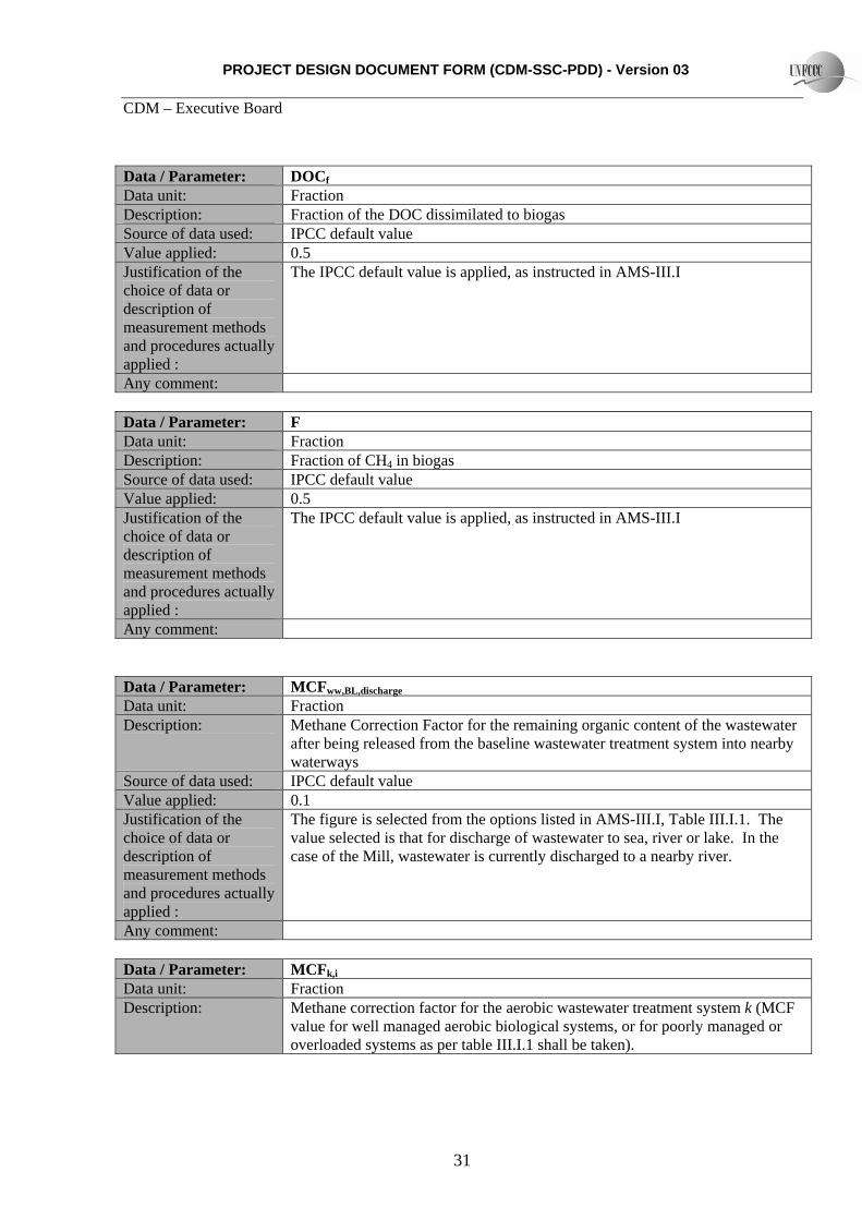
The following parameters are required by AMS-III.I Data / Parameter: MCFanaerobic,i
Data unit: Fraction Description: Methane Correction Factor for the baseline wastewater treatment system Source of data used: IPCC default value Value applied: 0.8 Justification of the choice of data or description of measurement methods and procedures actually applied :
The figure is selected from the options listed in AMS-III.I, Table III.I.1. The value selected is that for anaerobic deep lagoons (depth more than 2 metres). The Mill has 4 anaerobic lagoons, all of which are more than 2 metres in depth.
Any comment:
Data / Parameter: BB0,ww
Data unit: kgCH4 / kg COD Description: Methane producing capacity for the wastewater Source of data used: IPCC default value Value applied: 0.21 Justification of the choice of data or description of measurement methods and procedures actually applied :
This value is applied as per the instructions in the Methodology. As per AMS-III.I, IPCC default value of 0.25kgCH4 / kg COD was corrected to take into account uncertainties.
Any comment:
Data / Parameter: UFBL
Data unit: Fraction Description: Uncertainty factor used in the Baseline calculations Source of data used: IPCC default value Value applied: 0.94 Justification of the choice of data or description of measurement methods and procedures actually applied :
Default value applied as per the instructions in AMS-III.I
Any comment:
Data / Parameter: GWPCH4
Data unit: tCO2e / tCH4
Description: Global Warming Potential of methane Source of data used: IPCC default value Value applied: 21 Justification of the Default value applied as per the instructions in AMS-III.I

PROJECT DESIGN DOCUMENT FORM (CDM-SSC-PDD) - Version 03 CDM – Executive Board
30
choice of data or description of measurement methods and procedures actually applied : Any comment:
Data / Parameter: Sj,BL,y Data unit: tonnes Description: Mass of sludge removed in the baseline from treatment process j in year y Source of data used: The amount of sludge removed from the ponds was recorded by the POM Value applied: 6000 Justification of the choice of data or description of measurement methods and procedures actually applied :
Subsequent samples of the wastewater indicate that the amount of solids suspended in the wastewater tally with the level of sludge production recorded by the POM.
Any comment:
Data / Parameter: MCFs,treatment
Data unit: Fraction Description: Methane Correction Factor for the baseline sludge treatment system Source of data used: IPCC default value Value applied: 0.8 Justification of the choice of data or description of measurement methods and procedures actually applied :
The figure is selected from the options listed in AMS-III.I, Table III.I.1. The value selected is that for anaerobic deep lagoons (depth 3 - 4 metres). The Mill has 2 ponds which are used as a dumping site for the sludge that is periodically removed from the anaerobic and aerobic ponds.
Any comment:
Data / Parameter: DOCs
Data unit: Fraction (dry basis) Description: Degradable organic content of the untreated sludge generated in the baseline Source of data used: IPCC Default Value Value applied: 0.257 Justification of the choice of data or description of measurement methods and procedures actually applied :
The figure used is the default value for industrial sludge given in AMS-III.I
Any comment:
PROJECT DESIGN DOCUMENT FORM (CDM-SSC-PDD) - Version 03 CDM – Executive Board
31
Data / Parameter: DOCf
Data unit: Fraction Description: Fraction of the DOC dissimilated to biogas Source of data used: IPCC default value Value applied: 0.5 Justification of the choice of data or description of measurement methods and procedures actually applied :
The IPCC default value is applied, as instructed in AMS-III.I
Any comment:
Data / Parameter: F Data unit: Fraction Description: Fraction of CH4 in biogas Source of data used: IPCC default value Value applied: 0.5 Justification of the choice of data or description of measurement methods and procedures actually applied :
The IPCC default value is applied, as instructed in AMS-III.I
Any comment:
Data / Parameter: MCFww,BL,discharge
Data unit: Fraction Description: Methane Correction Factor for the remaining organic content of the wastewater
after being released from the baseline wastewater treatment system into nearby waterways
Source of data used: IPCC default value Value applied: 0.1 Justification of the choice of data or description of measurement methods and procedures actually applied :
The figure is selected from the options listed in AMS-III.I, Table III.I.1. The value selected is that for discharge of wastewater to sea, river or lake. In the case of the Mill, wastewater is currently discharged to a nearby river.
Any comment:
Data / Parameter: MCFk,i
Data unit: Fraction Description: Methane correction factor for the aerobic wastewater treatment system k (MCF
value for well managed aerobic biological systems, or for poorly managed or overloaded systems as per table III.I.1 shall be taken).

PROJECT DESIGN DOCUMENT FORM (CDM-SSC-PDD) - Version 03 CDM – Executive Board
32
Source of data used: Default value used as instructed in the methodology Value applied: 0 Justification of the choice of data or description of measurement methods and procedures actually applied :
The project aerobic system is well managed and will be handling an appropriate load of wastewater to ensure maintenance of an aerobic environment.
Any comment:
Data / Parameter: UFPJ
Data unit: Fraction Description: Model correction factor to account for model uncertainties Source of data used: Default value used as instructed in the methodology Value applied: 1.06 Justification of the choice of data or description of measurement methods and procedures actually applied :
Value applied as instructed in the methodology
Any comment: B.6.3 Ex-ante calculation of emission reductions:
Baseline
Methane avoidance through separation of solids from wastewater Baseline emissions under AMS-III.Y are calculated in an identical manner to AMS-III.I, and therefore the ex ante calculation is only carried out for the baseline emissions under AMS-III.I. However, for the ex post baseline calculation, it will be necessary to calculate the baseline emission for each treatment type, using the calculation procedure used in AMS-III.Y outlined in Section B.6.1. Methane avoidance through flocculation of organic solids from industrial wastewater BEy = BEww,treatment,y + BEww,discharge,y + BEs,final,y Where: BEww,treatment,y Methane produced in the anaerobic baseline wastewater treatment system(s) that is/are
being replaced with the flocculent treatment system(s) (tCO2e)
PROJECT DESIGN DOCUMENT FORM (CDM-SSC-PDD) - Version 03 CDM – Executive Board
33
BEww,discharge,y Methane emissions on account of inefficieinces in the baseline wastewater treatment systems and presence of degradable organic carbon in the treated wastewater discharged into river/lake/sea etc (tCO2e)
BEs,final,y Baseline methane emissions from anaerobic decay of the final sludge produced (tCO2e)
a) Baseline emissions from the anaerobic wastewater treatment system(s) Baseline emissions for this item under AMS-III.xxx are calculated in an identical manner to AMS-III.I, and therefore the ex ante calculation is only carried out for the baseline emissions under AMS-III.I. However, for the ex post baseline calculation, it will be necessary to calculate the baseline emission for each treatment type, using the calculation procedure used in AMS-III.xxx outlined in Section B.6.1. b) Methane emissions on account of inefficiencies in the baseline wastewater treatment systems BEww,discharge,y Methane emissions on account of inefficiencies in the baseline wastewater treatment
systems and presence of degradable organic carbon in the treated wastewater discharged into river/lake/sea etc (tCO2e)
As explained in Section B.6.1, this baseline emission source is dealt with in an identical manner by AMS-III.I. The ex ante calculation procedure is outlined below with other AMS-III.I calculations. No separate ex post monitoring is required for this item, therefore ex post calculations can also be completed using the approach under AMS-III.I.
c) Methane emissions from anaerobic decay of the final sludge produced BEs,final,y Baseline methane emissions from anaerobic decay of the final sludge produced (tCO2e) As explained in Section B.6.1, this baseline emission source is dealt with in an identical manner by AMS-III.I. The ex ante calculation procedure is outlined below with other AMS-III.I calculations. No separate ex post monitoring is required for this item, therefore ex post monitoring and calculations can also be completed using the approach under AMS-III.I. Avoidance of methane through replacement of anaerobic systems by aerobic systems (as per AMS-III.I) The calculation of the baseline emissions for methane avoidance through replacement of anaerobic systems by aerobic systems in wastewater treatment is conducted in accordance with the instructions provided in paragraphs 4 to 12 of AMS-III.I. Baseline emissions for the systems affected by the project activity may consist of:
a) Methane produced in the anaerobic baseline wastewater treatment system(s) that is/are being replaced with the biological aerobic system(s) (BEww,treatment,y);

PROJECT DESIGN DOCUMENT FORM (CDM-SSC-PDD) - Version 03 CDM – Executive Board
34
b) Methane emissions on account of inefficiencies in the baseline wastewater treatment systems and presence of degradable organic carbon in the treated wastewater discharged into river/lake/sea etc. (BEww,discharge,y);
c) Methane produced in the baseline sludge treatment system(s) (BEs,treatment,y); d) Methane emissions from anaerobic decay of the final sludge produced in the baseline situation. If
the sludge is controlled combusted, disposed in a landfill with biogas recovery, or used for soil application in the baseline scenario, this term shall be neglected (BEs,final,y)
Expressed as:
yfinalsytreatmentsyedischwwytreatmentwwy BEBEBEBEBE ,,,,,arg,,, +++=
Where:
BEy Baseline emissions in the year y (tCO2e) BEww,treatment,y Methane produced in the anaerobic baseline wastewater treatment system(s) that is/are
being replaced with the biological aerobic system(s) (tCO2e) BEww,discharge,y Methane emissions on account of inefficiencies in the baseline wastewater treatment
systems and presence of degradable organic carbon in the treated wastewater discharged into river/lake/sea etc. (tCO2e)
BEs,treatment,y Methane produced in the baseline sludge treatment system(s) (tCO2e) BEs,final,y Baseline methane emissions from anaerobic decay of the final sludge produced (tCO2e)
a) Methane produced in the anaerobic baseline wastewater treatment system(s) that is/are being replaced with the biological aerobic system(s) (BEww,treatment,y);
( ) DFGWPUFBMCFCODQBE CHBLOmj
ianaerobicymiremovedymwwytreatmentww ******4
,,,,,,,,, ∑=
Where: Qww,m,y Volume of the wastewater treated by baseline wastewater treatment system i during the
months m, during year y, for the months with ambient average temperature above 15°C (m3)
i Index for baseline wastewater treatment systems, anaerobic lagoon and aerobic lagoon Bo,ww Methane producing capacity of the wastewater (IPCC lower value for domestic
wastewater of 0.21 kg CH4/kg COD) MCFanaerobic,i Methane correction factor for the anaerobic baseline wastewater treatment system i
replaced by the project activity, value as per table III.I i . For deep anaerobic lagoon treatment system, MCF is 0.8. For the poorly managed aerobic treatment system, MCF is 0.3.
UFBL Model correction factor to account for model uncertainties (0.94)7 GWPCH4 Global Warming Potential for methane (value of 21) DF Campaign measurement discount is applied (0.89%) Calculation for baseline anaerobic ponds:

PROJECT DESIGN DOCUMENT FORM (CDM-SSC-PDD) - Version 03 CDM – Executive Board
35
BEww,treatment,y = Qww,m,y *
CODremo
ved,i,m,
* MCFana
erobic
* Bo,ww * UFBL * GWPCH4
* DF
m3 kgCOD/m3
kgCH4/kgCOD
145,302 * 73.48 * 0.3 * 0.21 * 0.94 * 21 0.89
BEww,treatment,y = 31,513,000 kgCO2e
= 31,513 tCO2e
Calculation for baseline poorly managed aerobic ponds: BEww,treatment,y = Qww,m,y *
CODremo
ved,i,m,
* MCFana
erobic
* Bo,ww * UFBL * GWPCH4
* DF
m3 kgCOD/m3
kgCH4/kgCOD
145,302 * 3.13 * 0.3 * 0.21 * 0.94 * 21 0.89
BEww,treatment,y = 503,000 kgCO2e
= 503 tCO2e
Total BEww,treatment,y = 31,513 + 503 = 32,016
b) Methane emissions on account of inefficiencies in the baseline wastewater treatment systems and presence of degradable organic carbon in the treated wastewater discharged into river/lake/sea etc. (BEww,discharge,y);
DFMCFCODUFBGWPQBE edischBLwwyBLedischwwBLwwoCHywwyedischww ******
arg,,,,arg,,4,,arg, =
Where: Qww,y Volume of treated wastewater discharged in year y (m3) UFBL Model correction factor to account for model uncertainties (0.94)7 MCFww,discharge,BL Methane correction factor based on the discharge (MCF value of 0.1 as per table
III.I.1) Bo,ww Methane producing capacity of the wastewater (IPCC lower value for domestic
wastewater of 0.21 kg CH4/kg COD) GWPCH4 Global Warming Potential for methane (value of 21) DF Campaign measurement discount is applied (0.89%) BEww,discharge,y = Qww,y *
GWP_CH4
* Bo,ww * UFBL * CODww,di
scharge,BL,y
* MCFww,B
L,discharge
* DF
m3 kgCH4/kgCOD
kgCOD/m3
145,302 * 21 * 0.21 * 0.94 1.77 0.1 0.89

PROJECT DESIGN DOCUMENT FORM (CDM-SSC-PDD) - Version 03 CDM – Executive Board
36
BEww,discharge,y = 107,000 kgCO2e
= 107 tCO2e
c) Methane produced in the baseline sludge treatment system(s) (BEs,treatment,y)
As explained in Section B.6.1 above, project emissions from this source are considered to be ‘zero’ for the purpose of the ex ante calculation.
d) Methane emissions from anaerobic decay of the final sludge produced in the baseline situation. If
the sludge is controlled combusted, disposed in a landfill with biogas recovery, or used for soil application in the baseline scenario, this term shall be neglected ().
In the baseline, sludge is simply removed from the ponds when necessary, and placed in a waste disposal site in the POM’s grounds, where it decomposes in anaerobic conditions. Baseline emissions from this source are calculated as follows:
DFF GWPDOCMCFUFDOCSBE CHFfinalBLSBLSyBLfinalyfinalS **12/16******4,,,,,, =
Where: Sfinal,BL,y Amount of dry matter in final sludge generated by the baseline wastewater treatment in
the year y (tonnes). It will be estimated using the monitored amount of dry matter in final sludge generated by the project activity (Sfinal,PJ,y) corrected for the sludge generation ratios of the project and baseline systems as per formula 6 in AMS-III.G.
DOCs Degradable organic content of the untreated sludge generated in the year y (fraction, dry basis). Default value of 0.5 is applied
UFBL Model correction factor for uncertainties (0.94) MCFs,BL,final Methane correction factor for the baseline sludge treatment system j (MCF values of 0.8
in accordance to AMS-III.G ) DOCF Fraction of DOC dissimilated to biogas (IPCC default value of 0.5) F Fraction of CH4 in biogas (IPCC default of 0.5)
BEs,final,y = Sfinal,BL,y *
DOCs * UF
BL
* MCFs,
BL,final
* DOCF * F * 16/12
* GWPCH4
* DF
tonnes
= 6000 * 0.5 * 0.94
* 0.8 * 0.5 * 0.5 * * 21 0.89
BEs,final,y = 4,059,000 kgCO2e
= 4,059 tCO2e Project emissions

PROJECT DESIGN DOCUMENT FORM (CDM-SSC-PDD) - Version 03 CDM – Executive Board
37
Methane avoidance through separation of solids from wastewater Project activity emissions under AMS-III.Y are as follows: PEy = PEy,ss + PEy, power + PEy,trans Where: Pey,ss, Project emissions from storage, use, destruction or disposal of solids separated in year y
(tCO2e) PE y power Project emissions from energy use for pumping and/or operating the separation device in
year y (tCO2e), calculated as per AMS-I.D methods PEy,trans Project emissions for incremental transportation of solids in the project scenario, beyond
the emissions for transportation of solids in the baseline scenario (tCO2e)
(a) Any methane emissions from storage, use, disposal or destruction of solids separated;
As explained in Section B.6.1 above, project emissions from this source are considered to be ‘zero’ for the purpose of the ex ante calculation.
(b) Emissions from electricity and fossil fuel use by the solid separation technology including pumping of slurry manure and heat supply for spray drying/evaporation, calculated as per the methods of AMS-I.D;
As explained in Section B.6.1 above, project emissions from this source are considered to be ‘zero’ for the purpose of the ex ante calculation.
(c) Incremental CO2 emissions due to increased transportation (PEy,transp):
As explained in Section B.6.1 above, project emissions from this source are considered to be ‘zero’ for the purpose of the ex ante calculation.
Methane avoidance through flocculation of organic solids from industrial wastewater Project activity emissions under AMS-III.xxx consist of: PEy = PEpower,y + PEww,discharge,y + PEfloc,y
Where: PEy Project activity emissions in year y (tCO2e) PEpower,y Emissions on account of electricity or fossil fuel consumption in the year y
(tCO2e) PEww,discharge,y Methane emissions on account of inefficiencies in the project wastewater
treatment systems and presence of degradable organic carbon in the treated wastewater discharged into river/lake/sea etc (tCO2e)
PEfloc,y Methane emissions produced in the treatment of the solid material extracted from the wastewater through the flocculation treatment process used in the project activity (tCO2e)

PROJECT DESIGN DOCUMENT FORM (CDM-SSC-PDD) - Version 03 CDM – Executive Board
38
(a) CO2 emission related to the power and fossil fuel used by the project activity facilities (PEpower,y);
As explained in Section B.6.1 above, project emissions from this source are considered to be ‘zero’ for the purpose of the ex ante calculation.
(b) Methane emissions from degradable organic carbon in treated wastewater discharged in sea / river or lake (PEww,discharge,y);
The flocculation process will reduce degradable organic carbon to extremely low levels, therefore emissions from this source will be extremely small. Nonetheless, it is considered conservative to calculate emissions from this source, and the approach set out in the methodology will be used, as follows:
4,arg,,,arg,,,arg, ***** CHPJoPJedischwwyPJedischwwywwyedischww GWPUFBMCFCODQPE =
Where: Qww,y Volume of treated wastewater discharged in year y (m3) UFPJ Model correction factor to account for model uncertainties (0.94)8
CODww,discharge,PJ,y Chemical oxygen demand of the treated wastewater discharged into sea, river or lake in the project in year y (tonnes/m3)
MCFww,discharge,PJ Methane correction factor based on the discharge pathway (e.g. into sea, river or lake) of the wastewater (fraction) (MCF as per table III.xx.1)
(c) Methane emissions from treatment of the solid waste (sludge) extracted in the flocculation treatment in the project activity (PEfloc,y)
The sludge separated from the POME through flocculation will be dried and then combusted in the POM’s biomass boiler, in a continuous process, together with solids retrieved in the decanter. Sludge will not be stored for more than 14 days, making any potential methane emissions from this source negligible. Project emissions from this source will therefore be negligible. However, monitoring of this process will take place to transparently show that all solids separated are disposed of in this way.
In case any of the solid material cannot be combusted in the POM’s boiler, project emissions from this source will be calculated as follows:
4,,,,,, *12/16****** CHFPJflocktreatmentflock
yPJkktreatmentfloc GWPFDOCUFDOCMCFFlocPE ∑=
Where: Flock,PJ,y Amount of dry matter in the flocculated sludge removed from the flocculent
treatment system k in the project activity (tonne) 8 Reference: FCCC/SBSTA/2003/10/Add.2, page 25.

PROJECT DESIGN DOCUMENT FORM (CDM-SSC-PDD) - Version 03 CDM – Executive Board
39
k Index for project flocculent treatment system DOCfloc Degradable organic content of the flocculated sludge generated in the year y
(fraction, dry basis). It shall be estimated using default values of 0.5 for domestic sludge and 0.257 for industrial sludge.9
MCFfloc,treatment,k Methane correction factor for the flocculent treatment system k (MCF values as per table III.xx.1)
UFPJ Model correction factor to account for model uncertainties (1.06)10
DOCF Fraction of COD dissimilated to biogas (IPCC default value of 0.5) F Fraction of CH4 in biogas (IPCC default of 0.5)
(c) Methane emissions from degradable organic carbon in treated wastewater discharged in sea / river or lake (PEww,discharge,y);
The flocculation process will reduce degradable organic carbon to extremely low levels, therefore emissions from this source will be extremely small. Nonetheless, it is considered conservative to calculate emissions from this source, and the approach set out in the methodology will be used, as follows:
4,arg,,,arg,,,arg, ***** CHPJoPJedischwwyPJedischwwywwyedischww GWPUFBMCFCODQPE =
Where: Qww,y Volume of treated wastewater discharged in year y (m3) UFPJ Model correction factor to account for model uncertainties (0.94)11
CODww,discharge,PJ,y Chemical oxygen demand of the treated wastewater discharged into sea, river or lake in the project in year y (tonnes/m3)
MCFww,discharge,PJ Methane correction factor based on the discharge pathway (e.g. into sea, river or lake) of the wastewater (fraction) (MCF as per table III.xx.1)
PEww,discharge,
y
= Qww,y *
GWPCH
4
* B BO * UFPJ * CODww,
discharge,y
* MCFww,discharge
m3 kgCOD/m3
145,302 * 21 * 0.21 * 1.06 * 0.1 * 0.1 PEww,discharge, = 7,000 kgCO2e
= 7 tCO2e Avoidance of methane through replacement of anaerobic systems by aerobic systems
9 The IPCC default values of 0.05 for domestic sludge (wet basis, considering a default dry matter content of 10 percent) or 0.09 for industrial sludge (wet basis, assuming dry matter content of 35 percent), were corrected for dry basis. 10 Reference: FCCC/SBSTA/2003/10/Add.2, page 25. 11 Reference: FCCC/SBSTA/2003/10/Add.2, page 25.

PROJECT DESIGN DOCUMENT FORM (CDM-SSC-PDD) - Version 03 CDM – Executive Board
40
In accordance to paragraphs 13 of AMS-III.I, project activity emissions consist of: PEy = PEpower,y + PEww,treatment,y + PEww,discharge,y + PEs,l,y Where: PEpower,y CO2 emissions related to the power and fossil fuel used by the project activity facilities in
year y (tCO2e) PEww,treatment,y Methane emissions during the treatment of the wastewater in biological aerobic
wastewater treatment systems in year y (tCO2e) PEww,discharge,y Methane emissions from degradable organic carbon in treated wastewater discharged in
sea/river or lake in year y (tCO2e) PEs,l,y Methane emissions from sludge treatment in the project activity in year from treatment
process i in year y (tCO2e) PEs,final,y Methane emissions from the decay of the final sludge generated by the project activity, if
the sludge is disposed to decay anaerobically in a landfill without methane recovery in year y (tCO2e)
a) CO2 emissions related to the power and fossil fuel used by the project activity facilities
(PEpower,y);
The POM’s biomass boiler and associated turbine already provide electricity for the operation of the poorly managed aerobic treatment system in the baseline. There is also ample capacity for the more thorough aerobic treatment to be carried out in the Project. As this energy comes from a biomass source, no emissions need to be considered here. Nonetheless, the amount of electricity consumed by the Project will be monitored, and in case of contingency use of fossil fuels to provide energy for the Project, these fossil fuels will be monitored and appropriate project emissions calculated as per the following calculation:
EFNCVFPE yfuelfossiljynconsumptioyyelectricit ,,, **=
Where: Fconsumption,y amount of each fossil fuel i combusted to provide energy to the Project in year y (t). NCVi Net Calorific Value of each fuel i combusted (GJ/t) EFfossil fuel,i,y emission factor of each fossil fuel i combusted (tCO2/GJ)
b) Methane emissions during the treatment of the wastewater in biological aerobic wastewater
treatment systems (PEww,treatment,y); As explained in Section B.6.1 above, project emissions from this source are considered to be ‘zero’ for the purpose of the ex ante calculation.

PROJECT DESIGN DOCUMENT FORM (CDM-SSC-PDD) - Version 03 CDM – Executive Board
41
c) Methane emissions from degradable organic carbon in treated wastewater discharged in sea/river or lake (PEww,discharge,y);
As explained in Section B.6.1 above, project emissions from this source are considered to be ‘zero’ for the purpose of the ex ante calculation.
d) Methane emissions from sludge treatment in the project activity (PEs,l,y);
As explained in Section B.6.1 above, project emissions from this source are considered to be ‘zero’ for the purpose of the ex ante calculation.
e) Methane emissions from the decay of the final sludge generated by the project activity, if the sludge is disposed to decay anaerobically in a landfill without methane recovery (PEs,final,y).
As explained in Section B.6.1 above, project emissions from this source are considered to be ‘zero’ for the purpose of the ex ante calculation. Leakage Methane avoidance through separation of solids from wastewater As explained in Section B.6.1 above, leakage emissions from this source can be considered as zero. Methane avoidance through flocculation of organic solids from industrial wastewater The portion of the flocculent which is determined to be from a Manufactured Source should be considered as a potential source of leakage emissions. Such leakage emissions are to be calculated according to the following formula:
∑=i
imanufflocymanufflocy EFQLeakage ,,,, * (8)
where Qfloc,manuf,y is the quantity of flocculent consumed by the project activity and considered as being from a
Manufactured Source in year y i is the index for each constituent of the flocculent which is considered to be from a
Manufactured Source EFfloc,manuf,i is the emission factor for the manufacturing process of each constituent of the flocculent i
considered to be from a Manufactured Source. A default emission factor of 7.9 tCO2e / t is to be applied.
In the Project, total mass of flocculent expected to be consumed is 162 tonnes per year. Of this flocculent, 91% will consist of fly ash, sourced from the Mill’s biomass boiler. The remaining 9% of the flocculent will be a custom-developed blend of organic and inorganic polymers, with small quantities of other materials used as solidifying agents. The details of the ingredients of these polymers are confidential, but they will be listed for the DOE. Leakage from this source is calculated as follows:

PROJECT DESIGN DOCUMENT FORM (CDM-SSC-PDD) - Version 03 CDM – Executive Board
42
Leakage,y = Qfloc,mannuf,y * EFfloc,manuf,y
t tCO2e / t 14.6 * 7.9 Leakage,y = 115,340 kgCO2e
= 116 tCO2e Avoidance of methane through replacement of anaerobic systems by aerobic systems As explained in Section B.6.1 above, leakage emissions from this source can be considered as zero.
B.6.4 Summary of the ex-ante estimation of emission reductions:
Calendar Year
Estimation of project activity
emissions (tCO2e)
Estimation of baseline
emissions (tCO2e)
Estimation of leakage (tCO2e)
Estimation of overall emission
reductions (tCO2e)
2011 0 35,678 116 35,5622012 0 35,678 116 35,5622013 0 35,678 116 35,5622014 0 35,678 116 35,5622015 0 35,678 116 35,5622016 0 35,678 116 35,5622017 0 35,678 116 35,5622018 0 35,678 116 35,5622019 0 35,678 116 35,5622020 0 35,678 116 35,562
Total (tonnes of CO2e) 0 356,780 1,160 355,620
B.7 Application of a monitoring methodology and description of the monitoring plan:
B.7.1 Data and parameters monitored: The monitoring requirements of the methodologies used for the Project are as follows: 1 In case a MCF value of zero is adopted for the project wastewater treatment system assuming that it is a well managed aerobic system, its operation shall be documented in a quality control program, monitoring
PROJECT DESIGN DOCUMENT FORM (CDM-SSC-PDD) - Version 03 CDM – Executive Board
43
the conditions and procedures that ensure the aerobic condition of the reactors, and that the operational parameters (e.g. running time of aerators, flows, COD loads) are kept within the limits of the engineering design parameters of the wastewater treatment system. In case the operational parameters are not within these limits for a period of time, a MCF value of 0.3 shall be taken for that period. 2. If the methane emissions from anaerobic decay of the final sludge were to be neglected because the sludge is controlled combusted, disposed in a landfill with methane recovery, or used for soil application, then the end-use of the final sludge will be monitored during the crediting period. 3. If the baseline emissions included the anaerobic decay of final sludge generated by the baseline treatment systems in a landfill without methane recovery, the baseline disposal site shall be clearly defined, and verified by the DOE.
4. Historical information confirming that the operational conditions of the baseline manure management or wastewater treatment system shall be validated:
(a) The animals are managed in confined conditions, no organic bedding material is used in the barns or added to the manure stream, the overflow of the anaerobic lagoon is not discharged into river/lake/sea, and a minimum interval of 6 months between each consecutive solids removal operation.
(b) The wastewater treatment system has no fine solids separation process, a minimum interval of 30 days between each consecutive settled solids removal operation.
(c) Evidence of the minimum retention time of solids shall be provided through registers of the previous removal procedures, and/or checking for consistency the volume capacity of the lagoon/system, compared with the amount of solids expected to be accumulated during this time interval.
(d) If more than one manure management system i where used in the baseline, the historical information (previous 3 years) of the amount of manure managed in each system (MSBl,y,i).
5. The following parameters shall be monitored and recorded during the crediting period using peer-reviewed methods12. Peer reviewed methods, frequency of monitoring for each parameter shall be described in the project design document and shall assure the statistical confidence level required in the general guidance for monitoring of small scale project activities:
(a) Mass of separated solids (Mss,y), measured by direct weighing of all separated solids, and measuring its dry matter content through representative sampling. If the dry matter content of a sample is lower than the minimum value of 20%, no emission avoidance will be assigned to the amount of separated solids from which the sample is representative;
(b) Amount of fossil fuel and/or electricity used to power separation equipment;
(c) Parameters related to transport: amount of solids transported, average transport capacity of trucks and average incremental distance (Qy,transp, CTy, DTy);
(d) Leakage as required.
6. For wastewater treatment systems the following parameters shall be monitored as well: 12 Such as Standard Methods for the Examination of Water and Wastewater, 20th Edition (Clesceri, Greenberg, Eaton. 1998).

PROJECT DESIGN DOCUMENT FORM (CDM-SSC-PDD) - Version 03 CDM – Executive Board
44
(a) Flow of wastewater entering the solid separation device shall be monitored continuously to determine the annual volume (Qy,ww);
(b) The COD load of the wastewater entering and leaving the solid separation device using peer reviewed methods and representative sampling to determine CODy,in and CODy,out;
(c) For each treatment step “j” the amount treated (MSS,j,y), for the final disposal the amount (MSS,final,y) will be monitored. The characteristics of the disposal site (such as to confirm the applicable value for MCFs,final) will be validated/verified by the DOE.
7. In case of composting of separated solids, the amount (Mss,composting,y) will be monitored, and the emission factor (if the default value is not used) will be verified by the DOE. 8. Proper storage and gainful use or appropriate composting conditions, as well as the soil application/disposal of separated solids shall be ensured and monitored. The specific items to be monitored in the Project are as follows:
Data / Parameter: CODin (decanter) Data unit: kg/m3 Description: Chemical oxygen demand of the wastewater at the entry point to the decanter Source of data to be used:
Measured (sampling)
Value of data 78.01 Description of measurement methods and procedures to be applied:
The COD of wastewater before and after treatment will be measured periodically in a laboratory.
QA/QC procedures to be applied:
Sampling will be carried out adhering to internationally recognised procedures
Any comment:
Data / Parameter: CODout (decanter) Data unit: kg/m3 Description: Chemical oxygen demand of the wastewater at the exit point from the decanter Source of data to be used:
Measured (sampling)
Value of data 60.0 Description of measurement methods and procedures to be applied:
The COD of wastewater before and after treatment will be measured periodically in a laboratory.
QA/QC procedures to be applied:
Sampling will be carried out adhering to internationally recognised procedures
Any comment:
Data / Parameter: CODin (aerobic pond) Data unit: kg/m3

PROJECT DESIGN DOCUMENT FORM (CDM-SSC-PDD) - Version 03 CDM – Executive Board
45
Description: Chemical oxygen demand of the wastewater at the entry point to the aerobic pondSource of data to be used:
Measured (sampling)
Value of data 60.0 Description of measurement methods and procedures to be applied:
The COD of wastewater before and after treatment will be measured periodically in a laboratory.
QA/QC procedures to be applied:
Sampling will be carried out adhering to internationally recognised procedures
Any comment:
Data / Parameter: CODout (aerobic pond) Data unit: kg/m3 Description: Chemical oxygen demand of the wastewater at the exit point from the aerobic
ponds Source of data to be used:
Measured (sampling)
Value of data 3.5 Description of measurement methods and procedures to be applied:
The COD of wastewater before and after treatment will be measured periodically in a laboratory.
QA/QC procedures to be applied:
Sampling will be carried out adhering to internationally recognised procedures
Any comment:
Data / Parameter: CODin (flocculation) Data unit: kg/m3 Description: Chemical oxygen demand of the wastewater at the entry point to the flocculation
system Source of data to be used:
Measured (sampling)
Value of data 3.5 Description of measurement methods and procedures to be applied:
The COD of wastewater before and after treatment will be measured periodically in a laboratory.
QA/QC procedures to be applied:
Sampling will be carried out adhering to internationally recognised procedures
Any comment:
Data / Parameter: CODout (flocculation) Data unit: kg/m3 Description: Chemical oxygen demand of the wastewater at the exit point from the
flocculation system Source of data to be Measured (sampling)

PROJECT DESIGN DOCUMENT FORM (CDM-SSC-PDD) - Version 03 CDM – Executive Board
46
used: Value of data 0.1 Description of measurement methods and procedures to be applied:
The COD of wastewater before and after treatment will be measured periodically in a laboratory.
QA/QC procedures to be applied:
Sampling will be carried out adhering to internationally recognised procedures
Any comment:
Data / Parameter: CODremove (total) Data unit: tonnes Description: Total amount of COD removed by the Project Source of data to be used:
Calculated
Value of data 78.0
Description of measurement methods and procedures to be applied:
This will be calculated as the total amount of COD removed by each element of the Project wastewater treatment system.
QA/QC procedures to be applied:
N/A for calculated value.
Any comment:
Data / Parameter: CODww,discharge (at final exit point) Data unit: kg/m3 Description: Chemical oxygen demand of the wastewater at the exit point from the wastewater
treatment system Source of data to be used:
Measured (sampling)
Value of data 0.1 Description of measurement methods and procedures to be applied:
The COD of wastewater before and after treatment will be measured periodically in a laboratory.
QA/QC procedures to be applied:
Sampling will be carried out adhering to internationally recognised procedures
Any comment:
Data / Parameter: Sj,PJ,y Data unit: tonnes Description: Mass of sludge removed from the aerobic ponds Source of data to be used:
Measured (continuous)
Value of data Negligible Description of The weight of sludge removed from the aerobic ponds will be measured

PROJECT DESIGN DOCUMENT FORM (CDM-SSC-PDD) - Version 03 CDM – Executive Board
47
measurement methods and procedures to be applied:
continuously.
QA/QC procedures to be applied:
Any comment: This value is expected to be negligible, as the material that would have formed sludge in the baseline will be removed by the decanter.
Data / Parameter: Mss,y
Data unit: tonnes Description: Mass of sludge separated from the wastewater in the decanter system Source of data to be used:
Measured (continuous)
Value of data 6000 Description of measurement methods and procedures to be applied:
The weight of sludge removed from the decanter system will be measured continuously.
QA/QC procedures to be applied:
Any comment:
Data / Parameter: Sludge destroyed by combustion Data unit: tonnes Description: Mass of sludge destroyed by combustion in the POM’s boiler Source of data to be used:
Measured (continuous)
Value of data 6000 Description of measurement methods and procedures to be applied:
The amount of sludge combusted in the POM’s boiler will be measured continuously with a weight measurement device.
QA/QC procedures to be applied:
The device for measuring the weight of the sludge will be calibrated annually in line with manufacturer’s instructions.
Any comment: The purpose of this measurement is to ensure that combustion is the approach used to destroy the sludge extracted.
Data / Parameter: Dry matter in sludge from aerobic ponds Data unit: tonnes dry matter / tonne sludge Description: Mass of dry matter per unit of sludge removed from the aerobic ponds Source of data to be used:
Measured (sampling)
Value of data Negligible Description of measurement methods and procedures to be applied:
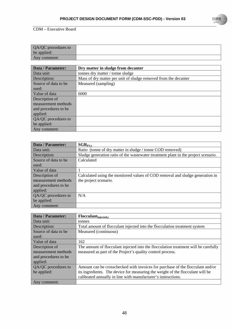
PROJECT DESIGN DOCUMENT FORM (CDM-SSC-PDD) - Version 03 CDM – Executive Board
48
QA/QC procedures to be applied:
Any comment:
Data / Parameter: Dry matter in sludge from decanter Data unit: tonnes dry matter / tonne sludge Description: Mass of dry matter per unit of sludge removed from the decanter Source of data to be used:
Measured (sampling)
Value of data 6000 Description of measurement methods and procedures to be applied:
QA/QC procedures to be applied:
Any comment:
Data / Parameter: SGRPJ,y
Data unit: Ratio (tonne of dry matter in sludge / tonne COD removed) Description: Sludge generation ratio of the wastewater treatment plant in the project scenario. Source of data to be used:
Calculated
Value of data 1 Description of measurement methods and procedures to be applied:
Calculated using the monitored values of COD removal and sludge generation in the project scenario.
QA/QC procedures to be applied:
N/A
Any comment:
Data / Parameter: Flocculantinjected,y
Data unit: tonnes Description: Total amount of flocculant injected into the flocculation treatment system Source of data to be used:
Measured (continuous)
Value of data 162 Description of measurement methods and procedures to be applied:
The amount of flocculant injected into the flocculation treatment will be carefully measured as part of the Project’s quality control process.
QA/QC procedures to be applied:
Amount can be crosschecked with invoices for purchase of the flocculant and/or its ingredients. The device for measuring the weight of the flocculant will be calibrated annually in line with manufacturer’s instructions.
Any comment:

PROJECT DESIGN DOCUMENT FORM (CDM-SSC-PDD) - Version 03 CDM – Executive Board
49
Data / Parameter: Qfloc,manuf,y Data unit: tonnes Description: Mass of the flocculant powder which is identified as being obtained from a
manufactured source. Source of data to be used:
Measured
Value of data 14.6 Description of measurement methods and procedures to be applied:
Each of the main ingredients in the flocculant powder is to be identified. Those ingredients which are identified as coming from a manufactured source will be included in the value for this parameter.
QA/QC procedures to be applied:
The value used can be crosschecked with purchase invoices or receipts.
Any comment: Used for leakage calculation
Data / Parameter: Flock,PJ,y Data unit: tonnes Description: Dry weight of the floc extracted from the flocculation treatment system Source of data to be used:
calculated
Value of data 1,310 t/yr Description of measurement methods and procedures to be applied:
Calculated as a factor of the total wet weight of floc extracted and the sample-based measurement of the amount of dry matter present in the floc.
QA/QC procedures to be applied:
N/A
Any comment:
Data / Parameter: Floc – wet weight Data unit: tonnes Description: Wet weight of the floc extracted from the flocculation treatment system Source of data to be used:
Measured (continuous)
Value of data 6,550 Description of measurement methods and procedures to be applied:
The weight of floc extracted from the flocculation treatment system will be measured continuously.
QA/QC procedures to be applied:
The weight measurement device used will be calibrated annually in line with manufacturer’s instructions.
Any comment:
Data / Parameter: Floc – dry matter portion Data unit: tonnes Description: Portion of dry matter in the floc extracted from the flocculation treatment system

PROJECT DESIGN DOCUMENT FORM (CDM-SSC-PDD) - Version 03 CDM – Executive Board
50
Source of data to be used:
Measured (sampling)
Value of data 20% Description of measurement methods and procedures to be applied:
Sampling will be carried out to determine the dry matter content.
QA/QC procedures to be applied:
Any comment:
Data / Parameter: Floc combusted Data unit: tonnes (dry weight) Description: Mass of solid material extracted from the flocculation treatment system and
combusted in the POM’s boiler Source of data to be used:
Measured (continuous)
Value of data 1310 t/yr Description of measurement methods and procedures to be applied:
The system for injecting the dried floc into the boiler will be equipped with a weight measurement device.
QA/QC procedures to be applied:
The weight measurement device will be calibrated annually in line with manufacturer’s instructions.
Any comment: This measurement is required to demonstrate that floc is being disposed of by combustion
Data / Parameter: Qww,in,y Data unit: m3
Description: Quantity of wastewater entering the Project’s wastewater treatment system Source of data to be used:
Measured (continuous)
Value of data 145,302 Description of measurement methods and procedures to be applied:
The flow of wastewater from the POM into the Project will be monitored continuously with an online flow metre.
QA/QC procedures to be applied:
The flow metre will be calibrated annually in line with manufacturer’s instructions.
Any comment:
Data / Parameter: Qww,discharge,y
Data unit: m3 Description: Quantity of wastewater discharged from the Project’s wastewater treatment
system Source of data to be Measured (continuous)
PROJECT DESIGN DOCUMENT FORM (CDM-SSC-PDD) - Version 03 CDM – Executive Board
51
used: Value of data 145,302 Description of measurement methods and procedures to be applied:
The flow of wastewater at the exit point from the Project will be monitored continuously with an online flow metre.
QA/QC procedures to be applied:
The flow metre will be calibrated annually in line with manufacturer’s instructions.
Any comment:
Data / Parameter: Electricity consumed by Project Data unit: MWH Description: Electricity consumed by the Project Source of data to be used:
Measured (continuous)
Value of data Decanter: 85kW/h x 2 decanters x 8760 hours per year = 1,489 MWh / year Flocculant treatment: 5 kW/h x 8760 hours per year = 43.8 MWh / year Sludge drying: 58.4 kW/h x 8760 hours per year = 512 MWh / year
Description of measurement methods and procedures to be applied:
Electricity consumption will be monitored by an online electricity metre.
QA/QC procedures to be applied:
The electricity meter will be calibrated once per year in line with manufacturer’s instructions.
Any comment: The project will obtain all of its electricity from the biomass cogeneration equipment at the POM, therefore the electricity consumption does not lead to any project emissions of greenhouse gases. However, this item is included in the monitoring plan for transparency.
Data / Parameter: Fossil fuel consumed by Project Data unit: Tonnes Description: Fossil fuel consumed by the Project Source of data to be used:
Monitored at point of use
Value of data 0 Description of measurement methods and procedures to be applied:
QA/QC procedures to be applied:
Monitored quantities can be cross-checked against invoices or purchase receipts of fossil fuel
Any comment: The project will obtain all of its heat requirements from the biomass cogeneration equipment at the POM, therefore no fossil fuel will be consumed. However, this item is included in the monitoring plan for transparency.
PROJECT DESIGN DOCUMENT FORM (CDM-SSC-PDD) - Version 03 CDM – Executive Board
52
B.7.2 Description of the monitoring plan: TEE, the senior partner in the project, has achieved both ISO9001 and ISO14001 certification. As part of the commercial arrangement between TEE and the Mill, day to day operational functions, including monitoring of the Project’s performance will be carried out by the Mill’s staff, with appropriate guidance and training to be provided by TEE. Periodic monitoring items, such as sampling of COD levels, or calibration of key instruments, will be carried out either directly by TEE, or by contracting to a third party specialist. Further, TEE will carry out a secondary quality check on all monitored data, with regular updates of the data being supplied to TEE. API will form an operational and management team, which will be responsible for carrying out all monitoring functions as prescribed in the Monitoring Plan. This team composes of a general manager, supervisor and operators. The operators, who are under the supervisor, will be assigned for monitoring of the parameters on a timely basis as well as recording and archiving data in an orderly manner. Monitoring reports will be forwarded to and reviewed by the general manager on a weekly basis in order to ensure the Project follows the requirements of the monitoring plan. Data monitored and required for verification and issuance will be kept for a minimum of two (2) years after the end of the crediting period or the last issuance of CERs for this project activity, whichever occurs later. Data archived will also be verified regularly by the DOE. The performance of the Project will be reviewed and analyzed by the CDM consultant on a regular basis. The figure below outlines the management and operational structure that API will implement to monitor emission reductions and any leakage effects generated by the Project.
Figure B.7.I – Management and operational structure for monitoring

PROJECT DESIGN DOCUMENT FORM (CDM-SSC-PDD) - Version 03 CDM – Executive Board
53
B.8 Date of completion of the application of the baseline and monitoring methodology and the name of the responsible person(s)/entity(ies) Date of completing the final draft of this baseline section (DD/MM/YYYY): 15/01/2009 Name of person/entity determining the baseline: Tokyo Electric Power Environmental Engineering Co., Inc 4-6-14 Shibaura, Minato-ku, Tokyo. 108-8537 Tel: +81-3-6372-7125 Fax: +81-3-6372-7164 Email: [email protected] Clean Energy Finance Committee, Mitsubishi UFJ Securities Co., Ltd. KR Toyosu Building, 2F, Toyosu 5-4-9, Koto-ku, Tokyo. Tel: +81-3-6213-2859 Fax: +81-3-6213-6175
PROJECT DESIGN DOCUMENT FORM (CDM-SSC-PDD) - Version 03 CDM – Executive Board
54
Email: [email protected] SECTION C. Duration of the project activity / crediting period C.1 Duration of the project activity: C.1.1. Starting date of the project activity: 01/04/2010 This is the date on which the Project Participants expect to make the final decision regarding allocation of capital to this project. C.1.2. Expected operational lifetime of the project activity: 20 years, based on the operational lifetime of the key equipment to be used in the Project. C.2 Choice of the crediting period and related information: C.2.1. Renewable crediting period C.2.1.1. Starting date of the first crediting period: N/A C.2.1.2. Length of the first crediting period: N/A C.2.2. Fixed crediting period: C.2.2.1. Starting date: 01/10/2011 C.2.2.2. Length: 10 years SECTION D. Environmental impacts >> D.1. If required by the host Party, documentation on the analysis of the environmental impacts of the project activity: According to the applicable legislation (Malaysian Environmental Quality Order 1987), new developments which contribute to the improvement of quality of a wastewater source do not have to carry out a full Environmental Impact Assessment.
PROJECT DESIGN DOCUMENT FORM (CDM-SSC-PDD) - Version 03 CDM – Executive Board
55
D.2. If environmental impacts are considered significant by the project participants or the host Party, please provide conclusions and all references to support documentation of an environmental impact assessment undertaken in accordance with the procedures as required by the host Party: Negative environmental impacts are not thought to be significant. The project will use energy from the POM’s existing biomass boilers, and will simply be cleaning up the wastewater treatment process. SECTION E. Stakeholders’ comments E.1. Brief description how comments by local stakeholders have been invited and compiled: TBA: The formal CDM stakeholder meeting will be conducted following approval of a new small scale methodology submitted for the Project. E.2. Summary of the comments received: E.3. Report on how due account was taken of any comments received:

PROJECT DESIGN DOCUMENT FORM (CDM-SSC-PDD) - Version 03 CDM – Executive Board
56
Annex 1
CONTACT INFORMATION ON PARTICIPANTS IN THE PROJECT ACTIVITY Organization: Tokyo Electric Power Environmental Engineering Co., Inc Street/P.O.Box: 4-6-14 Shibaura Building: City: Minato-ku State/Region: Tokyo Postfix/ZIP: 108-8537 Country: Telephone: +81-3-6372-7125 FAX: +81-3-6372-7164 E-Mail: [email protected] URL: http://www.tee-kk.co.jp Represented by: Title: Director Salutation: Mr Last Name: Yamamoto Middle Name: First Name: Yoshiyuki Department: Environment Business Mobile: Direct FAX: Direct tel: Personal E-Mail: Organization: KILANG KELAPA SAWIT BUKIT PASIR SDN.BHD. Street/P.O.Box: 103,843000 Building: City: Bukit Pasir,Muar,Johor State/Region: Postfix/ZIP: Country: Malaysia Telephone: +60-6-9856125 FAX: +60-6-9856428 E-Mail: [email protected] URL: Represented by: Title: Mill Manager/Engineer Salutation: Mr Last Name: LEE Middle Name: First Name: Mang Cheang Department: Mobile:

PROJECT DESIGN DOCUMENT FORM (CDM-SSC-PDD) - Version 03 CDM – Executive Board
57
Direct FAX: Direct tel: Personal E-Mail:

PROJECT DESIGN DOCUMENT FORM (CDM-SSC-PDD) - Version 03 CDM – Executive Board
58
Annex 2
INFORMATION REGARDING PUBLIC FUNDING The project received funding from the Global Environmental Centre, a Japanese government agency, for the initial Feasibility Study.
PROJECT DESIGN DOCUMENT FORM (CDM-SSC-PDD) - Version 03 CDM – Executive Board
59
Annex 3
BASELINE INFORMATION
All calculations and parameters for the baseline calculation are included in full in section B.7 above. A spreadsheet with the emission reduction calculation is also attached.
Annex 4
MONITORING INFORMATION All information related to the monitoring is outlined in section B.7 above.
- - - - -