clearfire condensing boiler -...
TRANSCRIPT

CFC-EClearFire Condensing Boiler
Boiler Book05/2019

BOILER BOOK CFC-E
2
Table of ContentsFEATURES AND BENEFITS . . . . . . . . . . . . . . . . . . . . . . . . . . . . . . . . . . . . . . . . . . . . . . . . . . . . . . . . . . . . . . . . . . . . 4PRODUCT OFFERING . . . . . . . . . . . . . . . . . . . . . . . . . . . . . . . . . . . . . . . . . . . . . . . . . . . . . . . . . . . . . . . . . . . . . . . . 6DIMENSIONS AND RATINGS . . . . . . . . . . . . . . . . . . . . . . . . . . . . . . . . . . . . . . . . . . . . . . . . . . . . . . . . . . . . . . . . . . . 8PERFORMANCE DATA . . . . . . . . . . . . . . . . . . . . . . . . . . . . . . . . . . . . . . . . . . . . . . . . . . . . . . . . . . . . . . . . . . . . . . . 13ENGINEERING DATA . . . . . . . . . . . . . . . . . . . . . . . . . . . . . . . . . . . . . . . . . . . . . . . . . . . . . . . . . . . . . . . . . . . . . . . . 20STACK/BREECHING SIZE CRITERIA . . . . . . . . . . . . . . . . . . . . . . . . . . . . . . . . . . . . . . . . . . . . . . . . . . . . . . . . . . . . . 44CB FALCON CONTROLLER . . . . . . . . . . . . . . . . . . . . . . . . . . . . . . . . . . . . . . . . . . . . . . . . . . . . . . . . . . . . . . . . . . . . 53EXAMPLE SYSTEM SCHEMATICS . . . . . . . . . . . . . . . . . . . . . . . . . . . . . . . . . . . . . . . . . . . . . . . . . . . . . . . . . . . . . . . 56
List of FiguresFireside Access . . . . . . . . . . . . . . . . . . . . . . . . . . . . . . . . . . . . . . . . . . . . . . . . . . . . . . . . . . . . . . . . . . . . . . . . . . . . . 4Premix Burner Technology . . . . . . . . . . . . . . . . . . . . . . . . . . . . . . . . . . . . . . . . . . . . . . . . . . . . . . . . . . . . . . . . . . . . . 5ClearFire CE Control Panel . . . . . . . . . . . . . . . . . . . . . . . . . . . . . . . . . . . . . . . . . . . . . . . . . . . . . . . . . . . . . . . . . . . . . 7Model CFC-E Dimensional Views . . . . . . . . . . . . . . . . . . . . . . . . . . . . . . . . . . . . . . . . . . . . . . . . . . . . . . . . . . . . . . . . . 9Efficiencies . . . . . . . . . . . . . . . . . . . . . . . . . . . . . . . . . . . . . . . . . . . . . . . . . . . . . . . . . . . . . . . . . . . . . . . . . . . . 15-19Waterside Pressure Drop . . . . . . . . . . . . . . . . . . . . . . . . . . . . . . . . . . . . . . . . . . . . . . . . . . . . . . . . . . . . . . . . . . 21-25High Fire Speed Settings vs. % Glycol . . . . . . . . . . . . . . . . . . . . . . . . . . . . . . . . . . . . . . . . . . . . . . . . . . . . . . . . . . . . 30Maximum Firing Rate vs. % Glycol . . . . . . . . . . . . . . . . . . . . . . . . . . . . . . . . . . . . . . . . . . . . . . . . . . . . . . . . . . . . . . . 30Condensate Piped Direct to Drain . . . . . . . . . . . . . . . . . . . . . . . . . . . . . . . . . . . . . . . . . . . . . . . . . . . . . . . . . . . . . . . 31Neutralization Capsule . . . . . . . . . . . . . . . . . . . . . . . . . . . . . . . . . . . . . . . . . . . . . . . . . . . . . . . . . . . . . . . . . . . . . . . 31Combo Trap/Tank . . . . . . . . . . . . . . . . . . . . . . . . . . . . . . . . . . . . . . . . . . . . . . . . . . . . . . . . . . . . . . . . . . . . . . . . . . 32Treatment Tank . . . . . . . . . . . . . . . . . . . . . . . . . . . . . . . . . . . . . . . . . . . . . . . . . . . . . . . . . . . . . . . . . . . . . . . . . . . . 33Condensate Piping for Multiple Boilers . . . . . . . . . . . . . . . . . . . . . . . . . . . . . . . . . . . . . . . . . . . . . . . . . . . . . . . . . . . . 34Tank Detail, Multiple Boilers . . . . . . . . . . . . . . . . . . . . . . . . . . . . . . . . . . . . . . . . . . . . . . . . . . . . . . . . . . . . . . . . . . . 34Gas Piping Schematic . . . . . . . . . . . . . . . . . . . . . . . . . . . . . . . . . . . . . . . . . . . . . . . . . . . . . . . . . . . . . . . . . . . . . . . . 35Gas Header Piping . . . . . . . . . . . . . . . . . . . . . . . . . . . . . . . . . . . . . . . . . . . . . . . . . . . . . . . . . . . . . . . . . . . . . . . . . . 36Model CFC-E Minimum Room Clearance Dimensions . . . . . . . . . . . . . . . . . . . . . . . . . . . . . . . . . . . . . . . . . . . . . . . . . . 38CFC-E Seismic Mounting . . . . . . . . . . . . . . . . . . . . . . . . . . . . . . . . . . . . . . . . . . . . . . . . . . . . . . . . . . . . . . . . . . . . . 38Two Opening Outside Wall Method . . . . . . . . . . . . . . . . . . . . . . . . . . . . . . . . . . . . . . . . . . . . . . . . . . . . . . . . . . . . . . 40Two Opening Ducted Method . . . . . . . . . . . . . . . . . . . . . . . . . . . . . . . . . . . . . . . . . . . . . . . . . . . . . . . . . . . . . . . . . . 41One Opening Method . . . . . . . . . . . . . . . . . . . . . . . . . . . . . . . . . . . . . . . . . . . . . . . . . . . . . . . . . . . . . . . . . . . . . . . . 42Two Opening Engineered Method . . . . . . . . . . . . . . . . . . . . . . . . . . . . . . . . . . . . . . . . . . . . . . . . . . . . . . . . . . . . . . . . 43Boiler Air Inlet . . . . . . . . . . . . . . . . . . . . . . . . . . . . . . . . . . . . . . . . . . . . . . . . . . . . . . . . . . . . . . . . . . . . . . . . . . . . . 44Horizontal through-wall venting using inside air for combustion . . . . . . . . . . . . . . . . . . . . . . . . . . . . . . . . . . . . . . . . . . . 47Horizontal flue through-wall with direct vent combustion intake . . . . . . . . . . . . . . . . . . . . . . . . . . . . . . . . . . . . . . . . . . . 48Inside Air - Vertical Vent . . . . . . . . . . . . . . . . . . . . . . . . . . . . . . . . . . . . . . . . . . . . . . . . . . . . . . . . . . . . . . . . . . . . . . 50Vertical Stack with Direct Vent Combustion Air . . . . . . . . . . . . . . . . . . . . . . . . . . . . . . . . . . . . . . . . . . . . . . . . . . . . . . 51CFC-E Rear Connections . . . . . . . . . . . . . . . . . . . . . . . . . . . . . . . . . . . . . . . . . . . . . . . . . . . . . . . . . . . . . . . . . . . . . . 52CB Falcon Pinout . . . . . . . . . . . . . . . . . . . . . . . . . . . . . . . . . . . . . . . . . . . . . . . . . . . . . . . . . . . . . . . . . . . . . . . . . . . 55Primary/Secondary Piping Schematic, Single Boiler . . . . . . . . . . . . . . . . . . . . . . . . . . . . . . . . . . . . . . . . . . . . . . . . . . . 57Primary/Secondary Piping Schematic, Two Boilers . . . . . . . . . . . . . . . . . . . . . . . . . . . . . . . . . . . . . . . . . . . . . . . . . . . . 58Primary/Secondary Piping Schematic, Three Boilers . . . . . . . . . . . . . . . . . . . . . . . . . . . . . . . . . . . . . . . . . . . . . . . . . . . 59Primary Variable Flow Piping Schematic, Single Boiler . . . . . . . . . . . . . . . . . . . . . . . . . . . . . . . . . . . . . . . . . . . . . . . . . 60Primary Variable Flow Piping Schematic, Two Boilers . . . . . . . . . . . . . . . . . . . . . . . . . . . . . . . . . . . . . . . . . . . . . . . . . 61Primary Variable Flow Piping Schematic, Three Boilers . . . . . . . . . . . . . . . . . . . . . . . . . . . . . . . . . . . . . . . . . . . . . . . . 62Primary Variable Flow Piping Schematic, Single Boiler with Heat Exchanger . . . . . . . . . . . . . . . . . . . . . . . . . . . . . . . . . . 63Primary Variable Flow Piping Schematic, Single Boiler with Heat Exchanger and Dual Return . . . . . . . . . . . . . . . . . . . . . . 64
List of Tables
U.S. Standard Dimensions Model CFC-E Boiler . . . . . . . . . . . . . . . . . . . . . . . . . . . . . . . . . . . . . . . . . . . . . . . . . . . . . . 10Dimensions (Metric) Model CFC-E . . . . . . . . . . . . . . . . . . . . . . . . . . . . . . . . . . . . . . . . . . . . . . . . . . . . . . . . . . . . . . . 11Model CFC-E Boiler Ratings (Sea Level to 2000 Feet) . . . . . . . . . . . . . . . . . . . . . . . . . . . . . . . . . . . . . . . . . . . . . . . . . 12Altitude Correction for Input Capacity at Various Altitude Levels . . . . . . . . . . . . . . . . . . . . . . . . . . . . . . . . . . . . . . . . . . 13CFC-E Efficiencies . . . . . . . . . . . . . . . . . . . . . . . . . . . . . . . . . . . . . . . . . . . . . . . . . . . . . . . . . . . . . . . . . . . . . . . . . . 14Emissions . . . . . . . . . . . . . . . . . . . . . . . . . . . . . . . . . . . . . . . . . . . . . . . . . . . . . . . . . . . . . . . . . . . . . . . . . . . . . . . . 19Noise level (dBA) measured 3 feet in front of boiler . . . . . . . . . . . . . . . . . . . . . . . . . . . . . . . . . . . . . . . . . . . . . . . . . . . 20Flow Rates . . . . . . . . . . . . . . . . . . . . . . . . . . . . . . . . . . . . . . . . . . . . . . . . . . . . . . . . . . . . . . . . . . . . . . . . . . . . . . . 21

BOILER BOOK CFC-E
3
Model CFC-E Minimum Over Pressure Requirements . . . . . . . . . . . . . . . . . . . . . . . . . . . . . . . . . . . . . . . . . . . . . . . . . . 26Safety Relief Valve Information . . . . . . . . . . . . . . . . . . . . . . . . . . . . . . . . . . . . . . . . . . . . . . . . . . . . . . . . . . . . . . . . . 27Model CFC-E Water Chemistry Requirements in accordance with ABMA . . . . . . . . . . . . . . . . . . . . . . . . . . . . . . . . . . . . 28Glycol Minimum Flow Recommendations for ClearFire Model CFC-E Boiler . . . . . . . . . . . . . . . . . . . . . . . . . . . . . . . . . . . 29Condensate piping for multiple boilers . . . . . . . . . . . . . . . . . . . . . . . . . . . . . . . . . . . . . . . . . . . . . . . . . . . . . . . . . . . . 33Model CFC-E Minimum and Maximum Gas Pressure . . . . . . . . . . . . . . . . . . . . . . . . . . . . . . . . . . . . . . . . . . . . . . . . . . 36Model CFC-E Minimum Required Gas Pressure Altitude Correction . . . . . . . . . . . . . . . . . . . . . . . . . . . . . . . . . . . . . . . . 37Stack Sizing Using Outside Air for Combustion . . . . . . . . . . . . . . . . . . . . . . . . . . . . . . . . . . . . . . . . . . . . . . . . . . . . . . 49Operating Conditions - Controller . . . . . . . . . . . . . . . . . . . . . . . . . . . . . . . . . . . . . . . . . . . . . . . . . . . . . . . . . . . . . . . . 53Operating Conditions - Display/Interface . . . . . . . . . . . . . . . . . . . . . . . . . . . . . . . . . . . . . . . . . . . . . . . . . . . . . . . . . . . 53CB Falcon burner sequence (Central Heat) . . . . . . . . . . . . . . . . . . . . . . . . . . . . . . . . . . . . . . . . . . . . . . . . . . . . . . . . . 54

BOILER BOOK CFC-E FEATURES AND BENEFITS
4
FEATURES AND BENEFITSCompact Firetube DesignThe Model CFC-E boiler is a high mass, vertical down fired robust firetube boiler. The internalextended-heating surface tubes provide very high levels of performance in a compact space.
Large Water Volume
The large water volume makes the CFC-E ideal for variable flow primary pumping systems.
Advanced TechnologyTubes, tube sheets, and combustion chamber are constructed from UNS S32101 duplex stainlesssteel. Tubes feature AluFer tube technology for optimal heat transfer.
Advanced Fireside ConstructionThe extended heating surface design provides the ideal solution for the demands of a condensingboiler and helps to recover virtually all the latent heat of the flue gas. Each tube consists of an outerstainless steel tube (waterside) and the AluFer extended heating surface profile on the flue gas side.
High EfficiencyWith the extended heating surface tubes the CFC-E boiler will provide fuel to water efficiency of up to99% at low fire and 95% at high fire with 80 degrees F return water temperature.
Ease of MaintenanceThe powder coated steel casing is designed for easy removal and re-assembly. As shown in Figure 1,the burner is hinged and is provided with hydraulic pistons for simple opening for service of the sparkelectrode, inspection of the burner cylinder, tubes and combustion chamber.
Figure 1. Fireside Access
Quality ConstructionASME Code construction ensures high quality design, safety, third party inspection, and reliability,and accordingly bears the ASME Section IV “H” stamp.
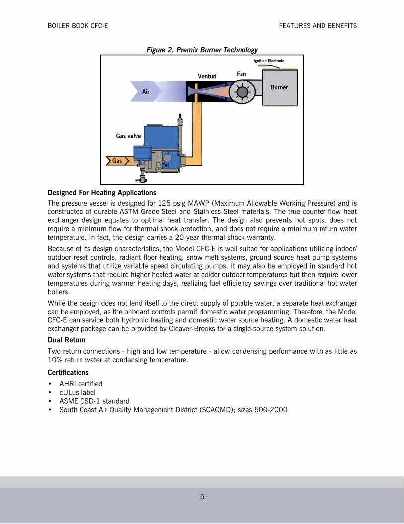
Premix TechnologyThe burner utilizes “Premix” technology to mix both gas fuel and combustion air prior to entering theburner canister, with air leading the fuel during burner firing transitions. Combined with the surfacecombustion burner and self-regulating gas valve-venturi fuel-air ratio control, this technology providesvery low emission levels, exceptionally safe operation, and nearly 100% combustion efficiency.
Full ModulationThe variable speed combustion air blower with ECM technology provides modulated firing for preciselinear load tracking, reduced on-off cycling, and reduced electrical consumption.
BOILER BOOK CFC-E FEATURES AND BENEFITS
5
Figure 2. Premix Burner Technology
Designed For Heating ApplicationsThe pressure vessel is designed for 125 psig MAWP (Maximum Allowable Working Pressure) and isconstructed of durable ASTM Grade Steel and Stainless Steel materials. The true counter flow heatexchanger design equates to optimal heat transfer. The design also prevents hot spots, does notrequire a minimum flow for thermal shock protection, and does not require a minimum return watertemperature. In fact, the design carries a 20-year thermal shock warranty.
Because of its design characteristics, the Model CFC-E is well suited for applications utilizing indoor/outdoor reset controls, radiant floor heating, snow melt systems, ground source heat pump systemsand systems that utilize variable speed circulating pumps. It may also be employed in standard hotwater systems that require higher heated water at colder outdoor temperatures but then require lowertemperatures during warmer heating days, realizing fuel efficiency savings over traditional hot waterboilers.
While the design does not lend itself to the direct supply of potable water, a separate heat exchangercan be employed, as the onboard controls permit domestic water programming. Therefore, the ModelCFC-E can service both hydronic heating and domestic water source heating. A domestic water heatexchanger package can be provided by Cleaver-Brooks for a single-source system solution.
Dual Return
Two return connections - high and low temperature - allow condensing performance with as little as10% return water at condensing temperature.
Certifications
• AHRI certified• cULus label• ASME CSD-1 standard• South Coast Air Quality Management District (SCAQMD); sizes 500-2000
BOILER BOOK CFC-E PRODUCT OFFERING
6
PRODUCT OFFERINGDimensions, ratings, and product information may change to meet current market requirements andproduct improvements. Therefore, use this information as a guide.
Standard Equipment
Equipment described below is for the standard boiler offering:
1. The BoilerA. Each boiler size is designed for a Maximum Allowable Working Pressure (MAWP) of 125 psig
(8.6 Bar), constructed in accordance with the ASME Code Section IV and bear the “H” stamp.B. The insulated pressure vessel is mounted on a base and a powder coated steel casing is
provided.C. A drain valve connection is provided at the front bottom for field piping of a boiler drain valve,
which can be furnished as an option.2. Boiler Trim and Controls
• The following items are furnished:
• Probe Type Low Water Cutoff control, manual reset.
• High Water Temperature Cutoff, manual reset.
• NTC (negative temp. coefficient) sensor for hot water supply temperature.
• NTC sensor for hot water return temperature.
• ASME Safety Relief Valve set @ 125 psig. (8.6 Bar) (Optional SRV set points available.)
• Combination Temperature/Pressure Gauge.
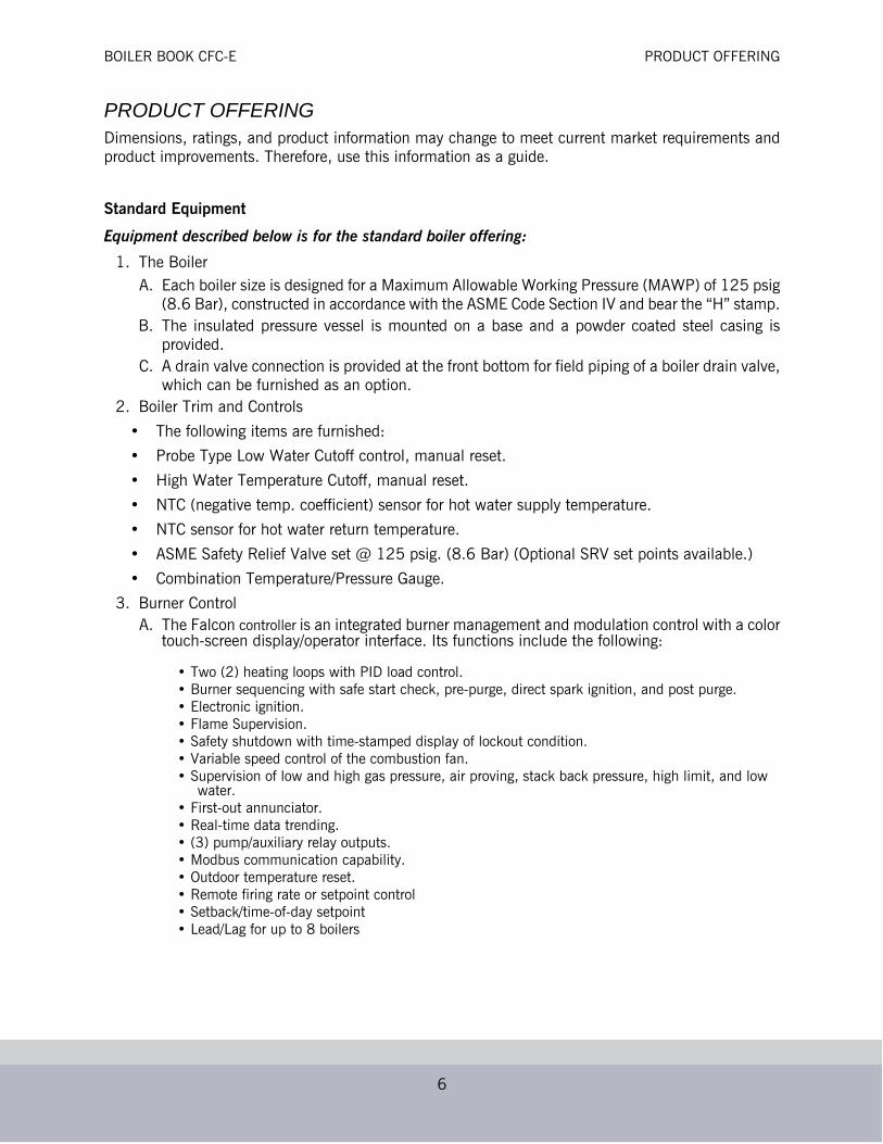
3. Burner ControlA. The Falcon controller is an integrated burner management and modulation control with a color
touch-screen display/operator interface. Its functions include the following:
• Two (2) heating loops with PID load control.• Burner sequencing with safe start check, pre-purge, direct spark ignition, and post purge.• Electronic ignition.• Flame Supervision.• Safety shutdown with time-stamped display of lockout condition.• Variable speed control of the combustion fan.• Supervision of low and high gas pressure, air proving, stack back pressure, high limit, and low
water.• First-out annunciator.• Real-time data trending.• (3) pump/auxiliary relay outputs.• Modbus communication capability.• Outdoor temperature reset.• Remote firing rate or setpoint control• Setback/time-of-day setpoint• Lead/Lag for up to 8 boilers

BOILER BOOK CFC-E PRODUCT OFFERING
7
Figure 3. CFC-E Control Panel (size 500-2000 shown)
4. Forced Draft BurnerA. The burner is a “Pre-mix” design consisting of a unitized venturi, single body dual safety gas
valve, blower, and burner head. Consistent fuel-air ratio is maintained with a self-regulatinggas valve-venturi system which automatically compensates for changes in air density.
B. Full modulation is accomplished with a variable speed fan.C. For near flameless combustion, the burner utilizes a Fecralloy-metal fiber head.D. Quiet operation - see Table 7 for details.E. Operating on Natural Gas, NOx emissions will be less than 20 PPM regardless of boiler size.F. As an option, the burner is capable of direct vent combustion.G. Ignition of the main flame is via direct spark (500-2000) or pilot ignition (3500-6000). A
UV scanner provides flame supervision.H. To ensure adequate combustion air is present prior to ignition, and to ensure the fan is
operating, a combustion air proving switch is furnished.I. A High Air Pressure Switch is provided to ensure burner lockout if excessive back pressure
due to a blocked stack occurs.J. For ease of maintenance and inspection, the burner is furnished with hydraulic rods and easy
opening lockdown nuts, which permit the burner to swing up. This provides full access to theburner and electrodes, as well, to the tube sheet and tubes.
K. High turndown burner 3500-6000 standard.
5. Burner Gas Train
The standard gas train is equipped in accordance with UL certification and complies with ASMECSD-1. Each burner gas train includes:
• Low Gas Pressure Interlock, manual reset.

BOILER BOOK CFC-E DIMENSIONS AND RATINGS
8
• High Gas Pressure Interlock, manual reset.
• ASME CSD-1 Test Cocks.
• Downstream manual ball type shutoff valve.
• Single body dual safety shutoff gas valve.
• Proof-of-closure valve (CFC-E 6000 only).
Optional EquipmentFor option details, contact the local authorized Cleaver-Brooks representative. In summary, here aresome of the options that can be provided with the boiler:
A. Reusable air filter.B. Condensate neutralization tank assembly - consists of neutralizing media, filter, and PVC condensate holding
tank with integral drain trap.C. Outside air intake for direct vent combustion.D. Outdoor temperature sensor for indoor/outdoor control.E. Header temperature sensor for multiple boiler Lead/Lag operation.F. Auxiliary Low Water Control (shipped loose) for field piping by others into the system piping.G. Alarm Horn and lights for safety shutdown.H. Relays for output signal for burner on, fuel valve open.I. Stack Thermometer.J. Stack temperature limit-sensor.K. Auto air vent.L. Boiler drain valve.M. Adjustable feet.N. Seismic anchoring brackets.O. Protocol translator for BMS communicationsP. Automatic boiler isolation valveQ. Remote monitoringR. Boiler stack systemsS. Draft dampers
DIMENSIONS AND RATINGSFor layout purposes, the overall dimensions for the Model CFC-E are shown in Table 1 (USDimensions) and Table 2 (Metric Dimensions) including the various pipe connection sizes for supplyand return water, drain, and vent. The performance ratings for the boiler are shown in Table 3.
Altitude See Table 4 for input capacity ratings at various altitude levels.

BOILER BOOK CFC-E DIMENSIONS AND RATINGS
9
Figure 4. Model CFC-E Dimensional Views
OPTIONAL ADJUSTABLE FEET ALLOW FOR1.56” TO 3.88” ADDITIONAL HEIGHT

BOILER BOOK CFC-E DIMENSIONS AND RATINGS
10
Table 1. U.S. Standard Dimensions Model CFC-E Boiler
ITEM DIMENSIONS (inches) 500 750 1000 1500 2000 3500 4000 5000 6000A Overall Height 78.0 78.0 78.0 79.9 79.9 91.2 91.2 93.6 93.6B Overall Width 34.9 34.9 34.9 35.8 35.8 48.4 48.4 58.7 58.7C Overall Depth 49.4 49.4 49.4 56 56 68.4 68.4 80.6 80.6D Width Less Casing 32.1 32.1 32.1 33.0 33.0 45.7 45.7 55.9 55.9E Gas Connection to Floor 70.3 70.3 70.3 73.9 73.9 77.7 77.7 79.5 79.5F Side of Casing to Gas Connection 3.7 3.7 3.7 7.1 7.1 4.9 4.9 4.6 4.6G Side of Casing to Air Inlet 10.8 10.8 10.8 10.8 10.8 11.0 11.0 12.0 12.0H Top of Casing to Air Inlet 7.7 7.7 7.7 7.1 7.1 9.0 9.0 9.9 9.9J Floor to Condensate Drain 6.3 6.3 6.3 6.3 6.3 5.7 5.7 5.7 5.7K Floor to Bottom of Casing 11.0 11.0 11.0 11.0 11.0 11.4 11.4 12.0 12.0L Side of Base to Flue Outlet (Centered) 7.4 7.4 7.4 8.5 8.5 8.8 8.8 10.0 10.0M Side of Base to Flue Outlet (Offset) 6.4 6.4 6.4 7.5 7.5 N/A N/A N/A N/AN Rear of Base to Flue Outlet 6.5 6.5 6.5 7.5 7.5 8.8 8.8 9.8 9.8P Casing Depth 36.3 36.3 36.3 42.4 42.4 52.5 52.5 62.1 62.1Q Casing Height 67.0 67.0 67.0 68.9 68.9 79.8 79.8 81.6 81.6R Floor to Lower Return Connection 16.8 16.8 16.8 16.8 16.8 16.8 16.8 18.5 18.5S Floor to Upper Return Connection 31.8 31.8 31.8 31.8 31.8 32.6 32.6 32.3 32.3T Floor to Supply Connection 59.5 59.5 59.5 59.5 59.5 62.3 62.3 63.3 63.3U Floor to Air vent Connection 66.3 66.3 66.3 66.3 66.3 70.3 70.3 71.9 71.9V Air Vent Line Projection from Rear of Casing 3.2 3.2 3.2 3.3 3.3 2.2 2.2 2.8 2.8
CONNECTIONSW Water Low Temp. Return, Class150 RF Flange 2-1/2” 2-1/2” 2-1/2” 4” 4” 5” 5” 6” 6”X Water High Temp. Return, Class150 RF Flange 2-1/2” 2-1/2” 2-1/2” 4” 4” 5” 5” 6” 6”Y Water Outlet, Class150 RF Flange 2-1/2” 2-1/2” 2-1/2” 4” 4” 5” 5” 6” 6”Z Air Vent, NPT 1-1/2” 1-1/2” 1-1/2” 1-1/2” 1-1/2” 1-1/2” 1-1/2” 1-1/2” 1-1/2”
AA Vessel Drain, NPT 1-1/2” 1-1/2” 1-1/2” 1-1/2” 1-1/2” 1-1/2” 1-1/2” 1-1/2” 1-1/2”BB Flue Gas Outlet
(Standard) - Nominal 6” 6” 8” 8” 8” 12” 12” 14” 14”(Option) - Nominal 8” 8” 6” 10” 10” NA NA 16” 16”
CC Combustion Air - Nominal 6” 6” 6" 8" 8" 12" 12" 14" 14"DD Gas, NPT 1" 1" 1" 1-1/2” 1-1/2” 2 2 2" 2"EE Condensate Drain, NPT 1" 1" 1" 1" 1" 1" 1" 1" 1"FF Electrical Opening, Left or Right 1.6" 1.6" 1.6" 1.6" 1.6" 1.6" 1.6" 1.6" 1.6"GG Safety Relief Valve Vessel Connection, NPT 1-1/4” 1-1/4” 1-1/4” 1-1/4” 1-1/4” 2" 2" 2" 2"HH Safety Relief Valve SEE TABLE 10JJ Flue Coupling, NPT 3/4” 3/4” 3/4” 3/4” 3/4” 3/4” 3/4” 3/4” 3/4”KK Water Outlet Coupling, NPT 1/2” 1/2” 1/2” 1/2” 1/2” 1/2” 1/2” 1/2” 1/2”
FORK POCKETS (inches)LL Pocket Height 3.9 3.9 3.9 3.9 3.9 3.9 3.9 3.9 3.9
MM Pocket Width 11.8 11.8 11.8 11.8 11.8 11.8 11.8 11.8 11.8NN Overall Pocket Width 27.6 27.6 27.6 27.6 27.6 27.6 27.6 27.6 27.6
WEIGHTSDry Weight (lb) 1298 1298 1396 1861 2041 3575 3760 4900 5225Shipping Weight (lb) 1413 1413 1511 1986 2166 3725 3915 5075 5450Operating Weight (lb) 2065 2065 2113 2778 2858 5230 5305 7505 7660Water Volume (gallon) 92 92 86 110 98 198 185 312 285
CLEARANCESTop 14" Notes:
•Boiler rear must be accessible for servicing.•Side clearance to wall or between boilers.•Side clearance typical each side.•Local code requirements, if more stringent, should take precedence.
Side 3"Rear 20"Front 36"
BOILER BOOK CFC-E DIMENSIONS AND RATINGS
11
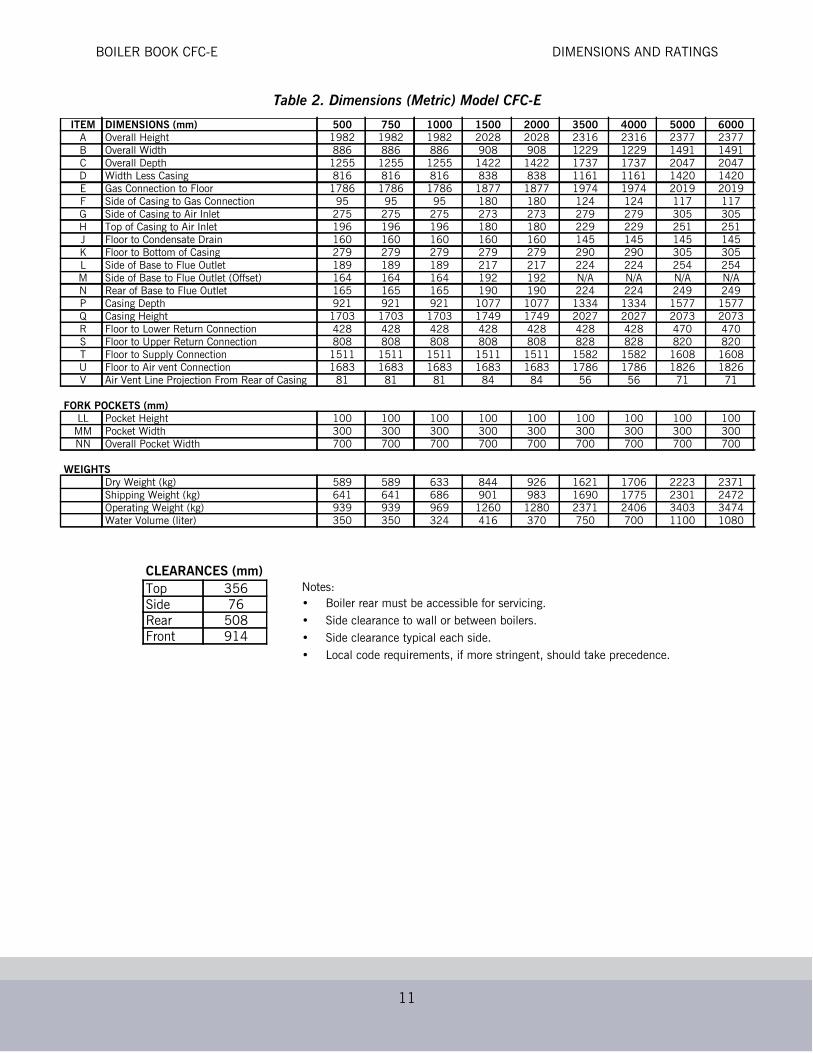
Table 2. Dimensions (Metric) Model CFC-E
ITEM DIMENSIONS (mm) 500 750 1000 1500 2000 3500 4000 5000 6000A Overall Height 1982 1982 1982 2028 2028 2316 2316 2377 2377B Overall Width 886 886 886 908 908 1229 1229 1491 1491C Overall Depth 1255 1255 1255 1422 1422 1737 1737 2047 2047D Width Less Casing 816 816 816 838 838 1161 1161 1420 1420E Gas Connection to Floor 1786 1786 1786 1877 1877 1974 1974 2019 2019F Side of Casing to Gas Connection 95 95 95 180 180 124 124 117 117G Side of Casing to Air Inlet 275 275 275 273 273 279 279 305 305H Top of Casing to Air Inlet 196 196 196 180 180 229 229 251 251J Floor to Condensate Drain 160 160 160 160 160 145 145 145 145K Floor to Bottom of Casing 279 279 279 279 279 290 290 305 305L Side of Base to Flue Outlet 189 189 189 217 217 224 224 254 254M Side of Base to Flue Outlet (Offset) 164 164 164 192 192 N/A N/A N/A N/AN Rear of Base to Flue Outlet 165 165 165 190 190 224 224 249 249P Casing Depth 921 921 921 1077 1077 1334 1334 1577 1577Q Casing Height 1703 1703 1703 1749 1749 2027 2027 2073 2073R Floor to Lower Return Connection 428 428 428 428 428 428 428 470 470S Floor to Upper Return Connection 808 808 808 808 808 828 828 820 820T Floor to Supply Connection 1511 1511 1511 1511 1511 1582 1582 1608 1608U Floor to Air vent Connection 1683 1683 1683 1683 1683 1786 1786 1826 1826V Air Vent Line Projection From Rear of Casing 81 81 81 84 84 56 56 71 71
FORK POCKETS (mm)LL Pocket Height 100 100 100 100 100 100 100 100 100
MM Pocket Width 300 300 300 300 300 300 300 300 300NN Overall Pocket Width 700 700 700 700 700 700 700 700 700
WEIGHTSDry Weight (kg) 589 589 633 844 926 1621 1706 2223 2371Shipping Weight (kg) 641 641 686 901 983 1690 1775 2301 2472Operating Weight (kg) 939 939 969 1260 1280 2371 2406 3403 3474Water Volume (liter) 350 350 324 416 370 750 700 1100 1080
CLEARANCES (mm)Notes:• Boiler rear must be accessible for servicing.• Side clearance to wall or between boilers.• Side clearance typical each side.• Local code requirements, if more stringent, should take precedence.
Top 356Side 76Rear 508Front 914

BOILER BOOK CFC-E DIMENSIONS AND RATINGS
12
Table 3. Model CFC-E Boiler Ratings (Sea Level to 2000 Feet)
*CFC-E 4000: 8% derate with 9 ppm NOx. If full capacity is required, contact your local Cleaver-Brooks representative for additionalinformation.
Boiler SizeDescription Units 500 750 1000 1500 2000 3500 4000 5000 6000
Input Max. Btu/Hr 500,000 750,000 1,000,000 1,500,000 2,000,000 3,500,000 4,000,000 5,000,000 6,000,000 KCal/Hr 126,000 189,000 252,000 378,000 504,000 882,000 1,008,000 1,260,000 1,512,000
Natural Gas Ft3/Hr 500 750 1000 1500 2000 3500 4000 5000 6000
Propane Ft3/Hr 200 300 400 600 800 1400 1600 2000 2400
Natural Gas M3/Hr 14 21 28 42 57 99 113 142 170
Propane M3/Hr 5.7 8.5 11 17 23 40 45 57 68
Output at 120/80 F [49/27 C] 100% Firing
Btu/Hr 470,000 705,000 940,000 1,410,000 1,880,000 3,290,000 3,760,000* 4,700,000 5,640,000KCal/Hr 118,440 177,660 236,880 355,320 473,760 829,080 947,520* 1,184,400 1,421,280
BHP 14 21 28 42 56 98 112* 140 168KW 138 207 275 413 551 964 1102* 1377 1653
Output at 180/140 F [82/60 C] 100% Firing
Btu/Hr 440,000 660,000 880,000 1,320,000 1,760,000 3,080,000 3,520,000* 4,400,000 5,280,000KCal/Hr 110,880 166,320 221,760 332,640 443,520 776,160 887,040* 1,108,800 1,330,560
BHP 13 20 26 39 53 92 105* 131 158KW 129 193 258 387 516 903 1032* 1290 1547
MAWP psi 125 125 125 125 125 125 125 125 125Bar 8.6 8.6 8.6 8.6 8.6 8.6 8.6 8.6 8.6
MAWT °F 210 210 210 210 210 210 210 210 210°C 99 99 99 99 99 99 99 99 99
Water Content Gallons 92 92 86 110 98 198 185 312 285Liters 350 350 324 416 370 750 700 1180 1080
Weight w/o Water Pounds 1,298 1,298 1,396 1,861 2,041 3574 3761 4901 5278Kg 589 589 633 844 926 1621 1706 2223 2394
Standby Heat Loss Btu/Hr 1000 1500 2000 3000 4000 7000 8000 10000 12000Watts 293 440 586 879 1172 2051 2344 2930 3516
ECM Blower Motor Size Watts 345 345 345 1,700 1,700 2,400 2,400 8,000 8,000Operating Voltage, Blower Volts/Ph/Hz 115/1/60 115/1/60 115/1/60 115/1/60 115/1/60 460/3/60 460/3/60 460/3/60 460/3/60Control Circuit Volts/Ph/Hz 115/1/60 115/1/60 115/1/60 115/1/60 115/1/60 115/1/60 115/1/60 115/1/60 115/1/60Max Current Draw, Blower Amperes 4 4 4 13.5 13.5 4 4 12.7 12.7Max Current Draw Control Circuit
Amperes 1.5 1.5 1.5 2 2 2 2 2 2
Max Over Current Protection Amperes 20 20 20 20 20 20 20 20 20
Condensate Qty Firing Nat. Gas & operating @ 120/80 F.
Gal/Hr 3.5 5 6.5 10 13.5 24.0 27.0 34.0 40.5
Flue Gas Mass Flow @ 100% Firing
lb/hr 557 835 1,113 1,670 2,226 3,897 4,452 5,567 6,678kg/hr 252 379 505 758 1010 1768 2019 2525 3029
BOILER BOOK CFC-E PERFORMANCE DATA
13
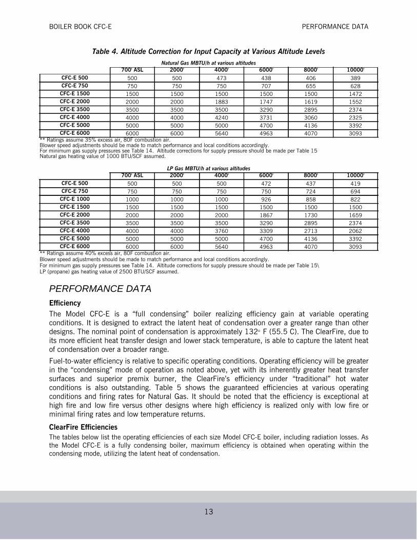
Table 4. Altitude Correction for Input Capacity at Various Altitude Levels
PERFORMANCE DATAEfficiencyThe Model CFC-E is a “full condensing” boiler realizing efficiency gain at variable operatingconditions. It is designed to extract the latent heat of condensation over a greater range than otherdesigns. The nominal point of condensation is approximately 132 F (55.5 C). The ClearFire, due toits more efficient heat transfer design and lower stack temperature, is able to capture the latent heatof condensation over a broader range.
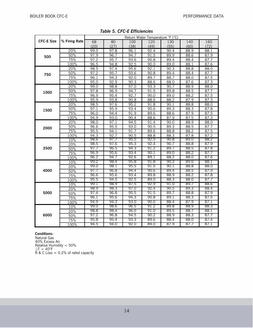
Fuel-to-water efficiency is relative to specific operating conditions. Operating efficiency will be greaterin the “condensing” mode of operation as noted above, yet with its inherently greater heat transfersurfaces and superior premix burner, the ClearFire’s efficiency under “traditional” hot waterconditions is also outstanding. Table 5 shows the guaranteed efficiencies at various operatingconditions and firing rates for Natural Gas. It should be noted that the efficiency is exceptional athigh fire and low fire versus other designs where high efficiency is realized only with low fire orminimal firing rates and low temperature returns.
ClearFire EfficienciesThe tables below list the operating efficiencies of each size Model CFC-E boiler, including radiation losses. Asthe Model CFC-E is a fully condensing boiler, maximum efficiency is obtained when operating within thecondensing mode, utilizing the latent heat of condensation.
Natural Gas MBTU/h at various altitudes700' ASL 2000' 4000' 6000' 8000' 10000'
CFC-E 500 500 500 473 438 406 389CFC-E 750 750 750 750 707 655 628
CFC-E 1500 1500 1500 1500 1500 1500 1472CFC-E 2000 2000 2000 1883 1747 1619 1552CFC-E 3500 3500 3500 3500 3290 2895 2374CFC-E 4000 4000 4000 4240 3731 3060 2325CFC-E 5000 5000 5000 5000 4700 4136 3392CFC-E 6000 6000 6000 5640 4963 4070 3093
** Ratings assume 35% excess air, 80F combustion air.Blower speed adjustments should be made to match performance and local conditions accordingly.For minimum gas supply pressures see Table 14. Altitude corrections for supply pressure should be made per Table 15Natural gas heating value of 1000 BTU/SCF assumed.
LP Gas MBTU/h at various altitudes700' ASL 2000' 4000' 6000' 8000' 10000'
CFC-E 500 500 500 500 472 437 419CFC-E 750 750 750 750 750 724 694
CFC-E 1000 1000 1000 1000 926 858 822CFC-E 1500 1500 1500 1500 1500 1500 1500CFC-E 2000 2000 2000 2000 1867 1730 1659CFC-E 3500 3500 3500 3500 3290 2895 2374CFC-E 4000 4000 4000 3760 3309 2713 2062CFC-E 5000 5000 5000 5000 4700 4136 3392CFC-E 6000 6000 6000 5640 4963 4070 3093
** Ratings assume 40% excess air, 80F combustion air.Blower speed adjustments should be made to match performance and local conditions accordingly.For minimum gas supply pressures see Table 14. Altitude corrections for supply pressure should be made per Table 15\LP (propane) gas heating value of 2500 BTU/SCF assumed.
BOILER BOOK CFC-E PERFORMANCE DATA
14
Table 5. CFC-E Efficiencies
CFC-E Size % Firing RateReturn Water Temperature °F (°C)
68 80 100 120 130 140 160(20) (27) (38) (49) (55) (60) (72)
500
20% 99.0 97.8 96.1 92.4 90.4 88.9 88.150% 97.9 96.7 94.7 91.5 89.9 88.6 87.975% 97.2 95.7 93.6 90.8 89.4 88.4 87.7100% 96.5 94.8 92.5 90.0 89.0 88.1 87.6
750
20% 98.5 97.4 95.6 92.1 90.3 88.8 88.050% 97.2 95.7 93.6 90.8 89.4 88.4 87.775% 96.1 94.3 92.0 89.7 88.7 88.0 87.5100% 95.0 92.9 90.3 88.6 88.0 87.6 87.3
1000
20% 99.0 98.8 97.0 93.3 90.7 88.9 88.050% 97.8 96.9 94.7 91.5 89.8 88.5 87.775% 96.9 95.4 92.7 90.0 89.0 88.2 87.5100% 95.9 93.8 90.8 88.6 88.2 87.9 87.3
1500
20% 98.5 97.6 95.2 91.8 90.1 88.8 88.050% 97.1 95.9 93.4 90.6 89.3 88.3 87.875% 96.0 94.4 91.9 89.6 88.6 87.9 87.5100% 94.9 93.0 90.4 88.6 87.9 87.5 87.3
2000
20% 98.0 97.1 94.5 91.4 90.0 88.9 88.050% 96.6 95.5 93.0 90.5 89.3 88.5 87.775% 95.5 94.1 91.7 89.6 88.8 88.2 87.5100% 94.3 92.7 90.5 88.8 88.3 87.8 87.2
3500
10% 98.6 97.7 95.5 92.5 90.8 89.0 88.220% 98.5 97.6 95.3 92.4 90.7 88.8 87.950% 97.7 96.5 94.3 91.2 89.7 88.5 87.875% 96.9 95.6 93.4 90.1 89.0 88.2 87.7
100% 96.2 94.7 92.6 89.1 88.2 88.0 87.6
4000
10% 99.2 98.4 95.8 91.8 90.3 89.0 88.120% 99.0 98.1 95.5 91.5 90.1 88.8 88.050% 97.7 96.8 94.4 90.6 89.4 88.5 87.975% 96.6 95.6 93.4 89.8 88.9 88.2 87.8
100% 95.5 94.5 92.5 89.0 88.3 88.0 87.7
5000
10% 99.1 98.9 97.5 92.9 91.0 89.7 88.620% 98.9 98.3 97.0 92.4 90.5 89.3 88.450% 97.4 96.8 95.5 91.5 89.7 88.8 87.975% 96.1 95.6 94.3 90.8 89.1 88.3 87.5
100% 94.9 94.3 93.0 90.0 88.4 87.9 87.1
6000
10% 99.0 98.6 96.5 91.2 89.8 88.9 88.320% 98.8 98.4 96.0 91.0 89.5 88.7 88.150% 97.2 96.8 94.5 90.2 88.9 88.3 87.775% 95.8 95.4 93.3 89.6 88.4 88.0 87.4
100% 94.5 94.0 92.0 89.0 87.9 87.7 87.1
Conditions:Natural Gas40% Excess AirRelative Humidity = 50%∆T = 40°FR & C Loss = 0.2% of rated capacity
BOILER BOOK CFC-E PERFORMANCE DATA
15
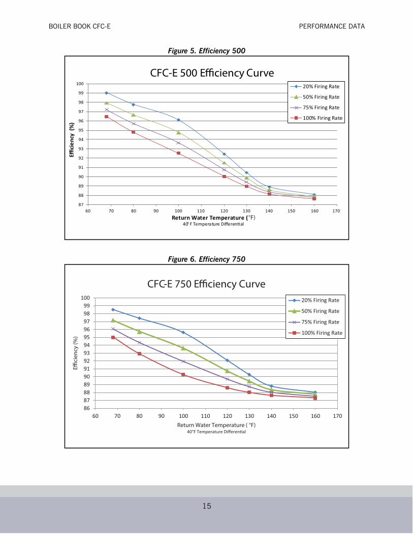
Figure 5. Efficiency 500
Figure 6. Efficiency 750
87
88
89
90
91
92
93
94
95
96
97
98
99
100
60 70 80 90 100 110 120 130 140 150 160 170
Ecie
ncy
(%)
Return Water Temperature (40° F Temperature Di eren al
CFC-E 500 Efficiency Curve20% Firing Rate
50% Firing Rate
75% Firing Rate
100% Firing Rate
°F)
8687888990919293949596979899
100
60 70 80 90 100 110 120 130 140 150 160 170
Effici
ency
(%)
Return Water Temperature ( °F)40°F Temperature Di eren al
CFC-E 750 Efficiency Curve20% Firing Rate
50% Firing Rate
75% Firing Rate
100% Firing Rate

BOILER BOOK CFC-E PERFORMANCE DATA
16
Figure 7. Efficiency 1000
Figure 8. Efficiency 1500
8687888990919293949596979899
100
60 70 80 90 100 110 120 130 140 150 160 170
Effici
ency
(%)
Return Water Temperature ( °F)40°F Temperature Di eren al
CFC-E 1000 Efficiency Curve20% Firing Rate
50% Firing Rate
75% Firing Rate
100% Firing Rate
8687888990919293949596979899
100
60 70 80 90 100 110 120 130 140 150 160 170
Effici
ency
(%)
Return Water Temperature ( °F)40°F Temperature Di eren al
CFC-E 1500 Efficiency Curve20% Firing Rate
50% Firing Rate
75% Firing Rate
100% Firing Rate

BOILER BOOK CFC-E PERFORMANCE DATA
17
Figure 9. Efficiency 2000
Figure 10. Efficiency 3500
8687888990919293949596979899
60 70 80 90 100 110 120 130 140 150 160 170
Effici
ency
(%)
Return Water Temperature ( °F)40°F Temperature Di eren al
CFC-E 2000 Efficiency Curve20% Firing Rate
50% Firing Rate
75% Firing Rate
100% Firing Rate
85
86
87
88
89
90
91
92
93
94
95
96
97
98
99
100
60 70 80 90 100 110 120 130 140 150 160 170
10% Firing Rate
20% Firing Rate
50% Firing Rate
75% Firing Rate
100% Firing Rate
Effici
ency
(%)
Return Water Temperature ( °F)40°F Temperature Di eren al
CFC-E 3500 Efficiency Curve

BOILER BOOK CFC-E PERFORMANCE DATA
18
Figure 11. Efficiency 4000
Figure 12. Efficiency 5000
10% Firing Rate
20% Firing Rate
50% Firing Rate
75% Firing Rate
100% Firing Rate
85
86
87
88
89
90
91
92
93
94
95
96
97
98
99
100
60 70 80 90 100 110 120 130 140 150 160 170
Effici
ency
(%)
Return Water Temperature ( °F)40°F Temperature Di eren al
CFC-E 4000 Efficiency CurveEffi
cien
cy (%
)
Return Water Temperature ( °F)40°F Temperature Di eren al
CFC-E 5000 Efficiency Curve
85
86
87
88
89
90
91
92
93
94
95
96
97
98
99
100
60 70 80 90 100 110 120 130 140 150 160 170
20% Firing Rate
50% Firing Rate
75% Firing Rate
100% Firing Rate
10% Firing Rate

BOILER BOOK CFC-E PERFORMANCE DATA
19
Figure 13. Efficiency 6000
EmissionsBy means of the Pre-mix burner, the Clearfire boiler provides environmentally friendly emissionswhen firing natural gas; emission data are shown below.
Table 6. Emissions
*ppm levels are given on a dry volume basis and corrected to 3% oxygen (15% excess air)
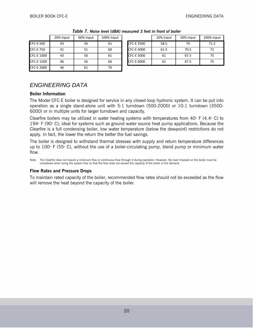
Noise LevelThe Model CFC-E is extremely quiet at all operating levels, does not require any sound levelmodifications to provide ultra low noise levels, and is virtually vibration free. Thus, it is very suitablein applications that demand low noise levels.
POLLUTANT UNITS
COppm* <20
lb/MMBTU <0.014
NOxppm* <20
lb/MMBTU <0.024
SOxppm* <1
lb/MMBTU <0.001
HC/VOCppm* <4
lb/MMBTU <0.0016
PMppm* -
lb/MMBTU <0.01
85
86
87
88
89
90
91
92
93
94
95
96
97
98
99
100
60 70 80 90 100 110 120 130 140 150 160 170
Effici
ency
(%)
Return Water Temperature ( °F)40°F Temperature Di eren al
CFC-E 6000 Efficiency Curve
20% Firing Rate
50% Firing Rate
75% Firing Rate
100% Firing Rate
10% Firing Rate
BOILER BOOK CFC-E ENGINEERING DATA
20
Table 7. Noise level (dBA) measured 3 feet in front of boiler
ENGINEERING DATABoiler InformationThe Model CFC-E boiler is designed for service in any closed-loop hydronic system. It can be put intooperation as a single stand-alone unit with 5:1 turndown (500-2000) or 10:1 turndown (3500-6000) or in multiple units for larger turndown and capacity.
Clearfire boilers may be utilized in water heating systems with temperatures from 40 F (4.4 C) to194 F (90 C); ideal for systems such as ground water source heat pump applications. Because theClearfire is a full condensing boiler, low water temperature (below the dewpoint) restrictions do notapply. In fact, the lower the return the better the fuel savings.
The boiler is designed to withstand thermal stresses with supply and return temperature differencesup to 100 F (55 C), without the use of a boiler-circulating pump, blend pump or minimum waterflow.
Note: The Clearfire does not require a minimum flow or continuous flow through it during operation. However, the load imposed on the boiler must be considered when sizing the system flow so that the flow does not exceed the capacity of the boiler or the demand.
Flow Rates and Pressure DropsTo maintain rated capacity of the boiler, recommended flow rates should not be exceeded as the flowwill remove the heat beyond the capacity of the boiler.
20% Input 60% Input 100% Input 10% Input 50% Input 100% InputCFC-E 500 43 56 61 CFC-E 3500 58.5 70 71.2CFC-E 750 41 51 60 CFC-E 4000 61.5 70.5 72CFC-E 1000 43 56 61 CFC-E 5000 61 67.5 75CFC-E 1500 46 56 66 CFC-E 6000 61 67.5 75CFC-E 2000 46 61 70
BOILER BOOK CFC-E ENGINEERING DATA
21
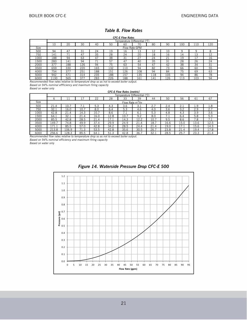
Table 8. Flow Rates
Figure 14. Waterside Pressure Drop CFC-E 500
CFC-E Flow RatesTemperature Differential (°F)
10 20 30 40 50 60 70 80 90 100 110 120Size Flow Rate GPM500 94 47 31 24 19 16 13 12 10 9 9 8750 141 71 47 35 28 24 20 18 16 14 13 121000 188 94 63 47 38 31 27 24 21 19 17 161500 283 141 94 71 57 47 40 35 31 28 26 242000 377 188 126 94 75 63 54 47 42 38 34 313500 659 330 220 165 132 110 94 82 73 66 60 554000 754 377 251 188 151 126 108 94 84 75 69 635000 942 471 314 235 188 157 135 118 105 94 86 786000 1130 565 377 283 226 188 161 141 126 113 103 94
Recommended flow rates relative to temperature drop so as not to exceed boiler output.Based on 94% nominal effficiency and maximum firing capacityBased on water only
CFC-E Flow Rates [metric]Temperature Differential (°C)
6 11 17 22 28 33 39 44 50 56 61 67Size Flow Rate m3/hr500 21.4 10.7 7.1 5.3 4.3 3.6 3.1 2.7 2.4 2.1 1.9 1.8750 32.1 16.0 10.7 8.0 6.4 5.3 4.6 4.0 3.6 3.2 2.9 2.71000 42.8 21.4 14.3 10.7 8.6 7.1 6.1 5.3 4.8 4.3 3.9 3.61500 64.1 32.1 21.4 16.0 12.8 10.7 9.2 8.0 7.1 6.4 5.8 5.32000 85.5 42.8 28.5 21.4 17.1 14.3 12.2 10.7 9.5 8.6 7.8 7.13500 149.7 74.8 49.9 37.4 29.9 24.9 21.4 18.7 16.6 15.0 13.6 12.54000 171.1 85.5 57.0 42.8 34.2 28.5 24.4 21.4 19.0 17.1 15.6 14.35000 213.8 106.9 71.3 53.5 42.8 35.6 30.5 26.7 23.8 21.4 19.4 17.86000 256.6 128.3 85.5 64.1 51.3 42.8 36.7 32.1 28.5 25.7 23.3 21.4
Recommended flow rates relative to temperature drop so as not to exceed boiler output.Based on 94% nominal efficiency and maximum firing capacityBased on water only
0.0
0.1
0.2
0.3
0.4
0.5
0.6
0.7
0.8
0.9
1.0
1.1
1.2
0 5 10 15 20 25 30 35 40 45 50 55 60 65 70 75 80 85 90 95
Pres
sure
(psi)
Flow Rate (gpm)
BOILER BOOK CFC-E ENGINEERING DATA
22
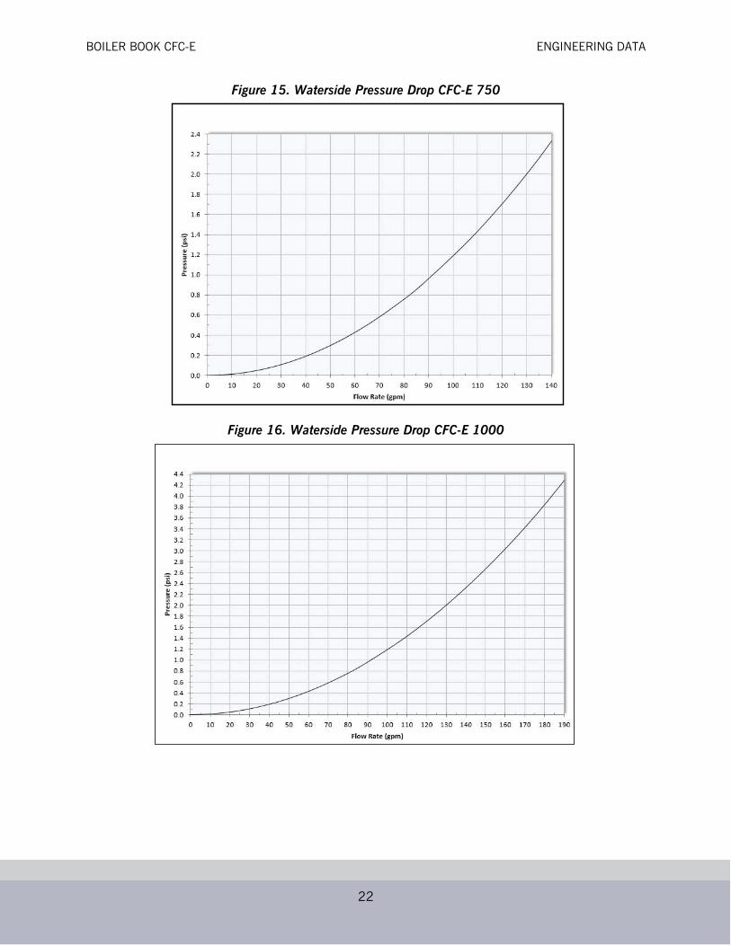
Figure 15. Waterside Pressure Drop CFC-E 750
Figure 16. Waterside Pressure Drop CFC-E 1000

BOILER BOOK CFC-E ENGINEERING DATA
23
Figure 17. Waterside Pressure Drop CFC-E 1500
Figure 18. Waterside Pressure Drop CFC-E 2000
BOILER BOOK CFC-E ENGINEERING DATA
24
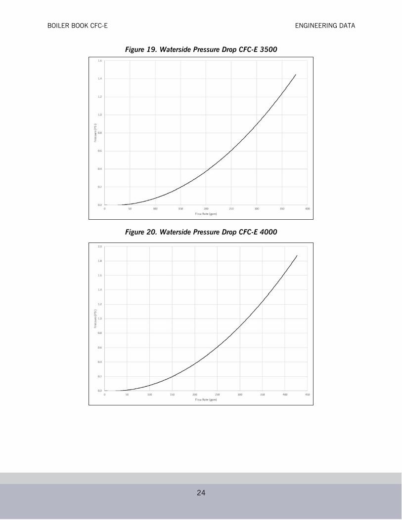
Figure 19. Waterside Pressure Drop CFC-E 3500
Figure 20. Waterside Pressure Drop CFC-E 4000

BOILER BOOK CFC-E ENGINEERING DATA
25
Figure 21. Waterside Pressure Drop CFC-E 5000
Figure 22. Waterside Pressure Drop CFC-E 6000
BOILER BOOK CFC-E ENGINEERING DATA
26
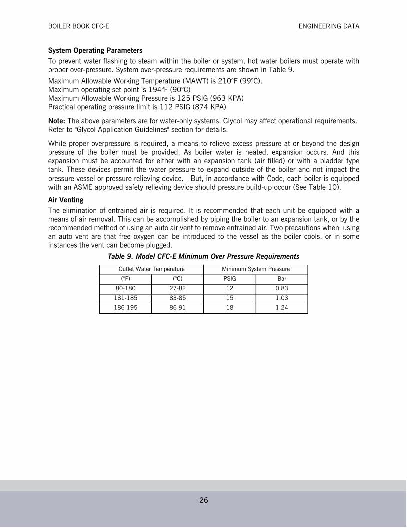
System Operating ParametersTo prevent water flashing to steam within the boiler or system, hot water boilers must operate withproper over-pressure. System over-pressure requirements are shown in Table 9.
Maximum Allowable Working Temperature (MAWT) is 210°F (99°C).Maximum operating set point is 194°F (90°C)Maximum Allowable Working Pressure is 125 PSIG (963 KPA)Practical operating pressure limit is 112 PSIG (874 KPA)
Note: The above parameters are for water-only systems. Glycol may affect operational requirements. Refer to "Glycol Application Guidelines" section for details.
While proper overpressure is required, a means to relieve excess pressure at or beyond the designpressure of the boiler must be provided. As boiler water is heated, expansion occurs. And thisexpansion must be accounted for either with an expansion tank (air filled) or with a bladder typetank. These devices permit the water pressure to expand outside of the boiler and not impact thepressure vessel or pressure relieving device. But, in accordance with Code, each boiler is equippedwith an ASME approved safety relieving device should pressure build-up occur (See Table 10).
Air VentingThe elimination of entrained air is required. It is recommended that each unit be equipped with ameans of air removal. This can be accomplished by piping the boiler to an expansion tank, or by therecommended method of using an auto air vent to remove entrained air. Two precautions when usingan auto vent are that free oxygen can be introduced to the vessel as the boiler cools, or in someinstances the vent can become plugged.
Table 9. Model CFC-E Minimum Over Pressure Requirements
Outlet Water Temperature Minimum System Pressure
(°F) (°C) PSIG Bar
80-180 27-82 12 0.83
181-185 83-85 15 1.03
186-195 86-91 18 1.24

BOILER BOOK CFC-E ENGINEERING DATA
27
Table 10. Safety Relief Valve Information
@125 psig @60 psigModel Inlet (NPT) Outlet (NPT) Valve Capacity (MBH) Model Inlet (NPT) Outlet (NPT) Valve Capacity (MBH)
CFC-E 500 3/4” 1” 3364 CFC-E 500 3/4” 1” 1785CFC-E 750 3/4” 1” 3364 CFC-E 750 3/4” 1” 1785CFC-E 1000 3/4” 1” 3364 CFC-E 1000 3/4” 1” 1785CFC-E 1500 3/4” 1” 3364 CFC-E 1500 3/4” 1” 1785CFC-E 2000 3/4” 1” 3364 CFC-E 2000 1” 1-1/4” 2789CFC-E 3500 1” 1-1/4” 5258 CFC-E 3500 1-1/2” 2” 5919CFC-E 4000 1” 1-1/4” 5258 CFC-E 4000 1-1/2” 2” 5919CFC-E 5000 1” 1-1/4” 5258 CFC-E 5000 1-1/2” 2” 5919CFC-E 6000 1-1/2” 2” 11152 CFC-E 6000 2” 2-1/2” 10525
@100 psig @50 psigModel Inlet (NPT) Outlet (NPT) Valve Capacity (MBH) Model Inlet (NPT) Outlet (NPT) Valve Capacity (MBH)
CFC-E 500 3/4” 1” 2756 CFC-E 500 3/4” 1” 1540CFC-E 750 3/4” 1” 2756 CFC-E 750 3/4” 1” 1540CFC-E 1000 3/4” 1” 2756 CFC-E 1000 3/4” 1” 1540CFC-E 1500 3/4” 1” 2756 CFC-E 1500 3/4” 1” 1540CFC-E 2000 3/4” 1” 2756 CFC-E 2000 1” 1-1/4” 2407CFC-E 3500 1” 1-1/4” 4308 CFC-E 3500 1-1/4” 1-1/2” 3969CFC-E 4000 1” 1-1/4” 4308 CFC-E 4000 1-1/2” 2” 5107CFC-E 5000 1-1/2” 2” 9137 CFC-E 5000 1-1/2” 2” 5107CFC-E 6000 1-1/2” 2” 9137 CFC-E 6000 2” 2-1/2” 9082
@80 psig @30 psigModel Inlet (NPT) Outlet (NPT) Valve Capacity (MBH) Model Inlet (NPT) Outlet (NPT) Valve Capacity (MBH)
CFC-E 500 3/4” 1” 2270 CFC-E 500 1” 1-1/4” 1649CFC-E 750 3/4” 1” 2270 CFC-E 750 1” 1-1/4” 1649CFC-E 1000 3/4” 1” 2270 CFC-E 1000 1” 1-1/4” 1649CFC-E 1500 3/4” 1” 2270 CFC-E 1500 1” 1-1/4” 2716CFC-E 2000 3/4” 1” 2270 CFC-E 2000 1-1/4” 1-1/2” 6215CFC-E 3500 1” 1-1/4” 3548 CFC-E 3500 2” 2-1/2” 6215CFC-E 4000 1-1/2” 2” 7525 CFC-E 4000 2” 2-1/2” 6215CFC-E 5000 1-1/2” 2” 7525 CFC-E 5000 2” 2-1/2” 6215CFC-E 6000 1-1/2” 2” 7525 CFC-E 6000 2” 2-1/2” 1649
@75 psigModel Inlet (NPT) Outlet (NPT) Valve Capacity (MBH)
CFC-E 500 3/4” 1” 2148CFC-E 750 3/4” 1” 2148CFC-E 1000 3/4” 1” 2148CFC-E 1500 3/4” 1” 2148CFC-E 2000 3/4” 1” 2148CFC-E 3500 1-1/2” 2” 7122CFC-E 4000 1-1/2” 2” 7122CFC-E 5000 1-1/2” 2” 7122CFC-E 6000 1-1/2” 2” 7122

BOILER BOOK CFC-E ENGINEERING DATA
28
Water TreatmentEven though hot water systems are “closed”, some amount of make-up water (up to 10%) will beintroduced. This more often than not happens from seal leaks of pumps, or other minimal leaks fromvalves etc., that go unnoticed. Therefore, proper water chemistry of a hot water boiler is necessaryfor good operation and longevity, particularly to ensure that free oxygen and contaminants areremoved to prevent waterside corrosion or scale buildup. A make-up water meter is recommended tomonitor the amount of make-up water being introduced into the system.
Table 11. Model CFC-E Water Chemistry Requirements in accordance with ABMA
Glycol Application GuidelinesThe Model CFC-E boiler may be operated with a solution of glycol and water. Where glycols areadded, the system must first be cleaned and flushed. Correct glycol selection and regular monitoringof the in-use concentration and its stability is essential to ensure adequate, long-term freezeprotection, including protection from the effects of glycol-derived corrosion resulting from glycoldegradation.
Typically, ethylene glycol is used for freeze protection, but other alternatives exist, such as propyleneglycol. Glycol reduces the water-side heat capacity (lower specific heat than 100% water) and willreduce the effective heat transfer to the system. Because of this, design flow rates and pumpselections should be sized with this in mind.
Generally, corrosion inhibitors are added to glycol systems. However, all glycols tend to oxidize overtime in the presence of oxygen, and when heated, form aldehydes, acids, and other oxidationproducts. Whenever inadequate levels of water treatment buffers and corrosion inhibitors are used,the resulting water glycol mixture pH may be reduced to below 7.0 (frequently reaching 5) and acidcorrosion results. Thus, when pH levels drop below 7.0 due to glycol degradation the onlyalternative is to drain, flush, repassivate, and refill with a new inhibited glycol solution.
The following recommendations should be adhered to in applying ClearFire model CFC-E boilers tohydronic systems using glycol:
1) Maximum allowable antifreeze proportion (volume%): 50% antifreeze (glycol)50% water
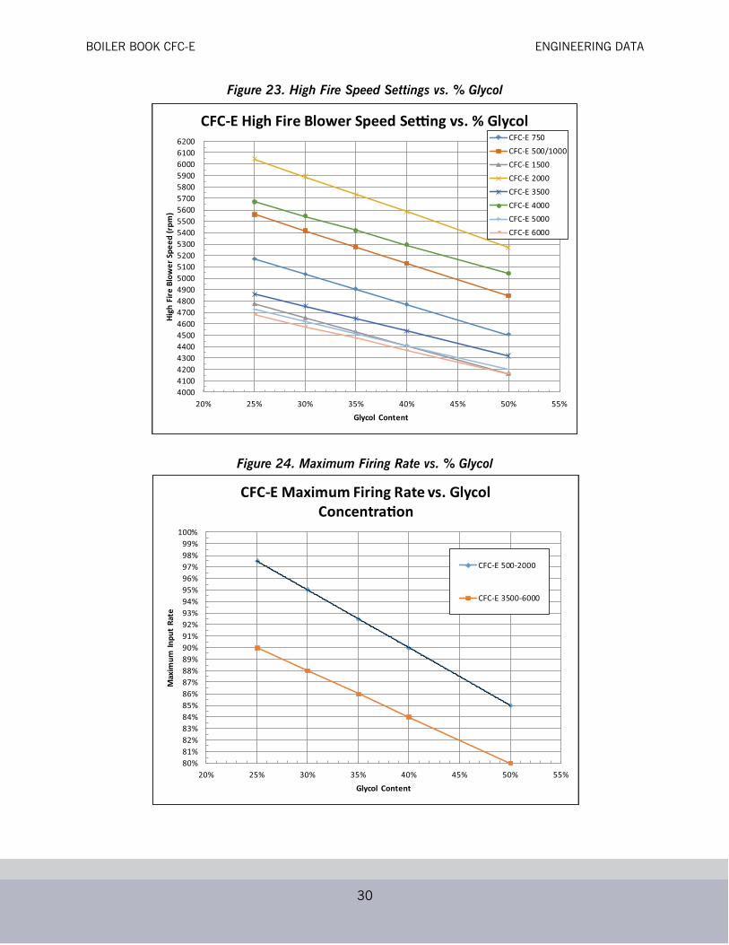
2) High temperature glycol recommended.3) The glycol concentration determines the maximum allowable firing rate and output of the boiler(s). Please refer to
the firing rate limitation and corresponding high fire speed settings vs. glycol% in the charts below.4) Maximum allowable boiler outlet/supply temperature: 185 deg F (85 deg C).5) Minimum water circulation through the boiler:
Parameter LimitGlycol 50%
pH 8.3 - 10.5Nitrates 50 ppmSulfates 50 ppmChloride < 250 ppmOxygen < 0.1 ppm
Specific Conductivity < 3500 mmho/cmTotal Hardness < 10 ppm

BOILER BOOK CFC-E ENGINEERING DATA
29
a) The minimum water circulation must be defined in such a way that the temperature difference betweenthe boiler outlet/supply and inlet/return is a maximum of 40 deg F (22 deg C), defined as DT (Delta T).A DT Limit algorithm should be enabled in the boiler controller.
b) Independent from the hydraulics of the heating system, constant water circulation through each boiler isrequired while the boiler is operating (requires a dedicated boiler pump if in a primary/secondary looparrangement). Refer to table below for minimum boiler circulation rates.
5) Minimum over-pressure at the boiler:For outlet temperatures up to the maximum of 185 deg F (85 deg C), a minimum operating pressure of 30 psig(2.1 bar) is required.
6) pH level should be maintained between 8.3 and 10.57) It is recommended to maintain continuous circulation in glycol systems. Where this is impractical (e.g. multiple
boiler systems), a periodic pump exercise routine should be implemented to ensure proper mixture of glycol and toavoid degradation that naturally occurs with glycol mixtures. This can be as simple as opening a boiler isolationvalve once a day or turning on a boiler circulating pump.
Table 12. Glycol Minimum Flow Recommendations for ClearFire Model CFC-E Boiler(Minimum required boiler circulation rate (gpm) at maximum firing rate.)
Notes/Limitations:1. Maximum firing rate determined by ClearFire CFC-E Glycol Firing Rate Limitation chart (below). Maximum high fire
blower speed set according to chart.2. Glycol concentration of 25%-50%. Minimum required system operating pressure is 30 psig.3. Maximum system operating temperature of 185 ˚F. Maximum ∆T of 40˚.4. Circulation rates correlate with boiler output based on 92% nominal efficiency.5. Standard altitude (<1000' ASL). Contact Cleaver-Brooks for high altitude applications.6. Pumps should be sized based on system design ∆T and minimum required flow rates.7. At minimum firing rate, the minimum circulation rate should correspond to the boiler's turndown.
System ∆T (˚F)Model-Size ∆T = 10˚ ∆T = 20˚ ∆T = 30˚ ∆T = 40˚CFC-E 500 95 47 32 24CFC-E 750 142 71 47 36CFC-E 1000 190 95 63 47CFC-E 1500 285 142 95 71CFC-E 2000 380 190 127 95CFC-E 3500 614 307 205 153CFC-E 4000 701 351 234 175CFC-E 5000 877 438 292 219CFC-E 6000 1052 526 351 263
BOILER BOOK CFC-E ENGINEERING DATA
30
Figure 23. High Fire Speed Settings vs. % Glycol
Figure 24. Maximum Firing Rate vs. % Glycol
40004100420043004400450046004700480049005000510052005300540055005600570058005900600061006200
20% 25% 30% 35% 40% 45% 50% 55%
High
Fire
Blo
wer
Spe
ed (r
pm)
Glycol Content
CFC-E High Fire Blower Speed Se ng vs. % GlycolCFC-E 750CFC-E 500/1000CFC-E 1500CFC-E 2000CFC-E 3500CFC-E 4000CFC-E 5000CFC-E 6000
80%81%82%83%84%85%86%87%88%89%90%91%92%93%94%95%96%97%98%99%
100%
20% 25% 30% 35% 40% 45% 50% 55%
Max
imum
Inpu
t Ra
te
Glycol Content
CFC-E Maximum Firing Rate vs. Glycol Concentra on
CFC-E 500-2000
CFC-E 3500-6000

BOILER BOOK CFC-E ENGINEERING DATA
31
CondensationThe CFC-E uses one of several condensate removal options, depending on the application:
(1) Condensate direct to drain - The condensate is piped directly to a drain through the piping andwater trap supplied during installation (see Figure 25).
• Piping is to be a minimum of 3/4” NPT.
• Maximum discharge pipe height from floor to be 9”.
• Condensate water trap (5”) required.
(2) Neutralization Capsule - A compact, corrosion resistant capsule is piped to the condensate draindownstream of the water trap. Capsule is filled with a replaceable neutralizing agent.
The neutralization media will require periodic replacement, to be determined by pH analysis ofcondensate. If condensate is too acidic (pH is below acceptable value) the neutralization mediashould be replaced.
Capsule is limited to individual boilers 1000 MBH and smaller.
Figure 26. Neutralization Capsule
Figure 25. Condensate Piped Direct to Drain
TODRAIN
FROMBOILER

BOILER BOOK CFC-E ENGINEERING DATA
32
(3) Combo trap/treatment tank - The condensate is held in a condensate tank under the boiler. Thecondensate is neutralized as it passes through the granular bed. The neutralized condensate is thenpiped to the drain.
The combo tank features an integral water trap and float makeup valve.
• To install the system, assemble the tank and neutralization granulate per Figure 27. Two bags of neutralization media are sufficient to fill the tank.
• Install the condensate tank cover and slide the complete assembly under the boiler
Pipe to the appropriate drain.
The neutralization media will require periodic replacement, to be determined by pH analysis ofcondensate. If condensate is too acidic (pH is below acceptable value) the neutralization mediashould be replaced.
The neutralizing media should be gently agitated periodically to ensure even distribution and toavoid channeling of the condensate.
(4) Treatment tank - The condensate is held in a condensate tank(s) under or near the boiler. Thecondensate is neutralized as it passes through a bed of granular material. The neutralizedcondensate is then piped to the drain.
• To install the system, assemble the tank and fittings per instructions supplied with tank. Neutralization media are already installed in tank.
• Install the condensate tank cover and connect tank to boiler condensate discharge.
Pipe to an appropriate drain.
Figure 27. Combo Trap/Tank
NOTE: For CFC-E 500-2000 requiring a condensate tank where the boiler(s) will not be installed on ahousekeeping pad, the combination trap/tank [option (3) above] must be used.
CFC-E 3500-6000 models require a 4" housekeeping pad for proper condensate drainage.
Condensatein
To drain
Float valve for makeup water
Drain trap Neutralization tank
Neutralization media
BOILER BOOK CFC-E ENGINEERING DATA
33
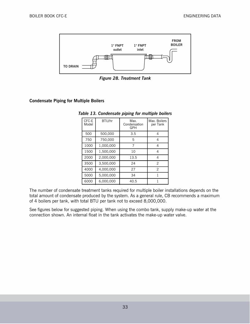
Figure 28. Treatment Tank
Condensate Piping for Multiple Boilers
The number of condensate treatment tanks required for multiple boiler installations depends on the total amount of condensate produced by the system. As a general rule, CB recommends a maximum of 4 boilers per tank, with total BTU per tank not to exceed 8,000,000.
See figures below for suggested piping. When using the combo tank, supply make-up water at the connection shown. An internal float in the tank activates the make-up water valve.
Table 13. Condensate piping for multiple boilers
CFC-E Model
BTU/hr Max. Condensation
GPH
Max. Boilers per Tank
500 500,000 3.5 4
750 750,000 5 4
1000 1,000,000 7 4
1500 1,500,000 10 4
2000 2,000,000 13.5 4
3500 3,500,000 24 2
4000 4,000,000 27 2
5000 5,000,000 34 1
6000 6,000,000 40.5 1
TO DRAIN
1" FNPT outlet
1" FNPT inlet
FROMBOILER
BOILER BOOK CFC-E ENGINEERING DATA
34
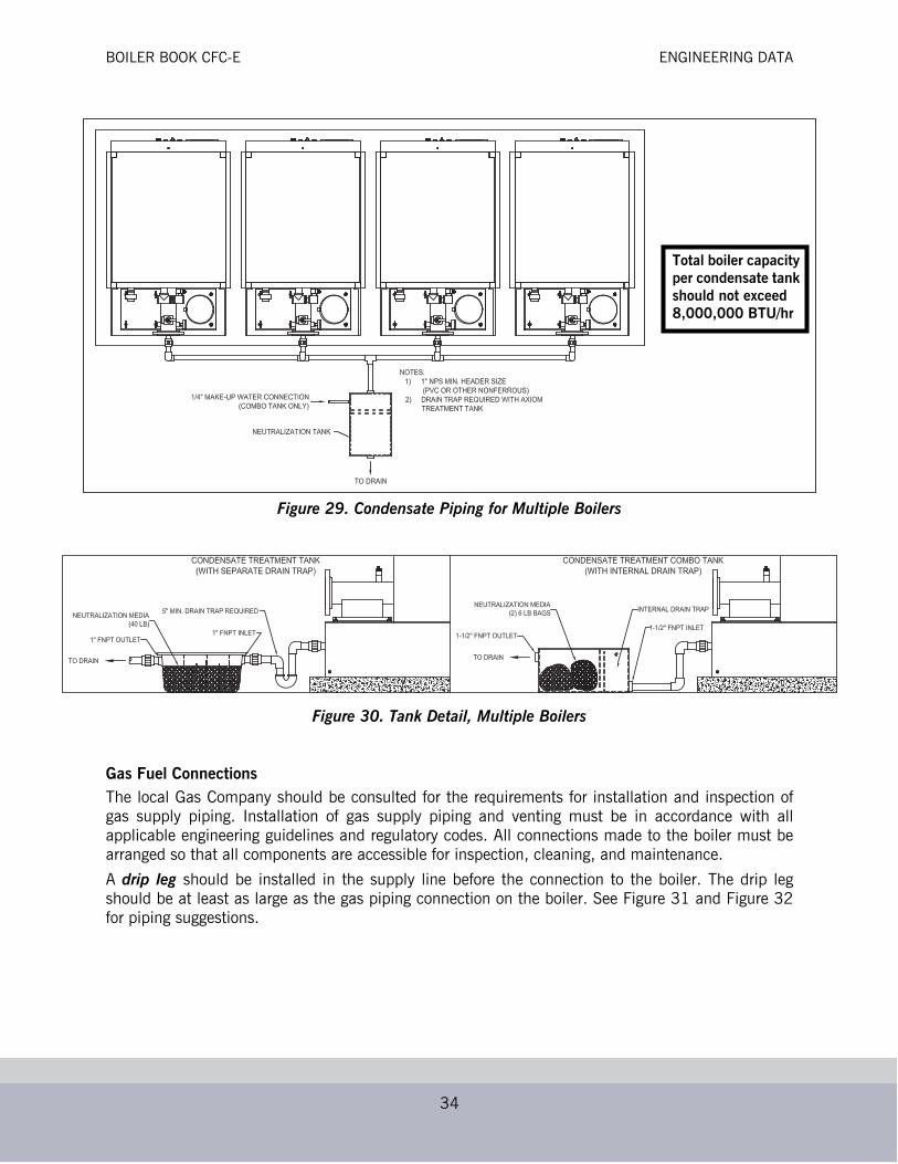
Gas Fuel ConnectionsThe local Gas Company should be consulted for the requirements for installation and inspection ofgas supply piping. Installation of gas supply piping and venting must be in accordance with allapplicable engineering guidelines and regulatory codes. All connections made to the boiler must bearranged so that all components are accessible for inspection, cleaning, and maintenance.
A drip leg should be installed in the supply line before the connection to the boiler. The drip legshould be at least as large as the gas piping connection on the boiler. See Figure 31 and Figure 32for piping suggestions.
Figure 29. Condensate Piping for Multiple Boilers
Figure 30. Tank Detail, Multiple Boilers
Total boiler capacity per condensate tank should not exceed 8,000,000 BTU/hr
BOILER BOOK CFC-E ENGINEERING DATA
35
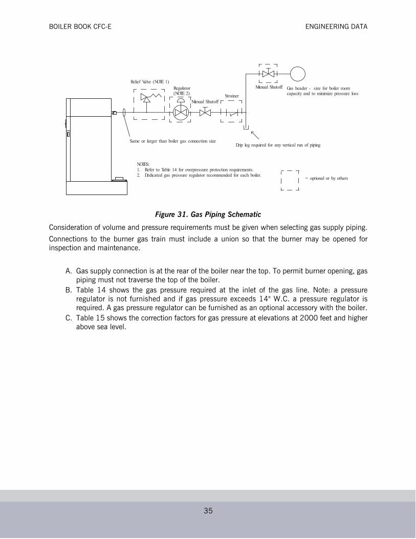
Figure 31. Gas Piping Schematic
Consideration of volume and pressure requirements must be given when selecting gas supply piping.
Connections to the burner gas train must include a union so that the burner may be opened forinspection and maintenance.
A. Gas supply connection is at the rear of the boiler near the top. To permit burner opening, gaspiping must not traverse the top of the boiler.
B. Table 14 shows the gas pressure required at the inlet of the gas line. Note: a pressureregulator is not furnished and if gas pressure exceeds 14" W.C. a pressure regulator isrequired. A gas pressure regulator can be furnished as an optional accessory with the boiler.
C. Table 15 shows the correction factors for gas pressure at elevations at 2000 feet and higherabove sea level.
Same or larger than boiler gas connection sizeDrip leg required for any vertical run of piping
Relief Valve (NOTE 1)Gas header - size for boiler roomcapacity and to minimize pressure loss
Regulator(NOTE 2)
Manual ShutoffStrainer
Manual Shutoff
= optional or by others
NOTES:1. Refer to Table 14 for overpressure protection requirements.2. Dedicated gas pressure regulator recommended for each boiler.
BOILER BOOK CFC-E ENGINEERING DATA
36
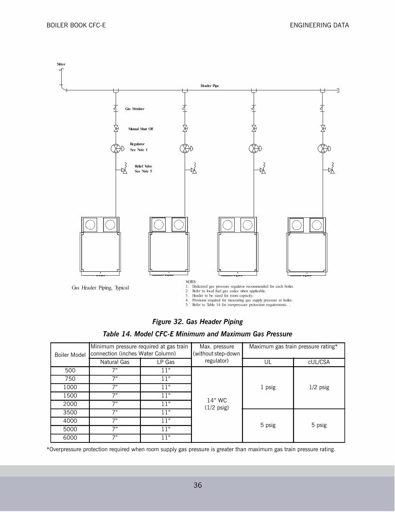
Figure 32. Gas Header Piping
Table 14. Model CFC-E Minimum and Maximum Gas Pressure
*Overpressure protection required when room supply gas pressure is greater than maximum gas train pressure rating.
Boiler ModelMinimum pressure required at gas train connection (inches Water Column)
Max. pressure(without step-down
regulator)
Maximum gas train pressure rating*
Natural Gas LP Gas UL cUL/CSA500 7” 11”
14” WC(1/2 psig)
1 psig 1/2 psig750 7” 11”
1000 7” 11”1500 7” 11”2000 7” 11”3500 7” 11”
5 psig 5 psig4000 7” 11”5000 7” 11”6000 7” 11”
Regulator
Header Pipe
Meter
Gas Header Piping, Typical
Gas Strainer
Relief ValveSee Note 5
Manual Shut Off
See Note 1
NOTES:1. Dedicated gas pressure regulator recommended for each boiler.2. Refer to local fuel gas codes when applicable.3. Header to be sized for room capacity.4. Provision required for measuring gas supply pressure at boiler.5. Refer to Table 14 for overpressure protection requirements. .

BOILER BOOK CFC-E ENGINEERING DATA
37
Table 15. Model CFC-E Minimum Required Gas Pressure Altitude Correction
Boiler Room InformationThe boiler must be installed on a level non-combustible surface. If the surface is not level, a raisedpad, slightly larger than the length and width of the boiler base dimensions, will make boiler levelingpossible. Installing the boiler on a raised pad will make boiler drain connections more accessible andwill keep water from splashing onto the boiler whenever the boiler room floor is washed.
Note: The pad must be of sufficient load bearing strength to safely support the operating weight of the boiler and any additional equipment installed with it. Approximate operating weights are shown in Dimensions and Ratings.
Leveling Once the boiler is placed, it must be leveled side to side and front to back using the supply andreturn nozzles for horizontal and vertical positions. If shims are required to level the boiler, the weightof the boiler must be evenly distributed at all points of support. The optional adjustable feet(available from Cleaver-Brooks) may also be used for leveling.
ClearancesThe boiler must be installed so that all components remain accessible; ensure no overheadobstructions so the burner may be opened. Refer to Figure 33.
Hot Water PipingCFC-E model boilers can be piped variable flow primary or primary/secondary. If primary/secondary,variable speed or on/off boiler pumps may be utilized.
Dedicated boiler circulation pumps are not required with the Model CFC-E boiler. As its design issuch that no minimum flow is required, variable speed or on/off pumps may be employed in thepiping scheme.
Altitude in Feet Correction Factor Altitude in Feet Correction Factor
1000 1.04 6000 1.25
2000 1.07 7000 1.3
3000 1.11 8000 1.35
4000 1.16 9000 1.4
5000 1.21
To obtain minimum required inlet pressure, select altitude of installation and multiply the pressureshown in Table 13 by the correction factor corresponding to the altitude listed above.

BOILER BOOK CFC-E ENGINEERING DATA
38
Figure 33. Model CFC-E Minimum Room Clearance Dimensions
Seismic LegsSeismic mounting details shown below.
Figure 2. CFC-E Seismic Mounting
"B"
"A"
DIM."A""B"
500/750/1000 1500/200034.35”47.4”
35.25”54”
3500/400047.93”66.43”
5000/600058.16”78.63”
FRONT
.56" HOLE(3500-6000)
.44" HOLE(500-2000)
BOILER BOOK CFC-E ENGINEERING DATA
39
Boiler Room Combustion and Ventilation AirThe boiler(s) must be supplied with adequate quantities of uncontaminated air to support propercombustion and equipment ventilation. Air shall be free of chlorides, halogens, fluorocarbons,construction dust or other contaminants that are detrimental to the burner/boiler. If thesecontaminants are present, we recommend the use of direct vent combustion provided the outside airsource is uncontaminated.
Combustion air can be supplied by conventional intake means, where combustion air is drawn fromthe area immediately surrounding the boiler (boiler room must be positive pressure), or with directvent (direct vent combustion) where air is drawn directly from the outside. All installations mustcomply with local Codes and with NFPA 54 (the National Fuel Gas Code - NFGC) for the U.S. and forCanada, CAN/CGA B 149.1 and B 149.2.
For models CFC-E 3500-6000: If using direct venting in a multiple boiler application, an individualair duct is required for each boiler.
For models CFC-E 500-2000, consult your local Cleaver-Brooks representative for combinedcombustion air ductwork consideration.
Note: A boiler room exhaust fan is not recommended as this type of device can cause a negative pressure in the boiler room if using a conventional air intake.
In accordance with NFPA54, the required volume of indoor air shall be determined in accordancewith the “Standard Method” or “Known Air Infiltration Rate Method. Where the air infiltration rate isknown to be less than 0.40 Air Changes per Hour, the Known Air Infiltration Rate Method shall beused. (See Section 8.3 in the NFPA54 Handbook for additional information.)
Combustion Air Supply - Unconfined Spaces (For U.S. Installations Only)A. All Air From Inside the Building - If additional combustion air is drawn from inside the
building (the mechanical equipment room does not receive air from outside via louvers or ventopenings and the boiler is not equipped with direct vent combustion) and the boiler is locatedin a unconfined space, use the following guidelines:
1. The mechanical equipment room must be provided with two permanent openings linked directly with additional room (s) of sufficient volume so that the combined volume of all spaces meet the criteria for an unconfined space. Note: An “unconfined space” is defined as a space whose volume is more than 50 cubic feet per 1,000 Btu per hour of aggregate input rating of all appliances installed in that space.
2. Each opening must have a minimum free area of one square inch per 1,000 Btu per hour of the total input rating of all gas utilizing equipment in the mechanical room.
3. One opening must terminate within twelve inches of the top, and one opening must terminate within twelve inches of the bottom of the room.
4. Refer to the NFGC, Section 8.3 for additional information.

BOILER BOOK CFC-E ENGINEERING DATA
40
Figure 27. Two Opening Outside Wall Method
B. All Air From Outdoors - If all combustion air will be received from outside the building (themechanical room equipment is linked with the outdoors), the following methods can be used:
1. Two Opening Method (Figure 27) - The mechanical equipment room must be provided with two permanent openings, one terminating within twelve inches from the top, and one opening terminating within twelve inches of the bottom of the room.
2. The openings must be linked directly or by ducts with the outdoors.3. Each opening must have a minimum free area of one square inch per 4,000 Btu per hour
of total input rating of all equipment in the room, when the opening is directly linked to the outdoors or through vertical ducts.
4. The minimum free area required for horizontal ducts is one square inch per 2,000 Btu per hour of total input rating of all the equipment in the room.

BOILER BOOK CFC-E ENGINEERING DATA
41
Figure 28. Two Opening Ducted Method
C. One Opening Method (Figure 29) - One permanent opening, commencing within 12 inchesof the top of the enclosure, shall be provided. 1. The equipment shall have clearances of at least 1 inch from the sides and back and 6
inches from the front of the appliance.2. The opening shall directly communicate with the outdoors and shall have a minimum free
area of 1 square inch per 3000 BTU's per hour of the total input rating of all equipment located in the enclosure, and not less than the sum of the areas of all vent connectors in the confined space.
3. Refer to the NFGC, Section 8.3 for additional information.

BOILER BOOK CFC-E ENGINEERING DATA
42
Figure 29. One Opening Method
Unconfined Space/Engineered Design When determining boiler room air requirements for unconfined space, the size of the room, airflow,and velocity of air must be reviewed as follows:
1. Size (area) and location of air supply openings in the boiler room.A. Two permanent air supply openings in the outer walls of the boiler room are recommended.
Locate one at each end of the boiler room, preferably below a height of 7 feet. This allows airto sweep the length of the boiler. See Figure 30.
B. Air supply openings can be louvered for weather protection, but they should not be coveredwith fine mesh wire, as this type of covering has poor air flow qualities and is subject toclogging with dirt and dust.
C. A vent fan in the boiler room is not recommended, as it could create a slight vacuum undercertain conditions and cause variations in the quantity of combustion air. This can result inunsafe burner performance.
D. Under no condition should the total area of the air supply openings be less than one squarefoot.

BOILER BOOK CFC-E ENGINEERING DATA
43
Figure 30. Two Opening Engineered Method
E. Size the openings by using the formula:
Area in square feet = cfm/fpm
Where cfm = cubic feet per minute of air
Where fpm = feet per minute of air
2. Amount of Air Required (cfm).A. Combustion Air = 0.25 cfm per kBtuh.B. Ventilation Air = 0.05 cfm per kBtuh. C. Total air = 0.3 cfm per kBtuh (up to 1000 feet elevation. Add 3% more per 1000 feet of
added elevation).3. Acceptable air velocity in the Boiler Room (fpm).
A. From floor to 7 feet high = 250 fpm.B. Above 7 feet above floor = 500 fpm.
Example: Determine the area of the boiler room air supply openings for (2) Clearfire 1800 boilers at750 feet elevation. The air openings to be 5 feet above floor level.
• Air required: 1800 x 2 = 3600 kBtuh. From 2C above, 3600 x 0.3 = 1,080 cfm.• Air Velocity: Up to 7 feet = 250 fpm from 3 above.• Area required: Area = cfm/fpm = 1,080/250 = 4.32 square feet total.• Area/Opening: 4.32/2 = 2.16 sq-ft/opening (2 required).
Consult local codes, which may supersede these requirements.

BOILER BOOK CFC-E STACK/BREECHING SIZE CRITERIA
44
Boiler Air InletThe boiler ships with both an air inlet screen and a direct vent collar factory mounted on the boiler(see illustration below). If room air will be used for combustion, install the air inlet screen; the collarmay be discarded. If direct venting will be used, install the vent collar; the screen may be discarded.
Mounting hardware is provided with the boiler.
When using direct vent combustion:
1. Provide for adequate ventilation of the boiler room or mechanical equipment room.2. In cold climates, and to mitigate potential freeze-up of the intake pipe, it is highly recommended
that a motorized sealed damper be used to prevent the circulation of cold air through the boiler during non-operating hours.
Figure 31. Boiler Air Inlet
STACK/BREECHING SIZE CRITERIAGeneralBoilers are divided into four categories based on the pressure and temperature produced in theexhaust stack and the likelihood of condensate production in the vent.
• Category I. A boiler which operates with a non-positive vent static pressure and with a vent gas temperature that avoids excessive condensate production in the vent.
• Category II. A boiler which operates with a non-positive vent static pressure and with a vent gas temperature that may cause excessive condensate production in the vent.
• Category III. A boiler which operates with a positive vent pressure and with a vent gas temperature that avoids excessive condensate production in the vent.
• Category IV. A boiler which operates with a positive vent pressure and with a vent gas temperature that may cause excessive condensate production in the vent.
Depending on the application, the Model CFC-E may be considered Category II, III, or IV. Thespecifying engineer should dictate flue venting as appropriate to the installation.In some cases, PVC/CPVC material meeting ULC Type BH Class IIB specifications may be used.Use of PVC/CPVC depends on operating conditions, specific vent suppliers, and any local codeshaving jurisdiction. Refer to vent manufacturer’s specifications for applicability.
Proper installation of flue gas exhaust venting is critical to efficient and safe operation of the ClearfireBoiler. The vent should be supported to maintain proper clearances from combustible materials. Useinsulated vent pipe spacers where the vent passes through combustible roofs and walls.

BOILER BOOK CFC-E STACK/BREECHING SIZE CRITERIA
45
The design of the stack and breeching must provide the required draft at each boiler flue gasconnection; proper draft is critical to burner performance.
Although constant pressure at the flue gas outlet is not required, it is necessary to size the breechingand stack to limit flue gas pressure variation. Consideration of the draft must be given wheneverdirect vent combustion is utilized and lengthy runs of breeching are employed. Please note: Thesystem comprising the stack, breeching, and (if used) direct vent combustion pipe should bedesigned for a range of +/-0.10” W.C. (25 Pa) for proper combustion and lightoff in common ductingapplications. For individual ducting, an operational tolerance of +/-0.25” W.C. (62 Pa) is acceptable.
Whenever two or more boilers are connected to a common breeching/stack, individual stack isolationdampers are required.
Vent TerminationGive special attention to the location of the vent termination to avoid possibility of property damage,compromised performance, or personal injury. For best results with condensing boilers, use verticalstraight (no loss) flue discharge or velocity cone termination. These terminations are suited tomoving flue gases and water vapor away from building exterior surfaces and air intakes.
1. Combustion gases can form a white vapor plume in the winter. The plume could obstruct a window view if the termination is installed in close proximity to windows.
2. Prevailing winds could cause freezing of condensate and water/ice buildup on building, plants orroof.
3. The bottom of the vent terminal, as well as the air intake, shall be located at least 24 inches abovegrade, including normal snow line.
4. Uninsulated single-wall metal vent pipe shall not be used outside in cold climates for ventingcombustion gas.
5. Through-the-wall vents for Category II and IV appliances and non-categorized condensingappliances shall not terminate over public walkways or over an area where condensate or vaporcould create a nuisance or hazard or could be detrimental to the operation of other equipment.Where local experience indicates that condensate is a problem with Category III appliances, thisprovision shall also apply.
6. Locate and guard vent termination to prevent accidental contact by people and pets. 7. DO NOT terminate vent in window well, alcove, stairwell or other recessed area, unless previously
approved by local authority. 8. DO NOT terminate above any door, window, or gravity air intake. Condensate can freeze causing
ice formations. 9. Locate or guard vent to prevent condensate from damaging exterior finishes. Use a 2' x 2' rust
resistant sheet metal backing plate against brick or masonry surfaces. Extend the termination atleast 2” from exterior surface.
10. DO NOT extend exposed stack pipe outside of building. In winter conditions condensate couldfreeze and block stack pipe.
Note: During winter months check the vent cap and make sure no blockage occurs from build up of snow. Condensate can freeze on the vent cap. Frozen condensate on the vent cap can result in a blocked flue condition.

BOILER BOOK CFC-E STACK/BREECHING SIZE CRITERIA
46
U.S. Installations
Refer to the latest edition of the National Fuel Gas Code/NFPA 54. Vent termination requirements are:
1. Vent must terminate at least four feet below and four feet horizontally or one foot above any door, window or gravity air inlet to the building.
2. The vent must be at least seven feet above grade when located adjacent to public walkways.3. Terminate vent at least three feet above any forced air inlet located within ten feet.4. Vent must terminate at least four feet horizontally, and in no case above or below unless four feet
horizontal distance is maintained, from electric meters, gas meters, regulators, and relief equipment.
5. Terminate vent at least six feet from adjacent walls.6. DO NOT terminate vent closer than five feet below roof overhang.
Canadian Installations
Refer to the latest edition of CAN/CSA-B149.1 and B149.2. Vent shall not terminate:
1. Directly above a paved sidewalk or driveway which is located between two single-family dwellings and serves both dwellings.
2. Less than 7 feet (2.31m) above a paved sidewalk or paved driveway located on public property.3. Within 6 feet (1.8m) of a mechanical air supply inlet to any building.4. Above a meter/regulator assembly with 3 feet (900mm) horizontally of the vertical centerline of
the regulator.5. Within 6 feet (1.8m) of any gas service regulator vent outlet.6. Less than 1 foot (300mm) above grade level.7. Within 3 feet (1m) of a window or door which can be opened in any building, any non-
mechanical air supply inlet to any building or to the combustion air inlet of any other appliance.8. Underneath a veranda, porch, or deck unless:
A. The veranda, porch, or deck is fully open on a minimum of two sides beneath the floor.B. The distance between the top of the vent termination and the underside of the veranda, porch,
or deck is greater than one foot (300mm).
Horizontal Through the Wall Venting
Venting configurations using inside air for combustion (See Figure 32)
These installations utilize the boiler-mounted blower to vent the combustion products to the outside.Combustion air is obtained from inside the room and the exhaust vent is installed horizontallythrough the wall to the exterior of the building. Adequate combustion and ventilation air must besupplied to the boiler room in accordance with the NFGC/NFPA 54 for the U.S. and in Canada, thelatest edition of CAN/CSA-B149.1 and.2 Installation Code for Gas Burning Appliances andEquipment.

BOILER BOOK CFC-E STACK/BREECHING SIZE CRITERIA
47
Figure 32. Horizontal through-wall venting using inside air for combustion
The vent must be installed to prevent the potential accumulation of stack condensate in thehorizontal run of vent pipe. Therefore, it is recommended that the vent shall be installed with a slightslope of not more than 1/4” per foot of horizontal run. Breeching should be pitched either towardsthe boiler or the vent termination depending on layout specifics. Review specific layout requirementsand install per stack manufacturer's recommendations.
Note: For installations in cold/freezing climates, it is recommended that:
1. The vent shall be installed with a slight upward slope of not more than 1/4" per foot of horizontal run to the vent termination. In this case, an approved Condensate trap must be installed per applicable codes.
2. The vent must be insulated through the length of horizontal run.
The stack vent cap MUST be mounted on the exterior of the building. The stack vent cap cannot beinstalled in a well or below grade. The stack vent cap must be installed at least two feet aboveground level and above normal snow levels.
The stainless steel direct vent cap must be furnished in accordance with AGA/CGA requirements.
Refer to table for the recommended sizes of horizontal vent pipe.
24” Minimum
Flue Gas Vent(w/Screen)
Inside AirCombustion Itake

BOILER BOOK CFC-E STACK/BREECHING SIZE CRITERIA
48
Horizontal Through the Wall Stack Venting, Direct Vent Combustion (See Figure 33)
Figure 33. Horizontal flue through-wall with direct vent combustion intake
These installations utilize the boiler-mounted blower to take combustion air from the outside andvent combustion by-products to the outside.
The direct vent combustion air vent cap is not considered in the overall length of the venting system.
The stack vent must be installed to prevent the potential accumulation of Condensate in the stackpipes. It is recommended that the vent shall be installed with a slight slope of not more than 1/4” perfoot of horizontal run. Breeching should be pitched either towards the boiler or the vent terminationdepending on layout specifics. Review specific layout requirements and install per stackmanufacturer's recommendations.
Note: For installations in freezing climates, it is recommended that:
1. The vent shall be installed with a slight upward slope of not more than 1/4” per foot of horizontal run to the vent termination. In this case, an approved Condensate trap must be installed per applicable codes.
2. The stack vent is to be insulated through the length of the horizontal run.
Note: For Horizontal Stack Vent Termination:
1. The stack vent cap must be mounted on the exterior of the building. The stack vent cap cannot be installed in a well or below grade. The stack vent cap must be installed at least one foot above ground level and above normal snow levels.
2. Multiple stack vent caps should be installed in the same horizontal plane with three feet clearance from side of one stack cap to the side of the adjacent vent cap.
3. Combustion air supplied from the outside must be free of particulate and chemical contaminants. To avoid a blocked flue condition, keep all the vent caps clear of snow, ice, leaves, debris, etc.
Note: Multiple direct stack vent caps must not be installed with one combustion air inlet directly above a stack vent cap. This vertical spacing would allow the flue products from the stack vent to be pulled into the combustion air intake installed above. This type of installation can cause non-warrantable problems with components and poor operation of the unit due to the recirculation of flue products.
Flue Gas Vent (w/Screen)
Air Intake (w/Screen)
24” Minimum
24” Minimum
18” Minimum
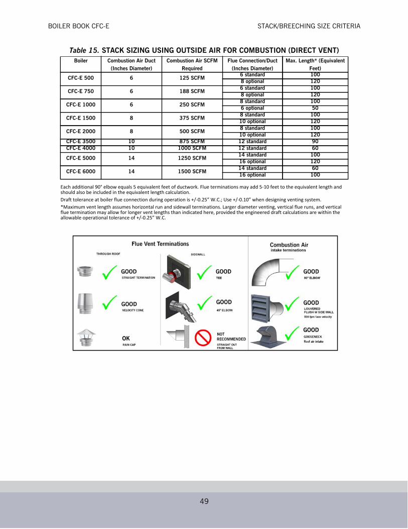
BOILER BOOK CFC-E STACK/BREECHING SIZE CRITERIA
49
Table 15. STACK SIZING USING OUTSIDE AIR FOR COMBUSTION (DIRECT VENT)Boiler Combustion Air Duct
(Inches Diameter)Combustion Air SCFM
RequiredFlue Connection/Duct
(Inches Diameter)Max. Length* (Equivalent
Feet)
CFC-E 500 6 125 SCFM6 standard 1008 optional 120
CFC-E 750 6 188 SCFM6 standard 1008 optional 120
CFC-E 1000 6 250 SCFM8 standard 1006 optional 50
CFC-E 1500 8 375 SCFM8 standard 10010 optional 120
CFC-E 2000 8 500 SCFM8 standard 10010 optional 120
CFC-E 3500 10 875 SCFM 12 standard 90CFC-E 4000 10 1000 SCFM 12 standard 60
CFC-E 5000 14 1250 SCFM14 standard 10016 optional 120
CFC-E 6000 14 1500 SCFM14 standard 6016 optional 100
Each additional 90° elbow equals 5 equivalent feet of ductwork. Flue terminations may add 5-10 feet to the equivalent length and should also be included in the equivalent length calculation.Draft tolerance at boiler flue connection during operation is +/-0.25” W.C.; Use +/-0.10” when designing venting system.*Maximum vent length assumes horizontal run and sidewall terminations. Larger diameter venting, vertical flue runs, and vertical flue termination may allow for longer vent lengths than indicated here, provided the engineered draft calculations are within the allowable operational tolerance of +/-0.25” W.C.

BOILER BOOK CFC-E STACK/BREECHING SIZE CRITERIA
50
Vertical Venting Inside Combustion Air
See Figure 34.
Figure 34. Inside Air - Vertical Vent
As noted in Paragraph A above, these installations use air from within the boiler room forcombustion. The same recommendations apply as noted in Paragraph A above.
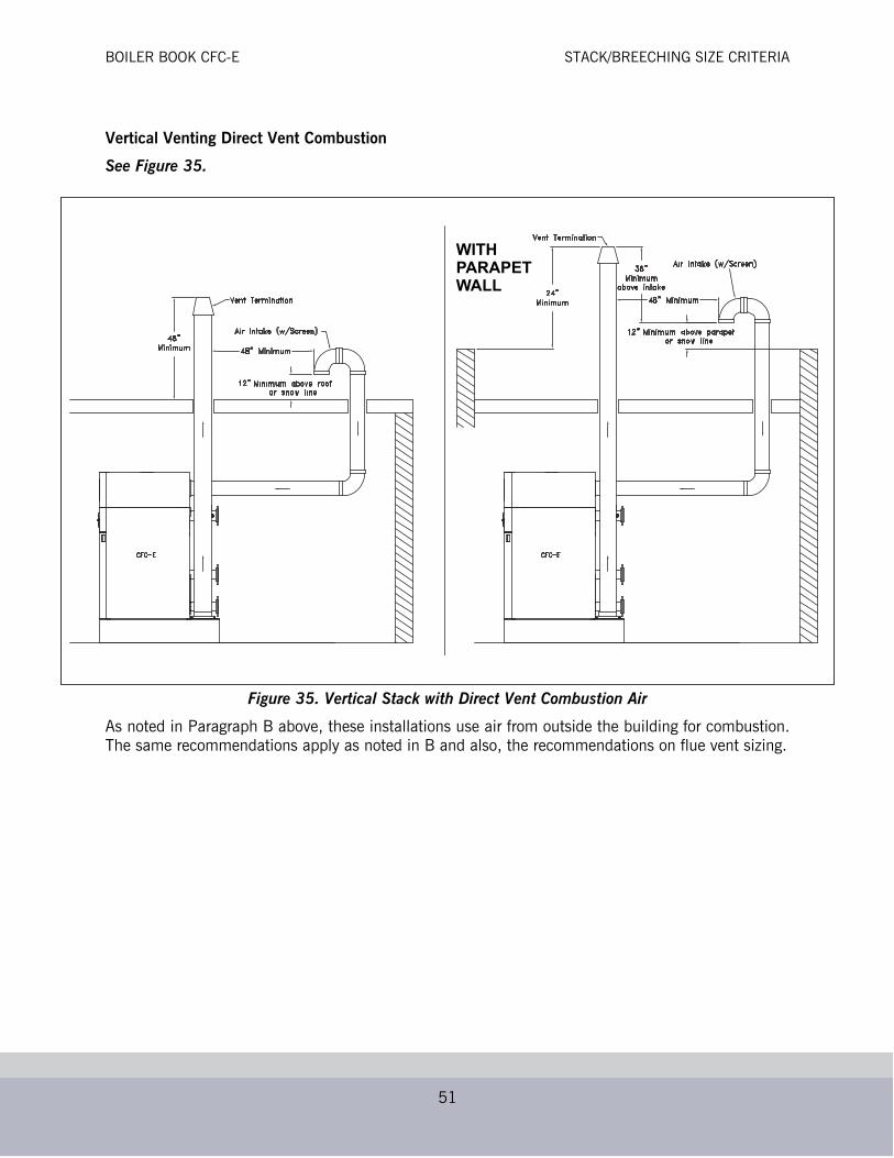
BOILER BOOK CFC-E STACK/BREECHING SIZE CRITERIA
51
Vertical Venting Direct Vent Combustion
See Figure 35.
Figure 35. Vertical Stack with Direct Vent Combustion Air
As noted in Paragraph B above, these installations use air from outside the building for combustion.The same recommendations apply as noted in B and also, the recommendations on flue vent sizing.
WITHPARAPETWALL

BOILER BOOK CFC-E STACK/BREECHING SIZE CRITERIA
52
Boiler Rear Connections
Figure 36. CFC-E Rear Connections
COMBUSTION
ELECTRICALRACEWAY
ELECTRICAL RACEWAY
HIGH TEMPERATURERETURN
LOW TEMPERATURERETURN
AIR INLET

BOILER BOOK CFC-E CB FALCON CONTROLLER
53
CB FALCON CONTROLLER1. Control Description - The CB Falcon hydronic control is an integrated burner management and
modulation control with a touch-screen display/operator interface.2. Functionality - The controller is capable of the following functions:
• Flame supervision• Burner sequencing• Heating/modulation control• Hot water system pump control• High Limit temperature control• Thermowell-mounted NTC temperature sensors to provide measured process variable signals to
the controller.• User-friendly touchscreen interface• Modbus communication capability• Alarm/lockout messaging with history (last 15 messages)• Annunciation• Outdoor reset• Central Heating and Domestic Hot Water loop control• Password protection of configurable parameters• High Stack Temperature limit• Remote reset• Lead/Lag sequencing• (3) configurable pump relays• Remote modulation/remote setpoint• Frost protection
• Time of Day (dual setpoint) control• Three levels of access to control configuration:
•End-user•Installer/Service Engineer (password protected)•OEM Manufacturer (password protected)
Table 16. Operating Conditions - Controller
Temperature RangeOperating -4 F to 150 F (-20 C to 66 C)
Storage -40 F to 150 F (-40 C to 66 C)
Humidity 85% max. relative humidity, non-condensing
Table 17. Operating Conditions - Display/Interface
Temperature RangeOperating 32 F to 122 F (0 C to 50 C)
Storage -40 F to 150 F (-40 C to 66 C)
Humidity 85% max. relative humidity
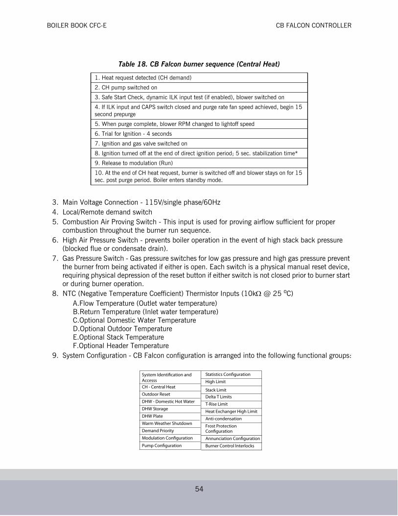
BOILER BOOK CFC-E CB FALCON CONTROLLER
54
3. Main Voltage Connection - 115V/single phase/60Hz4. Local/Remote demand switch5. Combustion Air Proving Switch - This input is used for proving airflow sufficient for proper
combustion throughout the burner run sequence.6. High Air Pressure Switch - prevents boiler operation in the event of high stack back pressure
(blocked flue or condensate drain).7. Gas Pressure Switch - Gas pressure switches for low gas pressure and high gas pressure prevent
the burner from being activated if either is open. Each switch is a physical manual reset device, requiring physical depression of the reset button if either switch is not closed prior to burner start or during burner operation.
8. NTC (Negative Temperature Coefficient) Thermistor Inputs (10k @ 25 oC)A.Flow Temperature (Outlet water temperature)B.Return Temperature (Inlet water temperature)C.Optional Domestic Water TemperatureD.Optional Outdoor TemperatureE.Optional Stack TemperatureF.Optional Header Temperature
9. System Configuration - CB Falcon configuration is arranged into the following functional groups:
Table 18. CB Falcon burner sequence (Central Heat)
1. Heat request detected (CH demand)
2. CH pump switched on
3. Safe Start Check, dynamic ILK input test (if enabled), blower switched on
4. If ILK input and CAPS switch closed and purge rate fan speed achieved, begin 15 second prepurge
5. When purge complete, blower RPM changed to lightoff speed
6. Trial for Ignition - 4 seconds
7. Ignition and gas valve switched on
8. Ignition turned off at the end of direct ignition period; 5 sec. stabilization time*
9. Release to modulation (Run)
10. At the end of CH heat request, burner is switched off and blower stays on for 15 sec. post purge period. Boiler enters standby mode.
System Identification andAccesss
CH - Central Heat
Outdoor Reset
DHW - Domestic Hot Water
DHW Storage
DHW Plate
Warm Weather Shutdown
Demand Priority
Modulation Configuration
Pump Configuration
Statistics Configuration
High Limit
Stack Limit
Delta T Limits
T-Rise Limit
Heat Exchanger High Limit
Anti-condensation
Frost Protection Configuration
Annunciation Configuration
Burner Control Interlocks

BOILER BOOK CFC-E CB FALCON CONTROLLER
55
10. CB Falcon Access - There are three levels of access to the CB Falcon controller:
• End User Level - read or view parameters; change setpoints. No password required.
• Installer/Service Level - read all parameters; enables changing of most parameters. This access level is used to configure the CB Falcon for a particular installation, and is password-protected.
• OEM Level - read/change all parameters; for factory configuration of boiler-specific parameters. Password-protected and restricted to CB or factory authorized service personnel.
For additional information regarding service and setup of the burner controller, refer to CFC-E manual750-263 or to the CB Falcon manual 750-265.
Figure 37. CB Falcon Pinout
3
1
4
2
FLAMESTRENGTH
LOCALMODBUSA B C
GLOBALMODBUSA B C
POWER
FLAME
ALARM
RESET
PIM
1
2
3
4
5
6
CB FALCONHYDRONICCONTROL
J1 J2J1
J3ENVIRACOM
D R C
L1
L2 FOR 120VAC OR 24VAC RETURN (OPTOS)
EGND
EX. IGNITION
ALARM
MAIN VALVE
ANNUN 1/IASANNUN 2
ANNUN 3ANNUN 4ANNUN 5ANNUN 6
INTERLOCK
P
P
P
LCI
PUMP A
{{
{PUMP B
PUMP C
24 VAC24 VAC RTN
INLET TEMPINLET TEMP RTN
HEADER TEMPHEADER TEMP RTN
OUTLET TEMP AOUTLET TEMP RTN
OUTLET TEMP BOUTDOOR TEMP
OUTDOOR TEMP RTN
DHW TEMP ADHW TEMP RTN
DHW TEMP BSTACK TEMP A
STACK TEMP RTNSTACK TEMP B
TODREMOTE RESET
AUX. (REMOTE) INPUT
0 - 10 VDC MA /VDC RTN
4 TO 20 MAV
I
BUILDINGAUTOMATION
SYSTEM
TACHOMETERPWM OUT
FAN POWER (25 VDC)FAN GND
MULTIPLEAPPLIANCE
CONTROLLER
GLOBALMODBUSLOCALMODBUS
++–
FUTURE
LOCAL DISPLAY
SYSTEM DISPLAY
J4
J5
J6
J7
J9
J8
J10
J11
121110 9 8 7 6 5 4 3 2 1
7654321
87654321
7654321
123456789
101112
1234567
12345678
1234567

BOILER BOOK CFC-E EXAMPLE SYSTEM SCHEMATICS
56
EXAMPLE SYSTEM SCHEMATICSTypical piping arrangements using the CFC-E are shown in the figures that follow.Note: These diagrams are generic and are not intended for use in a specific design without consultation with your local
Cleaver-Brooks sales representative

BOILER BOOK CFC-E EXAMPLE SYSTEM SCHEMATICS
57
Figure 38. Primary/Secondary, Single Boiler
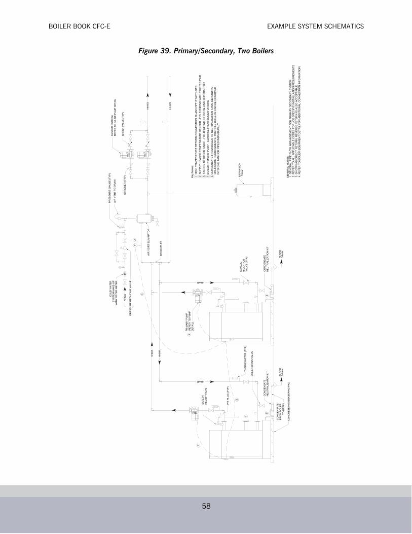
BOILER BOOK CFC-E EXAMPLE SYSTEM SCHEMATICS
58
Figure 39. Primary/Secondary, Two Boilers

BOILER BOOK CFC-E EXAMPLE SYSTEM SCHEMATICS
59
Figure 40. Primary/Secondary, Three Boilers

BOILER BOOK CFC-E EXAMPLE SYSTEM SCHEMATICS
60
Figure 41. Primary Variable Flow, Single Boiler

BOILER BOOK CFC-E EXAMPLE SYSTEM SCHEMATICS
61
Figure 42. Primary Variable Flow, Two Boilers
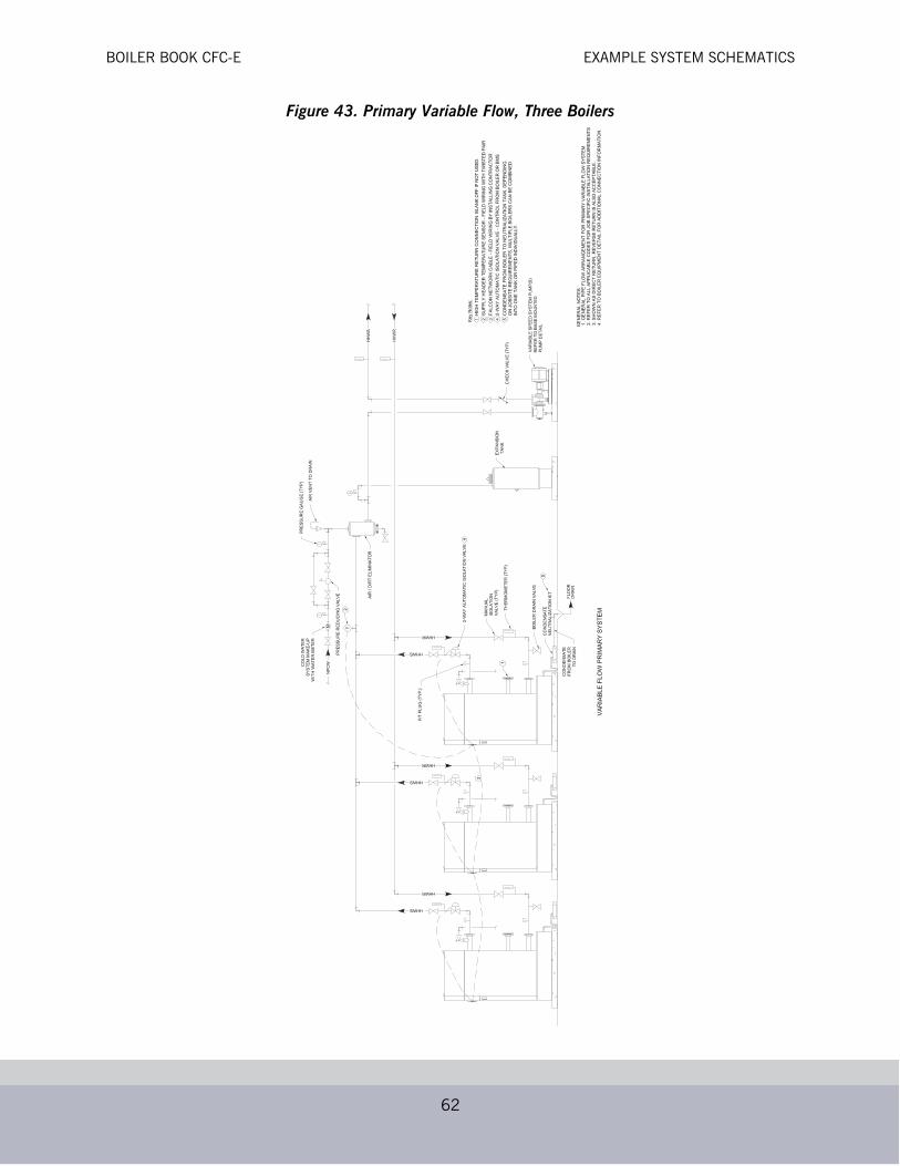
BOILER BOOK CFC-E EXAMPLE SYSTEM SCHEMATICS
62
Figure 43. Primary Variable Flow, Three Boilers

BOILER BOOK CFC-E EXAMPLE SYSTEM SCHEMATICS
63
Figure 44. Primary Variable Flow, Single Boiler with Heat Exchanger
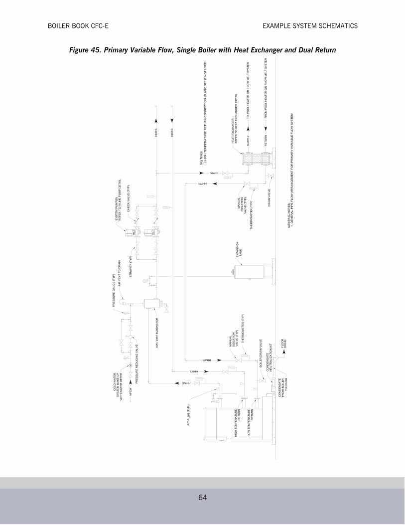
BOILER BOOK CFC-E EXAMPLE SYSTEM SCHEMATICS
64
Figure 45. Primary Variable Flow, Single Boiler with Heat Exchanger and Dual Return

BOILER BOOK CFC-E EXAMPLE SYSTEM SCHEMATICS
65
