cleaver-brooks criterion boilers model 4wg · cleaver-brooks equipment is designed and engineered...
TRANSCRIPT
Manual Part No. 750-212
2/05
CLEAVER-BROOKS
Criterion Boilers
Model 4WGOperation, Service, Maintenance and
Parts Manual100 to 800 HP
Steam and Hot Water
Fuel: Light Oil, Gas or Combination
Table Of Contents
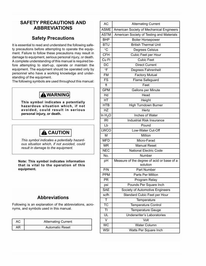
SAFETY PRECAUTIONS AND ABBREVIATIONS
Safety Precautions
It is essential to read and understand the following safe-
ty precautions before attempting to operate the equip-
ment. Failure to follow these precautions may result in
damage to equipment, serious personal injury, or death.
A complete understanding of this manual is required be-
fore attempting to start-up, operate or maintain the
equipment. The equipment should be operated only by
personnel who have a working knowledge and under-
standing of the equipment.
The following symbols are used throughout this manual:
! DANGERWARNING
This symbol indicates a potentiallyhazardous situation which, if notavoided, could resul t in ser iouspersonal injury, or death.
! DANGERCAUTION
This symbol indicates a potentially hazard-ous situation which, if not avoided, couldresult in damage to the equipment.
Note: This symbol indicates informationthat is vital to the operation of thisequipment.
Abbreviations
Following is an explanation of the abbreviations, acro-
nyms, and symbols used in this manual.
AC Alternating Current
AR Automatic Reset
ASME American Society of Mechanical Engineers
ASTM American Society of Testing and Materials
BHP Boiler Horsepower
BTU British Thermal Unit
°C Degrees Celsius
CFH Cubic Feet per Hour
Cu Ft Cubic Feet
DC Direct Current
°F Degrees Fahrenheit
FM Factory Mutual
FS Flame Safeguard
ft Feet
GPM Gallons per Minute
Hd Head
HT Height
HTB High Turndown Burner
HZ Hertz
In H2O Inches of Water
IRI Industrial Risk Insurance
Lb Pound
LWCO Low-Water Cut-Off
M Million
MFD Micro-Farad
MR Manual Reset
NEC National Electric Code
No. Number
pH Measure of the degree of acid or base of a
solution
P/N Part Number
PPM Parts Per Million
PR Program Relay
psi Pounds Per Square Inch
SAE Society of Automotive Engineers
scfh Standard Cubic Feet per Hour
T Temperature
TC Temperature Control
TI Temperature Gauge
UL Underwriter’s Laboratories
V Volt
WC Water Column
WSI Watts Per Square Inch
AC Alternating Current
Criterion Boilers
MODEL 4WG
Operation, Service, Maintenance and Parts Manual
100 to 800 Horse Power Steam and Hot WaterFuel: Light Oil, Gas or Combination
Please direct purchase orders for replacement manuals to your local Cleaver-Brooks authorized representative
Manual Part No. 750-212
Revised 2/05Printed in U.S.A.
© Cleaver-Brooks 2005

i
TO: Owners, Operators and/or Maintenance Personnel
This operating manual presents information that will help to properly operate and care for the equipment. Study its contentscarefully. The unit will provide good service and continued operation if proper operating and maintenance instructions are fol-lowed. No attempt should be made to operate the unit until the principles of operation and all of the components are thoroughlyunderstood. Failure to follow all applicable instructions and warnings may result in severe personal injury or death.
It is the responsibility of the owner to train and advise not only his or her personnel, but the contractors' personnel who are ser-vicing, repairing or operating the equipment, in all safety aspects.
Cleaver-Brooks equipment is designed and engineered to give long life and excellent service on the job. The electrical andmechanical devices supplied as part of the unit were chosen because of their known ability to perform; however, proper oper-ating techniques and maintenance procedures must be followed at all times. Although these components afford a high degreeof protection and safety, operation of equipment is not to be considered free from all dangers and hazards inherent in handlingand firing of fuel.
Any "automatic" features included in the design do not relieve the attendant of any responsibility. Such features merely freehim of certain repetitive chores and give him more time to devote to the proper upkeep of equipment.
It is solely the operator’s responsibility to properly operate and maintain the equipment. No amount of written instructions canreplace intelligent thinking and reasoning and this manual is not intended to relieve the operating personnel of the responsibilityfor proper operation. On the other hand, a thorough understanding of this manual is required before attempting to operate, main-tain, service, or repair this equipment.
Because of state, local, or other applicable codes, there are a variety of electric controls and safety devices which vary consid-erably from one boiler to another. This manual contains information designed to show how a basic burner operates.
Operating controls will normally function for long periods of time and we have found that some operators become lax in theirdaily or monthly testing, assuming that normal operation will continue indefinitely. Malfunctions of controls lead to uneco-nomical operation and damage and, in most cases, these conditions can be traced directly to carelessness and deficiencies intesting and maintenance.
It is recommended that a boiler room log or record be maintained. Recording of daily, weekly, monthly and yearly maintenanceactivities and recording of any unusual operation will serve as a valuable guide to any necessary investigation.
Most instances of major boiler damage are the result of operation with low water. We cannot emphasize too strongly the needfor the operator to periodically check his low water controls and to follow good maintenance and testing practices. Cross-con-necting piping to low water devices must be internally inspected periodically to guard against any stoppages which could ob-struct the free flow of water to the low water devices. Float bowls of these controls must be inspected frequently to check forthe presence of foreign substances that would impede float ball movement.
The waterside condition of the pressure vessel is of extreme importance. Waterside surfaces should be inspected frequently tocheck for the presence of any mud, sludge, scale or corrosion.
The services of a qualified water treating company or a water consultant to recommend the proper boiler water treating practicesare essential.
The operation of this equipment by the owner and his or her operating personnel must comply with all requirements or regula-tions of his insurance company and/or other authority having jurisdiction. In the event of any conflict or inconsistency betweensuch requirements and the warnings or instructions contained herein, please contact Cleaver-Brooks before proceeding.
DO NOT OPERATE, SERVICE, OR REPAIR THIS EQUIPMENT UNLESS YOU FULLY UNDERSTAND ALLAPPLICABLE SECTIONS OF THIS MANUAL.
DO NOT ALLOW OTHERS TO OPERATE, SERVICE, OR REPAIR THIS EQUIPMENT UNLESS THEY FULLYUNDERSTAND ALL APPLICABLE SECTIONS OF THIS MANUAL.
FAILURE TO FOLLOW ALL APPLICABLE WARNINGS AND INSTRUCTIONS MAY RESULT IN SEVEREPERSONAL INJURY OR DEATH.
! DANGERWARNING
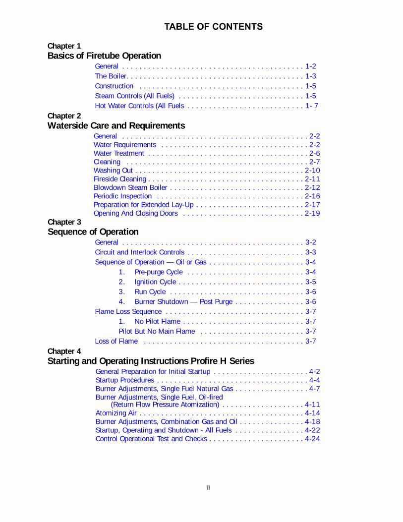
TABLE OF CONTENTS
Chapter 1Basics of Firetube Operation
General . . . . . . . . . . . . . . . . . . . . . . . . . . . . . . . . . . . . . . . . . . 1-2The Boiler. . . . . . . . . . . . . . . . . . . . . . . . . . . . . . . . . . . . . . . . . 1-3Construction . . . . . . . . . . . . . . . . . . . . . . . . . . . . . . . . . . . . . . 1-5Steam Controls (All Fuels) . . . . . . . . . . . . . . . . . . . . . . . . . . . . . 1-5Hot Water Controls (All Fuels . . . . . . . . . . . . . . . . . . . . . . . . . . . 1- 7
Chapter 2Waterside Care and Requirements
General . . . . . . . . . . . . . . . . . . . . . . . . . . . . . . . . . . . . . . . . . . . 2-2Water Requirements . . . . . . . . . . . . . . . . . . . . . . . . . . . . . . . . . . 2-2Water Treatment . . . . . . . . . . . . . . . . . . . . . . . . . . . . . . . . . . . . . 2-6Cleaning . . . . . . . . . . . . . . . . . . . . . . . . . . . . . . . . . . . . . . . . . . 2-7Washing Out . . . . . . . . . . . . . . . . . . . . . . . . . . . . . . . . . . . . . . . 2-10Fireside Cleaning . . . . . . . . . . . . . . . . . . . . . . . . . . . . . . . . . . . . 2-11Blowdown Steam Boiler . . . . . . . . . . . . . . . . . . . . . . . . . . . . . . . 2-12Periodic Inspection . . . . . . . . . . . . . . . . . . . . . . . . . . . . . . . . . . 2-16Preparation for Extended Lay-Up . . . . . . . . . . . . . . . . . . . . . . . . . 2-17Opening And Closing Doors . . . . . . . . . . . . . . . . . . . . . . . . . . . . 2-19
Chapter 3Sequence of Operation
General . . . . . . . . . . . . . . . . . . . . . . . . . . . . . . . . . . . . . . . . . . 3-2Circuit and Interlock Controls . . . . . . . . . . . . . . . . . . . . . . . . . . . 3-3Sequence of Operation — Oil or Gas . . . . . . . . . . . . . . . . . . . . . . 3-4
1. Pre-purge Cycle . . . . . . . . . . . . . . . . . . . . . . . . . . . 3-42. Ignition Cycle . . . . . . . . . . . . . . . . . . . . . . . . . . . . . 3-53. Run Cycle . . . . . . . . . . . . . . . . . . . . . . . . . . . . . . . 3-64. Burner Shutdown — Post Purge . . . . . . . . . . . . . . . . 3-6
Flame Loss Sequence . . . . . . . . . . . . . . . . . . . . . . . . . . . . . . . . 3-71. No Pilot Flame . . . . . . . . . . . . . . . . . . . . . . . . . . . . 3-7Pilot But No Main Flame . . . . . . . . . . . . . . . . . . . . . . . . 3-7
Loss of Flame . . . . . . . . . . . . . . . . . . . . . . . . . . . . . . . . . . . . . 3-7Chapter 4Starting and Operating Instructions Profire H Series
General Preparation for Initial Startup . . . . . . . . . . . . . . . . . . . . . . 4-2Startup Procedures . . . . . . . . . . . . . . . . . . . . . . . . . . . . . . . . . . . 4-4Burner Adjustments, Single Fuel Natural Gas . . . . . . . . . . . . . . . . . 4-7Burner Adjustments, Single Fuel, Oil-fired
(Return Flow Pressure Atomization) . . . . . . . . . . . . . . . . . . . 4-11Atomizing Air . . . . . . . . . . . . . . . . . . . . . . . . . . . . . . . . . . . . . . 4-14Burner Adjustments, Combination Gas and Oil . . . . . . . . . . . . . . . 4-18Startup, Operating and Shutdown - All Fuels . . . . . . . . . . . . . . . . 4-22Control Operational Test and Checks . . . . . . . . . . . . . . . . . . . . . . 4-24
ii
Chapter 5Profire D Series Burner
Description . . . . . . . . . . . . . . . . . . . . . . . . . . . . . . . . . . . . . . . .5-2Operating Controls / Control Panel . . . . . . . . . . . . . . . . . . . . . . . .5-2Flame Safety Controls (see Figure 5-3) . . . . . . . . . . . . . . . . . . . .5-3Combustion Air Handling System . . . . . . . . . . . . . . . . . . . . . . . .5-3Firing Rate Controls . . . . . . . . . . . . . . . . . . . . . . . . . . . . . . . . . .5-6Firing Head . . . . . . . . . . . . . . . . . . . . . . . . . . . . . . . . . . . . . . . .5-6Oil System Air Atomizing . . . . . . . . . . . . . . . . . . . . . . . . . . . . . .5-6Gas System . . . . . . . . . . . . . . . . . . . . . . . . . . . . . . . . . . . . . . .5-12Operation . . . . . . . . . . . . . . . . . . . . . . . . . . . . . . . . . . . . . . . . .5-14Gas System . . . . . . . . . . . . . . . . . . . . . . . . . . . . . . . . . . . . . . .5-16Oil System . . . . . . . . . . . . . . . . . . . . . . . . . . . . . . . . . . . . . . . .5-18Manual Shutdown . . . . . . . . . . . . . . . . . . . . . . . . . . . . . . . . . . .5-20Safety Shutdown . . . . . . . . . . . . . . . . . . . . . . . . . . . . . . . . . . . .5-20
Chapter 6ProFire D Series Burner Maintenance
Maintenance . . . . . . . . . . . . . . . . . . . . . . . . . . . . . . . . . . . . . . .6-2General . . . . . . . . . . . . . . . . . . . . . . . . . . . . . . . . . . . . . . . . . . .6-2Control System . . . . . . . . . . . . . . . . . . . . . . . . . . . . . . . . . . . . .6-2Firing Head Inspection . . . . . . . . . . . . . . . . . . . . . . . . . . . . . . . .6-4Pilot And Ignition Electrode . . . . . . . . . . . . . . . . . . . . . . . . . . . . .6-4Oil Nozzle. . . . . . . . . . . . . . . . . . . . . . . . . . . . . . . . . . . . . . . . .6-4Diffuser . . . . . . . . . . . . . . . . . . . . . . . . . . . . . . . . . . . . . . . . . . .6-5Firing Rate Controls . . . . . . . . . . . . . . . . . . . . . . . . . . . . . . . . . .6-6Gas System . . . . . . . . . . . . . . . . . . . . . . . . . . . . . . . . . . . . . . .6-10Electrical System . . . . . . . . . . . . . . . . . . . . . . . . . . . . . . . . . . . .6-10Extended Shutdown . . . . . . . . . . . . . . . . . . . . . . . . . . . . . . . . . .6-11Troubleshooting . . . . . . . . . . . . . . . . . . . . . . . . . . . . . . . . . . . . .6-11Emergency Shut Down . . . . . . . . . . . . . . . . . . . . . . . . . . . . . . . .6-12
Chapter 7Troubleshooting
Burner Does Not Start . . . . . . . . . . . . . . . . . . . . . . . . . . . . . . . . 7-3No Ignition . . . . . . . . . . . . . . . . . . . . . . . . . . . . . . . . . . . . . . . . 7-3Pilot Flame, But No Main Flame . . . . . . . . . . . . . . . . . . . . . . . . . 7-4Burner Stays in Low Fire . . . . . . . . . . . . . . . . . . . . . . . . . . . . . . 7-4Shutdown Occurs During Firing . . . . . . . . . . . . . . . . . . . . . . . . . . 7-4Modulating Motor Does Not Operate . . . . . . . . . . . . . . . . . . . . . . 7-5
iii

Chapter 8Parts
FRONT DOOR & SMOKEBOX, 60"-85", 100-400 HP - - - - - - - - - - - - - - - - - - - - - - - - - - - 8-2FRONT DOOR & SMOKEBOX, 60"-85", 100-400 HP - - - - - - - - - - - - - - - - - - - - - - - - - - - 8-3FRONT DOOR & SMOKEBOX, 96"-106", 500-800 HP - - - - - - - - - - - - - - - - - - - - - - - - - - 8-4FRONT DOOR & SMOKEBOX, 96"-106", 500-800 HP - - - - - - - - - - - - - - - - - - - - - - - - - - 8-5REAR DOOR INSULATED ASSEMBLY - - - - - - - - - - - - - - - - - - - - - - - - - - - - - - - - - - - - - 8-6REAR DOOR INSULATION COMPONENT LIST - - - - - - - - - - - - - - - - - - - - - - - - - - - - - - - 8-7REAR DOOR INSULATED ACCESS PLUG - - - - - - - - - - - - - - - - - - - - - - - - - - - - - - - - - - - 8-8REAR DOOR DAVIT PARTS LIST - - - - - - - - - - - - - - - - - - - - - - - - - - - - - - - - - - - - - - - - 8-9BURNER SELECTION/INSTALLATION 60"-106" 100-800 HP - - - - - - - - - - - - - - - - - - - - - 8-10WATER COLUMN PIPING, 60"-67", 100-200 HP - - - - - - - - - - - - - - - - - - - - - - - - - - - - - 8-12WATER COLUMN PIPING, 60"-67", 100-200 HP - - - - - - - - - - - - - - - - - - - - - - - - - - - - - 8-13WATER COLUMN PIPING, 78"-85", 250-400 HP - - - - - - - - - - - - - - - - - - - - - - - - - - - - - 8-14WATER COLUMN PIPING, 78"-85", 250-400 HP - - - - - - - - - - - - - - - - - - - - - - - - - - - - - 8-15WATER COLUMN PIPING, 96"-106", 500-800 HP - - - - - - - - - - - - - - - - - - - - - - - - - - - - 8-16WATER COLUMN PIPING, 96"-106", 500-800 HP - - - - - - - - - - - - - - - - - - - - - - - - - - - - 8-17STEAM PRESSURE CONTROLS, 60"-106", 100-800 HP - - - - - - - - - - - - - - - - - - - - - - - - 8-18HOT WATER TEMPERATURE CONTROLS, 60"-106", 100-800 HP - - - - - - - - - - - - - - - - - 8-19MAIN GAS TRAIN, 60"-106" 100-800 HP STANDARD, FM, IRI, & F&I INSURANCES - - - - 8-20PILOT GAS TRAIN, 60"-106" 100-800 HP STANDARD, FM, IRI, & F&I INSURANCES - - - - 8-21AIR OIL PIPING 60”-78” 100-300HP - - - - - - - - - - - - - - - - - - - - - - - - - - - - - - - - - - - - - 8-22AIR COMPRESSOR PIPING 85” - 106” 350-800 HP - - - - - - - - - - - - - - - - - - - - - - - - - - 8-23AIR COMPRESSOR ASSEMBLY P/N 615-00023, 60-78", 100-300 HP - - - - - - - - - - - - - - 8-24Air Compressor Piping 55” - 96” - - - - - - - - - - - - - - - - - - - - - - - - - - - - - - - - - - - - - - - - 8-25FGR PIPING, 60"-106" 100-800 HP - - - - - - - - - - - - - - - - - - - - - - - - - - - - - - - - - - - - - 8-2660”-106”, 100-800 HP FEEDWATER PIPING W/3 VALVE BYPASS - - - - - - - - - - - - - - - - - 8-2760”-106”, 100-800 HP SURFACE BLOWOFF W/ & W/O HYDAC AND SAMPLE COOLER - - 8-2860” 106”, 100-800 HP SURFACE BLOWOFF W/ & W/O HYDAC AND SAMPLE COOLER - - 8-29

Notes:

Chapter 1
Basics of Firetube Operation
A. General 1-2
B. The Boiler 1-3
C. Construction 1-5
D. Steam Controls (All Fuels) 1-5
E. Hot Water Controls (All Fuels) 1-7
Table of Contents
Milwaukee, Wisconsin
www.cleaver-brooks.com
Criterion Boiler Cutaway, Wet-Back Design . . . . . . . . . . . . . . . . . .1-2
Criterion 4WG Firetube Boiler . . . . . . . . . . . . . . . . . . . . . . . . . . . . .1-2
Criterion 4WG Rear Access Way with Rear Door Open . . . . . . . . .1-2
Criterion 4 Pass Wet-Back Design . . . . . . . . . . . . . . . . . . . . . . . . . .1-3
Access Way to Second Pass Turnaround Chamber . . . . . . . . . . . .1-3
Front Baffle Between 3rd and 4th Gas Pass . . . . . . . . . . . . . . . . . .1-4
Deaerator in Feedwater System . . . . . . . . . . . . . . . . . . . . . . . . . . .1-4
ASME Welding on Firetube Boiler . . . . . . . . . . . . . . . . . . . . . . . . . .1-5
Pressure Controls. . . . . . . . . . . . . . . . . . . . . . . . . . . . . . . . . . . . . . .1-5
Water Column and Level Master Low Water Cut-Off . . . . . . . . . . .1-6
Auxiliary Low Water Cutoff . . . . . . . . . . . . . . . . . . . . . . . . . . . . . . .1-6
Safety Valves . . . . . . . . . . . . . . . . . . . . . . . . . . . . . . . . . . . . . . . . . .1-7
Hot Water Controls. . . . . . . . . . . . . . . . . . . . . . . . . . . . . . . . . . . . . .1-7
LWCO Probe Type . . . . . . . . . . . . . . . . . . . . . . . . . . . . . . . . . . . . . .1-7
Safety Valves Check . . . . . . . . . . . . . . . . . . . . . . . . . . . . . . . . . . . .1-7
List of Figures
Chapter 1 — Basics of Firetube Operation
A. General
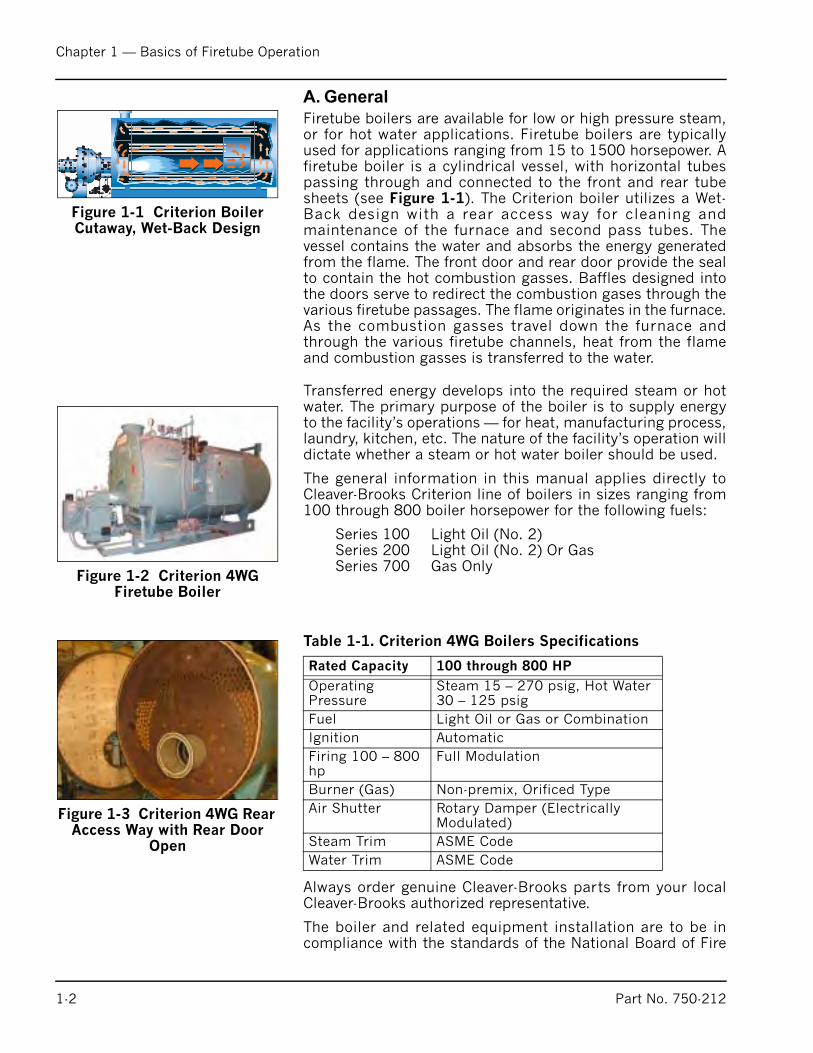
Firetube boilers are available for low or high pressure steam,or for hot water applications. Firetube boilers are typicallyused for applications ranging from 15 to 1500 horsepower. Afiretube boiler is a cylindrical vessel, with horizontal tubespassing through and connected to the front and rear tubesheets (see Figure 1-1). The Criterion boiler utilizes a Wet-Back design with a rear access way for cleaning andmaintenance of the furnace and second pass tubes. Thevessel contains the water and absorbs the energy generatedfrom the flame. The front door and rear door provide the sealto contain the hot combustion gasses. Baffles designed intothe doors serve to redirect the combustion gases through thevarious firetube passages. The flame originates in the furnace.As the combustion gasses travel down the furnace andthrough the various firetube channels, heat from the flameand combustion gasses is transferred to the water.
Transferred energy develops into the required steam or hotwater. The primary purpose of the boiler is to supply energyto the facility’s operations — for heat, manufacturing process,laundry, kitchen, etc. The nature of the facility’s operation willdictate whether a steam or hot water boiler should be used.
The general information in this manual applies directly toCleaver-Brooks Criterion line of boilers in sizes ranging from100 through 800 boiler horsepower for the following fuels:
Series 100 Light Oil (No. 2)Series 200 Light Oil (No. 2) Or GasSeries 700 Gas Only
Always order genuine Cleaver-Brooks parts from your localCleaver-Brooks authorized representative.
The boiler and related equipment installation are to be incompliance with the standards of the National Board of Fire
Figure 1-1 Criterion Boiler Cutaway, Wet-Back Design
Figure 1-2 Criterion 4WG Firetube Boiler
Figure 1-3 Criterion 4WG Rear Access Way with Rear Door
Open
Table 1-1. Criterion 4WG Boilers Specifications
Rated Capacity 100 through 800 HP
Operating Pressure
Steam 15 – 270 psig, Hot Water 30 – 125 psig
Fuel Light Oil or Gas or Combination
Ignition Automatic
Firing 100 – 800 hp
Full Modulation
Burner (Gas) Non-premix, Orificed Type
Air Shutter Rotary Damper (Electrically Modulated)
Steam Trim ASME Code
Water Trim ASME Code
1-2 Part No. 750-212
Chapter 1 — Basics of Firetube Operation
Underwriters. Installation should also conform to state andlocal codes governing such equipment. Prior to installation,the proper authorities having jurisdiction are to be consulted,permits obtained, etc. All boilers in the Criterion seriescomply, when equipped with optional equipment, to IndustrialRisk Insurers (IRI), Factory Mutual (FM), or other insuringunderwriters requirements.
B. The Boiler
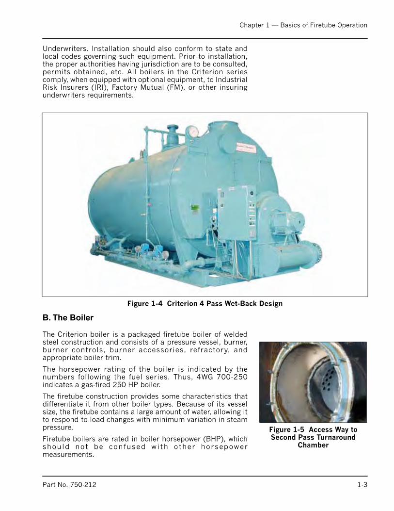
The Criterion boiler is a packaged firetube boiler of weldedsteel construction and consists of a pressure vessel, burner,burner controls, burner accessories, refractory, andappropriate boiler trim.
The horsepower rating of the boiler is indicated by thenumbers following the fuel series. Thus, 4WG 700-250indicates a gas-fired 250 HP boiler.
The firetube construction provides some characteristics thatdifferentiate it from other boiler types. Because of its vesselsize, the firetube contains a large amount of water, allowing itto respond to load changes with minimum variation in steampressure.
Firetube boilers are rated in boiler horsepower (BHP), whichshould not be confused wi th other horsepowermeasurements.
Figure 1-4 Criterion 4 Pass Wet-Back Design
Figure 1-5 Access Way to Second Pass Turnaround
Chamber
Part No. 750-212 1-3
Chapter 1 — Basics of Firetube Operation
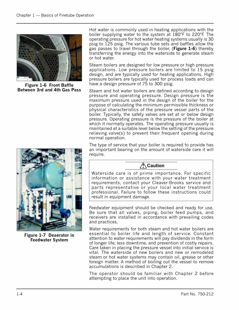
Hot water is commonly used in heating applications with theboiler supplying water to the system at 180°F to 220°F. Theoperating pressure for hot water heating systems usually is 30psig to 125 psig. The various tube sets and baffles allow thegas passes to travel through the boiler, (Figure 1-6) therebytransferring the energy into the waterside to generate steamor hot water.
Steam boilers are designed for low pressure or high pressureapplications. Low pressure boilers are limited to 15 psigdesign, and are typically used for heating applications. Highpressure boilers are typically used for process loads and canhave a design pressure of 75 to 300 psig.
Steam and hot water boilers are defined according to designpressure and operating pressure. Design pressure is themaximum pressure used in the design of the boiler for thepurpose of calculating the minimum permissible thickness orphysical characteristics of the pressure vessel parts of theboiler. Typically, the safety valves are set at or below designpressure. Operating pressure is the pressure of the boiler atwhich it normally operates. The operating pressure usually ismaintained at a suitable level below the setting of the pressurerelieving valve(s) to prevent their frequent opening duringnormal operation.
The type of service that your boiler is required to provide hasan important bearing on the amount of waterside care it willrequire.
Feedwater equipment should be checked and ready for use.Be sure that all valves, piping, boiler feed pumps, andreceivers are installed in accordance with prevailing codesand practices.
Water requirements for both steam and hot water boilers areessential to boiler life and length of service. Constantattention to water requirements will pay dividends in the formof longer life, less downtime, and prevention of costly repairs.Care taken in placing the pressure vessel into initial service isvital. The waterside of new boilers and new or remodeledsteam or hot water systems may contain oil, grease or otherforeign matter. A method of boiling out the vessel to removeaccumulations is described in Chapter 2.
The operator should be familiar with Chapter 2 beforeattempting to place the unit into operation.
Figure 1-6 Front Baffle Between 3rd and 4th Gas Pass
Figure 1-7 Deaerator in Feedwater System
! Caution
Waterside care is of prime importance. For specificinformation or assistance with your water treatmentrequirements, contact your Cleaver-Brooks service andparts representative or your local water treatmentprofessional. Failure to follow these instructions couldresult in equipment damage.
1-4 Part No. 750-212
Chapter 1 — Basics of Firetube Operation
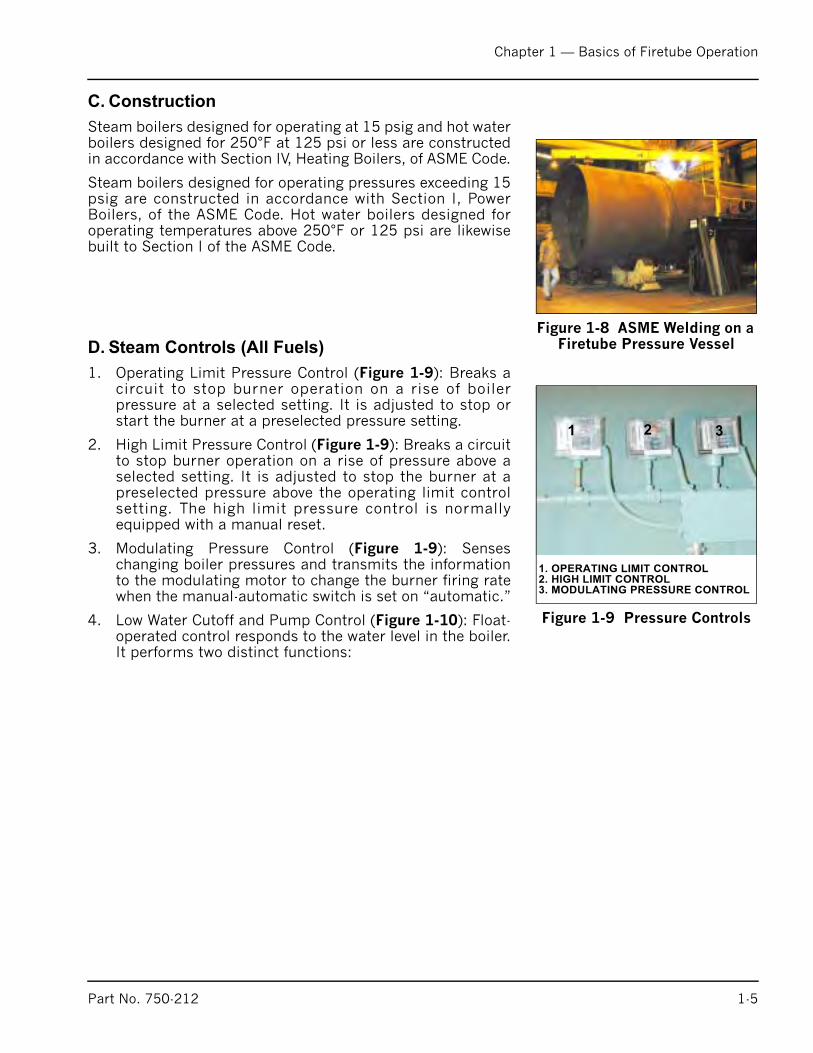
C. Construction
Steam boilers designed for operating at 15 psig and hot waterboilers designed for 250°F at 125 psi or less are constructedin accordance with Section IV, Heating Boilers, of ASME Code.
Steam boilers designed for operating pressures exceeding 15psig are constructed in accordance with Section I, PowerBoilers, of the ASME Code. Hot water boilers designed foroperating temperatures above 250°F or 125 psi are likewisebuilt to Section I of the ASME Code.
D. Steam Controls (All Fuels)
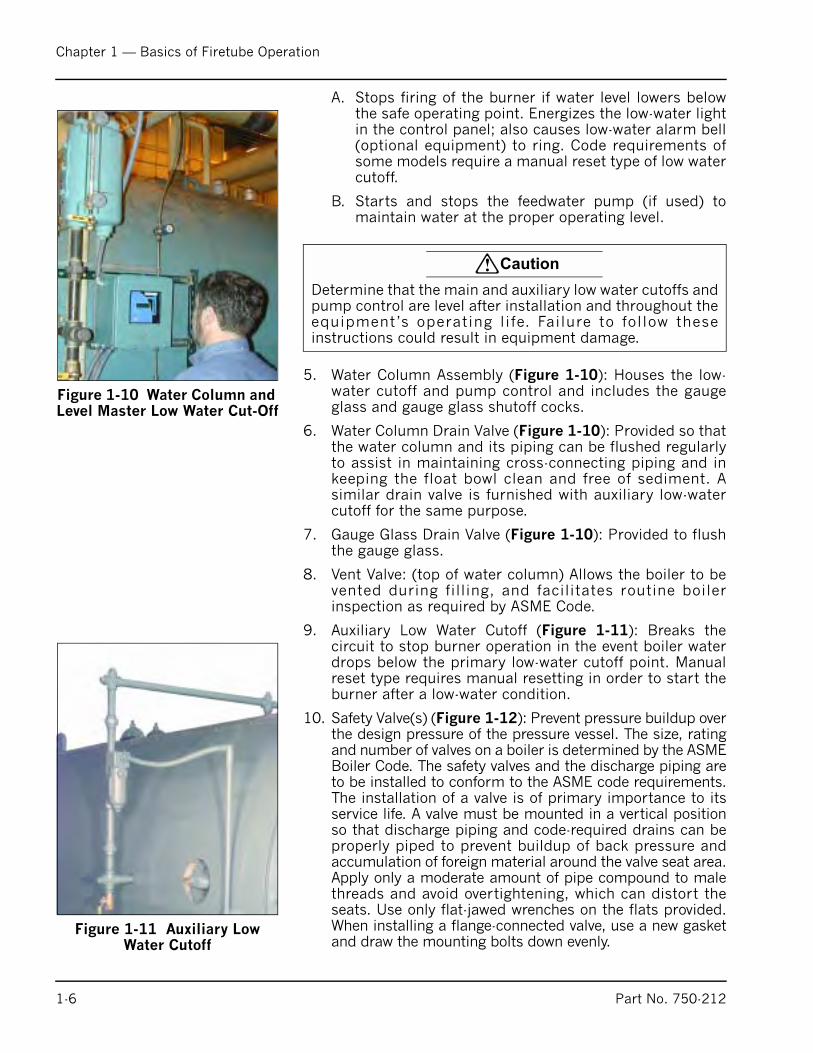
1. Operating Limit Pressure Control (Figure 1-9): Breaks acircuit to stop burner operation on a rise of boilerpressure at a selected setting. It is adjusted to stop orstart the burner at a preselected pressure setting.
2. High Limit Pressure Control (Figure 1-9): Breaks a circuitto stop burner operation on a rise of pressure above aselected setting. It is adjusted to stop the burner at apreselected pressure above the operating limit controlsetting. The high limit pressure control is normallyequipped with a manual reset.
3. Modulating Pressure Control (Figure 1-9): Senseschanging boiler pressures and transmits the informationto the modulating motor to change the burner firing ratewhen the manual-automatic switch is set on “automatic.”
4. Low Water Cutoff and Pump Control (Figure 1-10): Float-operated control responds to the water level in the boiler.It performs two distinct functions:
Figure 1-8 ASME Welding on a Firetube Pressure Vessel
Figure 1-9 Pressure Controls
1 2 3
1. OPERATING LIMIT CONTROL
2. HIGH LIMIT CONTROL
3. MODULATING PRESSURE CONTROL
Part No. 750-212 1-5
Chapter 1 — Basics of Firetube Operation
A. Stops firing of the burner if water level lowers belowthe safe operating point. Energizes the low-water lightin the control panel; also causes low-water alarm bell(optional equipment) to ring. Code requirements ofsome models require a manual reset type of low watercutoff.
B. Starts and stops the feedwater pump (if used) tomaintain water at the proper operating level.
5. Water Column Assembly (Figure 1-10): Houses the low-water cutoff and pump control and includes the gaugeglass and gauge glass shutoff cocks.
6. Water Column Drain Valve (Figure 1-10): Provided so thatthe water column and its piping can be flushed regularlyto assist in maintaining cross-connecting piping and inkeeping the float bowl clean and free of sediment. Asimilar drain valve is furnished with auxiliary low-watercutoff for the same purpose.
7. Gauge Glass Drain Valve (Figure 1-10): Provided to flushthe gauge glass.
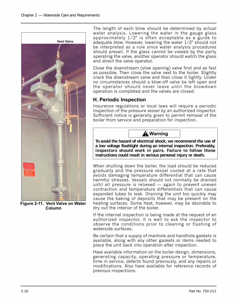
8. Vent Valve: (top of water column) Allows the boiler to bevented during filling, and facilitates routine boilerinspection as required by ASME Code.
9. Auxiliary Low Water Cutoff (Figure 1-11): Breaks thecircuit to stop burner operation in the event boiler waterdrops below the primary low-water cutoff point. Manualreset type requires manual resetting in order to start theburner after a low-water condition.
10. Safety Valve(s) (Figure 1-12): Prevent pressure buildup overthe design pressure of the pressure vessel. The size, ratingand number of valves on a boiler is determined by the ASMEBoiler Code. The safety valves and the discharge piping areto be installed to conform to the ASME code requirements.The installation of a valve is of primary importance to itsservice life. A valve must be mounted in a vertical positionso that discharge piping and code-required drains can beproperly piped to prevent buildup of back pressure andaccumulation of foreign material around the valve seat area.Apply only a moderate amount of pipe compound to malethreads and avoid overtightening, which can distort theseats. Use only flat-jawed wrenches on the flats provided.When installing a flange-connected valve, use a new gasketand draw the mounting bolts down evenly.
Figure 1-10 Water Column and Level Master Low Water Cut-Off
! Caution
Determine that the main and auxiliary low water cutoffs andpump control are level after installation and throughout theequipment’s operating life. Failure to follow theseinstructions could result in equipment damage.
Figure 1-11 Auxiliary Low Water Cutoff
1-6 Part No. 750-212

Chapter 1 — Basics of Firetube Operation
E. Hot Water Controls (All Fuels)
1. Water Temperature Gauge (Figure 1-13): Indicates the boiler internal water pressure.
2. Operating Limit Temperature Control (Figure 1-13):Breaks a circuit to stop burner operation on a rise ofboiler temperature at a selected setting. It is adjusted tostop or start the burner at a preselected operatingtemperature.
3. High Limit Temperature Control (Figure 1-13): Breaks acircuit to stop burner operation on a rise of temperatureat a selected setting. It is adjusted to stop burner at apreselected temperature above the operating controlsetting. The high limit temperature control normally isequipped with a manual reset.
4. Low Water Cutoff (Figure 1-14) (Optional probe type):Breaks the circuit to stop burner operation if the waterlevel in the boiler drops below the primary low-watercutoff point.
Safety Valve(s) (Figure 1-15): Relieves the boiler of pressurehigher than the design pressure or a lower pressure, ifdesignated. Relief valves and their discharge piping are to beinstalled to conform to ASME Code requirements.
Figure 1-12 Safety Valves
! Warning
Only properly certified personnel such as the safety valvemanufacturer’s certified representative can adjust or repairthe boiler safety valves. Failure to follow these instructionscould result in serious personal injury or death.
Figure 1-13 Hot Water Temperature Controls
Figure 1-14 LWCO Probe Type! Warning
Only properly certified personnel such as the relief valvemanufacturer’s certified representative can adjust or repairthe boiler relief valves. Failure to follow these instructionscould result in serious personal injury or death.
Part No. 750-212 1-7

Chapter 1 — Basics of Firetube Operation
1-8 Part No. 750-212
Notes:
Milwaukee, Wisconsin
www.cleaver-brooks.com
Chapter 2
Waterside Care and Requirements
Table of Contents
General . . . . . . . . . . . . . . . . . . . . . . . . . . . . . . . . . . . . . . . . . . . . . 2-2Water Requirements . . . . . . . . . . . . . . . . . . . . . . . . . . . . . . . . . . . . 2-2Water Treatment. . . . . . . . . . . . . . . . . . . . . . . . . . . . . . . . . . . . . . . . 2-6Cleaning . . . . . . . . . . . . . . . . . . . . . . . . . . . . . . . . . . . . . . . . . . . . . 2-7Washing Out . . . . . . . . . . . . . . . . . . . . . . . . . . . . . . . . . . . . . . . . . 2-10Fireside Cleaning . . . . . . . . . . . . . . . . . . . . . . . . . . . . . . . . . . . . . . 2-11Blowdown Steam Boiler . . . . . . . . . . . . . . . . . . . . . . . . . . . . . . . . . 2-12Periodic Inspection . . . . . . . . . . . . . . . . . . . . . . . . . . . . . . . . . . . . 2-16Preparation for Extended Lay-Up . . . . . . . . . . . . . . . . . . . . . . . . . . . 2-17Opening And Closing Doors . . . . . . . . . . . . . . . . . . . . . . . . . . . . . . 2-19
Water Column . . . . . . . . . . . . . . . . . . . . . . . . . . . . . . . . . . . . . . . . . 2-2Dip Tube . . . . . . . . . . . . . . . . . . . . . . . . . . . . . . . . . . . . . . . . . . . . 2-2Water Level Gauge Glass . . . . . . . . . . . . . . . . . . . . . . . . . . . . . . . . . 2-4Low-Water Cutoff Auxiliary Low Water Cutoff and High Water Cutoff . . . 2-5Low Water Cut Off . . . . . . . . . . . . . . . . . . . . . . . . . . . . . . . . . . . . . . 2-6Bottom Blowdown Valves . . . . . . . . . . . . . . . . . . . . . . . . . . . . . . . . 2-10Bottom Blowdown Layout . . . . . . . . . . . . . . . . . . . . . . . . . . . . . . . . 2-11Blowing Down the Water Column . . . . . . . . . . . . . . . . . . . . . . . . . . 2-13Vent Valve on Water Column . . . . . . . . . . . . . . . . . . . . . . . . . . . . . . 2-14
List of Figures
Chapter 2 — Waterside Care and Requirements
A. General
The operator should be familiar with this entire manual andrelated equipment Operation and Service manuals beforeattempting to place the unit into operation.
Although it is of prime importance, the subject of watersupply and treatment cannot adequately be covered in thismanual. For specific information or assistance with yourwater treatment requirements, contact your Cleaver-Brooksservice and parts representative.
Feedwater equipment should be checked and ready for use.Be sure that all valves, piping, boiler feed pumps, andreceivers are installed in accordance with prevailing codesand practices.
Water requirements for both steam and hot water boilers areessential to boiler life and length of service. It is vital thatcare be taken in placing the pressure vessel into initialservice. The waterside of new boilers and new or remodeledsteam or hot water systems may contain oil, grease or otherforeign matter. A method of boiling out the vessel to removethe accumulations is described later in Chapter 2.
Boilers, as a part of a hot water system, require proper watercirculation. The system must be operated as intended by itsdesigner in order to avoid thermal shock or severe, possiblydamaging, stresses from occurring to the pressure vessel.
Note: This manual only covers boilers using water. Glycolsolutions have different operating requirements,circulation rates and temperatures, etc.
B. Water Requirements
1. Hot Water Boiler
Air Removal
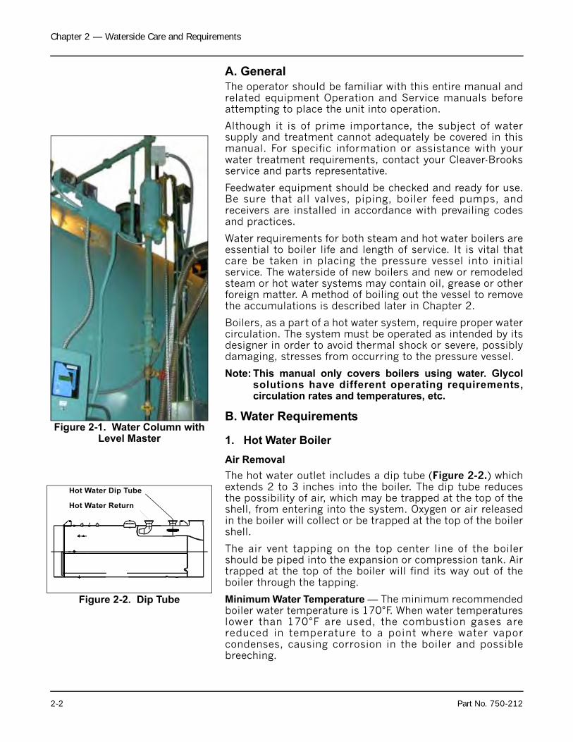
The hot water outlet includes a dip tube (Figure 2-2.) whichextends 2 to 3 inches into the boiler. The dip tube reducesthe possibility of air, which may be trapped at the top of theshell, from entering into the system. Oxygen or air releasedin the boiler will collect or be trapped at the top of the boilershell.
The air vent tapping on the top center line of the boilershould be piped into the expansion or compression tank. Airtrapped at the top of the boiler will find its way out of theboiler through the tapping.
Minimum Water Temperature — The minimum recommendedboiler water temperature is 170°F. When water temperatureslower than 170°F are used, the combustion gases arereduced in temperature to a point where water vaporcondenses, causing corrosion in the boiler and possiblebreeching.
Figure 2-1. Water Column with Level Master
Figure 2-2. Dip Tube
Hot Water Dip Tube
Hot Water Return
2-2 Part No. 750-212
Chapter 2 — Waterside Care and Requirements
Condensation is more severe on a unit that operatesintermittently and which is greatly oversized for the actualload. Condensation can be minimized by maintaining boilerwater temperatures above 170°F.
Rapid Replacement of Boiler Water — The system layout andcontrols should be arranged to prevent the possibility ofpumping large quantities of cold water into a hot boiler,which wil l cause shock or thermal stresses. Watertemperature in a boiler of 200°F or 240°F cannot becompletely replaced with 80°F water in a few minutes timewithout causing thermal stress. The same fact applies toperiods of normal operation, as well as during initial start-up.
Note: The circulating pumps should be interlocked with theburner so that the burner cannot operate unless thecirculating pump is running in order to avoid damage tothe equipment.
When individual zone circulating pumps are used, it isrecommended that they be kept running — even though theheat users do not require hot water. The relief device orbypass valve will thus allow continuous circulation throughthe boiler and can help prevent rapid replacement of boilerwater with cold zone water.
Continuous Flow Through the Boiler — The system should bepiped and the controls arranged to allow water circulationthrough the boiler under all operating conditions. Theoperation of three-way valves and system controls should bechecked to be sure that the boiler will not be bypassed.Constant circulation through the boiler eliminates thepossibility of stratification within the unit and results inmore even water temperatures to the system.
A rule of thumb of 3/4 to 1 gpm per boiler horsepower canbe used to determine the minimum continuous flow ratethrough the boiler under all operating conditions. Theoperator should determine that a flow of water existsthrough the boiler before initial firing or refiring after boilerhas been drained.
Water Circulation
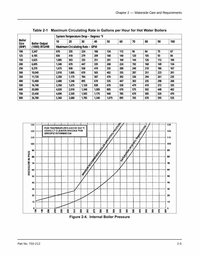
Table 2-1 shows the maximum gpm circulation rate of boilerwater in relat ion to ful l boi ler output and systemtemperature drop.
Multiple Boiler Installations — When multiple boilers areused, care must be taken to ensure adequate or proportionalflow through the boilers. Proportional flow can best beaccomplished by use of balancing valves and gauges in thesupply line from each boiler. If balancing valves or orificeplates are used, a significant pressure drop (e.g., 3 – 5 psi)must be taken across the balancing device to accomplish thepurpose.
Part No. 750-212 2-3
Chapter 2 — Waterside Care and Requirements
If care is not taken to ensure adequate or proportional flowthrough the boilers, wide variations in firing rates between theboilers can result.
In extreme cases, one boiler may be in the high-fire positionwhile the other boiler or boilers may be at low-fire. The netresult would be that the common header water temperatureto the system would not be up to the desired point.
Pump Location — It is recommended that the systemcirculating pumps take suction from the outlet connectionon the boiler, and that they discharge to the system load, inorder to put the boiler and the expansion tank on the suctionside of the pump. The suction side is preferred because itdecreases air entry into the system and does not impose thesystem head on the boiler.
It is common practice to install a standby system circulatingpump. The main circulating pumps are usually locatedadjacent to the boilers in the boiler room.
Pump Operation — Pumps are normally started and stoppedby manual switches. It is also desirable to interlock thepump with the burner so that the burner cannot operateunless the circulating pump is running.
Pressure
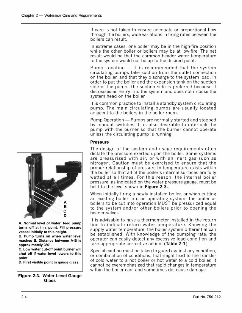
The design of the system and usage requirements oftendictate the pressure exerted upon the boiler. Some systemsare pressurized with air, or with an inert gas such asnitrogen. Caution must be exercised to ensure that theproper relationship of pressure-to-temperature exists withinthe boiler so that all of the boiler’s internal surfaces are fullywetted at all times. For this reason, the internal boilerpressure, as indicated on the water pressure gauge, must beheld to the level shown in Figure 2-3..
When initially firing a newly installed boiler, or when cuttingan existing boiler into an operating system, the boiler orboilers to be cut into operation MUST be pressurized equalto the system and/or other boilers prior to opening theheader valves.
It is advisable to have a thermometer installed in the returnline to indicate return water temperature. Knowing thesupply water temperature, the boiler system differential canbe established. With knowledge of the pumping rate, theoperator can easily detect any excessive load condition andtake appropriate corrective action. (Table 2-1)
Special caution must be taken to guard against any condition,or combination of conditions, that might lead to the transferof cold water to a hot boiler or hot water to a cold boiler. Itcannot be overemphasized that rapid changes in temperaturewithin the boiler can, and sometimes do, cause damage.
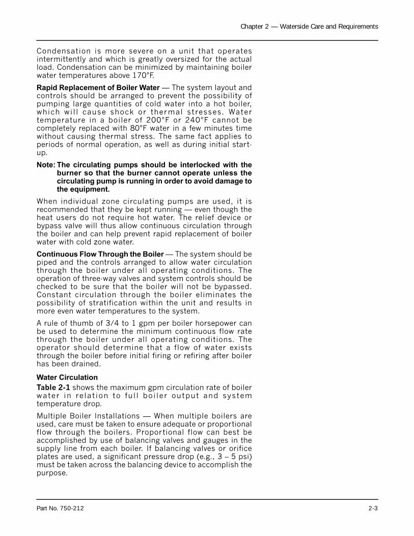
Figure 2-3. Water Level Gauge Glass
A
B
C
A. Normal level of water: feed pump
turns off at this point. Fill pressure
vessel initially to this height.
B. Pump turns on when water level
reaches B. Distance between A-B is
approximately 3/4”.
C. Low water cut-off point burner will
shut off if water level lowers to this
point.
D. First visible point in gauge glass.
D
2-4 Part No. 750-212
Chapter 2 — Waterside Care and Requirements
Table 2-1 Maximum Circulating Rate in Gallons per Hour for Hot Water Boilers
Boiler Size (BHP)
Boiler Output (1000) BTU/HR
System Temperature Drop – Degress °F
10 20 30 40 50 60 70 80 90 100
Maximum Circulating Rate – GPM100 3,347 670 335 224 168 134 112 96 84 75 67125 4,185 836 418 279 209 168 140 120 105 93 84150 5,025 1,005 503 335 251 201 168 144 126 112 100200 6,695 1,340 670 447 335 268 224 192 168 149 134250 8,370 1,675 838 558 419 335 280 240 210 186 167300 10,045 2,010 1,005 670 503 402 335 287 251 223 201350 11,720 2,350 1,175 784 587 470 392 336 294 261 235400 13,400 2,680 1,340 895 670 535 447 383 335 298 268500 16,740 3,350 1,675 1,120 838 670 558 479 419 372 335600 20,080 4,020 2,010 1,340 1,005 805 670 575 502 448 402700 23,430 4,690 2,345 1,565 1,175 940 785 670 585 520 470800 26,780 5,360 2,680 1,785 1,340 1,075 895 765 670 595 535
Figure 2-4. Internal Boiler Pressure
Part No. 750-212 2-5
Chapter 2 — Waterside Care and Requirements
2. Steam Boiler
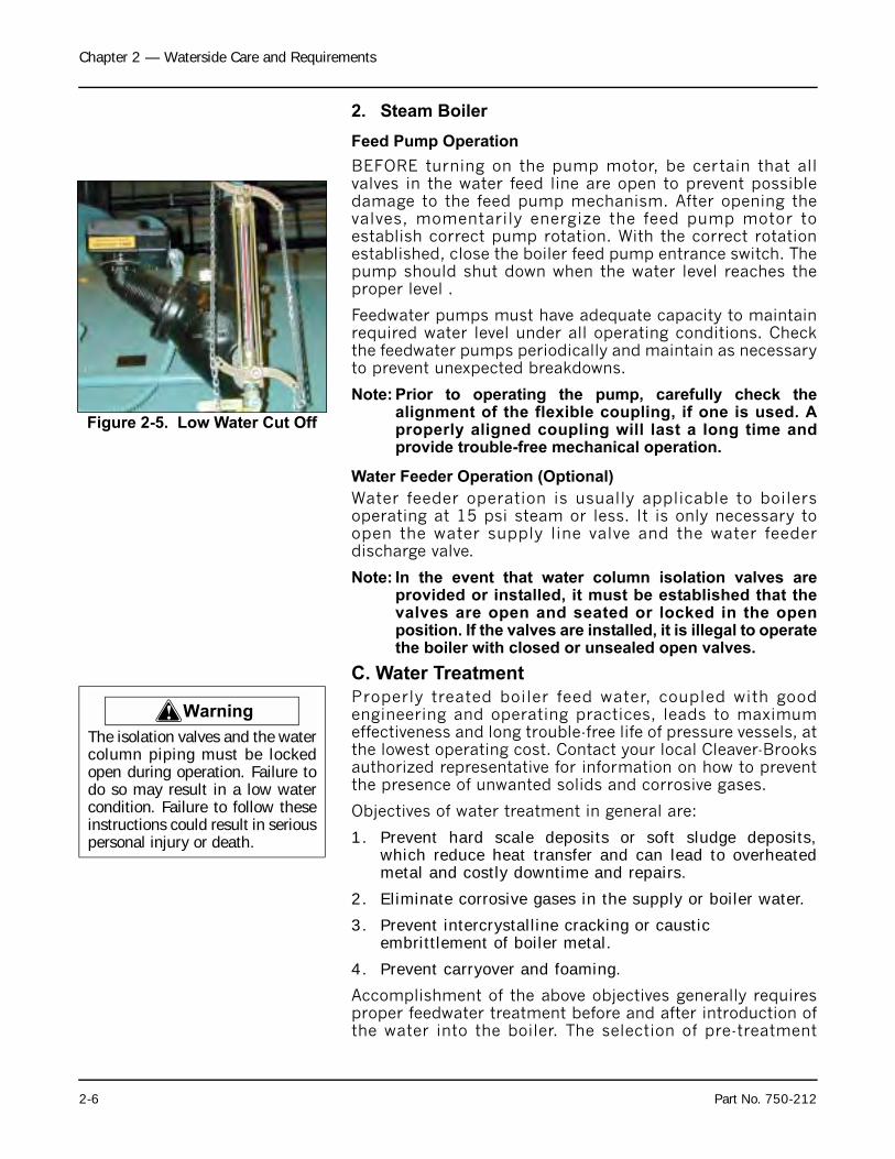
Feed Pump Operation
BEFORE turning on the pump motor, be certain that allvalves in the water feed line are open to prevent possibledamage to the feed pump mechanism. After opening thevalves, momentarily energize the feed pump motor toestablish correct pump rotation. With the correct rotationestablished, close the boiler feed pump entrance switch. Thepump should shut down when the water level reaches theproper level .
Feedwater pumps must have adequate capacity to maintainrequired water level under all operating conditions. Checkthe feedwater pumps periodically and maintain as necessaryto prevent unexpected breakdowns.
Note: Prior to operating the pump, carefully check thealignment of the flexible coupling, if one is used. Aproperly aligned coupling will last a long time andprovide trouble-free mechanical operation.
Water Feeder Operation (Optional)
Water feeder operation is usually applicable to boilersoperating at 15 psi steam or less. It is only necessary toopen the water supply line valve and the water feederdischarge valve.
Note: In the event that water column isolation valves areprovided or installed, it must be established that thevalves are open and seated or locked in the openposition. If the valves are installed, it is illegal to operatethe boiler with closed or unsealed open valves.
C. Water Treatment
Properly treated boiler feed water, coupled with goodengineering and operating practices, leads to maximumeffectiveness and long trouble-free life of pressure vessels, atthe lowest operating cost. Contact your local Cleaver-Brooksauthorized representative for information on how to preventthe presence of unwanted solids and corrosive gases.
Objectives of water treatment in general are:
1. Prevent hard scale deposits or soft sludge deposits,which reduce heat transfer and can lead to overheatedmetal and costly downtime and repairs.
2. Eliminate corrosive gases in the supply or boiler water.
3. Prevent intercrystalline cracking or caustic embrittlement of boiler metal.
4. Prevent carryover and foaming.
Accomplishment of the above objectives generally requiresproper feedwater treatment before and after introduction ofthe water into the boiler. The selection of pre-treatment
Figure 2-5. Low Water Cut Off
! Warning
The isolation valves and the watercolumn piping must be lockedopen during operation. Failure todo so may result in a low watercondition. Failure to follow theseinstructions could result in seriouspersonal injury or death.
2-6 Part No. 750-212
Chapter 2 — Waterside Care and Requirements
processes depends upon the water source, its chemicalcharacteristics, amount of makeup water needed, plantoperating practices, etc. Treating methods include filtering,softening, de-mineralizing, deaerating, and preheating.After-treatment involves chemical treatment of the boilerwater.Because of the variables involved, no single boilercompound can be considered a “cure-all” nor is it advisableto experiment with homemade treating methods. Soundrecommendations and their employment should beaugmented by a periodic analysis of the feedwater, boilerwater, and condensate.
The internal or waterside surfaces of the pressure vesselshould be inspected with enough frequency to determine thepresence of any contamination, accumulations of foreignmatter, or corrosion, and/or pitting. If any of theseconditions are detected, contact your local Cleaver-Brooksauthorized representative for advice on corrective action.
A properly sized water meter should be installed in the rawwater make-up line in order to accurately determine theamount of raw water admitted to the boiler (steam or hotwater) and to aid in maintaining proper watersideconditions.
D. Cleaning
1. Hot Water and Steam Piping
Steam and water piping systems connected to the boilermay contain oil, grease, or foreign matter. The impuritiesmust be removed in order to prevent damage to pressurevessel heating surfaces. On a steam system, the condensateshould be wasted until tests show the elimination ofundesirable impurities. During the period that condensate iswasted, attention must be given to the treatment of the rawwater used as make-up so that an accumulation of unwantedmaterials or corrosion does not occur. For more information,contact your local Cleaver-Brooks authorized representative.
On a hot water system, chemical cleaning is generallynecessary and the entire system should be drained aftertreatment. Consult your local Cleaver-Brooks authorizedrepresentative for recommendations, cleaning compounds,and application procedures.
2. Pressure Vessel
The waterside of the pressure vessel must be kept cleanfrom grease, sludge, and foreign material. Such deposits, ifpresent, will shorten the life of the pressure vessel, willinterfere with efficient operation and functioning of controlof safety devices, and quite possibly cause unnecessary andexpensive re-work, repairs, and downtime.
The installation and operating conditions that the boiler willbe subjected to should be considered and cleaning of the
Part No. 750-212 2-7
Chapter 2 — Waterside Care and Requirements
Notice
waterside of the pressure vessel should be provided duringthe course of initial start-up.
The pressure vessel and the steam and return lines or hotwater piping represent, in effect, a closed system. Althoughthe steam and return (condensate) lines or the hot waterpiping system may have been previously cleaned, it ispossible that:
1. Cleaning has been inadequate.
2. Partial or total old system is involved.
3. Conditions may prevent adequate cleaning of piping.
The pressure vessel waterside should be inspected on aperiodic basis. An inspection will reveal true internalconditions and serve as a check against conditions indicatedby chemical analysis of the boiler water. Inspection shouldbe made three months after initial starting and at regular 6-, 9-, or 12-month intervals thereafter. The frequency offurther periodic inspections will depend upon the internalconditions found.
If any unwanted conditions are observed, contact your localC leaver-Brooks author i zed representa t ive fo rrecommendations.
Any sludge, mud or sediment found will need to be flushedout. If excessive mud or sludge is noticed during theblowdown the scheduling or frequency of blowdown mayneed to be revised. The need for periodic draining orwashout will also be indicated.
Any oil or grease present on the heating surfaces should beremoved promptly by a boil-out with an alkaline detergentsolution.
Temperature of initial fill of water forhydrostatic tests, boil-out, or fornormal operation should be asstated in the ASME Boiler Code.Boil-Out of New Unit
The internal surfaces of a newly installed boiler may have oil,grease or other protective coatings used in manufacturing.Such coatings must be removed because they lower the heattransfer rate and could cause over-heating of a tube. Beforeboiling out procedures may begin, the burner should beready for firing. The operator must be familiar with theprocedure outlined under burner operation.
2-8 Part No. 750-212
Chapter 2 — Waterside Care and Requirements
Your local Cleaver-Brooks authorized representative will beable to recommend a cleaning or boil-out procedure. In theevent such service is unavailable or is yet unscheduled, thefollowing information may be of assistance.
There are several chemicals suitable for boil-out. Onecombination often used is soda ash (sodium carbonate) andcaustic soda (sodium hydroxide) at the rate of 3 to 5 poundseach per 1,000 pounds of water, along with a small amountof laundry detergent added as a wetting agent.
The suggested general procedure for cleaning a boiler is asfollows:
1. Have sufficient cleaning material on hand to completethe job.
2. When dissolving chemicals, the following procedure issuggested. Warm water should be put into a suitablecontainer. Slowly introduce the dry chemical into thewater, stirring it at all times until the chemical iscompletely dissolved. Add the chemical slowly and insmall amounts to prevent excessive heat and turbulence.
3. An over-flow pipe should be attached to one of the topboiler openings and routed to a safe point of discharge.A relief or safety valve tapping is usually used.
4. Water relief valves and steam safety valves must beremoved before adding the boil-out solution so thatneither it nor the grease which it may carry willcontaminate the valves. Use care in removing andreinstalling the valves.
5. All valves in the piping leading to or from the systemmust be closed to prevent the cleaning solution fromgetting into the system.
6. Fill the pressure vessel with clean water until the top ofthe tubes are covered. Add the cleaning solution andthen fill to the top. The temperature of the water used inthe initial fill should be at ambient temperature.
7. The boiler should then be fired intermittently at a lowrate sufficient to hold solution just at the boiling point.
! Warning
Use of a suitable face mask,goggles, rubber gloves, andprotective garments is stronglyrecommended when handling ormixing caustic chemicals. Do notpermit the dry material or theconcentrated solution to come incontact with skin or clothing.Failure to follow these instructionscould result in serious personalinjury or death.
Part No. 750-212 2-9
Chapter 2 — Waterside Care and Requirements
Boil the water for at least five hours. Do not producesteam pressure.
8. Allow a small amount of fresh water to enter the boilerto create a slight overflow that will carry off surfaceimpurities.
9. Continue the boil and overflow process until the waterclears. Shut the burner down.
10. Let the boiler cool to 120°F or less.11. Remove handhole plates and wash the waterside
surfaces thoroughly using a high pressure water stream.
12. Inspect the surfaces. If they are not clean, repeat theboil out.
13. After closing the handholes and reinstalling the safety orrelief valves, fill the boiler and fire it until the water isheated to at least 180°F to drive off any dissolvedgases, which might otherwise corrode the metal.
The above procedure may be omitted in the case of a unitpreviously used or known to be internally clean. However,considerat ion must be g iven to the possibi l i ty ofcontaminating materials entering the boiler from thesystem.
E. Washing Out
1. Hot Water Boiler
In theory, a hot water system and boiler that has beeninitially cleaned, filled with raw water (and water treated),and with no make-up water added, will require no furthercleaning or treatment. However, since the system (new orold) can allow entrance of air and unnoticed or undetectedleakage of water, introductions of raw water make-up or airmay lead to pitting, corrosion and formation of sludge,sediment, scale, etc., on the pressure vessel waterside.
If the operator is absolutely certain that the system is tight,then an annual waterside inspection may be sufficient.However, if there is any doubt, the pressure vessel watersideshould be inspected no later than three months after initiallyplacing the boiler into operation, and periodically thereafteras indicated by conditions observed during inspections.
2. Steam Boiler
No later than three months after initially placing the boilerinto operation and starting service, and thereafter asconditions warrant, the pressure vessel should be drainedafter being properly cooled to near ambient temperature.Handhole covers should be removed and waterside surfaces
! Warning
Be sure to drain the hot water toa safe point of discharge to avoidscalding. Failure to follow theseinstructions could result in seriouspersonal injury or death.
2-10 Part No. 750-212
Chapter 2 — Waterside Care and Requirements
should be inspected for corrosion, pitting, or formation ofdeposits.
Flushing of Pressure Vessel Interior
Upon completion of the inspection, the pressure vesselinterior should be flushed out, as required, with a highpressure hose. If deposits are not fully removed by flushing,a consultation may be required with your local Cleaver-Brooks authorized representative. In extreme cases, it maybe necessary to resort to acid cleaning. Professional adviceis recommended if acid cleaning is required.
The inspections will indicate the effectiveness of thefeedwater treatment. The effectiveness of treatment, thewater conditions, and the amount of fresh water make-uprequired are all factors to be considered in establishingfrequency of future pressure vessel washouts. Contact yourlocal Cleaver-Brooks authorized representative for moreinformation.
F. Fireside Cleaning
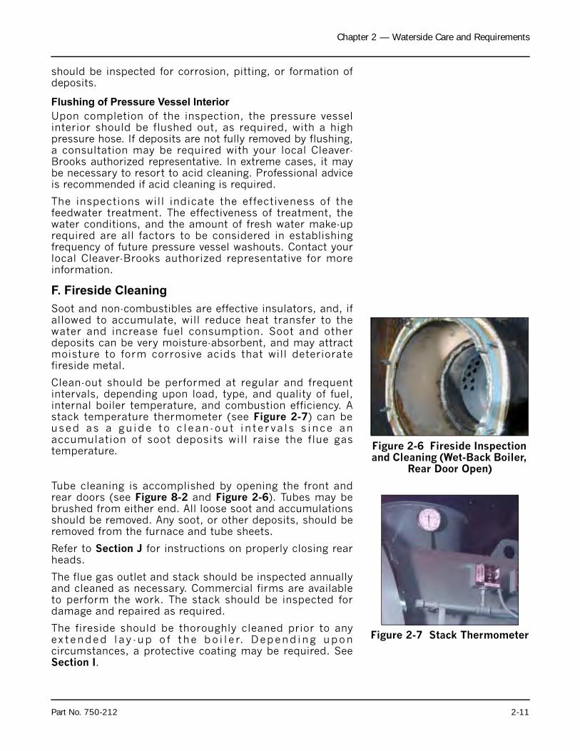
Soot and non-combustibles are effective insulators, and, ifallowed to accumulate, will reduce heat transfer to thewater and increase fuel consumption. Soot and otherdeposits can be very moisture-absorbent, and may attractmoisture to form corrosive acids that will deterioratefireside metal.
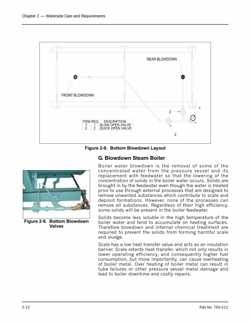
Clean-out should be performed at regular and frequentintervals, depending upon load, type, and quality of fuel,internal boiler temperature, and combustion efficiency. Astack temperature thermometer (see Figure 2-7) can beused as a gu ide to c lean -ou t in te r va l s s ince anaccumulation of soot deposits will raise the flue gastemperature.
Tube cleaning is accomplished by opening the front andrear doors (see Figure 8-2 and Figure 2-6). Tubes may bebrushed from either end. All loose soot and accumulationsshould be removed. Any soot, or other deposits, should beremoved from the furnace and tube sheets.
Refer to Section J for instructions on properly closing rearheads.
The flue gas outlet and stack should be inspected annuallyand cleaned as necessary. Commercial firms are availableto perform the work. The stack should be inspected fordamage and repaired as required.
The fireside should be thoroughly cleaned prior to anyex tended l ay -up o f t he bo i l e r. Depend ing uponcircumstances, a protective coating may be required. SeeSection I.
Figure 2-6 Fireside Inspection and Cleaning (Wet-Back Boiler,
Rear Door Open)
Figure 2-7 Stack Thermometer
Part No. 750-212 2-11
Chapter 2 — Waterside Care and Requirements
G. Blowdown Steam Boiler
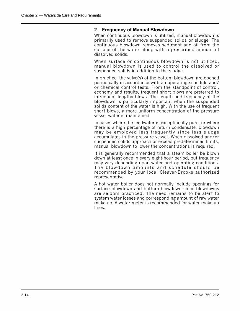
Boiler water blowdown is the removal of some of theconcentrated water from the pressure vessel and itsreplacement with feedwater so that the lowering of theconcentration of solids in the boiler water occurs. Solids arebrought in by the feedwater even though the water is treatedprior to use through external processes that are designed toremove unwanted substances which contribute to scale anddeposit formations. However, none of the processes canremove all substances. Regardless of their high efficiency,some solids will be present in the boiler feedwater.
Solids become less soluble in the high temperature of theboiler water and tend to accumulate on heating surfaces.Therefore blowdown and internal chemical treatment arerequired to prevent the solids from forming harmful scaleand sludge.
Scale has a low heat transfer value and acts as an insulationbarrier. Scale retards heat transfer, which not only results inlower operating efficiency, and consequently higher fuelconsumption, but more importantly, can cause overheatingof boiler metal. Over heating of boiler metal can result intube failures or other pressure vessel metal damage andlead to boiler downtime and costly repairs.
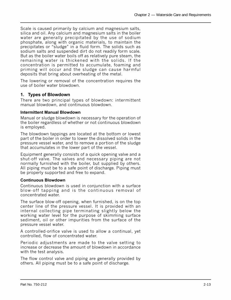
Figure 2-8. Bottom Blowdown Layout
FRONT BLOWDOWN
2
2
1
REAR BLOWDOWN
SLOW OPEN VALVE
DESCRIPTION
QUICK OPEN VALVE
REQ
2
1
2
1
ITEM
Figure 2-9. Bottom Blowdown Valves
2-12 Part No. 750-212
Chapter 2 — Waterside Care and Requirements
Scale is caused primarily by calcium and magnesium salts,silica and oil. Any calcium and magnesium salts in the boilerwater are generally precipitated by the use of sodiumphosphate, along with organic materials, to maintain theprecipitates or “sludge” in a fluid form. The solids such assodium salts and suspended dirt do not readily form scale.But as the boiler water boils off as relatively pure steam, theremaining water is thickened with the solids. If theconcentration is permitted to accumulate, foaming andpriming will occur and the sludge can cause harmfuldeposits that bring about overheating of the metal.
The lowering or removal of the concentration requires theuse of boiler water blowdown.
1. Types of Blowdown
There are two principal types of blowdown: intermittentmanual blowdown, and continuous blowdown.
Intermittent Manual Blowdown
Manual or sludge blowdown is necessary for the operation ofthe boiler regardless of whether or not continuous blowdownis employed.
The blowdown tappings are located at the bottom or lowestpart of the boiler in order to lower the dissolved solids in thepressure vessel water, and to remove a portion of the sludgethat accumulates in the lower part of the vessel.
Equipment generally consists of a quick opening valve and ashut-off valve. The valves and necessary piping are notnormally furnished with the boiler, but supplied by others.All piping must be to a safe point of discharge. Piping mustbe properly supported and free to expand.
Continuous Blowdown
Continuous blowdown is used in conjunction with a surfaceblow-of f tapping and is the continuous removal ofconcentrated water.
The surface blow-off opening, when furnished, is on the topcenter line of the pressure vessel. It is provided with aninternal collecting pipe terminating slightly below theworking water level for the purpose of skimming surfacesediment, oil or other impurities from the surface of thepressure vessel water.
A controlled-orifice valve is used to allow a continual, yetcontrolled, flow of concentrated water.
Periodic adjustments are made to the valve setting toincrease or decrease the amount of blowdown in accordancewith the test analysis.
The flow control valve and piping are generally provided byothers. All piping must be to a safe point of discharge.
Part No. 750-212 2-13
Chapter 2 — Waterside Care and Requirements
2. Frequency of Manual Blowdown
When continuous blowdown is utilized, manual blowdown isprimarily used to remove suspended solids or sludge. Thecontinuous blowdown removes sediment and oil from thesurface of the water along with a prescribed amount ofdissolved solids.
When surface or continuous blowdown is not utilized,manual blowdown is used to control the dissolved orsuspended solids in addition to the sludge.
In practice, the valve(s) of the bottom blowdown are openedperiodically in accordance with an operating schedule and/or chemical control tests. From the standpoint of control,economy and results, frequent short blows are preferred toinfrequent lengthy blows. The length and frequency of theblowdown is particularly important when the suspendedsolids content of the water is high. With the use of frequentshort blows, a more uniform concentration of the pressurevessel water is maintained.
In cases where the feedwater is exceptionally pure, or wherethere is a high percentage of return condensate, blowdownmay be employed less frequently since less sludgeaccumulates in the pressure vessel. When dissolved and/orsuspended solids approach or exceed predetermined limits,manual blowdown to lower the concentrations is required.
It is generally recommended that a steam boiler be blowndown at least once in every eight-hour period, but frequencymay vary depending upon water and operating conditions.The b lowdown amounts and schedu le shou ld berecommended by your local Cleaver-Brooks authorizedrepresentative.
A hot water boiler does not normally include openings forsurface blowdown and bottom blowdown since blowdownsare seldom practiced. The need remains to be alert tosystem water losses and corresponding amount of raw watermake-up. A water meter is recommended for water make-uplines.
2-14 Part No. 750-212
Chapter 2 — Waterside Care and Requirements
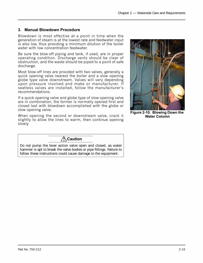
3. Manual Blowdown Procedure
Blowdown is most effective at a point in time when thegeneration of steam is at the lowest rate and feedwater inputis also low, thus providing a minimum dilution of the boilerwater with low concentration feedwater.
Be sure the blow-off piping and tank, if used, are in properoperating condition. Discharge vents should be clear ofobstruction, and the waste should be piped to a point of safedischarge.
Most blow-off lines are provided with two valves, generally aquick opening valve nearest the boiler and a slow openingglobe type valve downstream. Valves will vary dependingupon pressure involved and make or manufacturer. Ifseatless valves are installed, follow the manufacturer’srecommendations.
If a quick opening valve and globe type of slow opening valveare in combination, the former is normally opened first andclosed last with blowdown accomplished with the globe orslow opening valve.
When opening the second or downstream valve, crack itslightly to allow the lines to warm, then continue openingslowly
Figure 2-10. Blowing Down the Water Column
! Caution
Do not pump the lever action valve open and closed, as waterhammer is apt to break the valve bodies or pipe fittings. Failure tofollow these instructions could cause damage to the equipment.
Part No. 750-212 2-15
Chapter 2 — Waterside Care and Requirements
The length of each blow should be determined by actualwater analysis. Lowering the water in the gauge glassapproximately 1/2" is often acceptable as a guide toadequate blow. However, lowering the water 1/2" should notbe interpreted as a rule since water analysis proceduresshould prevail. If the glass cannot be viewed by the partyoperating the valve, another operator should watch the glassand direct the valve operator.
Close the downstream (slow opening) valve first and as fastas possible. Then close the valve next to the boiler. Slightlycrack the downstream valve and then close it tightly. Underno circumstances should a blow-off valve be left open andthe operator should never leave until the blowdownoperation is completed and the valves are closed.
H. Periodic Inspection
Insurance regulations or local laws will require a periodicinspection of the pressure vessel by an authorized inspector.Sufficient notice is generally given to permit removal of theboiler from service and preparation for inspection.
When shutting down the boiler, the load should be reducedgradually and the pressure vessel cooled at a rate thatavoids damaging temperature differential that can causeharmful stresses. Vessels should not normally be draineduntil all pressure is relieved — again to prevent unevencontraction and temperature differentials that can causeexpanded tubes to leak. Draining the unit too quickly maycause the baking of deposits that may be present on theheating surfaces. Some heat, however, may be desirable todry out the interior of the boiler.
If the internal inspection is being made at the request of anauthorized inspector, it is well to ask the inspector toobserve the conditions prior to cleaning or flushing ofwaterside surfaces.
Be certain that a supply of manhole and handhole gaskets isavailable, along with any other gaskets or items needed toplace the unit back into operation after inspection.
Have available information on the boiler design, dimensions,generating capacity, operating pressure or temperature,time in service, defects found previously, and any repairs ormodifications. Also have available for reference records ofprevious inspections.
Figure 2-11. Vent Valve on Water Column
Vent Valve
! Warning
To avoid the hazard of electrical shock, we recommend the use ofa low voltage flashlight during an internal inspection. Preferably,inspectors should work in pairs. Failure to follow theseinstructions could result in serious personal injury or death.
2-16 Part No. 750-212
Chapter 2 — Waterside Care and Requirements
Be prepared to perform any testing required by the inspectorincluding a hydrostatic test.
After proper cooling and draining of the vessel, flush out thewaterside with a high pressure water hose. Remove any scaleor deposits from the waterside surfaces and check forinternal or external corrosion and leakage.
The fireside surface should also be thoroughly cleaned sothat metal surfaces, welds, joints, tube ends, fittings and anyprevious repairs can be readily checked.
Be sure that steam valves, and valves to expansion tank (hotwater), feedwater valves, blow-off valves, all fuel valves,valves to expansion tank, and electrical switches are shut offprior to opening handholes, manhole and front or rear doors.Adequately vent the pressure vessel prior to entry.
Clean out the low-water cutoff piping, the water levelcontrols and cross-connecting pipes. Replace the watergauge glass and clean out the water cocks. Also check andclean the drain and the blowdown valves and piping.
Check all water and steam piping and valves for leaks, wear,corrosion, and other damage. Replace or repair as required.
I. Preparation for Extended Lay-Up
Many boilers used for heating or seasonal loads or forstandby service may have extended periods of non-use.Special attention must be given to idle boilers so that neitherwaterside nor fireside surfaces are allowed to deterioratefrom corrosion.
Too many conditions exist to lay down definite rules. Thereare two methods of storage: wet or dry. Your local Cleaver-Brooks authorized representative can recommend the bettermethod depending upon circumstances in the particularinstallation.
Whichever method is used, common sense dictates aperiodic recheck of fireside and waterside conditions duringlay-up to allow variations from the above methods for specialarea or jobsite conditions.
Swing open the boiler head at the stack end of the unit toprevent flow of warm, moist air through the boiler tubes.
Although pollution control regulations may continue to limitthe permissible sulphur content of fuel oils, care must betaken to avoid corrosion problems that sulphur can cause,especially in a boiler that is seasonally shutdown. Dormantperiods, and even frequent shutdowns, expose the firesidesurfaces to condensation below the dew point duringcooling. Moisture and any sulphur residue can form an acidsolution. Under certain conditions, and especially in areaswith high humidity, the corrosive effect of the acid will beserious enough to eat through or severely damage boiler
Part No. 750-212 2-17
Chapter 2 — Waterside Care and Requirements
tubes or other metal heating surfaces during the time that aboiler is out of service.
The condition does not generally occur during normal firingoperation, because the high temperature of operationvaporizes any condensation. However, proper boileroperation must be maintained, especially with a hot waterboiler, to prevent the flue gases from falling below the dewpoint.
At the start of lay-up, thoroughly clean the fireside byremoving any soot or other products of combustion from thetubes, tube sheets and other fireside surfaces. Brushing willgenerally suffice. Sweep away or vacuum any accumulation.The fireside surfaces may be flushed with water. However, allmoisture must be eliminated after flushing and the surfacedried by blowing air or applying some form of heat. It is goodpractice to protect the cleaned surfaces by coating themwith an anti-corrosive material to prevent rust.
To prevent condensation from forming in the control cabinet,keep the control circuit energized. For extended lay-upperiods, especially where high humidity or large swings inambient temperature occur, the program relay should beremoved and stored in a dry atmosphere.
Dry storage is generally employed when the boiler will be outof service for a significant period of time, or where freezingtemperatures may exist. In the dry storage method the boilermust be thoroughly dried because any moisture would causecorrosion. Both fireside and waterside surfaces must becleaned of all scale, deposits, soot, etc. Steps must be takento eliminate moisture by placing moisture-absorbingmaterials such as quick lime (at 2 pounds for 3 cubic feet ofvolume) or silica gel (at 5 pounds for 30 cubic feet of volume)on trays inside the vessel. Fireside surfaces may be coatedwith an anticorrosive material, or grease or tar paint.Refractories should be brushed clean and wash-coated. Allopenings to the pressure vessel, such as manhole andhandholes, should be shut tightly. Feedwater and steamvalves should be closed. Damper and vents should be closedto prevent air from reaching fireside surfaces. Periodicinspection should be made and absorption materialsrenewed.
Wet storage is generally used for a boiler held in standbycondition or in cases where dry storage is not practical. Thepossibility of freezing temperatures must be considered.Care must again be taken to protect metal surfaces.Variables preclude definite recommendations. However, it issuggested that the pressure vessel be drained, thoroughlycleaned internally, and re-filled to overflowing with treatedwater. If deaerated water is not available, the unit should befired to boil the water for a short period of time. Additionalchemicals may be suggested by your local Cleaver-Brooksauthorized representative to minimize corrosion. Internal
2-18 Part No. 750-212
Chapter 2 — Waterside Care and Requirements
water pressure should be maintained at greater thanatmospheric pressure. Nitrogen is often used to pressurizethe vessel. Fireside surfaces must be thoroughly cleaned andrefractory should be wash-coated.
J. Opening And Closing Doors
1. Opening Front or Rear Door
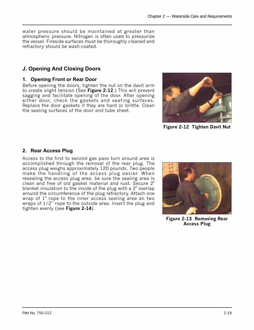
Before opening the doors, tighten the nut on the davit armto create slight tension (See Figure 2-12.) This will preventsagging and facilitate opening of the door. After openingeither door, check the gaskets and seating surfaces.Replace the door gaskets if they are hard or brittle. Cleanthe sealing surfaces of the door and tube sheet.
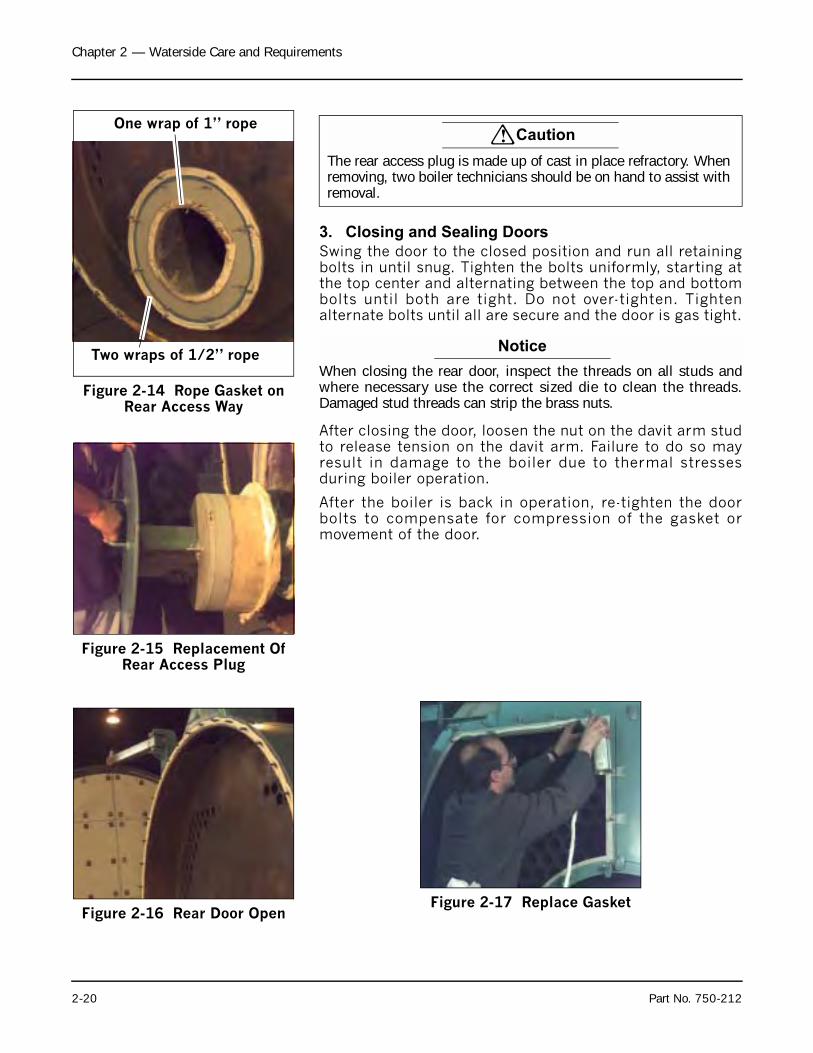
2. Rear Access Plug
Access to the first to second gas pass turn around area isaccomplished through the removal of the rear plug. Theaccess plug weighs approximately 120 pounds. Two peoplemake the handling of the access plug easier. Whenresealing the access plug area, be sure the sealing area isclean and free of old gasket material and rust. Secure 2"blanket insulation to the inside of the plug with a 2" overlaparound the circumference of the plug refractory. Attach onewrap of 1" rope to the inner access sealing area an twowraps of 1/2” rope to the outside area. Insert the plug andtighten evenly (see Figure 2-14).
Figure 2-12 Tighten Davit Nut
Figure 2-13 Removing Rear Access Plug
Part No. 750-212 2-19
Chapter 2 — Waterside Care and Requirements
3. Closing and Sealing Doors
Swing the door to the closed position and run all retainingbolts in until snug. Tighten the bolts uniformly, starting atthe top center and alternating between the top and bottombolts until both are tight. Do not over-tighten. Tightenalternate bolts until all are secure and the door is gas tight.
Notice
When closing the rear door, inspect the threads on all studs andwhere necessary use the correct sized die to clean the threads.Damaged stud threads can strip the brass nuts.
After closing the door, loosen the nut on the davit arm studto release tension on the davit arm. Failure to do so mayresult in damage to the boiler due to thermal stressesduring boiler operation.
After the boiler is back in operation, re-tighten the doorbolts to compensate for compression of the gasket ormovement of the door.
Figure 2-14 Rope Gasket on Rear Access Way
Two wraps of 1/2” rope
One wrap of 1” rope! Caution
The rear access plug is made up of cast in place refractory. When removing, two boiler technicians should be on hand to assist with removal.
Figure 2-15 Replacement Of Rear Access Plug
Figure 2-16 Rear Door OpenFigure 2-17 Replace Gasket
2-20 Part No. 750-212
Chapter 3
Sequence of Operation
A. General . . . . . . . . . . . . . . . . . . . . . . . . . . . . . . . . . . . . . . . . . . . . . . . 3-2
B. Circuit and Interlock Controls . . . . . . . . . . . . . . . . . . . . . . . . . . . . . . 3-3
C. Sequence of Operation — Oil or Gas . . . . . . . . . . . . . . . . . . . . . . . . 3-4
1. Pre-purge Cycle . . . . . . . . . . . . . . . . . . . . . . . . . . . . . . . . . 3-4
2. Ignition Cycle . . . . . . . . . . . . . . . . . . . . . . . . . . . . . . . . . . 3-5
3. Run Cycle . . . . . . . . . . . . . . . . . . . . . . . . . . . . . . . . . . . . . 3-6
4. Burner Shutdown — Post Purge . . . . . . . . . . . . . . . . . . . . 3-6
D. Flame Loss Sequence . . . . . . . . . . . . . . . . . . . . . . . . . . . . . . . . . . . . 3-7
1. No Pilot Flame . . . . . . . . . . . . . . . . . . . . . . . . . . . . . . . . . . 3-7
Pilot But No Main Flame . . . . . . . . . . . . . . . . . . . . . . . . . . . . . . 3-7
Loss of Flame . . . . . . . . . . . . . . . . . . . . . . . . . . . . . . . . . . . . . . . 3-7
Milwaukee, Wisconsin
www.cleaver-brooks.com

Chapter 3 — Sequence of Operation
A. General
Chapter 3 outlines the electrical sequencing of variouscontrols through the pre-purge, ignition, run, and shutdowncycles of the burner.
The program relay establishes the sequence of operation anddirects the operation of all other controls and components toprovide an overall operating sequence.
Note: The make or model of the program relay provided willvary depending upon job specifications. The followingsequence applies regardless of the make or model. Pleaserefer to the Wiring Diagram (WD) prepared by Cleaver-Brooksfor your specific installation.
Abbreviations for the various electrical components are listedin Table 3-1. The sequences outlined in Chapter 3 employspecific nomenclature to aid in applying the text to the wiringdiagram.
The burner and control system are in starting condition whenthe following conditions exist:
1. Boiler water is up to the correct level, closing the low-water cutoff switch.
2. The low-water light (panel) is off.
3. The operating limit pressure control (steam boiler) or theoperating limit temperature control (hot water boiler) andhigh limit pressure or temperature control are below theircutoff setting.
4. All applicable limits are correct for burner operation.
5. The load demand light glows (fuel pressure, temperature).
6. Reset manual reset (water, fuel pressure, operatinglimits).
All entrance switches are closed and power is present at theline terminals of:
1. Blower motor starter
2. Air compressor motor starter (if provided)
3. Oil pump motor starter (if provided)
The sequences do not attempt to correlate the action of thefuel supply system or feedwater system except for theinterlock controls that directly relate to the action of theprogram relay. Chapter 4 and Chapter 5 contain set-up andoperating instructions for the “F” Series ProFire burner.Chapter 6 and Chapter 7 contain set-up and operationinstructions for the “D” Series ProFire burner.
3-2 Part No. 750-212
Chapter 3 — Sequence of Operation
B. Circuit and Interlock Controls
The burner control circuit is a two-wire system designed for115 VAC, 60 Hz, single-phase power.
The electrical portion of the boiler is made up of individualcircuits with controls that are wired in a manner designed toprovide a safe workable system. The program relay providesconnection points for the interconnection of the variouscircuits.
The controls used vary depending upon the fuel oil or gas andthe specific requirement of applicable regulatory bodies.Refer to the boiler wiring diagram to determine the actualcontrols provided. The circuits and controls normally used inthe circuits follow and are referred to in the followingsequence of operation.
Limit Circuit
• Burner switch (BS)
• Operating limit control (OLC) – pressure or temperature
• High limit control (HLC) – pressure or temperature
• Low-water cutoff (LWCO)
• Gas-oil selector switch (GOS) – (Combination burner only)
• Low gas pressures switch (LGPS)
• High gas pressure switch (HGPS)
• Fuel valve over travel interlock circuit
• Main gas valve auxiliary switch (MGVAS)
Blower Motor Starter Circuit
• Blower motor starter (BMS)
• Air compressor motor starter (ACMS) (if provided)
Running lnterlock Circuit
• Blower motor starter interlock (BMSI)
• Combustion air proving switch (CAPS)
• Atomizing air proving switch (AAPS) (if provided)
Low Fire Proving Circuit
• Low fire switch (LFS)
Pilot Ignition Circuit
• Gas pilot valve (GPV)
• Ignition transformer (IT)
• Gas pilot vent valve (GPVV) (if provided)
Part No. 750-212 3-3
Chapter 3 — Sequence of Operation
Flame Detector Circuit
• Flame detector (FD)
Main fuel valve circuit
• Main gas valve (MGV)
• Main gas vent valve (MGVV) (if provided)
• Oil valve (OV)
• Main fuel valve light (FVL)
Firing Rate Circuit
• Modulating damper motor (MDM)
• Manual-automatic switch (MAS)
• Manual flame control (MFC)
• Modulating control (MC)
High Fire Proving Circuit
• High fire switch (HFS)
Running Interlock and Limit Circuit
• Low oil pressure switch (LOPS)
• High oil temperature switch (HOTS)
• Auxiliary low-water cutoff (ALWCO)
To comply with requirements of insurance underwriters suchas Factory Mutual (FM), Industrial Risk Insurers (IRI) orothers, additional interlock devices may be used in addition tothe circuits mentioned in Section B.
C. Sequence of Operation — Oil or Gas
On a combination fuel unit, the gas/oil switch must be set forthe proper fuel.
The following sequence occurs with power present at theprogram relay (PR) input terminals and with all otheroperating conditions satisfied.
1. Pre-purge Cycle
When the burner switch (BS) is turned “on,” and controlswired in the “limit” and “fuel valve interlock” circuits areclosed and no flame signal is present, the “blower motor startcircuit” is powered energizing the blower motor starter (BMS).The load demand light (LDL) turns on. When firing oil, the aircompressor motor starter (ACMS) (if provided) is alsopowered.
At the same time, the program relay signals the modulatingdamper motor (MDM) to open the air damper. The damperbegins to open and drives to its full open or high fire position.Opening the damper motor allows a flow of purging airthrough the boiler prior to the ignition cycle.
3-4 Part No. 750-212
Chapter 3 — Sequence of Operation
On all boilers the circuitry will include a high fire switch (HFS).The purpose of the switch is to prove that the modulatingdamper motor (MDM) has driven the damper to the openposition during the pre-purge cycle.
The controls wired into the “running interlock circuit” must beclosed within 10 seconds after the start sequence. In theevent any of the controls are not closed at this time, or if theysubsequently open, the program relay will go into a safetyshutdown.
At the completion of the high fire purge period, the programrelay signals the modulating damper motor (MDM) to drivethe air damper to its low fire position.
To assure that the system is in low fire position prior toignition, the low fire switch (LFS) must be closed to completethe “low fire proving circuit.” The sequence will stop and holduntil the modulating damper motor (MDM) has returned tothe low fire position and the contacts of the low fire switch(LFS) are closed. Once the low fire switch is closed, thesequence is allowed to continue.
Note: The ignition trial cannot be started if flame or a flamesimulating condition is sensed during the pre-purge period. Asafety shutdown will occur if flame is sensed at this time.
2. Ignition Cycle
The ignition transformer (IT) and gas pilot valve (GPV) areenergized from the appropriate pilot ignition terminal.
The pilot flame must be established and proven by the flamedetector (FD) within a 10 second period in order for theignition cycle to continue. If for any reason this does nothappen, the system will shut down and safety lockout willoccur.
With a proven pilot, the main fuel valve(s) (OV or MGV) isenergized and the main fuel valve light (FVL) in the panel islighted. The main flame is ignited and the trial period forproving the main flame begins. It lasts 10 seconds for light oiland/or natural gas. At the end of the proving period, if theflame detector still detects main f lame, the ignitiontransformer and pilot valve are deenergized and pilot flame isextinguished.
Part No. 750-212 3-5
Chapter 3 — Sequence of Operation
Note: If the main flame does not light, or stay lit, the fuel valvewill close. The safety switch will trip to lock out the control.Refer to Flame Loss Sequence (Section D) for description ofaction.
3. Run Cycle
With main flame established, the program relay releases themodulating damper motor (MDM) from its low fire position tocontrol by either the manual flame control (MFC) or themodulating control (MC), depending upon the position of themanual-automatic switch (MAS). This allows operation inranges above low fire.
With the manual-automatic switch (MAS) set at automatic,subsequent modulated firing will be at the command of themodulating control (MC), which governs the position of themodulating damper motor (MDM). The air damper and fuelvalves are actuated by the motor through a linkage.
Note: Normal operation of the burner should be with theswitch in the automatic position and under the direction of themodulating control. The manual position is provided for initialadjustment of the burner over the entire firing range. When ashutdown occurs while operating in the manual position atother than low fire, the damper will not be in a closed position,thus allowing more air than desired to flow through the boiler.Excess air flow subjects the pressure vessel metal andrefractory to undesirable conditions.
The burner starting cycle is now complete. The (LDL) and(FVL) lights on the panel remain lit. Demand firing continuesas required by load conditions.
4. Burner Shutdown — Post Purge
The burner will fire until steam pressure or water temperaturein excess of demand is generated. With modulated firing, themodulating damper motor (MDM) should return to the low fireposition before the operating limit control (OLC) opens. Whenthe limit control circuit is opened, the following sequenceoccurs:
1. The main fuel valve circuit is deenergized, causing themain fuel valve (MGV) or (OV) to close. The flame isextinguished. The control panel lights (LDL) and (FVL) areturned off. The blower motor continues to run to force airthrough the boiler for the post purge period.
! Warning
The cause for loss of flame or any other unusual conditionshould be investigated and corrected before attempting torestart. Failure to follow these instructions could result inserious personal injury or death.
3-6 Part No. 750-212
Chapter 3 — Sequence of Operation
2. The blower motor start circuit is deenergized at the endof the post purge cycle and the shutdown cycle iscomplete.
3. The program relay is now ready for subsequent recycling,and when steam pressure or water temperature drops toclose the contacts of the operating control, the burneragain goes through its normal starting and operatingcycle.
D. Flame Loss Sequence
The program relay will recycle automatically each time theoperating control closes, or after a power failure. It willlockout following a safety shutdown caused by failure to ignitethe pilot, or the main flame, or by loss of flame. Lockout willalso occur if flame or flame simulating condition occursduring the pre-purge period or any time the burner switch isopen.
The control will prevent start-up or ignition if limit circuitcontrols or fuel valve interlocks are open. The control will lockout upon any abnormal condition affecting air supervisorycontrols wired in the running interlock circuit.
1. No Pilot Flame
The pilot flame must be ignited and proven within a 10-secondperiod after the ignition cycle begins. If not proven within thisperiod, the main fuel valve circuit will not be powered and thefuel valve(s) will not be energized. The ignition circuit isimmediately deenergized and the pilot valve closes, the resetswitch lights and lockout occurs immediately.
The blower motor will continue to operate. The flame failurelight and the alarm bell (optional) are energized 10 secondslater.
The blower motor will be deenergized. The lockout switchmust be manually reset before operation can be resumed.(Refer to the previous caution.)
2. Pilot But No Main Flame
When the pilot flame is proven, the main fuel valve circuit isenergized. The pilot flame will be extinguished 10 secondslater. The flame detecting circuit will respond to deenergizethe main fuel valve circuit within 2 to 4 seconds to stop the
! Caution
The lockout switch must be manually reset following asafety shutdown. The cause for loss of flame or any unusualcondition should be investigated and corrected beforeattempting to restart. Failure to follow these instructionscould cause damage to the equipment.
Part No. 750-212 3-7
Chapter 3 — Sequence of Operation
flow of fuel. The reset switch lights and lockout occursimmediately. The blower motor will continue to operate.
The flame failure light and alarm bell (optional) are energized10 seconds later.
The blower motor will be deenergized. The lockout switchmust be manually reset before operation can be resumed.(Refer to the previous caution.)
3. Loss of Flame
If a flame outage occurs during normal operation and/or theflame is no longer sensed by the detector, the flame relay willtrip within 2 to 4 seconds to deenergize the fuel valve circuitand shut off the fuel flow. The reset switch lights and lockoutoccurs immediately. The blower motor continues operation.The flame failure light and alarm bell (optional) are energized10 seconds later.
The blower motor will be deenergized. The lockout switchmust be manually reset before operation can be resumed.(Refer to the previous caution.)
If the burner will not start, or upon a safety lockout, theTroubleshooting section in Chapter 8 and the technicalbulletin should be referred to for assistance in pinpointingproblems that may not be readily apparent.
The program relay has the capability to self-diagnose and todisplay a code or message that indicates the failure condition.Refer to the control bulletin for specifics and suggestedremedies. Familiarity with the program relay and othercontrols in the system can be obtained by studying thecontents of the manual and this bulletin.
Knowledge of the system and its controls will maketroubleshooting much easier. Costly down time or delays canbe prevented by systematic checks of the actual operationagainst the normal sequence to determine the stage at whichperformance deviates from normal. Following a routine maypossibly eliminate overlooking an obvious condition, often onethat is relatively simple to correct.
Remember, a safety device, for the most part, is doing its jobwhen it shuts down or refuses to operate. Never attempt tocircumvent any of the safety features.
Preventive maintenance and scheduled inspection of allcomponents should be followed. Periodic checking of the relayis recommended to see that a safety lockout will occur underconditions of failure to ignite either pilot or main flame, orfrom loss of flame.
3-8 Part No. 750-212
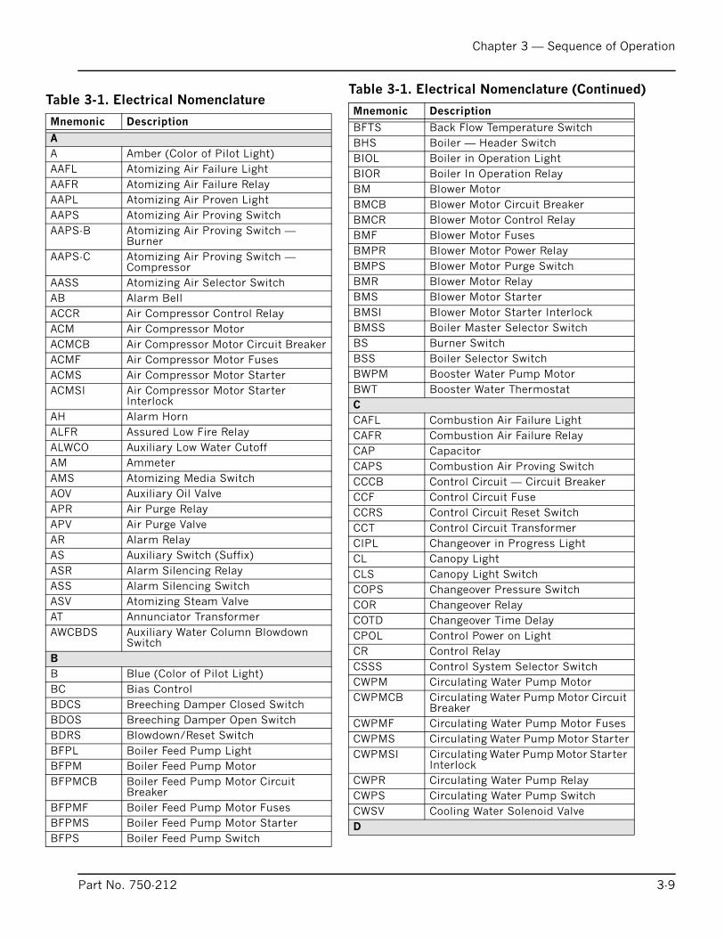
Chapter 3 — Sequence of Operation
Table 3-1. Electrical Nomenclature
Mnemonic Description
A
A Amber (Color of Pilot Light)
AAFL Atomizing Air Failure Light
AAFR Atomizing Air Failure Relay
AAPL Atomizing Air Proven Light
AAPS Atomizing Air Proving Switch
AAPS-B Atomizing Air Proving Switch — Burner
AAPS-C Atomizing Air Proving Switch — Compressor
AASS Atomizing Air Selector Switch
AB Alarm Bell
ACCR Air Compressor Control Relay
ACM Air Compressor Motor
ACMCB Air Compressor Motor Circuit Breaker
ACMF Air Compressor Motor Fuses
ACMS Air Compressor Motor Starter
ACMSI Air Compressor Motor Starter Interlock
AH Alarm Horn
ALFR Assured Low Fire Relay
ALWCO Auxiliary Low Water Cutoff
AM Ammeter
AMS Atomizing Media Switch
AOV Auxiliary Oil Valve
APR Air Purge Relay
APV Air Purge Valve
AR Alarm Relay
AS Auxiliary Switch (Suffix)
ASR Alarm Silencing Relay
ASS Alarm Silencing Switch
ASV Atomizing Steam Valve
AT Annunciator Transformer
AWCBDS Auxiliary Water Column Blowdown Switch
B
B Blue (Color of Pilot Light)
BC Bias Control
BDCS Breeching Damper Closed Switch
BDOS Breeching Damper Open Switch
BDRS Blowdown/Reset Switch
BFPL Boiler Feed Pump Light
BFPM Boiler Feed Pump Motor
BFPMCB Boiler Feed Pump Motor Circuit Breaker
BFPMF Boiler Feed Pump Motor Fuses
BFPMS Boiler Feed Pump Motor Starter
BFPS Boiler Feed Pump Switch
B
B
B
B
B
B
B
B
B
B
B
B
B
B
B
B
B
B
C
C
C
C
C
C
C
C
C
C
C
C
C
C
C
C
C
C
C
C
C
C
C
C
C
C
D
Ta
M
Part No. 750-212
FTS Back Flow Temperature Switch
HS Boiler — Header Switch
IOL Boiler in Operation Light
IOR Boiler In Operation Relay
M Blower Motor
MCB Blower Motor Circuit Breaker
MCR Blower Motor Control Relay
MF Blower Motor Fuses
MPR Blower Motor Power Relay
MPS Blower Motor Purge Switch
MR Blower Motor Relay
MS Blower Motor Starter
MSI Blower Motor Starter Interlock
MSS Boiler Master Selector Switch
S Burner Switch
SS Boiler Selector Switch
WPM Booster Water Pump Motor
WT Booster Water Thermostat
AFL Combustion Air Failure Light
AFR Combustion Air Failure Relay
AP Capacitor
APS Combustion Air Proving Switch
CCB Control Circuit — Circuit Breaker
CF Control Circuit Fuse
CRS Control Circuit Reset Switch
CT Control Circuit Transformer
IPL Changeover in Progress Light
L Canopy Light
LS Canopy Light Switch
OPS Changeover Pressure Switch
OR Changeover Relay
OTD Changeover Time Delay
POL Control Power on Light
R Control Relay
SSS Control System Selector Switch
WPM Circulating Water Pump Motor
WPMCB Circulating Water Pump Motor Circuit Breaker
WPMF Circulating Water Pump Motor Fuses
WPMS Circulating Water Pump Motor Starter
WPMSI Circulating Water Pump Motor Starter Interlock
WPR Circulating Water Pump Relay
WPS Circulating Water Pump Switch
WSV Cooling Water Solenoid Valve
ble 3-1. Electrical Nomenclature (Continued)
nemonic Description
3-9
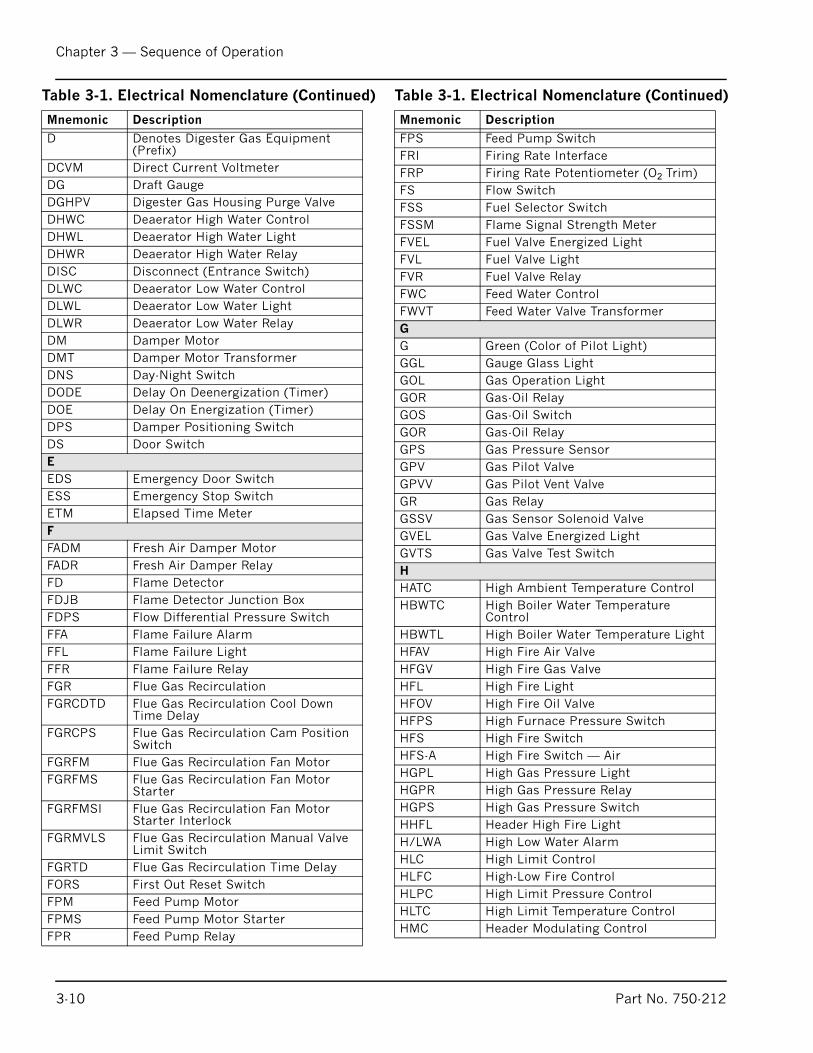
Chapter 3 — Sequence of Operation
D Denotes Digester Gas Equipment (Prefix)
DCVM Direct Current Voltmeter
DG Draft Gauge
DGHPV Digester Gas Housing Purge Valve
DHWC Deaerator High Water Control
DHWL Deaerator High Water Light
DHWR Deaerator High Water Relay
DISC Disconnect (Entrance Switch)
DLWC Deaerator Low Water Control
DLWL Deaerator Low Water Light
DLWR Deaerator Low Water Relay
DM Damper Motor
DMT Damper Motor Transformer
DNS Day-Night Switch
DODE Delay On Deenergization (Timer)
DOE Delay On Energization (Timer)
DPS Damper Positioning Switch
DS Door Switch
E
EDS Emergency Door Switch
ESS Emergency Stop Switch
ETM Elapsed Time Meter
F
FADM Fresh Air Damper Motor
FADR Fresh Air Damper Relay
FD Flame Detector
FDJB Flame Detector Junction Box
FDPS Flow Differential Pressure Switch
FFA Flame Failure Alarm
FFL Flame Failure Light
FFR Flame Failure Relay
FGR Flue Gas Recirculation
FGRCDTD Flue Gas Recirculation Cool Down Time Delay
FGRCPS Flue Gas Recirculation Cam Position Switch
FGRFM Flue Gas Recirculation Fan Motor
FGRFMS Flue Gas Recirculation Fan Motor Starter
FGRFMSI Flue Gas Recirculation Fan Motor Starter Interlock
FGRMVLS Flue Gas Recirculation Manual Valve Limit Switch
FGRTD Flue Gas Recirculation Time Delay
FORS First Out Reset Switch
FPM Feed Pump Motor
FPMS Feed Pump Motor Starter
FPR Feed Pump Relay
Table 3-1. Electrical Nomenclature (Continued)
Mnemonic Description
FPS
FRI
FRP
FS
FSS
FSSM
FVEL
FVL
FVR
FWC
FWV
G
G
GGL
GOL
GOR
GOS
GOR
GPS
GPV
GPV
GR
GSS
GVE
GVT
H
HATC
HBW
HBW
HFAV
HFG
HFL
HFO
HFP
HFS
HFS
HGP
HGP
HGP
HHF
H/LW
HLC
HLFC
HLP
HLTC
HMC
Tabl
Mne
3-10
Feed Pump Switch
Firing Rate Interface
Firing Rate Potentiometer (O2 Trim)
Flow Switch
Fuel Selector Switch
Flame Signal Strength Meter
Fuel Valve Energized Light
Fuel Valve Light
Fuel Valve Relay
Feed Water Control
T Feed Water Valve Transformer
Green (Color of Pilot Light)
Gauge Glass Light
Gas Operation Light
Gas-Oil Relay
Gas-Oil Switch
Gas-Oil Relay
Gas Pressure Sensor
Gas Pilot Valve
V Gas Pilot Vent Valve
Gas Relay
V Gas Sensor Solenoid Valve
L Gas Valve Energized Light
S Gas Valve Test Switch
High Ambient Temperature Control
TC High Boiler Water Temperature Control
TL High Boiler Water Temperature Light
High Fire Air Valve
V High Fire Gas Valve
High Fire Light
V High Fire Oil Valve
S High Furnace Pressure Switch
High Fire Switch
-A High Fire Switch — Air
L High Gas Pressure Light
R High Gas Pressure Relay
S High Gas Pressure Switch
L Header High Fire Light
A High Low Water Alarm
High Limit Control
High-Low Fire Control
C High Limit Pressure Control
High Limit Temperature Control
Header Modulating Control
e 3-1. Electrical Nomenclature (Continued)
monic Description
Part No. 750-212
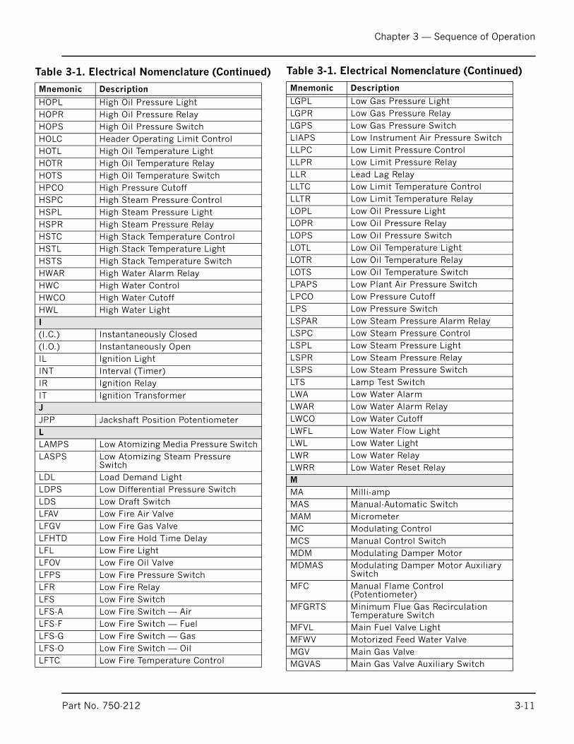
Chapter 3 — Sequence of Operation
HOPL High Oil Pressure Light
HOPR High Oil Pressure Relay
HOPS High Oil Pressure Switch
HOLC Header Operating Limit Control
HOTL High Oil Temperature Light
HOTR High Oil Temperature Relay
HOTS High Oil Temperature Switch
HPCO High Pressure Cutoff
HSPC High Steam Pressure Control
HSPL High Steam Pressure Light
HSPR High Steam Pressure Relay
HSTC High Stack Temperature Control
HSTL High Stack Temperature Light
HSTS High Stack Temperature Switch
HWAR High Water Alarm Relay
HWC High Water Control
HWCO High Water Cutoff
HWL High Water Light
I
(I.C.) Instantaneously Closed
(I.O.) Instantaneously Open
IL Ignition Light
INT Interval (Timer)
IR Ignition Relay
IT Ignition Transformer
J
JPP Jackshaft Position Potentiometer
L
LAMPS Low Atomizing Media Pressure Switch
LASPS Low Atomizing Steam Pressure Switch
LDL Load Demand Light
LDPS Low Differential Pressure Switch
LDS Low Draft Switch
LFAV Low Fire Air Valve
LFGV Low Fire Gas Valve
LFHTD Low Fire Hold Time Delay
LFL Low Fire Light
LFOV Low Fire Oil Valve
LFPS Low Fire Pressure Switch
LFR Low Fire Relay
LFS Low Fire Switch
LFS-A Low Fire Switch — Air
LFS-F Low Fire Switch — Fuel
LFS-G Low Fire Switch — Gas
LFS-O Low Fire Switch — Oil
LFTC Low Fire Temperature Control
Table 3-1. Electrical Nomenclature (Continued)
Mnemonic Description
LGP
LGP
LGP
LIAP
LLP
LLP
LLR
LLTC
LLTR
LOP
LOP
LOP
LOT
LOT
LOT
LPA
LPC
LPS
LSP
LSP
LSP
LSP
LSP
LTS
LWA
LWA
LWC
LWF
LWL
LWR
LWR
M
MA
MAS
MAM
MC
MCS
MDM
MDM
MFC
MFG
MFV
MFW
MGV
MGV
Tabl
Mne
Part No. 750-212
L Low Gas Pressure Light
R Low Gas Pressure Relay
S Low Gas Pressure Switch
S Low Instrument Air Pressure Switch
C Low Limit Pressure Control
R Low Limit Pressure Relay
Lead Lag Relay
Low Limit Temperature Control
Low Limit Temperature Relay
L Low Oil Pressure Light
R Low Oil Pressure Relay
S Low Oil Pressure Switch
L Low Oil Temperature Light
R Low Oil Temperature Relay
S Low Oil Temperature Switch
PS Low Plant Air Pressure Switch
O Low Pressure Cutoff
Low Pressure Switch
AR Low Steam Pressure Alarm Relay
C Low Steam Pressure Control
L Low Steam Pressure Light
R Low Steam Pressure Relay
S Low Steam Pressure Switch
Lamp Test Switch
Low Water Alarm
R Low Water Alarm Relay
O Low Water Cutoff
L Low Water Flow Light
Low Water Light
Low Water Relay
R Low Water Reset Relay
Milli-amp
Manual-Automatic Switch
Micrometer
Modulating Control
Manual Control Switch
Modulating Damper Motor
AS Modulating Damper Motor Auxiliary Switch
Manual Flame Control (Potentiometer)
RTS Minimum Flue Gas Recirculation Temperature Switch
L Main Fuel Valve Light
V Motorized Feed Water Valve
Main Gas Valve
AS Main Gas Valve Auxiliary Switch
e 3-1. Electrical Nomenclature (Continued)
monic Description
3-11
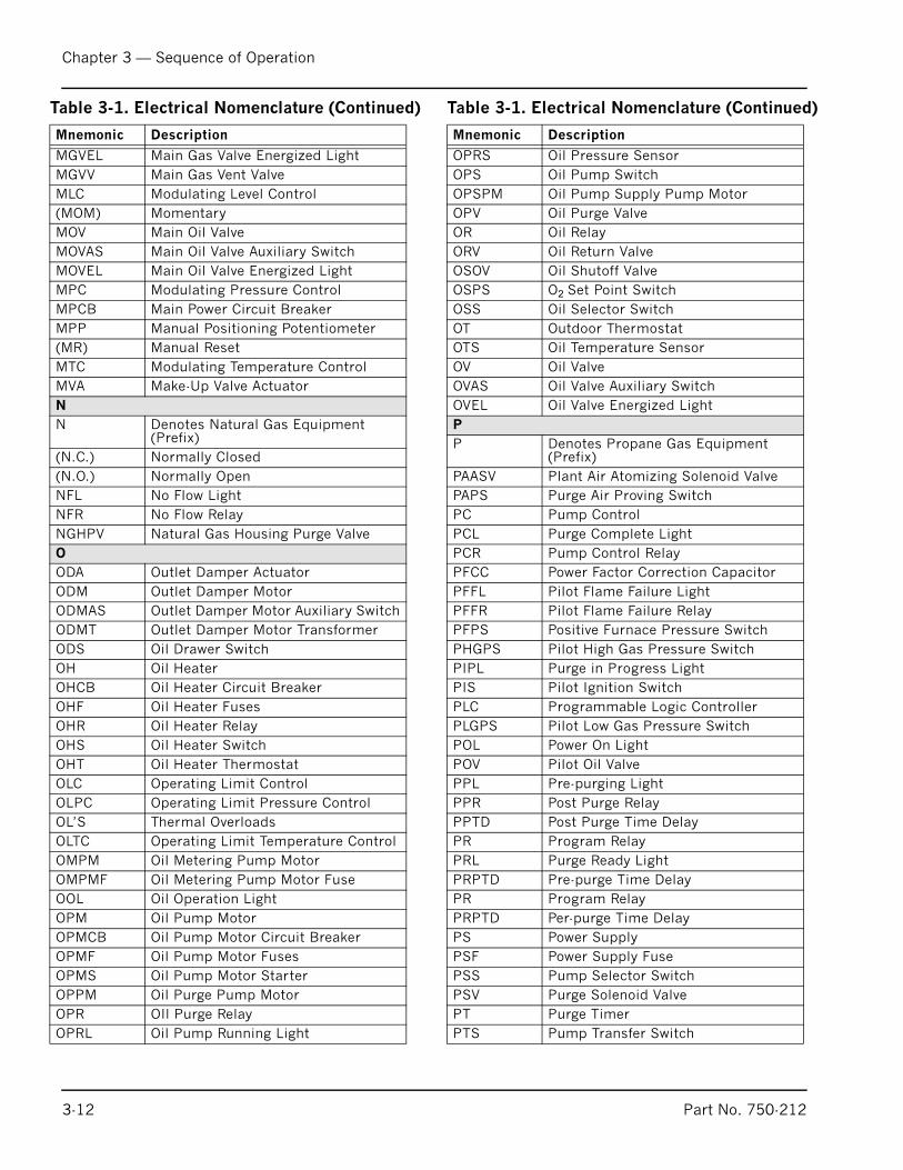
Chapter 3 — Sequence of Operation
MGVEL Main Gas Valve Energized Light
MGVV Main Gas Vent Valve
MLC Modulating Level Control
(MOM) Momentary
MOV Main Oil Valve
MOVAS Main Oil Valve Auxiliary Switch
MOVEL Main Oil Valve Energized Light
MPC Modulating Pressure Control
MPCB Main Power Circuit Breaker
MPP Manual Positioning Potentiometer
(MR) Manual Reset
MTC Modulating Temperature Control
MVA Make-Up Valve Actuator
N
N Denotes Natural Gas Equipment (Prefix)
(N.C.) Normally Closed
(N.O.) Normally Open
NFL No Flow Light
NFR No Flow Relay
NGHPV Natural Gas Housing Purge Valve
O
ODA Outlet Damper Actuator
ODM Outlet Damper Motor
ODMAS Outlet Damper Motor Auxiliary Switch
ODMT Outlet Damper Motor Transformer
ODS Oil Drawer Switch
OH Oil Heater
OHCB Oil Heater Circuit Breaker
OHF Oil Heater Fuses
OHR Oil Heater Relay
OHS Oil Heater Switch
OHT Oil Heater Thermostat
OLC Operating Limit Control
OLPC Operating Limit Pressure Control
OL’S Thermal Overloads
OLTC Operating Limit Temperature Control
OMPM Oil Metering Pump Motor
OMPMF Oil Metering Pump Motor Fuse
OOL Oil Operation Light
OPM Oil Pump Motor
OPMCB Oil Pump Motor Circuit Breaker
OPMF Oil Pump Motor Fuses
OPMS Oil Pump Motor Starter
OPPM Oil Purge Pump Motor
OPR OIl Purge Relay
OPRL Oil Pump Running Light
Table 3-1. Electrical Nomenclature (Continued)
Mnemonic Description
OPR
OPS
OPS
OPV
OR
ORV
OSO
OSP
OSS
OT
OTS
OV
OVA
OVE
P
P
PAA
PAP
PC
PCL
PCR
PFC
PFF
PFF
PFP
PHG
PIP
PIS
PLC
PLG
POL
POV
PPL
PPR
PPT
PR
PRL
PRP
PR
PRP
PS
PSF
PSS
PSV
PT
PTS
Tab
Mne
3-12
S Oil Pressure Sensor
Oil Pump Switch
PM Oil Pump Supply Pump Motor
Oil Purge Valve
Oil Relay
Oil Return Valve
V Oil Shutoff Valve
S O2 Set Point Switch
Oil Selector Switch
Outdoor Thermostat
Oil Temperature Sensor
Oil Valve
S Oil Valve Auxiliary Switch
L Oil Valve Energized Light
Denotes Propane Gas Equipment (Prefix)
SV Plant Air Atomizing Solenoid Valve
S Purge Air Proving Switch
Pump Control
Purge Complete Light
Pump Control Relay
C Power Factor Correction Capacitor
L Pilot Flame Failure Light
R Pilot Flame Failure Relay
S Positive Furnace Pressure Switch
PS Pilot High Gas Pressure Switch
L Purge in Progress Light
Pilot Ignition Switch
Programmable Logic Controller
PS Pilot Low Gas Pressure Switch
Power On Light
Pilot Oil Valve
Pre-purging Light
Post Purge Relay
D Post Purge Time Delay
Program Relay
Purge Ready Light
TD Pre-purge Time Delay
Program Relay
TD Per-purge Time Delay
Power Supply
Power Supply Fuse
Pump Selector Switch
Purge Solenoid Valve
Purge Timer
Pump Transfer Switch
le 3-1. Electrical Nomenclature (Continued)
monic Description
Part No. 750-212
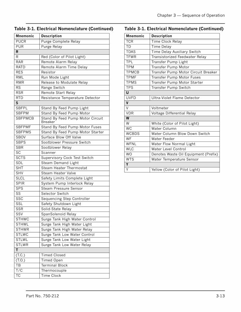
Chapter 3 — Sequence of Operation
PUCR Purge Complete Relay
PUR Purge Relay
R
R Red (Color of Pilot Light)
RAR Remote Alarm Relay
RATD Remote Alarm Time Delay
RES Resistor
RML Run Mode Light
RMR Release to Modulate Relay
RS Range Switch
RSR Remote Start Relay
RTD Resistance Temperature Detector
S
SBFPL Stand By Feed Pump Light
SBFPM Stand By Feed Pump Motor
SBFPMCB Stand By Feed Pump Motor Circuit Breaker
SBFPMF Stand By Feed Pump Motor Fuses
SBFPMS Stand By Feed Pump Motor Starter
SBOV Surface Blow Off Valve
SBPS Sootblower Pressure Switch
SBR Sootblower Relay
SC Scanner
SCTS Supervisory Cock Test Switch
SDL Steam Demand Light
SHT Steam Heater Thermostat
SHV Steam Heater Valve
SLCL Safety Limits Complete Light
SPIR System Pump Interlock Relay
SPS Steam Pressure Sensor
SS Selector Switch
SSC Sequencing Step Controller
SSL Safety Shutdown Light
SSR Solid-State Relay
SSV SpanSolenoid Relay
STHWC Surge Tank High Water Control
STHWL Surge Tank High Water Light
STHWR Surge Tank High Water Relay
STLWC Surge Tank Low Water Control
STLWL Surge Tank Low Water Light
STLWR Surge Tank Low Water Relay
T
(T.C.) Timed Closed
(T.O.) Timed Open
TB Terminal Block
T/C Thermocouple
TC Time Clock
Table 3-1. Electrical Nomenclature (Continued)
Mnemonic Description
TC
TD
TD
TFW
TP
TP
TP
TP
TP
TP
U
UV
V
V
VD
W
W
WC
WC
WF
WF
WL
WO
WT
Y
Y
Tab
Mn
Part No. 750-212
R Time Clock Relay
Time Delay
AS Time Delay Auxiliary Switch
R Transistorized Feedwater Relay
L Transfer Pump Light
M Transfer Pump Motor
MCB Transfer Pump Motor Circuit Breaker
MF Transfer Pump Motor Fuses
MS Transfer Pump Motor Starter
S Transfer Pump Switch
FD Ultra-Violet Flame Detector
Voltmeter
R Voltage Differential Relay
White (Color of Pilot Light)
Water Column
BDS Water Column Blow Down Switch
Water Feeder
NL Water Flow Normal Light
C Water Level Control
Denotes Waste Oil Equipment (Prefix)
S Water Temperature Sensor
Yellow (Color of Pilot Light)
le 3-1. Electrical Nomenclature (Continued)
emonic Description
3-13
Chapter 3 — Sequence of Operation
3-14 Part No. 750-212
Notes:
Milwaukee, Wisconsin
www.cleaver-brooks.com
Chapter 4
Starting and Operating InstructionsProfire H Series
General Preparation for Initial Startup . . . . . . . . . . . . . . . . . . . . . . . . 4-2Startup Procedures . . . . . . . . . . . . . . . . . . . . . . . . . . . . . . . . . . . . . 4-4Burner Adjustments, Single Fuel Natural Gas . . . . . . . . . . . . . . . . . . . 4-7Burner Adjustments, Single Fuel, Oil-fired
(Return Flow Pressure Atomization) . . . . . . . . . . . . . . . . . . . . . . . 4-11Atomizing Air . . . . . . . . . . . . . . . . . . . . . . . . . . . . . . . . . . . . . . . . 4-14Burner Adjustments, Combination Gas and Oil . . . . . . . . . . . . . . . . . 4-18Startup, Operating and Shutdown - All Fuels . . . . . . . . . . . . . . . . . . . 4-22Control Operational Test and Checks . . . . . . . . . . . . . . . . . . . . . . . . 4-24
Chapter 4 — Starting and Operating Instructions Profire H Series
A.GENERAL PREPARATION FOR INITIAL STARTUP
Instructions in Chapter 4 are all based upon installationbeing complete and all electrical, fuel, water and vent stackconnections are made.
The operator should be familiar with the burner, boiler, andall controls and components. To quickly locate and identifythe various controls and components mentioned in thefollowing paragraphs, refer to the illustrations and thecontents of Chapters 1, 2 and 3. Instructions for adjustingmajor components are given in Section C this should bereviewed prior to firing. The wiring diagram should also havebeen studied, along with the firing sequence outlined inChapter 3.
Verify supply of fuel and proper voltage. Check for blownfuses, open circuit breakers, dropped out overloads, etc.Check reset of all starters and controls having manual resetfeatures. Check the lockout switch on the programmer andreset if necessary.
The boiler should be filled with water to the proper operatinglevel using water of ambient temperature. Be sure thattreated feedwater is available and used. In heatingapplications, the entire system should be filled and vented.Refer to Chapter 2 for water requirements. On a steamboiler, open the vent valve to vent air displaced during filling.Leave the vent valve open until the escape of steam is notedafter the burner is operating.
Check all linkage for full and free movement of the damperand metering valves and cams. The check can be done byloosening the linkage at the damper motor connecting armand manipulating the linkage by hand.
Notice
If the boiler is not equipped with
a ProFire burner. Please refer to
the speci f ic Operat ion and
Maintenance manual for the
burner supplied.
! Warning
I t is recommended that the
starting instructions be read
comple te ly un t i l they a re
thoroughly understood, before
attempting to operate the boiler,
rather than performing each
operation as it is read for the first
time. Failure to follow these
instructions could result in
serious personal injury or death.
! Warning
Prior to firing a boiler, be sure
that discharge piping from safety
valves or rel ief valves, and
d ischarge p ip ing f rom a l l
blowdown and drain valves, is
p iped to a SAFE po in t o f
discharge, so that emission of
hot water or s team cannot
possibly cause injury. Failure to
follow these instructions could
result in serious personal injury
or death.
4-2 Part No. 750-212
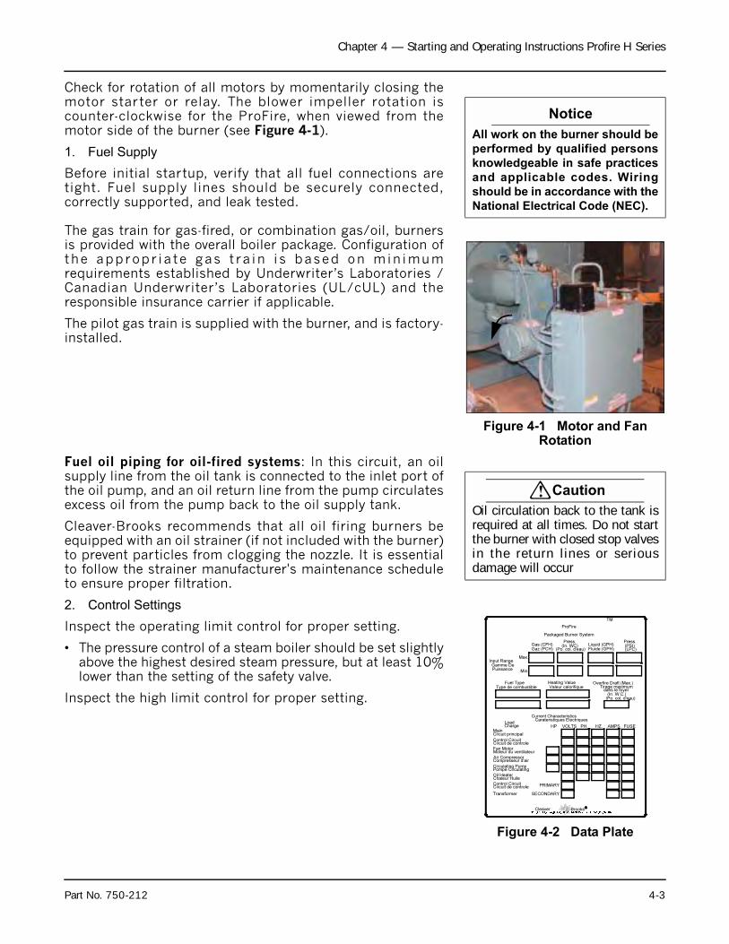
Chapter 4 — Starting and Operating Instructions Profire H Series
Check for rotation of all motors by momentarily closing themotor starter or relay. The blower impeller rotation iscounter-clockwise for the ProFire, when viewed from themotor side of the burner (see Figure 4-1).
1. Fuel Supply
Before initial startup, verify that all fuel connections aretight. Fuel supply lines should be securely connected,correctly supported, and leak tested.
The gas train for gas-fired, or combination gas/oil, burnersis provided with the overall boiler package. Configuration ofthe appropr ia te gas t ra in i s based on min imumrequirements established by Underwriter’s Laboratories /Canadian Underwriter’s Laboratories (UL/cUL) and theresponsible insurance carrier if applicable.
The pilot gas train is supplied with the burner, and is factory-installed.
Fuel oil piping for oil-fired systems: In this circuit, an oilsupply line from the oil tank is connected to the inlet port ofthe oil pump, and an oil return line from the pump circulatesexcess oil from the pump back to the oil supply tank.
Cleaver-Brooks recommends that all oil firing burners beequipped with an oil strainer (if not included with the burner)to prevent particles from clogging the nozzle. It is essentialto follow the strainer manufacturer's maintenance scheduleto ensure proper filtration.
2. Control Settings
Inspect the operating limit control for proper setting.
• The pressure control of a steam boiler should be set slightlyabove the highest desired steam pressure, but at least 10%lower than the setting of the safety valve.
Inspect the high limit control for proper setting.
Notice
All work on the burner should be
performed by qualified persons
knowledgeable in safe practices
and applicable codes. Wiring
should be in accordance with the
National Electrical Code (NEC).
Figure 4-1 Motor and Fan Rotation
! Caution
Oil circulation back to the tank isrequired at all times. Do not startthe burner with closed stop valvesin the return lines or seriousdamage will occur
Figure 4-2 Data Plate
Packaged Burner System
Fan Motor
BrooksMILWAUKEE, WISCONSINDIVISION OF AQUA-CHEM, INC.
R
Air Compressor
Moteur du ventilateur
Compresseur d'air
Cleaver
PH.Main
LoadHP VOLTS
Control Circuit
HZ. AMPS.
Current CharacteristicsCarateristiques Electriques
Charge
Circuit principal
Circuit de controle
(LPC)(PSI)Press.
Liquid (GPH)Fluide (GPH)
Gas (CFH)Gaz (PCH)
Min.
Max.
(Po. col. d'eau)
Press.(In. WC)
Type de combustibleFuel Type Heating Value
Valeur calorifique
Gamme DeInput Range
TM
ProFire
FUSE
Control CircuitCircuit de controle
Transformer
PRIMARY
SECONDARY
(Po. col. d'eau)(In. W.C.)
Overfire Draft (Max.)
dans le foyerTirage maximum
Puissance
Pompe CirculatingCirculating Pump
Chaleur HuileOil Heater
Part No. 750-212 4-3
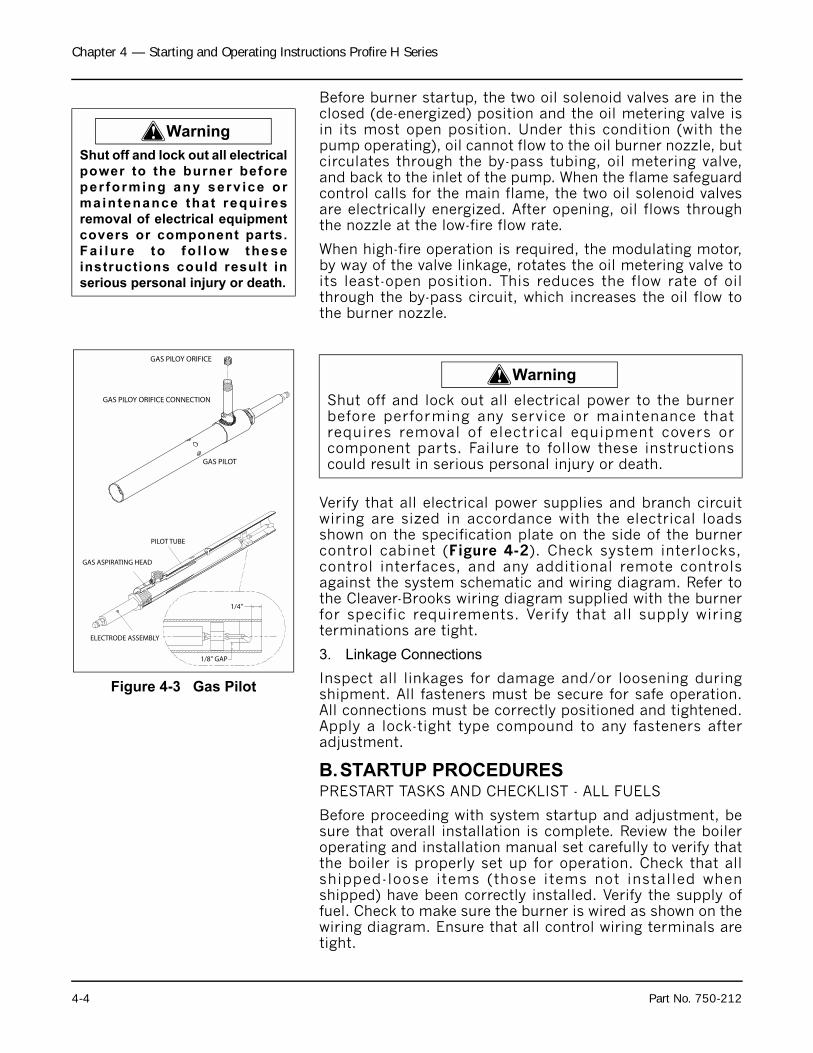
Chapter 4 — Starting and Operating Instructions Profire H Series
Before burner startup, the two oil solenoid valves are in theclosed (de-energized) position and the oil metering valve isin its most open position. Under this condition (with thepump operating), oil cannot flow to the oil burner nozzle, butcirculates through the by-pass tubing, oil metering valve,and back to the inlet of the pump. When the flame safeguardcontrol calls for the main flame, the two oil solenoid valvesare electrically energized. After opening, oil flows throughthe nozzle at the low-fire flow rate.
When high-fire operation is required, the modulating motor,by way of the valve linkage, rotates the oil metering valve toits least-open position. This reduces the flow rate of oilthrough the by-pass circuit, which increases the oil flow tothe burner nozzle.
Verify that all electrical power supplies and branch circuitwiring are sized in accordance with the electrical loadsshown on the specification plate on the side of the burnercontrol cabinet (Figure 4-2). Check system interlocks,control interfaces, and any additional remote controlsagainst the system schematic and wiring diagram. Refer tothe Cleaver-Brooks wiring diagram supplied with the burnerfor specific requirements. Verify that all supply wiringterminations are tight.
3. Linkage Connections
Inspect all linkages for damage and/or loosening duringshipment. All fasteners must be secure for safe operation.All connections must be correctly positioned and tightened.Apply a lock-tight type compound to any fasteners afteradjustment.
B.STARTUP PROCEDURESPRESTART TASKS AND CHECKLIST - ALL FUELS
Before proceeding with system startup and adjustment, besure that overall installation is complete. Review the boileroperating and installation manual set carefully to verify thatthe boiler is properly set up for operation. Check that allshipped-loose items (those items not installed whenshipped) have been correctly installed. Verify the supply offuel. Check to make sure the burner is wired as shown on thewiring diagram. Ensure that all control wiring terminals aretight.
! Warning
Shut off and lock out all electrical
power to the burner before
per forming any serv ice or
maintenance that requi res
removal of electrical equipment
covers or component parts.
Fa i lu re to fo l low these
instructions could result in
serious personal injury or death.
Figure 4-3 Gas Pilot
ELECTRODE ASSEMBLY
PILOT TUBE
GAS ASPIRATING HEAD
1/4"
1/8" GAP
GAS PILOT
GAS PILOY ORIFICE
GAS PILOY ORIFICE CONNECTION
! Warning
Shut off and lock out all electrical power to the burnerbefore performing any service or maintenance thatrequires removal of electrical equipment covers orcomponent parts. Failure to follow these instructionscould result in serious personal injury or death.
4-4 Part No. 750-212

Chapter 4 — Starting and Operating Instructions Profire H Series
Complete the following checklist in preparation for systemstartup:
• Confirm that the fuel and electrical connections have beencompleted in accordance with the applicable codes andinsurance requirements ( i f necessary), and thatconnections comply with the piping schematic and wiringdiagram.
• Check the combustion air fan motor for correct rotationaldirection.
• Check that the boiler is filled with water to the proper level,and that all circulating pumps (hot water units) arecorrectly installed and operational.
• Verify that there is proper gas pressure at the gas train, ifthis is a gas or combination burner. See the burnerspecification plate (Figure 4-2) for minimum and maximumnatural gas pressure requirements.
• For oil burners confirm that the oil tank is adequately filledwith the correct grade of fuel oil, and that any isolationvalves in the supply and return lines are open.
• Check that the flame safeguard has been properly installedinside the control panel.
• Provide the following test equipment on site:
1. Combustion analyzer for O2.2. U-tube manometer, or pressure gauge, to measure gas
pressures (main and pilot).3. Inclined manometer to measure draft pressures.4. Smoke spot tester for oil fired units. CO analyzer for gas
fired burners.5. Voltmeter.6. Thermometers and thermocouples.
AIR AND FUEL CONTROLS (DESCRIPTION)The combustion system air and fuel controls have beenfactory adjusted, and the unit has been test fired before itwas shipped. Regardless of preliminary adjustment andoperation, it is necessary to readjust the controls for localconditions:
• The fuel flow controls must be adjusted to establish therated heat input over the full range of firing-ratemodulation.
• The air controls need to be adjusted, relative to theestablished fuel flow rates, to provide the correct amount ofair for complete, efficient combustion.
Fuel and air adjustments are similar on all ProFire burners,whether gas-fired, oil-fired, or combination gas/oil fired. Thefollowing topics describe air and fuel flow rate adjustments,
! Warning
Attempting initial burner startupwith insufficient knowledge ofthe equipment and star tupprocedures can result in seriousdamage to the equipment. Theoperator must be totally familiarwith the entire startup andadjustment process beforeattempting to operate the burner.Fa i lu re to fo l l ow theseinstructions can result in seriouspersonal injury or death
Part No. 750-212 4-5
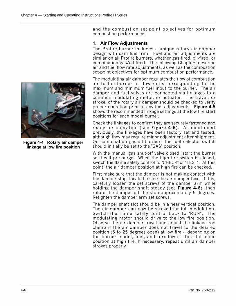
Chapter 4 — Starting and Operating Instructions Profire H Series
and the combustion set-point objectives for optimumcombustion performance:
1. Air Flow Adjustments
The Profire burner includes a unique rotary air damperdesign with cam fuel trim. Fuel and air adjustments aresimilar on all Profire burners, whether gas-fired, oil-fired, orcombination gas/oil fired. The following Chapters describeair and fuel flow rate adjustments, as well as the combustionset-point objectives for optimum combustion performance.
The modulating air damper regulates the flow of combustionair to the burner at f low rates corresponding to themaximum and minimum fuel input to the burner. The airdamper and fuel valves are connected via linkages to acommon modulating motor, or actuator. The travel, orstroke, of the rotary air damper should be checked to verifyproper operation prior to any fuel adjustments. Figure 4-5shows the recommended linkage settings at the low fire startpositions for each model burner.
Check the linkages to confirm they are securely fastened andready for operation (see Figure 4-6). As mentionedpreviously, the linkages have been factory set and tested,although they may require minor adjustment after shipment.On combination gas-oil burners, the fuel selector switchshould initially be set to the "GAS" position.
With the manual gas shut-off valve closed, start the burnerso it will pre-purge. When the high fire switch is closed,switch the flame safety control to "CHECK" or "TEST". At thispoint, the air damper position at high fire can be checked.
First make sure that the damper is not making contact withthe damper stop, located inside the air damper box. If it is,carefully loosen the set screws of the damper arm whileholding the damper shaft steady (see Figure 4-6), thenrotate the damper off the stop approximately 5 degrees.Retighten the damper arm set screws.
The damper shaft slot should be in a near vertical position.The air damper can now be stroked for full modulation.Switch the f lame safety control back to "RUN". Themodulating motor should drive to the low fire position.Observe the air damper travel and adjust the linkage rodclamp if the air damper does not travel to the desiredposition (5 to 25 degrees open) at low fire -- depending onthe burner model, fuel, and turndown -- to a full openposition at high fire. If necessary, repeat until air damperstrokes properly.
Figure 4-4 Rotary air damper linkage at low fire position
4-6 Part No. 750-212
Chapter 4 — Starting and Operating Instructions Profire H Series
2. Combustion Settings
Fuel and air flow rates are individually adjusted at low fire,at high fire, and at each intermediate cam screw position toachieve rated heat input, firing rate turndown, optimumefficiency, safe operation, and the ability to cope withenvironmental changes (including air temperature,humidity, barometric pressure,) and fuel property changes.Adjustments may be required to meet certain environmentalemissions criteria, such as NOx or CO. Combustionadjustments also vary with specific system applications.
Turndown capability for oil is typically less than that fornatural gas. Therefore, on combination fueled burners, gasturndown performance may be restricted (or determined) bythe excess air levels set initially for oil combustion.
Two key components residing in flue gas are used tooptimize combustion efficiency; excess air and unburnedfuel. The system should be adjusted to the minimum excessair quantity that provides low levels of unburned fuel withsuf f ic ient remain ing oxygen to cope wi th normalatmospheric and fuel related changes. Unburned fuel ismeasured as carbon monoxide (CO) when burning naturalgas, and smoke spots when burning oil.
ProFire burners are capable of operating at CO levels of lessthan 50 ppm at all firing rates when firing natural gas. Theburner should be set-up and maintained to yield smoke spotlevels less than a #2 spot (ASTM D2156 Shell-BacharachScale) to minimize soot build-up in the boiler when firing #2oil.
C.BURNER ADJUSTMENTS, SINGLE FUEL NATURAL GAS
Note: The operator must consider and allow for normalvariations in air and fuel, which would reduce the rangeof excessive oxygen in the flue gas accordingly.
Notice
The low fire position will befine-tuned during combustionstart-up.
Part No. 750-212 4-7
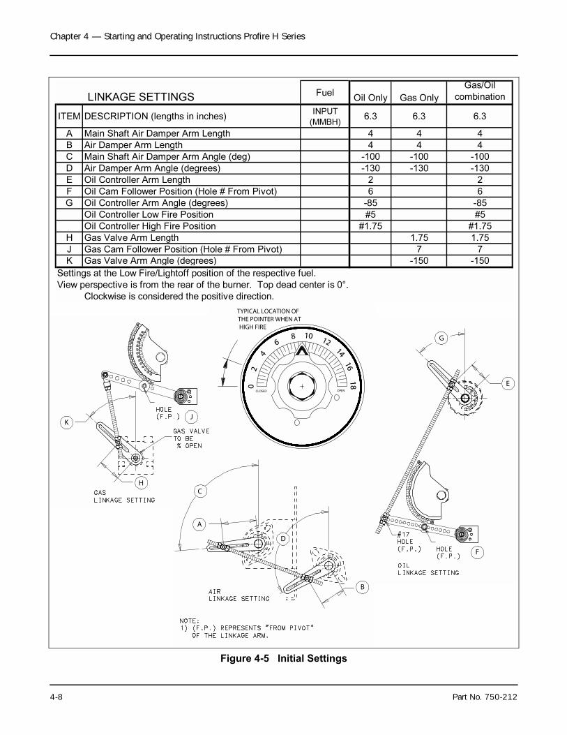
Chapter 4 — Starting and Operating Instructions Profire H Series
Figure 4-5 Initial Settings
TYPICAL LOCATION OFTHE POINTER WHEN ATHIGH FIRE
OPENCLOSED
16
14
12108
6
42
0
18
KJ
H
A
C
D
B
G
E
F
LINKAGE SETTINGSFuel
Oil Only Gas Only
Gas/Oil
combination
ITEM DESCRIPTION (lengths in inches)INPUT
(MMBH)6.3 6.3 6.3
A Main Shaft Air Damper Arm Length 4 4 4
B Air Damper Arm Length 4 4 4
C Main Shaft Air Damper Arm Angle (deg) -100 -100 -100
D Air Damper Arm Angle (degrees) -130 -130 -130
E Oil Controller Arm Length 2 2
F Oil Cam Follower Position (Hole # From Pivot) 6 6
G Oil Controller Arm Angle (degrees) -85 -85
Oil Controller Low Fire Position #5 #5
Oil Controller High Fire Position #1.75 #1.75
H Gas Valve Arm Length 1.75 1.75
J Gas Cam Follower Position (Hole # From Pivot) 7 7
K Gas Valve Arm Angle (degrees) -150 -150
Settings at the Low Fire/Lightoff position of the respective fuel.
View perspective is from the rear of the burner. Top dead center is 0°.
Clockwise is considered the positive direction.
4-8 Part No. 750-212
Chapter 4 — Starting and Operating Instructions Profire H Series
Note: This Chapter provides detailed procedures for setupand adjustment of a gas-fired combustion system.Similar discussions are also presented in this chapterfor startup and adjustment of oil-fired and combination-fueled gas or oil systems.
These procedures assume that the pre-startup tasks,checklists, and adjustments have been completed, and thatthe boiler system is prepared for initial star tup. Allnecessary test equipment, should be available on site andinstalled.
CONTROLS SETUP. Complete the following burner systemcontrol setup steps before beginning the natural gas startupprocedure:
1. Check the linkages to confirm they are securely fastened and ready for operation (Figure 4-5)
2. Set the burner switch in the "OFF" position.3. Place the Manual/Auto mode switch to the "MANUAL"
position.4. Adjust the manual flame control to the "CLOSED" (or low
fire) position.
5. Verify that the gas valve cam trim and linkage assembly isclose to the settings listed in Figure 4-5. Check that thecam follower, linkage and gas valve arm are in the properpositions and properly tightened. The slot in the gasvalve shaft should be 5 to 10% open at the low fireposition.
STARTUP. Proceed with startup of the natural gas-firedsystem as follows:
1. Close the downstream manual shut-off valve of the burner gas train.
2. Turn on electrical power for the burner, boiler, and relatedcomponents.
3. Place the upstream manual gas valve in the on position,allowing natural gas to enter the gas train. (furthest fromthe burner). Reset Low Gas Pressure Switch ( i fapplicable).
4. Verify that the gas metering valve is nearly closed.5. Turn the burner switch on. This will start the combustion
air fan motor and initiate the pre-purge sequence.Observe the travel of the gas valve. The valve should benearly full open at the high fire position. If necessary,adjust the gas valve linkage rod clamp setting.
6. When the prepurge sequence ends, the pilot valve willopen. The pilot flame should be visible from the viewingwindow.
7. When the pilot is established, the flame safeguard willenergize the main gas valve (this is accompanied by fuelvalve activity and illumination of the FUEL VALVE light).The main gas valve should be visually checked by
! Warning
Attempting initial burner startupwith insufficient knowledge ofthe equipment and s tar tupprocedures can result in seriousdamage to the equipment. Theoperator must be totally familiarwith the ent i re star tup andad jus tment p rocess be fo reattempting to operate the burner.Fa i l u r e t o f o l l ow theseinstructions can result in seriouspersonal injury or death
Notice
The l inkages have beenfac tory -se t and tes ted ,although they may requiref ine ad justment for thespecific application. If thelinkage is not in place, or ifthe setting has been lost,ins ta l l the l inkage inaccordance with Figure 5-9.
Notice
For initial boiler startup, thedownstream manual gasshutoff valve should be in theclosed position to ensureproper operat ion of theautomatic gas valves. Thisvalve can then be slowlyopened when the pilot isestablished and proven.
Part No. 750-212 4-9
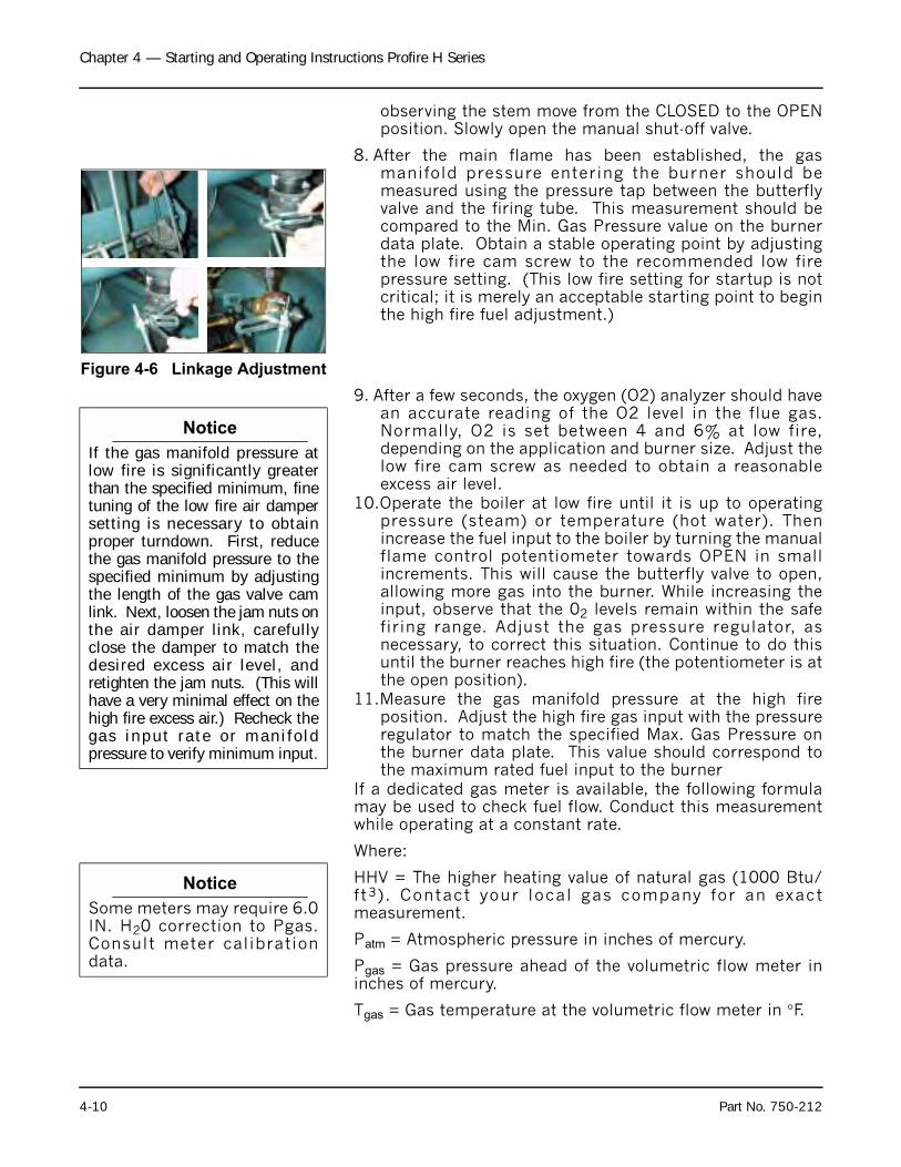
Chapter 4 — Starting and Operating Instructions Profire H Series
observing the stem move from the CLOSED to the OPENposition. Slowly open the manual shut-off valve.
8. After the main flame has been established, the gasmanifold pressure entering the burner should bemeasured using the pressure tap between the butterflyvalve and the firing tube. This measurement should becompared to the Min. Gas Pressure value on the burnerdata plate. Obtain a stable operating point by adjustingthe low fire cam screw to the recommended low firepressure setting. (This low fire setting for startup is notcritical; it is merely an acceptable starting point to beginthe high fire fuel adjustment.)
9. After a few seconds, the oxygen (O2) analyzer should havean accurate reading of the O2 level in the flue gas.Normally, O2 is set between 4 and 6% at low fire,depending on the application and burner size. Adjust thelow fire cam screw as needed to obtain a reasonableexcess air level.
10.Operate the boiler at low fire until it is up to operatingpressure (steam) or temperature (hot water). Thenincrease the fuel input to the boiler by turning the manualflame control potentiometer towards OPEN in smallincrements. This will cause the butterfly valve to open,allowing more gas into the burner. While increasing theinput, observe that the 02 levels remain within the safefiring range. Adjust the gas pressure regulator, asnecessary, to correct this situation. Continue to do thisuntil the burner reaches high fire (the potentiometer is atthe open position).
11.Measure the gas manifold pressure at the high fireposition. Adjust the high fire gas input with the pressureregulator to match the specified Max. Gas Pressure onthe burner data plate. This value should correspond tothe maximum rated fuel input to the burner
If a dedicated gas meter is available, the following formulamay be used to check fuel flow. Conduct this measurementwhile operating at a constant rate.
Where:
HHV = The higher heating value of natural gas (1000 Btu/ft3) . Contact your local gas company for an exactmeasurement.
Patm = Atmospheric pressure in inches of mercury.
Pgas = Gas pressure ahead of the volumetric flow meter ininches of mercury.
Tgas = Gas temperature at the volumetric flow meter in °F.
Figure 4-6 Linkage Adjustment
Notice
If the gas manifold pressure atlow fire is significantly greaterthan the specified minimum, finetuning of the low fire air dampersetting is necessary to obtainproper turndown. First, reducethe gas manifold pressure to thespecified minimum by adjustingthe length of the gas valve camlink. Next, loosen the jam nuts onthe air damper link, carefullyclose the damper to match thedesired excess air level, andretighten the jam nuts. (This willhave a very minimal effect on thehigh fire excess air.) Recheck thegas input ra te o r man i fo ldpressure to verify minimum input.
Notice
Some meters may require 6.0IN. H20 correction to Pgas.Consult meter calibrationdata.
4-10 Part No. 750-212
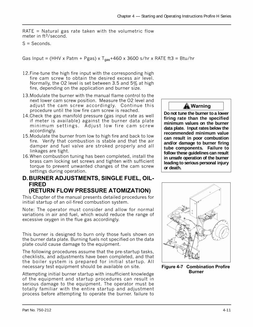
Chapter 4 — Starting and Operating Instructions Profire H Series
RATE = Natural gas rate taken with the volumetric flowmeter in ft3/second.
S = Seconds.
Gas Input = (HHV x Patm + Pgas) x Tgas+460 x 3600 s/hr x RATE ft3 = Btu/hr
12.Fine-tune the high fire input with the corresponding highfire cam screw to obtain the desired excess air level.Normally, the O2 level is set between 3.5 and 5% at highfire, depending on the application and burner size.
13.Modulate the burner with the manual flame control to thenext lower cam screw position. Measure the O2 level andadjust the cam screw accordingly. Continue thisprocedure until the low fire cam screw is reached.
14.Check the gas manifold pressure (gas input rate as wellif meter is available) against the burner data plateminimum sett ings. Adjust low f i re cam screwaccordingly.
15.Modulate the burner from low to high fire and back to lowfire. Verify that combustion is stable and that the airdamper and fuel valve are stroked properly and alllinkages are tight.
16.When combustion tuning has been completed, install thebrass cam locking set screws and tighten with sufficienttorque to prevent unwanted changes of the cam screwsettings during operation.
D.BURNER ADJUSTMENTS, SINGLE FUEL, OIL-FIRED(RETURN FLOW PRESSURE ATOMIZATION)
This Chapter of the manual presents detailed procedures forinitial startup of an oil-fired combustion system.
Note: The operator must consider and allow for normalvariations in air and fuel, which would reduce the range ofexcessive oxygen in the flue gas accordingly.
This burner is designed to burn only those fuels shown onthe burner data plate. Burning fuels not specified on the dataplate could cause damage to the equipment.
The following procedures assume that the pre-startup tasks,checklists, and adjustments have been completed, and thatthe boiler system is prepared for initial star tup. Allnecessary test equipment should be available on site.
Attempting initial burner startup with insufficient knowledgeof the equipment and startup procedures can result inserious damage to the equipment. The operator must betotally familiar with the entire startup and adjustmentprocess before attempting to operate the burner. failure to
! Warning
Do not tune the burner to a lowerfiring rate than the specifiedminimum values on the burnerdata plate. Input rates below therecommended minimum valuecan result in poor combustionand/or damage to burner firingtube components. Failure tofollow these guidelines can resultin unsafe operation of the burnerleading to serious personal injuryor death.
Figure 4-7 Combination Profire Burner
Part No. 750-212 4-11
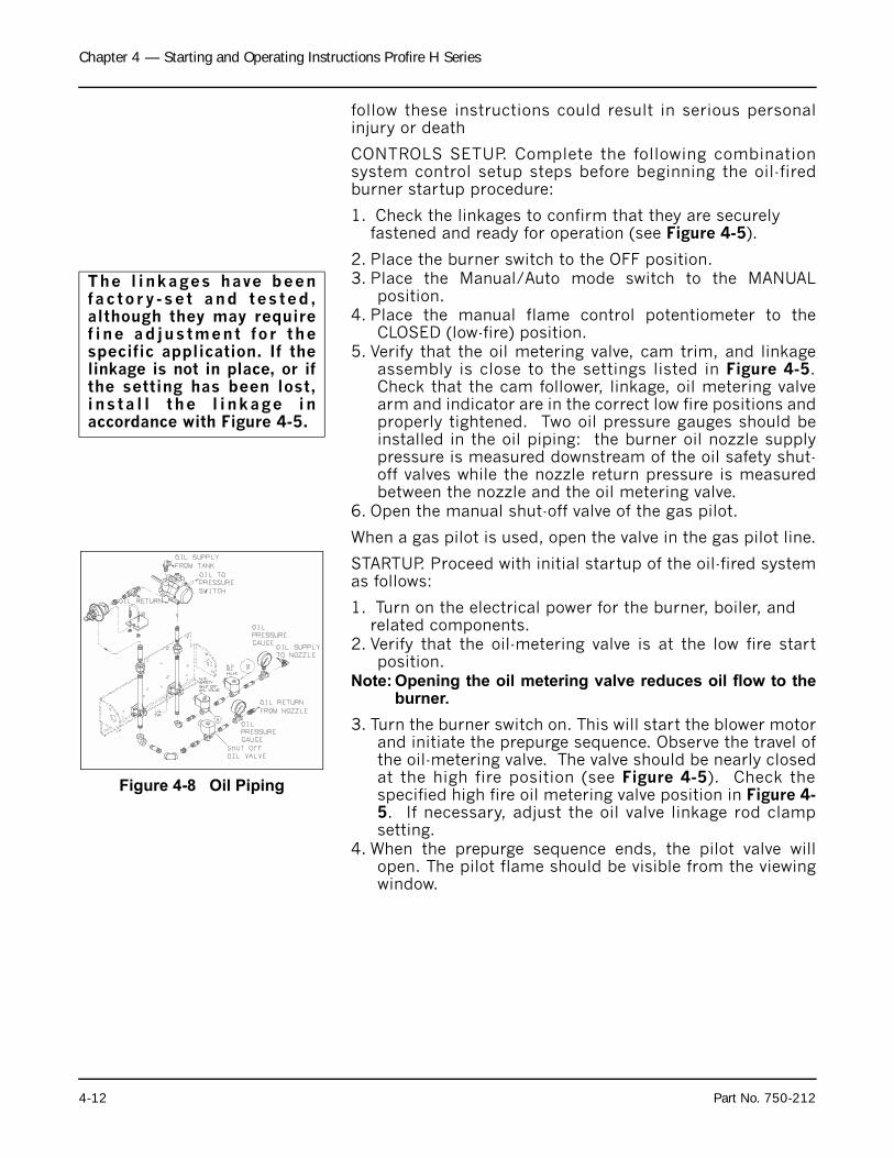
Chapter 4 — Starting and Operating Instructions Profire H Series
follow these instructions could result in serious personalinjury or death
CONTROLS SETUP. Complete the following combinationsystem control setup steps before beginning the oil-firedburner startup procedure:
1. Check the linkages to confirm that they are securely fastened and ready for operation (see Figure 4-5).
2. Place the burner switch to the OFF position.3. Place the Manual/Auto mode switch to the MANUAL
position.4. Place the manual flame control potentiometer to the
CLOSED (low-fire) position.5. Verify that the oil metering valve, cam trim, and linkage
assembly is close to the settings listed in Figure 4-5.Check that the cam follower, linkage, oil metering valvearm and indicator are in the correct low fire positions andproperly tightened. Two oil pressure gauges should beinstalled in the oil piping: the burner oil nozzle supplypressure is measured downstream of the oil safety shut-off valves while the nozzle return pressure is measuredbetween the nozzle and the oil metering valve.
6. Open the manual shut-off valve of the gas pilot.
When a gas pilot is used, open the valve in the gas pilot line.
STARTUP. Proceed with initial startup of the oil-fired systemas follows:
1. Turn on the electrical power for the burner, boiler, and related components.
2. Verify that the oil-metering valve is at the low fire startposition.
Note: Opening the oil metering valve reduces oil flow to theburner.
3. Turn the burner switch on. This will start the blower motorand initiate the prepurge sequence. Observe the travel ofthe oil-metering valve. The valve should be nearly closedat the high fire position (see Figure 4-5). Check thespecified high fire oil metering valve position in Figure 4-5. If necessary, adjust the oil valve linkage rod clampsetting.
4. When the prepurge sequence ends, the pilot valve willopen. The pilot flame should be visible from the viewingwindow.
The l inkages have beenfac tory -se t and tes ted ,although they may requiref ine ad justment for thespecific application. If thelinkage is not in place, or ifthe setting has been lost,ins ta l l the l inkage inaccordance with Figure 4-5.
Figure 4-8 Oil Piping
4-12 Part No. 750-212
Chapter 4 — Starting and Operating Instructions Profire H Series
5. After the main flame has been established, the oilpressures entering and returning from the burner nozzleshould be measured. On return flow pressure atomizedoil systems, the supply pressure should remain relativelyconstant from low fire to high fire, normally between 270and 300 psi. (The oil pump is factory set at 300 psi. Ifnecessary, oil pump supply pressure can be adjustedwith the pump's internal pressure regulating screw.)
6. The low fire return pressure should match the Min. OilPressure specified on the burner data plate (between 40- 100 psi). For fine-tuning, change the oil metering valveposition by adjusting the low fire cam screw. If thepressure is significantly off, adjust the length of the oilcam linkage rod to correct the low fire position of oilmetering valve. Adequate excess air should also beverified with an oxygen analyzer. Normally, O2 is setbetween 4 and 6% at low fire, depending on theapplication and burner size.
7. Operate at low fire until it is thoroughly warmed. Then,one cam screw at a time, modulate to high fire with themanual flame control. This will cause the oil meteringvalve to close, resulting in an increase in the return lineoil pressure. Check the excess air in the flue gas whilemodulating to high fire (maintain O2 levels between 4 -6%). Make cam screw adjustments as needed tomaintain adequate excess air.
8. Verify that the high fire supply pressure stays between280 to 300 psi. (The oil pump is factory set at 300 psi.If necessary, oil pump supply pressure can be adjustedwith the pump's internal pressure regulating screw.)
9. Set the high fire oil return pressure to match the specifiedburner data plate Max. Oil Pressure setting (usually inthe range o f 160 - 220 ps i ) by ad jus t ing thecorresponding cam screw to open or close the oil-metering valve, as necessary.
10.Check the high fire excess air level. Normally, the O2level is set between 3.5 and 5% at high fire, dependingon the application and burner size
11.Modulate the burner with the manual flame control to thenext lower cam screw position. Measure the O2 level atintermediate screw positions and adjust each cam screwto maintain between 3.5 to 5%. Continue this procedureuntil the low fire cam screw is reached.
12.Verify that the low fire return oil pressure is at the burnerdata plate specified minimum pressure. Excess air levelshould be set between 4 to 6% O2. Fine tune byadjusting the low fire cam screw accordingly.
13.Following combustion setup, tighten all linkages. Checkfor smooth light off by cycling the burner through the pre-purge sequence again. During pre-purge, verify that alllinkages, dampers and valves operate smoothly withoutinterference or binding. Verify that the pilot flame issufficient and the burner lights off smoothly.
Notice
If the pilot is established, theflame safeguard will energizethe two oil solenoid valves(this is accompanied by aclick from the solenoid valvesand illumination of the FUELVALVE l ight ) and the o i lburner should ignite on low-fire.
Notice
If the excess air significantlydeviates from the recommendedO2 level after making the properlow fire oil valve adjustment, finetuning of the low fire air dampersetting is necessary to obtainproper turndown. Loosen the jamnuts on the air damper link,carefully adjust the damper tomatch the desired excess airlevel, and retighten the jam nuts.(This will have a very minimaleffect on the high fire excess air.)Recheck the low fire oil returnpressure to verify minimum input.
Part No. 750-212 4-13
Chapter 4 — Starting and Operating Instructions Profire H Series
14.Modulate and recheck combustion air at different firingrate positions. Smoke spot measurements should be lessthan a No. 2 (Bacharach).
15.When combustion tuning has been completed, install thebrass cam locking set screws and tighten with sufficienttorque to prevent unwanted changes of the cam screwsettings during operation.
E. ATOMIZING AIRThis Chapter of the manual presents detailed procedures forstart-up on oil fired air atomizing system. Burners areavailable with a burner mounted oil pump or remote oilpump. (Refer to Figure 4-9 and Figure 4-10)
Notice
Burner input can be verified withthe use of oil meters in the supplyand return lines from the burnernozzle. The flow rate measured inthe return line must be subtractedfrom the flow rate measured inthe supply line. Following start-up, it is strongly recommendedthat the flow meters be removedfrom the system.
4-14 Part No. 750-212
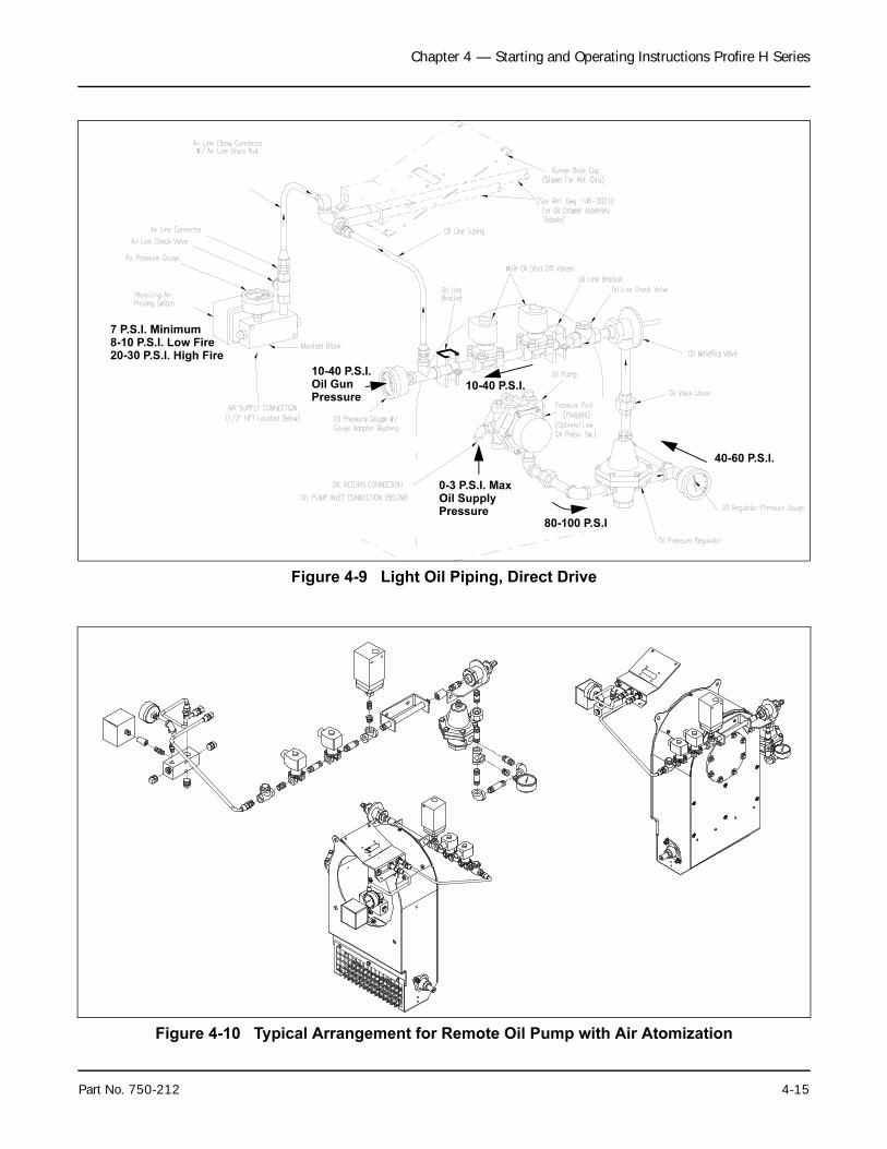
Chapter 4 — Starting and Operating Instructions Profire H Series
Figure 4-9 Light Oil Piping, Direct Drive
Figure 4-10 Typical Arrangement for Remote Oil Pump with Air Atomization
0-3 P.S.I. Max
80-100 P.S.I
40-60 P.S.I.
10-40 P.S.I.
10-40 P.S.I.Oil GunPressure
Oil SupplyPressure
7 P.S.I. Minimum8-10 P.S.I. Low Fire20-30 P.S.I. High Fire
Part No. 750-212 4-15
Chapter 4 — Starting and Operating Instructions Profire H Series
1. The supply and pressure of the atomizing air on an oil-firedburner should be checked. Before starting, inspect the oilpump lube oil level. Add oil if necessary to bring the level tothe mid-point or slightly higher of the sight glass. Use SAE 20detergent oil.
2. To verify air flow and pressure, place the burner Run/testSwitch on the program relay to the test position. If the burneris a combination fuel burner, be sure that the gas/oil selectorswitch is set to “oil.” Turn the Burner Switch on. The burnerwill cycle to the low fire pre-purge position and stop there.Observe the reading on the air pressure gauge (Figure 4-9).With no oil flow, the pressure should be a minimum of 7 psi.
If there is no pressure, determine the cause and correct itbefore proceeding. Check for obstructions in the air inlet line,incorrect rotation, or a loose oil nozzle or other leaks. If thepressure is much higher without any oil flow, check forobstruction in the discharge line or at the oil nozzle. If there isno obstruction, restrict the air flow by adjusting the air intakevalve screw.The air pressure will increase when an oil flow exists. At lowfiring rate, the air pressure may rise to 8 psi or more.
Note: Abnormally high pressure indicated on the nozzle airpressure gauge is an indication that the burner nozzlehas become clogged. In the event of clogging, checkthe nozzle and clean as necessary.
After air flow has been verified, turn the burner switch offand return the run/test switch to the run position.
3. Prior to initial firing, oil flow and pressure should beestablished and verified. Atomizing air pressure should alsobe established as outlined above.
If the burner is a combination fuel model, be certain that theMain Gas Shutoff Cock is closed and set the Gas/oilSelector Switch to “oil.”
Oil Flow - Open all valves in the oil suction and oil returnlines.
If the oil supply tank is located above the level of the pumpand flow to the pump is by gravity, then it will usually benecessary to vent the suction line to allow oil to fill the line.Venting the suction line can generally be accomplished bycracking a union fitting, or by opening the cap of the oilstrainer using care to prevent spillage of oil. Tighten thefitting or the cap as soon as oil flow appears.
If the oil supply tank is below the level of the oil pump, it isMANDATORY that the suction l ine to the pump becompletely filled with oil prior to starting the pump to avoidthe possibility of damage to the pump gears. Non-lubricatingfluids such as kerosene should not be used for priming.
! Caution
The air pressure should notexceed 30 psi at high fire.Greater air pressure causesexcessive wear of the airpump, increases lube oilusage, and can overload themotor, thus causing damageto the equipment.
4-16 Part No. 750-212
Chapter 4 — Starting and Operating Instructions Profire H Series
Prior to priming the suction line and the initial start, checkto make certain that all plugs, connections, etc., have beensecurely tightened to prevent leaks.
A standard equipped boi ler has a selector switchincorporated in the oil pump motor starter. Momentarilyenergize the starter to check for proper pump rotation. Withthe rotation verified, operate the pump to determine that oilcirculation exists. Observe the regulated oil pressure gaugefor indication that flow is established. If no pressure showson the gauge after a few moments, stop the oil pump and re-prime. If the supply tank is lower than the pump, it ispossible that the initial priming of the suction line, followedby operation of the pump, will not establish oil flow. Thismight be caused by obstruction in the suction line, excessivelift, inadequate priming, suction line leaks, etc. If oil flow isnot readily established, avoid prolonged operation of thepump to minimize risk of damage to internal parts of thepump. If oil flow is not established after a second or thirdpriming attempt, a full investigation is required todetermine the cause.
A vacuum (or a compound pressure-vacuum) gauge shouldbe installed at the suction port of the pump and its readingobserved and recorded for future guidance. If a vacuumcondition exists, the reading will reveal the tightness of thesystem. It is advisable to maintain the vacuum reading atless than 10" Hg. A vacuum in excess of 10" Hg. may allowoil to vaporize, causing cavitation, loss of prime, andunstable firing condition.
4. Oil Pressure - For burner mounted oil pumps supplypressure is 3 to 5 psi at the inlet of the oil pump. For remote oil pump systems oil supply pressure is 75 to 50psi at inlet of pressure regulator.
The pressure regulator needs to be adjusted to obtainapproximately 21 psi. on the nozzle line pressure gauge atmaximum firing rate.
When oil is supplied from a pressurized loop to a multipleboiler installation, the relief valve in the loop should beproperly adjusted to provide this reading. In thiscircumstance, the relief valve at the terminal block should beadjusted to the point when it will be inoperative (or removedand openings plugged). To render inoperative, turn theadjusting screw in as far as possible.
Atomizing air pressure will vary from 8 psi on low fire to 20psi on high fire. The pressure gauge will indicate a higherreading when the flame is present and will increase as thefiring rate increases. After the burner is firing and when theair pump is running, final adjustment can be made at the aircompressor.
O2 readings shall be approximately 6% at low fire and 4% athigh fire.
Part No. 750-212 4-17
Chapter 4 — Starting and Operating Instructions Profire H Series
F. BURNER ADJUSTMENTS, COMBINATION GAS AND OIL
Note: The operator must consider and allow for normalvariations in air and fuel, which would reduce the rangeof excessive oxygen in the flue gas accordingly.
This Chapter of the manual presents procedures to befollowed for initial startup of a combination ProFire burner.
These procedures assume that the pre-startup tasks,checklists, and adjustments have been completed, and thatthe boiler system is prepared for initial star tup. Allnecessary test equipment should be available on site.
In general, the combination fueled system is to be startedfirst using oil, because, as a fuel, oil has a greatercombustion air requirement than natural gas. After beingcompletely adjusted for oil combustion, the burner is re-started and adjusted using natural gas as fuel. Combustionadjustment of the combination burner for natural gasinvolves balancing the input gas rates only against theexisting flow of combustion air, as established initially foroil-firing. Do not readjust the air damper setting when tuningthe combination burner for combustion of natural gas.
CONTROLS SETUP. Complete the following system controlsetup steps before beginning the combination burnerstartup procedure:
1. Check the linkages to confirm that they are securely fastened and ready for operation.
NOTE: The linkages have been factory-set and tested,although they may require fine tuning for the specificapplication. If the linkage is not in place, or if the setting hasbeen lost, install the linkage in accordance with Figure 4-5.
2. Place the burner switch in the OFF position.3. Place the Modulating Mode switch in the MANUAL
position.4. Place the manual flame potentiometer in the CLOSE (low-
fire) position.5. Verify that the oil metering valve, gas valve, cam trim and
associated linkage assemblies are close to the settingslisted in Figure 4-5. Check that the cam followers,linkages, valve arms and indicators are in the correct lowfire positions and properly tightened. Two oil pressuregauges should be installed in the oil piping: the burneroil nozzle supply pressure is measured downstream ofthe oil safety shut-off valves while the nozzle returnpressure is measured between the nozzle and the oilmetering valve. The slot in the gas valve shaft should be5 to 10% open at the low fire position.
6. Open the manual shut-off valve of the gas pilot.
STARTUP. Proceed with initial startup using oil as follows:
! Caution
This burner is designed toburn only those fuels shownon the burner data plate.Burning fuels not specified onthe data plate could causedamage to the equipment.
! Warning
Attempting initial burnerstar tup with insuf f ic ientknowledge of the equipmentand startup procedures canresult in serious damage. Theoperator must be total lyfami l i a r w i th the en t i res tar tup and ad jus tmentprocess before attempting tooperate the burner.
4-18 Part No. 750-212
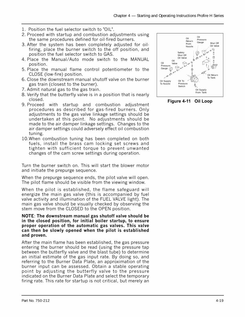
Chapter 4 — Starting and Operating Instructions Profire H Series
1. Position the fuel selector switch to "OIL".2. Proceed with startup and combustion adjustments using
the same procedures defined for oil-fired burners.3. After the system has been completely adjusted for oil-
firing, place the burner switch to the off position, andposition the fuel selector switch to GAS.
4. Place the Manual/Auto mode switch to the MANUALposition.
5. Place the manual flame control potentiometer to theCLOSE (low-fire) position.
6. Close the downstream manual shutoff valve on the burnergas train (closest to the burner).
7. Admit natural gas to the gas train.8. Verify that the butterfly valve is in a position that is nearly
closed.9. Proceed with startup and combustion adjustment
procedures as described for gas-fired burners. Onlyadjustments to the gas valve linkage settings should beundertaken at this point. No adjustments should bemade to the air damper linkage settings. Changes to theair damper settings could adversely effect oil combustiontuning.
10.When combustion tuning has been completed on bothfuels, install the brass cam locking set screws andtighten with sufficient torque to prevent unwantedchanges of the cam screw settings during operation.
Turn the burner switch on. This will start the blower motorand initiate the prepurge sequence.
When the prepurge sequence ends, the pilot valve will open.The pilot flame should be visible from the viewing window.
When the pilot is established, the flame safeguard willenergize the main gas valve (this is accompanied by fuelvalve activity and illumination of the FUEL VALVE light). Themain gas valve should be visually checked by observing thestem move from the CLOSED to the OPEN position.
NOTE: The downstream manual gas shutoff valve should bein the closed position, for initial boiler startup, to ensureproper operation of the automatic gas valves. This valvecan then be slowly opened when the pilot is establishedand proven.
After the main flame has been established, the gas pressureentering the burner should be read (using the pressure tapbetween the butterfly valve and the blast tube) to determinean initial estimate of the gas input rate. By doing so, andreferring to the Burner Data Plate, an approximation of theburner input can be assessed. Obtain a stable operatingpoint by adjusting the butterfly valve to the pressureindicated on the Burner Data Plate and select the temporaryfiring rate. This rate for startup is not critical, but merely an
Figure 4-11 Oil Loop
OilPressureGauge
OilValve
SafetyShut OffOil Valve
OilReturnFromNozzle
OilPressureGauge Shut Off
Oil Valve
Oil ReturnTo Tank
Oil SupplyFrom Tank
Oil ToPressureSwitch
Oil SupplyTo Nozzle
Part No. 750-212 4-19
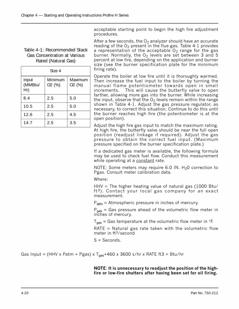
Chapter 4 — Starting and Operating Instructions Profire H Series
acceptable starting point to begin the high fire adjustmentprocedures.
After a few seconds, the O2 analyzer should have an accuratereading of the O2 present in the flue gas. Table 4-1 providesa representation of the acceptable O2 range for the gasburner. Normally, the O2 levels are set between 3 and 5percent at low fire, depending on the application and burnersize (see the burner specification plate for the minimumfiring rate).
Operate the boiler at low fire until it is thoroughly warmed.Then increase the fuel input to the boiler by turning themanual f lame potentiometer towards open in smallincrements. This will cause the butterfly valve to openfarther, allowing more gas into the burner. While increasingthe input, observe that the O2 levels remain within the rangeshown in Table 4-1. Adjust the gas pressure regulator, asnecessary, to correct this situation. Continue to do this untilthe burner reaches high fire (the potentiometer is at theopen position).
Adjust the high fire gas input to match the maximum rating.At high fire, the butterfly valve should be near the full openposition (readjust linkage if required). Adjust the gaspressure to obtain the correct fuel input. (Maximumpressure specified on the burner specification plate.)
If a dedicated gas meter is available, the following formulamay be used to check fuel flow. Conduct this measurementwhile operating at a constant rate.
NOTE: Some meters may require 6.0 IN. H20 correction toPgas. Consult meter calibration data.
Where:
HHV = The higher heating value of natural gas (1000 Btu/ft3) . Contact your local gas company for an exactmeasurement.
Patm = Atmospheric pressure in inches of mercury.
Pgas = Gas pressure ahead of the volumetric flow meter ininches of mercury.
Tgas = Gas temperature at the volumetric flow meter in °F.
RATE = Natural gas rate taken with the volumetric flowmeter in ft3/second
S = Seconds.
Gas Input = (HHV x Patm + Pgas) x Tgas+460 x 3600 s/hr x RATE ft3 = Btu/hr
NOTE: It is unnecessary to readjust the position of the high-fire or low-fire shutters after having been set for oil firing.
Table 4-1: Recommended Stack Gas Concentration at Various
Rated (Natural Gas)
Size 4
Input (MMBtu/Hr)
Minimum O2 (%)
Maximum O2 (%)
8.4 2.5 5.0
10.5 2.5 5.0
12.6 2.5 4.5
14.7 2.5 3.5
4-20 Part No. 750-212
Chapter 4 — Starting and Operating Instructions Profire H Series
Modulate the burner to low fire. The butterfly valve should beadjusted to provide the correct fuel pressure at the low-fireposition in accordance with the burner data plate minimumgas-pressure rating.
FUEL FLOW ADJUSTMENTS. Fuel flow rates are adjusted toprovide the design-rated heat inputs into the burner at bothhigh-fire (maximum rate) and low-fire (minimum rate)operating conditions. The maximum and minimum fuelinput flow rates for the burner are identified on the dataplate. Natural gas flow rates are specified in cfh (cubic feetper hour), and fuel oil flow rates are specified in gph (gallonsper hour).
Fuel flow rate adjustment for both natural gas and oil isaccomplished by regulating the fuel pressure against a fixeddiameter orifice (nozzle). The methods for accomplishingthe pressure regulation, however, are different for naturalgas and oil.
The method for regulating the natural gas f low rate(manifold pressure) is as follows:
Maximum flow rate is established by operating the burner athigh-fire with the butterfly valve fully open, then adjustingthe manifold pressure to the maximum as specified on thedata plate. Maximum manifold pressure is obtained byadjusting the main gas pressure regulator on the gas trainwhile operating the burner at high-fire.
Gas flow modulation for turndown is accomplished bythrottling the flow rate with the butterfly valve. The flowrestriction of the partially closed butterfly valve reduces theflow of gas through the burner nozzle. The butterfly valvethrottling position is controlled by linkage from the main airshutter shaft, which is operated by the modulating motor.
With the modulating motor positioned for low-fire operation,the butterfly valve linkage is adjusted to provide theminimum pressure in the nozzle manifold, as specified onthe burner data plate.
The method for regulating the fuel-oil flow rate (nozzlepressure) is as follows:
Maximum flow rate is established by operating the burner athigh-fire with the oil metering valve in a nearly closedposition with the modulating motor set at the high-fireposition. In this position, the flow of fuel oil through the oilby-pass is minimal, resulting in nearly maximum flowpressure from the pump. High-fire oil flow adjustment isaccomplished by adjusting the linkage to the oil meteringvalve so that the burner nozzle pressure equals themaximum oil pressure specification on the burner dataplate.
Oil pressure modulation for turndown to low-fire operation isaccomplished by increasing the flow rate of oil through the
Part No. 750-212 4-21
Chapter 4 — Starting and Operating Instructions Profire H Series
oil by-pass loop, which reduces pressure in the burnernozzle. This is accomplished by setting the modulatingmotor to the low-fire position, which causes the oil meteringvalve to open. While in this position, the oil metering valvelinkage can be adjusted so that the burner nozzle pressureequals the minimum oil pressure specification on the burnerspecification plate.
G. STARTUP, OPERATING AND SHUTDOWN - ALL FUELS
Depending upon the fuel being burned, the applicableprevious Chapters in Chapter 4 should be reviewed forpreliminary instructions.
The fuel selector switch should be, accordingly, set to eitheroil or gas.
Set the manual-automatic switch to “manual” and turn themanual flame control to “close.”
Turn burner switch to “ON.” The load demand light shouldglow. The low-water level light should remain out, indicatinga safe water level in the boiler. The programmer is nowsequencing. See Chapter 3 for sequence details.
On an initial starting attempt, several efforts might berequired to accomplish “bleeding” of fuel lines, main orpilot. If ignition does not then occur, do not repeatunsuccessful attempts without rechecking the burner andpilot adjustment.
On ignition failure, the flame failure light will glow and theblower will purge the boiler of unburned fuel vapors beforestopping. After ignition failure, wait a few moments beforere-setting the lockout switch.
After main flame ignition, the burner should be set onmanual control at its low fire setting (that is, with manualflame control at “close”) until the boiler is properly warmed.In the case of a steam boiler, CLOSE THE VENT VALVE whenthe steam begins to appear.
A hot water boiler must have a continuous flow of systemwater through the vessel during the warm-up period. Theentire water content of the system and boiler must bewarmed prior to increasing fuel input.
If the flame at low fire provides insufficient heat to reachnormal operating pressure or temperature after 30 minutes,gradually increase the firing rate by turning the manualflame control in one point increments. Operate at theincreased fuel input rate for a period of time until anincrease is noted in pressure or temperature.
After the boiler is thoroughly warmed, turn the manual flamecontrol to high fire. At this point a combustion analysisshould be made, with instruments, and fuel flow regulated asrequired. After making the high-fire adjustment, manually
! Warning
Do not re-light the pilot orattempt to star t the mainburner, either oil or gas, if thecombustion chamber is hotand/or if gas or oil vaporcombust ion gases a represent in the furnace or fluepassages. Failure to followthese instruct ions couldresult in serious personalinjury or death.
! Warning
The burner and cont ro lsystem is designed to providea “pre-purge” period of fanopera t ion pr io r toestablishing ignition sparkand p i lo t f l ame. Do notattempt to alter the system ortake any action that mightcircumvent the “pre-purge”feature. Fai lure to fol lowthese instruct ions couldresult in serious personalinjury or death.
4-22 Part No. 750-212
Chapter 4 — Starting and Operating Instructions Profire H Series
decrease the firing rate to analyze combustion gases, andadjust as required.
To properly perform the testing and adjusting, it isnecessary that the burner be allowed to fire at a maximumrate long enough to achieve desired results.
Operating - Normal operation of the burner should be withthe switch in the automatic position and under the directionof the modulating control. The manual position is providedfor initial adjustment of the burner over the entire firingrange. When a shutdown occurs while operating in themanual position at other than low fire, the damper will notbe in a closed position, thus allowing more air than desiredto flow through the boiler. The hot flame to cool air cyclingsubjects the pressure vessel metal and refractory toundesirables conditions.
With the switch set at “auto,” the burner will operate on amodulating basis according to the load demand.
The burner will continue to operate with modulated firinguntil the operating limit pressure or temperature is reached,unless:
The burner is manually turned “off.”
A low-water condition is detected by low-water level control.
The electrical or fuel supply is interrupted.
The combustion air pressure drops below minimum level.
There can be other reasons for shutdown such as motoroverload, flame outages, tripped circuit breakers, blownfuses, or through other interlock devices in the circuitry.
When the burner is shut down normally, by either theoperating limit control or by manually switching the burneroff, the load demand light no longer glows.
Shutdown through conditions causing safety or interlockcontrols to open will actuate the flame failure light (andalarm if so equipped) and the load demand light will remainlit. The cause of this type of shutdown will have to be located,investigated, and corrected before operation can beresumed. Refer to the troubleshooting section in Chapter 5.
Shutdown - When the operating limit control setting isreached to open the circuit or if the burner switch is turned“off,” the following sequence occurs.
The fuel valve is deenergized and the flame is extinguished.The timer begins operation and the blower motor continuesrunning to force air through the furnace in the post-purgeperiod.
At the end of the programmed post-purge period, the blowermotor is turned off. The timer has returned to its originalstarting position and stops. The unit is ready to re-start.
! Warning
It is advisable to check fortight shut-off of fuel valves.Despite precaut ions andstrainers, foreign material ineither new or renovated fuellines may lodge under a valveseat and prevent t i gh tclosure. The situation isespec ia l l y t rue in newins ta l l a t ions . Prompt lycor rec t any cond i t ionscausing leakage. Failure tofol low these instructionscou ld resu l t in se r iouspersonal injury or death.
Part No. 750-212 4-23
Chapter 4 — Starting and Operating Instructions Profire H Series
H.CONTROL OPERATIONAL TEST AND CHECKS
Proper operation of the various controls should be verifiedand tested when the boiler is initially placed into service, orwhenever a control is replaced. Periodic checks should bemade thereafter in accordance with a planned maintenanceprogram.
The operating limit control may be checked by allowingsteam pressure to increase until the burner shuts down.Depending upon the load, it may be necessary to manuallyincrease the firing rate to raise steam pressure to the burnershut off point. If the load is heavy, the header valve can beclosed or throttled until the pressure increases. Observe thesteam gauge to check the cut off pressure as the operatinglimit control shuts the burner down. Slowly open the headervalve to release steam pressure and check the cut-in settingas the burner restarts. Check the modulating control for thedesired operating pressure range.
The water temperature on a hot water boiler that may beoperating at less than full load may be raised by manuallyincreasing the firing rate until the burner shuts downthrough the action of the operating limit control. Observe thethermometer to verify the desired settings at the point ofcut-out and again when the burner restarts. Return themanual automatic switch to “automatic” and check themodulating control for the desired temperature range.
Check the proper operation and setting of the low-watercutoff and the auxiliary low water cutoff (and pumpoperating control, if used).
Proper operation of the flame failure device should bechecked at startup and at least once a week thereafter.Check the program relay’s annunciation for any systemfailure. Observe the promptness of ignition of the pilot flameand the main flame.
4-24 Part No. 750-212
Milwaukee, Wisconsin
www.cleaver-brooks.com
Chapter 5
Profire D Series Burner
Table of Contents
DESCRIPTION . . . . . . . . . . . . . . . . . . . . . . . . . . . . . . . . . . . . . 5-2OPERATING CONTROLS / CONTROL PANEL . . . . . . . . . . . . . . . . 5-2FLAME SAFETY CONTROLS (see Figure 5-3) . . . . . . . . . . . . . . . 5-3COMBUSTION AIR HANDLING SYSTEM . . . . . . . . . . . . . . . . . . 5-3FIRING RATE CONTROLS . . . . . . . . . . . . . . . . . . . . . . . . . . . . . 5-6FIRING HEAD . . . . . . . . . . . . . . . . . . . . . . . . . . . . . . . . . . . . . 5-6OIL SYSTEM AIR ATOMIZING . . . . . . . . . . . . . . . . . . . . . . . . . . 5-6GAS SYSTEM . . . . . . . . . . . . . . . . . . . . . . . . . . . . . . . . . . . . . . 5-12OPERATION . . . . . . . . . . . . . . . . . . . . . . . . . . . . . . . . . . . . . . 5-14GAS SYSTEM . . . . . . . . . . . . . . . . . . . . . . . . . . . . . . . . . . . . . . 5-16OIL SYSTEM . . . . . . . . . . . . . . . . . . . . . . . . . . . . . . . . . . . . . . 5-18MANUAL SHUTDOWN . . . . . . . . . . . . . . . . . . . . . . . . . . . . . . . 5-20SAFETY SHUTDOWN . . . . . . . . . . . . . . . . . . . . . . . . . . . . . . . . 5-20
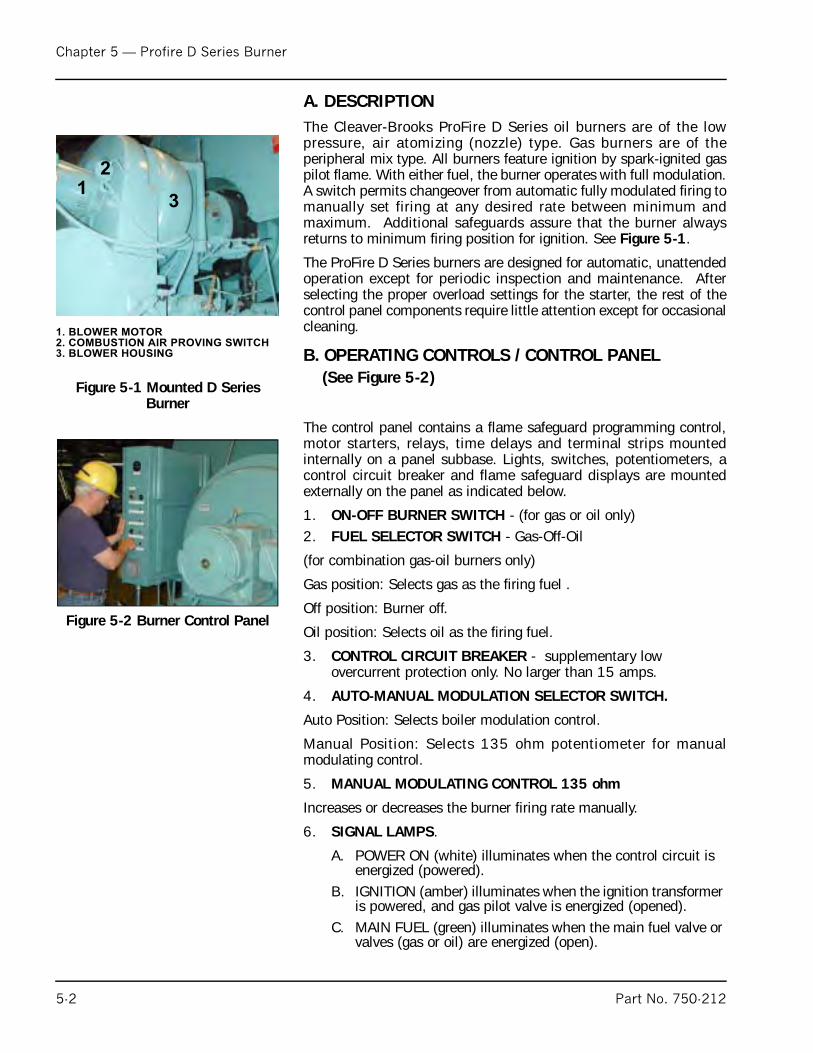
Chapter 5 — Profire D Series Burner
A. DESCRIPTIONThe Cleaver-Brooks ProFire D Series oil burners are of the lowpressure, air atomizing (nozzle) type. Gas burners are of theperipheral mix type. All burners feature ignition by spark-ignited gaspilot flame. With either fuel, the burner operates with full modulation.A switch permits changeover from automatic fully modulated firing tomanually set firing at any desired rate between minimum andmaximum. Additional safeguards assure that the burner alwaysreturns to minimum firing position for ignition. See Figure 5-1.
The ProFire D Series burners are designed for automatic, unattendedoperation except for periodic inspection and maintenance. Afterselecting the proper overload settings for the starter, the rest of thecontrol panel components require little attention except for occasionalcleaning.
B. OPERATING CONTROLS / CONTROL PANEL (See Figure 5-2)
The control panel contains a flame safeguard programming control,motor starters, relays, time delays and terminal strips mountedinternally on a panel subbase. Lights, switches, potentiometers, acontrol circuit breaker and flame safeguard displays are mountedexternally on the panel as indicated below.
1. ON-OFF BURNER SWITCH - (for gas or oil only)2. FUEL SELECTOR SWITCH - Gas-Off-Oil
(for combination gas-oil burners only)
Gas position: Selects gas as the firing fuel .
Off position: Burner off.
Oil position: Selects oil as the firing fuel.
3. CONTROL CIRCUIT BREAKER - supplementary low overcurrent protection only. No larger than 15 amps.
4. AUTO-MANUAL MODULATION SELECTOR SWITCH.
Auto Position: Selects boiler modulation control.
Manual Position: Selects 135 ohm potentiometer for manualmodulating control.
5. MANUAL MODULATING CONTROL 135 ohm
Increases or decreases the burner firing rate manually.
6. SIGNAL LAMPS.
A. POWER ON (white) illuminates when the control circuit is energized (powered).
B. IGNITION (amber) illuminates when the ignition transformer is powered, and gas pilot valve is energized (opened).
C. MAIN FUEL (green) illuminates when the main fuel valve or valves (gas or oil) are energized (open).
Figure 5-1 Mounted D Series Burner
1. BLOWER MOTOR
2. COMBUSTION AIR PROVING SWITCH
3. BLOWER HOUSING
1
2
3
Figure 5-2 Burner Control Panel
5-2 Part No. 750-212
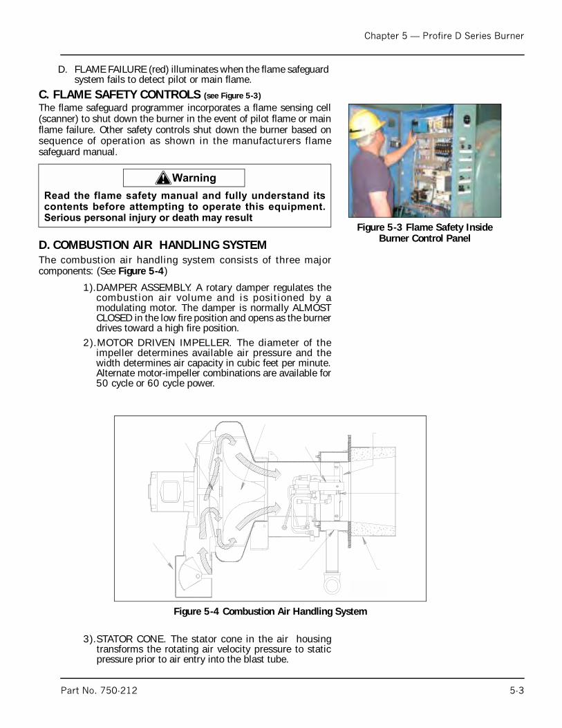
Chapter 5 — Profire D Series Burner
D. FLAME FAILURE (red) illuminates when the flame safeguard system fails to detect pilot or main flame.
C. FLAME SAFETY CONTROLS (see Figure 5-3)
The flame safeguard programmer incorporates a flame sensing cell(scanner) to shut down the burner in the event of pilot flame or mainflame failure. Other safety controls shut down the burner based onsequence of operation as shown in the manufacturers flamesafeguard manual.
D. COMBUSTION AIR HANDLING SYSTEMThe combustion air handling system consists of three majorcomponents: (See Figure 5-4)
1).DAMPER ASSEMBLY. A rotary damper regulates thecombustion air volume and is positioned by amodulating motor. The damper is normally ALMOSTCLOSED in the low fire position and opens as the burnerdrives toward a high fire position.
2).MOTOR DRIVEN IMPELLER. The diameter of theimpeller determines available air pressure and thewidth determines air capacity in cubic feet per minute.Alternate motor-impeller combinations are available for50 cycle or 60 cycle power.
3).STATOR CONE. The stator cone in the air housingtransforms the rotating air velocity pressure to staticpressure prior to air entry into the blast tube.
Figure 5-3 Flame Safety Inside Burner Control Panel
! Warning
Read the flame safety manual and fully understand itscontents before attempting to operate this equipment.Serious personal injury or death may result
Figure 5-4 Combustion Air Handling System
Part No. 750-212 5-3
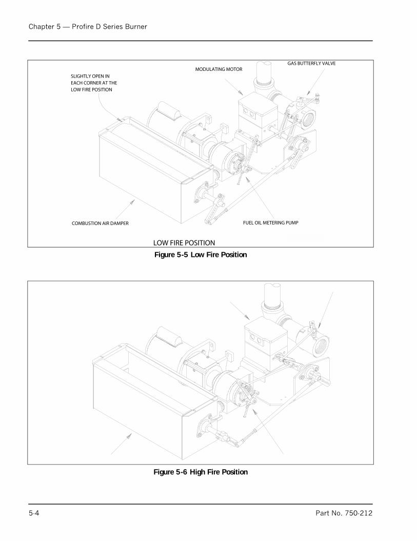
Chapter 5 — Profire D Series Burner
Figure 5-5 Low Fire Position
Figure 5-6 High Fire Position
5-4 Part No. 750-212

Chapter 5 — Profire D Series Burner
Figure 5-7 Cam Trim Adjustment
Figure 5-8 Firing Head Assembly
Part No. 750-212 5-5
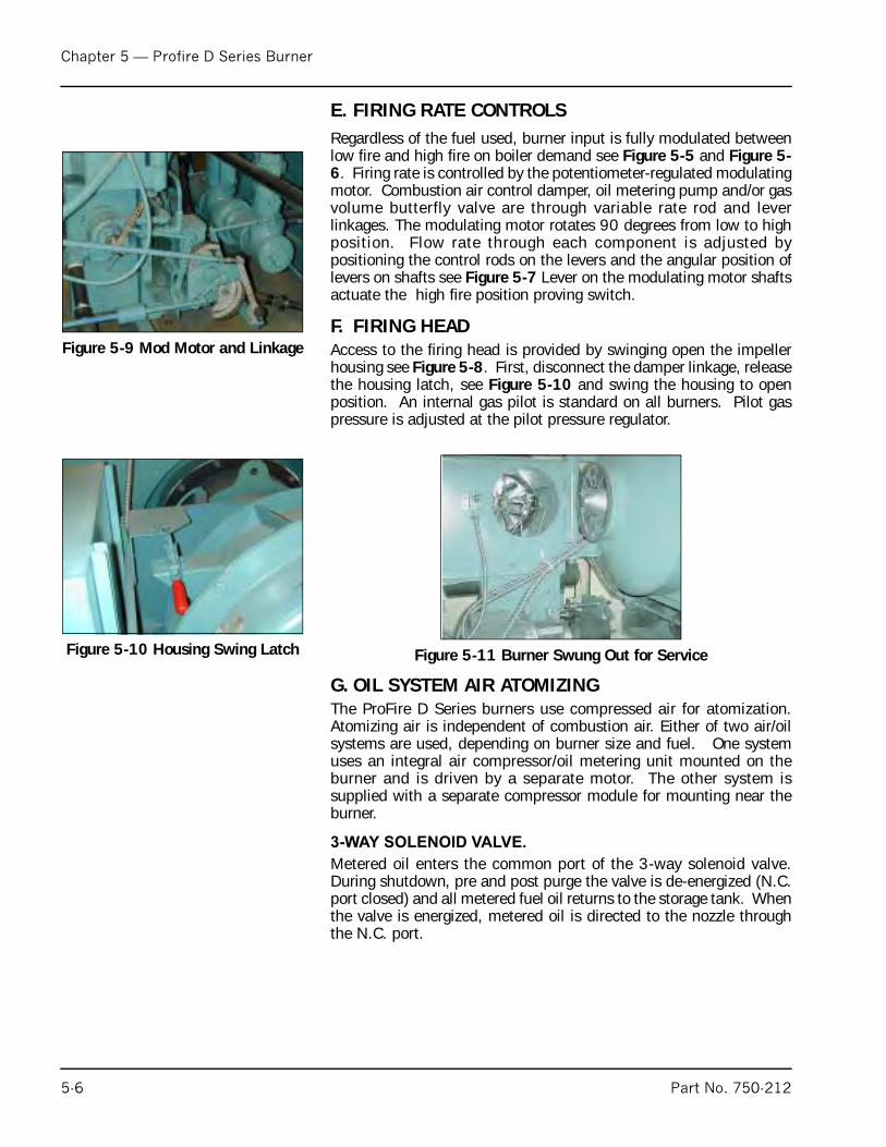
Chapter 5 — Profire D Series Burner
E. FIRING RATE CONTROLS
Regardless of the fuel used, burner input is fully modulated betweenlow fire and high fire on boiler demand see Figure 5-5 and Figure 5-6. Firing rate is controlled by the potentiometer-regulated modulatingmotor. Combustion air control damper, oil metering pump and/or gasvolume butterfly valve are through variable rate rod and leverlinkages. The modulating motor rotates 90 degrees from low to highposition. Flow rate through each component is adjusted bypositioning the control rods on the levers and the angular position oflevers on shafts see Figure 5-7 Lever on the modulating motor shaftsactuate the high fire position proving switch.
F. FIRING HEADAccess to the firing head is provided by swinging open the impellerhousing see Figure 5-8. First, disconnect the damper linkage, releasethe housing latch, see Figure 5-10 and swing the housing to openposition. An internal gas pilot is standard on all burners. Pilot gaspressure is adjusted at the pilot pressure regulator.
G. OIL SYSTEM AIR ATOMIZINGThe ProFire D Series burners use compressed air for atomization.Atomizing air is independent of combustion air. Either of two air/oilsystems are used, depending on burner size and fuel. One systemuses an integral air compressor/oil metering unit mounted on theburner and is driven by a separate motor. The other system issupplied with a separate compressor module for mounting near theburner.
3-WAY SOLENOID VALVE.
Metered oil enters the common port of the 3-way solenoid valve.During shutdown, pre and post purge the valve is de-energized (N.C.port closed) and all metered fuel oil returns to the storage tank. Whenthe valve is energized, metered oil is directed to the nozzle throughthe N.C. port.
Figure 5-9 Mod Motor and Linkage
Figure 5-10 Housing Swing Latch Figure 5-11 Burner Swung Out for Service
5-6 Part No. 750-212
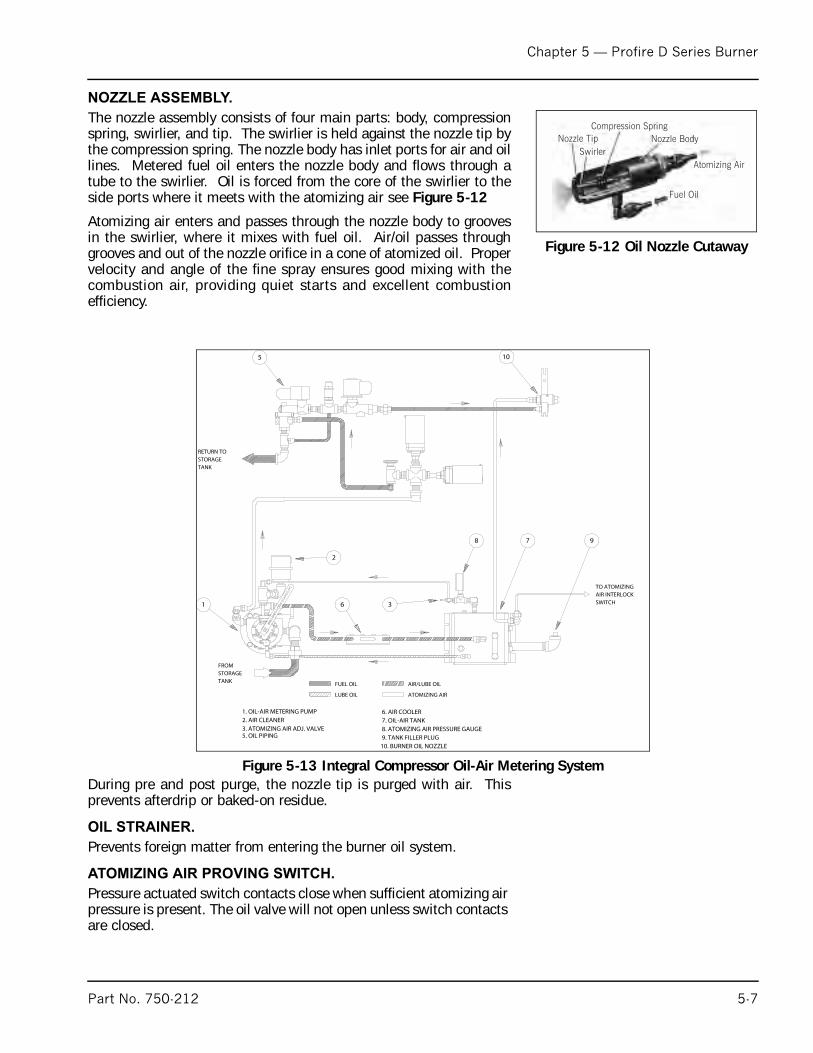
Chapter 5 — Profire D Series Burner
NOZZLE ASSEMBLY.
The nozzle assembly consists of four main parts: body, compressionspring, swirlier, and tip. The swirlier is held against the nozzle tip bythe compression spring. The nozzle body has inlet ports for air and oillines. Metered fuel oil enters the nozzle body and flows through atube to the swirlier. Oil is forced from the core of the swirlier to theside ports where it meets with the atomizing air see Figure 5-12
Atomizing air enters and passes through the nozzle body to groovesin the swirlier, where it mixes with fuel oil. Air/oil passes throughgrooves and out of the nozzle orifice in a cone of atomized oil. Propervelocity and angle of the fine spray ensures good mixing with thecombustion air, providing quiet starts and excellent combustionefficiency.
During pre and post purge, the nozzle tip is purged with air. Thisprevents afterdrip or baked-on residue.
OIL STRAINER.
Prevents foreign matter from entering the burner oil system.
ATOMIZING AIR PROVING SWITCH.
Pressure actuated switch contacts close when sufficient atomizing air pressure is present. The oil valve will not open unless switch contacts are closed.
Figure 5-12 Oil Nozzle Cutaway
SwirlerNozzle Tip
Compression SpringNozzle Body
Fuel Oil
Atomizing Air
Figure 5-13 Integral Compressor Oil-Air Metering System
Part No. 750-212 5-7

Chapter 5 — Profire D Series Burner
AIR/LUBE OIL TANK.
Burner mounted tank stores compressed air for oil atomization andoil for compressor lubrication. Contains wire mesh filter to separatelube oil from compressed air.
INTEGRAL AIR/OIL UNIT.
Model designation DL, DLG, DM, DMG No. 2 oil with air atomization(model D42 to 145). These models utilize an integral air compressor/oil metering unit which is separately driven at 1725 rpm andmounted on the burner. See Figure 5-13
AIR COMPRESSOR.
Air is drawn into the vane-type, rotary compressor section of the air/oil unit through an air cleaner (see Figure 5-14). The compressed airflows to an air-lube oil tank which serves the multiple purpose of lubeoil mist recovery, lube oil sump and air storage. The compressor iscooled and lubricated continuously by oil under pressure from thebottom of the tank. Oil vapor is extracted from the compressor air,by a mist eliminator in the upper section of the tank. Atomizing airflows to the nozzle at a constant volume, but air pressure increasesas the firing rate increases. Atomizing air is regulated by an adjustingvalve in the return air line on integral metering units or in the air inleton air compressor module burners.
SEPARATE COMPRESSOR MODULE.
All models DE, DEG, (also DL, DMG, DM, DMG 175-420) burnershave, a burner mounted oil metering unit and a separate compressormodule. The system functions as follows
AIR COMPRESSOR MODULE.
Air is supplied by a positive displacement rotary vane compressor.This provides a constant volume of atomizing air regardless ofpressure. The compressor module includes motor, air-oil reservoirtank, air filter and lube oil cooling coil. Air enters the compressorthrough the filter. The air flows from the compressor into the air-oilseparating and reservoir tank. Filtering material and baffles separate
Figure 5-14 Air Compressor Cutaway
Inlet Channel
Mechanical Seal
Air InletCompressed Air Discharge
Rotary Vane
Air Compressor
Fuel Oil Inlet
Discharge Channel
Rotor
PistonSleeve
Eccentric Plate
Eccentric Shaft and Pin
5-8 Part No. 750-212
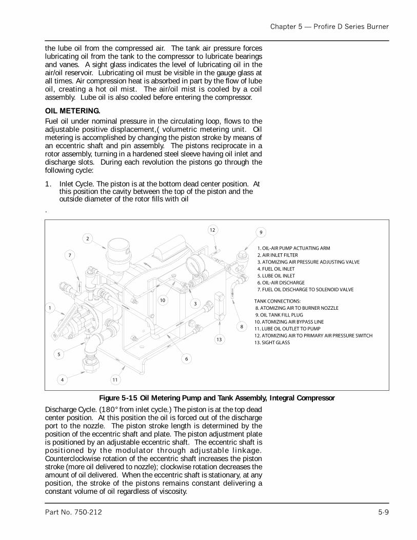
Chapter 5 — Profire D Series Burner
the lube oil from the compressed air. The tank air pressure forceslubricating oil from the tank to the compressor to lubricate bearingsand vanes. A sight glass indicates the level of lubricating oil in theair/oil reservoir. Lubricating oil must be visible in the gauge glass atall times. Air compression heat is absorbed in part by the flow of lubeoil, creating a hot oil mist. The air/oil mist is cooled by a coilassembly. Lube oil is also cooled before entering the compressor.
OIL METERING.
Fuel oil under nominal pressure in the circulating loop, flows to theadjustable positive displacement,( volumetric metering unit. Oilmetering is accomplished by changing the piston stroke by means ofan eccentric shaft and pin assembly. The pistons reciprocate in arotor assembly, turning in a hardened steel sleeve having oil inlet anddischarge slots. During each revolution the pistons go through thefollowing cycle:
1. Inlet Cycle. The piston is at the bottom dead center position. At this position the cavity between the top of the piston and the outside diameter of the rotor fills with oil
.
Discharge Cycle. (180° from inlet cycle.) The piston is at the top deadcenter position. At this position the oil is forced out of the dischargeport to the nozzle. The piston stroke length is determined by theposition of the eccentric shaft and plate. The piston adjustment plateis positioned by an adjustable eccentric shaft. The eccentric shaft isposit ioned by the modulator through adjustable l inkage.Counterclockwise rotation of the eccentric shaft increases the pistonstroke (more oil delivered to nozzle); clockwise rotation decreases theamount of oil delivered. When the eccentric shaft is stationary, at anyposition, the stroke of the pistons remains constant delivering aconstant volume of oil regardless of viscosity.
Figure 5-15 Oil Metering Pump and Tank Assembly, Integral Compressor
Part No. 750-212 5-9
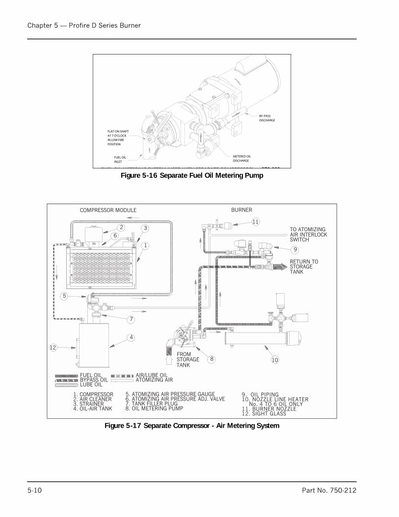
Chapter 5 — Profire D Series Burner
Figure 5-16 Separate Fuel Oil Metering Pump
Figure 5-17 Separate Compressor - Air Metering System
12
LUBE OIL
9. OIL PIPING10. NOZZLE LINE HEATER
No. 4 TO 6 OIL ONLY11. BURNER NOZZLE12. SIGHT GLASS
FROMSTORAGETANK
TO ATOMIZINGAIR INTERLOCKSWITCH
RETURN TOSTORAGETANK
COMPRESSOR MODULE BURNER
1. COMPRESSOR2. AIR CLEANER3. STRAINER4. OIL-AIR TANK
5. ATOMIZING AIR PRESSURE GAUGE6. ATOMIZING AIR PRESSURE ADJ. VALVE7. TANK FILLER PLUG8. OIL METERING PUMP
FUEL OILBYPASS OIL ATOMIZING AIR
AIR/LUBE OIL
2
6
1
3
5
7
4
8 10
11
9
5-10 Part No. 750-212
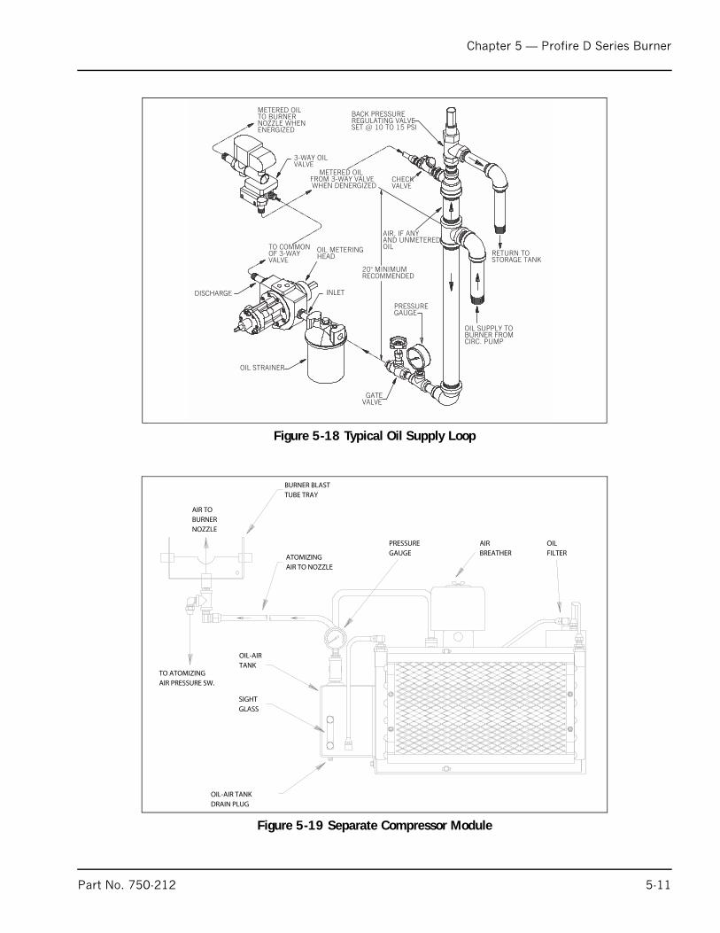
Chapter 5 — Profire D Series Burner
Figure 5-18 Typical Oil Supply Loop
AIR, IF ANYAND UNMETEREDOIL
20" MINIMUMRECOMMENDED
OIL METERINGHEAD
OIL STRAINER
GATEVALVE
METERED OILFROM 3-WAY VALVEWHEN DENERGIZED
METERED OILTO BURNERNOZZLE WHENENERGIZED
TO COMMONOF 3-WAYVALVE
INLETDISCHARGE
3-WAY OILVALVE
PRESSUREGAUGE
CHECKVALVE
BACK PRESSUREREGULATING VALVESET @ 10 TO 15 PSI
RETURN TOSTORAGE TANK
OIL SUPPLY TOBURNER FROMCIRC. PUMP
Figure 5-19 Separate Compressor Module
Part No. 750-212 5-11
Chapter 5 — Profire D Series Burner
OPERATION
Fuel is delivered to the positive displacement metering pump at 10to 15 psi. Metered oil is delivered to the common port of a 3-waysolenoid valve for transfer to the burner nozzle through the normallyclosed port or back to the storage tank through the normally openport. During pre - and post purge, metered oil is returned to the tank.During normal firing, all metered oil is delivered to the nozzle. Heavyoil burners have a supplementary nozzle line heater between themetering pump and the 3-way valve. For the description of typicalfuel oil piping installations, see Figure 5-18. Air enters a rotary vanecompressor through an air cleaner where it is compressed toatomizing pressure. Air flows from the compressor to an air oil tankwhich serves the multiple purpose of dampening air pulsation, lubeoil mist recovery, lube oil and atomizing air storage. The compressorrotor is cooled and lubricated continuously by oil under pressure fromthe air oil tank. Oil vapor is extracted by a mist eliminator in theupper section of the tank. Atomizing air from the upper tank sectionis delivered to the nozzle at a constant volume. Air pressure increasesas the burner firing rate increases. Atomizing pressure may beadjusted by the needle valve located on the air-oil pump. The valveallows air to be bled from the tank to the compressor inlet. Deliveryrate of the fuel oil metering pump is controlled by the modulatingmotor through adjustable linkage.
H. GAS SYSTEMGas is introduced into the combustion zone from a circular manifoldthrough multiple ports in the blast tube. Firing rate is determined bythe size and number of ports, by manifold pressure and bycombustion zone pressure. The firing rate is regulated by a rotary,butterfly type throttling valve at the manifold inlet. The valve isactuated by an adjustable linkage from the modulating motor.Depending upon specific requirements, one or two safety shutoff,motorized main gas valves are provided for installation in the gas trainupstream of the butterfly valve. Safety shutoff gas valves are wiredinto the programming control to automatically open and close at theproper time in the operating sequence.
MAIN GAS TRAIN COMPONENTS
Depending upon the requirements of the regulating authority, the gascontrol system and gas train may consist of some, or all, of thefollowing items. A typical gas train is shown in Figure 5-20.
GAS VOLUME VALVE.
The butterfly type valve is positioned by linkage from the modulatingmotor and controls the rate of flow of gas.
MAIN GAS VALVES.
Electrically operated safety shutoff valve(s) that open to admit gas tothe burner. Standard UL. burners include:
-Models: D42; One motorized gas valve and one solenoid valve
-Models: D54-105; One motorized gas valve with closure interlockand one solenoid valve.
5-12 Part No. 750-212
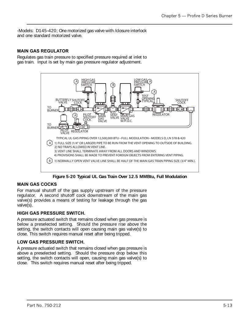
Chapter 5 — Profire D Series Burner
-Models: D145-420; One motorized gas valve with /closure interlockand one standard motorized valve.
MAIN GAS REGULATOR
Regulates gas train pressure to specified pressure required at inlet togas train. Input is set by main gas pressure regulator adjustment.
MAIN GAS COCKS
For manual shutoff of the gas supply upstream of the pressureregulator. A second shutoff cock downstream of the main gasvalve(s) provides a means of testing for leakage through the gasvalve(s).
HIGH GAS PRESSURE SWITCH.
A pressure actuated switch that remains closed when gas pressure isbelow a preselected setting. Should the pressure rise above thesetting, the switch contacts will open causing main gas valve(s) toclose. This switch requires manual reset after being tripped.
LOW GAS PRESSURE SWITCH.
A pressure actuated switch that remains closed when gas pressure isabove a preselected setting. Should the pressure drop below thissetting, the switch contacts will open, causing main gas valve(s) toclose. This switch requires manual reset after being tripped.
Figure 5-20 Typical UL Gas Train Over 12.5 MMBtu, Full Modulation
B 1) NORMALLY OPEN VENT VALVE LINE SHALL BE HALF OF THE MAIN GAS TRAIN PIPING SIZE (3/4" MIN.).
B
A
PILOTVALVE
A
AA
SHUTOFFCOCK
REGULATOR
TESTOPENINGTYPICAL
LOW GASPRESSURESWITCH
HIGH GASPRESSURESWITCH
SHUTOFFCOCK
PILOTSHUTOFFCOCK
REGULATOR
BUTTERFLYVALVE
TOBURNER
TOBURNER
MAIN GASVALVEW/P.O.C.
N.O.VENTVALVEMAIN
GASVALVE
A 1) FULL SIZE (1/4" OR LARGER) PIPE TO BE RUN FROM THE VENT OPENING TO OUTSIDE OF BUILDING.2) NO TRAPS ALLOWED IN VENT LINE.3) VENT LINE SHALL TERMINATE AWAY FROM ALL DOORS AND WINDOWS.4) PROVISIONS SHALL BE MADE TO PREVENT FOREIGN OBJECTS FROM ENTERING VENT PIPING.
TYPICAL UL GAS PIPING OVER 12,500,000 BTU - FULL MODULATION - MODELS D, LN 378 & 420
Part No. 750-212 5-13
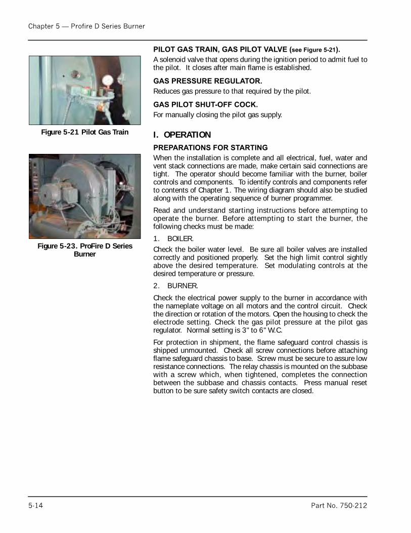
Chapter 5 — Profire D Series Burner
PILOT GAS TRAIN, GAS PILOT VALVE (see Figure 5-21).
A solenoid valve that opens during the ignition period to admit fuel tothe pilot. It closes after main flame is established.
GAS PRESSURE REGULATOR.
Reduces gas pressure to that required by the pilot.
GAS PILOT SHUT-OFF COCK.
For manually closing the pilot gas supply.
I. OPERATION PREPARATIONS FOR STARTING
When the installation is complete and all electrical, fuel, water andvent stack connections are made, make certain said connections aretight. The operator should become familiar with the burner, boilercontrols and components. To identify controls and components referto contents of Chapter 1. The wiring diagram should also be studiedalong with the operating sequence of burner programmer.
Read and understand starting instructions before attempting tooperate the burner. Before attempting to start the burner, thefollowing checks must be made:
1. BOILER. Check the boiler water level. Be sure all boiler valves are installedcorrectly and positioned properly. Set the high limit control sightlyabove the desired temperature. Set modulating controls at thedesired temperature or pressure.
2. BURNER.
Check the electrical power supply to the burner in accordance withthe nameplate voltage on all motors and the control circuit. Checkthe direction or rotation of the motors. Open the housing to check theelectrode setting. Check the gas pilot pressure at the pilot gasregulator. Normal setting is 3" to 6" W.C.
For protection in shipment, the flame safeguard control chassis isshipped unmounted. Check all screw connections before attachingflame safeguard chassis to base. Screw must be secure to assure lowresistance connections. The relay chassis is mounted on the subbasewith a screw which, when tightened, completes the connectionbetween the subbase and chassis contacts. Press manual resetbutton to be sure safety switch contacts are closed.
Figure 5-21 Pilot Gas Train
Figure 5-23. ProFire D Series Burner
5-14 Part No. 750-212
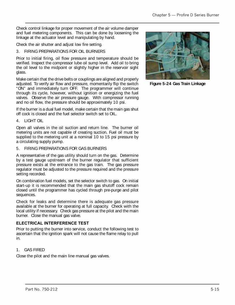
Chapter 5 — Profire D Series Burner
Check control linkage for proper movement of the air volume damperand fuel metering components. This can be done by loosening thelinkage at the actuator level and manipulating by hand.
Check the air shutter and adjust low fire setting.
3. FIRING PREPARATIONS FOR OIL BURNERS
Prior to initial firing, oil flow pressure and temperature should beverified. Inspect the compressor lube oil sump level. Add oil to bringthe oil level to the midpoint or slightly higher in the reservoir sightglass.
Make certain that the drive belts or couplings are aligned and properlyadjusted. To verify air flow and pressure, momentarily flip the switch“ON” and immediately turn OFF. The programmer will continuethrough its cycle, however, without ignition or energizing the fuelvalves. Observe the air pressure gauge. With compressor runningand no oil flow, the pressure should be approximately 10 psi.
If the burner is a dual fuel model, make certain that the main gas shutoff cock is closed and the fuel selector switch set to OIL.
4. LIGHT OIL
Open all valves in the oil suction and return line. The burner oilmetering units are not capable of creating suction. Fuel oil must besupplied to the metering unit at a nominal 10 to 15 psi pressure bya circulating supply pump.
5. FIRING PREPARATIONS FOR GAS BURNERS
A representative of the gas utility should turn on the gas. Determineby a test gauge upstream of the burner regulator that sufficientpressure exists at the entrance to the gas train. The gas pressureregulator must be adjusted to the pressure required and the pressuresetting recorded.
On combination fuel models, set the selector switch to gas. On initialstart-up it is recommended that the main gas shutoff cock remainclosed until the programmer has cycled through pre-purge and pilotsequences.
Check for leaks and determine there is adequate gas pressureavailable at the burner for operating at full capacity. Check with thelocal utility if necessary. Check gas pressure at the pilot and the mainburner. Close the manual gas valve.
ELECTRICAL INTERFERENCE TEST
Prior to putting the burner into service, conduct the following test toascertain that the ignition spark will not cause the flame relay to pullin.
1. GAS FIREDClose the pilot and the main line manual gas valves.
Figure 5-24 Gas Train Linkage
Part No. 750-212 5-15
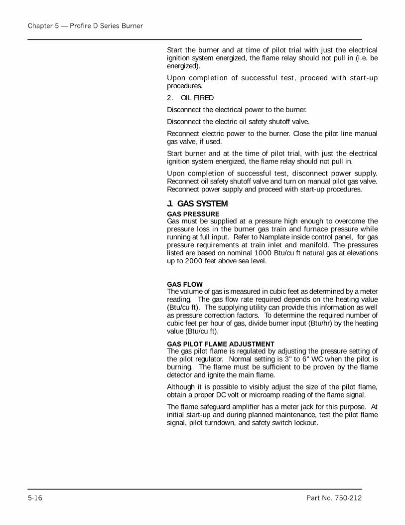
Chapter 5 — Profire D Series Burner
5-1
Start the burner and at time of pilot trial with just the electricalignition system energized, the flame relay should not pull in (i.e. beenergized).
Upon completion of successful test, proceed with start-upprocedures.
2. OIL FIRED
Disconnect the electrical power to the burner.
Disconnect the electric oil safety shutoff valve.
Reconnect electric power to the burner. Close the pilot line manualgas valve, if used.
Start burner and at the time of pilot trial, with just the electricalignition system energized, the flame relay should not pull in.
Upon completion of successful test, disconnect power supply.Reconnect oil safety shutoff valve and turn on manual pilot gas valve.Reconnect power supply and proceed with start-up procedures.
J. GAS SYSTEMGAS PRESSURE
Gas must be supplied at a pressure high enough to overcome thepressure loss in the burner gas train and furnace pressure whilerunning at full input. Refer to Namplate inside control panel, for gaspressure requirements at train inlet and manifold. The pressureslisted are based on nominal 1000 Btu/cu ft natural gas at elevationsup to 2000 feet above sea level.
GAS FLOW
The volume of gas is measured in cubic feet as determined by a meterreading. The gas flow rate required depends on the heating value(Btu/cu ft). The supplying utility can provide this information as wellas pressure correction factors. To determine the required number ofcubic feet per hour of gas, divide burner input (Btu/hr) by the heatingvalue (Btu/cu ft).
GAS PILOT FLAME ADJUSTMENT
The gas pilot flame is regulated by adjusting the pressure setting ofthe pilot regulator. Normal setting is 3" to 6" WC when the pilot isburning. The flame must be sufficient to be proven by the flamedetector and ignite the main flame.
Although it is possible to visibly adjust the size of the pilot flame,obtain a proper DC volt or microamp reading of the flame signal.
The flame safeguard amplifier has a meter jack for this purpose. Atinitial start-up and during planned maintenance, test the pilot flamesignal, pilot turndown, and safety switch lockout.
6 Part No. 750-212
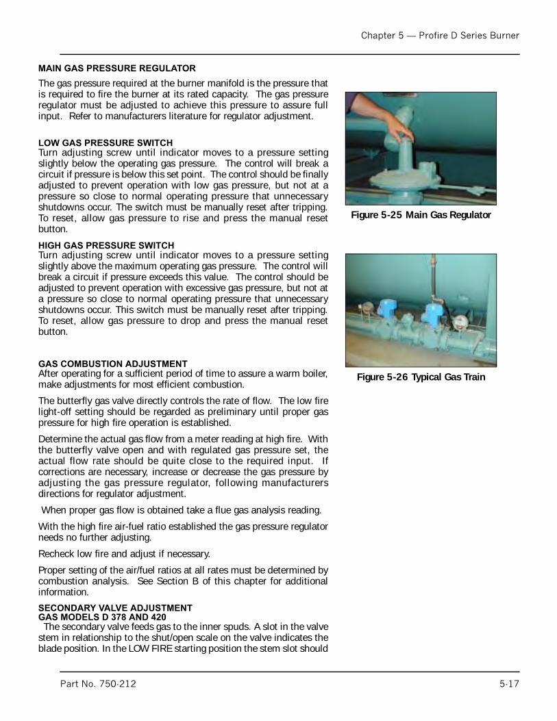
Chapter 5 — Profire D Series Burner
MAIN GAS PRESSURE REGULATOR
The gas pressure required at the burner manifold is the pressure thatis required to fire the burner at its rated capacity. The gas pressureregulator must be adjusted to achieve this pressure to assure fullinput. Refer to manufacturers literature for regulator adjustment.
LOW GAS PRESSURE SWITCH Turn adjusting screw until indicator moves to a pressure settingslightly below the operating gas pressure. The control will break acircuit if pressure is below this set point. The control should be finallyadjusted to prevent operation with low gas pressure, but not at apressure so close to normal operating pressure that unnecessaryshutdowns occur. The switch must be manually reset after tripping.To reset, allow gas pressure to rise and press the manual resetbutton.
HIGH GAS PRESSURE SWITCH
Turn adjusting screw until indicator moves to a pressure settingslightly above the maximum operating gas pressure. The control willbreak a circuit if pressure exceeds this value. The control should beadjusted to prevent operation with excessive gas pressure, but not ata pressure so close to normal operating pressure that unnecessaryshutdowns occur. This switch must be manually reset after tripping.To reset, allow gas pressure to drop and press the manual resetbutton.
GAS COMBUSTION ADJUSTMENT
After operating for a sufficient period of time to assure a warm boiler,make adjustments for most efficient combustion.
The butterfly gas valve directly controls the rate of flow. The low firelight-off setting should be regarded as preliminary until proper gaspressure for high fire operation is established.
Determine the actual gas flow from a meter reading at high fire. Withthe butterfly valve open and with regulated gas pressure set, theactual flow rate should be quite close to the required input. Ifcorrections are necessary, increase or decrease the gas pressure byadjusting the gas pressure regulator, following manufacturersdirections for regulator adjustment.
When proper gas flow is obtained take a flue gas analysis reading.
With the high fire air-fuel ratio established the gas pressure regulatorneeds no further adjusting.
Recheck low fire and adjust if necessary.
Proper setting of the air/fuel ratios at all rates must be determined bycombustion analysis. See Section B of this chapter for additionalinformation.
SECONDARY VALVE ADJUSTMENT
GAS MODELS D 378 AND 420
The secondary valve feeds gas to the inner spuds. A slot in the valvestem in relationship to the shut/open scale on the valve indicates theblade position. In the LOW FIRE starting position the stem slot should
Figure 5-25 Main Gas Regulator
Figure 5-26 Typical Gas Train
Part No. 750-212 5-17
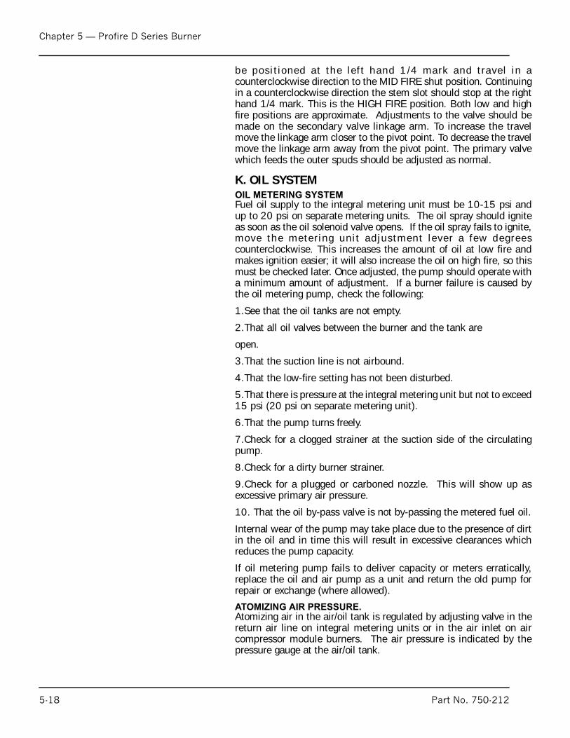
Chapter 5 — Profire D Series Burner
5-1
be posit ioned at the lef t hand 1/4 mark and travel in acounterclockwise direction to the MID FIRE shut position. Continuingin a counterclockwise direction the stem slot should stop at the righthand 1/4 mark. This is the HIGH FIRE position. Both low and highfire positions are approximate. Adjustments to the valve should bemade on the secondary valve linkage arm. To increase the travelmove the linkage arm closer to the pivot point. To decrease the travelmove the linkage arm away from the pivot point. The primary valvewhich feeds the outer spuds should be adjusted as normal.
K. OIL SYSTEMOIL METERING SYSTEM
Fuel oil supply to the integral metering unit must be 10-15 psi andup to 20 psi on separate metering units. The oil spray should igniteas soon as the oil solenoid valve opens. If the oil spray fails to ignite,move the meter ing unit adjustment lever a few degreescounterclockwise. This increases the amount of oil at low fire andmakes ignition easier; it will also increase the oil on high fire, so thismust be checked later. Once adjusted, the pump should operate witha minimum amount of adjustment. If a burner failure is caused bythe oil metering pump, check the following:
1.See that the oil tanks are not empty.
2.That all oil valves between the burner and the tank are
open.
3.That the suction line is not airbound.
4.That the low-fire setting has not been disturbed.
5.That there is pressure at the integral metering unit but not to exceed15 psi (20 psi on separate metering unit).
6.That the pump turns freely.
7.Check for a clogged strainer at the suction side of the circulatingpump.
8.Check for a dirty burner strainer.
9.Check for a plugged or carboned nozzle. This will show up asexcessive primary air pressure.
10. That the oil by-pass valve is not by-passing the metered fuel oil.
Internal wear of the pump may take place due to the presence of dirtin the oil and in time this will result in excessive clearances whichreduces the pump capacity.
If oil metering pump fails to deliver capacity or meters erratically,replace the oil and air pump as a unit and return the old pump forrepair or exchange (where allowed).
ATOMIZING AIR PRESSURE.
Atomizing air in the air/oil tank is regulated by adjusting valve in thereturn air line on integral metering units or in the air inlet on aircompressor module burners. The air pressure is indicated by thepressure gauge at the air/oil tank.
8 Part No. 750-212
Chapter 5 — Profire D Series Burner
A minimum of 10 psi air pressure in low fire is suggested. As thefiring rate increases, the air pressure also increases. Air pressure willbe less with light oils. If any change in atomizing air pressure is made,check ignition several times for reliable light off. Adjustments shouldbe set to obtain reliable ignition with best low and high firecombustion results.
If the required atomizing air pressure cannot be maintained, a lack oflubricating oil may be the cause or the intake filter may be dirty.
ATOMIZING AIR PROVING SWITCH. The knurled nut between the switch and bellows is turned in to raisepressure setting. The minimum amount of atomizing air is duringpre- and post-purge. During pre-purge, adjust switch until it breaksthe circuit. Readjust switch above this circuit break point to actuateunder a condition of minimum pressure, but not so close as to causenuisance shutdowns. Air pressure against the Bourdon tube actuatestwo single pole, single throw mercury switches, which when madecompletes a circuit, proving the presence of atomizing air. Since thepressure of the atomizing air is at minimum when no fuel is presentat the nozzle, adjustment of the switch should be made while the unitis purging, but not firing.
LOW OIL PRESSURE SWITCH
The low oil pressure switch is adjusted at the minimum setting of 4psi. Turning the knob clockwise will increase pressure, counterclockwise will decrease pressure.
HIGH OIL TEMPERATURE SWITCH
The temperature switch is set slightly below the maximum of 260F.To adjust, remove cover and turn the screw located on top. Clockwisewill increase temperature, counter clockwise will decreasetemperature.
NOZZLE LINE HEATER
1. Remove the cover which encloses the thermostat and interlockswitch. The pointer controls the thermostat setting. The knurledknob controls the cold oil interlock switch.
2. The thermostat pointer should be set at position 6 and then raisedor lowered as required. Higher numbers indicate highertemperatures. Let unit run before making further adjustments. Thethermostat governing the nozzle line heater element is set lower thanthe thermostat governing the oil heater in the circulating loop.
3. The cold oil interlock switch is controlled by the small brassknurled knob under the pointer. This is set to prevent the burner fromstarting until proper oil temperature is attained. Set below the oilthermostat setting. If the cold oil interlock is set higher than the oiltemperature, the burner will not run.
4. Replace cover.
START-UP SEQUENCE
The programming control sequences the operation of all controls andcomponents through the starting, ignition, firing, and shutdowncycle. The burner and control system are in starting condition when:
a. The operating and high limit control (temperature or pressure) arebelow their cutoff setting;
Part No. 750-212 5-19
Chapter 5 — Profire D Series Burner
b. All power supply switches are closed;
c. Power is present at the control panel.
Refer to the manufacturers literature on programming controls andburner wiring diagrams for detailed information.
1. Begin starting sequence, with burner switch off, and with all manual valves closed. Switch main power on. (Power On) light.
2. When firing oil, open the manual oil valves.
3. When firing on gas, open the main manual gas valve.
4. When firing on gas, manually reset the high and low gas pressure switches.
5. Place the gas /oil selector switch in position for desired fuel. With all limit and operating controls calling for heat, the burner will follow the Flame Safeguard Sequence below.
6. When the burner motor starts, open the gas cock.
7. If firing on gas, when the main fuel lamp lights indicating pilot flame proven open the manual leak test valve.
AUTOMATIC SHUTDOWN
Limit or operating controls open:
L. MANUAL SHUTDOWN 1. Turn gas/oil selector switch off. Burner shuts down in Automatic
Shutdown as above. 2. When burner motor stops, close all manual valves
M.SAFETY SHUTDOWN If at any time during the operating cycle a flame failure occurs, theburner shuts down as in Automatic Shutdown, with an additionalpost-purge, and the flame failure lamp is energized.
Time in seconds External Operation
0 Provided the fuel valve is proven closed the burner motor and flame safeguard timer will start
7 Air flow must be proven before ignition, or the flame safeguard will lockout. If the interlock circuit opens during a firing period, the burner will shutoff and the flame safeguard will lockout.
60 Firing on gas and providing the air flow and low fire have been proven, the pilot ignition transformer and ignition lamp are energized and the gas pilot valve opens to ignite the pilot.
70 Firing on oil, providing air flow and pilot have been proven, the main fuel lamp lights. When on gas or oil, the main valve opens to ignite the burner at low fire.
80 The pilot ignition transformer is de-energized, and the main safety shut off pilot valve closes, scanner proves main flame only. If the low/auto. switch is in the auto position, the following will occur:
On gas, the butterfly valve and the burner air louvre moves to "low fire" position. On oil, the metering pump and the burner air louvre moves to "low fire" position.
100 "Normal run" position. Burner continues.
100 Fuel valves close. Main fuel lamp goes off. Flame safeguard timer starts
115 Flame safeguard timer and burner motor stop. Burner is ready for start up on the next call for heat
5-20 Part No. 750-212
Milwaukee, Wisconsin
www.cleaver-brooks.com
Chapter 6
Profire D SeriesBurner Maintenance
MAINTENANCE . . . . . . . . . . . . . . . . . . . . . . . . . . . . . . . . . . . . 6-2GENERAL. . . . . . . . . . . . . . . . . . . . . . . . . . . . . . . . . . . . . . . . . 6-2CONTROL SYSTEM . . . . . . . . . . . . . . . . . . . . . . . . . . . . . . . . . 6-2FIRING HEAD INSPECTION . . . . . . . . . . . . . . . . . . . . . . . . . . . 6-4PILOT AND IGNITION ELECTRODE . . . . . . . . . . . . . . . . . . . . . . 6-4OIL NOZZLE. . . . . . . . . . . . . . . . . . . . . . . . . . . . . . . . . . . . . . . 6-4DIFFUSER . . . . . . . . . . . . . . . . . . . . . . . . . . . . . . . . . . . . . . . . 6-5FIRING RATE CONTROLS . . . . . . . . . . . . . . . . . . . . . . . . . . . . . 6-6GAS SYSTEM . . . . . . . . . . . . . . . . . . . . . . . . . . . . . . . . . . . . . . 6-10ELECTRICAL SYSTEM . . . . . . . . . . . . . . . . . . . . . . . . . . . . . . . . 6-10EXTENDED SHUTDOWN . . . . . . . . . . . . . . . . . . . . . . . . . . . . . 6-11TROUBLESHOOTING . . . . . . . . . . . . . . . . . . . . . . . . . . . . . . . . 6-11EMERGENCY SHUT DOWN . . . . . . . . . . . . . . . . . . . . . . . . . . . 6-12
Chapter 6 — Profire D Series Burner Maintenance
A. MAINTENANCE
B. GENERAL
A maintenance program avoids unnecessary down time, costlyrepairs, and promotes safety. It is recommended that a record bemaintained of daily, weekly, monthly, and yearly maintenanceactivities. See Section H.Electrical and mechanical devices require systematic and periodicinspection and maintenance. Any “automatic” features do not relievethe operator from responsibility, but rather free him from certainrepetitive chores, providing time for upkeep and maintenance.Unusual noise, improper gauge reading, leak, sign of overheating,etc., can indicate a developing malfunction, requiring correctiveaction.
C. CONTROL SYSTEM
Most operating controls require very little maintenance beyondregular inspection. Examine electrical connections. Keep thecontrols clean. Remove any dust from the interior of the control.Covers should be left on controls at all times. Keep the controlcabinet doors closed. Dust and dirt can damage motor starters andrelay contacts. Starter contacts are plated with silver and are notharmed by discoloration. Never use files or abrasive materials suchas sandpaper on contact points.
PROGRAMMING CONTROL
This control requires no adjustment, nor should any attempt be madeto alter contact settings or timing logic. Those programmers withcontacts may require occasional cleaning. If so, follow instructionsgiven in the manufacturers bulletin. Never use abrasive materials.The manufacturers bulletin also contains troubleshootinginformation. The flame detector lens should be cleaned as often asconditions demand. A periodic safety check procedure should beestablished to test the complete safeguard system. Tests should
! Warning
Any cover plates, enclosures, or guards anchored to theburner, or any burner related equipment, must remain inposition at all times. Only during maintenance and serviceshutdown can these cover plates, enclosures, or guards beallowed to be removed. They must be replaced, andsecurely anchored before testing, adjusting, or running theburner or burner related equipment.
! Caution
IT IS IMPORTANT THAT YOU PROVIDE SUPPORT FOR THEHOUSING WHEN IN THE OPEN POSITION TO PREVENTDAMAGE TO THE HINGES AND SUBSEQUENTCOMPONENTS.
6-2 Part No. 750-212
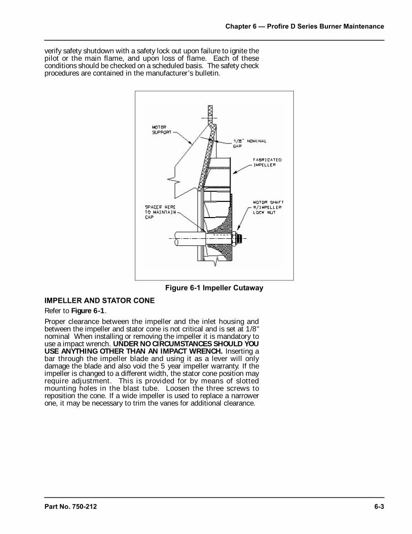
Chapter 6 — Profire D Series Burner Maintenance
verify safety shutdown with a safety lock out upon failure to ignite thepilot or the main flame, and upon loss of flame. Each of theseconditions should be checked on a scheduled basis. The safety checkprocedures are contained in the manufacturer’s bulletin.
IMPELLER AND STATOR CONE
Refer to Figure 6-1. Proper clearance between the impeller and the inlet housing andbetween the impeller and stator cone is not critical and is set at 1/8"nominal When installing or removing the impeller it is mandatory touse a impact wrench. UNDER NO CIRCUMSTANCES SHOULD YOUUSE ANYTHING OTHER THAN AN IMPACT WRENCH. Inserting abar through the impeller blade and using it as a lever will onlydamage the blade and also void the 5 year impeller warranty. If theimpeller is changed to a different width, the stator cone position mayrequire adjustment. This is provided for by means of slottedmounting holes in the blast tube. Loosen the three screws toreposition the cone. If a wide impeller is used to replace a narrowerone, it may be necessary to trim the vanes for additional clearance.
Figure 6-1 Impeller Cutaway
Part No. 750-212 6-3
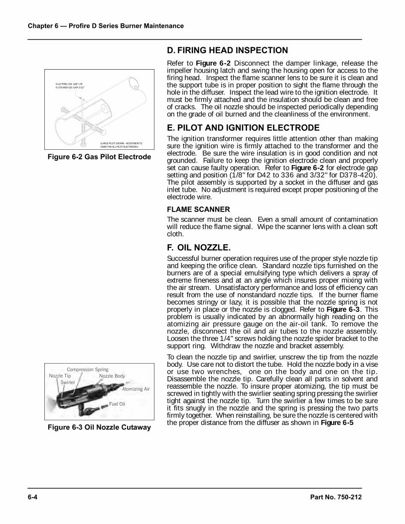
Chapter 6 — Profire D Series Burner Maintenance
6-4
D. FIRING HEAD INSPECTION
Refer to Figure 6-2 Disconnect the damper linkage, release theimpeller housing latch and swing the housing open for access to thefiring head. Inspect the flame scanner lens to be sure it is clean andthe support tube is in proper position to sight the flame through thehole in the diffuser. Inspect the lead wire to the ignition electrode. Itmust be firmly attached and the insulation should be clean and freeof cracks. The oil nozzle should be inspected periodically dependingon the grade of oil burned and the cleanliness of the environment.
E. PILOT AND IGNITION ELECTRODE
The ignition transformer requires little attention other than makingsure the ignition wire is firmly attached to the transformer and theelectrode. Be sure the wire insulation is in good condition and notgrounded. Failure to keep the ignition electrode clean and properlyset can cause faulty operation. Refer to Figure 6-2 for electrode gapsetting and position (1/8" for D42 to 336 and 3/32" for D378-420).The pilot assembly is supported by a socket in the diffuser and gasinlet tube. No adjustment is required except proper positioning of theelectrode wire.
FLAME SCANNER
The scanner must be clean. Even a small amount of contaminationwill reduce the flame signal. Wipe the scanner lens with a clean softcloth.
F. OIL NOZZLE.
Successful burner operation requires use of the proper style nozzle tipand keeping the orifice clean. Standard nozzle tips furnished on theburners are of a special emulsifying type which delivers a spray ofextreme fineness and at an angle which insures proper mixing withthe air stream. Unsatisfactory performance and loss of efficiency canresult from the use of nonstandard nozzle tips. If the burner flamebecomes stringy or lazy, it is possible that the nozzle spring is notproperly in place or the nozzle is clogged. Refer to Figure 6-3. Thisproblem is usually indicated by an abnormally high reading on theatomizing air pressure gauge on the air-oil tank. To remove thenozzle, disconnect the oil and air tubes to the nozzle assembly.Loosen the three 1/4" screws holding the nozzle spider bracket to thesupport ring. Withdraw the nozzle and bracket assembly.
To clean the nozzle tip and swirlier, unscrew the tip from the nozzlebody. Use care not to distort the tube. Hold the nozzle body in a viseor use two wrenches, one on the body and one on the tip.Disassemble the nozzle tip. Carefully clean all parts in solvent andreassemble the nozzle. To insure proper atomizing, the tip must bescrewed in tightly with the swirlier seating spring pressing the swirliertight against the nozzle tip. Turn the swirlier a few times to be sureit fits snugly in the nozzle and the spring is pressing the two partsfirmly together. When reinstalling, be sure the nozzle is centered withthe proper distance from the diffuser as shown in Figure 6-5
Figure 6-2 Gas Pilot Electrode
Figure 6-3 Oil Nozzle Cutaway
SwirlerNozzle Tip
Compression SpringNozzle Body
Fuel Oil
Atomizing Air
Part No. 750-212
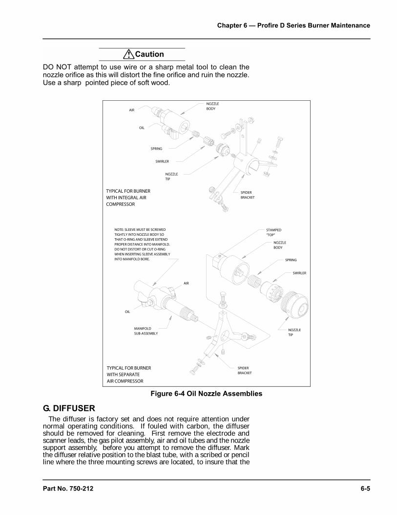
Chapter 6 — Profire D Series Burner Maintenance
! Caution
DO NOT attempt to use wire or a sharp metal tool to clean thenozzle orifice as this will distort the fine orifice and ruin the nozzle.Use a sharp pointed piece of soft wood.
G. DIFFUSER
The diffuser is factory set and does not require attention undernormal operating conditions. If fouled with carbon, the diffusershould be removed for cleaning. First remove the electrode andscanner leads, the gas pilot assembly, air and oil tubes and the nozzlesupport assembly, before you attempt to remove the diffuser. Markthe diffuser relative position to the blast tube, with a scribed or pencilline where the three mounting screws are located, to insure that the
Figure 6-4 Oil Nozzle Assemblies
Part No. 750-212 6-5
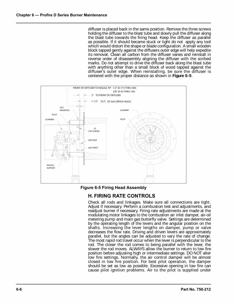
Chapter 6 — Profire D Series Burner Maintenance
diffuser is placed back in the same position. Remove the three screwsholding the diffuser to the blast tube and slowly pull the diffuser alongthe blast tube towards the firing head. Keep the diffuser as parallelas possible. If it should became stuck or tight do not apply any toolwhich would distort the shape or blade configuration. A small woodenblock tapped gently against the diffusers outer edge will help expediteits removal. Clean all carbon from the diffuser vanes and reinstall inreverse order of disassembly aligning the diffuser with the scribedmarks. Do not attempt to drive the diffuser back along the blast tubewith anything other than a small block of wood tapped against thediffuser's outer edge. When reinstalling, be sure the diffuser iscentered with the proper distance as shown in Figure 6-5.
H. FIRING RATE CONTROLS
Check all rods and linkages. Make sure all connections are tight.Adjust if necessary. Perform a combustion test and adjustments, andreadjust burner if necessary. Firing rate adjustments are made at themodulating motor linkages to the combustion air inlet damper, air-oilmetering pump and main gas butterfly valve. Settings are determinedby the operating length of the levers and the angular position on theshafts. Increasing the lever lengths on damper, pump or valvedecreases the flow rate. Driving and driven levers are approximatelyparallel, but the angles can be adjusted to vary the rate of change.The most rapid rod travel occur when the lever is perpendicular to therod. The closer the rod comes to being parallel with the lever, theslower the rod moves. ALWAYS allow the burner to return to low fireposition before adjusting high or intermediate settings. DO NOT alterlow fire settings. Normally, the air control damper will be almostclosed in low fire position. For best pilot operation, the dampershould be set as low as possible. Excessive opening in low fire cancause pilot ignition problems. Air to the pilot is supplied under
Figure 6-5 Firing Head Assembly
6-6 Part No. 750-212
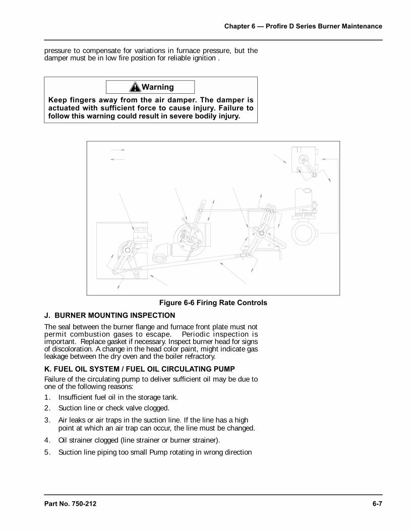
Chapter 6 — Profire D Series Burner Maintenance
pressure to compensate for variations in furnace pressure, but thedamper must be in low fire position for reliable ignition .
J. BURNER MOUNTING INSPECTION
The seal between the burner flange and furnace front plate must notpermit combustion gases to escape. Periodic inspection isimportant. Replace gasket if necessary. Inspect burner head for signsof discoloration. A change in the head color paint, might indicate gasleakage between the dry oven and the boiler refractory.
K. FUEL OIL SYSTEM / FUEL OIL CIRCULATING PUMP
Failure of the circulating pump to deliver sufficient oil may be due toone of the following reasons:1. Insufficient fuel oil in the storage tank.2. Suction line or check valve clogged.
3. Air leaks or air traps in the suction line. If the line has a high point at which an air trap can occur, the line must be changed.
4. Oil strainer clogged (line strainer or burner strainer).
5. Suction line piping too small Pump rotating in wrong direction
! Warning
Keep fingers away from the air damper. The damper isactuated with sufficient force to cause injury. Failure tofollow this warning could result in severe bodily injury.
Figure 6-6 Firing Rate Controls
Part No. 750-212 6-7

Chapter 6 — Profire D Series Burner Maintenance
6-8
6. Three phase pump motor operating on single phase because of fuse failure.
7. Low voltage applied to pump motor.
Notice
Heavy fuel oil sometimes will not leak out through a suction linejoint when the burner is idle, but the same joint may allow airleakage inward when a vacuum is created in the line by pumpaction. The cause of a pulsating burner fire can often be traceddirectly to air leakage in the oil suction line. Always be sure suctionline joints are absolutely air tight.
AIR-OIL METERING PUMP
Both the integral air-oil metering pump for light oil and the heavy oilmetering pump, are precisely fitted units employing a seal on theshaft to prevent oil leakage. Internal wear can take place due to dirtin the oil and may in time result in excessive clearances, reducingpump capacity. Once adjusted, the pump will continue to operatewith a minimum of readjustment. If burner failure appears to becaused by the metering pump, check the following:1. See that the oil is at sufficient level in both fuel oil tank and air-
oil tank on burner.2. Make sure all valves between the fuel oil tank and the burner are
open.
3. Be sure the oil suction line is not air bound and check the suction line strainer.
4. Check the low fire setting of the metering pump to be sure it has not been disturbed.
5. Make sure the pump turns freely.
6. Inspect the burner oil nozzle for clogging.
Whenever an oil metering pump fails to deliver full capacity orpressure, order a replacement pump at once and return the old pumpfor repair or exchange (where allowed).
PRIMARY AIR PUMP OR COMPRESSOR
The air compressor itself requires little maintenance, however its lifeis dependent upon sufficient clean, cool lubricating oil. The oil levelin the air-oil tank must be checked regularly. Lack of oil will damagethe compressor. Disassembly or field repairs to the air compressorare not recommended. Check the air-oil tank sight glass for proper oillevel. The level should be kept at midpoint up the glass. Thecompressor rotor must turn freely. All tube connections must be airtight.
Part No. 750-212
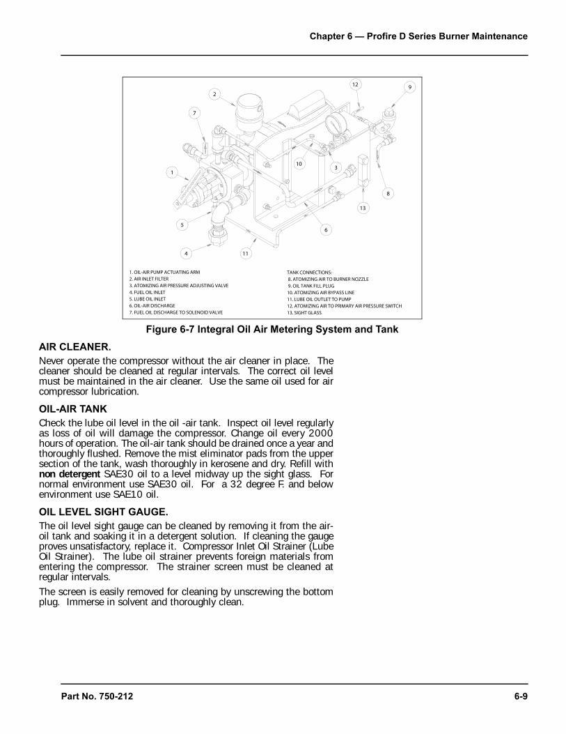
Chapter 6 — Profire D Series Burner Maintenance
AIR CLEANER.
Never operate the compressor without the air cleaner in place. Thecleaner should be cleaned at regular intervals. The correct oil levelmust be maintained in the air cleaner. Use the same oil used for aircompressor lubrication.
OIL-AIR TANK
Check the lube oil level in the oil -air tank. Inspect oil level regularlyas loss of oil will damage the compressor. Change oil every 2000hours of operation. The oil-air tank should be drained once a year andthoroughly flushed. Remove the mist eliminator pads from the uppersection of the tank, wash thoroughly in kerosene and dry. Refill withnon detergent SAE30 oil to a level midway up the sight glass. Fornormal environment use SAE30 oil. For a 32 degree F. and belowenvironment use SAE10 oil.
OIL LEVEL SIGHT GAUGE.
The oil level sight gauge can be cleaned by removing it from the air-oil tank and soaking it in a detergent solution. If cleaning the gaugeproves unsatisfactory, replace it. Compressor Inlet Oil Strainer (LubeOil Strainer). The lube oil strainer prevents foreign materials fromentering the compressor. The strainer screen must be cleaned atregular intervals.The screen is easily removed for cleaning by unscrewing the bottomplug. Immerse in solvent and thoroughly clean.
Figure 6-7 Integral Oil Air Metering System and Tank
Part No. 750-212 6-9
Chapter 6 — Profire D Series Burner Maintenance
Maintenance consists primarily of removing the heating element fromthe manifold and scraping any accumulation of carbonized oil orsludge deposits from the heat exchange surfaces.Before breaking electrical connections to the heating elements, markall wires and terminals to assure correct replacement of wires.Periodic cleaning is necessary to prevent over heating or burn out ofthe elements. If operation of the heater becomes sluggish, examinethe elements and clean as required.Inspect the manifold each time the heater is removed. Flush allaccumulated sludge and sediment before reinstalling the heater.Heater must be full of oil before power is turned on.
OIL STRAINERS
Oil strainers should be cleaned frequently to maintain a free and fullflow of fuel. The strainer screen must be removed and cleaned atregular intervals. The screen should be removed and clean thoroughlyby immersing it in solvent and blowing it dry with compressed air.Light oil strainers should be cleaned each month. Heavy oil strainersshould be checked and cleaned as often as the experience indicatesthe necessity.
I. GAS SYSTEM
MOTORIZED MAIN GAS VALVES
Should the valve fail to operate, check for voltage at the valve. Makecertain that the main shutoff cock is closed prior to testing. Theactuator is not field repairable nor should it be disassembled. Replacethe actuator if valve fails to operate. After replacement, cycle thevalve with the fuel shutoff to determine that it opens and closes. Ifthe valve has a visual indicator, observe its position for correctoperation.
SOLENOID VALVES
A slight hum from the solenoid is normal when the coil is energized.Should the valve fail to operate, check that there is voltage at thevalve coil. If there is no voltage at coil, check for loose wiringconnections. If there is proper voltage at the valve coil and the valvestill fails to open, replace the coil. Refer to manufacturers bulletin forcorrect procedure in coil replacement.Should it become necessary to replace the complete valve, be surethat the flow is in the direction of the arrow on the body.Test for gas leaks and check valve action several times to ensureproper operation before attempting to relight burner.
J. ELECTRICAL SYSTEM
Because of the many types of flame safeguard systems applicable tothis equipment, complete descriptions of all D/Series burner electricalsystems are beyond the scope of this manual. An individual electricalschematic drawing is shipped with each burner and completeoperation and troubleshooting instructions are available from thevarious flame safeguard system manufacturers
ELECTRIC MOTORS
Motor supply voltage must not vary more than 10 percent fromnameplate ratings. At initial start-up and at least once a year
6-10 Part No. 750-212
Chapter 6 — Profire D Series Burner Maintenance
thereafter, check the motor current with a meter while the burner isin high fire position. If the reading exceeds the nameplate rating plusservice factor, determine the cause and correct it immediately. Industy locations, clean the motor regularly to assure adequate cooling.Lubricate in accordance with the manufacturers instructions.
K. EXTENDED SHUTDOWN
When shutting down the burner for an extended period of time, theoperator should use the following general guidelines to protect theburner from its surrounding elements. This will add to the operatinglife of the burner.1. Turn the main electrical disconnect switch to the burner to OFF.2. Close all main fuel valves.
3. If the burner operates in a damp environment, cover it with plastic to protect all electrical components from moisture. Remove the flame safeguard control and store in a dry atmosphere.
L. TROUBLESHOOTING
The points set forth under each heading are briefly, possible causes,suggestions or clues to simplify locating the source of the trouble.Methods of correcting the trouble, once it has been identified, may befound elsewhere in this manual.If the burner will not start or operate properly, the trouble shootingSection should be referred to for assistance in pinpointing problemsthat may be not readily apparent.The program relay has the capability to self-diagnose and to displaya code or message that indicates the failure condition. Refer to thecontrol bulletin for specifics and suggested remedies.Familiarity with the programmer and other controls in the system maybe obtained by studying the contents of this manual. Knowledge of
! Warning
TROUBLE SHOOTING SHOULD BE PERFORMED ONLY BYPERSONNEL WHO ARE FAMILIAR WITH THE EQUIPMENTAND WHO HAVE READ AND UNDERSTOOD THECONTENTS OF THIS MANUAL. FAILURE TO FOLLOWTHESE INSTRUCTIONS COULD RESULT IN SERIOUSPERSONAL INJURY OR DEATH.
! Warning
DISCONNECT AND LOCK OUT THE MAIN POWER SUPPLYIN ORDER TO AVOID THE HAZARD OF ELECTRICALSHOCK. FAILURE TO FOLLOW THESE INSTRUCTIONSCOULD RESULT IN SERIOUS PERSONAL INJURY ORDEATH.
Part No. 750-212 6-11
Chapter 6 — Profire D Series Burner Maintenance
the system and its controls will make trouble shooting that mucheasier. Costly downtimeor delays can be prevented by systematic checks of actual operationagainst the normal sequence to determine the stage at whichperformance deviates from normal. By following a set routine maypossibly eliminate overlooking an obvious condition, often one that isrelatively simple to correct.If an obvious condition is not apparent, check each continuity of eachcircuit with a voltmeter or test lamp. Each circuit can be checked andthe fault isolated and corrected. In most cases circuit checking canbe accomplished between appropriate terminals on the terminalboards in the control cabinet or entrance box. Refer to the wiringschematic supplied for terminal identification.
M.EMERGENCY SHUT DOWN
In case of emergency, shut down the burner by turning the On-Offswitch to the "OFF" position. Turn the fuel selector switch to the OFFposition. Shut off the main manual fuel shut off valves on the fuelsupply line. The unit can also be shut down with the main electricalpower disconnect. Inspect the burner carefully and trouble shootbefore re-starting the unit.
! Warning
THE CAUSE FOR LOSS OF FLAME OR ANY OTHER UNUSUALCONDITION SHOULD BE INVESTIGATED AND CORRECTEDBEFORE ATTEMPTING TO RESTART. FAILURE TO DO SO MAYRESULT IN SERIOUS PERSONAL INJURY OR DEATH.
! Warning
DO NOT REPEAT UNSUCCESSFUL LIGHTING ATTEMPTSWITHOUT RECHECKING THE BURNER AND PILOTADJUSTMENTS. DAMAGE TO THE BOILER OR SERIOUSPERSONAL INJURY OR DEATH MAY RESULT.
! Warning
DO NOT RE-LIGHT THE PILOT OR ATTEMPT TO START THEMAIN BURNER, EITHER OIL OR GAS, IF THE COMBUSTIONCHAMBER IS HOT AND/OR IF GAS OR OIL VAPOR COMBUSTIONGASES ARE PRESENT IN THE FURNACE OR FLUE PASSAGESOR WHEN EXCESS OIL HAS ACCUMULATED. PROMPTLYCORRECT ANY CONDITIONS CAUSING LEAKAGE. FAILURE TOFOLLOW THESE INSTRUCTIONS COULD RESULT IN SERIOUSPERSONAL INJURY OR DEATH.
6-12 Part No. 750-212
Chapter 7
Troubleshooting
Burner Does Not Start . . . . . . . . . . . . . . . . . . . . . . . . . . . . . . 7-3No Ignition . . . . . . . . . . . . . . . . . . . . . . . . . . . . . . . . . . . . . . 7-3Pilot Flame, But No Main Flame . . . . . . . . . . . . . . . . . . . . . . . 7-4Burner Stays in Low Fire . . . . . . . . . . . . . . . . . . . . . . . . . . . . 7-4Shutdown Occurs During Firing . . . . . . . . . . . . . . . . . . . . . . . . 7-4Modulating Motor Does Not Operate . . . . . . . . . . . . . . . . . . . . 7-5
Milwaukee, Wisconsin
www.cleaver-brooks.com

Chapter 7 — Troubleshooting
This chapter assumes that the unit has been properlyinstalled and adjusted, and that it has been running for sometime. It is further assumed that the operator has becomethoroughly familiar with both burner and manual by thistime. The points under each heading are set down briefly aspossible causes, suggestions or clues to simplify locatingthe source of trouble. Methods of correcting the trouble,once it has been identified, may be found elsewhere in thismanual.
If the burner will not start or operate properly, this trouble-shooting chapter should be referred to for assistance inpinpointing problems that may not be readily apparent.
The program relay has the capability to self-diagnose and todisplay a code or message that indicates the failurecondition. Refer to the control bulletin for specifics andsuggested remedies.
Familiarity with the programmer and other controls in thesystem may be obtained by studying the contents of thismanual. Knowledge of the system and its controls will maketroubleshooting much easier. Costly downtime or delays canbe prevented by systematic checks of actual operationagainst the normal sequence to determine the stage at whichperformance deviates from normal. Following a routine maypossibly eliminate overlooking an obvious condition, oftenone that is relatively simple to correct.
If an obvious condition is not apparent, check the continuityof the circuits with a voltmeter or test lamp. Each circuit canbe checked and the fault isolated and corrected. Mostcircuitry checking can be done between appropriateterminals on the terminal boards in the control cabinet orthe entrance box. Refer to the schematic wiring diagram forterminal identification.
! Warning
Troubleshooting should be performed only by personnel who arefamiliar with the equipment and who have read and understandthe contents of this manual. Failure to follow these instructionscould result in serious personal injury or death.
! Warning
Disconnect and lock out the main power supply in order to avoidthe hazard of electrical shock. Failure to follow these instructionscould result in serious personal injury or death.
7-2 Part No. 750-212
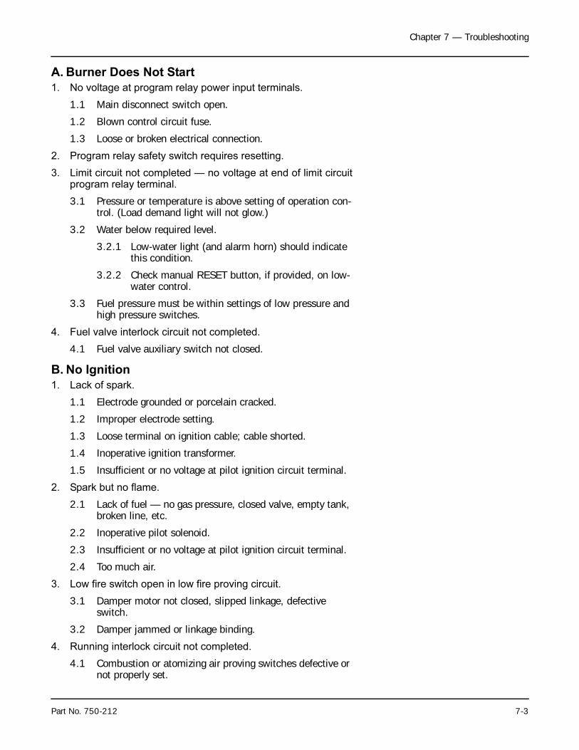
Chapter 7 — Troubleshooting
A. Burner Does Not Start
1. No voltage at program relay power input terminals.
1.1 Main disconnect switch open.
1.2 Blown control circuit fuse.
1.3 Loose or broken electrical connection.
2. Program relay safety switch requires resetting.
3. Limit circuit not completed — no voltage at end of limit circuitprogram relay terminal.
3.1 Pressure or temperature is above setting of operation con-trol. (Load demand light will not glow.)
3.2 Water below required level.
3.2.1 Low-water light (and alarm horn) should indicate this condition.
3.2.2 Check manual RESET button, if provided, on low-water control.
3.3 Fuel pressure must be within settings of low pressure and high pressure switches.
4. Fuel valve interlock circuit not completed.
4.1 Fuel valve auxiliary switch not closed.
B. No Ignition
1. Lack of spark.
1.1 Electrode grounded or porcelain cracked.
1.2 Improper electrode setting.
1.3 Loose terminal on ignition cable; cable shorted.
1.4 Inoperative ignition transformer.
1.5 Insufficient or no voltage at pilot ignition circuit terminal.
2. Spark but no flame.
2.1 Lack of fuel — no gas pressure, closed valve, empty tank, broken line, etc.
2.2 Inoperative pilot solenoid.
2.3 Insufficient or no voltage at pilot ignition circuit terminal.
2.4 Too much air.
3. Low fire switch open in low fire proving circuit.
3.1 Damper motor not closed, slipped linkage, defective switch.
3.2 Damper jammed or linkage binding.
4. Running interlock circuit not completed.
4.1 Combustion or atomizing air proving switches defective or not properly set.
Part No. 750-212 7-3
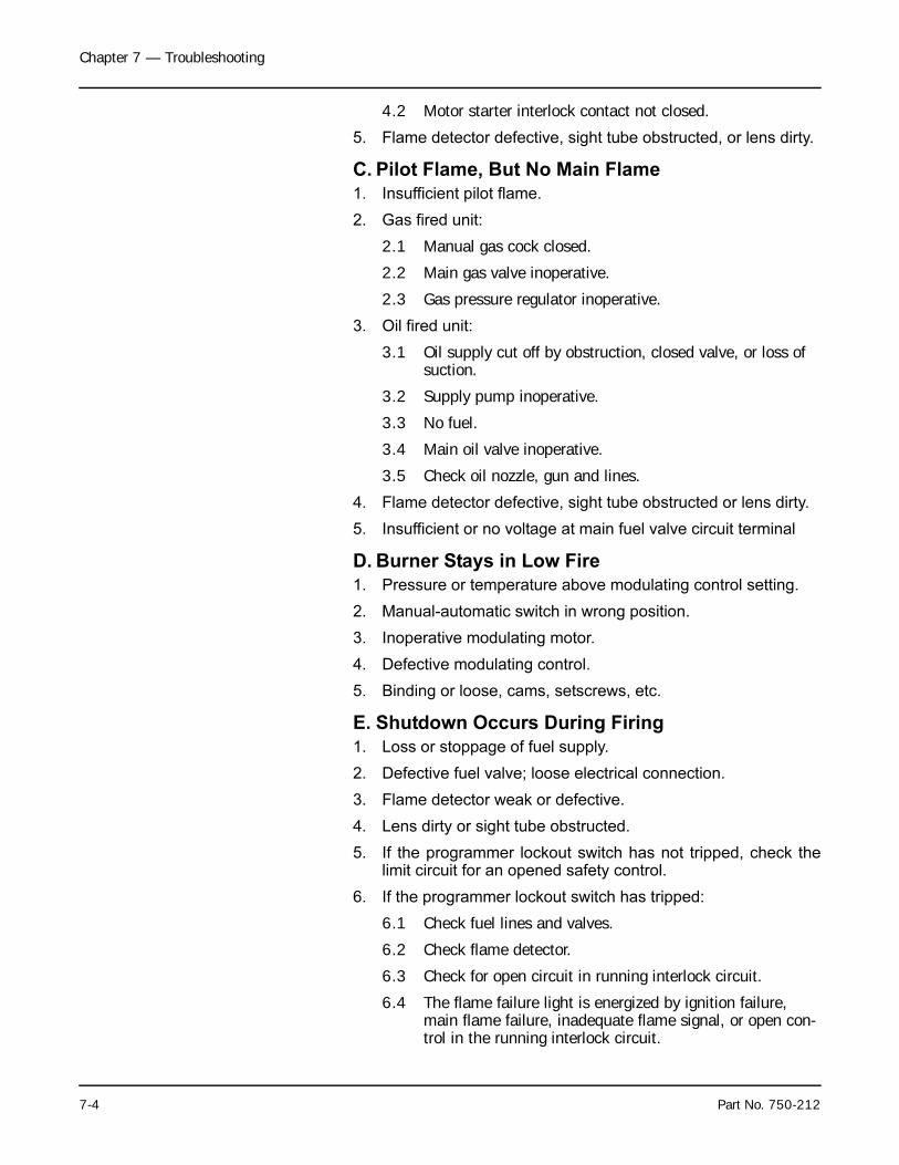
Chapter 7 — Troubleshooting
4.2 Motor starter interlock contact not closed.
5. Flame detector defective, sight tube obstructed, or lens dirty.
C. Pilot Flame, But No Main Flame
1. Insufficient pilot flame.
2. Gas fired unit:
2.1 Manual gas cock closed.
2.2 Main gas valve inoperative.
2.3 Gas pressure regulator inoperative.
3. Oil fired unit:
3.1 Oil supply cut off by obstruction, closed valve, or loss of suction.
3.2 Supply pump inoperative.
3.3 No fuel.
3.4 Main oil valve inoperative.
3.5 Check oil nozzle, gun and lines.
4. Flame detector defective, sight tube obstructed or lens dirty.
5. Insufficient or no voltage at main fuel valve circuit terminal
D. Burner Stays in Low Fire
1. Pressure or temperature above modulating control setting.
2. Manual-automatic switch in wrong position.
3. Inoperative modulating motor.
4. Defective modulating control.
5. Binding or loose, cams, setscrews, etc.
E. Shutdown Occurs During Firing
1. Loss or stoppage of fuel supply.
2. Defective fuel valve; loose electrical connection.
3. Flame detector weak or defective.
4. Lens dirty or sight tube obstructed.
5. If the programmer lockout switch has not tripped, check thelimit circuit for an opened safety control.
6. If the programmer lockout switch has tripped:
6.1 Check fuel lines and valves.
6.2 Check flame detector.
6.3 Check for open circuit in running interlock circuit.
6.4 The flame failure light is energized by ignition failure, main flame failure, inadequate flame signal, or open con-trol in the running interlock circuit.
7-4 Part No. 750-212
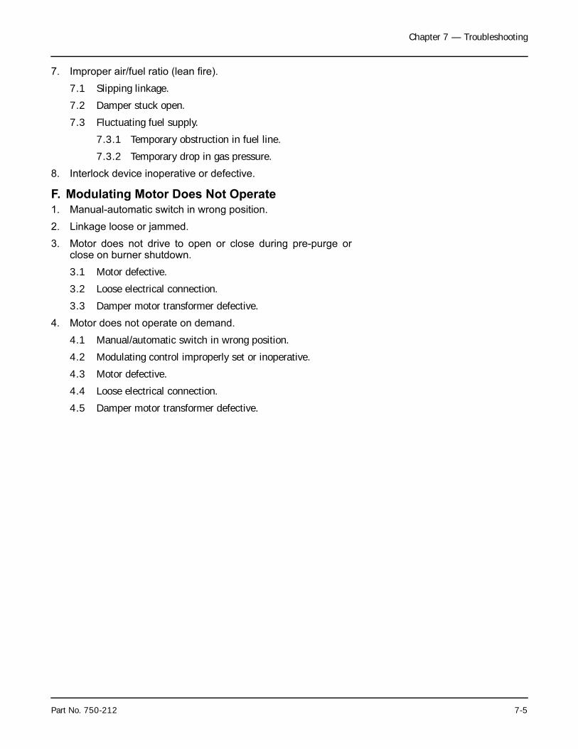
Chapter 7 — Troubleshooting
7. Improper air/fuel ratio (lean fire).
7.1 Slipping linkage.
7.2 Damper stuck open.
7.3 Fluctuating fuel supply.
7.3.1 Temporary obstruction in fuel line.
7.3.2 Temporary drop in gas pressure.
8. Interlock device inoperative or defective.
F. Modulating Motor Does Not Operate
1. Manual-automatic switch in wrong position.
2. Linkage loose or jammed.
3. Motor does not drive to open or close during pre-purge orclose on burner shutdown.
3.1 Motor defective.
3.2 Loose electrical connection.
3.3 Damper motor transformer defective.
4. Motor does not operate on demand.
4.1 Manual/automatic switch in wrong position.
4.2 Modulating control improperly set or inoperative.
4.3 Motor defective.
4.4 Loose electrical connection.
4.5 Damper motor transformer defective.
Part No. 750-212 7-5

Chapter 7 — Troubleshooting
7-6 Part No. 750-212
Notes:
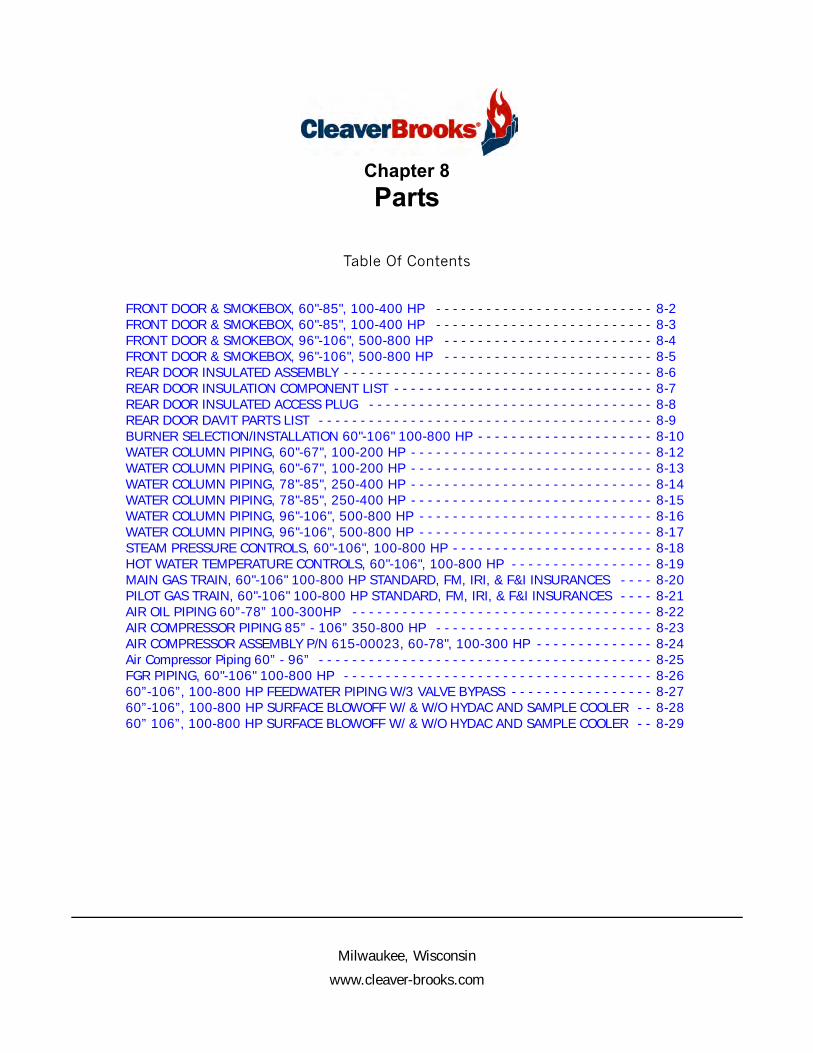
Milwaukee, Wisconsin
www.cleaver-brooks.com
Chapter 8
Parts
Table Of Contents
FRONT DOOR & SMOKEBOX, 60"-85", 100-400 HP - - - - - - - - - - - - - - - - - - - - - - - - - - 8-2FRONT DOOR & SMOKEBOX, 60"-85", 100-400 HP - - - - - - - - - - - - - - - - - - - - - - - - - - 8-3FRONT DOOR & SMOKEBOX, 96"-106", 500-800 HP - - - - - - - - - - - - - - - - - - - - - - - - - 8-4FRONT DOOR & SMOKEBOX, 96"-106", 500-800 HP - - - - - - - - - - - - - - - - - - - - - - - - - 8-5REAR DOOR INSULATED ASSEMBLY - - - - - - - - - - - - - - - - - - - - - - - - - - - - - - - - - - - - - 8-6REAR DOOR INSULATION COMPONENT LIST - - - - - - - - - - - - - - - - - - - - - - - - - - - - - - - 8-7REAR DOOR INSULATED ACCESS PLUG - - - - - - - - - - - - - - - - - - - - - - - - - - - - - - - - - - 8-8REAR DOOR DAVIT PARTS LIST - - - - - - - - - - - - - - - - - - - - - - - - - - - - - - - - - - - - - - - - 8-9BURNER SELECTION/INSTALLATION 60"-106" 100-800 HP - - - - - - - - - - - - - - - - - - - - - 8-10WATER COLUMN PIPING, 60"-67", 100-200 HP - - - - - - - - - - - - - - - - - - - - - - - - - - - - - 8-12WATER COLUMN PIPING, 60"-67", 100-200 HP - - - - - - - - - - - - - - - - - - - - - - - - - - - - - 8-13WATER COLUMN PIPING, 78"-85", 250-400 HP - - - - - - - - - - - - - - - - - - - - - - - - - - - - - 8-14WATER COLUMN PIPING, 78"-85", 250-400 HP - - - - - - - - - - - - - - - - - - - - - - - - - - - - - 8-15WATER COLUMN PIPING, 96"-106", 500-800 HP - - - - - - - - - - - - - - - - - - - - - - - - - - - - 8-16WATER COLUMN PIPING, 96"-106", 500-800 HP - - - - - - - - - - - - - - - - - - - - - - - - - - - - 8-17STEAM PRESSURE CONTROLS, 60"-106", 100-800 HP - - - - - - - - - - - - - - - - - - - - - - - - 8-18HOT WATER TEMPERATURE CONTROLS, 60"-106", 100-800 HP - - - - - - - - - - - - - - - - - 8-19MAIN GAS TRAIN, 60"-106" 100-800 HP STANDARD, FM, IRI, & F&I INSURANCES - - - - 8-20PILOT GAS TRAIN, 60"-106" 100-800 HP STANDARD, FM, IRI, & F&I INSURANCES - - - - 8-21AIR OIL PIPING 60”-78” 100-300HP - - - - - - - - - - - - - - - - - - - - - - - - - - - - - - - - - - - - 8-22AIR COMPRESSOR PIPING 85” - 106” 350-800 HP - - - - - - - - - - - - - - - - - - - - - - - - - - 8-23AIR COMPRESSOR ASSEMBLY P/N 615-00023, 60-78", 100-300 HP - - - - - - - - - - - - - - 8-24Air Compressor Piping 60” - 96” - - - - - - - - - - - - - - - - - - - - - - - - - - - - - - - - - - - - - - - - 8-25FGR PIPING, 60"-106" 100-800 HP - - - - - - - - - - - - - - - - - - - - - - - - - - - - - - - - - - - - - 8-2660”-106”, 100-800 HP FEEDWATER PIPING W/3 VALVE BYPASS - - - - - - - - - - - - - - - - - 8-2760”-106”, 100-800 HP SURFACE BLOWOFF W/ & W/O HYDAC AND SAMPLE COOLER - - 8-2860” 106”, 100-800 HP SURFACE BLOWOFF W/ & W/O HYDAC AND SAMPLE COOLER - - 8-29
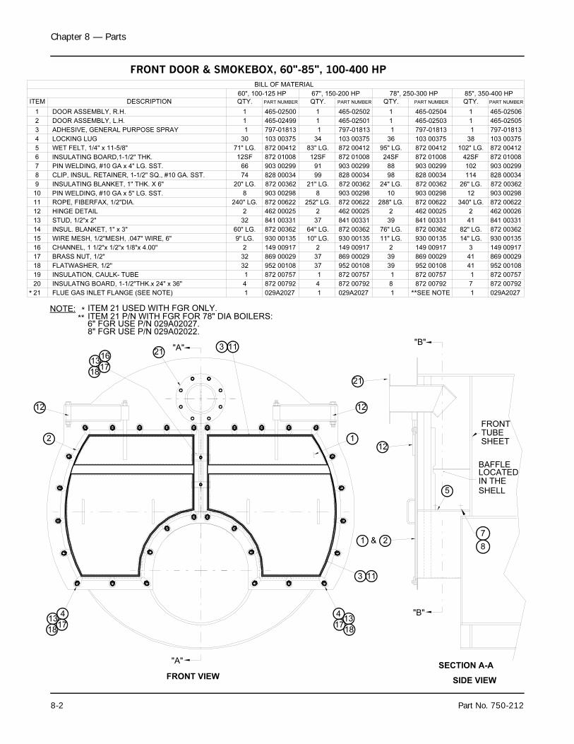
Chapter 8 — Parts
8-2 Part No. 750-212
SECTION A-A
FLUE GAS INLET FLANGE (SEE NOTE)
INSULATION, CAULK- TUBE
INSULATNG BOARD, 1-1/2"THK.x 24" x 36"
WET FELT, 1/4" x 11-5/8"
LOCKING LUG
ADHESIVE, GENERAL PURPOSE SPRAY
FLATWASHER, 1/2"
ROPE, FIBERFAX, 1/2"DIA.
BRASS NUT, 1/2"
CHANNEL, 1 1/2"x 1/2"x 1/8"x 4.00"
HINGE DETAIL
STUD, 1/2"x 2"
CLIP, INSUL. RETAINER, 1-1/2" SQ., #10 GA. SST.
PIN WELDING, #10 GA x 4" LG. SST.
DOOR ASSEMBLY, R.H.
14
20
21
19
18
16
17
15
029A2027
872 00757
872 00792
869 00029
952 00108
149 00917
6
10
12
13
11
8
9
7
5
4
3
2
1
ITEM
462 00025
872 00622
828 00034
903 00299
841 00331
103 00375
872 00412
465-02500
PART NUMBER
797-01813
4
32
32
2
1
30
2
32
74
66
QTY.
BILL OF MATERIAL
DESCRIPTION
240" LG.
71" LG.
1
1
12
2
413
1718
21
2
FRONTTUBESHEET
5
"A"
12
872 00362INSUL. BLANKET, 1" x 3" 60" LG.
8
7
BAFFLELOCATEDIN THE
SHELL
"A"21
WIRE MESH, 1/2"MESH, .047" WIRE, 6"
PIN WELDING, #10 GA x 5" LG. SST.
INSULATING BLANKET, 1" THK. X 6"
930 00135
903 00298
872 00362
9" LG.
8
20" LG.
872 01008INSULATING BOARD,1-1/2" THK. 12SF
1817
413
1
12
FRONT VIEW
&1
465-02499DOOR ASSEMBLY, L.H. 1
* ITEM 21 USED WITH FGR ONLY.
"B"
"B"
SIDE VIEW
60", 100-125 HP
12SF
8
10" LG.
872 00362
872 01008
930 00135
903 00298
QTY.
67", 150-200 HP
34
91
37
2
37
37
99
4
1
2
64" LG.
252" LG.
83" LG.
1
1
1
828 00034
872 00792
SEE NOTE
149 00917
952 00108
872 00757
869 00029
462 00025
872 00362
841 00331
872 00622
872 00412
903 00299
465-02502
797-01813
103 00375
465-02501
PART NUMBER
24SF
10
11" LG.
872 00362
872 01008
930 00135
903 00298
QTY.
78", 250-300 HP
36
88
39
2
39
39
98
8
1
2
76" LG.
288" LG.
95" LG.
1
1
1
828 00034
872 00792
029A2027
149 00917
952 00108
872 00757
869 00029
462 00025
872 00362
841 00331
872 00622
872 00412
903 00299
465-02504
797-01813
103 00375
465-02503
PART NUMBER
42SF
12
872 00362
872 01008
930 00135
903 00298
QTY.
85", 350-400 HP
38
102
41
2
41
41
114
7
1
3
82" LG.
340" LG.
102" LG.
1
1
1
828 00034
872 00792
029A2027
149 00917
952 00108
872 00757
869 00029
462 00026
872 00362
841 00331
872 00622
872 00412
903 00299
465-02506
797-01813
103 00375
465-02505
PART NUMBER
* **
** ITEM 21 P/N WITH FGR FOR 78" DIA BOILERS:6" FGR USE P/N 029A02027.8" FGR USE P/N 029A02022.
1 1 1 1
21" LG. 24" LG. 26" LG.
14" LG.
18
1317
16
3 11
113
NOTE:
FRONT DOOR & SMOKEBOX, 60"-85", 100-400 HP
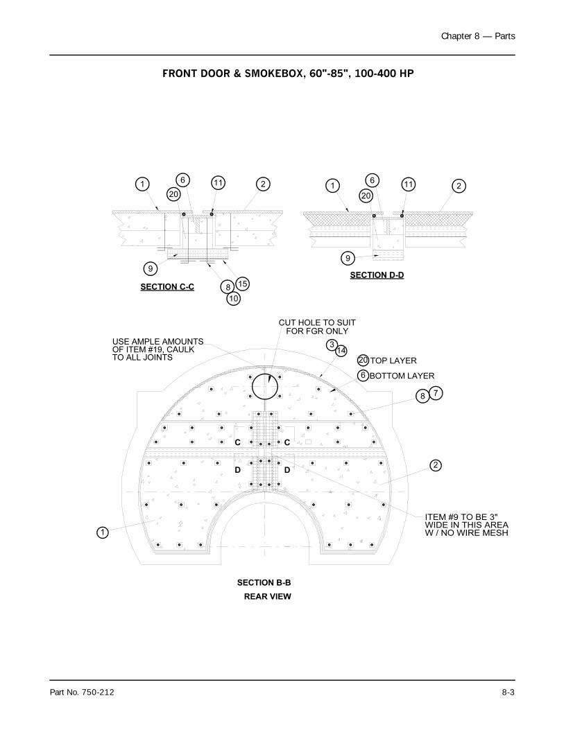
Chapter 8 — Parts
Part No. 750-212 8-3
CUT HOLE TO SUIT
ITEM #9 TO BE 3"
WIDE IN THIS AREA
W / NO WIRE MESH
20
SECTION D-D
9
20
SECTION C-C
1
8 7
9
611
8
10
15
USE AMPLE AMOUNTSOF ITEM #19, CAULKTO ALL JOINTS
1
1
D
C
6 11
D
C
22
2
TOP LAYER
BOTTOM LAYER
314
6
20
SECTION B-B
REAR VIEW
FOR FGR ONLY
FRONT DOOR & SMOKEBOX, 60"-85", 100-400 HP
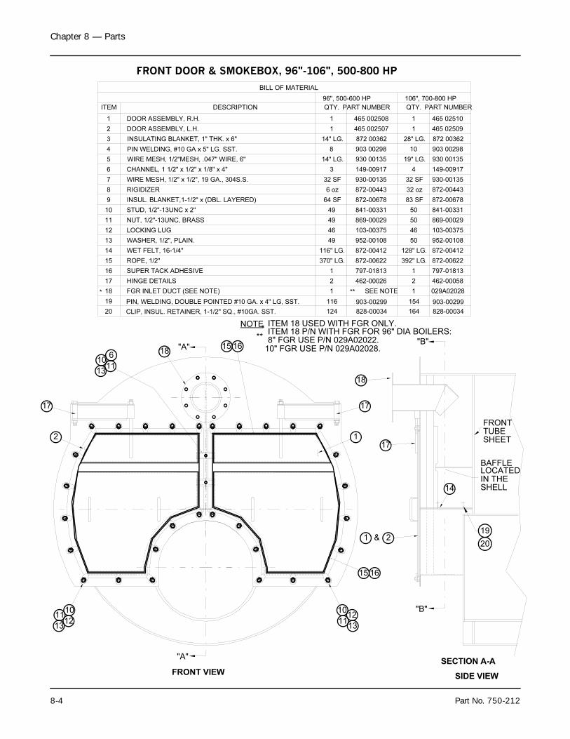
Chapter 8 — Parts
8-4 Part No. 750-212
SECTION A-A
17
2
1011
1213
18
2
FRONTTUBESHEET
14
"A"
17
20
19
BAFFLELOCATEDIN THESHELL
"A"18
1311
1012
1
17
FRONT VIEW
&1
*ITEM 18 USED WITH FGR ONLY.
"B"
"B"
SIDE VIEW
**ITEM 18 P/N WITH FGR FOR 96" DIA BOILERS:
10" FGR USE P/N 029A02028.8" FGR USE P/N 029A02022.
13
1011
6
15 16
1615
NOTE
PIN WELDING, #10 GA x 5" LG. SST.
WIRE MESH, 1/2"MESH, .047" WIRE, 6"
INSULATING BLANKET, 1" THK. x 6"
FGR INLET DUCT (SEE NOTE)
INSUL. BLANKET,1-1/2" x (DBL. LAYERED)
WIRE MESH, 1/2" x 1/2", 19 GA., 304S.S.
CHANNEL, 1 1/2" x 1/2" x 1/8" x 4"
DOOR ASSEMBLY, R.H.
WASHER, 1/2", PLAIN.
WET FELT, 16-1/4"
HINGE DETAILS
SUPER TACK ADHESIVE
ROPE, 1/2"
NUT, 1/2"-13UNC, BRASS
PIN, WELDING, DOUBLE POINTED #10 GA. x 4" LG, SST.
CLIP, INSUL. RETAINER, 1-1/2" SQ., #10GA. SST.
STUD, 1/2"-13UNC x 2"
903 00298
930 00135
872 00362
SEE NOTE
103-00375
952-00108
462-00026
872-00622
797-01813
872-00412
828-00034
903-00299
869-00029
20
18
19
17
15
16
14
12
13
11
LOCKING LUG
465 002508
149-00917
930-00135
841-00331
872-00678
872-00443
PART NUMBER
9
10
8
6
7
5
3
4
2
ITEM
1
RIGIDIZER
124
116
14" LG.
8
14" LG.
2
370" LG.
1
116" LG.
46
49
49
64 SF
32 SF
QTY.
6 oz
DESCRIPTION
49
3
1
96", 500-600 HP
BILL OF MATERIAL
797-01813
903-00299
828-00034
930 00135
872 00362
903 0029810
154
164
2 462-00058
1
46
50
50
872-00412
872-00622
869-00029
952-00108
103-00375
PART NUMBER
83 SF
50
32 oz
32 SF
4
872-00443
872-00678
841-00331
930-00135
149-00917
106", 700-800 HP
QTY.
1 465 02510
DOOR ASSEMBLY, L.H. 465 0025071 1 465 02509
128" LG.
392" LG.
19" LG.
28" LG.
** 029A02028* 1 1
FRONT DOOR & SMOKEBOX, 96"-106", 500-800 HP
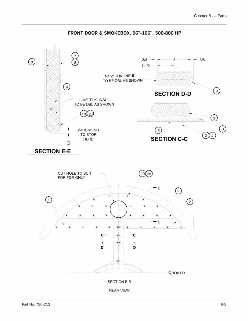
Chapter 8 — Parts
Part No. 750-212 8-5
2
2019
SECTION B-B
BOILERCL
9
9
HERE
1-1/2" THK. INSUL
TO BE DBL AS SHOWN
TO STOP
WIRE MESH
19 20
TO BE DBL AS SHOWN
1-1/2" THK. INSUL
9
8
7
5
2 4
9
3
1
REAR VIEW
CUT HOLE TO SUIT
FOR FGR ONLY
SECTION E-E
3/8
D
C
D
C
E
SECTION C-C
E
SECTION D-D
3/8
1-1/2
3 3/8
9
FRONT DOOR & SMOKEBOX, 96"-106", 500-800 HP
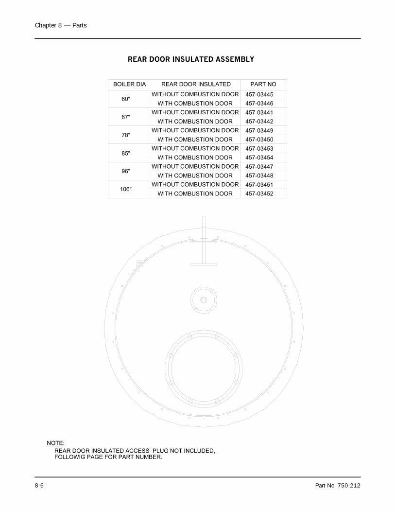
Chapter 8 — Parts
8-6 Part No. 750-212
BOILER DIA REAR DOOR INSULATED PART NO
457-03445WITHOUT COMBUSTION DOOR60"
457-03446WITH COMBUSTION DOOR
457-03442
457-03441WITHOUT COMBUSTION DOOR
WITH COMBUSTION DOOR67"
457-03449
457-03450
WITHOUT COMBUSTION DOOR
WITH COMBUSTION DOOR78"
457-03448
457-03447
457-03453
457-03454
WITHOUT COMBUSTION DOOR
WITH COMBUSTION DOOR
WITHOUT COMBUSTION DOOR
WITH COMBUSTION DOOR
96"
85"
457-03451
457-03452
WITHOUT COMBUSTION DOOR
WITH COMBUSTION DOOR106"
REAR DOOR INSULATED ACCESS PLUG NOT INCLUDED,
NOTE:
FOLLOWIG PAGE FOR PART NUMBER.
REAR DOOR INSULATED ASSEMBLY

Chapter 8 — Parts
Part No. 750-212 8-7
DESCRIPTION60"
ITEM
ADHESIVE
INSULATION
NUT, HEX
RIGIDIZER
BULT, HEX
8
4
6
7
5
3
ROPE GASKET 1/2"
72"
1
350"
38
30
SCREEN58.75"2
1
QTY
36
20
NOTES:
1. ALL SEAMS OF TOP LAYER OF INSULATION (ITEM #5)SHALL BE STAGGERED A MIN. OF 3" FROM ANY
2. COAT INSULATION (ITEM #5) WITH 3200 F RIGIDIZER (ITEM #3)MIXED WITH WATER TO A 50:50 SOLUTION, APPROXIMATELY1/4" DEEP, AFTER SCREEN IS INSTALLED.
SEAMS OF BOTTOM LAYER OF ITEM #5.
BAR, MOUNTING19
CAPSCREW, HEX 610
PIN, WELDING 3511
CLIP, WELD PIN3512
DIA
OZ
FTSQ
67"
44
44
6
1
375"
47
72"
1
FTSQ
30
65.75"
36
OZ
20
DIA
QTY78"
70
70
6
1
432"
71
72"
1
FTSQ
30
76.75"
40
OZ
24
DIA
QTY85"
75
75
6
1
432"
78
72"
1
FTSQ
30
83.75"
40
OZ
24
DIA
QTY96"
80
80
6
1
466"
100
72"
1
FTSQ
30
94.75
46
OZ
30
DIA
QTY106"
90
90
6
1
497"
123
72"
1
FTSQ
30
104.75"
46
OZ
30
DIA
QTY
868-00102
PART NO.
930-00057
872-00443
869-00029
872-00678
797-01813
872-00622
872-00651
004-00026
868-00158
903-00182
828-00039
REAR TUBESHEET
SHELL
4
"A"
"A"
ACCESS PLUGREAR DOOR INSULATTED
OPENINGACCESS
20
SECTION "B-B"
SEE NOTE #1
"B"
"B"
REAR VIEW
SECTION "A-A"
ROPE GASKET 1"
6
5
2
1112
1
4
7
9
4
76
86
6 72
5
10
2
76
6 7
4
1 4
86
REAR DOOR INSULATION COMPONENT LIST
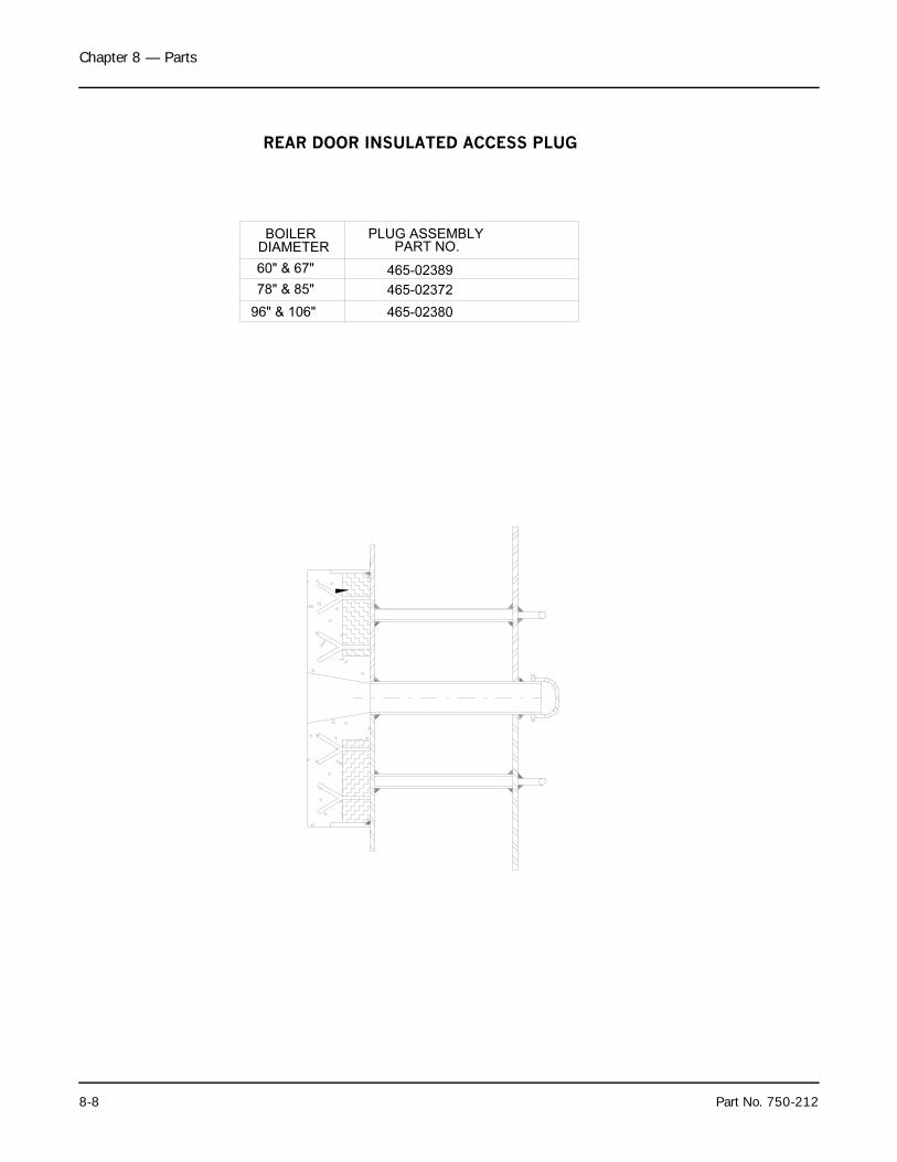
Chapter 8 — Parts
8-8 Part No. 750-212
PART NO.BOILER
465-0238096" & 106"
465-02389
465-0237278" & 85"
60" & 67"
DIAMETER
PLUG ASSEMBLY
REAR DOOR INSULATED ACCESS PLUG
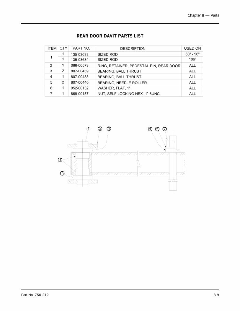
Chapter 8 — Parts
Part No. 750-212 8-9
PART NO. DESCRIPTIONQTYITEM
BEARING, NEEDLE ROLLER
NUT, SELF LOCKING HEX- 1"-8UNC
BEARING, BALL THRUST
BEARING, BALL THRUST
RING, RETAINER, PEDESTAL PIN, REAR DOOR
SIZED ROD
869-001577
807-00440
952-00132
807-00438
807-00439
066-00573
3
5
6
4
2
WASHER, FLAT, 1"
1
2
2
1
1
1
11
135-03633
USED ON
ALL
ALL
ALL
ALL
ALL
ALL
60" - 96"
SIZED ROD135-036341 106"
1 2 3 4 6 7
1
3
REAR DOOR DAVIT PARTS LIST
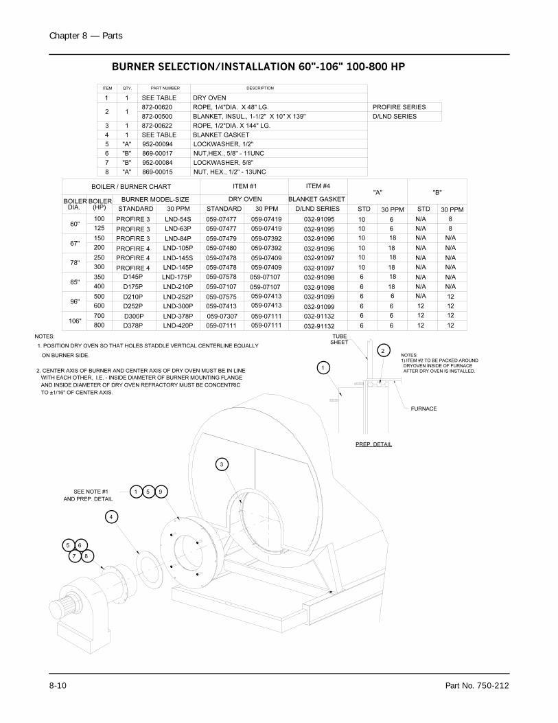
Chapter 8 — Parts
8-10 Part No. 750-212
9
1. POSITION DRY OVEN SO THAT HOLES STADDLE VERTICAL CENTERLINE EQUALLY
NOTES:
3
SEE NOTE #1
AND PREP. DETAIL
PREP. DETAIL
2
BLANKET GASKET
BLANKET, INSUL., 1-1/2" X 10" X 139"
ROPE, 1/2"DIA. X 144" LG.
4
3
2
1
ITEM PART NUMBER
SEE TABLE
SEE TABLE1
872-00500
872-006221
1
QTY.
1 DRY OVEN
DESCRIPTION
LOCKWASHER, 5/8"952-00084
869-00017 NUT,HEX., 5/8" - 11UNC
87
LOCKWASHER, 1/2"
869-00015
952-00094
NUT, HEX., 1/2" - 13UNC"A"
"A"
"B"
"B"
65
51
8
5
6
7
WITH EACH OTHER, I.E. - INSIDE DIAMETER OF BURNER MOUNTING FLANGE
2. CENTER AXIS OF BURNER AND CENTER AXIS OF DRY OVEN MUST BE IN LINE
AND INSIDE DIAMETER OF DRY OVEN REFRACTORY MUST BE CONCENTRIC
TO ±1/16" OF CENTER AXIS.
ON BURNER SIDE.
AFTER DRY OVEN IS INSTALLED. DRYOVEN INSIDE OF FURNACE
NOTES:
1) ITEM #2 TO BE PACKED AROUND
FURNACE
1
TUBE
SHEET
ITEM #1
DRY OVEN
85"
106"
96"
700
800
400
500
600
D378P
D210P
D252P
D175P
LND-420P
LND-378P
LND-300P
LND-210P
059-07111
059-07575
059-07413
059-07107
60"
67"
78"
BOILERDIA.
BOILER / BURNER CHART
BURNER MODEL-SIZE
125
250
300
350
150
200
D145P
BOILER
100
(HP) STANDARD
PROFIRE 3
LND-145S
LND-175P
LND-145P
LND-105P
059-07478
059-07578
059-07478
059-07480
059-07479
30 PPM
LND-54S
LND-63P
STANDARD
059-07477
059-07477
059-07111
6 18 N/A N/A
ITEM #4
BLANKET GASKET
059-07409
059-07107
059-07392
30 PPM
059-07419
059-07419
STD
6 18 N/A
"A"
STD 30 PPM
N/A
30 PPM
"B"
10 6
10
10 18
18
N/A
N/A
N/A
N/A
6 6 12 12
10 6
N/A
N/A
8
8
10 18 N/A N/A
10 N/A N/A
6 N/A
6 6 12 12
126
059-07413
LND-252P
18LND-84P 059-07392
D300P 059-07307
PROFIRE 3
PROFIRE 3
PROFIRE 4
PROFIRE 4
PROFIRE 4 059-07409
059-07107
059-07413
059-07111
6 6 12 12
4
032-91095
032-91095
032-91096
032-91096
032-91097
032-91097
032-91098
032-91098
032-91099
032-91099
032-91132
032-91132
872-00620 ROPE, 1/4"DIA. X 48" LG. PROFIRE SERIES
D/LND SERIES
D/LND SERIES
BURNER SELECTION/INSTALLATION 60"-106" 100-800 HP

Chapter 8 — Parts
Part No. 750-212 8-11
Page Left Blank Intentionally
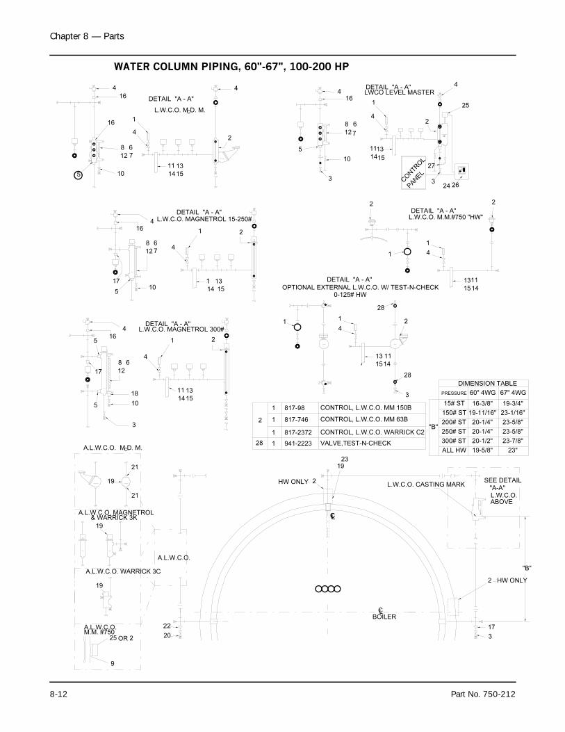
Chapter 8 — Parts
8-12 Part No. 750-212
3
A.L.W.C.O.M.M. #750
9
OR25 2 20
22
A.L.W.C.O. WARRICK 3C
19
& WARRICK 3K
19
A.L.W.C.O. MAGNETROL
A.L.W.C.O.
A.L.W.C.O. M D. M.
19
21
C
21
5
3
101415
BOILER
17
3
CONTROL, L.W.C.O. WARRICK C2
L.W.C.O. CASTING MARK
CL
LCCL
HW ONLY
28 1
12
1
1
23
2
19
CONTROL, L.W.C.O. MM 150B
CONTROL, L.W.C.O. MM 63B
VALVE,TEST-N-CHECK941-2223
817-746
817-2372
817-98
HW ONLY2
"B"
300# ST
200# ST
15# ST
150# ST
250# ST
ALL HW
"B"
SEE DETAIL
L.W.C.O.ABOVE
"A-A"
20-1/4"
20-1/2"
19-5/8"
19-11/16"
20-1/4"
16-3/8"
23-7/8"
23-5/8"
23"
19-3/4"
23-5/8"
23-1/16"
L.W.C.O. MAGNETROL 15-250#DETAIL "A - A"
5
5
17
18
12
68
16
4
21
11
4
13
L.W.C.O. MAGNETROL 300#DETAIL "A - A"
16
1710
712
8 64
1
14
13
15
4
1
5 10
8
12
6
7
4
1
4
16
13
1514
11
L.W.C.O. M D. M.
DETAIL "A - A"
C
24 26
OPTIONAL EXTERNAL L.W.C.O. W/ TEST-N-CHECK
14
2
DETAIL "A - A"
1
13
15
11
0-125# HW
4
1
28
2
PRESSURE
28
2
DIMENSION TABLE
60" 4WG 67" 4WG
1415
L.W.C.O. M.M.#750 "HW"DETAIL "A - A"
1
1
4
1113
2
LWCO LEVEL MASTERDETAIL "A - A"
2
5
4
12
10
3
1514
7
1113
16
8
4
1
6
4
27
CONTROL
PANEL
3
2
25
4
WATER COLUMN PIPING, 60"-67", 100-200 HP
16
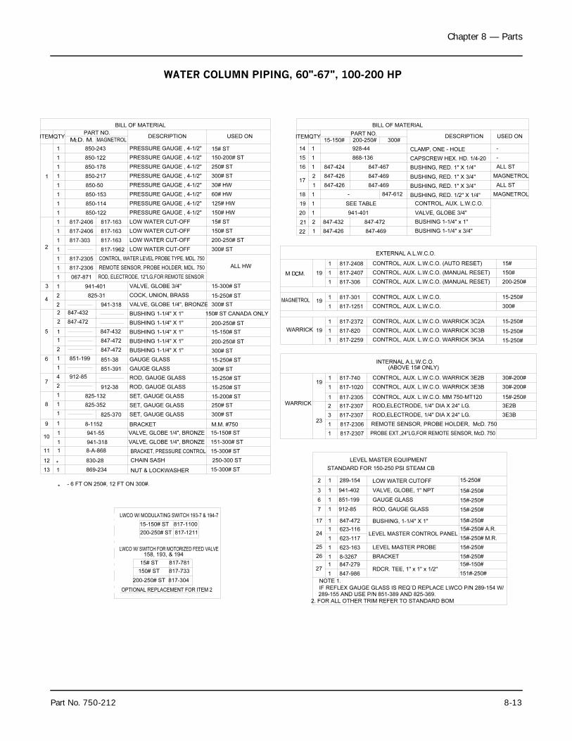
Chapter 8 — Parts
Part No. 750-212 8-13
15-200# ST1
847-986
847-279
289-154
941-402
847-472
912-85
623-163
623-117
623-116
851-199
8-3267
STANDARD FOR 150-250 PSI STEAM CB
IF REFLEX GAUGE GLASS IS REQ`D REPLACE LWCO P/N 289-154 W/289-155 AND USE P/N 851-389 AND 825-369.
2. FOR ALL OTHER TRIM REFER TO STANDARD BOM
817-2307
817-2306
817-2305
817-2307
817-2307
BRACKET, PRESSURE CONTROL
NUT & LOCKWASHER
VALVE, GLOBE 1/4", BRONZE
VALVE, GLOBE 1/4", BRONZE
200-250# ST 817-304
150# ST 817-733
15# ST 817-781
158, 193, & 194LWCO W/ SWITCH FOR MOTORIZED FEED VALVE
200-250# ST 817-1211
15-150# ST 817-1100
LWCO W/ MODULATING SWITCH 193-7 & 194-7
OPTIONAL REPLACEMENT FOR ITEM 2
8-A-868
830-28
869-234
941-318
941-55
8-1152
825-352
- 6 FT ON 250#, 12 FT ON 300#.
825-132
111
13
12
*
1
*
10
9
8
1
1
1
1
1
CHAIN SASH
BRACKET
SET, GAUGE GLASS
SET, GAUGE GLASS
SET, GAUGE GLASS
825-370
NOTE 1.
271
1
24
25
26
1
1
1
17
7
1
1
1
15-300# ST
15-300# ST
250-300 ST
151-300# ST
15-150# ST
M.M. #750
300# ST
250# ST
3
6
2
1
1
1
WARRICK
231
1
3
1
2
15#-250#
3E2B
3E3B
RDCR. TEE, 1" x 1" x 1/2"
BUSHING, 1-1/4" X 1"
LEVEL MASTER CONTROL PANEL
LEVEL MASTER PROBE
ROD, GAUGE GLASS
BRACKET
151#-250#
15#-150#
15#-250#
15#-250#
15#-250#
15#-250# M.R.
15#-250# A.R.
15#-250#
VALVE, GLOBE, 1" NPT
LEVEL MASTER EQUIPMENT
REMOTE SENSOR, PROBE HOLDER, McD. 750
PROBE EXT.,24"LG,FOR REMOTE SENSOR, McD. 750
CONTROL, AUX. L.W.C.O. MM 750-MT120
ROD,ELECTRODE, 1/4" DIA X 24" LG.
ROD,ELECTRODE, 1/4" DIA X 24" LG.
LOW WATER CUTOFF
GAUGE GLASS
15-250#
15#-250#
15#-250#
15-150#
817-1020
817-740
817-2259
847-426
847-432
817-820
817-2372
817-2408
817-301
817-1251
817-306
817-2407
847-426
847-426
847-424
PRESSURE GAUGE , 4-1/2" 300# ST
PRESSURE GAUGE , 4-1/2"
PRESSURE GAUGE , 4-1/2"
PRESSURE GAUGE , 4-1/2"
PRESSURE GAUGE , 4-1/2"
CONTROL, WATER LEVEL PROBE TYPE, MDL. 750
REMOTE SENSOR, PROBE HOLDER, MDL. 750
ROD, ELECTRODE, 12"LG,FOR REMOTE SENSOR
BUSHING 1-1/4" X 1"
BUSHING 1-1/4" X 1"
BUSHING 1-1/4" X 1"
LOW WATER CUT-OFF
VALVE, GLOBE 1/4", BRONZE
LOW WATER CUT-OFF
COCK, UNION, BRASS
BUSHING 1-1/4" X 1"
BUSHING 1-1/4" X 1"
LOW WATER CUT-OFF
LOW WATER CUT-OFF
VALVE, GLOBE 3/4"941-401
825-31
1
7
6
1
912-85
2
4
851-1991
2
5
4
3
2 847-432
847-472
1
2
2
1
2
847-472
GAUGE GLASS
ROD, GAUGE GLASS
GAUGE GLASS
ROD, GAUGE GLASS
851-391
912-38
847-472
851-38
847-432
941-318
850-122
850-153
850-217
850-50
850-114
2
817-2305
817-2306
067-8711
1
1
817-2406
817-303
1
1
1
1
817-24061
1
1
1
1
1
817-163
817-1962
817-163
817-163
15-300# ST
150# ST CANADA ONLY
300# ST
300# ST
15-250# ST
15-250# ST
200-250# ST
15-250# ST
15-150# ST
200-250# ST
300# ST
15-250# ST
1
191
1
WARRICK
MAGNETROL
19 1
1
191
1
150# ST
ALL HW
300# ST
200-250# ST
150# HW
60# HW
30# HW
125# HW
15# ST
22
M D. M.C 19
1
1
1
1
21
20
19
17
18
2
1
1
1
2
1
BILL OF MATERIAL
PRESSURE GAUGE , 4-1/2"
PRESSURE GAUGE , 4-1/2"
DESCRIPTION
PRESSURE GAUGE , 4-1/2"
PART NO.
850-243
850-122
850-178
ITEM
1
1
1
CM D. M.QTY
MAGNETROL
250# ST
150-200# ST
15# ST
USED ON ITEM
14
16
15
1
1
1
QTY
30#-200#
30#-200#
15-250#
15-250#
15-250#
15#
15-250#
300#
200-250#
150#
MAGNETROL
MAGNETROL
ALL ST
CONTROL, AUX. L.W.C.O. (MANUAL RESET)
INTERNAL A.L.W.C.O.(ABOVE 15# ONLY)
CONTROL, AUX. L.W.C.O. WARRICK 3E3B
CONTROL, AUX. L.W.C.O. WARRICK 3E2B
CONTROL, AUX. L.W.C.O. WARRICK 3K3A
CONTROL, AUX. L.W.C.O. WARRICK 3C3B
CONTROL, AUX. L.W.C.O. WARRICK 3C2A
CONTROL, AUX. L.W.C.O.
CONTROL, AUX. L.W.C.O.
EXTERNAL A.L.W.C.O.
CONTROL, AUX. L.W.C.O.
BUSHING 1-1/4" x 3/4"
BUSHING 1-1/4" x 1"
VALVE, GLOBE 3/4"
CONTROL, AUX. L.W.C.O. (AUTO RESET)
CONTROL, AUX. L.W.C.O. (MANUAL RESET)
BUSHING, RED. 1" X 3/4"
BUSHING, RED. 1/2" X 1/4"
BUSHING, RED. 1" X 3/4"
847-469
847-472
847-469
847-612
847-469
941-401
SEE TABLE
-
USED ON
ALL ST
BILL OF MATERIAL
CLAMP, ONE - HOLE
BUSHING, RED. 1" X 1/4"
CAPSCREW HEX. HD. 1/4-20
847-467
928-44
868-136
PART NO.200-250# 300#
DESCRIPTION
-
-
WATER COLUMN PIPING, 60"-67", 100-200 HP
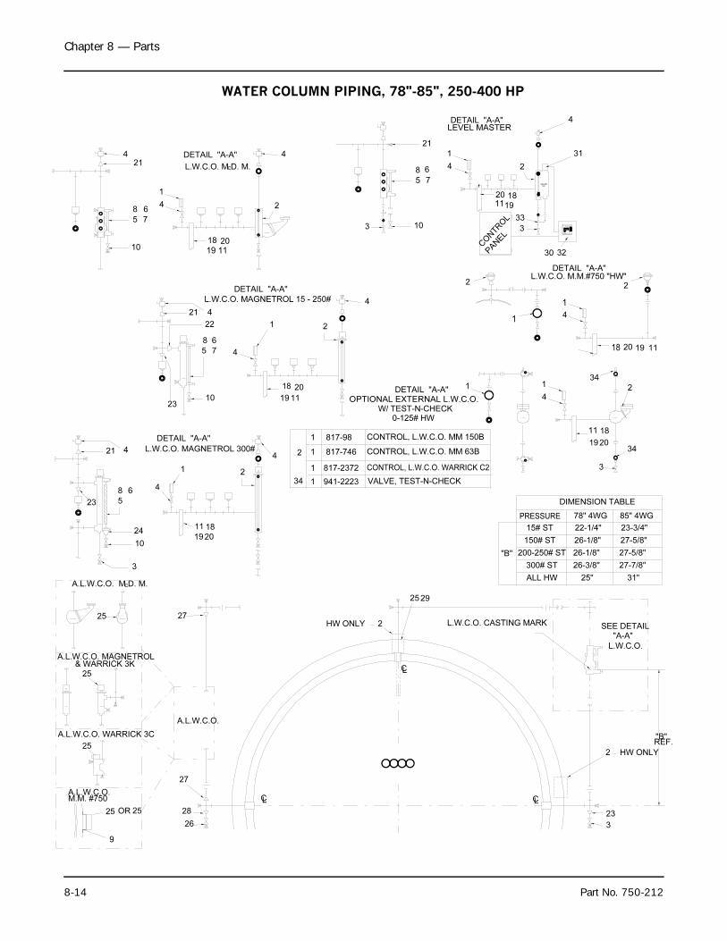
Chapter 8 — Parts
8-14 Part No. 750-212
M.M. #750A.L.W.C.O.
9
25 25OR
26
28
27
A.L.W.C.O. M D. M.
& WARRICK 3KA.L.W.C.O. MAGNETROL
A.L.W.C.O. WARRICK 3C
25
25
A.L.W.C.O.
25
C
3
27
10
24
23
8 6
5
2019
1811
4
1
L.W.C.O. MAGNETROL 300#
DETAIL "A-A"
21 4
2310
5 7
LC LC
3
23
L.W.C.O. CASTING MARK HW ONLY
CL
2
2925
4
2
4
19
18
11
20
VALVE, TEST-N-CHECK
CONTROL, L.W.C.O. MM 63B
CONTROL, L.W.C.O. WARRICK C2
817-746
817-2372
941-22231
2
34
1
1
"B"
CONTROL, L.W.C.O. MM 150B
W/ TEST-N-CHECKOPTIONAL EXTERNAL L.W.C.O.
DETAIL "A-A"
817-981
0-125# HW
1
REF.
HW ONLY2
"B"
26-3/8"
25"
300# ST
ALL HW
"A-A"
L.W.C.O.
SEE DETAIL
27-7/8"
31"
19
78" 4WG
DIMENSION TABLE
26-1/8"
26-1/8"
22-1/4"
200-250# ST
PRESSURE
150# ST
15# ST
85" 4WG
23-3/4"
27-5/8"
27-5/8"
3
2034
4
1 2
11 18
34
18 20 1119
DETAIL "A-A"
L.W.C.O. M D. M.
L.W.C.O. MAGNETROL 15 - 250#
18 2010
22
8 6
21 4
19 11
5 7
8 6
214
1
4
C
DETAIL "A-A"
3
DETAIL "A-A"
1 2
4
2
4
CONTROL
10
2
PANEL
5 7
8 6
21
1119
20 18
LEVEL MASTER
1
4
4
L.W.C.O. M.M.#750 "HW"DETAIL "A-A"
4
1
3
30 32
2
33
2
31
WATER COLUMN PIPING, 78"-85", 250-400 HP
1
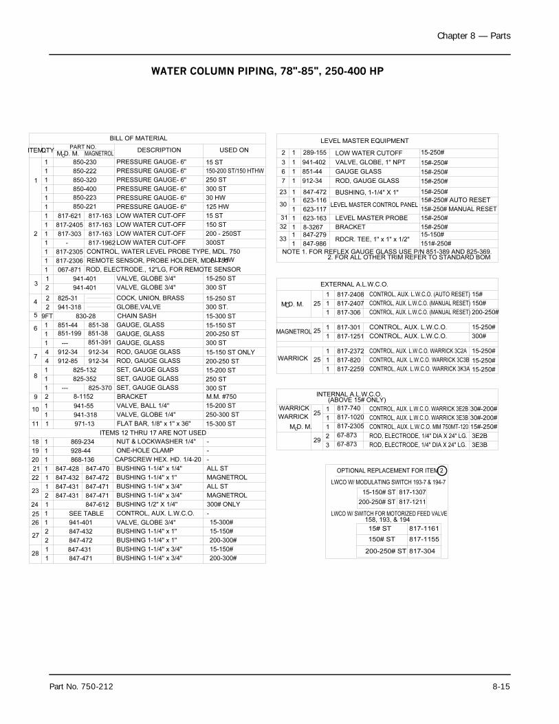
Chapter 8 — Parts
Part No. 750-212 8-15
BILL OF MATERIAL
CONTROL, WATER LEVEL PROBE TYPE, MDL. 750
REMOTE SENSOR, PROBE HOLDER, MDL. 750
ROD, ELECTRODE., 12"LG, FOR REMOTE SENSOR
ITEMS 12 THRU 17 ARE NOT USED
SEE TABLE1
281
227
1
2
26
25
1
847-471
847-432
941-401
847-431
847-472
847-431
847-431
847-428
847-432
23
24 1
2
22
1
1
19 1
21
20
1
1
18 1
847-471
847-472
847-471
847-612
869-234
928-44
847-470
868-136
912-34
912-85
10
11 1
1
9 2
1
18
1
1
74
4
8-1152
971-13
941-318
941-55
825-132
825-352
--- 825-370
912-34
912-34
067-871
825-31
941-318
851-199
851-44
2
61
1
9FT5
1
2
42
3
1
1
830-28
--- 851-391
851-38
851-38
941-401
941-401
817-621
817-303
817-2405
817-2305
817-2306
1
1
1
2
1
1
1
1
1
1
817-163
- 817-1962
817-163
850-221
850-223
850-400
817-163
1
1
1
QTYITEM
1
850-222
850-320
850-230
PART NO.
M D. M.C
MAGNETROL
LWCO W/ MODULATING SWITCH 193-7 & 194-7
LWCO W/ SWITCH FOR MOTORIZED FEED VALVE
OPTIONAL REPLACEMENT FOR ITEM 2
817-306
817-301
817-820
817-740
67-873
67-873
INTERNAL A.L.W.C.O.
817-2305
817-1020
(ABOVE 15# ONLY)
817-1251
817-2372
817-2259
817-2407
817-2408
EXTERNAL A.L.W.C.O.
MAGNETROL
15-150#
15-300#
MAGNETROL
300# ONLY
15-150#
200-300#
200-300#
CONTROL, AUX. L.W.C.O.
BUSHING 1-1/4" x 3/4"
BUSHING 1-1/4" x 3/4"
VALVE, GLOBE 3/4"
BUSHING 1-1/4" x 1"
BUSHING 1-1/4" x 1"
-
NUT & LOCKWASHER 1/4"
BUSHING 1-1/4" x 1/4"
CAPSCREW HEX. HD. 1/4-20
BUSHING 1-1/4" x 3/4"
BUSHING 1-1/4" x 3/4"
BUSHING 1-1/4" x 1"
BUSHING 1/2" X 1/4"
ONE-HOLE CLAMP
ALL ST
ALL ST
-
-
-
293
2
15-250 ST
15-300 ST
15-250 ST
200-250 ST
15-150 ST
M.M. #750
15-200 ST
15-300 ST
250-300 ST
15-200 ST
200-250 ST
15-150 ST ONLY
FLAT BAR, 1/8" x 1" x 36"
SET, GAUGE GLASS
VALVE, BALL 1/4"
VALVE, GLOBE 1/4"
BRACKET
ROD, GAUGE GLASS
SET, GAUGE GLASS
ROD, GAUGE GLASS
SET, GAUGE GLASS
300 ST
250 ST
GLOBE,VALVE
CHAIN SASH
GAUGE, GLASS
GAUGE, GLASS
GAUGE, GLASS
VALVE, GLOBE 3/4"
COCK, UNION, BRASS
VALVE, GLOBE 3/4"
300 ST.
300 ST
300 ST
WARRICK
M D. M.C
WARRICK 125
1
1
WARRICK
1
25 1
1
MAGNETROL1
251
1
M D. M.C 25
1
1
ROD, ELECTRODE, 1/4" DIA X 24" LG.
ROD, ELECTRODE, 1/4" DIA X 24" LG.
817-1211200-250# ST
200-250# ST
158, 193, & 194
150# ST
15# ST
817-304
817-1155
817-1161
15-150# ST 817-1307
3E3B
3E2B
CONTROL, AUX. L.W.C.O. WARRICK 3C3B
CONTROL, AUX. L.W.C.O. WARRICK 3C2A
CONTROL, AUX. L.W.C.O. (MANUAL RESET)
CONTROL, AUX. L.W.C.O. (MANUAL RESET)
CONTROL, AUX. L.W.C.O. (AUTO RESET)
CONTROL, AUX. L.W.C.O. WARRICK 3E2B
CONTROL, AUX. L.W.C.O. WARRICK 3E3B
CONTROL, AUX. L.W.C.O. MM 750MT-120
CONTROL, AUX. L.W.C.O. WARRICK 3K3A
CONTROL, AUX. L.W.C.O.
CONTROL, AUX. L.W.C.O.
15-250#
30#-200#
15#-250#
30#-200#
15-250#
15-250#
300#
15-250#
200-250#
150#
15#
BRACKET
LEVEL MASTER EQUIPMENT
LEVEL MASTER CONTROL PANEL
RDCR. TEE, 1" x 1" x 1/2"
NOTE 1. FOR REFLEX GAUGE GLASS USE P/N 851-389 AND 825-369. 2. FOR ALL OTHER TRIM REFER TO STANDARD BOM
BUSHING, 1-1/4" X 1"
LEVEL MASTER PROBE
GAUGE GLASS
ROD, GAUGE GLASS
VALVE, GLOBE, 1" NPT
LOW WATER CUTOFF
ALL HW
200 - 250ST
150-200 ST/150 HTHW
USED ON
LOW WATER CUT-OFF
LOW WATER CUT-OFF
PRESSURE GAUGE- 6"
LOW WATER CUT-OFF
LOW WATER CUT-OFF
PRESSURE GAUGE- 6"
PRESSURE GAUGE- 6"
300ST
125 HW
150 ST
15 ST
30 HW
300 ST
DESCRIPTION
PRESSURE GAUGE- 6"
PRESSURE GAUGE- 6"
PRESSURE GAUGE- 6" 250 ST
15 ST
30
23
31
32
33
8-32671
847-986
847-279
1
1
623-116
847-472
623-163
623-117
1
1
1
1
3
2
6
7
289-155
941-402
851-44
912-341
1
1
1
15#-250# AUTO RESET
15#-250# MANUAL RESET
15#-250#
151#-250#
15-150#
15#-250#
15#-250#
15-250#
15#-250#
15#-250#
15#-250#
WATER COLUMN PIPING, 78"-85", 250-400 HP
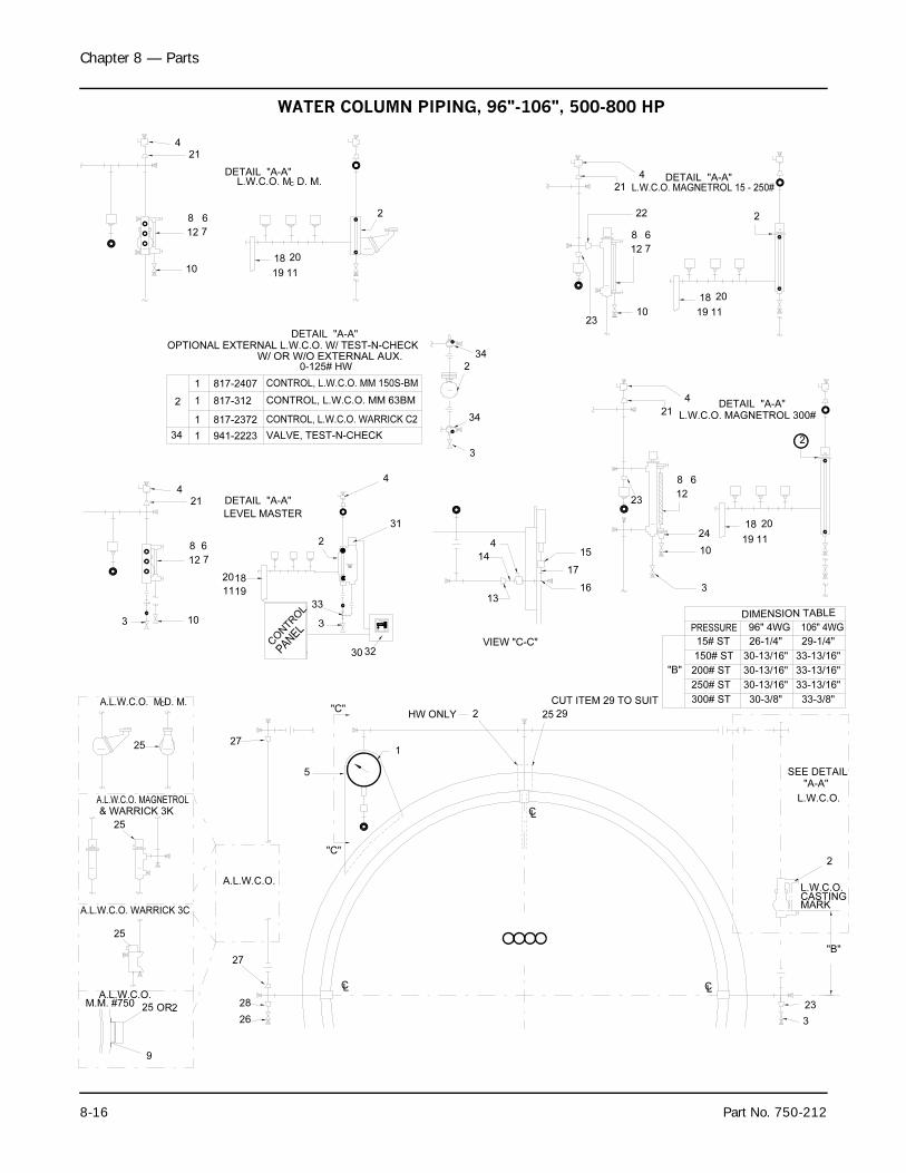
Chapter 8 — Parts
8-16 Part No. 750-212
A.L.W.C.O.
& WARRICK 3K
A.L.W.C.O. WARRICK 3C
A.L.W.C.O. MAGNETROL
25
25
A.L.W.C.O. M D. M.C
25
LL
26
28
27
C
"C"
"C"
27
5
1
CL
C
CUT ITEM 29 TO SUIT
2925
"B"
150# ST
300# ST
250# ST
200# ST
15# ST
DIMENSION TABLE
PRESSURE
29-1/4"
33-13/16"
33-13/16"
33-13/16"
33-3/8"
30-13/16"
30-13/16"
30-13/16"
30-3/8"
26-1/4"
106" 4WG96" 4WG
VIEW "C-C"
3
23
13
16
14
"B"
MARKCASTINGL.W.C.O.
2
"A-A"
L.W.C.O.
SEE DETAIL
4
17
15
23
23
3
24
1019 11
18 20
DETAIL "A-A" L.W.C.O. MAGNETROL 300#
12
68
21
4
10
2
1119
2018
3
PANEL
CONTROL
L.W.C.O. MAGNETROL 15 - 250#DETAIL "A-A"
21
8 6
12 7
22
4
10
2
19 11
2018
DETAIL "A-A"
7
6
12
8
421
L.W.C.O. M D. M.C
2
3230
6
7
10
12
8
1119
2018
421
33
3
2
DETAIL "A-A"
LEVEL MASTER31
4
9
A.L.W.C.O.M.M. #750 OR25 2
2HW ONLY
34
DETAIL "A-A"OPTIONAL EXTERNAL L.W.C.O. W/ TEST-N-CHECK
W/ OR W/O EXTERNAL AUX.
VALVE, TEST-N-CHECK
CONTROL, L.W.C.O. MM 63BM
CONTROL, L.W.C.O. WARRICK C2
CONTROL, L.W.C.O. MM 150S-BM817-2407
817-312
817-2372
941-222334
1
1
1
2 1
0-125# HW
34
3
2
WATER COLUMN PIPING, 96"-106", 500-800 HP
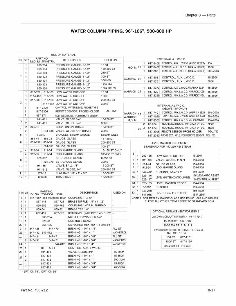
Chapter 8 — Parts
Part No. 750-212 8-17
STEAM ONLY
200-250 ST ONLY
15#-250# MANUAL RESET1 623-117
NOTE 1. FOR REFLEX GAUGE GLASS USE P/N 851-389 AND 825-369.
33
32
847-9861
847-279
623-163
8-32671
1
31 1
2. FOR ALL OTHER TRIM REFER TO STANDARD BOM
RDCR. TEE, 1" x 1" x 1/2"
LEVEL MASTER PROBE
BRACKET
151#-250#
15#-150#
15#-250#
15#-250#
3
STANDARD FOR 150-250 PSI STEAM
825-352
8-3340
851-199
941-401
941-318
941-55
23
30
912-34
847-472
623-1161
1
851-44
7 16 1
289-155
941-402
1
3 1
2
1
4 912-85
1
101
81
74
6
1
1
912-34
1
1
5
851-44
42
2
2 825-31
LEVEL MASTER EQUIPMENT
BUSHING, 1-1/4" X 1"
LEVEL MASTER CONTROL PANEL
ROD, GAUGE GLASSGAUGE GLASS
LOW WATER CUTOFF
VALVE, GLOBE, 1" NPT
VALVE, GLOBE, 1/4"
15#-250# AUTO RESET
15#-250#
15#-250#15#-250#
15#-250#
15-250#
250-300 ST
BRACKET, STEAM GAUGE
VALVE, GLOBE 1/4", BRASS
SET, GAUGE GLASS
ROD, GAUGE GLASS
ROD, GAUGE GLASS
GAUGE, GLASS
SET, GAUGE GLASS
GAUGE, GLASS
VALVE, BALL 1/4"
912-34
825-370
851-38
912-34
851-391
VALVE, GLOBE 3/4"
COCK, UNION, BRASS
GAUGE, GLASS851-38
941-318
0-250 ST
15-200 ST
300 ST
15-150 ST ONLY
200-250 ST
300 ST
15-150 ST
15-250 ST
300 ST
300 ST
941-401
M D. M.
850-172
PART NO.
850-264
850-104
850-150
817-621
817-2405
817-303
* - 9FT. ON 78", 12FT. ON 96"
1
1
12
1
1
1
11
1
1
ITEM QTYC
PRESSURE GAUGE- 8-1/2"
PRESSURE GAUGE- 8-1/2"
PRESSURE GAUGE- 8-1/2"
DESCRIPTION
PRESSURE GAUGE- 8-1/2"
VALVE, GLOBE 3/4"
LOW WATER CUT-OFF
LOW WATER CUT-OFF
LOW WATER CUT-OFF
LOW WATER CUT-OFF
817-163
817-163
817-1962
817-163
MAGNETROL
150 ST
15-250 ST
200-250 ST
300 ST
15 ST
300 ST
150-200 ST
250 ST
USED ON
15 ST
30#-200#1 817-1020 CONTROL, AUX. L.W.C.O. WARRICK 3E3B
200-250# ST 817-1211
15-150# ST 817-1307
LWCO W/ MODULATING SWITCH 193-7 & 194-7
OPTIONAL REPLACEMENT FOR ITEM 2
REMOTE SENSOR, PROBE HOLDER, MDL. 750
PROBE EXT., 36"LG, FOR REMOTE SENSOR, MDL. 750
CONTROL, AUX. L.W.C.O. MM 750 MT-120
ROD,ELECTRODE, 1/4" DIA X 24" LG.
ROD,ELECTRODE, 1/4" DIA X 24" LG.
WARRICK
M D. M.C
29817-2306
817-23831
1
817-2305
67-873
67-873
2
3
1 15#-200#
3E2B
3E3B
LWCO W/ SWITCH FOR MOTORIZED FEED VALVE
200-250# ST 817-304
150# ST 817-1155
15# ST 817-1161
158, 193, & 194
CONTROL, AUX. L.W.C.O. WARRICK 3E2B
CONTROL, AUX. L.W.C.O. WARRICK 3K3A
CONTROL, AUX. L.W.C.O.
BUSHING 1-1/4" x 3/4"
BUSHING 1-1/4" x 1"
BUSHING 1-1/4" x 1"
BUSHING 1-1/4" x 3/4"
VALVE, GLOBE 3/4"
CONTROL, AUX. L.W.C.O. WARRICK 3C3B
CONTROL, AUX. L.W.C.O. WARRICK 3C2A
CONTROL, AUX. L.W.C.O. (AUTO RESET)
BUSHING 1/2" X 1/4"
BUSHING 1-1/4" x 3/4"
BUSHING 1-1/4" x 1"
CONTROL, AUX. L.W.C.O.
CONTROL, AUX. L.W.C.O.
CONTROL, AUX. L.W.C.O. (MANUAL RESET)
BUSHING 1-1/4" x 3/4"
CONTROL, AUX. L.W.C.O. (MANUAL RESET)
CAPSCREW HEX. HD. 1/4-20 x 3/4"
BUSHING 1-1/4" x 1/4"
ONE-HOLE CLAMP
INTERNAL A.L.W.C.O.(ABOVE 15# ONLY)
EXTERNAL A.L.W.C.O.
WARRICK 25
WARRICK 25
MAGNETROL 25
M D. M.C 25
817-7401
817-2259
817-820
817-2372
1
1
1
1 817-306
817-301
817-1251
1
1
817-2408
817-2407
1
1
SEE TABLE
941-401
847-431
847-472
847-432
847-471
847-431
847-432
847-431
847-428
272
128
1
2
26 1
25 1
2
24 1
231
21
22 1
1
20
19
1
1
847-612
847-471
847-471
847-470
847-472
868-136
928-44
30#-200#
15-250#
15-250#
15-250#
200-250#
15-250#
300#
150#
15#
15-300#
200-300#
15-150#
15-150#
200-300#
MAGNETROL
MAGNETROL
MAGNETROL
ALL ST
ALL ST
-
-
FLAT BAR, 1/8" x 1" x 36"
NUT & LOCKWASHER 1/4"
COUPLING 1" X 1/4"
BRASS NPL. (X-HEAVY) 1/4" x 1-1/2"
BRASS TEE 1/4"
COUPLING 1/4" R.H. THREAD
BRASS NIPPLE, 1/4" x 1-1/2"
847-1687
15-150#QTYITEM
115
117
18 1
16 1
14 1
13 1
*12
111
858-1009
857-676
859-32
858-768
857-726
858-856
869-234
857-452
859-54
858-1009
200-250#
857-448
300#PART NO.
830-28
971-13
CHAIN SASH
USED ONDESCRIPTION
-
-
-
-
-
-
15-300 ST
15-300 ST
-
BILL OF MATERIAL
30# HWPRESSURE GAUGE- 8-1/2"850-1011
PRESSURE GAUGE- 8-1/2"1 850-103 125# HW
PRESSURE GAUGE- 8-1/2"1 850-104 150# HTHW
ROD, ELECTRODE., FOR REMOTE SENSOR
REMOTE SENSOR, PROBE HOLDER
CONTROL, WATER LEVEL PROBE TYPE
1 067-871
1
1
817-2306
817-2305
ALL HW
WATER COLUMN PIPING, 96"-106", 500-800 HP
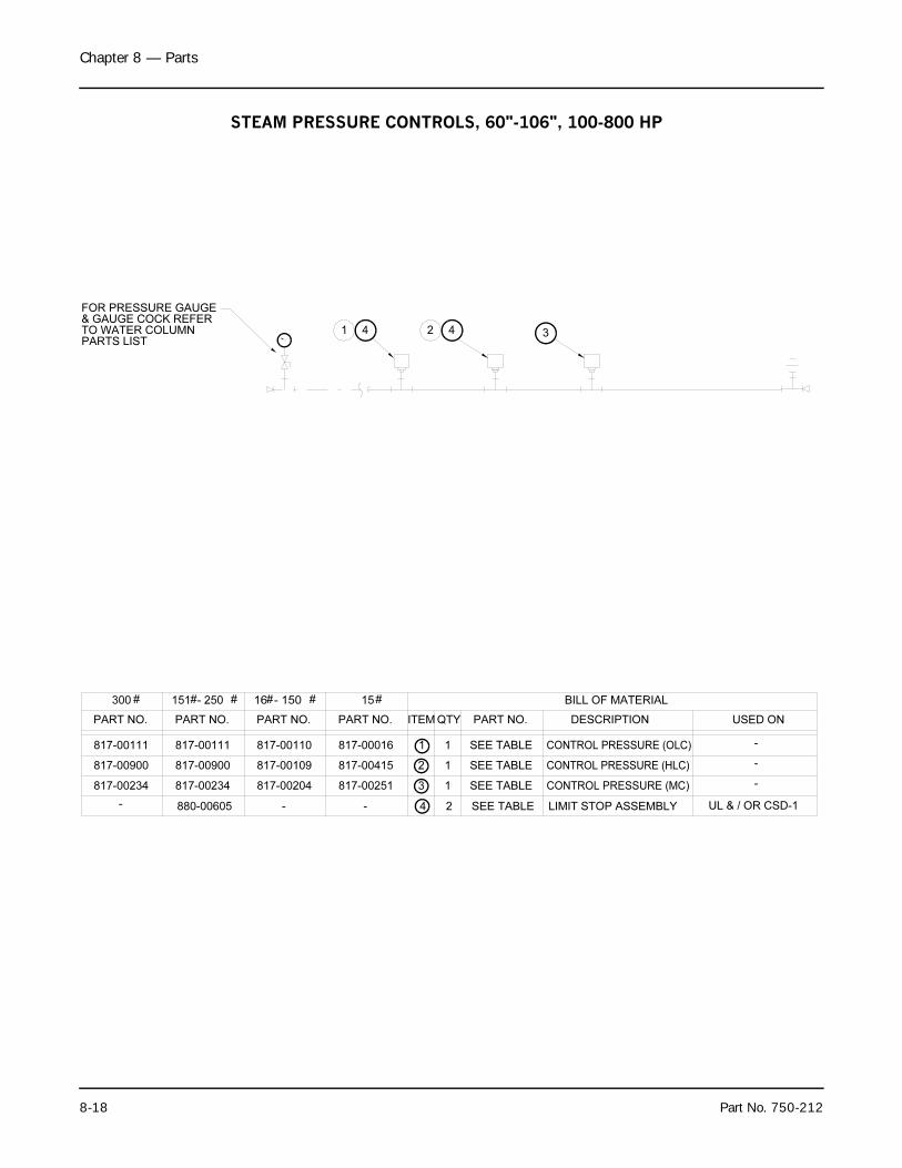
Chapter 8 — Parts
8-18 Part No. 750-212
1 2 3
CONTROL PRESSURE (MC)
CONTROL PRESSURE (HLC)
SEE TABLE
SEE TABLE
817-00016817-00110817-00111817-00111
PART NO.
300
PART NO.
151 - 250
PART NO.
16 - 150 15
PART NO.
SEE TABLE
ITEM QTY PART NO. DESCRIPTION
1 1 CONTROL PRESSURE (OLC)
2
3 1
BILL OF MATERIAL
817-00234
817-00900 817-00900
817-00234 817-00204
817-00109
817-00251
817-00415 1
USED ON
-
# # # # # #
4 4
-880-00605- LIMIT STOP ASSEMBLYSEE TABLE- 4 2 UL & / OR CSD-1
-
-
FOR PRESSURE GAUGE& GAUGE COCK REFERTO WATER COLUMNPARTS LIST
STEAM PRESSURE CONTROLS, 60"-106", 100-800 HP
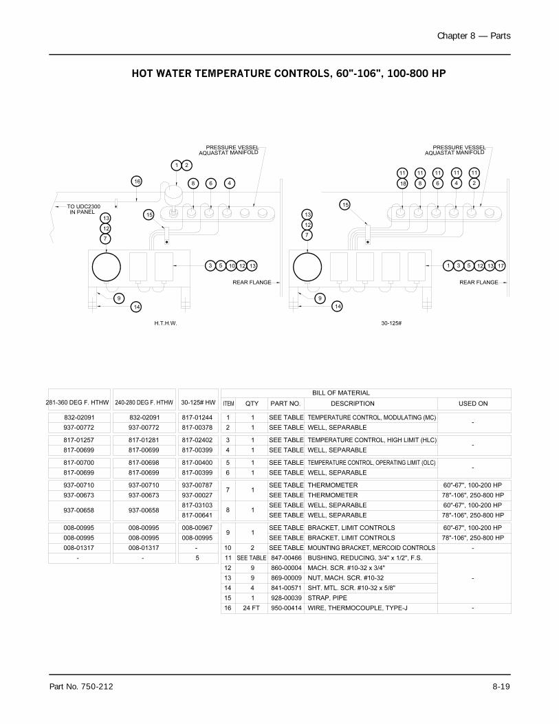
Chapter 8 — Parts
Part No. 750-212 8-19
11
4
11
8
REAR FLANGE
1312531
13
12
7
9
14
30-125#
15
DESCRIPTION
TEMPERATURE CONTROL, MODULATING (MC)
BILL OF MATERIAL
ITEM PART NO.
2
1
QTY
WELL, SEPARABLE
1
1
SEE TABLE
SEE TABLE
USED ON
TEMPERATURE CONTROL, HIGH LIMIT (HLC)SEE TABLE
SEE TABLE4 1
3 1
WELL, SEPARABLE
TEMPERATURE CONTROL, OPERATING LIMIT (OLC)
SEE TABLE
SEE TABLE
6 1
5 1
WELL, SEPARABLE
THERMOMETERSEE TABLE7 1
78"-106", 250-800 HP
60"-67", 100-200 HP
SEE TABLE THERMOMETER
SEE TABLE
SEE TABLE8 1
WELL, SEPARABLE
WELL, SEPARABLE
30-125# HW
937-00772
832-02091
240-280 DEG F. HTHW
817-00378
817-01244
281-360 DEG F. HTHW
832-02091
937-00772
817-00699 817-00399
817-02402817-01281
817-00699
817-01257
817-00698817-00700
817-00699 817-00699 817-00399
817-00400
937-00710
937-00673
937-00710
937-00673 937-00027
937-00787
937-00658817-00641
817-03103937-00658
SEE TABLE BRACKET, LIMIT CONTROLS
SEE TABLE9 1
008-00995008-00995
008-00995 008-00995
008-00967
008-00995 BRACKET, LIMIT CONTROLS
-
-
-
-
-
MACH. SCR. #10-32 x 3/4"
NUT, MACH. SCR. #10-32
SHT. MTL. SCR. #10-32 x 5/8"
MOUNTING BRACKET, MERCOID CONTROLS
BUSHING, REDUCING, 3/4" x 1/2", F.S.
841-00571
928-0003915
14
1
4
STRAP, PIPE
SEE TABLE
847-00466
860-00004
869-00009
12
13
11
9
9
10 2
-
008-01317
-
008-01317
5
-
6
11
2
11
AQUASTAT MANIFOLDPRESSURE VESSEL
H.T.H.W.
7
13
12
9
14
3
15
REAR FLANGE
125 10 13
8 6 4
1 2
16
IN PANELTO UDC2300
16 24 FT 950-00414 WIRE, THERMOCOUPLE, TYPE-J -
SEE TABLE
18
11
17
60"-67", 100-200 HP
60"-67", 100-200 HP
78"-106", 250-800 HP
78"-106", 250-800 HP
AQUASTAT MANIFOLDPRESSURE VESSEL
HOT WATER TEMPERATURE CONTROLS, 60"-106", 100-800 HP
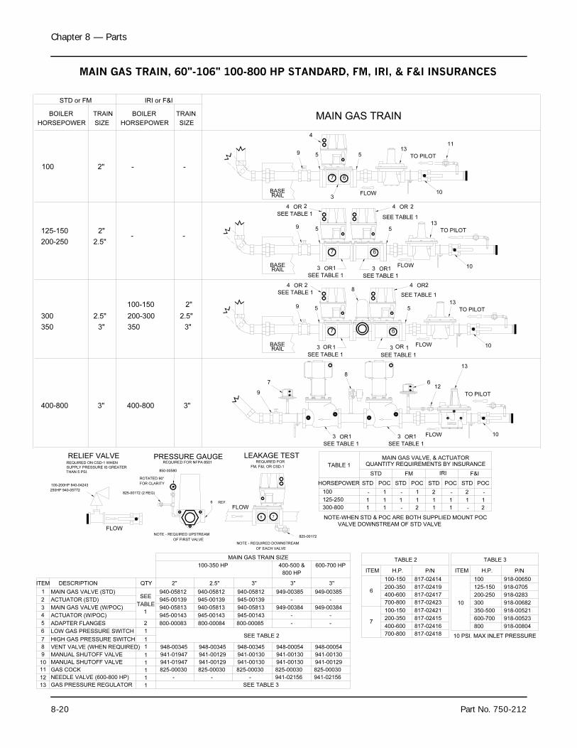
Chapter 8 — Parts
8-20 Part No. 750-212
LEAKAGE TEST
825-00172
5
3
7 6
67
67
8
4
REQUIRED FOR NFPA 8501
825-00172 (2 REQ)
850-00580
ROTATED 90°
FOR CLARITY
59
55
55
MAIN GAS TRAINBOILER
100
125-150
200-250
HORSEPOWER
TRAIN
SIZE
2"
2.5"
2"
BOILER
HORSEPOWER
TRAIN
-
- -
-
STD or FM IRI or F&I
SIZE
941-00129
948-00345
800-00084
2.5"
ADAPTER FLANGES
ACTUATOR (W/POC)
MAIN GAS VALVE (W/POC)
ACTUATOR (STD)
MAIN GAS VALVE (STD)
DESCRIPTION
9
8
7
5
MANUAL SHUTOFF VALVE
VENT VALVE (WHEN REQUIRED)
HIGH GAS PRESSURE SWITCH
ITEM
1
3
4
2
941-01947
948-00345
800-00083
2"
948-00345
941-00130
800-00085
MAIN GAS TRAIN SIZE
3"
9
9
QTY
SEE
TABLE
1945-00143
940-05813
945-00139
940-05812
2
6 LOW GAS PRESSURE SWITCHSEE TABLE 2
1
1
1
1
IRI
HORSEPOWER
100
125-250
300-800
STDPOC STD STD
FMSTD F&I
POC POC POCSTD
TABLE 1 QUANTITY REQUIREMENTS BY INSURANCE
- 1 - 1 2 - 2 -
1 1 1 1 1 1 1 1
1 1 - 2 1 1 - 2
H.P.
TABLE 2
200-350
100-150
P/NITEM
6
817-02414
817-02419
817-02415200-350
100-150 817-02421
7
100-200HP 940-04243
6 7
PRESSURE GAUGERELIEF VALVE
250HP 940-05772
REQUIRED FOR
FM, F&I, OR CSD-1
NOTE - REQUIRED DOWNSTREAM
OF EACH VALVE
6 REF.
NOTE - REQUIRED UPSTREAM
OF FIRST VALVE
SEE TABLE 1
REQUIRED ON CSD-1 WHEN
SUPPLY PRESSURE IS GREATER
THAN 5 PSI.
NOTE-WHEN STD & POC ARE BOTH SUPPLIED MOUNT POC
VALVE DOWNSTREAM OF STD VALVE
BASERAIL
RAILBASE
BASERAIL
FLOW
FLOW
940-05812
940-05813
945-00139
945-00143
940-05812
940-05813
945-00139
945-00143
MAIN GAS VALVE, & ACTUATOR
2OR4
SEE TABLE 1
1OR3
SEE TABLE 1
1OR3
SEE TABLE 1
2OR4
SEE TABLE 1
2OR4
SEE TABLE 1
24 OR
SEE TABLE 1
1OR3
SEE TABLE 1
1OR3
TO PILOT
FLOW 10
13
TO PILOT
10FLOW
13
TO PILOT
10FLOW
13
2.5"
3"350
300
3"
2.5"
350
200-300
2"100-150
13 GAS PRESSURE REGULATOR 1 SEE TABLE 3
918-0705125-150
200-250
350-500
30010
918-0283
918-00682
918-00521
TABLE 3
100
ITEM H.P. P/N
918-00650
11
825-000301GAS COCK11 825-00030 825-00030
TO PILOT
10
13
12
8
9
7 6
SEE TABLE 1
1OR3
SEE TABLE 1
3 OR1 FLOW
400-800 3" 400-800 3"
100-350 HP 400-500 &
3"
825-00030
948-00054
941-00130
949-00384
949-00385
-
-
-
400-600 817-02417
700-800 817-02423
400-600
700-800
817-02416
817-02418
600-700 918-00523
800 918-00804
-NEEDLE VALVE (600-800 HP)12 -1 941-02156-
10 MANUAL SHUTOFF VALVE 1 941-01947 941-00129 941-00130 941-00130
800 HP
941-02156
825-00030
600-700 HP
941-00130
949-00385
949-00384
948-00054
941-00129
-
-
-
3"
10 PSI. MAX INLET PRESSURE
MAIN GAS TRAIN, 60"-106" 100-800 HP STANDARD, FM, IRI, & F&I INSURANCES
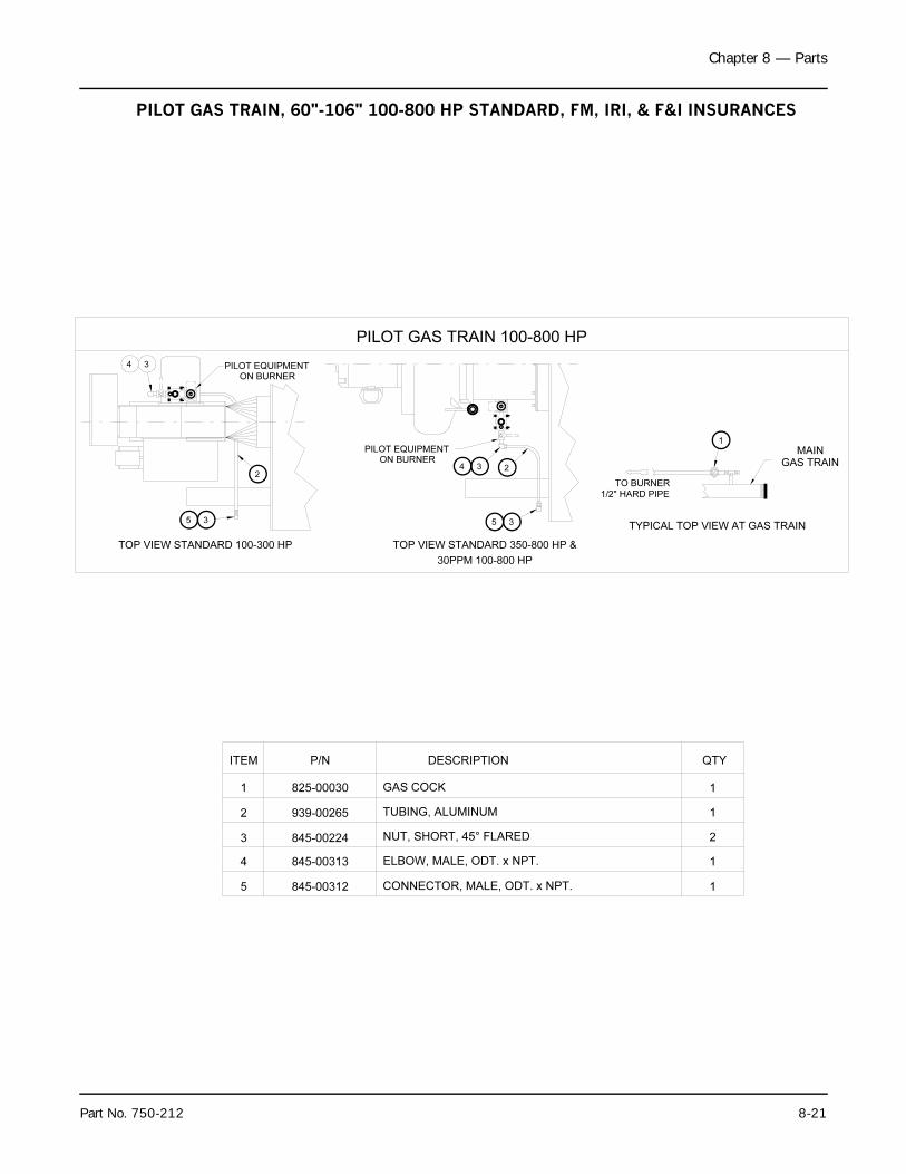
Chapter 8 — Parts
Part No. 750-212 8-21
CONNECTOR, MALE, ODT. x NPT.
ELBOW, MALE, ODT. x NPT.
NUT, SHORT, 45° FLARED
TUBING, ALUMINUM
GAS COCK
DESCRIPTION
5
ITEM
1
3
4
2
QTY
1
TOP VIEW STANDARD 100-300 HP
4 3
PILOT EQUIPMENT
PILOT GAS TRAIN 100-800 HP
5 3
2
ON BURNER
PILOT EQUIPMENT
ON BURNER
TOP VIEW STANDARD 350-800 HP &
5
4 3
3
2GAS TRAIN
TYPICAL TOP VIEW AT GAS TRAIN
TO BURNER
1/2" HARD PIPE
1
MAIN
30PPM 100-800 HP
1
2
1
1
845-00312
845-00224
845-00313
939-00265
825-00030
P/N
PILOT GAS TRAIN, 60"-106" 100-800 HP STANDARD, FM, IRI, & F&I INSURANCES

Chapter 8 — Parts
8-22 Part No. 750-212
COUPLING, HALF
VALVE, HORIZONTAL LIFT CHECK
BUSHING, RED. 1" X 1/2"
COMPRESSOR ASSY 182T/184T
PART NO. DESCRIPTIONQTY
ITEM
1 1 615-23
6 847-561
940-247017
12
11ITEM
894-3430200-208V (60 HZ)
894-3432
100-150HP
1 819-00158
600V (60 HZ)894-2788
200-208V (60 HZ)894-3661
SIDE ELEVATION
7
1
6
12 11
1/2"
1
60"78"
1/8"
Atomizing Air
Manifold Port Plug Manifold Port Plug
Manifold Block
Burner Back Cap(Shown For Ref. Only)
Proving Switch
Atomizing Air
Plug 1/2" NPT
Manifold Block Oil Pump
Proving Switch
Pressure Port(Plugged)Plug 1/2" NPT(Optional Low Oil Press. Sw.)
1/2" AIR PIPING, BY CUSTOMERROUTING FOR HEAVY OIL
ROUTING FOR LIGHT OIL
OIL RETURN CONNECTION (3/8" NPT.)
OIL SUPPLY CONNECTION (1/2" NPT.)
AIR SUPPLY CONN.
(1/2" NPT.)
HEAVY OIL INLET
FROM SIDE BURNER PIPING,
HEAVY OIL CUSTOMER FIELD
CONNECTIONS ON OIL HEATER.
FRONT ELEVATION
AIR SUPPLY CONN.
(1/2" NPT.)
1/2" UNION
230/460V (60 HZ)894-3662
230/460V (60 HZ)894-3653
600V (60 HZ)
200-300HP
AIR OIL PIPING 60”-78” 100-300HP
MOTOR, 2 HP , 1200 SRPM, 11
1 SEE TABLE 60"
MOTOR, 3 HP , 1800 SRPMSEE TABLE1 78"
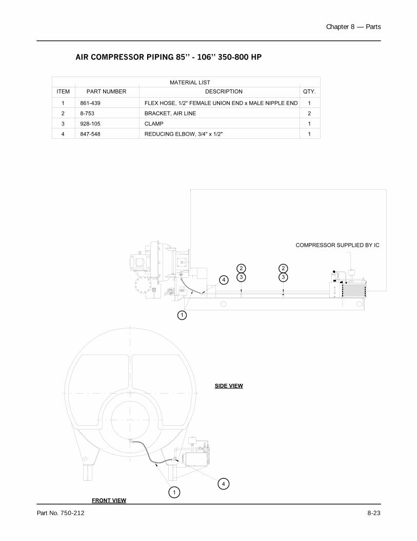
Chapter 8 — Parts
Part No. 750-212 8-23
3
2
4
1
COMPRESSOR SUPPLIED BY IC
SIDE VIEW
FRONT VIEW
1
4
MATERIAL LIST
ITEM PART NUMBER DESCRIPTION QTY.
1 861-439 FLEX HOSE, 1/2" FEMALE UNION END x MALE NIPPLE END 1
8-7532 BRACKET, AIR LINE 2
928-1053 CLAMP 1
847-5484 REDUCING ELBOW, 3/4" x 1/2" 1
2
3
AIR COMPRESSOR PIPING 85” - 106” 350-800 HP
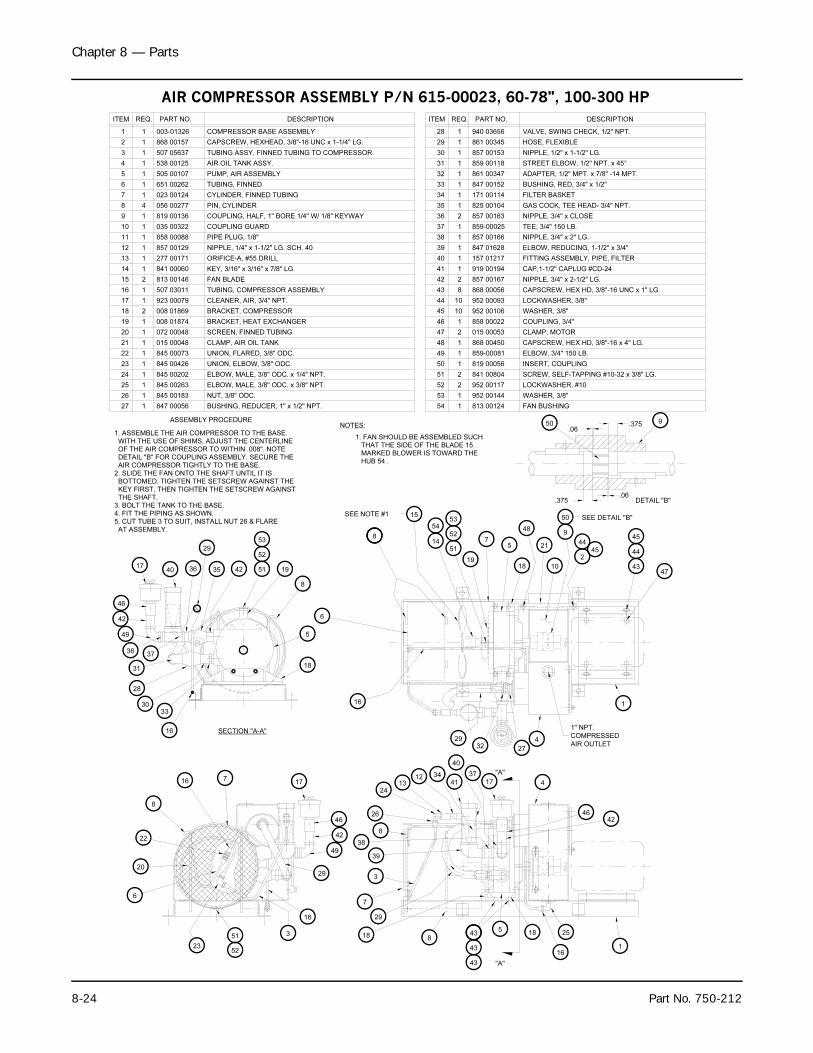
Chapter 8 — Parts
8-24 Part No. 750-212
ITEM
1
PART NO. DESCRIPTIONREQ.
1 003-01326 COMPRESSOR BASE ASSEMBLY
2
TUBING ASSY, FINNED TUBING TO COMPRESSOR507 0563713
4 538 001251 AIR OIL TANK ASSY.
CYLINDER, FINNED TUBING
PIN, CYLINDER
505 00107
651 00262
023 00124
056 0027748
7
6
1
1
5 1
TUBING, FINNED
PUMP, AIR ASSEMBLY
TUBING, COMPRESSOR ASSEMBLY
FAN BLADE
PIPE PLUG, 1/8"
NIPPLE, 1/4" x 1-1/2" LG. SCH. 40
KEY, 3/16" x 3/16" x 7/8" LG.114 841 00060
507 03011
813 00146
16 1
15 2
277 00171
819 00136
035 00322
858 00088
857 00129112
13 1
11
10
1
1
9 1
ORIFICE-A, #55 DRILL
COUPLING GUARD
COUPLING, HALF, 1" BORE 1/4" W/ 1/8" KEYWAY
SCREEN, FINNED TUBING
BRACKET, HEAT EXCHANGER
UNION, ELBOW, 3/8" ODC.
ELBOW, MALE, 3/8" ODC. x 1/4" NPT.
BUSHING, REDUCER, 1" x 1/2" NPT.
845 00202
845 00263
845 00183
847 0005627
26
1
1
25
24
1
1
ELBOW, MALE, 3/8" ODC. x 3/8" NPT.
NUT, 3/8" ODC.
072 00048
008 01874
008 01869
923 00079
845 00426
845 00073
23
22
1
1
21
20 1
117
19
18
1
2
UNION, FLARED, 3/8" ODC.
CLEANER, AIR, 3/4" NPT.
BRACKET, COMPRESSOR
CLAMP, AIR OIL TANK015 000481
868 001571 CAPSCREW, HEXHEAD, 3/8"-16 UNC x 1-1/4" LG.
50 9
"A"
"A"
SECTION "A-A"
36
36 35 42
3330
28
31
29 51
19
52
53
14
54
15
6
8
51 19
8
5
18
16
SEE NOTE #1
6
20
22
16
8
16
3
23
51
52
29
7
52
535
7
18
48
21
9
50 SEE DETAIL "B"
2
44
45
43
44
47
45
1
1" NPT.
COMPRESSED
AIR OUTLET2732
29
10
16
4
3
26
2413
12 34
41
40
39
38
8
37
42
17
46
7
1
25
16
18 43
43
43
185
4
29
8
DETAIL "B"
ASSEMBLY PROCEDURE
1. ASSEMBLE THE AIR COMPRESSOR TO THE BASE.
WITH THE USE OF SHIMS, ADJUST THE CENTERLINE
OF THE AIR COMPRESSOR TO WITHIN .008". NOTE
DETAIL "B" FOR COUPLING ASSEMBLY. SECURE THE
AIR COMPRESSOR TIGHTLY TO THE BASE.
2. SLIDE THE FAN ONTO THE SHAFT UNTIL IT IS
BOTTOMED. TIGHTEN THE SETSCREW AGAINST THE
KEY FIRST, THEN TIGHTEN THE SETSCREW AGAINST
THE SHAFT.
3. BOLT THE TANK TO THE BASE.
4. FIT THE PIPING AS SHOWN.
5. CUT TUBE 3 TO SUIT, INSTALL NUT 26 & FLARE
AT ASSEMBLY.
NOTES:
1. FAN SHOULD BE ASSEMBLED SUCH
THAT THE SIDE OF THE BLADE 15
MARKED BLOWER IS TOWARD THE
HUB 54 .
17
46
42
49
17
49
42
46
40
37
1 868 0045048 CAPSCREW, HEX HD, 3/8"-16 x 4" LG.
ELBOW, 3/4" 150 LB.
SCREW, SELF-TAPPING #10-32 x 3/8" LG.
819 00056
859-00081
952 00117
952 00144
813 00124
841 00804
54 1
251
52
53
2
1
50
49
1
1
FAN BUSHING
INSERT, COUPLING
WASHER, 3/8"
LOCKWASHER, #10
ADAPTER, 1/2" MPT. x 7/8" -14 MPT.
STREET ELBOW, 1/2" NPT. x 45°
VALVE, SWING CHECK, 1/2" NPT.
NIPPLE, 1/2" x 1-1/2" LG.
NIPPLE, 3/4" x 2" LG.
NIPPLE, 3/4" x CLOSE
NIPPLE, 3/4" x 2-1/2" LG.
CAPSCREW, HEX HD, 3/8"-16 UNC x 1" LG.
CAP,1-1/2" CAPLUG #CD-24
FITTING ASSEMBLY, PIPE, FILTER
ELBOW, REDUCING, 1-1/2" x 3/4"
GAS COCK, TEE HEAD- 3/4" NPT.
BUSHING, RED, 3/4" x 1/2"
1 859-00025 TEE, 3/4" 150 LB.37
858 00022
015 00053
857 00166
857 00167
868 00056
157 01217
919 00194
847 01628
952 00106
952 00093
46
47 2
1
44
45
43
10
10
8
42
40
41 1
2
1
39
38
1
1
CLAMP, MOTOR
COUPLING, 3/4"
WASHER, 3/8"
LOCKWASHER, 3/8"
861 00347
861 00345
940 03656
859 00118
857 00153
825 00104
857 00163
171 00114
847 00152
134
36
35
2
1
32
33 1
1
31
30
29
1
1
1
28 1
FILTER BASKET
HOSE, FLEXIBLE
DESCRIPTIONREQ.ITEM PART NO.
.06.375
.06.375
AIR COMPRESSOR ASSEMBLY P/N 615-00023, 60-78", 100-300 HP
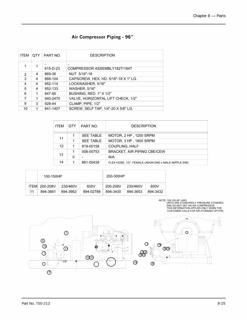
Chapter 8 — Parts
Part No. 750-212 8-25
COUPLING, HALF
MOTOR, 2 HP , 1200 SRPM
PART NO. DESCRIPTIONQTYITEM
111 SEE TABLE
12
11
ITEM
894-3430
200-208V
894-3432
600V
1 819-00158
600V
894-02788
200-208V
894-3661
MOTOR, 3 HP , 1800 SRPMSEE TABLE1
131 008-00753 BRACKET, AIR PIPING CBE/CEW
1
2345
8
CAPSCREW, HEX. HD. 5/16"-18 X 1" LG.
VALVE, HORIZONTAL LIFT CHECK, 1/2"
SCREW, SELF TAP, 1/4"-20 X 5/8" LG.10
9
7
3
1
1
841-1407
928-44
940-2470
CLAMP, PIPE, 1/2"
2
6
5
4
3
1
4
4
4
1
ITEM
4
1
QTY
847-56
952-133
952-114
868-104
869-36
-
PART NO. DESCRIPTION
COMPRESSOR ASSEMBLY182T/184T
LOCKWASHER, 5/16"
BUSHING, RED. 1" X 1/2"
NUT 5/16"-18
WASHER, 5/16"
FLEX HOSE, 1/2", FEMALE UNION END x MALE NIPPLE END861-00439114
N/A-0
16
230/460V
894-3662
230/460V
894-3653
615-D-23-
100-150HP 200-300HP
NOTE: 100-150 HP. 4WG
UNITS ARE STANDARDLY PRESSURE ATOMIZED
AND DO NOT GET AN AIR COMPRESSOR.
THIS INFORMATION APPLIES ONLY WHEN THE
CUSTOMER CALLS FOR AIR ATOMIZED OPTION.
9 10
16
910
1/8"
8
7
12
6
11
1
Air Compressor Piping - 96”
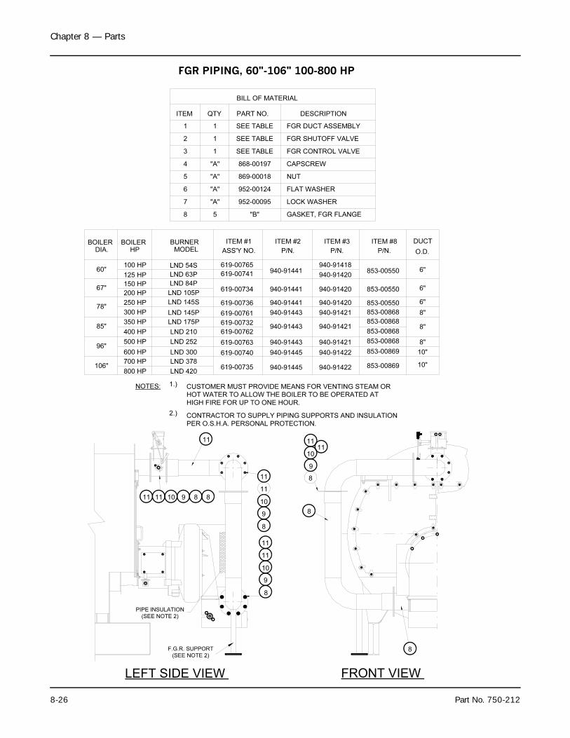
Chapter 8 — Parts
8-26 Part No. 750-212
NOTES: 1.) CUSTOMER MUST PROVIDE MEANS FOR VENTING STEAM OR
HOT WATER TO ALLOW THE BOILER TO BE OPERATED AT
HIGH FIRE FOR UP TO ONE HOUR.
2.) CONTRACTOR TO SUPPLY PIPING SUPPORTS AND INSULATION
PER O.S.H.A. PERSONAL PROTECTION.
8
11
F.G.R. SUPPORT
(SEE NOTE 2)
LEFT SIDE VIEW
(SEE NOTE 2)
PIPE INSULATION
FRONT VIEW
9
8
10
9
8
10
8
8
11
1011 889
10
9
11
11
11
11
11
11
DIA.BOILER BOILER
HPBURNER
MODEL ASS'Y NO.
ITEM #1
868-00197
869-00018
952-00095
952-00124
PART NO.
5 "B"
"A"
"A"
"A"
"A"
8
5
6
7
QTY
2
3
4
ITEM
1
1
1
1 SEE TABLE
GASKET, FGR FLANGE
CAPSCREW
FGR DUCT ASSEMBLY
DESCRIPTION
LOCK WASHER
FLAT WASHER
NUT
FGR CONTROL VALVE
FGR SHUTOFF VALVE
O.D.
DUCT
100 HP60"
LND 63P 619-007416"853-00550
350 HP85"
LND 175P 619-00732 853-00868
250 HP78"
LND 145S 619-00736 6"853-00550
700 HP106"
LND 378619-00735 10"853-00869
500 HP96"
LND 252 619-00763
10"853-00869
67"150 HP
LND 105P619-00734 6"853-00550
600 HP
800 HP
300 HP
200 HP
125 HP
400 HP
LND 420
LND 300
LND 210
LND 145P 619-00761
619-00740
619-00762
8"
8"
8"
853-00868
853-00868
853-00868
LND 84P
LND 54S 619-00765
SEE TABLE
SEE TABLE
ITEM #2
P/N.
940-91441940-91418
ITEM #3
P/N. P/N.
ITEM #8
BILL OF MATERIAL
940-91441
940-91441
940-91443
940-91443
940-91443
940-91445
940-91445
940-91420
940-91420
940-91420
940-91421
940-91421
940-91421
940-91422
940-91422
FGR PIPING, 60"-106" 100-800 HP
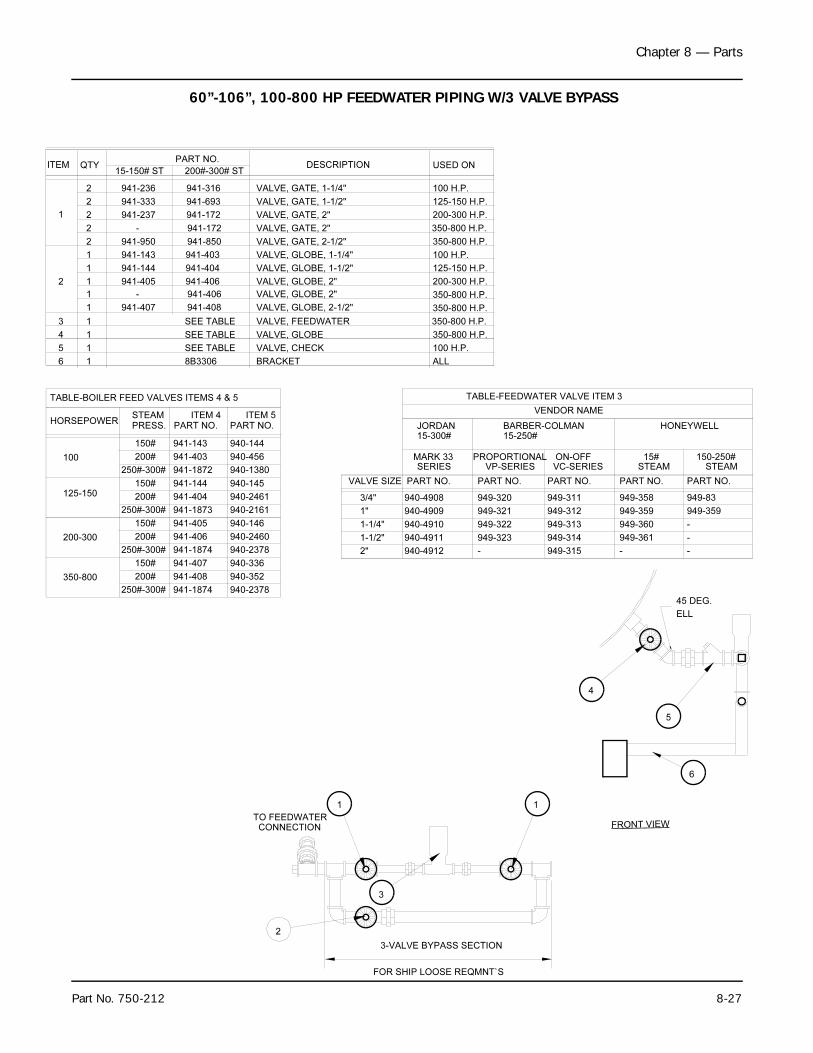
Chapter 8 — Parts
Part No. 750-212 8-27
VALVE, CHECK
VALVE, GLOBE
VALVE, FEEDWATER
VALVE, GLOBE, 2-1/2"
VALVE, GLOBE, 2"
VALVE, GLOBE, 1-1/2"
VALVE, GLOBE, 1-1/4"
VALVE, GATE, 2-1/2"
VALVE, GATE, 2"
VALVE, GATE, 1-1/2"
VALVE, GATE, 1-1/4"
PART NO.USED ONDESCRIPTIONQTYITEM
2 941-236 100 H.P.
2 941-333 125-150 H.P.
941-23721
350-800 H.P.941-9502
100 H.P.941-1431
125-150 H.P.941-1441
200-300 H.P.941-40512
350-800 H.P.941-4071
SEE TABLE13
SEE TABLE1
SEE TABLE1
4
5
941-408
941-406
941-404
941-403
941-850
941-172
941-693
941-316
2"
1-1/2"
1-1/4"
1"
3/4"
940-4912
940-4911
940-4910
940-4909
940-4908
VALVE SIZE PART NO.
SERIESMARK 33
JORDAN BARBER-COLMAN
PROPORTIONAL VP-SERIES
PART NO.
949-320
949-321
949-322
949-323
-
ON-OFF VC-SERIES
PART NO.
949-311
949-312
949-313
949-314
949-315
HONEYWELL
15# STEAM
PART NO.
949-358
949-359
949-360
949-361
-
150-250# STEAM
PART NO.
949-83
949-359
-
-
-
VENDOR NAME
TABLE-FEEDWATER VALVE ITEM 3
350-800
200-300
125-150
100
200#
150#
200#
150#
200#
150#
200#
150#
941-408
941-407
941-406
941-405
941-404
941-144
941-403
941-143
940-352
940-336
940-2460
940-146
940-2461
940-145
940-456
940-144
PRESS. PART NO. PART NO.HORSEPOWER
STEAM ITEM 4
TABLE-BOILER FEED VALVES ITEMS 4 & 5
TO FEEDWATERCONNECTION FRONT VIEW
15-150# ST 200#-300# ST
250#-300# 941-1872 940-1380
941-1873 940-2161
941-1874 940-2378
941-1874 940-2378
350-800 H.P.2 - VALVE, GATE, 2"
1 - VALVE, GLOBE, 2" 350-800 H.P.
200-300 H.P.
941-406
941-172
ITEM 5
100 H.P.
350-800 H.P.
350-800 H.P.
2
3-VALVE BYPASS SECTION
FOR SHIP LOOSE REQMNT`S
1
6
5
4
1
3
45 DEG.
ELL
8B33066 1 BRACKET ALL
15-300# 15-250#
250#-300#
250#-300#
250#-300#
60”-106”, 100-800 HP FEEDWATER PIPING W/3 VALVE BYPASS
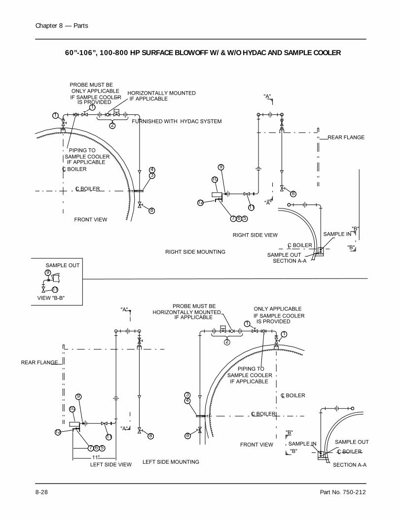
Chapter 8 — Parts
8-28 Part No. 750-212
2
PROBE MUST BE
1
C BOILERL
LC BOILER
11
9
10
812
7 6 5FRONT VIEW
LEFT SIDE VIEW
"A"
REAR FLANGE
9
11
SAMPLE OUT
VIEW "B-B"
"B"
C BOILERL
SAMPLE IN
SAMPLE OUT
PIPING TO
12
RIGHT SIDE VIEW
567
11
8
10
REAR FLANGE
9
"A"
"A"
C BOILERL
FRONT VIEW
8
34
2FURNISHED WITH HYDAC SYSTEM
1
LC BOILER
LEFT SIDE MOUNTING
RIGHT SIDE MOUNTING"B"
SECTION A-A
SAMPLE IN
C BOILER
SAMPLE OUT
L
SECTION A-A
"B"
"B"
HORIZONTALLY MOUNTEDIF APPLICABLE
SAMPLE COOLER
IF APPLICABLE
"A"
11"
IF APPLICABLESAMPLE COOLER
PIPING TO
HORIZONTALLY MOUNTED
PROBE MUST BE
IF APPLICABLE
43
8
1
1
ONLY APPLICABLE
IS PROVIDEDIF SAMPLE COOLER
ONLY APPLICABLE
IF SAMPLE COOLERIS PROVIDED
60”-106”, 100-800 HP SURFACE BLOWOFF W/ & W/O HYDAC AND SAMPLE COOLER
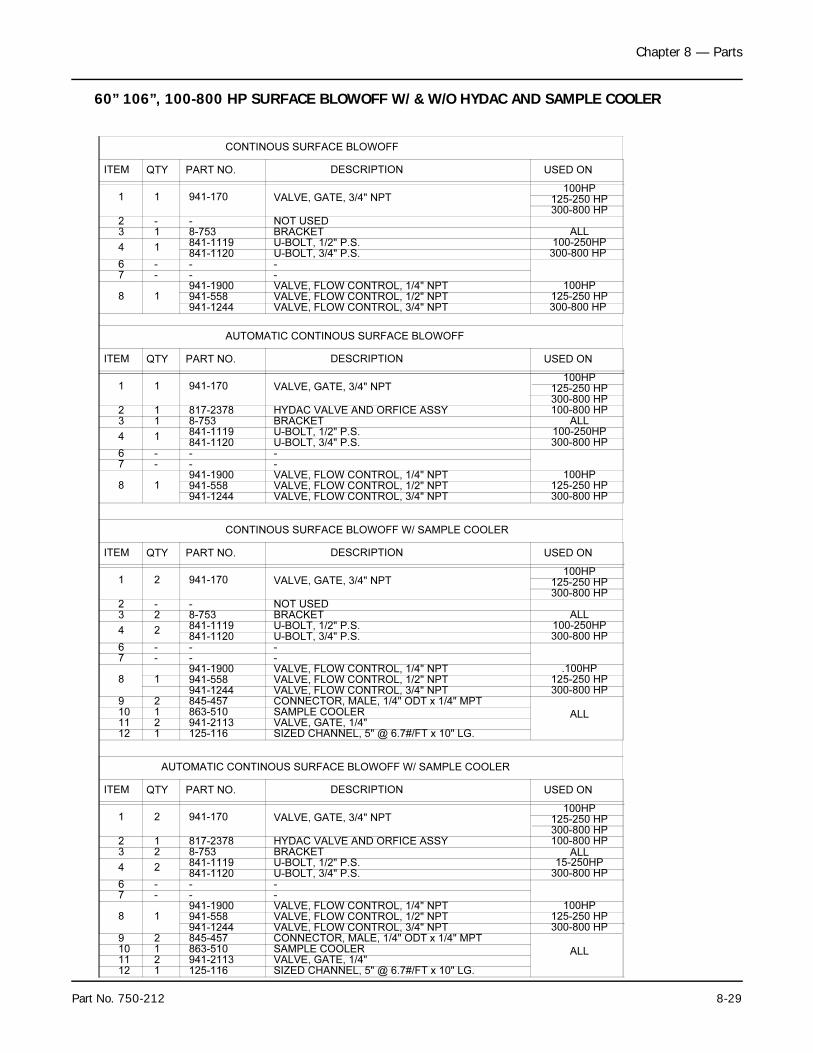
Chapter 8 — Parts
Part No. 750-212 8-29
VALVE, FLOW CONTROL, 1/4" NPT--
U-BOLT, 1/2" P.S.BRACKET
VALVE, GATE, 3/4" NPT
PART NO. DESCRIPTIONQTYITEM
1 1 941-170
8-75313841-111914
--6--7941-1900
18
HYDAC VALVE AND ORFICE ASSY 817-23782 1
CONTINOUS SURFACE BLOWOFF
USED ON
100HP125-250 HP300-800 HP
941-558941-1244
VALVE, FLOW CONTROL, 1/2" NPTVALVE, FLOW CONTROL, 3/4" NPT
125-250 HP100HP
ITEM QTY PART NO. DESCRIPTION USED ON
AUTOMATIC CONTINOUS SURFACE BLOWOFF
VALVE, GATE, 3/4" NPT1 1 941-170 125-250 HP100HP
VALVE, FLOW CONTROL, 3/4" NPT941-1244VALVE, FLOW CONTROL, 1/2" NPTVALVE, FLOW CONTROL, 1/4" NPT
8 1 941-558941-1900 100HP
125-250 HP
100-800 HP
VALVE, GATE, 3/4" NPT
VALVE, FLOW CONTROL, 1/2" NPTVALVE, FLOW CONTROL, 1/4" NPT
DESCRIPTION
CONTINOUS SURFACE BLOWOFF W/ SAMPLE COOLER
VALVE, FLOW CONTROL, 3/4" NPT941-12448 1
1 2
ITEM QTY
941-558941-1900
941-170
PART NO.
.100HP125-250 HP
125-250 HP100HP
USED ON
CONNECTOR, MALE, 1/4" ODT x 1/4" MPT
SIZED CHANNEL, 5" @ 6.7#/FT x 10" LG.VALVE, GATE, 1/4"SAMPLE COOLER
1211109
1212
863-510845-457
125-116941-2113
ALL
SIZED CHANNEL, 5" @ 6.7#/FT x 10" LG.VALVE, GATE, 1/4"SAMPLE COOLERCONNECTOR, MALE, 1/4" ODT x 1/4" MPTVALVE, FLOW CONTROL, 3/4" NPT
VALVE, FLOW CONTROL, 1/4" NPTVALVE, FLOW CONTROL, 1/2" NPT
1112
1021
19
8
2
1
125-116941-2113863-510
941-1900941-558941-1244845-457
ALL
125-250 HP100HP
AUTOMATIC CONTINOUS SURFACE BLOWOFF W/ SAMPLE COOLER
DESCRIPTION
VALVE, GATE, 3/4" NPT1 2
ITEM QTY
941-170
PART NO. USED ON
100HP125-250 HP
2 1 HYDAC VALVE AND ORFICE ASSY 817-2378
NOT USED2 - -
NOT USED2 - -
100-250HP841-1120 U-BOLT, 3/4" P.S.
U-BOLT, 3/4" P.S.U-BOLT, 1/2" P.S.
76
--
3
4
1
1841-1120
--
841-11198-753
--
BRACKET100-250HP
7
U-BOLT, 1/2" P.S.U-BOLT, 3/4" P.S.
6 --
--
--
4
3
2
2841-1119841-1120
8-753 BRACKET100-250HP
3 2 8-753 BRACKET
U-BOLT, 3/4" P.S.U-BOLT, 1/2" P.S.
76
--
4 2
--841-1120841-1119
--
15-250HP
ALL
300-800 HP
300-800 HP
300-800 HP
300-800 HP
300-800 HP
ALL
ALL
300-800 HP
300-800 HP
300-800 HP
100-800 HPALL
300-800 HP
300-800 HP
300-800 HP
60” 106”, 100-800 HP SURFACE BLOWOFF W/ & W/O HYDAC AND SAMPLE COOLER
Chapter 8 — Parts
8-30 Part No. 750-212
Notes:

NOTES