cleen consortium open session october 27, 2010 · cleen consortium open session october 27, ... •...
TRANSCRIPT

CLEEN ConsortiumOpen Session
October 27, 2010
P. M. Niskode’ Program ManagerRick Stickles TAPS II ManagerBarry Allmon Open Rotor ManagerRoss DeJong FMS/ATM Program Mgr
ecomaginationSM

2GE – Aviation
11/12/2010
GE CLEEN Technologies
1. Open Rotor
2. TAPS II Combustor
3. FMS/ATM Integration

3GE – Aviation
11/12/2010
FAA CLEEN Program Goals
Develop and demonstrate (TRL 6-7) certifiable aircraft technology

4GE – Aviation
11/12/2010
GE CLEEN Program GoalsTimeframe: CY 2010-2015
Open Rotor• 26% fuel burn reduction (relative to CFM56-7B)• 17 EPNdB noise reduction (relative to stage 4)
TAPS II Combustor• Emissions 60% below CAEP/6
FMS & ATM• 7% fuel burn/CO2 reduction• 22% landing noise reduction (area of 60 EPNdB footprint)

5GE – Aviation
11/12/2010
1. Open Rotor

6GE – Aviation
11/12/2010
GE Open Rotor Overview
Goal• 26% fuel burn reduction (relative to CFM56-7B)• 15 to 17 EPNdB noise reduction (relative to stage
4)
OR Program has two work elements:• Blade aero-acoustic assessment and • Pitch Change Mechanism (PCM) including control
system integration
7GE – Aviation
11/12/2010
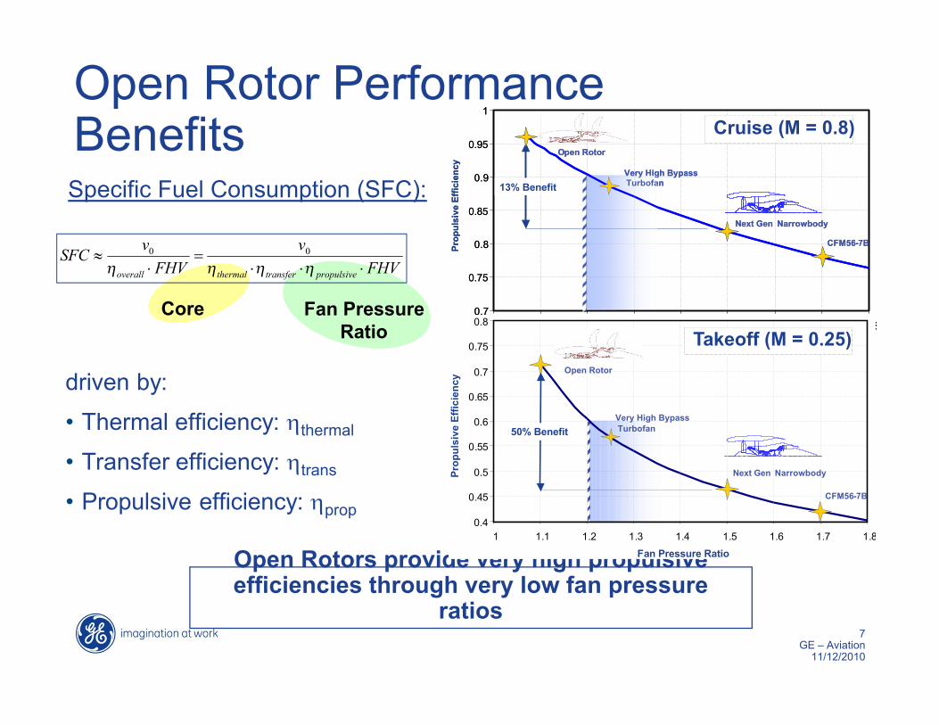
Open Rotor Performance Benefits
Open Rotors provide very high propulsive efficiencies through very low fan pressure
ratios
Core Fan PressureRatio
Specific Fuel Consumption (SFC):
FHVv
FHVvSFC
propulsivetransferthermaloverall
00
driven by:
• Thermal efficiency: thermal
• Transfer efficiency: trans
• Propulsive efficiency: prop
CFM56-7B
13% Benefit
Next Gen Narrowbody
Open Rotor
Very High BypassTurbofan
0.7
0.75
0.8
0.85
0.9
0.95
1
1 1.1 1.2 1.3 1.4 1.5 1.6 1.7 1.8
Prop
ulsi
ve E
ffici
ency
CFM56-7B
13% Benefit
Next Gen Narrowbody
Open Rotor
Very High BypassTurbofan
0.7
0.75
0.8
0.85
0.9
0.95
1
1 1.1 1.2 1.3 1.4 1.5 1.6 1.7 1.8
Prop
ulsi
ve E
ffici
ency
0.4
0.45
0.5
0.55
0.6
0.65
0.7
0.75
0.8
1 1.1 1.2 1.3 1.4 1.5 1.6 1.7 1.8
Fan Pressure Ratio
Prop
ulsi
ve E
ffici
ency
CFM56-7B
Next Gen Narrowbody
Open Rotor
Very High BypassTurbofan50% Benefit
Takeoff (M = 0.25)
Cruise (M = 0.8)

8GE – Aviation
11/12/2010
Thickness / steady loading noise
Forward Fan Tones Interaction Tones (+ BBN)
Thickness / steady loading noiseAft Fan Tones
Thickness / steady loading noise
Forward Fan Tones
Vortex / blade interactionInteraction Tones (+ BBN)
Pylon / Blade interactionForward Fan Tones
Thickness / steady loading noiseAft Fan Tones
Compressor Noise(Tones + BBN)
Turbine Noise(Tones + BBN)
Jet Noise(BBN)
Fan Wake interaction Interaction Tones (+ BBN)
IncidenceForward Fan Tones
IncidenceForward Fan Tones
Thickness / steady loading noise
Forward Fan Tones Interaction Tones (+ BBN)
Thickness / steady loading noiseAft Fan Tones
Thickness / steady loading noise
Forward Fan Tones
Vortex / blade interactionInteraction Tones (+ BBN)
Pylon / Blade interactionForward Fan Tones
Thickness / steady loading noiseAft Fan Tones
Compressor Noise(Tones + BBN)
Turbine Noise(Tones + BBN)
Jet Noise(BBN)
Fan Wake interaction Interaction Tones (+ BBN)
Fan Wake interaction Interaction Tones (+ BBN)
IncidenceForward Fan Tones
IncidenceForward Fan Tones
Open Rotor Noise Physics
Acoustic design features can reduce efficiency gains
Fan Sources
Other Sources
Tone-dominated noise signature• R1-R2 Interaction
– Wake – Vortex
• Pylon Wake Interaction• Incidence Angle
9GE – Aviation
11/12/2010
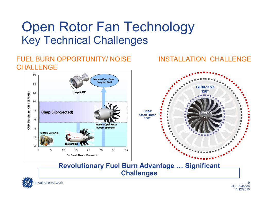
Open Rotor Fan TechnologyKey Technical Challenges
INSTALLATION CHALLENGE
Revolutionary Fuel Burn Advantage … Significant Challenges
MD-80 FTD
FUEL BURN OPPORTUNITY/ NOISE CHALLENGE
0
2
4
6
8
10
12
14
16
0 5 10 15 20 25 30 35
% Fu e l Bu r n Be n e fit
CU
M M
argi
n, re
: CH
4 (E
PNdB
)
Chap 5 (projected)
Modern Open Rotor Program Goal
GE36 (1980)
CFM56-5B (2010)
Leap-X ATF
Modern Open Rotor(current estimate)
0
2
4
6
8
10
12
14
16
0 5 10 15 20 25 30 35
% Fu e l Bu r n Be n e fit
CU
M M
argi
n, re
: CH
4 (E
PNdB
)
Chap 5 (projected)
Modern Open Rotor Program Goal
GE36 (1980)GE36 (1980)
CFM56-5B (2010)
Leap-X ATFLeap-X ATF
Modern Open Rotor(current estimate)Modern Open Rotor(current estimate)
GE90-115B128”
LEAPOpen Rotor
168”
LEAP-X~71”

10GE – Aviation
11/12/2010
Open Rotor Blades Program Plan
• Develop advanced technology blade designs • Refine designs thru aero-acoustics model tests • Project blade model data to full-scale application
OC
T
NO
V
DEC
JAN
FEB
MA
R
APR
MA
Y
JUN
JUL
AU
G
SEP
OC
T
NO
V
DEC
JAN
FEB
MA
R
APR
MA
Y
JUN
JUL
AU
G
SEP
OC
T
NO
V
DEC
Phase I (GE/NASA Collaboration)Low Speed Testing (NASA 9x15 LSWT)High Speed Testing (NASA 8x6 HSWT)Phase II (FAA CLEEN)Phase I Data Reduction/AnalysisPhase II DesignHardware FabricationTesting (NASA 8x6 HSWT, NASA 9x15 LSWT)Data Reduction/Analysis
TASK
201120102009
Phase II FAA CLEEN Effort Builds upon Phase I NASA/GE Effort

11GE – Aviation
11/12/2010
Open Rotor PCM System Definition
Selected Hydraulic System for Improved Reliability and Weight Savings
Technical Issues and Challenges• Transfer of fluid from stationary to rotating system
– Control system responses• Integration of PCM hydraulics into engine oil
system– Heat dissipation

12GE – Aviation
11/12/2010
Open Rotor PCM Program Plan
• Validation of hydraulic oil transfer mechanism thru a rig test
• Conduct Thermal Management Studies– Develop whole engine thermal model with flight profiles– Establish component requirements
Conceptual Studies & Down-select
2009 2010 2011
Design & Procure Rig
Assemble, Instrument & Test

2. GE TAPS II Combustor
14GE – Aviation
11/12/2010
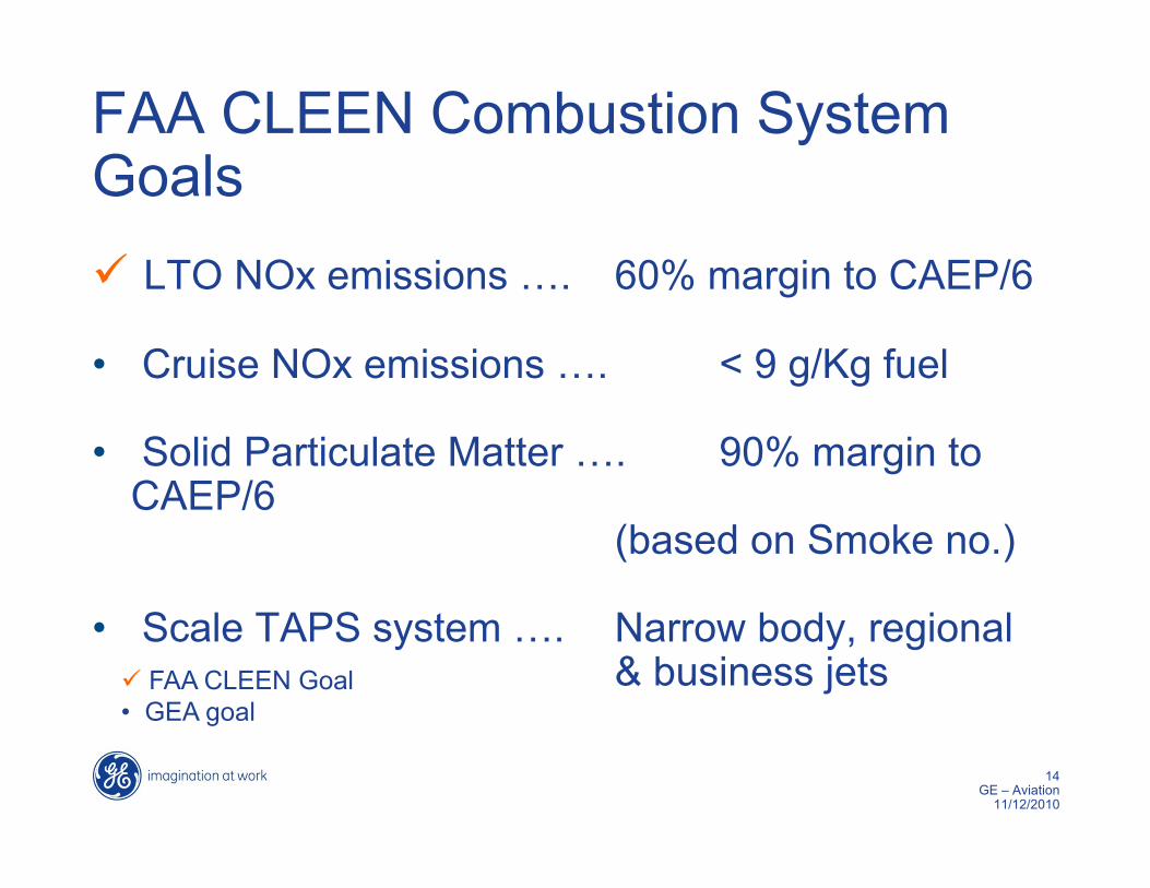
FAA CLEEN Combustion System Goals LTO NOx emissions …. 60% margin to CAEP/6
• Cruise NOx emissions …. < 9 g/Kg fuel
• Solid Particulate Matter …. 90% margin to CAEP/6
(based on Smoke no.)
• Scale TAPS system …. Narrow body, regional & business jets FAA CLEEN Goal
• GEA goal

15GE – Aviation
11/12/2010
GE Aviation Approach:TAPS (Twin annular Premixing Swirler)
Twin annular flames• Staged combustion within mixer• Lean-premixed fuel/air mixture in
main swirler for reduced NOx at high power
• Central pilot for good operability and low CO/HC at low power
• Greater NOx Reduction at Cruise
FADEC sets optimum fuel splits• Balance Emissions, Operability
Durability, and Dynamics
Premixing flame zone
Pilot flame zone
Air
Fuel injection
Cyclone mixer
Pilot
Nozzle sprays shown without air flow(or cyclone mixer)
Pilot Only Pilot + Main
16GE – Aviation
11/12/2010
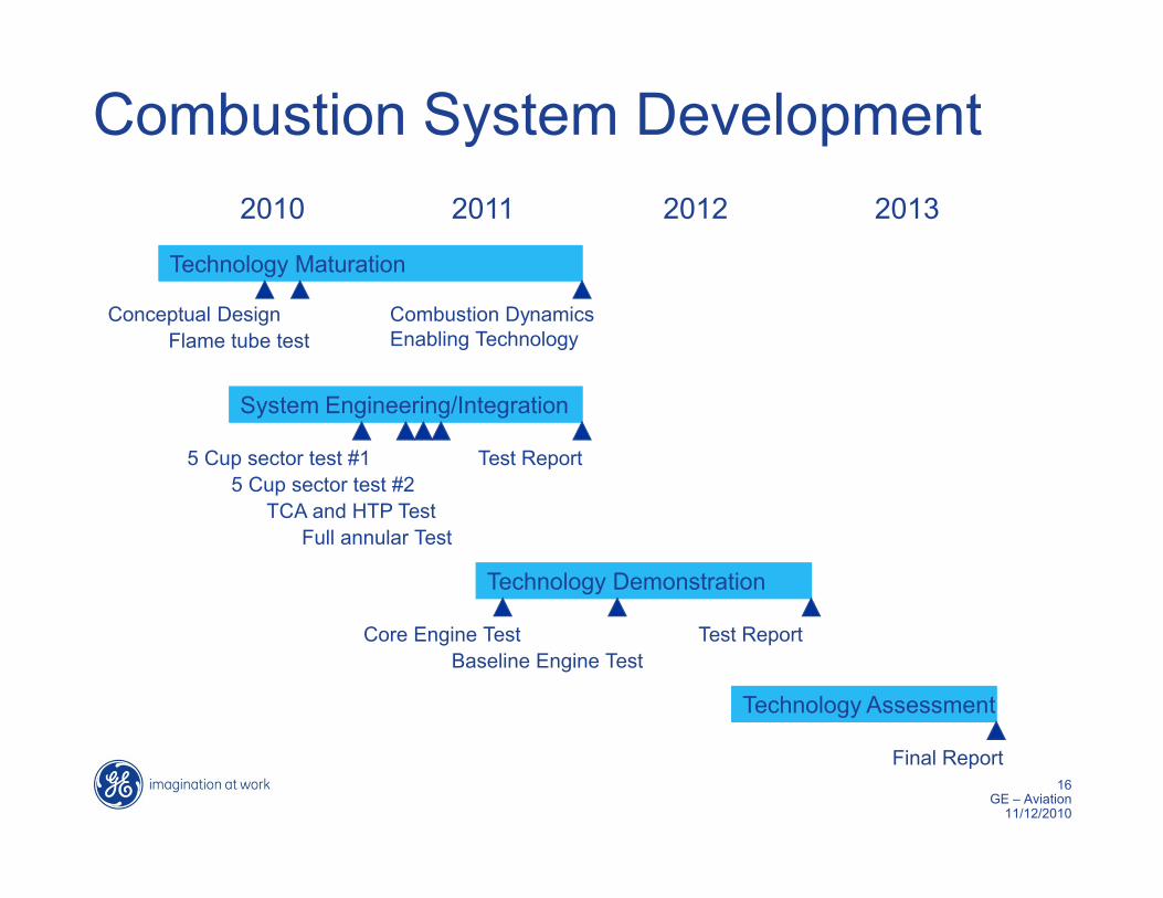
Combustion System Development2010 2011 2012 2013
Technology Maturation
System Engineering/Integration
Technology Demonstration
Technology Assessment
Conceptual DesignFlame tube test
Combustion Dynamics Enabling Technology
5 Cup sector test #1
TCA and HTP Test5 Cup sector test #2
Full annular Test
Test Report
Core Engine TestBaseline Engine Test
Test Report
Final Report

3. FMS/ATM Integration

18GE – Aviation
11/12/2010
FMS/ATM Overview
4D Trajectory NegotiationIntegrated with ATM to fly the most fuel-efficient profile, avoiding fuel-consuming and noisy low-level vectors, improving overall airspace efficiency
Trajectory OptimizationImproved efficiency throughout the flight - from takeoff to landing - for fuel and emissions savings
4D Trajectory SynchronizationCommon view of optimized trajectory to improve predictability and facilitate efficient negotiation
Optimized Profile DescentEliminates increased throttle use to reduce noise, fuel consumption and emissions, reducing noise footprint

19GE – Aviation
11/12/2010
FMS/ATM OverviewGoals• Optimize the 4-D trajectory flown by the aircraft throughout flight• Implement GE’s FMS technologies to optimize take-off, cruise and
landing• Synchronize trajectories in airborne FMS and Lockheed Martin’s
ERAM• Utilize AirDat’s accurate real time weather to reduce fuel consumption• Demonstrate technologies with Alaska Airlines
Key Activities• Collect baseline data to quantify fuel burn, noise and emissions• Mature FMS & FMS/ATM technologies• Determine optimum use of weather• Develop simulation environment to emulate broad range of scenarios• Demonstrate technology & validate simulation in 737 shadow-mode
trials

20GE – Aviation
11/12/2010
FMS/ATM Program Plan

21GE – Aviation
11/12/2010
Challenges & Technical IssuesTechnology Maturation
• Reaching TRL 6-7 requires significant coordination with FAA• AEE, ATO-P, ATO-E and Flight Standards
Simulation Environment• Creation of real time FMS-ERAM simulation environment • Necessary to model and quantify fuel savings• Accommodate multiple scenarios & technologies
Weather Benefits• Numerous weather options and variants of data to analyze
Flight Demonstration• FMS/ERAM will require shadow mode of live ATC• Requires considerable planning and FAA coordination

Future Symposium Topics
• Plan/process to feed CLEEN progress back into standardization committees – e.g. RTCA SC-214 4D trajectory downlink

23GE – Aviation
11/12/2010