climb and descent management · climb and descent management version 1.1 6 february 2016 ... the...
TRANSCRIPT
Climb and descent management Version 1.1 6 February 2016 Page 1
© IVAO HQ training department Training Documentation Manager Erwan L’hotellier
This manual is dedicated only for IVAOTM Network activities. This document must not be used in real aviation or in other networks
CLIMB AND DESCENT MANAGEMENT
1. Introduction
In a terminal area or inside an area controller’s airspace, the descent or climb management can be difficult
to handle since the controller shall ensure enough safety all the time in order to create optimal regulation
flows, and to satisfy pilot requests at the same time.
This management shall be performed handling several types of aircraft with different capabilities inside the
same airspace.
2. Minimum separation
This is a reminder of the applicable minimum separation. To get more details, please consult relevant
documentation.
2.1. Vertical separation
The minimum vertical separation between two aircraft is:
h = 1000ft when aircraft flight level is below FL290
h = 2000ft when aircraft flight level is above FL290 except in RVSM airspace
h = 1000ft when aircraft flight level is between FL290 and FL410 inside a RVSM airspace
Consult the RVSM article in order to determine which airspace type is applicable in your area.
2.2. Horizontal or lateral separation using radar
The horizontal separation minimum based on radar and/or ADS-B shall be 5NM.
In some approach areas, this minimum separation can be reduced to 3 NM. In some en-route areas, the recommended separation can be greater (7NM, 15NM or above).
In en-route areas, the airways have protection width. The maximum airway width should be taken as
minimum lateral separation for an area controller.
If you want to take any value below 5NM, please first consult the official air traffic control publication of your
country and/or documents created by your division. If there is no value published, you shall take 5NM
minimum by default.
Climb and descent management Version 1.1 6 February 2016 Page 2
© IVAO HQ training department Training Documentation Manager Erwan L’hotellier
This manual is dedicated only for IVAOTM Network activities. This document must not be used in real aviation or in other networks
3. Climb management
The climb management shall not be performed before knowing basic aircraft performances like:
Climb rate
Climb speed
You must know that no aircraft can climb at its maximum climb rate by using its maximum/optimal climb
speed.
3.1. Aircraft performance constraints
Each aircraft has its own limitations due to the engine thrust performances.
In general, an aircraft, climbing to the cruise level, has to adjust either its indicated speed or its rate of
climb.
If the pilot wants to maintain the speed during climb he has to reduce the rate of climb in order to
keep a N1 level compatible with engine specifications.
If the pilot wants to maintain the rate of climb he has to reduce the indicated speed in order to keep
a N1 level compatible with engine specifications.
If the controller asks for a too high rate of climb, he shall expect that the pilot will drastically reduce the
speed in order to reach the cleared rate.
On the other hand, if the controller asks for a very high indicated speed, he shall expect that the pilot will
drastically reduce the rate of climb in order to maintain the cleared speed.
Pay attention to the fact that the aircraft must not approach its stall speed at standard atmospheric conditions. An operational margin is advised in order to protect the aircraft from stall in case of an unexpected change of the wind direction (which is rather common in IVAO).
The indicated speed during climb ranges between 220kt and 250kt up to FL100, then the rate of climb is
reduced in order to accelerate and reach a speed between 250kt and 320kt to finally increase again the
rate of climb up to cruise level.
All aircraft do not have the same performances during climb:
Very heavy aircraft (especially four-engine jets) climb at a rather low rate, especially at the
beginning of long-haul navigations.
Recent two-engine business jets are rather light and climb at a rate higher than standard liners.
The two-engine turboprop aircraft are less performing than jets but they can also climb at a very
high rate with a rather low speed.
It is important to notice that some aircraft have off standard performances:
The BAE146 and the RJ85 are four-engine jets with a low rate of climb/descent and rather low
speed.
The CITATION 500/501/525/560 aircraft are two-engine jets but their speed is rather low.
The Piaggio Avanti P180 is a two-engine turboprop but it can perform at a speed or flight level
similar to some of the two-engine jets.
Climb and descent management Version 1.1 6 February 2016 Page 3
© IVAO HQ training department Training Documentation Manager Erwan L’hotellier
This manual is dedicated only for IVAOTM Network activities. This document must not be used in real aviation or in other networks
3.2. Managing simultaneous climb
There are several methods to manage climb with the presence of nearby climbing aircraft.
3.2.1. Management by secured flight steps
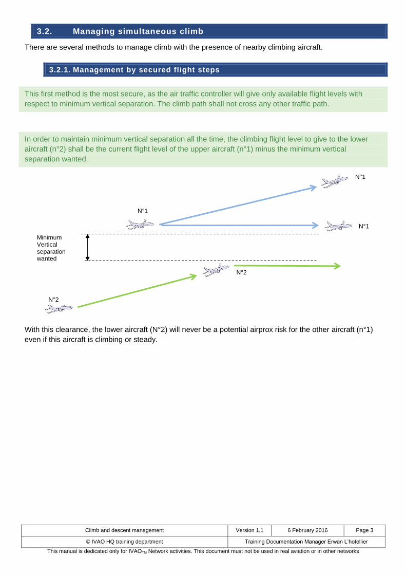
This first method is the most secure, as the air traffic controller will give only available flight levels with
respect to minimum vertical separation. The climb path shall not cross any other traffic path.
In order to maintain minimum vertical separation all the time, the climbing flight level to give to the lower
aircraft (n°2) shall be the current flight level of the upper aircraft (n°1) minus the minimum vertical
separation wanted.
With this clearance, the lower aircraft (N°2) will never be a potential airprox risk for the other aircraft (n°1)
even if this aircraft is climbing or steady.
Minimum Vertical separation wanted
N°1
N°1
N°1
N°2
N°2
Climb and descent management Version 1.1 6 February 2016 Page 4
© IVAO HQ training department Training Documentation Manager Erwan L’hotellier
This manual is dedicated only for IVAOTM Network activities. This document must not be used in real aviation or in other networks
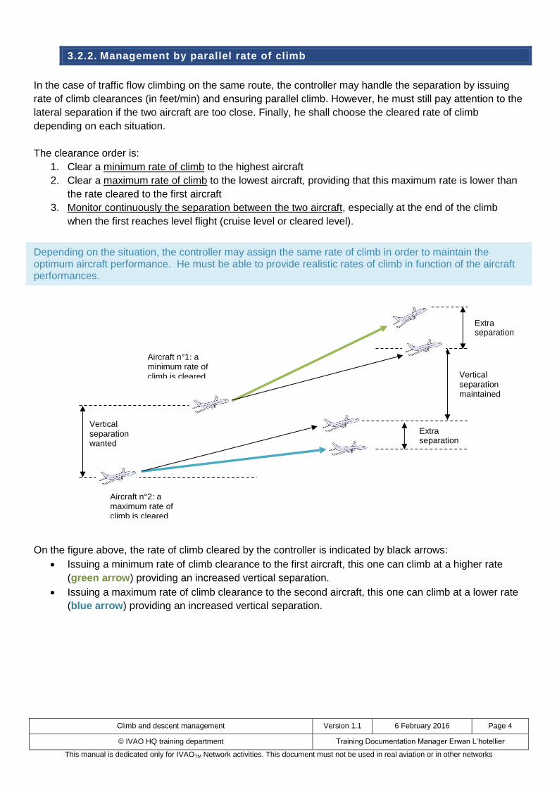
3.2.2. Management by parallel rate of climb
In the case of traffic flow climbing on the same route, the controller may handle the separation by issuing
rate of climb clearances (in feet/min) and ensuring parallel climb. However, he must still pay attention to the
lateral separation if the two aircraft are too close. Finally, he shall choose the cleared rate of climb
depending on each situation.
The clearance order is:
1. Clear a minimum rate of climb to the highest aircraft
2. Clear a maximum rate of climb to the lowest aircraft, providing that this maximum rate is lower than
the rate cleared to the first aircraft
3. Monitor continuously the separation between the two aircraft, especially at the end of the climb
when the first reaches level flight (cruise level or cleared level).
Depending on the situation, the controller may assign the same rate of climb in order to maintain the optimum aircraft performance. He must be able to provide realistic rates of climb in function of the aircraft performances.
On the figure above, the rate of climb cleared by the controller is indicated by black arrows:
Issuing a minimum rate of climb clearance to the first aircraft, this one can climb at a higher rate
(green arrow) providing an increased vertical separation.
Issuing a maximum rate of climb clearance to the second aircraft, this one can climb at a lower rate
(blue arrow) providing an increased vertical separation.
Vertical separation maintained
Vertical separation wanted
Aircraft n°1: a minimum rate of climb is cleared
Extra separation
Extra separation
Aircraft n°2: a maximum rate of climb is cleared
Climb and descent management Version 1.1 6 February 2016 Page 5
© IVAO HQ training department Training Documentation Manager Erwan L’hotellier
This manual is dedicated only for IVAOTM Network activities. This document must not be used in real aviation or in other networks
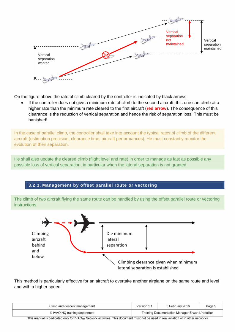
On the figure above the rate of climb cleared by the controller is indicated by black arrows:
If the controller does not give a minimum rate of climb to the second aircraft, this one can climb at a
higher rate than the minimum rate cleared to the first aircraft (red arrow). The consequence of this
clearance is the reduction of vertical separation and hence the risk of separation loss. This must be
banished!
In the case of parallel climb, the controller shall take into account the typical rates of climb of the different
aircraft (estimation precision, clearance time, aircraft performances). He must constantly monitor the
evolution of their separation.
He shall also update the cleared climb (flight level and rate) in order to manage as fast as possible any
possible loss of vertical separation, in particular when the lateral separation is not granted.
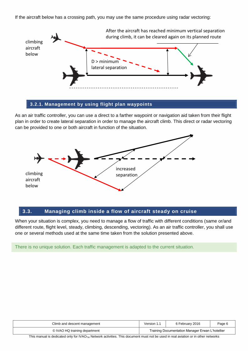
3.2.3. Management by offset parallel route or vectoring
The climb of two aircraft flying the same route can be handled by using the offset parallel route or vectoring
instructions.
This method is particularly effective for an aircraft to overtake another airplane on the same route and level
and with a higher speed.
Vertical separation not maintained
Vertical separation maintained
Vertical separation wanted
D > minimum lateral separation
Climbing aircraft behind and below
Climbing clearance given when minimum lateral separation is established
Climb and descent management Version 1.1 6 February 2016 Page 6
© IVAO HQ training department Training Documentation Manager Erwan L’hotellier
This manual is dedicated only for IVAOTM Network activities. This document must not be used in real aviation or in other networks
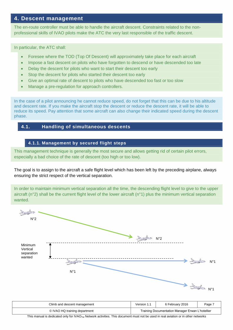
If the aircraft below has a crossing path, you may use the same procedure using radar vectoring:
3.2.1. Management by using flight plan waypoints
As an air traffic controller, you can use a direct to a farther waypoint or navigation aid taken from their flight
plan in order to create lateral separation in order to manage the aircraft climb. This direct or radar vectoring
can be provided to one or both aircraft in function of the situation.
3.3. Managing climb inside a flow of aircraft steady on cruise
When your situation is complex, you need to manage a flow of traffic with different conditions (same or/and
different route, flight level, steady, climbing, descending, vectoring). As an air traffic controller, you shall use
one or several methods used at the same time taken from the solution presented above.
There is no unique solution. Each traffic management is adapted to the current situation.
increased separation
D > minimum lateral separation
climbing
aircraft below
climbing
aircraft below
After the aircraft has reached minimum vertical separation during climb, it can be cleared again on its planned route
Climb and descent management Version 1.1 6 February 2016 Page 7
© IVAO HQ training department Training Documentation Manager Erwan L’hotellier
This manual is dedicated only for IVAOTM Network activities. This document must not be used in real aviation or in other networks
4. Descent management
The en-route controller must be able to handle the aircraft descent. Constraints related to the non-
professional skills of IVAO pilots make the ATC the very last responsible of the traffic descent.
In particular, the ATC shall:
Foresee where the TOD (Top Of Descent) will approximately take place for each aircraft
Impose a fast descent on pilots who have forgotten to descend or have descended too late
Delay the descent for pilots who want to start their descent too early
Stop the descent for pilots who started their descent too early
Give an optimal rate of descent to pilots who have descended too fast or too slow
Manage a pre-regulation for approach controllers.
In the case of a pilot announcing he cannot reduce speed, do not forget that this can be due to his altitude and descent rate. If you make the aircraft stop the descent or reduce the descent rate, it will be able to reduce its speed. Pay attention that some aircraft can also change their indicated speed during the descent phase.
4.1. Handling of simultaneous descents
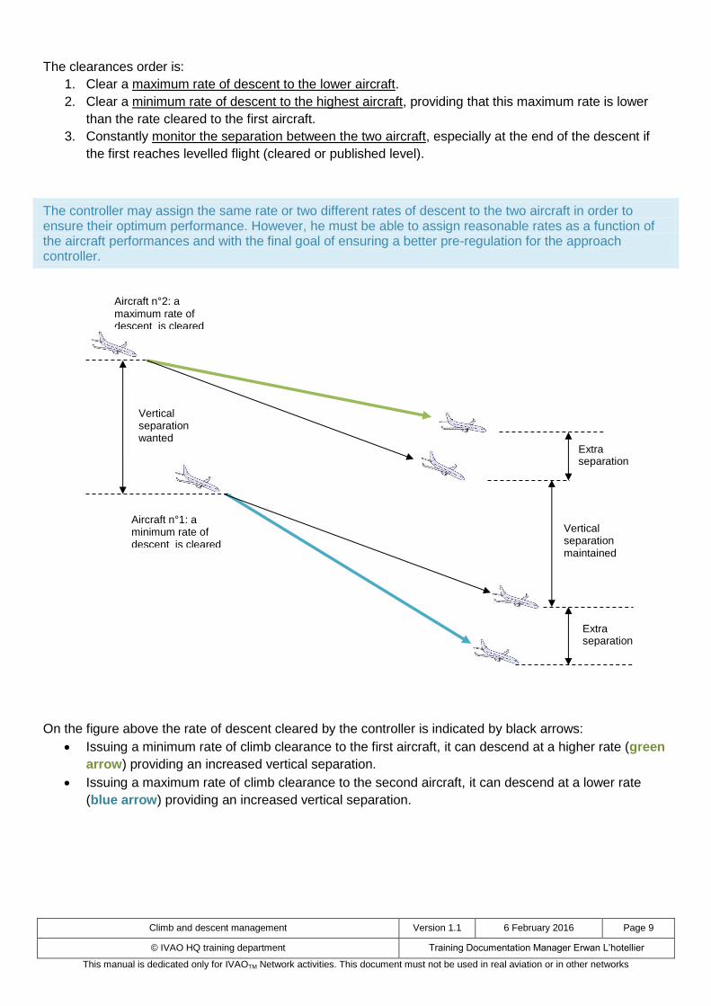
4.1.1. Management by secured flight steps
This management technique is generally the most secure and allows getting rid of certain pilot errors,
especially a bad choice of the rate of descent (too high or too low).
The goal is to assign to the aircraft a safe flight level which has been left by the preceding airplane, always
ensuring the strict respect of the vertical separation.
In order to maintain minimum vertical separation all the time, the descending flight level to give to the upper
aircraft (n°2) shall be the current flight level of the lower aircraft (n°1) plus the minimum vertical separation
wanted.
Minimum Vertical separation wanted
N°1
N°1
N°1
N°2
N°2

Climb and descent management Version 1.1 6 February 2016 Page 8
© IVAO HQ training department Training Documentation Manager Erwan L’hotellier
This manual is dedicated only for IVAOTM Network activities. This document must not be used in real aviation or in other networks
With this clearance, the aircraft below (N°2) will never be a potential airprox risk for the other aircraft (n°1)
even if this aircraft is climbing or steady.
In order to optimize the descent avoiding level flight steps, it is useful to issue complementary clearances in
function of the position of the first aircraft below.
Aircraft n°1, which is at a lower level, can have a lower rate of descent than the other aircraft.
The flight level assigned to aircraft n°2 shall ensure the minimum vertical separation between the two
aircraft, independently of the descent of aircraft n°1.
When aircraft n°2 is close to reach its first cleared level, the controller can clear it to a second lower level,
still keeping the minimum separation between the two aircraft.
This method is the most common and efficient to ensure safe separation during descent.
This is the recommended method at IVAO for beginners.
Please note that the controller must issue the descent clearance to aircraft n°2 anticipating the TOD in order to avoid level flight steps once the first cleared level is reached.
4.2. Management by parallel rate of descent
Another possibility is to handle the descent of the two aircraft without changing their route by managing
their rate of descent to induce a parallel descent with ensuring the minimum separation.
The controller must pay more attention to the lateral separation of the close aircraft. The cleared rate of
descent shall be chosen with care. The goal is to assign the same rate of descent for all descending aircraft
in order to keep them separated during the whole descent.
Minimum Vertical separation wanted
N°1
N°1
N°1
N°2
N°2
N°2
Minimum Vertical separation wanted
Climb and descent management Version 1.1 6 February 2016 Page 9
© IVAO HQ training department Training Documentation Manager Erwan L’hotellier
This manual is dedicated only for IVAOTM Network activities. This document must not be used in real aviation or in other networks
The clearances order is:
1. Clear a maximum rate of descent to the lower aircraft.
2. Clear a minimum rate of descent to the highest aircraft, providing that this maximum rate is lower
than the rate cleared to the first aircraft.
3. Constantly monitor the separation between the two aircraft, especially at the end of the descent if
the first reaches levelled flight (cleared or published level).
The controller may assign the same rate or two different rates of descent to the two aircraft in order to ensure their optimum performance. However, he must be able to assign reasonable rates as a function of the aircraft performances and with the final goal of ensuring a better pre-regulation for the approach controller.
On the figure above the rate of descent cleared by the controller is indicated by black arrows:
Issuing a minimum rate of climb clearance to the first aircraft, it can descend at a higher rate (green
arrow) providing an increased vertical separation.
Issuing a maximum rate of climb clearance to the second aircraft, it can descend at a lower rate
(blue arrow) providing an increased vertical separation.
Vertical separation maintained
Aircraft n°2: a maximum rate of descent is cleared
Extra separation
Extra separation
Aircraft n°1: a minimum rate of descent is cleared
Vertical separation wanted

Climb and descent management Version 1.1 6 February 2016 Page 10
© IVAO HQ training department Training Documentation Manager Erwan L’hotellier
This manual is dedicated only for IVAOTM Network activities. This document must not be used in real aviation or in other networks
On the figure above the rate of descent cleared by the controller is indicated by black arrows:
If the controller does not give a minimum rate of descent to the upper aircraft, it can descend at a
higher rate than the minimum rate cleared to the lower aircraft (red arrow). The consequence of this
clearance is the reduction of vertical separation and hence the risk of separation loss. This must be
banished!
In the case of parallel descent, the controller shall take into account the typical rates of descent of the
different aircraft (estimation precision, clearance time, aircraft performances). He must constantly monitor
the evolution of their separation.
He shall also update the cleared descent (flight level and rate) in order to manage as fast as possible any
possible loss of vertical separation, in particular when the lateral separation is not granted.
Vertical separation not maintained
Vertical separation maintained
Aircraft n°2: a minimum rate of descent is cleared
Vertical separation wanted
Climb and descent management Version 1.1 6 February 2016 Page 11
© IVAO HQ training department Training Documentation Manager Erwan L’hotellier
This manual is dedicated only for IVAOTM Network activities. This document must not be used in real aviation or in other networks
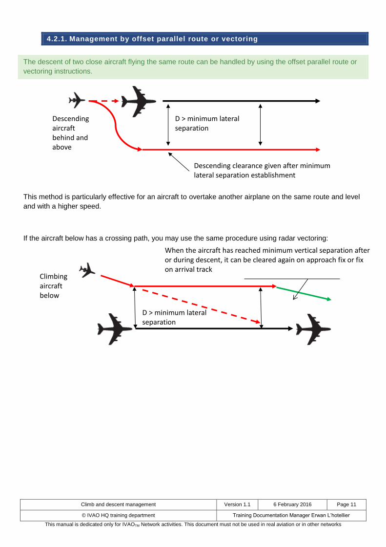
4.2.1. Management by offset parallel route or vectoring
The descent of two close aircraft flying the same route can be handled by using the offset parallel route or
vectoring instructions.
This method is particularly effective for an aircraft to overtake another airplane on the same route and level
and with a higher speed.
If the aircraft below has a crossing path, you may use the same procedure using radar vectoring:
D > minimum lateral separation
Descending aircraft behind and above
Descending clearance given after minimum lateral separation establishment
D > minimum lateral separation
Climbing aircraft below
When the aircraft has reached minimum vertical separation after or during descent, it can be cleared again on approach fix or fix on arrival track
Climb and descent management Version 1.1 6 February 2016 Page 12
© IVAO HQ training department Training Documentation Manager Erwan L’hotellier
This manual is dedicated only for IVAOTM Network activities. This document must not be used in real aviation or in other networks
5. Top of descent calculation
ATC shall monitor the descent and the top of descent point because:
Some pilots forget to descend after the optimal top of descent
Some pilots want to descend a long time before the top of descent
Some pilots use the basic flight simulator descent rate (1800ft/min) and do not adjust it
Some pilots are descending with a too high descent rate
With all these particular type of pilots, ATC must know the basic calculation for top of descent estimation.
Two methods exist:
1. Calculation by the rate of descent (in ft/min)
2. Calculation by the slope (in degrees or percentage)
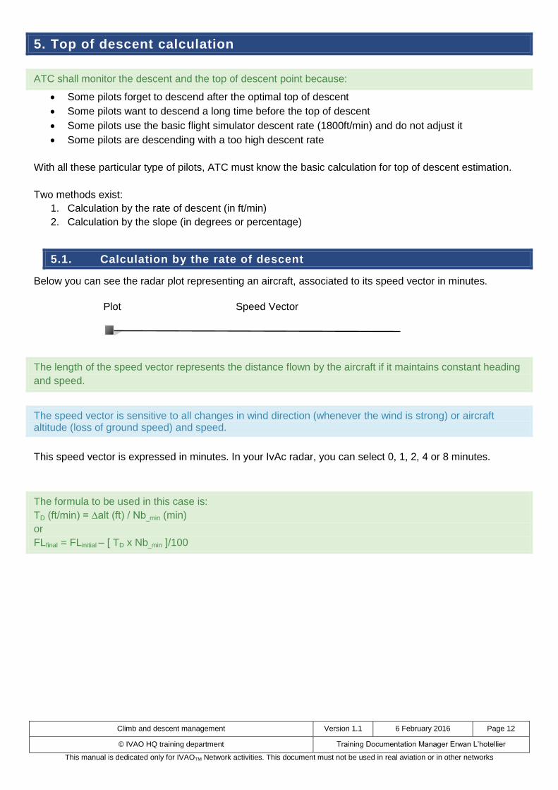
5.1. Calculation by the rate of descent
Below you can see the radar plot representing an aircraft, associated to its speed vector in minutes.
The length of the speed vector represents the distance flown by the aircraft if it maintains constant heading
and speed.
The speed vector is sensitive to all changes in wind direction (whenever the wind is strong) or aircraft altitude (loss of ground speed) and speed.
This speed vector is expressed in minutes. In your IvAc radar, you can select 0, 1, 2, 4 or 8 minutes.
The formula to be used in this case is:
TD (ft/min) = ∆alt (ft) / Nb_min (min)
or
FLfinal = FLinitial – [ TD x Nb_min ]/100
Plot Speed Vector
Climb and descent management Version 1.1 6 February 2016 Page 13
© IVAO HQ training department Training Documentation Manager Erwan L’hotellier
This manual is dedicated only for IVAOTM Network activities. This document must not be used in real aviation or in other networks
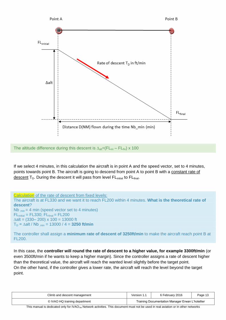
The altitude difference during this descent is alt=(FLini – FLfin) x 100
If we select 4 minutes, in this calculation the aircraft is in point A and the speed vector, set to 4 minutes,
points towards point B. The aircraft is going to descend from point A to point B with a constant rate of
descent TD. During the descent it will pass from level FLinitial to FLfinal.
Calculation of the rate of descent from fixed levels: The aircraft is at FL330 and we want it to reach FL200 within 4 minutes. What is the theoretical rate of descent? Nb_min = 4 min (speed vector set to 4 minutes) FLinitial = FL330; FLfinal = FL200 ∆alt = (330– 200) x 100 = 13000 ft TD = ∆alt / Nb_min = 13000 / 4 = 3250 ft/min The controller shall assign a minimum rate of descent of 3250ft/min to make the aircraft reach point B at FL200.
In this case, the controller will round the rate of descent to a higher value, for example 3300ft/min (or
even 3500ft/min if he wants to keep a higher margin). Since the controller assigns a rate of descent higher
than the theoretical value, the aircraft will reach the wanted level slightly before the target point.
On the other hand, if the controller gives a lower rate, the aircraft will reach the level beyond the target
point.
Climb and descent management Version 1.1 6 February 2016 Page 14
© IVAO HQ training department Training Documentation Manager Erwan L’hotellier
This manual is dedicated only for IVAOTM Network activities. This document must not be used in real aviation or in other networks
Calculation of the estimated arrival level with a fixed rate of descent: The aircraft is at FL280 and the controller wants to give it a rate of descent of 2000ft/min. What will be the level reached within 4 minutes? Nb_min = 4 min (speed vector set to 4 minutes) TD = 2000 ft/min FLinitial = FL280 FLfinal = FLinitial – [ TD x Nb_min ] / 100 = 280 – (2000 x 4) / 100 = 280 – (8000/100) = 280 – 80 = 200 After 4 minutes the aircraft will reach FL200 if it maintains a constant rate of descent of 2000ft/min.
One has to bear in mind that this calculation gives an approximate result. Indeed the aircraft will decrease its ground speed when descending; hence the speed vector will slightly decrease and the descent slope will not be constant. At high altitude and high speed, at the beginning of the descent, the slope will be lower than at low altitude where the ground speed is lower and the descent slope is higher.
5.2. Calculation by the slope
The graphical representation of the case under study is the same as before, but the formula changes. Let’s
then calculate the distance between the estimated top of descent point and the target point to be reached
at a given flight level and with a given slope.
The formula to be used in this case is:
D (NM) = ∆FL (x100ft) / Slope (°)
where the aircraft will have an altitude difference of ∆FL = FLinitial - FLfinal
This method is very useful especially for Airbus pilots who can manage their descent by setting directly a
slope in degrees on their instruments.
Calculation of the distance from the TOD to the target point: An Airbus aircraft is flying at FL260 and the controller wants it to reach a final level of FL120 with a slope of descent of 3°. At which distance from the target point shall he begin its descent? FLinitial = FL260 ; FLfinal = FL120 Slope = 3° ∆FL = 260– 120= 140 (100 ft) D (NM) = ∆FL /Slope = 140 / 3 = 46.7 NM The estimated TOD (Top Of Descent) is then at 46.7NM from the target point.
Again, this calculation is only approximate since it does not take into account the ground speed variations with the altitude or any possible level flight step or wind component variation during descent. Nevertheless, it provides a rather good approximation that can be used to calculate the TOD and manage traffic descents.