clinical experience using sonialvision g4 multi-purpose r
TRANSCRIPT
R/F
No.80 (2016.9)
1. Introduction to Takasago Municipal Hospital
Takasago Municipal Hospital was opened in Takasago City, Hyogo Prefecture, in 1965 through the merger of Arai Hospital and Kokuho Takasago Hospital, and then moved to the current place in 1990.Takasago Municipal Hospital is a regional core hospital that provides advanced and high quality healthcare based on its principle of "Healthcare with Hope," and is a municipal hospital of Takasago City, the birthplace of jo to uba, a man and woman of Japanese folklore who represent peace and long life.
2. Background
Our hospital uses R/F systems in a variety of examinations, including gastrointestinal examinations.A SONIALVISION G4 (hereinafter "G4") was acquired by our hospital in February 2015. In this article, I discuss using the G4 to perform angiographic examinations for a period of approximately 1 month from July 2015, during a period of construction work associated with renewal of the hospital's angiography systems. The article also shows images presented at RSNA 2015.
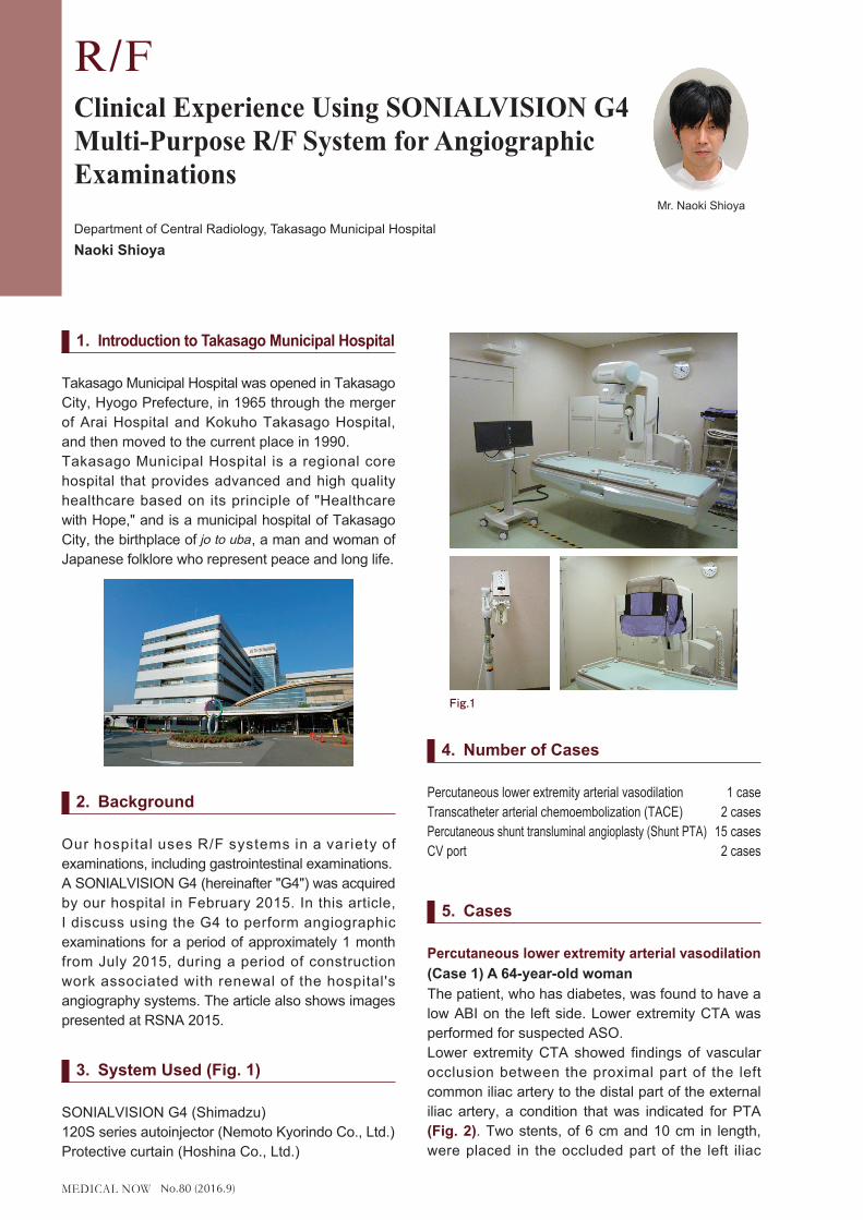
3. System Used (Fig. 1)
SONIALVISION G4 (Shimadzu)120S series autoinjector (Nemoto Kyorindo Co., Ltd.)Protective curtain (Hoshina Co., Ltd.)
4. Number of Cases
Percutaneous lower extremity arterial vasodilation 1 caseTranscatheter arterial chemoembolization (TACE) 2 casesPercutaneous shunt transluminal angioplasty (Shunt PTA) 15 casesCV port 2 cases
5. Cases
Percutaneous lower extremity arterial vasodilation(Case 1) A 64-year-old womanThe patient, who has diabetes, was found to have a low ABI on the left side. Lower extremity CTA was performed for suspected ASO.Lower extremity CTA showed findings of vascular occlusion between the proximal part of the left common iliac artery to the distal part of the external iliac artery, a condition that was indicated for PTA (Fig. 2). Two stents, of 6 cm and 10 cm in length, were placed in the occluded part of the left iliac
Clinical Experience Using SONIALVISION G4 Multi-Purpose R/F System for Angiographic Examinations
Department of Central Radiology, Takasago Municipal HospitalNaoki Shioya
Mr. Naoki Shioya
Fig.1 �

No.80 (2016.9)
artery during PTA. Fig. 3 shows images acquired before and after PTA.
Although the G4 cannot be used for full lower extremity arterial imaging, or so-called stepping angiography, the wide field-of-view FPD of the G4 functioned well throughout the imaged range, and produced fluoroscopic images that showed balloon catheters and stents clearly and in high resolution.
Fig. 4 shows a live image, RSM-DSA* image, and DSA image for comparison. The live image contains sufficient resolution to see the stent. In the DSA image, the vertebral body and stent are invisible as expected, while intestinal gas remains visible. RSM processing of the DSA image creates an image only slightly affected by shadows from the vertebral body, intestinal tract, etc. In particular, intestinal gas is almost invisible after RSM processing.Skilled use of these characteristics is likely to see RSM processing becoming a useful tool in a large number of examinations.
* What is RSM-DSA?RSM-DSA refers to an imaging processing method that uses digital processing to create unsharp images from live images, which are then used as mask images and subtracted from the live images. RSM-DSA is characterized by requiring no mask image, since image subtraction processing is performed repeatedly on each individual frame.
○TACETAE and TACE are treatment methods that inject embolizing material or anticancer drugs through a transcatheter into a selected tumor-bearing artery of a hepatic segment. Identifying the tumor feeding vessel is an important part of this treatment, which can be made difficult due to image blurring caused by patient movement or the patient being unable to hold their breath during imaging. Normally, imaging must be repeated or remask processing performed when these problems occur, but the G4's RSM processing is able to acquire clear images of peripheral vessels with ease, overcoming the challenge of patient-movement. This ability also reduces examination times and reduces patient burden. Cases in which RSM processing was used effectively to identify intratumoral vessels by tumor staining are described below.
(Case 1) An 84-year-old womanDynamic CT revealed 10-mm nodules with high-concentration early enhancement in segments S4 and S8 under the diaphragmatic dome, that showed low-concentration late phase enhancement, were diagnosed as HCC recurrence, and indicated for TACE (Fig. 5).
VR MIPFig.2
Before PTA After PTAFig.3
DSA
Live RSM-DSA
Fig.4 �
Fig.5 Dynamic CT
No.80 (2016.9)
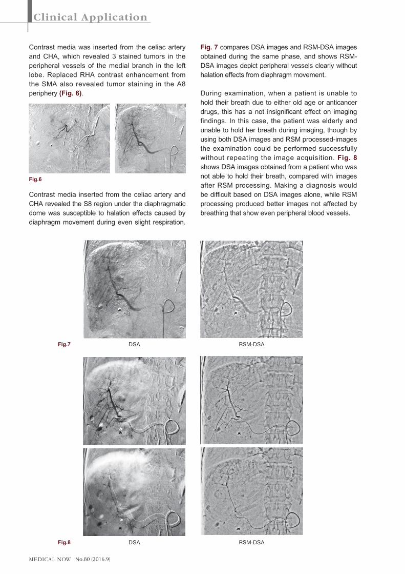
Contrast media was inserted from the celiac artery and CHA, which revealed 3 stained tumors in the peripheral vessels of the medial branch in the left lobe. Replaced RHA contrast enhancement from the SMA also revealed tumor staining in the A8 periphery (Fig. 6).
Contrast media inserted from the celiac artery and CHA revealed the S8 region under the diaphragmatic dome was susceptible to halation effects caused by diaphragm movement during even slight respiration.
Fig. 7 compares DSA images and RSM-DSA images obtained during the same phase, and shows RSM-DSA images depict peripheral vessels clearly without halation effects from diaphragm movement.
During examination, when a patient is unable to hold their breath due to either old age or anticancer drugs, this has a not insignificant effect on imaging findings. In this case, the patient was elderly and unable to hold her breath during imaging, though by using both DSA images and RSM processed-images the examination could be performed successfully without repeating the image acquisition. Fig. 8 shows DSA images obtained from a patient who was not able to hold their breath, compared with images after RSM processing. Making a diagnosis would be difficult based on DSA images alone, while RSM processing produced better images not affected by breathing that show even peripheral blood vessels.
Fig.6
DSA
DSA
RSM-DSA
RSM-DSA
Fig.8
Fig.7
No.80 (2016.9)
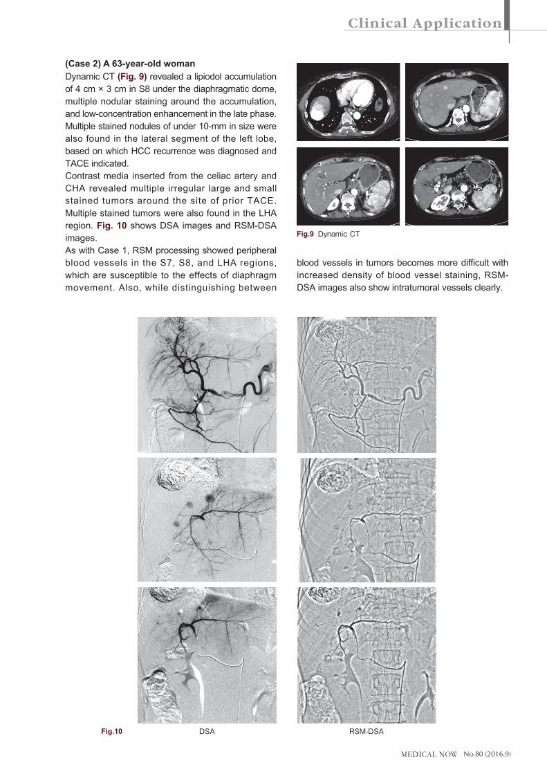
(Case 2) A 63-year-old womanDynamic CT (Fig. 9) revealed a lipiodol accumulation of 4 cm × 3 cm in S8 under the diaphragmatic dome, multiple nodular staining around the accumulation, and low-concentration enhancement in the late phase. Multiple stained nodules of under 10-mm in size were also found in the lateral segment of the left lobe, based on which HCC recurrence was diagnosed and TACE indicated.Contrast media inserted from the celiac artery and CHA revealed multiple irregular large and small stained tumors around the site of prior TACE. Multiple stained tumors were also found in the LHA region. Fig. 10 shows DSA images and RSM-DSA images.As with Case 1, RSM processing showed peripheral blood vessels in the S7, S8, and LHA regions, which are susceptible to the effects of diaphragm movement. Also, while distinguishing between
blood vessels in tumors becomes more difficult with increased density of blood vessel staining, RSM-DSA images also show intratumoral vessels clearly.
Fig.9 Dynamic�CT
DSA RSM-DSAFig.10

No.80 (2016.9)
Fig. 11 compared images of the celiac artery obtained by G4 and our hospital's current angiography system. While it is difficult to compare images obtained from the G4 with 3D images created from cone beam CT images obtained by rotational imaging, as it is difficult to compare the G4 with other systems such as EmboGuide (Philips) in terms of system structure and software, looking at the images shown in Fig. 11 obtained using the G4, they do not fare badly compared to images obtained from the hospital's angiography system.
○�Percutaneous shunt transluminal angioplasty (shunt PTA)
Our hospital also focuses its efforts in the field of nephrology, with a blood purification center containing 40 dialysis beds. There is a long history of dialysis medicine at Takasago Municipal Hospital that began in 1969, and our hospital is considered to be a pioneer in this field in Japan. We also coordinate with other nearby medical facilities, and provide acute care services such as surgeries and medical care for dialysis complications. As a result, we are performing an increasingly large number of percutaneous shunt transluminal angioplasty procedures.Patient positioning during shunt PTA is shown in Fig. 12. Patient position used for right hand shunt and left hand shunt PTA is changed to provide the doctor with working space and to recreate the positioning used during normal angiographic examinations as closely as possible.
(Case 1) A 86-year-old manShunt contrast enhanced imaging was performed due to inadequate blood flow for a right upper extremity dialysis shunt. Contrast media was inserted from the right artery revealing a severe stenosis 4-cm in length from the anastomotic area to the venous side, which
G4
Fig.11 Hospital's Existing Angiography System
Right Hand Shunt
Fig.12
Left Hand Shunt
Before�PTA Balloon Dilatation
After PTA DA after PTAFig.13

No.80 (2016.9)
was indicated for PTA. Fig. 13 shows images before PTA, balloon dilatation, and after PTA.
(Case 2) A 72-year-old manShunt contrast enhanced imaging was performed due to inadequate blood flow for a left upper extremity dialysis shunt. Contrast media was inserted from the left elbow artery revealing severe stenosis of the cephalic vein close to the anastomotic area and at the elbow joint, which was indicated for PTA. Fig. 14 shows images before PTA and after PTA.As shown by Case 1 and Case 2, using a wide field-of-view FPD made it possible to perform imaging from the distal part of the radius to the elbow joint during percutaneous shunt dilatation surgery. However, without a wedge filter, halation prevention is only available by collimation in horizontal and vertical directions. Consequently, it is important to position the patient so their upper extremity is as horizontal as possible and positioned lengthwise on the table, as shown in Fig. 12. Furthermore, when difficulty was encountered in positioning the patient for fluoroscopy-guided guide wire or balloon catheter procedures, adjustments were made to the fluoroscopy conditions (kV, mAs).
○�CV Port(Case 1) A 49-year-old womanFig. 15 shows a left subclavian vein contrast enhanced image and CV port placement image.
6. Summary
Angiographic examinations performed using the G4 provided sufficient resolution in fluoroscopy images to observe the microcatheter ends and stents. However, areas such as the upper extremities that are greatly affected by halation are difficult to render with collimation in horizontal and vertical directions alone, and imaging of these areas is only made possible by adjustment of fluoroscopy conditions.Using both DSA images and RSM-DSA images also allowed us to render blood vessels in patients unable to hold their breath, and complete examinations without repeating the image acquisition. Shorter examination times and reduced patient burden were achieved as a result.For shunt PTA, securing working space for the doctor was a problem until patient positions used for the hospital's angiography system were recreated as closely as possible, which provided more working space for the doctor.Renewal of the angiography systems at our hospital sees a consolidation from separate systems for angiographic examination of the head and abdomen and the cardiovascular system, to a single system for both these areas. This change has been made based on the frequency of system usage. Although faced with the issue of how to manage overlapping examinations, we have confirmed the effectiveness of using the SONIALVISION G4 for angiographic examinations, and consider it a satisfactory back-up angiography system.
Before PTA
Fig.14
After PTA
Port Placement
Live � DSA
Fig.15