closed loop speed control of single phase induction motor ... · closed loop speed control of...
TRANSCRIPT

International Research Journal of Engineering and Technology (IRJET) e-ISSN: 2395 -0056
Volume: 02 Issue: 05 | Aug-2015 www.irjet.net p-ISSN: 2395-0072
© 2015, IRJET ISO 9001:2008 Certified Journal Page 1095
CLOSED LOOP SPEED CONTROL OF SINGLE PHASE INDUCTION MOTOR
USING A NOVEL MULTI LEVEL INVERTER WITH REDUCED NUMBER OF
COMPONENTS
Hima Kiran Kumar Oleti1, Prof. T. Srinivasa Rao2
1 M-tech Student Scholar, Department of Electrical and Electronics Engineering, KKR & KSR Institute of Technology and Science, Guntur(DT), AP, India.
2Professor & H.O.D, Department of Electrical and Electronics Engineering, KKR & KSR Institute of Technology and Science, Guntur(DT), AP, India.
---------------------------------------------------------------------***---------------------------------------------------------------------Abstract - Conventional Multilevel inverters use
numerous DC voltage sources, switches, which occupies
larger installation area and increases converter cost
for high power applications. This is the subject of
increasing importance. Multilevel approach gives ease
of control, good power quality, high voltage capability,
low switching losses. The main disadvantage is
availability of isolated voltage sources or capacitor
banks for small voltage steps and the use of large
number of switches in low voltage applications. The
proposed topology reduces the number of IGBT
switches, voltage sources, with increase in output
voltage levels. The operation and performance of the
proposed inverter is verified by simulation for 31-level
converter. This topology is optimised for utilisation of
minimum number of switches and DC voltage sources.
This optimised topology is applied for speed control of
single phase induction motor drive.
Key Words: Multilevel inverter, less switches, sources,
speed control, induction motor drive
1. INTRODUCTION
The terminology of multilevel inverters was introduced in 1975[1]. This multilevel converter basically is a group of static semiconductor switches used in sequential manner which produce desired ac output from a dc voltage sources. The produced output is a staircase wave form nearer to sinusoidal wave. The more number of steps in the output and less step size decides the power quality, reduces the stress on individual switches, high electromagnetic compatibility, decreasing the switching
losses, increasing the efficiency compared to the conventional converters. The first ever design in this topology was a series H-bridge[1]. The main disadvantage of this topology is utilization of large number of isolated voltage sources. The other conventional multilevel topologies are Diode-clamped[2] in which bank of series capacitors are used .The main drawback in this topology is unequal voltage sharing among the diodes. The flying capacitor multilevel inverter is among the fundamental topologies [3] ,the clamped series capacitors are utilized. It is advanced when compared to Diode clamped (NPC) converter. The problem which restricts it for high voltage applications is large number of storage capacitors for large number of steps. Two switches in this topology should work at peak values of output voltage.
The power quality of the output depends on the number of the output levels. Power quality improves for high level output. The main disadvantage in any conventional topology for large number of output levels is numerous switches, DC voltage sources or capacitor banks, triggering circuits, other auxiliary equipment, large installation area, high switching losses which gives low converter efficiency. To overcome the above mentioned disadvantages researchers introduced new topologies [4]. This topology consists of series connected sub multilevel converter blocks. The output voltage levels depend on the number of components used. The main disadvantage is large number of bidirectional switches which have high blocking voltages. A new topology was introduced to over come the above mentioned disadvantages [5]. similar topology with some changes is also introduced[6]. In these two topologies the main disadvantage is utilization of unidirectional switches which operate at high voltages for single phase applications, this goes along with the design

International Research Journal of Engineering and Technology (IRJET) e-ISSN: 2395 -0056
Volume: 02 Issue: 05 | Aug-2015 www.irjet.net p-ISSN: 2395-0072
© 2015, IRJET ISO 9001:2008 Certified Journal Page 1096
complexity. For high voltage applications the switches operate at high peak voltages , the transformers utilised are costlier and bulky . In this paper a new topology of cascaded multilevel inverter is proposed with less number of isolated voltage sources and switching components. This proposed topology is optimised for utilization of minimal components. The popular conventional controllers are P, PI, PID controllers. Among them PI controller is one which is mostly used by the researchers [7] as optimal controller for their applications. In this paper this methodology is used for closed loop speed control. In the feedback PI controller is used to convert error signal into control signal. Finally a design example of the proposed new topology and a PI controller is included.
2. NEW TOPOLOGY
Figure. 1 shows the proposed topology for a submultilevel converter, which consists of the basic unit and a full-bridge converter. The basic unit consists of n dc voltage sources. Each dc voltage source is connected to the output by two switches and can produce a zero or positive polarity voltage. As shown in Fig. 1, each switch is composed of an insulated gate bipolar transistor (IGBT) with an antiparallel diode. Both switches, Si and  ̄ Si (for i = 1, 2, . . . , n), are complementary controlled on the entire operation cycle. The basic unit produces a staircase voltage waveform with positive polarity. The output voltage of the basic unit can be equal to each dc voltage source or binary, ternary, . . . , or n’ nary combinations of the dc voltage sources. Therefore, the maximum number of output voltage steps for v_ o is equal to 2n − 1. The output side of the basic unit is connected to a single-phase full-bridge converter, which alternates the input voltage polarity and provides a positive or negative staircase waveform at the output. The full-bridge switches, T1 , ̄
T1 , T2 , and  ̄ T2 , are also complementary controlled. The typical output waveforms of v_o and vo are shown in Fig. 1(b). Table I gives the values of voltages v_o and vo for different states of the switches S1 , S2, . . . , Sn , T1 , and T2 . For simplicity, the on-statevoltage drops of the switches have been neglected. As can be seen, 2n+1 − 1 different values can be obtained for vo . It can be mentioned that there are different switching states to generate the zero-voltage level at the output voltage. In Table I, one state is presented. The proposed multilevel converter topology is constituted by a cascade connection of submultilevel converters as shown in Fig. 2. The structure of the first, second, . . . and kth basic unit have 2n1 , 2n2 , . . . , and 2nk switches, respectively.
Fig -1:(a) Proposed submultilevel topology and (b) typical output waveforms of vo .
Table -1: values of vo for different states of the switches

International Research Journal of Engineering and Technology (IRJET) e-ISSN: 2395 -0056
Volume: 02 Issue: 05 | Aug-2015 www.irjet.net p-ISSN: 2395-0072
© 2015, IRJET ISO 9001:2008 Certified Journal Page 1097
Fig -2: Proposed multilevel converter topology The full-bridge converters provide positive or negative stepped voltage waveforms between the output terminals. The overall output voltage of the proposed cascaded multilevel converter is the sum of output voltages of the submultilevel converters as follows vo = vo1 + vo2 + … + vok . (1) The different output voltage levels can be determined by combinations of switching states of each unit. If proper values for the dc voltage sources are selected, then the output voltage of the converter can be obtained. If the number of dc voltage sources in basic units is considered equal to 1, then there is no need for switches in basic units. In this state, the dc voltage source is directly connected to the full-bridge converter. In other words, this topology is equivalent to the CHB converter. Although the latter topology requires multiple dc sources, but these may be suitable for the cases, which have possible combination of photovoltaic panels, fuel cells, or energy storage devices, such as capacitors or batteries. When ac voltage is available, multiple dc sources can be generated using isolated transformers and rectifiers [4]. It is important to mention that this topology requires less dc voltage sources considering variety and number compared to topologies presented in [4] and [5]. This is a great advantage in practice, as it will be shown in the following sections.
3. DETERMINATION OF THE MAGNITUDES OF THE DC VOLTAGE SOURCES To provide a large number of output steps without increasing the number of inverters, asymmetric structures can be used. In [7], dc voltage sources in conventional cascaded multilevel inverters have been proposed to be chosen according to a geometric progression with a factor of 2 or 3. In fact, a proper choice of voltage asymmetry among cells can produce a different combination of
voltage levels and eliminate redundancies. For the proposed topology, in order to have unequal values for vo and produce linear steps, three different methods for the determination of magnitudes of the dc voltage sources are presented. To produce a specific number of output steps, the number of dc voltage sources is decreased from the first- to the third proposed method. But, the variety of magnitudes of dc voltage sources is increased. This is one of the important problems for asymmetric structures of multilevel converters. It is noticeable that for all proposed methods, any number of output voltage steps (even and odd) can be produced.
Vm1 = V11 + (2a) Vmi = 2(i+1) Vm1 (2b)
The peak value of the output voltage is obtained as follows:
Vm1 = = (3) The number of output voltage steps can be determined by the following equation:
Nstep = (4)
4. OPTIMAL STRUCTURES In the proposed topology, there are different submultilevels arrangements for a specified number of dc voltage sources to obtain different number of steps at the output voltage and utilizing a different number of switches. It is worthwhile to notice that the number of submultilevel converters and components can be chosen in order to obtain an optimal structure for each special objective. This leads to the reduction in the cost, weight, and installation area of the converter. In this section, these optimal structures are investigated.
4.2. Optimal Structure for Maximum Number of Voltage Steps With Constant Number of Switches The desirable objective in a multilevel converter is to obtain the maximum number of steps for minimum number of switches. If the number of switches Nswitch is constant in the proposed topology, then, the maximum number of output voltage step should be determined. Suppose that the proposed topology consists of a series of k submultilevel converters and each of these has ni dc voltage sources (i = 1, 2, . . . , k), then, we have

International Research Journal of Engineering and Technology (IRJET) e-ISSN: 2395 -0056
Volume: 02 Issue: 05 | Aug-2015 www.irjet.net p-ISSN: 2395-0072
© 2015, IRJET ISO 9001:2008 Certified Journal Page 1098
= 2( + )+4k (5) To determine the dc voltage sources V11 =Base Voltage (6) Vni = V(n-1)i + V(n-1)(i+1) for n=2 2 = V(n-1)i + V(n-2)(i) for n>2 (7 ) 2 The peak value of the voltage is given by n Vp = ∑ V1i (8) i=1 The number of output levels is given by NL= 2(i+1)-1 (9) Total number of switches is given by Ns = (2i+4)n (10)
5. DESIGN OF MULTILEVEL CONVERTER BASED ON PROPOSED TOPOLOGY The optimal multilevel structure is presented in Fig.(3) for the minimum number of components used. As shown in this figure, the number of IGBTs used are 12, the number of isolated voltage sources used are 4, the number of output levels are 31.
Fig -3: optimal multilevel structure Thirty one level output
6. MATLAB MODELING AND SIMULATION RESULTS Here simulation is carried out in different cases with respect to reduced components, 1). Proposed Reduced Switch Count MLI Topology Applied to Induction Machine without PI Regulator 2). Proposed Reduced Switch Count MLI Topology Applied to Induction Machine with PI Regulator.
Case 1: Proposed Reduced Switch Count MLI Topology Applied to Induction Machine without PI Regulator
Fig -4: Matlab/Simulink Model of Proposed Reduced Switch Count MLI Topology Applied to Induction Machine without PI Regulator
Fig -5: 31-Level Output Voltage Fig.5 31-Level Output Voltage of Proposed Reduced Switch Count MLI Topology Applied to Induction Machine without PI Regulator.
Fig -6: FFT Analysis of 31-Level Output Voltage
International Research Journal of Engineering and Technology (IRJET) e-ISSN: 2395 -0056
Volume: 02 Issue: 05 | Aug-2015 www.irjet.net p-ISSN: 2395-0072
© 2015, IRJET ISO 9001:2008 Certified Journal Page 1099
Fig.6 FFT Analysis of 31-Level Output Voltage of Proposed Reduced Switch Count MLI Topology Applied to Induction Machine without PI Regulator, attain 12.43%.
Fig -7: Induction Machine Speed Fig.7 Induction Machine Speed of Proposed Reduced Switch Count MLI Topology Applied to Induction Machine without PI Regulator.
Case 2: Proposed Reduced Switch Count MLI Topology Applied to Induction Machine with PI Regulator.
Fig -8: Matlab/Simulink Model of Proposed Reduced Switch Count MLI Topology Applied to Induction Machine with PI Regulator
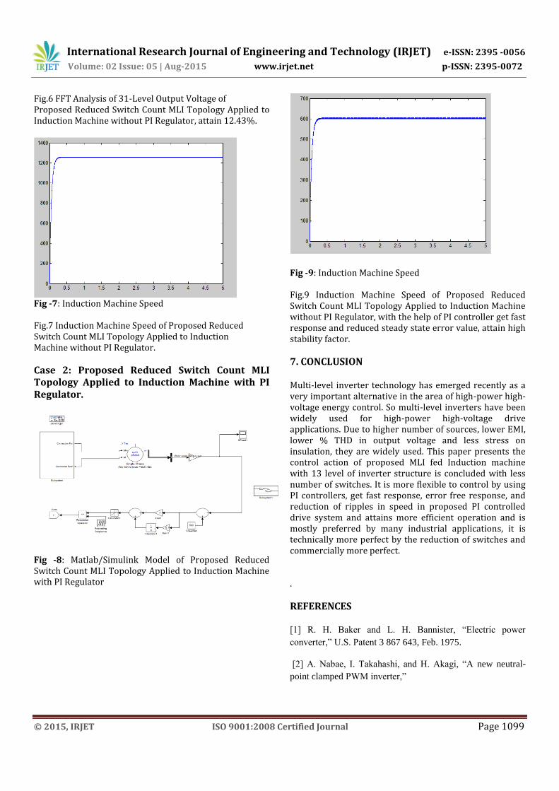
Fig -9: Induction Machine Speed Fig.9 Induction Machine Speed of Proposed Reduced Switch Count MLI Topology Applied to Induction Machine without PI Regulator, with the help of PI controller get fast response and reduced steady state error value, attain high stability factor.
7. CONCLUSION Multi-level inverter technology has emerged recently as a very important alternative in the area of high-power high-voltage energy control. So multi-level inverters have been widely used for high-power high-voltage drive applications. Due to higher number of sources, lower EMI, lower % THD in output voltage and less stress on insulation, they are widely used. This paper presents the control action of proposed MLI fed Induction machine with 13 level of inverter structure is concluded with less number of switches. It is more flexible to control by using PI controllers, get fast response, error free response, and reduction of ripples in speed in proposed PI controlled drive system and attains more efficient operation and is mostly preferred by many industrial applications, it is technically more perfect by the reduction of switches and commercially more perfect. .
REFERENCES [1] R. H. Baker and L. H. Bannister, “Electric power
converter,” U.S. Patent 3 867 643, Feb. 1975.
[2] A. Nabae, I. Takahashi, and H. Akagi, “A new neutral-
point clamped PWM inverter,”

International Research Journal of Engineering and Technology (IRJET) e-ISSN: 2395 -0056
Volume: 02 Issue: 05 | Aug-2015 www.irjet.net p-ISSN: 2395-0072
© 2015, IRJET ISO 9001:2008 Certified Journal Page 1100
[4] E. Babaei, “A cascade multilevel converter topology
with reduced number of switches,” IEEE Trans. Power
Electron, vol. 23, no. 6, pp. 2657–2664, Nov. 2008.
[5] E. Babaei and S. H. Hosseini, “New cascaded multilevel
inverter topology with minimum number of switches,”
Elsevier J. Energy Convers. Manage., vol. 50, no. 11, pp.
2761–2767, Nov. 2009.
[6] R. Marquardt, “Modular multilevel converter: An
universal concept for HVDC-Networks and extendedDC-
Bus-applications,” in Proc. Int. Power Electron. Conf., 2010,
Jun. 2010.
[7] M. Manjrekar and T. A. Lipo, “A hybrid multilevel
inverter topology fordrive Application,” in Proc. Appl.
Power Electron. Conf. Expo., 1998, pp. 523–529.
[8] P. Lezana, J. Pou, T. A. Meynard, J. Rodriguez, S.
Ceballos, and F. Richardeau, “Survey on fault operation on
multilevel inverters,” IEEE Trans. Ind. Electron, vol. 57, no.
7, pp. 2207–2218, Jul. 2010.
[9] C. Rech and J. R. Pinheiro, “Hybrid multilevel
converters: Unified analysis and design considerations,”
IEEE Trans. Ind. Electron., vol. 54, no. 2, pp. 1092–1104,
Apr. 2007. [10] C. Rech and J. R. Pinheiro, “Line current
harmonics reduction in multipulse connection of
asymmetrically loaded rectifiers,” IEEE Trans. Ind.
Electron., vol. 52, no. 3, pp. 640–652, Jun. 2005.
[11] K.N.V. Prasad, G.Ranjith Kumar, Y.S. Anil Kumar, G.
Satyanarayana, "Realization of cascaded H-bridge 5-Level
multilevel inverter as Dynamic Voltage Restorer,"
Computer Communication and Informatics (ICCCI), 2013
International Conference on , vol., no.,pp.1,6, 4-6 Jan. 2013.
[12] T. J. Kim, D. W. Kang, Y. H. Lee, and D. S. Hyun, “The
analysis of conduction and switching losses in multi-level
inverter system,” in Proc. Power Eletron. Spec. Conf., 2001,
pp. 1363–1368. [13] J. I. Leon, S. Vazquez, S. Kouro, L. G.
Franquelo, J. M. Carrasco, and J. Rodriguez,
“Unidimensional modulation technique for cascaded
multilevel converters,” IEEE Trans. Ind. Electron., vol. 56,
no. 8, pp. 2981– 2986, Aug. 2009.
[14] P. Cortes, A. Wilson, S. Kouro, J. Rodriguez, and H.
Abu-Rub, “Model predictive control of multilevel cascaded
H-bridge inverters,” IEEE Trans. Ind. Electron., vol. 57, no.
8, pp. 2691–2699, Aug. 2010.