cloudstack 完全ドキュメント apache cloudstack...
TRANSCRIPT
Apache CloudStack 4.1.0
CloudStack 完全ドキュメント
open source cloud com put ing
CloudStack Apache [FAMILY Given]
CloudStack 完全ドキュメント
Apache CloudStack 4.1.0 CloudStack 完全ドキュメント著者 CloudStack Apache [FAMILY
Given]
Licensed to the Apache Software Foundation (ASF) under one or more contributor licenseagreements. See the NOTICE file distributed with this work for additional information regardingcopyright ownership. The ASF licenses this file to you under the Apache License, Version 2.0 (the"License"); you may not use this file except in compliance with the License. You may obtain a copyof the License at
http://www.apache.org/licenses/LICENSE-2.0
Unless required by applicable law or agreed to in writing, software distributed under the Licenseis distributed on an "AS IS" BASIS, WITHOUT WARRANTIES OR CONDITIONS OF ANY KIND, eitherexpress or implied. See the License for the specific language governing permissions and limitationsunder the License.
Apache CloudStack is an effort undergoing incubation at The Apache Software Foundation (ASF).
Incubation is required of all newly accepted projects until a further review indicates thatthe infrastructure, communications, and decision making process have stabilized in a mannerconsistent with other successful ASF projects. While incubation status is not necessarily a reflectionof the completeness or stability of the code, it does indicate that the project has yet to be fullyendorsed by the ASF.
CloudStack 完全ドキュメント
iii
1. コンセプト 11.1. CloudStack とは .......................................................................................................... 11.2. CloudStack の機能 ...................................................................................................... 11.3. 展開アーキテクチャの概要 .............................................................................................. 2
1.3.1. 管理サーバーについて ........................................................................................ 31.3.2. クラウドインフラストラクチャの概要 ........................................................................ 41.3.3. ネットワーク ........................................................................................................ 5
2. クラウドインフラストラクチャのプロビジョニング 72.1. リージョンについて ......................................................................................................... 72.2. ゾーンについて .............................................................................................................. 72.3. ポッドについて ............................................................................................................... 92.4. クラスタについて ........................................................................................................... 92.5. ホストについて ............................................................................................................ 102.6. プライマリストレージについて ......................................................................................... 112.7. セカンダリストレージについて ........................................................................................ 112.8. 物理ネットワークについて .............................................................................................. 11
2.8.1. 基本ゾーンのネットワークトラフィックの種類 .......................................................... 122.8.2. 基本ゾーンのゲスト IP アドレス .......................................................................... 132.8.3. 拡張ゾーンのネットワークトラフィックの種類 .......................................................... 132.8.4. 拡張ゾーンのゲスト IP アドレス .......................................................................... 132.8.5. 拡張ゾーンのパブリック IP アドレス ..................................................................... 132.8.6. システムにより予約済みの IP アドレス ................................................................. 14
3. インストール 153.1. 対象の読者 ................................................................................................................ 153.2. インストール手順の概要 ............................................................................................... 153.3. 最小システム要件 ........................................................................................................ 15
3.3.1. 管理サーバー, データベースとストレージシステムの要件 ........................................ 153.3.2. ホスト/ハイパーバイザーの要件 .......................................................................... 16
3.4. リポジトリの設定 ......................................................................................................... 173.4.1. DEBパッケージのリポジトリ ................................................................................ 173.4.2. RPM package repository ................................................................................ 17
3.5. 管理サーバーのインストール ......................................................................................... 183.5.1. 管理サーバーのインストール .............................................................................. 183.5.2. オペレーティングシステムの準備 ......................................................................... 183.5.3. 初期ホストへの管理サーバーのインストール ......................................................... 193.5.4. Install the database server ............................................................................. 203.5.5. About Password and Key Encryption ............................................................. 253.5.6. NFS共有の準備 ............................................................................................... 263.5.7. 追加の管理サーバーの準備と起動 ...................................................................... 293.5.8. システム仮想マシンテンプレートの準備 ................................................................ 303.5.9. インストールが完了したら次の手順に進みます。 ..................................................... 31
3.6. Building RPMs from Source ...................................................................................... 313.6.1. Generating RPMS .......................................................................................... 32
3.7. DEBパッケージのビルド ................................................................................................ 333.7.1. APTリポジトリの設定 ........................................................................................ 343.7.2. APTリポジトリの設定 ........................................................................................ 35
3.8. Apache CloudStack の構築に必要なもの ..................................................................... 35
4. ユーザーインターフェイス 374.1. UIへのログイン ........................................................................................................... 37
4.1.1. End User's UI Overview ................................................................................. 37
CloudStack 完全ドキュメント
iv
4.1.2. Root Administrator's UI Overview .................................................................. 374.1.3. ルート管理者としてのログイン ............................................................................. 374.1.4. ルートパスワードの変更 ..................................................................................... 38
4.2. Using SSH Keys for Authentication ........................................................................... 394.2.1. Creating an Instance Template that Supports SSH Keys ................................. 394.2.2. Creating the SSH Keypair .............................................................................. 404.2.3. Creating an Instance ..................................................................................... 414.2.4. Logging In Using the SSH Keypair ................................................................. 414.2.5. Resetting SSH Keys ....................................................................................... 41
5. Steps to Provisioning Your Cloud Infrastructure 435.1. プロビジョニングの概要 ................................................................................................ 435.2. リージョンの追加 (オプション) ........................................................................................ 44
5.2.1. 1つめのリージョン: デフォルトリージョン ............................................................... 445.2.2. リージョンの追加 .............................................................................................. 445.2.3. 3番めのリージョンの追加 .................................................................................. 455.2.4. リージョンの削除 .............................................................................................. 47
5.3. ゾーンの追加 .............................................................................................................. 475.3.1. 基本ゾーンの構成 ............................................................................................ 485.3.2. 拡張ゾーンの構成 ............................................................................................ 52
5.4. ポッドの追加 ............................................................................................................... 565.5. クラスタの追加 ............................................................................................................ 57
5.5.1. クラスターの追加:KVM または XenServer .......................................................... 575.5.2. クラスターの追加:vSphere ................................................................................ 57
5.6. ホストの追加 .............................................................................................................. 595.6.1. ホストの追加(XenServer または KVM) ............................................................... 605.6.2. ホストの追加 (vSphere) .................................................................................... 62
5.7. プライマリストレージの追加 ........................................................................................... 625.7.1. プライマリストレージのシステム要件 .................................................................... 625.7.2. プライマリストレージの追加 ................................................................................ 62
5.8. セカンダリストレージの追加 .......................................................................................... 635.8.1. セカンダリストレージのシステム要件 .................................................................... 635.8.2. セカンダリストレージの追加 ............................................................................... 64
5.9. 初期化とテスト ............................................................................................................ 64
6. Global Configuration Parameters 676.1. グローバル構成パラメーターの設定 ............................................................................... 676.2. About Global Configuration Parameters ................................................................... 67
7. Hypervisor Installation 717.1. KVM のインストールと構成 ........................................................................................... 71
7.1.1. KVM ホストのシステム要件 ............................................................................... 717.1.2. KVM インストールの概要s ................................................................................. 717.1.3. オペレーティングシステムの準備 ......................................................................... 727.1.4. エージェントのインストールと設定 ....................................................................... 737.1.5. libvirt の構成とインストール .............................................................................. 737.1.6. Configure the Security Policies ...................................................................... 747.1.7. Configure the network bridges ...................................................................... 757.1.8. Configure the network using OpenVswitch .................................................... 787.1.9. Configuring the firewall ................................................................................. 817.1.10. CloudStack へのホスト追加 ........................................................................... 82
7.2. CloudStackのためのCitrix XenServerのインストール ..................................................... 827.2.1. XenServerホストのシステム要件 ........................................................................ 82
v
7.2.2. XenServerのインストール手順 ........................................................................... 837.2.3. XenServer ドメイン0のメモリ設定 ...................................................................... 847.2.4. ユーザー名とパスワード ..................................................................................... 847.2.5. 時刻同期 ........................................................................................................ 847.2.6. ライセンス設定 ................................................................................................. 847.2.7. CloudStack XenServer Support Pakcage(CSP)のインストール ........................... 857.2.8. XenServer 用のプライマリストレージのセットアップ ............................................... 867.2.9. XenServer の iSCSI マルチパスのセットアップ(オプション) ..................................... 877.2.10. XenServer の物理ネットワーク設定 .................................................................. 877.2.11. XenServer バージョンのアップグレード .............................................................. 91
7.3. VMware vSphereのインストールと構成 ......................................................................... 947.3.1. vSphere ホストのシステム要件 .......................................................................... 947.3.2. VMware 向けチェックリストを用意します。 ............................................................ 967.3.3. vSphereのインストール手順 .............................................................................. 977.3.4. ESXiホストセットアップ ...................................................................................... 977.3.5. 物理ホストのネットワーク ................................................................................... 977.3.6. Storage Preparation for vSphere (iSCSI only) ............................................... 1027.3.7. Add Hosts or Configure Clusters (vSphere) .................................................. 1067.3.8. Applying Hotfixes to a VMware vSphere Host .............................................. 106
8. Additional Installation Options 1098.1. 使用状況測定サーバーのインストール(オプション) .......................................................... 109
8.1.1. 使用状況測定サーバーのインストール要件 ........................................................ 1098.1.2. 使用状況測定サーバーのインストール手順 ........................................................ 109
8.2. SSL (Optional) ........................................................................................................ 1098.3. Database Replication (Optional) ............................................................................. 110
8.3.1. Failover ....................................................................................................... 112
9. 展開アーキテクチャの選択 1139.1. 小規模な展開 ........................................................................................................... 1139.2. 大規模な冗長セットアップ ........................................................................................... 1149.3. 別個のストレージネットワーク ...................................................................................... 1159.4. 複数ノードの管理サーバー .......................................................................................... 1159.5. 複数サイトの展開 ...................................................................................................... 115
10. アカウント 11910.1. アカウント、ユーザー、およびドメイン ............................................................................ 11910.2. LDAP サーバーによるユーザー認証 ........................................................................... 119
10.2.1. Example LDAP Configuration Commands .................................................. 12010.2.2. Search Base .............................................................................................. 12110.2.3. Query Filter ............................................................................................... 12110.2.4. Search User Bind DN ................................................................................ 12110.2.5. SSL キーストアのパスとパスワード .................................................................. 122
11. User Services Overview 12311.1. Service Offerings, Disk Offerings, Network Offerings, and Templates ..................... 123
12. プロジェクトによるユーザーとリソースの組織化 12512.1. プロジェクトの概要 .................................................................................................. 12512.2. プロジェクトの構成 .................................................................................................. 125
12.2.1. 招待状のセットアップ .................................................................................... 12512.2.2. Setting Resource Limits for Projects .......................................................... 12612.2.3. プロジェクト作成者の権限の設定 .................................................................... 128
12.3. 新しいプロジェクトの作成 ......................................................................................... 128
CloudStack 完全ドキュメント
vi
12.4. プロジェクトへのメンバーの追加 ................................................................................ 12912.4.1. プロジェクトメンバーになるための招待状の送信 ............................................... 12912.4.2. ユーザーインターフェイスでのメンバーの追加 .................................................... 129
12.5. メンバー招待の受理 ................................................................................................ 13012.6. プロジェクトの一時停止または削除 ............................................................................ 13012.7. プロジェクトビューの使用方法 ................................................................................... 130
13. サービスオファリング 13313.1. Compute and Disk Service Offerings .................................................................... 133
13.1.1. 新しいコンピューティングオファリングの作成 ..................................................... 13313.1.2. ディスクオファリングの作成 ............................................................................. 13413.1.3. Modifying or Deleting a Service Offering ................................................... 135
13.2. System Service Offerings ...................................................................................... 13513.2.1. Creating a New System Service Offering .................................................... 135
13.3. Network Throttling ............................................................................................... 13613.4. Changing the Default System Offering for System VMs ......................................... 138
14. Setting Up Networking for Users 14114.1. Overview of Setting Up Networking for Users ....................................................... 14114.2. 仮想ネットワークについて .......................................................................................... 141
14.2.1. 分離ネットワーク ........................................................................................... 14114.2.2. 共有ネットワーク ........................................................................................... 14114.2.3. 仮想ネットワークリソースの実行時割り当て ...................................................... 142
14.3. ネットワークサービスプロバイダー .............................................................................. 14214.4. ネットワークオファリング ............................................................................................ 143
14.4.1. 新しいネットワークオファリングの作成 .............................................................. 144
15. 仮想マシンの操作 14715.1. 仮想マシンの操作 ................................................................................................... 14715.2. Best Practices for Virtual Machines ...................................................................... 14715.3. 仮想マシンのライフサイクル ...................................................................................... 14815.4. VMの作成 .............................................................................................................. 14815.5. 仮想マシンへのアクセス ........................................................................................... 14915.6. 仮想マシンの停止と起動 .......................................................................................... 15015.7. 仮想マシン、OS、グループの名前変更 ......................................................................... 15015.8. 仮想マシンのサービスオファリングの変更 .................................................................... 15115.9. ホスト間の仮想マシンの移動(手動ライブマイグレーション) ............................................ 15115.10. 仮想マシンの削除 ................................................................................................. 15215.11. ISO に関わる作業 ................................................................................................. 152
15.11.1. ISO の追加 ............................................................................................... 15215.11.2. 仮想マシンへのISOのアタッチ ...................................................................... 154
16. ホストの操作 15516.1. ホストの追加 .......................................................................................................... 15516.2. ホストの計画保守と保守モード .................................................................................. 155
16.2.1. vCenter と保守モード .................................................................................. 15516.2.2. XenServer と保守モード ............................................................................... 155
16.3. ゾーン、ポッド、およびクラスターの無効化と有効化 ........................................................ 15616.4. ホストの削除 .......................................................................................................... 156
16.4.1. XenServer および KVM ホストの削除 ............................................................ 15716.4.2. vSphere ホストの削除 .................................................................................. 157
16.5. Re-Installing Hosts ............................................................................................... 15716.6. ハイパーバイザーホストの維持 .................................................................................. 157
vii
16.7. Changing Host Password ...................................................................................... 15716.8. ホストの割り当て ..................................................................................................... 158
16.8.1. オーバープロビジョニングとサービスオファリングの制限 ..................................... 15816.9. VLAN プロビジョニング ............................................................................................ 159
17. テンプレートと動作 16117.1. テンプレートの作成:概要 .......................................................................................... 16117.2. テンプレートの要件 .................................................................................................. 16117.3. テンプレートのベストプラクティス ............................................................................... 16117.4. デフォルトのテンプレート .......................................................................................... 16117.5. プライベートテンプレートとパブリックテンプレート ......................................................... 16217.6. 既存の仮想マシンからのテンプレートの作成 ............................................................... 16217.7. スナップショットからのテンプレートの作成 ................................................................... 16317.8. テンプレートのアップロード ........................................................................................ 16317.9. テンプレートのエクスポート ....................................................................................... 16517.10. Windows テンプレートの作成 ................................................................................ 165
17.10.1. Windows Server 2008 R2 の Sysprep ...................................................... 16517.10.2. Windows Server 2003 R2 用 システム準備 ................................................ 169
17.11. AMI のインポート .................................................................................................. 17017.12. Hyper-V 仮想マシンのテンプレートへの変換 ............................................................ 17317.13. テンプレートへのパスワード管理機能の追加 ............................................................. 175
17.13.1. Linux オペレーティングシステムのインストール ............................................... 17517.13.2. Window オペレーティングシステムのインストール ........................................... 175
17.14. テンプレートの削除 ................................................................................................ 176
18. Working With Storage 17718.1. ストレージについて .................................................................................................. 17718.2. プライマリストレージ ................................................................................................. 177
18.2.1. Best Practices for Primary Storage ............................................................. 17718.2.2. Runtime Behavior of Primary Storage ........................................................ 17718.2.3. ハイパーバイザーのプライマリストレージサポート ............................................... 17718.2.4. ストレージタグ .............................................................................................. 17818.2.5. プライマリストレージの保守モード ................................................................... 178
18.3. セカンダリストレージ ................................................................................................ 17918.4. Working With Volumes ......................................................................................... 179
18.4.1. 新しいボリュームの作成 ................................................................................. 17918.4.2. Uploading an Existing Volume to a Virtual Machine ................................... 18018.4.3. ボリュームのアタッチ ..................................................................................... 18118.4.4. Detaching and Moving Volumes ................................................................ 18218.4.5. VM Storage Migration ................................................................................ 18218.4.6. ボリュームのサイズ変更 ................................................................................. 18318.4.7. ボリュームの削除とガベージコレクション .......................................................... 184
18.5. スナップショットに関わる作業 .................................................................................... 18418.5.1. Snapshot Job Throttling ............................................................................ 18518.5.2. スナップショットの自動作成と保持 ................................................................... 18518.5.3. 増分スナップショットとバックアップ ................................................................... 18618.5.4. ボリュームの状態 ......................................................................................... 18618.5.5. スナップショットの復元 ................................................................................... 186
19. ネットワークとトラフィックの管理 18719.1. ゲスト トラフィック .................................................................................................... 18719.2. Networking in a Pod ............................................................................................ 18719.3. Networking in a Zone ........................................................................................... 189
CloudStack 完全ドキュメント
viii
19.4. 基本ゾーンの物理ネットワーク構成 ............................................................................ 18919.5. Advanced Zone Physical Network Configuration .................................................. 190
19.5.1. 拡張ゾーンのゲストトラフィックの構成 .............................................................. 19019.5.2. 拡張ゾーンのパブリックトラフィックの構成 ......................................................... 191
19.6. Using Multiple Guest Networks ............................................................................ 19119.6.1. ゲストネットワークの追加 ............................................................................... 19119.6.2. ゲストネットワーク上のネットワークオファリングの変更 ........................................ 192
19.7. セキュリティグループ ................................................................................................ 19219.7.1. セキュリティグループについて ......................................................................... 19219.7.2. セキュリティグループの追加 ........................................................................... 19319.7.3. Security Groups in Advanced Zones (KVM Only) ....................................... 19319.7.4. Enabling Security Groups .......................................................................... 19319.7.5. Adding Ingress and Egress Rules to a Security Group ................................ 194
19.8. External Firewalls and Load Balancers ................................................................. 19519.8.1. About Using a NetScaler Load Balancer .................................................... 19519.8.2. Configuring SNMP Community String on a RHEL Server ............................. 19619.8.3. 外部ファイアウォールとロードバランサーの初期セットアップ ................................. 19719.8.4. Ongoing Configuration of External Firewalls and Load Balancers ............... 19819.8.5. Configuring AutoScale ............................................................................... 198
19.9. 負荷分散のルール .................................................................................................. 20319.9.1. ロードバランサールールの追加 ...................................................................... 20319.9.2. Sticky Session Policies for Load Balancer Rules ......................................... 204
19.10. Guest IP Ranges ................................................................................................. 20419.11. 新しい IP アドレスの取得 ....................................................................................... 20419.12. IP アドレスの開放 ................................................................................................. 20519.13. 静的 NAT ............................................................................................................ 205
19.13.1. スタティック NAT の有効化、無効化 .............................................................. 20519.14. IP Forwarding and Firewalling ............................................................................ 206
19.14.1. Creating Egress Firewall Rules in an Advanced Zone ............................... 20619.14.2. ファイアウォールルール ................................................................................ 20719.14.3. ポート転送 ................................................................................................ 208
19.15. IP Load Balancing .............................................................................................. 20919.16. DNSとDHCP ....................................................................................................... 20919.17. VPN .................................................................................................................... 209
19.17.1. VPN の構成 .............................................................................................. 21019.17.2. Windows での VPN の使用方法 ................................................................. 21019.17.3. Using VPN with Mac OS X ...................................................................... 21119.17.4. Setting Up a Site-to-Site VPN Connection ............................................... 211
19.18. About Inter-VLAN Routing .................................................................................. 21819.19. VPC の構成 ......................................................................................................... 220
19.19.1. VPC(Virtual Private Cloud) の概要 ............................................................ 22019.19.2. VPC の追加 .............................................................................................. 22219.19.3. 層の追加 .................................................................................................. 22319.19.4. Configuring Access Control List ............................................................... 22419.19.5. VPC へのプライベートゲートウェイの追加 ...................................................... 22619.19.6. 層への仮想マシンの展開 ............................................................................. 22719.19.7. VPC に対しての新しい IP アドレスの取得 ...................................................... 22819.19.8. VPC に割り当てられた IP アドレスの開放 ...................................................... 22819.19.9. VPC での静的 NAT の有効化、無効化 .......................................................... 22919.19.10. VPC への負荷分散ルールの追加 ............................................................... 23019.19.11. VPC へのポート転送ルールの追加 ............................................................. 231
ix
19.19.12. 層の削除 ................................................................................................ 23219.19.13. VPC の編集と再起動、削除 ....................................................................... 233
19.20. Persistent Networks ........................................................................................... 23319.20.1. Persistent Network Considerations .......................................................... 23419.20.2. Creating a Persistent Guest Network ....................................................... 234
20. システム仮想マシンの操作 23720.1. システム仮想マシンテンプレート ................................................................................ 23720.2. VMware のための複数のシステム仮想マシンのサポート .............................................. 23720.3. コンソールプロキシー ............................................................................................... 237
20.3.1. Using a SSL Certificate for the Console Proxy ............................................ 23820.3.2. コンソールプロキシの SSL 証明書とドメインの変更 ............................................ 238
20.4. 仮想ルーター .......................................................................................................... 23920.4.1. 仮想ルーターの構成 ..................................................................................... 24020.4.2. システムサービスオファリングによる仮想ルーターのアップグレード ....................... 24020.4.3. 仮想ルーターのベストプラクティス ................................................................... 240
20.5. セカンダリストレージ VM .......................................................................................... 240
21. システムの信頼性と高可用性 24321.1. HA for Management Server .................................................................................. 24321.2. Management Server Load Balancing .................................................................... 24321.3. 高可用性が有効な仮想マシン ................................................................................... 24321.4. ホストの高可用性 .................................................................................................... 243
21.4.1. Dedicated HA Hosts .................................................................................. 24421.5. プライマリストレージの停止とデータ損失 ..................................................................... 24421.6. セカンダリストレージの停止とデータ損失 .................................................................... 244
22. クラウドの管理 24522.1. Using Tags to Organize Resources in the Cloud ................................................... 24522.2. Changing the Database Configuration .................................................................. 24622.3. Changing the Database Password ........................................................................ 24622.4. 管理者アラート ....................................................................................................... 24722.5. ネットワークドメイン名のカスタマイズ .......................................................................... 24722.6. Stopping and Restarting the Management Server ................................................. 248
23. CloudStack API 24923.1. プロビジョニングと認証 API ...................................................................................... 24923.2. アロケーター ........................................................................................................... 24923.3. ユーザーデータとメタデータ ...................................................................................... 249
24. チューニング 25124.1. 性能監視 ............................................................................................................... 25124.2. 管理サーバーの最大メモリの増設 .............................................................................. 25124.3. データベースのバッファープールサイズの設定 ............................................................. 25124.4. ホスト毎の仮想マシン数制限の設定と監視 ................................................................. 25224.5. XenServer の dom0 メモリの構成 ........................................................................... 252
25. Troubleshooting 25325.1. イベント .................................................................................................................. 253
25.1.1. イベントログ ................................................................................................. 25325.1.2. Event Notification ...................................................................................... 25325.1.3. 標準イベント ................................................................................................ 25425.1.4. 長期間実行するジョブのイベント ..................................................................... 25525.1.5. Event Log Queries ..................................................................................... 255
CloudStack 完全ドキュメント
x
25.2. サーバーログに関わる作業 ....................................................................................... 25525.3. エクスポートしたプライマリストレージのデータ損失 ....................................................... 25625.4. 喪失した仮想ルーターの復旧 .................................................................................... 25625.5. vCenter が動作しない際の保守モード ....................................................................... 25725.6. アップロードした vSphere 用テンプレートが展開できない場合 ....................................... 25725.7. VMware 上で仮想マシンの電源が入らない ................................................................ 25825.8. 負荷分散ルールがネットワークオファリングを変更すると失敗する .................................... 258
26. Introduction to the CloudStack API 25926.1. ロール ................................................................................................................... 25926.2. API リファレンス ...................................................................................................... 25926.3. Getting Started ..................................................................................................... 259
27. What's New in the API? 26127.1. What's New in the API for 4.1 .............................................................................. 261
27.1.1. Reconfiguring Physical Networks in VMs ................................................... 26127.1.2. IPv6 Support in CloudStack ...................................................................... 26227.1.3. Additional VMX Settings ............................................................................ 26527.1.4. Resetting SSH Keys to Access VMs ............................................................ 26527.1.5. Changed API Commands in 4.1 ................................................................. 26527.1.6. Added API Commands in 4.1-incubating ................................................... 267
27.2. What's New in the API for 4.0 .............................................................................. 26827.2.1. 4.0.0-incubating で変更された API コマンド .................................................. 26827.2.2. Added API Commands in 4.0.0-incubating ................................................ 271
27.3. What's New in the API for 3.0 .............................................................................. 27327.3.1. Enabling Port 8096 ................................................................................... 27327.3.2. Stopped VM .............................................................................................. 27327.3.3. Change to Behavior of List Commands ...................................................... 27327.3.4. 削除された API コマンド ............................................................................... 27427.3.5. 3.0 にて追加された API コマンド ................................................................... 27427.3.6. Added CloudStack Error Codes ................................................................. 276
28. CloudStack API の呼び出し 27928.1. API リクエストを作成します。 ..................................................................................... 27928.2. Signing API Requests ........................................................................................... 279
28.2.1. How to sign an API call with Python .......................................................... 28128.3. Enabling API Call Expiration ................................................................................. 28228.4. Limiting the Rate of API Requests ........................................................................ 283
28.4.1. Configuring the API Request Rate ............................................................. 28328.4.2. Limitations on API Throttling ..................................................................... 283
28.5. Responses ............................................................................................................ 28428.5.1. Response Formats: XML and JSON ............................................................ 28428.5.2. Maximum Result Pages Returned .............................................................. 28428.5.3. Error Handling ........................................................................................... 285
28.6. Asynchronous Commands .................................................................................... 28528.6.1. ジョブの状態 ............................................................................................... 28528.6.2. 例 .............................................................................................................. 285
29. Working With Usage Data 28929.1. Usage Record Format ........................................................................................... 289
29.1.1. Virtual Machine Usage Record Format ...................................................... 28929.1.2. Network Usage Record Format .................................................................. 29029.1.3. IP Address Usage Record Format .............................................................. 290
xi
29.1.4. Disk Volume Usage Record Format ........................................................... 29029.1.5. Template, ISO, and Snapshot Usage Record Format .................................. 29129.1.6. Load Balancer Policy or Port Forwarding Rule Usage Record Format .......... 29229.1.7. Network Offering Usage Record Format .................................................... 29229.1.8. VPN User Usage Record Format ................................................................ 293
29.2. 使用状況データの種類 ............................................................................................ 29329.3. Example response from listUsageRecords ............................................................ 29429.4. Dates in the Usage Record .................................................................................. 29529.5. Globally Configured Limits ................................................................................... 295
A. タイムゾーン 297
B. イベントの種類 299
C. Alerts 301

xii
1
コンセプト
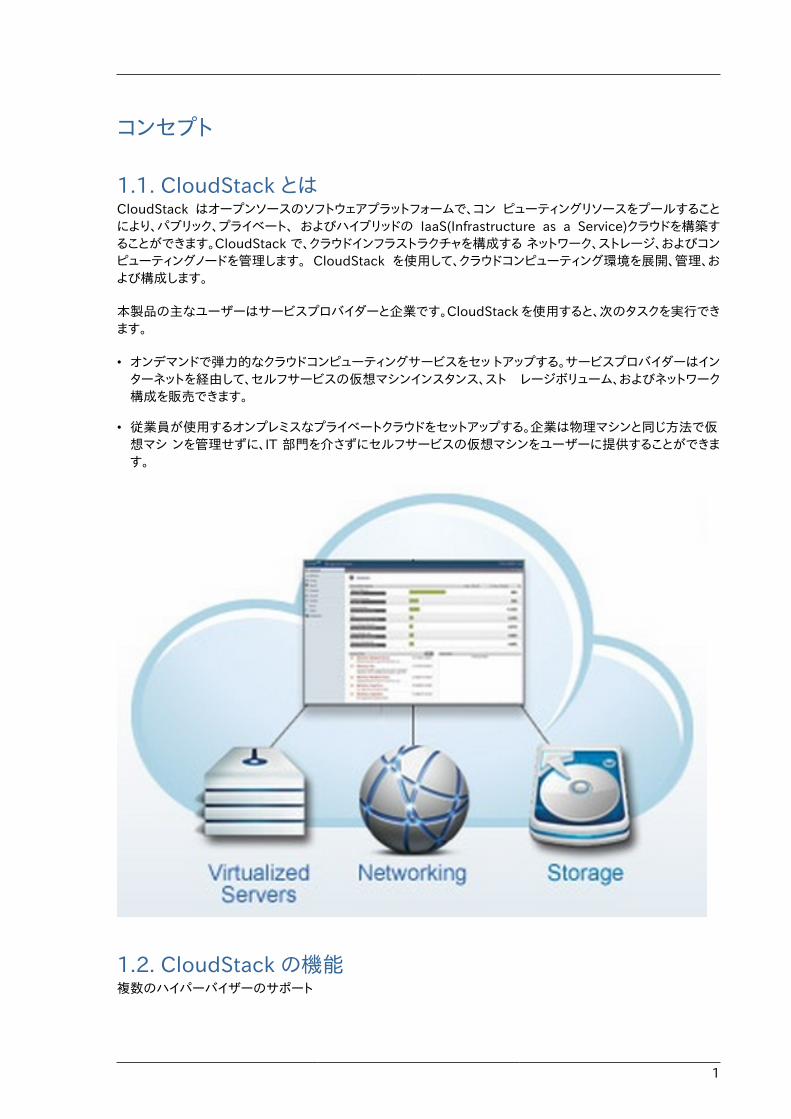
1.1. CloudStack とはCloudStack はオープンソースのソフトウェアプラットフォームで、コン ピューティングリソースをプールすることにより、パブリック、プライベート、 およびハイブリッドの IaaS(Infrastructure as a Service)クラウドを構築することができます。CloudStack で、クラウドインフラストラクチャを構成する ネットワーク、ストレージ、およびコンピューティングノードを管理します。 CloudStack を使用して、クラウドコンピューティング環境を展開、管理、および構成します。
本製品の主なユーザーはサービスプロバイダーと企業です。CloudStack を使用すると、次のタスクを実行できます。
• オンデマンドで弾力的なクラウドコンピューティングサービスをセッ トアップする。サービスプロバイダーはインターネットを経由して、セルフサービスの仮想マシンインスタンス、スト レージボリューム、およびネットワーク構成を販売できます。
• 従業員が使用するオンプレミスなプライベートクラウドをセットアップする。企業は物理マシンと同じ方法で仮想マシ ンを管理せずに、IT 部門を介さずにセルフサービスの仮想マシンをユーザーに提供することができます。
1.2. CloudStack の機能複数のハイパーバイザーのサポート
第1章 コンセプト
2
CloudStack はさまざまなハイパーバイザーと連動します。単一のクラウド環境に、ハイパーバイザーの実装を複数含められます。現在の CloudStack リリースでは、エンタープライズクラスのハイパーバイザーであるCitrix XenServer や VMware vSphere も CentOS, Ubuntu 上の KVM, Xen と同様にサポートされます。
高度にスケーラブルなインフラストラクチャ管理
CloudStack では、地理的に分散した複数のデータセンターに設置される、何万台ものサーバーを管理することが できます。集中型の管理サーバーを直線的に拡張できるので、中間のクラスターレベルの管理サーバーが不要 です。単一のコンポーネントに障害が発生しても、クラスターまたはクラウド全体が停止することはありません。ク ラウドで実行中の仮想マシンの機能に影響を与えずに、管理サーバーの定期保守を実行できます。
自動的な構成管理
CloudStack では、各ゲスト仮想マシンのネットワークとストレージの設定が自動的に構成されます。
CloudStack では、クラウド自体をサポートする仮想アプライアンスのプールが内部的に管理されます。これらのア プライアンスにより、ファイアウォール、ルーティング、DHCP、VPN アクセス、コンソールプロキシ、ストレージアク セス、およびストレージ複製などのサービスが提供されます。仮想アプライアンスを幅広く使用することによって、 クラウド環境のインストール、構成、および継続的な管理を大いに単純化します。
グラフィカルユーザーインターフェイス
CloudStack offers an administrator's Web interface, used for provisioning and managing the cloud,as well as an end-user's Web interface, used for running VMs and managing VM templates. The UIcan be customized to reflect the desired service provider or enterprise look and feel.
標準 API のサポート
CloudStack はユーザーインターフェイスで使用できるすべての管理機能にプログラムでアクセスするためのAPI を提供します。API は継続的に保守され、文書化されています。この API を使用すると、個々のニーズに合ったコマンドラインツールや新しいユーザーインターフェイスを作成できます。『Developer’s Guide』と『APIReference』を参照してください。それぞれ、 Apache CloudStack Guides1 と Apache CloudStack APIReference2 から参照できます。
CloudStack のプラッガブルなアロケーターのアーキテクチャはホストやストレージに対する新しいタイプの割り当てを許容しています。以下のアロケーター実装ガイドも参照して下さい。http://docs.cloudstack.org/CloudStack_Documentation/Allocator_Implementation_Guide
高可用性
CloudStack は可用性を高めるためシステムに幾つかの機能を持っています。管理サーバーを複数ノードにインストールし、サーバー間でロードバランシングをすることが出来ます。MySQLをデータベースの障害時に手動でフェイルオーバーするためレプリケーションの設定をすることも可能でしょう。ホストに対しては CloudStackはNICのボンディングやiSCSIのマルチパスのようにストレージ通信を分割することをサポートしています。
1.3. 展開アーキテクチャの概要CloudStack のインストールは、管理サーバーおよび管理サーバーで管理するクラウドインフラストラクチャの 2つの部分に分けられます。CloudStack クラウドのセットアップと管理においては、ホスト、ストレージデバイス、および IP アドレスのようなリソースを管理者が管理サーバーに準備し、管理サーバーがそれらのリソースを管理します。
1 http://cloudstack.apache.org/docs/en-US/index.html2 http://cloudstack.apache.org/docs/api/index.html
管理サーバーについて
3
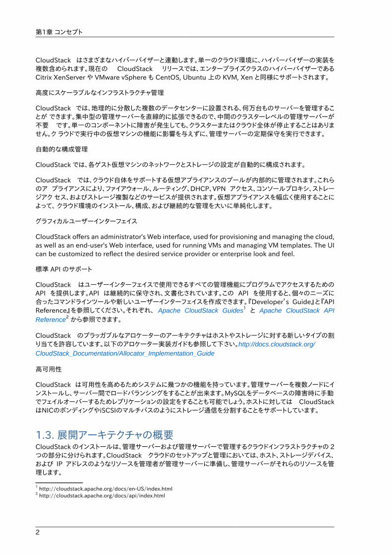
最小構成でインストールする場合は、CloudStack 管理サーバーを実行する 1 台のマシンとクラウドインフラストラクチャとして動作するもう 1 台のマシンをセットアップします。この場合のクラウドインフラストラクチャは非常に単純で、ハイパーバイザーソフトウェアを実行する 1 台のホストで構成されます。最小の展開では 1 台のマシン上で管理サーバーとハイパーバイザーホストの両方を担うことができます。(その場合、KVM ハイパーバイザーを利用します)
A more full-featured installation consists of a highly-available multi-node Management Serverinstallation and up to tens of thousands of hosts using any of several advanced networking setups.For information about deployment options, see the "Choosing a Deployment Architecture" sectionof the $PRODUCT; Installation Guide.
1.3.1. 管理サーバーについて管理サーバーは、クラウドリソースを管理する CloudStack ソフトウェアです。ユーザーインターフェイスまたはAPI を介して 管理サーバーを操作することにより、クラウドインフラストラクチャを構成し管理できます。
管理サーバーは専用のサーバーまたは仮想マシンです。ホストに対する仮想マシンの割り当てを制御し、ストレージと IP アドレスを仮想マシンインスタンスに割り当てます。CloudStack 管理サーバーは Tomcat コンテナー内で動作し、データ保 持のために MySQL データベースを必要とします。
このマシンは「4.3: 最小システム要件」にあるシステム要件を満たしている必要があります。
管理サーバー
• 管理者とエンドユーザーに Web ユーザーインターフェイスを提供します。
• CloudStack プラットフォームの API を提供します。
• 特定ホストに対するゲスト仮想マシンの割り当てを管理します。
• 特定アカウントに対するパブリックおよびプライベート IP アドレスの割り当てを管理します。
• ゲストに対する仮想ディスクとしてのストレージの割り当てを管理します。
• スナップショット、テンプレート、および ISO イメージを管理し、場合によっては複数のデータセンターの間でそれらを 複製します。
• クラウド構成のための単一の場を提供します。
第1章 コンセプト
4
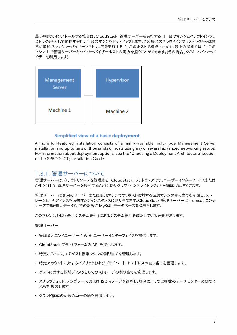
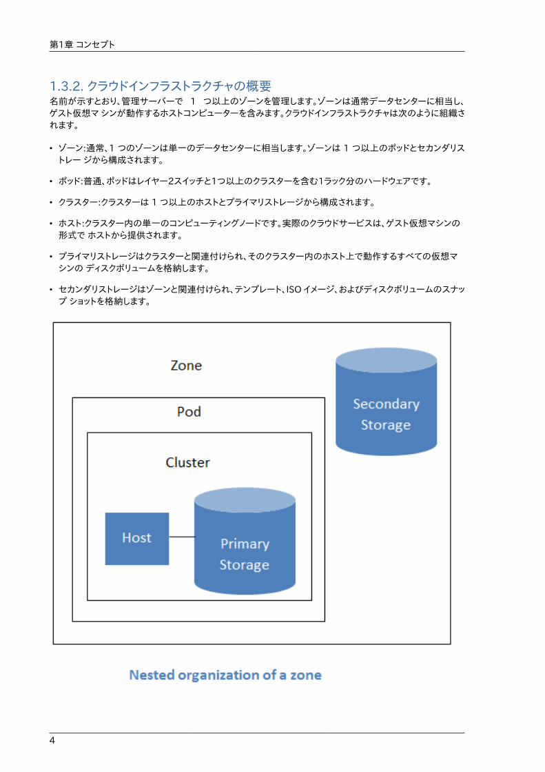
1.3.2. クラウドインフラストラクチャの概要名前が示すとおり、管理サーバーで 1 つ以上のゾーンを管理します。ゾーンは通常データセンターに相当し、ゲスト仮想マ シンが動作するホストコンピューターを含みます。クラウドインフラストラクチャは次のように組織されます。
• ゾーン:通常、1 つのゾーンは単一のデータセンターに相当します。ゾーンは 1 つ以上のポッドとセカンダリストレー ジから構成されます。
• ポッド:普通、ポッドはレイヤー2スイッチと1つ以上のクラスターを含む1ラック分のハードウェアです。
• クラスター:クラスターは 1 つ以上のホストとプライマリストレージから構成されます。
• ホスト:クラスター内の単一のコンピューティングノードです。実際のクラウドサービスは、ゲスト仮想マシンの形式で ホストから提供されます。
• プライマリストレージはクラスターと関連付けられ、そのクラスター内のホスト上で動作するすべての仮想マシンの ディスクボリュームを格納します。
• セカンダリストレージはゾーンと関連付けられ、テンプレート、ISO イメージ、およびディスクボリュームのスナップ ショットを格納します。
ネットワーク
5
詳細情報
より詳細な情報はドキュメントの「クラウドインフラストラクチャコンセプト」を参照してください。
1.3.3. ネットワークCloudStack では基本と拡張の 2 種類のネットワーク設定を提供します。
• 基本ネットワーク。 基本ネットワーク設定では、AWSスタイルのネットワークの単一共有ネットワークを提供します。セキュリティグループ(発信元 IP アドレスのフィルター) のようなレイヤー3 レベルの方法でゲストを分離できます。
• 拡張ネットワーク。拡張ネットワー ク設定は、より洗練されたネットワーク技術をサポートします。このネットワークモデルを選択すると、より柔軟にゲストの ネットワークを定義できます。
詳しくは、「ネットワークセットアップ」を参照してください。

6

7
クラウドインフラストラクチャのプロビジョニング
2.1. リージョンについてクラウドの信頼性を高めるために、複数の地理的に異なったリージョンにリソースを分けて配置することができます。\nリージョンは、 CloudStack を構成する要素の中で最も大きい単位です。\nリージョンは、データセンターとほぼ同意であるアベイラビリティゾーンにより構成されます。\nそれぞれのリージョンは、リージョン内の1つのゾーンにある管理サーバ群により管理されます。\nリージョン内の各ゾーンは、地理的に近い場所に配置します。\nリージョンは、フォールトトレランスとディザスタリカバリを実現する上で有効です。
ゾーンをリージョンとしてグループ化にすることにより、より高い可用性とスケーラビリティを実現することができます。\nユーザアカウントはリージョンをまたいで使用できるため、分散された複数のリージョンにVMを作成することができます。\nリージョンのいずれかが使用できなくなった場合でも、他のリージョンのVMを使ってサービスを継続することができます。\nまた、管理サーバから近いゾーンをグループ化することで、分散された複数のゾーンを1つの管理サーバ群で管理するのに比べ、クラウド内のレイテンシを軽減できます。
使用状況データもまたリージョンレベルでまとめることができ、リージョンごとのレポート情報が作成できます。
リージョン情報はエンドユーザからも参照できます。ユーザはゲストVMを作成する際、起動させるリージョンを選択する必要があります。ユーザはまた、選択したリージョン上でゲストVMを作成するためにプライベートテンプレートをコピーする処理が必要になるかもしれません。
2.2. ゾーンについてゾーンは CloudStack 環境内で2番目に大きい組織単位です。1 つのデータセンター内に複数のゾーンを持たせることはできますが、通常、ゾーンは単一のデータセンターに相当します。インフラストラクチャをゾーンに組織化すると、ゾーンを物理的に分離して冗長性を持たせることができます。たとえば、各ゾーンに電源とネットワークアップリンクを配備します。必須では ありませんが、ゾーンは遠隔地に分散することができます。
第2章 クラウドインフラストラクチャのプロビジョニング
8
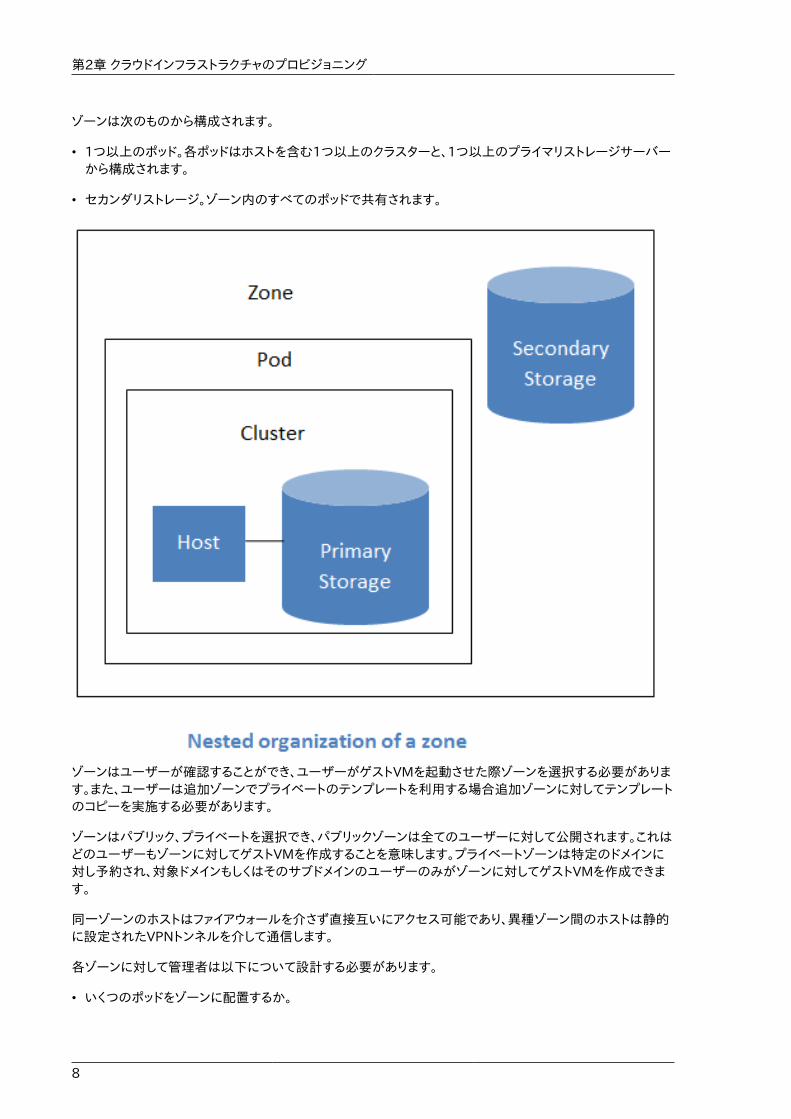
ゾーンは次のものから構成されます。
• 1つ以上のポッド。各ポッドはホストを含む1つ以上のクラスターと、1つ以上のプライマリストレージサーバーから構成されます。
• セカンダリストレージ。ゾーン内のすべてのポッドで共有されます。
ゾーンはユーザーが確認することができ、ユーザーがゲストVMを起動させた際ゾーンを選択する必要があります。また、ユーザーは追加ゾーンでプライベートのテンプレートを利用する場合追加ゾーンに対してテンプレートのコピーを実施する必要があります。
ゾーンはパブリック、プライベートを選択でき、パブリックゾーンは全てのユーザーに対して公開されます。これはどのユーザーもゾーンに対してゲストVMを作成することを意味します。プライベートゾーンは特定のドメインに対し予約され、対象ドメインもしくはそのサブドメインのユーザーのみがゾーンに対してゲストVMを作成できます。
同一ゾーンのホストはファイアウォールを介さず直接互いにアクセス可能であり、異種ゾーン間のホストは静的に設定されたVPNトンネルを介して通信します。
各ゾーンに対して管理者は以下について設計する必要があります。
• いくつのポッドをゾーンに配置するか。
ポッドについて
9
• いくつのクラスターを各ポッドに配置するか。
• いくつのホストを各クラスターに配置するか。
• いくつのプライマリストレージサーバーを各クラスターに配置し、総容量をどうするか。
• いくつのセカンダリストレージサーバーをゾーンに配置するか。
新しいゾーンを追加した際は、まずゾーンに対し物理ネットワークや第一のポッド、クラスター、ホスト、プライマリストレージ、セカンダリストレージを設定します。
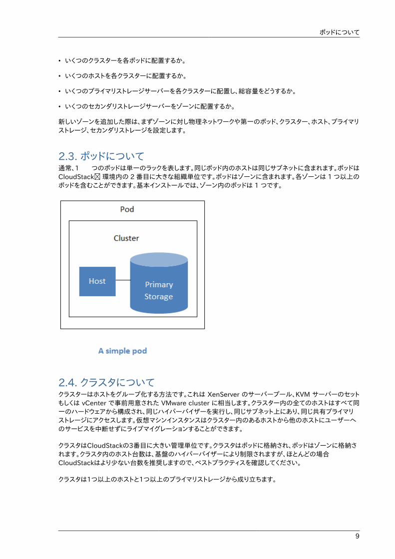
2.3. ポッドについて通常、1 つのポッドは単一のラックを表します。同じポッド内のホストは同じサブネットに含まれます。ポッドはCloudStack� 環境内の 2 番目に大きな組織単位です。ポッドはゾーンに含まれます。各ゾーンは 1 つ以上のポッドを含むことができます。基本インストールでは、ゾーン内のポッドは 1 つです。
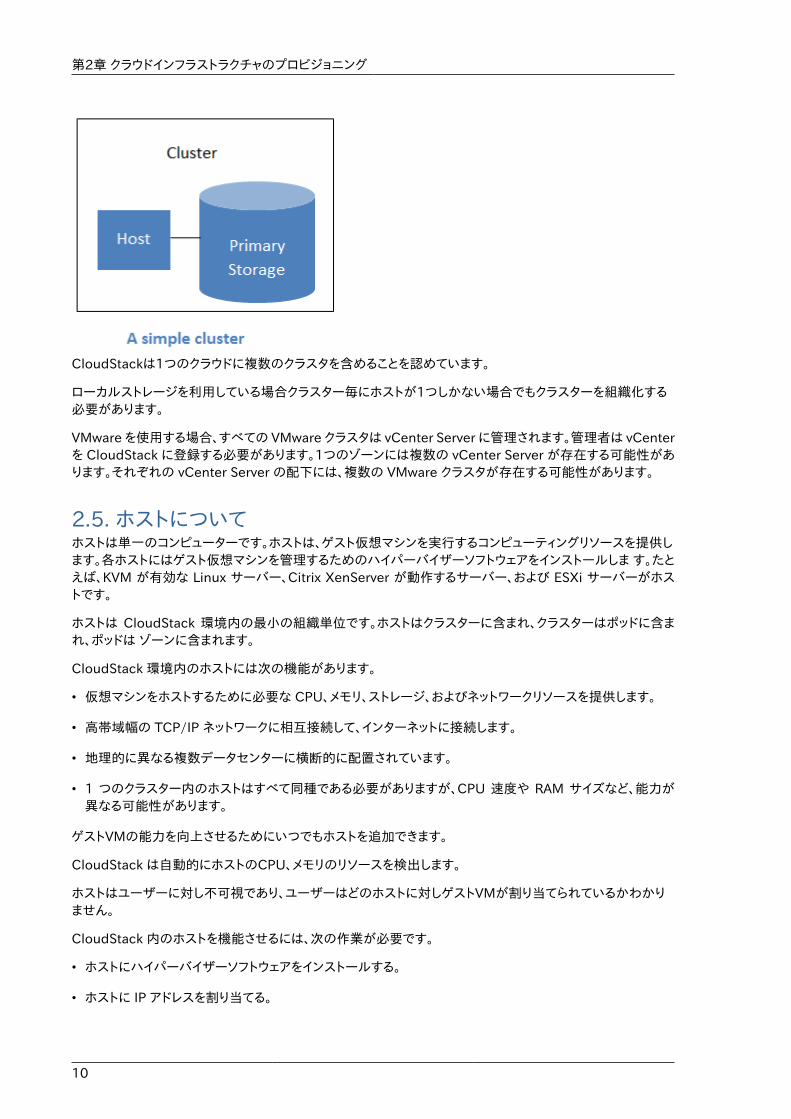
2.4. クラスタについてクラスターはホストをグループ化する方法です。これは XenServer のサーバープール、KVM サーバーのセットもしくは vCenter で事前用意された VMware cluster に相当します。クラスター内の全てのホストはすべて同一のハードウェアから構成され、同じハイパーバイザーを実行し、同じサブネット上にあり、同じ共有プライマリストレージにアクセスします。仮想マシンインスタンスはクラスター内のあるホストから他のホストにユーザーへのサービスを中断せずにライブマイグレーションすることができます。
クラスタはCloudStackの3番目に大きい管理単位です。クラスタはポッドに格納され、ポッドはゾーンに格納されます。クラスタ内のホスト台数は、基盤のハイパーバイザーにより制限されますが、ほとんどの場合CloudStackはより少ない台数を推奨しますので、ベストプラクティスを確認してください。
クラスタは1つ以上のホストと1つ以上のプライマリストレージから成り立ちます。
第2章 クラウドインフラストラクチャのプロビジョニング
10
CloudStackは1つのクラウドに複数のクラスタを含めることを認めています。
ローカルストレージを利用している場合クラスター毎にホストが1つしかない場合でもクラスターを組織化する必要があります。
VMware を使用する場合、すべての VMware クラスタは vCenter Server に管理されます。管理者は vCenterを CloudStack に登録する必要があります。1つのゾーンには複数の vCenter Server が存在する可能性があります。それぞれの vCenter Server の配下には、複数の VMware クラスタが存在する可能性があります。
2.5. ホストについてホストは単一のコンピューターです。ホストは、ゲスト仮想マシンを実行するコンピューティングリソースを提供します。各ホストにはゲスト仮想マシンを管理するためのハイパーバイザーソフトウェアをインストールしま す。たとえば、KVM が有効な Linux サーバー、Citrix XenServer が動作するサーバー、および ESXi サーバーがホストです。
ホストは CloudStack 環境内の最小の組織単位です。ホストはクラスターに含まれ、クラスターはポッドに含まれ、ポッドは ゾーンに含まれます。
CloudStack 環境内のホストには次の機能があります。
• 仮想マシンをホストするために必要な CPU、メモリ、ストレージ、およびネットワークリソースを提供します。
• 高帯域幅の TCP/IP ネットワークに相互接続して、インターネットに接続します。
• 地理的に異なる複数データセンターに横断的に配置されています。
• 1 つのクラスター内のホストはすべて同種である必要がありますが、CPU 速度や RAM サイズなど、能力が異なる可能性があります。
ゲストVMの能力を向上させるためにいつでもホストを追加できます。
CloudStack は自動的にホストのCPU、メモリのリソースを検出します。
ホストはユーザーに対し不可視であり、ユーザーはどのホストに対しゲストVMが割り当てられているかわかりません。
CloudStack 内のホストを機能させるには、次の作業が必要です。
• ホストにハイパーバイザーソフトウェアをインストールする。
• ホストに IP アドレスを割り当てる。
プライマリストレージについて
11
• ホストが CloudStack 管理サーバーに接続していることを確認する。
2.6. プライマリストレージについてプライマリストレージはクラスターと関連付けられ、そのクラスター内のホスト上で動作するすべての仮想マシンのディスクボリュームを格納します。複数のプライマリストレージをクラスターに追加することができ、少なくとも1つのプライマリストレージが必要です。通常はパフォーマンス向上のため、ホストの近くに配置します。
CloudStack は利用するハイパーバイザーでサポートされている全ての標準規格に沿ったiSCSI、NFSに対応するよう設計されています。それは次にしめすデバイスを含みます。
• Dell EqualLogic� for iSCSI
• Network Appliances filers for NFS and iSCSI
• Scale Computing for NFS
もし、ローカルディスクのみを使ってインストールを進める場合、次のセカンダリストレージにスキップすることができます。
2.7. セカンダリストレージについてセカンダリストレージはゾーンと関連付けられ、次の項目を格納します。
• テンプレート – 仮想マシンの起動に使用できるオペレーティングシステムイメージで、アプリケーションのインストー ルなど追加の構成を含めることができます。
• ISO イメージ – データまたはオペレーティングシステムの起動可能なメディアを含むディスクイメージです。
• ディスクボリュームのスナップショット – 仮想マシンデータの保存コピーです。データの復元または新しいテンプ\nレートの作成に使用できます。
セカンダリストレージ内の項目は、ゾーン内のすべてのホストで使用できます。CloudStack は特定のプライマリストレージデバイスに対するゲストVMの仮想ディスクを管理します。
セカンダリストレージ内の項目をクラウドを介して全てのホストで利用可能にするには OpenStack オブジェクトストレージ(Swift, swift.openstack.org1) をセカンダリストレージに追加することができます。Swiftを使う場合、Swiftストレージを CloudStack 全体で構成します。通常通りセカンダリストレージを各ゾーンで設定すると、各ゾーンのセカンダリストレージは全てのテンプレートや他のセカンダリストレージのデータをSwiftに中継します。Swiftストレージはクラウド全体に渡るリソースとして動作し、作成されたテンプレートやその他のデータがクラウド上のあらゆるゾーンから利用可能になります。Swiftストレージは階層的な構造ではなく、ストレージオブジェクト毎に単一のSwiftコンテナーが用意されます。クラウド上の全てのセカンダリストレージは必要に応じSwiftからコンテナーを取得します。その際、あるゾーンから他のゾーンに対してテンプレートやスナップショットをコピーする必要はなく、単一のNFSのように扱うことができ、全てのデータはあらゆる場所から利用可能になります。
2.8. 物理ネットワークについてゾーン追加時に物理ネットワークを設定します。拡張ゾーンにおいて1つもしくは複数の物理ネットワークを各ゾーン関連付けることができます。これはホストのハイパーバイザーにおけるNICに相当し、各物理ネットワークは1つもしくは複数のネットワークのトラフィックタイプを転送します。各ネットワークに対するトラフィックタイプの選択はゾーン作成時に基本ネットワーク、拡張ネットワークのどちらを選択したかに強く依存します。
1 http://swift.openstack.org
第2章 クラウドインフラストラクチャのプロビジョニング
12
物理ネットワークはゾーンにおけるネットワークハードウェアやケーブルの配線に相当し、複数の物理ネットワークを持たせることができます。管理者は次のようなことができます。
• ゾーン内の物理ネットワークの追加/削除/更新
• 物理ネットワークのVLAN設定
• ハイパーバイザーからネットワークを認識するための名前の設定
• 物理ネットワーク上で利用可能なサービスプロバイダーの設定(ファイアウォール、ロードバランサー等)
• 物理ネットワークに渡すIPアドレスの設定
• 物理ネットワークで流れるトラフィックタイプの指定
2.8.1. 基本ゾーンのネットワークトラフィックの種類基本ネットワーク設定を使用する場合は、ゾーンで使用できる物理ネットワークは 1 つだけです。その物理ネットワークでは、次の 3 種類のトラ フィックが伝送されます。
• ゲスト : エンドユーザーが仮想マシンを実行すると、ゲストトラフィックが生成されます。ゲスト仮想マシンは、ゲストネットワークと呼ばれるネットワークを介して互いに通信します。基本ゾーンの各ポッドはブロードキャストドメイン なので、ゲストネットワークに対してそれぞれ異なる IP アドレス範囲を持ちます。管理者は、各ポッドの IP アドレス 範囲を構成する必要があります。
• Management. When CloudStack's internal resources communicate with each other, theygenerate management traffic. This includes communication between hosts, system VMs (VMsused by CloudStack to perform various tasks in the cloud), and any other component thatcommunicates directly with the CloudStack Management Server. You must configure the IP rangefor the system VMs to use.
注記�管理トラフィックとゲストトラフィックに別々の NIC を使用することを強くお勧めします。
• パブリック : パブリックトラフィックはクラウド上の仮想マシンがインターネットにアクセスする際に生成されます。これには外部からアクセス可能な IP が割り当てられなければいけません。「新規 IP アドレスの取得」に記述されているようにエンドユーザーはこれらの IP を CloudStack ユーザーインターフェースから取得しゲストネットワークとパブリックネットワーク間の NAT を実現できます。
• Storage. While labeled "storage" this is specifically about secondary storage, and doesn't affecttraffic for primary storage. This includes traffic such as VM templates and snapshots, whichis sent between the secondary storage VM and secondary storage servers. CloudStack uses aseparate Network Interface Controller (NIC) named storage NIC for storage network traffic. Useof a storage NIC that always operates on a high bandwidth network allows fast template andsnapshot copying. You must configure the IP range to use for the storage network.
基本ネットワークの場合は、物理ネットワークの構成はごく簡単です。多くの場合、’構成する必要があるのはゲスト仮想マシンが生成するトラフィックを伝送するための 1 つのゲストネットワークだけです。もしNetScalerロードバランサーを用い、エラスティック IP や エラスティックロードバランサー(EIP, ELB) 機能を利用する場合はパブリックトラフィックを転送するためのネットワークを設定しなければなりません。CloudStack ではユーザーインターフェースから新しいゾーンを追加する際に必要なネットワーク設定に注意を払う必要があります。

基本ゾーンのゲスト IP アドレス
13
2.8.2. 基本ゾーンのゲスト IP アドレス基本ネットワーク設定を使用する場合は、CloudStack はポッドの CIDR の IP アドレスをそのポッドのゲストに割り当てます。 管理者は、そのためにポッドの直接 IP アドレスの範囲を追加する必要があります。これらの IP アドレスはホストと同じ VLAN に含まれます。
2.8.3. 拡張ゾーンのネットワークトラフィックの種類拡張ネットワーク設定を使用する場合は、ゾーンで複数の物理ネットワークを使用できます。各物理ネットワークで 1 つまたは複数の種類のトラフィックを伝送できます。各ネットワークで伝送するネットワークトラフィックの種類を、CloudStack に 識別させる必要があります。拡張ゾーンのトラフィックには次の種類があります。
• ゲスト : エンドユーザーが仮想マシンを実行すると、ゲストトラフィックが生成されます。ゲスト仮想マシンは、ゲストネットワークと呼ばれるネットワークを介して互いに通信します。このネットワークは、分離することも共有すること もできます。分離されたゲストネットワークの場合は、管理者は各 CloudStack アカウントのネットワークを分離するための VLAN 範囲を予約する必要があります(多数の VLAN が必要になる可能性があります)。共有されたゲ ストネットワークでは、すべてのゲスト仮想マシンが 1 つのネットワークを共有します。この場合は、セキュリティグループなどのレイヤー3 のネットワーク分離技術を使用して分離を提供できます。
• 管理 : CloudStack の内部リソースが互いに通信すると、管理トラフィックが生成されます。これには、ホスト、シス テム仮想マシン(クラウド内のさまざまなタスクを実行するために CloudStack によって使用される仮想マシン)、および CloudStack 管理サーバーと直接通信するほかのコンポーネントの間の通信が含まれます。使用するシステム仮想マシンの IP 範囲を構成する必要があります。
• パブリック : パブリックトラフィックは、クラウド内の仮想マシンがインターネットにアクセスすると生成されます。このために、パブリックにアクセスできる IP アドレスを割り当てる必要があります。エンドユーザーは、「新規IP アドレスの取得」にあるように CloudStack ユーザーインターフェイスを使用してそれらの IP アドレスを取得して、ゲストネットワークとパブリックネットワークの間に NAT を実装できます。
• Storage. While labeled "storage" this is specifically about secondary storage, and doesn't affecttraffic for primary storage. This includes traffic such as VM templates and snapshots, whichis sent between the secondary storage VM and secondary storage servers. CloudStack uses aseparate Network Interface Controller (NIC) named storage NIC for storage network traffic. Useof a storage NIC that always operates on a high bandwidth network allows fast template andsnapshot copying. You must configure the IP range to use for the storage network.
これらのトラフィックは、それぞれ異なる物理ネットワークで伝送することも、一定の制限の下に同じ物理ネットワークで伝送することもできます。ユーザーインターフェイスでゾーンの追加ウィザードを使用して新しいゾーンを作成すると、有効な選択肢のみが提示されます。
2.8.4. 拡張ゾーンのゲスト IP アドレス拡張ネットワーク設定を使用する場合は、ゲストが使用するための追加のネットワークを作成できます。それらのネットワークは、ゾーン全体を対象にしてすべてのアカウントが使用できるようにすることも、単一のアカウントを対象にすること もできます。後者の場合、それらのネットワークに接続するゲストを作成できるのはそのアカウントだけになります。ネットワークは、VLAN ID、IP アドレス範囲、およびゲートウェイによって定義されます。管理者は、こうしたネットワークを必要に応じて何千もプロビジョニングできます。
2.8.5. 拡張ゾーンのパブリック IP アドレス拡張ネットワーク設定を使用する場合は、ゲストが使用するための追加のネットワークを作成できます。それらのネットワークは、ゾーン全体を対象にしてすべてのアカウントが使用できるようにすることも、単一のアカウントを対象にすること もできます。後者の場合、それらのネットワークに接続するゲストを作成できるのはそのアカウ
第2章 クラウドインフラストラクチャのプロビジョニング
14
ントだけになります。ネットワークは、VLAN ID、IP アドレス範囲、およびゲートウェイによって定義されます。管理者は、こうしたネットワークを必要に応じて何千もプロビジョニングできます。
2.8.6. システムにより予約済みの IP アドレス各ゾーンで、管理ネットワーク用に予約済みの IP アドレスの範囲を構成する必要があります。このネットワークは、CloudStack 管理サーバーとさまざまなシステム仮想マシン(セカンダリストレージ仮想マシン、コンソールプロキシ仮想マシン、DHCP など)の間の通信に使用されます。
予約済みの IP アドレスは、クラウド全体で一意である必要があります。たとえば、2 つのゾーンのホストに同じプライベート IP アドレスを使用することはできません。
ポッド内のホストにはプライベート IP アドレスが割り当てられます。これは通常、RFC1918 アドレスです。コンソールプロキシとセカンダリストレージのシステム仮想マシンにも、それらが作成されたポッドの CIDR のプライベート IP アドレスが割り当てられます。
コンピューティングサーバーと管理サーバーはシステム予約 IP 範囲外の IP アドレスを利用します。例として、システム予約 IP 範囲が 192.168.154.2 から始まり 192.168.154.7 で終わる場合、CloudStack は .2 から .7をシステム仮想マシンに利用できます。 これはポッドの CIDR とは別になり .8 から .254 を管理サーバーやハイパーバイザーホストに利用できます。
全てのゾーンで :
各ポッドのシステムにプライベート IP アドレスを割り当てて、CloudStack で準備します。
KVM と XenServer で推奨されるポッドあたりのプライベート IP アドレスの数は、ホストごとに 1 つです。ポッドの拡張が予想される場合は、拡張に対応できるだけの数のプライベート IP アドレスをあらかじめ追加しておきます。
拡張ネットワーク設定を使用するゾーンで :
For zones with advanced networking, we recommend provisioning enough private IPs for yourtotal number of customers, plus enough for the required CloudStack System VMs. Typically, about10 additional IPs are required for the System VMs. For more information about System VMs, seeWorking with System Virtual Machines in the Administrator's Guide.
拡張ネットワーク設定を使用する場合は、各ポッドで使用できるプライベート IP アドレスの数は、そのポッドのノードで実行するハイパーバイザーによって異なります。Citrix XenServer と KVM ではリンクローカルアドレスが使用されるため、理論上は、アドレスブロック内で 65,000 を超える数のプライベート IP アドレスを使用できます。次第にポッドが拡張されても、ホ ストやゲスト仮想ルーターの IP アドレスが足りなくなることはまずありません。一方、VMWare ESXi では、管理者が指定するサブネット方式が使用されるため、一般的なポッドあたりの IP アドレスの数は 255 個のみです。これらのアドレスは、物理マシン、ゲスト仮想ルーター、およびそのほかのエンティティに割り当てられるため、ノードで ESXi が実行されているポッ ドを拡張するときには、プライベート IP アドレスが足りなくなる可能性があります。
拡張ネットワーク設定を使用する ESXi ポッドでプライベート IP 領域を拡張するための適切な余裕を確保するには、次のどちらか、または両方の方法を使用します。
• サブネットに対してより大きい CIDR ブロックを指定する。サフィックスが/20 のサブネットマスクでは、4,000個を超える IP アドレスを提供できます。
• 複数のポッドを、それぞれ独自のサブネットを指定して作成する。たとえば、10 個のポッドを作成し、各ポッドに 255 個の IP を持たせる場合、2,550 個の IP アドレスを提供できます。
15
インストール
3.1. 対象の読者クラウドの設計フェーズや、精巧な展開計画を経験した人、あるいはトライアルの規模を拡大する準備ができている人。以下の手順では、VLANを使った拡張ネットワーク、高可用性、ロードバランサーやファイアウォールなどの外部機器との連携、Citrix XenServer、KVM、VMware vSphereなどマルチハイパーバイザーのサポートなど、CloudStackのさらに高度な機能を利用できます。
3.2. インストール手順の概要簡単な試用インストール以上のことを行うには、構成のさまざまな選択肢についてガイダンスが必要になります。次の項目を参照することを強くお勧めします。
• 展開アーキテクチャの選択
• ハイパーバイザーの選択 : サポートされる機能
• ネットワークのセットアップ
• ストレージのセットアップ
• ベストプラクティス
1. 必要なハードウェアの準備ができたかどうかの確認。���������� を参照してください。
2. 管理サーバーのインストール(単一ノードか複数ノードかを選択します)。��������������� を参照してください。
3. ユーザーインターフェイスへのログイン。4������������� を参照してください。
4. ゾーンの追加。最初のポッド、クラスター、およびホストの設定。�������� を参照してください。
5. ポッドの追加(オプション)。�������� を参照してください。
6. クラスターの追加(オプション)。��������� を参照してください。
7. ホストの追加(オプション)。�������� を参照してください。
8. プライマリストレージの追加(オプション)。��������������� を参照してください。
9. セカンダリストレージの追加(オプション)。��������������� を参照してください。
10. クラウドの使用。��������� を参照してください。
3.3. 最小システム要件
3.3.1. 管理サーバー, データベースとストレージシステムの要件管理サーバーとMySQLデータベースを動作させるため以下の要件を満たすサーバー。同一サーバー上でローカルディスクやNFSを利用してプライマリストレージ、セカンダリストレージを提供することも可能です。管理サーバーは仮想マシン上で動作させることもできます。
• オペレーティングシステム:
第3章 インストール
16
• 推奨: CentOS/RHEL 6.3以上、もしくは Ubuntu 12.04(.1)
• 64-bit x86 CPU(多くのコアを用意することでパフォーマンスの向上が見込まれます)
• 4GBのメモリ
• 250GB以上のストレージ(多くの実績から500GB以上を推奨)。
• 最少1つ以上のNIC
• 静的に割り当てられたIPアドレス
• hostnameコマンドで完全修飾ホスト名が返される
3.3.2. ホスト/ハイパーバイザーの要件ゲストVMを構成するクラウドサービスを動作させるホスト。各ホストは一つの物理筐体であり、次の要件を満たす必要があります。
• ハードウェア仮想マシン(Intel-VTまたはAMD-Vが有効であること)をサポートする必要がありま す。
• 64-bit x86 CPU(多くのコアを用意することでパフォーマンスの向上が見込まれます)
• 完全仮想化のサポートが必要。
• 4GBのメモリ
• 36 GBのローカルディスク
• 最少1つ以上のNIC
•注記もし、ホストに対し DHCP を利用する場合、DHCP サーバーがこれらホストに配布する IPとCloudStack によって作成された仮想ルーターの DHCP が競合しないことを確認してください。
• 最新のホットフィックスが適用されたハイパーバイザー。
• CloudStack が展開された際、ハイパーバイザーホストに既に動作しているVMが存在していない。
• クラスター内にあるホストは全て同スペックでなければいけません。CPU の種類や数、機能フラグが同じでなければいけません。
ホストはハイパーバイザーに依存した追加要件を満たす必要があります。インストールの章の上部にある要件リストからあなたの選択したハイパーバイザーを確認してください。
警告加えてハイパーバイザーの要件とガイドに記述されているインストール手順を満たす必要があります。ハイパーバイザーホストは CloudStack と連携する出来るよう適切に準備しなければなります。例として XenServerの要件を以下のCitrix XenServer インストールに記述します。
リポジトリの設定
17
• �KVM �����������
• �XenServer�����������
• �vSphere �����������
3.4. リポジトリの設定CloudStack は、公式ミラーサイトからソースの形でのみ提供されます。しかしながら、CloudStackのコミュニティメンバーがバイナリを提供してくれると思うので、ユーザはソースからビルドする事なくApacheCloudStackをインストールできるでしょう。
If you didn't follow the steps to build your own packages from source in the sections for �BuildingRPMs from Source� or �DEB���������� you may find pre-built DEB and RPM packages for yourconvenience linked from the downloads1 page.
注記これらのリポジトリには管理サーバとKVMハイパーバイザーのパッケージが含まれます。
3.4.1. DEBパッケージのリポジトリ次のコマンドで、apt sources にDEBパッケージのリポジトリ情報を追加できます。現時点では、Ubuntu 12.04LTS (precise) 用のパッケージのみ用意されています。
好きなエディタで /etc/apt/sources.list.d/cloudstack.list を開いて(または作成して)下さい。コミュニティが提供するレポジトリ情報をファイルに追加します。
deb http://cloudstack.apt-get.eu/ubuntu precise 4.0
公開鍵をtrustedキーに追加します。
$ wget -O - http://cloudstack.apt-get.eu/release.asc|apt-key add -
ローカルのaptキャッシュを更新します。
$ apt-get update
DEBパッケージリポジトリが設定され、使用できるようになりました。
3.4.2. RPM package repositoryThere is a RPM package repository for CloudStack so you can easily install on RHEL based platforms.
If you're using an RPM-based system, you'll want to add the Yum repository so that you can installCloudStack with Yum.
Yum repository information is found under /etc/yum.repos.d. You'll see several .repo files in thisdirectory, each one denoting a specific repository.
1 http://cloudstack.apache.org/downloads.html
第3章 インストール
18
To add the CloudStack repository, create /etc/yum.repos.d/cloudstack.repo and insert thefollowing information.
[cloudstack]name=cloudstackbaseurl=http://cloudstack.apt-get.eu/rhel/4.0/enabled=1gpgcheck=0
Now you should be able to install CloudStack using Yum.
3.5. 管理サーバーのインストール
3.5.1. 管理サーバーのインストールここでは管理サーバーのインストール手順について説明します。インストールには2種類の手順があり、あなたのクラウド環境にいくつの管理サーバーを用意するかによって異なります。
• 単一ホストでの管理サーバーと MySQL。
• 物理的に分けられた複数ホストへの管理サーバーと MySQL。
どちらの場合でもこれらのマシンは「システム要件」に記載されているシステム要件を満たしている必要 があります。
警告セキュリティのため、パブリックインターネット から管理サーバー上のポート 8096 または8250 にアクセスできないようにする必要があります。
管理サーバーインストールの手順:
1. オペレーティングシステムの準備
2. (XenServer のみ) vhd-util をダウンロードしてインストールしてください。
3. 最初の管理サーバーのインストール
4. MySQLのインストールと設定
5. NFS共有の準備
6. 追加の管理サーバーの準備と起動(オプション)
7. システム仮想マシンテンプレートの準備
3.5.2. オペレーティングシステムの準備管理サーバーをホストするために、次の手順に従ってオペレーティングシステムを準備する必要があります。これらの手 順は各管理サーバーノードで実行する必要があります。
1. オペレーティングシステムにルートユーザーとしてログオンします。
初期ホストへの管理サーバーのインストール
19
2. 完全修飾ホスト名を確認します。
hostname --fqdn
This should return a fully qualified hostname such as "management1.lab.example.org". If it doesnot, edit /etc/hosts so that it does.
3. 管理サーバーからインターネットに接続できることを確認します。
ping www.cloudstack.org
4. 時刻を同期するために NTP を有効にします。
注記クラウドのサーバーのクロックを同期するた めに NTP が必要です。
a. NTPのインストール
yum install ntp
apt-get install openntpd
5. これらの手順を管理サーバーがインストールされた全てのホストで実行します。
3.5.3. 初期ホストへの管理サーバーのインストール最初のインストールでは管理サーバーのインストールを単一か複数ホストに対して行うかに関わらず単一ホストに対してのソフトウェアインストールを行います。
注記もし高可用性のため管理サーバーを複数ノードにインストール場合ホストの追加は実施せずこの後のステップを完了してから行なってください。
CloudStack 管理サーバーは RPM か DEB パッケージを利用してインストールできます。これらのパッケージは管理サーバーを動かすために必要な全てを含んでいます。
3.5.3.1. CentOS/RHEL でのインストールまず、必要なパッケージをインストールします。
yum install cloud-client
3.5.3.2. Ubuntu でのインストール
apt-get install cloud-client
第3章 インストール
20
3.5.3.3. vhd-util をダウンロードします。次の手順はハイパーバイザーホストとして XenServer をインストールした場合のみ必要となります。
管理サーバーをセットアップする前に、vhd-util2 から vhd-util をダウンロードしてください。
管理サーバーに RHEL もしくは CentOS を利用している場合は vhd-util を /usr/lib64/cloud/common/scripts/vm/hypervisor/xenserver にコピーしてください。
管理サーバーに Ubuntu を利用している場合は vhd-util を /usr/lib/cloud/common/scripts/vm/hypervisor/xenserver にコピーしてください。
3.5.4. Install the database serverThe CloudStack management server uses a MySQL database server to store its data. When you areinstalling the management server on a single node, you can install the MySQL server locally. Foran installation that has multiple management server nodes, we assume the MySQL database alsoruns on a separate node.
CloudStack has been tested with MySQL 5.1 and 5.5. These versions are included in RHEL/CentOSand Ubuntu.
3.5.4.1. 管理サーバーノード上でのデータベースインストールこの章では管理サーバーと同一のノードにどのように MySQL をインストールするかを説明しています。これは単一の管理サーバーノードの展開を想定しています。もし、複数ノードへの管理サーバーの展開を実施している場合、一般的には MySQL 用に別ノードを用意します。詳細は �Install the Database on a Separate Node� を参照して下さい。
1. Install MySQL from the package repository of your distribution:
yum install mysql-server
apt-get install mysql-server
2. Open the MySQL configuration file. The configuration file is /etc/my.cnf or /etc/mysql/my.cnf,depending on your OS.
3. Insert the following lines in the [mysqld] section.
You can put these lines below the datadir line. The max_connections parameter should beset to 350 multiplied by the number of Management Servers you are deploying. This exampleassumes one Management Server.
注記On Ubuntu, you can also create a file /etc/mysql/conf.d/cloudstack.cnf andadd these directives there. Don't forget to add [mysqld] on the first line of thefile.
innodb_rollback_on_timeout=1
2 http://download.cloud.com.s3.amazonaws.com/tools/vhd-util
Install the database server
21
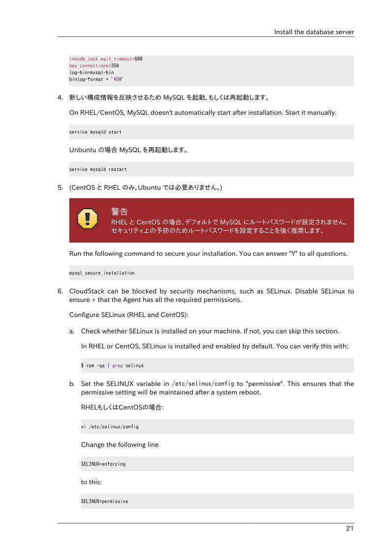
innodb_lock_wait_timeout=600max_connections=350log-bin=mysql-binbinlog-format = 'ROW'
4. 新しい構成情報を反映させるため MySQL を起動、もしくは再起動します。
On RHEL/CentOS, MySQL doesn't automatically start after installation. Start it manually.
service mysqld start
Unbuntu の場合 MySQL を再起動します。
service mysqld restart
5. (CentOS と RHEL のみ。Ubuntu では必要ありません。)
警告RHEL と CentOS の場合、デフォルトで MySQL にルートパスワードが設定されません。セキュリティ上の予防のためルートパスワードを設定することを強く推奨します。
Run the following command to secure your installation. You can answer "Y" to all questions.
mysql_secure_installation
6. CloudStack can be blocked by security mechanisms, such as SELinux. Disable SELinux toensure + that the Agent has all the required permissions.
Configure SELinux (RHEL and CentOS):
a. Check whether SELinux is installed on your machine. If not, you can skip this section.
In RHEL or CentOS, SELinux is installed and enabled by default. You can verify this with:
$ rpm -qa | grep selinux
b. Set the SELINUX variable in /etc/selinux/config to "permissive". This ensures that thepermissive setting will be maintained after a system reboot.
RHELもしくはCentOSの場合:
vi /etc/selinux/config
Change the following line
SELINUX=enforcing
to this:
SELINUX=permissive
第3章 インストール
22
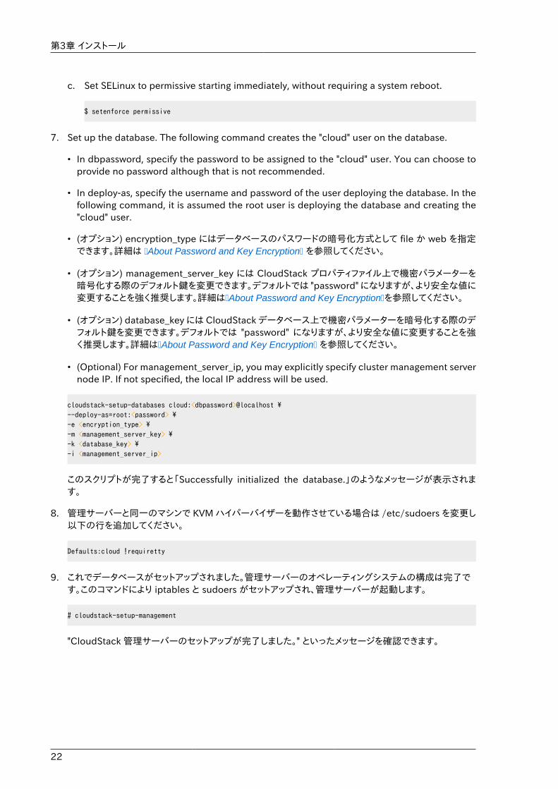
c. Set SELinux to permissive starting immediately, without requiring a system reboot.
$ setenforce permissive
7. Set up the database. The following command creates the "cloud" user on the database.
• In dbpassword, specify the password to be assigned to the "cloud" user. You can choose toprovide no password although that is not recommended.
• In deploy-as, specify the username and password of the user deploying the database. In thefollowing command, it is assumed the root user is deploying the database and creating the"cloud" user.
• (オプション) encryption_type にはデータベースのパスワードの暗号化方式として file か web を指定できます。詳細は �About Password and Key Encryption� を参照してください。
• (オプション) management_server_key には CloudStack プロパティファイル上で機密パラメーターを暗号化する際のデフォルト鍵を変更できます。デフォルトでは "password" になりますが、より安全な値に変更することを強く推奨します。詳細は�About Password and Key Encryption�を参照してください。
• (オプション) database_key には CloudStack データベース上で機密パラメーターを暗号化する際のデフォルト鍵を変更できます。デフォルトでは "password" になりますが、より安全な値に変更することを強く推奨します。詳細は�About Password and Key Encryption� を参照してください。
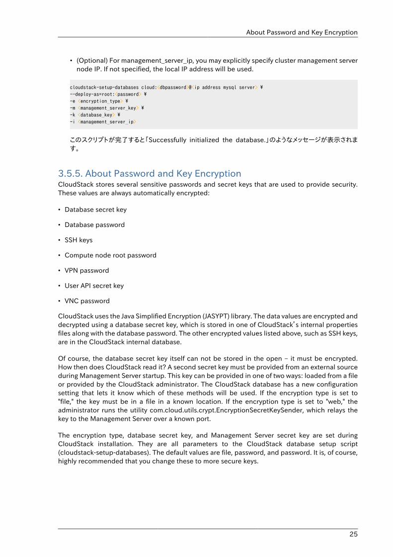
• (Optional) For management_server_ip, you may explicitly specify cluster management servernode IP. If not specified, the local IP address will be used.
cloudstack-setup-databases cloud:<dbpassword>@localhost \--deploy-as=root:<password> \-e <encryption_type> \-m <management_server_key> \-k <database_key> \-i <management_server_ip>
このスクリプトが完了すると「Successfully initialized the database.」のようなメッセージが表示されます。
8. 管理サーバーと同一のマシンで KVM ハイパーバイザーを動作させている場合は /etc/sudoers を変更し以下の行を追加してください。
Defaults:cloud !requiretty
9. これでデータベースがセットアップされました。管理サーバーのオペレーティングシステムの構成は完了です。このコマンドにより iptables と sudoers がセットアップされ、管理サーバーが起動します。
# cloudstack-setup-management
"CloudStack 管理サーバーのセットアップが完了しました。" といったメッセージを確認できます。
Install the database server
23
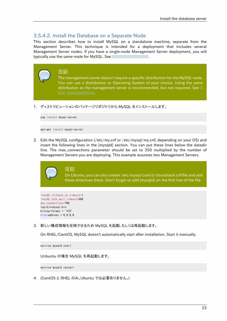
3.5.4.2. Install the Database on a Separate NodeThis section describes how to install MySQL on a standalone machine, separate from theManagement Server. This technique is intended for a deployment that includes severalManagement Server nodes. If you have a single-node Management Server deployment, you willtypically use the same node for MySQL. See ��������������������������.
注記The management server doesn't require a specific distribution for the MySQL node.You can use a distribution or Operating System of your choice. Using the samedistribution as the management server is recommended, but not required. See �������, ��������������������.
1. ディストリビューションのパッケージリポジトリから MySQL をインストールします。
yum install mysql-server
apt-get install mysql-server
2. Edit the MySQL configuration (/etc/my.cnf or /etc/mysql/my.cnf, depending on your OS) andinsert the following lines in the [mysqld] section. You can put these lines below the datadirline. The max_connections parameter should be set to 350 multiplied by the number ofManagement Servers you are deploying. This example assumes two Management Servers.
注記On Ubuntu, you can also create /etc/mysql/conf.d/cloudstack.cnf file and addthese directives there. Don't forget to add [mysqld] on the first line of the file.
innodb_rollback_on_timeout=1innodb_lock_wait_timeout=600max_connections=700log-bin=mysql-binbinlog-format = 'ROW'bind-address = 0.0.0.0
3. 新しい構成情報を反映させるため MySQL を起動、もしくは再起動します。
On RHEL/CentOS, MySQL doesn't automatically start after installation. Start it manually.
service mysqld start
Unbuntu の場合 MySQL を再起動します。
service mysqld restart
4. (CentOS と RHEL のみ。Ubuntu では必要ありません。)
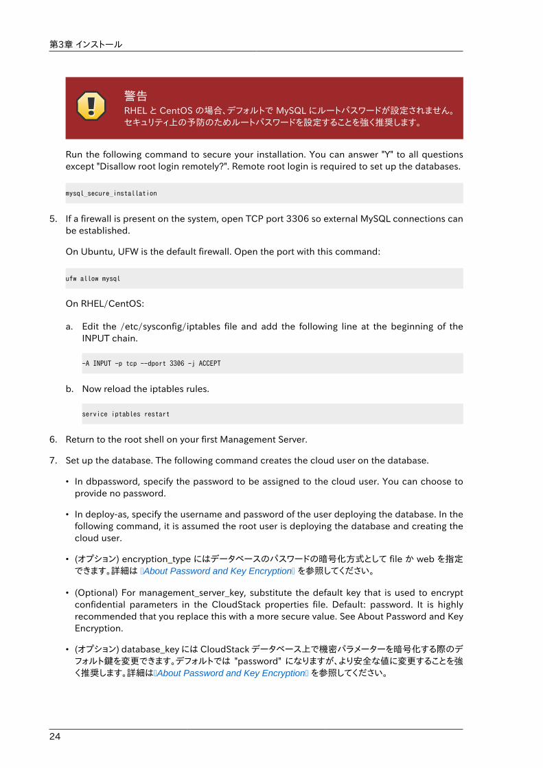
第3章 インストール
24
警告RHEL と CentOS の場合、デフォルトで MySQL にルートパスワードが設定されません。セキュリティ上の予防のためルートパスワードを設定することを強く推奨します。
Run the following command to secure your installation. You can answer "Y" to all questionsexcept "Disallow root login remotely?". Remote root login is required to set up the databases.
mysql_secure_installation
5. If a firewall is present on the system, open TCP port 3306 so external MySQL connections canbe established.
On Ubuntu, UFW is the default firewall. Open the port with this command:
ufw allow mysql
On RHEL/CentOS:
a. Edit the /etc/sysconfig/iptables file and add the following line at the beginning of theINPUT chain.
-A INPUT -p tcp --dport 3306 -j ACCEPT
b. Now reload the iptables rules.
service iptables restart
6. Return to the root shell on your first Management Server.
7. Set up the database. The following command creates the cloud user on the database.
• In dbpassword, specify the password to be assigned to the cloud user. You can choose toprovide no password.
• In deploy-as, specify the username and password of the user deploying the database. In thefollowing command, it is assumed the root user is deploying the database and creating thecloud user.
• (オプション) encryption_type にはデータベースのパスワードの暗号化方式として file か web を指定できます。詳細は �About Password and Key Encryption� を参照してください。
• (Optional) For management_server_key, substitute the default key that is used to encryptconfidential parameters in the CloudStack properties file. Default: password. It is highlyrecommended that you replace this with a more secure value. See About Password and KeyEncryption.
• (オプション) database_key には CloudStack データベース上で機密パラメーターを暗号化する際のデフォルト鍵を変更できます。デフォルトでは "password" になりますが、より安全な値に変更することを強く推奨します。詳細は�About Password and Key Encryption� を参照してください。
About Password and Key Encryption
25
• (Optional) For management_server_ip, you may explicitly specify cluster management servernode IP. If not specified, the local IP address will be used.
cloudstack-setup-databases cloud:<dbpassword>@<ip address mysql server> \--deploy-as=root:<password> \-e <encryption_type> \-m <management_server_key> \-k <database_key> \-i <management_server_ip>
このスクリプトが完了すると「Successfully initialized the database.」のようなメッセージが表示されます。
3.5.5. About Password and Key EncryptionCloudStack stores several sensitive passwords and secret keys that are used to provide security.These values are always automatically encrypted:
• Database secret key
• Database password
• SSH keys
• Compute node root password
• VPN password
• User API secret key
• VNC password
CloudStack uses the Java Simplified Encryption (JASYPT) library. The data values are encrypted anddecrypted using a database secret key, which is stored in one of CloudStack’s internal propertiesfiles along with the database password. The other encrypted values listed above, such as SSH keys,are in the CloudStack internal database.
Of course, the database secret key itself can not be stored in the open – it must be encrypted.How then does CloudStack read it? A second secret key must be provided from an external sourceduring Management Server startup. This key can be provided in one of two ways: loaded from a fileor provided by the CloudStack administrator. The CloudStack database has a new configurationsetting that lets it know which of these methods will be used. If the encryption type is set to"file," the key must be in a file in a known location. If the encryption type is set to "web," theadministrator runs the utility com.cloud.utils.crypt.EncryptionSecretKeySender, which relays thekey to the Management Server over a known port.
The encryption type, database secret key, and Management Server secret key are set duringCloudStack installation. They are all parameters to the CloudStack database setup script(cloudstack-setup-databases). The default values are file, password, and password. It is, of course,highly recommended that you change these to more secure keys.
第3章 インストール
26
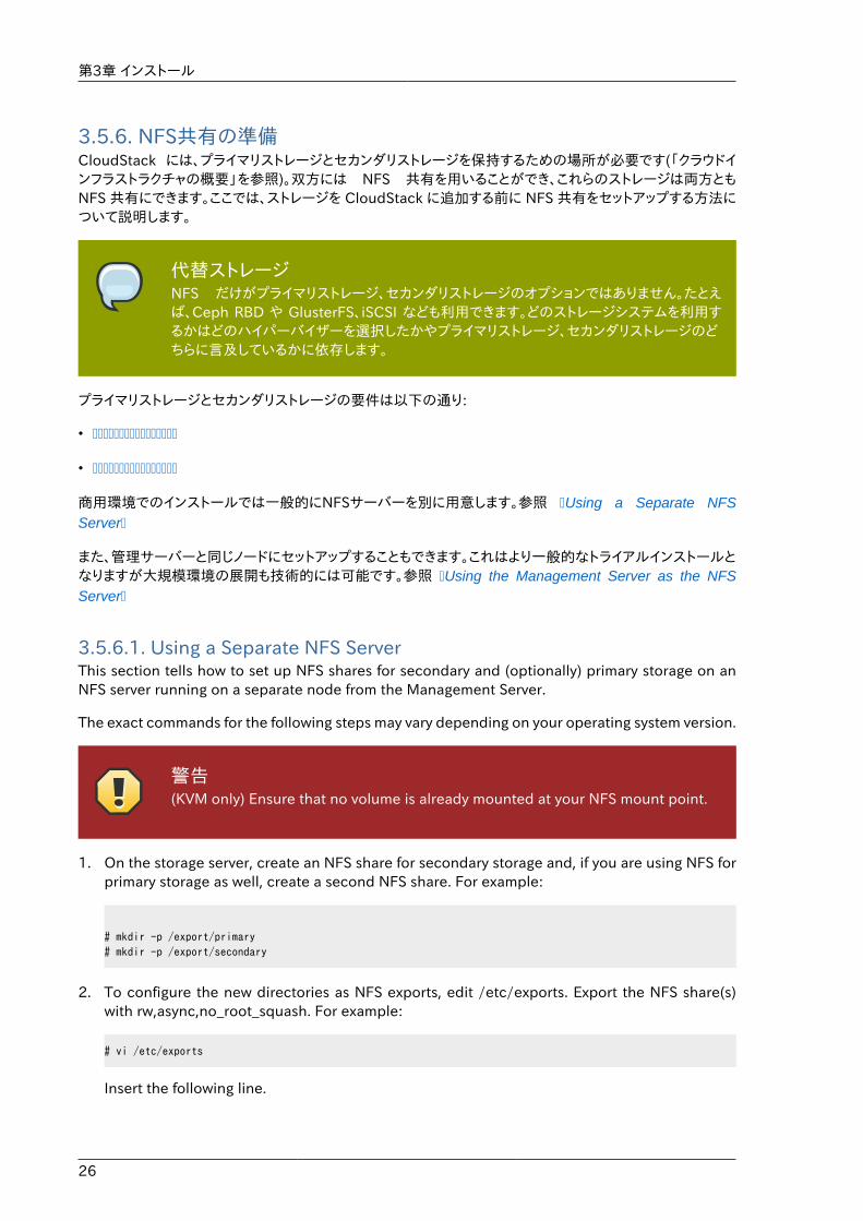
3.5.6. NFS共有の準備CloudStack には、プライマリストレージとセカンダリストレージを保持するための場所が必要です(「クラウドインフラストラクチャの概要」を参照)。双方には NFS 共有を用いることができ、これらのストレージは両方ともNFS 共有にできます。ここでは、ストレージを CloudStack に追加する前に NFS 共有をセットアップする方法について説明します。
代替ストレージNFS だけがプライマリストレージ、セカンダリストレージのオプションではありません。たとえば、Ceph RBD や GlusterFS、iSCSI なども利用できます。どのストレージシステムを利用するかはどのハイパーバイザーを選択したかやプライマリストレージ、セカンダリストレージのどちらに言及しているかに依存します。
プライマリストレージとセカンダリストレージの要件は以下の通り:
• ����������������
• ����������������
商用環境でのインストールでは一般的にNFSサーバーを別に用意します。参照 �Using a Separate NFSServer�
また、管理サーバーと同じノードにセットアップすることもできます。これはより一般的なトライアルインストールとなりますが大規模環境の展開も技術的には可能です。参照 �Using the Management Server as the NFSServer�
3.5.6.1. Using a Separate NFS ServerThis section tells how to set up NFS shares for secondary and (optionally) primary storage on anNFS server running on a separate node from the Management Server.
The exact commands for the following steps may vary depending on your operating system version.
警告(KVM only) Ensure that no volume is already mounted at your NFS mount point.
1. On the storage server, create an NFS share for secondary storage and, if you are using NFS forprimary storage as well, create a second NFS share. For example:
# mkdir -p /export/primary# mkdir -p /export/secondary
2. To configure the new directories as NFS exports, edit /etc/exports. Export the NFS share(s)with rw,async,no_root_squash. For example:
# vi /etc/exports
Insert the following line.
NFS共有の準備
27
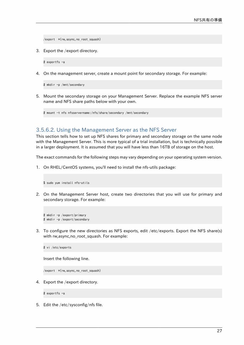
/export *(rw,async,no_root_squash)
3. Export the /export directory.
# exportfs -a
4. On the management server, create a mount point for secondary storage. For example:
# mkdir -p /mnt/secondary
5. Mount the secondary storage on your Management Server. Replace the example NFS servername and NFS share paths below with your own.
# mount -t nfs nfsservername:/nfs/share/secondary /mnt/secondary
3.5.6.2. Using the Management Server as the NFS ServerThis section tells how to set up NFS shares for primary and secondary storage on the same nodewith the Management Server. This is more typical of a trial installation, but is technically possiblein a larger deployment. It is assumed that you will have less than 16TB of storage on the host.
The exact commands for the following steps may vary depending on your operating system version.
1. On RHEL/CentOS systems, you'll need to install the nfs-utils package:
$ sudo yum install nfs-utils
2. On the Management Server host, create two directories that you will use for primary andsecondary storage. For example:
# mkdir -p /export/primary# mkdir -p /export/secondary
3. To configure the new directories as NFS exports, edit /etc/exports. Export the NFS share(s)with rw,async,no_root_squash. For example:
# vi /etc/exports
Insert the following line.
/export *(rw,async,no_root_squash)
4. Export the /export directory.
# exportfs -a
5. Edit the /etc/sysconfig/nfs file.
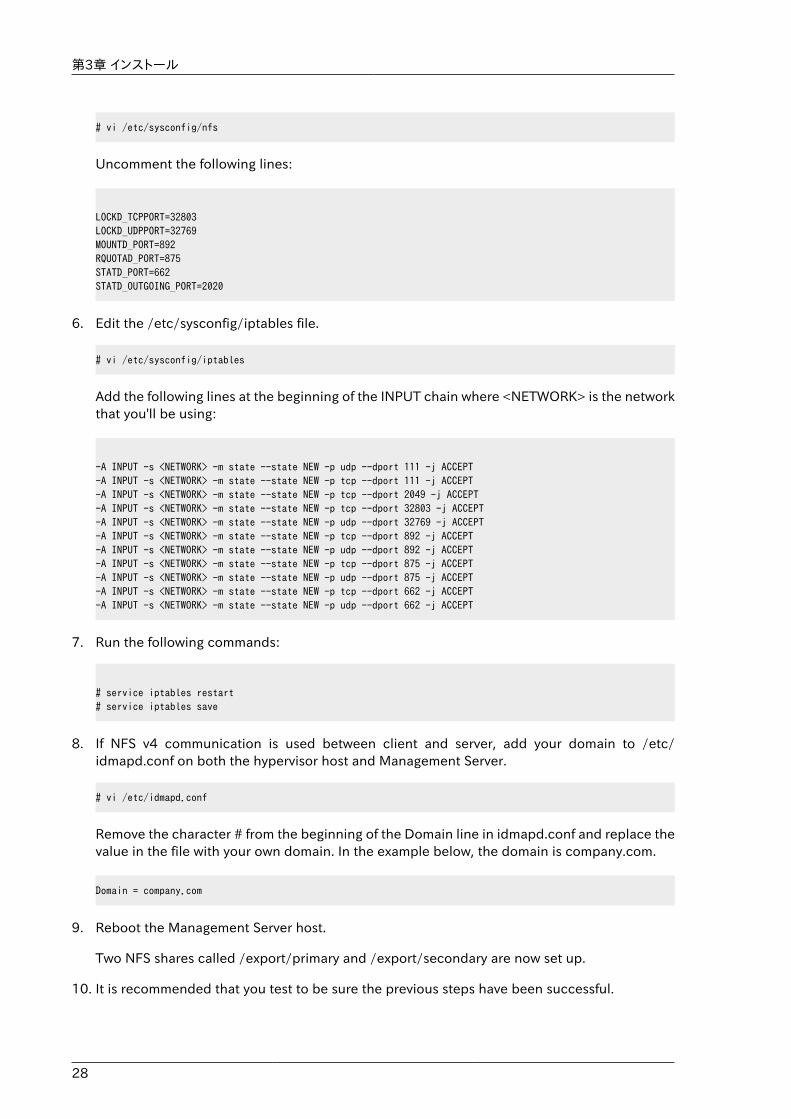
第3章 インストール
28
# vi /etc/sysconfig/nfs
Uncomment the following lines:
LOCKD_TCPPORT=32803LOCKD_UDPPORT=32769MOUNTD_PORT=892RQUOTAD_PORT=875STATD_PORT=662STATD_OUTGOING_PORT=2020
6. Edit the /etc/sysconfig/iptables file.
# vi /etc/sysconfig/iptables
Add the following lines at the beginning of the INPUT chain where <NETWORK> is the networkthat you'll be using:
-A INPUT -s <NETWORK> -m state --state NEW -p udp --dport 111 -j ACCEPT-A INPUT -s <NETWORK> -m state --state NEW -p tcp --dport 111 -j ACCEPT-A INPUT -s <NETWORK> -m state --state NEW -p tcp --dport 2049 -j ACCEPT-A INPUT -s <NETWORK> -m state --state NEW -p tcp --dport 32803 -j ACCEPT-A INPUT -s <NETWORK> -m state --state NEW -p udp --dport 32769 -j ACCEPT-A INPUT -s <NETWORK> -m state --state NEW -p tcp --dport 892 -j ACCEPT-A INPUT -s <NETWORK> -m state --state NEW -p udp --dport 892 -j ACCEPT-A INPUT -s <NETWORK> -m state --state NEW -p tcp --dport 875 -j ACCEPT-A INPUT -s <NETWORK> -m state --state NEW -p udp --dport 875 -j ACCEPT-A INPUT -s <NETWORK> -m state --state NEW -p tcp --dport 662 -j ACCEPT-A INPUT -s <NETWORK> -m state --state NEW -p udp --dport 662 -j ACCEPT
7. Run the following commands:
# service iptables restart# service iptables save
8. If NFS v4 communication is used between client and server, add your domain to /etc/idmapd.conf on both the hypervisor host and Management Server.
# vi /etc/idmapd.conf
Remove the character # from the beginning of the Domain line in idmapd.conf and replace thevalue in the file with your own domain. In the example below, the domain is company.com.
Domain = company.com
9. Reboot the Management Server host.
Two NFS shares called /export/primary and /export/secondary are now set up.
10. It is recommended that you test to be sure the previous steps have been successful.
追加の管理サーバーの準備と起動
29
a. Log in to the hypervisor host.
b. Be sure NFS and rpcbind are running. The commands might be different depending onyour OS. For example:
# service rpcbind start# service nfs start# chkconfig nfs on# chkconfig rpcbind on# reboot
c. Log back in to the hypervisor host and try to mount the /export directories. For example(substitute your own management server name):
# mkdir /primarymount# mount -t nfs <management-server-name>:/export/primary /primarymount# umount /primarymount# mkdir /secondarymount# mount -t nfs <management-server-name>:/export/secondary /secondarymount# umount /secondarymount
3.5.7. 追加の管理サーバーの準備と起動2 台目以降の管理サーバーについて、管理サーバーのソフトウェアをインストールしてデータベースに接続し、管理サーバーのオペレーティングシステムをセットアップします。
1. ����������������� と �Building RPMs from Source� もしくは �DEB���������� の手順を必要に応じて実施します。
2. ハイパーバイザーホストとして XenServer をインストールしている場合は次の手順が必要となります。
vhd-util3 から vhd-utl をダウンロードします。
管理サーバーに RHEL や CentOS を利用している場合は vhd-utl を /usr/lib64/cloud/common/scripts/vm/hypervisor/xenserver にコピーしてください。
管理サーバーに Ubuntu を利用している場合は vhd-util を /usr/lib/cloud/common/scripts/vm/hypervisor/xenserver/vhd-util にコピーしてください。
3. 必要なサービスが起動中であり起動時に開始するよう設定されていることを確認します。
# service rpcbind start# service nfs start# chkconfig nfs on# chkconfig rpcbind on
4. データベースクライアントを構成します。このケースでは --deploy-as オプションが付与されていないことに注意してください。(このコマンドの引数に関する詳細は �Install the Database on a Separate Node� を参照してください)。
# cloudstack-setup-databases cloud:dbpassword@dbhost -e encryption_type -m management_server_key -k database_key -i management_server_ip
第3章 インストール
30
5. オペレーティングシステムを構成し、管理サーバーを起動します。
# cloudstack-setup-management
このノード上の管理サーバーが起動します。
6. これらの手順をそれぞれの追加する管理サーバー上で実行します。
7. 管理サーバー用の負荷分散装置を構成します。�Management Server Load Balancing� を参照してください。
3.5.8. システム仮想マシンテンプレートの準備CloudStack システム仮想マシンに使用するテンプレートをセカンダリス トレージに配置する必要があります。
注記コマンドをコピーして実行するときは、単一の行として貼り付けたことを確認してください。 一部のドキュメントビューアーでは、コピーしたテキストに不要な改行が含まれる可能性があります。
1. 管理サーバーで次の cloud-install-sys-tmplt コマンドを実 行して、システム仮想マシンテンプレートを取得して展開します。 このゾーンでエンドユーザーが実行することが予想される各ハイパーバイザーの種類に対応するコマンドを実行します。
セカンダリストレージのマウントポイントが/mnt/secondary でない場合は、実際のマウントポイント名に置き換えま す。
If you set the CloudStack database encryption type to "web" when you set up the database,you must now add the parameter -s <management-server-secret-key>. See �About Passwordand Key Encryption�.
この処理を実行するにはローカルファイルシステムに約 5 GB の空き領域が必要で、実行するたびに最長で 30 分かかります。
• XenServer:
# /usr/share/cloudstack-common/scripts/storage/secondary/cloud-install-sys-tmplt -m /mnt/secondary -u http://download.cloud.com/templates/acton/acton-systemvm-02062012.vhd.bz2 -h xenserver -s <optional-management-server-secret-key> -F
• vSphere:
# /usr/share/cloudstack-common/scripts/storage/secondary/cloud-install-sys-tmplt -m /mnt/secondary -u http://download.cloud.com/templates/burbank/burbank-systemvm-08012012.ova -h vmware -s <optional-management-server-secret-key> -F
• KVM:
# /usr/share/cloudstack-common/scripts/storage/secondary/cloud-install-sys-tmplt -m /mnt/secondary -u http://download.cloud.com/templates/acton/acton-systemvm-02062012.qcow2.bz2 -h kvm -s <optional-management-server-secret-key> -F
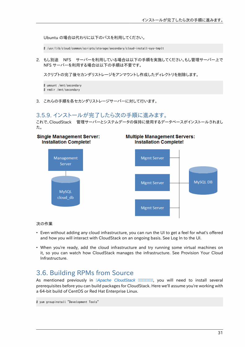
インストールが完了したら次の手順に進みます。
31
Ubuntu の場合は代わりに以下のパスを利用してください。
# /usr/lib/cloud/common/scripts/storage/secondary/cloud-install-sys-tmplt
2. もし別途 NFS サーバーを利用している場合は以下の手順を実施してください。もし管理サーバー上でNFS サーバーを利用する場合は以下の手順は不要です。
スクリプトの完了後セカンダリストレージをアンマウントし作成したディレクトリを削除します。
# umount /mnt/secondary# rmdir /mnt/secondary
3. これらの手順を各セカンダリストレージサーバーに対して行います。
3.5.9. インストールが完了したら次の手順に進みます。これで、CloudStack 管理サーバーとシステムデータの保持に使用するデータベースがインストールされました。
次の作業
• Even without adding any cloud infrastructure, you can run the UI to get a feel for what's offeredand how you will interact with CloudStack on an ongoing basis. See Log In to the UI.
• When you're ready, add the cloud infrastructure and try running some virtual machines onit, so you can watch how CloudStack manages the infrastructure. See Provision Your CloudInfrastructure.
3.6. Building RPMs from SourceAs mentioned previously in �Apache CloudStack ����������, you will need to install severalprerequisites before you can build packages for CloudStack. Here we'll assume you're working witha 64-bit build of CentOS or Red Hat Enterprise Linux.
# yum groupinstall "Development Tools"
第3章 インストール
32
# yum install java-1.6.0-openjdk-devel.x86_64 genisoimage mysql mysql-server ws-commons-util MySQL-python tomcat6 createrepo
Next, you'll need to install build-time dependencies for CloudStack with Maven. We're using Maven3, so you'll want to grab a Maven 3 tarball4 and uncompress it in your home directory (or whateverlocation you prefer):
$ tar zxvf apache-maven-3.0.4-bin.tar.gz
$ export PATH=/usr/local/apache-maven-3.0.4//bin:$PATH
Maven also needs to know where Java is, and expects the JAVA_HOME environment variable tobe set:
$ export JAVA_HOME=/usr/lib/jvm/jre-1.6.0-openjdk.x86_64/
Verify that Maven is installed correctly:
$ mvn --version
You probably want to ensure that your environment variables will survive a logout/reboot. Be sureto update ~/.bashrc with the PATH and JAVA_HOME variables.
Building RPMs for $PRODUCT; is fairly simple. Assuming you already have the source downloadedand have uncompressed the tarball into a local directory, you're going to be able to generatepackages in just a few minutes.
Packaging has ChangedIf you've created packages for $PRODUCT; previously, you should be aware thatthe process has changed considerably since the project has moved to usingApache Maven. Please be sure to follow the steps in this section closely.
3.6.1. Generating RPMSNow that we have the prerequisites and source, you will cd to the packaging/centos63/ directory.
Generating RPMs is done using the package.sh script:
$./package.sh
That will run for a bit and then place the finished packages in dist/rpmbuild/RPMS/x86_64/.
You should see six RPMs in that directory:
• cloudstack-agent-4.1.0.el6.x86_64.rpm
• cloudstack-awsapi-4.1.0.el6.x86_64.rpm
• cloudstack-cli-4.1.0.el6.x86_64.rpm
4 http://maven.apache.org/download.cgi
DEBパッケージのビルド
33
• cloudstack-common-4.1.0.el6.x86_64.rpm
• cloudstack-management-4.1.0.el6.x86_64.rpm
• cloudstack-usage-4.1.0.el6.x86_64.rpm
Filename VariationsThe file names may vary slightly. For instance, if you were to build the RPMs on aFedora 18 system, you'd see "fc18" instead of "el6" in the filename. (Fedora 18 isn'ta supported platform at this time, just providing an example.)
3.6.1.1. Creating a yum repoWhile RPMs is a useful packaging format - it's most easily consumed from Yum repositories over anetwork. The next step is to create a Yum Repo with the finished packages:
$ mkdir -p ~/tmp/repo
$ cp dist/rpmbuild/RPMS/x86_64/*rpm ~/tmp/repo/
$ createrepo ~/tmp/repo
The files and directories within ~/tmp/repo can now be uploaded to a web server and serve as ayum repository.
3.6.1.2. Configuring your systems to use your new yum repositoryNow that your yum repository is populated with RPMs and metadata we need to configure themachines that need to install $PRODUCT;. Create a file named /etc/yum.repos.d/cloudstack.repowith this information:
[apache-cloudstack] name=Apache CloudStack baseurl=http://webserver.tld/path/to/repo enabled=1 gpgcheck=0
Completing this step will allow you to easily install $PRODUCT; on a number of machines acrossthe network.
3.7. DEBパッケージのビルドIn addition to the bootstrap dependencies, you'll also need to install several other dependencies.Note that we recommend using Maven 3, which is not currently available in 12.04.1 LTS. So, you'llalso need to add a PPA repository that includes Maven 3. After running the command add-apt-repository, you will be prompted to continue and a GPG key will be added.
$ sudo apt-get update $ sudo apt-get install python-software-properties
第3章 インストール
34
$ sudo add-apt-repository ppa:natecarlson/maven3 $ sudo apt-get update $ sudo apt-get install ant debhelper openjdk-6-jdk tomcat6 libws-commons-util-java genisoimage python-mysqldb libcommons-codec-java libcommons-httpclient-java liblog4j1.2-java maven3
Now that we have resolved the dependencies we can move on to building CloudStack andpackaging them into DEBs.
mvn clean install -P developer,systemvm $ dpkg-buildpackge -uc -us
This command will build seven Debian packages. You should have the following:
• cloudstack-agent_4.1.0_all.deb
• cloudstack-awsapi_4.1.0_all.deb
• cloudstack-cli_4.1.0_all.deb
• cloudstack-common_4.1.0_all.deb
• cloudstack-docs_4.1.0_all.deb
• cloudstack-management_4.1.0_all.deb
• cloudstack-usage_4.1.0_all.deb
3.7.1. APTリポジトリの設定After you've created the packages, you'll want to copy them to a system where you can serve thepackages over HTTP. You'll create a directory for the packages and then use dpkg-scanpackagesto create Packages.gz, which holds information about the archive structure. Finally, you'll add therepository to your system(s) so you can install the packages using APT.
The first step is to make sure that you have the dpkg-dev package installed. This should havebeen installed when you pulled in the debhelper application previously, but if you're generatingPackages.gz on a different system, be sure that it's installed there as well.
$ sudo apt-get install dpkg-dev
The next step is to copy the DEBs to the directory where they can be served over HTTP. We'll use/var/www/cloudstack/repo in the examples, but change the directory to whatever works for you.
sudo mkdir -p /var/www/cloudstack/repo/binary sudo cp *.deb /var/www/cloudstack/repo/binary sudo cd /var/www/cloudstack/repo/binary sudo dpkg-scanpackages . /dev/null | tee Packages | gzip -9 > Packages.gz
注記: 上書きファイルファイルが存在しない旨のメッセージが表示されますが、ここでは無視して下さい。
APTリポジトリの設定
35
全てのDEBパッケージと Packages.gz は、HTTPサーバの binary ディレクトリに配置されているべきです。(次の手順に進む前に、wget または curl コマンドでファイルがダウンロードできることを確認して下さい。)
3.7.2. APTリポジトリの設定以上でリポジトリの作成は完了したので、マシン上に設定を追加してリポジトリを参照できるようにする必要があります。 /etc/apt/sources.list.d 配下にレポジトリの情報を追加することで実現できます。好きなエディタで以下の行を含むファイル /etc/apt/sources.list.d/cloudstack.list を作成してください。
deb http://server.url/cloudstack/repo binary ./
Now that you have the repository info in place, you'll want to run another update so that APT knowswhere to find the CloudStack packages.
$ sudo apt-get update
以上で、Ubuntuにインストールする手順に進むことができます。
3.8. Apache CloudStack の構築に必要なものCloudStack を構築する上で、用意すべきものがいくつかあります。このドキュメントではRPMまたはDEBパッケージを使うLinuxシステムについて説明します。
CloudStack をコンパイルするためには最低限以下が必要となります。1. Maven (version 3)
2. Java (OpenJDK 1.6 or Java 7/OpenJDK 1.7)
3. Apache Web Services Common Utilities (ws-commons-util)
4. MySQL
5. MySQLdb (provides Python database API)
6. Tomcat 6 (not 6.0.35)
7. genisoimage
8. rpmbuild or dpkg-dev

36
37
ユーザーインターフェイス
4.1. UIへのログインCloudStack はWebベースのUIを管理者とエンドユーザーの両方に提供しています。ログインに使用したユーザーの権限に応じて適切なUIが表示されます。UIはIE7、IE8、IE9、Firefox 3.5以降、Firefox 4、Safari 4 そしてSafari 5に対応しています。URLは(あなたの環境の管理サーバーのIPアドレスに置き換えてください)
http://<management-server-ip-address>:8080/client
未設定の管理サーバーにアクセスすると、ガイドツアーのスプラッシュスクリーンが表示されます。以降のアクセス時には、ダッシュボードにアクセスするために下記の情報を入力するログイン画面が表示されます。
ユーザー名あなたのアカウントのユーザーID。デフォルトのユーザー名はadminです。
パスワードユーザーIDに関連付けられたパスワード。デフォルトユーザーのパスワードはpasswordです。
ドメインもしもあなたがrootドメインのユーザーならば、フィールドは空白のままにします。
もしもあなたがサブドメインのユーザーならば、rootドメインを除いた、そのドメインへのフルパスを入力します。
例えばrootドメインの下にComp1/hrといった複数階層があると仮定します。Comp1ドメインのユーザーはドメインフィールドにComp1と入力し、Comp1/salesドメインのユーザーはComp1/salesと入力します。
より詳細なUIへのログインのガイドラインに関しては「ルート管理者としてのログイン」を参照してください。
4.1.1. End User's UI OverviewCloudStack ユーザーインターフェイスはユーザーのクラウドインフラストラクチャにおいて閲覧や仮想マシン、テンプレートと ISO、データボリュームとスナップショット、ゲストネットワーク、IP アドレスなどのクラウドリソースの利用を手助けします。もしユーザーが1つ以上の CloudStack プロジェクトのメンバーもしくは管理者である場合、ユーザーインターフェイスはプロジェクト向けのビューを提供します。
4.1.2. Root Administrator's UI OverviewCloudStack UI は CloudStack 管理者のプロビジョニングや確認、クラウドインフラストラクチャやドメイン、ユーザーアカウント、プロジェクト、構成設定の管理を手助けします。初回の管理サーバーのインストール時、クラウドインフラストラクチャのプロビジョニングのため、次のガイドツアーを利用できます。ログイン後、ユーザー毎のダッシュボードが表示され、様々なリンクや、様々な管理者機能へのナビゲーションバーが左側に表示されます。Root 管理者はエンドユーザーに提供されている UI のように全てのタスクを UI から利用することができます。
4.1.3. ルート管理者としてのログイン管理サーバーをインストールして起動後、CloudStack のユーザーインターフェイスを起動させることができます。このユーザーインターフェイスはプロビジョニングやビュー、クラウドインフラストラクチャの管理を手助けします。
第4章 ユーザーインターフェイス
38
1. お好みのウェブブラウザーを開き URL を入力します。代わりに管理サーバーの IP アドレスを入力することもできます。
http://<management-server-ip-address>:8080/client
新しくインストールされた管理サーバーにログインするとガイドツアーのスプラッシュ画面が表示されます。後にアクセスした場合は直接ダッシュボード画面が表示されます。
2. 初回スプラッシュ画面が表示され、次の項目が選択できます。
• Continue with basic setup. Choose this if you're just trying CloudStack, and you want aguided walkthrough of the simplest possible configuration so that you can get started rightaway. We'll help you set up a cloud with the following features: a single machine that runsCloudStack software and uses NFS to provide storage; a single machine running VMs underthe XenServer or KVM hypervisor; and a shared public network.
ツアーガイドで表示される情報は全て必要な情報になります。しかしより詳細を知りたい場合は次の「トライアルインストールガイド」を参照することもできます。
• I have used CloudStack before 既に高度な展開を設計、計画したことがある、もしくは基本セットアップでセットアップしたトライアルクラウドをよりスケールアップさせたい場合はこちらを選びます。管理者インターフェイスからはより高度な VLAN ネットワーク、高可用性、負荷分散装置やファイアウォールなどの追加のネットワーク要素、Citrix XenServer, KVM, VMware vSphere を含む様々なハイパーバイザーのサポートといった機能を利用することができます。
ルート管理者のダッシュボードが表示されます。
3. 新しいルート管理者のパスワードを設定するべきです。もし基本セットアップを選択した場合、新しいパスワードの入力画面が表示されます。もし経験済みユーザーを選択した場合は ������������� の手順を参照してください。
警告ルート管理者としてログインした場合、物理インフラストラクチャを含むCloudStack の展開を管理します。ルート管理者は一般的な機能を変更するための設定変更や、ユーザーアカウントの作成と削除、その他多くの権限を持つ行動を振る舞うことができます。そのためデフォルトのパスワードは新しく一意なパスワードに変更してください。
4.1.4. ルートパスワードの変更CloudStack のインストール中は、ルート管理者としてログオンしています。このアカウントを使用して、物理インフラストラクチャを含めて CloudStack 環境を管理します。ルート管理者は、構成設定を変更して基本機能を変更したり、ユーザーアカウントを作成または削除したり、権限を持つ人物のみが実行する必要のある多くの措置を取ることができます。初回の CloudStack インストールの際はデフォルトのパスワードである password を新しい固有の値に変更してください。
1. お好みのウェブブラウザーを開き URL を入力します。代わりに管理サーバーの IP アドレスを入力することもできます。
http://<management-server-ip-address>:8080/client
Using SSH Keys for Authentication
39
2. 現在のルートユーザーの ID とパスワードで CloudStack ユーザーインターフェイスにログオンします。デフォルトは admin および password です。
3. [Accounts]をクリックします。
4. 管理者のアカウント名をクリックします。
5. [View Users]をクリックします。
6. 管理者のユーザー名をクリックします。
7.Click the Change Password button.
8. 新しいパスワードを入力して[OK]をクリックします。
4.2. Using SSH Keys for AuthenticationIn addition to the username and password authentication, CloudStack supports using SSH keys tolog in to the cloud infrastructure for additional security. You can use the createSSHKeyPair API togenerate the SSH keys.
Because each cloud user has their own SSH key, one cloud user cannot log in to another clouduser's instances unless they share their SSH key files. Using a single SSH key pair, you can managemultiple instances.
4.2.1. Creating an Instance Template that Supports SSH KeysCreate a instance template that supports SSH Keys.
1. Create a new instance by using the template provided by cloudstack.
For more information on creating a new instance, see
2. Download the cloudstack script from The SSH Key Gen Script1to the instance you have created.
wget http://downloads.sourceforge.net/project/cloudstack/SSH%20Key%20Gen%20Script/cloud-set-guest-sshkey.in?r=http%3A%2F%2Fsourceforge.net%2Fprojects%2Fcloudstack%2Ffiles%2FSSH%2520Key%2520Gen%2520Script%2F&ts=1331225219&use_mirror=iweb
3. Copy the file to /etc/init.d.
cp cloud-set-guest-sshkey.in /etc/init.d/
4. Give the necessary permissions on the script:
chmod +x /etc/init.d/cloud-set-guest-sshkey.in
5. Run the script while starting up the operating system:
chkconfig --add cloud-set-guest-sshkey.in
6. Stop the instance.
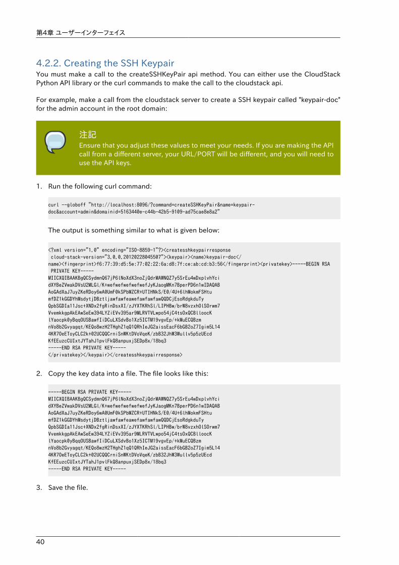
第4章 ユーザーインターフェイス
40
4.2.2. Creating the SSH KeypairYou must make a call to the createSSHKeyPair api method. You can either use the CloudStackPython API library or the curl commands to make the call to the cloudstack api.
For example, make a call from the cloudstack server to create a SSH keypair called "keypair-doc"for the admin account in the root domain:
注記Ensure that you adjust these values to meet your needs. If you are making the APIcall from a different server, your URL/PORT will be different, and you will need touse the API keys.
1. Run the following curl command:
curl --globoff "http://localhost:8096/?command=createSSHKeyPair&name=keypair-doc&account=admin&domainid=5163440e-c44b-42b5-9109-ad75cae8e8a2"
The output is something similar to what is given below:
<?xml version="1.0" encoding="ISO-8859-1"?><createsshkeypairresponse cloud-stack-version="3.0.0.20120228045507"><keypair><name>keypair-doc</name><fingerprint>f6:77:39:d5:5e:77:02:22:6a:d8:7f:ce:ab:cd:b3:56</fingerprint><privatekey>-----BEGIN RSA PRIVATE KEY-----MIICXQIBAAKBgQCSydmnQ67jP6lNoXdX3noZjQdrMAWNQZ7y5SrEu4wDxplvhYcidXYBeZVwakDVsU2MLGl/K+wefwefwefwefwefJyKJaogMKn7BperPD6n1wIDAQABAoGAdXaJ7uyZKeRDoy6wA0UmF0kSPbMZCR+UTIHNkS/E0/4U+6lhMokmFSHtumfDZ1kGGDYhMsdytjDBztljawfawfeawefawfawfawQQDCjEsoRdgkduTyQpbSGDIa11Jsc+XNDx2fgRinDsxXI/zJYXTKRhSl/LIPHBw/brW8vzxhOlSOrwm7VvemkkgpAkEAwSeEw394LYZiEVv395ar9MLRVTVLwpo54jC4tsOxQCBlloocKlYaocpk0yBqqOUSBawfIiDCuLXSdvBo1Xz5ICTM19vgvEp/+kMuECQBzmnVo8b2Gvyagqt/KEQo8wzH2THghZ1qQ1QRhIeJG2aissEacF6bGB2oZ7Igim5L144KR7OeEToyCLC2k+02UCQQCrniSnWKtDVoVqeK/zbB32JhW3Wullv5p5zUEcdKfEEuzcCUIxtJYTahJ1pvlFkQ8anpuxjSEDp8x/18bq3-----END RSA PRIVATE KEY-----</privatekey></keypair></createsshkeypairresponse>
2. Copy the key data into a file. The file looks like this:
-----BEGIN RSA PRIVATE KEY-----MIICXQIBAAKBgQCSydmnQ67jP6lNoXdX3noZjQdrMAWNQZ7y5SrEu4wDxplvhYcidXYBeZVwakDVsU2MLGl/K+wefwefwefwefwefJyKJaogMKn7BperPD6n1wIDAQABAoGAdXaJ7uyZKeRDoy6wA0UmF0kSPbMZCR+UTIHNkS/E0/4U+6lhMokmFSHtumfDZ1kGGDYhMsdytjDBztljawfawfeawefawfawfawQQDCjEsoRdgkduTyQpbSGDIa11Jsc+XNDx2fgRinDsxXI/zJYXTKRhSl/LIPHBw/brW8vzxhOlSOrwm7VvemkkgpAkEAwSeEw394LYZiEVv395ar9MLRVTVLwpo54jC4tsOxQCBlloocKlYaocpk0yBqqOUSBawfIiDCuLXSdvBo1Xz5ICTM19vgvEp/+kMuECQBzmnVo8b2Gvyagqt/KEQo8wzH2THghZ1qQ1QRhIeJG2aissEacF6bGB2oZ7Igim5L144KR7OeEToyCLC2k+02UCQQCrniSnWKtDVoVqeK/zbB32JhW3Wullv5p5zUEcdKfEEuzcCUIxtJYTahJ1pvlFkQ8anpuxjSEDp8x/18bq3-----END RSA PRIVATE KEY-----
3. Save the file.
Creating an Instance
41
4.2.3. Creating an InstanceAfter you save the SSH keypair file, you must create an instance by using the template that youcreated at � Creating an Instance Template that Supports SSH Keys�. Ensure that you use the sameSSH key name that you created at �Creating the SSH Keypair�.
注記You cannot create the instance by using the GUI at this time and associate theinstance with the newly created SSH keypair.
A sample curl command to create a new instance is:
curl --globoff http://localhost:<port number>/?command=deployVirtualMachine\&zoneId=1\&serviceOfferingId=18727021-7556-4110-9322-d625b52e0813\&templateId=e899c18a-ce13-4bbf-98a9-625c5026e0b5\&securitygroupids=ff03f02f-9e3b-48f8-834d-91b822da40c5\&account=admin\&domainid=1\&keypair=keypair-doc
Substitute the template, service offering and security group IDs (if you are using the security groupfeature) that are in your cloud environment.
4.2.4. Logging In Using the SSH KeypairTo test your SSH key generation is successful, check whether you can log in to the cloud setup.
For exaple, from a Linux OS, run:
ssh -i ~/.ssh/keypair-doc <ip address>
The -i parameter tells the ssh client to use a ssh key found at ~/.ssh/keypair-doc.
4.2.5. Resetting SSH KeysWith the API command resetSSHKeyForVirtualMachine, a user can set or reset the SSH keypairassigned to a virtual machine. A lost or compromised SSH keypair can be changed, and the usercan access the VM by using the new keypair. Just create or register a new keypair, then callresetSSHKeyForVirtualMachine.

42
43
Steps to Provisioning Your Cloud InfrastructureThis section tells how to add regions, zones, pods, clusters, hosts, storage, and networks to yourcloud. If you are unfamiliar with these entities, please begin by looking through 2������������������������.
5.1. プロビジョニングの概要管理サーバーのインストールや稼働後、新しいコンピューティングリソースを管理のために追加することができます。CloudStack クラウドインストラクチャがどのように組織化されるかに関しては ������������������� を参照してください。
クラウドインフラストラクチャを展開する、必要な時にスケールアップするには以下の手順に従ってください。
1. Define regions (optional). See ��������� (�����)�.
2. Add a zone to the region. See ��������.
3. Add more pods to the zone (optional). See ��������.
4. Add more clusters to the pod (optional). See ���������.
5. Add more hosts to the cluster (optional). See ��������.
6. Add primary storage to the cluster. See ���������������.
7. Add secondary storage to the zone. See ���������������.
8. 新規クラウドの作成、テストに関しては ��������� を参照してください。
これらの手順が完了したら、以下の一般的な構成を参考に展開することができます。
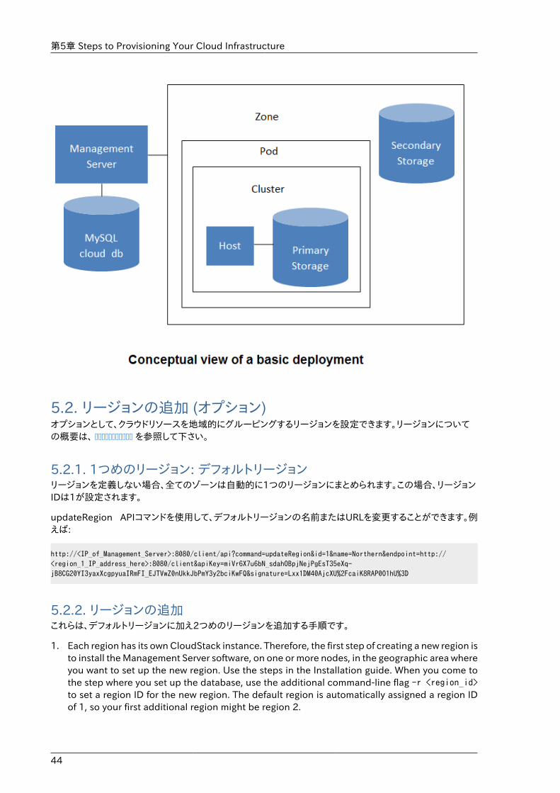
第5章 Steps to Provisioning Your Cloud Infrastructure
44
5.2. リージョンの追加 (オプション)オプションとして、クラウドリソースを地域的にグルーピングするリージョンを設定できます。リージョンについての概要は、 ����������� を参照して下さい。
5.2.1. 1つめのリージョン: デフォルトリージョンリージョンを定義しない場合、全てのゾーンは自動的に1つのリージョンにまとめられます。この場合、リージョンIDは1が設定されます。
updateRegion APIコマンドを使用して、デフォルトリージョンの名前またはURLを変更することができます。例えば:
http://<IP_of_Management_Server>:8080/client/api?command=updateRegion&id=1&name=Northern&endpoint=http://<region_1_IP_address_here>:8080/client&apiKey=miVr6X7u6bN_sdahOBpjNejPgEsT35eXq-jB8CG20YI3yaxXcgpyuaIRmFI_EJTVwZ0nUkkJbPmY3y2bciKwFQ&signature=Lxx1DM40AjcXU%2FcaiK8RAP0O1hU%3D
5.2.2. リージョンの追加これらは、デフォルトリージョンに加え2つめのリージョンを追加する手順です。
1. Each region has its own CloudStack instance. Therefore, the first step of creating a new region isto install the Management Server software, on one or more nodes, in the geographic area whereyou want to set up the new region. Use the steps in the Installation guide. When you come tothe step where you set up the database, use the additional command-line flag -r <region_id>to set a region ID for the new region. The default region is automatically assigned a region IDof 1, so your first additional region might be region 2.
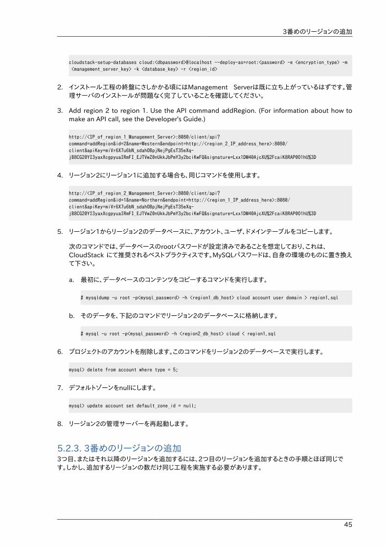
3番めのリージョンの追加
45
cloudstack-setup-databases cloud:<dbpassword>@localhost --deploy-as=root:<password> -e <encryption_type> -m <management_server_key> -k <database_key> -r <region_id>
2. インストール工程の終盤にさしかかる頃にはManagement Serverは既に立ち上がっているはずです。管理サーバのインストールが問題なく完了していることを確認してください。
3. Add region 2 to region 1. Use the API command addRegion. (For information about how tomake an API call, see the Developer's Guide.)
http://<IP_of_region_1_Management_Server>:8080/client/api?command=addRegion&id=2&name=Western&endpoint=http://<region_2_IP_address_here>:8080/client&apiKey=miVr6X7u6bN_sdahOBpjNejPgEsT35eXq-jB8CG20YI3yaxXcgpyuaIRmFI_EJTVwZ0nUkkJbPmY3y2bciKwFQ&signature=Lxx1DM40AjcXU%2FcaiK8RAP0O1hU%3D
4. リージョン2にリージョン1に追加する場合も、同じコマンドを使用します。
http://<IP_of_region_2_Management_Server>:8080/client/api?command=addRegion&id=1&name=Northern&endpoint=http://<region_1_IP_address_here>:8080/client&apiKey=miVr6X7u6bN_sdahOBpjNejPgEsT35eXq-jB8CG20YI3yaxXcgpyuaIRmFI_EJTVwZ0nUkkJbPmY3y2bciKwFQ&signature=Lxx1DM40AjcXU%2FcaiK8RAP0O1hU%3D
5. リージョン1からリージョン2のデータベースに、アカウント、ユーザ、ドメインテーブルをコピーします。
次のコマンドでは、データベースのrootパスワードが設定済みであることを想定しており、これは、CloudStack にて推奨されるベストプラクティスです。MySQLパスワードは、自身の環境のものに置き換えて下さい。
a. 最初に、データベースのコンテンツをコピーするコマンドを実行します。
# mysqldump -u root -p<mysql_password> -h <region1_db_host> cloud account user domain > region1.sql
b. そのデータを、下記のコマンドでリージョン2のデータベースに格納します。
# mysql -u root -p<mysql_password> -h <region2_db_host> cloud < region1.sql
6. プロジェクトのアカウントを削除します。このコマンドをリージョン2のデータベースで実行します。
mysql> delete from account where type = 5;
7. デフォルトゾーンをnullにします。
mysql> update account set default_zone_id = null;
8. リージョン2の管理サーバーを再起動します。
5.2.3. 3番めのリージョンの追加3つ目、またはそれ以降のリージョンを追加するには、2つ目のリージョンを追加するときの手順とほぼ同じです。しかし、追加するリージョンの数だけ同じ工程を実施する必要があります。
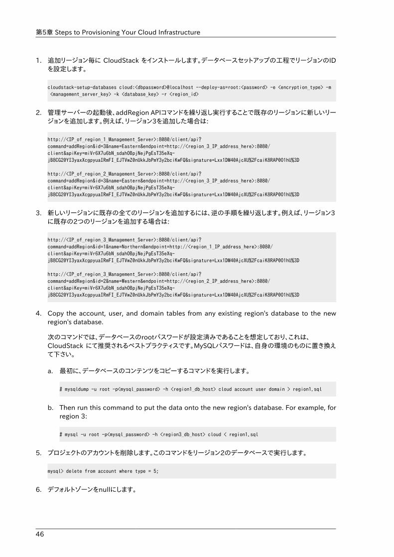
第5章 Steps to Provisioning Your Cloud Infrastructure
46
1. 追加リージョン毎に CloudStack をインストールします。データベースセットアップの工程でリージョンのIDを設定します。
cloudstack-setup-databases cloud:<dbpassword>@localhost --deploy-as=root:<password> -e <encryption_type> -m <management_server_key> -k <database_key> -r <region_id>
2. 管理サーバーの起動後、addRegion APIコマンドを繰り返し実行することで既存のリージョンに新しいリージョンを追加します。例えば、リージョン3を追加した場合は:
http://<IP_of_region_1_Management_Server>:8080/client/api?command=addRegion&id=3&name=Eastern&endpoint=http://<region_3_IP_address_here>:8080/client&apiKey=miVr6X7u6bN_sdahOBpjNejPgEsT35eXq-jB8CG20YI3yaxXcgpyuaIRmFI_EJTVwZ0nUkkJbPmY3y2bciKwFQ&signature=Lxx1DM40AjcXU%2FcaiK8RAP0O1hU%3D
http://<IP_of_region_2_Management_Server>:8080/client/api?command=addRegion&id=3&name=Eastern&endpoint=http://<region_3_IP_address_here>:8080/client&apiKey=miVr6X7u6bN_sdahOBpjNejPgEsT35eXq-jB8CG20YI3yaxXcgpyuaIRmFI_EJTVwZ0nUkkJbPmY3y2bciKwFQ&signature=Lxx1DM40AjcXU%2FcaiK8RAP0O1hU%3D
3. 新しいリージョンに既存の全てのリージョンを追加するには、逆の手順を繰り返します。例えば、リージョン3に既存の2つのリージョンを追加する場合は:
http://<IP_of_region_3_Management_Server>:8080/client/api?command=addRegion&id=1&name=Northern&endpoint=http://<region_1_IP_address_here>:8080/client&apiKey=miVr6X7u6bN_sdahOBpjNejPgEsT35eXq-jB8CG20YI3yaxXcgpyuaIRmFI_EJTVwZ0nUkkJbPmY3y2bciKwFQ&signature=Lxx1DM40AjcXU%2FcaiK8RAP0O1hU%3D
http://<IP_of_region_3_Management_Server>:8080/client/api?command=addRegion&id=2&name=Western&endpoint=http://<region_2_IP_address_here>:8080/client&apiKey=miVr6X7u6bN_sdahOBpjNejPgEsT35eXq-jB8CG20YI3yaxXcgpyuaIRmFI_EJTVwZ0nUkkJbPmY3y2bciKwFQ&signature=Lxx1DM40AjcXU%2FcaiK8RAP0O1hU%3D
4. Copy the account, user, and domain tables from any existing region's database to the newregion's database.
次のコマンドでは、データベースのrootパスワードが設定済みであることを想定しており、これは、CloudStack にて推奨されるベストプラクティスです。MySQLパスワードは、自身の環境のものに置き換えて下さい。
a. 最初に、データベースのコンテンツをコピーするコマンドを実行します。
# mysqldump -u root -p<mysql_password> -h <region1_db_host> cloud account user domain > region1.sql
b. Then run this command to put the data onto the new region's database. For example, forregion 3:
# mysql -u root -p<mysql_password> -h <region3_db_host> cloud < region1.sql
5. プロジェクトのアカウントを削除します。このコマンドをリージョン2のデータベースで実行します。
mysql> delete from account where type = 5;
6. デフォルトゾーンをnullにします。
リージョンの削除
47
mysql> update account set default_zone_id = null;
7. 新しいリージョンで管理サーバーを再起動します。
5.2.4. リージョンの削除リージョンを削除するには、removeRegion APIコマンドを使用します。全てのリージョンからリージョン情報を削除するため、これを繰り返し実行します。例えば、3つのリージョンの3番めのリージョンを削除するには:
http://<IP_of_region_1_Management_Server>:8080/client/api?command=removeRegion&id=3&apiKey=miVr6X7u6bN_sdahOBpjNejPgEsT35eXq-jB8CG20YI3yaxXcgpyuaIRmFI_EJTVwZ0nUkkJbPmY3y2bciKwFQ&signature=Lxx1DM40AjcXU%2FcaiK8RAP0O1hU%3D
http://<IP_of_region_2_Management_Server>:8080/client/api?command=removeRegion&id=3&apiKey=miVr6X7u6bN_sdahOBpjNejPgEsT35eXq-jB8CG20YI3yaxXcgpyuaIRmFI_EJTVwZ0nUkkJbPmY3y2bciKwFQ&signature=Lxx1DM40AjcXU%2FcaiK8RAP0O1hU%3D
5.3. ゾーンの追加次の手順は、CloudStack ユーザーインターフェイスにログオン済みであることを前提としています(�UI�������を参照)。
1. (オプション)クラウド全体のセカンダリストレージとして Swift を使用する場合は、ゾーンを追加する前にSwift を追加する必要があります。
a. CloudStackユーザーインターフェイスに管理者としてログオンします。
b. 初めてユーザーインターフェイスを使用する場合は、ガイドツアーのスプラッシュページが開きます。\n[Experienced user]を選択します。ダッシュボードが開きます。
c. 左側のナビゲーションバーで[Global Settings]をクリックします。
d. 検索ボックスに「swift.enable」と入力して検索ボタンをクリックします。
e.[Edit]アイコンをクリックして swift.enable を true に設定します。
f. 管理サーバーを再起動します。
# service cloudstack-management restart
g. CloudStack ユーザーインターフェイスが表示されている Web ブラウザータブを更新して再度ログオンします。
2. 左側のナビゲーションバーで[Infrastructure]をクリックします。
3. [Zones]で[View More]をクリックします。
4. (オプション)Swift ストレージを使用する場合は、[Edit Swift]をクリックします。次の情報を指定します。
• URL : Swift URL です。
• Account : Swift アカウントです。
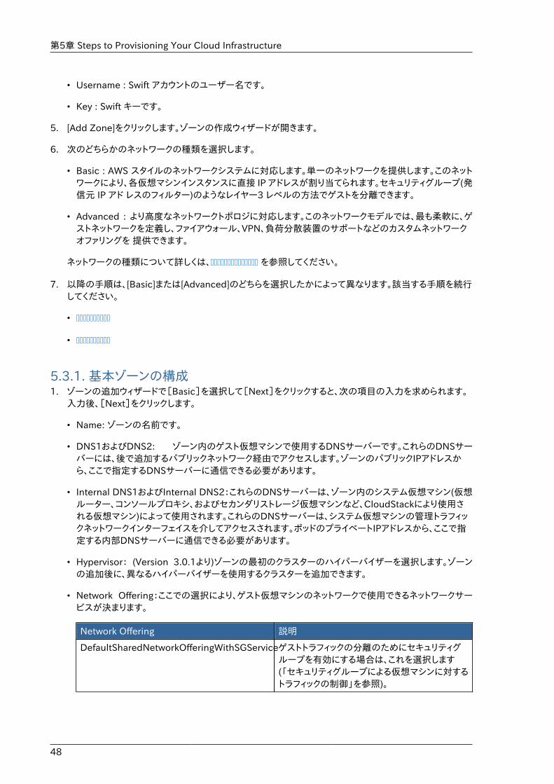
第5章 Steps to Provisioning Your Cloud Infrastructure
48
• Username : Swift アカウントのユーザー名です。
• Key : Swift キーです。
5. [Add Zone]をクリックします。ゾーンの作成ウィザードが開きます。
6. 次のどちらかのネットワークの種類を選択します。
• Basic : AWS スタイルのネットワークシステムに対応します。単一のネットワークを提供します。このネットワークにより、各仮想マシンインスタンスに直接 IP アドレスが割り当てられます。セキュリティグループ(発信元 IP アド レスのフィルター)のようなレイヤー3 レベルの方法でゲストを分離できます。
• Advanced : より高度なネットワークトポロジに対応します。このネットワークモデルでは、最も柔軟に、ゲストネットワークを定義し、ファイアウォール、VPN、負荷分散装置のサポートなどのカスタムネットワークオファリングを 提供できます。
ネットワークの種類について詳しくは、�������������� を参照してください。
7. 以降の手順は、[Basic]または[Advanced]のどちらを選択したかによって異なります。該当する手順を続行してください。
• ����������
• ����������
5.3.1. 基本ゾーンの構成1. ゾーンの追加ウィザードで[Basic]を選択して[Next]をクリックすると、次の項目の入力を求められます。
入力後、[Next]をクリックします。
• Name: ゾーンの名前です。
• DNS1およびDNS2: ゾーン内のゲスト仮想マシンで使用するDNSサーバーです。これらのDNSサーバーには、後で追加するパブリックネットワーク経由でアクセスします。ゾーンのパブリックIPアドレスから、ここで指定するDNSサーバーに通信できる必要があります。
• Internal DNS1およびInternal DNS2:これらのDNSサーバーは、ゾーン内のシステム仮想マシン(仮想ルーター、コンソールプロキシ、およびセカンダリストレージ仮想マシンなど、CloudStackにより使用される仮想マシン)によって使用されます。これらのDNSサーバーは、システム仮想マシンの管理トラフィックネットワークインターフェイスを介してアクセスされます。ポッドのプライベートIPアドレスから、ここで指定する内部DNSサーバーに通信できる必要があります。
• Hypervisor: (Version 3.0.1より)ゾーンの最初のクラスターのハイパーバイザーを選択します。ゾーンの追加後に、異なるハイパーバイザーを使用するクラスターを追加できます。
• Network Offering:ここでの選択により、ゲスト仮想マシンのネットワークで使用できるネットワークサービスが決まります。
Network Offering 説明
DefaultSharedNetworkOfferingWithSGServiceゲストトラフィックの分離のためにセキュリティグループを有効にする場合は、これを選択します(「セキュリティグループによる仮想マシンに対するトラフィックの制御」を参照)。
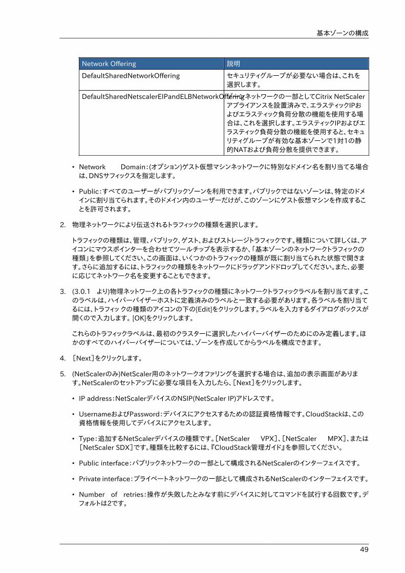
基本ゾーンの構成
49
Network Offering 説明
DefaultSharedNetworkOffering セキュリティグループが必要ない場合は、これを選択します。
DefaultSharedNetscalerEIPandELBNetworkOfferingゾーンネットワークの一部としてCitrix NetScalerアプライアンスを設置済みで、エラスティックIPおよびエラスティック負荷分散の機能を使用する場合は、これを選択します。エラスティックIPおよびエラスティック負荷分散の機能を使用すると、セキュリティグループが有効な基本ゾーンで1対1の静的NATおよび負荷分散を提供できます。
• Network Domain:(オプション)ゲスト仮想マシンネットワークに特別なドメイン名を割り当てる場合は、DNSサフィックスを指定します。
• Public:すべてのユーザーがパブリックゾーンを利用できます。パブリックではないゾーンは、特定のドメインに割り当てられます。そのドメイン内のユーザーだけが、このゾーンにゲスト仮想マシンを作成することを許可されます。
2. 物理ネットワークにより伝送されるトラフィックの種類を選択します。
トラフィックの種類は、管理、パブリック、ゲスト、およびストレージトラフィックです。種類について詳しくは、アイコンにマウスポインターを合わせてツールチップを表示するか、「基本ゾーンのネットワークトラフィックの種類」を参照してください。この画面は、いくつかのトラフィックの種類が既に割り当てられた状態で開きます。さらに追加するには、トラフィックの種類をネットワークにドラッグアンドドロップしてください。また、必要に応じてネットワーク名を変更することもできます。
3. (3.0.1 より)物理ネットワーク上の各トラフィックの種類にネットワークトラフィックラベルを割り当てます。このラベルは、ハイパーバイザーホストに定義済みのラベルと一致する必要があります。各ラベルを割り当てるには、トラフィッ クの種類のアイコンの下の[Edit]をクリックします。ラベルを入力するダイアログボックスが開くので入力します。 [OK]をクリックします。
これらのトラフィックラベルは、最初のクラスターに選択したハイパーバイザーのためにのみ定義します。ほかのすべてのハイパーバイザーについては、ゾーンを作成してからラベルを構成できます。
4. [Next]をクリックします。
5. (NetScalerのみ)NetScaler用のネットワークオファリングを選択する場合は、追加の表示画面があります。NetScalerのセットアップに必要な項目を入力したら、[Next]をクリックします。
• IP address:NetScalerデバイスのNSIP(NetScaler IP)アドレスです。
• UsernameおよびPassword:デバイスにアクセスするための認証資格情報です。CloudStackは、この資格情報を使用してデバイスにアクセスします。
• Type:追加するNetScalerデバイスの種類です。[NetScaler VPX]、[NetScaler MPX]、または[NetScaler SDX]です。種類を比較するには、『CloudStack管理ガイド』を参照してください。
• Public interface:パブリックネットワークの一部として構成されるNetScalerのインターフェイスです。
• Private interface:プライベートネットワークの一部として構成されるNetScalerのインターフェイスです。
• Number of retries:操作が失敗したとみなす前にデバイスに対してコマンドを試行する回数です。デフォルトは2です。
第5章 Steps to Provisioning Your Cloud Infrastructure
50
• Capacity:このNetScalerデバイスを共有するゲストネットワーク/アカウントの数です。
• Dedicated:専用のデバイスは単一のアカウント専用になります。[Dedicated]チェックボックスをオンにすると、[Capacity]ボックスの値は無視され、暗黙的に1であるとみなされます。
6. (NetScalerのみ)パブリックトラフィックのIPアドレスの範囲を構成します。この範囲内のIPアドレスは、EIPおよびELBが有効なNetScalerのネットワークオファリングを選択することによって有効にする、静的NAT機能に使用されます。次の詳細情報を入力し、[Add]をクリックします。必要に応じてこの手順を繰り返し、さらにIPアドレスの範囲を追加できます。完了したら[Next]をクリックします。
• Gateway:これらのIPアドレスに使用するゲートウェイです。
• Netmask:このIPアドレスの範囲に関連付けるネットマスクです。
• VLAN:パブリックトラフィックに使用するVLANです。
• Start IPおよびEnd IP:インターネットからアクセスできるとみなされるIPアドレスの範囲で、ゲスト仮想マシンへのアクセスのために割り当てます。
7. 新しいゾーンでは、CloudStackにより最初のポッドが自動的に追加されます。後でさらにポッドを追加できます。ポッドの概要については、「ポッドについて」を参照してください。
最初のポッドを構成するには、次の項目を入力して[Next]をクリックします。
• Pod Name:ポッドの名前です。
• Reserved system gateway:このポッド内のホストのゲートウェイです。
• Reserved system netmask. The network prefix that defines the pod's subnet. Use CIDRnotation.
• Start Reserved System IPおよびEnd Reserved System IP:セカンダリストレージ仮想マシン、コンソールプロキシ仮想マシン、およびDHCPなどのさまざまなシステム仮想マシンを管理するために、CloudStackで使用する管理ネットワーク内のIPアドレスの範囲です。詳しくは、「システムにより予約済みのIPアドレス」を参照してください。
8. ゲストトラフィック用のネットワークを構成します。次の情報を指定してから、[Next]をクリックします。
• Guest gateway:ゲストが使用するゲートウェイです。
• Guest netmask:ゲストの使用するサブネット上で使用されるネットマスクです。
• Guest start IPおよびGuest end IP:CloudStackがゲストに割り当てられるIPアドレスの範囲を定義する、最初と最後のIPアドレスを入力します。
• 複数のNICを使用することを強くお勧めします。複数のNICを使用する場合は、別のサブネットに存在するIPアドレスを入力できます。
• NICを1つ使用する場合は、これらのIPアドレスは、ポッドのCIDRと同じCIDRに存在する必要があります。
9. 新しいポッドでは、CloudStackにより最初のクラスターが自動的に追加されます。後でさらにクラスターを追加できます。クラスターの概要については、「クラスターについて」を参照してください。
最初のクラスターを構成するには、次の項目を入力して[Next]をクリックします。
基本ゾーンの構成
51
• Hypervisor:(Version 3.0.0のみ。3.0.1では読み取り専用)このクラスター内のすべてのホストで実行される、ハイパーバイザーソフトウェアの種類を選択します。VMwareを選択すると追加のフィールドが表示され、vSphereクラスターに関する情報を指定できます。vSphereサーバーの場合は、vCenterでホストのクラスターを作成した後、クラスター全体をCloudStackに追加することをお勧めします。「クラスターの追加:vSphere」を参照してください。
• Cluster name:クラスターの名前を入力します。任意の、CloudStackで使用されていないテキストを指定します。
10. 新しいクラスターでは、CloudStackにより最初のホストが自動的に追加されます。後でさらにホストを追加できます。ホストの概要については、「ホストについて」を参照してください。
注記CloudStackを展開するときに、ハイパーバイザーに実行中の仮想マシンがあってはいけません。
ホストを構成する前に、ハイパーバイザーソフトウェアをホストにインストールする必要があります。CloudStackがサポートするハイパーバイザーソフトウェアのバージョン、およびホストをCloudStackと連動させるために必要な追加構成を確認しておく必要があります。このインストールについて詳しくは、次のセクションを参照してください。
• Citrix XenServerのインストールと構成
• VMware vSphereのインストールと構成
• KVMのインストールと構成
最初のホストを構成するには、次の項目を入力して[Next]をクリックします。
• Host Name:ホストのDNS名またはIPアドレスです。
• Username:通常はrootです。
• Password:上のユーザー名に対するパスワードです(XenServerまたはKVM側で指定したもの)。
• Host Tags. (Optional) Any labels that you use to categorize hosts for ease of maintenance.For example, you can set this to the cloud's HA tag (set in the ha.tag global configurationparameter) if you want this host to be used only for VMs with the "high availability" featureenabled. For more information, see HA-Enabled Virtual Machines as well as HA for Hosts.
11. 新しいクラスターでは、CloudStack により最初のプライマリストレージサーバーが自動的に追加されます。後でさらにサーバーを追加できます。プライマリストレージの概要については、「プライマリストレージについて」を参照してください。
最初のプライマリストレージサーバーを構成するには、次の項目を入力して[Next]をクリックします。
• Name:ストレージデバイスの名前です。
• Protocol : XenServer の場合は、[NFS]、[iSCSI]、または[PreSetup]を選択します。KVM の場合は、[NFS]、[SharedMountPoint]、[CLVM]または[RBD]を選択します。vSphere の場合は、[VMFS](iSCSIまたはファイバーチャネル)または [NFS]を選択します。画面のそのほかのフィールドは、ここで選択したものにより異なります。
第5章 Steps to Provisioning Your Cloud Infrastructure
52
5.3.2. 拡張ゾーンの構成1. ゾーンの追加ウィザードで[Advanced]を選択して[Next]をクリックすると、次の詳細の入力を求められま
す。入力後、[Next]をクリックします。
• Name : ゾーンの名前です。
• DNS1およびDNS2 : ゾーン内のゲスト仮想マシンで使用するDNSサーバーです。これらのDNSサーバーには、後で追加するパブリックネットワーク経由でアクセスします。ゾーンのパブリックIPアドレスから、ここで指定するDNSサーバーに通信できる必要があります。
• Internal DNS1 および Internal DNS2 : これらの DNS サーバーは、ゾーン内のシステム仮想マシン(仮想ルーター、 コンソールプロキシ、およびセカンダリストレージ仮想マシンなど、CloudStack により使用される仮想マシン)に よって使用されます。これらの DNS サーバーは、システム仮想マシンの管理トラフィックネットワークインターフェイスを介してアクセスされます。ポッドのプライベート IP アドレスから、ここで指定する内部 DNS サーバーに通信できる必要があります。
• Network Domain : (オプション)ゲスト仮想マシンネットワークに特別なドメイン名を割り当てる場合は、DNSサフィックスを指定します。
• Guest CIDR : このゾーンのゲスト仮想ネットワークで使用される IP アドレスを記述する CIDR です。これはたとえば、10.1.1.0/24 です。ゾーンごとに異なる CIDR を設定することをお勧めします。これにより、異なるゾーンのネットワーク間で簡単に VPN をセットアップできるようになります。
• Hypervisor : (Version 3.0.1より) ゾーンの最初のクラスターのハイパーバイザーを選択します。ゾーンの追加後に、異なるハイパーバイザーを使用するクラスターを追加できます。
• Public : すべてのユーザーがパブリックゾーンを利用できます。パブリックではないゾーンは、特定のドメインに割り当てられます。そのドメイン内のユーザーだけが、このゾーンにゲスト仮想マシンを作成することを許可されます。
2. 物理ネットワークにより伝送されるトラフィックの種類を選択します。
トラフィックの種類は、管理、パブリック、ゲスト、およびストレージトラフィックです。種類について詳しくは、アイコンにマウスポインターを合わせてツールチップを表示するか、����������������������� を参照してください。この画面が表示される時点で、1 つのネットワークが既に構成されています。複数の物理ネットワークがある場合は、ネットワークを追加する必要があります。トラフィックの種類をドラッグして非アクティブなネットワークにドロップすると、ネットワークがアクティブになります。トラフィックアイコンをネットワーク間で移動でき ます。たとえば、Network 1 に表示されているデフォルトのトラフィックの種類が実際の設定と一致しない場合は、トラフィックの種類を移動できます。また、必要に応じてネットワーク名を変更することもできます。
3. (Version 3.0.1 より)各物理ネットワーク上の各トラフィックの種類にネットワークトラフィックラベルを割り当てます。このラベルは、ハイパーバイザーホストに定義済みのラベルと一致する必要があります。各ラベルを割り当てるには、各物理ネットワーク内のトラフィックの種類のアイコンの下の[Edit] をクリックします。ラベルを入力するダイアログボック スが開くので入力します。[OK] をクリックします。
これらのトラフィックラベルは、最初のクラスターに選択したハイパーバイザーのためにのみ定義します。ほかのすべてのハイパーバイザーについては、ゾーンを作成してからラベルを構成できます。
4. [Next]をクリックします。
5. パブリックインターネットトラフィックの IP アドレスの範囲を構成します。次の詳細情報を入力し、[Add]をクリックしま す。必要に応じてこの手順を繰り返し、さらにパブリックインターネットの IP アドレスの範囲を追加できます。完了し たら[Next]をクリックします。
拡張ゾーンの構成
53
• Gateway : これらのIPアドレスに使用するゲートウェイです。
• Netmask : このIPアドレスの範囲に関連付けるネットマスクです。
• VLAN : パブリックトラフィックに使用するVLANです。
• Start IP および End IP : インターネットからアクセスできるとみなされる IP アドレスの範囲で、ゲストネットワークへのアクセスのために割り当てます。
6. 新しいゾーンでは、CloudStackにより最初のポッドが自動的に追加されます。後でさらにポッドを追加できます。ポッドの概要については、��������� を参照してください。
最初のポッドを構成するには、次の項目を入力して[Next]をクリックします。
• Pod Name : ポッドの名前です。
• Reserved system gateway : このポッド内のホストのゲートウェイです。
• Reserved system netmask. The network prefix that defines the pod's subnet. Use CIDRnotation.
• Start Reserved System IP および End Reserved System IP : セカンダリストレージ仮想マシン、コンソールプロキシ仮想マシン、および DHCP などのさまざまなシステム仮想マシンを管理するために、CloudStack で使用する管理ネットワーク内の IP アドレスの範囲です。詳しくは、������������� IP �����を 参照してください。
7. 各物理ネットワークのゲストトラフィックを伝送する VLAN ID の範囲を指定して(「VLAN 割り当ての例」)、[Next] をクリックします。
8. 新しいポッドでは、CloudStack により最初のクラスターが自動的に追加されます。後でさらにクラスターを追加できます。クラスターの概要については、���������� を参照してください。
最初のクラスターを構成するには、次の項目を入力して[Next]をクリックします。
• Hypervisor : (Version 3.0.0 のみ。3.0.1 では読み取り専用)このクラスター内のすべてのホストで実行される、ハイパーバイザーソフトウェアの種類を選択します。VMware を選択すると追加のフィールドが表示され、vSphere クラスターに関する情報を指定できます。vSphere サーバーの場合は、vCenter でホストのクラスターを作成した後、クラスター全体を CloudStack に追加することをお勧めします。「クラスターの追加:vSphere」 参照してください。
• Cluster name : クラスターの名前を入力します。任意の、CloudStackで使用されていないテキストを指定します。
9. 新しいクラスターでは、CloudStack により最初のホストが自動的に追加されます。後でさらにホストを追加できます。\nホストの概要については、��������� を参照してください。
注記CloudStack を展開するときに、ハイパーバイザーに実行中の仮想マシンがあってはいけません。
ホストを構成する前に、ハイパーバイザーソフトウェアをホストにインストールする必要があります。CloudStackがサポートするハイパーバイザーソフトウェアのバージョン、およびホストをCloudStackと
第5章 Steps to Provisioning Your Cloud Infrastructure
54
連動させるために必要な追加構成を確認しておく必要があります。このインストールについて詳しくは、次のセクションを参照してください。
• CloudStackのためのCitrix XenServerのインストール
• VMware vSphereのインストールと設定
• KVMのインストールと設定
最初のホストを構成するには、次の項目を入力して[Next]をクリックします。
• Host Name : ホストのDNS名またはIPアドレスです。
• Username : 通常は root です。
• Password : 上のユーザー名に対するパスワードです(XenServerまたはKVM側で指定したもの)。
• Host Tags. (Optional) Any labels that you use to categorize hosts for ease of maintenance. Forexample, you can set to the cloud's HA tag (set in the ha.tag global configuration parameter)if you want this host to be used only for VMs with the "high availability" feature enabled.For more information, see HA-Enabled Virtual Machines as well as HA for Hosts, both in theAdministration Guide.
10. 新しいクラスターでは、CloudStack により最初のプライマリストレージサーバーが自動的に追加されます。後でさらにサーバーを追加できます。プライマリストレージの概要については、���������������� を参照してください。
最初のプライマリストレージサーバーを構成するには、次の項目を入力して[Next]をクリックします。
• Name : ストレージデバイスの名前です。
• Protocol : XenServer の場合は、[NFS]、[iSCSI]、または[PreSetup]を選択します。KVM の場合は、[NFS]、[SharedMountPoint]、[CLVM]または[RBD]を選択します。vSphere の場合は、[VMFS](iSCSIまたはファイバーチャネル)または [NFS]を選択します。画面のそのほかのフィールドは、ここで選択したものにより異なります。
NFS • Server : ストレージデバイスの IP アドレスまたは DNS 名です。
• Path : サーバーからエクスポートされたパスです。
• Tags(オプション) : このストレージデバイス用のタグをコンマで区切って指定し ます。ディスクオファリングのタグと同等、またはそのスーパーセットである必要があります。
プライマリストレージのタグセットは、ゾーン内のクラスター間で同一である必要があります。たとえば、クラスターA でプライマリストレージのタグがT1 および T2 の場合は、同じゾーン内のほかのすべてのクラスターでもプライマリス トレージのタグを T1 および T2 にする必要があります。
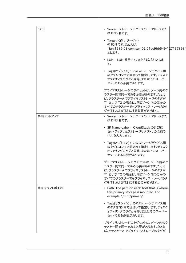
拡張ゾーンの構成
55
iSCSI • Server : ストレージデバイスの IP アドレスまたは DNS 名です。
• Target IQN : ターゲットの IQN です。たとえば、「iqn.1986-03.com.sun:02:01ec9bb549-1271378984」とします。
• LUN : LUN 番号です。たとえば、「3」とします。
• Tags(オプション) : このストレージデバイス用のタグをコンマで区切って指定し ます。ディスクオファリングのタグと同等、またはそのスーパーセットである必要があります。
プライマリストレージのタグセットは、ゾーン内のクラスター間で同一である必要があります。たとえば、クラスターA でプライマリストレージのタグがT1 および T2 の場合は、同じゾーン内のほかのすべてのクラスターでもプライマリス トレージのタグを T1 および T2 にする必要があります。
事前セットアップ • Server : ストレージデバイスの IP アドレスまたは DNS 名です。
• SR Name-Label : CloudStack の外部にセットアップしたストレージリポジトリの名前ラベルを入力します。
• Tags(オプション) : このストレージデバイス用のタグをコンマで区切って指定し ます。ディスクオファリングのタグと同等、またはそのスーパーセットである必要があります。
プライマリストレージのタグセットは、ゾーン内のクラスター間で同一である必要があります。たとえば、クラスターA でプライマリストレージのタグがT1 および T2 の場合は、同じゾーン内のほかのすべてのクラスターでもプライマリス トレージのタグを T1 および T2 にする必要があります。
共有マウントポイント • Path. The path on each host that is wherethis primary storage is mounted. Forexample, "/mnt/primary".
• Tags(オプション) : このストレージデバイス用のタグをコンマで区切って指定し ます。ディスクオファリングのタグと同等、またはそのスーパーセットである必要があります。
プライマリストレージのタグセットは、ゾーン内のクラスター間で同一である必要があります。たとえば、クラスターA でプライマリストレージのタグが
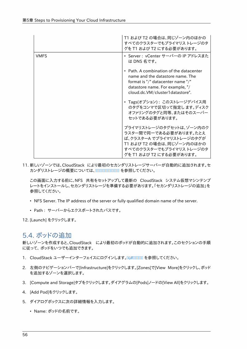
第5章 Steps to Provisioning Your Cloud Infrastructure
56
T1 および T2 の場合は、同じゾーン内のほかのすべてのクラスターでもプライマリス トレージのタグを T1 および T2 にする必要があります。
VMFS • Server : vCenter サーバーの IP アドレスまたは DNS 名です。
• Path. A combination of the datacentername and the datastore name. Theformat is "/" datacenter name "/"datastore name. For example, "/cloud.dc.VM/cluster1datastore".
• Tags(オプション) : このストレージデバイス用のタグをコンマで区切って指定し ます。ディスクオファリングのタグと同等、またはそのスーパーセットである必要があります。
プライマリストレージのタグセットは、ゾーン内のクラスター間で同一である必要があります。たとえば、クラスターA でプライマリストレージのタグがT1 および T2 の場合は、同じゾーン内のほかのすべてのクラスターでもプライマリス トレージのタグを T1 および T2 にする必要があります。
11. 新しいゾーンでは、CloudStack により最初のセカンダリストレージサーバーが自動的に追加されます。セカンダリストレージの概要については、���������������� を参照してください。
この画面に入力する前に、NFS 共有をセットアップして最新の CloudStack システム仮想マシンテンプレートをインストールし、セカンダリストレージを準備する必要があります。「セカンダリストレージの追加」を参照してください。
• NFS Server. The IP address of the server or fully qualified domain name of the server.
• Path : サーバーからエクスポートされたパスです。
12. [Launch] をクリックします。
5.4. ポッドの追加新しいゾーンを作成すると、CloudStack により最初のポッドが自動的に追加されます。このセクションの手順に従って、 ポッドをいつでも追加できます。
1. CloudStack ユーザーインターフェイスにログインします。�UI������� を参照してください。
2. 左側のナビゲーションバーで[Infrastructure]をクリックします。[Zones]で[View More]をクリックし、ポッドを追加するゾーンを選択します。
3. [Compute and Storage]タブをクリックします。ダイアグラムの[Pods]ノードの[View All]をクリックします。
4. [Add Pod]をクリックします。
5. ダイアログボックスに次の詳細情報を入力します。
• Name: ポッドの名前です。
クラスタの追加
57
• Gateway: このポッド内のホストのゲートウェイです。
• Netmask. The network prefix that defines the pod's subnet. Use CIDR notation.
• Start Reserved System IPおよびEnd Reserved System IP: セカンダリストレージ仮想マシン、コンソールプロキシ仮想マシン、およびDHCPなどのさまざまなシステム仮想マシンを管理するために、CloudStack で使用する管理ネットワーク内のIPアドレスの範囲です。詳しくは、「システムにより予約済みのIPアドレス」を参照してください。
6. [OK]をクリックします。
5.5. クラスタの追加CloudStack に管理対象のホストを認識させる必要があります。ホストはクラスター内にあるため、ホストをクラウドに追加するには少なくとも 1 つのクラスターを追加する必要があります。
5.5.1. クラスターの追加:KVM または XenServer次の手順は、ハイパーバイザーをホストにインストール済みで CloudStack ユーザーインターフェイスにログイン済みであることを前提としています。
1. 左側のナビゲーションバーで[Infrastructure]をクリックします。[Zones]で[View More]をクリックし、クラスターを追加するゾーンを選択します。
2. [Compute] タブをクリックします。
3. ダイアグラムの[Clusters]ノードの[View All]をクリックします。
4. [Add Cluster]をクリックします。
5. このクラスターのハイパーバイザーの種類を選択します。
6. クラスターを作成するポッドを選択します。
7. クラスターの名前を入力します。任意の、CloudStack で使用されていないテキストを指定します。
8. [OK]をクリックします。
5.5.2. クラスターの追加:vSpherevSphere のホスト管理は、vCenter および CloudStack の管理者ユーザーインターフェイスを組み合わせて行います。CloudStack では、すべてのホストが CloudStack クラスターにあることが必要ですが、クラスターを単一のホストで構成することもできます。管理者はクラスターに 1 台のホストを使用するか、複数のホストを使用するかを決定する必要があります。 複数ホストのクラスターでは、ライブマイグレーションのような機能を使用できます。クラスターには、NFS または iSCSI のような共有ストレージも必要です。
vSphere サーバーの場合は、vCenter でホストのクラスターを作成した後、クラスター全体を CloudStack に追加することをお勧めします。次の要件に従ってください。
• vSphere クラスターに配置するホストは 8 台までにしてください。
• ハイパーバイザーホストに実行中の仮想マシンがないことを確認してから、CloudStack に追加してください。
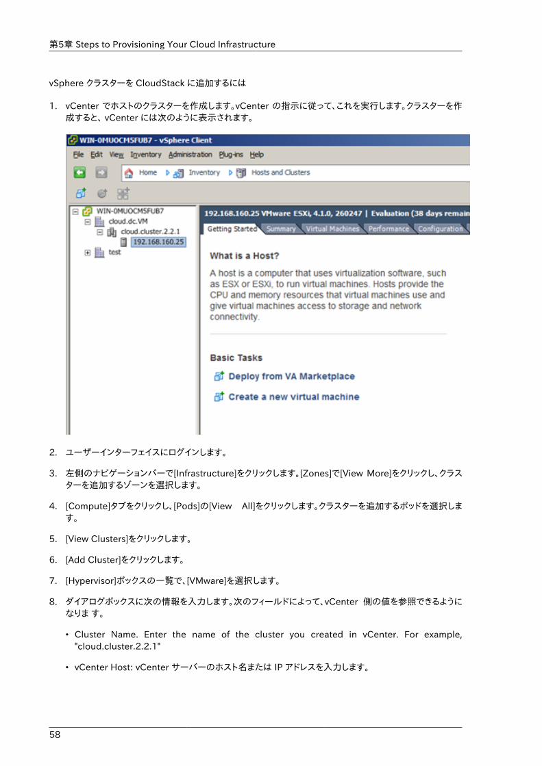
第5章 Steps to Provisioning Your Cloud Infrastructure
58
vSphere クラスターを CloudStack に追加するには
1. vCenter でホストのクラスターを作成します。vCenter の指示に従って、これを実行します。クラスターを作成すると、 vCenter には次のように表示されます。
2. ユーザーインターフェイスにログインします。
3. 左側のナビゲーションバーで[Infrastructure]をクリックします。[Zones]で[View More]をクリックし、クラスターを追加するゾーンを選択します。
4. [Compute]タブをクリックし、[Pods]の[View All]をクリックします。クラスターを追加するポッドを選択します。
5. [View Clusters]をクリックします。
6. [Add Cluster]をクリックします。
7. [Hypervisor]ボックスの一覧で、[VMware]を選択します。
8. ダイアログボックスに次の情報を入力します。次のフィールドによって、vCenter 側の値を参照できるようになりま す。
• Cluster Name. Enter the name of the cluster you created in vCenter. For example,"cloud.cluster.2.2.1"
• vCenter Host: vCenter サーバーのホスト名または IP アドレスを入力します。
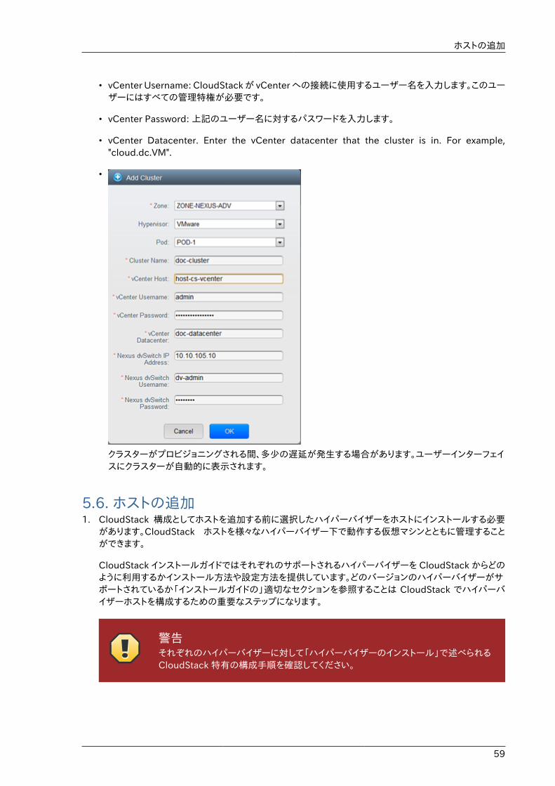
ホストの追加
59
• vCenter Username: CloudStack が vCenter への接続に使用するユーザー名を入力します。このユーザーにはすべての管理特権が必要です。
• vCenter Password: 上記のユーザー名に対するパスワードを入力します。
• vCenter Datacenter. Enter the vCenter datacenter that the cluster is in. For example,"cloud.dc.VM".
•
クラスターがプロビジョニングされる間、多少の遅延が発生する場合があります。ユーザーインターフェイスにクラスターが自動的に表示されます。
5.6. ホストの追加1. CloudStack 構成としてホストを追加する前に選択したハイパーバイザーをホストにインストールする必要
があります。CloudStack ホストを様々なハイパーバイザー下で動作する仮想マシンとともに管理することができます。
CloudStack インストールガイドではそれぞれのサポートされるハイパーバイザーを CloudStack からどのように利用するかインストール方法や設定方法を提供しています。どのバージョンのハイパーバイザーがサポートされているか「インストールガイドの」適切なセクションを参照することは CloudStack でハイパーバイザーホストを構成するための重要なステップになります。
警告それぞれのハイパーバイザーに対して「ハイパーバイザーのインストール」で述べられるCloudStack 特有の構成手順を確認してください。
第5章 Steps to Provisioning Your Cloud Infrastructure
60
2. CloudStack に対しホストを追加します。関連する技術情報は利用するハイパーバイザーによって異なります。
• �������(XenServer ��� KVM)�
• ������� (vSphere)�
5.6.1. ホストの追加(XenServer または KVM)XenServer および KVM のホストは、いつでもクラスターに追加できます。
5.6.1.1. XenServer および KVM ホストの要件
警告�ハイパーバイザーホストに実行中の仮想マ シンがないことを確認してから、CloudStackに追加してください。
構成要件
• 各クラスターには同一のハイパーバイザーを使用するホストのみを含める必要があります。
• XenServer の場合は、クラスターに配置するホストは 8 台までにしてください。
• KVM の場合は、クラスターに配置するホストは 16 台までにしてください。
ハードウェア要件については、CloudStack インストールガイドのハイパーバイザー毎のインストールセクションを参照してください。
5.6.1.1.1. XenServer ホストの追加要件ネットワークボンディングを使用する場合は、管理者はホストの配線を、クラスター内のほかのホストと完全に同じにする必要があります。
クラスターに追加するすべてのホストに対して次のコマンドを実行します。これで、ホストが XenServer プールのマスターに加わります。
# xe pool-join master-address=[master IP] master-username=root master-password=[your password]
注記�コマンドをコピーして実行するときは、単一の行として貼り付けたことを確認してください。一部のドキュメントビューアーでは、コピーしたテキストに不要な改行が含まれる可能性があります。
XenServer プールにすべてのホストを追加したら、cloud-setup-bond スクリプトを実行します。このスクリプトにより、クラスター内の新しいホストのボンドの構成とセットアップを完了します。
1. /usr/lib64/cloud/common/scripts/vm/hypervisor/xenserver/cloud-setup-bonding.sh スクリプトを管理サーバーから マスターホストにコピーし、スクリプトが実行可能であることを確認します。
ホストの追加(XenServer または KVM)
61
2. 次のスクリプトを実行します。
# ./cloud-setup-bonding.sh
5.6.1.1.2. KVM ホストの追加要件• 共有マウントポイントストレージを使用する場合は、管理者は新しいホストのすべてのマウントポイントを(マウ
ントされたストレージも含めて)、クラスター内のほかのホストと完全に同じにする必要があります。
• 新しいホストのネットワーク構成(ゲスト、プライベート、およびパブリックネットワーク)が、クラスター内のほかのホ ストと同じであることを確認してください。
• OpenVswitch のブリッジを利用している場合は CloudStack にホストを追加するまえに KVM ホストのagent.properties を編集し network.bridge.type パラメーターを openvswitch に設定してください。
5.6.1.2. XenServer または KVM ホストの追加• ホストにハイパーバイザーソフトウェアをまだインストールしていない場合はインストールします。CloudStack
がサポートするハイパーバイザーソフトウェアのバージョン、およびホストを CloudStack と連動させるために必要な追加構成を確認しておく必要があります。このインストールの詳細については、CloudStack インストールガイドからハイパーバイザー毎の適切なセクションを参照してください。
• CloudStackユーザーインターフェイスに管理者としてログオンします。
• 左側のナビゲーションバーで[Infrastructure]をクリックします。[Zones]で[View More]をクリックし、ホストを追加するゾーンを選択します。
• [Compute]タブをクリックします。[Clusters]ノードの[View All]をクリックします。
• ホストを追加するクラスターを選択します。
• [View Hosts]をクリックします。
• [Add Host]をクリックします。
• 次の情報を指定します。
• Host Name: ホストの DNS 名または IP アドレスです。
• Username: 通常は root です。
• Password: XenServer または KVM 側で指定した、上のユーザー名に対するパスワードです。
• Host Tags (Optional). Any labels that you use to categorize hosts for ease of maintenance. Forexample, you can set to the cloud's HA tag (set in the ha.tag global configuration parameter)if you want this host to be used only for VMs with the "high availability" feature enabled. Formore information, see HA-Enabled Virtual Machines as well as HA for Hosts.
ホストがプロビジョニングされる間、多少の遅延が発生する場合があります。ユーザーインターフェイスにホストが自動的に表示されます。
• 追加のホストについて、この手順を繰り返します。
第5章 Steps to Provisioning Your Cloud Infrastructure
62
5.6.2. ホストの追加 (vSphere)vSphereサーバーに対してはvCenterでクラスターを作成し、クラスター全体をCloudStack に対し追加することを推奨します。詳しくはクラスターの追加(vSphere)を参照してください。
5.7. プライマリストレージの追加
5.7.1. プライマリストレージのシステム要件ハードウェア要件:
• 基になるハイパーバイザーでサポートされている標準準拠の任意の iSCSI または NFS サーバー。
• ストレージサーバーは、多数のディスクを備えたコンピューターである必要があります。ディスクは、ハードウェア RAID コントローラーで管理するのが理想的です。
• 最小限必要な容量はニーズにより異なります。
プライマリストレージをセットアップするときには次の制限に従ってください。
• プライマリストレージは、ホストをクラスターに追加しなくては追加できません。
• 共有プライマリストレージを準備しない場合は、グローバル構成パラメーターのsystem.vm.local.storage.required を true に設定する必要があります。設定しないと仮想マシンを起動できません。
5.7.2. プライマリストレージの追加新しいゾーンを作成するとき、手順の一部として最初のプライマリスト レージが追加されます。プライマリストレージサーバーは、新しいクラスターを追加するときや既存のクラスターにサーバーを追加するときなど、いつでも追加できます。
警告サーバーに何も格納されていないことを確認 してください。CloudStack にサーバーを追加すると、既存のデータはすべて破棄されます。
1. CloudStack ユーザーインターフェイスにログインします(�UI������� を参照)。
2. 左側のナビゲーションバーで [Infrastructure] をクリックします。[Zones] で [View More] をクリックし、プライマリストレージを追加するゾーンを選択します。
3. [Compute] タブをクリックします。
4. ダイアグラムの [Primary Storage] ノードの [View All] をクリックします。
5. [Add Primary Storage] をクリックします。
6. ダイアログボックスに次の情報を入力します。必要な情報は、選択するプロトコルによって異なります。
• Pod: ストレージデバイスのポッドです。
• Cluster: ストレージデバイスのクラスターです。
セカンダリストレージの追加
63
• Name : ストレージデバイスの名前です。
• Protocol: XenServer の場合は、[NFS]、[iSCSI]、または[PreSetup]を選択します。KVM の場合は、[NFS]ま たは[SharedMountPoint]を選択します。vSphere の場合は、[VMFS](iSCSI またはファイバーチャネル)または [NFS]を選択します。
• Server(NFS、iSCSI、または PreSetup の場合): ストレージデバイスの IP アドレスまたは DNS 名です。
• Server(VMFS の場合): vCenter サーバーの IP アドレスまたは DNS 名です。
• Path(NFS の場合): NFS の場合、これはサーバーからエクスポートされたパスです。
• Path (for VMFS). In vSphere this is a combination of the datacenter name and the datastorename. The format is "/" datacenter name "/" datastore name. For example, "/cloud.dc.VM/cluster1datastore".
• Path (for SharedMountPoint). With KVM this is the path on each host that is where thisprimary storage is mounted. For example, "/mnt/primary".
• SR Name-Label(PreSetup の場合): CloudStack の外部にセットアップしたストレージリポジトリの名前ラベルを入力します。
• Target IQN(iSCSI の場合): iSCSI の場合、ターゲットの IQN です。たとえば、「iqn.1986-03.com.sun:02:01ec9bb549-1271378984」とします。
• Lun 番号(iSCSI の場合): iSCSI の場合、LUN 番号です。たとえば、「3」とします。
• Tags(オプション): このストレージデバイス用のタグをコンマで区切って指定します。ディスクオファリングのタグ\nと同等、またはそのスーパーセットである必要があります。
プライマリストレージのタグセットは、ゾーン内のクラスター間で同一である必要があります。たとえば、クラスターA でプライマリストレージのタグが T1 および T2 の場合は、同じゾーン内のほかのすべてのクラスターでもプライマリス トレージのタグを T1 および T2 にする必要があります。
7. [OK]をクリックします。
5.8. セカンダリストレージの追加
5.8.1. セカンダリストレージのシステム要件• NFS ストレージアプライアンスまたは Linux NFS サーバー
• (オプション)OpenStack Object Storage(Swift) (http://swift.openstack.org を参照してください)
• 最小容量として 100GB
• セカンダリストレージデバイスは、そのストレージを使用するゲスト仮想マシンと同じゾーンに配置する必要があります。
• 各セカンダリストレージサーバーは、ゾーン内のすべてのホストで使用できる必要があります。
第5章 Steps to Provisioning Your Cloud Infrastructure
64
5.8.2. セカンダリストレージの追加新しいゾーンを作成するとき、手順の一部として最初のセカンダリス トレージが追加されます。いつでもセカンダリストレージサーバーを 追加して、既存のゾーンにサーバーを追加することができます。
警告サーバーに何も格納されていないことを確認 してください。CloudStack にサーバーを追加すると、既存のデータはすべて破棄されます。
1. クラウド全体のセカンダリストレージとして Swift を使用する場合は、ゾーンに対してローカルなセカンダリストレージサーバーを追加する前に、CloudStack に Swift ストレージを追加する必要があります。「ゾーンの追加」を参照してくだ さい。
2. ゾーンに対してローカルなセカンダリストレージの準備のため、管理サーバーのインストール中に NFS 共有を作成しマウントしておく必要があります。 �NFS������ を参照してください。
3. 管理サーバーのインストール中にシステム仮想マシンテンプレートを準備したことを確認します。See ��������������������. を参照してください。
4. これでゾーン単位のストレージとしてセカンダリストレージサーバーの準備ができたので、CloudStack に追加します。 新しいゾーンの追加手順の一部として、セカンダリストレージが追加されます。�������� を参照してください。
5.9. 初期化とテストAfter everything is configured, CloudStack will perform its initialization. This can take 30 minutes ormore, depending on the speed of your network. When the initialization has completed successfully,the administrator's Dashboard should be displayed in the CloudStack UI.
1. Verify that the system is ready. In the left navigation bar, select Templates. Click on the CentOS5.5 (64bit) no Gui (KVM) template. Check to be sure that the status is "Download Complete."Do not proceed to the next step until this status is displayed.
2. [Instances]タブで、[Filter By]ボックスの一覧で[My Instances]を選択します。
3. [Add Instance]をクリックして、ウィザードの指示に従います。
a. 追加したばかりのゾーンを選択します。
b. 仮想マシンで使用するテンプレートを選択します。これが新規インストールの場合は、おそらく組み込みの CentOS テンプレートのみを使用できます。
c. サービスオファリングを選択します。使用するハードウェアで、選択したサービスオファリングを開始できることを確認してください。
d. 必要に応じて、データディスクオファリングにもう 1 つデータディスクを追加します。これはゲストが使用できる 2 番目のボリュームですが、マウントはされません。たとえば、XenServer 上の Linux では、仮想マシンの再起動 後にゲストで/dev/xvdb が認識されます。PV が有効なオペレーティングシステムカーネルの場合は再起動が不 要です。
e. デフォルトネットワークで、ゲストのプライマリネットワークを選択します。基本インストールでは、このオプションは 1 つしかありません。
初期化とテスト
65
f. オプションで、仮想マシンに名前を付けてグループを割り当てます。仮想マシンを説明するお好みのテキストを使用します。
g. [Launch VM]をクリックします。仮想マシンが作成され起動します。テンプレートをダウンロードして仮想マシンの起動が完了するまで、長時間がかかるかもしれません。仮想マシンの進行状況は[Instances]画面で監視できます。
4.仮想マシンを使用するには[View Console]をクリックします。
VMへの着信ネットワークトラフィックの許可、VMの開始、停止、削除、VMを別のホストに移動させる方法など、VMの使用に関する情報を更に得るには、管理者ガイド内の仮想マシンの操作を参照すること。
これで、CloudStack のインストールが完了しました。
展開を拡張する場合は、さらにホスト、プライマリストレージ、ゾーン、ポッド、およびクラスターを追加できます。

66
67
Global Configuration Parameters
6.1. グローバル構成パラメーターの設定CloudStack には、クラウドのさまざまな側面を制御するために設定できるパラメーターが備わっています。CloudStack を初めてインストールするとき、そしてその後で定期的に、これらの設定を変更する必要が出てくる可能性があります。
1. ユーザーインターフェイスに管理者としてログインします。
2. 左側のナビゲーションバーで[Global Settings]をクリックします。
3. [Select view]ボックスの一覧で次のどちらかを選択します。
• Global Settings: パラメーターが、簡単な説明と現在の値と共に一覧表示されます。
• Hypervisor Capabilities: ハイパーバイザーのバージョンが、それぞれにサポートされるゲスト数の上限と共に一覧表示されます。
4. 検索ボックスを使用して、関心のある項目のみが表示されるように一覧内容を絞り込みます。
5. 値を変更するには[Edit]アイコンをクリックします。ハイパーバイザーの機能を表示する場合は、編集画面を開くためにまずハイパーバイザー名をクリックする必要があります。
6.2. About Global Configuration ParametersCloudStack provides a variety of settings you can use to set limits, configure features, and enable ordisable features in the cloud. Once your Management Server is running, you might need to set someof these global configuration parameters, depending on what optional features you are setting up.
To modify global configuration parameters, use the steps in "Setting Global ConfigurationParameters."
The documentation for each CloudStack feature should direct you to the names of the applicableparameters. Many of them are discussed in the CloudStack Administration Guide. The followingtable shows a few of the more useful parameters.
Field 値
management.network.cidr A CIDR that describes thenetwork that the managementCIDRs reside on. This variablemust be set for deploymentsthat use vSphere. It isrecommended to be set forother deployments as well.Example: 192.168.3.0/24.
xen.setup.multipath For XenServer nodes, thisis a true/false variable thatinstructs CloudStack toenable iSCSI multipath onthe XenServer Hosts whenthey are added. This defaults
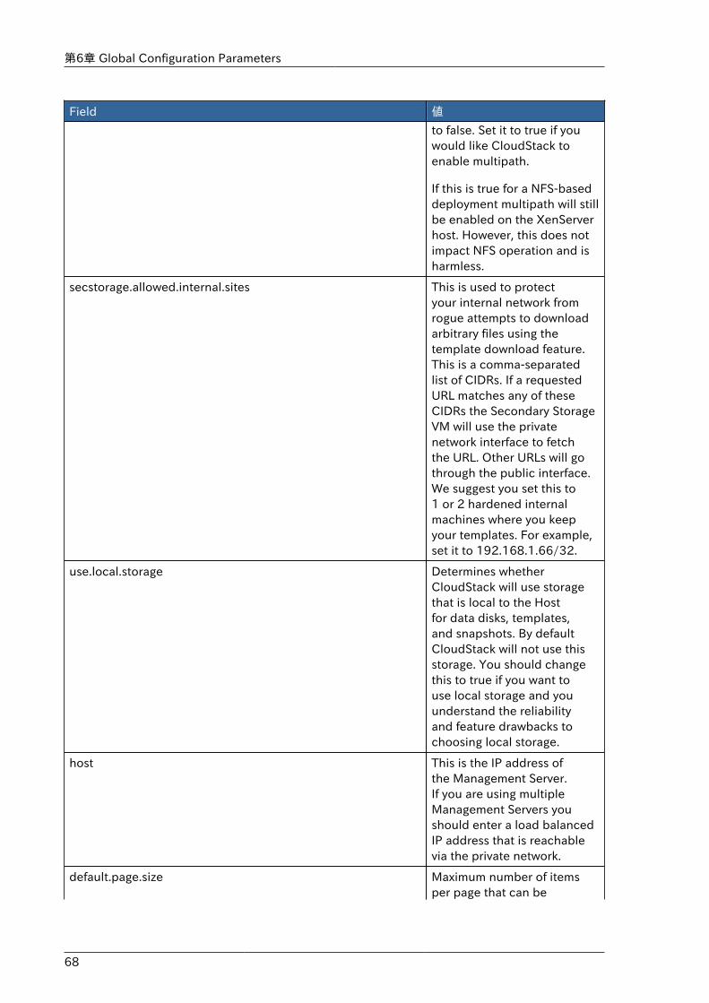
第6章 Global Configuration Parameters
68
Field 値
to false. Set it to true if youwould like CloudStack toenable multipath.
If this is true for a NFS-baseddeployment multipath will stillbe enabled on the XenServerhost. However, this does notimpact NFS operation and isharmless.
secstorage.allowed.internal.sites This is used to protectyour internal network fromrogue attempts to downloadarbitrary files using thetemplate download feature.This is a comma-separatedlist of CIDRs. If a requestedURL matches any of theseCIDRs the Secondary StorageVM will use the privatenetwork interface to fetchthe URL. Other URLs will gothrough the public interface.We suggest you set this to1 or 2 hardened internalmachines where you keepyour templates. For example,set it to 192.168.1.66/32.
use.local.storage Determines whetherCloudStack will use storagethat is local to the Hostfor data disks, templates,and snapshots. By defaultCloudStack will not use thisstorage. You should changethis to true if you want touse local storage and youunderstand the reliabilityand feature drawbacks tochoosing local storage.
host This is the IP address ofthe Management Server.If you are using multipleManagement Servers youshould enter a load balancedIP address that is reachablevia the private network.
default.page.size Maximum number of itemsper page that can be
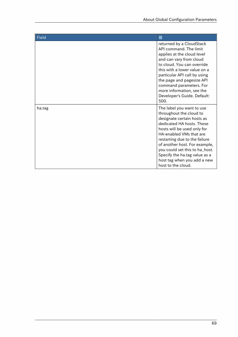
About Global Configuration Parameters
69
Field 値
returned by a CloudStackAPI command. The limitapplies at the cloud leveland can vary from cloudto cloud. You can overridethis with a lower value on aparticular API call by usingthe page and pagesize APIcommand parameters. Formore information, see theDeveloper's Guide. Default:500.
ha.tag The label you want to usethroughout the cloud todesignate certain hosts asdedicated HA hosts. Thesehosts will be used only forHA-enabled VMs that arerestarting due to the failureof another host. For example,you could set this to ha_host.Specify the ha.tag value as ahost tag when you add a newhost to the cloud.

70
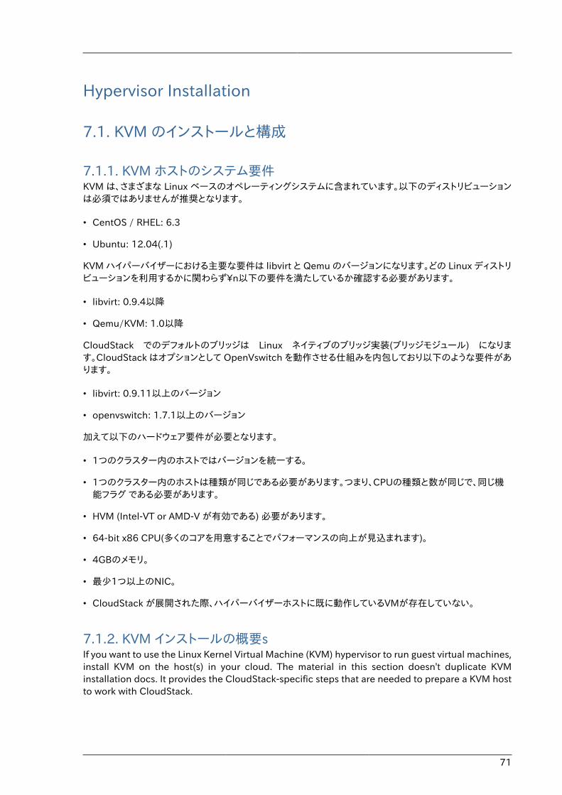
71
Hypervisor Installation
7.1. KVM のインストールと構成
7.1.1. KVM ホストのシステム要件KVM は、さまざまな Linux ベースのオペレーティングシステムに含まれています。以下のディストリビューションは必須ではありませんが推奨となります。
• CentOS / RHEL: 6.3
• Ubuntu: 12.04(.1)
KVM ハイパーバイザーにおける主要な要件は libvirt と Qemu のバージョンになります。どの Linux ディストリビューションを利用するかに関わらず\n以下の要件を満たしているか確認する必要があります。
• libvirt: 0.9.4以降
• Qemu/KVM: 1.0以降
CloudStack でのデフォルトのブリッジは Linux ネイティブのブリッジ実装(ブリッジモジュール) になります。CloudStack はオプションとして OpenVswitch を動作させる仕組みを内包しており以下のような要件があります。
• libvirt: 0.9.11以上のバージョン
• openvswitch: 1.7.1以上のバージョン
加えて以下のハードウェア要件が必要となります。
• 1つのクラスター内のホストではバージョンを統一する。
• 1つのクラスター内のホストは種類が同じである必要があります。つまり、CPUの種類と数が同じで、同じ機能フラグ である必要があります。
• HVM (Intel-VT or AMD-V が有効である) 必要があります。
• 64-bit x86 CPU(多くのコアを用意することでパフォーマンスの向上が見込まれます)。
• 4GBのメモリ。
• 最少1つ以上のNIC。
• CloudStack が展開された際、ハイパーバイザーホストに既に動作しているVMが存在していない。
7.1.2. KVM インストールの概要sIf you want to use the Linux Kernel Virtual Machine (KVM) hypervisor to run guest virtual machines,install KVM on the host(s) in your cloud. The material in this section doesn't duplicate KVMinstallation docs. It provides the CloudStack-specific steps that are needed to prepare a KVM hostto work with CloudStack.
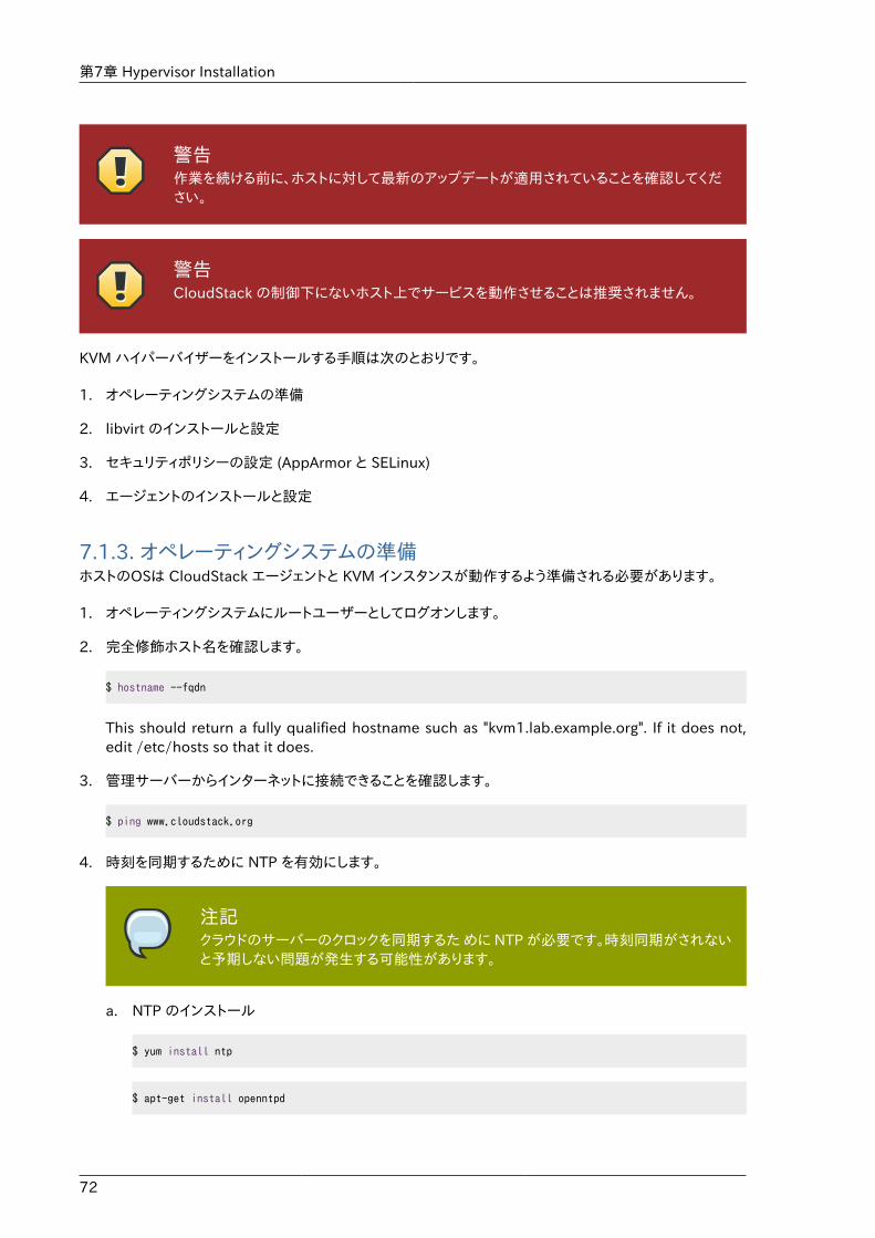
第7章 Hypervisor Installation
72
警告作業を続ける前に、ホストに対して最新のアップデートが適用されていることを確認してください。
警告CloudStack の制御下にないホスト上でサービスを動作させることは推奨されません。
KVM ハイパーバイザーをインストールする手順は次のとおりです。
1. オペレーティングシステムの準備
2. libvirt のインストールと設定
3. セキュリティポリシーの設定 (AppArmor と SELinux)
4. エージェントのインストールと設定
7.1.3. オペレーティングシステムの準備ホストのOSは CloudStack エージェントと KVM インスタンスが動作するよう準備される必要があります。
1. オペレーティングシステムにルートユーザーとしてログオンします。
2. 完全修飾ホスト名を確認します。
$ hostname --fqdn
This should return a fully qualified hostname such as "kvm1.lab.example.org". If it does not,edit /etc/hosts so that it does.
3. 管理サーバーからインターネットに接続できることを確認します。
$ ping www.cloudstack.org
4. 時刻を同期するために NTP を有効にします。
注記クラウドのサーバーのクロックを同期するた めに NTP が必要です。時刻同期がされないと予期しない問題が発生する可能性があります。
a. NTP のインストール
$ yum install ntp
$ apt-get install openntpd
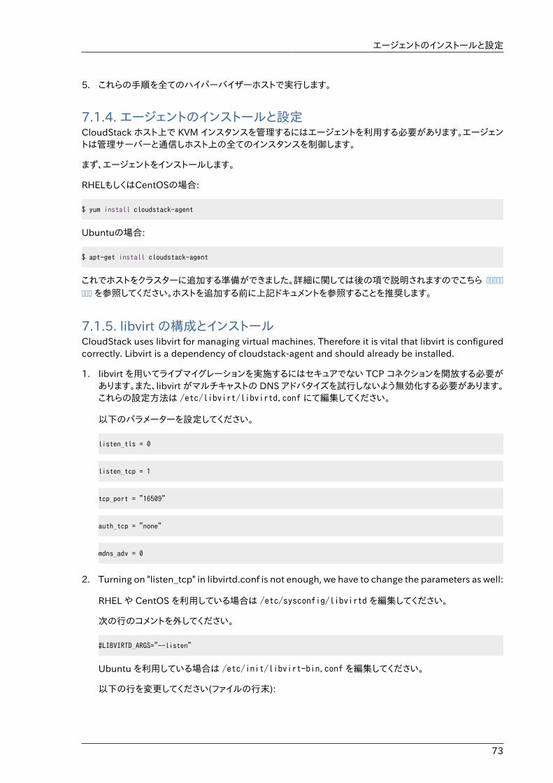
エージェントのインストールと設定
73
5. これらの手順を全てのハイパーバイザーホストで実行します。
7.1.4. エージェントのインストールと設定CloudStack ホスト上で KVM インスタンスを管理するにはエージェントを利用する必要があります。エージェントは管理サーバーと通信しホスト上の全てのインスタンスを制御します。
まず、エージェントをインストールします。
RHELもしくはCentOSの場合:
$ yum install cloudstack-agent
Ubuntuの場合:
$ apt-get install cloudstack-agent
これでホストをクラスターに追加する準備ができました。詳細に関しては後の項で説明されますのでこちら �������� を参照してください。ホストを追加する前に上記ドキュメントを参照することを推奨します。
7.1.5. libvirt の構成とインストールCloudStack uses libvirt for managing virtual machines. Therefore it is vital that libvirt is configuredcorrectly. Libvirt is a dependency of cloudstack-agent and should already be installed.
1. libvirt を用いてライブマイグレーションを実施するにはセキュアでない TCP コネクションを開放する必要があります。また、libvirt がマルチキャストの DNS アドバタイズを試行しないよう無効化する必要があります。これらの設定方法は /etc/libvirt/libvirtd.conf にて編集してください。
以下のパラメーターを設定してください。
listen_tls = 0
listen_tcp = 1
tcp_port = "16509"
auth_tcp = "none"
mdns_adv = 0
2. Turning on "listen_tcp" in libvirtd.conf is not enough, we have to change the parameters as well:
RHEL や CentOS を利用している場合は /etc/sysconfig/libvirtd を編集してください。
次の行のコメントを外してください。
#LIBVIRTD_ARGS="--listen"
Ubuntu を利用している場合は /etc/init/libvirt-bin.conf を編集してください。
以下の行を変更してください(ファイルの行末):
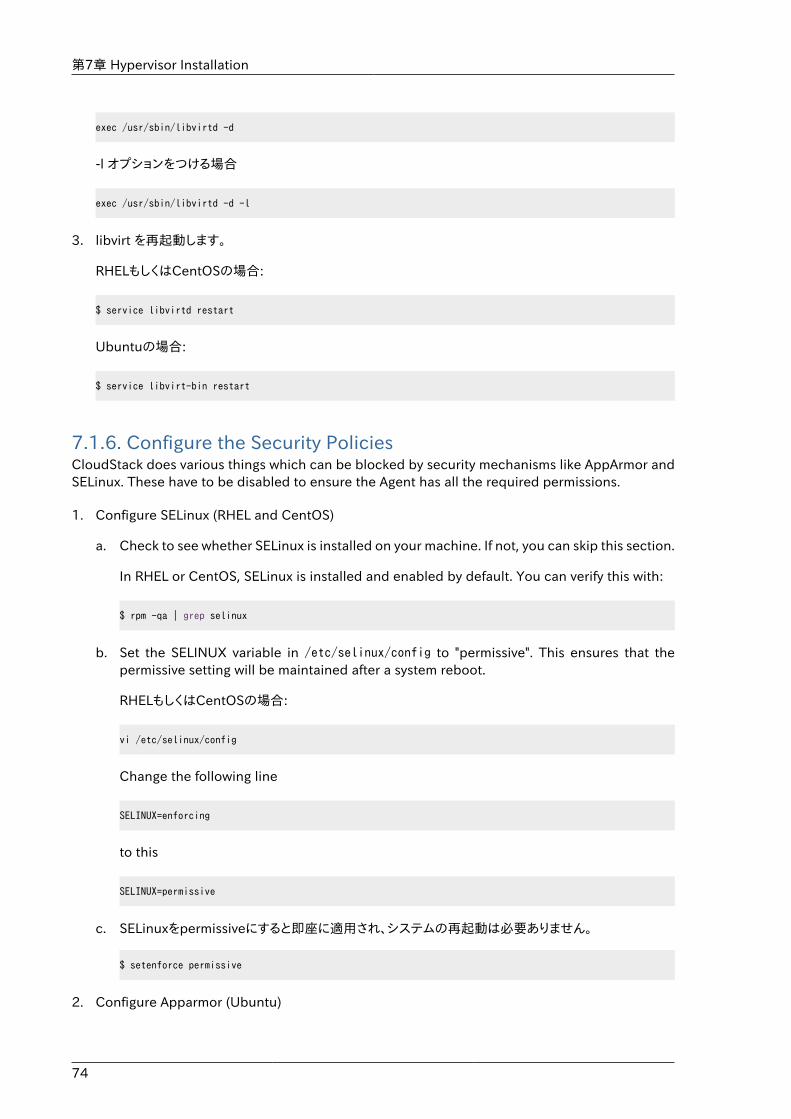
第7章 Hypervisor Installation
74
exec /usr/sbin/libvirtd -d
-l オプションをつける場合
exec /usr/sbin/libvirtd -d -l
3. libvirt を再起動します。
RHELもしくはCentOSの場合:
$ service libvirtd restart
Ubuntuの場合:
$ service libvirt-bin restart
7.1.6. Configure the Security PoliciesCloudStack does various things which can be blocked by security mechanisms like AppArmor andSELinux. These have to be disabled to ensure the Agent has all the required permissions.
1. Configure SELinux (RHEL and CentOS)
a. Check to see whether SELinux is installed on your machine. If not, you can skip this section.
In RHEL or CentOS, SELinux is installed and enabled by default. You can verify this with:
$ rpm -qa | grep selinux
b. Set the SELINUX variable in /etc/selinux/config to "permissive". This ensures that thepermissive setting will be maintained after a system reboot.
RHELもしくはCentOSの場合:
vi /etc/selinux/config
Change the following line
SELINUX=enforcing
to this
SELINUX=permissive
c. SELinuxをpermissiveにすると即座に適用され、システムの再起動は必要ありません。
$ setenforce permissive
2. Configure Apparmor (Ubuntu)
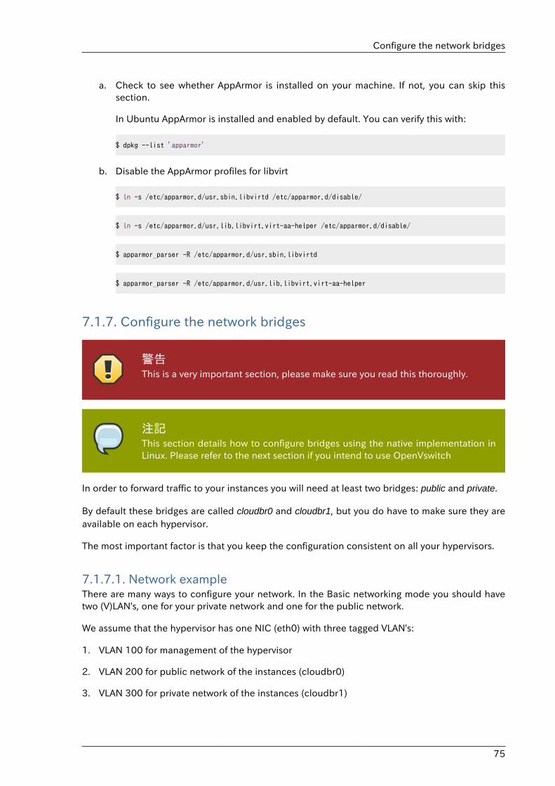
Configure the network bridges
75
a. Check to see whether AppArmor is installed on your machine. If not, you can skip thissection.
In Ubuntu AppArmor is installed and enabled by default. You can verify this with:
$ dpkg --list 'apparmor'
b. Disable the AppArmor profiles for libvirt
$ ln -s /etc/apparmor.d/usr.sbin.libvirtd /etc/apparmor.d/disable/
$ ln -s /etc/apparmor.d/usr.lib.libvirt.virt-aa-helper /etc/apparmor.d/disable/
$ apparmor_parser -R /etc/apparmor.d/usr.sbin.libvirtd
$ apparmor_parser -R /etc/apparmor.d/usr.lib.libvirt.virt-aa-helper
7.1.7. Configure the network bridges
警告This is a very important section, please make sure you read this thoroughly.
注記This section details how to configure bridges using the native implementation inLinux. Please refer to the next section if you intend to use OpenVswitch
In order to forward traffic to your instances you will need at least two bridges: public and private.
By default these bridges are called cloudbr0 and cloudbr1, but you do have to make sure they areavailable on each hypervisor.
The most important factor is that you keep the configuration consistent on all your hypervisors.
7.1.7.1. Network exampleThere are many ways to configure your network. In the Basic networking mode you should havetwo (V)LAN's, one for your private network and one for the public network.
We assume that the hypervisor has one NIC (eth0) with three tagged VLAN's:
1. VLAN 100 for management of the hypervisor
2. VLAN 200 for public network of the instances (cloudbr0)
3. VLAN 300 for private network of the instances (cloudbr1)
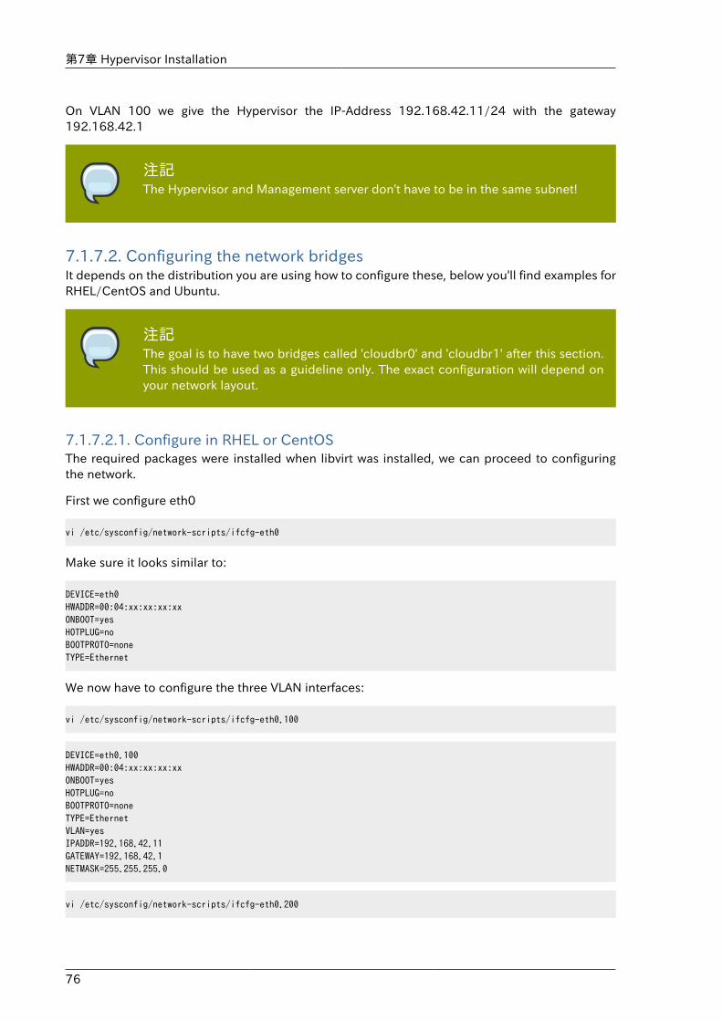
第7章 Hypervisor Installation
76
On VLAN 100 we give the Hypervisor the IP-Address 192.168.42.11/24 with the gateway192.168.42.1
注記The Hypervisor and Management server don't have to be in the same subnet!
7.1.7.2. Configuring the network bridgesIt depends on the distribution you are using how to configure these, below you'll find examples forRHEL/CentOS and Ubuntu.
注記The goal is to have two bridges called 'cloudbr0' and 'cloudbr1' after this section.This should be used as a guideline only. The exact configuration will depend onyour network layout.
7.1.7.2.1. Configure in RHEL or CentOSThe required packages were installed when libvirt was installed, we can proceed to configuringthe network.
First we configure eth0
vi /etc/sysconfig/network-scripts/ifcfg-eth0
Make sure it looks similar to:
DEVICE=eth0HWADDR=00:04:xx:xx:xx:xxONBOOT=yesHOTPLUG=noBOOTPROTO=noneTYPE=Ethernet
We now have to configure the three VLAN interfaces:
vi /etc/sysconfig/network-scripts/ifcfg-eth0.100
DEVICE=eth0.100HWADDR=00:04:xx:xx:xx:xxONBOOT=yesHOTPLUG=noBOOTPROTO=noneTYPE=EthernetVLAN=yesIPADDR=192.168.42.11GATEWAY=192.168.42.1NETMASK=255.255.255.0
vi /etc/sysconfig/network-scripts/ifcfg-eth0.200
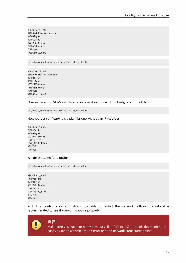
Configure the network bridges
77
DEVICE=eth0.200HWADDR=00:04:xx:xx:xx:xxONBOOT=yesHOTPLUG=noBOOTPROTO=noneTYPE=EthernetVLAN=yesBRIDGE=cloudbr0
vi /etc/sysconfig/network-scripts/ifcfg-eth0.300
DEVICE=eth0.300HWADDR=00:04:xx:xx:xx:xxONBOOT=yesHOTPLUG=noBOOTPROTO=noneTYPE=EthernetVLAN=yesBRIDGE=cloudbr1
Now we have the VLAN interfaces configured we can add the bridges on top of them.
vi /etc/sysconfig/network-scripts/ifcfg-cloudbr0
Now we just configure it is a plain bridge without an IP-Address
DEVICE=cloudbr0TYPE=BridgeONBOOT=yesBOOTPROTO=noneIPV6INIT=noIPV6_AUTOCONF=noDELAY=5STP=yes
We do the same for cloudbr1
vi /etc/sysconfig/network-scripts/ifcfg-cloudbr1
DEVICE=cloudbr1TYPE=BridgeONBOOT=yesBOOTPROTO=noneIPV6INIT=noIPV6_AUTOCONF=noDELAY=5STP=yes
With this configuration you should be able to restart the network, although a reboot isrecommended to see if everything works properly.
警告Make sure you have an alternative way like IPMI or ILO to reach the machine incase you made a configuration error and the network stops functioning!
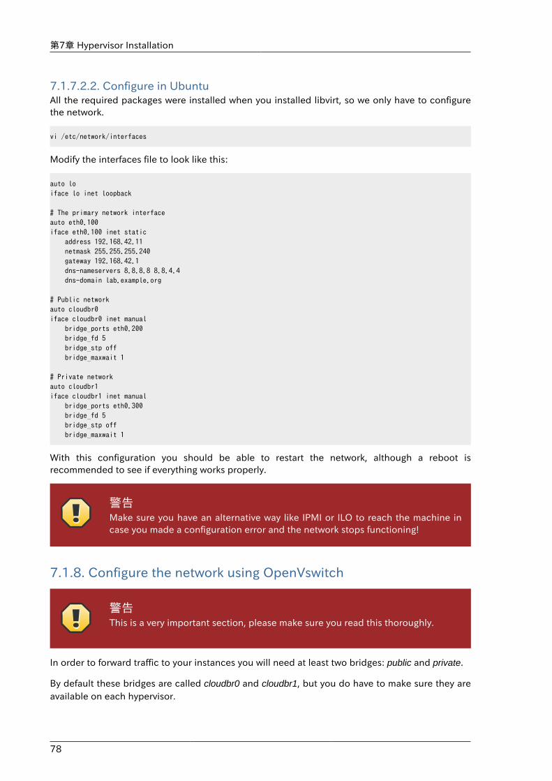
第7章 Hypervisor Installation
78
7.1.7.2.2. Configure in UbuntuAll the required packages were installed when you installed libvirt, so we only have to configurethe network.
vi /etc/network/interfaces
Modify the interfaces file to look like this:
auto loiface lo inet loopback
# The primary network interfaceauto eth0.100iface eth0.100 inet static address 192.168.42.11 netmask 255.255.255.240 gateway 192.168.42.1 dns-nameservers 8.8.8.8 8.8.4.4 dns-domain lab.example.org
# Public networkauto cloudbr0iface cloudbr0 inet manual bridge_ports eth0.200 bridge_fd 5 bridge_stp off bridge_maxwait 1
# Private networkauto cloudbr1iface cloudbr1 inet manual bridge_ports eth0.300 bridge_fd 5 bridge_stp off bridge_maxwait 1
With this configuration you should be able to restart the network, although a reboot isrecommended to see if everything works properly.
警告Make sure you have an alternative way like IPMI or ILO to reach the machine incase you made a configuration error and the network stops functioning!
7.1.8. Configure the network using OpenVswitch
警告This is a very important section, please make sure you read this thoroughly.
In order to forward traffic to your instances you will need at least two bridges: public and private.
By default these bridges are called cloudbr0 and cloudbr1, but you do have to make sure they areavailable on each hypervisor.
Configure the network using OpenVswitch
79
The most important factor is that you keep the configuration consistent on all your hypervisors.
7.1.8.1. PreparingTo make sure that the native bridge module will not interfere with openvswitch the bridge moduleshould be added to the blacklist. See the modprobe documentation for your distribution on whereto find the blacklist. Make sure the module is not loaded either by rebooting or executing rmmodbridge before executing next steps.
The network configurations below depend on the ifup-ovs and ifdown-ovs scripts which are part ofthe openvswitch installation. They should be installed in /etc/sysconfig/network-scripts/
7.1.8.2. Network exampleThere are many ways to configure your network. In the Basic networking mode you should havetwo (V)LAN's, one for your private network and one for the public network.
We assume that the hypervisor has one NIC (eth0) with three tagged VLAN's:
1. VLAN 100 for management of the hypervisor
2. VLAN 200 for public network of the instances (cloudbr0)
3. VLAN 300 for private network of the instances (cloudbr1)
On VLAN 100 we give the Hypervisor the IP-Address 192.168.42.11/24 with the gateway192.168.42.1
注記The Hypervisor and Management server don't have to be in the same subnet!
7.1.8.3. Configuring the network bridgesIt depends on the distribution you are using how to configure these, below you'll find examplesfor RHEL/CentOS.
注記The goal is to have three bridges called 'mgmt0', 'cloudbr0' and 'cloudbr1' afterthis section. This should be used as a guideline only. The exact configuration willdepend on your network layout.
7.1.8.3.1. Configure OpenVswitchThe network interfaces using OpenVswitch are created using the ovs-vsctl command. Thiscommand will configure the interfaces and persist them to the OpenVswitch database.
First we create a main bridge connected to the eth0 interface. Next we create three fake bridges,each connected to a specific vlan tag.
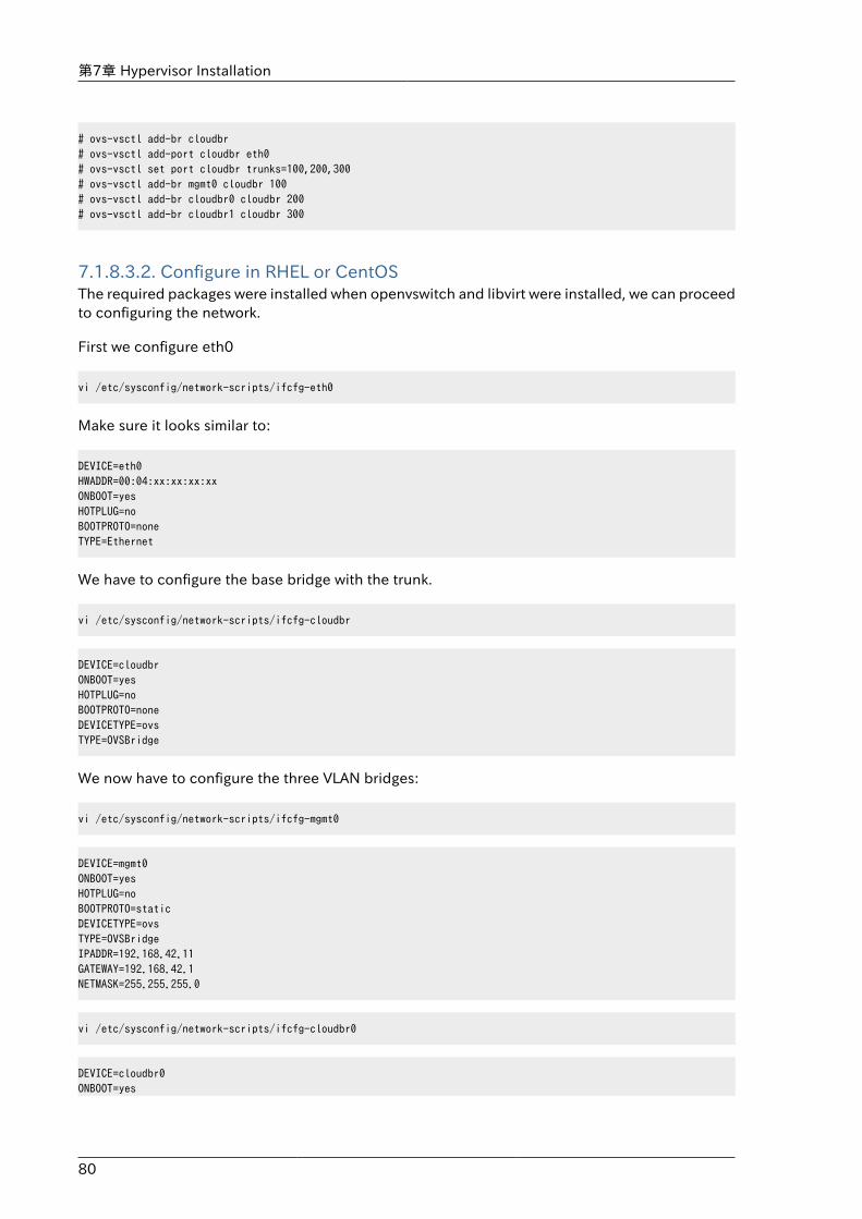
第7章 Hypervisor Installation
80
# ovs-vsctl add-br cloudbr# ovs-vsctl add-port cloudbr eth0 # ovs-vsctl set port cloudbr trunks=100,200,300# ovs-vsctl add-br mgmt0 cloudbr 100# ovs-vsctl add-br cloudbr0 cloudbr 200# ovs-vsctl add-br cloudbr1 cloudbr 300
7.1.8.3.2. Configure in RHEL or CentOSThe required packages were installed when openvswitch and libvirt were installed, we can proceedto configuring the network.
First we configure eth0
vi /etc/sysconfig/network-scripts/ifcfg-eth0
Make sure it looks similar to:
DEVICE=eth0HWADDR=00:04:xx:xx:xx:xxONBOOT=yesHOTPLUG=noBOOTPROTO=noneTYPE=Ethernet
We have to configure the base bridge with the trunk.
vi /etc/sysconfig/network-scripts/ifcfg-cloudbr
DEVICE=cloudbrONBOOT=yesHOTPLUG=noBOOTPROTO=noneDEVICETYPE=ovsTYPE=OVSBridge
We now have to configure the three VLAN bridges:
vi /etc/sysconfig/network-scripts/ifcfg-mgmt0
DEVICE=mgmt0ONBOOT=yesHOTPLUG=noBOOTPROTO=staticDEVICETYPE=ovsTYPE=OVSBridgeIPADDR=192.168.42.11GATEWAY=192.168.42.1NETMASK=255.255.255.0
vi /etc/sysconfig/network-scripts/ifcfg-cloudbr0
DEVICE=cloudbr0ONBOOT=yes
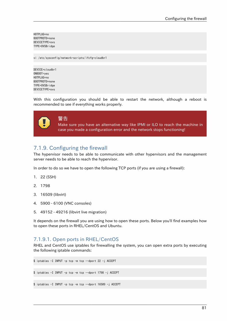
Configuring the firewall
81
HOTPLUG=noBOOTPROTO=noneDEVICETYPE=ovsTYPE=OVSBridge
vi /etc/sysconfig/network-scripts/ifcfg-cloudbr1
DEVICE=cloudbr1ONBOOT=yesHOTPLUG=noBOOTPROTO=noneTYPE=OVSBridgeDEVICETYPE=ovs
With this configuration you should be able to restart the network, although a reboot isrecommended to see if everything works properly.
警告Make sure you have an alternative way like IPMI or ILO to reach the machine incase you made a configuration error and the network stops functioning!
7.1.9. Configuring the firewallThe hypervisor needs to be able to communicate with other hypervisors and the managementserver needs to be able to reach the hypervisor.
In order to do so we have to open the following TCP ports (if you are using a firewall):
1. 22 (SSH)
2. 1798
3. 16509 (libvirt)
4. 5900 - 6100 (VNC consoles)
5. 49152 - 49216 (libvirt live migration)
It depends on the firewall you are using how to open these ports. Below you'll find examples howto open these ports in RHEL/CentOS and Ubuntu.
7.1.9.1. Open ports in RHEL/CentOSRHEL and CentOS use iptables for firewalling the system, you can open extra ports by executingthe following iptable commands:
$ iptables -I INPUT -p tcp -m tcp --dport 22 -j ACCEPT
$ iptables -I INPUT -p tcp -m tcp --dport 1798 -j ACCEPT
$ iptables -I INPUT -p tcp -m tcp --dport 16509 -j ACCEPT
第7章 Hypervisor Installation
82
$ iptables -I INPUT -p tcp -m tcp --dport 5900:6100 -j ACCEPT
$ iptables -I INPUT -p tcp -m tcp --dport 49152:49216 -j ACCEPT
These iptable settings are not persistent accross reboots, we have to save them first.
$ iptables-save > /etc/sysconfig/iptables
7.1.9.2. Open ports in UbuntuThe default firewall under Ubuntu is UFW (Uncomplicated FireWall), which is a Python wrapperaround iptables.
To open the required ports, execute the following commands:
$ ufw allow proto tcp from any to any port 22
$ ufw allow proto tcp from any to any port 1798
$ ufw allow proto tcp from any to any port 16509
$ ufw allow proto tcp from any to any port 5900:6100
$ ufw allow proto tcp from any to any port 49152:49216
注記By default UFW is not enabled on Ubuntu. Executing these commands with thefirewall disabled does not enable the firewall.
7.1.10. CloudStack へのホスト追加これでホストをクラスターに追加する準備ができました。詳細に関しては後の項で説明されますのでこちら �������� を参照してください。ホストを追加する前に上記ドキュメントを参照することを推奨します。
7.2. CloudStackのためのCitrix XenServerのインストールCitrix XenServer ハイパーバイザーを使用してゲスト仮想マシンを実行する場合は、XenServer 6.0 もしくはXenServer 6.0.2 をクラウド内のホストにインストールします。初回インストールの場合は、 次の手順に従ってください。XenServer をインストール済みで、別のバージョンにアップグレードする場合は、�XenServer �������������� を参照してください。
7.2.1. XenServerホストのシステム要件• ホストは 次に示す互換性のいづれかを認定されている必要があります。 http://hcl.xensource.com の
『Citrix Hardware Compatibility Guide』を参照してください。
• XenServer 5.6 SP2
XenServerのインストール手順
83
• XenServer 6.0
• XenServer 6.0.2
• 前にインストールしたホストを再使用する場合は、Citrix XenServer を再インストールする必要があります。
• ハードウェア仮想マシン(Intel-VTまたはAMD-Vが有効であること)をサポート する必要があります。
• ハイパーバイザーの製造元が提供するすべての Hotfix を適用 したことを確認します。ハイパーバイザーの製造元のサポートチャネルを通じてパッチのリリース状況を確認し、パッチがリリースされたらできるだけ早く適用します。ハイパーバイザーの必須パッチについて CloudStack が自動的に通知することはありません。ホストにハイパーバイザーの最新パッチを適用する ことは非常に重要です。最新パッチが適用されていないシステムは、おそらくハイパーバイザーの製造元からサポートを受けられません。
• クラスター内にあるホストは全て同スペックでなければいけません。CPU の種類や数、機能フラグが同じでなければいけません。
• ハードウェア仮想マシン(Intel-VTまたはAMD-VがBIOSで有効であること)をサポート する必要があります。
• 64-bit x86 CPU(多くのコアを用意することでパフォーマンスの向上が見込まれます)
• 完全仮想化のサポートが必要。
• 4GBのメモリ
• 36 GBのローカルディスク
• 最少1つ以上のNIC
• 静的IPアドレス
• CloudStack が展開された際、ハイパーバイザーホストに既に動作しているVMが存在していない。
警告最新の Hotfix を適用しないと、データの破損や仮想マシンの喪失が生じる可能性があります。
7.2.2. XenServerのインストール手順1. Citrix 社の Web サイト(https://www.citrix.com/English/ss/downloads/)から あなたの
CloudStack のバージョンに合った XenServer をダウンロードし、『Citrix XenServer インストールガイド』に従ってインス トールします。
2. インストール後、次の手順に従い設定を行います。
必須 オプション
�XenServer ����0������� �CloudStack XenServer SupportPakcage(CSP)��������
������������� iSCSIやローカルディスク、NFSを利用しない場合SRをセットアップします。詳細は�XenServer ��������������������を参照してください。
第7章 Hypervisor Installation
84
必須 オプション
������ �XenServer � iSCSI ������������(�����)�
������������� �XenServer ������������
7.2.3. XenServer ドメイン0のメモリ設定XenServer の dom0 へのメモリ割り当てを増やすために、dom0 の設定を構成します。これにより、XenServer でより多くの仮想マシンを制御できるようになります。XenServer の dom0 に 2940MBの RAM を割り当てることをお勧めします。この方法について詳しくは、http://support.citrix.com/article/CTX126531 を参照してください。 このアーティクルで言及されているのは XenServer 5.6 ですが、同じことがXenServer 6.0 にも当てはまります。
7.2.4. ユーザー名とパスワードクラスター内のすべての XenServer に、CloudStack に構成されたものと同じユーザー名およびパスワードが必要です。
7.2.5. 時刻同期ホストはNTPを使用する必要があります。ポッド内のすべてのホストは時刻が同期される必要があります。
1. NTPのインストール
# yum install ntp
2. 使用する NTP サーバーを参照するように、NTP 構成ファイ ルを編集します。
# vi /etc/ntp.conf
使用する NTP サーバーを参照するように、NTP 構成ファイルを編集します。例として Citrix が提供する次の NTP サーバーを使用できます。
server 0.xenserver.pool.ntp.orgserver 1.xenserver.pool.ntp.orgserver 2.xenserver.pool.ntp.orgserver 3.xenserver.pool.ntp.org
3. NTPクライアントの再起動
# service ntpd restart
4. 再起動時に NTP が再び開始されることを確認します。
# chkconfig ntpd on
7.2.6. ライセンス設定無償版の Citrix XenServer は、ライセンスなしで 30 日間使用できます。30 日の試用期間を過ぎると、無償のライセンス認 証が要求されます。ここでライセンスをインストールするか、この手順を省略するかを選
CloudStack XenServer Support Pakcage(CSP)のインストール
85
択できます。この手順を省略する場合は、XenServer をアクティブ化してライセンスを有効にするときに、ライセンスをインストールする必要があります。
7.2.6.1. ライセンスの取得と展開ここでライセンスをインストールする場合は、XenCenter を使用して、ライセンスをアクティブ化して取得する必要がありま す。
1. In XenCenter, click Tools > License manager.
2. XenServer を選択し、[無償の XenServer のアクティブ化]を選択します。
3. ライセンスを要求します。
XenCenter または xe コマンドラインツールを使用して、ライセンスをインストールできます。
7.2.7. CloudStack XenServer Support Pakcage(CSP)のインストール(オプション)
XenServer でセキュリティグループ、エラスティック負荷分散、およびエラスティック IP を有効にするには、CloudStack XenServer Support Package(CSP)をダウンロードしてインストールします。XenServer をインストールしたら、各 XenServer ホストで次の追加手順を実行します。
1. 次のリンクのどちらかから XenServer ホストに CSP ソフトウェアをダウンロードします。
XenServer 6.0.2 の場合:
http://download.cloud.com/releases/3.0.1/XS-6.0.2/xenserver-cloud-supp.tgz
XenServer 5.6 SP2 の場合:
http://download.cloud.com/releases/2.2.0/xenserver-cloud-supp.tgz
XenServer 6.0 の場合:
http://download.cloud.com/releases/3.0/xenserver-cloud-supp.tgz
2. ファイルの展開:
# tar xf xenserver-cloud-supp.tgz
3. 以下スクリプトの実行:
# xe-install-supplemental-pack xenserver-cloud-supp.iso
4. XenServer ホストが基本ネットワーク設定を使用するゾーンの一部である場合は、Open vSwitch(OVS)を無効にし ます。
# xe-switch-network-backend bridge
再起動を促すメッセージが表示されたら、再起動を受け入れます。
これで、XenServer ホストを CloudStack に追加する準備ができました。
第7章 Hypervisor Installation
86
7.2.8. XenServer 用のプライマリストレージのセットアップCloudStack natively supports NFS, iSCSI and local storage. If you are using one of these storagetypes, there is no need to create the XenServer Storage Repository ("SR").
ただし、ファイバーチャネルなどのほかの技術を介して接続されたストレージを使用する場合は、ストレージリポジトリを自分でセットアップする必要があります。これを行うには、次の手順に従います。XenServer プールにホストがある場合は、マスターノードで手順を実行します。クラスター化されていない単一の XenServer を使用する場合は、その XenServer で手順 を実行します。
1. ファイバーチャネルケーブルをクラスター内のすべてのホストとファイバーチャネルストレージホストに接続します。
2. SCSI バスを再スキャンします。次のコマンドまたは XenCenter を使用して、HBA 再スキャンを実行します。
# scsi-rescan
3. 2 の手順を各ホスト上で繰り返します。
4. 新しいSCSIディスクを確認します。
# ls /dev/disk/by-id/scsi-360a98000503365344e6f6177615a516b -l
The output should look like this, although the specific file name will be different (scsi-<scsiID>):
lrwxrwxrwx 1 root root 9 Mar 16 13:47/dev/disk/by-id/scsi-360a98000503365344e6f6177615a516b -> ../../sdc
5. 4 の手順を各ホスト上で繰り返します。
6. ストレージサーバーで次のコマンドを実行し、新しいストレージリポジトリの固有の ID を取得します。
# uuidgen
出力は次のようになりますが、具体的な ID は異なります。
e6849e96-86c3-4f2c-8fcc-350cc711be3d
7. ファイバーチャネルのストレージリポジトリを作成します。名前ラベルには、生成した固有の ID を使用します。
# xe sr-create type=lvmohba shared=truedevice-config:SCSIid=360a98000503365344e6f6177615a516bname-label="e6849e96-86c3-4f2c-8fcc-350cc711be3d"
このコマンドは、次の例のようにストレージリポジトリの固有の ID を戻します(実際の ID は異なります)。
7a143820-e893-6c6a-236e-472da6ee66bf
XenServer の iSCSI マルチパスのセットアップ(オプション)
87
8. ストレージリポジトリについて人間が読める説明を作成するには、次のコマンドを使用します。UUID には、前のコマ ンドで戻されたストレージリポジトリ ID を使用します。名前の説明には、好みに合わせてわかりやすいテキストを設 定します。
# xe sr-param-set uuid=7a143820-e893-6c6a-236e-472da6ee66bf name-description="Fiber Channel storage repository"
このストレージを後で CloudStack に追加するときに必要な値を控えておきます( ���������������を参照)。[プライマリストレージの追加]ダイアログボックスの[プロトコル]ボックスの一覧で、[事前セットアップ]を選択しま す。[ストレージレポジトリ名前ラベル]ボックスには、前に設定した名前ラベルを入力します(この例では、 e6849e96-86c3-4f2c-8fcc-350cc711be3d)。
9. (オプション)ファイバーチャネル SAN でマルチパス I/O を有効にする場合は、SAN の製造元が提供するドキュメントを参照してください。
7.2.9. XenServer の iSCSI マルチパスのセットアップ(オプション)Citrix XenServer でストレージリポジトリをセットアップするとき、マルチパス I/O を有効にできます。マルチパス I/O を使用すると、冗長な物理コンポーネントを使用してサーバーと SAN の接続の信頼性を高めることができます。マルチパスを有効にするには、Citrix サーバーでサポートされる SAN ソリューションを使用し、Citrix ドキュメントに記載されている手順に従います。基本情報については、次のリンクを参照してください。
• http://support.citrix.com/article/CTX118791
• http://support.citrix.com/article/CTX125403
マルチパスを使用した Citrix リポジトリのセットアップについて、SAN の製造元に助言を求めることもできます。
このストレージを後で CloudStack に追加するときに必要な値を控えておきます( ���������������を参照)。[プライマリストレージの追加]ダイアログボックスの[プロトコル]ボックスの一覧で、[事前セットアップ]を選択します。[ストレージレポジトリ名前ラベル]ボックスには、ストレージリポジトリの作成に使用した名前と同じものを入力します。
問題が発生した場合は、SAN の製造元のサポート部門に問い合わせてください。問題が解決できない場合は、「サポート への問い合わせ」を参照してください。
7.2.10. XenServer の物理ネットワーク設定XenServer をインストールした後で、追加のネットワーク構成が必要な場合があります。この時点で、ホストのNIC の種類と 各 NIC が伝送するトラフィックについて、計画済みである必要があります。NIC は、計画に合わせて配線する必要がありま す。
NIC ボンディングを使用する場合は、クラスター内のすべてのホスト上の NIC を完全に同じ配線にする必要があります。例えば、eth0 がクラスター内のあるホスト上のプライベートボンドにある場合、eth0 はクラスター内のすべてのホストでプライベートボンドに存在する必要があります。
管理ネットワークインターフェイス用に割り当てる IP アドレスは、静的である必要があります。この IP アドレスはホスト自体で設定したり、静的 DHCP 経由で取得したりできます。
CloudStack では、XenServer ホストでさまざまな NIC またはボンドを使用できるように、各種のネットワークトラフィックが構成されます。XenServer のネットワーク名ラベルを使用して、このプロセスを制御し、管理サーバーに情報を提供できます。 CloudStack で名前ラベルを物理インターフェイスまたはボンドに付けて構成します。簡単な構成の場合は、名前ラベルは必要ありません。
第7章 Hypervisor Installation
88
7.2.10.1. XenServer の専用 NIC を使用したパブリックネットワークの構成(オプション)CloudStack supports the use of a second NIC (or bonded pair of NICs, described in �XenServer �NIC ������(�����)�) for the public network. If bonding is not used, the public network can be on anyNIC and can be on different NICs on the hosts in a cluster. For example, the public network can beon eth0 on node A and eth1 on node B. However, the XenServer name-label for the public networkmust be identical across all hosts. The following examples set the network label to "cloud-public".After the management server is installed and running you must configure it with the name of thechosen network label (e.g. "cloud-public"); this is discussed in ���������������.
ボンドした 2 つの NIC を使用してパブリックネットワークを作成する場合は、�XenServer � NIC ������(�����)�を参照してください。
単一の専用 NIC を使用してパブリックネットワークアクセスを提供する場合は、この手順に従って CloudStackに追加する 各新規ホストを設定してから、ホストを追加します。
1. Run xe network-list and find the public network. This is usually attached to the NIC that ispublic. Once you find the network make note of its UUID. Call this <UUID-Public>.
2. 次のコマンドを実行します。
# xe network-param-set name-label=cloud-public uuid=<UUID-Public>
7.2.10.2. XenServer の複数のゲストネットワークの構成(オプション)CloudStack supports the use of multiple guest networks with the XenServer hypervisor. Eachnetwork is assigned a name-label in XenServer. For example, you might have two networks with thelabels "cloud-guest" and "cloud-guest2". After the management server is installed and running, youmust add the networks and use these labels so that CloudStack is aware of the networks.
この手順に従って各新規ホストを設定してから、CloudStack にホストを追加します。
1. Run xe network-list and find one of the guest networks. Once you find the network make noteof its UUID. Call this <UUID-Guest>.
2. 次のコマンドを実行します。名前ラベルと UUID は実際の値で置き換えます。
# xe network-param-set name-label=<cloud-guestN> uuid=<UUID-Guest>
3. 追加する各ゲストネットワークに対して毎回異なる名前ラベルと UUID を使用して、この手順を繰り返します。
7.2.10.3. XenServer 用の個別のストレージネットワーク(オプション)You can optionally set up a separate storage network. This should be done first on the host, beforeimplementing the bonding steps below. This can be done using one or two available NICs. Withtwo NICs bonding may be done as above. It is the administrator's responsibility to set up a separatestorage network.
ストレージネットワークに、ほかのネットワークとは異なる名前ラベルを指定します。
For the separate storage network to work correctly, it must be the only interface that can ping theprimary storage device's IP address. For example, if eth0 is the management network NIC, ping -
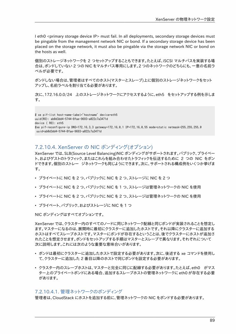
XenServer の物理ネットワーク設定
89
I eth0 <primary storage device IP> must fail. In all deployments, secondary storage devices mustbe pingable from the management network NIC or bond. If a secondary storage device has beenplaced on the storage network, it must also be pingable via the storage network NIC or bond onthe hosts as well.
個別のストレージネットワークを 2 つセットアップすることもできます。たとえば、iSCSI マルチパスを実装する場合は、ボンドしていない 2 つの NIC をマルチパス専用にします。2 つのネットワークのどちらにも、一意の名前ラベルが必要です。
ボンドしない場合は、管理者はすべてのホスト(マスターとスレーブ)上に個別のストレージネットワークをセットアップし、名前ラベルを割り当てる必要があります。
次に、172.16.0.0/24 上のストレージネットワークにアクセスするように、eth5 をセットアップする例を示します。
# xe pif-list host-name-label='hostname' device=eth5uuid(RO): ab0d3dd4-5744-8fae-9693-a022c7a3471ddevice ( RO): eth5#xe pif-reconfigure-ip DNS=172.16.3.3 gateway=172.16.0.1 IP=172.16.0.55 mode=static netmask=255.255.255.0 uuid=ab0d3dd4-5744-8fae-9693-a022c7a3471d
7.2.10.4. XenServer の NIC ボンディング(オプション)XenServer では、SLB(Source Level Balancing)NIC ボンディングがサポートされます。パブリック、プライベート、およびゲストのトラフィック、またはこれらを組み合わせたトラフィックを伝送するために 2 つの NIC をボンドできます。個別のストレー ジネットワークも同じようにできます。次に、サポートされる構成例をいくつか挙げます。
• プライベートに NIC を 2 つ、パブリックに NIC を 2 つ、ストレージに NIC を 2 つ
• プライベートに NIC を 2 つ、パブリックに NIC を 1 つ、ストレージは管理ネットワークの NIC を使用
• プライベートに NIC を 2 つ、パブリックに NIC を 2 つ、ストレージは管理ネットワークの NIC を使用
• プライベート、パブリック、およびストレージに NIC を 1 つ
NIC ボンディングはすべてオプションです。
XenServer では、クラスター内のすべてのノードに同じネットワーク配線と同じボンドが実装されることを想定します。マスターになるのは、展開時に最初にクラスターに追加したホストです。それ以降にクラスターに追加するホストはすべてスレーブホストです。マスターにボンドが存在するということは、後でクラスターにホストが追加されたことを想定させます。ボンドをセットアップする手順はマスターとスレーブで異なります。それぞれについて次に説明します。これには次のような重要な意味合いがあります。
• ボンドは最初にクラスターに追加したホストで設定する必要があります。次に、後述する xe コマンドを使用して、クラスターに追加した 2 番目以降のホストで同じボンドを設定する必要があります。
• クラスター内のスレーブホストは、マスターと完全に同じに配線する必要があります。たとえば、eth0 がマスター上のプライベートボンドにある場合、追加するスレーブホストの管理ネットワークに eth0 が存在する必要があります。
7.2.10.4.1. 管理ネットワークのボンディング管理者は、CloudStack にホストを追加する前に、管理ネットワークの NIC をボンドする必要があります。
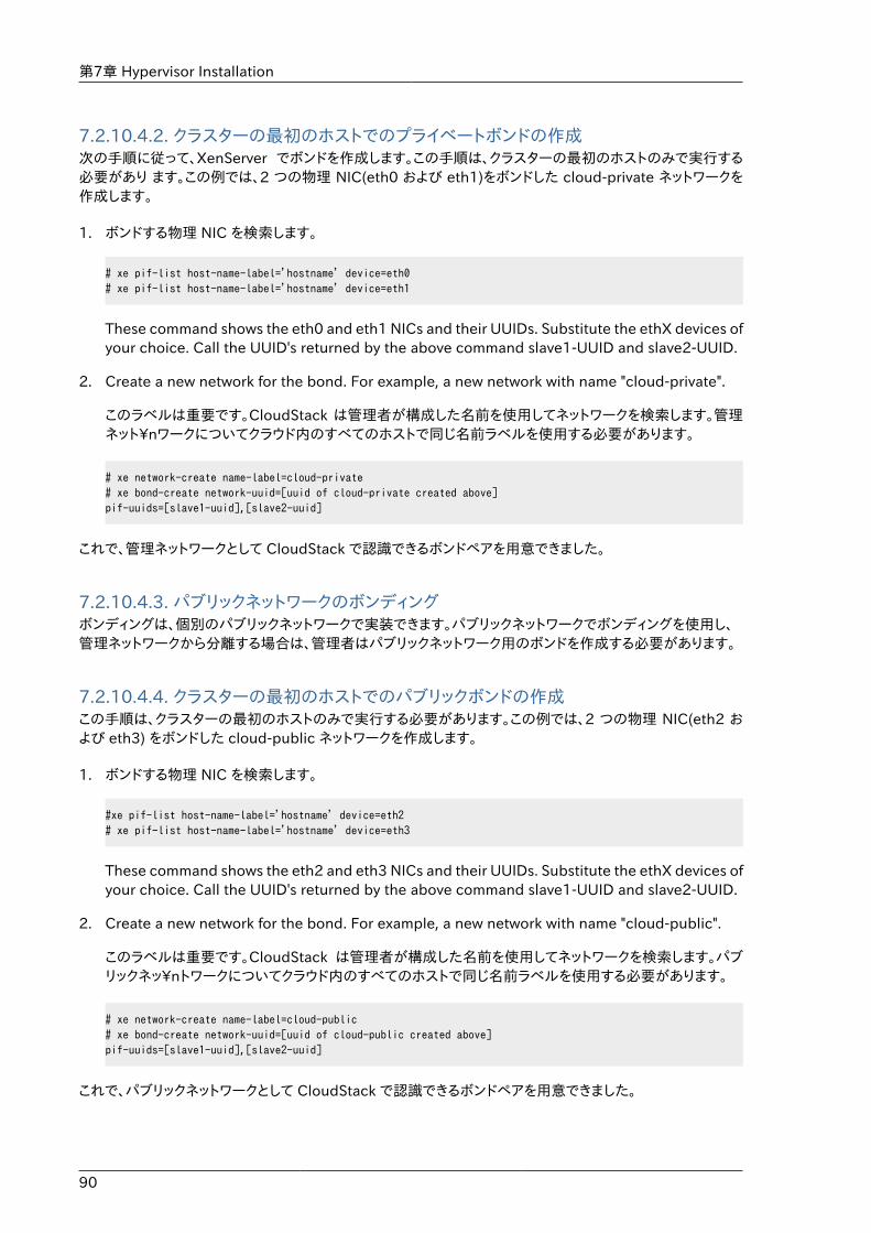
第7章 Hypervisor Installation
90
7.2.10.4.2. クラスターの最初のホストでのプライベートボンドの作成次の手順に従って、XenServer でボンドを作成します。この手順は、クラスターの最初のホストのみで実行する必要があり ます。この例では、2 つの物理 NIC(eth0 および eth1)をボンドした cloud-private ネットワークを作成します。
1. ボンドする物理 NIC を検索します。
# xe pif-list host-name-label='hostname' device=eth0# xe pif-list host-name-label='hostname' device=eth1
These command shows the eth0 and eth1 NICs and their UUIDs. Substitute the ethX devices ofyour choice. Call the UUID's returned by the above command slave1-UUID and slave2-UUID.
2. Create a new network for the bond. For example, a new network with name "cloud-private".
このラベルは重要です。CloudStack は管理者が構成した名前を使用してネットワークを検索します。管理ネット\nワークについてクラウド内のすべてのホストで同じ名前ラベルを使用する必要があります。
# xe network-create name-label=cloud-private# xe bond-create network-uuid=[uuid of cloud-private created above]pif-uuids=[slave1-uuid],[slave2-uuid]
これで、管理ネットワークとして CloudStack で認識できるボンドペアを用意できました。
7.2.10.4.3. パブリックネットワークのボンディングボンディングは、個別のパブリックネットワークで実装できます。パブリックネットワークでボンディングを使用し、管理ネットワークから分離する場合は、管理者はパブリックネットワーク用のボンドを作成する必要があります。
7.2.10.4.4. クラスターの最初のホストでのパブリックボンドの作成この手順は、クラスターの最初のホストのみで実行する必要があります。この例では、2 つの物理 NIC(eth2 および eth3) をボンドした cloud-public ネットワークを作成します。
1. ボンドする物理 NIC を検索します。
#xe pif-list host-name-label='hostname' device=eth2# xe pif-list host-name-label='hostname' device=eth3
These command shows the eth2 and eth3 NICs and their UUIDs. Substitute the ethX devices ofyour choice. Call the UUID's returned by the above command slave1-UUID and slave2-UUID.
2. Create a new network for the bond. For example, a new network with name "cloud-public".
このラベルは重要です。CloudStack は管理者が構成した名前を使用してネットワークを検索します。パブリックネッ\nトワークについてクラウド内のすべてのホストで同じ名前ラベルを使用する必要があります。
# xe network-create name-label=cloud-public# xe bond-create network-uuid=[uuid of cloud-public created above]pif-uuids=[slave1-uuid],[slave2-uuid]
これで、パブリックネットワークとして CloudStack で認識できるボンドペアを用意できました。
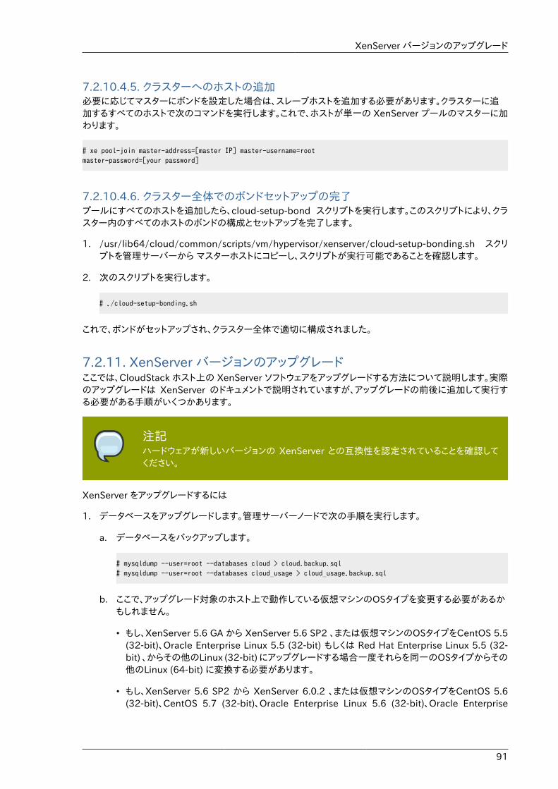
XenServer バージョンのアップグレード
91
7.2.10.4.5. クラスターへのホストの追加必要に応じてマスターにボンドを設定した場合は、スレーブホストを追加する必要があります。クラスターに追加するすべてのホストで次のコマンドを実行します。これで、ホストが単一の XenServer プールのマスターに加わります。
# xe pool-join master-address=[master IP] master-username=rootmaster-password=[your password]
7.2.10.4.6. クラスター全体でのボンドセットアップの完了プールにすべてのホストを追加したら、cloud-setup-bond スクリプトを実行します。このスクリプトにより、クラスター内のすべてのホストのボンドの構成とセットアップを完了します。
1. /usr/lib64/cloud/common/scripts/vm/hypervisor/xenserver/cloud-setup-bonding.sh スクリプトを管理サーバーから マスターホストにコピーし、スクリプトが実行可能であることを確認します。
2. 次のスクリプトを実行します。
# ./cloud-setup-bonding.sh
これで、ボンドがセットアップされ、クラスター全体で適切に構成されました。
7.2.11. XenServer バージョンのアップグレードここでは、CloudStack ホスト上の XenServer ソフトウェアをアップグレードする方法について説明します。実際のアップグレードは XenServer のドキュメントで説明されていますが、アップグレードの前後に追加して実行する必要がある手順がいくつかあります。
注記ハードウェアが新しいバージョンの XenServer との互換性を認定されていることを確認してください。
XenServer をアップグレードするには
1. データベースをアップグレードします。管理サーバーノードで次の手順を実行します。
a. データベースをバックアップします。
# mysqldump --user=root --databases cloud > cloud.backup.sql# mysqldump --user=root --databases cloud_usage > cloud_usage.backup.sql
b. ここで、アップグレード対象のホスト上で動作している仮想マシンのOSタイプを変更する必要があるかもしれません。
• もし、XenServer 5.6 GA から XenServer 5.6 SP2 、または仮想マシンのOSタイプをCentOS 5.5(32-bit)、Oracle Enterprise Linux 5.5 (32-bit) もしくは Red Hat Enterprise Linux 5.5 (32-bit) 、からその他のLinux (32-bit) にアップグレードする場合一度それらを同一のOSタイプからその他のLinux (64-bit) に変換する必要があります。
• もし、XenServer 5.6 SP2 から XenServer 6.0.2 、または仮想マシンのOSタイプをCentOS 5.6(32-bit)、CentOS 5.7 (32-bit)、Oracle Enterprise Linux 5.6 (32-bit)、Oracle Enterprise
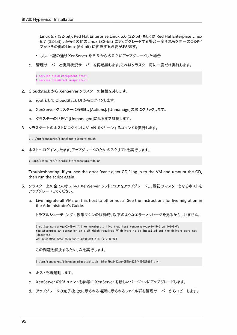
第7章 Hypervisor Installation
92
Linux 5.7 (32-bit)、Red Hat Enterprise Linux 5.6 (32-bit) もしくは Red Hat Enterprise Linux5.7 (32-bit) 、からその他のLinux (32-bit) にアップグレードする場合一度それらを同一のOSタイプからその他のLinux (64-bit) に変換する必要があります。
• もし、上記の通り XenServer を 5.6 から 6.0.2 にアップグレードした場合
c. 管理サーバーと使用状況サーバーを再起動します。これはクラスター毎に一度だけ実施します。
# service cloud-management start# service cloudstack-usage start
2. CloudStack から XenServer クラスターの接続を外します。
a. root として CloudStack UI からログインします。
b. XenServer クラスターに移動し、[Actions]、[Unmanage]の順にクリックします。
c. クラスターの状態が[Unmanaged]になるまで監視します。
3. クラスター上のホストにログインし、VLAN をクリーンするコマンドを実行します。
# . /opt/xensource/bin/cloud-clean-vlan.sh
4. ホストへログインしたまま、アップグレードのためのスクリプトを実行します。
# /opt/xensource/bin/cloud-prepare-upgrade.sh
Troubleshooting: If you see the error "can't eject CD," log in to the VM and umount the CD,then run the script again.
5. クラスター上の全てのホストの XenServer ソフトウェアをアップグレードし、最初のマスターとなるホストをアップグレードしてください。
a. Live migrate all VMs on this host to other hosts. See the instructions for live migration inthe Administrator's Guide.
トラブルシューティング : 仮想マシンの移動時、以下のようなエラーメッセージを見るかもしれません。
[root@xenserver-qa-2-49-4 ~]# xe vm-migrate live=true host=xenserver-qa-2-49-5 vm=i-2-8-VMYou attempted an operation on a VM which requires PV drivers to be installed but the drivers were not detected.vm: b6cf79c8-02ee-050b-922f-49583d9f1a14 (i-2-8-VM)
この問題を解決するため、次を実行します。
# /opt/xensource/bin/make_migratable.sh b6cf79c8-02ee-050b-922f-49583d9f1a14
b. ホストを再起動します。
c. XenServer のドキュメントを参考に XenServer を新しいバージョンにアップグレードします。
d. アップグレードの完了後、次に示される場所に示されるファイル群を管理サーバーからコピーします。
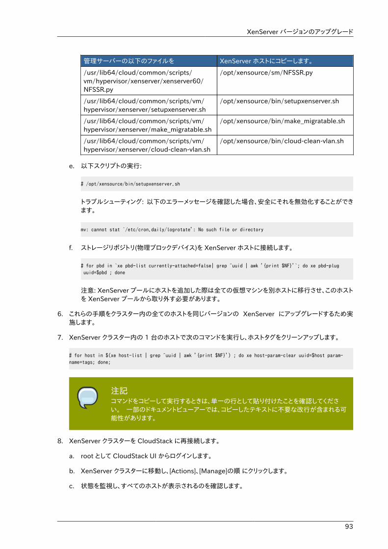
XenServer バージョンのアップグレード
93
管理サーバーの以下のファイルを XenServer ホストにコピーします。
/usr/lib64/cloud/common/scripts/vm/hypervisor/xenserver/xenserver60/NFSSR.py
/opt/xensource/sm/NFSSR.py
/usr/lib64/cloud/common/scripts/vm/hypervisor/xenserver/setupxenserver.sh
/opt/xensource/bin/setupxenserver.sh
/usr/lib64/cloud/common/scripts/vm/hypervisor/xenserver/make_migratable.sh
/opt/xensource/bin/make_migratable.sh
/usr/lib64/cloud/common/scripts/vm/hypervisor/xenserver/cloud-clean-vlan.sh
/opt/xensource/bin/cloud-clean-vlan.sh
e. 以下スクリプトの実行:
# /opt/xensource/bin/setupxenserver.sh
トラブルシューティング: 以下のエラーメッセージを確認した場合、安全にそれを無効化することができます。
mv: cannot stat `/etc/cron.daily/logrotate': No such file or directory
f. ストレージリポジトリ(物理ブロックデバイス)を XenServer ホストに接続します。
# for pbd in `xe pbd-list currently-attached=false| grep ^uuid | awk '{print $NF}'`; do xe pbd-plug uuid=$pbd ; done
注意: XenServer プールにホストを追加した際は全ての仮想マシンを別ホストに移行させ、このホストを XenServer プールから取り外す必要があります。
6. これらの手順をクラスター内の全てのホストを同じバージョンの XenServer にアップグレードするため実施します。
7. XenServer クラスター内の 1 台のホストで次のコマンドを実行し、ホストタグをクリーンアップします。
# for host in $(xe host-list | grep ^uuid | awk '{print $NF}') ; do xe host-param-clear uuid=$host param-name=tags; done;
注記コマンドをコピーして実行するときは、単一の行として貼り付けたことを確認してください。 一部のドキュメントビューアーでは、コピーしたテキストに不要な改行が含まれる可能性があります。
8. XenServer クラスターを CloudStack に再接続します。
a. root として CloudStack UI からログインします。
b. XenServer クラスターに移動し、[Actions]、[Manage]の順 にクリックします。
c. 状態を監視し、すべてのホストが表示されるのを確認します。
第7章 Hypervisor Installation
94
9. すべてのホストが表示されたら、クラスター内の 1 台のホストで次のコマンドを実行します。
# /opt/xensource/bin/cloud-clean-vlan.sh
7.3. VMware vSphereのインストールと構成VMware vSphere ハイパーバイザーを使用してゲスト仮想マシンを実行する場合は、クラウド内のホストにvSphere をインストールします。
7.3.1. vSphere ホストのシステム要件
7.3.1.1. ソフトウェア要件• Version 4.1 または 5.0 の vSphere および vCenter
vSphere Standard をお勧めします。ただし、vSphere ライセンスの CPU 制限を考慮する必要があることに注意してください。http://www.vmware.com/files/jp/pdf/vsphere_pricing.pdf を参照し、VMware の販売担当者と相談してくださ い。
vCenter Server Standard をお勧めします。
• Be sure all the hotfixes provided by the hypervisor vendor are applied. Track the release ofhypervisor patches through your hypervisor vendor's support channel, and apply patches as soonas possible after they are released. CloudStack will not track or notify you of required hypervisorpatches. It is essential that your hosts are completely up to date with the provided hypervisorpatches. The hypervisor vendor is likely to refuse to support any system that is not up to datewith patches.
全ての必要な Hotfix を適用します。最新の Hotfix を適用しないと、データの破損や仮想マシンの喪失が生じる可能性があります。
7.3.1.2. ハードウェア要件:• ホストは vSphere との互換性を認定されている必要があります。 http://www.vmware.com/resources/
compatibility/search.php の『VMware Hardware Compatibility Guide』を参照してください。
• すべてのホストは64ビットマシンで、ハードウェア仮想マシン(Intel-VTまたはAMD-Vが有効であること)をサポートする必要があります。
• 1つのクラスター内のホストは種類が同じである必要があります。つまり、CPUの種類と数が同じで、同じ機能フラグ である必要があります。
• 64-bit x86 CPU(多くのコアを用意することでパフォーマンスの向上が見込まれます)。
• 完全仮想化のサポートが必要。
• 4GBのメモリ。
• 36 GBのローカルディスク
vSphere ホストのシステム要件
95
• 最少1つ以上のNIC。
• 静的IPアドレス
7.3.1.3. vCenter Server の要件:• プロセッサ: 2 つの CPU、2.0GHz 以上の Intel または AMD x86 プロセッサ。データベースを同じマシンで
実行する場合は、より高性能のプロセッサが必要です。
• メモリ: 3GB の RAM。データベースを同じマシンで実行する場合は、より多くの RAM が必要です。
• ディスクストレージ: 2GB。データベースを同じマシンで実行する場合は、より多くのストレージが必要です。
• Microsoft SQL Server 2005 Express のディスク要件。バンドルされているデータベースには、インストールアーカイブを展開するための最大 2GB のディスク領域が必要です。
• ネットワークシステム: 1Gbit または 10Gbit。
For more information, see "vCenter Server and the vSphere Client Hardware Requirements" at http://pubs.vmware.com/vsp40/wwhelp/wwhimpl/js/html/wwhelp.htm#href=install/c_vc_hw.html.
7.3.1.4. そのほかの要件:• VMware vCenter Standard Edition 4.1 または 5.0 をインストールし、vSphere ホストの管理に使用する
必要がありま す。
• 標準ポート 443 を使用するように vCenter を構成し、CloudStack 管理サーバーと通信できるようにする必要があります。
• 以前にインストールしたホストを再使用する場合は、VMware ESXi を再インストールする必要があります。
• CloudStack には VMware vSphere 4.1 または 5.0 が必要です。VMware vSphere 4.0 はサポートされません。
• すべてのホストは64ビットマシンで、ハードウェア仮想マシン(Intel-VTまたはAMD-Vが有効であること)をサポート する必要があります。1 つのクラスター内のホストは種類が同じである必要があります。つまり、CPUの種類と数が 同じで、同じ機能フラグである必要があります。
• CloudStack 管理ネットワークを別個の仮想ネットワークとして構成してはいけません。CloudStack 管理ネットワーク は、vCenter 管理ネットワークと同じであり、その構成を継承します。�vCenter ����������������� を参照してください。
• CloudStack には ESXi が必要です。ESX はサポートされません。
• CloudStack で使用するすべてのリソースは、CloudStack 専用にする必要があります。CloudStack では、ESXi のインスタンスまたはストレージをほかの管理コンソールと共有できません。CloudStack で使用するストレージボリュームを、CloudStack による管理対象外の別の ESXi サーバーセットと共有しないでください。
• クラスター内のすべての対象 ESXi ハイパーバイザーを、vCenter で別個のデータセンターに配置します。
• CloudStack で管理するクラスターに仮想マシンを含めないでください。CloudStack 専用のクラスターで、管理サー バー、vCenter、およびそのほかの仮想マシンを実行しないでください。CloudStack で使用する別個のクラスターを作成し、このクラスター内に仮想マシンがないことを確認してください。
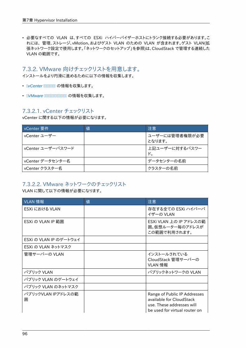
第7章 Hypervisor Installation
96
• 必要なすべての VLAN は、すべての ESXi ハイパーバイザーホストにトランク接続する必要があります。これには、 管理、ストレージ、vMotion、およびゲスト VLAN のための VLAN が含まれます。ゲスト VLAN(拡張ネットワーク設定で使用します。「ネットワークのセットアップ」を参照)は、CloudStack で管理する連続したVLAN の範囲です。
7.3.2. VMware 向けチェックリストを用意します。インストールをより円滑に進めるために以下の情報を収集します。
• �vCenter �������� の情報を収集します。
• �VMware ��������������� の情報を収集します。
7.3.2.1. vCenter チェックリストvCenter に関する以下の情報が必要になります。
vCenter 要件 値 注意
vCenter ユーザー ユーザーには管理者権限が必要となります。
vCenter ユーザーパスワード 上記ユーザーに対するパスワード。
vCenter データセンター名 データセンターの名前
vCenter クラスター名 クラスターの名前
7.3.2.2. VMware ネットワークのチェックリストVLAN に関して以下の情報が必要になります。
VLAN 情報 値 注意
ESXi における VLAN 存在する全ての ESXi ハイパーバイザーの VLAN
ESXi の VLAN IP 範囲 ESXi VLAN 上の IP アドレスの範囲。仮想ルーター毎のアドレスがこの範囲で利用されます。
ESXi の VLAN IP のゲートウェイ
ESXi の VLAN ネットマスク
管理サーバーの VLAN インストールされているCloudStack 管理サーバーのVLAN 情報
パブリック VLAN パブリックネットワークの VLAN
パブリック VLAN のゲートウェイ
パブリック VLAN のネットマスク
パブリックVLAN IPアドレスの範囲
Range of Public IP Addressesavailable for CloudStackuse. These addresses willbe used for virtual router on
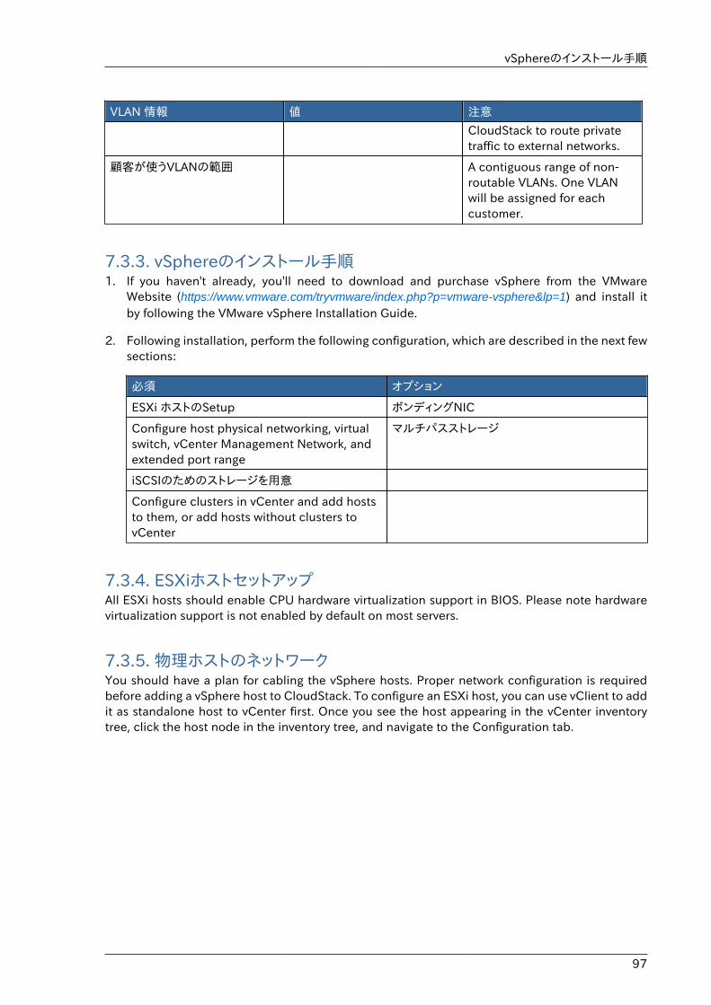
vSphereのインストール手順
97
VLAN 情報 値 注意
CloudStack to route privatetraffic to external networks.
顧客が使うVLANの範囲 A contiguous range of non-routable VLANs. One VLANwill be assigned for eachcustomer.
7.3.3. vSphereのインストール手順1. If you haven't already, you'll need to download and purchase vSphere from the VMware
Website (https://www.vmware.com/tryvmware/index.php?p=vmware-vsphere&lp=1) and install itby following the VMware vSphere Installation Guide.
2. Following installation, perform the following configuration, which are described in the next fewsections:
必須 オプション
ESXi ホストのSetup ボンディングNIC
Configure host physical networking, virtualswitch, vCenter Management Network, andextended port range
マルチパスストレージ
iSCSIのためのストレージを用意
Configure clusters in vCenter and add hoststo them, or add hosts without clusters tovCenter
7.3.4. ESXiホストセットアップAll ESXi hosts should enable CPU hardware virtualization support in BIOS. Please note hardwarevirtualization support is not enabled by default on most servers.
7.3.5. 物理ホストのネットワークYou should have a plan for cabling the vSphere hosts. Proper network configuration is requiredbefore adding a vSphere host to CloudStack. To configure an ESXi host, you can use vClient to addit as standalone host to vCenter first. Once you see the host appearing in the vCenter inventorytree, click the host node in the inventory tree, and navigate to the Configuration tab.
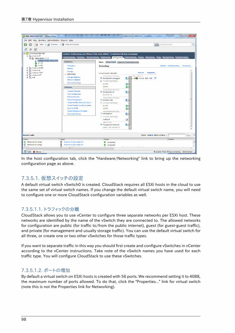
第7章 Hypervisor Installation
98
In the host configuration tab, click the "Hardware/Networking" link to bring up the networkingconfiguration page as above.
7.3.5.1. 仮想スイッチの設定A default virtual switch vSwitch0 is created. CloudStack requires all ESXi hosts in the cloud to usethe same set of virtual switch names. If you change the default virtual switch name, you will needto configure one or more CloudStack configuration variables as well.
7.3.5.1.1. トラフィックの分離CloudStack allows you to use vCenter to configure three separate networks per ESXi host. Thesenetworks are identified by the name of the vSwitch they are connected to. The allowed networksfor configuration are public (for traffic to/from the public internet), guest (for guest-guest traffic),and private (for management and usually storage traffic). You can use the default virtual switch forall three, or create one or two other vSwitches for those traffic types.
If you want to separate traffic in this way you should first create and configure vSwitches in vCenteraccording to the vCenter instructions. Take note of the vSwitch names you have used for eachtraffic type. You will configure CloudStack to use these vSwitches.
7.3.5.1.2. ポートの増加By default a virtual switch on ESXi hosts is created with 56 ports. We recommend setting it to 4088,the maximum number of ports allowed. To do that, click the "Properties..." link for virtual switch(note this is not the Properties link for Networking).
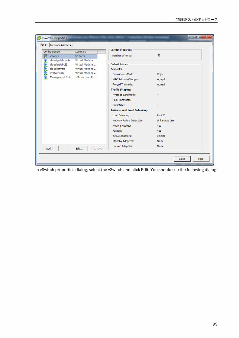
物理ホストのネットワーク
99
In vSwitch properties dialog, select the vSwitch and click Edit. You should see the following dialog:
第7章 Hypervisor Installation
100
In this dialog, you can change the number of switch ports. After you've done that, ESXi hosts arerequired to reboot in order for the setting to take effect.
7.3.5.2. vCenter マネージメントネットワークの設定In the vSwitch properties dialog box, you may see a vCenter management network. This samenetwork will also be used as the CloudStack management network. CloudStack requires thevCenter management network to be configured properly. Select the management network item inthe dialog, then click Edit.
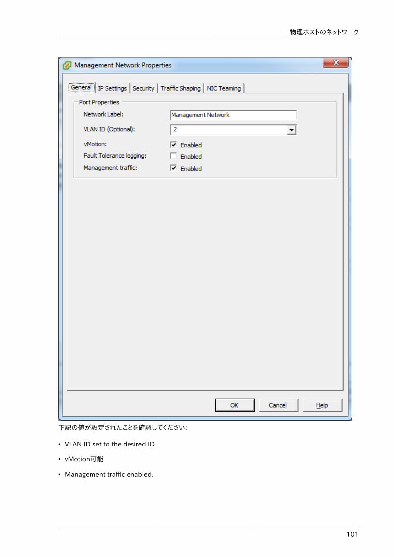
物理ホストのネットワーク
101
下記の値が設定されたことを確認してください:
• VLAN ID set to the desired ID
• vMotion可能
• Management traffic enabled.
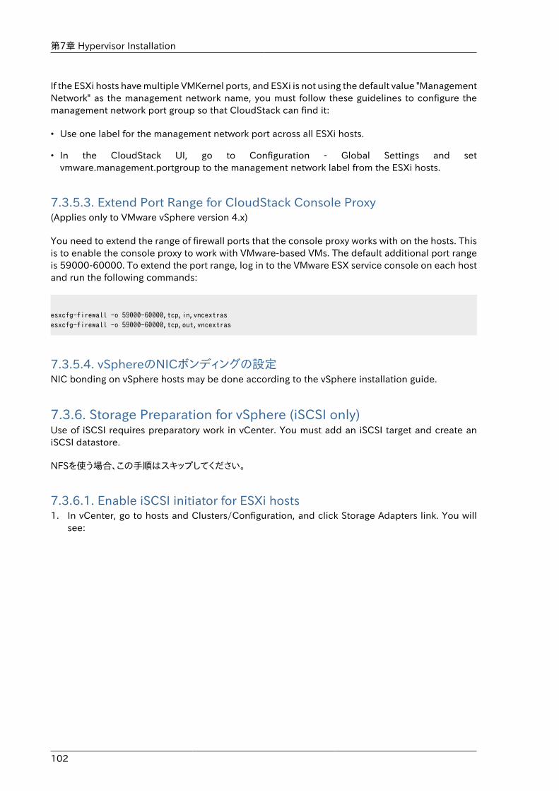
第7章 Hypervisor Installation
102
If the ESXi hosts have multiple VMKernel ports, and ESXi is not using the default value "ManagementNetwork" as the management network name, you must follow these guidelines to configure themanagement network port group so that CloudStack can find it:
• Use one label for the management network port across all ESXi hosts.
• In the CloudStack UI, go to Configuration - Global Settings and setvmware.management.portgroup to the management network label from the ESXi hosts.
7.3.5.3. Extend Port Range for CloudStack Console Proxy(Applies only to VMware vSphere version 4.x)
You need to extend the range of firewall ports that the console proxy works with on the hosts. Thisis to enable the console proxy to work with VMware-based VMs. The default additional port rangeis 59000-60000. To extend the port range, log in to the VMware ESX service console on each hostand run the following commands:
esxcfg-firewall -o 59000-60000,tcp,in,vncextrasesxcfg-firewall -o 59000-60000,tcp,out,vncextras
7.3.5.4. vSphereのNICボンディングの設定NIC bonding on vSphere hosts may be done according to the vSphere installation guide.
7.3.6. Storage Preparation for vSphere (iSCSI only)Use of iSCSI requires preparatory work in vCenter. You must add an iSCSI target and create aniSCSI datastore.
NFSを使う場合、この手順はスキップしてください。
7.3.6.1. Enable iSCSI initiator for ESXi hosts1. In vCenter, go to hosts and Clusters/Configuration, and click Storage Adapters link. You will
see:
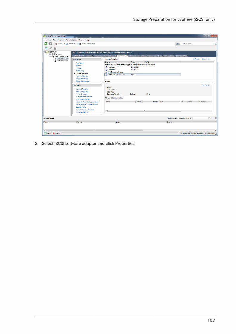
Storage Preparation for vSphere (iSCSI only)
103
2. Select iSCSI software adapter and click Properties.
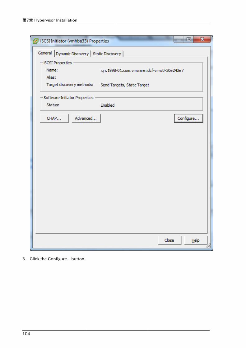
第7章 Hypervisor Installation
104
3. Click the Configure... button.
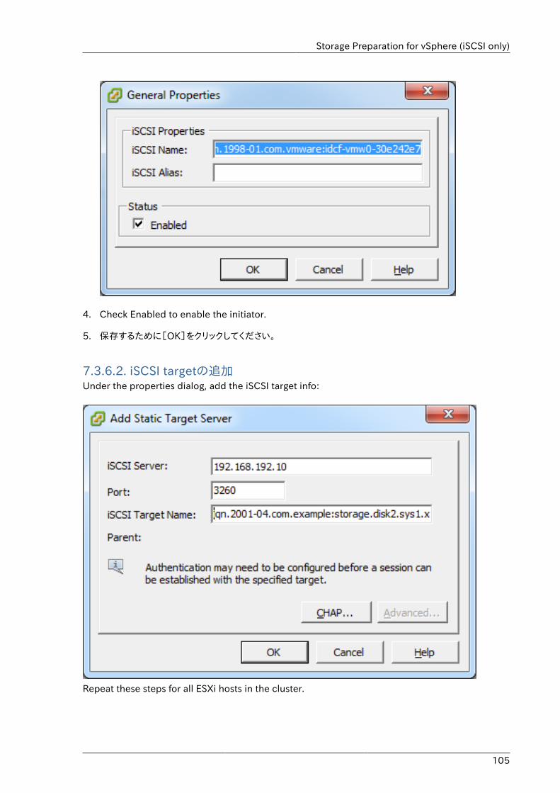
Storage Preparation for vSphere (iSCSI only)
105
4. Check Enabled to enable the initiator.
5. 保存するために[OK]をクリックしてください。
7.3.6.2. iSCSI targetの追加Under the properties dialog, add the iSCSI target info:
Repeat these steps for all ESXi hosts in the cluster.
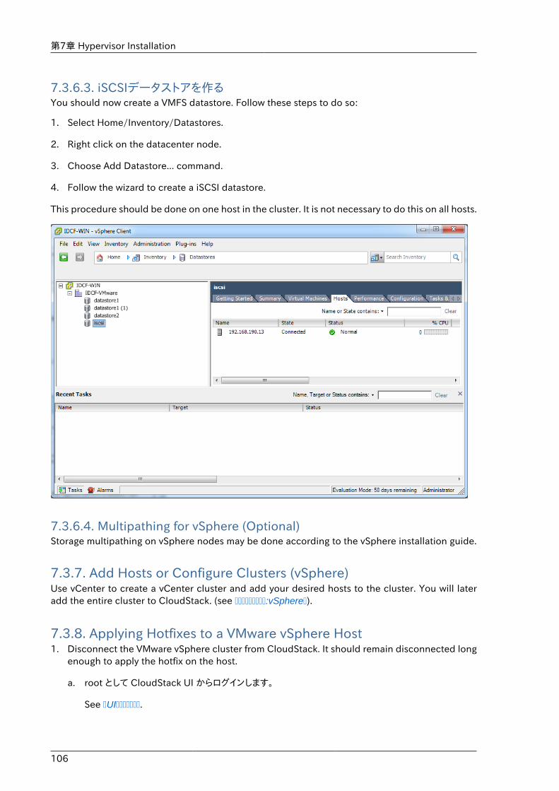
第7章 Hypervisor Installation
106
7.3.6.3. iSCSIデータストアを作るYou should now create a VMFS datastore. Follow these steps to do so:
1. Select Home/Inventory/Datastores.
2. Right click on the datacenter node.
3. Choose Add Datastore... command.
4. Follow the wizard to create a iSCSI datastore.
This procedure should be done on one host in the cluster. It is not necessary to do this on all hosts.
7.3.6.4. Multipathing for vSphere (Optional)Storage multipathing on vSphere nodes may be done according to the vSphere installation guide.
7.3.7. Add Hosts or Configure Clusters (vSphere)Use vCenter to create a vCenter cluster and add your desired hosts to the cluster. You will lateradd the entire cluster to CloudStack. (see ���������:vSphere�).
7.3.8. Applying Hotfixes to a VMware vSphere Host1. Disconnect the VMware vSphere cluster from CloudStack. It should remain disconnected long
enough to apply the hotfix on the host.
a. root として CloudStack UI からログインします。
See �UI�������.
Applying Hotfixes to a VMware vSphere Host
107
b. Navigate to the VMware cluster, click Actions, and select Unmanage.
c. [Unmanaged] が表示されるまで状態を監視します。
2. Perform the following on each of the ESXi hosts in the cluster:
a. Move each of the ESXi hosts in the cluster to maintenance mode.
b. Ensure that all the VMs are migrated to other hosts in that cluster.
c. If there is only one host in that cluster, shutdown all the VMs and move the host intomaintenance mode.
d. Apply the patch on the ESXi host.
e. 表示されたら再起動します。
f. ホストのメンテナンスモードをキャンセルします。
3. クラスタをCloudStack に再接続します。
a. root として CloudStack UI からログインします。
b. Navigate to the VMware cluster, click Actions, and select Manage.
c. Watch the status to see that all the hosts come up. It might take several minutes for thehosts to come up.
Alternatively, verify the host state is properly synchronized and updated in the CloudStackdatabase.

108
109
Additional Installation OptionsThe next few sections describe CloudStack features above and beyond the basic deploymentoptions.
8.1. 使用状況測定サーバーのインストール(オプション)管理サーバーを正しく構成したら、オプションで使用状況測定サーバーをインストールできます。使用状況測定サーバーでシステム内のイベントからデータを取得して、使用状況に基づいてアカウントに課金することができます。
複数の管理サーバーが存在する場合は、使用状況測定サーバーはそのいずれかにインストールできます。使用状況測定サーバーによって使用状況データの処理が調整されます。可用性が懸念されるサイトでは、使用状況測定サーバーを少なくとも 2 台の管理サーバーにインストールする必要があります。
8.1.1. 使用状況測定サーバーのインストール要件• 使用状況測定サーバーをインストールするときには、管理サーバーが動作している必要があります。
• 使用状況測定サーバーは管理サーバーと同じサーバーにインストールする必要があります。
8.1.2. 使用状況測定サーバーのインストール手順1. ./install.sh を実行します。
# ./install.sh
インストーラーの準備が進むにつれていくつかのメッセージが表示され、その後に選択項目の一覧が表示されま す。
2. Choose "S" to install the Usage Server.
> S
3. インストールが完了したら、次のコマンドを実行して使用状況測定サーバーを起動します。
# service cloudstack-usage start
使用状況測定サーバーの詳細な構成について詳しくは、『管理ガイド』を参照してください。
8.2. SSL (Optional)CloudStack provides HTTP access in its default installation. There are a number of technologiesand sites which choose to implement SSL. As a result, we have left CloudStack to expose HTTPunder the assumption that a site will implement its typical practice.
CloudStack uses Tomcat as its servlet container. For sites that would like CloudStack to terminatethe SSL session, Tomcat’s SSL access may be enabled. Tomcat SSL configuration is described athttp://tomcat.apache.org/tomcat-6.0-doc/ssl-howto.html.
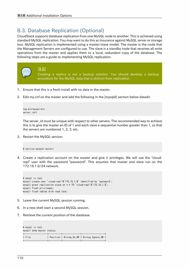
第8章 Additional Installation Options
110
8.3. Database Replication (Optional)CloudStack supports database replication from one MySQL node to another. This is achieved usingstandard MySQL replication. You may want to do this as insurance against MySQL server or storageloss. MySQL replication is implemented using a master/slave model. The master is the node thatthe Management Servers are configured to use. The slave is a standby node that receives all writeoperations from the master and applies them to a local, redundant copy of the database. Thefollowing steps are a guide to implementing MySQL replication.
注記Creating a replica is not a backup solution. You should develop a backupprocedure for the MySQL data that is distinct from replication.
1. Ensure that this is a fresh install with no data in the master.
2. Edit my.cnf on the master and add the following in the [mysqld] section below datadir.
log_bin=mysql-binserver_id=1
The server_id must be unique with respect to other servers. The recommended way to achievethis is to give the master an ID of 1 and each slave a sequential number greater than 1, so thatthe servers are numbered 1, 2, 3, etc.
3. Restart the MySQL service:
# service mysqld restart
4. Create a replication account on the master and give it privileges. We will use the "cloud-repl" user with the password "password". This assumes that master and slave run on the172.16.1.0/24 network.
# mysql -u rootmysql> create user 'cloud-repl'@'172.16.1.%' identified by 'password';mysql> grant replication slave on *.* TO 'cloud-repl'@'172.16.1.%';mysql> flush privileges;mysql> flush tables with read lock;
5. Leave the current MySQL session running.
6. In a new shell start a second MySQL session.
7. Retrieve the current position of the database.
# mysql -u rootmysql> show master status;+------------------+----------+--------------+------------------+| File | Position | Binlog_Do_DB | Binlog_Ignore_DB |+------------------+----------+--------------+------------------+
Database Replication (Optional)
111
| mysql-bin.000001 | 412 | | |+------------------+----------+--------------+------------------+
8. Note the file and the position that are returned by your instance.
9. Exit from this session.
10. Complete the master setup. Returning to your first session on the master, release the locks andexit MySQL.
mysql> unlock tables;
11. Install and configure the slave. On the slave server, run the following commands.
# yum install mysql-server# chkconfig mysqld on
12. Edit my.cnf and add the following lines in the [mysqld] section below datadir.
server_id=2innodb_rollback_on_timeout=1innodb_lock_wait_timeout=600
13. Restart MySQL.
# service mysqld restart
14. Instruct the slave to connect to and replicate from the master. Replace the IP address,password, log file, and position with the values you have used in the previous steps.
mysql> change master to -> master_host='172.16.1.217', -> master_user='cloud-repl', -> master_password='password', -> master_log_file='mysql-bin.000001', -> master_log_pos=412;
15. Then start replication on the slave.
mysql> start slave;
16. Optionally, open port 3306 on the slave as was done on the master earlier.
This is not required for replication to work. But if you choose not to do this, you will need todo it when failover to the replica occurs.
第8章 Additional Installation Options
112
8.3.1. FailoverThis will provide for a replicated database that can be used to implement manual failover for theManagement Servers. CloudStack failover from one MySQL instance to another is performed bythe administrator. In the event of a database failure you should:
1. Stop the Management Servers (via service cloudstack-management stop).
2. Change the replica's configuration to be a master and restart it.
3. Ensure that the replica's port 3306 is open to the Management Servers.
4. Make a change so that the Management Server uses the new database. The simplest processhere is to put the IP address of the new database server into each Management Server's /etc/cloud/management/db.properties.
5. Restart the Management Servers:
# service cloudstack-management start
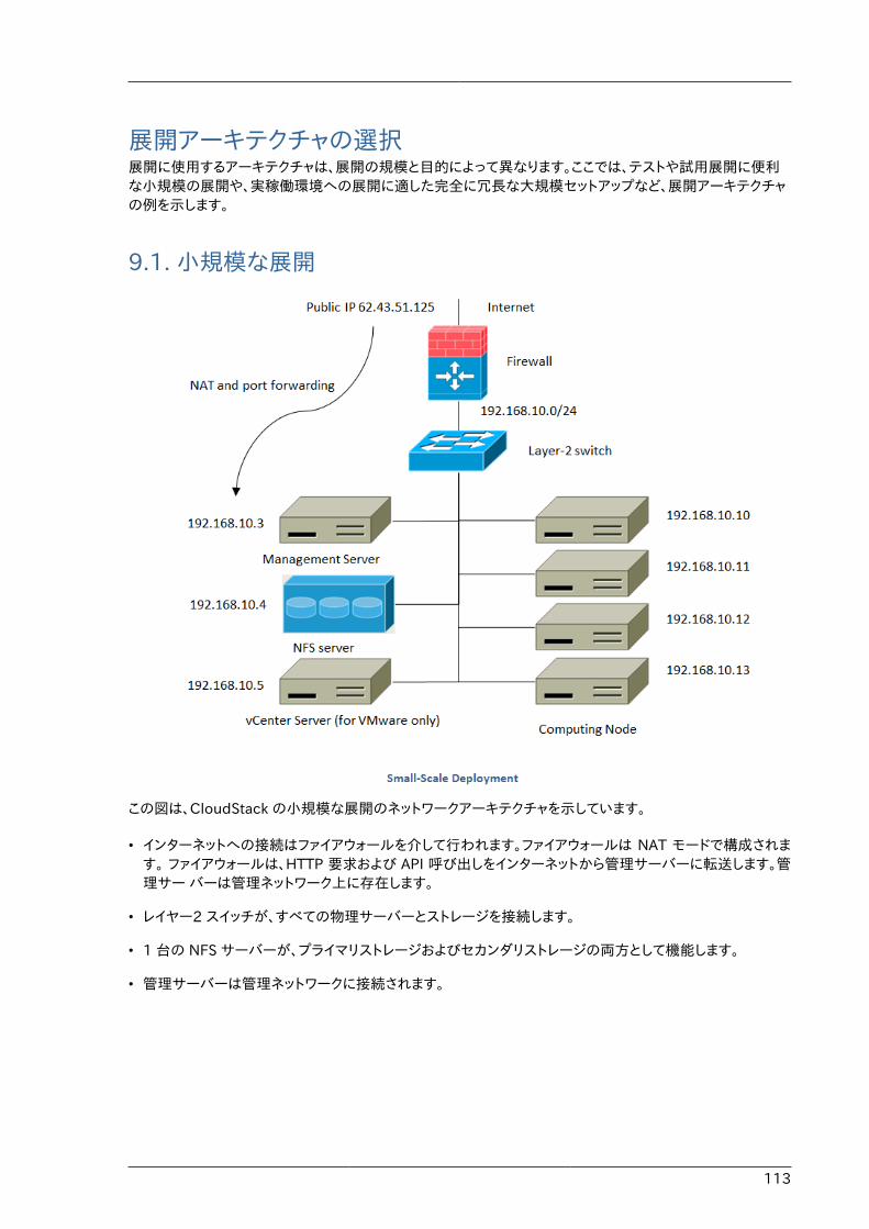
113
展開アーキテクチャの選択展開に使用するアーキテクチャは、展開の規模と目的によって異なります。ここでは、テストや試用展開に便利な小規模の展開や、実稼働環境への展開に適した完全に冗長な大規模セットアップなど、展開アーキテクチャの例を示します。
9.1. 小規模な展開
この図は、CloudStack の小規模な展開のネットワークアーキテクチャを示しています。
• インターネットへの接続はファイアウォールを介して行われます。ファイアウォールは NAT モードで構成されます。 ファイアウォールは、HTTP 要求および API 呼び出しをインターネットから管理サーバーに転送します。管理サー バーは管理ネットワーク上に存在します。
• レイヤー2 スイッチが、すべての物理サーバーとストレージを接続します。
• 1 台の NFS サーバーが、プライマリストレージおよびセカンダリストレージの両方として機能します。
• 管理サーバーは管理ネットワークに接続されます。
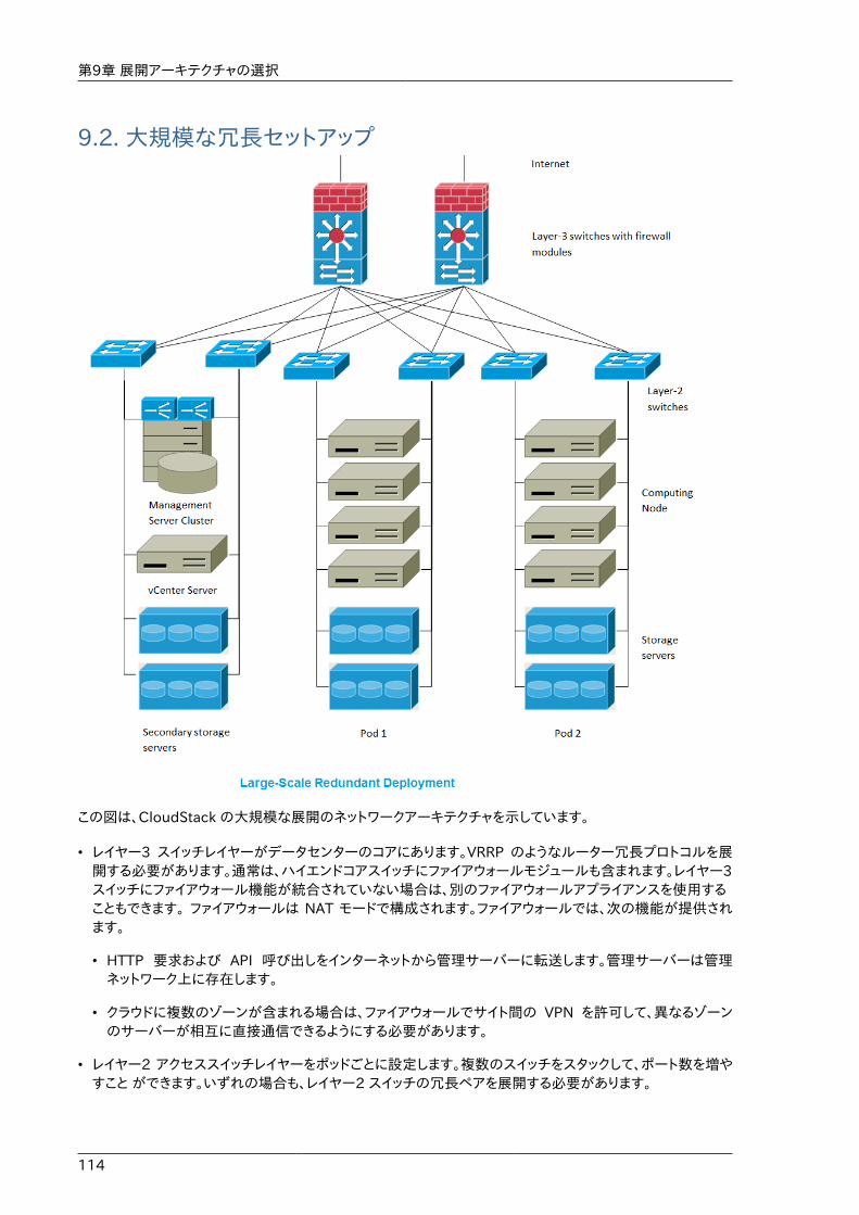
第9章 展開アーキテクチャの選択
114
9.2. 大規模な冗長セットアップ
この図は、CloudStack の大規模な展開のネットワークアーキテクチャを示しています。
• レイヤー3 スイッチレイヤーがデータセンターのコアにあります。VRRP のようなルーター冗長プロトコルを展開する必要があります。通常は、ハイエンドコアスイッチにファイアウォールモジュールも含まれます。レイヤー3スイッチにファイアウォール機能が統合されていない場合は、別のファイアウォールアプライアンスを使用することもできます。 ファイアウォールは NAT モードで構成されます。ファイアウォールでは、次の機能が提供されます。
• HTTP 要求および API 呼び出しをインターネットから管理サーバーに転送します。管理サーバーは管理ネットワーク上に存在します。
• クラウドに複数のゾーンが含まれる場合は、ファイアウォールでサイト間の VPN を許可して、異なるゾーンのサーバーが相互に直接通信できるようにする必要があります。
• レイヤー2 アクセススイッチレイヤーをポッドごとに設定します。複数のスイッチをスタックして、ポート数を増やすこと ができます。いずれの場合も、レイヤー2 スイッチの冗長ペアを展開する必要があります。
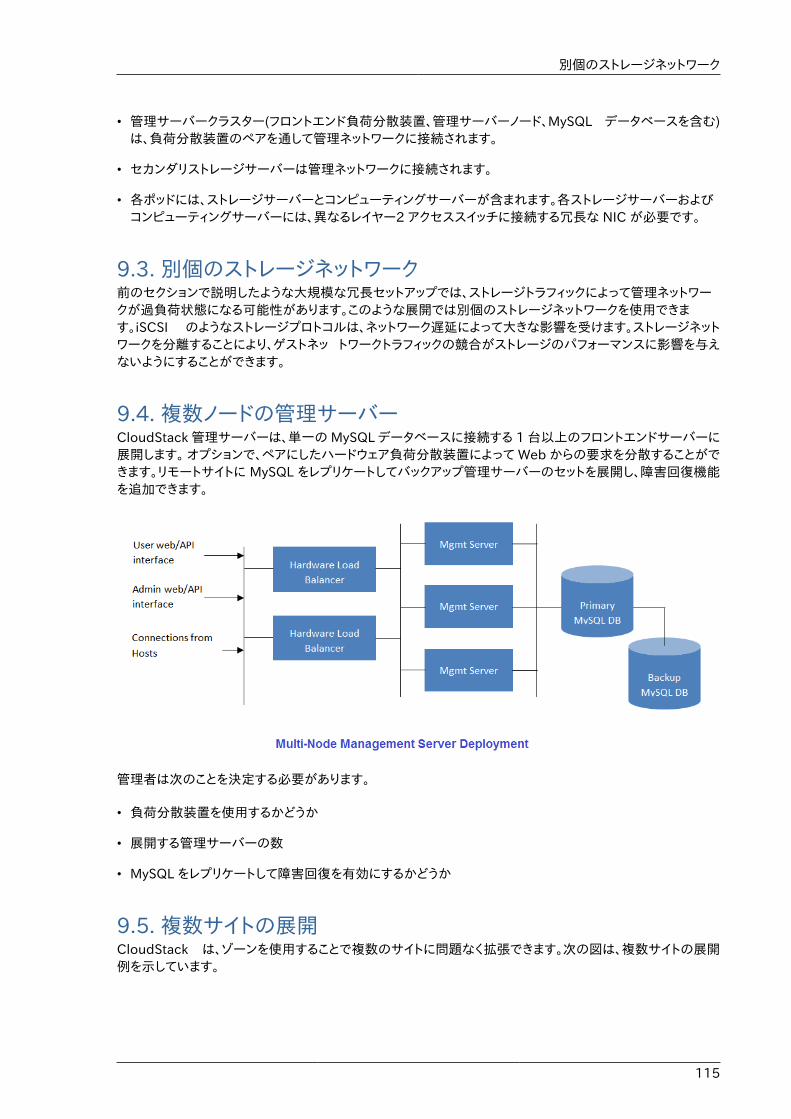
別個のストレージネットワーク
115
• 管理サーバークラスター(フロントエンド負荷分散装置、管理サーバーノード、MySQL データベースを含む)は、負荷分散装置のペアを通して管理ネットワークに接続されます。
• セカンダリストレージサーバーは管理ネットワークに接続されます。
• 各ポッドには、ストレージサーバーとコンピューティングサーバーが含まれます。各ストレージサーバーおよびコンピューティングサーバーには、異なるレイヤー2 アクセススイッチに接続する冗長な NIC が必要です。
9.3. 別個のストレージネットワーク前のセクションで説明したような大規模な冗長セットアップでは、ストレージトラフィックによって管理ネットワークが過負荷状態になる可能性があります。このような展開では別個のストレージネットワークを使用できます。iSCSI のようなストレージプロトコルは、ネットワーク遅延によって大きな影響を受けます。ストレージネットワークを分離することにより、ゲストネッ トワークトラフィックの競合がストレージのパフォーマンスに影響を与えないようにすることができます。
9.4. 複数ノードの管理サーバーCloudStack 管理サーバーは、単一の MySQL データベースに接続する 1 台以上のフロントエンドサーバーに展開します。 オプションで、ペアにしたハードウェア負荷分散装置によって Web からの要求を分散することができます。リモートサイトに MySQL をレプリケートしてバックアップ管理サーバーのセットを展開し、障害回復機能を追加できます。
管理者は次のことを決定する必要があります。
• 負荷分散装置を使用するかどうか
• 展開する管理サーバーの数
• MySQL をレプリケートして障害回復を有効にするかどうか
9.5. 複数サイトの展開CloudStack は、ゾーンを使用することで複数のサイトに問題なく拡張できます。次の図は、複数サイトの展開例を示しています。
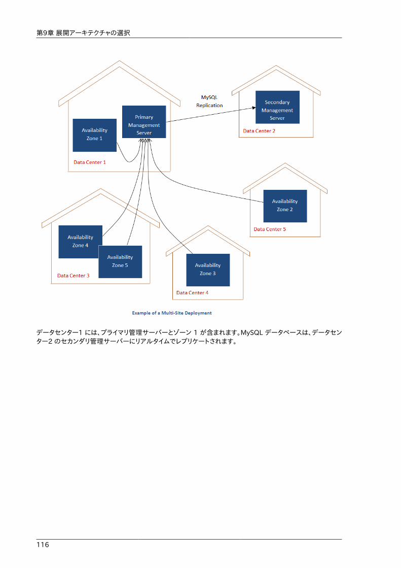
第9章 展開アーキテクチャの選択
116
データセンター1 には、プライマリ管理サーバーとゾーン 1 が含まれます。MySQL データベースは、データセンター2 のセカンダリ管理サーバーにリアルタイムでレプリケートされます。
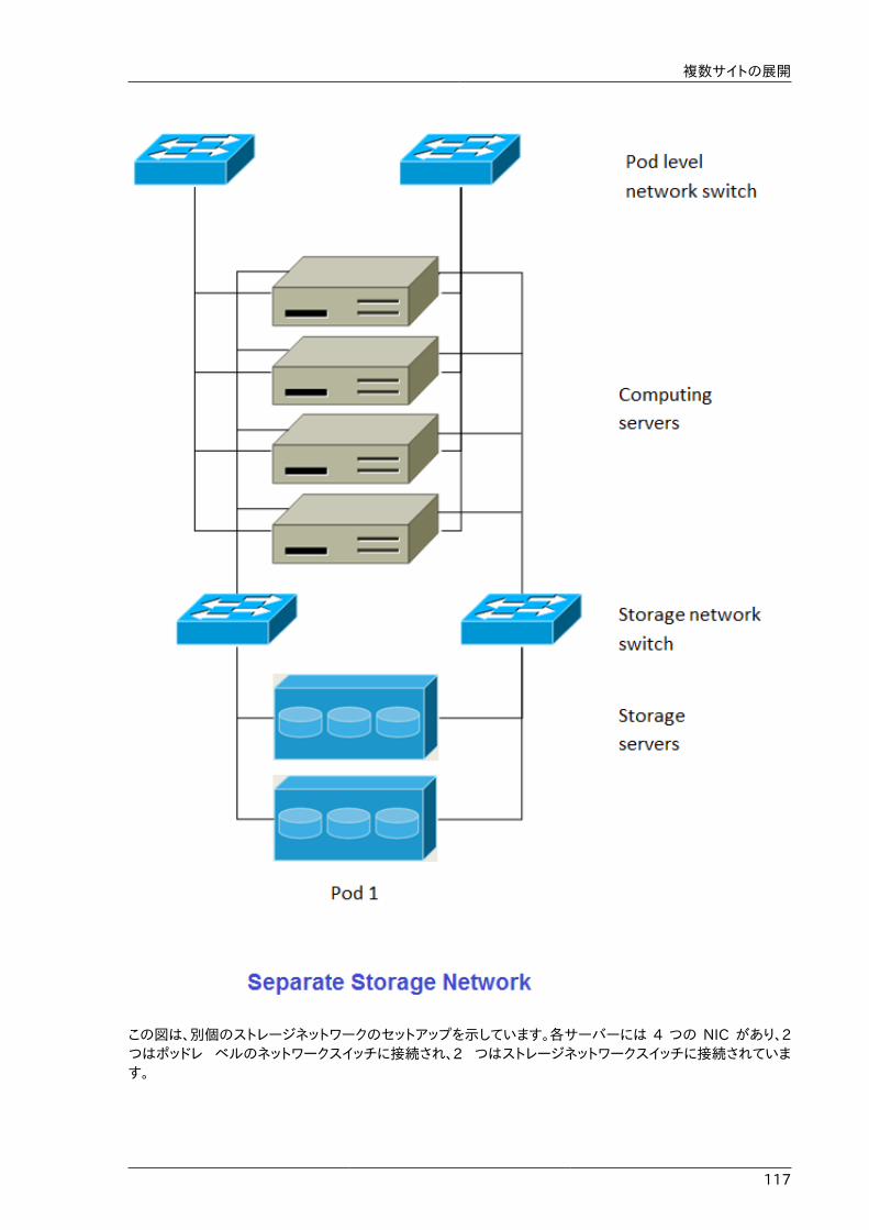
複数サイトの展開
117
この図は、別個のストレージネットワークのセットアップを示しています。各サーバーには 4 つの NIC があり、2つはポッドレ ベルのネットワークスイッチに接続され、2 つはストレージネットワークスイッチに接続されています。
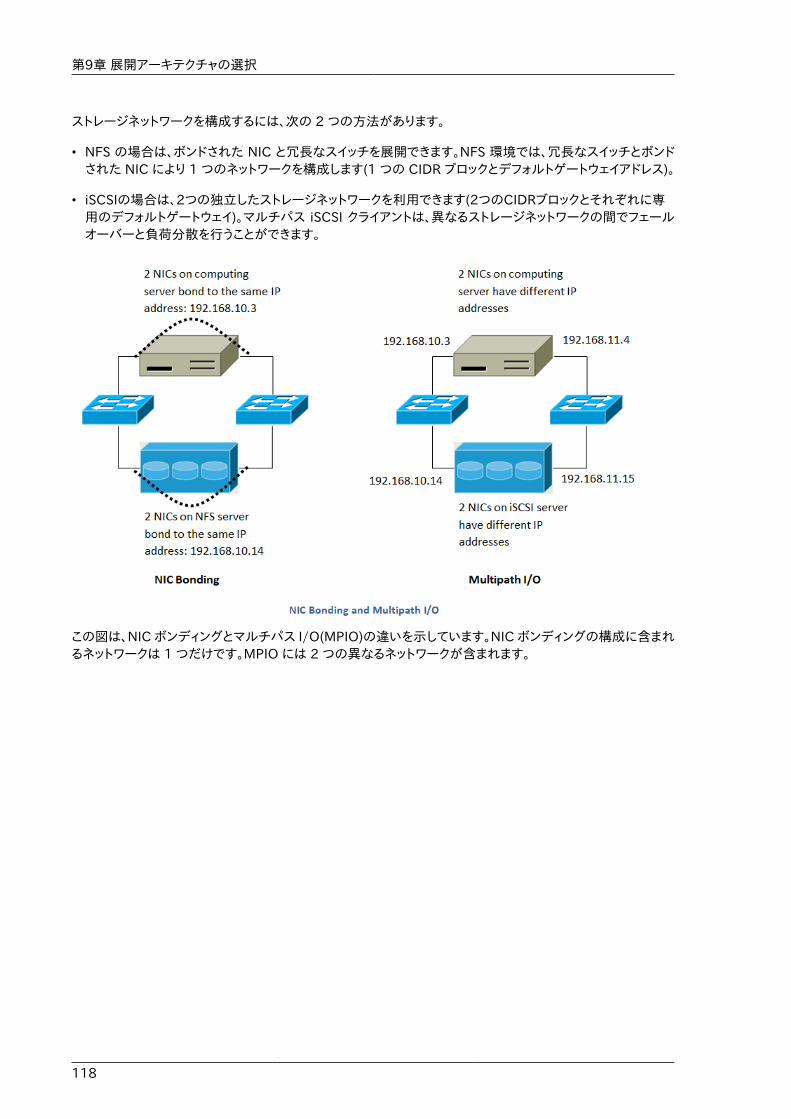
第9章 展開アーキテクチャの選択
118
ストレージネットワークを構成するには、次の 2 つの方法があります。
• NFS の場合は、ボンドされた NIC と冗長なスイッチを展開できます。NFS 環境では、冗長なスイッチとボンドされた NIC により 1 つのネットワークを構成します(1 つの CIDR ブロックとデフォルトゲートウェイアドレス)。
• iSCSIの場合は、2つの独立したストレージネットワークを利用できます(2つのCIDRブロックとそれぞれに専用のデフォルトゲートウェイ)。マルチパス iSCSI クライアントは、異なるストレージネットワークの間でフェールオーバーと負荷分散を行うことができます。
この図は、NIC ボンディングとマルチパス I/O(MPIO)の違いを示しています。NIC ボンディングの構成に含まれるネットワークは 1 つだけです。MPIO には 2 つの異なるネットワークが含まれます。
119
アカウント
10.1. アカウント、ユーザー、およびドメイン
アカウントアカウントは、通常、サービスプロバイダーの顧客や、大規模な組織の部門を表します。1 つのアカウントに複数のユー ザーを存在させることができます。
ドメインアカウントはドメインによってグループ化されます。ドメインには、通常、相互に何らかの論理的な関係がある複数のアカウ ントと、ドメインおよびそのサブドメインに対して何らかの権限を持つ一連の委任管理者が含まれます。たとえば、複数の 販売代理店を持つサービスプロバイダーでは、販売代理店ごとにドメインを作成することができます。
各アカウントはクラウドのインストール時に3つの違う種類のユーザーアカウントとして作成されます: ルート管理者、ドメイン管理者、ユーザー
ユーザーユーザーは、アカウント内のエイリアスのようなものです。同じアカウントのユーザーは互いに分離されませんが、ほかのアカウントのユーザーからは分離されます。ほとんどのインストールでは、1 つのアカウントで複数のユーザーを使用することはないため、ユーザーの概念が問題になることはありません。
ユーザー名はドメインをまたぐアカウント内で一意です。同じユーザー名はサブドメインを含め他のドメイン上で存在することができます。ドメイン名はルートからのフルパス名が一意であれば繰り返す利用することができます。たとえば、root/foo/d1, root/sales/d1 と同様に root/d1 も利用することができます。
管理者はシステム上で特別な権限を持つアカウントです。システムには複数の管理者が存在することができます。管理者は他の管理者を作成、削除することができ、システム上のユーザーのパスワードを変更することができます。
ドメイン管理者ドメイン管理者はドメインに所属するユーザーに対しての管理権限を持つことができます。ドメイン管理者は物理サーバーや他のドメインからは不可視です。
ルート管理者ルート管理者はシステムに対してテンプレート操作、サービスオファリング、ユーザー管理、ドメインなど完全なアクセス権限を持ちます。
アカウントが所有するリソースはアカウント内のユーザー独自のものではありません。たとえば、課金、リソース制限などはアカウント単位で管理されユーザー単位ではありません。ユーザーはアカウントに割り当てられたあらゆるリソースを利用できその権限を持ちます。権限はその役割によって決定付けられます。
10.2. LDAP サーバーによるユーザー認証Microsoft Active Directory や ApacheDS などの外部 LDAP サーバーを使用して CloudStackのエンドユーザーを認証でき ます。クエリフィルターを使用して、CloudStack アカウントを対応する LDAP
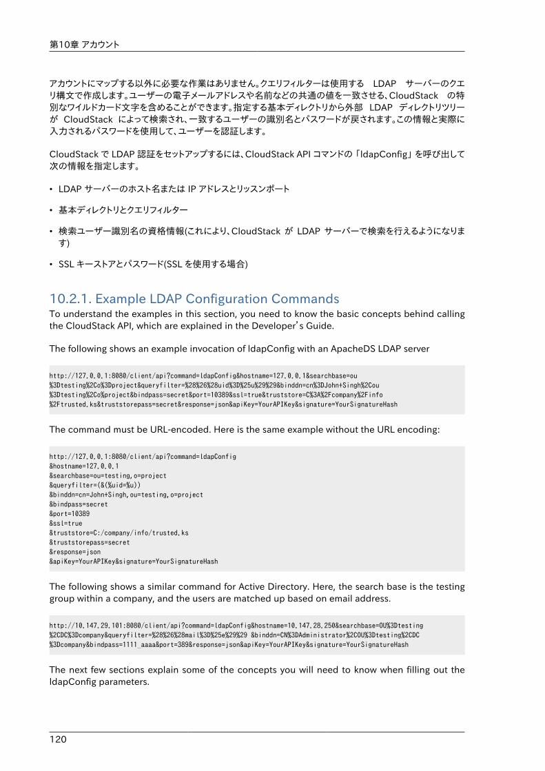
第10章 アカウント
120
アカウントにマップする以外に必要な作業はありません。クエリフィルターは使用する LDAP サーバーのクエリ構文で作成します。ユーザーの電子メールアドレスや名前などの共通の値を一致させる、CloudStack の特別なワイルドカード文字を含めることができます。指定する基本ディレクトリから外部 LDAP ディレクトリツリーが CloudStack によって検索され、一致するユーザーの識別名とパスワードが戻されます。この情報と実際に入力されるパスワードを使用して、ユーザーを認証します。
CloudStack で LDAP 認証をセットアップするには、CloudStack API コマンドの 「ldapConfig」 を呼び出して次の情報を指定します。
• LDAP サーバーのホスト名または IP アドレスとリッスンポート
• 基本ディレクトリとクエリフィルター
• 検索ユーザー識別名の資格情報(これにより、CloudStack が LDAP サーバーで検索を行えるようになります)
• SSL キーストアとパスワード(SSL を使用する場合)
10.2.1. Example LDAP Configuration CommandsTo understand the examples in this section, you need to know the basic concepts behind callingthe CloudStack API, which are explained in the Developer’s Guide.
The following shows an example invocation of ldapConfig with an ApacheDS LDAP server
http://127.0.0.1:8080/client/api?command=ldapConfig&hostname=127.0.0.1&searchbase=ou%3Dtesting%2Co%3Dproject&queryfilter=%28%26%28uid%3D%25u%29%29&binddn=cn%3DJohn+Singh%2Cou%3Dtesting%2Co%project&bindpass=secret&port=10389&ssl=true&truststore=C%3A%2Fcompany%2Finfo%2Ftrusted.ks&truststorepass=secret&response=json&apiKey=YourAPIKey&signature=YourSignatureHash
The command must be URL-encoded. Here is the same example without the URL encoding:
http://127.0.0.1:8080/client/api?command=ldapConfig&hostname=127.0.0.1&searchbase=ou=testing,o=project&queryfilter=(&(%uid=%u))&binddn=cn=John+Singh,ou=testing,o=project&bindpass=secret&port=10389&ssl=true&truststore=C:/company/info/trusted.ks&truststorepass=secret&response=json&apiKey=YourAPIKey&signature=YourSignatureHash
The following shows a similar command for Active Directory. Here, the search base is the testinggroup within a company, and the users are matched up based on email address.
http://10.147.29.101:8080/client/api?command=ldapConfig&hostname=10.147.28.250&searchbase=OU%3Dtesting%2CDC%3Dcompany&queryfilter=%28%26%28mail%3D%25e%29%29 &binddn=CN%3DAdministrator%2COU%3Dtesting%2CDC%3Dcompany&bindpass=1111_aaaa&port=389&response=json&apiKey=YourAPIKey&signature=YourSignatureHash
The next few sections explain some of the concepts you will need to know when filling out theldapConfig parameters.
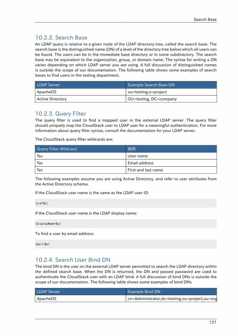
Search Base
121
10.2.2. Search BaseAn LDAP query is relative to a given node of the LDAP directory tree, called the search base. Thesearch base is the distinguished name (DN) of a level of the directory tree below which all users canbe found. The users can be in the immediate base directory or in some subdirectory. The searchbase may be equivalent to the organization, group, or domain name. The syntax for writing a DNvaries depending on which LDAP server you are using. A full discussion of distinguished namesis outside the scope of our documentation. The following table shows some examples of searchbases to find users in the testing department..
LDAP Server Example Search Base DN
ApacheDS ou=testing,o=project
Active Directory OU=testing, DC=company
10.2.3. Query FilterThe query filter is used to find a mapped user in the external LDAP server. The query filtershould uniquely map the CloudStack user to LDAP user for a meaningful authentication. For moreinformation about query filter syntax, consult the documentation for your LDAP server.
The CloudStack query filter wildcards are:
Query Filter Wildcard 説明
%u User name
%e Email address
%n First and last name
The following examples assume you are using Active Directory, and refer to user attributes fromthe Active Directory schema.
If the CloudStack user name is the same as the LDAP user ID:
(uid=%u)
If the CloudStack user name is the LDAP display name:
(displayName=%u)
To find a user by email address:
(mail=%e)
10.2.4. Search User Bind DNThe bind DN is the user on the external LDAP server permitted to search the LDAP directory withinthe defined search base. When the DN is returned, the DN and passed password are used toauthenticate the CloudStack user with an LDAP bind. A full discussion of bind DNs is outside thescope of our documentation. The following table shows some examples of bind DNs.
LDAP Server Example Bind DN
ApacheDS cn=Administrator,dc=testing,ou=project,ou=org

第10章 アカウント
122
LDAP Server Example Bind DN
Active Directory CN=Administrator, OU=testing, DC=company,DC=com
10.2.5. SSL キーストアのパスとパスワードLDAPサーバーがSSLを要求する場合、ldapConfigコマンドでssl、truststore、truststorepassを設定することで有効にする必要があります。SSLをldapConfigで有効にする前に、LDAPサーバーが使用している証明書を取得し、信頼されたキーストアに追加します。キーストアのパスとパスワードを把握しておく必要があります。
123
User Services OverviewIn addition to the physical and logical infrastructure of your cloud, and the CloudStack softwareand servers, you also need a layer of user services so that people can actually make use of thecloud. This means not just a user UI, but a set of options and resources that users can choosefrom, such as templates for creating virtual machines, disk storage, and more. If you are running acommercial service, you will be keeping track of what services and resources users are consumingand charging them for that usage. Even if you do not charge anything for people to use your cloud –say, if the users are strictly internal to your organization, or just friends who are sharing your cloud– you can still keep track of what services they use and how much of them.
11.1. Service Offerings, Disk Offerings, Network Offerings,and TemplatesA user creating a new instance can make a variety of choices about its characteristics andcapabilities. CloudStack provides several ways to present users with choices when creating a newinstance:
• Service Offerings, defined by the CloudStack administrator, provide a choice of CPU speed,number of CPUs, RAM size, tags on the root disk, and other choices. See Creating a New ComputeOffering.
• Disk Offerings, defined by the CloudStack administrator, provide a choice of disk size for primarydata storage. See Creating a New Disk Offering.
• Network Offerings, defined by the CloudStack administrator, describe the feature set that isavailable to end users from the virtual router or external networking devices on a given guestnetwork. See Network Offerings.
• Templates, defined by the CloudStack administrator or by any CloudStack user, are the base OSimages that the user can choose from when creating a new instance. For example, CloudStackincludes CentOS as a template. See Working with Templates.
In addition to these choices that are provided for users, there is another type of service offeringwhich is available only to the CloudStack root administrator, and is used for configuring virtualinfrastructure resources. For more information, see Upgrading a Virtual Router with System ServiceOfferings.

124
125
プロジェクトによるユーザーとリソースの組織化
12.1. プロジェクトの概要CloudStackユーザーはプロジェクトチームを組織して協力し合い、仮想マシン、スナップショット、テンプレート、データディスク、およびIPアドレスなどの仮想リソースを共有することができます。CloudStackによってプロジェクトおよびユーザーごとのリソース使用状況が追跡されるため、ユーザーアカウントまたはプロジェクト単位で使用料を請求することができます。たとえば、ソフトウェア会社の品質保証部門のすべてのメンバーを、プライベートクラウド内の1つのプロジェクトに割り当てます。プロジェクトメンバーは同じクラウドのほかのユーザーの作業から自分たちの作業を簡単に分離できる一方で、会社はテストに使用されるリソースを追跡することができます。
どのユーザーも新しいプロジェクトを作成できるように構成したり、この機能をCloudStack管理者のみに制限したりすることができます。プロジェクトを作成すると、自身がそのプロジェクトの管理者になり、自分のドメイン内のほかのユーザーをプロジェクトに追加できます。ユーザーをプロジェクトに直接追加できるようにするか、招待状の送信を必須とするようにCloudStackをセットアップできます。招待状を必須とする場合は、受信者はこの招待状を承諾する必要があります。プロジェクトメンバーは、プロジェクト内のどのユーザーが作成した仮想リソースも表示および管理できます(たとえば、共有仮想マシンなど)。ユーザーがメンバーになれるプロジェクトの数に制限はありません。CloudStackユーザーインターフェイスのビューを切り替えれば、プロジェクト仮想マシン、仲間のプロジェクトメンバー、プロジェクト関連のアラートなど、プロジェクトに関する情報のみを表示することができます。
プロジェクト管理者は、その役割を別のプロジェクトメンバーに委任できます。また、プロジェクト管理者は、さらにメンバーを追加したり、メンバーをプロジェクトから削除したり、(CloudStack管理者が設定するグローバルデフォルト以下であることが条件ですが)新しいリソース制限を設定したり、プロジェクトを削除したりすることもできます。管理者がメンバーをプロジェクトから削除すると、そのユーザーが作成した仮想マシンインスタンスなどのリソースはプロジェクトと共に残ります。これにより、リソースの所有権と、どのリソースをプロジェクトで使用できるかという問題が生じます。
プロジェクト内で作成されたリソースは、特定のCloudStackアカウントではなく、プロジェクトによって所有され、プロジェクト内のみで使用できます。プロジェクトに属するユーザーは、プロジェクトの外にもリソースを作成できます。そのようなリソースはユーザーのアカウントに属し、プロジェクトの使用状況やリソース制限の対象にはなりません。プロジェクトレベルのネットワークを作成して、プロジェクト内のトラフィックを分離し、ポート転送、負荷分散、VPN、静的NATなどのネットワークサービスを提供できます。プロジェクトでは、特定の種類のリソースが共有されている場合には、プロジェクトの外からそのリソースを利用することもできます。たとえば、共有ネットワークまたはパブリックテンプレートは、ドメイン内のどのプロジェクトでも使用できます。テンプレートの所有者が許可すれば、プロジェクトでプライベートテンプレートにアクセスできます。プロジェクトでは、そのドメインで使用できるどのサービスオファリングまたはディスクオファリングも使用できますが、プロジェクトレベルではプライベートサービスオファリングもディスクオファリングも作成できません。
12.2. プロジェクトの構成CloudStack ユーザーがプロジェクトを使用する前に、CloudStack 管理者はプロジェクトをサポートするためにさまざまなシステムをセットアップする必要があります。これには、プロジェクトメンバーになるための招待状、プロジェクトのリソース制限、プロジェクトを作成できるユーザーの制御が含まれます。
12.2.1. 招待状のセットアッププロジェクト管理者がユーザーをプロジェクトに直接追加できるようにするか、招待状の送信を必須とするように CloudStack をセットアップできます。招待状を必須とする場合は、受信者はこの招待状を承諾する必要があります。招待状は電子メールまたはユーザーの CloudStack アカウントから送信できます。管理者が招待状を
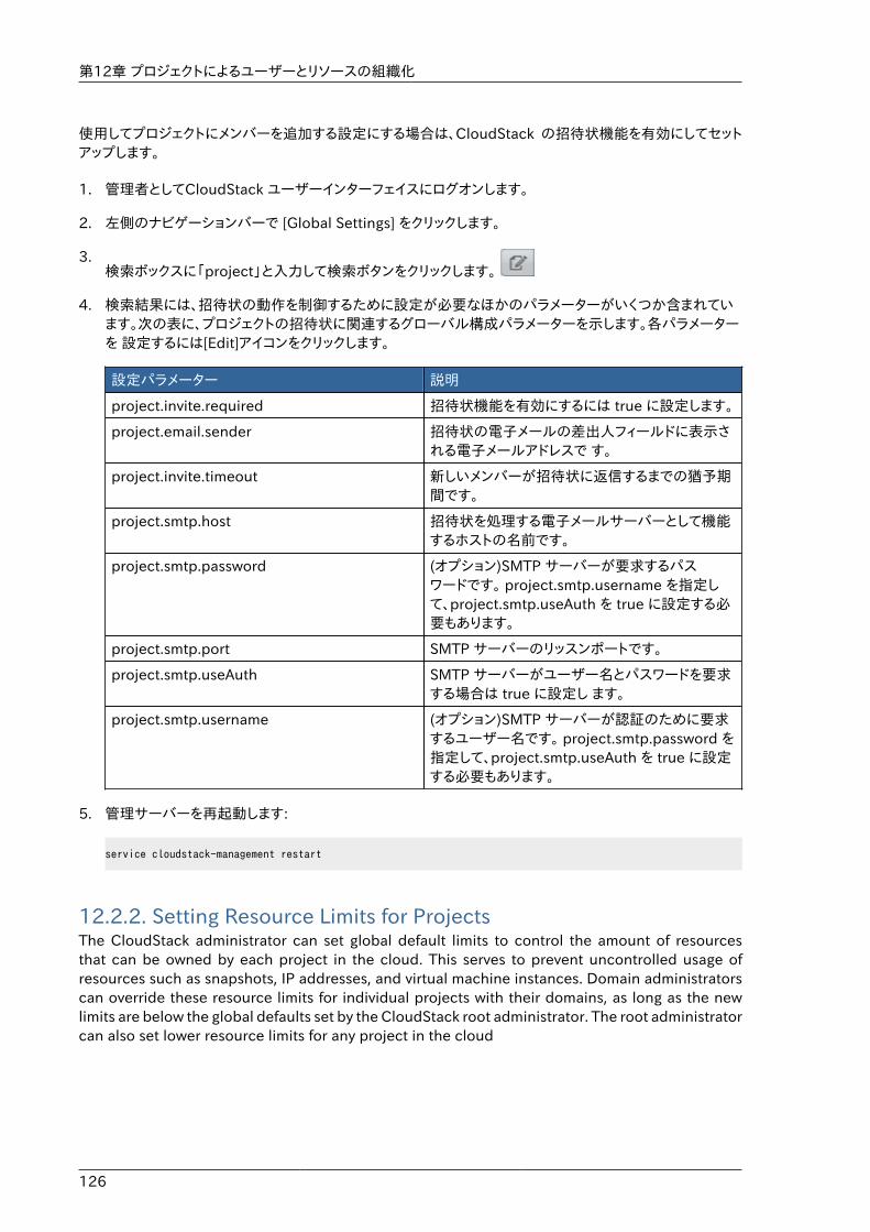
第12章 プロジェクトによるユーザーとリソースの組織化
126
使用してプロジェクトにメンバーを追加する設定にする場合は、CloudStack の招待状機能を有効にしてセットアップします。
1. 管理者としてCloudStack ユーザーインターフェイスにログオンします。
2. 左側のナビゲーションバーで [Global Settings] をクリックします。
3.検索ボックスに「project」と入力して検索ボタンをクリックします。
4. 検索結果には、招待状の動作を制御するために設定が必要なほかのパラメーターがいくつか含まれています。次の表に、プロジェクトの招待状に関連するグローバル構成パラメーターを示します。各パラメーターを 設定するには[Edit]アイコンをクリックします。
設定パラメーター 説明
project.invite.required 招待状機能を有効にするには true に設定します。
project.email.sender 招待状の電子メールの差出人フィールドに表示される電子メールアドレスで す。
project.invite.timeout 新しいメンバーが招待状に返信するまでの猶予期間です。
project.smtp.host 招待状を処理する電子メールサーバーとして機能するホストの名前です。
project.smtp.password (オプション)SMTP サーバーが要求するパスワードです。 project.smtp.username を指定して、project.smtp.useAuth を true に設定する必要もあります。
project.smtp.port SMTP サーバーのリッスンポートです。
project.smtp.useAuth SMTP サーバーがユーザー名とパスワードを要求する場合は true に設定し ます。
project.smtp.username (オプション)SMTP サーバーが認証のために要求するユーザー名です。 project.smtp.password を指定して、project.smtp.useAuth を true に設定する必要もあります。
5. 管理サーバーを再起動します:
service cloudstack-management restart
12.2.2. Setting Resource Limits for ProjectsThe CloudStack administrator can set global default limits to control the amount of resourcesthat can be owned by each project in the cloud. This serves to prevent uncontrolled usage ofresources such as snapshots, IP addresses, and virtual machine instances. Domain administratorscan override these resource limits for individual projects with their domains, as long as the newlimits are below the global defaults set by the CloudStack root administrator. The root administratorcan also set lower resource limits for any project in the cloud
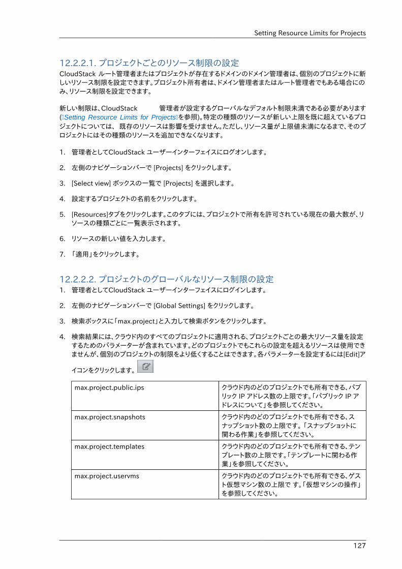
Setting Resource Limits for Projects
127
12.2.2.1. プロジェクトごとのリソース制限の設定CloudStack ルート管理者またはプロジェクトが存在するドメインのドメイン管理者は、個別のプロジェクトに新しいリソース制限を設定できます。プロジェクト所有者は、ドメイン管理者またはルート管理者でもある場合にのみ、リソース制限を設定できます。
新しい制限は、CloudStack 管理者が設定するグローバルなデフォルト制限未満である必要があります(�Setting Resource Limits for Projects�を参照)。特定の種類のリソースが新しい上限を既に超えているプロジェクトについては、 既存のリソースは影響を受けません。ただし、リソース量が上限値未満になるまで、そのプロジェクトにはその種類のリソースを追加できなくなります。
1. 管理者としてCloudStack ユーザーインターフェイスにログオンします。
2. 左側のナビゲーションバーで [Projects] をクリックします。
3. [Select view] ボックスの一覧で [Projects] を選択します。
4. 設定するプロジェクトの名前をクリックします。
5. [Resources]タブをクリックします。このタブには、プロジェクトで所有を許可されている現在の最大数が、リソースの種類ごとに一覧表示されます。
6. リソースの新しい値を入力します。
7. 「適用」をクリックします。
12.2.2.2. プロジェクトのグローバルなリソース制限の設定1. 管理者としてCloudStack ユーザーインターフェイスにログインします。
2. 左側のナビゲーションバーで [Global Settings] をクリックします。
3. 検索ボックスに「max.project」と入力して検索ボタンをクリックします。
4. 検索結果には、クラウド内のすべてのプロジェクトに適用される、プロジェクトごとの最大リソース量を設定するためのパラメーターが含まれています。どのプロジェクトでもこれらの設定を超えるリソースは使用できませんが、個別のプロジェクトの制限をより低くすることはできます。各パラメーターを設定するには[Edit]ア
イコンをクリックします。
max.project.public.ips クラウド内のどのプロジェクトでも所有できる、パブリック IP アドレス数の上限です。「パブリック IP アドレスについて」を参照してください。
max.project.snapshots クラウド内のどのプロジェクトでも所有できる、スナップショット数の上限です。 「スナップショットに関わる作業」を参照してください。
max.project.templates クラウド内のどのプロジェクトでも所有できる、テンプレート数の上限です。「テンプレートに関わる作業」を参照してください。
max.project.uservms クラウド内のどのプロジェクトでも所有できる、ゲスト仮想マシン数の上限で す。「仮想マシンの操作」を参照してください。
第12章 プロジェクトによるユーザーとリソースの組織化
128
max.project.volumes クラウド内のどのプロジェクトでも所有できる、データボリューム数の上限です。「ボリュームについて」を参照してください。
5. 管理サーバーを再起動します。
# service cloudstack-management restart
12.2.3. プロジェクト作成者の権限の設定どのユーザーも新しいプロジェクトを作成できる構成にすることも、この機能を CloudStack 管理者のみに制限することもで きます。
1. 管理者としてCloudStack ユーザーインターフェイスにログオンします。
2. 左側のナビゲーションバーで [Global Settings] をクリックします。
3. 検索ボックスに「allow.user.create.projects」と入力します。
4.パラメーターを設定するには[Edit]アイコンをクリックします。
allow.user.create.projects エンドユーザーがプロジェクトを作成できるようにするには true に設定します。 CloudStack ルート管理者とドメイン管理者のみがプロジェクトを作成できるようにするには false に設定します。
5. 管理サーバーを再起動します。
# service cloudstack-management restart
12.3. 新しいプロジェクトの作成CloudStack 管理者とドメイン管理者はプロジェクトを作成することができます。グローバル構成パラメーターの allow.user.create.projects が true に設定されている場合は、エンドユーザーもプロジェクトを作成できます。
1. CloudStack ユーザーインターフェイスにログオンします。
2. 左側のナビゲーションバーで[Projects]をクリックします。
3. [Select view] ボックスの一覧で [Projects] を選択します。
4. [New Project] をクリックします。
5. ユーザーに表示される名前と説明を入力して、[Create Project] をクリックします。
6. プロジェクトにメンバーを直ちに追加できる画面が開きます。これはオプションです。続行する準備ができたら [Next] をクリックします。
7. [Save] をクリックします。
プロジェクトへのメンバーの追加
129
12.4. プロジェクトへのメンバーの追加新しいメンバーをプロジェクトに追加できるのは、プロジェクト管理者、プロジェクトの存在するドメインまたは親ドメインのドメイン管理者、または CloudStack ルート管理者です。CloudStack にメンバーを追加する方法は2 つありますが、一度に有効にできるのは 1 つの方法のみです。
• 招待状機能が有効な場合は、新しいメンバーに招待状を送信できます。
• 招待状機能が無効な場合は、ユーザーインターフェイスでメンバーを直接追加できます。
12.4.1. プロジェクトメンバーになるための招待状の送信クラウドで招待状機能が有効になっている場合は(������������)、次の手順に従ってプロジェクトに新しいメンバーを追加します。招待状機能が無効な場合は、ユーザーインターフェイスでメンバーを追加します。
1. CloudStackユーザーインターフェイスにログオンします。
2. 左側のナビゲーションバーで[Projects]をクリックします。
3. [Select view]ボックスの一覧で[Projects]を選択します。
4. 設定するプロジェクトの名前をクリックします。
5. [Invitations]タブをクリックします。
6. [Add by]で次のどちらかを選択します。
a. Account – ユーザーのプロジェクトビューの[Invitations]タブに招待状が表示されます。「プロジェクトビューの使用方法」を参照してください。
b. Email – ユーザーの電子メールアドレス宛てに招待状が送信されます。この機能は、SMTPサーバー関連のグローバルパラメーターが設定されている場合にのみ機能します。「招待状のセットアップ」を参照してください。
7. 追加する新しいメンバーのCloudStackユーザー名または電子メールアドレスを入力して、[Invite]をクリックします。前のステップでAccountを選択した場合にはCloudStackユーザー名を、Emailを選択した場合は電子メールアドレスを入力します。このクラウドの、プロジェクトの存在するドメインにアカウントを持つユーザーのみを招待できます。
8. 送信済みの招待状を表示し管理するには、このタブを開きます。招待状が承諾されると、新しいメンバーがプロジェクトの[Accounts]タブに表示されます。
12.4.2. ユーザーインターフェイスでのメンバーの追加クラウドで招待状機能が無効な場合は、次の手順に従ってプロジェクトに新しいメンバーを追加します。 ������������ に記述されている方法によりクラウドで招待状機能が有効になっている場合は ������������������������ の手順に従います。
1. CloudStackユーザーインターフェイスにログオンします。
2. 左側のナビゲーションバーで [Projects] をクリックします。
3. [Select view] ボックスの一覧で [Projects] を選択します。
4. 設定するプロジェクトの名前をクリックします。
第12章 プロジェクトによるユーザーとリソースの組織化
130
5. [Accounts] タブをクリックします。現在のプロジェクトメンバーが一覧表示されます。
6. 追加する新しいメンバーのアカウント名を入力して、[Add Account] をクリックします。このクラウドの、プロジェクトの\n存在するドメインにアカウントを持つユーザーのみを追加できます。
12.5. メンバー招待の受理もし、CloudStack プロジェクトへの招待を受け取り、またそれを受理したい場合次の手順でおこないます。
1. CloudStackユーザーインターフェイスにログオンします。
2. 左側のナビゲーションバーで[Projects]をクリックします。
3. セレクトビューで招待を選択します。
4. 画面上に招待がリスト表示されたら、[Accept] をクリックします。
画面上にリスト表示された招待は利用している CloudStack のアカウント名に対して送られています。
5. 招待メールを受信した際は [Enter Token] をクリックし、メールからプロジェクト ID と ユニークな ID コード(トークン) を入力してください。
12.6. プロジェクトの一時停止または削除プロジェクトを一時停止にすると、その所有するリソースは保持されますが使用できなくなります。一時停止のプロジェクトに新しいリソースまたはメンバーを追加することはできません。
プロジェクトを削除すると、そのリソースは破棄され、プロジェクトからメンバーアカウントが削除されます。プロジェクトの状態は「Disabled pending final deletion」と表示されます。
プロジェクトを一時停止または削除できるのは、プロジェクト管理者、プロジェクトの存在するドメインまたは親ドメインのド メイン管理者、または CloudStack ルート管理者です。
1. CloudStackユーザーインターフェイスにログオンします。
2. 左側のナビゲーションバーで [Projects] をクリックします。
3. [Select view] ボックスの一覧で [Projects] を選択します。
4. プロジェクトの名前をクリックします。
5. 次のどちらかをクリックします。
削除するには [Delete project] をクリックしてください。
一時停止するには [Suspend project] をクリックしてください。
12.7. プロジェクトビューの使用方法プロジェクトメンバーは CloudStack のプロジェクトビューを使用して、プロジェクトメンバーや消費リソースなどを表示できます。プロジェクトビューには、1 つのプロジェクトに関連する情報のみが表示されます。ほかの情報を除外できるので、1 つのプロジェクトの状態とリソースに集中することができます。
1. CloudStackユーザーインターフェイスにログオンします。

プロジェクトビューの使用方法
131
2. [Project View] をクリックします。
3. プロジェクトダッシュボードが開きます。ここには、プロジェクトの仮想マシン、ボリューム、ユーザー、イベント、ネット ワーク設定などが表示されます。ダッシュボードでは次のタスクを実行できます。
• [Accounts] タブをクリックして、プロジェクトメンバーを表示し管理する。プロジェクト管理者は、新しいメンバーを追加し、メンバーを削除し、メンバーの役割をユーザーから管理者に変更できます。一度に管理者になれるメ ンバーは 1 人であるため、ほかのユーザーを管理者に設定すると、設定したユーザーは通常のユーザーに変わります。
• (招待状機能が有効な場合) [Invitations] タブをクリックして、新しいプロジェクトメンバーに送信済みかつ未承諾の招待状を表示し管理する。保留の招待状は、新しいメンバーが承諾するか、招待状がタイムアウトするか、 管理者が招待状をキャンセルするまで、この一覧に表示されたままになります。

132
133
サービスオファリングこの章ではコンピュート、ディスク、システムサービスオファリングについて述べています。ネットワークオファリングに関してはユーザー向けの「ネットワークの設定」にて述べられています。
13.1. Compute and Disk Service OfferingsA service offering is a set of virtual hardware features such as CPU core count and speed, memory,and disk size. The CloudStack administrator can set up various offerings, and then end users choosefrom the available offerings when they create a new VM. A service offering includes the followingelements:
• CPU, memory, and network resource guarantees
• How resources are metered
• How the resource usage is charged
• How often the charges are generated
For example, one service offering might allow users to create a virtual machine instance that isequivalent to a 1 GHz Intel® Core� 2 CPU, with 1 GB memory at $0.20/hour, with network trafficmetered at $0.10/GB. Based on the user’s selected offering, CloudStack emits usage recordsthat can be integrated with billing systems. CloudStack separates service offerings into computeofferings and disk offerings. The computing service offering specifies:
• Guest CPU
• Guest RAM
• Guest Networking type (virtual or direct)
• Tags on the root disk
The disk offering specifies:
• Disk size (optional). An offering without a disk size will allow users to pick their own
• Tags on the data disk
13.1.1. 新しいコンピューティングオファリングの作成新しいコンピューティングオファリングを作成するには
1. CloudStack ユーザーインターフェイスに管理者特権でログインします。
2. 左側のナビゲーションバーで[Service Offerings]をクリックします。
3. [Select Offering]ボックスの一覧で[Compute Offering]を選択します。
4. [Add Compute Offering]をクリックします。
5. ダイアログボックスで次の選択を行います。
• Name: サービスオファリングに指定する名前です。
第13章 サービスオファリング
134
• Description: ユーザーに表示される、オファリングの短い説明です。
• Storage type: ゲストに割り当てるディスクの種類です。[Local]を選択すると、ハイパーバイザーホストに直接アタッチされているストレージから割り当てます。[Shared]を選択すると、NFS 経由でアクセスできるストレージ から割り当てます。
• # of CPU cores: このオファリングを使用するインスタンスに割り当てるコアの数です。
• CPU(in MHz): インスタンスに割り当てるコアの CPU 速度です。たとえば、2GHz クロックを提供する場合は\n「2000」と指定します。
• Memory(in MB): インスタンスに割り当てるメモリの量(メガバイト単位)です。たとえば、2GB の RAM を提供す る場合は「2048」と指定します。
• Network Rate: 1 秒間に許可される MB 単位のデータ転送速度です。
• Offer HA: オンにする場合は、ユーザーは監視対象であり可能な限り可用性の高い仮想マシンを選択できます。
• Storage Tags: このディスクのプライマリストレージに関連付けるタグです。
• Host Tags: (オプション)ホストの整理に使用するタグです。
• CPU cap: 使用率に余裕があっても、CPU 使用率に制限を設けるどうかを指定します。
• Public: Indicate whether the service offering should be available all domains or only somedomains. Choose Yes to make it available to all domains. Choose No to limit the scope to asubdomain; CloudStack will then prompt for the subdomain's name.
6. [Add]をクリックします。
13.1.2. ディスクオファリングの作成システムサービスオファリングを作成します。
1. CloudStack ユーザーインターフェイスに管理者としてログインします。
2. [Service Offerings]をクリックします。
3. [Select Offering]ボックスの一覧で[Disk Offerings]を選択します。
4. [Add Disk Offering]をクリックします。
5. ダイアログボックスで次の選択を行います。
• Name: システムオファリングに指定する名前です。
• Description: ユーザーに表示される、オファリングの短い説明です。
• Custom Disk Size: オンにした場合は、ユーザーは独自のディスクサイズを設定できます。オフにした場合は、 ルート管理者が[Disk Size]ボックスに値を定義する必要があります。
• Disk Size: [Custom Disk Size]チェックボックスがオフの場合にのみ表示されます。ボリュームサイズをGB 単位 で定義します。
Modifying or Deleting a Service Offering
135
• (Optional)Storage Tags. The tags that should be associated with the primary storage for thisdisk. Tags are a comma separated list of attributes of the storage. For example "ssd,blue".Tags are also added on Primary Storage. CloudStack matches tags on a disk offering to tagson the storage. If a tag is present on a disk offering that tag (or tags) must also be present onPrimary Storage for the volume to be provisioned. If no such primary storage exists, allocationfrom the disk offering will fail..
• Public. Indicate whether the service offering should be available all domains or only somedomains. Choose Yes to make it available to all domains. Choose No to limit the scope to asubdomain; CloudStack will then prompt for the subdomain's name.
6. [Add]をクリックします。
13.1.3. Modifying or Deleting a Service OfferingService offerings cannot be changed once created. This applies to both compute offerings and diskofferings.
A service offering can be deleted. If it is no longer in use, it is deleted immediately and permanently.If the service offering is still in use, it will remain in the database until all the virtual machinesreferencing it have been deleted. After deletion by the administrator, a service offering will not beavailable to end users that are creating new instances.
13.2. System Service OfferingsSystem service offerings provide a choice of CPU speed, number of CPUs, tags, and RAM size, justas other service offerings do. But rather than being used for virtual machine instances and exposedto users, system service offerings are used to change the default properties of virtual routers,console proxies, and other system VMs. System service offerings are visible only to the CloudStackroot administrator. CloudStack provides default system service offerings. The CloudStack rootadministrator can create additional custom system service offerings.
When CloudStack creates a virtual router for a guest network, it uses default settings which aredefined in the system service offering associated with the network offering. You can upgrade thecapabilities of the virtual router by applying a new network offering that contains a different systemservice offering. All virtual routers in that network will begin using the settings from the new serviceoffering.
13.2.1. Creating a New System Service Offeringシステムサービスオファリングを作成します。
1. CloudStack ユーザーインターフェイスに管理者としてログインします。
2. [Service Offerings]をクリックします。
3. In Select Offering, choose System Offering.
4. Click Add System Service Offering.
5. ダイアログボックスで次の選択を行います。
• Name: システムオファリングに指定する名前です。
第13章 サービスオファリング
136
• Description: ユーザーに表示される、オファリングの短い説明です。
• System VM Type. Select the type of system virtual machine that this offering is intended tosupport.
• Storage type. The type of disk that should be allocated. Local allocates from storage attacheddirectly to the host where the system VM is running. Shared allocates from storage accessiblevia NFS.
• # of CPU cores. The number of cores which should be allocated to a system VM with thisoffering
• CPU (in MHz). The CPU speed of the cores that the system VM is allocated. For example,"2000" would provide for a 2 GHz clock.
• Memory (in MB). The amount of memory in megabytes that the system VM should beallocated. For example, "2048" would provide for a 2 GB RAM allocation.
• Network Rate. Allowed data transfer rate in MB per second.
• Offer HA. If yes, the administrator can choose to have the system VM be monitored and ashighly available as possible.
• Storage Tags. The tags that should be associated with the primary storage used by the systemVM.
• Host Tags. (Optional) Any tags that you use to organize your hosts
• CPU cap. Whether to limit the level of CPU usage even if spare capacity is available.
• Public. Indicate whether the service offering should be available all domains or only somedomains. Choose Yes to make it available to all domains. Choose No to limit the scope to asubdomain; CloudStack will then prompt for the subdomain's name.
6. [Add]をクリックします。
13.3. Network ThrottlingNetwork throttling is the process of controlling the network access and bandwidth usage basedon certain rules. CloudStack controls this behaviour of the guest networks in the cloud by usingthe network rate parameter. This parameter is defined as the default data transfer rate in Mbps(Megabits Per Second) allowed in a guest network. It defines the upper limits for network utilization.If the current utilization is below the allowed upper limits, access is granted, else revoked.
You can throttle the network bandwidth either to control the usage above a certain limit for someaccounts, or to control network congestion in a large cloud environment. The network rate for yourcloud can be configured on the following:
• Network Offering
• Service Offering
• Global parameter
Network Throttling
137
If network rate is set to NULL in service offering, the value provided in the vm.network.throttling.rateglobal parameter is applied. If the value is set to NULL for network offering, the value provided inthe network.throttling.rate global parameter is considered.
For the default public, storage, and management networks, network rate is set to 0. This impliesthat the public, storage, and management networks will have unlimited bandwidth by default. Fordefault guest networks, network rate is set to NULL. In this case, network rate is defaulted to theglobal parameter value.
The following table gives you an overview of how network rate is applied on different types ofnetworks in CloudStack.
ネットワーク Network Rate Is Taken from
Guest network of Virtual Router Guest Network Offering
Public network of Virtual Router Guest Network Offering
Storage network of Secondary Storage VM System Network Offering
Management network of Secondary StorageVM
System Network Offering
Storage network of Console Proxy VM System Network Offering
Management network of Console Proxy VM System Network Offering
Storage network of Virtual Router System Network Offering
Management network of Virtual Router System Network Offering
Public network of Secondary Storage VM System Network Offering
Public network of Console Proxy VM System Network Offering
Default network of a guest VM Compute Offering
Additional networks of a guest VM Corresponding Network Offerings
A guest VM must have a default network, and can also have many additional networks. Dependingon various parameters, such as the host and virtual switch used, you can observe a difference in thenetwork rate in your cloud. For example, on a VMware host the actual network rate varies based onwhere they are configured (compute offering, network offering, or both); the network type (sharedor isolated); and traffic direction (ingress or egress).
The network rate set for a network offering used by a particular network in CloudStack is used forthe traffic shaping policy of a port group, for example: port group A, for that network: a particularsubnet or VLAN on the actual network. The virtual routers for that network connects to the portgroup A, and by default instances in that network connects to this port group. However, if aninstance is deployed with a compute offering with the network rate set, and if this rate is used forthe traffic shaping policy of another port group for the network, for example port group B, theninstances using this compute offering are connected to the port group B, instead of connectingto port group A.
The traffic shaping policy on standard port groups in VMware only applies to the egress traffic,and the net effect depends on the type of network used in CloudStack. In shared networks, ingresstraffic is unlimited for CloudStack, and egress traffic is limited to the rate that applies to the portgroup used by the instance if any. If the compute offering has a network rate configured, this rateapplies to the egress traffic, otherwise the network rate set for the network offering applies. Forisolated networks, the network rate set for the network offering, if any, effectively applies to theingress traffic. This is mainly because the network rate set for the network offering applies to the

第13章 サービスオファリング
138
egress traffic from the virtual router to the instance. The egress traffic is limited by the rate thatapplies to the port group used by the instance if any, similar to shared networks.
For example:
Network rate of network offering = 10 Mbps
Network rate of compute offering = 200 Mbps
In shared networks, ingress traffic will not be limited for CloudStack, while egress traffic will belimited to 200 Mbps. In an isolated network, ingress traffic will be limited to 10 Mbps and egressto 200 Mbps.
13.4. Changing the Default System Offering for System VMsYou can manually change the system offering for a particular System VM. Additionally, as aCloudStack administrator, you can also change the default system offering used for System VMs.
1. Create a new system offering.
For more information, see �Creating a New System Service Offering� .
2. データベースをバックアップします。
mysqldump -u root -p cloud | bzip2 > cloud_backup.sql.bz2
3. Open an MySQL prompt:
mysql -u cloud -p cloud
4. Run the following queries on the cloud database.
a. In the disk_offering table, identify the original default offering and the new offering youwant to use by default.
Take a note of the ID of the new offering.
select id,name,unique_name,type from disk_offering;
b. For the original default offering, set the value of unique_name to NULL.
# update disk_offering set unique_name = NULL where id = 10;
Ensure that you use the correct value for the ID.
c. For the new offering that you want to use by default, set the value of unique_name asfollows:
For the default Console Proxy VM (CPVM) offering,set unique_name to 'Cloud.com-ConsoleProxy'. For the default Secondary Storage VM (SSVM) offering, set unique_name to'Cloud.com-SecondaryStorage'. For example:
update disk_offering set unique_name = 'Cloud.com-ConsoleProxy' where id = 16;
Changing the Default System Offering for System VMs
139
5. Restart CloudStack Management Server. Restarting is required because the default offeringsare loaded into the memory at startup.
service cloudstack-management restart
6. Destroy the existing CPVM or SSVM offerings and wait for them to be recreated. The new CPVMor SSVM are configured with the new offering.

140
141
Setting Up Networking for Users
14.1. Overview of Setting Up Networking for UsersPeople using cloud infrastructure have a variety of needs and preferences when it comes to thenetworking services provided by the cloud. As a CloudStack administrator, you can do the followingthings to set up networking for your users:
• Set up physical networks in zones
• Set up several different providers for the same service on a single physical network (for example,both Cisco and Juniper firewalls)
• Bundle different types of network services into network offerings, so users can choose the desirednetwork services for any given virtual machine
• Add new network offerings as time goes on so end users can upgrade to a better class of serviceon their network
• Provide more ways for a network to be accessed by a user, such as through a project of whichthe user is a member
14.2. 仮想ネットワークについて仮想ネットワークは、単一の物理ネットワーク上でマルチテナントを可能にする論理的な構成概念です。CloudStack では、 仮想ネットワークを共有したり、分離したりできます。
14.2.1. 分離ネットワーク分離ネットワークには単一アカウントの仮想マシンからのみアクセスできます。分離ネットワークには次の特性がありま す。
• VLAN などのリソースは動的に割り当てられ、ガベージコレクション処理が行われます。
• ネットワーク全体に対してネットワークオファリングが 1 つ存在します。
• ネットワークオファリングはアップグレードしたりダウングレードしたりできますが、ネットワーク全体が対象です。
14.2.2. 共有ネットワーク共有ネットワークには多くの異なるアカウントに属する仮想マシンからアクセスできます。共有ネットワーク上でネットワークを隔離するには、セキュリティグループ(基本ゾーンでのみサポート)などの技術を使用します。
• 共有ネットワークは、管理者によって作成されます。
• 共有ネットワークは、特定のドメインに対して指定できます。
• マップ先の VLAN や物理ネットワークなどの共有ネットワークリソースは、管理者によって指定されます。
• 共有ネットワークは、セキュリティグループによって分離されます。
• パブリックネットワークは、エンドユーザーに表示されない共有ネットワークです。
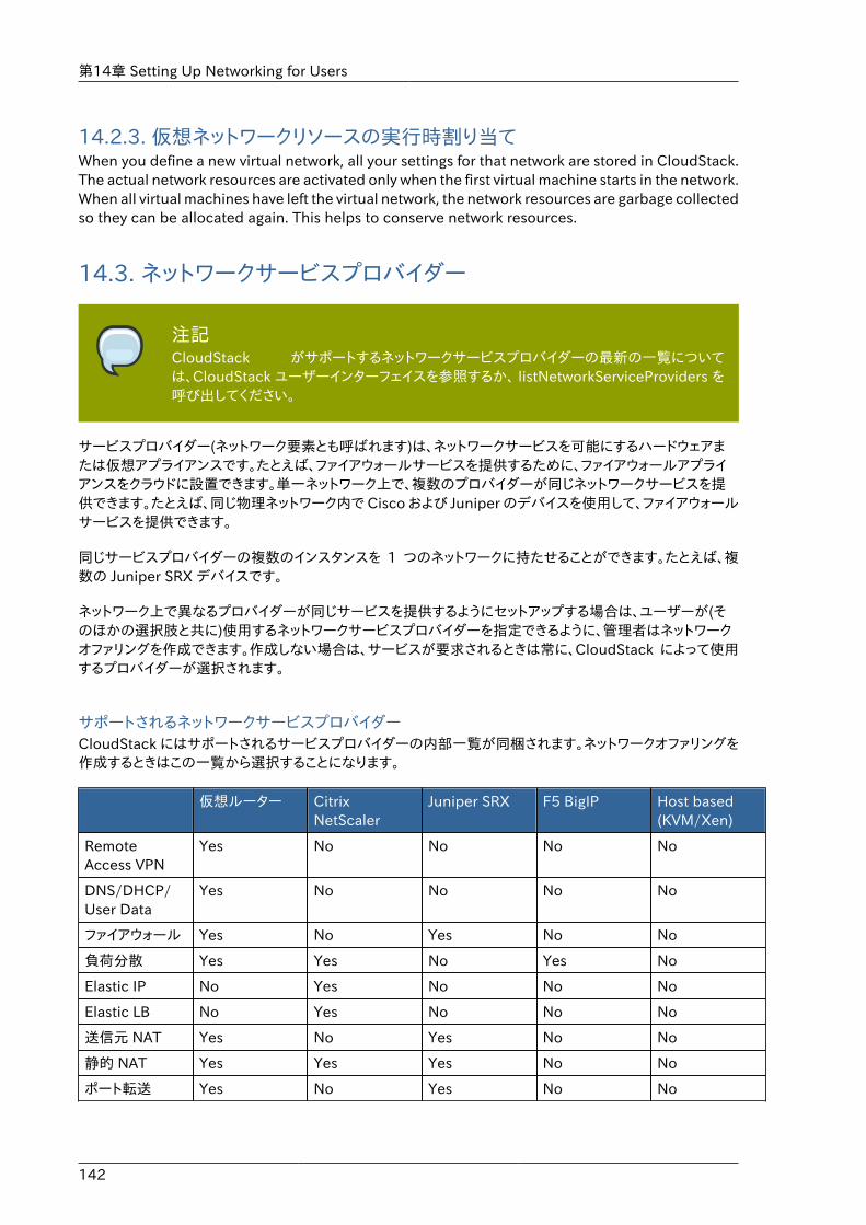
第14章 Setting Up Networking for Users
142
14.2.3. 仮想ネットワークリソースの実行時割り当てWhen you define a new virtual network, all your settings for that network are stored in CloudStack.The actual network resources are activated only when the first virtual machine starts in the network.When all virtual machines have left the virtual network, the network resources are garbage collectedso they can be allocated again. This helps to conserve network resources.
14.3. ネットワークサービスプロバイダー
注記CloudStack がサポートするネットワークサービスプロバイダーの最新の一覧については、CloudStack ユーザーインターフェイスを参照するか、 listNetworkServiceProviders を呼び出してください。
サービスプロバイダー(ネットワーク要素とも呼ばれます)は、ネットワークサービスを可能にするハードウェアまたは仮想アプライアンスです。たとえば、ファイアウォールサービスを提供するために、ファイアウォールアプライアンスをクラウドに設置できます。単一ネットワーク上で、複数のプロバイダーが同じネットワークサービスを提供できます。たとえば、同じ物理ネットワーク内で Cisco および Juniper のデバイスを使用して、ファイアウォールサービスを提供できます。
同じサービスプロバイダーの複数のインスタンスを 1 つのネットワークに持たせることができます。たとえば、複数の Juniper SRX デバイスです。
ネットワーク上で異なるプロバイダーが同じサービスを提供するようにセットアップする場合は、ユーザーが(そのほかの選択肢と共に)使用するネットワークサービスプロバイダーを指定できるように、管理者はネットワークオファリングを作成できます。作成しない場合は、サービスが要求されるときは常に、CloudStack によって使用するプロバイダーが選択されます。
サポートされるネットワークサービスプロバイダーCloudStack にはサポートされるサービスプロバイダーの内部一覧が同梱されます。ネットワークオファリングを作成するときはこの一覧から選択することになります。
仮想ルーター CitrixNetScaler
Juniper SRX F5 BigIP Host based(KVM/Xen)
RemoteAccess VPN
Yes No No No No
DNS/DHCP/User Data
Yes No No No No
ファイアウォール Yes No Yes No No
負荷分散 Yes Yes No Yes No
Elastic IP No Yes No No No
Elastic LB No Yes No No No
送信元 NAT Yes No Yes No No
静的 NAT Yes Yes Yes No No
ポート転送 Yes No Yes No No
ネットワークオファリング
143
14.4. ネットワークオファリング
注記サポートされるネットワークサービスのリストに関するアップデートは CloudStack ユーザーインターフェイスか listNetworkServices の呼び出し結果を参照してください。
ネットワークオファリングは、次のようなネットワークサービスのセットに名前を付けたものです。
• DHCP
• DNS
• 送信元 NAT
• 静的 NAT
• ポート転送
• 負荷分散
• ファイアウォール
• VPN
• (オプション)ファイアウォール向けに Juniper など、特定のサービスに使用する、使用可能なプロバイダーのいずれかの名前
• (オプション)使用する物理ネットワークを指定するネットワークタグ
新しい仮想マシンの作成時に、ユーザーは使用できるネットワークオファリングの中から 1 つ選択します。これで仮想マシンで使用できるネットワークサービスが決定します。
CloudStack 管理者は、CloudStack によって提供されるデフォルトのネットワークオファリングのほかに、カスタムネットワークオファリングをいくつでも作成できます。複数のカスタムネットワークオファリングを作成することによって、単一のマルチテナント物理ネットワーク上でさまざまなクラスのサービスを提供するようにクラウドをセットアップできます。 たとえば、基になる物理的な有線接続は同じであっても、テナント A に は Web サイト用に単純なファイアウォールの保護のみを提供し、テナント B にはデータベースのバックエンドにアクセスするために、Web サー バーファームを運用し、スケーラブルなファイアウォールソリューション、 負荷分散ソリューション、および代替ネットワークを提供することができ ます。
注記もし、負荷分散ルールを作成する際 NetScaler のような外部デバイスを含んだネットワークサービスオファリングを利用していた場合、また後にネットワークサービスオファリングをCloudStack の仮想ルーターを利用するよう変更を加える場合、継続して機能を利用するためには全ての負荷分散ルールに対しファイアウォールルールを追加しなければなりません。
新しい仮想ネットワークを作成するとき、CloudStack 管理者はそのネッ トワークに対して有効にするネットワークオファリングを選択します。各\n仮想ネットワークは、1 つのネットワークオファリングに関連付けられます。仮想ネットワークは、その関連付けられたネットワークオファリングを変更することによって、アップグレードしたりダウングレードしたりできます。そうする場合は、合致する物理ネットワークを再プログラミングしてください。
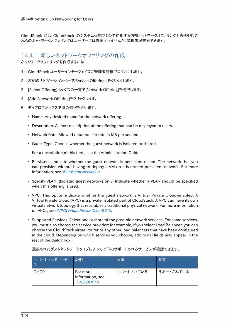
第14章 Setting Up Networking for Users
144
CloudStack には、CloudStack のシステム仮想マシンで使用する内部ネットワークオファリングもあります。これらのネットワークオファリングはユーザーには表示されませんが、管理者が変更できます。
14.4.1. 新しいネットワークオファリングの作成ネットワークオファリングを作成するには
1. CloudStack ユーザーインターフェイスに管理者特権でログオンします。
2. 左側のナビゲーションバーで[Service Offerings]をクリックします。
3. [Select Offering]ボックスの一覧で[Network Offering]を選択します。
4. [Add Network Offering]をクリックします。
5. ダイアログボックスで次の選択を行います。
• Name. Any desired name for the network offering.
• Description. A short description of the offering that can be displayed to users.
• Network Rate. Allowed data transfer rate in MB per second.
• Guest Type. Choose whether the guest network is isolated or shared.
For a description of this term, see the Administration Guide.
• Persistent. Indicate whether the guest network is persistent or not. The network that youcan provision without having to deploy a VM on it is termed persistent network. For moreinformation, see �Persistent Networks�.
• Specify VLAN. (Isolated guest networks only) Indicate whether a VLAN should be specifiedwhen this offering is used.
• VPC. This option indicate whether the guest network is Virtual Private Cloud-enabled. AVirtual Private Cloud (VPC) is a private, isolated part of CloudStack. A VPC can have its ownvirtual network topology that resembles a traditional physical network. For more informationon VPCs, see �VPC(Virtual Private Cloud) ����.
• Supported Services. Select one or more of the possible network services. For some services,you must also choose the service provider; for example, if you select Load Balancer, you canchoose the CloudStack virtual router or any other load balancers that have been configuredin the cloud. Depending on which services you choose, additional fields may appear in therest of the dialog box.
選択されたゲストネットワークタイプによって以下のサポートされるサービスが確認できます。
サポートされるサービス
説明 分離 共有
DHCP For moreinformation, see�DNS�DHCP�.
サポートされている サポートされている
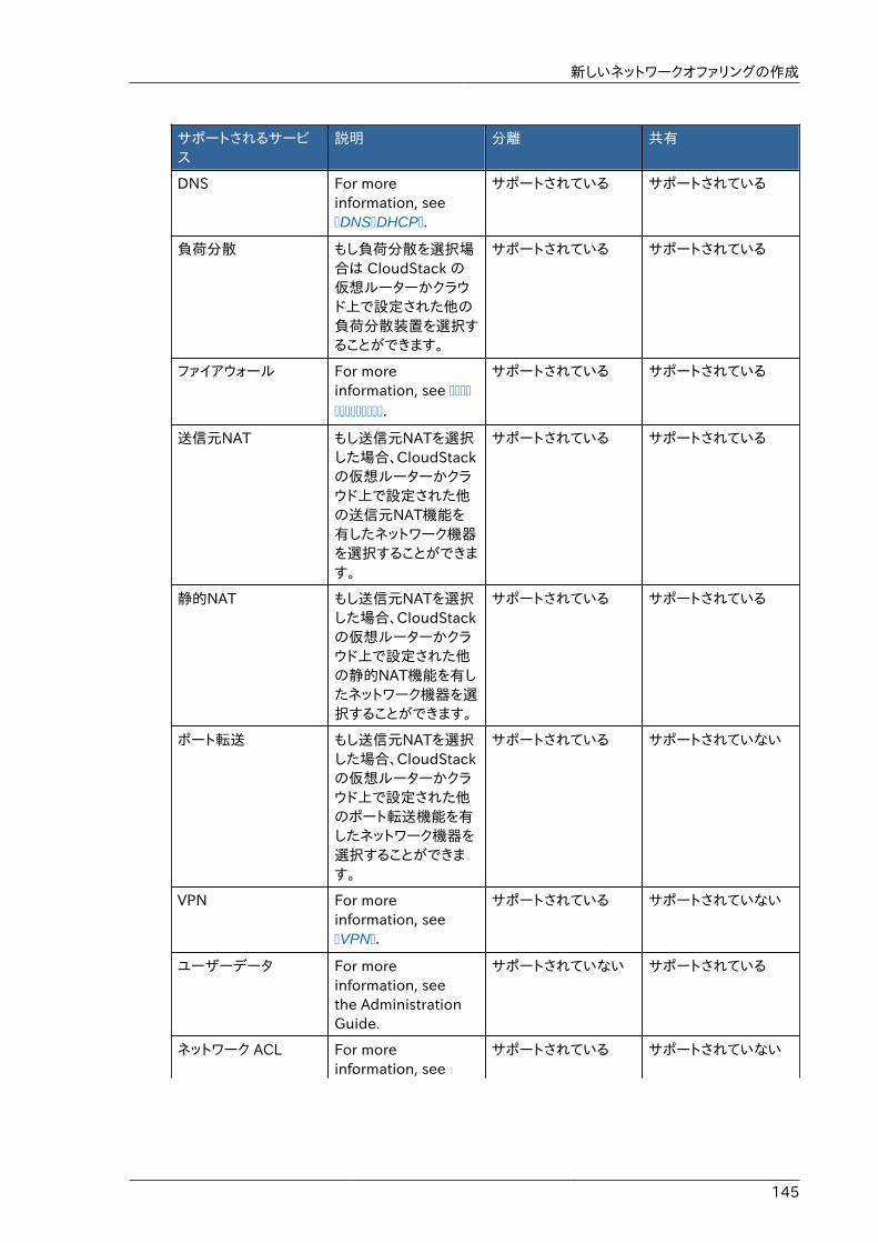
新しいネットワークオファリングの作成
145
サポートされるサービス
説明 分離 共有
DNS For moreinformation, see�DNS�DHCP�.
サポートされている サポートされている
負荷分散 もし負荷分散を選択場合は CloudStack の仮想ルーターかクラウド上で設定された他の負荷分散装置を選択することができます。
サポートされている サポートされている
ファイアウォール For moreinformation, see �������������.
サポートされている サポートされている
送信元NAT もし送信元NATを選択した場合、CloudStackの仮想ルーターかクラウド上で設定された他の送信元NAT機能を有したネットワーク機器を選択することができます。
サポートされている サポートされている
静的NAT もし送信元NATを選択した場合、CloudStackの仮想ルーターかクラウド上で設定された他の静的NAT機能を有したネットワーク機器を選択することができます。
サポートされている サポートされている
ポート転送 もし送信元NATを選択した場合、CloudStackの仮想ルーターかクラウド上で設定された他のポート転送機能を有したネットワーク機器を選択することができます。
サポートされている サポートされていない
VPN For moreinformation, see�VPN�.
サポートされている サポートされていない
ユーザーデータ For moreinformation, seethe AdministrationGuide.
サポートされていない サポートされている
ネットワーク ACL For moreinformation, see
サポートされている サポートされていない
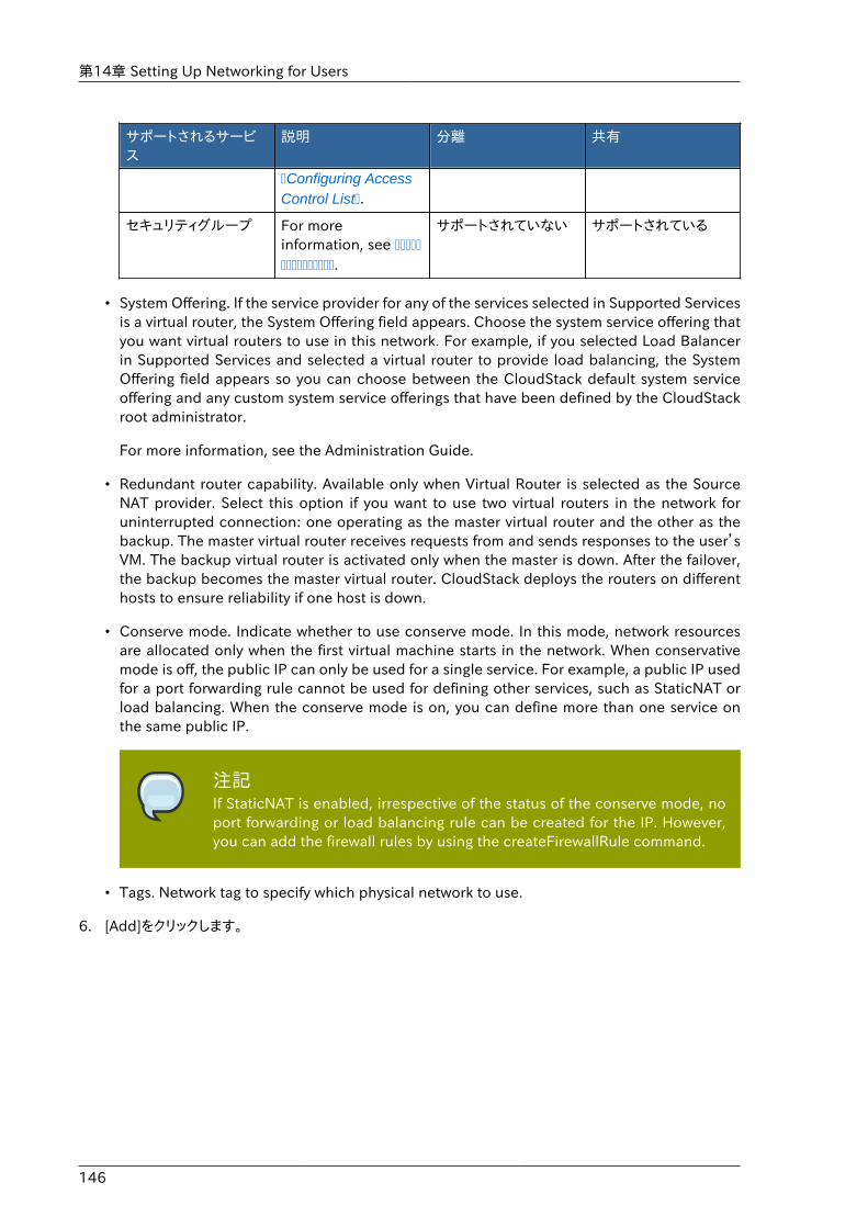
第14章 Setting Up Networking for Users
146
サポートされるサービス
説明 分離 共有
�Configuring AccessControl List�.
セキュリティグループ For moreinformation, see ���������������.
サポートされていない サポートされている
• System Offering. If the service provider for any of the services selected in Supported Servicesis a virtual router, the System Offering field appears. Choose the system service offering thatyou want virtual routers to use in this network. For example, if you selected Load Balancerin Supported Services and selected a virtual router to provide load balancing, the SystemOffering field appears so you can choose between the CloudStack default system serviceoffering and any custom system service offerings that have been defined by the CloudStackroot administrator.
For more information, see the Administration Guide.
• Redundant router capability. Available only when Virtual Router is selected as the SourceNAT provider. Select this option if you want to use two virtual routers in the network foruninterrupted connection: one operating as the master virtual router and the other as thebackup. The master virtual router receives requests from and sends responses to the user’sVM. The backup virtual router is activated only when the master is down. After the failover,the backup becomes the master virtual router. CloudStack deploys the routers on differenthosts to ensure reliability if one host is down.
• Conserve mode. Indicate whether to use conserve mode. In this mode, network resourcesare allocated only when the first virtual machine starts in the network. When conservativemode is off, the public IP can only be used for a single service. For example, a public IP usedfor a port forwarding rule cannot be used for defining other services, such as StaticNAT orload balancing. When the conserve mode is on, you can define more than one service onthe same public IP.
注記If StaticNAT is enabled, irrespective of the status of the conserve mode, noport forwarding or load balancing rule can be created for the IP. However,you can add the firewall rules by using the createFirewallRule command.
• Tags. Network tag to specify which physical network to use.
6. [Add]をクリックします。
147
仮想マシンの操作
15.1. 仮想マシンの操作CloudStackでは、クラウドで実行するすべてのゲスト仮想マシンのライフサイクルを管理者が完全に制御できます。CloudStackには、エンドユーザー用および管理者用のゲスト管理操作が複数用意されています。仮想マシンは、停止、開始、再起動、および破棄することができます。
ゲストには名前とグループがあります。ゲスト名とグループはCloudStackにとって曖昧な情報で、エンドユーザーが自分の仮想マシンを整理するために使用できます。各仮想マシンには、異なるコンテキストで使用する3つの名前があります。これらの名前のうち、ユーザーが制御できるのは2つだけです。
• Instance name – a unique, immutable ID that is generated by CloudStack, and can not bemodified by the user. This name conforms to the requirements in IETF RFC 1123.
• Display name – the name displayed in the CloudStack web UI. Can be set by the user. Defaultsto instance name.
• Name – host name that the DHCP server assigns to the VM. Can be set by the user. Defaults toinstance name
ゲストはHA(Highly Available:高可用性を持つ)に構成できます。HAが有効なゲストはシステムによって監視されます。ゲストがダウン状態であることが検出されると、場合によっては別のホスト上でゲストの再起動が試行されます。
新しく作成したVMには、各々1つのパブリックIPアドレスが割り当たります。VMを起動するとき、CloudStack は自動的にパブリックIPアドレスとプライベートIPアドレスの間で静的NATを設定します。
エラスティックIPを(NetScaler負荷分散装置と共に)使用する場合、新たに作成するVMはエラスティックとして初期設定されません。ユーザーは自動設定されたIPを明示的に取得したエラスティックIPに置き換え、静的NATのマッピングを新しいIPとVMのプライベートIPに対して行う必要があります。その際、VMの元のIPアドレスは解放され、利用可能なパブリックIPのプールに返却されます。
CloudStackプラットフォームでは、予期せずに終了した仮想マシンと、ユーザーによって(たとえば、Linuxのshutdownコマンドで)シャットダウンされたゲスト仮想マシンを区別できません。HAが有効なゲストが仮想マシン内部でシャットダウンされた場合、CloudStackプラットフォームによってそのゲストが再起動されます。HAが有効なゲストをシャットダウンするには、ユーザーはCloudStackユーザーインターフェイスまたはAPIを使用する必要があります。
15.2. Best Practices for Virtual MachinesThe CloudStack administrator should monitor the total number of VM instances in each cluster,and disable allocation to the cluster if the total is approaching the maximum that the hypervisorcan handle. Be sure to leave a safety margin to allow for the possibility of one or more hosts failing,which would increase the VM load on the other hosts as the VMs are automatically redeployed.Consult the documentation for your chosen hypervisor to find the maximum permitted number ofVMs per host, then use CloudStack global configuration settings to set this as the default limit.Monitor the VM activity in each cluster at all times. Keep the total number of VMs below a safelevel that allows for the occasional host failure. For example, if there are N hosts in the cluster, andyou want to allow for one host in the cluster to be down at any given time, the total number of VMinstances you can permit in the cluster is at most (N-1) * (per-host-limit). Once a cluster reachesthis number of VMs, use the CloudStack UI to disable allocation of more VMs to the cluster.
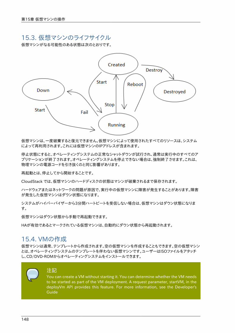
第15章 仮想マシンの操作
148
15.3. 仮想マシンのライフサイクル仮想マシンがなる可能性のある状態は次のとおりです。
仮想マシンは、一度破棄すると復元できません。仮想マシンによって使用されたすべてのリソースは、システムによって再利用されます。これには仮想マシンのIPアドレスが含まれます。
停止状態にすると、オペレーティングシステムの正常なシャットダウンが試行され、通常は実行中のすべてのアプリケーションが終了されます。オペレーティングシステムを停止できない場合は、強制終了させます。これは、物理マシンの電源コードを引き抜くのと同じ影響があります。
再起動とは、停止してから開始することです。
CloudStack では、仮想マシンのハードディスクの状態はマシンが破棄されるまで保存されます。
ハードウェアまたはネットワークの問題が原因で、実行中の仮想マシンに障害が発生することがあります。障害が発生した仮想マシンはダウン状態になります。
システムがハイパーバイザーから3分間ハートビートを受信しない場合は、仮想マシンはダウン状態になります。
仮想マシンはダウン状態から手動で再起動できます。
HAが有効であるとマークされている仮想マシンは、自動的にダウン状態から再起動されます。
15.4. VMの作成仮想マシンは通常、テンプレートから作成されます。空の仮想マシンを作成することもできます。空の仮想マシンとは、オペレーティングシステムのテンプレートを伴わない仮想マシンです。ユーザーはISOファイルをアタッチし、CD/DVD-ROMからオペレーティングシステムをインストールできます。
注記You can create a VM without starting it. You can determine whether the VM needsto be started as part of the VM deployment. A request parameter, startVM, in thedeployVm API provides this feature. For more information, see the Developer'sGuide
仮想マシンへのアクセス
149
テンプレートから仮想マシンを作成するには
1. 管理者またはユーザーとしてCloudStackユーザーインターフェイスにログオンします。
2. 左側のナビゲーションバーで[Instances]をクリックします。
3. [Add Instance]をクリックします。
4. ゾーンの選択
5. テンプレートを選択して、ウィザードの手順に従います。テンプレートを一覧に表示する方法の詳細ついては、17����������を参照してください。
6. 使用するハードウェアで、選択したサービスオファリングを開始できることを確認してください。
7. [Submit]をクリックし、仮想マシンを作成して開始します。
注記セキュリティ上の理由から、内部の仮想マシン名は root 管理者のみ閲覧できます。
ISOから仮想マシンを作成するには
注記(XenServer) Windows 仮想マシンを XenServer 上で動作させるにはテンプレートとして提供するか仮想マシンの作成後に追加する PV ドライバーが必要となります。管理サーバーでの追加ボリュームやISOイメージのマウント、ライブマイグレーション、グレースフルシャットダウンといった機能を利用するには PV ドライバーは必須となります。
1. 管理者またはユーザーとしてCloudStackユーザーインターフェイスにログオンします。
2. 左側のナビゲーションバーで[Instances]をクリックします。
3. [Add Instance]をクリックします。
4. ゾーンの選択
5. [ISO Boot]を選択し、ウィザードの手順に従います。
6. [Submit]をクリックし、仮想マシンを作成して開始します。
15.5. 仮想マシンへのアクセス各ユーザーはそれぞれの仮想マシンにアクセスすることができます。また、管理者はクラウド上の起動中の全ての仮想マシンにアクセスすることができます。
CloudStack UIからの仮想マシンへのアクセス
1. ユーザーもしくは管理者として CloudStack UIからログインします。
2. インスタンスをクリックし、起動中の仮想マシンの名前をクリックします。
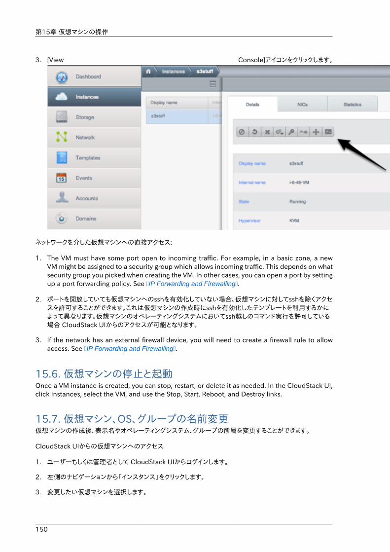
第15章 仮想マシンの操作
150
3. [View Console]アイコンをクリックします。
.
ネットワークを介した仮想マシンへの直接アクセス:
1. The VM must have some port open to incoming traffic. For example, in a basic zone, a newVM might be assigned to a security group which allows incoming traffic. This depends on whatsecurity group you picked when creating the VM. In other cases, you can open a port by settingup a port forwarding policy. See �IP Forwarding and Firewalling�.
2. ポートを開放していても仮想マシンへのsshを有効化していない場合、仮想マシンに対してsshを除くアクセスを許可することができます。これは仮想マシンの作成時にsshを有効化したテンプレートを利用するかによって異なります。仮想マシンのオペレーティングシステムにおいてssh越しのコマンド実行を許可している場合 CloudStack UIからのアクセスが可能となります。
3. If the network has an external firewall device, you will need to create a firewall rule to allowaccess. See �IP Forwarding and Firewalling�.
15.6. 仮想マシンの停止と起動Once a VM instance is created, you can stop, restart, or delete it as needed. In the CloudStack UI,click Instances, select the VM, and use the Stop, Start, Reboot, and Destroy links.
15.7. 仮想マシン、OS、グループの名前変更仮想マシンの作成後、表示名やオペレーティングシステム、グループの所属を変更することができます。
CloudStack UIからの仮想マシンへのアクセス
1. ユーザーもしくは管理者として CloudStack UIからログインします。
2. 左側のナビゲーションから「インスタンス」をクリックします。
3. 変更したい仮想マシンを選択します。
仮想マシンのサービスオファリングの変更
151
4.Click the Stop button to stop the VM.
5.Click Edit.
6. 変更したい以下項目の確認:
7. Display name: Enter a new display name if you want to change the name of the VM.
8. OS Type: Select the desired operating system.
9. Group: Enter the group name for the VM.
10. 「適用」をクリックします。
15.8. 仮想マシンのサービスオファリングの変更To upgrade or downgrade the level of compute resources available to a virtual machine, you canchange the VM's compute offering.
1. ユーザーもしくは管理者として CloudStack UIからログインします。
2. 左側のナビゲーションから「インスタンス」をクリックします。
3. 削除したい仮想マシンを選択します。
4.Click the Stop button to stop the VM.
5.Click the Change Service button.
The Change service dialog box is displayed.
6. Select the offering you want to apply to the selected VM.
7. 「OK」をクリックします。
15.9. ホスト間の仮想マシンの移動(手動ライブマイグレーション)CloudStack管理者は、ユーザーへのサービスを中断させることも、保守モードにすることもなく、実行中の仮想マシンをあるホストから別のホストに移動できます。これを手動ライブマイグレーションと呼び、次の条件で実行できます。
• ルート管理者がログオンしていること。ドメイン管理者およびユーザーは仮想マシンの手動ライブマイグレーションを実行できません。
• 仮想マシンが実行中であること。停止中の仮想マシンはライブマイグレーションできません。
• 移行先ホストが移行元のホストと同じクラスターに存在すること。
• 仮想マシンがローカルディスクストレージを使用していないこと。
• The destination host must have enough available capacity. If not, the VM will remain in the"migrating" state until memory becomes available.
第15章 仮想マシンの操作
152
仮想マシンを手動でライブマイグレーションするには
1. ユーザーもしくは管理者として CloudStack UIからログインします。
2. 左側のナビゲーションから「インスタンス」をクリックします。
3. 移行する仮想マシンを選択します。
4.[Migrate Instance] ボタンをクリックします。
5. ホストの一覧から仮想マシンの移行先を選択します。
6. [OK]をクリックします。
15.10. 仮想マシンの削除ユーザーは独自の仮想マシンを削除でき、起動中の仮想マシンの場合は削除前に停止されます。管理者は全ての仮想マシンを削除することができます。
仮想マシンの削除方法:
1. ユーザーもしくは管理者として CloudStack UIからログインします。
2. 左側のナビゲーションから [Instances] をクリックします。
3. 削除したい仮想マシンを選択します。
4.[Destroy Instance]アイコンをクリックします。
15.11. ISO に関わる作業CloudStack は、ISO および ISO のゲスト仮想マシンへのアタッチをサポートします。ISO は、ISO/CD-ROM形式のファイルシステムの読み取り専用ファイルです。ユーザーは自分の ISO をアップロードして、自分のゲスト仮想マシンにマウントできます。
ISO は、URL に基づいてアップロードされます。サポートされるプロトコルは HTTP です。ISO が HTTP 経由で利用できるようになったら、http://my.web.server/filename.iso のようなアップロード用の URL を指定します。
テンプレートのように、ISO をパブリックまたはプライベートにすることができます。ISO はハイパーバイザー固有ではありません。つまり、vSphere のゲストは、KVM のゲストがマウントできるのとまったく同じイメージをマウントできます。
ISO イメージは、システムに格納して、テンプレートと同様のプライバシーレベルを指定して使用することができます。ISO イメージは、起動可能または起動不可に分類されます。起動可能な ISO イメージは、オペレーティングシステムイメージを含むものです。CloudStack では、ユーザーが ISO イメージからゲスト仮想マシンを起動することができます。また、ユーザーは ISO イメージをゲスト仮想マシンにアタッチすることもできます。たとえば、これにより PV ドライバーを Windows にインストールできます。ISO イメージは、ハイパーバイザー固有ではありませ ん。
15.11.1. ISO の追加追加のオペレーティングシステムやほかのソフトウェアをゲスト仮想マシンで使用できるようにするために、ISOを追加できます。ISO は通常、オペレーティングシステムのイメージと考えられていますが、テンプレートの一部と
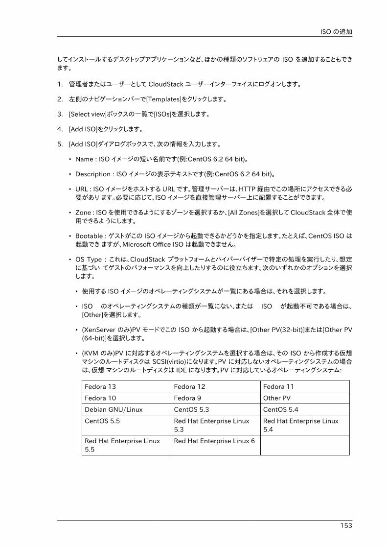
ISO の追加
153
してインストールするデスクトップアプリケーションなど、ほかの種類のソフトウェアの ISO を追加することもできます。
1. 管理者またはユーザーとして CloudStack ユーザーインターフェイスにログオンします。
2. 左側のナビゲーションバーで[Templates]をクリックします。
3. [Select view]ボックスの一覧で[ISOs]を選択します。
4. [Add ISO]をクリックします。
5. [Add ISO]ダイアログボックスで、次の情報を入力します。
• Name : ISO イメージの短い名前です(例:CentOS 6.2 64 bit)。
• Description : ISO イメージの表示テキストです(例:CentOS 6.2 64 bit)。
• URL : ISO イメージをホストする URL です。管理サーバーは、HTTP 経由でこの場所にアクセスできる必要があり ます。必要に応じて、ISO イメージを直接管理サーバー上に配置することができます。
• Zone : ISO を使用できるようにするゾーンを選択するか、[All Zones]を選択して CloudStack 全体で使用できるよ うにします。
• Bootable : ゲストがこの ISO イメージから起動できるかどうかを指定します。たとえば、CentOS ISO は起動でき ますが、Microsoft Office ISO は起動できません。
• OS Type : これは、CloudStack プラットフォームとハイパーバイザーで特定の処理を実行したり、想定に基づい てゲストのパフォーマンスを向上したりするのに役立ちます。次のいずれかのオプションを選択します。
• 使用する ISO イメージのオペレーティングシステムが一覧にある場合は、それを選択します。
• ISO のオペレーティングシステムの種類が一覧にない、または ISO が起動不可である場合は、[Other]を選択します。
• (XenServer のみ)PV モードでこの ISO から起動する場合は、[Other PV(32-bit)]または[Other PV(64-bit)]を選択します。
• (KVM のみ)PV に対応するオペレーティングシステムを選択する場合は、その ISO から作成する仮想マシンのルートディスクは SCSI(virtio)になります。PV に対応しないオペレーティングシステムの場合は、仮想 マシンのルートディスクは IDE になります。PV に対応しているオペレーティングシステム:
Fedora 13 Fedora 12 Fedora 11
Fedora 10 Fedora 9 Other PV
Debian GNU/Linux CentOS 5.3 CentOS 5.4
CentOS 5.5 Red Hat Enterprise Linux5.3
Red Hat Enterprise Linux5.4
Red Hat Enterprise Linux5.5
Red Hat Enterprise Linux 6
第15章 仮想マシンの操作
154
注記注:通常は、イメージのオペレーティングシステムより古いバージョンを選択しないでください。たとえば、\nCentOS 6.2 イメージをサポートするために CentOS 5.4 を選択すると、通常は動作しません。このような場合は、 [Other]を選択する必要があります。
• Extractable : ISO が抽出可能である必要がある場合は、このチェックボックスをオンにします。
• Public : この ISO をほかのユーザーが使用できる必要がある場合は、このチェックボックスをオンにします。
• Featured : ユーザーが ISO を選択するときに「おすすめの ISO」としてこの ISO を目立たせるには、このチェック ボックスをオンにします。ISO が[Featured ISOs]の一覧に表示されます。ISO をおすすめに設定できるのは管理者だけです。
6. 「OK」をクリックします。
管理サーバーが ISO をダウンロードします。ISO のサイズによっては、しばらく時間がかかることがあります。ISO が セカンダリストレージに正常にダウンロードされると、ISO の状態が準備完了になります。[Refresh]をクリックすると、 ダウンロードの進捗率が更新されます。
7. 重要 : ISO のダウンロードが完了するまで次の操作をしないでください。次のタスクに進んで ISO をすぐ使用しようとすると、失敗します。CloudStack で ISO 全体を利用できるようになってから、操作する必要があります。
15.11.2. 仮想マシンへのISOのアタッチ1. 左側のナビゲーションから「インスタンス」をクリックします。
2. アタッチする仮想マシンの選択
3.[Attach ISO]ボタンをクリックします。
4. ISOアタッチのダイアログボックスで、アタッチしたいISOを選択します。
5. [OK]をクリックします。
155
ホストの操作
16.1. ホストの追加ゲスト仮想マシンの処理能力を上げるため、いつでもホストを追加できます。要件と手順については、��������を参照してください。
16.2. ホストの計画保守と保守モードホストを保守モードにすることができます。保守モードがアクティブになると、ホストで新しいゲスト仮想マシンを処理できな くなります。そのホストで実行中のゲスト仮想マシンは、保守モードでない別のホストにシームレスに移行されます。この移行にはライブマイグレーション技術が使用され、ゲストの実行が中断されることはありません。
16.2.1. vCenter と保守モードvCenter ホストで保守モードを開始するには、vCenter と CloudStack が互いに連携して動作する必要があります。 CloudStack と vCenter には、緊密に連携する別々の保守モードがあります。
1. Place the host into CloudStack's "scheduled maintenance" mode. This does not invoke thevCenter maintenance mode, but only causes VMs to be migrated off the host
CloudStack の保守モードが要求されると、まずホストは保守準備状態になります。この状態のホストは、新しいゲスト仮想マシンの起動対象になりません。次に、すべての仮想マシンがサーバーから移行されます。ライブマイグレーションを使用して、ホストから仮想マシンを移動します。これにより、ゲストの中断を伴わずに、ほかのホストにゲストを移行できます。この移行の完了後、ホストは保守準備完了モードになります。
2. Wait for the "Ready for Maintenance" indicator to appear in the UI.
3. ここで vCenter を使用して、ホストの保守に必要な操作を実行します。この間、ホストは新しいゲスト仮想マシンの割り当て対象になりません。
4. 保守タスクを完了したら、次のようにホストの保守モードを解除します。
a. まず vCenter を使用して、vCenter の保守モードを終了します。
これにより、CloudStack による再アクティブ化の準備がホスト側で整います。
b. Then use CloudStack's administrator UI to cancel the CloudStack maintenance mode
ホストがオンラインに戻ると、ホストから移行されていた仮想マシンがホストに戻り、新しい仮想マシンを追加で きるようになります。
16.2.2. XenServer と保守モードXenServer では XenCenter の保守モード機能を使うことで一時的にサーバーをオフラインにできます。サーバーを保守モードにした場合、全ての稼働中仮想マシンは自動的に同じプール上の別ホストにマイグレーションされます。サーバーがプールのマスターである場合、プールから新しいマスターが選出されます。サーバーが保守モード中は仮想マシンの作成や起動はできません。
サーバーを保守モードにするには:
第16章 ホストの操作
156
1. [Resources]ペインからサーバーを選択し以下の作業を実施します。
• 右クリックしてショートカットメニューから[Enter Maintenance Mode]をクリックします。
• On the Server menu, click Enter Maintenance Mode.
2. Click Enter Maintenance Mode.
The server's status in the Resources pane shows when all running VMs have been successfullymigrated off the server.
サーバーを保守モードから戻すには:
1. [Resources]ペインからサーバーを選択し以下の作業を実施します。
• 右クリックしてショートカットメニューから[Exit Maintenance Mode]をクリックします。
• On the Server menu, click Exit Maintenance Mode.
2. Click Exit Maintenance Mode.
16.3. ゾーン、ポッド、およびクラスターの無効化と有効化ゾーン、ポッド、またはクラスターは、クラウドから完全に削除することなく、有効または無効にできます。これは、保守のため、または問題が発生してクラウドインフラストラクチャの一部が信頼できなくなった場合に便利です。状態が有効に戻るまで、無効のゾーン、ポッド、またはクラスターに新しい割り当ては行われません。最初にゾーン、ポッド、またはクラスターがクラウドに追加されたときはデフォルトで無効になっています。
ゾーン、ポッド、またはクラスターを無効または有効にするには
1. CloudStack ユーザーインターフェイスに管理者としてログオンします。
2. 左側のナビゲーションバーで [Infrastructure] をクリックします。
3. [Zones] で [View More]をクリックします。
4. ゾーンを有効化、無効化する場合はゾーンの名前をリストから探して [Enable/Disable] ボタンをクリックし
てください。
5. ポッドまたはクラスターを無効または有効にするには、そのポッドまたはクラスターを含むゾーンの名前をクリックし ます。
6. [Compute] タブをクリックします。
7. ダイアグラムの [Pods] または [Clusters] ノードの [View All] をクリックします。
8. 一覧内のポッドまたはクラスターをクリックします。
9.[Enable] または [Disable] アイコンをクリックします。
16.4. ホストの削除ホストは必要に応じてクラウドから削除できます。ホストを削除する手順は、ハイパーバイザーの種類によって異なりま す。
XenServer および KVM ホストの削除
157
16.4.1. XenServer および KVM ホストの削除ノードは、保守モードになるまでクラスターから削除できません。これによって、ノード上のすべての仮想マシンがほかのホストに確実に移行されます。ホストをクラウドから削除するには、次の手順に従います。
1. ノードを保守モードにします。
���������������� を参照してください。
2. For KVM, stop the cloudstack-agent service.
3. ユーザーインターフェイスオプションを使用して、ノードを削除します。
これで、ホストの電源を切り、その IP アドレスを再使用したり再インストールしたりできるようになりました。
16.4.2. vSphere ホストの削除この種類のホストを削除するには、���������������� で説明されているように、まずホストを保守モードにします。次に、CloudStack を使用して、ホストを削除します。CloudStack を使用して削除されたホストに対して、CloudStack はコマンドを実行しません。ただし、その場合でもホストは vCenter クラスター内に残しておくことができます。
16.5. Re-Installing HostsYou can re-install a host after placing it in maintenance mode and then removing it. If a host isdown and cannot be placed in maintenance mode, it should still be removed before the re-install.
16.6. ハイパーバイザーホストの維持ハイパーバイザーソフトウェアをホスト上で動作させている場合、ハイパーバイザー製造元が提供するすべてのHotfix を適用したことを確認します。ハイパーバイザーの製造元のサポートチャ ネルを通じてパッチのリリース状況を確認し、パッチがリリースさ れたらできるだけ早く適用します。ハイパーバイザーの必須パッチについてCloudStack が自動的に通知することはありません。 ホストにハイパーバイザーの最新パッチを適用することは非常に 重要です。最新パッチが適用されていないシステムは、おそらくハイパーバイザーの製造元からサポートを受けられません。
注記最新の Hotfix を適用しないと、データの破損や仮想マシンの喪失が生じる可能性があります。
(XenServer) For more information, see Highly Recommended Hotfixes for XenServer in the CloudStackKnowledge Base1.
16.7. Changing Host PasswordThe password for a XenServer Node, KVM Node, or vSphere Node may be changed in the database.Note that all Nodes in a Cluster must have the same password.
To change a Node's password:
1 http://docs.cloudstack.org/Knowledge_Base/Possible_VM_corruption_if_XenServer_Hotfix_is_not_Applied/Highly_Recommended_Hotfixes_for_XenServer_5.6_SP2
第16章 ホストの操作
158
1. Identify all hosts in the cluster.
2. Change the password on all hosts in the cluster. Now the password for the host and thepassword known to CloudStack will not match. Operations on the cluster will fail until the twopasswords match.
3. Get the list of host IDs for the host in the cluster where you are changing the password. You willneed to access the database to determine these host IDs. For each hostname "h" (or vSpherecluster) that you are changing the password for, execute:
mysql> select id from cloud.host where name like '%h%';
4. This should return a single ID. Record the set of such IDs for these hosts.
5. Update the passwords for the host in the database. In this example, we change the passwordsfor hosts with IDs 5, 10, and 12 to "password".
mysql> update cloud.host set password='password' where id=5 or id=10 or id=12;
16.8. ホストの割り当てシステムは仮想マシンを動作させるために最も適切なホストを自動的に選択します。エンドユーザーは仮想マシンを作成するゾーンを指定することができますが仮想マシンインスタンスがどのホストで動作するかは制御することはできません。
CloudStack 管理者はゲストインスタンタイプに対しパフォーマンスを確保するため特定のホストを指定することができます。たとえば管理者は Windows ゲストを動作させるだけのパフォーマンスを確保するためにホストを指定することができます。デフォルトのホスト割り当ては OS タイプによりどのホストに配置するかを試み、動作可能な処理能力を持つサーバー全てが対象になります。
垂直割り当てと水平割り当ての両方が可能です。垂直割り当てでは、特定のホストのリソースをすべて消費した後で、次のホストにゲストを割り当てます。これにより、クラウドの消費電力が抑えられます。水平割り当てでは、ラウンドロビン方式で各ホストにゲストを配置します。これにより、ゲストのパフォーマンスが向上する場合があります。CloudStack では、管理者が構成するとおりに CPU オーバープロビジョニングの要素を許可することができます。オーバープロビジョニングを使用すると、ハードウェアで実際に使用できるよりも高い CPU サイクルをゲストに割り当てることができま す。
また、CloudStack では、新しいアロケーターを追加するためのプラグ可能なインターフェイスも提供します。 これらのカスタムアロケーターを使用して、管理者が要求するどのようなポリシーにも対応できます。
16.8.1. オーバープロビジョニングとサービスオファリングの制限CloudStack では、管理者の構成するオーバープロビジョニング比率に基づいて、CPU オーバープロビジョニングを実行します。これは、「cpu.overprovisioning.factor」 グローバル構成変数によって定義されます。
CloudStack では、管理者の構成するオーバープロビジョニング比率に基づいて、CPU オーバープロビジョニングを実行します。これは、「cpu.overprovisioning.factor」 グローバル構成変数によって定義されます。
サービスオファリングの制限(たとえば、1GHz、1 コアなど)は、コア数に厳密に適用されます。たとえば、1 コアを提供するサービスオファリングを使用するゲストは、ホスト上のほかのアクティビティにかかわりなく、使用できるコアは 1 つだけで す。
動作周波数に対するサービスオファリングの制限は、CPU リソースが競合する場合にのみ適用されます。たとえば、2GHz のコアを持つホスト上で 1GHz のサービスオファリングを使用するゲストを作成したとします。こ
VLAN プロビジョニング
159
のゲストは、ホスト上で実行される唯一のゲストです。この場合は、ゲストは 2GHz すべてを使用できます。複数のゲストが CPU を使用しようとする場 合は、重み係数を使用して CPU リソースをスケジュールします。重みは、サービスオファリングのクロック速度に基づきま す。ゲストは、サービスオファリングの動作周波数に比例した CPU 割り当てを受けます。たとえば、2GHz のサービスオファリングで作成されたゲストは、1GHz のサービスオファリングで作成されたゲストの 2 倍の CPU 割り当てを受けます。
16.9. VLAN プロビジョニングCloudStack は、ホスト上に VLAN にブリッジするインターフェイスを自動的に作成し、破棄します。一般に、管理者はこのプ ロセスを管理する必要はありません。
CloudStack は、ハイパーバイザーの種類に基づいて VLAN を別々に管理します。XenServer または KVM の場合は、VLAN は使用されるホスト上のみに作成され、VLAN を必要とするすべてのゲストが終了または別のホストに移動したときに破棄されます。
vSphere の場合は、VLAN を必要とするゲストが特定のホストで実行されていなくても、VLAN がクラスター内のすべてのホストにプロビジョニングされます。そのため、管理者は移行先のホストに VLAN を作成しなくても、vCenter でライブマイグレーションなどの機能を実行できます。さらに、VLAN は必要がなくなっても、ホストから削除されません。
スイッチのような L2 インフラストラクチャに接続された物理ネットワークが別である場合は同一 VLAN を利用することができます。例えば、拡張ゾーンセットアップの物理ネットワークAとBの展開時に VLAN 範囲 500から1000を指定することができます。これにより別 NIC 上に追加の L2 物理インフラストラクチャを作成し、 VLANを使い果たした場合に同一の VLAN を利用することができます。その他の利点として別ユーザーや別 NIC を利用するルーター、ゲストネットワークに対し同一の IP セットを利用することができます。

160
161
テンプレートと動作テンプレートは仮想マシンに対し再利用、再設定可能なものであり、ユーザーは仮想マシンを展開する際CloudStack のテンプレートリストから選択できます。
あるテンプレートは様々なオペレーティングシステムと仮想ディスクイメージを含んでおり、オフィスアプリケーションのようなソフトウェアや誰がテンプレートを利用するかといったアクセスコントロール設定も追加で含まれます。各々のテンプレートは特定のハイパーバイザーに割り当てられいつ CloudStack に追加されるかも決められています。
CloudStack で提供されているデフォルトのテンプレートとは別に、ユーザーからの選択によってはCloudStack 管理者やユーザーは新規のテンプレートを作成し新たに CloudStack に追加することができます。
17.1. テンプレートの作成:概要CloudStack には、CentOS オペレーティングシステム用のデフォルトのテンプレートが同梱されています。テンプレートを追加するにはさまざまな方法があります。管理者とエンドユーザーがテンプレートを追加できます。一般的な手順は次のとお りです。
1. 必要なオペレーティングシステムが動作する仮想マシンインスタンスを起動します。ほかに仮想マシンの構成を変更する必要がある場合は、変更します。
2. 仮想マシンを停止します。
3. ボリュームをテンプレートに変換します。
There are other ways to add templates to CloudStack. For example, you can take a snapshot ofthe VM's volume and create a template from the snapshot, or import a VHD from another systeminto CloudStack.
テンプレートを作成するさまざまな方法については、後続のいくつかのセクションで説明します。
17.2. テンプレートの要件• XenServer では、作成する各テンプレートに PV ドライバー/XenServer Tools をインストールします。これに
より、ライブマイグレーションと正常なゲストのシャットダウンを行うことができます。
• vSphere では、作成する各テンプレートに VMware Tools をインストールします。これにより、コンソールビューが適切に動作します。
17.3. テンプレートのベストプラクティス大きなテンプレート(100GB 以上)を使用する計画の場合は、大きなテンプレートをサポートするために、10 ギガビットのネットワークを利用できることを確認してください。ネットワークの速度が遅いと、大きなテンプレートを使用したときに、タイムアウトなどのエラーが発生する可能性があります。
17.4. デフォルトのテンプレートCloudStack には、CentOS テンプレートが含まれています。このテンプレートは、プライマリストレージとセカンダリストレージを構成した後で、セカンダリストレージ仮想マシンでダウンロードします。このテンプレートを実稼働環境で使用することも、削除してカスタムテンプレートを使用することもできます。
The root password for the default template is "password".
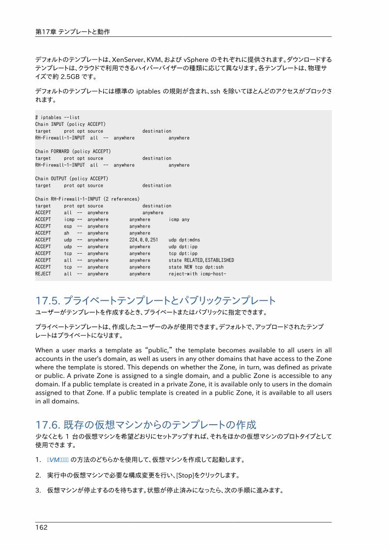
第17章 テンプレートと動作
162
デフォルトのテンプレートは、XenServer、KVM、および vSphere のそれぞれに提供されます。ダウンロードするテンプレートは、クラウドで利用できるハイパーバイザーの種類に応じて異なります。各テンプレートは、物理サイズで約 2.5GB です。
デフォルトのテンプレートには標準の iptables の規則が含まれ、ssh を除いてほとんどのアクセスがブロックされます。
# iptables --listChain INPUT (policy ACCEPT)target prot opt source destinationRH-Firewall-1-INPUT all -- anywhere anywhere
Chain FORWARD (policy ACCEPT)target prot opt source destinationRH-Firewall-1-INPUT all -- anywhere anywhere
Chain OUTPUT (policy ACCEPT)target prot opt source destination
Chain RH-Firewall-1-INPUT (2 references)target prot opt source destinationACCEPT all -- anywhere anywhereACCEPT icmp -- anywhere anywhere icmp anyACCEPT esp -- anywhere anywhereACCEPT ah -- anywhere anywhereACCEPT udp -- anywhere 224.0.0.251 udp dpt:mdnsACCEPT udp -- anywhere anywhere udp dpt:ippACCEPT tcp -- anywhere anywhere tcp dpt:ippACCEPT all -- anywhere anywhere state RELATED,ESTABLISHEDACCEPT tcp -- anywhere anywhere state NEW tcp dpt:sshREJECT all -- anywhere anywhere reject-with icmp-host-
17.5. プライベートテンプレートとパブリックテンプレートユーザーがテンプレートを作成するとき、プライベートまたはパブリックに指定できます。
プライベートテンプレートは、作成したユーザーのみが使用できます。デフォルトで、アップロードされたテンプレートはプライベートになります。
When a user marks a template as “public,” the template becomes available to all users in allaccounts in the user's domain, as well as users in any other domains that have access to the Zonewhere the template is stored. This depends on whether the Zone, in turn, was defined as privateor public. A private Zone is assigned to a single domain, and a public Zone is accessible to anydomain. If a public template is created in a private Zone, it is available only to users in the domainassigned to that Zone. If a public template is created in a public Zone, it is available to all usersin all domains.
17.6. 既存の仮想マシンからのテンプレートの作成少なくとも 1 台の仮想マシンを希望どおりにセットアップすれば、それをほかの仮想マシンのプロトタイプとして使用できま す。
1. �VM���� の方法のどちらかを使用して、仮想マシンを作成して起動します。
2. 実行中の仮想マシンで必要な構成変更を行い、[Stop]をクリックします。
3. 仮想マシンが停止するのを待ちます。状態が停止済みになったら、次の手順に進みます。
スナップショットからのテンプレートの作成
163
4. [Create Template]をクリックして、次の情報を入力します。
• Name および Display Text : これらはユーザーインターフェイスに表示されるため、わかりやすい言葉を選択しま す。
• OS Type : これは、CloudStack プラットフォームとハイパーバイザーで特定の処理を実行したり、想定に基づい てゲストのパフォーマンスを向上したりするのに役立ちます。次のいずれかのオプションを選択します。
• 停止している仮想マシンのオペレーティングシステムが一覧にある場合は、それを選択します。
• 停止している仮想マシンのオペレーティングシステムの種類が一覧にない場合は、[Other]を選択します。
• PV モードでこのテンプレートから起動する場合は、[Other PV(32-bit)]または[Other PV(64-bit)]を選択します。この選択肢は、XenServer でのみ使用できます。
注記注:通常は、イメージのオペレーティングシステムより古いバージョンを選択しないでください。たとえば、\nCentOS 6.2 イメージをサポートするために CentOS 5.4 を選択すると、通常は動作しません。このような場合は、 [Other]を選択する必要があります。
• Public : この CloudStack 環境のすべてのユーザーがこのテンプレートにアクセスできるようにするには、このチェックボックスをオンにします。テンプレートが [Community Templates] の一覧に表示されます。��������������������������を参照してください。
• Password Enabled: テンプレートに CloudStack プラットフォームのパスワード変更スクリプトがインストールされている場合は、このチェックボックスをオンにします。詳細は ���������������������� を参照してください。
5. [Add]をクリックします。
テンプレートの作成プロセスが完了すると、新しいテンプレートが[Templates]セクションに表示されます。このテンプレート\nは、新しい仮想マシンを作成するときに使用できます。
17.7. スナップショットからのテンプレートの作成[Create Template]メニュー項目を使用するために仮想マシンを停止したくない場合は(����������������������を参照)、CloudStack ユーザーインターフェイスを使用して、スナップショットからテンプレートを直接作成できます。
17.8. テンプレートのアップロード
vSphere テンプレートと ISOvSphere Client を使用して作成したテンプレートをアップロードする場合は、OVA ファイルにISO が含まれないことを確認してください。ISO が含まれていると、テンプレートから仮想マシンを展開できません。
第17章 テンプレートと動作
164
テンプレートは、URL に基づいてアップロードされます。サポートされるアクセスプロトコルは HTTP です。テンプレートは、 大きなファイルである場合がよくあります。オプションとして gzip 形式で圧縮し、アップロード時間を削減することができま す。
テンプレートをアップロードするには
1. 左側のナビゲーションバーで[Templates]をクリックします。
2. Click Register Template.
3. 次の情報を指定します。
• Name and Description. These will be shown in the UI, so choose something descriptive.
• URL. The Management Server will download the file from the specified URL, such as http://my.web.server/filename.vhd.gz.
• Zone. Choose the zone where you want the template to be available, or All Zones to makeit available throughout CloudStack.
• OS Type: This helps CloudStack and the hypervisor perform certain operations and makeassumptions that improve the performance of the guest. Select one of the following:
• 停止している仮想マシンのオペレーティングシステムが一覧にある場合は、それを選択します。
• 停止している仮想マシンのオペレーティングシステムの種類が一覧にない場合は、[Other]を選択します。
注記通常は、イメージのオペレーティングシステムより古いバージョンを選択しないでください。たとえば、\nCentOS 6.2 イメージをサポートするために CentOS 5.4 を選択すると、通常は動作しません。このような場合は、 [Other]を選択する必要があります。
• Hypervisor: The supported hypervisors are listed. Select the desired one.
• Format : VHD や OVA など、テンプレートのアップロードファイルの形式です。
• Password Enabled : テンプレートに CloudStackのパスワード変更スクリプトがインストールされている場合は、このチェックボックスをオンにします。「テンプレートへのパスワード管理機能の追加」を参照してください。
• Extractable : テンプレートを抽出可能にする場合、このチェックボックスをオンにします。エンドユーザーはテンプレートの全てのイメージをダウンロード可能になります。
• Public : この CloudStack 環境のすべてのユーザーがこのテンプレートにアクセスできるようにするには、このチェックボックスをオンにします。テンプレートが [Community Templates] の一覧に表示されます。��������������������������を参照してください。
• Featured : ユーザーがテンプレートを選択するときに「おすすめのテンプレート」としてこのテンプレートを目立た せるには、このチェックボックスをオンにします。テンプレートが[Featured Templates]の一覧に表示されます。 テンプレートをおすすめに設定できるのは管理者だけです。
テンプレートのエクスポート
165
17.9. テンプレートのエクスポートエンドユーザーと管理者はテンプレートを CloudStack からエクスポートすることができます。ユーザーインターフェイスでテンプレートに移動して、操作メニューの[Download Template]をクリックします。
17.10. Windows テンプレートの作成Windows テンプレートは、複数のコンピューターにプロビジョニングする前に、Sysprep を使用して準備する必要があります。 Sysprep を使用すると、汎用の Windows テンプレートを作成して SID の競合を回避することができます。
注記(XenServer) Windows 仮想マシンを XenServer 上で動作させるにはテンプレートとして提供するか仮想マシンの作成後に追加する PV ドライバーが必要となります。管理サーバーでの追加ボリュームやISOイメージのマウント、ライブマイグレーション、グレースフルシャットダウンといった機能を利用するには PV ドライバーは必須となります。
手順の概要は、次のとおりです。
1. Windows ISO をアップロードします。
詳しくは、�ISO ����を参照してください。
2. この ISO を使用して、仮想マシンインスタンスを作成します。
詳しくは、�VM����を参照してく ださい。
3. Windows Server のバージョンに応じて、次の「Windows Server 2008 R2 の Sysprep」または「Windows Server 2003 R2 の Sysprep」の手順に従います。
4. 準備の手順が完了しました。これで、「Windows テンプレートの作成」で説明するように、テンプレートを実際に作成できます。
17.10.1. Windows Server 2008 R2 の SysprepWindows Server 2008 R2 では、Windows システムイメージマネージャーを実行してカスタムの sysprep応答 XML ファイルを作成します。Windows システムイメージマネージャーは、Windows AIK(AutomatedInstallation Kit:自動インストールキット) の一部としてインストールされます。Windows AIK は、MicrosoftDownload Center1 からダウンロードできます。
Windows Server 2008 R2 で sysprep を実行するには、次の手順に従います。
注記ここで概要を示す手順は、Charity Shelbourne による優れたガイドに由来するものであり、元は次の URL で公開されてい ます。 Windows Server 2008 Sysprep Mini-Setup.2
1. Windows AIK をダウンロードしてインストールします。
1 http://www.microsoft.com/en-us/download/details.aspx?id=9085
第17章 テンプレートと動作
166
注記注:Windows AIK は、今作成した Windows Server 2008 R2 仮想マシンにはインストールしないでください。Windows AIK は、作成するテンプレートに含めないでください。sysprep 応答ファイルの作成のみに使用します。
2. Windows Server 2008 R2 のインストール DVD の\sources ディレクトリにあるinstall.wim ファイルをハードディスクにコピーします。これは非常に大きいファイルであり、コピーに長い時間がかかる場合があります。Windows AIK を使用するには、WIM ファイルを書き込み可能にする必要があります。
3. Windows AIK の一部である Windows システムイメージマネージャーを起動します。
4. [Windows イメージ]ペインで[Windows イメージまたはカタログファイルを指定してください]を右クリックして、今コピーした install.wim ファイルをロードします。
5. Windows 2008 R2 Edition を選択します。
カタログファイルを開くことができないと警告するダイアログボックスが表示されることがあります。新しいカタログファイルを作成するには、[はい]をクリックします。
6. [応答ファイル]ペインで、右クリックして新しい応答ファイルを作成します。
7. 次の手順に従って、Windows システムイメージマネージャーから応答ファイルを作成します。
a. 自動化する必要がある最初のページは、言語および国や地域を選択するページです。これを自動化するには、 [Windows イメージ]ペインで[Components]を展開し、右クリックして[Microsoft-Windows-International-Core] 設定を[7 oobeSystem]に追加します。[応答ファイル]ペインで、使用する言語と国または地域に合わせて、 [InputLocale]、[SystemLocale]、[UILanguage]、および[UserLocale]を適切に構成します。これらの設定でわ からない点がある場合は、特定の設定を右クリックして[ヘルプ]をクリックします。すると、構成しようとしている設定の例を含む詳細情報が記載された、適切な CHMヘルプファイルが開きます。
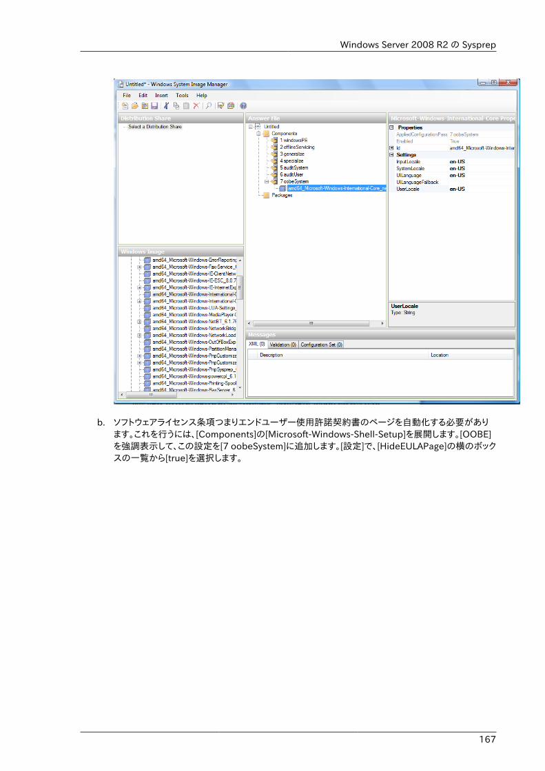
Windows Server 2008 R2 の Sysprep
167
b. ソフトウェアライセンス条項つまりエンドユーザー使用許諾契約書のページを自動化する必要があります。これを行うには、[Components]の[Microsoft-Windows-Shell-Setup]を展開します。[OOBE]を強調表示して、この設定を[7 oobeSystem]に追加します。[設定]で、[HideEULAPage]の横のボックスの一覧から[true]を選択します。
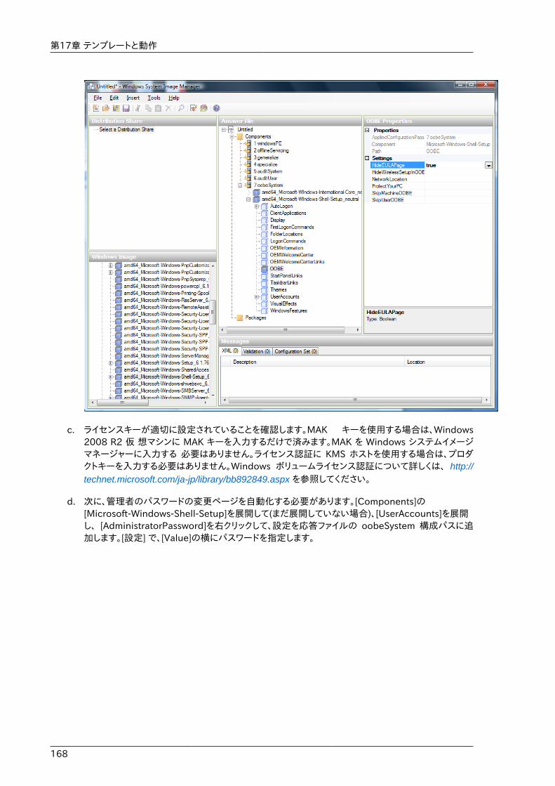
第17章 テンプレートと動作
168
c. ライセンスキーが適切に設定されていることを確認します。MAK キーを使用する場合は、Windows2008 R2 仮 想マシンに MAK キーを入力するだけで済みます。MAK を Windows システムイメージマネージャーに入力する 必要はありません。ライセンス認証に KMS ホストを使用する場合は、プロダクトキーを入力する必要はありません。Windows ボリュームライセンス認証について詳しくは、 http://technet.microsoft.com/ja-jp/library/bb892849.aspx を参照してください。
d. 次に、管理者のパスワードの変更ページを自動化する必要があります。[Components]の[Microsoft-Windows-Shell-Setup]を展開して(まだ展開していない場合)、[UserAccounts]を展開し、 [AdministratorPassword]を右クリックして、設定を応答ファイルの oobeSystem 構成パスに追加します。[設定] で、[Value]の横にパスワードを指定します。
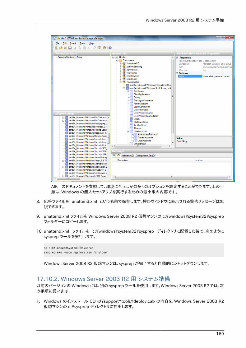
Windows Server 2003 R2 用 システム準備
169
AIK のドキュメントを参照して、環境に合うほかの多くのオプションを設定することができます。上の手順は、Windows の無人セットアップを実行するための最小限の内容です。
8. 応答ファイルを unattend.xml という名前で保存します。検証ウィンドウに表示される警告メッセージは無視できます。
9. unattend.xml ファイルを Windows Server 2008 R2 仮想マシンの c:\windows\system32\sysprepフォルダーにコピーします。
10. unattend.xml ファイルを c:\windows\system32\sysprep ディレクトリに配置した後で、次のようにsysprep ツールを実行します。
cd c:\Windows\System32\sysprepsysprep.exe /oobe /generalize /shutdown
Windows Server 2008 R2 仮想マシンは、sysprep が完了すると自動的にシャットダウンします。
17.10.2. Windows Server 2003 R2 用 システム準備以前のバージョンの Windows には、別の sysprep ツールを使用します。Windows Server 2003 R2 では、次の手順に従いま す。
1. Windows のインストール CD の\support\tools\deploy.cab の内容を、Windows Server 2003 R2仮想マシンの c:\sysprep ディレクトリに抽出します。
第17章 テンプレートと動作
170
2. c:¥sysprep¥setupmgr.exe を実行して、sysprep.inf ファイルを作成します。
a. [新しい応答ファイルを作成する]をクリックして、新しい応答ファイルを作成します。
b. [セットアップの種類]ページで、[Sysprep セットアップ]をクリックします。
c. 適切なオペレーティングシステムのバージョンとエディションを選択します。
d. [使用許諾契約書]ページで、[はい、インストールを完全に自動化します]をクリックします。
e. 名前と組織を入力します。
f. ディスプレイの設定はデフォルトのままにします。
g. 適切なタイムゾーンを設定します。
h. プロダクトキーを入力します。
i. 環境に合ったライセンスモードを選択します。
j. [コンピュータ名を自動で生成する]をクリックします。
k. デフォルトの管理者パスワードを入力します。パスワードのリセット機能を有効にした場合は、ユーザーは実際にはこのパスワードを使用しません。このパスワードは、ゲストの起動後にインスタンスマネージャーによってリセットされます。
l. [ネットワークコンポーネント]ページの設定は、[標準的な設定]のままにします。
m. [ワークグループ]をクリックして設定します。
n. [テレフォニー]ページの設定はデフォルトのままにします。
o. 適切な地域設定を選択します。
p. 適切な言語設定を選択します。
q. プリンターをインストールしないでください。
r. 最初のログオン時に実行するコマンドは指定しないでください。
s. ID 文字列を指定する必要はありません。
t. 応答ファイルを c:\sysprep\sysprep.inf という名前で保存します。
3. 次のコマンドを実行して、イメージに sysprep を実行します。
c:\sysprep\sysprep.exe -reseal -mini -activated
この手順の後で、マシンは自動的にシャットダウンします。
17.11. AMI のインポート次の手順では、XenServer ハイパーバイザーを使用する場合に、AMI(Amazon Machine Image)をCloudStackにインポートする方法を説明します。
AMI のインポート
171
AMI ファイルがあり、そのファイルが CentOS_6.2_x64 という名前である ことを前提としています。さらに、CentOS ホストで作業することを前提と しています。AMI が Fedora イメージである場合は、まず Fedora ホストで作業する必要があります。
注:イメージファイルを Centos/Fedora ホストでカスタマイズした後に VHD に変換する場合は、ファイルベースのストレージリポジトリ(ローカ ル ext3 または NFS のどちらか)を持つ XenServer ホストが必要です。
注記コマンドをコピーして実行するときは、単一の行として貼り付けたことを確認してください。一部のドキュメントビューアーでは、コピーしたテキストに不要な改行が含まれる可能性があります。
AMI をインポートするには
1. イメージファイルでループバックをセットアップします。
# mkdir -p /mnt/loop/centos62# mount -o loop CentOS_6.2_x64 /mnt/loop/centos54
2. kernel-xen パッケージをイメージにインストールします。これにより、PV カーネルおよび RAM ディスクがイメージにダウンロードされます。
# yum -c /mnt/loop/centos54/etc/yum.conf --installroot=/mnt/loop/centos62/ -y install kernel-xen
3. grub エントリを/boot/grub/grub.conf に作成します。
# mkdir -p /mnt/loop/centos62/boot/grub# touch /mnt/loop/centos62/boot/grub/grub.conf# echo "" > /mnt/loop/centos62/boot/grub/grub.conf
4. イメージにインストールされた PV カーネルの名前を確認します。
# cd /mnt/loop/centos62# ls lib/modules/2.6.16.33-xenU 2.6.16-xenU 2.6.18-164.15.1.el5xen 2.6.18-164.6.1.el5.centos.plus 2.6.18-xenU-ec2-v1.0 2.6.21.7-2.fc8xen 2.6.31-302-ec2# ls boot/initrd*boot/initrd-2.6.18-164.6.1.el5.centos.plus.img boot/initrd-2.6.18-164.15.1.el5xen.img# ls boot/vmlinuz*boot/vmlinuz-2.6.18-164.15.1.el5xen boot/vmlinuz-2.6.18-164.6.1.el5.centos.plus boot/vmlinuz-2.6.18-xenU-ec2-v1.0 boot/vmlinuz-2.6.21-2952.fc8xen
Xen kernels/ramdisk always end with "xen". For the kernel version you choose, there has to bean entry for that version under lib/modules, there has to be an initrd and vmlinuz correspondingto that. Above, the only kernel that satisfies this condition is 2.6.18-164.15.1.el5xen.
5. 調べた結果に基づいて、grub.conf ファイルにエントリを作成します。エントリの例を次に示します。
default=0timeout=5hiddenmenutitle CentOS (2.6.18-164.15.1.el5xen)
第17章 テンプレートと動作
172
root (hd0,0) kernel /boot/vmlinuz-2.6.18-164.15.1.el5xen ro root=/dev/xvda initrd /boot/initrd-2.6.18-164.15.1.el5xen.img
6. etc/fstab を編集します。「sda1」を「xvda」に、「sdb」を「xvdb」に変更します。
# cat etc/fstab/dev/xvda / ext3 defaults 1 1/dev/xvdb /mnt ext3 defaults 0 0none /dev/pts devpts gid=5,mode=620 0 0none /proc proc defaults 0 0none /sys sysfs defaults 0 0
7. コンソール経由でのログオンを有効にします。XenServer システムのデフォルトのコンソールデバイスはxvc0 です。 etc/inittab と etc/securetty に、それぞれ次の行があることを確認します。
# grep xvc0 etc/inittab co:2345:respawn:/sbin/agetty xvc0 9600 vt100-nav# grep xvc0 etc/securetty xvc0
8. RAM ディスクが PV ディスクと PV ネットワークをサポートしていることを確認します。上の例で確認したカーネルバー ジョンに合わせて、これをカスタマイズします。
# chroot /mnt/loop/centos54# cd /boot/# mv initrd-2.6.18-164.15.1.el5xen.img initrd-2.6.18-164.15.1.el5xen.img.bak# mkinitrd -f /boot/initrd-2.6.18-164.15.1.el5xen.img --with=xennet --preload=xenblk --omit-scsi-modules 2.6.18-164.15.1.el5xen
9. パスワードを変更します。
# passwdChanging password for user root.New UNIX password: Retype new UNIX password: passwd: all authentication tokens updated successfully.
10. chroot を終了します。
# exit
11. etc/ssh/sshd_config の、パスワードを使用して ssh ログオンを許可する行を確認します。
# egrep "PermitRootLogin|PasswordAuthentication" /mnt/loop/centos54/etc/ssh/sshd_config PermitRootLogin yesPasswordAuthentication yes
12. テンプレートのパスワードを CloudStack ユーザーインターフェイスまたは API からリセットできるようにする必要がある場合は、この時点でパスワード変更スクリプトをイメージにインストールします。����������������������を参照してください。
13. ループバックマウントを解除して削除します。
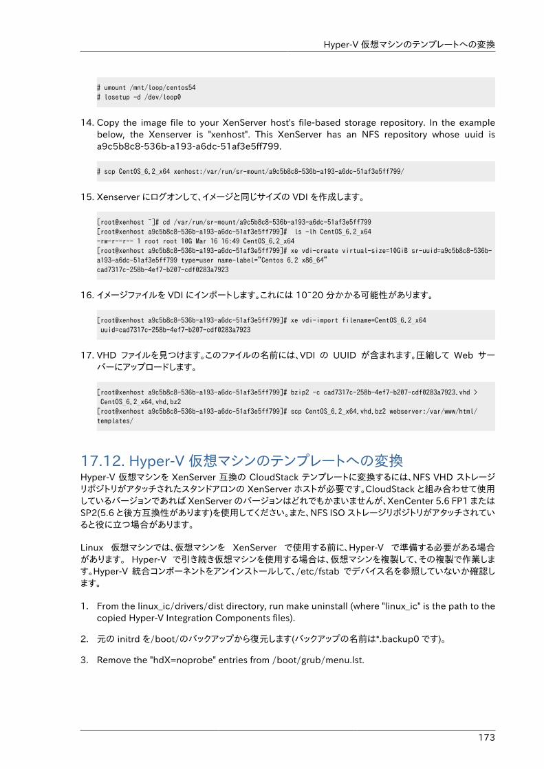
Hyper-V 仮想マシンのテンプレートへの変換
173
# umount /mnt/loop/centos54# losetup -d /dev/loop0
14. Copy the image file to your XenServer host's file-based storage repository. In the examplebelow, the Xenserver is "xenhost". This XenServer has an NFS repository whose uuid isa9c5b8c8-536b-a193-a6dc-51af3e5ff799.
# scp CentOS_6.2_x64 xenhost:/var/run/sr-mount/a9c5b8c8-536b-a193-a6dc-51af3e5ff799/
15. Xenserver にログオンして、イメージと同じサイズの VDI を作成します。
[root@xenhost ~]# cd /var/run/sr-mount/a9c5b8c8-536b-a193-a6dc-51af3e5ff799[root@xenhost a9c5b8c8-536b-a193-a6dc-51af3e5ff799]# ls -lh CentOS_6.2_x64-rw-r--r-- 1 root root 10G Mar 16 16:49 CentOS_6.2_x64[root@xenhost a9c5b8c8-536b-a193-a6dc-51af3e5ff799]# xe vdi-create virtual-size=10GiB sr-uuid=a9c5b8c8-536b-a193-a6dc-51af3e5ff799 type=user name-label="Centos 6.2 x86_64"cad7317c-258b-4ef7-b207-cdf0283a7923
16. イメージファイルを VDI にインポートします。これには 10~20 分かかる可能性があります。
[root@xenhost a9c5b8c8-536b-a193-a6dc-51af3e5ff799]# xe vdi-import filename=CentOS_6.2_x64 uuid=cad7317c-258b-4ef7-b207-cdf0283a7923
17. VHD ファイルを見つけます。このファイルの名前には、VDI の UUID が含まれます。圧縮して Web サーバーにアップロードします。
[root@xenhost a9c5b8c8-536b-a193-a6dc-51af3e5ff799]# bzip2 -c cad7317c-258b-4ef7-b207-cdf0283a7923.vhd > CentOS_6.2_x64.vhd.bz2[root@xenhost a9c5b8c8-536b-a193-a6dc-51af3e5ff799]# scp CentOS_6.2_x64.vhd.bz2 webserver:/var/www/html/templates/
17.12. Hyper-V 仮想マシンのテンプレートへの変換Hyper-V 仮想マシンを XenServer 互換の CloudStack テンプレートに変換するには、NFS VHD ストレージリポジトリがアタッチされたスタンドアロンの XenServer ホストが必要です。CloudStack と組み合わせて使用しているバージョンであれば XenServer のバージョンはどれでもかまいませんが、XenCenter 5.6 FP1 またはSP2(5.6 と後方互換性があります)を使用してください。また、NFS ISO ストレージリポジトリがアタッチされていると役に立つ場合があります。
Linux 仮想マシンでは、仮想マシンを XenServer で使用する前に、Hyper-V で準備する必要がある場合があります。 Hyper-V で引き続き仮想マシンを使用する場合は、仮想マシンを複製して、その複製で作業します。Hyper-V 統合コンポーネントをアンインストールして、/etc/fstab でデバイス名を参照していないか確認します。
1. From the linux_ic/drivers/dist directory, run make uninstall (where "linux_ic" is the path to thecopied Hyper-V Integration Components files).
2. 元の initrd を/boot/のバックアップから復元します(バックアップの名前は*.backup0 です)。
3. Remove the "hdX=noprobe" entries from /boot/grub/menu.lst.
第17章 テンプレートと動作
174
4. デバイス名でマウントされているパーティションがないか/etc/fstab を確認します。そのようなエントリがある場合は、 LABEL または UUID でマウントするよう変更します。この情報を取得するには blkid コマンドを実行します。
次に、仮想マシンが Hyper-V で動作していないことを確認してから、VHD を XenServer に取り込みます。これを行うには、 2 つの方法があります。
オプション 1
1. Import the VHD using XenCenter. In XenCenter, go to Tools>Virtual Appliance Tools>DiskImage Import.
2. [VHD]を選択し、[次へ]をクリックします。
3. Name the VM, choose the NFS VHD SR under Storage, enable "Run Operating System Fixups"and choose the NFS ISO SR.
4. [次へ]をクリックし、[完了]をクリックします。これで、仮想マシンが作成されます。
オプション 2
1. XenConvert を実行して、[変換元]ボックスの一覧で[VHD]を選択し、[変換先]ボックスの一覧で[XenServer]を選択します。[次へ]をクリックします。
2. [VHD]を選択し、[次へ]をクリックします。
3. XenServer ホストの情報を入力し、[次へ]をクリックします。
4. 仮想マシンに名前を付け、[次へ]をクリックし、[変換]をクリックします。これで、仮想マシンが作成されます。
Hyper-V VHD から仮想マシンを作成したら、次の手順に従って、その仮想マシンを準備します。
1. 仮想マシンを起動して、Hyper-V 統合サービスをアンインストールし、再起動します。
2. XenServer Tools をインストールし、再起動します。
3. 必要に応じて仮想マシンを準備します。たとえば、Windows 仮想マシンで sysprep を実行します。詳細は�Windows ���������� を参照してください。
上のオプションのどちらでも、HVM モードの仮想マシンが作成されます。Windows 仮想マシンの場合は問題はありません が、Linux 仮想マシンは適切に動作しない場合があります。Linux 仮想マシンを PV モードに変換するには、追加の手順を 実行する必要があり、その手順はディストリビューションごとに異なります。
1. 仮想マシンをシャットダウンして、VHD を NFS ストレージから Web サーバーにコピーします。たとえば、NFS 共有を Web サーバーにマウントしてコピーするか、XenServer ホストから sftp または scp を使用して、Web サーバーにアップロードします。
2. CloudStack で次の値を使用して、新しいテンプレートを作成します。
• URL : VHD の URL を指定します。
• OS Type : 適切なオペレーティングシステムを使用します。PV モードの CentOS の場合は、[OtherPV(32-bit)] または[Other PV(64-bit)]を選択します。この選択肢は、XenServer でのみ使用できます。
• Hypervisor : [XenServer]を選択します。
• Format : [VHD]を選択します。
テンプレートへのパスワード管理機能の追加
175
テンプレートが作成され、そのテンプレートからインスタンスを作成できます。
17.13. テンプレートへのパスワード管理機能の追加CloudStack は、パスワードのリセット機能をオプションで提供します。ユーザーは CloudStack ユーザーインターフェイスで一時的な管理者パスワードまたはルートパスワードを設定したり、既存の管理者パスワードまたはルートパスワードをリセットしたりできます。
パスワードのリセット機能を有効にするには、追加のスクリプトをダウンロードしてテンプレートに適用する必要があります。 テンプレートを後で CloudStack にアップロードする場合は、このテンプレートで管理者/ルートパスワードのリセット機能を有効にするかどうかを指定できます。
パスワード管理機能により、インスタンスの起動時にアカウントのパスワードが常にリセットされます。スクリプトにより仮想ルーターに HTTP 呼び出しが行われ、設定する必要があるアカウントのパスワードが取得されます。仮想ルーターにアクセスできる限り、ゲストは使用する必要があるアカウントのパスワードにアクセスできます。ユーザーがパスワードのリセットを要求すると、管理サーバーにより新しいパスワードが生成され、そのアカウントの仮想ルーターに送信されます。このため、パスワードの変更を有効にするには、インスタンスの再起動が必要です。
インスタンスの起動中にスクリプトが仮想ルーターと通信できない場合は、パスワードは設定されず、通常どおり起動が続行されます。
17.13.1. Linux オペレーティングシステムのインストール次の手順に従って、Linux オペレーティングシステムのインストールを開始します。
1. スクリプトファイルの cloud-set-guest-password をダウンロードします。
• Linux: http://cloudstack.org/dl/cloud-set-guest-password
• Windows: http://sourceforge.net/projects/cloudstack/files/Password%20Management%20Scripts/CloudInstanceManager.msi/download
2. このファイルを/etc/init.d にコピーします。
一部の Linux ディストリビューションでは、このファイルを/etc/rc.d/init.d にコピーします。
3. 次のコマンドを実行して、スクリプトを実行可能にします。
chmod +x /etc/init.d/cloud-set-guest-password
4. Linux ディストリビューションに応じて、適切な手順を続行します。
Fedora、CentOS/RHEL、および Debian:
chkconfig --add cloud-set-guest-password
17.13.2. Window オペレーティングシステムのインストールインストーラーの CloudInstanceManager.msi を Download page3 からダウンロードして、新しく作成したWindows 仮想マシンで実行します。
3 http://cloudstack.org/download.html

第17章 テンプレートと動作
176
17.14. テンプレートの削除テンプレートは削除することができます。通例、テンプレートが複数のゾーンにまたがって存在する場合は、削除のために選択されたコピーのみが削除されます。ほかのゾーンの同じテンプレートは削除されません。CloudStack で提供する CentOS テンプ レートは、これに当てはまりません。CloudStack で提供するCentOS テンプレートを削除すると、すべてのゾーンから削除されます。
テンプレートを削除しても、そのテンプレートからインスタンス化された仮想マシンは引き続き動作します。ただし、削除されたテンプレートに基づいて新しい仮想マシンを作成することはできません。
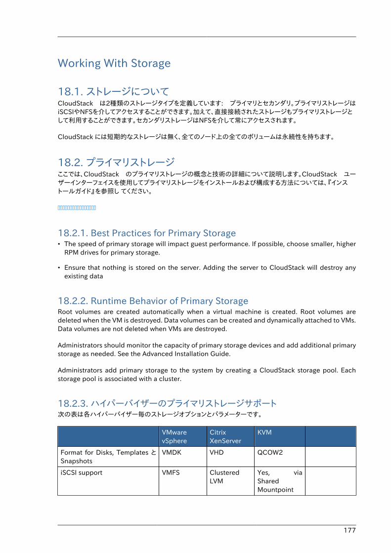
177
Working With Storage
18.1. ストレージについてCloudStack は2種類のストレージタイプを定義しています: プライマリとセカンダリ。プライマリストレージはiSCSIやNFSを介してアクセスすることができます。加えて、直接接続されたストレージもプライマリストレージとして利用することができます。セカンダリストレージはNFSを介して常にアクセスされます。
CloudStack には短期的なストレージは無く、全てのノード上の全てのボリュームは永続性を持ちます。
18.2. プライマリストレージここでは、CloudStack のプライマリストレージの概念と技術の詳細について説明します。CloudStack ユーザーインターフェイスを使用してプライマリストレージをインストールおよび構成する方法については、『インストールガイド』を参照し てください。
����������������
18.2.1. Best Practices for Primary Storage• The speed of primary storage will impact guest performance. If possible, choose smaller, higher
RPM drives for primary storage.
• Ensure that nothing is stored on the server. Adding the server to CloudStack will destroy anyexisting data
18.2.2. Runtime Behavior of Primary StorageRoot volumes are created automatically when a virtual machine is created. Root volumes aredeleted when the VM is destroyed. Data volumes can be created and dynamically attached to VMs.Data volumes are not deleted when VMs are destroyed.
Administrators should monitor the capacity of primary storage devices and add additional primarystorage as needed. See the Advanced Installation Guide.
Administrators add primary storage to the system by creating a CloudStack storage pool. Eachstorage pool is associated with a cluster.
18.2.3. ハイパーバイザーのプライマリストレージサポート次の表は各ハイパーバイザー毎のストレージオプションとパラメーターです。
VMwarevSphere
CitrixXenServer
KVM
Format for Disks, Templates とSnapshots
VMDK VHD QCOW2
iSCSI support VMFS ClusteredLVM
Yes, viaSharedMountpoint
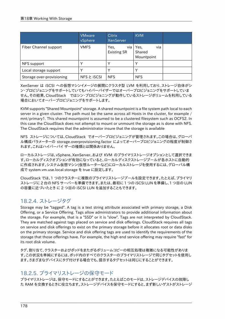
第18章 Working With Storage
178
VMwarevSphere
CitrixXenServer
KVM
Fiber Channel support VMFS Yes, viaExisting SR
Yes, viaSharedMountpoint
NFS support Y Y Y
Local storage support Y Y Y
Storage over-provisioning NFS と iSCSI NFS NFS
XenServer は iSCSI への仮想マシンイメージの展開にクラスタ型 LVM を利用しており、ストレージ自体がシン・プロビジョニングをサポートしていてもハイパーバイザーではオーバープロビジョニングをサポートしていません。その結果、CloudStack ではシン・プロビジョニングが動作しているストレージボリュームを利用している場合においてオーバープロビジョニングをサポートします。
KVM supports "Shared Mountpoint" storage. A shared mountpoint is a file system path local to eachserver in a given cluster. The path must be the same across all Hosts in the cluster, for example /mnt/primary1. This shared mountpoint is assumed to be a clustered filesystem such as OCFS2. Inthis case the CloudStack does not attempt to mount or unmount the storage as is done with NFS.The CloudStack requires that the administrator insure that the storage is available
NFS ストレージについては、CloudStack でオーバープロビジョニングが管理されます。この場合は、グローバル構成パラメーターの storage.overprovisioning.factor によってオーバープロビジョニングの程度が制御されます。これはハイパーバイ ザーの種類とは関係ありません。
ローカルストレージは、vSphere、XenServer、および KVM のプライマリストレージオプションとして選択できます。ローカルディスクオプションが有効になっていると、ローカルディスクストレージプールが各ホストに自動的に作成されます。システム仮想マシン(仮想ルーターなど)にローカルストレージを使用するには、グローバル構成で system.vm.use.local.storage を true に設定します。
CloudStack では、1 つのクラスターに複数のプライマリストレージプールを設定できます。たとえば、プライマリストレージに 2 台の NFS サーバーを準備できます。または、最初に 1 つの iSCSI LUN を準備し、1 つ目の LUNの容量に近づいたとき に 2 つ目の iSCSI LUN を追加することもできます。
18.2.4. ストレージタグStorage may be "tagged". A tag is a text string attribute associated with primary storage, a DiskOffering, or a Service Offering. Tags allow administrators to provide additional information aboutthe storage. For example, that is a "SSD" or it is "slow". Tags are not interpreted by CloudStack.They are matched against tags placed on service and disk offerings. CloudStack requires all tagson service and disk offerings to exist on the primary storage before it allocates root or data diskson the primary storage. Service and disk offering tags are used to identify the requirements of thestorage that those offerings have. For example, the high end service offering may require "fast" forits root disk volume.
タグ、割り当て、クラスターおよびポッドをまたがるボリュームコピーの相互処理は複雑になる可能性があります。この状況を単純にするには、ポッド内のすべてのクラスターのプライマリストレージで同じタグセットを使用します。さまざまなデバイスにタグ付けする場合でも、提示するタグセットは同じにすることができます。
18.2.5. プライマリストレージの保守モードプライマリストレージは、保守モードにすることができます。たとえばこのモードは、ストレージデバイスの故障した RAM を交換するときに役立ちます。ストレージデバイスを保守モードにすると、まず新しいゲストがストレージ
セカンダリストレージ
179
デバイスにプロビジョニングされなくなります。続いて、そのストレージデバイスにボリュームを持つすべてのゲストが停止されます。そのようなゲストがすべて停止されると、ストレージデバイスは保守モードに入ったものとしてシャットダウンできるようになります。 ストレージデバイスが再びオンラインになったときに、デバイスの保守モードをキャンセルすることができます。CloudStack によってデバイスがオンラインに戻され、保守モードに入ったときに実行していたすべてのゲストの起動が試行されます。
18.3. セカンダリストレージここでは、CloudStack のセカンダリストレージの概念と技術の詳細について説明します。CloudStack ユーザーインターフェイスを使用してセカンダリストレージをインストールおよび構成する方法については、『インストールガイド上級編』を参照してください。
����������������
18.4. Working With Volumesボリュームは仮想マシンに対するストレージを提供し、ルートディスクや追加のデータディスクとして仮想マシンに提供されます。CloudStack は仮想マシンへの追加ボリュームをサポートしています。
Volumes are created for a specific hypervisor type. A volume that has been attached to guest usingone hypervisor type (e.g, XenServer) may not be attached to a guest that is using another hypervisortype, for example:vSphere, KVM. This is because the different hypervisors use different disk imageformats.
CloudStack defines a volume as a unit of storage available to a guest VM. Volumes are either rootdisks or data disks. The root disk has "/" in the file system and is usually the boot device. Data disksprovide for additional storage, for example: "/opt" or "D:". Every guest VM has a root disk, and VMscan also optionally have a data disk. End users can mount multiple data disks to guest VMs. Userschoose data disks from the disk offerings created by administrators. The user can create a templatefrom a volume as well; this is the standard procedure for private template creation. Volumes arehypervisor-specific: a volume from one hypervisor type may not be used on a guest of anotherhypervisor type.
注記CloudStack supports attaching up to 13 data disks to a VM on XenServer hypervisorversions 6.0 and above. For the VMs on other hypervisor types, the data disk limitis 6.
18.4.1. 新しいボリュームの作成ストレージ容量の上限まで、いつでもゲスト仮想マシンにデータディスクボリュームを追加できます。CloudStack 管理者とユーザーの両方が、仮想マシンインスタンスにボリュームを追加できます。新しいボリュームを作成するとエンティティとして CloudStack に格納されますが、ボリュームをアタッチするまでは、実際のストレージリソースは物理ストレージデバイスに割り当てられません。この最適化により、最初のアタッチが行われるとき、ボリュームを使用するゲストに最も近い場所にボリュームが準備されます。
18.4.1.1. Using Local Storage for Data VolumesYou can create data volumes on local storage (supported with XenServer, KVM, and VMware). Thedata volume is placed on the same host as the VM instance that is attached to the data volume.
第18章 Working With Storage
180
These local data volumes can be attached to virtual machines, detached, re-attached, and deletedjust as with the other types of data volume.
Local storage is ideal for scenarios where persistence of data volumes and HA is not required. Someof the benefits include reduced disk I/O latency and cost reduction from using inexpensive localdisks.
In order for local volumes to be used, the feature must be enabled for the zone.
You can create a data disk offering for local storage. When a user creates a new VM, they can selectthis disk offering in order to cause the data disk volume to be placed in local storage.
You can not migrate a VM that has a volume in local storage to a different host, nor migrate thevolume itself away to a different host. If you want to put a host into maintenance mode, you mustfirst stop any VMs with local data volumes on that host.
18.4.1.2. To Create a New Volume1. ユーザーもしくは管理者として CloudStack ユーザーインターフェイスからログインします。
2. 左側のナビゲーションバーで[Storage]をクリックします。
3. [Select view]ボックスの一覧で[Volumes]を選択します。
4. 新しいボリュームを作成するには[Add Volume]をクリックして次の詳細情報を入力し、[OK]をクリックします。
• Name: 後で見つけられるように、ボリュームに一意の名前を付けます。
• Availability Zone: ストレージの場所です。ボリュームを使用する仮想マシンに近い場所にする必要があります。
• Disk Offering: ストレージの特性を選択します。
新しいボリュームがボリューム一覧に表示され、割り当て済みの状態になります。ボリュームデータはCloudStack に格納されましたが、実際には使用する準備はできていません。
5. ボリュームを使用するには、「ボリュームのアタッチ」に進みます。
18.4.2. Uploading an Existing Volume to a Virtual MachineExisting data can be made accessible to a virtual machine. This is called uploading a volume to theVM. For example, this is useful to upload data from a local file system and attach it to a VM. Rootadministrators, domain administrators, and end users can all upload existing volumes to VMs.
The upload is performed using HTTP. The uploaded volume is placed in the zone's secondarystorage
You cannot upload a volume if the preconfigured volume limit has already been reached. Thedefault limit for the cloud is set in the global configuration parameter max.account.volumes, butadministrators can also set per-domain limits that are different from the global default. See SettingUsage Limits
To upload a volume:
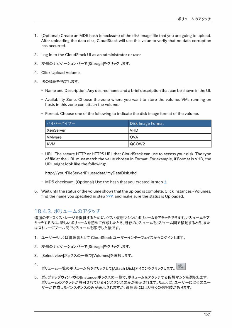
ボリュームのアタッチ
181
1. (Optional) Create an MD5 hash (checksum) of the disk image file that you are going to upload.After uploading the data disk, CloudStack will use this value to verify that no data corruptionhas occurred.
2. Log in to the CloudStack UI as an administrator or user
3. 左側のナビゲーションバーで[Storage]をクリックします。
4. Click Upload Volume.
5. 次の情報を指定します。
• Name and Description. Any desired name and a brief description that can be shown in the UI.
• Availability Zone. Choose the zone where you want to store the volume. VMs running onhosts in this zone can attach the volume.
• Format. Choose one of the following to indicate the disk image format of the volume.
ハイパーバイザー Disk Image Format
XenServer VHD
VMware OVA
KVM QCOW2
• URL. The secure HTTP or HTTPS URL that CloudStack can use to access your disk. The typeof file at the URL must match the value chosen in Format. For example, if Format is VHD, theURL might look like the following:
http://yourFileServerIP/userdata/myDataDisk.vhd
• MD5 checksum. (Optional) Use the hash that you created in step 1.
6. Wait until the status of the volume shows that the upload is complete. Click Instances - Volumes,find the name you specified in step ???, and make sure the status is Uploaded.
18.4.3. ボリュームのアタッチ追加のディスクストレージを提供するために、ゲスト仮想マシンにボリュームをアタッチできます。ボリュームをアタッチするのは、新しいボリュームを初めて作成したとき、既存のボリュームをボリューム間で移動するとき、またはストレージプール間でボリュームを移行した後です。
1. ユーザーもしくは管理者として CloudStack ユーザーインターフェイスからログインします。
2. 左側のナビゲーションバーで[Storage]をクリックします。
3. [Select view]ボックスの一覧で[Volumes]を選択します。
4.ボリューム一覧のボリューム名をクリックして[Attach Disk]アイコンをクリックします。
5. ポップアップウィンドウの[Instance]ボックスの一覧で、ボリュームをアタッチする仮想マシンを選択します。ボリュームのアタッチが許可されているインスタンスのみが表示されます。たとえば、ユーザーにはそのユーザーが作成したインスタンスのみが表示されますが、管理者にはより多くの選択肢があります。
第18章 Working With Storage
182
6. [Instances]、インスタンス名、[View Volumes]の順にクリックすると、ボリュームをアタッチ済みかどうかわかりま す。
18.4.4. Detaching and Moving Volumes
注記�この手順は、ストレージプール間でディスクボリュームを移動する手順とは異なります。「仮想マシンストレージの移行」を参照してください。
ボリュームは、ゲスト仮想マシンからデタッチして別のゲストにアタッチ できます。CloudStack 管理者とユーザーの両方が、仮想マシンからボリュームをデタッチしてほかの仮想マシンに移動することができます。
2 つの仮想マシンが異なるクラスターに存在しボリュームが大きい場合 は、新しい仮想マシンにボリュームを移動するのに数分かかる可能性があります。
1. ユーザーもしくは管理者として CloudStack UIからログインします。
2. 左側のナビゲーションバーで[Storage]をクリックし、[Select View]ボックスの一覧で[Volumes]を選択します。ボリュームのアタッチ先の仮想マシンがわかっている場合は、[Instances]、インスタンス名、[ViewVolumes]の順にクリックします。
3.Click the name of the volume you want to detach, then click the Detach Disk button.
4. To move the volume to another VM, follow the steps in ������������.
18.4.5. VM Storage MigrationSupported in XenServer, KVM, and VMware.
注記This procedure is different from moving disk volumes from one VM to another. SeeDetaching and Moving Volumes �Detaching and Moving Volumes�.
You can migrate a virtual machine’s root disk volume or any additional data disk volume from onestorage pool to another in the same zone.
You can use the storage migration feature to achieve some commonly desired administration goals,such as balancing the load on storage pools and increasing the reliability of virtual machines bymoving them away from any storage pool that is experiencing issues.
18.4.5.1. データディスクボリュームの新しいストレージプールへの移行1. ユーザーもしくは管理者として CloudStack UIからログインします。
2. 仮想マシンからデータディスクをデタッチします。「ボリュームのデタッチと移動」�Detaching and MovingVolumes�を参照してください(ただし、最後の「再アタッチ」の手順は飛ばして下さい。これは新しいストレージへの移行完了後に実施します)。
ボリュームのサイズ変更
183
3. CloudStack API コマンドの migrateVolume を呼び出して、ボリューム ID およびゾーン内の任意のストレージプール ID を渡します。
4. ボリュームの状態が移行中から準備完了になるのを待ちます。
5. 新しいストレージサーバーと同じクラスター内の、望ましい仮想マシンにボリュームをアタッチします。「ボリュームの\nアタッチ������������」を参照してください。
18.4.5.2. 仮想マシンルートボリュームの新しいストレージプールへの移行ルートディスクボリュームの移行時には、まず仮想マシンを停止して、ユーザーがアクセスできないようにする必要があります。移行が完了したら、仮想マシンを再起動できます。
1. CloudStack ユーザーインターフェイスに管理者としてログインします。
2. 仮想マシンからデータディスクをデタッチします。「ボリュームのデタッチと移動」�Detaching and MovingVolumes�を参照してください(ただし、最後の「再アタッチ」の手順は飛ばして下さい。これは新しいストレージへの移行完了後に実施します)。
3. 仮想マシンを停止します。
4. CloudStack API コマンドの migrateVirtualMachine を呼び出して、移行する仮想マシンの ID と、同じゾーン内の移行先のホストおよびストレージプールの ID を渡します。
5. 仮想マシンの状態が移行中から停止済みになるのを待ちます。
6. 仮想マシンを再起動します。
18.4.6. ボリュームのサイズ変更CloudStack provides the ability to resize data disks; CloudStack controls volume size by using diskofferings. This provides CloudStack administrators with the flexibility to choose how much spacethey want to make available to the end users. Volumes within the disk offerings with the samestorage tag can be resized. For example, if you only want to offer 10, 50, and 100 GB offerings,the allowed resize should stay within those limits. That implies if you define a 10 GB, a 50 GB anda 100 GB disk offerings, a user can upgrade from 10 GB to 50 GB, or 50 GB to 100 GB. If youcreate a custom-sized disk offering, then you have the option to resize the volume by specifyinga new, larger size.
Additionally, using the resizeVolume API, a data volume can be moved from a static disk offering toa custom disk offering with the size specified. This functionality allows those who might be billingby certain volume sizes or disk offerings to stick to that model, while providing the flexibility tomigrate to whatever custom size necessary.
This feature is supported on KVM, XenServer, and VMware hosts. However, shrinking volumes isnot supported on VMware hosts.
Before you try to resize a volume, consider the following:
• The VMs associated with the volume are stopped.
• The data disks associated with the volume are removed.
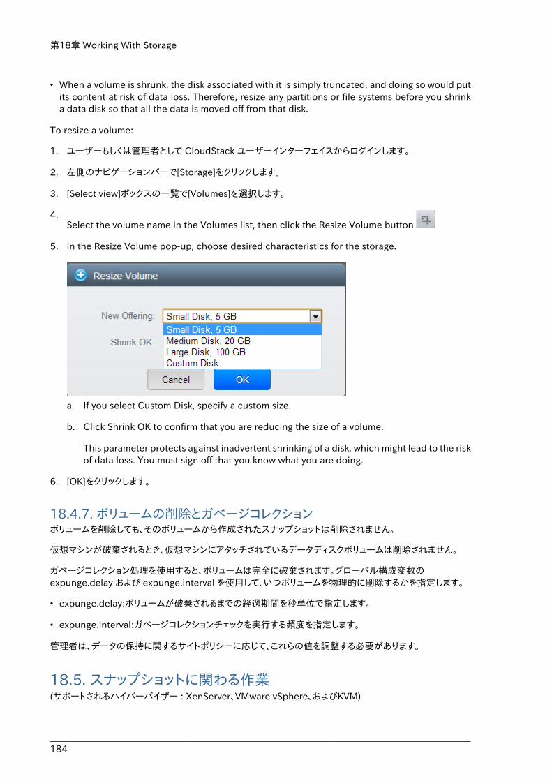
第18章 Working With Storage
184
• When a volume is shrunk, the disk associated with it is simply truncated, and doing so would putits content at risk of data loss. Therefore, resize any partitions or file systems before you shrinka data disk so that all the data is moved off from that disk.
To resize a volume:
1. ユーザーもしくは管理者として CloudStack ユーザーインターフェイスからログインします。
2. 左側のナビゲーションバーで[Storage]をクリックします。
3. [Select view]ボックスの一覧で[Volumes]を選択します。
4.Select the volume name in the Volumes list, then click the Resize Volume button
5. In the Resize Volume pop-up, choose desired characteristics for the storage.
a. If you select Custom Disk, specify a custom size.
b. Click Shrink OK to confirm that you are reducing the size of a volume.
This parameter protects against inadvertent shrinking of a disk, which might lead to the riskof data loss. You must sign off that you know what you are doing.
6. [OK]をクリックします。
18.4.7. ボリュームの削除とガベージコレクションボリュームを削除しても、そのボリュームから作成されたスナップショットは削除されません。
仮想マシンが破棄されるとき、仮想マシンにアタッチされているデータディスクボリュームは削除されません。
ガベージコレクション処理を使用すると、ボリュームは完全に破棄されます。グローバル構成変数のexpunge.delay および expunge.interval を使用して、いつボリュームを物理的に削除するかを指定します。
• expunge.delay:ボリュームが破棄されるまでの経過期間を秒単位で指定します。
• expunge.interval:ガベージコレクションチェックを実行する頻度を指定します。
管理者は、データの保持に関するサイトポリシーに応じて、これらの値を調整する必要があります。
18.5. スナップショットに関わる作業(サポートされるハイパーバイザー : XenServer、VMware vSphere、およびKVM)
Snapshot Job Throttling
185
CloudStack は、ディスクボリュームのスナップショットをサポートします。スナップショットは、仮想マシンディスクの一時点でのキャプチャです。メモリと CPU の状態はキャプチャされません。
ルートディスクとデータディスクの両方を含むボリュームのスナップショットを作成することができます。管理者は、ユーザーごとに格納されるスナップショットの数を制限します。ユーザーは、特定のファイルの復元のために、スナップ ショットから新しいボリュームを作成でき、復元したディスクから起動するために、スナップショットからテンプレートを作成できます。スナップショットを定期的に作成するように設定できます。完成したスナップショットはプライマリストレージからセカ ンダリストレージにコピーされ、削除されるか新しいスナップショットによって消去されるまで格納されます。
ユーザーはスナップショットを手動で作成することも、自動定期スナップショットポリシーをセットアップすることもできます。 ユーザーはスナップショットからディスクボリュームを作成することもでき、そのディスクボリュームはほかのディスクボリュームのように仮想マシンにアタッチできます。ルートディスクとデータディスクの両方のスナップショットがサポートされ ます。ただし現在は、復元されたルートディスクから仮想マシンを起動することはできません。ルートディスクのスナップショットから復元したディスクは通常のデータディスクとして扱われ、復元ディスクのデータは、ディスクを仮想マシンにアタッチすることでアクセスできます。
完成したスナップショットはプライマリストレージからセカンダリストレージにコピーされ、削除されるか新しいスナップショットによって消去されるまで格納されます。
18.5.1. Snapshot Job ThrottlingWhen a snapshot of a virtual machine is requested, the snapshot job runs on the same host wherethe VM is running or, in the case of a stopped VM, the host where it ran last. If many snapshotsare requested for VMs on a single host, this can lead to problems with too many snapshot jobsoverwhelming the resources of the host.
To address this situation, the cloud's root administrator can throttle how many snapshot jobsare executed simultaneously on the hosts in the cloud by using the global configuration settingconcurrent.snapshots.threshold.perhost. By using this setting, the administrator can better ensurethat snapshot jobs do not time out and hypervisor hosts do not experience performance issues dueto hosts being overloaded with too many snapshot requests.
Set concurrent.snapshots.threshold.perhost to a value that represents a best guess about howmany snapshot jobs the hypervisor hosts can execute at one time, given the current resources ofthe hosts and the number of VMs running on the hosts. If a given host has more snapshot requests,the additional requests are placed in a waiting queue. No new snapshot jobs will start until thenumber of currently executing snapshot jobs falls below the configured limit.
The admin can also set job.expire.minutes to place a maximum on how long a snapshot request willwait in the queue. If this limit is reached, the snapshot request fails and returns an error message.
18.5.2. スナップショットの自動作成と保持(サポートされるハイパーバイザー : XenServer、VMware vSphere、および KVM)
ユーザーは、ディスクの複数のスナップショットを定期的に自動作成するように、定期スナップショットポリシーを設定でき ます。スナップショットは、時、日、週、または月単位の間隔で作成できます。スナップショットポリシーは、ディスクボリュームごとに 1 つセットアップできます。たとえば、毎日 02:30 にスナップショットを作成するようにセットアップできます。
スナップショットのスケジュールごとに、保持するスナップショットの数を指定することもできます。保持期限を超過した古いスナップショットは、自動的に削除されます。このユーザーによって定義された期限は CloudStack
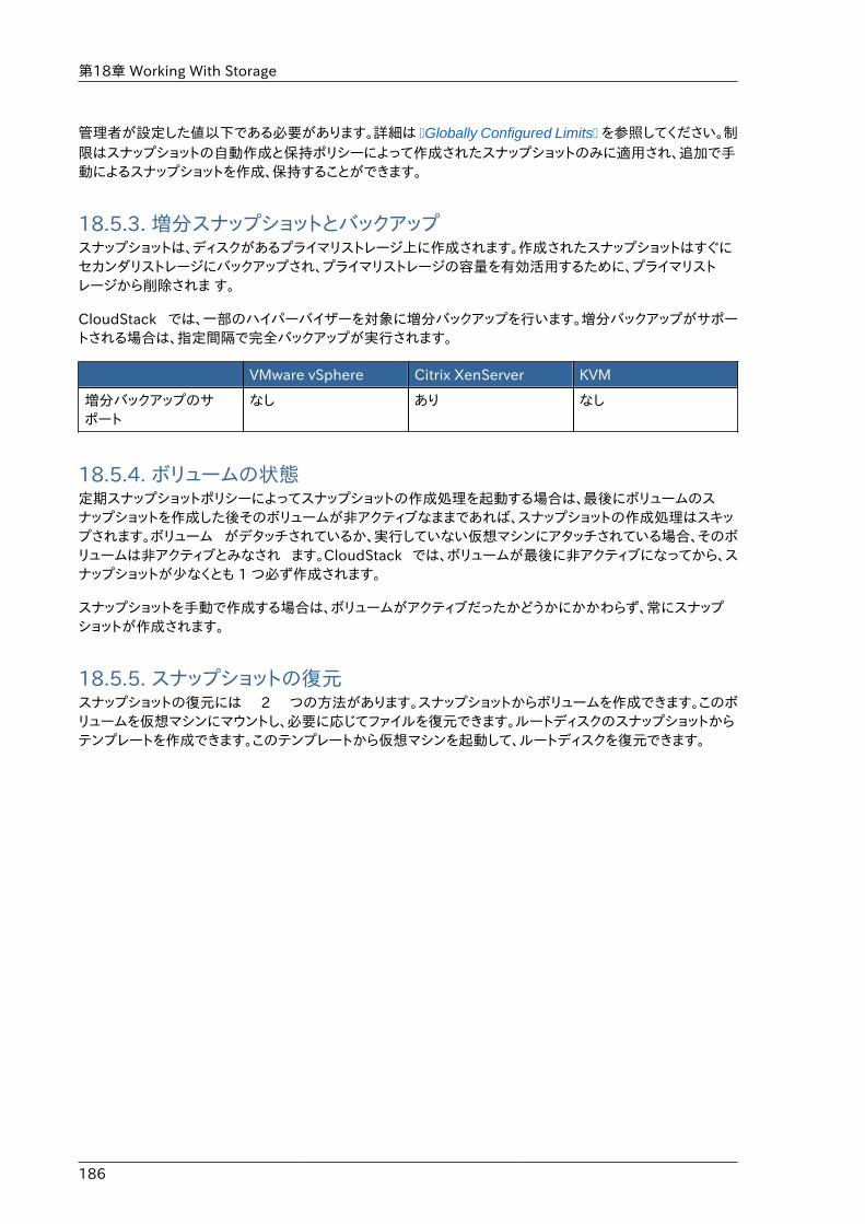
第18章 Working With Storage
186
管理者が設定した値以下である必要があります。詳細は �Globally Configured Limits� を参照してください。制限はスナップショットの自動作成と保持ポリシーによって作成されたスナップショットのみに適用され、追加で手動によるスナップショットを作成、保持することができます。
18.5.3. 増分スナップショットとバックアップスナップショットは、ディスクがあるプライマリストレージ上に作成されます。作成されたスナップショットはすぐにセカンダリストレージにバックアップされ、プライマリストレージの容量を有効活用するために、プライマリストレージから削除されま す。
CloudStack では、一部のハイパーバイザーを対象に増分バックアップを行います。増分バックアップがサポートされる場合は、指定間隔で完全バックアップが実行されます。
VMware vSphere Citrix XenServer KVM
増分バックアップのサポート
なし あり なし
18.5.4. ボリュームの状態定期スナップショットポリシーによってスナップショットの作成処理を起動する場合は、最後にボリュームのスナップショットを作成した後そのボリュームが非アクティブなままであれば、スナップショットの作成処理はスキップされます。ボリューム がデタッチされているか、実行していない仮想マシンにアタッチされている場合、そのボリュームは非アクティブとみなされ ます。CloudStack では、ボリュームが最後に非アクティブになってから、スナップショットが少なくとも 1 つ必ず作成されます。
スナップショットを手動で作成する場合は、ボリュームがアクティブだったかどうかにかかわらず、常にスナップショットが作成されます。
18.5.5. スナップショットの復元スナップショットの復元には 2 つの方法があります。スナップショットからボリュームを作成できます。このボリュームを仮想マシンにマウントし、必要に応じてファイルを復元できます。ルートディスクのスナップショットからテンプレートを作成できます。このテンプレートから仮想マシンを起動して、ルートディスクを復元できます。
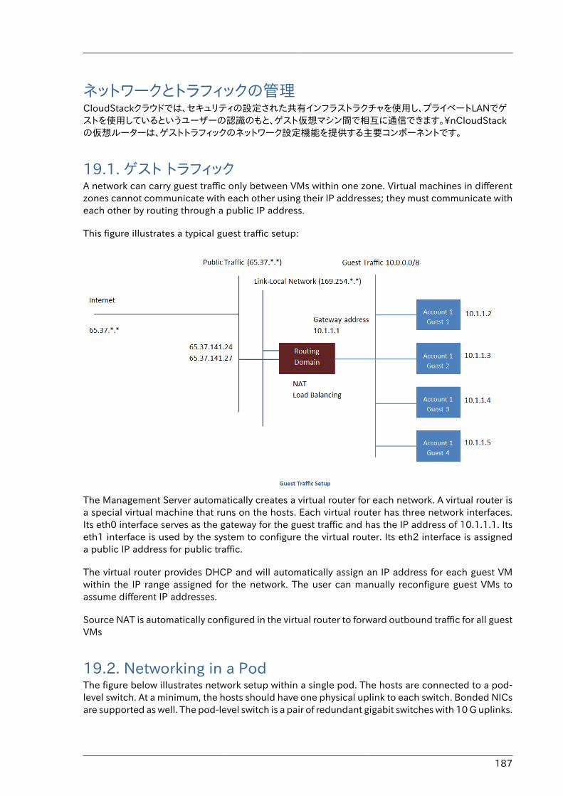
187
ネットワークとトラフィックの管理CloudStackクラウドでは、セキュリティの設定された共有インフラストラクチャを使用し、プライベートLANでゲストを使用しているというユーザーの認識のもと、ゲスト仮想マシン間で相互に通信できます。\nCloudStackの仮想ルーターは、ゲストトラフィックのネットワーク設定機能を提供する主要コンポーネントです。
19.1. ゲスト トラフィックA network can carry guest traffic only between VMs within one zone. Virtual machines in differentzones cannot communicate with each other using their IP addresses; they must communicate witheach other by routing through a public IP address.
This figure illustrates a typical guest traffic setup:
The Management Server automatically creates a virtual router for each network. A virtual router isa special virtual machine that runs on the hosts. Each virtual router has three network interfaces.Its eth0 interface serves as the gateway for the guest traffic and has the IP address of 10.1.1.1. Itseth1 interface is used by the system to configure the virtual router. Its eth2 interface is assigneda public IP address for public traffic.
The virtual router provides DHCP and will automatically assign an IP address for each guest VMwithin the IP range assigned for the network. The user can manually reconfigure guest VMs toassume different IP addresses.
Source NAT is automatically configured in the virtual router to forward outbound traffic for all guestVMs
19.2. Networking in a PodThe figure below illustrates network setup within a single pod. The hosts are connected to a pod-level switch. At a minimum, the hosts should have one physical uplink to each switch. Bonded NICsare supported as well. The pod-level switch is a pair of redundant gigabit switches with 10 G uplinks.
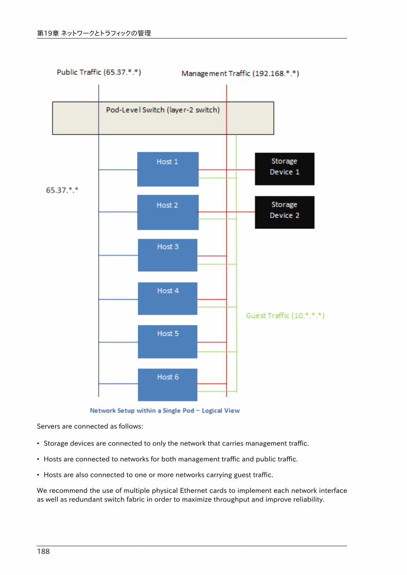
第19章 ネットワークとトラフィックの管理
188
Servers are connected as follows:
• Storage devices are connected to only the network that carries management traffic.
• Hosts are connected to networks for both management traffic and public traffic.
• Hosts are also connected to one or more networks carrying guest traffic.
We recommend the use of multiple physical Ethernet cards to implement each network interfaceas well as redundant switch fabric in order to maximize throughput and improve reliability.
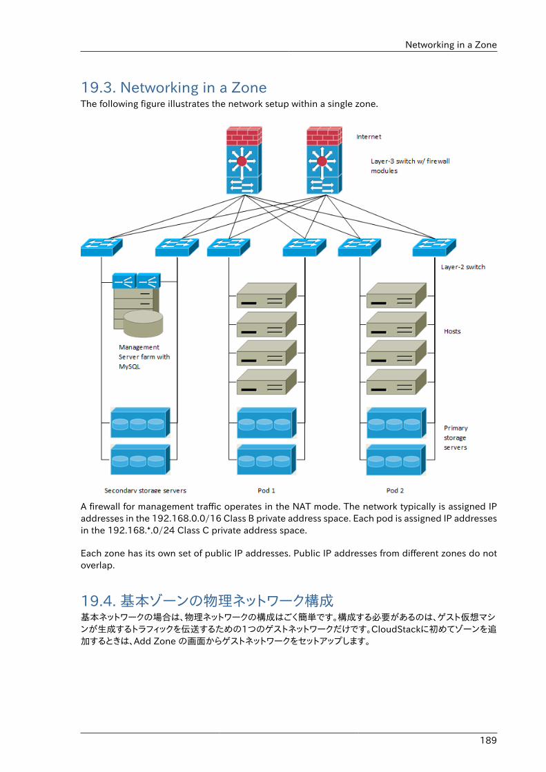
Networking in a Zone
189
19.3. Networking in a ZoneThe following figure illustrates the network setup within a single zone.
A firewall for management traffic operates in the NAT mode. The network typically is assigned IPaddresses in the 192.168.0.0/16 Class B private address space. Each pod is assigned IP addressesin the 192.168.*.0/24 Class C private address space.
Each zone has its own set of public IP addresses. Public IP addresses from different zones do notoverlap.
19.4. 基本ゾーンの物理ネットワーク構成基本ネットワークの場合は、物理ネットワークの構成はごく簡単です。構成する必要があるのは、ゲスト仮想マシンが生成するトラフィックを伝送するための1つのゲストネットワークだけです。CloudStackに初めてゾーンを追加するときは、Add Zone の画面からゲストネットワークをセットアップします。
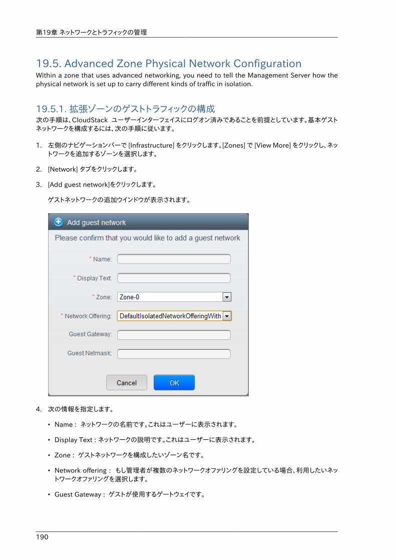
第19章 ネットワークとトラフィックの管理
190
19.5. Advanced Zone Physical Network ConfigurationWithin a zone that uses advanced networking, you need to tell the Management Server how thephysical network is set up to carry different kinds of traffic in isolation.
19.5.1. 拡張ゾーンのゲストトラフィックの構成次の手順は、CloudStack ユーザーインターフェイスにログオン済みであることを前提としています。基本ゲストネットワークを構成するには、次の手順に従います。
1. 左側のナビゲーションバーで [Infrastructure] をクリックします。[Zones] で [View More] をクリックし、ネットワークを追加するゾーンを選択します。
2. [Network] タブをクリックします。
3. [Add guest network]をクリックします。
ゲストネットワークの追加ウインドウが表示されます。
4. 次の情報を指定します。
• Name : ネットワークの名前です。これはユーザーに表示されます。
• Display Text : ネットワークの説明です。これはユーザーに表示されます。
• Zone : ゲストネットワークを構成したいゾーン名です。
• Network offering : もし管理者が複数のネットワークオファリングを設定している場合、利用したいネットワークオファリングを選択します。
• Guest Gateway : ゲストが使用するゲートウェイです。
拡張ゾーンのパブリックトラフィックの構成
191
• Guest Netmask : ゲストの使用するサブネット上で使用されるネットマスクです。
5. 「OK」をクリックします。
19.5.2. 拡張ゾーンのパブリックトラフィックの構成拡張ネットワーク設定を使用するゾーンでは、インターネットトラフィックの IP アドレスの範囲を少なくとも 1 つ構成する必要があります。
19.6. Using Multiple Guest NetworksIn zones that use advanced networking, additional networks for guest traffic may be added at anytime after the initial installation. You can also customize the domain name associated with thenetwork by specifying a DNS suffix for each network.
A VM's networks are defined at VM creation time. A VM cannot add or remove networks after it hasbeen created, although the user can go into the guest and remove the IP address from the NICon a particular network.
Each VM has just one default network. The virtual router's DHCP reply will set the guest's defaultgateway as that for the default network. Multiple non-default networks may be added to a guestin addition to the single, required default network. The administrator can control which networksare available as the default network.
Additional networks can either be available to all accounts or be assigned to a specific account.Networks that are available to all accounts are zone-wide. Any user with access to the zone cancreate a VM with access to that network. These zone-wide networks provide little or no isolationbetween guests.Networks that are assigned to a specific account provide strong isolation.
19.6.1. ゲストネットワークの追加1. 管理者もしくはエンドユーザーとして CloudStack UI にログインします。
2. 左側のナビゲーションから [Network] を選択します。
3. [Add guest network] をクリックし、以下の情報を入力します。
• Name : ネットワークの名前です。この名前はユーザーから見ることができます。
• Display Text : ネットワークの詳細情報です。この情報はユーザーから見ることができます。
• Zone : ネットワークを適用するゾーンの名前です。各ゾーンはゲストネットワークに対し違うIPレンジを持ったブロードキャストドメインに属します。管理者は各ゾーンに対しIPレンジを設定する必要があります。
• Network offering : もし管理者によって複数のネットワークオファリングが設定されている場合、ここで利用したいネットワークを1つ選択します。
• Guest Gateway : ゲストVMが利用するゲートウェイを設定します。
• Guest Netmask : ゲストVMが利用するサブネットのネットマスクを設定します。
4. [Create] をクリックします。
第19章 ネットワークとトラフィックの管理
192
19.6.2. ゲストネットワーク上のネットワークオファリングの変更ユーザーまたは管理者は、既存のゲストネットワークに関連付けられているネットワークオファリングを変更できます。
• 管理者もしくはエンドユーザーとして CloudStack UI にログインします。
• If you are changing from a network offering that uses the CloudStack virtual router to one thatuses external devices as network service providers, you must first stop all the VMs on the network.See "Stopping and Starting Virtual Machines" in the Administrator's Guide.
• 左側のナビゲーションから [Network] を選択します。
• Click the name of the network you want to modify.
•In the Details tab, click Edit.
• [Network Offering]ボックスの一覧で新しいネットワークオファリングを選択して、[Apply]をクリックします。
• A prompt is displayed asking whether you want to keep the existing CIDR. This is to let you knowthat if you change the network offering, the CIDR will be affected. Choose No to proceed withthe change.
• Wait for the update to complete. Don’t try to restart VMs until the network change is complete.
• If you stopped any VMs, restart them.
19.7. セキュリティグループ
19.7.1. セキュリティグループについてセキュリティグループは仮想マシンに対するトラフィックを分離する方法を提供します。セキュリティグループは仮想マシンのグループで、受信規則および送信規則と呼ばれる規則セットに基づいて、受信および送信トラフィックをフィルターします。仮想マシンとの通信を試行するIPアドレスに基づき、これらの規則によってネットワークトラフィックがフィルターされます。セキュリティグループは、基本ネットワーク設定を使用するゾーンで特に便利です。基本ゾーンでは、すべてのゲスト仮想マシンに対して単一のゲストネットワーク提供されるからです。拡張ゾーンでは、KVMハイパーバイザーでのみセキュリティグループがサポートされます。
注記拡張ネットワークを使用すゾーンでは、代わりに複数のゲストネットワークを作成することで、仮想マシンへのトラフィックを隔離します。
各CloudStackアカウントには、すべての受信トラフィックを拒否し、すべての送信トラフィックを許可するデフォルトのセキュリティグループが用意されています。すべての新しい仮想マシンが望ましい規則セットを継承するように、デフォルトのセキュリティグループを変更できます。
CloudStackのユーザーは、任意の数のセキュリティグループを追加できます。新しい仮想マシンには、ユーザー定義のセキュリティグループが別に指定されていない限り、デフォルトのセキュリティグループが起動時に割り当てられます。仮想マシンは、任意の数のセキュリティグループのメンバーになることができます。仮想マシンをセキュリティグループに割り当てると、仮想マシンは有効である限りずっとそのグループに属します。実行中の仮想マシンを別のセキュリティグループに移動することはできません。
セキュリティグループの追加
193
セキュリティグループは、任意の数の受信規則および送信規則を削除または追加することで変更できます。変更後の新しい規則は、実行中または停止中にかかわらず、グループ内のすべての仮想マシンに適用されます。
受信規則を指定しない場合は、送信規則によって送信が許可されているトラフィックへの応答を除いて、トラフィックの受信は許可されません。
19.7.2. セキュリティグループの追加ユーザーもしくは管理者は新しいセキュリティグループを定義することができます。
1. 管理者もしくはエンドユーザーとして CloudStack UI にログインします。
2. 左側のナビゲーションバーで[Network]をクリックします。
3. [Select view]ボックスの一覧で[Security Groups]を選択します。
4. [Add Security Group]をクリックします。
5. 名前と説明を入力します。
6. [OK]をクリックします。
新しいセキュリティグループが[Security Groups Details]タブに表示されます。
7. セキュリティグループを使いやすくするには、「セキュリティグループへの受信規則と送信規則の追加」に進みます。
19.7.3. Security Groups in Advanced Zones (KVM Only)CloudStack provides the ability to use security groups to provide isolation between guests on asingle shared, zone-wide network in an advanced zone where KVM is the hypervisor. Using securitygroups in advanced zones rather than multiple VLANs allows a greater range of options for settingup guest isolation in a cloud.
LimitationsThe following are not supported for this feature:
• Two IP ranges with the same VLAN and different gateway or netmask in security group-enabledshared network.
• Two IP ranges with the same VLAN and different gateway or netmask in account-specific sharednetworks.
• Multiple VLAN ranges in security group-enabled shared network.
• Multiple VLAN ranges in account-specific shared networks.
Security groups must be enabled in the zone in order for this feature to be used.
19.7.4. Enabling Security GroupsIn order for security groups to function in a zone, the security groups feature must first be enabledfor the zone. The administrator can do this when creating a new zone, by selecting a network
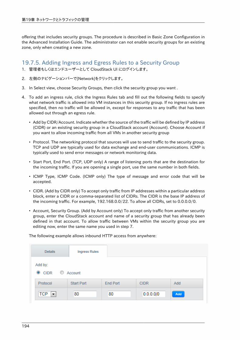
第19章 ネットワークとトラフィックの管理
194
offering that includes security groups. The procedure is described in Basic Zone Configuration inthe Advanced Installation Guide. The administrator can not enable security groups for an existingzone, only when creating a new zone.
19.7.5. Adding Ingress and Egress Rules to a Security Group1. 管理者もしくはエンドユーザーとして CloudStack UI にログインします。
2. 左側のナビゲーションバーで[Network]をクリックします。
3. In Select view, choose Security Groups, then click the security group you want .
4. To add an ingress rule, click the Ingress Rules tab and fill out the following fields to specifywhat network traffic is allowed into VM instances in this security group. If no ingress rules arespecified, then no traffic will be allowed in, except for responses to any traffic that has beenallowed out through an egress rule.
• Add by CIDR/Account. Indicate whether the source of the traffic will be defined by IP address(CIDR) or an existing security group in a CloudStack account (Account). Choose Account ifyou want to allow incoming traffic from all VMs in another security group
• Protocol. The networking protocol that sources will use to send traffic to the security group.TCP and UDP are typically used for data exchange and end-user communications. ICMP istypically used to send error messages or network monitoring data.
• Start Port, End Port. (TCP, UDP only) A range of listening ports that are the destination forthe incoming traffic. If you are opening a single port, use the same number in both fields.
• ICMP Type, ICMP Code. (ICMP only) The type of message and error code that will beaccepted.
• CIDR. (Add by CIDR only) To accept only traffic from IP addresses within a particular addressblock, enter a CIDR or a comma-separated list of CIDRs. The CIDR is the base IP address ofthe incoming traffic. For example, 192.168.0.0/22. To allow all CIDRs, set to 0.0.0.0/0.
• Account, Security Group. (Add by Account only) To accept only traffic from another securitygroup, enter the CloudStack account and name of a security group that has already beendefined in that account. To allow traffic between VMs within the security group you areediting now, enter the same name you used in step 7.
The following example allows inbound HTTP access from anywhere:
External Firewalls and Load Balancers
195
5. To add an egress rule, click the Egress Rules tab and fill out the following fields to specify whattype of traffic is allowed to be sent out of VM instances in this security group. If no egress rulesare specified, then all traffic will be allowed out. Once egress rules are specified, the followingtypes of traffic are allowed out: traffic specified in egress rules; queries to DNS and DHCPservers; and responses to any traffic that has been allowed in through an ingress rule
• Add by CIDR/Account. Indicate whether the destination of the traffic will be defined by IPaddress (CIDR) or an existing security group in a CloudStack account (Account). ChooseAccount if you want to allow outgoing traffic to all VMs in another security group.
• Protocol. The networking protocol that VMs will use to send outgoing traffic. TCP and UDPare typically used for data exchange and end-user communications. ICMP is typically usedto send error messages or network monitoring data.
• Start Port, End Port. (TCP, UDP only) A range of listening ports that are the destination forthe outgoing traffic. If you are opening a single port, use the same number in both fields.
• ICMP Type, ICMP Code. (ICMP only) The type of message and error code that will be sent
• CIDR. (Add by CIDR only) To send traffic only to IP addresses within a particular addressblock, enter a CIDR or a comma-separated list of CIDRs. The CIDR is the base IP address ofthe destination. For example, 192.168.0.0/22. To allow all CIDRs, set to 0.0.0.0/0.
• Account, Security Group. (Add by Account only) To allow traffic to be sent to another securitygroup, enter the CloudStack account and name of a security group that has already beendefined in that account. To allow traffic between VMs within the security group you areediting now, enter its name.
6. [Add]をクリックします。
19.8. External Firewalls and Load BalancersCloudStack is capable of replacing its Virtual Router with an external Juniper SRX device and anoptional external NetScaler or F5 load balancer for gateway and load balancing services. In thiscase, the VMs use the SRX as their gateway.
19.8.1. About Using a NetScaler Load BalancerCitrix NetScaler is supported as an external network element for load balancing in zones that useadvanced networking (also called advanced zones). Set up an external load balancer when youwant to provide load balancing through means other than CloudStack’s provided virtual router.
The NetScaler can be set up in direct (outside the firewall) mode. It must be added before any loadbalancing rules are deployed on guest VMs in the zone.
The functional behavior of the NetScaler with CloudStack is the same as described in theCloudStack documentation for using an F5 external load balancer. The only exception is that theF5 supports routing domains, and NetScaler does not. NetScaler can not yet be used as a firewall.
The Citrix NetScaler comes in three varieties. The following table summarizes how these variantsare treated in CloudStack.
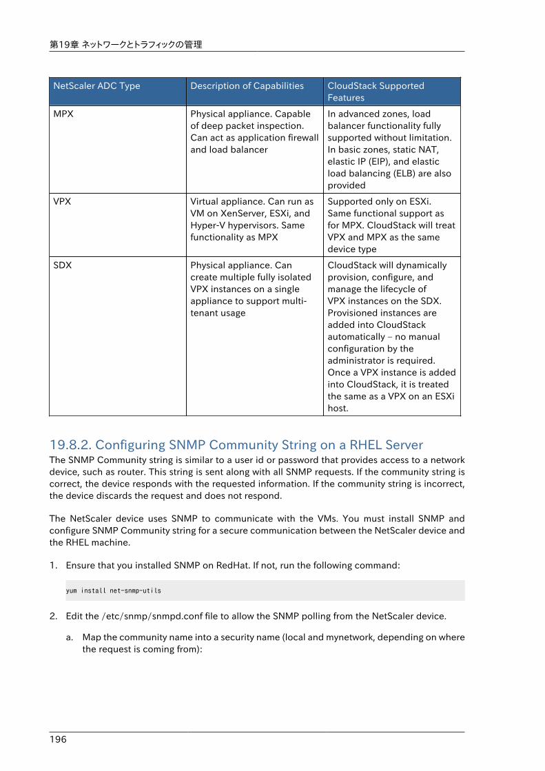
第19章 ネットワークとトラフィックの管理
196
NetScaler ADC Type Description of Capabilities CloudStack SupportedFeatures
MPX Physical appliance. Capableof deep packet inspection.Can act as application firewalland load balancer
In advanced zones, loadbalancer functionality fullysupported without limitation.In basic zones, static NAT,elastic IP (EIP), and elasticload balancing (ELB) are alsoprovided
VPX Virtual appliance. Can run asVM on XenServer, ESXi, andHyper-V hypervisors. Samefunctionality as MPX
Supported only on ESXi.Same functional support asfor MPX. CloudStack will treatVPX and MPX as the samedevice type
SDX Physical appliance. Cancreate multiple fully isolatedVPX instances on a singleappliance to support multi-tenant usage
CloudStack will dynamicallyprovision, configure, andmanage the lifecycle ofVPX instances on the SDX.Provisioned instances areadded into CloudStackautomatically – no manualconfiguration by theadministrator is required.Once a VPX instance is addedinto CloudStack, it is treatedthe same as a VPX on an ESXihost.
19.8.2. Configuring SNMP Community String on a RHEL ServerThe SNMP Community string is similar to a user id or password that provides access to a networkdevice, such as router. This string is sent along with all SNMP requests. If the community string iscorrect, the device responds with the requested information. If the community string is incorrect,the device discards the request and does not respond.
The NetScaler device uses SNMP to communicate with the VMs. You must install SNMP andconfigure SNMP Community string for a secure communication between the NetScaler device andthe RHEL machine.
1. Ensure that you installed SNMP on RedHat. If not, run the following command:
yum install net-snmp-utils
2. Edit the /etc/snmp/snmpd.conf file to allow the SNMP polling from the NetScaler device.
a. Map the community name into a security name (local and mynetwork, depending on wherethe request is coming from):
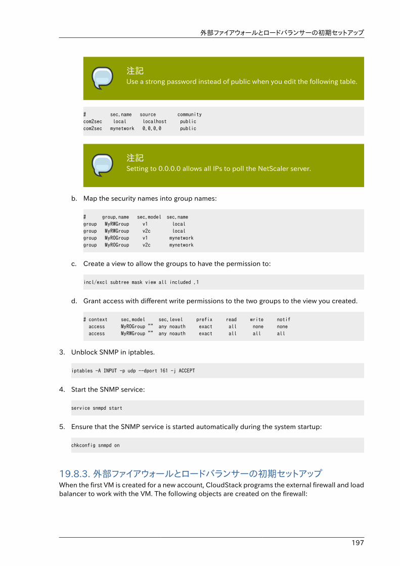
外部ファイアウォールとロードバランサーの初期セットアップ
197
注記Use a strong password instead of public when you edit the following table.
# sec.name source communitycom2sec local localhost publiccom2sec mynetwork 0.0.0.0 public
注記Setting to 0.0.0.0 allows all IPs to poll the NetScaler server.
b. Map the security names into group names:
# group.name sec.model sec.namegroup MyRWGroup v1 localgroup MyRWGroup v2c localgroup MyROGroup v1 mynetworkgroup MyROGroup v2c mynetwork
c. Create a view to allow the groups to have the permission to:
incl/excl subtree mask view all included .1
d. Grant access with different write permissions to the two groups to the view you created.
# context sec.model sec.level prefix read write notif access MyROGroup "" any noauth exact all none none access MyRWGroup "" any noauth exact all all all
3. Unblock SNMP in iptables.
iptables -A INPUT -p udp --dport 161 -j ACCEPT
4. Start the SNMP service:
service snmpd start
5. Ensure that the SNMP service is started automatically during the system startup:
chkconfig snmpd on
19.8.3. 外部ファイアウォールとロードバランサーの初期セットアップWhen the first VM is created for a new account, CloudStack programs the external firewall and loadbalancer to work with the VM. The following objects are created on the firewall:
第19章 ネットワークとトラフィックの管理
198
• A new logical interface to connect to the account's private VLAN. The interface IP is always thefirst IP of the account's private subnet (e.g. 10.1.1.1).
• A source NAT rule that forwards all outgoing traffic from the account's private VLAN to the publicInternet, using the account's public IP address as the source address
• A firewall filter counter that measures the number of bytes of outgoing traffic for the account
The following objects are created on the load balancer:
• A new VLAN that matches the account's provisioned Zone VLAN
• A self IP for the VLAN. This is always the second IP of the account's private subnet (e.g. 10.1.1.2).
19.8.4. Ongoing Configuration of External Firewalls and LoadBalancersAdditional user actions (e.g. setting a port forward) will cause further programming of the firewalland load balancer. A user may request additional public IP addresses and forward traffic receivedat these IPs to specific VMs. This is accomplished by enabling static NAT for a public IP address,assigning the IP to a VM, and specifying a set of protocols and port ranges to open. When a staticNAT rule is created, CloudStack programs the zone's external firewall with the following objects:
• A static NAT rule that maps the public IP address to the private IP address of a VM.
• A security policy that allows traffic within the set of protocols and port ranges that are specified.
• A firewall filter counter that measures the number of bytes of incoming traffic to the public IP.
The number of incoming and outgoing bytes through source NAT, static NAT, and load balancingrules is measured and saved on each external element. This data is collected on a regular basisand stored in the CloudStack database.
19.8.5. Configuring AutoScaleAutoScaling allows you to scale your back-end services or application VMs up or down seamlesslyand automatically according to the conditions you define. With AutoScaling enabled, you canensure that the number of VMs you are using seamlessly scale up when demand increases, andautomatically decreases when demand subsides. Using AutoScaling, you can automatically shutdown instances you don't need, or launch new instances, depending on demand.
NetScaler AutoScaling is designed to seamlessly launch or terminate VMs based on user-definedconditions. Conditions for triggering a scaleup or scaledown action can vary from a simple use caselike monitoring the CPU usage of a server to a complex use case of monitoring a combination ofserver's responsiveness and its CPU usage. For example, you can configure AutoScaling to launchan additional VM whenever CPU usage exceeds 80 percent for 15 minutes, or to remove a VMwhenever CPU usage is less than 20 percent for 30 minutes.
CloudStack uses the NetScaler load balancer to monitor all aspects of a system's health and workin unison with CloudStack to initiate scale-up or scale-down actions.
Configuring AutoScale
199
注記AutoScale is supported on NetScaler Release 10 Build 73.e and beyond.
事前準備Before you configure an AutoScale rule, consider the following:
• Ensure that the necessary template is prepared before configuring AutoScale. When a VM isdeployed by using a template and when it comes up, the application should be up and running.
注記If the application is not running, the NetScaler device considers the VMas ineffective and continues provisioning the VMs unconditionally until theresource limit is exhausted.
• Deploy the templates you prepared. Ensure that the applications come up on the first boot andis ready to take the traffic. Observe the time requires to deploy the template. Consider this timewhen you specify the quiet time while configuring AutoScale.
• The AutoScale feature supports the SNMP counters that can be used to define conditionsfor taking scale up or scale down actions. To monitor the SNMP-based counter, ensure thatthe SNMP agent is installed in the template used for creating the AutoScale VMs, and theSNMP operations work with the configured SNMP community and port by using standard SNMPmanagers. For example, see �Configuring SNMP Community String on a RHEL Server� to configureSNMP on a RHEL machine.
• Ensure that the endpointe.url parameter present in the Global Settings is set to theManagement Server API URL. For example, http://10.102.102.22:8080/client/api. In a multi-node Management Server deployment, use the virtual IP address configured in the load balancerfor the management server’s cluster. Additionally, ensure that the NetScaler device has accessto this IP address to provide AutoScale support.
If you update the endpointe.url, disable the AutoScale functionality of the load balancer rulesin the system, then enable them back to reflect the changes. For more information see Updatingan AutoScale Configuration
• If the API Key and Secret Key are regenerated for an AutoScale user, ensure that the AutoScalefunctionality of the load balancers that the user participates in are disabled and then enabled toreflect the configuration changes in the NetScaler.
• In an advanced Zone, ensure that at least one VM should be present before configuring a loadbalancer rule with AutoScale. Having one VM in the network ensures that the network is inimplemented state for configuring AutoScale.
構成以下の要素を指定します。
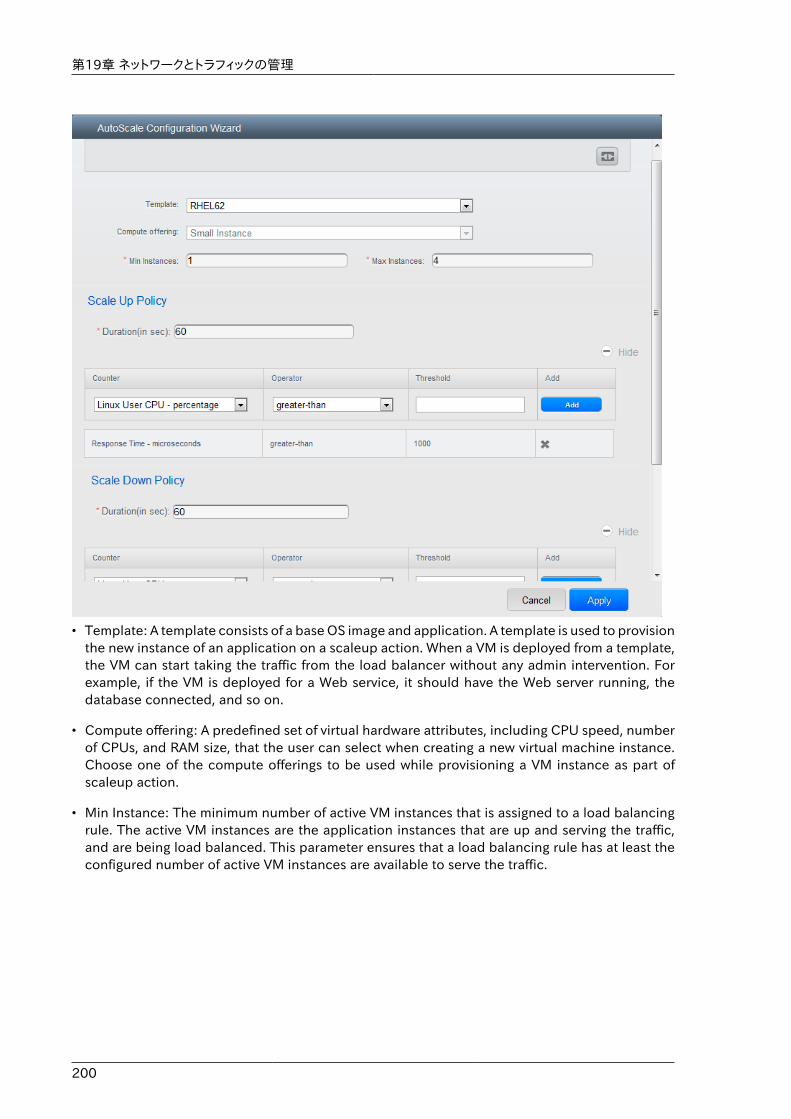
第19章 ネットワークとトラフィックの管理
200
• Template: A template consists of a base OS image and application. A template is used to provisionthe new instance of an application on a scaleup action. When a VM is deployed from a template,the VM can start taking the traffic from the load balancer without any admin intervention. Forexample, if the VM is deployed for a Web service, it should have the Web server running, thedatabase connected, and so on.
• Compute offering: A predefined set of virtual hardware attributes, including CPU speed, numberof CPUs, and RAM size, that the user can select when creating a new virtual machine instance.Choose one of the compute offerings to be used while provisioning a VM instance as part ofscaleup action.
• Min Instance: The minimum number of active VM instances that is assigned to a load balancingrule. The active VM instances are the application instances that are up and serving the traffic,and are being load balanced. This parameter ensures that a load balancing rule has at least theconfigured number of active VM instances are available to serve the traffic.
Configuring AutoScale
201
注記If an application, such as SAP, running on a VM instance is down for some reason,the VM is then not counted as part of Min Instance parameter, and the AutoScalefeature initiates a scaleup action if the number of active VM instances is belowthe configured value. Similarly, when an application instance comes up fromits earlier down state, this application instance is counted as part of the activeinstance count and the AutoScale process initiates a scaledown action when theactive instance count breaches the Max instance value.
• Max Instance: Maximum number of active VM instances that should be assigned to a loadbalancing rule. This parameter defines the upper limit of active VM instances that can be assignedto a load balancing rule.
Specifying a large value for the maximum instance parameter might result in provisioning largenumber of VM instances, which in turn leads to a single load balancing rule exhausting the VMinstances limit specified at the account or domain level.
注記If an application, such as SAP, running on a VM instance is down for some reason,the VM is not counted as part of Max Instance parameter. So there may bescenarios where the number of VMs provisioned for a scaleup action might bemore than the configured Max Instance value. Once the application instances inthe VMs are up from an earlier down state, the AutoScale feature starts aligningto the configured Max Instance value.
Specify the following scale-up and scale-down policies:
• Duration: The duration, in seconds, for which the conditions you specify must be true to triggera scaleup action. The conditions defined should hold true for the entire duration you specify foran AutoScale action to be invoked.
• Counter: The performance counters expose the state of the monitored instances. By default,CloudStack offers four performance counters: Three SNMP counters and one NetScaler counter.The SNMP counters are Linux User CPU, Linux System CPU, and Linux CPU Idle. The NetScalercounter is ResponseTime. The root administrator can add additional counters into CloudStackby using the CloudStack API.
• Operator: The following five relational operators are supported in AutoScale feature: Greaterthan, Less than, Less than or equal to, Greater than or equal to, and Equal to.
• Threshold: Threshold value to be used for the counter. Once the counter defined above breachesthe threshold value, the AutoScale feature initiates a scaleup or scaledown action.
• Add: Click Add to add the condition.
Additionally, if you want to configure the advanced settings, click Show advanced settings, andspecify the following:
第19章 ネットワークとトラフィックの管理
202
• Polling interval: Frequency in which the conditions, combination of counter, operator andthreshold, are to be evaluated before taking a scale up or down action. The default polling intervalis 30 seconds.
• Quiet Time: This is the cool down period after an AutoScale action is initiated. The time includesthe time taken to complete provisioning a VM instance from its template and the time taken byan application to be ready to serve traffic. This quiet time allows the fleet to come up to a stablestate before any action can take place. The default is 300 seconds.
• Destroy VM Grace Period: The duration in seconds, after a scaledown action is initiated, to waitbefore the VM is destroyed as part of scaledown action. This is to ensure graceful close of anypending sessions or transactions being served by the VM marked for destroy. The default is 120seconds.
• Security Groups: Security groups provide a way to isolate traffic to the VM instances. A securitygroup is a group of VMs that filter their incoming and outgoing traffic according to a set of rules,called ingress and egress rules. These rules filter network traffic according to the IP address thatis attempting to communicate with the VM.
• Disk Offerings: A predefined set of disk size for primary data storage.
• SNMP Community: The SNMP community string to be used by the NetScaler device to query theconfigured counter value from the provisioned VM instances. Default is public.
• SNMP Port: The port number on which the SNMP agent that run on the provisioned VMs islistening. Default port is 161.
• User: This is the user that the NetScaler device use to invoke scaleup and scaledown API callsto the cloud. If no option is specified, the user who configures AutoScaling is applied. Specifyanother user name to override.
• Apply: Click Apply to create the AutoScale configuration.
Disabling and Enabling an AutoScale ConfigurationIf you want to perform any maintenance operation on the AutoScale VM instances, disable theAutoScale configuration. When the AutoScale configuration is disabled, no scaleup or scaledownaction is performed. You can use this downtime for the maintenance activities. To disable the
AutoScale configuration, click the Disable AutoScale button.
The button toggles between enable and disable, depending on whether AutoScale is currentlyenabled or not. After the maintenance operations are done, you can enable the AutoScaleconfiguration back. To enable, open the AutoScale configuration page again, then click the Enable
AutoScale button.
Updating an AutoScale ConfigurationYou can update the various parameters and add or delete the conditions in a scaleup or scaledownrule. Before you update an AutoScale configuration, ensure that you disable the AutoScale loadbalancer rule by clicking the Disable AutoScale button.
After you modify the required AutoScale parameters, click Apply. To apply the new AutoScalepolicies, open the AutoScale configuration page again, then click the Enable AutoScale button.
負荷分散のルール
203
Runtime Considerations
• An administrator should not assign a VM to a load balancing rule which is configured forAutoScale.
• Before a VM provisioning is completed if NetScaler is shutdown or restarted, the provisioned VMcannot be a part of the load balancing rule though the intent was to assign it to a load balancingrule. To workaround, rename the AutoScale provisioned VMs based on the rule name or ID so atany point of time the VMs can be reconciled to its load balancing rule.
• Making API calls outside the context of AutoScale, such as destroyVM, on an autoscaled VMleaves the load balancing configuration in an inconsistent state. Though VM is destroyed fromthe load balancer rule, NetScaler continues to show the VM as a service assigned to a rule.
19.9. 負荷分散のルールCloudStack ユーザーもしくは管理者はパブリックIPから1つもしくは複数の仮想マシンへの受信トラフィックの分散のため負荷分散ルールを作成するかもしれません。ユーザーは特定のアルゴリズムに基づきルールを作成し仮想マシンのセットに対して割り当てます。
注記もし、負荷分散ルールを作成する際 NetScaler のような外部デバイスを含んだネットワークサービスオファリングを利用していた場合、また後にネットワークサービスオファリングをCloudStack の仮想ルーターを利用するよう変更を加える場合、継続して機能を利用するためには全ての負荷分散ルールに対しファイアウォールルールを追加しなければなりません。
19.9.1. ロードバランサールールの追加1. 管理者もしくはエンドユーザーとして CloudStack UI にログインします。
2. 左側のナビゲーションから [Network] を選択します。
3. トラフィックの負荷分散をしたいしたいネットワークの名前をクリックします。
4. [View IP Addresses] をクリックします。
5. ルールを作成したい IP アドレスをクリックし、[Configuration] タブをクリックします。
6. 構成図のロードバランサーをクリックし、[View All] をクリックします。
基本ゾーンでは IP アドレスを選択せずに負荷分散ルールを作成することもできます。 CloudStack は負荷分散ルールの作成時に内部的に IP を割り当て、ルール作成時に割り当てられた IP アドレスがリスト表示されます。
ネットワークの名前を選択し、[Add Load Balancer] タブをクリックします。詳細は 7 を参照してください。
7. 次の項目を入力します。
• Name : 負荷分散ルールの名前です。
• Public Port : 負荷分散のための入力トラフィックを受信するポート番号です。
第19章 ネットワークとトラフィックの管理
204
• Private Port : 仮想マシンがトラフィックを受信するポート番号です。
• Algorithm : CloudStack で利用したい負荷分散アルゴリズムを選択します。 CloudStack では様々なアルゴリズムをサポートしています。 これらのアルゴリズムに関して詳細を知りたい場合はインターネット上でより多くの情報を取得できます。
• Stickiness : (オプション) [Configure] をクリックし、スティックネスポリシーを選択します。詳細は「Sticky Session Policies for Load Balancer Rules」を参照してください。
• AutoScale: [Configure] をクリックし �Configuring AutoScale� に従ってオートスケールの設定を完了します。
8. [Add VMs] をクリックした後入力トラフィックの負荷を分散する2つ以上の仮想マシンを選択し、[Apply] をクリックします。
新しい負荷分散ルールがリスト表示され、IP アドレスに対する負荷分散ルールを引き続き追加することができます。
19.9.2. Sticky Session Policies for Load Balancer RulesSticky sessions are used in Web-based applications to ensure continued availability of informationacross the multiple requests in a user's session. For example, if a shopper is filling a cart, you needto remember what has been purchased so far. The concept of "stickiness" is also referred to aspersistence or maintaining state.
Any load balancer rule defined in CloudStack can have a stickiness policy. The policy consists ofa name, stickiness method, and parameters. The parameters are name-value pairs or flags, whichare defined by the load balancer vendor. The stickiness method could be load balancer-generatedcookie, application-generated cookie, or source-based. In the source-based method, the source IPaddress is used to identify the user and locate the user’s stored data. In the other methods, cookiesare used. The cookie generated by the load balancer or application is included in request andresponse URLs to create persistence. The cookie name can be specified by the administrator orautomatically generated. A variety of options are provided to control the exact behavior of cookies,such as how they are generated and whether they are cached.
For the most up to date list of available stickiness methods, see the CloudStack UI or calllistNetworks and check the SupportedStickinessMethods capability.
19.10. Guest IP RangesThe IP ranges for guest network traffic are set on a per-account basis by the user. This allowsthe users to configure their network in a fashion that will enable VPN linking between their guestnetwork and their clients.
19.11. 新しい IP アドレスの取得1. 管理者もしくはエンドユーザーとして CloudStack UI にログインします。
2. 左側のナビゲーションから [Network] を選択します。
3. 変更したいネットワークの名前をクリックします。
4. [View IP Addresses] をクリックします。
IP アドレスの開放
205
5. [Acquire New IP] をクリックし、確認ダイアログで [Yes] をクリックします。
一般的に IP アドレスは有限のリソースであるため確認を求められます。しばらくするとステータスが「Allocated」となり新しい IP アドレスが表示されます。これで新しい IP アドレスをポートフォワーディングやスタティック NAT ルールに利用できます。
19.12. IP アドレスの開放When the last rule for an IP address is removed, you can release that IP address. The IP addressstill belongs to the VPC; however, it can be picked up for any guest network again.
1. 管理者またはユーザーとして CloudStack ユーザーインターフェイスにログオンします。
2. 左側のナビゲーションから [Network] を選択します。
3. 変更したいネットワークの名前をクリックします。
4. [View IP Addresses] をクリックします。
5. 開放したい IP アドレスをクリックします。
6.Click the Release IP button.
19.13. 静的 NATA static NAT rule maps a public IP address to the private IP address of a VM in order to allow Internettraffic into the VM. The public IP address always remains the same, which is why it is called “static”NAT. This section tells how to enable or disable static NAT for a particular IP address.
19.13.1. スタティック NAT の有効化、無効化もし、すでにポートフォワーディングのルールが IP アドレスに反映されている場合、IP に対してスタティック NATを有効化することができません。
仮想マシンがいくつかのネットワークに所属している場合、スタティック NAT のルールは デフォルトネットワークでしか機能しません。
1. 管理者もしくはエンドユーザーとして CloudStack UI にログインします。
2. 左側のナビゲーションから [Network] を選択します。
3. 変更したいネットワークの名前をクリックします。
4. [View IP Addresses] をクリックします。
5. 変更したい IP アドレスをクリックします。
6.Click the Static NAT button.
The button toggles between Enable and Disable, depending on whether static NAT is currentlyenabled for the IP address.
7. If you are enabling static NAT, a dialog appears where you can choose the destination VM andclick Apply.
第19章 ネットワークとトラフィックの管理
206
19.14. IP Forwarding and FirewallingBy default, all incoming traffic to the public IP address is rejected. All outgoing traffic from theguests is also blocked by default.
To allow outgoing traffic, follow the procedure in �Creating Egress Firewall Rules in an AdvancedZone�.
To allow incoming traffic, users may set up firewall rules and/or port forwarding rules. For example,you can use a firewall rule to open a range of ports on the public IP address, such as 33 through 44.Then use port forwarding rules to direct traffic from individual ports within that range to specificports on user VMs. For example, one port forwarding rule could route incoming traffic on the publicIP's port 33 to port 100 on one user VM's private IP. For more information, see ������������� and �������.
19.14.1. Creating Egress Firewall Rules in an Advanced Zone
注記The egress firewall rules are supported only on virtual routers.
The egress traffic originates from a private network to a public network, such as the Internet. Bydefault, the egress traffic is blocked, so no outgoing traffic is allowed from a guest network to theInternet. However, you can control the egress traffic in an Advanced zone by creating egress firewallrules. When an egress firewall rule is applied, the traffic specific to the rule is allowed and theremaining traffic is blocked. When all the firewall rules are removed the default policy, Block, isapplied.
Consider the following scenarios to apply egress firewall rules:
• Allow the egress traffic from specified source CIDR. The Source CIDR is part of guest networkCIDR.
• Allow the egress traffic with destination protocol TCP,UDP,ICMP, or ALL.
• Allow the egress traffic with destination protocol and port range. The port range is specified forTCP, UDP or for ICMP type and code.
To configure an egress firewall rule:
1. 管理者またはユーザーとして CloudStack ユーザーインターフェイスにログオンします。
2. 左側のナビゲーションから [Network] を選択します。
3. In Select view, choose Guest networks, then click the Guest network you want.
4. To add an egress rule, click the Egress rules tab and fill out the following fields to specify whattype of traffic is allowed to be sent out of VM instances in this guest network:
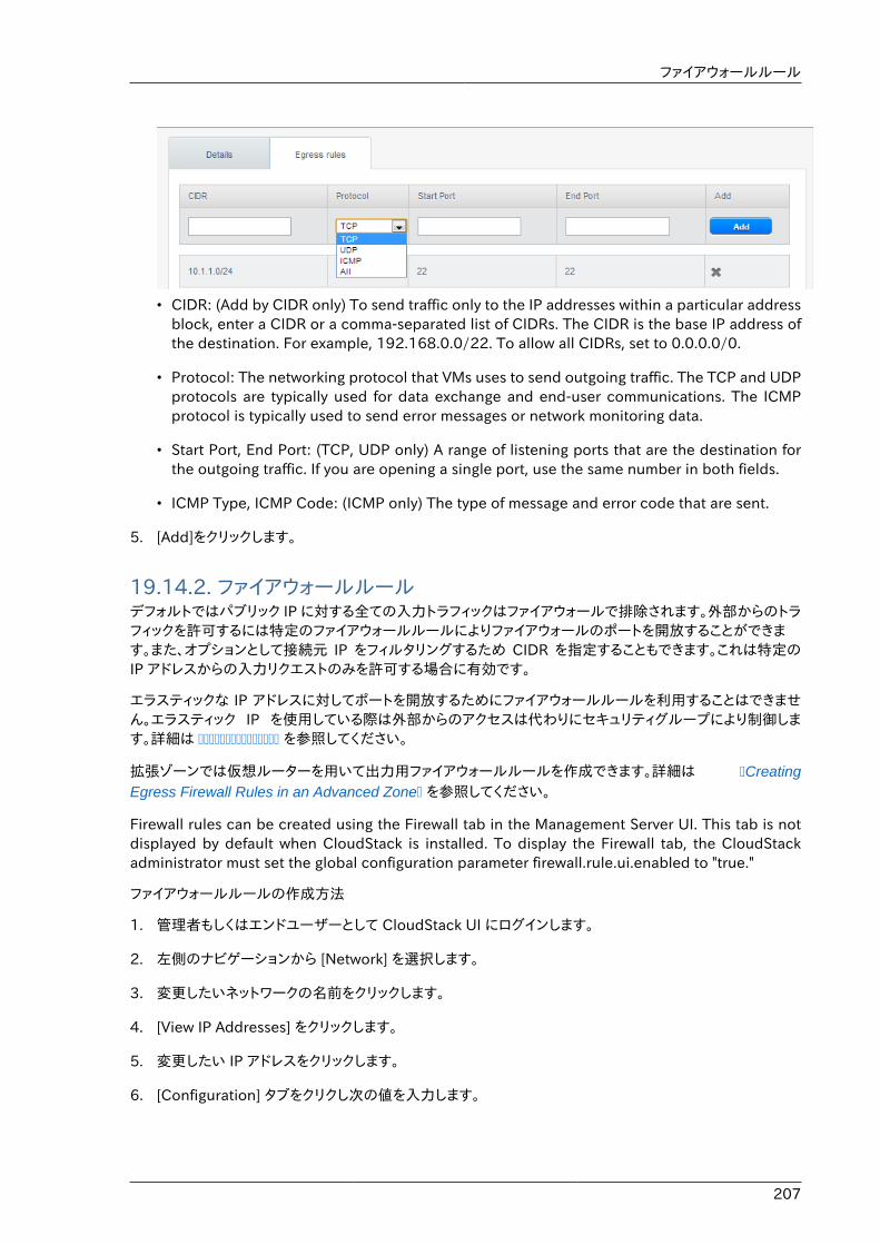
ファイアウォールルール
207
• CIDR: (Add by CIDR only) To send traffic only to the IP addresses within a particular addressblock, enter a CIDR or a comma-separated list of CIDRs. The CIDR is the base IP address ofthe destination. For example, 192.168.0.0/22. To allow all CIDRs, set to 0.0.0.0/0.
• Protocol: The networking protocol that VMs uses to send outgoing traffic. The TCP and UDPprotocols are typically used for data exchange and end-user communications. The ICMPprotocol is typically used to send error messages or network monitoring data.
• Start Port, End Port: (TCP, UDP only) A range of listening ports that are the destination forthe outgoing traffic. If you are opening a single port, use the same number in both fields.
• ICMP Type, ICMP Code: (ICMP only) The type of message and error code that are sent.
5. [Add]をクリックします。
19.14.2. ファイアウォールルールデフォルトではパブリック IP に対する全ての入力トラフィックはファイアウォールで排除されます。外部からのトラフィックを許可するには特定のファイアウォールルールによりファイアウォールのポートを開放することができます。また、オプションとして接続元 IP をフィルタリングするため CIDR を指定することもできます。これは特定のIP アドレスからの入力リクエストのみを許可する場合に有効です。
エラスティックな IP アドレスに対してポートを開放するためにファイアウォールルールを利用することはできません。エラスティック IP を使用している際は外部からのアクセスは代わりにセキュリティグループにより制御します。詳細は ��������������� を参照してください。
拡張ゾーンでは仮想ルーターを用いて出力用ファイアウォールルールを作成できます。詳細は �CreatingEgress Firewall Rules in an Advanced Zone� を参照してください。
Firewall rules can be created using the Firewall tab in the Management Server UI. This tab is notdisplayed by default when CloudStack is installed. To display the Firewall tab, the CloudStackadministrator must set the global configuration parameter firewall.rule.ui.enabled to "true."
ファイアウォールルールの作成方法
1. 管理者もしくはエンドユーザーとして CloudStack UI にログインします。
2. 左側のナビゲーションから [Network] を選択します。
3. 変更したいネットワークの名前をクリックします。
4. [View IP Addresses] をクリックします。
5. 変更したい IP アドレスをクリックします。
6. [Configuration] タブをクリクし次の値を入力します。
第19章 ネットワークとトラフィックの管理
208
• Source CIDR : (オプション) 特定のアドレスブロックに含まれる IP アドレスのみを許可するには CIDRかカンマで区切られた CIDR のリストを入力します。 例として 192.168.0.0/22 などが挙げられます。また、空欄にすると全ての CIDR を許可します。
• Protocol : 開放されたポートで利用される通信プロトコルです。
• Start Port と End Port : ファイアウォールで開放したいポート番号です。単一のポートを開放したい場合、両方のフィールドに同一の番号を入力してください。
• ICMP Type と ICMP Code : プロトコルに ICMP を設定した場合のみ利用されます。ICMP プロトコルにおいて必要な ICMP ヘッダーに埋め込まれるタイプとコードを入力してください。何を入力するべきか詳細に関しては 「ICMP ドキュメント」を参照してください。
7. [Add]をクリックします。
19.14.3. ポート転送ポート転送サービスは、ポリシーを定義するポート転送規則のセットです。ポート転送サービスは、1 台または複数のゲスト仮想マシンに適用されます。これにより、ゲスト仮想マシンに、ポート転送サービスで定義するポリシーに従って管理される受信ネットワークアクセス権が付与されます。オプションで、CIDR を指定して送信元 IPアドレスをフィルターすることもで きます。これは、特定の IP アドレスからの受信要求の転送のみを許可する場合に役立ちます。
任意の数のポート転送サービスを、ゲスト仮想マシンに適用できます。ポート転送サービスは定義できますが、メンバーを持つものではありません。
エラスティック IP に対してはポートを開放するためにポート転送を利用することができません。エラスティックIP を使っている場合は代わりにセキュリティグループを使って外部からのアクセスをコントロールします。詳細は「セキュリティグループ」を参照してください。
ポート転送を設定するには
1. 管理者もしくはエンドユーザーとして CloudStack UI にログインします。
2. もし、完了しない場合は CloudStack でパブリック IP アドレスの範囲をゾーンに追加します。詳細はインストールガイドの「ゾーンとポッドの追加」を参照してください。
3. 1 台または複数のゲスト仮想マシンを CloudStack に追加してください。
4. 左側のナビゲーションバーで[Network]をクリックします。
5. 仮想マシンを実行しているゲストネットワークの名前をクリックします。
6. 既存の IP アドレスを選択するか、新しい IP アドレスを取得します(���� IP �������� を参照)。一覧内の IP アドレスをクリックします。
7. [Configuration]タブをクリックします。
8. ダイアグラムの[Port Forwarding]ノードの[View All]をクリックします。
9. 次の項目を入力します。
• Public Port : パブリックトラフィックが送信される、前の手順で取得した IP アドレスのポートです。
• Private Port : 転送されたパブリックトラフィックをインスタンスがリッスンするポートです。
IP Load Balancing
209
• Protocol: 2 つのポートの間で使用される通信プロトコルです。
10. [Add]をクリックします。
19.15. IP Load BalancingThe user may choose to associate the same public IP for multiple guests. CloudStack implementsa TCP-level load balancer with the following policies.
• ラウンドロビン
• Least connection
• Source IP
This is similar to port forwarding but the destination may be multiple IP addresses.
19.16. DNSとDHCP仮想ルータはゲストに DNS と DHCP サービスを提供します。有効なゾーンにある DNS サーバへ DNS リクエストをプロクシします。
19.17. VPNCloudStack アカウントの所有者は、仮想マシンにアクセスするためのVPN(Virtual Private Network:仮想プライベートネットワーク)を作成できます。リモートアクセス VPN サービスを提供するネットワークオファリングからゲストネットワークのインスタンスを作成すると、システム仮想マシンに基づいて、仮想ルーターによってサービスが提供されます。\nCloudStack は、L2TP over IPsec ベースのリモートアクセス VPN サービ スをゲスト仮想ネットワークに提供します。各ネットワークに仮想ルー\nターがあるため、VPN はネットワーク間で共有されません。Windows、Mac OS X、および iOS のネイティブ VPN クライアントを使用して、ゲストネットワークに接続できます。アカウント所有者は VPN ユーザーを作成して管理することができます。このために、CloudStack のアカウントデータベースではなく別のテーブルが使用されます。VPN ユーザーデータベースは、 特定のアカウント所有者が作成するすべての VPN で共有されます。すべての VPN ユーザーはそのアカウント所有者が作成するすべての VPN にアクセスできます。
注記トラフィックのすべてが VPN を経由するわけ はないことに注意してください。つまり、VPN によって構築されるルートはゲストネットワーク専用にする必要があり、すべてのトラフィックに使用できるわけではありません。
• モバイルユーザー/リモートアクセス : ユーザーは、自宅または事務所からクラウド内のプライベートネットワーク に安全に接続することを望んでいます。通常、接続するクライアントの IP アドレスは動的であり、VPNサーバーで事前構成することはできません。
• Site to Site. In this scenario, two private subnets are connected over the public Internet witha secure VPN tunnel. The cloud user’s subnet (for example, an office network) is connectedthrough a gateway to the network in the cloud. The address of the user’s gateway must bepreconfigured on the VPN server in the cloud. Note that although L2TP-over-IPsec can be usedto set up Site-to-Site VPNs, this is not the primary intent of this feature. For more information,see �Setting Up a Site-to-Site VPN Connection�
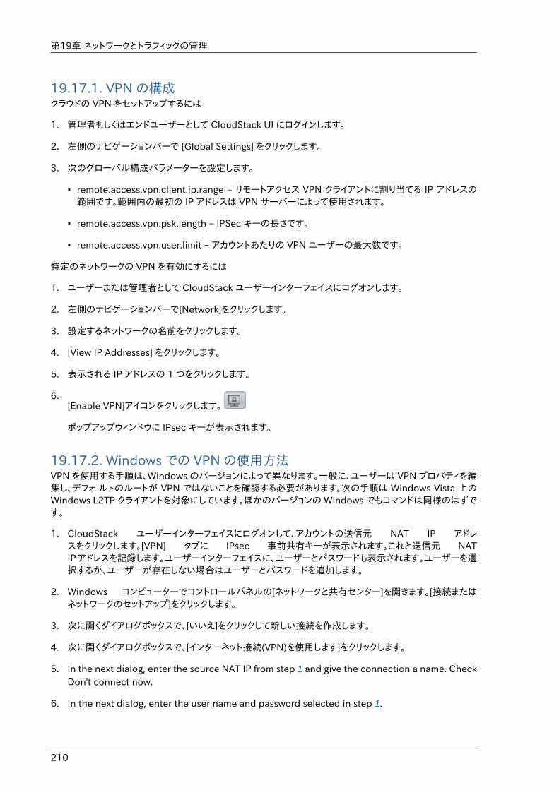
第19章 ネットワークとトラフィックの管理
210
19.17.1. VPN の構成クラウドの VPN をセットアップするには
1. 管理者もしくはエンドユーザーとして CloudStack UI にログインします。
2. 左側のナビゲーションバーで [Global Settings] をクリックします。
3. 次のグローバル構成パラメーターを設定します。
• remote.access.vpn.client.ip.range – リモートアクセス VPN クライアントに割り当てる IP アドレスの範囲です。範囲内の最初の IP アドレスは VPN サーバーによって使用されます。
• remote.access.vpn.psk.length – IPSec キーの長さです。
• remote.access.vpn.user.limit – アカウントあたりの VPN ユーザーの最大数です。
特定のネットワークの VPN を有効にするには
1. ユーザーまたは管理者として CloudStack ユーザーインターフェイスにログオンします。
2. 左側のナビゲーションバーで[Network]をクリックします。
3. 設定するネットワークの名前をクリックします。
4. [View IP Addresses] をクリックします。
5. 表示される IP アドレスの 1 つをクリックします。
6.[Enable VPN]アイコンをクリックします。
ポップアップウィンドウに IPsec キーが表示されます。
19.17.2. Windows での VPN の使用方法VPN を使用する手順は、Windows のバージョンによって異なります。一般に、ユーザーは VPN プロパティを編集し、デフォ ルトのルートが VPN ではないことを確認する必要があります。次の手順は Windows Vista 上のWindows L2TP クライアントを対象にしています。ほかのバージョンの Windows でもコマンドは同様のはずです。
1. CloudStack ユーザーインターフェイスにログオンして、アカウントの送信元 NAT IP アドレスをクリックします。[VPN] タブに IPsec 事前共有キーが表示されます。これと送信元 NATIP アドレスを記録します。ユーザーインターフェイスに、ユーザーとパスワードも表示されます。ユーザーを選択するか、ユーザーが存在しない場合はユーザーとパスワードを追加します。
2. Windows コンピューターでコントロールパネルの[ネットワークと共有センター]を開きます。[接続またはネットワークのセットアップ]をクリックします。
3. 次に開くダイアログボックスで、[いいえ]をクリックして新しい接続を作成します。
4. 次に開くダイアログボックスで、[インターネット接続(VPN)を使用します]をクリックします。
5. In the next dialog, enter the source NAT IP from step 1 and give the connection a name. CheckDon't connect now.
6. In the next dialog, enter the user name and password selected in step 1.
Using VPN with Mac OS X
211
7. [Create] をクリックします。
8. コントロールパネルに戻り、[ネットワーク接続]をクリックして新しい接続を表示します。接続はまだアクティブになっていません。
9. 新しい接続を右クリックし、[プロパティ]を選択します。[プロパティ]ダイアログボックスで[ネットワーク]タブをクリックします。
10. In Type of VPN, choose L2TP IPsec VPN, then click IPsec settings. Select Use preshared key.Enter the preshared key from Step 1.
11. The connection is ready for activation. Go back to Control Panel -> Network Connections anddouble-click the created connection.
12. Enter the user name and password from Step 1.
19.17.3. Using VPN with Mac OS XFirst, be sure you've configured the VPN settings in your CloudStack install. This section is onlyconcerned with connecting via Mac OS X to your VPN.
Note, these instructions were written on Mac OS X 10.7.5. They may differ slightly in older or newerreleases of Mac OS X.
1. On your Mac, open System Preferences and click Network.
2. Make sure Send all traffic over VPN connection is not checked.
3. If your preferences are locked, you'll need to click the lock in the bottom left-hand corner tomake any changes and provide your administrator credentials.
4. You will need to create a new network entry. Click the plus icon on the bottom left-hand sideand you'll see a dialog that says "Select the interface and enter a name for the new service."Select VPN from the Interface drop-down menu, and "L2TP over IPSec" for the VPN Type. Enterwhatever you like within the "Service Name" field.
5. You'll now have a new network interface with the name of whatever you put in the "ServiceName" field. For the purposes of this example, we'll assume you've named it "CloudStack." Clickon that interface and provide the IP address of the interface for your VPN under the ServerAddress field, and the user name for your VPN under Account Name.
6. Click Authentication Settings, and add the user's password under User Authentication andenter the pre-shared IPSec key in the Shared Secret field under Machine Authentication. ClickOK.
7. You may also want to click the "Show VPN status in menu bar" but that's entirely optional.
8. Now click "Connect" and you will be connected to the CloudStack VPN.
19.17.4. Setting Up a Site-to-Site VPN ConnectionA Site-to-Site VPN connection helps you establish a secure connection from an enterprisedatacenter to the cloud infrastructure. This allows users to access the guest VMs by establishinga VPN connection to the virtual router of the account from a device in the datacenter of theenterprise. Having this facility eliminates the need to establish VPN connections to individual VMs.
第19章 ネットワークとトラフィックの管理
212
The supported endpoints on the remote datacenters are:
• Cisco ISR with IOS 12.4 or later
• Juniper J-Series routers with JunOS 9.5 or later
注記In addition to the specific Cisco and Juniper devices listed above, the expectationis that any Cisco or Juniper device running on the supported operating systems areable to establish VPN connections.
To set up a Site-to-Site VPN connection, perform the following:
1. Create a Virtual Private Cloud (VPC).
See �VPC ����.
2. Create a VPN Customer Gateway.
3. Create a VPN gateway for the VPC that you created.
4. Create VPN connection from the VPC VPN gateway to the customer VPN gateway.
注記Appropriate events are generated on the CloudStack UI when status of a Site-to-Site VPN connection changes from connected to disconnected, or vice versa.Currently no events are generated when establishing a VPN connection fails orpending.
19.17.4.1. Creating and Updating a VPN Customer Gateway
注記A VPN customer gateway can be connected to only one VPN gateway at a time.
To add a VPN Customer Gateway:
1. 管理者もしくはエンドユーザーとして CloudStack UI にログインします。
2. 左側のナビゲーションから [Network] を選択します。
3. In the Select view, select VPN Customer Gateway.
4. Click Add site-to-site VPN.
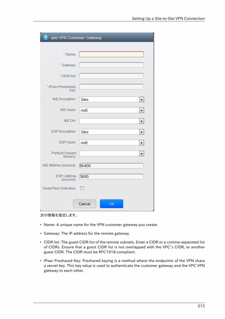
Setting Up a Site-to-Site VPN Connection
213
次の情報を指定します。
• Name: A unique name for the VPN customer gateway you create.
• Gateway: The IP address for the remote gateway.
• CIDR list: The guest CIDR list of the remote subnets. Enter a CIDR or a comma-separated listof CIDRs. Ensure that a guest CIDR list is not overlapped with the VPC’s CIDR, or anotherguest CIDR. The CIDR must be RFC1918-compliant.
• IPsec Preshared Key: Preshared keying is a method where the endpoints of the VPN sharea secret key. This key value is used to authenticate the customer gateway and the VPC VPNgateway to each other.
第19章 ネットワークとトラフィックの管理
214
注記The IKE peers (VPN end points) authenticate each other by computing andsending a keyed hash of data that includes the Preshared key. If the receivingpeer is able to create the same hash independently by using its Presharedkey, it knows that both peers must share the same secret, thus authenticatingthe customer gateway.
• IKE Encryption: The Internet Key Exchange (IKE) policy for phase-1. The supportedencryption algorithms are AES128, AES192, AES256, and 3DES. Authentication isaccomplished through the Preshared Keys.
注記The phase-1 is the first phase in the IKE process. In this initial negotiationphase, the two VPN endpoints agree on the methods to be used to providesecurity for the underlying IP traffic. The phase-1 authenticates the twoVPN gateways to each other, by confirming that the remote gateway has amatching Preshared Key.
• IKE Hash: The IKE hash for phase-1. The supported hash algorithms are SHA1 and MD5.
• IKE DH: A public-key cryptography protocol which allows two parties to establish a sharedsecret over an insecure communications channel. The 1536-bit Diffie-Hellman group is usedwithin IKE to establish session keys. The supported options are None, Group-5 (1536-bit)and Group-2 (1024-bit).
• ESP Encryption: Encapsulating Security Payload (ESP) algorithm within phase-2. Thesupported encryption algorithms are AES128, AES192, AES256, and 3DES.
注記The phase-2 is the second phase in the IKE process. The purpose of IKEphase-2 is to negotiate IPSec security associations (SA) to set up the IPSectunnel. In phase-2, new keying material is extracted from the Diffie-Hellmankey exchange in phase-1, to provide session keys to use in protecting theVPN data flow.
• ESP Hash: Encapsulating Security Payload (ESP) hash for phase-2. Supported hashalgorithms are SHA1 and MD5.
• Perfect Forward Secrecy: Perfect Forward Secrecy (or PFS) is the property that ensures that asession key derived from a set of long-term public and private keys will not be compromised.This property enforces a new Diffie-Hellman key exchange. It provides the keying materialthat has greater key material life and thereby greater resistance to cryptographic attacks. Theavailable options are None, Group-5 (1536-bit) and Group-2 (1024-bit). The security of thekey exchanges increase as the DH groups grow larger, as does the time of the exchanges.
Setting Up a Site-to-Site VPN Connection
215
注記When PFS is turned on, for every negotiation of a new phase-2 SA the twogateways must generate a new set of phase-1 keys. This adds an extra layer ofprotection that PFS adds, which ensures if the phase-2 SA’s have expired, thekeys used for new phase-2 SA’s have not been generated from the currentphase-1 keying material.
• IKE Lifetime (seconds): The phase-1 lifetime of the security association in seconds. Default is86400 seconds (1 day). Whenever the time expires, a new phase-1 exchange is performed.
• ESP Lifetime (seconds): The phase-2 lifetime of the security association in seconds. Defaultis 3600 seconds (1 hour). Whenever the value is exceeded, a re-key is initiated to provide anew IPsec encryption and authentication session keys.
• Dead Peer Detection: A method to detect an unavailable Internet Key Exchange (IKE) peer.Select this option if you want the virtual router to query the liveliness of its IKE peer at regularintervals. It’s recommended to have the same configuration of DPD on both side of VPNconnection.
5. 「OK」をクリックします。
Updating and Removing a VPN Customer GatewayYou can update a customer gateway either with no VPN connection, or related VPN connectionis in error state.
1. 管理者もしくはエンドユーザーとして CloudStack UI にログインします。
2. 左側のナビゲーションから [Network] を選択します。
3. In the Select view, select VPN Customer Gateway.
4. Select the VPN customer gateway you want to work with.
5.To modify the required parameters, click the Edit VPN Customer Gateway button
6.To remove the VPN customer gateway, click the Delete VPN Customer Gateway button
7. 「OK」をクリックします。
19.17.4.2. VPC での VPN ゲートウェイの作成1. 管理者もしくはエンドユーザーとして CloudStack UI にログインします。
2. 左側のナビゲーションから [Network] を選択します。
3. 選択ビューから VPC を選択します。
アカウントに対して作成された全ての VPC がページにリスト表示されます。
4. 仮想マシンを展開したい VPC の [Configure] ボタンをクリックします。
第19章 ネットワークとトラフィックの管理
216
VPC ページではダイアグラム上にリストされる作成された全ての層が表示されます。
5. 設定アイコンをクリックします。
以下のオプションが表示されます。
• IP アドレス
• ゲートウェイ
• サイト間 VPN
• ネットワーク ACL
6. サイト間 VPN を選択します。
既に VPN ゲートウェイを作成している場合は表示された VPN ゲートウェイからサイト間 VPN を選択します。
7. 確認ダイアログで [Yes] を選択します。
しばらく経つと VPN ゲートウェイが作成されます。その後、作成したVPN ゲートウェイの詳細が表示されます。次に [Yes] をクリックします。
VPN ゲートウェイ情報ページでは以下の詳細情報が表示されます。
• IP アドレス
• アカウント
• ドメイン
19.17.4.3. VPC 接続の作成1. 管理者もしくはエンドユーザーとして CloudStack UI にログインします。
2. 左側のナビゲーションから [Network] を選択します。
3. 選択ビューから VPC を選択します。
アカウントに対し作成した全ての VPC がページに表示されます。
4. 仮想マシンを展開したい VPC の [Configure] ボタンをクリックします。
VPC ページではダイアグラム上にリストされる作成された全ての層が表示されます。
5. 設定アイコンをクリックします。
以下のオプションが表示されます。
• IP アドレス
• ゲートウェイ
• サイト間 VPN
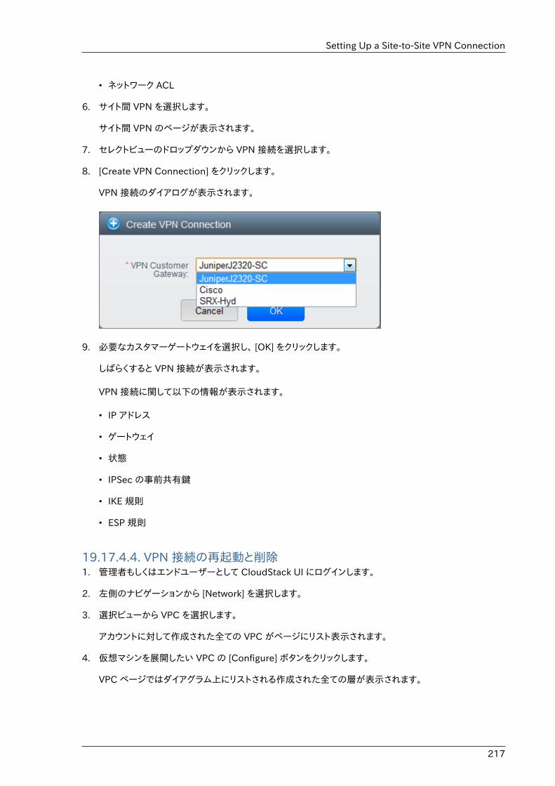
Setting Up a Site-to-Site VPN Connection
217
• ネットワーク ACL
6. サイト間 VPN を選択します。
サイト間 VPN のページが表示されます。
7. セレクトビューのドロップダウンから VPN 接続を選択します。
8. [Create VPN Connection] をクリックします。
VPN 接続のダイアログが表示されます。
9. 必要なカスタマーゲートウェイを選択し、 [OK] をクリックします。
しばらくすると VPN 接続が表示されます。
VPN 接続に関して以下の情報が表示されます。
• IP アドレス
• ゲートウェイ
• 状態
• IPSec の事前共有鍵
• IKE 規則
• ESP 規則
19.17.4.4. VPN 接続の再起動と削除1. 管理者もしくはエンドユーザーとして CloudStack UI にログインします。
2. 左側のナビゲーションから [Network] を選択します。
3. 選択ビューから VPC を選択します。
アカウントに対して作成された全ての VPC がページにリスト表示されます。
4. 仮想マシンを展開したい VPC の [Configure] ボタンをクリックします。
VPC ページではダイアグラム上にリストされる作成された全ての層が表示されます。
第19章 ネットワークとトラフィックの管理
218
5. 設定アイコンをクリックします。
以下のオプションが表示されます。
• IP アドレス
• ゲートウェイ
• サイト間 VPN
• ネットワーク ACL
6. サイト間 VPN を選択します。
サイト間 VPN のページが表示されます。
7. セレクトビューのドロップダウンから VPN 接続を選択します。
作成した全ての VPN 接続が表示されます。
8. 対象となる VPN 接続を選択します。
[詳細] タブが表示されます。
9.VPN 接続を削除するには [Delete VPN Connection] ボタンをクリックします。
VPN 接続を再起動するには [詳細] タブにある [Reset VPN Connection] ボタンをクリックします。
19.18. About Inter-VLAN RoutingInter-VLAN Routing is the capability to route network traffic between VLANs. This feature enablesyou to build Virtual Private Clouds (VPC), an isolated segment of your cloud, that can hold multi-tierapplications. These tiers are deployed on different VLANs that can communicate with each other.You provision VLANs to the tiers your create, and VMs can be deployed on different tiers. The VLANsare connected to a virtual router, which facilitates communication between the VMs. In effect, youcan segment VMs by means of VLANs into different networks that can host multi-tier applications,such as Web, Application, or Database. Such segmentation by means of VLANs logically separateapplication VMs for higher security and lower broadcasts, while remaining physically connectedto the same device.
This feature is supported on XenServer and VMware hypervisors.
The major advantages are:
• The administrator can deploy a set of VLANs and allow users to deploy VMs on these VLANs. Aguest VLAN is randomly alloted to an account from a pre-specified set of guest VLANs. All theVMs of a certain tier of an account reside on the guest VLAN allotted to that account.
注記A VLAN allocated for an account cannot be shared between multiple accounts.
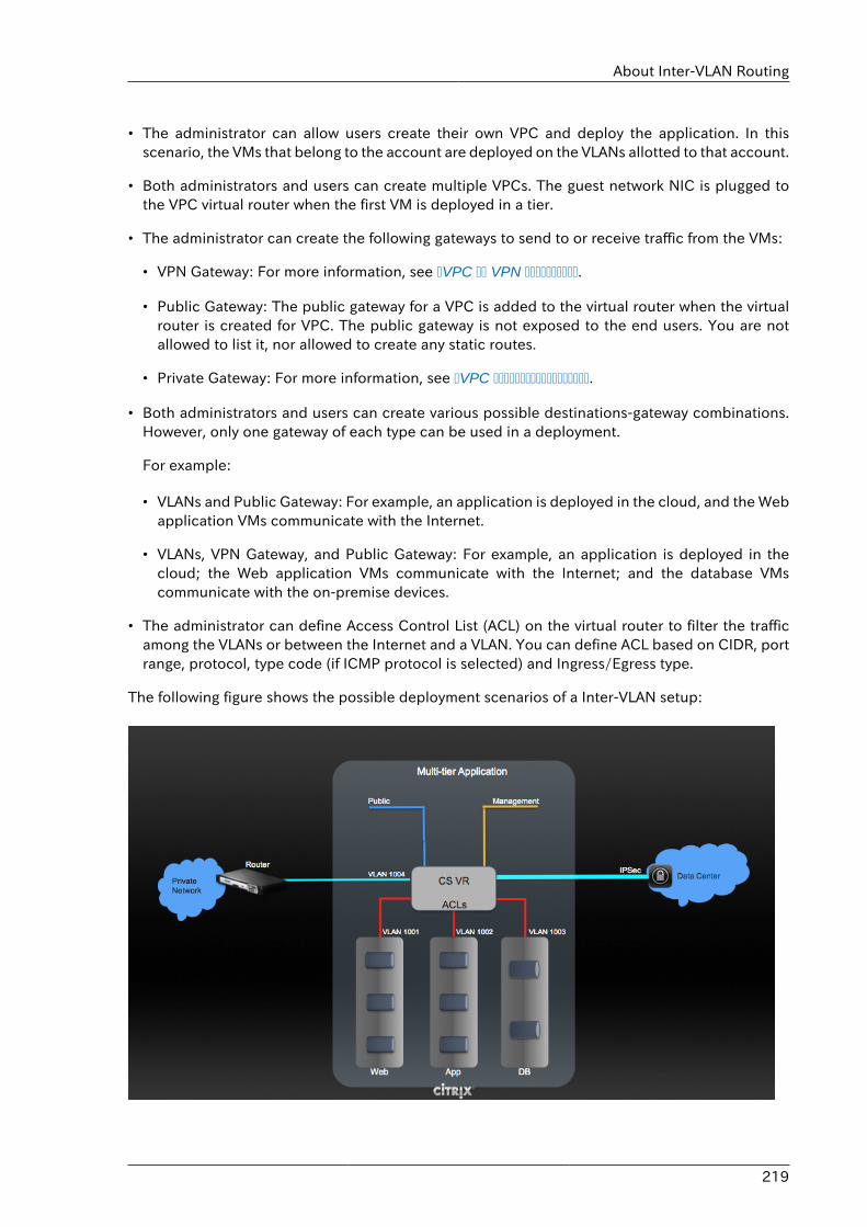
About Inter-VLAN Routing
219
• The administrator can allow users create their own VPC and deploy the application. In thisscenario, the VMs that belong to the account are deployed on the VLANs allotted to that account.
• Both administrators and users can create multiple VPCs. The guest network NIC is plugged tothe VPC virtual router when the first VM is deployed in a tier.
• The administrator can create the following gateways to send to or receive traffic from the VMs:
• VPN Gateway: For more information, see �VPC �� VPN ����������.
• Public Gateway: The public gateway for a VPC is added to the virtual router when the virtualrouter is created for VPC. The public gateway is not exposed to the end users. You are notallowed to list it, nor allowed to create any static routes.
• Private Gateway: For more information, see �VPC ������������������.
• Both administrators and users can create various possible destinations-gateway combinations.However, only one gateway of each type can be used in a deployment.
For example:
• VLANs and Public Gateway: For example, an application is deployed in the cloud, and the Webapplication VMs communicate with the Internet.
• VLANs, VPN Gateway, and Public Gateway: For example, an application is deployed in thecloud; the Web application VMs communicate with the Internet; and the database VMscommunicate with the on-premise devices.
• The administrator can define Access Control List (ACL) on the virtual router to filter the trafficamong the VLANs or between the Internet and a VLAN. You can define ACL based on CIDR, portrange, protocol, type code (if ICMP protocol is selected) and Ingress/Egress type.
The following figure shows the possible deployment scenarios of a Inter-VLAN setup:
第19章 ネットワークとトラフィックの管理
220
To set up a multi-tier Inter-VLAN deployment, see �VPC ����.
19.19. VPC の構成
19.19.1. VPC(Virtual Private Cloud) の概要CloudStack 仮想プライベートクラウドは CloudStack の機能の一部です。 VPC は一般的な物理ネットワークに似た独自の仮想ネットワークトポロジを持ち、ユーザーはプライベードアドレスを持つ仮想マシンをその仮想ネットワーク上で起動することができます。例: 10.0.0.0/16。 IP のアドレス範囲に準じた仮想マシングループに対し VPC のネットワークを有効化し、層を定義することができます。
例として、VPC がプライベートなアドレス範囲である 10.0.0.0/16 を持っていした場合、ゲストネットワークは10.0.1.0/24, 10.0.2.0/24, 10.0.3.0/24 といったアドレスを持つことができます。
VPC の主要コンポーネント。VPC は以下のネットワークコンポーネントから構成されます。
• VPC: VPC は仮想ルーターを介し通信することができる、複数の独立したネットワークのコンテナとして動作します。
• Network Tiers: 各層はそれぞれ独立したネットワークとして VLAN 情報やCIDR情報を持ち、VLAN によってセグメント化されます。各層の NIC はゲートウェイとして動作します。
• Virtual Router: 仮想ルーターは自動的に作成され VPC 作成とともに起動します。仮想ルーターは各層とパブリックなゲートウェイから受信する直接のトラフィック、VPN ゲートウェイ、NAT インスタンスに接しています。各層は NIC や 仮想ルーターの IP と連携しDNS や DHCP といったサービスを提供します。
• Public Gateway: インターネットと VPC との通信はパブリックゲートウェイを介して処理されます。VPC ではパブリックゲートウェイはエンドユーザーに対し不可視であるため静的ルーティングはパブリックゲートウェイではサポートされていません。
• Private Gateway: プライベートネットワークと VPC との通信は全てルーティングされます。詳細な情報は�VPC ������������������ を参照して下さい。
• VPN Gateway: VPC に付与される VPN 接続です。
• Site-to-Site VPN Connection: VPC とデータセンターやホームネットワーク、コロケーション環境とを接続するハードウェアベースの VPN 接続です。詳細な情報は �Setting Up a Site-to-Site VPN Connection� を参照して下さい。
• Customer Gateway: VPN 接続の利用者側ゲートウェイです。詳細な情報は �Creating and Updating aVPN Customer Gateway� を参照して下さい。
• NAT Instance: インターネットからパブリックゲートウェイを介しての仮想マシンアクセスのためのポートアドレス転送を提供するインスタンスです。詳細な情報は �VPC ���� NAT ��������� を参照して下さい。
VPC のネットワークアーキテクチャVPC では次のネットワークアーキテクチャの基本的なオプションが提供されます。
• パブリックゲートウェイのみの VPC
VPC(Virtual Private Cloud) の概要
221
• パブリック、プライベートゲートウェイを持つ VPC
• パブリック、プライベートゲートウェイとサイト間 VPN アクセスを持つ VPC
• プライベートゲートウェイのみとサイト間 VPN アクセスを持つ VPC
VPC の接続オプション次のように VPC に接続することができます。
• パブリックゲートウェイを介してインターネットから接続。
• VPN ゲートウェイを介しサイト間 VPN 接続を利用して会社のデータセンターから接続
• パブリックゲートウェイと VPN ゲートウェイを利用してインターネット、会社のデータセンター双方から接続
VPC ネットワークの考慮点VPC を作成する前に次のことを考慮しておきます。
• VPC はデフォルトで作成された際に有効化されます。
• A VPC can be created in Advance zone only, and can't belong to more than one zone at a time.
• デフォルトの VPC の作成可能数はアカウント毎に20個です。しかし、グローバル設定の max.account.vpcsを変更することでアカウント毎に作成可能な VPC の最大数を制御することができます。
• デフォルトの VPC 上の層の作成可能数はアカウント毎に3個です。vpc.max.networks を変更することで最大数を制御することができます。
• Each tier should have an unique CIDR in the VPC. Ensure that the tier's CIDR should be withinthe VPC CIDR range.
• 層は単一の VPC にのみ所属します。
• VPC 内の全てのネットワーク層は同一アカウントに紐付けられるべきです。
• デフォルトでは VPC が作成された際、送信元 NAT 用 IP が割り当てられます。送信元 NAT 用 IP は VPCが削除された時のみ開放されます。
• パブリック IP は同時に1つだけ利用することができます。IP が送信元 NAT 用である場合静的 NAT や ポート転送用に割り当てることはできません。
• 展開された仮想マシンはプライベート IP のみ利用することができます。インターネットへの通信を行う場合、展開した VPC で仮想マシンに対しての NAT を有効化する必要があります。
• 新しいネットワークのみが VPC に対して追加できます。VPC 毎のネットワークの最大値はvpc.max.networks によって制限されており、デフォルト値は3です。
• 負荷分散サービスは VPC 内の単一の層に対してのみサポートされます。
• 層に IP アドレスが割り当てられた場合
• That IP can't be used by more than one tier at a time in the VPC. For example, if you have tiersA and B, and a public IP1, you can create a port forwarding rule by using the IP either for Aor B, but not for both.
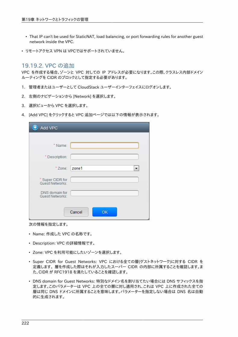
第19章 ネットワークとトラフィックの管理
222
• That IP can't be used for StaticNAT, load balancing, or port forwarding rules for another guestnetwork inside the VPC.
• リモートアクセス VPN は VPCではサポートされていません。
19.19.2. VPC の追加VPC を作成する場合、ゾーンと VPC 対しての IP アドレスが必要になります。この際、クラスレス内部ドメインルーティングを CIDR のブロックとして指定する必要があります。
1. 管理者またはユーザーとして CloudStack ユーザーインターフェイスにログオンします。
2. 左側のナビゲーションから [Network] を選択します。
3. 選択ビューから VPC を選択します。
4. [Add VPC] をクリックすると VPC 追加ページでは以下の情報が表示されます。
次の情報を指定します。
• Name: 作成した VPC の名称です。
• Description: VPC の詳細情報です。
• Zone: VPC を利用可能にしたいゾーンを選択します。
• Super CIDR for Guest Networks: VPC における全ての層(ゲストネットワーク)に対する CIDR を定義します。 層を作成した際はそれが入力したスーパー CIDR の内部に所属することを確認します。また、CIDR が RFC1918 を満たしていることを確認します。
• DNS domain for Guest Networks: 特別なドメイン名を割り当てたい場合には DNS サフィックスを指定します。このパラメーターは VPC 上の全ての層に対し適用され、これは VPC 上に作成された全ての層は同じ DNS ドメインに所属することを意味します。パラメーターを指定しない場合は DNS 名は自動的に生成されます。
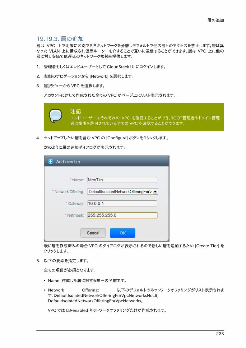
層の追加
223
19.19.3. 層の追加層は VPC 上で明確に区別でき各ネットワークを分離しデフォルトで他の層とのアクセスを禁止します。層は異なった VLAN 上に構成され仮想ルーターを介することで互いに通信することができます。層は VPC 上に他の層に対し安価で低遅延のネットワーク接続を提供します。
1. 管理者もしくはエンドユーザーとして CloudStack UI にログインします。
2. 左側のナビゲーションから [Network] を選択します。
3. 選択ビューから VPC を選択します。
アカウントに対して作成された全ての VPC がページ上にリスト表示されます。
注記エンドユーザーはそれぞれの VPC を確認することができ、ROOT管理者やドメイン管理者は権限を許可されている全ての VPC を確認することができます。
4. セットアップしたい層を含む VPC の [Configure] ボタンをクリックします。
次のように層の追加ダイアログが表示されます。
既に層を作成済みの場合 VPC のダイアログが表示されるので新しい層を追加するため [Create Tier] をクリックします。
5. 以下の要素を指定します。
全ての項目が必須となります。
• Name: 作成した層に対する唯一の名前です。
• Network Offering: 以下のデフォルトのネットワークオファリングがリスト表示されます。DefaultIsolatedNetworkOfferingForVpcNetworksNoLB,DefaultIsolatedNetworkOfferingForVpcNetworks。
VPC では LB-enabled ネットワークオファリングだけが作成されます。
第19章 ネットワークとトラフィックの管理
224
• Gateway: 作成された層のゲートウェイです。VPC 作成時に指定したスーパー CIDR 内に収まり、VPC内の他の層と重複しないことを確認します。
• Netmask: 作成された層のネットマスクです。
例として、もし VPC の CIDR を10.0.0.0/16とした場合、層の CIDR は10.0.1.0/24となり、ゲートウェイは10.0.1.1 となります。またその際のネットマスクは255.255.255.0となります。
6. 「OK」をクリックします。
7. 層のアクセス制御リストを設定する場合は引き続き設定を続けます。
19.19.4. Configuring Access Control ListDefine Network Access Control List (ACL) on the VPC virtual router to control incoming (ingress)and outgoing (egress) traffic between the VPC tiers, and the tiers and Internet. By default, allincoming and outgoing traffic to the guest networks is blocked. To open the ports, you must createa new network ACL. The network ACLs can be created for the tiers only if the NetworkACL serviceis supported.
1. 管理者またはユーザーとして CloudStack ユーザーインターフェイスにログオンします。
2. 左側のナビゲーションから [Network] を選択します。
3. 選択ビューから VPC を選択します。
アカウントに対して作成された全ての VPC がページにリスト表示されます。
4. 設定アイコンをクリックします。
以下のオプションが表示されます。
• IP アドレス
• ゲートウェイ
• サイト間 VPN
• ネットワーク ACL
5. Select Network ACLs.
The Network ACLs page is displayed.
6. Click Add Network ACLs.
To add an ACL rule, fill in the following fields to specify what kind of network traffic is allowedin this tier.
• CIDR: The CIDR acts as the Source CIDR for the Ingress rules, and Destination CIDR for theEgress rules. To accept traffic only from or to the IP addresses within a particular addressblock, enter a CIDR or a comma-separated list of CIDRs. The CIDR is the base IP address ofthe incoming traffic. For example, 192.168.0.0/22. To allow all CIDRs, set to 0.0.0.0/0.
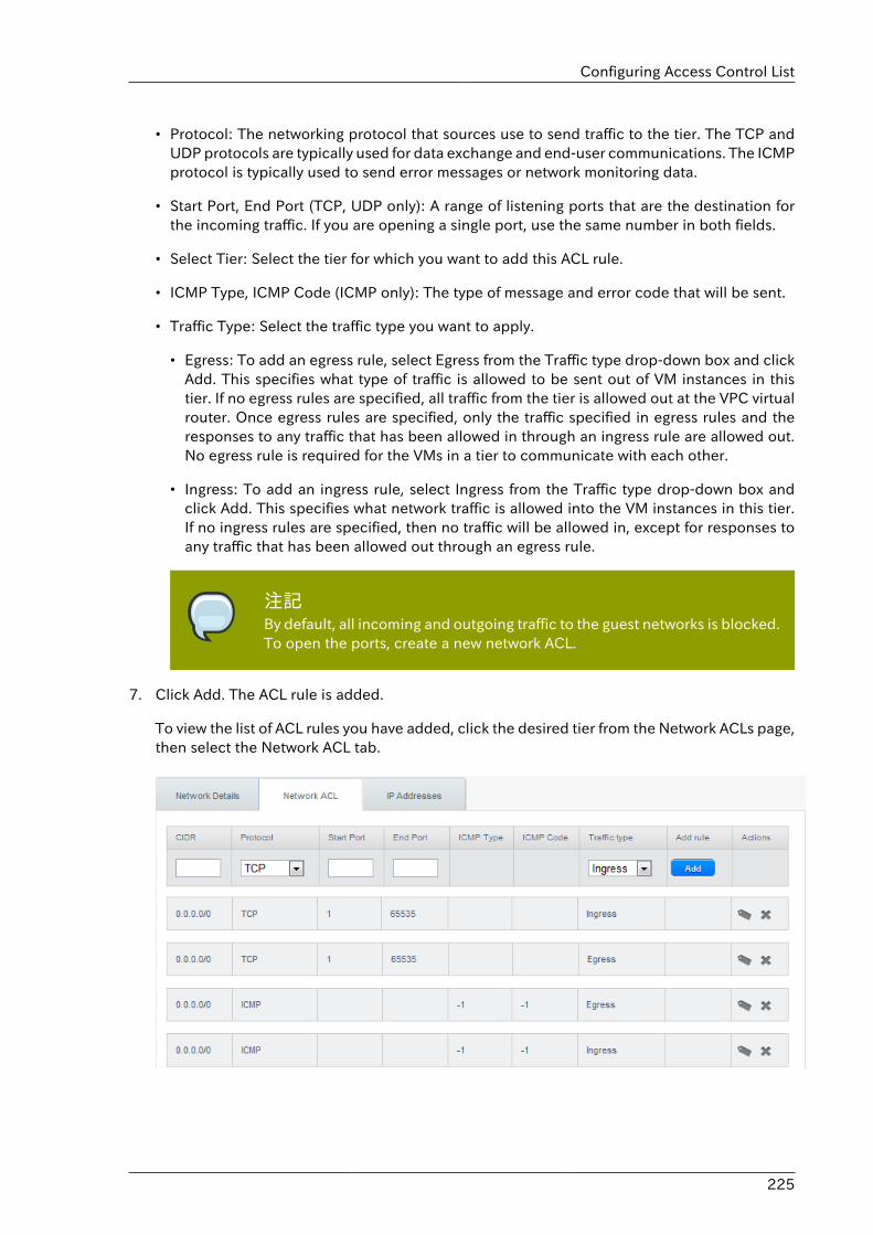
Configuring Access Control List
225
• Protocol: The networking protocol that sources use to send traffic to the tier. The TCP andUDP protocols are typically used for data exchange and end-user communications. The ICMPprotocol is typically used to send error messages or network monitoring data.
• Start Port, End Port (TCP, UDP only): A range of listening ports that are the destination forthe incoming traffic. If you are opening a single port, use the same number in both fields.
• Select Tier: Select the tier for which you want to add this ACL rule.
• ICMP Type, ICMP Code (ICMP only): The type of message and error code that will be sent.
• Traffic Type: Select the traffic type you want to apply.
• Egress: To add an egress rule, select Egress from the Traffic type drop-down box and clickAdd. This specifies what type of traffic is allowed to be sent out of VM instances in thistier. If no egress rules are specified, all traffic from the tier is allowed out at the VPC virtualrouter. Once egress rules are specified, only the traffic specified in egress rules and theresponses to any traffic that has been allowed in through an ingress rule are allowed out.No egress rule is required for the VMs in a tier to communicate with each other.
• Ingress: To add an ingress rule, select Ingress from the Traffic type drop-down box andclick Add. This specifies what network traffic is allowed into the VM instances in this tier.If no ingress rules are specified, then no traffic will be allowed in, except for responses toany traffic that has been allowed out through an egress rule.
注記By default, all incoming and outgoing traffic to the guest networks is blocked.To open the ports, create a new network ACL.
7. Click Add. The ACL rule is added.
To view the list of ACL rules you have added, click the desired tier from the Network ACLs page,then select the Network ACL tab.
第19章 ネットワークとトラフィックの管理
226
You can edit the tags assigned to the ACL rules and delete the ACL rules you have created.Click the appropriate button in the Actions column.
19.19.5. VPC へのプライベートゲートウェイの追加プライベートゲートウェイはルート管理者のみ追加することができます。VPCのプライベートネットワークは物理ネットワークの NIC と1対1の関係があり、同一データセンター上でゲートウェイを持たない重複しない VLANや IP が許容されます。
1. 管理者もしくはエンドユーザーとして CloudStack UI にログインします。
2. 左側のナビゲーションから [Network] を選択します。
3. 選択ビューから VPC を選択します。
アカウントに対して作成された全ての VPC がページにリスト表示されます。
4. 負荷分散ルールを構成したい VPC の構成ボタンをクリックします。
VPC ページではダイアグラム上にリストされる作成された全ての層が表示されます。
5. 設定アイコンをクリックします。
以下のオプションが表示されます。
• IP アドレス
• プライベートゲートウェイ
• サイト間 VPN
• ネットワーク ACL
6. プライベートゲートウェイを選択します。
ゲートウェイのページに表示されます。
7. [Add new gateway]をクリックします。
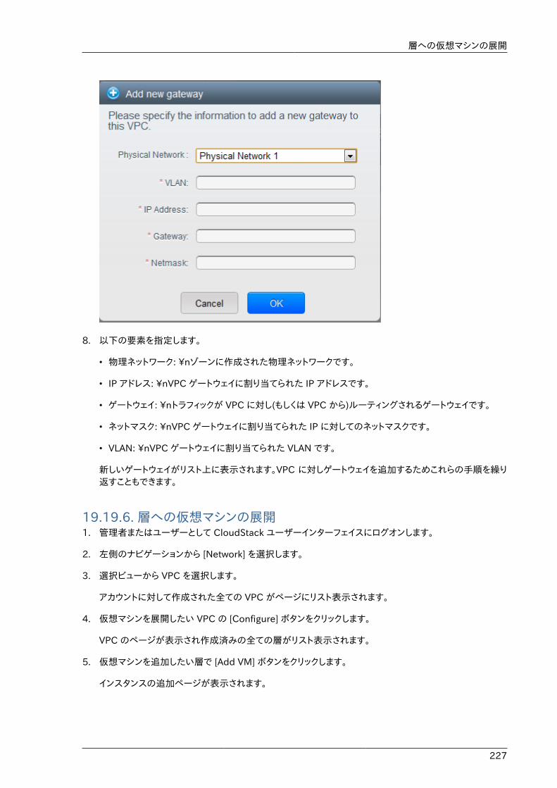
層への仮想マシンの展開
227
8. 以下の要素を指定します。
• 物理ネットワーク: \nゾーンに作成された物理ネットワークです。
• IP アドレス: \nVPC ゲートウェイに割り当てられた IP アドレスです。
• ゲートウェイ: \nトラフィックが VPC に対し(もしくは VPC から)ルーティングされるゲートウェイです。
• ネットマスク: \nVPC ゲートウェイに割り当てられた IP に対してのネットマスクです。
• VLAN: \nVPC ゲートウェイに割り当てられた VLAN です。
新しいゲートウェイがリスト上に表示されます。VPC に対しゲートウェイを追加するためこれらの手順を繰り返すこともできます。
19.19.6. 層への仮想マシンの展開1. 管理者またはユーザーとして CloudStack ユーザーインターフェイスにログオンします。
2. 左側のナビゲーションから [Network] を選択します。
3. 選択ビューから VPC を選択します。
アカウントに対して作成された全ての VPC がページにリスト表示されます。
4. 仮想マシンを展開したい VPC の [Configure] ボタンをクリックします。
VPC のページが表示され作成済みの全ての層がリスト表示されます。
5. 仮想マシンを追加したい層で [Add VM] ボタンをクリックします。
インスタンスの追加ページが表示されます。
第19章 ネットワークとトラフィックの管理
228
この場面でインスタンスを追加するにはページの指示に従います。インスタンスの追加に関してはインストールガイドの「インスタンスの追加」の章を参照して下さい。
19.19.7. VPC に対しての新しい IP アドレスの取得When you acquire an IP address, all IP addresses are allocated to VPC, not to the guest networkswithin the VPC. The IPs are associated to the guest network only when the first port-forwarding,load balancing, or Static NAT rule is created for the IP or the network. IP can't be associated tomore than one network at a time.
1. 管理者またはユーザーとして CloudStack ユーザーインターフェイスにログオンします。
2. 左側のナビゲーションから [Network] を選択します。
3. 選択ビューから [VPC] を選択します。
アカウントに対して作成された全ての VPC がページにリスト表示されます。
4. 仮想マシンを展開したい VPC の [Configure] ボタンをクリックします。
VPC ページではダイアグラム上にリストされる作成された全ての層が表示されます。
5. 設定アイコンをクリックします。
以下のオプションが表示されます。
• IP アドレス
• ゲートウェイ
• サイト間 VPN
• ネットワーク ACL
6. IP アドレスを選択します。
IP アドレスのページが表示されます。
7. [Acquire New IP] をクリックし、確認ダイアログで [Yes] をクリックします。
一般的に IP アドレスは限りあるリソースであるため確認用ページが表示されます。しばらく経つと状態が[Allocated] に変化し新しい IP アドレスが表示されます。これでポート転送や負荷分散、静的NATルールに対し IP アドレスを利用することができます。
19.19.8. VPC に割り当てられた IP アドレスの開放IP アドレスは限られたリソースであり、特定の IP をこれ以上利用することが無い場合は VPC から IP を開放し利用可能アドレスのプールに返却することができます。IP アドレスに対し全てのネットワーク機能(ポート転送、負荷分散、静的NATルール)を削除している場合には層から IP アドレスを開放することができます。ここで開放された IP アドレスは同一の VPC に属し続けます。
1. 管理者またはユーザーとして CloudStack ユーザーインターフェイスにログオンします。
2. 左側のナビゲーションから [Network] を選択します。
VPC での静的 NAT の有効化、無効化
229
3. 選択ビューから VPC を選択します。
アカウントに対して作成された全ての VPC がページにリスト表示されます。
4. 開放したい IP を持つ VPC の [Configure] ボタンをクリックします。
VPC ページではダイアグラム上にリストされる作成された全ての層が表示されます。
5. 設定アイコンをクリックします。
以下のオプションが表示されます。
• IP アドレス
• ゲートウェイ
• サイト間 VPN
• ネットワーク ACL
6. IP アドレスを選択します。
IP アドレスのページが表示されます。
7. 開放したい IP をクリックします。
8.詳細タブで [Release IP] ボタンをクリックします。
19.19.9. VPC での静的 NAT の有効化、無効化静的 NAT ルールは VPC 内の仮想マシンに割り当てられたプライベート IP に対しインターネットからのトラフィックを渡すためパブリック IP と関連付けられます。この章では VPC 上の特定 IP アドレスに対してどのように静的 NAT の有効化、無効化するか説明しています。
もし、すでにポートフォワーディングのルールが IP アドレスに反映されている場合、IP に対して静的 NAT を有効化することができません。
仮想マシンがいくつかのネットワークに所属している場合、静的 NAT のルールは デフォルトネットワークでしか機能しません。
1. 管理者またはユーザーとして CloudStack ユーザーインターフェイスにログオンします。
2. 左側のナビゲーションから [Network] を選択します。
3. 選択ビューから VPC を選択します。
アカウントに対して作成された全ての VPC がページにリスト表示されます。
4. 仮想マシンを展開したい VPC の [Configure] ボタンをクリックします。
VPC ページではダイアグラム上にリストされる作成された全ての層が表示されます。
5. 設定アイコンをクリックします。
以下のオプションが表示されます。
• IP アドレス
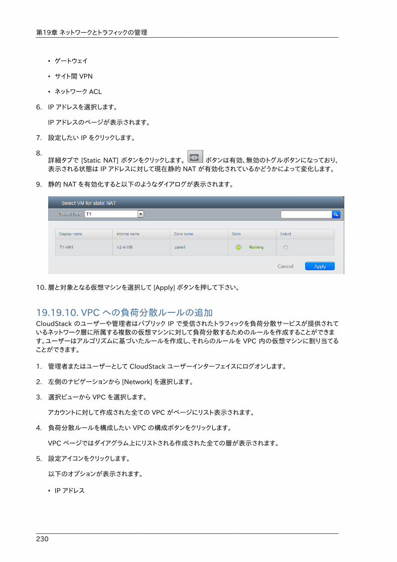
第19章 ネットワークとトラフィックの管理
230
• ゲートウェイ
• サイト間 VPN
• ネットワーク ACL
6. IP アドレスを選択します。
IP アドレスのページが表示されます。
7. 設定したい IP をクリックします。
8.詳細タブで [Static NAT] ボタンをクリックします。 ボタンは有効、無効のトグルボタンになっており、表示される状態は IP アドレスに対して現在静的 NAT が有効化されているかどうかによって変化します。
9. 静的 NAT を有効化すると以下のようなダイアログが表示されます。
10. 層と対象となる仮想マシンを選択して [Apply] ボタンを押して下さい。
19.19.10. VPC への負荷分散ルールの追加CloudStack のユーザーや管理者はパブリック IP で受信されたトラフィックを負荷分散サービスが提供されているネットワーク層に所属する複数の仮想マシンに対して負荷分散するためのルールを作成することができます。ユーザーはアルゴリズムに基づいたルールを作成し、それらのルールを VPC 内の仮想マシンに割り当てることができます。
1. 管理者またはユーザーとして CloudStack ユーザーインターフェイスにログオンします。
2. 左側のナビゲーションから [Network] を選択します。
3. 選択ビューから VPC を選択します。
アカウントに対して作成された全ての VPC がページにリスト表示されます。
4. 負荷分散ルールを構成したい VPC の構成ボタンをクリックします。
VPC ページではダイアグラム上にリストされる作成された全ての層が表示されます。
5. 設定アイコンをクリックします。
以下のオプションが表示されます。
• IP アドレス
VPC へのポート転送ルールの追加
231
• ゲートウェイ
• サイト間 VPN
• ネットワーク ACL
6. IP アドレスを選択します。
IP アドレスのページが表示されます。
7. ルールを作成したい IP アドレスをクリックし、[Configuration] タブをクリックします。
8. 構成図のロードバランサーをクリックし、[View All] をクリックします。
9. ルールを適用したい層を選択します。
注記VPC 内では単一の層に対して負荷分散サービスがサポートされます。
10. 以下の要素を指定します。
• Name : 負荷分散ルールの名前です。
• Public Port: 負荷分散用に受信されるトラッフィク用ポート
• Private Port : 仮想マシンがトラフィックを受信するポート番号です。
• Algorighm\nCloudStack で利用したい負荷分散アルゴリズムを選択します。以下のアルゴリズムがサポートされます。
• ラウンドロビン
• 直近での接続
• 接続元
• Stickness. (オプション) Click Configure and choose the algorithm for the stickiness policy. SeeSticky Session Policies for Load Balancer Rules.\n[Configure] をクリックし、スティックネス規則用のアルゴリズムを選択します。負荷分散ルール用スティッキーセッション規則を参照して下さい。
• Add VMs: Click Add VMs, then select two or more VMs that will divide the load of incomingtraffic, and click Apply.\n[Add VMs] をクリックし受信トラフィックを負荷分散したい2つ以上の仮想マシンを選択します。その後、[Apply] をクリックします。
新しい負荷分散ルールがリスト表示され、さらに IP アドレスに対しての負荷分散ルールを追加することができます。
19.19.11. VPC へのポート転送ルールの追加1. 管理者またはユーザーとして CloudStack ユーザーインターフェイスにログオンします。
2. 左側のナビゲーションから [Network] を選択します。
第19章 ネットワークとトラフィックの管理
232
3. 選択ビューから VPC を選択します。
アカウントに対して作成された全ての VPC がページにリスト表示されます。
4. 仮想マシンを展開したい VPC の [Configure] ボタンをクリックします。
VPC ページではダイアグラム上にリストされる作成された全ての層が表示されます。
5. 設定アイコンをクリックします。
以下のオプションが表示されます。
• IP アドレス
• ゲートウェイ
• サイト間 VPN
• ネットワーク ACL
6. 既存の IP アドレスを選択するか新しい IP アドレスを取得します。リスト表示された IP アドレス名をクリックします。
IP アドレスのページが表示されます。
7. ルールを作成したい IP アドレスをクリックし、[Configuration] タブをクリックします。
8. ダイアグラムの[Port Forwarding]ノードの[View All]をクリックします。
9. ルールを適用したい層を選択します。
10. 以下の要素を指定します。
• Public Port: The port to which public traffic will be addressed on the IP address you acquiredin the previous step.以前の手順で取得したどの IP アドレスへのパブリックトラフィックを受信するポートを指定します。
• Private Port: 仮想マシンが転送されたパブリックトラッフィクをリッスンするポートを指定します。
• Protocol: それぞれのポートで利用する通信プロトコルを指定します。
• TCP
• UDP
• Add VM: [Add VM] をクリックします。その後、ルールを適用したい仮想マシン名を選択し [Apply] をクリックします。
仮想マシンへの ssh セッションを作成することでルールをテストすることができます。
19.19.12. 層の削除VPC から層を削除することができ、削除された層は無効化することができません。層を削除した場合、層に設定したリソースのみ削除されます。全てのネットワークルール(ポート転送や負荷分散、静的 NAT など)と IP アドレスは削除された層に割り当てられたままになります。その際、IP アドレスは VPC に所属し続けます。
1. 管理者またはユーザーとして CloudStack ユーザーインターフェイスにログオンします。
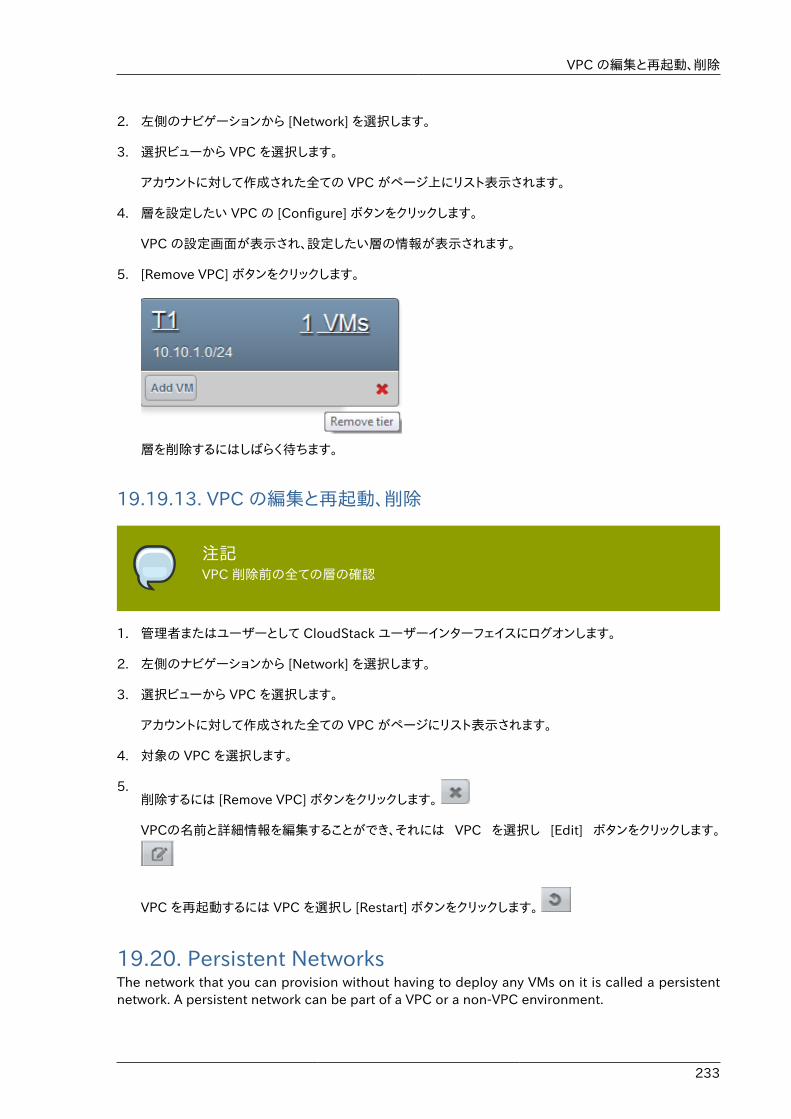
VPC の編集と再起動、削除
233
2. 左側のナビゲーションから [Network] を選択します。
3. 選択ビューから VPC を選択します。
アカウントに対して作成された全ての VPC がページ上にリスト表示されます。
4. 層を設定したい VPC の [Configure] ボタンをクリックします。
VPC の設定画面が表示され、設定したい層の情報が表示されます。
5. [Remove VPC] ボタンをクリックします。
層を削除するにはしばらく待ちます。
19.19.13. VPC の編集と再起動、削除
注記VPC 削除前の全ての層の確認
1. 管理者またはユーザーとして CloudStack ユーザーインターフェイスにログオンします。
2. 左側のナビゲーションから [Network] を選択します。
3. 選択ビューから VPC を選択します。
アカウントに対して作成された全ての VPC がページにリスト表示されます。
4. 対象の VPC を選択します。
5.削除するには [Remove VPC] ボタンをクリックします。
VPCの名前と詳細情報を編集することができ、それには VPC を選択し [Edit] ボタンをクリックします。
VPC を再起動するには VPC を選択し [Restart] ボタンをクリックします。
19.20. Persistent NetworksThe network that you can provision without having to deploy any VMs on it is called a persistentnetwork. A persistent network can be part of a VPC or a non-VPC environment.
第19章 ネットワークとトラフィックの管理
234
When you create other types of network, a network is only a database entry until the first VM iscreated on that network. When the first VM is created, a VLAN ID is assigned and the networkis provisioned. Also, when the last VM is destroyed, the VLAN ID is released and the network isno longer available. With the addition of persistent network, you will have the ability to create anetwork in CloudStack in which physical devices can be deployed without having to run any VMs.Additionally, you can deploy physical devices on that network.
One of the advantages of having a persistent network is that you can create a VPC with a tierconsisting of only physical devices. For example, you might create a VPC for a three-tier application,deploy VMs for Web and Application tier, and use physical machines for the Database tier. Anotheruse case is that if you are providing services by using physical hardware, you can define the networkas persistent and therefore even if all its VMs are destroyed the services will not be discontinued.
19.20.1. Persistent Network Considerations• Persistent network is designed for isolated networks.
• All default network offerings are non-persistent.
• A network offering cannot be editable because changing it affects the behavior of the existingnetworks that were created using this network offering.
• When you create a guest network, the network offering that you select defines the networkpersistence. This in turn depends on whether persistent network is enabled in the selectednetwork offering.
• An existing network can be made persistent by changing its network offering to an offering thathas the Persistent option enabled. While setting this property, even if the network has no runningVMs, the network is provisioned.
• An existing network can be made non-persistent by changing its network offering to an offeringthat has the Persistent option disabled. If the network has no running VMs, during the nextnetwork garbage collection run the network is shut down.
• When the last VM on a network is destroyed, the network garbage collector checks if the networkoffering associated with the network is persistent, and shuts down the network only if it is non-persistent.
19.20.2. Creating a Persistent Guest NetworkTo create a persistent network, perform the following:
1. Create a network offering with the Persistent option enabled.
See the Administration Guide.
2. Select Network from the left navigation pane.
3. Select the guest network that you want to offer this network service to.
4. Click the Edit button.
5. From the Network Offering drop-down, select the persistent network offering you have justcreated.

Creating a Persistent Guest Network
235
6. [OK]をクリックします。

236
237
システム仮想マシンの操作CloudStack では、いくつかの種類のシステム仮想マシンを使用してクラウドでタスクを実行します。これらのシステム仮想マシンは通常、環境の規模および緊急のニーズに基づいて、CloudStack により管理、作成、起動、および停止されます。ただし、管理者はトラブルシューティングを円滑にするため、システム仮想マシンの存在とその役割を理解しておく必要があります。
注記You can configure the system.vm.random.password parameter to create a randomsystem VM password to ensure higher security. If you reset the value forsystem.vm.random.password to true and restart the Management Server, a randompassword is generated and stored encrypted in the database. You can viewthe decrypted password under the system.vm.password global parameter on theCloudStack UI or by calling the listConfigurations API.
20.1. システム仮想マシンテンプレートシステム仮想マシンは単一のテンプレートから作成されます。システム仮想マシンには、次の特性があります。
• Debian 6.0 ("Squeeze"), 2.6.32 kernel with the latest security patches from the Debian securityAPT repository
• セキュリティ上脆弱な箇所を小さくするために、最小限のパッケージがインストールされています。
• Xen/VMWare 上のパフォーマンスを向上する 32 ビット版です。
• すべてのハイパーバイザー上で最適なパフォーマンスを実現する、Xen PV ドライバー、KVM virtio ドライバー、お よび VMware Tools を備えた pvops カーネルを使用します。
• Xen Tools が含まれ、パフォーマンスを監視できます。
• Debian リポジトリから入手する最新バージョンの HAProxy、iptables、IPsec、Apache により、セキュリティ保護と速度の向上を保証します。
• Sun/Oracle の最新バージョンの JRE により、セキュリティ保護と速度の向上を保証します。
20.2. VMware のための複数のシステム仮想マシンのサポートCloudStack の各ゾーンには単一のシステム仮想マシンが存在します。この仮想マシンによって、テンプレートのダウンロードとアップロード、ISO のアップロードなどのテンプレート処理タスクが実行されます。VMware を使用するゾーンでは追加のシステム仮想マシンを起動して、スナップショットやプライベートテンプレートの作成などの VMware 特有のタスクを処理できます。負荷が増加すると、VMware 特有のタスクのためにCloudStack 管理サーバーにより追加のシステム仮想マシンが起動されます。これらのシステム仮想マシンに送信されるすべてのコマンドが管理サーバーにより監視および重み付けされ、追加のシステム仮想マシンの動的な負荷分散と拡張が実行されます。
20.3. コンソールプロキシーコンソールプロキシーはWeb UI経由でコンソールビューを表示するロールを持ったシステム仮想マシンの一種です。ユーザーのブラウザーからハイパーバイザーのVNCポート経由でゲストのコンソールに接続します。管理者とエンドユーザーのWeb UIの両方からコンソール接続が可能です。
第20章 システム仮想マシンの操作
238
Clicking a console icon brings up a new window. The AJAX code downloaded into that windowrefers to the public IP address of a console proxy VM. There is exactly one public IP addressallocated per console proxy VM. The AJAX application connects to this IP. The console proxy thenproxies the connection to the VNC port for the requested VM on the Host hosting the guest.
注記ハイパーバイザーはVNCのためにたくさんのポートを割り当てます。それにより、複数のVNCセッションを同時に行うことができます。
ゲストの仮想IPには何のトラフィックも発生しませんので、ゲスト内でVNCを有効にする必要はありません。
コンソールプロキシーVMはアクティブなセッションの数を管理サーバーに定期的にレポートします。デフォルトのレポート間隔は5分です。これは管理サーバーのグローバル設定のパラメーターのconsoleproxy.loadscan.intervalにより変更可能です。
ゲストVMのコンソールプロキシーへの割り当てに際し、まず最初にゲストVMのコンソールプロキシーへの前回セッションがあるかを確認します。もしある場合、管理サーバーはそのプロキシーVMの負荷に関わらず、ゲストVMをそのコンソールプロキシーVMに割り当てます。そうでない場合、新しいセッションを処理できるキャパシティのあるコンソールプロキシーVMの中から最初に選ばれたものが使用されます。
コンソールプロキシーは管理者により再起動できます。しかし、それにより、ユーザーの既存のコンソールセッションは中断されます。
20.3.1. Using a SSL Certificate for the Console ProxyThe console viewing functionality uses a dynamic DNS service under the domain namerealhostip.com to assist in providing SSL security to console sessions. The console proxy is assigneda public IP address. In order to avoid browser warnings for mismatched SSL certificates, the URL forthe new console window is set to the form of https://aaa-bbb-ccc-ddd.realhostip.com. You will seethis URL during console session creation. CloudStack includes the realhostip.com SSL certificatein the console proxy VM. Of course, CloudStack cannot know about the DNS A records for ourcustomers' public IPs prior to shipping the software. CloudStack therefore runs a dynamic DNSserver that is authoritative for the realhostip.com domain. It maps the aaa-bbb-ccc-ddd part ofthe DNS name to the IP address aaa.bbb.ccc.ddd on lookups. This allows the browser to correctlyconnect to the console proxy's public IP, where it then expects and receives a SSL certificate forrealhostip.com, and SSL is set up without browser warnings.
20.3.2. コンソールプロキシの SSL 証明書とドメインの変更If the administrator prefers, it is possible for the URL of the customer's console session to showa domain other than realhostip.com. The administrator can customize the displayed domain byselecting a different domain and uploading a new SSL certificate and private key. The domainmust run a DNS service that is capable of resolving queries for addresses of the form aaa-bbb-ccc-ddd.your.domain to an IPv4 IP address in the form aaa.bbb.ccc.ddd, for example, 202.8.44.1. Tochange the console proxy domain, SSL certificate, and private key:
1. Set up dynamic name resolution or populate all possible DNS names in your public IP range intoyour existing DNS server with the format aaa-bbb-ccc-ddd.company.com -> aaa.bbb.ccc.ddd.
2. 秘密鍵と CSR(Certificate Signing Request:証明書署名要求)を生成します。openssl を使用して秘密鍵と公開鍵のペアおよび CSR を生成するときは、CloudStack ユーザーインターフェイスに貼り付ける秘密鍵を PKCS#8 形式に変換してください。

仮想ルーター
239
a. 新しい 2048 ビットの秘密鍵を生成します。
openssl genrsa -des3 -out yourprivate.key 2048
b. 新しい証明書の CSR を生成します。
openssl req -new -key yourprivate.key -out yourcertificate.csr
c. 信頼できる証明機関の Web サイトを開き、SSL 証明書を購入し、CSR を送信します。その後、有効な証明書を受け取ります。
d. 秘密鍵の形式を PKCS#8 暗号化形式に変換します。
openssl pkcs8 -topk8 -in yourprivate.key -out yourprivate.pkcs8.encrypted.key
e. 暗号化された PKCS#8 秘密鍵を CloudStack で使用できる PKCS#8 形式に変換します。
openssl pkcs8 -in yourprivate.pkcs8.encrypted.key -out yourprivate.pkcs8.key
3. In the Update SSL Certificate screen of the CloudStack UI, paste the following:
• The certificate you've just generated.
• The private key you've just generated.
• 適切な新しいドメイン名(たとえば、company.com)
4. 適切な新しいドメイン名(たとえば、company.com)
This stops all currently running console proxy VMs, then restarts them with the new certificateand key. Users might notice a brief interruption in console availability.
The Management Server generates URLs of the form "aaa-bbb-ccc-ddd.company.com" after thischange is made. The new console requests will be served with the new DNS domain name,certificate, and key.
20.4. 仮想ルーター仮想ルーターはシステム VM の一つであり、CloudStack で良く利用されるサービスプロバイダーのです。エンドユーザーは仮想ルーターに直接アクセスすることはできず、ping を打つことやいくつかの設定(ポートフォワーディングなど)のみができます。しかし、ユーザーは仮想ルーターに対しての SSH アクセスはできません。
There is no mechanism for the administrator to log in to the virtual router. Virtual routers can berestarted by administrators, but this will interrupt public network access and other services for endusers. A basic test in debugging networking issues is to attempt to ping the virtual router from aguest VM. Some of the characteristics of the virtual router are determined by its associated systemservice offering..
第20章 システム仮想マシンの操作
240
20.4.1. 仮想ルーターの構成次の項目を設定することができます。
• IP レンジ
• サポートされるネットワークサービス
• 仮想ルーターで提供されるネットワークサービスに対してのデフォルトのドメイン名
• ゲートウェイの IP アドレス
• CloudStack がどれくらいの頻度で CloudStack 仮想ルーターから使用状況を取得するか。もし仮想ルーターからトラフィックの計測データを収集したい場合、グローバル設定の [router.stats.interval] を設定してください。仮想ルーターからネットワークの使用状況を収集しない場合は 0 を設定してください。
20.4.2. システムサービスオファリングによる仮想ルーターのアップグレードCloudStack が仮想ルーターを作成する際はデフォルトのシステムサービスオファリングで定義されたデフォルト設定を利用します。詳細は �System Service Offerings� を参照してください。単一ゲストネットワーク上の全ての仮想ルーターは同じシステムサービスオファリングを利用します。カスタムのシステムサービスオファリングを作成して適用することにより、 仮想ルーターの機能をアップグレードすることができます。
1. カスタムのシステムサービスオファリングを定義します。詳細は �Creating a New System ServiceOffering� を参照してください。[System VM Type] から [Domain Router] を選択します。
2. Associate the system service offering with a network offering. See "Creating Network Offerings"in the Administrator's Guide.
3. 新しいシステムサービスオファリングを利用したい仮想ルーターが存在するネットワークに対しネットワークオファリングを適用します。もし新しいネットワークに対し適用したい場合は「追加のゲストネットワークの追加」の手順を参照してください。既存の仮想ルーターのサービスオファリングを変更したい場合は ���������������������������� の手順を参照してください。
20.4.3. 仮想ルーターのベストプラクティス• 注意: ハイパーバイザーコンソールからの仮想マシンの再起動は全ての iptables 規則を削除します。この
問題へのワークアラウンドは CloudStack インターフェイスから仮想ルーターの停止と起動を行なってください。
• WARNING: Do not use the destroyRouter API when only one router is available in the network,because restartNetwork API with the cleanup=false parameter can't recreate it later. If you wantto destroy and recreate the single router available in the network, use the restartNetwork APIwith the cleanup=true parameter.
20.5. セカンダリストレージ VM追加ホスト上で CloudStack のセカンダリストレージ VM はセカンダリストレージをマウントし書き込みします。
セカンダリストレージ VM のもう一つの目的としてテンプレートや様々なプロトコル越しの URL からの ISO イメージの検索が挙げられます。
セカンダリストレージ VM は様々なセカンダリストレージの動作に対してのバックグラウンドタスクを提供し、ゾーンに対しての新しいテンプレートのダウンロードやゾーン間のテンプレートのコピー、バックアップ用のスナップショットを行います。

セカンダリストレージ VM
241
必要に応じて管理者はセカンダリストレージ VM にログインすることもできます。

242
243
システムの信頼性と高可用性
21.1. HA for Management ServerThe CloudStack Management Server should be deployed in a multi-node configuration such thatit is not susceptible to individual server failures. The Management Server itself (as distinct from theMySQL database) is stateless and may be placed behind a load balancer.
Normal operation of Hosts is not impacted by an outage of all Management Serves. All guest VMswill continue to work.
When the Management Server is down, no new VMs can be created, and the end user and adminUI, API, dynamic load distribution, and HA will cease to work.
21.2. Management Server Load BalancingCloudStack can use a load balancer to provide a virtual IP for multiple Management Servers. Theadministrator is responsible for creating the load balancer rules for the Management Servers. Theapplication requires persistence or stickiness across multiple sessions. The following chart lists theports that should be load balanced and whether or not persistence is required.
Even if persistence is not required, enabling it is permitted.
Source Port Destination Port Protocol Persistence Required?
80 or 443 8080 (or 20400 withAJP)
HTTP (or AJP) Yes
8250 8250 TCP Yes
8096 8096 HTTP No
In addition to above settings, the administrator is responsible for setting the 'host' global configvalue from the management server IP to load balancer virtual IP address. If the 'host' value is notset to the VIP for Port 8250 and one of your management servers crashes, the UI is still availablebut the system VMs will not be able to contact the management server.
21.3. 高可用性が有効な仮想マシンユーザーは、仮想マシンで高可用性を有効に指定できます。デフォルトでは仮想ルーターの仮想マシンとシステム仮想マシンはすべて、 自動的に高可用性が有効なマシンに構成されます。高可用性が有効な仮想マシンがクラッシュすると、CloudStack がクラッシュを検出し、同じ利用可能ゾーン内で仮想マシンを再起動します。異なる利用可能ゾーンをまたがって高可用性を 有効にすることはできません。CloudStack は、仮想マシンの再起動について慎重なポリシーを備えており、 同じ仮想マシンの 2 つのインスタンスは同時に実行されません。管理サーバーにより、同じクラスター内の別のホストで仮想マシンの起動が試行されます。
高可用性機能は、iSCSI または NFS のプライマリストレージで機能します。ローカルストレージでの高可用性はサポートされていません。
21.4. ホストの高可用性ユーザーは、仮想マシンで高可用性を有効に指定できます。仮想ルーターの仮想マシンとシステム仮想マシンはすべて、 自動的に高可用性が有効なマシンに構成されます。高可用性が有効な仮想マシンがクラッシュすると、CloudStack がク ラッシュを検出し、同じ利用可能ゾーン内で仮想マシンを再起動します。異なる利用可能
第21章 システムの信頼性と高可用性
244
ゾーンをまたがって高可用性を 有効にすることはできません。CloudStack プラットフォームは、仮想マシンの再起動について慎重なポリシーを備えており、 同じ仮想マシンの 2 つのインスタンスは同時に実行されません。管理サーバーにより、同じクラスター内の別のホストで仮 想マシンの起動が試行されます。
高可用性機能は、iSCSI または NFS のプライマリストレージで機能します。ローカルストレージでの高可用性はサポートさ れていません。
21.4.1. Dedicated HA HostsOne or more hosts can be designated for use only by HA-enabled VMs that are restarting due toa host failure. Setting up a pool of such dedicated HA hosts as the recovery destination for all HA-enabled VMs is useful to:
• Make it easier to determine which VMs have been restarted as part of the CloudStack high-availability function. If a VM is running on a dedicated HA host, then it must be an HA-enabledVM whose original host failed. (With one exception: It is possible for an administrator to manuallymigrate any VM to a dedicated HA host.).
• Keep HA-enabled VMs from restarting on hosts which may be reserved for other purposes.
The dedicated HA option is set through a special host tag when the host is created. To allowthe administrator to dedicate hosts to only HA-enabled VMs, set the global configuration variableha.tag to the desired tag (for example, "ha_host"), and restart the Management Server. Enter thevalue in the Host Tags field when adding the host(s) that you want to dedicate to HA-enabled VMs.
注記If you set ha.tag, be sure to actually use that tag on at least one host in your cloud.If the tag specified in ha.tag is not set for any host in the cloud, the HA-enabledVMs will fail to restart after a crash.
21.5. プライマリストレージの停止とデータ損失プライマリストレージが停止すると、そのストレージデバイスに格納されているすべての仮想マシンがハイパーバイザーにより即座に停止されます。プライマリストレージがオンラインに戻ると、高可用性とマークされているゲストは実行可能になり次第再起動されます。NFS の場合は、問題の性質に応じて、ハイパーバイザーの許可により仮想マシンが動作し続ける場合があります。たとえば NFS がハングすると、ストレージ接続が回復するまで、ゲスト仮想マシンは一時停止になります。プライマリストレージはバックアップされる設計になっていません。プライマリストレージの個々のボリュームは、スナップショットを使用してバックアップできます。
21.6. セカンダリストレージの停止とデータ損失セカンダリストレージサーバーが 1 台のみのゾーンでは、セカンダリストレージが停止すると使用できなくなる機能がありますが、動作中のゲスト仮想マシンは影響を受けません。ユーザーが選択したテンプレートを使用して仮想マシンを作成できなくなる可能性があります。ユーザーがスナップショットの保存や保存されたスナップショットの調査および復元を実行できなくなる可能性もあります。セカンダリストレージがオンラインに戻ると、これらの機能は自動的に使用できるようになります。
セカンダリストレージのデータ損失は、テンプレート、スナップショット、ISO イメージなどの、最近追加されたユーザーデータに影響を及ぼします。セカンダリストレージは定期的にバックアップする必要があります。各ゾーンに複数のセカンダリストレージサーバーを準備し、システムのスケーラビリティを向上させることができます。
245
クラウドの管理
22.1. Using Tags to Organize Resources in the CloudA tag is a key-value pair that stores metadata about a resource in the cloud. Tags are useful forcategorizing resources. For example, you can tag a user VM with a value that indicates the user'scity of residence. In this case, the key would be "city" and the value might be "Toronto" or "Tokyo."You can then request CloudStack to find all resources that have a given tag; for example, VMs forusers in a given city.
You can tag a user virtual machine, volume, snapshot, guest network, template, ISO, firewall rule,port forwarding rule, public IP address, security group, load balancer rule, project, VPC, networkACL, or static route. You can not tag a remote access VPN.
You can work with tags through the UI or through the API commands createTags, deleteTags, andlistTags. You can define multiple tags for each resource. There is no limit on the number of tagsyou can define. Each tag can be up to 255 characters long. Users can define tags on the resourcesthey own, and administrators can define tags on any resources in the cloud.
An optional input parameter, "tags," exists on many of the list* API commands. The followingexample shows how to use this new parameter to find all the volumes having tag region=canadaOR tag city=Toronto:
command=listVolumes &listAll=true &tags[0].key=region &tags[0].value=canada &tags[1].key=city &tags[1].value=Toronto
The following API commands have the "tags" input parameter:
• listVirtualMachines
• ボリュームリスト
• スナップショットリスト
• listNetworks
• listTemplates
• listIsos
• listFirewallRules
• listPortForwardingRules
• listPublicIpAddresses
• listSecurityGroups
• listLoadBalancerRules
• listProjects
第22章 クラウドの管理
246
• listVPCs
• listNetworkACLs
• listStaticRoutes
22.2. Changing the Database ConfigurationThe CloudStack Management Server stores database configuration information (e.g., hostname,port, credentials) in the file /etc/cloud/management/db.properties. To effect a change, edit this fileon each Management Server, then restart the Management Server.
22.3. Changing the Database PasswordYou may need to change the password for the MySQL account used by CloudStack. If so, you'llneed to change the password in MySQL, and then add the encrypted password to /etc/cloud/management/db.properties.
1. Before changing the password, you'll need to stop CloudStack's management server and theusage engine if you've deployed that component.
# service cloudstack-management stop# service cloudstack-usage stop
2. Next, you'll update the password for the CloudStack user on the MySQL server.
# mysql -u root -p
At the MySQL shell, you'll change the password and flush privileges:
update mysql.user set password=PASSWORD("newpassword123") where User='cloud';flush privileges;quit;
3. The next step is to encrypt the password and copy the encrypted password to CloudStack'sdatabase configuration (/etc/cloud/management/db.properties).
# java -classpath /usr/share/java/cloud-jasypt-1.8.jar \ org.jasypt.intf.cli.JasyptPBEStringEncryptionCLI encrypt.sh \ input="newpassword123" password="`cat /etc/cloud/management/key`" \ verbose=false
File encryption typeNote that this is for the file encryption type. If you're using the web encryptiontype then you'll use password="management_server_secret_key"
4. Now, you'll update /etc/cloud/management/db.properties with the new ciphertext. Open /etc/cloud/management/db.properties in a text editor, and update these parameters:
管理者アラート
247
db.cloud.password=ENC(encrypted_password_from_above) db.usage.password=ENC(encrypted_password_from_above)
5. After copying the new password over, you can now start CloudStack (and the usage engine,if necessary).
# service cloudstack-management start # service cloudstack-usage start
22.4. 管理者アラートシステム生成のアラートとイベントは、クラウド管理に役立ちます。アラートは通常、電子メールで配信され、クラウドでエラーが発生していることを管理者に通知します。アラートの動作は構成できます。
イベントは、クラウド内のすべてのユーザーおよび管理者の操作を追跡します。たとえば、ゲスト仮想マシンが起動するたびに、関連するイベントが作成されます。イベントは、管理サーバーのデータベースに格納されます。
電子メールは、次のような場合に管理者に送信されます。
• 管理サーバークラスターで、CPU、メモリ、またはストレージリソースが不足している。
• 管理サーバーがホストからハートビートを 3 分以上受信していない。
• ホストクラスターで、CPU、メモリ、またはストレージリソースが不足している。
22.5. ネットワークドメイン名のカスタマイズルート管理者は、ネットワーク、アカウント、ドメイン、ゾーン、または CloudStack 環境全体のレベルで、オプションでカスタム DNS サフィックスを割り当てることができます。 カスタムドメイン名を指定して有効にするには、次の手順に従います。
1. 望ましい範囲で DNS サフィックスを設定します。
• ネットワークレベルでは、ユーザーインターフェイスで新しいネットワークを作成するときに(��������������を参照)、または、CloudStack API の updateNetwork コマンドを使用して DNS サフィックスを割り当てることができます。
• アカウント、ドメイン、またはゾーンのレベルでは、適切な CloudStack API コマンド(createAccount、editAccount、 createDomain、editDomain、createZone、または editZone)を使用して DNS サフィックスを割り当てることができます。
• グローバルレベルでは、構成パラメーターの guest.domain.suffix を使用します。ユーザーインターフェイスからパラメーターにアクセスするには、管理者用ユーザーインターフェイスにログオンし、[Configuration]、[Global Settings]の順に選択します。CloudStack API コマンドのupdateConfiguration を使用することもできます。このグローバル構成を変更した後で管理サーバーを再起動して、新しい設定を有効にします。
2. 既存のネットワークで新しい DNS サフィックスを有効にするには、CloudStack API コマンドのupdateNetwork を呼び出します。新しいネットワークを作成するときに DNS サフィックスを指定した場合は、この手順は不要です。
第22章 クラウドの管理
248
使用するネットワークドメインのソースは、次の規則によって決まります。
• For all networks, if a network domain is specified as part of a network's own configuration, thatvalue is used.
• アカウント固有のネットワークでは、アカウント用に指定されたネットワークドメインが使用されます。何も指定されていない場合は、ドメイン、ゾーン、グローバル構成の順に値が検索されます。
• ドメイン固有のネットワークでは、ドメイン用に指定されたネットワークドメインが使用されます。何も指定されてい ない場合は、ゾーン、グローバル構成の順に値が検索されます。
• ゾーン固有のネットワークでは、ゾーン用に指定されたネットワークドメインが使用されます。何も指定されていない場合は、グローバル構成の値が検索されます。
22.6. Stopping and Restarting the Management ServerThe root administrator will need to stop and restart the Management Server from time to time.
For example, after changing a global configuration parameter, a restart is required. If you havemultiple Management Server nodes, restart all of them to put the new parameter value into effectconsistently throughout the cloud..
To stop the Management Server, issue the following command at the operating system prompt onthe Management Server node:
# service cloudstack-management stop
To start the Management Server:
# service cloudstack-management start
To stop the Management Server:
# service cloudstack-management stop
249
CloudStack APICloudStack API は低レベル API で、Web ユーザーインターフェイスの実装に使用されます。この APIは、EC2/S3 や新しい DMTF 標準などのそのほかの一般的な API の実装ベースにもなります。
多くの CloudStack API は非同期呼び出しを利用しています。これらの API を呼び出すと、即座にジョブ IDが即座に戻されます。このジョブ ID を使用して、後でジョブの状態をクエリすることができます。また、影響を受けたリソースに状態呼び出しを実行することで、その状態の一部が示されます。
この API は REST に類似したクエリ基盤を備えており、結果を XML または JSON で戻します。
See the Developer’s Guide1 and the API Reference2.
23.1. プロビジョニングと認証 APICloudStack では、顧客が独自のユーザープロビジョニングインフラストラクチャを持っていることが期待されます。したがって、そのような既存のシステムを統合する API が提供されます。これらのシステムから CloudStackを呼び出し、ユーザーを追加および削除します。
CloudStack は、プラグ可能な認証子をサポートします。デフォルトでは、CloudStack は、この認証子がユーザーのパスワードと共にプロビジョニングされ、その結果、認証がローカルで行われることを前提としてい ます。ただし、外部で認証することもできます。例については、「LDAP サーバーによるユーザー認証」を参照し てください。
23.2. アロケーターCloudStack では、管理者がカスタムアロケーターを開発し、新しいゲストを配置するホストとゲスト仮想ディスクイメージを割り当てるストレージホストを選択することができます。
23.3. ユーザーデータとメタデータCloudStack は、展開された仮想マシンにユーザーデータをアタッチするための API アクセスを提供します。 展開された仮想マシンは、仮想ルーターを経由してインスタンスメタデータにもアクセスします。
仮想ルーターの IP アドレスがわかれば、ユーザーデータにアクセスできます。この IP アドレスがわかったら、次の手順に従ってユーザーデータにアクセスします。
1. 次のコマンドを実行して、仮想ルーターを見つけます。
# cat /var/lib/dhclient/dhclient-eth0.leases | grep dhcp-server-identifier | tail -1
2. 上のコマンドの結果を使用して次のコマンドを実行し、ユーザーデータにアクセスします。
# curl http://10.1.1.1/latest/user-data
「http://10.1.1.1/latest/meta-data/{metadata type}」形式の URL を使用して、メタデータにも同様の方法でアクセスできま す(後方互換性を維持するため、以前の「http://10.1.1.1/latest/{metadata type}」形式の URL もサポートされます)。メタデータについては、次のいずれか 1 つを使用します。
• service-offering : 仮想マシンサービスオファリングの説明です。
1 http://docs.cloudstack.org/CloudStack_Documentation/Developer's_Guide%3A_CloudStack2 http://docs.cloudstack.org/CloudStack_Documentation/API_Reference%3A_CloudStack
第23章 CloudStack API
250
• availability-zone : ゾーン名です。
• local-ipv4 : 仮想マシンのゲスト IP アドレスです。
• local-hostname : 仮想マシンのホスト名です。
• public-ipv4 : ルーターの最初のパブリック IP アドレスです(例:eth2 の最初の IP アドレス)。
• public-hostname : public-ipv4 と同じです。
• instance-id : 仮想マシンのインスタンス名です。
251
チューニングここでは、クラウドのパフォーマンスを向上させるヒントについて説明します。
24.1. 性能監視エンドユーザーおよび管理者は、ホストおよびゲストのパフォーマンス監視が可能です。これにより、ユーザーがリソースの使用状況を監視し、より強力なサービスオファリングや、より大きなディスクをいつ選択するのが適切であるかを決断させます。
24.2. 管理サーバーの最大メモリの増設管理サーバーの負荷が高い場合は、デフォルトの最大 JVM メモリ割り当てでは不十分になる可能性があります。メモリを増設するには、次の手順に従います。
1. Tomcat 構成ファイルを編集します。
/etc/cloud/management/tomcat6.conf
2. コマンドラインパラメーターの-XmxNNNm の NNN の数値を大きくします。
たとえば、現在の値が–Xmx128m の場合は、この値を–Xmx1024m 以上にします。
3. 新しい設定を有効にするには、管理サーバーを再起動します。
# service cloudstack-management restart
For more information about memory issues, see "FAQ: Memory" at Tomcat Wiki.1
24.3. データベースのバッファープールサイズの設定データとインデックスをキャッシュするために、MySQL データベースに十分なメモリ容量を提供することが重要です。
1. Edit the MySQL configuration file:
/etc/my.cnf
2. datadir行の下の、[mysqld]セクション内の次の行に挿入します。状況に応じた値を使用してください。MySQLが管理サーバーとして同サーバー上にある場合、RAMの40% oを、MySQLに専用サーバーがある場合、RAMの70% oをバッファープールに設定しましょう。 次の例では1024MBのRAMを持った専用サーバーを想定しています。
innodb_buffer_pool_size=700M
3. MySQL サービスを再起動します。
# service mysqld restart
1 http://wiki.apache.org/tomcat/FAQ/Memory
第24章 チューニング
252
For more information about the buffer pool, see "The InnoDB Buffer Pool" at MySQL ReferenceManual2.
24.4. ホスト毎の仮想マシン数制限の設定と監視$PRODUCT; 管理者は各クラスターの仮想マシンインスタンス数を監視し、ハイパーバイザーが処理できる最大数に達した場合それ以上の割り当てを無効にする必要があります。1台ないしは2台のホストで障害が発生した際の仮想マシンが他のホスト上で自動的に再展開することによる仮想マシンの負荷の増大に備えて十分な余剰を持たせることに注意してください。ホスト毎の許容される仮想マシン数に関しては利用するハイパーバイザーのドキュメントを参照してください。また、その際 $PRODUCT; のグローバル設定からデフォルトの制限値を設定します。各クラスターの仮想マシンの状況はいつでも確認することができます。ホスト障害時に安全なレベル内に収まるよう仮想マシン数を維持してください。例として N 台のホストがクラスター内にあり、1台のホスト障害まで許容する場合は最大で (N-1) * (ホスト毎の許容制限) で算出されます。一度クラスター上の仮想マシン数が制限に達したら $PRODOUCT; UI からクラスターへのそれ以上の仮想マシンの割り当てを無効化します。
24.5. XenServer の dom0 メモリの構成XenServer の dom0 へのメモリ割り当てを増やすために、dom0 の設定を構成します。これにより、XenServer でより多くの 仮想マシンを制御できるようになります。XenServer の dom0 に 2940MB のRAM を割り当てることをお勧めします。この方 法について詳しくは、Citrix Knowledgebase Article3を参照してください。このアーティクルで言及されてい るのは XenServer 5.6 ですが、同じことが XenServer 6.0 にも当てはまります。
2 http://dev.mysql.com/doc/refman/5.5/en/innodb-buffer-pool.html3 http://support.citrix.com/article/CTX126531
253
Troubleshooting
25.1. イベントAn event is essentially a significant or meaningful change in the state of both virtual and physicalresources associated with a cloud environment. Events are used by monitoring systems, usage andbilling systems, or any other event-driven workflow systems to discern a pattern and make the rightbusiness decision. In CloudStack an event could be a state change of virtual or psychical resources,an action performed by an user (action events), or policy based events (alerts).
25.1.1. イベントログ2 種類のイベントが CloudStack イベントログに記録されます。標準的なイベントについてはイベントの成功または失敗が記録され、失敗したジョブまたはプロセスを特定するために使用することができます。長期間実行するジョブのイベントもあります。非同期ジョブのイベントは、ジョブがスケジュールされたとき、ジョブが開始されたとき、およびジョブが完了したときに記録されます。そのほかの長期間実行する同期ジョブのイベントは、ジョブが開始されたときと完了したときに記録されます。長期間実行する同期ジョブと非同期ジョブのイベントログを使用して、保留中のジョブの状態に関する詳細情報を取得したり、ハングしている、または開始されていないジョブを特定したりできます。次に、これらのイベントに関してさらに説明します。
25.1.2. Event NotificationEvent notification framework provides a means for the Management Server components topublish and subscribe to CloudStack events. Event notification is achieved by implementing theconcept of event bus abstraction in the Management Server. An event bus is introduced in theManagement Server that allows the CloudStackcomponents and extension plug-ins to subscribeto the events by using the Advanced Message Queuing Protocol (AMQP) client. In CloudStack, adefault implementation of event bus is provided as a plug-in that uses the RabbitMQ AMQP client.The AMQP client pushes the published events to a compatible AMQP server. Therefore all theCloudStack events are published to an exchange in the AMQP server.
A new event for state change, resource state change, is introduced as part of Event notificationframework. Every resource, such as user VM, volume, NIC, network, public IP, snapshot, andtemplate, is associated with a state machine and generates events as part of the state change.That implies that a change in the state of a resource results in a state change event, and theevent is published in the corresponding state machine on the event bus. All the CloudStack events(alerts, action events, usage events) and the additional category of resource state change events,are published on to the events bus.
Use CasesThe following are some of the use cases:
• Usage or Billing Engines: A third-party cloud usage solution can implement a plug-in that canconnects to CloudStack to subscribe to CloudStack events and generate usage data. The usagedata is consumed by their usage software.
• AMQP plug-in can place all the events on the a message queue, then a AMQP message brokercan provide topic-based notification to the subscribers.
• Publish and Subscribe notification service can be implemented as a pluggable service inCloudStack that can provide rich set of APIs for event notification, such as topics-based
第25章 Troubleshooting
254
subscription and notification. Additionally, the pluggable service can deal with multi-tenancy,authentication, and authorization issues.
ConfigurationAs a CloudStack administrator, perform the following one-time configuration to enable eventnotification framework. At run time no changes can control the behaviour.
1. Open 'componentContext.xml.
2. Define a bean named eventNotificationBus as follows:
• name : Specify a name for the bean.
• server : The name or the IP address of the RabbitMQ AMQP server.
• port : The port on which RabbitMQ server is running.
• username : The username associated with the account to access the RabbitMQ server.
• password : The password associated with the username of the account to access theRabbitMQ server.
• exchange : The exchange name on the RabbitMQ server where CloudStack events arepublished.
A sample bean is given below:
<bean id="eventNotificationBus" class="org.apache.cloudstack.mom.rabbitmq.RabbitMQEventBus"> <property name="name" value="eventNotificationBus"/> <property name="server" value="127.0.0.1"/> <property name="port" value="5672"/> <property name="username" value="guest"/> <property name="password" value="guest"/> <property name="exchange" value="cloudstack-events"/> </bean>
The eventNotificationBus bean represents theorg.apache.cloudstack.mom.rabbitmq.RabbitMQEventBus class.
3. 管理サーバーを再起動します。
25.1.3. 標準イベントイベントログには、3 種類の標準イベントが記録されます。
• INFO : 操作が正常に実行されたときに、このイベントが生成されます。
• WARN:このイベントは次の状況で生成されます。
• テンプレートダウンロードの監視中に、ネットワークが切断されたとき。
• テンプレートダウンロードが中止されたとき。
• ストレージサーバーの問題により、ミラーストレージサーバーにボリュームがフェールオーバーしたとき。
• ERROR : 操作が正常に実行されなかったときに、このイベントが生成されます。
長期間実行するジョブのイベント
255
25.1.4. 長期間実行するジョブのイベントイベントログには、3 種類の標準イベントが記録されます。
• INFO : 操作が正常に実行されたときに、このイベントが生成されます。
• WARN : このイベントは次の状況で生成されます。
• テンプレートダウンロードの監視中に、ネットワークが切断されたとき。
• テンプレートダウンロードが中止されたとき。
• ストレージサーバーの問題により、ミラーストレージサーバーにボリュームがフェールオーバーしたとき。
• ERROR : 操作が正常に実行されなかったときに、このイベントが生成されます。
25.1.5. Event Log QueriesDatabase logs can be queried from the user interface. The list of events captured by the systemincludes:
• Virtual machine creation, deletion, and on-going management operations
• Virtual router creation, deletion, and on-going management operations
• Template creation and deletion
• Network/load balancer rules creation and deletion
• Storage volume creation and deletion
• User login and logout
25.2. サーバーログに関わる作業The CloudStack Management Server logs all web site, middle tier, and database activities fordiagnostics purposes in /var/log/cloudstack/management/. The CloudStack logs a variety of errormessages. We recommend this command to find the problematic output in the Management Serverlog:.
注記�コマンドをコピーして実行するときは、単一の行として貼り付けたことを確認してください。一部のドキュメントビューアーでは、コピーしたテキストに不要な改行が含まれる可能性があります。
grep -i -E 'exception|unable|fail|invalid|leak|warn|error' /var/log/cloudstack/management/management-server.log
CloudStack では、ジョブ ID を使用して要求を処理します。ログでエラーを発見して問題をデバッグしたい場合は、管理サーバーロ グ中のジョブ ID を grep で検索します。たとえば、次のエラーメッセージを発見したとします。
第25章 Troubleshooting
256
2010-10-04 13:49:32,595 ERROR [cloud.vm.UserVmManagerImpl] (Job-Executor-11:job-1076) Unable to find any host for [User|i-8-42-VM-untagged]
ジョブ ID が 1076 であることに注意してください。次の grep 検索によって、ジョブ 1076 に関連するイベントを追跡することができます。
grep "job-1076)" management-server.log
The CloudStack Agent Server logs its activities in /var/log/cloudstack/agent/.
25.3. エクスポートしたプライマリストレージのデータ損失
症状Linux NFS として提供されているプライマリストレージを iSCSI ボリュームとしてエクスポートすると既存データの損失が発生する。
原因外部のクライアントから特定プールがマウントされている可能性があります。この場合、 LVM がデータを一掃し、ボリューム上の全てのデータが失われます。
解決方法LUN エクスポートの設定をした際、サブネットマスクを指定することでアクセスが許可されている IP アドレスレンジを除外します。以下に例を示します。
echo “/export 192.168.1.0/24(rw,async,no_root_squash)” > /etc/exports
上記のコマンドをあなたの環境に合わせて修正します。
詳細情報See the export procedure in the "Secondary Storage" section of the CloudStack Installation Guide
25.4. 喪失した仮想ルーターの復旧
症状仮想ルーターが起動中だがホストが切断され、仮想ルーターが予期せず動作しなくなる。
原因仮想ルーターがダウン状態にあるか通信が切断された。
解決方法仮想ルーターが恒久的にダウンしている、もしくは予期せず動作していないといったことが確認できたら削除してください。バックアップルーターが動作している場合、再度新しいルーターを作成します。(これにはルーターの冗長構成を組んでいる必要があります)
vCenter が動作しない際の保守モード
257
• 強制的にルーターを停止させるには「stopRouter」API に 「forced=true」パラメーターを追加します。
• また、ルーターを削除する前に、バックアップのルーターが正常に動作していることを確認します。さもなければ、ネットワークの通信が喪失してしまします。
• 「destoryRouter」API を利用しルーターを削除します。
「restartNetwork」API に「cleanup=false」パラメーターを追加してルーターを再構築します。ルーターの冗長構成に関する詳細情報は「Creating a New Network Offering」を参照してください。
また、API シンタックスのより詳細な情報は API Reference 1を参照してください。
25.5. vCenter が動作しない際の保守モード
症状ホストが保守モードであるにも関わらず、vCenter で動作しているように表示される。
原因The CloudStack administrator UI was used to place the host in scheduled maintenance mode. Thismode is separate from vCenter's maintenance mode.
解決方法vCenter からホストをメンテナンスモードに設定します。
詳細情報���������������� を参照してください。
25.6. アップロードした vSphere 用テンプレートが展開できない場合
症状仮想マシンを作成しようとしても、仮想マシンが展開できない。
原因vSphere Client で利用していた OVA ファイルをアップロードしテンプレートを作成しており、OVA が ISO イメージを含んでいた場合、テンプレートからの仮想マシンの展開が失敗する可能性があります。
解決方法ISO を削除した後、テンプレートを再アップロードしてください。
1 http://docs.cloudstack.org/CloudStack_Documentation/API_Reference%3A_CloudStack
第25章 Troubleshooting
258
25.7. VMware 上で仮想マシンの電源が入らない
症状仮想マシンの電源が入らず、次のようなエラーが表示されます。
• Unable to open Swap File
• Unable to access a file since it is locked
• Unable to access Virtual machine configuration
原因VMware のマシンでの既知の問題です。ESX ホストは重大な仮想マシンファイルと同時に変更のあったファイルシステムをロックしますがこれらのファイルは仮想マシンがパワーオフされた際正常にアンロックされないことがあります。その後、仮想マシンの電源を入れようとすると重大なファイルにアクセスすることができず、仮想マシンの電源を入れることができません。
解決方法次を参照してください。
VMware Knowledge Base Article2
25.8. 負荷分散ルールがネットワークオファリングを変更すると失敗する
症状あるネットワークのネットワークオファリングを変更した後で、負荷分散ルールが動かなくなります。
原因NetScaler のような外部の負荷分散装置を含むネットワークサービスオファリングを使用しているときに負荷分散規則を作成し、後で CloudStack 仮想ルーターを使用するネットワークサービスオファリングへとオファリングを変更しました。
解決方法仮想ルーターに既存の負荷分散ルールを再設定することで、再び機能するようになります。
2 http://kb.vmware.com/selfservice/microsites/search.do?language=en_US&cmd=displayKC&externalId=10051/
259
Introduction to the CloudStack API
26.1. ロールCloudStack API には 3 種類のロールがあります:
1. ルート管理者。仮想、物理両方のリソース管理といった、クラウドの全機能を扱う。
2. ドメイン管理者。管理者の所属するドメインにあるクラウドの仮想リソースのみを扱う。
3. ユーザ。ユーザ自身の仮想インスタンス、ストレージやネットワークの管理機能のみを扱う。
26.2. API リファレンス全ての API リファレンスドキュメントは以下のサイトから入手できます。
http://cloudstack.apache.org/docs/api/
26.3. Getting StartedTo get started using the CloudStack API, you should have the following:
• URL of the CloudStack server you wish to integrate with.
• Both the API Key and Secret Key for an account. This should have been generated by theadministrator of the cloud instance and given to you.
• Familiarity with HTTP GET/POST and query strings.
• Knowledge of either XML or JSON.
• Knowledge of a programming language that can generate HTTP requests; for example, Java orPHP.

260
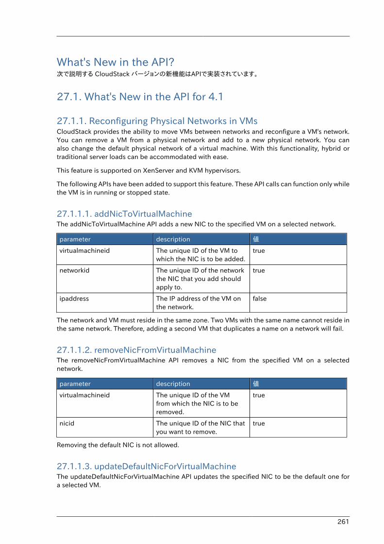
261
What's New in the API?次で説明する CloudStack バージョンの新機能はAPIで実装されています。
27.1. What's New in the API for 4.1
27.1.1. Reconfiguring Physical Networks in VMsCloudStack provides the ability to move VMs between networks and reconfigure a VM's network.You can remove a VM from a physical network and add to a new physical network. You canalso change the default physical network of a virtual machine. With this functionality, hybrid ortraditional server loads can be accommodated with ease.
This feature is supported on XenServer and KVM hypervisors.
The following APIs have been added to support this feature. These API calls can function only whilethe VM is in running or stopped state.
27.1.1.1. addNicToVirtualMachineThe addNicToVirtualMachine API adds a new NIC to the specified VM on a selected network.
parameter description 値
virtualmachineid The unique ID of the VM towhich the NIC is to be added.
true
networkid The unique ID of the networkthe NIC that you add shouldapply to.
true
ipaddress The IP address of the VM onthe network.
false
The network and VM must reside in the same zone. Two VMs with the same name cannot reside inthe same network. Therefore, adding a second VM that duplicates a name on a network will fail.
27.1.1.2. removeNicFromVirtualMachineThe removeNicFromVirtualMachine API removes a NIC from the specified VM on a selectednetwork.
parameter description 値
virtualmachineid The unique ID of the VMfrom which the NIC is to beremoved.
true
nicid The unique ID of the NIC thatyou want to remove.
true
Removing the default NIC is not allowed.
27.1.1.3. updateDefaultNicForVirtualMachineThe updateDefaultNicForVirtualMachine API updates the specified NIC to be the default one fora selected VM.
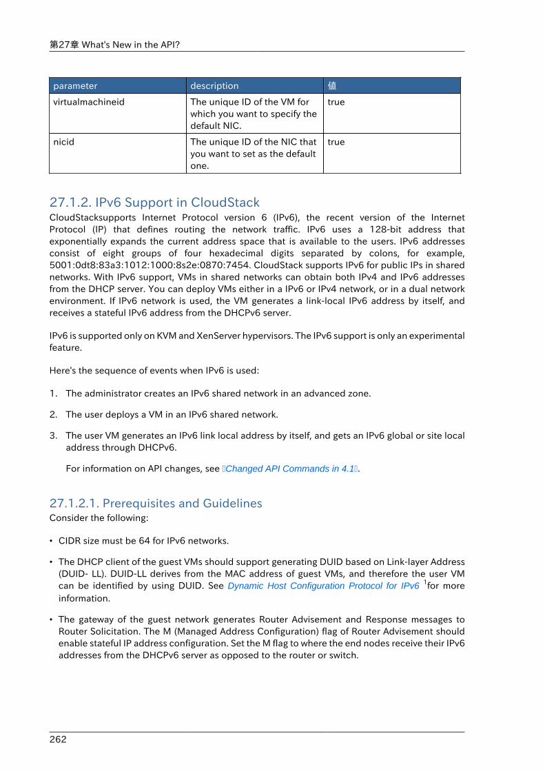
第27章 What's New in the API?
262
parameter description 値
virtualmachineid The unique ID of the VM forwhich you want to specify thedefault NIC.
true
nicid The unique ID of the NIC thatyou want to set as the defaultone.
true
27.1.2. IPv6 Support in CloudStackCloudStacksupports Internet Protocol version 6 (IPv6), the recent version of the InternetProtocol (IP) that defines routing the network traffic. IPv6 uses a 128-bit address thatexponentially expands the current address space that is available to the users. IPv6 addressesconsist of eight groups of four hexadecimal digits separated by colons, for example,5001:0dt8:83a3:1012:1000:8s2e:0870:7454. CloudStack supports IPv6 for public IPs in sharednetworks. With IPv6 support, VMs in shared networks can obtain both IPv4 and IPv6 addressesfrom the DHCP server. You can deploy VMs either in a IPv6 or IPv4 network, or in a dual networkenvironment. If IPv6 network is used, the VM generates a link-local IPv6 address by itself, andreceives a stateful IPv6 address from the DHCPv6 server.
IPv6 is supported only on KVM and XenServer hypervisors. The IPv6 support is only an experimentalfeature.
Here's the sequence of events when IPv6 is used:
1. The administrator creates an IPv6 shared network in an advanced zone.
2. The user deploys a VM in an IPv6 shared network.
3. The user VM generates an IPv6 link local address by itself, and gets an IPv6 global or site localaddress through DHCPv6.
For information on API changes, see �Changed API Commands in 4.1�.
27.1.2.1. Prerequisites and GuidelinesConsider the following:
• CIDR size must be 64 for IPv6 networks.
• The DHCP client of the guest VMs should support generating DUID based on Link-layer Address(DUID- LL). DUID-LL derives from the MAC address of guest VMs, and therefore the user VMcan be identified by using DUID. See Dynamic Host Configuration Protocol for IPv6 1for moreinformation.
• The gateway of the guest network generates Router Advisement and Response messages toRouter Solicitation. The M (Managed Address Configuration) flag of Router Advisement shouldenable stateful IP address configuration. Set the M flag to where the end nodes receive their IPv6addresses from the DHCPv6 server as opposed to the router or switch.
IPv6 Support in CloudStack
263
注記The M flag is the 1-bit Managed Address Configuration flag for RouterAdvisement. When set, Dynamic Host Configuration Protocol (DHCPv6) isavailable for address configuration in addition to any IPs set by using statelessaddress auto-configuration.
• Use the System VM template exclusively designed to support IPv6. Download the System VMtemplate from http://cloudstack.apt-get.eu/systemvm/.
• The concept of Default Network applies to IPv6 networks. However, unlike IPv4 CloudStack doesnot control the routing information of IPv6 in shared network; the choice of Default Network willnot affect the routing in the user VM.
• In a multiple shared network, the default route is set by the rack router, rather than the DHCPserver, which is out of CloudStack control. Therefore, in order for the user VM to get only thedefault route from the default NIC, modify the configuration of the user VM, and set non-defaultNIC's accept_ra to 0 explicitly. The accept_ra parameter accepts Router Advertisements and auto-configure /proc/sys/net/ipv6/conf/interface with received data.
27.1.2.2. Limitations of IPv6 in CloudStackThe following are not yet supported:
1. Security groups
2. Userdata and metadata
3. Passwords
27.1.2.3. Guest VM Configuration for DHCPv6For the guest VMs to get IPv6 address, run dhclient command manually on each of the VMs. UseDUID-LL to set up dhclient.
注記The IPv6 address is lost when a VM is stopped and started. Therefore, use the sameprocedure to get an IPv6 address when a VM is stopped and started.
1. Set up dhclient by using DUID-LL.
Perform the following for DHCP Client 4.2 and above:
a. Run the following command on the selected VM to get the dhcpv6 offer from VR:
dhclient -6 -D LL <dev>
Perform the following for DHCP Client 4.1:
a. Open the following to the dhclient configuration file:
第27章 What's New in the API?
264
vi /etc/dhcp/dhclient.conf
b. Add the following to the dhclient configuration file:
send dhcp6.client-id = concat(00:03:00, hardware);
2. Get IPv6 address from DHCP server as part of the system or network restart.
Based on the operating systems, perform the following:
On CentOS 6.2:
a. Open the Ethernet interface configuration file:
vi /etc/sysconfig/network-scripts/ifcfg-eth0
The ifcfg-eth0 file controls the first NIC in a system.
b. Make the necessary configuration changes, as given below:
DEVICE=eth0HWADDR=06:A0:F0:00:00:38NM_CONTROLLED=noONBOOT=yesBOOTPROTO=dhcp6TYPE=EthernetUSERCTL=noPEERDNS=yesIPV6INIT=yesDHCPV6C=yes
c. Open the following:
vi /etc/sysconfig/network
d. Make the necessary configuration changes, as given below:
NETWORKING=yesHOSTNAME=centos62mgmt.lab.vmops.comNETWORKING_IPV6=yesIPV6_AUTOCONF=no
On Ubuntu 12.10
a. Open the following:
etc/network/interfaces:
b. Make the necessary configuration changes, as given below:
iface eth0 inet6 dhcpautoconf 0
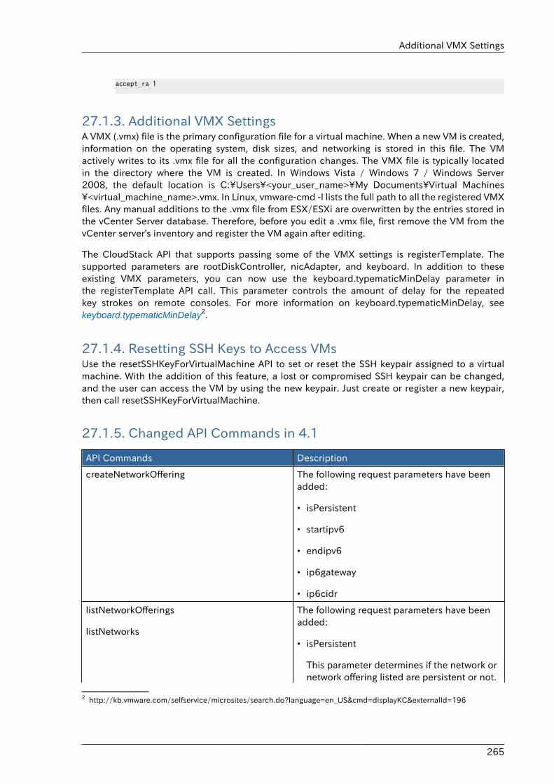
Additional VMX Settings
265
accept_ra 1
27.1.3. Additional VMX SettingsA VMX (.vmx) file is the primary configuration file for a virtual machine. When a new VM is created,information on the operating system, disk sizes, and networking is stored in this file. The VMactively writes to its .vmx file for all the configuration changes. The VMX file is typically locatedin the directory where the VM is created. In Windows Vista / Windows 7 / Windows Server2008, the default location is C:\Users\<your_user_name>\My Documents\Virtual Machines\<virtual_machine_name>.vmx. In Linux, vmware-cmd -l lists the full path to all the registered VMXfiles. Any manual additions to the .vmx file from ESX/ESXi are overwritten by the entries stored inthe vCenter Server database. Therefore, before you edit a .vmx file, first remove the VM from thevCenter server's inventory and register the VM again after editing.
The CloudStack API that supports passing some of the VMX settings is registerTemplate. Thesupported parameters are rootDiskController, nicAdapter, and keyboard. In addition to theseexisting VMX parameters, you can now use the keyboard.typematicMinDelay parameter inthe registerTemplate API call. This parameter controls the amount of delay for the repeatedkey strokes on remote consoles. For more information on keyboard.typematicMinDelay, seekeyboard.typematicMinDelay2.
27.1.4. Resetting SSH Keys to Access VMsUse the resetSSHKeyForVirtualMachine API to set or reset the SSH keypair assigned to a virtualmachine. With the addition of this feature, a lost or compromised SSH keypair can be changed,and the user can access the VM by using the new keypair. Just create or register a new keypair,then call resetSSHKeyForVirtualMachine.
27.1.5. Changed API Commands in 4.1
API Commands Description
createNetworkOffering The following request parameters have beenadded:
• isPersistent
• startipv6
• endipv6
• ip6gateway
• ip6cidr
listNetworkOfferings
listNetworks
The following request parameters have beenadded:
• isPersistent
This parameter determines if the network ornetwork offering listed are persistent or not.
2 http://kb.vmware.com/selfservice/microsites/search.do?language=en_US&cmd=displayKC&externalId=196
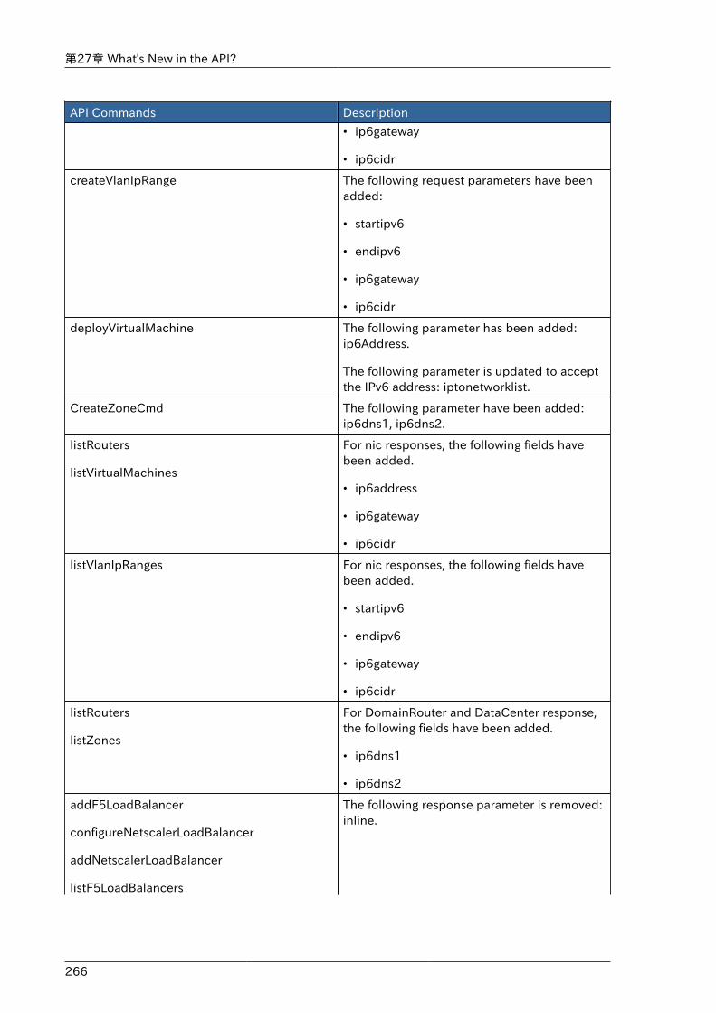
第27章 What's New in the API?
266
API Commands Description
• ip6gateway
• ip6cidr
createVlanIpRange The following request parameters have beenadded:
• startipv6
• endipv6
• ip6gateway
• ip6cidr
deployVirtualMachine The following parameter has been added:ip6Address.
The following parameter is updated to acceptthe IPv6 address: iptonetworklist.
CreateZoneCmd The following parameter have been added:ip6dns1, ip6dns2.
listRouters
listVirtualMachines
For nic responses, the following fields havebeen added.
• ip6address
• ip6gateway
• ip6cidr
listVlanIpRanges For nic responses, the following fields havebeen added.
• startipv6
• endipv6
• ip6gateway
• ip6cidr
listRouters
listZones
For DomainRouter and DataCenter response,the following fields have been added.
• ip6dns1
• ip6dns2
addF5LoadBalancer
configureNetscalerLoadBalancer
addNetscalerLoadBalancer
listF5LoadBalancers
The following response parameter is removed:inline.
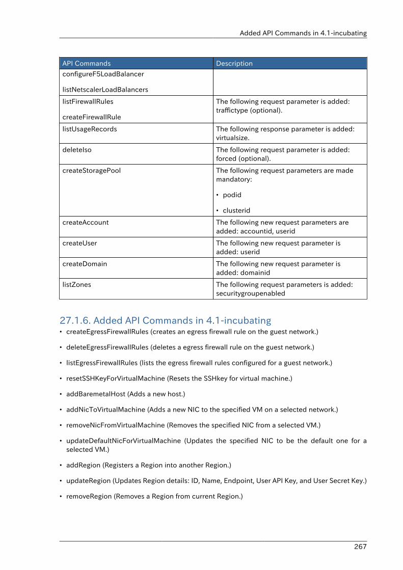
Added API Commands in 4.1-incubating
267
API Commands Description
configureF5LoadBalancer
listNetscalerLoadBalancers
listFirewallRules
createFirewallRule
The following request parameter is added:traffictype (optional).
listUsageRecords The following response parameter is added:virtualsize.
deleteIso The following request parameter is added:forced (optional).
createStoragePool The following request parameters are mademandatory:
• podid
• clusterid
createAccount The following new request parameters areadded: accountid, userid
createUser The following new request parameter isadded: userid
createDomain The following new request parameter isadded: domainid
listZones The following request parameters is added:securitygroupenabled
27.1.6. Added API Commands in 4.1-incubating• createEgressFirewallRules (creates an egress firewall rule on the guest network.)
• deleteEgressFirewallRules (deletes a egress firewall rule on the guest network.)
• listEgressFirewallRules (lists the egress firewall rules configured for a guest network.)
• resetSSHKeyForVirtualMachine (Resets the SSHkey for virtual machine.)
• addBaremetalHost (Adds a new host.)
• addNicToVirtualMachine (Adds a new NIC to the specified VM on a selected network.)
• removeNicFromVirtualMachine (Removes the specified NIC from a selected VM.)
• updateDefaultNicForVirtualMachine (Updates the specified NIC to be the default one for aselected VM.)
• addRegion (Registers a Region into another Region.)
• updateRegion (Updates Region details: ID, Name, Endpoint, User API Key, and User Secret Key.)
• removeRegion (Removes a Region from current Region.)
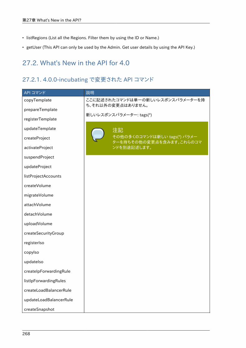
第27章 What's New in the API?
268
• listRegions (List all the Regions. Filter them by using the ID or Name.)
• getUser (This API can only be used by the Admin. Get user details by using the API Key.)
27.2. What's New in the API for 4.0
27.2.1. 4.0.0-incubating で変更された API コマンド
API コマンド 説明
copyTemplate
prepareTemplate
registerTemplate
updateTemplate
createProject
activateProject
suspendProject
updateProject
listProjectAccounts
createVolume
migrateVolume
attachVolume
detachVolume
uploadVolume
createSecurityGroup
registerIso
copyIso
updateIso
createIpForwardingRule
listIpForwardingRules
createLoadBalancerRule
updateLoadBalancerRule
createSnapshot
ここに記述されたコマンドは単一の新しいレスポンスパラメーターを持ち、それ以外の変更点はありません。
新しいレスポンスパラメーター: tags(*)
注記その他の多くのコマンドは新しい tags(*) パラメーターを持ちその他の変更点を含みます。これらのコマンドを別途記述します。
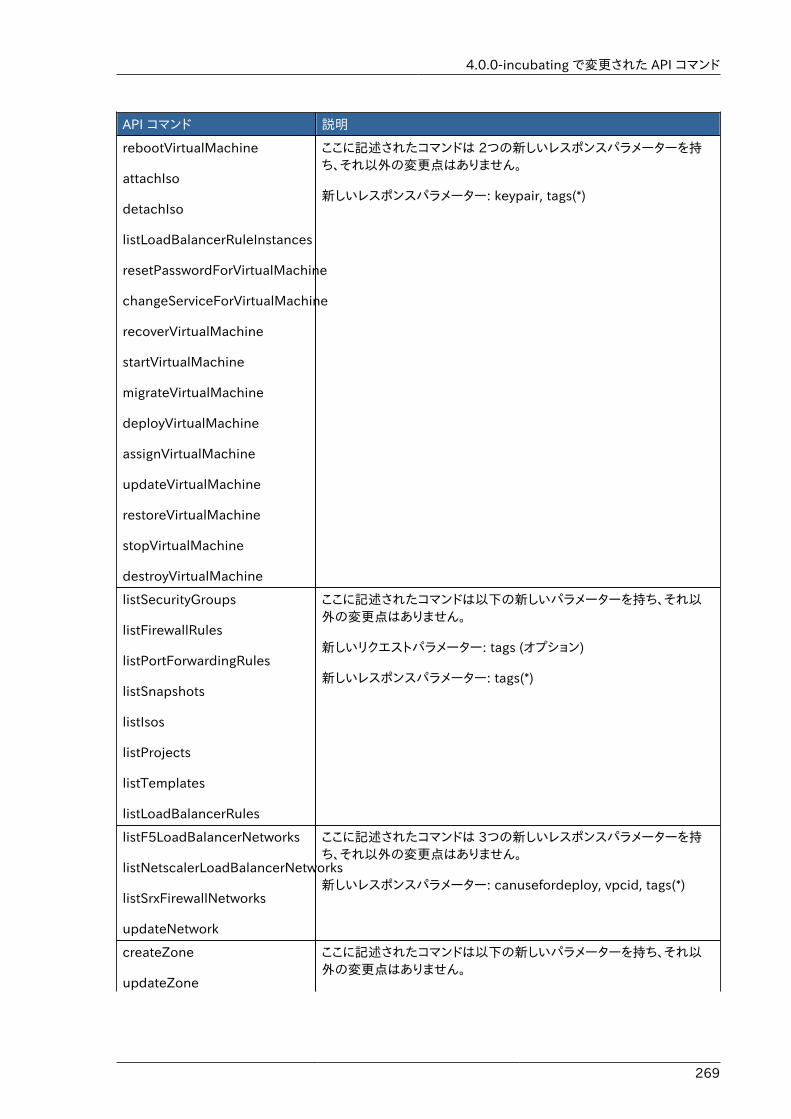
4.0.0-incubating で変更された API コマンド
269
API コマンド 説明
rebootVirtualMachine
attachIso
detachIso
listLoadBalancerRuleInstances
resetPasswordForVirtualMachine
changeServiceForVirtualMachine
recoverVirtualMachine
startVirtualMachine
migrateVirtualMachine
deployVirtualMachine
assignVirtualMachine
updateVirtualMachine
restoreVirtualMachine
stopVirtualMachine
destroyVirtualMachine
ここに記述されたコマンドは 2つの新しいレスポンスパラメーターを持ち、それ以外の変更点はありません。
新しいレスポンスパラメーター: keypair, tags(*)
listSecurityGroups
listFirewallRules
listPortForwardingRules
listSnapshots
listIsos
listProjects
listTemplates
listLoadBalancerRules
ここに記述されたコマンドは以下の新しいパラメーターを持ち、それ以外の変更点はありません。
新しいリクエストパラメーター: tags (オプション)
新しいレスポンスパラメーター: tags(*)
listF5LoadBalancerNetworks
listNetscalerLoadBalancerNetworks
listSrxFirewallNetworks
updateNetwork
ここに記述されたコマンドは 3つの新しいレスポンスパラメーターを持ち、それ以外の変更点はありません。
新しいレスポンスパラメーター: canusefordeploy, vpcid, tags(*)
createZone
updateZone
ここに記述されたコマンドは以下の新しいパラメーターを持ち、それ以外の変更点はありません。
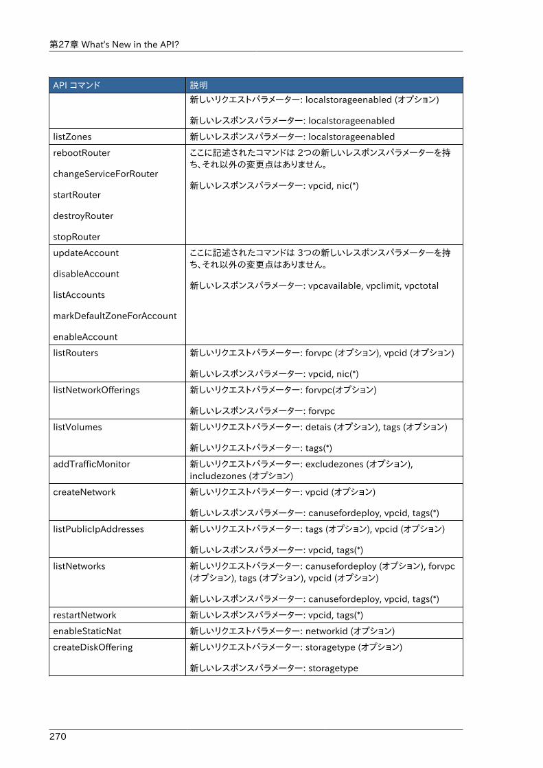
第27章 What's New in the API?
270
API コマンド 説明
新しいリクエストパラメーター: localstorageenabled (オプション)
新しいレスポンスパラメーター: localstorageenabled
listZones 新しいレスポンスパラメーター: localstorageenabled
rebootRouter
changeServiceForRouter
startRouter
destroyRouter
stopRouter
ここに記述されたコマンドは 2つの新しいレスポンスパラメーターを持ち、それ以外の変更点はありません。
新しいレスポンスパラメーター: vpcid, nic(*)
updateAccount
disableAccount
listAccounts
markDefaultZoneForAccount
enableAccount
ここに記述されたコマンドは 3つの新しいレスポンスパラメーターを持ち、それ以外の変更点はありません。
新しいレスポンスパラメーター: vpcavailable, vpclimit, vpctotal
listRouters 新しいリクエストパラメーター: forvpc (オプション), vpcid (オプション)
新しいレスポンスパラメーター: vpcid, nic(*)
listNetworkOfferings 新しいリクエストパラメーター: forvpc(オプション)
新しいレスポンスパラメーター: forvpc
listVolumes 新しいリクエストパラメーター: detais (オプション), tags (オプション)
新しいリクエストパラメーター: tags(*)
addTrafficMonitor 新しいリクエストパラメーター: excludezones (オプション),includezones (オプション)
createNetwork 新しいリクエストパラメーター: vpcid (オプション)
新しいレスポンスパラメーター: canusefordeploy, vpcid, tags(*)
listPublicIpAddresses 新しいリクエストパラメーター: tags (オプション), vpcid (オプション)
新しいレスポンスパラメーター: vpcid, tags(*)
listNetworks 新しいリクエストパラメーター: canusefordeploy (オプション), forvpc(オプション), tags (オプション), vpcid (オプション)
新しいレスポンスパラメーター: canusefordeploy, vpcid, tags(*)
restartNetwork 新しいレスポンスパラメーター: vpcid, tags(*)
enableStaticNat 新しいリクエストパラメーター: networkid (オプション)
createDiskOffering 新しいリクエストパラメーター: storagetype (オプション)
新しいレスポンスパラメーター: storagetype
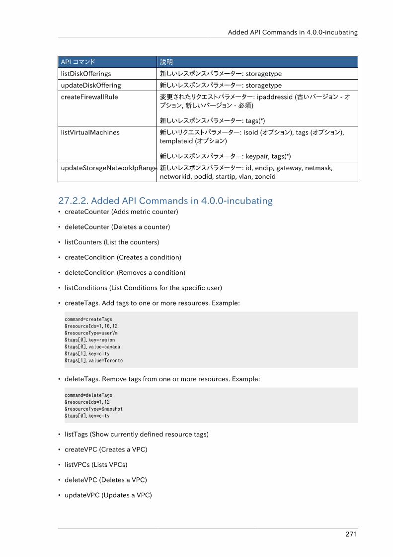
Added API Commands in 4.0.0-incubating
271
API コマンド 説明
listDiskOfferings 新しいレスポンスパラメーター: storagetype
updateDiskOffering 新しいレスポンスパラメーター: storagetype
createFirewallRule 変更されたリクエストパラメーター: ipaddressid (古いバージョン - オプション, 新しいバージョン - 必須)
新しいレスポンスパラメーター: tags(*)
listVirtualMachines 新しいリクエストパラメーター: isoid (オプション), tags (オプション),templateid (オプション)
新しいレスポンスパラメーター: keypair, tags(*)
updateStorageNetworkIpRange 新しいレスポンスパラメーター: id, endip, gateway, netmask,networkid, podid, startip, vlan, zoneid
27.2.2. Added API Commands in 4.0.0-incubating• createCounter (Adds metric counter)
• deleteCounter (Deletes a counter)
• listCounters (List the counters)
• createCondition (Creates a condition)
• deleteCondition (Removes a condition)
• listConditions (List Conditions for the specific user)
• createTags. Add tags to one or more resources. Example:
command=createTags&resourceIds=1,10,12&resourceType=userVm&tags[0].key=region&tags[0].value=canada&tags[1].key=city&tags[1].value=Toronto
• deleteTags. Remove tags from one or more resources. Example:
command=deleteTags&resourceIds=1,12&resourceType=Snapshot&tags[0].key=city
• listTags (Show currently defined resource tags)
• createVPC (Creates a VPC)
• listVPCs (Lists VPCs)
• deleteVPC (Deletes a VPC)
• updateVPC (Updates a VPC)
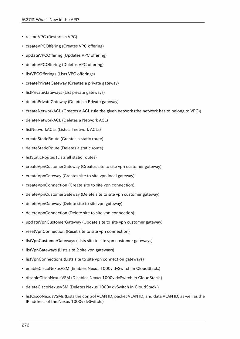
第27章 What's New in the API?
272
• restartVPC (Restarts a VPC)
• createVPCOffering (Creates VPC offering)
• updateVPCOffering (Updates VPC offering)
• deleteVPCOffering (Deletes VPC offering)
• listVPCOfferings (Lists VPC offerings)
• createPrivateGateway (Creates a private gateway)
• listPrivateGateways (List private gateways)
• deletePrivateGateway (Deletes a Private gateway)
• createNetworkACL (Creates a ACL rule the given network (the network has to belong to VPC))
• deleteNetworkACL (Deletes a Network ACL)
• listNetworkACLs (Lists all network ACLs)
• createStaticRoute (Creates a static route)
• deleteStaticRoute (Deletes a static route)
• listStaticRoutes (Lists all static routes)
• createVpnCustomerGateway (Creates site to site vpn customer gateway)
• createVpnGateway (Creates site to site vpn local gateway)
• createVpnConnection (Create site to site vpn connection)
• deleteVpnCustomerGateway (Delete site to site vpn customer gateway)
• deleteVpnGateway (Delete site to site vpn gateway)
• deleteVpnConnection (Delete site to site vpn connection)
• updateVpnCustomerGateway (Update site to site vpn customer gateway)
• resetVpnConnection (Reset site to site vpn connection)
• listVpnCustomerGateways (Lists site to site vpn customer gateways)
• listVpnGateways (Lists site 2 site vpn gateways)
• listVpnConnections (Lists site to site vpn connection gateways)
• enableCiscoNexusVSM (Enables Nexus 1000v dvSwitch in CloudStack.)
• disableCiscoNexusVSM (Disables Nexus 1000v dvSwitch in CloudStack.)
• deleteCiscoNexusVSM (Deletes Nexus 1000v dvSwitch in CloudStack.)
• listCiscoNexusVSMs (Lists the control VLAN ID, packet VLAN ID, and data VLAN ID, as well as theIP address of the Nexus 1000v dvSwitch.)
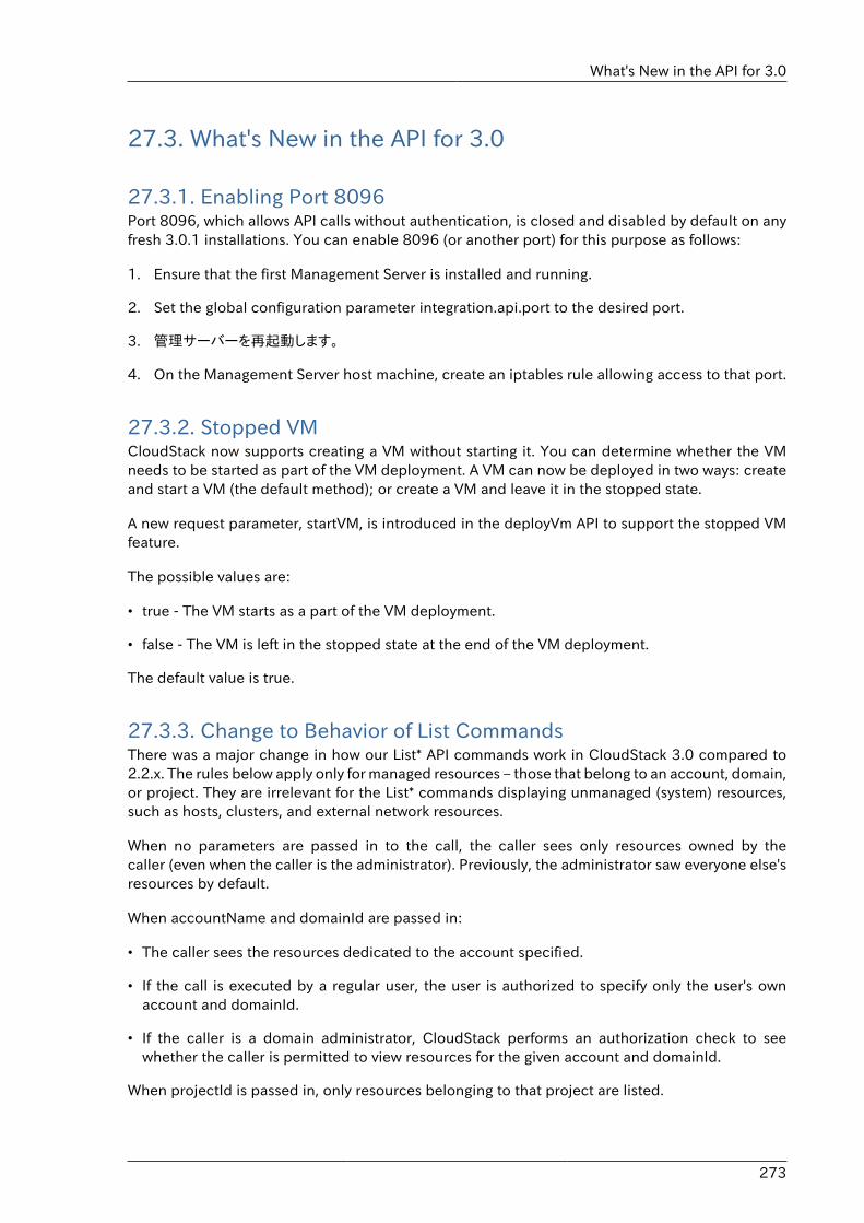
What's New in the API for 3.0
273
27.3. What's New in the API for 3.0
27.3.1. Enabling Port 8096Port 8096, which allows API calls without authentication, is closed and disabled by default on anyfresh 3.0.1 installations. You can enable 8096 (or another port) for this purpose as follows:
1. Ensure that the first Management Server is installed and running.
2. Set the global configuration parameter integration.api.port to the desired port.
3. 管理サーバーを再起動します。
4. On the Management Server host machine, create an iptables rule allowing access to that port.
27.3.2. Stopped VMCloudStack now supports creating a VM without starting it. You can determine whether the VMneeds to be started as part of the VM deployment. A VM can now be deployed in two ways: createand start a VM (the default method); or create a VM and leave it in the stopped state.
A new request parameter, startVM, is introduced in the deployVm API to support the stopped VMfeature.
The possible values are:
• true - The VM starts as a part of the VM deployment.
• false - The VM is left in the stopped state at the end of the VM deployment.
The default value is true.
27.3.3. Change to Behavior of List CommandsThere was a major change in how our List* API commands work in CloudStack 3.0 compared to2.2.x. The rules below apply only for managed resources – those that belong to an account, domain,or project. They are irrelevant for the List* commands displaying unmanaged (system) resources,such as hosts, clusters, and external network resources.
When no parameters are passed in to the call, the caller sees only resources owned by thecaller (even when the caller is the administrator). Previously, the administrator saw everyone else'sresources by default.
When accountName and domainId are passed in:
• The caller sees the resources dedicated to the account specified.
• If the call is executed by a regular user, the user is authorized to specify only the user's ownaccount and domainId.
• If the caller is a domain administrator, CloudStack performs an authorization check to seewhether the caller is permitted to view resources for the given account and domainId.
When projectId is passed in, only resources belonging to that project are listed.
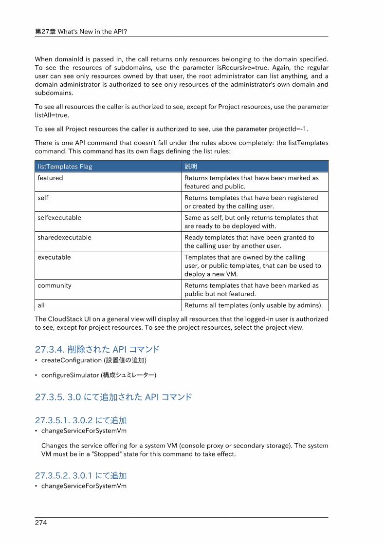
第27章 What's New in the API?
274
When domainId is passed in, the call returns only resources belonging to the domain specified.To see the resources of subdomains, use the parameter isRecursive=true. Again, the regularuser can see only resources owned by that user, the root administrator can list anything, and adomain administrator is authorized to see only resources of the administrator's own domain andsubdomains.
To see all resources the caller is authorized to see, except for Project resources, use the parameterlistAll=true.
To see all Project resources the caller is authorized to see, use the parameter projectId=-1.
There is one API command that doesn't fall under the rules above completely: the listTemplatescommand. This command has its own flags defining the list rules:
listTemplates Flag 説明
featured Returns templates that have been marked asfeatured and public.
self Returns templates that have been registeredor created by the calling user.
selfexecutable Same as self, but only returns templates thatare ready to be deployed with.
sharedexecutable Ready templates that have been granted tothe calling user by another user.
executable Templates that are owned by the callinguser, or public templates, that can be used todeploy a new VM.
community Returns templates that have been marked aspublic but not featured.
all Returns all templates (only usable by admins).
The CloudStack UI on a general view will display all resources that the logged-in user is authorizedto see, except for project resources. To see the project resources, select the project view.
27.3.4. 削除された API コマンド• createConfiguration (設置値の追加)
• configureSimulator (構成シュミレーター)
27.3.5. 3.0 にて追加された API コマンド
27.3.5.1. 3.0.2 にて追加• changeServiceForSystemVm
Changes the service offering for a system VM (console proxy or secondary storage). The systemVM must be in a "Stopped" state for this command to take effect.
27.3.5.2. 3.0.1 にて追加• changeServiceForSystemVm
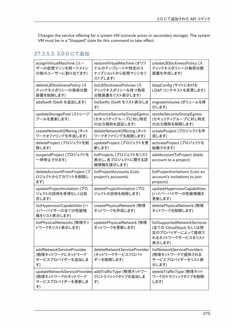
3.0 にて追加された API コマンド
275
Changes the service offering for a system VM (console proxy or secondary storage). The systemVM must be in a "Stopped" state for this command to take effect.
27.3.5.3. 3.0.0 にて追加
assignVirtualMachine (ユーザーの仮想マシンを同一ドメインの他のユーザーに割り当てます)
restoreVirtualMachine (オリジナルのテンプレートや特定のスナップショットから仮想マシンをリストアします)
createLBStickinessPolicy (スティックネスポリシーの負荷分散装置を作成します)
deleteLBStickinessPolicy (スティックネスポリシーの負荷分散装置を削除します)
listLBStickinessPolicies (スティックネスポリシーを持つ負荷分散装置をリスト表示します)
ldapConfig (サイトにおけるLDAP コンテキストを変更します)
addSwift (Swift を追加します) listSwifts (Swift をリスト表示します)
migrateVolume (ボリュームを移行します)
updateStoragePool (ストレージプールを更新します)
authorizeSecurityGroupEgress(セキュリティグループに対し特定の出力規則を認証します)
revokeSecurityGroupEgress(セキュリティグループに対し特定の出力規則を削除します)
createNetworkOffering (ネットワークオファリングを作成します)
deleteNetworkOffering (ネットワークオファリングを削除します)
createProject (プロジェクトを作成します)
deleteProject (プロジェクトを削除します)
updateProject (プロジェクトを更新します)
activateProject (プロジェクトを始動させます)
suspendProject (プロジェクトを一時停止させます)
listProjects (プロジェクトをリスト表示し、各プロジェクトに関する詳細情報を提示します)
addAccountToProject (Addsaccount to a project)
deleteAccountFromProject (プロジェクトからアカウントを削除します)
listProjectAccounts (Listsproject's accounts)
listProjectInvitations (Lists anaccount's invitations to joinprojects)
updateProjectInvitation (プロジェクトの招待を受理もしくは拒否します)
deleteProjectInvitation (プロジェクトの招待を削除します)
updateHypervisorCapabilities(ハイパーバイザーの性能情報を更新します)
listHypervisorCapabilities (ハイパーバイザーの全ての性能情報をリスト表示します)
createPhysicalNetwork (物理ネットワークを作成します)
deletePhysicalNetwork (物理ネットワークを削除します)
listPhysicalNetworks (物理ネットワークをリスト表示します)
updatePhysicalNetwork (物理ネットワークを更新します)
listSupportedNetworkServices(全ての CloudStack もしくは特定のプロバイダーによって提供されるネットワークサービスをリスト表示します)
addNetworkServiceProvider(物理ネットワークにネットワークサービスプロバイダーを追加します)
deleteNetworkServiceProvider(ネットワークサービスプロバイダーを削除します)
listNetworkServiceProviders(物理ネットワークで提供されるサービスプロバイダーをリスト表示します)
updateNetworkServiceProvider(物理ネットワークのネットワークサービスプロバイダーを更新します)
addTrafficType (物理ネットワークにトラフィックタイプを追加します)
deleteTrafficType (物理ネットワークのトラフィックタイプを削除します)
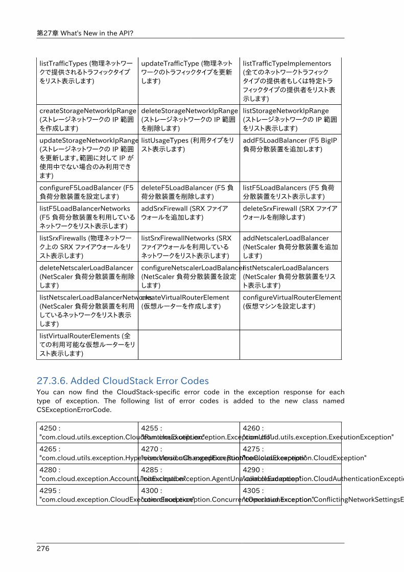
第27章 What's New in the API?
276
listTrafficTypes (物理ネットワークで提供されるトラフィックタイプをリスト表示します)
updateTrafficType (物理ネットワークのトラフィックタイプを更新します)
listTrafficTypeImplementors(全てのネットワークトラフィックタイプの提供者もしくは特定トラフィックタイプの提供者をリスト表示します)
createStorageNetworkIpRange(ストレージネットワークの IP 範囲を作成します)
deleteStorageNetworkIpRange(ストレージネットワークの IP 範囲を削除します)
listStorageNetworkIpRange(ストレージネットワークの IP 範囲をリスト表示します)
updateStorageNetworkIpRange(ストレージネットワークの IP 範囲を更新します。範囲に対して IP が使用中でない場合のみ利用できます)
listUsageTypes (利用タイプをリスト表示します)
addF5LoadBalancer (F5 BigIP負荷分散装置を追加します)
configureF5LoadBalancer (F5負荷分散装置を設定します)
deleteF5LoadBalancer (F5 負荷分散装置を削除します)
listF5LoadBalancers (F5 負荷分散装置をリスト表示します)
listF5LoadBalancerNetworks(F5 負荷分散装置を利用しているネットワークをリスト表示します)
addSrxFirewall (SRX ファイアウォールを追加します)
deleteSrxFirewall (SRX ファイアウォールを削除します)
listSrxFirewalls (物理ネットワーク上の SRX ファイアウォールをリスト表示します)
listSrxFirewallNetworks (SRXファイアウォールを利用しているネットワークをリスト表示します)
addNetscalerLoadBalancer(NetScaler 負荷分散装置を追加します)
deleteNetscalerLoadBalancer(NetScaler 負荷分散装置を削除します)
configureNetscalerLoadBalancer(NetScaler 負荷分散装置を設定します)
listNetscalerLoadBalancers(NetScaler 負荷分散装置をリスト表示します)
listNetscalerLoadBalancerNetworks(NetScaler 負荷分散装置を利用しているネットワークをリスト表示します)
createVirtualRouterElement(仮想ルーターを作成します)
configureVirtualRouterElement(仮想マシンを設定します)
listVirtualRouterElements (全ての利用可能な仮想ルーターをリスト表示します)
27.3.6. Added CloudStack Error CodesYou can now find the CloudStack-specific error code in the exception response for eachtype of exception. The following list of error codes is added to the new class namedCSExceptionErrorCode.
4250 :"com.cloud.utils.exception.CloudRuntimeException"
4255 :"com.cloud.utils.exception.ExceptionUtil"
4260 :"com.cloud.utils.exception.ExecutionException"
4265 :"com.cloud.utils.exception.HypervisorVersionChangedException"
4270 :"com.cloud.utils.exception.RuntimeCloudException"
4275 :"com.cloud.exception.CloudException"
4280 :"com.cloud.exception.AccountLimitException"
4285 :"com.cloud.exception.AgentUnavailableException"
4290 :"com.cloud.exception.CloudAuthenticationException"
4295 :"com.cloud.exception.CloudExecutionException"
4300 :"com.cloud.exception.ConcurrentOperationException"
4305 :"com.cloud.exception.ConflictingNetworkSettingsException"
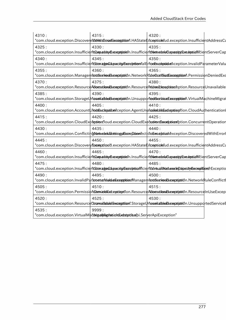
Added CloudStack Error Codes
277
4310 :"com.cloud.exception.DiscoveredWithErrorException"
4315 :"com.cloud.exception.HAStateException"
4320 :"com.cloud.exception.InsufficientAddressCapacityException"
4325 :"com.cloud.exception.InsufficientCapacityException"
4330 :"com.cloud.exception.InsufficientNetworkCapacityException"
4335 :"com.cloud.exception.InsufficientServerCapacityException"
4340 :"com.cloud.exception.InsufficientStorageCapacityException"
4345 :"com.cloud.exception.InternalErrorException"
4350 :"com.cloud.exception.InvalidParameterValueException"
4355 :"com.cloud.exception.ManagementServerException"
4360 :"com.cloud.exception.NetworkRuleConflictException"
4365 :"com.cloud.exception.PermissionDeniedException"
4370 :"com.cloud.exception.ResourceAllocationException"
4375 :"com.cloud.exception.ResourceInUseException"
4380 :"com.cloud.exception.ResourceUnavailableException"
4385 :"com.cloud.exception.StorageUnavailableException"
4390 :"com.cloud.exception.UnsupportedServiceException"
4395 :"com.cloud.exception.VirtualMachineMigrationException"
4400 :"com.cloud.exception.AccountLimitException"
4405 :"com.cloud.exception.AgentUnavailableException"
4410 :"com.cloud.exception.CloudAuthenticationException"
4415 :"com.cloud.exception.CloudException"
4420 :"com.cloud.exception.CloudExecutionException"
4425 :"com.cloud.exception.ConcurrentOperationException"
4430 :"com.cloud.exception.ConflictingNetworkSettingsException"
4435 :"com.cloud.exception.ConnectionException"
4440 :"com.cloud.exception.DiscoveredWithErrorException"
4445 :"com.cloud.exception.DiscoveryException"
4450 :"com.cloud.exception.HAStateException"
4455 :"com.cloud.exception.InsufficientAddressCapacityException"
4460 :"com.cloud.exception.InsufficientCapacityException"
4465 :"com.cloud.exception.InsufficientNetworkCapacityException"
4470 :"com.cloud.exception.InsufficientServerCapacityException"
4475 :"com.cloud.exception.InsufficientStorageCapacityException"
4480 :"com.cloud.exception.InsufficientVirtualNetworkCapcityException"
4485 :"com.cloud.exception.InternalErrorException"
4490 :"com.cloud.exception.InvalidParameterValueException"
4495 :"com.cloud.exception.ManagementServerException"
4500 :"com.cloud.exception.NetworkRuleConflictException"
4505 :"com.cloud.exception.PermissionDeniedException"
4510 :"com.cloud.exception.ResourceAllocationException"
4515 :"com.cloud.exception.ResourceInUseException"
4520 :"com.cloud.exception.ResourceUnavailableException"
4525 :"com.cloud.exception.StorageUnavailableException"
4530 :"com.cloud.exception.UnsupportedServiceException"
4535 :"com.cloud.exception.VirtualMachineMigrationException"
9999 :"org.apache.cloudstack.api.ServerApiException"

278
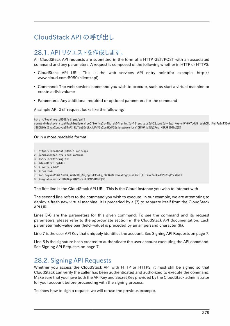
279
CloudStack API の呼び出し
28.1. API リクエストを作成します。All CloudStack API requests are submitted in the form of a HTTP GET/POST with an associatedcommand and any parameters. A request is composed of the following whether in HTTP or HTTPS:
• CloudStack API URL: This is the web services API entry point(for example, http://www.cloud.com:8080/client/api)
• Command: The web services command you wish to execute, such as start a virtual machine orcreate a disk volume
• Parameters: Any additional required or optional parameters for the command
A sample API GET request looks like the following:
http://localhost:8080/client/api?command=deployVirtualMachine&serviceOfferingId=1&diskOfferingId=1&templateId=2&zoneId=4&apiKey=miVr6X7u6bN_sdahOBpjNejPgEsT35eXq-jB8CG20YI3yaxXcgpyuaIRmFI_EJTVwZ0nUkkJbPmY3y2bciKwFQ&signature=Lxx1DM40AjcXU%2FcaiK8RAP0O1hU%3D
Or in a more readable format:
1. http://localhost:8080/client/api2. ?command=deployVirtualMachine3. &serviceOfferingId=14. &diskOfferingId=15. &templateId=26. &zoneId=47. &apiKey=miVr6X7u6bN_sdahOBpjNejPgEsT35eXqjB8CG20YI3yaxXcgpyuaIRmFI_EJTVwZ0nUkkJbPmY3y2bciKwFQ8. &signature=Lxx1DM40AjcXU%2FcaiK8RAP0O1hU%3D
The first line is the CloudStack API URL. This is the Cloud instance you wish to interact with.
The second line refers to the command you wish to execute. In our example, we are attempting todeploy a fresh new virtual machine. It is preceded by a (?) to separate itself from the CloudStackAPI URL.
Lines 3-6 are the parameters for this given command. To see the command and its requestparameters, please refer to the appropriate section in the CloudStack API documentation. Eachparameter field-value pair (field=value) is preceded by an ampersand character (&).
Line 7 is the user API Key that uniquely identifies the account. See Signing API Requests on page 7.
Line 8 is the signature hash created to authenticate the user account executing the API command.See Signing API Requests on page 7.
28.2. Signing API RequestsWhether you access the CloudStack API with HTTP or HTTPS, it must still be signed so thatCloudStack can verify the caller has been authenticated and authorized to execute the command.Make sure that you have both the API Key and Secret Key provided by the CloudStack administratorfor your account before proceeding with the signing process.
To show how to sign a request, we will re-use the previous example.
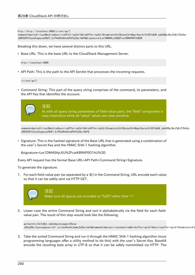
第28章 CloudStack API の呼び出し
280
http://http://localhost:8080/client/api?command=deployVirtualMachine&serviceOfferingId=1&diskOfferingId=1&templateId=2&zoneId=4&apiKey=miVr6X7u6bN_sdahOBpjNejPgEsT35eXq-jB8CG20YI3yaxXcgpyuaIRmFI_EJTVwZ0nUkkJbPmY3y2bciKwFQ&signature=Lxx1DM40AjcXU%2FcaiK8RAP0O1hU%3D
Breaking this down, we have several distinct parts to this URL.
• Base URL: This is the base URL to the CloudStack Management Server.
http://localhost:8080
• API Path: This is the path to the API Servlet that processes the incoming requests.
/client/api?
• Command String: This part of the query string comprises of the command, its parameters, andthe API Key that identifies the account.
注記As with all query string parameters of field-value pairs, the "field" component iscase insensitive while all "value" values are case sensitive.
command=deployVirtualMachine&serviceOfferingId=1&diskOfferingId=1&templateId=2&zoneId=4&apiKey=miVr6X7u6bN_sdahOBpjNejPgEsT35eXq-jB8CG20YI3yaxXcgpyuaIRmFI_EJTVwZ0nUkkJbPmY3y2bciKwFQ
• Signature: This is the hashed signature of the Base URL that is generated using a combination ofthe user’s Secret Key and the HMAC SHA-1 hashing algorithm.
&signature=Lxx1DM40AjcXU%2FcaiK8RAP0O1hU%3D
Every API request has the format Base URL+API Path+Command String+Signature.
To generate the signature.
1. For each field-value pair (as separated by a '&') in the Command String, URL encode each valueso that it can be safely sent via HTTP GET.
注記Make sure all spaces are encoded as "%20" rather than "+".
2. Lower case the entire Command String and sort it alphabetically via the field for each field-value pair. The result of this step would look like the following.
apikey=mivr6x7u6bn_sdahobpjnejpgest35exq-jb8cg20yi3yaxxcgpyuairmfi_ejtvwz0nukkjbpmy3y2bcikwfq&command=deployvirtualmachine&diskofferingid=1&serviceofferingid=1&templateid=2&zoneid=4
3. Take the sorted Command String and run it through the HMAC SHA-1 hashing algorithm (mostprogramming languages offer a utility method to do this) with the user’s Secret Key. Base64encode the resulting byte array in UTF-8 so that it can be safely transmitted via HTTP. The
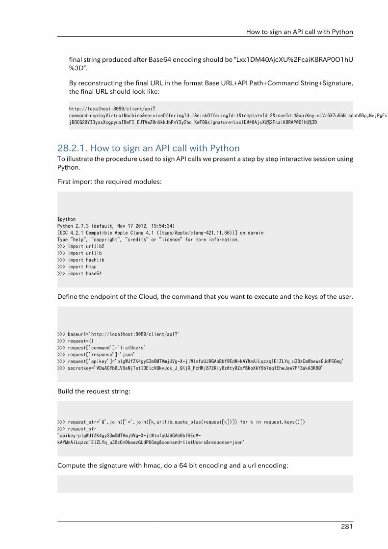
How to sign an API call with Python
281
final string produced after Base64 encoding should be "Lxx1DM40AjcXU%2FcaiK8RAP0O1hU%3D".
By reconstructing the final URL in the format Base URL+API Path+Command String+Signature,the final URL should look like:
http://localhost:8080/client/api?command=deployVirtualMachine&serviceOfferingId=1&diskOfferingId=1&templateId=2&zoneId=4&apiKey=miVr6X7u6bN_sdahOBpjNejPgEsT35eXq-jB8CG20YI3yaxXcgpyuaIRmFI_EJTVwZ0nUkkJbPmY3y2bciKwFQ&signature=Lxx1DM40AjcXU%2FcaiK8RAP0O1hU%3D
28.2.1. How to sign an API call with PythonTo illustrate the procedure used to sign API calls we present a step by step interactive session usingPython.
First import the required modules:
$pythonPython 2.7.3 (default, Nov 17 2012, 19:54:34) [GCC 4.2.1 Compatible Apple Clang 4.1 ((tags/Apple/clang-421.11.66))] on darwinType "help", "copyright", "credits" or "license" for more information.>>> import urllib2>>> import urllib>>> import hashlib>>> import hmac>>> import base64
Define the endpoint of the Cloud, the command that you want to execute and the keys of the user.
>>> baseurl='http://localhost:8080/client/api?'>>> request={}>>> request['command']='listUsers'>>> request['response']='json'>>> request['apikey']='plgWJfZK4gyS3mOMTVmjUVg-X-jlWlnfaUJ9GAbBbf9EdM-kAYMmAiLqzzq1ElZLYq_u38zCm0bewzGUdP66mg'>>> secretkey='VDaACYb0LV9eNjTetIOElcVQkvJck_J_QljX_FcHRj87ZKiy0z0ty0ZsYBkoXkY9b7eq1EhwJaw7FF3akA3KBQ'
Build the request string:
>>> request_str='&'.join(['='.join([k,urllib.quote_plus(request[k])]) for k in request.keys()])>>> request_str'apikey=plgWJfZK4gyS3mOMTVmjUVg-X-jlWlnfaUJ9GAbBbf9EdM-kAYMmAiLqzzq1ElZLYq_u38zCm0bewzGUdP66mg&command=listUsers&response=json'
Compute the signature with hmac, do a 64 bit encoding and a url encoding:
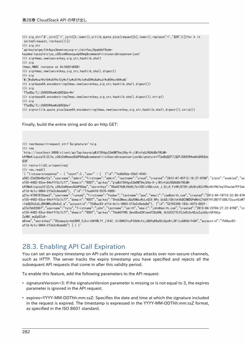
第28章 CloudStack API の呼び出し
282
>>> sig_str='&'.join(['='.join([k.lower(),urllib.quote_plus(request[k].lower().replace('+','%20'))])for k in sorted(request.iterkeys())]) >>> sig_str'apikey=plgwjfzk4gys3momtvmjuvg-x-jlwlnfauj9gabbbf9edm-kaymmailqzzq1elzlyq_u38zcm0bewzgudp66mg&command=listusers&response=json'>>> sig=hmac.new(secretkey,sig_str,hashlib.sha1)>>> sig<hmac.HMAC instance at 0x10d91d680>>>> sig=hmac.new(secretkey,sig_str,hashlib.sha1).digest()>>> sig'M:]\x0e\xaf\xfb\x8f\xf2y\xf1p\x91\x1e\x89\x8a\xa1\x05\xc4A\xdb'>>> sig=base64.encodestring(hmac.new(secretkey,sig_str,hashlib.sha1).digest())>>> sig'TTpdDq/7j/J58XCRHomKoQXEQds=\n'>>> sig=base64.encodestring(hmac.new(secretkey,sig_str,hashlib.sha1).digest()).strip()>>> sig'TTpdDq/7j/J58XCRHomKoQXEQds='>>> sig=urllib.quote_plus(base64.encodestring(hmac.new(secretkey,sig_str,hashlib.sha1).digest()).strip())
Finally, build the entire string and do an http GET:
>>> req=baseurl+request_str+'&signature='+sig>>> req'http://localhost:8080/client/api?apikey=plgWJfZK4gyS3mOMTVmjUVg-X-jlWlnfaUJ9GAbBbf9EdM-kAYMmAiLqzzq1ElZLYq_u38zCm0bewzGUdP66mg&command=listUsers&response=json&signature=TTpdDq%2F7j%2FJ58XCRHomKoQXEQds%3D'>>> res=urllib2.urlopen(req)>>> res.read()'{ "listusersresponse" : { "count":3 ,"user" : [ {"id":"7ed6d5da-93b2-4545-a502-23d20b48ef2a","username":"admin","firstname":"admin","lastname":"cloud","created":"2012-07-05T12:18:27-0700","state":"enabled","account":"admin","accounttype":1,"domainid":"8a111e58-e155-4482-93ce-84efff3c7c77","domain":"ROOT","apikey":"plgWJfZK4gyS3mOMTVmjUVg-X-jlWlnfaUJ9GAbBbf9EdM-kAYMmAiLqzzq1ElZLYq_u38zCm0bewzGUdP66mg","secretkey":"VDaACYb0LV9eNjTetIOElcVQkvJck_J_QljX_FcHRj87ZKiy0z0ty0ZsYBkoXkY9b7eq1EhwJaw7FF3akA3KBQ","accountid":"7548ac03-af1d-4c1c-9064-2f3e2c0eda0d"}, {"id":"1fea6418-5576-4989-a21e-4790787bbee3","username":"runseb","firstname":"foobar","lastname":"goa","email":"[email protected]","created":"2013-04-10T16:52:06-0700","state":"enabled","account":"admin","accounttype":1,"domainid":"8a111e58-e155-4482-93ce-84efff3c7c77","domain":"ROOT","apikey":"Xhsb3MewjJQaXXMszRcLvQI9_NPy_UcbDj1QXikkVbDC9MDSPwWdtZ1bUY1H7JBEYTtDDLY3yuchCeW778GkBA","secretkey":"gIsgmi8C5YwxMHjX5o51pSe0kqs6JnKriw0jJBLceY5bgnfzKjL4aM6ctJX-i1ddQIHJLbLJDK9MRzsKk6xZ_w","accountid":"7548ac03-af1d-4c1c-9064-2f3e2c0eda0d"}, {"id":"52f65396-183c-4473-883f-a37e7bb93967","username":"toto","firstname":"john","lastname":"smith","email":"[email protected]","created":"2013-04-23T04:27:22-0700","state":"enabled","account":"admin","accounttype":1,"domainid":"8a111e58-e155-4482-93ce-84efff3c7c77","domain":"ROOT","apikey":"THaA6fFWS_OmvU8od201omxFC8yKNL_Hc5ZCS77LFCJsRzSx48JyZucbUul6XYbEg-ZyXMl_wuEpECzK-wKnow","secretkey":"O5ywpqJorAsEBKR_5jEvrtGHfWL1Y_j1E4Z_iCr8OKCYcsPIOdVcfzjJQ8YqK0a5EzSpoRrjOFiLsG0hQrYnDA","accountid":"7548ac03-af1d-4c1c-9064-2f3e2c0eda0d"} ] } }'
28.3. Enabling API Call ExpirationYou can set an expiry timestamp on API calls to prevent replay attacks over non-secure channels,such as HTTP. The server tracks the expiry timestamp you have specified and rejects all thesubsequent API requests that come in after this validity period.
To enable this feature, add the following parameters to the API request:
• signatureVersion=3: If the signatureVersion parameter is missing or is not equal to 3, the expiresparameter is ignored in the API request.
• expires=YYYY-MM-DDThh:mm:ssZ: Specifies the date and time at which the signature includedin the request is expired. The timestamp is expressed in the YYYY-MM-DDThh:mm:ssZ format,as specified in the ISO 8601 standard.
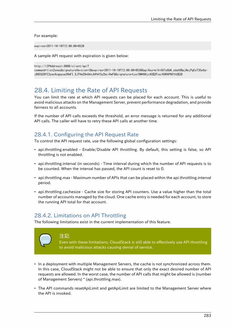
Limiting the Rate of API Requests
283
For example:
expires=2011-10-10T12:00:00+0530
A sample API request with expiration is given below:
http://<IPAddress>:8080/client/api?command=listZones&signatureVersion=3&expires=2011-10-10T12:00:00+0530&apiKey=miVr6X7u6bN_sdahOBpjNejPgEsT35eXq-jB8CG20YI3yaxXcgpyuaIRmFI_EJTVwZ0nUkkJbPmY3y2bciKwFQ&signature=Lxx1DM40AjcXU%2FcaiK8RAP0O1hU%3D
28.4. Limiting the Rate of API RequestsYou can limit the rate at which API requests can be placed for each account. This is useful toavoid malicious attacks on the Management Server, prevent performance degradation, and providefairness to all accounts.
If the number of API calls exceeds the threshold, an error message is returned for any additionalAPI calls. The caller will have to retry these API calls at another time.
28.4.1. Configuring the API Request RateTo control the API request rate, use the following global configuration settings:
• api.throttling.enabled - Enable/Disable API throttling. By default, this setting is false, so APIthrottling is not enabled.
• api.throttling.interval (in seconds) - Time interval during which the number of API requests is tobe counted. When the interval has passed, the API count is reset to 0.
• api.throttling.max - Maximum number of APIs that can be placed within the api.throttling.intervalperiod.
• api.throttling.cachesize - Cache size for storing API counters. Use a value higher than the totalnumber of accounts managed by the cloud. One cache entry is needed for each account, to storethe running API total for that account.
28.4.2. Limitations on API ThrottlingThe following limitations exist in the current implementation of this feature.
注記Even with these limitations, CloudStack is still able to effectively use API throttlingto avoid malicious attacks causing denial of service.
• In a deployment with multiple Management Servers, the cache is not synchronized across them.In this case, CloudStack might not be able to ensure that only the exact desired number of APIrequests are allowed. In the worst case, the number of API calls that might be allowed is (numberof Management Servers) * (api.throttling.max).
• The API commands resetApiLimit and getApiLimit are limited to the Management Server wherethe API is invoked.
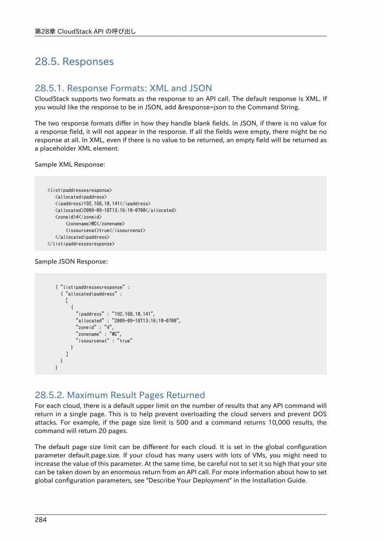
第28章 CloudStack API の呼び出し
284
28.5. Responses
28.5.1. Response Formats: XML and JSONCloudStack supports two formats as the response to an API call. The default response is XML. Ifyou would like the response to be in JSON, add &response=json to the Command String.
The two response formats differ in how they handle blank fields. In JSON, if there is no value fora response field, it will not appear in the response. If all the fields were empty, there might be noresponse at all. In XML, even if there is no value to be returned, an empty field will be returned asa placeholder XML element.
Sample XML Response:
<listipaddressesresponse> <allocatedipaddress> <ipaddress>192.168.10.141</ipaddress> <allocated>2009-09-18T13:16:10-0700</allocated> <zoneid>4</zoneid> <zonename>WC</zonename> <issourcenat>true</issourcenat> </allocatedipaddress> </listipaddressesresponse>
Sample JSON Response:
{ "listipaddressesresponse" : { "allocatedipaddress" : [ { "ipaddress" : "192.168.10.141", "allocated" : "2009-09-18T13:16:10-0700", "zoneid" : "4", "zonename" : "WC", "issourcenat" : "true" } ] } }
28.5.2. Maximum Result Pages ReturnedFor each cloud, there is a default upper limit on the number of results that any API command willreturn in a single page. This is to help prevent overloading the cloud servers and prevent DOSattacks. For example, if the page size limit is 500 and a command returns 10,000 results, thecommand will return 20 pages.
The default page size limit can be different for each cloud. It is set in the global configurationparameter default.page.size. If your cloud has many users with lots of VMs, you might need toincrease the value of this parameter. At the same time, be careful not to set it so high that your sitecan be taken down by an enormous return from an API call. For more information about how to setglobal configuration parameters, see "Describe Your Deployment" in the Installation Guide.
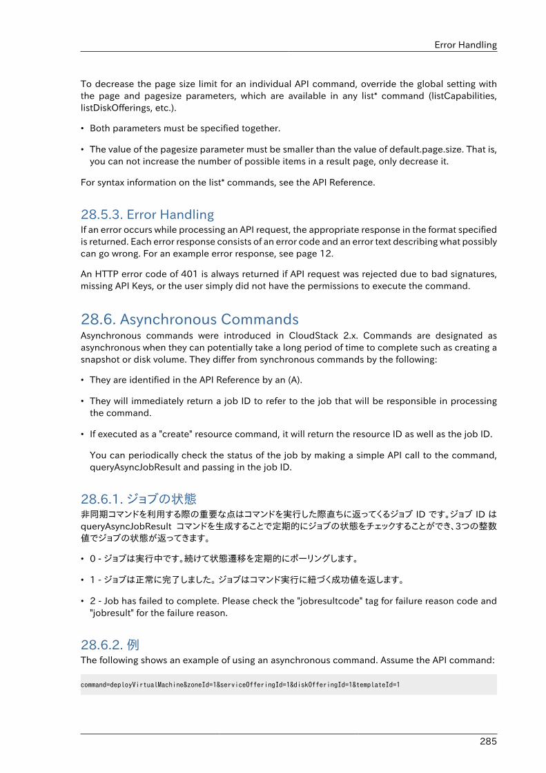
Error Handling
285
To decrease the page size limit for an individual API command, override the global setting withthe page and pagesize parameters, which are available in any list* command (listCapabilities,listDiskOfferings, etc.).
• Both parameters must be specified together.
• The value of the pagesize parameter must be smaller than the value of default.page.size. That is,you can not increase the number of possible items in a result page, only decrease it.
For syntax information on the list* commands, see the API Reference.
28.5.3. Error HandlingIf an error occurs while processing an API request, the appropriate response in the format specifiedis returned. Each error response consists of an error code and an error text describing what possiblycan go wrong. For an example error response, see page 12.
An HTTP error code of 401 is always returned if API request was rejected due to bad signatures,missing API Keys, or the user simply did not have the permissions to execute the command.
28.6. Asynchronous CommandsAsynchronous commands were introduced in CloudStack 2.x. Commands are designated asasynchronous when they can potentially take a long period of time to complete such as creating asnapshot or disk volume. They differ from synchronous commands by the following:
• They are identified in the API Reference by an (A).
• They will immediately return a job ID to refer to the job that will be responsible in processingthe command.
• If executed as a "create" resource command, it will return the resource ID as well as the job ID.
You can periodically check the status of the job by making a simple API call to the command,queryAsyncJobResult and passing in the job ID.
28.6.1. ジョブの状態非同期コマンドを利用する際の重要な点はコマンドを実行した際直ちに返ってくるジョブ ID です。ジョブ ID はqueryAsyncJobResult コマンドを生成することで定期的にジョブの状態をチェックすることができ、3つの整数値でジョブの状態が返ってきます。
• 0 - ジョブは実行中です。続けて状態遷移を定期的にポーリングします。
• 1 - ジョブは正常に完了しました。 ジョブはコマンド実行に紐づく成功値を返します。
• 2 - Job has failed to complete. Please check the "jobresultcode" tag for failure reason code and"jobresult" for the failure reason.
28.6.2. 例The following shows an example of using an asynchronous command. Assume the API command:
command=deployVirtualMachine&zoneId=1&serviceOfferingId=1&diskOfferingId=1&templateId=1
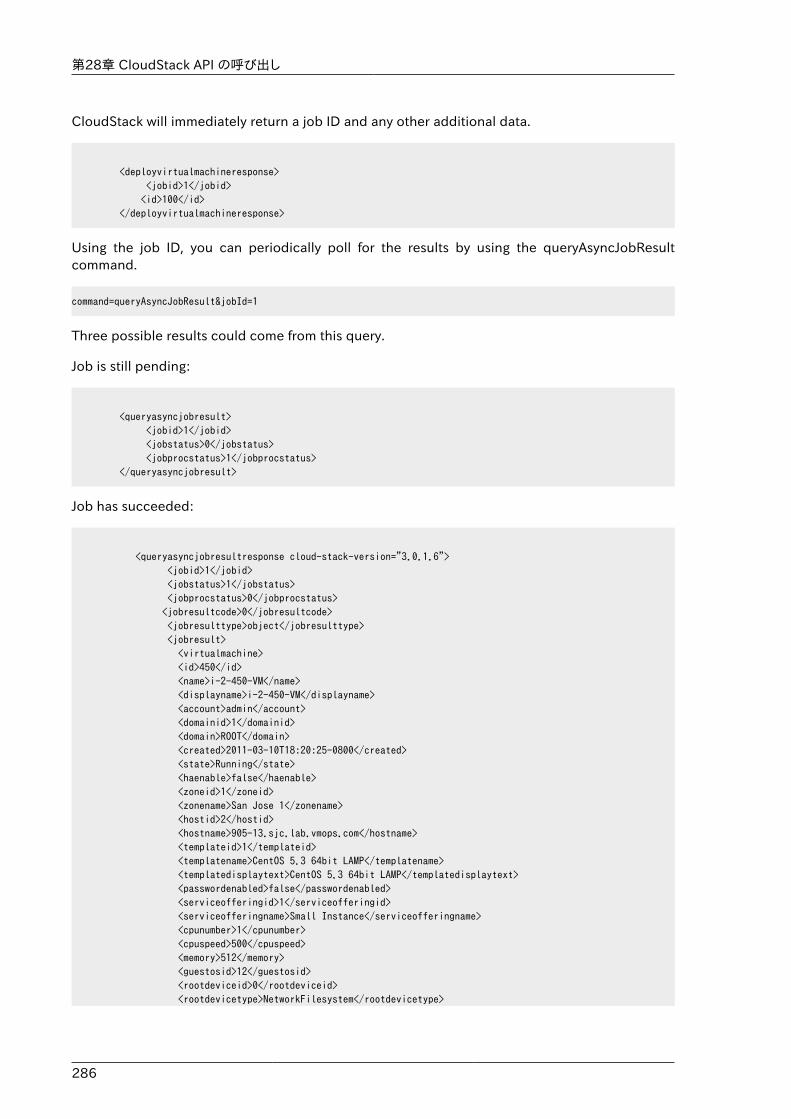
第28章 CloudStack API の呼び出し
286
CloudStack will immediately return a job ID and any other additional data.
<deployvirtualmachineresponse> <jobid>1</jobid> <id>100</id> </deployvirtualmachineresponse>
Using the job ID, you can periodically poll for the results by using the queryAsyncJobResultcommand.
command=queryAsyncJobResult&jobId=1
Three possible results could come from this query.
Job is still pending:
<queryasyncjobresult> <jobid>1</jobid> <jobstatus>0</jobstatus> <jobprocstatus>1</jobprocstatus> </queryasyncjobresult>
Job has succeeded:
<queryasyncjobresultresponse cloud-stack-version="3.0.1.6"> <jobid>1</jobid> <jobstatus>1</jobstatus> <jobprocstatus>0</jobprocstatus> <jobresultcode>0</jobresultcode> <jobresulttype>object</jobresulttype> <jobresult> <virtualmachine> <id>450</id> <name>i-2-450-VM</name> <displayname>i-2-450-VM</displayname> <account>admin</account> <domainid>1</domainid> <domain>ROOT</domain> <created>2011-03-10T18:20:25-0800</created> <state>Running</state> <haenable>false</haenable> <zoneid>1</zoneid> <zonename>San Jose 1</zonename> <hostid>2</hostid> <hostname>905-13.sjc.lab.vmops.com</hostname> <templateid>1</templateid> <templatename>CentOS 5.3 64bit LAMP</templatename> <templatedisplaytext>CentOS 5.3 64bit LAMP</templatedisplaytext> <passwordenabled>false</passwordenabled> <serviceofferingid>1</serviceofferingid> <serviceofferingname>Small Instance</serviceofferingname> <cpunumber>1</cpunumber> <cpuspeed>500</cpuspeed> <memory>512</memory> <guestosid>12</guestosid> <rootdeviceid>0</rootdeviceid> <rootdevicetype>NetworkFilesystem</rootdevicetype>
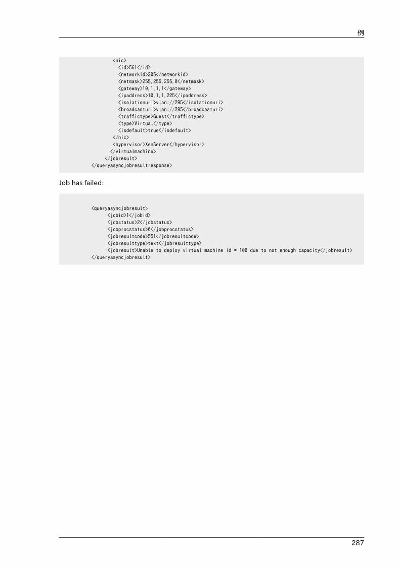
例
287
<nic> <id>561</id> <networkid>205</networkid> <netmask>255.255.255.0</netmask> <gateway>10.1.1.1</gateway> <ipaddress>10.1.1.225</ipaddress> <isolationuri>vlan://295</isolationuri> <broadcasturi>vlan://295</broadcasturi> <traffictype>Guest</traffictype> <type>Virtual</type> <isdefault>true</isdefault> </nic> <hypervisor>XenServer</hypervisor> </virtualmachine> </jobresult> </queryasyncjobresultresponse>
Job has failed:
<queryasyncjobresult> <jobid>1</jobid> <jobstatus>2</jobstatus> <jobprocstatus>0</jobprocstatus> <jobresultcode>551</jobresultcode> <jobresulttype>text</jobresulttype> <jobresult>Unable to deploy virtual machine id = 100 due to not enough capacity</jobresult> </queryasyncjobresult>

288
289
Working With Usage DataThe Usage Server provides aggregated usage records which you can use to create billing integrationfor the CloudStack platform. The Usage Server works by taking data from the events log and creatingsummary usage records that you can access using the listUsageRecords API call.
The usage records show the amount of resources, such as VM run time or template storage space,consumed by guest instances. In the special case of bare metal instances, no template storageresources are consumed, but records showing zero usage are still included in the Usage Server'soutput.
The Usage Server runs at least once per day. It can be configured to run multiple times per day.Its behavior is controlled by configuration settings as described in the CloudStack AdministrationGuide.
29.1. Usage Record Format
29.1.1. Virtual Machine Usage Record FormatFor running and allocated virtual machine usage, the following fields exist in a usage record:
• account – name of the account
• accountid – ID of the account
• domainid – ID of the domain in which this account resides
• zoneid – Zone where the usage occurred
• description – A string describing what the usage record is tracking
• usage – String representation of the usage, including the units of usage (e.g. 'Hrs' for VM runningtime)
• usagetype – A number representing the usage type (see Usage Types)
• rawusage – A number representing the actual usage in hours
• virtualMachineId – The ID of the virtual machine
• name – The name of the virtual machine
• offeringid – The ID of the service offering
• templateid – The ID of the template or the ID of the parent template. The parent template valueis present when the current template was created from a volume.
• usageid – Virtual machine
• type – Hypervisor
• startdate, enddate – The range of time for which the usage is aggregated; see Dates in the UsageRecord
第29章 Working With Usage Data
290
29.1.2. Network Usage Record FormatFor network usage (bytes sent/received), the following fields exist in a usage record.
• account – name of the account
• accountid – ID of the account
• domainid – ID of the domain in which this account resides
• zoneid – Zone where the usage occurred
• description – A string describing what the usage record is tracking
• usagetype – A number representing the usage type (see Usage Types)
• rawusage – A number representing the actual usage in hours
• usageid – Device ID (virtual router ID or external device ID)
• type – Device type (domain router, external load balancer, etc.)
• startdate, enddate – The range of time for which the usage is aggregated; see Dates in the UsageRecord
29.1.3. IP Address Usage Record FormatFor IP address usage the following fields exist in a usage record.
• account - name of the account
• accountid - ID of the account
• domainid - ID of the domain in which this account resides
• zoneid - Zone where the usage occurred
• description - A string describing what the usage record is tracking
• usage - String representation of the usage, including the units of usage
• usagetype - A number representing the usage type (see Usage Types)
• rawusage - A number representing the actual usage in hours
• usageid - IP address ID
• startdate, enddate - The range of time for which the usage is aggregated; see Dates in the UsageRecord
• issourcenat - Whether source NAT is enabled for the IP address
• iselastic - True if the IP address is elastic.
29.1.4. Disk Volume Usage Record FormatFor disk volumes, the following fields exist in a usage record.
Template, ISO, and Snapshot Usage Record Format
291
• account – name of the account
• accountid – ID of the account
• domainid – ID of the domain in which this account resides
• zoneid – Zone where the usage occurred
• description – A string describing what the usage record is tracking
• usage – String representation of the usage, including the units of usage (e.g. 'Hrs' for hours)
• usagetype – A number representing the usage type (see Usage Types)
• rawusage – A number representing the actual usage in hours
• usageid – The volume ID
• offeringid – The ID of the disk offering
• type – Hypervisor
• templateid – ROOT template ID
• size – The amount of storage allocated
• startdate, enddate – The range of time for which the usage is aggregated; see Dates in the UsageRecord
29.1.5. Template, ISO, and Snapshot Usage Record Format• account – name of the account
• accountid – ID of the account
• domainid – ID of the domain in which this account resides
• zoneid – Zone where the usage occurred
• description – A string describing what the usage record is tracking
• usage – String representation of the usage, including the units of usage (e.g. 'Hrs' for hours)
• usagetype – A number representing the usage type (see Usage Types)
• rawusage – A number representing the actual usage in hours
• usageid – The ID of the the template, ISO, or snapshot
• offeringid – The ID of the disk offering
• templateid – – Included only for templates (usage type 7). Source template ID.
• size – Size of the template, ISO, or snapshot
• startdate, enddate – The range of time for which the usage is aggregated; see Dates in the UsageRecord
第29章 Working With Usage Data
292
29.1.6. Load Balancer Policy or Port Forwarding Rule Usage RecordFormat• account - name of the account
• accountid - ID of the account
• domainid - ID of the domain in which this account resides
• zoneid - Zone where the usage occurred
• description - A string describing what the usage record is tracking
• usage - String representation of the usage, including the units of usage (e.g. 'Hrs' for hours)
• usagetype - A number representing the usage type (see Usage Types)
• rawusage - A number representing the actual usage in hours
• usageid - ID of the load balancer policy or port forwarding rule
• usagetype - A number representing the usage type (see Usage Types)
• startdate, enddate - The range of time for which the usage is aggregated; see Dates in the UsageRecord
29.1.7. Network Offering Usage Record Format• account – name of the account
• accountid – ID of the account
• domainid – ID of the domain in which this account resides
• zoneid – Zone where the usage occurred
• description – A string describing what the usage record is tracking
• usage – String representation of the usage, including the units of usage (e.g. 'Hrs' for hours)
• usagetype – A number representing the usage type (see Usage Types)
• rawusage – A number representing the actual usage in hours
• usageid – ID of the network offering
• usagetype – A number representing the usage type (see Usage Types)
• offeringid – Network offering ID
• virtualMachineId – The ID of the virtual machine
• virtualMachineId – The ID of the virtual machine
• startdate, enddate – The range of time for which the usage is aggregated; see Dates in the UsageRecord
VPN User Usage Record Format
293
29.1.8. VPN User Usage Record Format• account – name of the account
• accountid – ID of the account
• domainid – ID of the domain in which this account resides
• zoneid – Zone where the usage occurred
• description – A string describing what the usage record is tracking
• usage – String representation of the usage, including the units of usage (e.g. 'Hrs' for hours)
• usagetype – A number representing the usage type (see Usage Types)
• rawusage – A number representing the actual usage in hours
• usageid – VPN user ID
• usagetype – A number representing the usage type (see Usage Types)
• startdate, enddate – The range of time for which the usage is aggregated; see Dates in the UsageRecord
29.2. 使用状況データの種類次の表は使用状況データの種類を表しています。
Type ID Type Name 説明
1 RUNNING_VM 使用状況レコードの期間における仮想マシンの総稼働時間を追跡します。もし期間中に仮想マシンがアップグレードされた場合は、新しいアップグレードされた仮想マシンに対し別の使用状況レコードを取得します。
2 ALLOCATED_VM 仮想マシンが作成されてから削除されるまでの総時間を追跡します。この使用状況タイプはWindows ベースのテンプレートのような特定テンプレートの使用状況を確認するのに役立ちます。
3 IP_ADDRESS アカウントが所有するパブリックIP を追跡します
4 NETWORK_BYTES_SENT アカウントが所有している全ての仮想マシンから送信したデータの総バイト数を追跡します。Cloud.com は 現在仮想マシン毎のネットワークトラフィックは追跡しません。
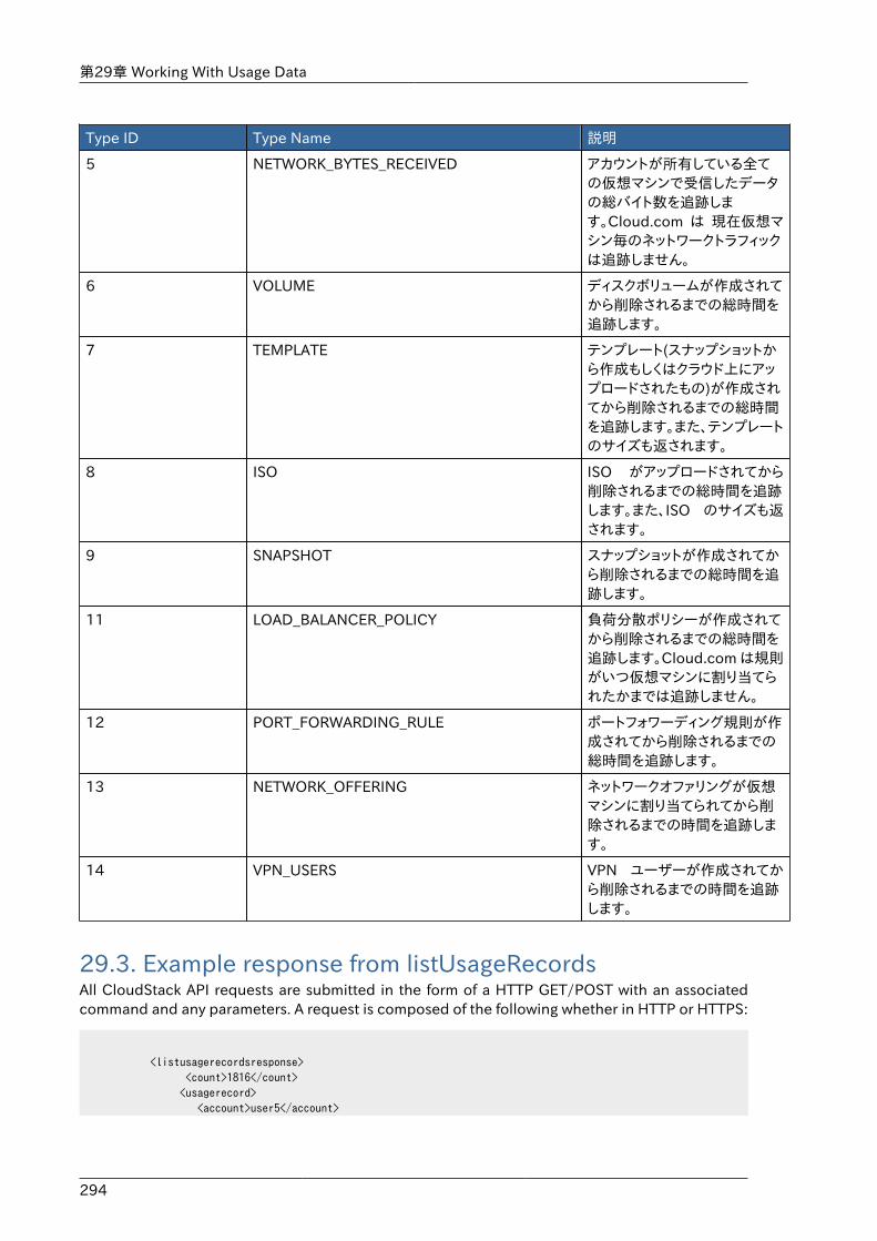
第29章 Working With Usage Data
294
Type ID Type Name 説明
5 NETWORK_BYTES_RECEIVED アカウントが所有している全ての仮想マシンで受信したデータの総バイト数を追跡します。Cloud.com は 現在仮想マシン毎のネットワークトラフィックは追跡しません。
6 VOLUME ディスクボリュームが作成されてから削除されるまでの総時間を追跡します。
7 TEMPLATE テンプレート(スナップショットから作成もしくはクラウド上にアップロードされたもの)が作成されてから削除されるまでの総時間を追跡します。また、テンプレートのサイズも返されます。
8 ISO ISO がアップロードされてから削除されるまでの総時間を追跡します。また、ISO のサイズも返されます。
9 SNAPSHOT スナップショットが作成されてから削除されるまでの総時間を追跡します。
11 LOAD_BALANCER_POLICY 負荷分散ポリシーが作成されてから削除されるまでの総時間を追跡します。Cloud.com は規則がいつ仮想マシンに割り当てられたかまでは追跡しません。
12 PORT_FORWARDING_RULE ポートフォワーディング規則が作成されてから削除されるまでの総時間を追跡します。
13 NETWORK_OFFERING ネットワークオファリングが仮想マシンに割り当てられてから削除されるまでの時間を追跡します。
14 VPN_USERS VPN ユーザーが作成されてから削除されるまでの時間を追跡します。
29.3. Example response from listUsageRecordsAll CloudStack API requests are submitted in the form of a HTTP GET/POST with an associatedcommand and any parameters. A request is composed of the following whether in HTTP or HTTPS:
<listusagerecordsresponse> <count>1816</count> <usagerecord> <account>user5</account>
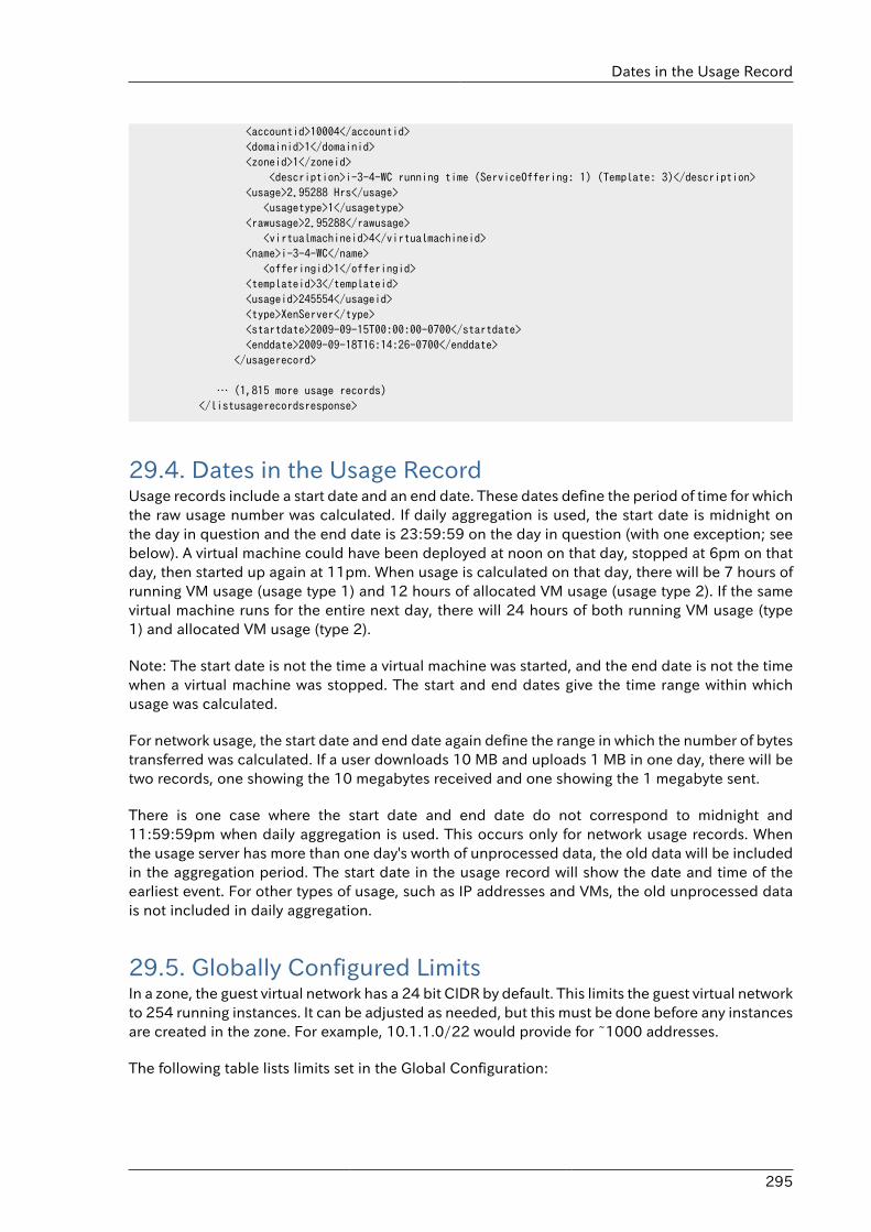
Dates in the Usage Record
295
<accountid>10004</accountid> <domainid>1</domainid> <zoneid>1</zoneid> <description>i-3-4-WC running time (ServiceOffering: 1) (Template: 3)</description> <usage>2.95288 Hrs</usage> <usagetype>1</usagetype> <rawusage>2.95288</rawusage> <virtualmachineid>4</virtualmachineid> <name>i-3-4-WC</name> <offeringid>1</offeringid> <templateid>3</templateid> <usageid>245554</usageid> <type>XenServer</type> <startdate>2009-09-15T00:00:00-0700</startdate> <enddate>2009-09-18T16:14:26-0700</enddate> </usagerecord>
… (1,815 more usage records) </listusagerecordsresponse>
29.4. Dates in the Usage RecordUsage records include a start date and an end date. These dates define the period of time for whichthe raw usage number was calculated. If daily aggregation is used, the start date is midnight onthe day in question and the end date is 23:59:59 on the day in question (with one exception; seebelow). A virtual machine could have been deployed at noon on that day, stopped at 6pm on thatday, then started up again at 11pm. When usage is calculated on that day, there will be 7 hours ofrunning VM usage (usage type 1) and 12 hours of allocated VM usage (usage type 2). If the samevirtual machine runs for the entire next day, there will 24 hours of both running VM usage (type1) and allocated VM usage (type 2).
Note: The start date is not the time a virtual machine was started, and the end date is not the timewhen a virtual machine was stopped. The start and end dates give the time range within whichusage was calculated.
For network usage, the start date and end date again define the range in which the number of bytestransferred was calculated. If a user downloads 10 MB and uploads 1 MB in one day, there will betwo records, one showing the 10 megabytes received and one showing the 1 megabyte sent.
There is one case where the start date and end date do not correspond to midnight and11:59:59pm when daily aggregation is used. This occurs only for network usage records. Whenthe usage server has more than one day's worth of unprocessed data, the old data will be includedin the aggregation period. The start date in the usage record will show the date and time of theearliest event. For other types of usage, such as IP addresses and VMs, the old unprocessed datais not included in daily aggregation.
29.5. Globally Configured LimitsIn a zone, the guest virtual network has a 24 bit CIDR by default. This limits the guest virtual networkto 254 running instances. It can be adjusted as needed, but this must be done before any instancesare created in the zone. For example, 10.1.1.0/22 would provide for ~1000 addresses.
The following table lists limits set in the Global Configuration:
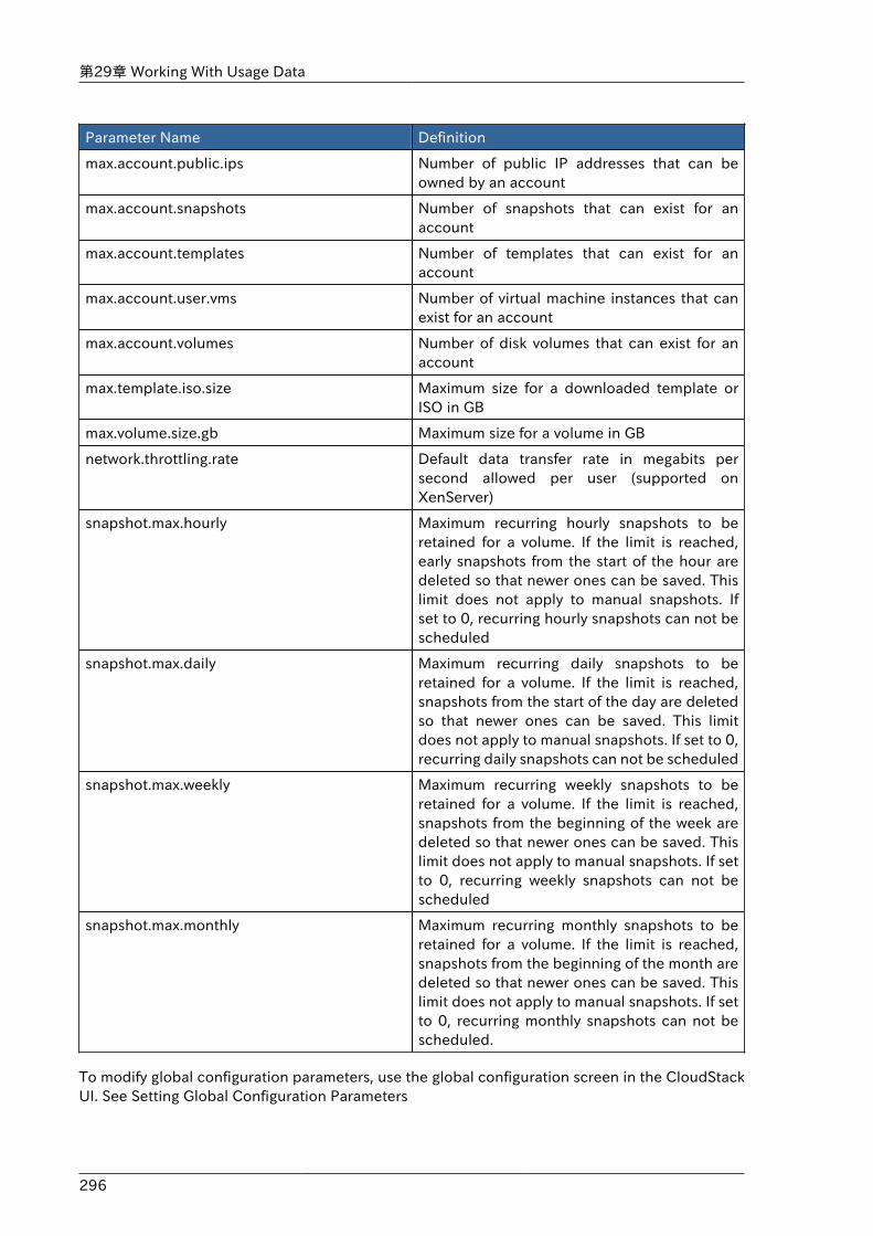
第29章 Working With Usage Data
296
Parameter Name Definition
max.account.public.ips Number of public IP addresses that can beowned by an account
max.account.snapshots Number of snapshots that can exist for anaccount
max.account.templates Number of templates that can exist for anaccount
max.account.user.vms Number of virtual machine instances that canexist for an account
max.account.volumes Number of disk volumes that can exist for anaccount
max.template.iso.size Maximum size for a downloaded template orISO in GB
max.volume.size.gb Maximum size for a volume in GB
network.throttling.rate Default data transfer rate in megabits persecond allowed per user (supported onXenServer)
snapshot.max.hourly Maximum recurring hourly snapshots to beretained for a volume. If the limit is reached,early snapshots from the start of the hour aredeleted so that newer ones can be saved. Thislimit does not apply to manual snapshots. Ifset to 0, recurring hourly snapshots can not bescheduled
snapshot.max.daily Maximum recurring daily snapshots to beretained for a volume. If the limit is reached,snapshots from the start of the day are deletedso that newer ones can be saved. This limitdoes not apply to manual snapshots. If set to 0,recurring daily snapshots can not be scheduled
snapshot.max.weekly Maximum recurring weekly snapshots to beretained for a volume. If the limit is reached,snapshots from the beginning of the week aredeleted so that newer ones can be saved. Thislimit does not apply to manual snapshots. If setto 0, recurring weekly snapshots can not bescheduled
snapshot.max.monthly Maximum recurring monthly snapshots to beretained for a volume. If the limit is reached,snapshots from the beginning of the month aredeleted so that newer ones can be saved. Thislimit does not apply to manual snapshots. If setto 0, recurring monthly snapshots can not bescheduled.
To modify global configuration parameters, use the global configuration screen in the CloudStackUI. See Setting Global Configuration Parameters

297
付録A タイムゾーンCloudStack では、次のタイムゾーン識別子を使用できます。設定の一部で、必須またはオプションのパラメーターとしてタイムゾー ンを使用します。これには、構成テーブルにおける、定期スナップショットのスケジュール、ユーザーの作成、および使用タイムゾーンの指定が含まれます。
Etc/GMT+12 Etc/GMT+11 Pacific/Samoa
Pacific/Honolulu US/Alaska America/Los_Angeles
Mexico/BajaNorte US/Arizona US/Mountain
America/Chihuahua America/Chicago America/Costa_Rica
America/Mexico_City Canada/Saskatchewan America/Bogota
America/New_York America/Caracas America/Asuncion
America/Cuiaba America/Halifax America/La_Paz
America/Santiago America/St_Johns America/Araguaina
America/Argentina/Buenos_Aires
America/Cayenne America/Godthab
America/Montevideo Etc/GMT+2 Atlantic/Azores
Atlantic/Cape_Verde Africa/Casablanca Etc/UTC
Atlantic/Reykjavik Europe/London CET
Europe/Bucharest Africa/Johannesburg Asia/Beirut
Africa/Cairo Asia/Jerusalem Europe/Minsk
Europe/Moscow Africa/Nairobi Asia/Karachi
Asia/Kolkata Asia/Bangkok Asia/Shanghai
Asia/Kuala_Lumpur Australia/Perth Asia/Taipei
Asia/Tokyo Asia/Seoul Australia/Adelaide
Australia/Darwin Australia/Brisbane Australia/Canberra
Pacific/Guam Pacific/Auckland

298
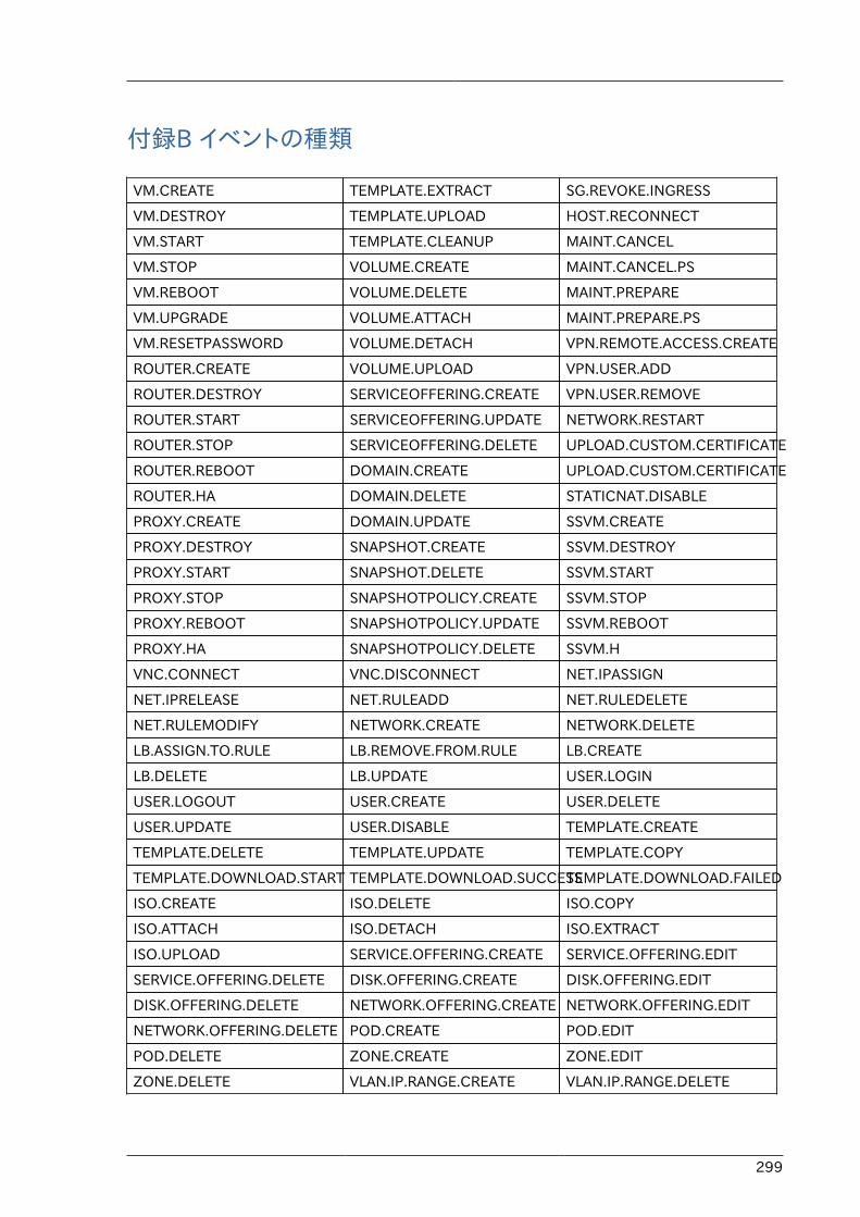
299
付録B イベントの種類
VM.CREATE TEMPLATE.EXTRACT SG.REVOKE.INGRESS
VM.DESTROY TEMPLATE.UPLOAD HOST.RECONNECT
VM.START TEMPLATE.CLEANUP MAINT.CANCEL
VM.STOP VOLUME.CREATE MAINT.CANCEL.PS
VM.REBOOT VOLUME.DELETE MAINT.PREPARE
VM.UPGRADE VOLUME.ATTACH MAINT.PREPARE.PS
VM.RESETPASSWORD VOLUME.DETACH VPN.REMOTE.ACCESS.CREATE
ROUTER.CREATE VOLUME.UPLOAD VPN.USER.ADD
ROUTER.DESTROY SERVICEOFFERING.CREATE VPN.USER.REMOVE
ROUTER.START SERVICEOFFERING.UPDATE NETWORK.RESTART
ROUTER.STOP SERVICEOFFERING.DELETE UPLOAD.CUSTOM.CERTIFICATE
ROUTER.REBOOT DOMAIN.CREATE UPLOAD.CUSTOM.CERTIFICATE
ROUTER.HA DOMAIN.DELETE STATICNAT.DISABLE
PROXY.CREATE DOMAIN.UPDATE SSVM.CREATE
PROXY.DESTROY SNAPSHOT.CREATE SSVM.DESTROY
PROXY.START SNAPSHOT.DELETE SSVM.START
PROXY.STOP SNAPSHOTPOLICY.CREATE SSVM.STOP
PROXY.REBOOT SNAPSHOTPOLICY.UPDATE SSVM.REBOOT
PROXY.HA SNAPSHOTPOLICY.DELETE SSVM.H
VNC.CONNECT VNC.DISCONNECT NET.IPASSIGN
NET.IPRELEASE NET.RULEADD NET.RULEDELETE
NET.RULEMODIFY NETWORK.CREATE NETWORK.DELETE
LB.ASSIGN.TO.RULE LB.REMOVE.FROM.RULE LB.CREATE
LB.DELETE LB.UPDATE USER.LOGIN
USER.LOGOUT USER.CREATE USER.DELETE
USER.UPDATE USER.DISABLE TEMPLATE.CREATE
TEMPLATE.DELETE TEMPLATE.UPDATE TEMPLATE.COPY
TEMPLATE.DOWNLOAD.START TEMPLATE.DOWNLOAD.SUCCESSTEMPLATE.DOWNLOAD.FAILED
ISO.CREATE ISO.DELETE ISO.COPY
ISO.ATTACH ISO.DETACH ISO.EXTRACT
ISO.UPLOAD SERVICE.OFFERING.CREATE SERVICE.OFFERING.EDIT
SERVICE.OFFERING.DELETE DISK.OFFERING.CREATE DISK.OFFERING.EDIT
DISK.OFFERING.DELETE NETWORK.OFFERING.CREATE NETWORK.OFFERING.EDIT
NETWORK.OFFERING.DELETE POD.CREATE POD.EDIT
POD.DELETE ZONE.CREATE ZONE.EDIT
ZONE.DELETE VLAN.IP.RANGE.CREATE VLAN.IP.RANGE.DELETE

付録B イベントの種類
300
CONFIGURATION.VALUE.EDIT SG.AUTH.INGRESS
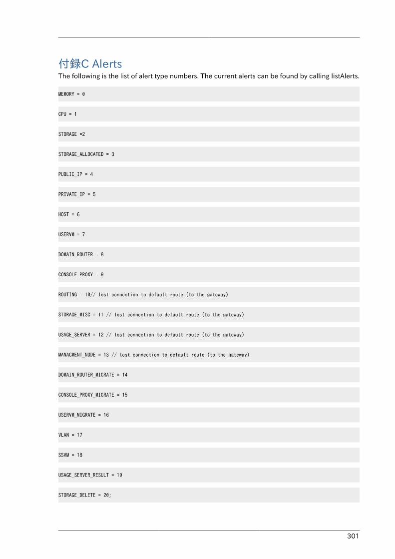
301
付録C AlertsThe following is the list of alert type numbers. The current alerts can be found by calling listAlerts.
MEMORY = 0
CPU = 1
STORAGE =2
STORAGE_ALLOCATED = 3
PUBLIC_IP = 4
PRIVATE_IP = 5
HOST = 6
USERVM = 7
DOMAIN_ROUTER = 8
CONSOLE_PROXY = 9
ROUTING = 10// lost connection to default route (to the gateway)
STORAGE_MISC = 11 // lost connection to default route (to the gateway)
USAGE_SERVER = 12 // lost connection to default route (to the gateway)
MANAGMENT_NODE = 13 // lost connection to default route (to the gateway)
DOMAIN_ROUTER_MIGRATE = 14
CONSOLE_PROXY_MIGRATE = 15
USERVM_MIGRATE = 16
VLAN = 17
SSVM = 18
USAGE_SERVER_RESULT = 19
STORAGE_DELETE = 20;
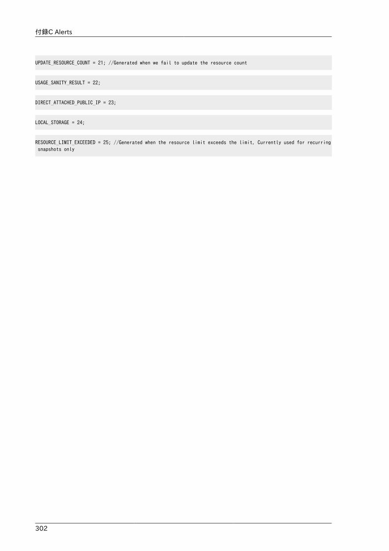
付録C Alerts
302
UPDATE_RESOURCE_COUNT = 21; //Generated when we fail to update the resource count
USAGE_SANITY_RESULT = 22;
DIRECT_ATTACHED_PUBLIC_IP = 23;
LOCAL_STORAGE = 24;
RESOURCE_LIMIT_EXCEEDED = 25; //Generated when the resource limit exceeds the limit. Currently used for recurring snapshots only