clp a technology for the in teractive...
TRANSCRIPT

ITcon Vol. 11 (2006), Calderon et al, pg. 325
CLP A TECHNOLOGY FOR THE INTERACTIVE RESOLUTION OF SPATIAL CONFIGURATION TASKS IN A VIRTUAL ENVIRONMENT
SUBMITTED: July 2005 REVISED: November 2005 PUBLISHED: May 2006 at http://itcon.org/2006/24/ EDITOR: J. M. Kamara
Carlos Calderón School of Architecture, Planning and Landscape, University of Newcastle, UK email: [email protected]
Marc Cavazza School of Computing, University of Teesside, UK email: [email protected]
Daniel Diaz University of Paris, France email: [email protected]
SUMMARY: In this paper, we present a new framework for the use of Virtual Reality (VR) in engineering design for configuration applications that, while preserving the natural interaction of traditional VR Systems, support the expression of design knowledge in the Virtual Environment (VE) and the visualisation of the user’s interactions with the configuration. Traditional VR systems support the visual exploration of a design solution but do not assist the user in exploring alternative solutions based on domain knowledge. Extending previous work in the area of Intelligent Virtual Environments (IVEs), we propose an intelligent configuration system based on constraint logic programming (CLP), integrated in a real-time 3D graphic environment. This type of integration facilitates the expression of design knowledge in the VE and enables the user to interactively solve and/or refine a spatial configuration problem. Consequently and in order to demonstrate the viability of our approach, we have implemented an intelligent configuration system in which the user can visually explore configurations, but his interaction with objects of the configuration problem triggers new cycles of constraint propagation from the modified configuration to produce a new compatible solution.
KEYWORDS: virtual environments, artificial intelligence, constraint logic programming, spatial configuration tasks.
1. INTRODUCTION Spatial configuration problems are visual by nature and they are based on an implicit mapping between the “abstract problem space” (which is searched for solution configurations) and the physical environment in which these configurations are deployed. It is, however, difficult to make this implicit mapping transparent to the user. VR techniques have the potential to solve this problem but, in the current use of VR for engineering design, the knowledge is mainly expressed on the geometrical layout, textures, colours, etc. As a result of this, VR assistance in the use of the underlying design knowledge is restricted. To put it differently, it is currently not feasible to attach much design knowledge to the VE; consequently, users cannot use the “natural” interaction mechanisms of VR to interact with it and visualise the “dynamic” consequences of their interactions with the configuration.
In this paper, we present IVEs as a new approach for the use of Virtual Reality in spatial configuration problems in building design. This approach preserves the nature of VR in terms of interactive and active exploration but supports the expression of design knowledge in the VE and, therefore, by taking advantage of the interactive nature of VR, the user can interact with the semantics attached to the VE (e.g. design knowledge). In the context of configuration applications this translates into the user being able to navigate and physically interact with 3D objects, but this interaction triggers the automatic reconfiguration of the configuration problem (based on the design knowledge expressed in the VE) and thus, allowing the dynamic exploration of design solutions.
We claim that this can be achieved by integrating Constraint Logic Programming (CLP) techniques into Virtual
ITcon Vol. 11 (2006), Calderon et al, pg. 326
Environments, extending previous work in IVEs (Axling et al, 1996) (Aylett and Cavazza, 2001). Consequently and in order to demonstrate the viability of our approach, we have implemented an intelligent configuration system in which solutions can be interactively refined by the user through direct manipulation of objects in the virtual environment. The intelligent configuration system utilises basic interaction mechanisms to illustrate how the proposed technique and methodology used for expression and formalisation of design knowledge enhanced a VE so that the underlying design knowledge embedded in the VE can be used to interactively produce design solutions.
In the following sections, after reviewing the background related work, we present a conceptual framework to illustrate the applicability of the work in the building design domain. We then, using an intelligent configuration system as an example, discuss the formalisation of design knowledge in CLP, its expression in the VE and the interactive exploration of solutions. We conclude by discussing how our results address the difficult technical challenges of reactive planning and drawing some conclusions.
2. BACKGROUND Spatial configuration problems constitute an important class of applications for Virtual Reality techniques in building design. For instance, one of the most successful applications of VR has been in the area of interior design and architecture where spatial configuration problems are paramount. However, in “traditional” VR the knowledge is mainly expressed on the geometrical layout, textures, colours, etc. As a result of this, VR assistance in the use of the underlying design knowledge to interactively produce design solutions is restricted. Consequently, there is a need to develop techniques and methodologies which integrate the generation of solutions into the visual exploration and interaction capabilities of the virtual environments, thus making the generation of solutions interactive per se. This type of integration is based on an implicit mapping between the “abstract problem space”, which is searched for solutions configurations, and the physical/visual environment in which these configurations are deployed. Consequently, this new generation of VR systems based on IVEs aims at being fully interactive.
This full interactivity can be seen from two different standpoints: (i) as an extension of the current interactivity offered by VR systems, in which, seen from the user’s perspective, the environment automatically reconfigures itself as a consequence of his/her interactions and therefore, the system generates an alternative solution(s) as a result of the user’s interaction; (ii) as a visual interface to interactive problem solving mechanisms. Therefore, a fully interactive environment provides a transparent interface and natural interaction mechanisms to the “abstract problem space” in which the solution to the spatial configuration problem can be found.
The technical challenges, for the implementation of a fully interactive virtual environment, lie in keeping the user-centred aspects of virtual reality: exploration and interaction in a 3D real-time computer generated environment. In other words, the challenge consists in making the search for solutions interactive whilst maintaining the nature of VR so that the VE can be used as an interface to explore the configuration and its “abstract problem space” in which a solution, if it exists, can be found.
2.1 Technical challenges IVEs’ rationale is the integration of symbolic reasoning techniques into a virtual environment to support intelligent behaviour. This integrated approach faces a number of technical problems. On the one hand, an appropriate knowledge representation scheme or framework is needed to express the design knowledge. That is, a knowledge representation scheme (i.e. rule-based, constraint satisfaction, etc) and a formalism (i.e. constraint logic programming) where the application domain knowledge can be easily expressed and represented in the system independently of the problem-solving mechanisms used (i.e. breadth first search). However, for the development of an IVE which supports the resolution of spatial configuration problems there is a further and critical requirement for the knowledge representation and the formalism used to encode that knowledge: they must maintain the principles of VR the user-centred perspective. In other words, it is commonly found in configuration problems that the location of different objects is related to each other as well as the topological conditions in the environment. This can prove quite difficult to implement using “traditional” methods especially when the number of objects is large and the topological restrictions are numerous due to the NP-hard (computationally intractable) nature of configuration problems. Therefore, a key aspect for the selection of the knowledge and representation formalism is that the implemented solving mechanisms must be compatible with the sampling rate, not so much of the visualisation (or frame rate), but in terms of the user interaction with the virtual world objects.

ITcon Vol. 11 (2006), Calderon et al, pg. 327
In order to maintain the user-centred aspects of a VR system, the performance prerequisites are twofold: (i) visual display, the requirement on the display frame rate of the environment required to provide the effects of immersion and presence; and (ii) the interactivity, the requirement on the latency time from when the user provides an input to when the system provides a response (visual or otherwise) required for the user to have useful control over objects in the environment (Bryson et at, 1995) Since it is not possible to predict all user actions and to store all corresponding frames in memory, the world has to be created and deleted in real-time. Additionally, human factors studies indicate that eye motion degrades “dramatically” under 12 frames/sec. Therefore, according to Burdea and Coiffet (Burdea and Coiffet, 1994), a smooth simulation requires at least 24 or better 30 frames/sec to be displayed. Consequently, the virtual world has a lifecycle (or visual display constraint) of only 33 msec.
The concept of interactivity is at the heart of Virtual Reality paradigm. In this instance, the interactivity is seen from the Human-in-the-loop perspective in which the user’s interaction is integrated in the system and occurs without distortion or with an acceptable latency. Latency, therefore, is a critical factor for interactivity in VR systems. The total simulation latency (the time between user’s action and VR system’s feedback) is the sum of the effects of sensor latency, transmission delays (to and from the VR engine) plus the time it takes to re-compute and display a new frame. As a result of their experimental results, Burdea and Coiffet (Burdea and Coiffet, 1994) have stated that if the total latency is over 150 msec, then the simulation quality degrades significantly and may even result in user dizziness and sickness, especially in immersive systems. Table 1 summarizes the technical challenges to maintain the user-centred aspects of a VR system.
TABLE 1: VR technical requirements Far Value Frame rate per second >= 30 fps Total latency =<150 mscs
2.2 Approaches to Virtual Design In the field of virtual design, previous work has described the inclusion of a knowledge level for design applications (Nomura et al, 1992). In these systems, a Decision Support Systems was added to the virtual environment to validate the design configurations. However, this type of system validates configurations, more as a diagnostic system, rather than enabling the user the visualisation of his interactions with the configuration by, i.e., reconfiguring the configuration. In addition, standard decision support systems, such as rule-based systems, lack flexibility in their inference mechanisms, which prevents their use in a fully interactive system.
Fernando et al. (Fernando et al, 1999), (Fa et al, 1993) have emphasised the importance of constraints in virtual design. However, they have been essentially dealing with graph-based techniques which do not support the interactive generation of alternative design solutions. In other words, graph-based techniques help to interactively find a solution by restricting the solution space but they are limited in terms of the generation of design alternatives once a solution has been found.
The use of constraint programming for the expression of construction knowledge was pioneered by the SEED (Software Environment for Support the Early Phases in Building Design) project at CMU (Fleming et al, 1994). The SEED project introduced the conceptual basis for the representation of constraints to automatically generate layouts and argued that constraint programming provides a uniform mechanism to handle the domain related knowledge, because spatial configurations could be naturally expressed as constraints. Moreover, constraints have proven to be a useful format to express engineering design knowledge (Lottaz et al, 1999). For instance, much engineering knowledge is stated in terms of constraints: regulations, codes of practice, behaviour models, cost restrictions, and planning strategies all employ explicit declaration of constraints which are easily translated into the “formal” constraints expression of constraint programming. Hence, constraint-based systems have the potential to be one of the most understandable and easiest to maintain of all reasoning systems.
Furthermore, previous research in the area of Intelligent Virtual Environments has proposed the use of constraint logic programming as a supporting mechanism for intelligent object behaviour, its rationale being the seamless integration of symbolic reasoning techniques with the visual and interaction components: Axling et al. (Axling et al, 1996) and Codognet (Codognet, 1999). Both Axling and Codognet have put emphasis on the behaviour of individual objects in the virtual world. However, CLP naturally provides solutions for the combined behaviours for sets of objects, which is the property we use to implement behaviours for the virtual environment as a whole.

ITcon Vol. 11 (2006), Calderon et al, pg. 328
3. CONCEPTUAL FRAMEWORK The objective of this section is to provide a framework and understanding of the fundamental relationships between concepts and therefore, to illustrate the applicability of the work in the building design domain. This section argues that, in order to implement a fully interactive VR system, the problem knowledge representation scheme, the programming framework, the representation formalism and the underlying problem-solving mechanisms cannot be viewed independently.
Constraint Satisfaction (CS), an Artificial Intelligence (AI) paradigm, is proposed as a knowledge representation for spatial configuration tasks. Constraint programming (CP) is put forward as a conceptual programming framework because it takes advantage of the properties which constraints naturally enjoy. These are vital to support the concept of a fully interactive virtual environment. Constraint Logic Programming (CLP) is selected as the most appropriate formalism to express constraint satisfaction problems. The selection of GNU-Prolog, a Constraint Logic Language over Finite Domains (CLP(FD)), as the implementation language is explained on the basis of its built-in predicates, its problem-solving mechanisms and its use of Finite Domains variables as a semantic structure.
3.1 Knowledge acquisition: building design requirements Knowledge acquisition refers to the collection of analysis of information from one or more sources leading to acquire and encapsulate knowledge (Jackson, 1999).
There are many theoretical models that could be used to describe the conceptual basis for the representation of building design requirements (Kamara, 1999) (Fleming et al, 1994) (Rivard, 1997). In this investigation, the framework adopted follows Lawson’s model (Lawson, 1997) to explain the generation of design requirements (sources of knowledge) and the SEED (Software Environment for Support the Early Phases in Building Design) model (Fleming et al, 1994) to characterise the design requirements (acquire and encapsulate knowledge).
The SEED characterisation proposes two intertwined levels for the formulation of design requirements: design unit and functional unit level in which a design requirement is a combination of: prescriptive and performance requirements. Moreover, a design unit is seen as a part of the spatial or physical structure of a building with an identifiable spatial boundary where as a functional unit represents a collection of requirements (size, placement, etc) for a design unit. A more detailed description of the two levels of the SEED characterisation and how they relate to each other can be found in (Fleming et al, 1994). The automation in the capture and transformation of design requirements into an appropriate formulation is also well described and defined in the SEED project (Fleming et al, 1994) where various examples can be found in: the transformation of functional level constraints into design level constraints; how the requirements can be incorporated into the generation process that creates design units; how design units interact with functional units. This paper builds on the work carried out in the SEED project.
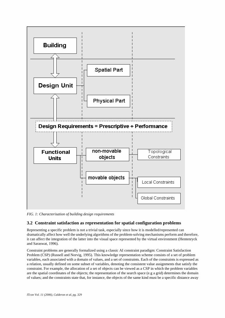
In this investigation, the framework adopted with regards to encapsulation of the design requirements (knowledge) is that those are represented at a functional unit level on movable and non-movable objects which are part of the spatial configuration problem (Fig. 1 illustrates the characterisation framework). According to the SEED model, a functional unit “represents a collection of requirements for a design unit. The requirements consist of constraints and criteria on shape, size, placement, material make-up, etc of this design unit, which may also impose requirements on other design units." (Fleming et al, 1994). Furthermore, functional unit constraints are divided into three categories: topological, local and global constraints. The description, formalisation in CLP(FD) and implementation in the constraint solver of each category is explained in detail in the example section.
Finally, it must be noted that restrictive non-geometric attributes like the lighting levels of a room were not implemented in the SEED project. However, CLP(FD) introduces richer semantic data structures that allow semantic objects, e.g. arithmetic and non-arithmetic expressions, to be directly expressed and manipulated in the so called computational domain, in this case, a Finite Domain (FD). Hence, within each category a further subdivision has been introduced, geometrical (e.g. minimum and/or maximum distance to paths, walls, etc) and engineering (e.g. luminosity, temperature, etc, essentially non-geometrical). This distinction between geometrical and engineering can also be found in the work carried out by Fernando et al. (Fernando et al, 1999), (Fa et al, 1993) and the example section illustrates its application.
ITcon Vol. 11 (2006), Calderon et al, pg. 329
FIG. 1: Characterisation of building design requirements
3.2 Constraint satisfaction as representation for spatial configuration problems Representing a specific problem is not a trivial task, especially since how it is modelled/represented can dramatically affect how well the underlying algorithms of the problem-solving mechanisms perform and therefore, it can affect the integration of the latter into the visual space represented by the virtual environment (Hentenryck and Saraswat, 1996).
Constraint problems are generally formalized using a classic AI constraint paradigm: Constraint Satisfaction Problem (CSP) (Russell and Norvig, 1995). This knowledge representation scheme consists of a set of problem variables, each associated with a domain of values, and a set of constraints. Each of the constraints is expressed as a relation, usually defined on some subset of variables, denoting the consistent value assignments that satisfy the constraint. For example, the allocation of a set of objects can be viewed as a CSP in which the problem variables are the spatial coordinates of the objects; the representation of the search space (e.g a grid) determines the domain of values; and the constraints state that, for instance, the objects of the same kind must be a specific distance away

ITcon Vol. 11 (2006), Calderon et al, pg. 330
from each other (see Fig. 2). Thus, a CSP problem is a combinatorial problem (the resolution of a configuration problem is also a combinatorial problem) which can be solved by search. There are two reasons for choosing to represent and solve a problem as a CSP. First, the representation as a CSP is often much closer to our original problem: the variables of the CSP directly correspond to problem entities, and the constraints can be easily expressed. This makes the formulation simpler and the solution easier to understand. Second, CSP algorithms are very fast which is important to maintain the user-centred aspects of VR.
FIG. 2: Constraint satisfaction problem (CSP) is a knowledge representation scheme which consist of a set of problem variables, each associated with a domain of values, and a set of constraints.
3.3 Constraint programming as a framework Constraint programming provides a powerful conceptual and practical framework to programming, modelling and problem solving. This framework has proven to be successful in many relevant application areas such as scheduling, resource allocation, configuration and design and as stated by Hentenryck himself (Hentenryck and Saraswat, 1996): “constraint programming has the potential for interesting related domain applications in 3D graphics and virtual reality”. The basic idea is that many interactions amongst objects (e.g., attachments, minimal distances, noncollision, etc) or general integrity rules (such as energy conservation laws) can be considered as constraints and implemented as such. Basically, constraints can be used to enforce hidden relations between objects and thus make sure that the simulated virtual world does not depart much from the real one.
The essence of constraint systems based on a constraint programming framework is that these systems take advantage of the properties which constraints naturally enjoy and which are vital to support total interactive VR systems. Firstly, constraints restrict the possible values that variables can take and thus, representing partial information about the variables of interest. For instance, an object's spatial variables can be locally constrained. That is, the allocation (spatial variables) of an ATM (Automatic Teller Machine) object can be restricted by the distance to, for instance, a wall and/or to an area, e.g the queuing area (see Fig. 3). Therefore, when the user visually interacts in the virtual environment with the object ATM, the spatial variables are partially constrained to a specific distance to the wall. Consequently, this property helps to match the design requirement (e.g ATM must be close to a wall) to visual space represented by the virtual environment and to the underlying problem-solving mechanisms (e.g constraint propagation) implemented in the constraint system.

ITcon Vol. 11 (2006), Calderon et al, pg. 331
FIG. 3: An object's spatial variables can be locally constrained. For instance, the allocation (spatial variables) of an ATM (Automatic Teller Machine) object can be restricted by the distance to, e.g. a wall and/or to an area, e.g. the queuing area.
Secondly, constraints are additive/incremental: in other words, given a constraint c1, let us say, X+Y > Z, another constraint c2, can be added, say, Y <Z. The order of imposition of constraints does not matter; all that matters at the end is that the conjunction of constraints is in effect. For example, constraint programming supports the addition by the user of new constraints on the configuration of objects. The user could select the objects in the virtual environment and state, for instance, the distance amongst them. Consequently, this additional constraint will be added, on-the-fly, to the original configuration problem. Thirdly, constraints are none-directional: typically a constraint on, for example, the three Euclidian variables (X,Y,Z) of an object can be used to infer a constraint on X given constraints on Y and Z, or a constraint on Y given constraints on X and Z, and so on. Finally, constraints are declarative and, particularly well suited for spatial relationships between objects. This means that a relationship is expressed, for example, an ATM machine/object must be an specific distance away from the queuing area in a bank hall (see Fig. 3), without specifying a computational procedure to enforce that relationship.
As previously remarked, all these properties support the basis for the implementation of fully interactive systems because they support the implementation of transparent and interactive mechanisms between the design requirements (knowledge), the visual space and the implemented problem-solving mechanisms. Table 2 summarises the constraints properties.
TABLE 2: constraint properties
Constraint properties
Constraints represent partial information about the variables of interest
Constraints are additive/incremental
Constraints are declarative are well suited to express spatial relationships amongst objects
3.4 Constraint Logic Programming over Finite Domains Constraint Logic Programming (CLP), as it is known from Artificial Intelligence, is the most appropriate formalism to interactively handle a constraint satisfaction problem in a virtual environment. The argumentation is threefold: CLP is a declarative formalism; it supports interactivity and, finally, specific programming environments have been developed.
CLP systems support a declarative programming style: the user specifies the problem as a goal and the system searches for solutions. That is, the user states what has to be satisfied but not how. The whole problem is about spatial configuration tasks related to building design. These are formally equivalent in its non-interactive form to the "n-queens" problem, a classical AI problem, as it consists in searching a space to minimise the number of conflicts. It is of course a well-described problem (Russell and Norvig, 1995) (Korf, 1996), on which very different methods can be applied, including branch-and-bound search, constraint programming and heuristic repair. The choice between approaches was made based not so much on their algorithmic properties as on their expressivity, defined as their knowledge representation capabilities. To illustrate the problem of expressivity, simpler examples such as the "allocation of vending machines" in a bank were solved by both methods: a user had to allocate a

ITcon Vol. 11 (2006), Calderon et al, pg. 332
configuration of four vending machines in a bank hall according to the constraints imposed in the configuration (Calderon and Cavazza, 2001). As previously stated, this example is formally equivalent, in this case, to the``4-queens" problem. Within search, an instance of the conflict criterion is Y1-Y=/=(X1-X), Y1-Y=/=(X-X1) which, states that two vending machines cannot be in the same diagonal (using a rectangular grid as a search space). Within CLP, the constraint had a more natural declarative definition, for example, (X-Xm)+(Y-Ym)<Dmax, which states that a vending machine must be a Dmax away from a non-movable object (Xm, Ym) On trivial examples like this one, search and constraint solving are equivalent. However, as the application gets more realistic and complex, expressivity of the constraint formalism, that is the ease of expressing a variety of operations in a simple, declarative and powerful way, is increasingly more important.
CLP(FD) systems use the constraints actively, pruning the search tree in an "a priori" way rather than using constraints as passive tests leading to a "generate and test" or "standard backtracking" behaviour. These new inference mechanisms in the finite domain part of a CLP(FD) system were pioneered by CHIP (Dincbas et al, 1988). The key aspect is the tight integration between a deterministic process, constraint evaluation, and a nondeterministic process, search. It is the active view of constraints which is exploited in CLP implementations to overcome the well-known performance problems of "generate and test" (Fruhwirth et al, 1992). CLP(FD) systems exhibit a data-driven computation and can be characterised as "constraint and generate". These solving mechanisms provide a strong basis for its integration in an interactive VR system.
Consequently, the factors which make a CLP(FD) language suitable for the implementation of an interactive constraint solver are: the expressiveness awarded by the high level of these languages, the combination of search and incremental constraint solving capabilities (i.e when adding a new constraint to an already solved set of constraints, the constraint solver does not start from scratch), the short development time while exhibiting efficiency comparable to imperative languages and the fact that CLP(FD) is fast enough to react in “real-time” to the user’s input configuration (Hermenegildo, Online) as we will demonstrate in the application example.
4. AN INTELLIGENT CONFIGURATION SYSTEM An intelligent configuration system is used as an application example. The data used in this configuration scenario is derived from a simple yet realistic example which uses real-world design knowledge in terms of building interior design for offices (a bank agency in our case). More specifically, the data used for both objects and constraints was drawn from real specifications (European Commission, 2000) (British Educational Communications and Technology agency, 2001).
In our intelligent configuration system, the spatial relationships between the objects in a layout configuration are all known, formulised in CLP and implemented in GNU Prolog. Moreover, the objects involved in the configuration have been divided into non-movable objects (e.g. ventilation ducts, sources of heat, etc) and movable objects (e.g furniture: sofas, desks, etc). In our case, this means that whilst all objects are used when formalising the design requirements, the user will only interact with the movable objects: the furniture. Consequently, when the user decides to reallocate a movable object (e.g. a sofa), this, in turn, disrupts the imposed constraints in the whole configuration and forces the system to re-allocate the remaining movable objects to generate a solution compatible with all the design requirements. The decision to make some objects movable or not is arbitrary (and it can be easily reversed) but it is made on the basis of the relevance for the application (in this case interior building design). Hence, it makes sense to have a movable desk and not a ventilation duct which is part of the mechanical and electrical (M&E) equipment.
In our case, the movable objects are: one vending machine, two desks (which represent the customer attention area), two sofas (waiting attention area), two automatic teller machines (ATMs), three fire extinguishers and four bins. This constitutes a subset of 14 objects: considering the size of the environment and that the overall size of the available set of constraints for each object is eleven, the corresponding search space (abstract problem space) is substantial and indeed impossible to search systematically, even less so in real-time.
4.1 System overview and architecture The system is an interactive 3D environment in which the user can freely navigate and interact with the world objects (e.g. by dragging and dropping them). That is, the system initially proposes a first solution (in the form of a configuration of objects) which serves as a starting point for user’s exploration of possible configurations. Once the user has explored this configuration, he can interact with it by displacing the constituent objects. The correct

ITcon Vol. 11 (2006), Calderon et al, pg. 333
allocation of an object instantly triggers new solutions (configurations) from the solver which, in turn, are displayed in the virtual environment.
The system has been developed using the Unreal TournamentTM (UT) game engine as a development environment. In addition to being an efficient graphics engine, it includes a development environment in which object behaviours and interactions with objects can be programmed, even for immersive systems (Jacobson and Hwang, 2002)(Lewis and Jacobson, 2002). The UT environment also supports the overall software architecture by allowing integration of external modules via dynamic link libraries or windows sockets. We have used TCP sockets as a communication mechanism between the visualisation engine and the intelligent configuration system (see Fig. 4).
FIG. 4: System Architecture: a GNU Prolog solver is integrated in the Unreal EngineTM
The intelligent configuration module is based on Constraint Logic Programming (CLP) has been developed using CLP(FD) as a software technology. More specifically, the CLP(FD) framework provides all the tools to represent design knowledge, mapping design constraints to “formal” constraints in CLP which express e.g. distance between objects, compatibility between materials, etc. In addition, it enables incremental solutions to be computed in user real-time, which ensures the interactivity of the system as a whole. We have used GNU Prolog (Diaz and Codognet, 2001) as a programming environment, which contains an efficient constraint solver over Finite Domains (FD). This allows the implementation of many different types of constraints which can be represented over a finite domain, i.e. an ordered list of properties. This makes it possible to represent “semantic” constraints, i.e. constraints involving object properties such as (materials, friction coefficient, resistance to fire, etc). In the next section, we give a more detailed insight into the implementation considering the specific techniques used.
It must be noted that, according to our results, the communication time for the overall cycle is on average less than 15ms, which is fully compatible with the user interaction (as the user is not navigating when interacting with objects).
4.2 Formalisation of design knowledge in CLP Following the characterisation of building requirements expressed in the conceptual framework, in this case the design unit is the spatial configuration of the furniture suite of a bank agency. For our purpose, the encapsulation of design requirements was adopted at functional unit level: movable and non-movable objects (see Fig. 5). The constraints or design requirements on those objects (functional units) have been classified in three groups: topological, local and global constraints. These constraints incorporate geometric as well as more “semantic” attributes such as lighting and temperature. Consequently, to assess a proposed design unit (e.g the furniture layout of a room), the designers select and input the attribute values on the functional units (objects) and their “performance” is interactively evaluated by the user through the virtual environment.

ITcon Vol. 11 (2006), Calderon et al, pg. 334
FIG. 5: CLP formalisms enable the transformation of design knowledge into a set of constraints
The topological constraints are inherited from the 3D environment and are transformed into Prolog facts which describe room’s topological characteristics. Consequently, from the user’s perspective, there is a perfect matching between the topological characteristics of the 3D environment and the Prolog facts implemented in the solver. For instance, sources of heat or radiators and different lighting levels are visually apparent to the user in the 3D environment. Therefore, both characteristics have been formalised as Prolog facts as follows (also illustrated in Fig. 6): source_of_heat([X0/Y0, X1/Y1/,X2/Y2]); luminosity([lightingvalue = Area0, lightingvalue = Area1, lightingvalue = Area2])
FIG. 6: Topological constraints (i.e. lighting levels) are inherited from the 3D environment and are transformed into Prolog facts which describe room’s topological characteristics. Consequently, from the user’s perspective, there is a perfect matching between the topological characteristics of the 3D environment and the Prolog facts implemented in the solver
These facts define the coordinates of the sources of heat (a list of points X/Y in the search space) and the regions where the lighting level is less than 300 lux (a list whose each element defines a lighting value and an associated rectangle in the search space). In the example, there are also definitions for the location in the 3D environment of the following elements: power points, ventilation ducts, the central fountain, queuing area, counters, walls, luminosity and temperature levels.
Local constraints are constraints on the attributes of a single object and specify how the object relates to the topological characteristics of the virtual environment. This means that when the user disrupts the configuration, he is effectively interacting with the underlying design knowledge expressed through the properties/attributes of the object. For instance, let us imagine that the user wanted to reallocate the desk object. The new object location

ITcon Vol. 11 (2006), Calderon et al, pg. 335
would be constrained by the object’s attributes (or design requirements) expressed in the corresponding Prolog clause (also shown in Fig. 7): object(sofa [furniture(4),heat(4), duct(4), wall(26), queue_area(3), temperature (19..24)]. This clause reads as follows: a desk should be placed at a minimum distance of 4 from any ventilation duct, at a minimum distance of 3 from a queue area and, inside an area whose temperature is between 19 and 24 degrees Celsius. As previously remarked, the overall size of the available set of constraints for each object is eleven. That is, there are nine local constraints available and at least two global constraints: how the object relates to the rest of objects in the configuration and how it relates to the object of the same type (sub-configuration). Table 3 summarises the local constraints (geometrical and engineering) available. Not all the objects have to comply with all the constraints.
FIG. 7: Local constraints are constraints on the attributes of a single object and specify how the object relates to the topological characteristics of the virtual environment
TABLE 3: Local constraints available to each object. Not all objects have to comply with all the constraints
Geometrical Constraints Engineering Constraints
A minimum distance away (different for each object) from
sources of heat.
ventilation-ducts
power-point
Luminosity: an object has to be in an area with luminosity levels between for instance, 300-500 flux.
minimum and max distance (different for each object) of each segment of a path. Each point "around" the path (or the distance) is not a solution.
Temperature: an object has to be in an area with temperature levels between for instance, 19-24 degrees.
A predefined offset area and the area of each furniture are not in a feasible solution
A fixed and / or minimum and / or maximum distance to each wall
Global constraints are particularly relevant to express design requirements which involve group of objects. Each object has at least two global constraints imposed: one which relates that object to the rest of objects in the configuration and another which relates the object to its own sub-configuration (except when the sub-configuration consists of just one object). For instance, let us consider the object “desk”. This object relates to others in the following way: the constraint distance_constraint(desk, desk, 6, 12) ensures that a minimum and a maximum distance is kept between desks; distance_constraint(desk, sofa, 6,20) forces any desk object to be within a certain distance (6 to 20) of any sofa; distance_constraint(desk, bin, 5,12) is similar to the one just described; and, finally, the constraint distance_constraint_others(8,1000) sets a minimum distance between the object desk and any other object (see Fig. 8).
At implementation level, it must be noted that there are two implementation levels for either local or global

ITcon Vol. 11 (2006), Calderon et al, pg. 336
constraints: descriptive and primitive. In the descriptive level the user of the system (e.g the designer) states the constraint, or what it needs to be solved, without being concerned about how it is resolved. Hence, constraints can be easily asserted or retracted from the constraint solver. On the other hand, the primitive level is concerned with the optimization of the resolution process. That is, at a primitive level the main concerned is to find, or define, the most appropriate finite domains predicates which assure an efficient/fast solver.
FIG. 8: Global constraints are particularly relevant to express design requirements which involve group of objects
Fig. 9 shows an example of this. In this case, the descriptive level is concerned, firstly with matching the lighting levels defined in the solver, using the topological constraint lumninosity [LAreas], to those on the 3D environment; and secondly with defining the acceptable levels for a particular object, in this case a desk. At a primitive level the constraint set_imposs_rect(LRect, 0, X, Y) ensures that an object X/Y, in this case the desk, cannot belong to a given rectangle A1/B1-A2/B2, defined by the 2 diagonal coordinates, in which the lighting levels are inferior to imposed minimum threshold or acceptable level. Thus, this further level of description maintains, at a descriptive level, the declarative nature of CLP as well as assuring an efficient solver.
FIG. 9: Constraints implemented at descriptive and primitive level
4.3 Interactive exploration of solutions First running the system results in the solver producing a set of variable allocations satisfying all the design constraints. These variables are translated in the virtual environment in terms of object types and positions, which instantiates all furniture objects at their respective locations, thus constituting a first design solution (object

ITcon Vol. 11 (2006), Calderon et al, pg. 337
configuration). Once the initial configuration has been deployed, the user can explore this first solution by navigating in the virtual environment and test variants of the configuration by changing objects’ positions. For instance, let us imagine that the user wants to refine and/or further explore the configuration: e.g an ATM is too close to the queuing area. Consequently, the user seizes the ATM object and proceeds to reallocate it while he explores the 3D environment. Once a suitable location has been found the user will drop the object triggering the corresponding Unreal events. In other words, when the object is dropped an unreal event is triggered which sends the object’s location to the solver in the appropriate query format (e.g atm=1/12.). When the user drops the atm object he is, therefore, disturbing both the local and the global constraints attached to it. As shown in Fig. 10, an ATM object, can only be allocated away from a, e.g, source of heat (heat(Dist)) and, similarly, it needs to be away from any other object of the configuration as specified in: (distance_constraint(Obj1, Obj2, DMin, DMax) where Obj1 is, in this case, the ATM and Obj2 any other object. Thus, when the user decides to reallocate the object by dragging and dropping it to a new position, this, in turn, disrupts the imposed constraints in the configuration and forces the system to “propagate” all the constraints and to generate a solution compatible with the design requirements (see Fig. 11). This propagation and a non-deterministic search are the basic mechanisms for interactive exploration of solutions.
FIG. 10: The solver uses generic constraints that can be instantiated on the VE’s objects
This example shows how the user utilises the “natural” interaction mechanisms of VR to interact with the configuration problem and how the automatic reconfiguration of the configuration problem (see Fig. 11) enables him to visualise the consequences of his interactions on the configuration

ITcon Vol. 11 (2006), Calderon et al, pg. 338
FIG. 11: The user refines a given configuration by reallocating an object. As a result of this, the environment reconfigures itself
5. DISCUSSION As it has been mentioned at the beginning of this paper, reactive planning faces a number of difficult technical challenges. In this section we discuss how our results address those problems.
5.1 Response Time As it has been pointed out in previous sections, to implement reactivity at real-time, that is at the next tick, one key aspect from the user-centred perspective is that current AI techniques are often much less interactive that would be required for a complete integration into virtual environments. We have opted for CLP over FD as software technology because it is fast enough to react in “real-time” to user’s input configuration. In particular, GNU Prolog is a Prolog compiler (Logic programming) with constraint solving capabilities over finite domains. That is, GNU Prolog discretizes the infinite domain into a finite number of components and, then, applies constraint satisfaction techniques (arc-consistency).
From a practical implementation standpoint, there are two ways of making our application as fast as possible when using GNU Prolog as programming environment. These two different ways stem from the fact that GNU Prolog combines the power of constraint programming with the declarativity of logic programming. In theory one of the main advantages of declarative languages is that they encourage the programmer to consider the declarative meaning independently of their procedural meaning. In practice this is not entirely correct and one of the ways of improving the efficiency of the programs is by changing the order of clauses, goals and constraints. This is, of course, a trial and error process. The other way of improving efficiency is by using different propagation techniques to the constraints on FD. GNU Prolog offers two different propagation techniques (solving mechanisms) to solve arithmetic constraints: full arc-consistency and partial arc-consistency. The latter leads to less propagation than the former but are generally more efficient.
In our example application we have experimented with reordering the clauses and constraints and with different grid size for the search space. The finest possible mesh (512 x 512) which could be implemented with GNU Prolog v.1.2.8-1 would have a cell size of 37mm by 37 mm in real units, That is, in the real world. The following results (see table 4) were obtained when using partial arc-consistency to solve the geometric and engineering constraints.

ITcon Vol. 11 (2006), Calderon et al, pg. 339
TABLE 4. The results show the total time that the solver has taken to calculate ALL the possible solutions
Grid Size (number of cell in the mesh)
Constraints order changed 360 x 360 512 x 512
No 10 ms 70ms
Yes 5 ms 60ms
Our choice of CLP(FD) as software technology has been made based on a series of factors, declarative nature of the formalism being one of them.
5.2 Formalism Knowledge Representation In previous sections, we have also explained that in order to successfully use CLP(FD), we must first transform our building design constraints into CSP which, in turn, are easily expressed in CLP(FD).
There are two reasons for choosing to represent and solve a problem as a CSP. First, the representation as a CSP is often much closer to our original problem the variables of the CSP directly correspond to problem entities, and the constraints can be easily expressed. This makes the formulation simpler and the solution easier to understand.
However, CLP over a Finite Domain (FD) as representation formalism has some limitations. FD constraints are constraints on integer valued variables rather than real valued variables. Real interval constraints are better suited to deal with trigonometric and non-linear arithmetic constraints. In GNU Prolog, FD expressions are not restricted to be linear. However, non-linear arithmetic constraints, for instance R3=R1*R2-I1*I2, usually yield less constraint propagation than linear constraints. That is, when a non linear constraint is encountered during computation, then it is delayed until it becomes linear.
5.3 Interactive cycle The interaction cycle is determined by the speed at which new solutions are computed. In other words, the sampling rate of object manipulation in the virtual environment must be compatible with the result production granularity of the problem solving algorithm. Regarding the visualisation element, Unreal provides us with mechanisms to play with the tradeoff between the bandwidth and the amount of data we want to ship to all the clients. This is because certain operations, like spawning actors (objects) as a result of a user’s interaction with the system, are very “expensive” or in other words could slow down the “game play” if they are not designed efficiently. This means, that a real-time reactive environment will depend not only on using the adequate technology to implement the constraint solver but also on the overall system architecture, especially on how the reality is shared between the server and the client(s). Unfortunately, at this point in time, we do not have enough data to explain this matter further.
6. CONCLUSIONS We have presented a novel framework for the use of virtual environments in interactive virtual design. For design applications, this framework supports the expression of design knowledge in the VE and the exploration of new design solutions by refining previous ones, which would appear a natural process to many users. In other words, this framework supports the interactive exploration of the solution space of a spatial configuration problem.
The system has a potential for extension in different directions. For instance, in terms of mechanisms of user interaction, we envisage offering yet more interactivity to the user for more efficient object manipulation. For instance, it is fairly simple to “constrain” some objects in the virtual environment what it would ensure that an object will remain at the some location after the user has interacted with the configuration. As well, taking advantage of the incremental capabilities of the solver, we could give the user the possibility of adding objects on-the-fly and to choose the constraints for that objects from a set of predefined constraints.
In its current form, the system is still faced with a number of limitations, the most important being the absence of an explanatory module that would provide the user for justifications for the proposed solutions. Such a module is even more important to explain why there exist no acceptable solutions for some object positions proposed by the user. Further work will be dedicated to providing more feedback from the configuration system.
ITcon Vol. 11 (2006), Calderon et al, pg. 340
7. REFERENCES Axling, T., Haridi, S, and Fahlen, L. (1996). Virtual reality programming in Oz. In Proceedings of the 3rd
EUROGRAPHICS Workshop on Virtual Environments, Monte Carlo.
Aylett, R. and Cavazza, M. (2001). Intelligent Virtual Environments - A State-of-the-art Report. Eurographics.
Bryson,S., Earhshaw, R.A. and Vince, J.A. (1995). Virtual Reality Applications, chapter 1: approaches to the successful design and implementation of VR applications, pp 3-15. Academic press, 24-28 Oval Road, London, NW1 7DX, 1st edition.
British Educational Communications and Technology agency. (2001). Technical report on Health and Safety: planning the safe installation of ICT in schools.
Burdea, G. and Coiffet, P. (1994). Virtual Reality Technology. ISBN: 0471086320. Wiley-Interscience, 1st Edition.
Calderon,C., Cavazza., M. (2001). Intelligent Virtual Environments to interactively Solve Spatial Configuration Tasks. VSMM 2001, The 7th International Conference on Virtual Systems and Multimedia, Berkeley, California, USA, October 25 - 27, 2001. http://www.vsmm.org/vsmm2001/
Codognet, P. (1999). Animating Autonomous Agents in Shared Virtual Worlds, proceedings DMS'99, IEEE International Conference on Distributed Multimedia Systems, Aizu, Japan, IEEE Press.
Diaz, D. and Codognet, P. (2001). Design and Implementation of the GNU Prolog System. Journal of Functional and Logic Programming, Vol. 2001, No. 6.
Dincbas, P., Van Henteryck, M., and Simonis, H. (1988). The constraint logic programming language chip. In the proceedings of the international conference on fifth generation computer systems FGCS-88.
European Commission – Joule Thermie Programme- (2000). Technical report: tax office extension: Enschede (The Netherlands).
Fa, M., Fernando, T., and Dew, P.M. (1993). Interactive Constraint-based Solid Modelling using Allowable Motion, ACM/SIGGRAPH Symposium on Solid Modelling and Applications, pp 243-252.
Fernando, T., Murray, K., Wimalaratne, P. (1999). Software Architecture for a Constraint-based Virtual Environment, , ACM International Symposium on Virtual Reality Software and Technology, VRST 99, London. UK.
Fleming, U., Coyne, R., Fenves, S., Garrett, J., Woodbury, R. (1994). SEED –Software Environment to Support the Early Phases in Building Design. Proceedings of IKM94, Weimar, Germany, pp 5-10.
Fruhwirth, A., Herold, T., and Kunchenhoff, V. (1992). Constraint logic programming: an informal introduction. Technical report, European Computer-Industry Research Centre (ECRC), ECRC GMBH, ARABELLASTR. 17 D-8000 Munich 81, Germany.
Hentenryck. P, and Saraswat, V. (1996). Strategic directions in constraint programming. ACM computing surveys, 28(4): 701-726.
Hermenegildo, M (Online) Some challenges for constraint programming. http://www.clip.dia.fi.upm.es/herme/con.html, last visited on 21/07/05, 2005.
Jackson, P. (1999). Introduction to Expert Systems. Addison Wesley.
Jacobson, J and Hwang, Z. (2002). Unreal Tournament for Immersive Interactive Theater. Communications of ACM, Vol. 45, No. I, January 2002. pp 39-42.
Korf, E.R. (1996). Artificial intelligence search algorithms. Technical report, NSF Grant IRI-9119825 and a grant from Rockwell International, University of California, Los Angeles, Ca. 90095.
Kamara, J. (1999). Client requirements processing in construction: a new approach using qfd. Journal of Architectural Engineering, 5(1): 89-97.
Lawson, B. (1997). How designers think: the design process demystified. Architectural Press, Linacre House, Jordan Hill, Oxford OX2 8DP, Third edition.

ITcon Vol. 11 (2006), Calderon et al, pg. 341
Lottaz, C., Clément , D., Faltings, B. and Smith, I. (1999). Constraint-Based Support for Collaboration in Design and Construction, Journal of Computing in Civil Engineering, Vol. 13, No. 1, pp. 23-35.
Lewis, M and Jacobson, J. (2002). Games Engines in Scientific Research. Communications of ACM, Vol. 45, No. I, pp 27-31.
Nomura, Junji, Hikaru Ohata, Kayo Imamura, Robert J. Schultz. (1992). Virtual Space Decision Support System and Its Application to Consumer Showrooms. Matsushita whitepaper.
Rivard, H. (1997). A building design representation of conceptual design and case-based reasoning. PhD thesis, department of civil and environmental engineering, Carnegie Mellon University, Pittsburgh, USA.
Russell, S.J. and Norvig, P. (1995). Artificial Intelligence: a modern approach. Prentice-hall, Inc., Upper Saddle River, New-Jersey.