cltr-20150656.04c-rev stormwater design council response
TRANSCRIPT

SUTHERLAND OFFICE LOCATIONS: SYDNEY-CBD SUTHERLAND WOLLONGONG NOWRA GOULBURN PICTON SINGLETON ABN 51 003 316 032 Suite 45, 40-44 Belmont Street, SUTHERLAND NSW 2232 PO Box 477, SUTHERLAND NSW 1499
Tel: 02 9521 3088 Fax: 02 9521 3066 Email: [email protected] www.jonesnicholson.com.au
Page 1 of X
10 May 2018 Our Ref: CLTR-20150656.04C The Gallery at Engadine Pty Ltd Suite 1, Level 9, Strathfield Plaza 11 The Boulevarde Strathfield NSW 2135 ATTENTION: MR CRAIG BENNETT Dear Craig, DEVELOPMENT DESCRIPTION: NEW RESIDENTIAL DEVELOPMENT – “THE GALLERY” CLIENT: THE GALLERY AT ENGADINE PTY LTD LOCATION: 1081-1089 OLD PRINCES HIGHWAY
ENGADINE NSW 2233
Jones Nicholson has been engaged by The Gallery at Engadine Pty Ltd to assess the impact the that the proposed residential development at the above-mentioned site, will have on the existing Council stormwater trunk drainage network. In completing the stormwater assessment of the existing supporting infrastructure and the design of the development stormwater infrastructure, Jones Nicholson reviewed and designed in accordance with relevant Australian Standards and Council policy. To ensure the design is in accordance with Council stormwater requirements, Jones Nicholson has assessed and provided responses to queries raised by Council about the design. We will address all items individually. 1. The latest stormwater plans (C120-6 and C121-5) as shown in the transmittal have not been issued to Council for assessment. Please refer to latest design drawings in Appendix A. 2. Council’s Comments are based on following plans & stormwater report by Jones & Nicholson a. Ground Stormwater Plan C120-5 b. Stormwater Drainage Longitudinal Section C121-4 c. OSD Tank Plan C125-2 Please refer to latest design drawings in Appendix A. 3.Information related to catchment area, flow rates, pervious areas & orifice size shown in the Stormwater Report dated 25 Jan 2018 & plans submitted by Jones Nicholson and DRAINS model is not consistent. Please refer to the latest plans and updated DRAINS model provided for coordinated figures.

10 May 2018 Our Ref: CLTR-20150656.04C
Page 2 of 6
4.The DRAINS model does not include 10, 25, 30 & 45 min duration storms and shall be updated. The 25-minute storm event was viewed as the worst storm duration and has been adopted within calculations and the models. We have included the additional storm events in updated DRAINS model for your information though. 5.There are inconsistencies with respect to impervious and pervious areas as well as time of concentration for the sub-catchment areas in the DRAINS model. It appears that most of the landscaped areas considered in the model are above the basement car park and paved. The DRAINS model has been updated following the amendments to the landscaping drawings. We have broken the areas down into 3 catchments. These areas are:
Catchment for Building A – Total: 2,072 m2, Landscaping/ impervious: 81 m2 (4%) Catchment for Building B – Total: 1,715 m2, Landscaping/ impervious: 341 m2 (20%) Catchment for Building C – Total: 1,501 m2, Landscaping/ impervious: 451 m2 (30%) Total site area = 5,288 m2.
6. Proposed connection to the existing drainage system in Old Princes Highway requires further investigation into condition and performance of the system, which include supporting calculations to demonstrate the capacity of the system (20%, 5% and 1% AEP storm events). A CCTV inspection of the existing stormwater drain in the Old Princes Highway shall be carried out to assess its condition and potential remedial/upgrade. The inspection shall be carried out from the nearest stormwater pit on the upstream of the site boundary to the existing pit downstream of the site. Council has agreed with Bouvardia Constructions and HYZ Developments on the 23rd April 2018 as per email from HYZ Group dated 8th May 2018 ay 7.07am that the existing 375mm pipe in the Old Princes Highway does not require upsizing. Council also advised that any maintenance of this pipe is Councils responsibility. 7. The discharge from the OSD tank to existing drainage system in the car park in Miyal Place does not meet Council requirements. The criteria for the subject site is to limit post development discharge during 1 in 100-year storm event back to a pre-developed (greenfield state) discharge in 10 year ARI storm event. If the PSD for the site exceeds this amount, it will be a requirement to upsize the OSD system. The DRAINS model and OSD design has been amended so that the post development 100 years ARI storm event runoff, is restricted via the OSD network to control discharge for to the pre development 20 year ARI event runoff. This method was discussed and approved during the meeting held between the Builder, Council and Jones Nicholson on 23/4/18. It was calculated that the 20 year ARI runoff will be 199L/s. This has led to the OSD tank size to increase to a total of 76 cubic metres storage. The orifice size was also required to be increased to 298mm in diameter. Documentation has been adjusted to suit these amendments. 8. The stormwater outlet pipe (375mm RCP) and Orifice size (305mm) from OSD tank are larger than the existing pipe downstream and is not acceptable. See Appendix A for latest drawings. The orifice size is 298mm in diameter. Investigation also identified that we are connecting into a 375mm RCP downstream. Therefore, it will not be larger than existing.

10 May 2018 Our Ref: CLTR-20150656.04C
Page 3 of 6
9.Proposed connection to the existing drainage system in the Miyal Place car park area requires further investigation into condition and performance of the system, which include supporting calculations to demonstrate the capacity of the system (20%, 5% and 1% AEP storm events). A CCTV inspection of the drainage line shall be carried out to assess its condition. The inspection shall be undertaken from the existing stormwater pit in the Council’s car park area to Stormwater pit in Miyal Place. The proposed connection point in Miyal Place is labelled EX A01 on Jones Nicholson drawing C120 rev 7. Council advised Bouvardia and HYZ Developments on the 23rd April 2018 as per email from HYZ Group dated 8th May 2018, that the proposed connection point, which is a kerb inlet pit and councils 375mm pipe running downstream from this pit does not require upsizing. This is as a result of Bouvardia Constructions revising the OSD system to restrict the flow from the development to the 20 year ARI runoff of 199L/s. Council also confirmed that any maintenance of this kerb inlet pit and 375mm pipe is Councils responsibility. 10. The DRAINS model shows that in 1% AEP event, the overland flow from the site to the Miyal place car park will exceed 150l/s (110+14+20+10) and is not acceptable. There is a misunderstanding in reviewing our model based on the above. The 110L/s overflow is contained within the OSD tank. Within the model, the overflow height is set to the control chamber weir level within the OSD tank. Therefore, this flow will not upwell out of the tank and will instead fall to the tank outlet. The outlet pipe has been sized for the flow from the orifice (20% AEP event) in addition to the weir flow from the 1% AEP event. We have amended our model with the revised landscaping areas. This has reduced the amount of runoff. This leaves 52L/s of runoff from overland flow in the 1% AEP event. For a site this large, this is a very small flow which is the equivalent of one residential kerb discharge drain. Overland from the three building catchment areas are 20L/s, 14L/s and 9L/s respectively. An additional 9L/s is expected from the area around the OSD. 11. Outlets in the DRAINS model are assumed as freely discharging to the atmosphere. The consultant shall demonstrate that the OSD tank will not have a “Drowned Outlet” or downstream controlled. The tailwater influences will affect the discharge rate, which is undesirable. Therefore, Hydraulic Grade Line (HGL) assessment of the proposed drainage system shall be undertaken from the existing kerb inlet pit to determine that the Drowned Outlet does not occur at the OSD tank. This has been updated within the resubmitted DRAINS model to show compliance. There will be no drowned outlet to the OSD. The DRAINS model has also integrated runoff from the existing carpark into the kerb inlet pit that we are connecting into. The Hydraulic Grade Line of the stormwater line connecting to the existing pit can be viewed within the DRAINS model. 12. Supporting calculation for the basement pump out pit shall be provided to Council for assessment. This was provided on the DA and other lodged stormwater drawings C120 in the stormwater calculation details. Below are the details.

10 May 2018 Our Ref: CLTR-20150656.04C
Page 4 of 6
Should you need any additional information from us, please feel free to contact the undersigned on 02 9521 3088. For and on behalf of Jones Nicholson Pty Ltd
Jackson Bramley BE (Civil), MIEAust Civil/Structural Project Engineer

10 May 2018 Our Ref: CLTR-20150656.04C
Page 5 of 6
APPENDIX A – Current Design Drawings

120.69 m 2
FUTURE TRANSFER OF LAND
NO WINDOWS WITHIN 3m
x;192.52
x;192.55
x;192.47
x;192.53
x;192.42
x;192.47
x;192.51
x;192.48
x;192.16TIMBER SEAT
TIM
BE
R S
EA
T
TIM
BE
R S
EA
T
1540x2070
1540
x207
0
1540x2070
1540
x207
0
1540
x207
0
NO VENTILATION SYSTEMS WITHIN 6mSERVICES
SUBSTATION
MAIL BOX AREA
TOILETS RAMP
LV PIT HV PIT
x;192.49K
PIT
G
W/
ME
TE
RG
/
ME
TE
RE
LEC
CO
M/
NB
NH
W
DE
S.P
.EX
H
ELEC/COM/
NBN
G/
METER
W/
METER
HW
HW
30.37 m 2
DF3
6.97
%7.
14 %
5.00 %
5.00 %
7.14 %
5.00 %
7.09
%7.
14 %
Ram
p up
1:14
Ram
p up
1:14
Ram
p up
1:14
Ram
p up
1:14
Ram
p up
1:4
Ram
p up
1:8
Ram
p up
1:20
RAMP UP 1:20
RA
MP
UP
1:2
0
RA
MP
UP
1:14
5.00 %Ramp up
1:20
RA
MP
UP
1:4
0
PROPOSED EASEMENTEXISTING EASEMENT
20
FH
4
23
6 FH
1
2
FH
21
20
FH
15
FH
FH
LIFT-C1
FS-C1
F. H
. R.
F. H
. R.
F. H
. R.
OUTLINE
OF SLAB
OVER
450 DIA PIPE
7 8 9
10
1112131415161718191 2 3 4 5
1516171819202122
1 2 3 4 5
1
23
78910
13
1415
11 12 13 14
1 2 3 4 5
1617181920
1718
1920
21
12
34
5
5.00 %
7.09
%7.
14 %
6.97
%7.
14 %
5.00 %
4.90 %
DP
DPDP
DP
DP
DP
DP
DP
DP
DP
DP
DP
DP
DP
DP
DP
DP
DP
DP
DP
DP
DP
DP
DP
DP
DP
DP
DP
DP
DP
DP
DP
DP
DP
DP
DP
DP
DP
DP
DP
DP
DP
DP
DP
DP
DP
DP
DP
DP
DP
DP
DP
DP
DP
DP
DP
DP
DPDP
DP
DP
DP
DP
DP
DP
DP
DP
DP
DP
DP
DP DP
DP
DP
DP
DP
DP
DP
DP DP
DP
DP
DP
DP
OU
TLI
NE
OF
PE
RG
OLA
OV
ER
OU
TLI
NE
OF
PE
RG
OLA
OV
ER
OUTLINE OF PERGOLA OVER
OUTLINE OFPERGOLA OVER
STORMWATER EASEMENT
SUB STATION EASEMENT
OU
TLI
NE
OF
PE
RG
OLA
OV
ER
OU
TLI
NE
OF
PE
RG
OLA
OV
ER
OU
TLI
NE
OF
PE
RG
OLA
OV
ER
OU
TLI
NE
OF
PE
RG
OLA
OV
ER
HW
ELE
C/C
OM
/
NB
N
G
G/
ME
TE
R
R
HW
W/
METER
HW
HW
GR
G
ELEC/COM/
NBN
G/
ME
TE
R
W/
ME
TE
R
HW
HW
R
W.M
.
W.M.
W.M
.
W.M.
W.M.
W.M
.
W.M
.
W.M.
W.M.
W.M
.
W.M.
W.M
.
W.M.
W.M.
W.M
.
W.M.
W.M
.
W.M.
W.M.
W.M
.
W.M.
RWO
RWO
RWO
RWO
RWO
RWO
RWO
RWO
RWO
RWO
RWO
RWO
RWO
RWO
RWO
RWO
RWO
RWO
RWO
RWO
RWO
RWO
RWO
RWO
RWO
RWO
RWO
RWO
RWORWORWORWO
RWO
RWO
RWO RWO
RWORWO
RWO
RWO
RWO
RWO
RWO
RWO
RWO
RWO
RWO
RWO
RWO
RWO
RWO
RWO
Ker
b 30
0w x
150
hK
erb
300w
x 1
50h
Ker
b 30
0w x
150
h
hand
rail
hand
rail
hand
rail
hand
rail
handrail
Ker
b 30
0w x
150
hK
erb
300w
x 1
50h
Ker
b 30
0w x
150
h
panel lift door
roller door
RAMP UP 1:40RAMP UP 1:40RAMP UP 1:40RAMP UP 1:40RAMP UP 1:40
A B C D E F G H I J K L M N O P
1
2
3
4
5
6
7
8
9
10
11
12
OSD
1. DECOMMISSION EXISTING STORMWATER LINE ACROSS SITE FOLLOWING INSTALLATION OF DIVERTED LINE REFER TO TELSTRA STORMWATER DIVERSION PLAN.
2. THERE ARE UNDERGROUND SERVICES IN THE VICINITY OF WORKS. IT IS THE CONTRACTORS RESPONSIBILITY TO LOCATE AND LEVEL ALL SERVICES PRIOR TO COMMENCEMENT OF EXCAVATION EARTHWORKS.
3. EXTERNAL PITS TO BE FITTED WITH WATER QUALITY INERTS IN ORDER TO MEET SSC WSUD REQUIREMENTS.
600SQ
600SQ
600SQ
GD1
600SQ 600SQ
600SQ
600SQ
600SQ
600SQ
600SQ
600SQ
. . .EMERGENCY OVERFLOW PATH
EMERGENCY OVERFLOW PATH
REFER TO INGROUND OSD TANK DETAIL. GL 191.30
FROM SUTHERLAND SHIRE COUNCILS STORMWATER POLICY: REDUCE POST-DEVELOPMENT FLOWRATES FOR EVENTS UP TO/ INCLUDING THE 100 YEAR ARI EVENT.
TOTAL SITE AREA = 5,288m2
PRE IMPERVIOUS = 1,522m2 (28.8%)POST IMPERVIOUS (+ ALLOWANCE FOR LANDSCAPING HARDSTAND) = 3,650m2 (69%)
VOLUME STORAGE REQUIRED = 76m3 (DRAINS)* Q 20YR ARI (25MIN EVENT)- PRE = 199L/s* Q 100YR ARI - POST = 199L/s
NOTE: SUTHERLAND SHIRE COUNCIL OSD POLICY (REFER TO DCP SECTION "STORMWATER MANAGEMENT") ALLOWS 33% OF RAINWATER TANK AS OSD DISCOUNT, PROVIDED RE-USE IS CONNECTED TO INTERNAL USES EG TOILETS OR LAUNDRY WASHING.
VOLUME OSD FROM RWT = 5kL X 33% = 1.67kL;OSD TANK = 37.7m3
TOTAL = 39.4m3 OSD STORAGE
SITE DISCHARGE ACHIEVED VIA ORIFICE PLATE ON OSD OUTLET TO EXISTING KERB INLET PIT.ORIFICE = 21.9 X SQRT (PSD/ SQRT (H))H = HEIGHT OF TOP WATER LEVEL FROM CENTRELINE OF ORIFICE (M)H = (INVERT OF 5YR STORAGE) - (OUTLET CENTRELINE LEVEL)H = RL 190.75 - RL 189.175 = 1.575mTHEREFORE, ORIFICE = 298mm DIAM.
SUBSOIL CALCULATIONS
ASSUME SOIL IS SATURATED TO GROUND LEVEL AND INFLOWS CAN BE APPROXIMATED BY SUB-SOIL FLOW NET:Q = 2/3 X K X H (M3/SEC PER M OF SUBSOIL LINE)ASSUMED SUBSOIL INFILTRATION, K = 1.4 X10^-6 (WEATHERED SHALE)H = HEIGHT = 6M DEEP, LENGTH OF SUBSOIL = 386MQ = 2/3 /140,000 X 6 X 386 = 11L/S
THEREFORE SUGGESTED TOTAL PUMP CAPACITY = 1.1 X (7.4 + 11) = 20.2 L/S.
NOTE: CONTRACTOR TO VERIFY FILL MATERIAL INFILTRATION RATES PRIOR TO CONSTRUCTION. SUPERVISING ENGINEER TO VERIFY DESIGN CHANGES IF INFILTRATION RATES DIFFER SIGNIFICANTLY FROM ASSUMED VALUES
PUMPOUT CALCULATIONS
AREA EXPOSED DRIVEWAY = 100m2 APPROX.MIN VOLUME = 50YR, 2HR = 10.5m3SUGGEST ADOPT V = 10.5m3QPEAK 100YR, 5MIN = 7.4 L/s
RAINWATER TANK CALCULATIONS
VOLUME REQUIRED BY BASIX = 5m3VOLUME PROVIDED FOR RWT NEXT TO OSD FOR MIN 5kL TANK.
OSD CALCULATIONSNOTES
EXISTING COUNCIL INLET PIT IN CARPARKGL. 188.02IL. 181.12 (APPROX)
OUTLET AT IL189.05 PROVIDE 260mmØ ORIFFICE PLATE AND TRASH RACK. TOP OF WIER STRUCTURE AT IL190.75. REFER TO OSD TANK DETAIL ON C070
DISCHARGE FROM OSD TO PIT. LIMIT PSD TO 178L/s
O L
D P R
I N
C E
S H
I G
H W
A Y
RO1
RO1RO1
RO1
RO1
RO1
RO1
RO1
RO1 RO1 RO1 RO1
RO1
RO1
RO1RO1RO1
RO1
GD1
<ø2
25 R
CP
@ m
in 1
.0%
ø225 uPVC @ min 1.0% >
ø225
uPV
C @
min
1.0
% >
ø100STW
ø100STW
ø100STW
ø100STW
ø100STW
ø100STW
ø100STW
ø100STW
ø100STW
ø100STW
ø100STW
ø100STW
ø100STW
ø100STW
ø100STW
ø100STW
ø100STW
ø100STW
ø100STW
ø100STW
ø100STW
ø100STW
ø100STW
ø100STW
ø100STW
ø100STW
ø100STW
STW ø225 @ 1.0% <
STW
ø22
5 @
1.0%
<
STW ø100 @ 1.0% <STW ø225 @ 1.0% <
STW ø225 @ 1.5% <
STW ø225 @
1.5% <
STW ø300 @ 1.0% >
STW
ø22
5 @
1.5
% >
STW
ø22
5 @
1.5
% >
STW
ø22
5 @
1.0
% >
STW ø150 @ 1.0% <
STW ø150 @ 1.0% <
STW ø100 @ 1.0% <
STW ø100 @ 1.0% <
STW ø100 @ 1.0% <
STW ø100 @ 1.0% <
STW ø100 @ 1.0% <
STW ø100 @ 1.0% <
STW ø100 @ 1.0% <STW ø100 @ 1.0% <
STW ø100 @ 1.0%
<
STW ø100 @ 1.0% <
STW ø100 @ 1.0% <
STW ø100 @
1.0% <
STW ø100 @ 1.0% <
STW ø100 @ 1.0% <
STW ø100 @ 1.0% <
STW
ø10
0 @
1.0
% <
STW
ø100
@ 1.
0% <
STW
ø100
@ 1.
0% >
STW ø1
00 @
1.0% <
STW ø1
00 @
1.0% <
STW ø1
00 @
1.0% <
STW ø100 @ 1.0% >
STW ø100 @ 1.0% <
STW ø100 @ 1.0% <
STW ø100 @ 1.0% <
STW ø100 @ 1.0%
<
STW ø1
00 @
1.0%
<
STW
ø100
@ 1.
0% >
STW ø100 @ 1.0%
<
ø100STW
ø100STW
ø100STW
ø100STW
ø100STW
ø100STW
ø100STW
ø100STW
ø100STW
STW ø1
00 @
1.0%
<
STW
ø100
@ 1.
0% <
STW ø100 @ 1.0% < STW ø100 @ 1.0% <
STW
ø10
0 @
1.0
% >
STW ø100 @ 1.0% <
STW
ø10
0 @
1.0%
>
ø100STW
ø100STW
ø100STW
ø100STW
ø100STW
ø100STW
ø100STW
ø100STW
ø100STW
ø100STW
ø100STW
ø100STW
ø100STW
ø100STW
ø100STW
ø100STW
ø100STW
ø100STW
ø100STW
ø100STW
ø100STW
ø100STW
STW ø100 @ 1.0% <
STW ø100 @ 1.0%
<
STW ø1
00 @
1.0% <
STW ø1
00 @
1.0%
<
STW ø1
00 @
1.0% <
STW ø100 @ 1.0%
<
STW ø100 @ 1.0% <
ø100STW
STW ø100 @ 1.0% <
STW ø100 @ 1.0% <
STW ø1
00 @
1.0% <
STW ø1
00 @
1.0% <
STW ø1
00 @
1.0% <
STW ø100 @ 1.0%
<
STW ø100 @ 1.0% < STW ø100 @ 1.0% <
STW ø100 @ 1.0% <
STW ø1
00 @
1.0% <
STW ø1
00 @
1.0% <
STW ø1
00 @
1.0%
>
STW ø100 @ 1.0% >ø100STW
STW ø100 @ 1.0%
<
ø100STW
ø100STW
-
900mm WIDE INTERLOTMENT EASEMENT FOR RELOCATED STORMWATER LINE, LOCATED WITHIN BOUNDARY
-
2000mm ELECTRICAL CABLE EASEMENT
ø225 RCP @ min 1.0% >BOUNDARY
BOUNDARY
BOUN
DARY
CHAMBER SUBSTATION EASEMENT
BOUN
DARY
STORMWATER LINE A REFER TO DRAWING C121 FOR LOGITUDINAL SECTION.
EX A01
B01
B02
B03 B04
B05
STORMWATER LINE B REFER TO DRAWING C121 FOR LOGITUDINAL SECTION.
PROPOSED KERB INLET PIT TO CONNECT INTO EXISTING STORMWATER DRAINAGE LINE.
EXISTING KERB INLET PIT GL. 190.50IL. 189.31
EXIS
TING
STO
RMW
ATER
PIP
EEX
ISTI
NG S
TORM
WAT
ER P
IPE
ø375 RCP @ MIN. 2.5%
<
EXISTING STORMWATER DRAINAGE PIT AND PIPE
1645O
ø100STW
600SQ
STW ø225 @ 1.0% <
900x900
5kL RAIN WATER TANK
STW
ø15
0 @
1.0
% <
OVERFLOW TO STORMWATER NETWORK
ø100STW
SCALE :
PROJECT MGR :
DATE :
DRAWN :
DRG SIZE :
DESIGN :
WWW.JONESNICHOLSON.COM.AU
P R
E
L I
M I
N A
R
Y
THE CONCEPTS AND INFORMATION CONTAINED IN THE DOCUMENT ARE THE COPYRIGHT OF JONES NICHOLSON Pty. Ltd. USE OR COPYING OF THE DOCUMENT WITHOUT WRITTEN PERMISSION OF JONES NICHOLSON Pty. Ltd. CONSTITUTES AN INFRINGEMENT OF COPYRIGHT
NO
T
TO
B
E
US
ED
F
OR
C
ON
ST
RU
CT
ION
A1
CIVIL DESIGN
ABN: 51 003 316 032CIVIL STRUCTURAL BUILDING SERVICES. . 7 1 : 200
GROUNDSTORMWATER PLAN
C1201081-1091A OLD PRINCESHIGHWAY, ENGADINE
MULTI - RESIDENTIAL
DEVELOPMENT
HYZ GROUP
JB
OCT 2015
JB
KG
2017
150656
SCALE 1 : 200
GROUND FLOOR STORMWATER LAYOUT
AMDT DATE BY DESCRIPTION
4 15.12.17 JH ISSUED FOR EARLY WORKS
5 11.01.18 JH ISSUED FOR EARLY WORKS
6 20.03.18 JH ISSUED FOR EARLY WORKS
7 9.05.18 JH ISSUED FOR EARLY WORKS
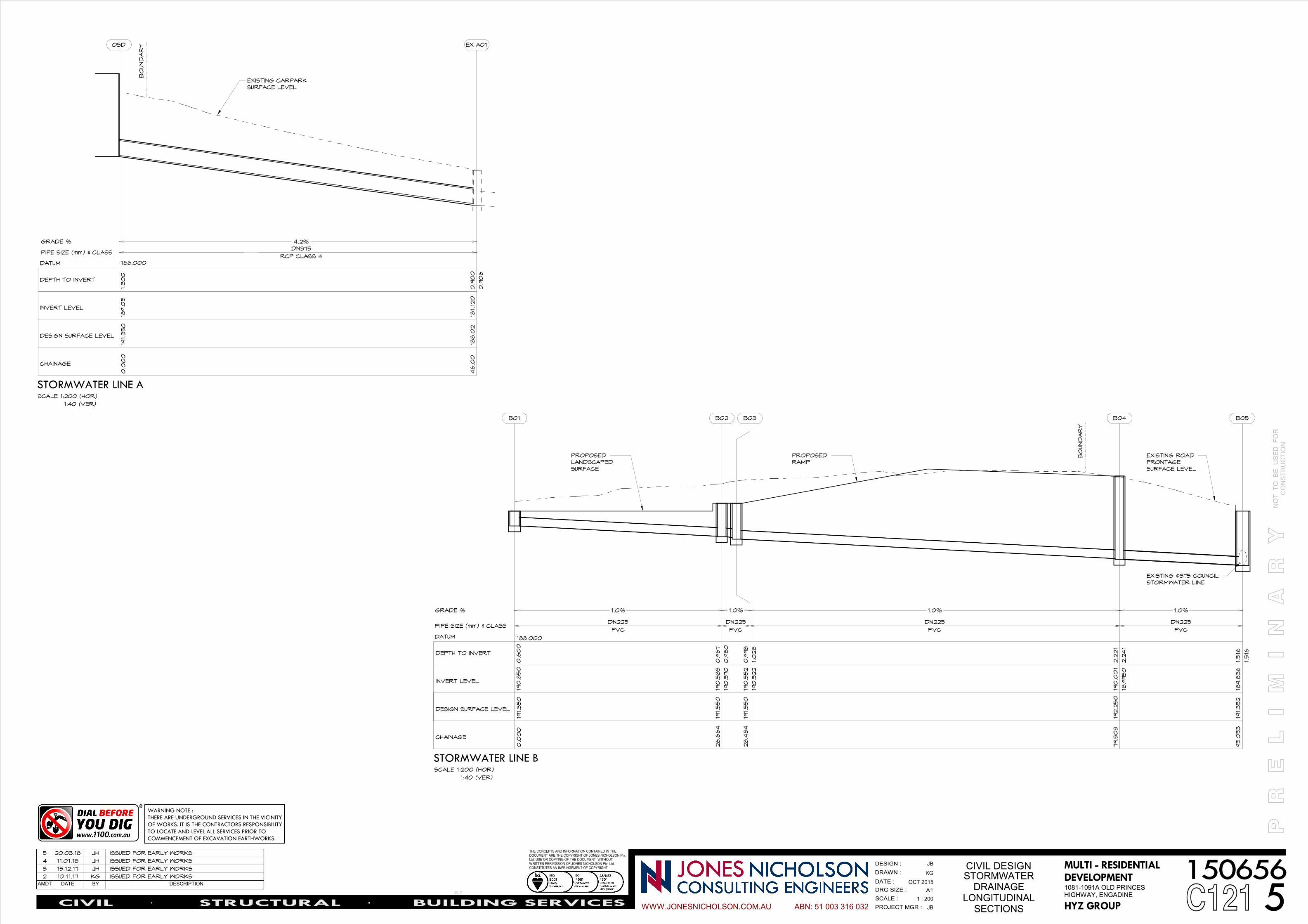
STORMWATER LINE A
DN375
4.2%
RCP CLASS 4
191.3
50
0.0
00
189.0
51.3
00
OSD
188.0
246.0
0181.120
0.9
06
0.9
00
EX A01
GRADE %
PIPE SIZE (mm) & CLASS
SCALE 1:200 (HOR)
1:40 (VER)
186.000
CHAINAGE
DESIGN SURFACE LEVEL
INVERT LEVEL
DEPTH TO INVERT
DATUM
BO
UND
AR
Y
EXISTING CARPARK
SURFACE LEVEL
DN225
1.0%
PVC
191.3
50
0.0
00
190
.850
0.6
00
B01
DN225
1.0%
PVC
191.5
50
26.6
64
190
.570
190
.583
0.9
80
0.9
67
B02
DN225
1.0%
PVC
191.5
50
28.4
84
190
.522
190
.552
1.0
28
0.9
98
B03 B04 B05
188.000
STORMWATER LINE BSCALE 1:200 (HOR)
1:40 (VER)
GRADE %
PIPE SIZE (mm) & CLASS
CHAINAGE
DESIGN SURFACE LEVEL
INVERT LEVEL
DEPTH TO INVERT
DATUM
EXISTING ø375 COUNCIL
STORMWATER LINE
BO
UND
AR
Y
EXISTING ROAD
FRONTAGE
SURFACE LEVEL
PROPOSED
LANDSCAPED
SURFACE
PROPOSED
RAMP
DN225
1.0%
PVC
192.2
50
79.3
03
18.9
950
190
.00
1
2.2
41
2.2
21
191.3
52
95.0
53
189.8
36
1.5
16
1.5
16
SCALE :
PROJECT MGR :
DATE :
DRAWN :
DRG SIZE :
DESIGN :
WWW.JONESNICHOLSON.COM.AU
P R
E
L I
M I
N A
R
Y
THE CONCEPTS AND INFORMATION CONTAINED IN THE DOCUMENT ARE THE COPYRIGHT OF JONES NICHOLSON Pty. Ltd. USE OR COPYING OF THE DOCUMENT WITHOUT WRITTEN PERMISSION OF JONES NICHOLSON Pty. Ltd. CONSTITUTES AN INFRINGEMENT OF COPYRIGHT
NO
T
TO
B
E
US
ED
F
OR
C
ON
ST
RU
CT
ION
A1
CIVIL DESIGN
ABN: 51 003 316 032CIVIL STRUCTURAL BUILDING SERVICES. . 5 1 : 200
STORMWATERDRAINAGE
LONGITUDINALSECTIONS C121
1081-1091A OLD PRINCESHIGHWAY, ENGADINE
MULTI - RESIDENTIAL
DEVELOPMENT
HYZ GROUP
JB
OCT 2015
JB
KG
2017
150656AMDT DATE BY DESCRIPTION
2 10.11.17 KG ISSUED FOR EARLY WORKS
3 15.12.17 JH ISSUED FOR EARLY WORKS
4 11.01.18 JH ISSUED FOR EARLY WORKS
5 20.03.18 JH ISSUED FOR EARLY WORKS
WARNING NOTE :
THERE ARE UNDERGROUND SERVICES IN THE VICINITY
OF WORKS. IT IS THE CONTRACTORS RESPONSIBILITY
TO LOCATE AND LEVEL ALL SERVICES PRIOR TO
COMMENCEMENT OF EXCAVATION EARTHWORKS.

SB
P.M.J
2730
189,050
SFL 189,050
189,050
189,050
C D E
8
9
10
11
STW ø225 @ 1.0% <
STW ø100 @ 1.0% <
STW ø225 @
1.5% <
STW ø300 @ 1.0% >
STW ø1
00 @
1.0%
<
RO1
900x900
ø100STW
1C125
900x900
GRATED LID
MIN 1130mm HIGH BLOCKWORK
CONCRETE WALLS AROUND
CARTRIDGE CHAMBER.
8x 690mm HIGH STORMFILTERS
ø375 RCP @ MIN. 2.5%
<
5kL RAIN WATER
TANK
3C125
2C125
FA
LL
FALL FALL
FALL
INLET PIPE TO BE SLUNG
FROM SOFFIT OF ROOF
OFF OSD TO WATER
QUALITY AREA
INLET PIPE TO BE SLUNG
FROM SOFFIT OF ROOF
OFF OSD TO WATER
QUALITY AREA
STW
ø100
@ 1.
0% <
8
INSTALL LYSAGHT
MAXIMESH RH3030
TRASH RACK
GALVANISED BEARING
ANGLE SURROUNDS.
TYPICAL.
GALVANISED STEP IRONS
IN EACH CHAMBER TO
COUNCIL SPECIFICATIONS.
298Ø Dia CONTROL
OUTLET ORIFICE TO
OVERFLOW
CHAMBER
1% CROSSFALL
- CONTRACTOR IS TO VERIFY THE LEVEL OF ALL EXISTING SERVICES PRIOR
TO COMMENCEMENT OF EXCAVATION FOR DRAINAGE.
REFER STRUCTURAL
ENGINEERS DRAWINGS FOR
SLAB AND WALL DETAILS
900 SQ. PRECAST
CONCRETE LID 191.90
V100:Q100 RL 190.75
375ø DIA OUTLET PIPE
20
0
STORMFILTER WALL CORE
FILLED BLOCKWORK (BY OTHERS)
225ø DIA INLET PIPE
RL 189.05
WEIR WALL TO WATER
QUALITY CHAMBER
SET TO RL190.25
225ø DIA INLET PIPE
WALL STRUCTURE BEHIND
SECTION EXCLUDED FOR
CLARITY
V100:Q100 RL 190.75
MIN. RL 190.75
300ø DIA INLET PIPE
MIN. RL 190.75
RL 190.25
RL 189.050
NOTE: FALL TANK
FLOOR TO ORIFICE
OUTLET AT MIN. 0.5%
NOTE: INLET PIPES TO BE SLUNG
TO ROOF TO WATER QUALITY
CHAMBER, AS PER OSD TANK
PLAN. PIPES NOT SHOWN IN
SECTION FOR CLARITY
8
RL 189.050
225ø DIA INLET PIPE
SCALE :
PROJECT MGR :
DATE :
DRAWN :
DRG SIZE :
DESIGN :
WWW.JONESNICHOLSON.COM.AU
P R
E
L I
M I
N A
R
Y
THE CONCEPTS AND INFORMATION CONTAINED IN THE DOCUMENT ARE THE COPYRIGHT OF JONES NICHOLSON Pty. Ltd. USE OR COPYING OF THE DOCUMENT WITHOUT WRITTEN PERMISSION OF JONES NICHOLSON Pty. Ltd. CONSTITUTES AN INFRINGEMENT OF COPYRIGHT
NO
T
TO
B
E
US
ED
F
OR
C
ON
ST
RU
CT
ION
A1
CIVIL DESIGN
ABN: 51 003 316 032CIVIL STRUCTURAL BUILDING SERVICES. . 4As indicated
OSD TANK PLAN
C1251081-1091A OLD PRINCESHIGHWAY, ENGADINE
MULTI - RESIDENTIAL
DEVELOPMENT
HYZ GROUP
JB
OCT 2015
JB
KG
2017
150656AMDT DATE BY DESCRIPTION
1 20.03.18 JH ISSUED FOR EARLY WORKS
2 22.03.18 JH ISSUED FOR EARLY WORKS
3 9.05.18 JH ISSUED FOR EARLY WORKS
4 10.05.18 JH ISSUED FOR EARLY WORKS
SCALE 1 : 100
OSD TANK PLAN
SECTIONSCALE 1 : 20 C125
1
SECTIONSCALE 1 : 20 C125
3SECTIONSCALE 1 : 20 C125
2

10 May 2018 Our Ref: CLTR-20150656.04C
Page 6 of 6
APPENDIX B – Updated Assessment Report

SUTHERLAND OFFICE LOCATIONS: SYDNEY-CBD SUTHERLAND WOLLONGONG NOWRA GOULBURN PICTON SINGLETON ABN 51 003 316 032 Suite 45, 40-44 Belmont Street, SUTHERLAND NSW 2232 PO Box 477, SUTHERLAND NSW 1499
Tel: 02 9521 3088 Fax: 02 9521 3066 Email: [email protected] www.jonesnicholson.com.au
Page 1 of X
20 April 2018 Our Ref: CLTR-20150656.03B The Gallery at Engadine Pty Ltd Suite 1, Level 9, Strathfield Plaza 11 The Boulevarde Strathfield NSW 2135 ATTENTION: MR CRAIG BENNETT Dear Craig, DEVELOPMENT DESCRIPTION: NEW RESIDENTIAL DEVELOPMENT – “THE GALLERY” CLIENT: THE GALLERY AT ENGADINE PTY LTD LOCATION: 1081-1089 OLD PRINCES HIGHWAY
ENGADINE NSW 2233
Jones Nicholson has been engaged by The Gallery at Engadine Pty Ltd to assess the impact the that the proposed residential development at the above-mentioned site, will have on the existing Council stormwater trunk drainage network. In completing the stormwater assessment of the existing supporting infrastructure and the design of the development stormwater infrastructure, Jones Nicholson reviewed and designed in accordance with relevant Australian Standards and Council policy. To ensure the design is in accordance with Council stormwater requirements, Jones Nicholson has also assessed water quality requirements and introduced measures in the design to ensure compliance. STORMWATER SITE DISCHARGE Currently, the stormwater of the majority of the neighbouring Telstra property, flows through the undeveloped site to the Myall Place drainage network in the neighbouring carpark facility. A majority of the proposed development site also flows to the Myall Place drainage network also. The remaining area of the proposed site, which contains existing commercial buildings (1086 – 1089 Old Princes Highway) along the Old Princes Highway frontage, flows to the Old Princes Highway Council drainage network. The proposed development (1081 – 1089 Old Princes Highway) will have all stormwater on site collected and flow to an onsite detention (OSD) tank within the property boundary. As the neighbouring Telstra property runoff will not be permitted to flow to the Myall Place drainage network because of the proposed development, a stormwater pit and pipe network will need to be constructed to divert this to the Old Princes Highway network. Details of this proposed construction is within Appendix A of this letter. Existing runoff from the proposed development site in the location of the existing commercial buildings will now be diverted to the OSD tank and have flow controlled to the Myall Place drainage network via orifice.

20 April 2018 Our Ref: CLTR-20150656.03B
Page 2 of 6
The site stormwater runoff in various storm events has been assessed for the site in the pre and post development state. The following table summarized the runoff to the Myall Place and Old Princes Highway stormwater infrastructure. PRE-DEVELOPMENT FLOW TO MYALL PLACE Telstra Catchment Flowing to Myall Place = 863m2
5yr ARI runoff = 34.0 L/s 100yr ARI runoff = 55.1 L/s
Development Site Catchment to Myall Place = 4,154m2 (Note: roof runoff of some of existing commercial buildings on this site flows into the Old Princes Highway network)
5yr ARI runoff = 179.0 L/s 100yr ARI runoff = 305.0 L/s
Total runoff to Myall Place pre-development is 213 L/s in the 5yr ARI storm event and 360.1 L/s in the 100yr ARI event. POST DEVELOPMENT FLOW TO MYALL PLACE Development to Site to Myall Place = 5,288 m2
5yr ARI flow = 175 L/s (controlled via orifice) 100yr ARI flow = 288 L/s (controlled via weir)
Note: Development flow controlled via 22.8m3 OSD tank with 260mm diameter orifice. OSD sized using DRAINS stormwater modelling software. DRAINS model provided. PRE-DEVELOPMENT FLOW TO OLD PRINCES HIGHWAY No flow from the existing Telstra site enters the Old Princes Highway stormwater network. Development Site Catchment to Old Princes Highway = 1,134 m2 (roof runoff of some of existing commercial buildings)
5yr ARI runoff = 40.1 L/s 100yr ARI runoff = 64.9 L/s
POST DEVELOPMENT FLOW TO OLD PRINCES HIGHWAY Additional Telstra Catchment due to diversion to Old Princes Highway = 863 m2
5yr ARI flow = 34.0 L/s 100yr ARI flow = 55.1 L/s
No flow from the proposed development site will enter the Old Princes Highway stormwater network. Based on the above calculations, the Myall Place and Old Princes Highway stormwater networks will have less runoff enter their systems in the post development state, compared to the predeveloped state. This is due to run off for the proposed development adequately managing flow through the onsite detention tank

20 April 2018 Our Ref: CLTR-20150656.03B
Page 3 of 6
and orifice before discharging to the Myall Place stormwater network. As there is no increase on the existing Council stormwater network, no capacity upgrades will be required. The connection of WATER QUALITY MANAGEMENT To ensure compliance with Sutherland Shire Council and DA conditions, all urban stormwater runoff has been directed to the proposed on-site detention tank via the site drainage network. This can be seen in Appendix A of this report. Within the OSD tank, stormwater filter cartridges manage the runoff to required levels before discharging to the kerb. In order to meet Council’s water quality targets specified within the WSUD policy, the proposed development stormwater system requires the following elements to treat runoff so that it meets quality targets:
Roof water to rainwater tank of 5kL. It is proposed that 256kL/yr will be reused for irrigation purposes. Water quality to OSD tank to be provided by the installation of eight (8) filtration cartridges such as Stormwater 360’s PSORB cartridges (or approved equivalent) in the tank. Details of these cartridges proposed for the OSD can be found in Appendix B. Water quality to ground level to be provided by installation of treatment device such as Stormwater 360’s Enviropods (or approved equivalent) to eleven (11) of the external grated inlet pits, which lead to discharging to the OSD tank.
The following nodes and areas were used for the MUSIC model, along with rainfall and model parameters specified within Chapter 37 of Sutherland Shire Council’s Development Control Plan 2015.
Figure 3 – MUSIC model nodes and areas within model.
The above model and treatment devices, lead to the following post development reduction targets which satisfy Sutherland Shire Council’s WSUD technical specifications:
Figure 4 - Post Development load targets

20 April 2018 Our Ref: CLTR-20150656.03B
Page 4 of 6
A MUSIC model has been provided as verification of the above results. Should you need any additional information from us, please feel free to contact the undersigned on 02 9521 3088. For and on behalf of Jones Nicholson Pty Ltd
Jackson Bramley BE (Civil), MIEAust Civil/Structural Project Engineer