cluster-based communications system for immediate post-disaster
TRANSCRIPT

Cluster-based Communications System for Immediate Post-disaster Scenario
Sonia Majid and Kazi Ahmed Asian Institute of Technology, Bangkok, Thailand
Email: {sonia.majid, kahmed}@ait.ac.th
Abstract—Communication facilities can totally be destroyed by natural and / or manmade disasters. A critical problem after disaster is getting the first hand knowledge of the destructions and also establishing some communication links among the survivors. This paper focuses on the vital need for providing communications facility to the victims, immediately after the disaster and prior to the arrival of rescue teams. The proposed novel approach in emergency communications enables survivors to communicate among themselves and help each other. Here, the idea of a self-organizing network is put forward, which makes use of available network resources formally occupied by the destroyed and / or damaged telecommunications’ infrastructure. In our post-disaster scenario, mobile nodes establish a self-organizing / ad hoc network which provides critical level of communications among disaster victims needed at that time and consequently tries to merge with some surviving telecommunications infrastructure and / or network deployed by rescue teams. The outcome of this paper is a fundamentally novel idea for immediate post-disaster communications. This idea is tested through some network survivability measures and hypothesis testing. We also test the working of this ad hoc network through simulation for post-disaster scenarios of partially and fully destroyed networks. The results obtained are found to be satisfactory and within acceptable limits of ad hoc networks. Index Terms—post-disaster communications, emergency communications, self-organizing network, disaster scenarios
I. INTRODUCTION
During and after a disaster many communities are often cutoff from their national communications infrastructure, leaving the entire nation in a state of anxiety. The absence of first hand knowledge regarding the survivors and dead causes enormous suffering to the whole nation. Disaster response and recovery needs timely co-ordinations to minimize the loss in areas where telecommunications system is no longer operational. Examples in our immediate experiences include the South East Asia tsunami, hurricanes Katrina and Rita in the USA, the South Asian earthquake in Pakistan, India, and Afghanistan, mudslides in Guatemala, natural disasters in Indonesia and in many other places. Some of the ideas to deal with emergency communications, both in pre-disaster / early warning systems and post-disaster
communications, are discussed in [1]. In [2], a cross-layer framework to deal with emergency situations is presented. In this paper we focus on providing critical level of communications among disaster victims needed immediately after the disaster and prior to the arrival of rescue teams.
It is observed in [3] that 50% of deaths occur within first two hours after the disaster. Thus, the motive behind such provision is to save as many lives as possible by allowing the survivors to communicate among themselves and help each other.
This paper is organized as follows. Section II discusses the previous work on networks proposed for post-disaster communications. Section III discusses our proposed establishment of Disaster Response Network (DRN) while, section IV presents the routing and MAC protocols used by the DRN. We propose some hypothesis and analyze the simulation results for the DRN in section V. The conclusions are drawn in the last section.
II. RELATED WORK
Because of the uncertainty of the infrastructure-based networks, an ad hoc network is regarded as a promising solution by many researchers in an emergency situation [4-5]. In [4], a hybrid wireless network scheme for emergency communications proposes combination of ad hoc networks with a centralized network to maintain connections. The work is based on the concept that a mobile terminal switches to ad hoc mode to access a Base Station (BS) via multi-hopping, when a link between BS and terminal is disconnected. But it is not mentioned that how the switching of mode is triggered by the mobile node. Some have designed solutions for specific post-disaster applications [6-8], for example, in trains, underground mines etc. where, some limited communication links are destroyed, but nearby infrastructure is still interacting. The use of a rapid deployable ‘last mile’ broadband wireless high speed communications system for emergency communications is proposed in [9].
In [5,10], emergency networks based on mounted antennas (BS) either on vehicles or on top of non-destroyed buildings to provide communications, are presented. In [11-12], MAC layer protocols for mobile ad hoc networks are discussed for emergency situations. In [13-14] mechanism for the identification of victims location in an emergency situation is demonstrated. In all
Manuscript received: September 24, 2008; Manuscript revised: February 17, 2009; Manuscript accepted: March 31, 2009.
JOURNAL OF COMMUNICATIONS, VOL. 4, NO. 5, JUNE 2009 307
© 2009 ACADEMY PUBLISHER

these researches, solutions are implemented after the rescue teams have reached the disaster affected areas. In this paper we present a self-organizing network which helps victims to communicate among them, prior to the arrival of rescue teams and / or parties involved in response activities.
In this paper we propose that the mobile devices of disaster victims e.g., cellular mobile handsets etc. form a Disaster Response Network (DRN). This network is self-organized and established to allow disaster victims to perform some basic communications (e.g., voice communications and short messaging) among them, before the arrival of rescue teams. We assume that the Mobile handSets (MS) are having Emergency Communications Component (ECC) [2], which is designed for controlling all the additional activities we propose for the immediate post-disaster scenario. We further assume that the MSs need to be in emergency mode to perform the activities of our proposed DRN. We
investigated the possible technological solutions to switch a MS from normal to emergency mode in [15].
III. ESTABLISHMENT OF DISASTER RESPONSE NETWORK
We broadly categorize the establishment of ad hoc networks in two ways; peer-to-peer and clustered based. We use the clustering approach for the establishment of the Disaster Response Network (DRN) as discussed below.
A. Clustering Approach
This approach provides three basic benefits: firstly, DRN appears smaller and stable to each mobile node [16]; secondly, the DRN resources are re-used in different clusters enabling high capacity of overall network [17-18]; and finally, using the clustering approach for the DRN gives efficient routing and hence DRN is scalable. Some of the very useful clustering algorithms which have been proposed for multi-hop mobile ad hoc networks [19-21] are listed in Table I.
TABLE I.
CLUSTER-BASED MANET PROTOCOLS FOR MULTI-HOP COMMUNICATIONS Protocol Objective Description
Distributed Dynamic Clustering Algorithm (DDCA) [19]
Adjusting the dominant routing mechanisms based on network’s mobility behavior; minimize the influence of mobile nodes’ movement on cluster topology updates; provide robust and efficient routing
CH does not need to have any specific attributes in neighborhood; if a mobile node does not receive any JoinResponse message after a certain period of time it creates a new cluster just covering itself and becomes CH; mobile node can join a cluster if it has a mutual path to satisfy ( , )tα 1 criteria.
Degree-Load-Balancing Clustering (DLBC) [20]
Limiting the number of mobile nodes (to a predefined value) forming a cluster to maintain balance in traffic load among clusters
Periodically a clustering scheme is run to keep the number of mobile nodes in
each cluster around the system parameter ED 2, if the difference between E D and the number of mobile nodes CH is currently serving, exceeds some
value _M a x D elta , CH becomes an ordinary node.
ID Load Balancing Clustering (IDLBC) [20]
Limiting the time a mobile node can serve as CH continuously to avoid possible node failures (due to excessive serving as CH)
Each mobile node has a variable Virtual ID (VID) which was initially set to its ID number; nodes with highest VIDs in their local becomes the CHs. When a CH exhausts its duration budget by continuously serving for
_M a x C o u n t , it resets its VID to zero and becomes a non-clusterhead
node.
Adaptive Multi-hop Clustering (AMC) [21]
Limiting the number of nodes that a cluster can handle within a predefined range, to balance the traffic load in each cluster
No description of initial construction of clusters is given in the AMC protocol; for cluster maintenance each mobile node periodically broadcasts its information within its cluster; if the number of members in a cluster is less than L 3, a merge mechanism is performed however, if the number of
members in a cluster is greater than U a division mechanism is invoked.
Hybrid Cluster Routing (HCR) [21]
Acquiring balance between routing overhead and latency delay for large mobile ad hoc networks
Network is designed in two-tier structure for routing; on demand routing mechanism is used for intra-cluster and proactive routing is used for inter-cluster; CH is elected based on the degree of node i.e., number of neighboring nodes.
1 ( , )tα criteria indicate that every mobile node in a cluster has a path to every other node that will be available over some time period t with a
probability α≥ regardless of the hop distance between them. 2 ED indicates the optimum number of mobile nodes that a CH can handle. 3 Upper and lower bound (U and L ) defined on the number of cluster members that a CH can handle
In post-disaster scenario we propose the process of establishment of DRN using clustered based ad hoc network approach, based on Hybrid Cluster Routing (HCR) [21]. For the Disaster Response Network (DRN) we consider mobile node’s degree of freedom along with the battery power as the selection criteria for the cluster head. The mobile nodes under the DRN are grouped in five classes (temporary states for each MS):
Cluster Head (CH) node: A CH is a node which is responsible for Intra-clustering activities and maintaining Inter-cluster topology information for the DRN.
Standby cluster Head (SH) node: The mobile node having the maximum battery power among all the member nodes (other than the CH) of a cluster, is regarded as the SH node. If a new node registers to
308 JOURNAL OF COMMUNICATIONS, VOL. 4, NO. 5, JUNE 2009
© 2009 ACADEMY PUBLISHER

the cluster, the CH compares the battery power of the existing standby cluster head with the battery power of the new member node. If the battery power of the existing SH node is greater than that of the new member node, no change takes place. Otherwise, the new node becomes the new SH and the previous SH node becomes the ordinary member of the cluster.
Unregistered node (UN): A mobile node becomes a UN just after switching to emergency mode and before being the member of the DRN.
Cluster Member (CM) node: A CM is a node having membership of only one cluster head in the DRN.
Cluster Gateway (CG) node: A node having membership of more than one cluster is the CG node. This node acts as a gateway between these clusters within the DRN.
The UNs need to register with any of the CHs in order to become part of the DRN. To limit the number of clusters in the DRN, we define the cluster radius through parameter ‘k’. A CH is able to register nodes within its k-hop communication and PHY range. The following section explains the process of selection of the CH and registering of the UN in detail.
B. Selection of Cluster Head and Node Registration Mechanism
When a mobile node switches its mode to emergency, it remains as UN until it registers with any of the cluster or becomes a CH itself. To register with any CH, the UN starts listening to the neighbor’s broadcasts. If a UN ‘x’ does not receive any Registration Beacon (RB) message from nearby CHs working under the DRN for a pre-defined registration time period ( )rT , then it declares
itself as a CH and forms a cluster. This cluster initially covers only one node i.e., the CH itself. The CH node becomes a part of the DRN and starts sending periodic RB messages to neighboring nodes to invite registration of the UNs within its k-hop range. Any UN, which receives the RB message from the CH, tries to register with this CH, using the following mechanism.
When a UN ‘x’ receives a RB from the CH ‘y’, it requests to register with this
yC H by sending a
registration-request-message (REG_REQ(x, P(x)). This message includes id of the UN and its battery power measurement P(x). A hop count field is also added in the packet format to help the CH in identifying its hop distance from the concerned UN.
On receiving the registration request from the UN ‘x’,
the yCH checks the hop count of the received packet. If
the hop count of UN ‘x’ (HCNT(x)) is more than k-hops,
then the yCH sends registration-not-confirm
(REG_NCFM) message to the UN ‘x’, else it registers the UN ‘x’ by sending the registration-confirm-message (REG_CFM). If the UN ‘x’ receives a (REG_NCFM), it
waits for another rT period, to get the RB broadcast by
any other CH. If the RB is not received (within the rT
period), the UN ‘x’ declares itself a CH and forms a 1-
node cluster. On contrary, if the (REG_CFM) is received by the UN ‘x’, it changes its status to CM and becomes the part of the DRN. Fig. 1 illustrates the flow of node registration mechanism.
Figure 1. Flow diagram of node registration mechanism
After registration of the new cluster member xCM , the
yCH compares the battery power of the xCM with that
of the standby cluster head zSH . If the battery power of
the zSH is less than that of the xCM , then the xCM
becomes the standby cluster head xSH and the node ‘z’
becomes the ordinary cluster member zCM . This process
is described by the following piece of code where, ‘x’ is the UN, ‘y’ is the CH and ‘z’ is the SH:
( ( ) ) )
{
( _ );
( ( ) ( ))
{
C h a n g e _ S ta tu s (x ,S H ) ;
C h a n g e _ S ta tu s (z ,C M );
}
}
{
( _ ) ;
/ /< w
I f H C N T x k th e n
s e n d R E G C F M
If P z P x th e n
e ls e
s e n d R E G N C F M
≤
<
a i t fo r R e g is tra t io n B e a c o n (R B ) m e s s s a g e fro m
/ /a n y o th e r C H n o d e >
}
JOURNAL OF COMMUNICATIONS, VOL. 4, NO. 5, JUNE 2009 309
© 2009 ACADEMY PUBLISHER

Under the DRN, a cluster member uCM which is able
to hear the RB message from more than one CHs,
changes its state to the cluster gateway uCG , and
updates its current status to the CHs by sending a change-
status-message (Change_Status(u,CG)). The yCH once
selected, remains as the CH, until its battery power falls
below the power threshold ( )THP and also the battery
power of the yCH is less then the battery power of the
xSH . This power check is done periodically. Fig. 2
illustrates the flow of periodic power check for CH selection mechanism.
Figure 2. Flow diagram of periodic power check cluster head
selection mechanism One of the very vital factors which influence the
success of the DRN is the size of the cluster. We define the mobile handsets qualifying to be the members of the cluster of a single cluster head as:
( ) , ( , )xS i i i V hop x i k= ∀ ∈ ∃ ≤ (1)
where, V is the set of all mobile handsets working under
emergency mode, ( , )hop x i is the number of hops
between xCH and node i , k is the cluster radius
(number of hops) and ( )xS i is the set of mobile handsets
forming the cluster under the xCH .
The size of the cluster depends on cluster density. The cluster density is defined to be the average number of CHs per unit area [22]. Eq. (1) shows that the cluster density is highly dependent on the factor k . Other parameters which we have considered for the calculation of cluster density are the MS node’s degree of freedom (i.e., number of potential neighboring nodes) and the battery power. Assuming a simple uniform distribution of the MS nodes in the disaster affected area, the node
density ( )ρ for V nodes distributed in A disaster
affected area is: V
Aρ = (2)
And the cluster density ( )cρ is considered as:
{ }c
E CH
Aρ = (3)
where, { }E CH is the expected number of CHs per
unit area. The probability that a randomly chosen node is a CH is:
{ }( ) cE CH
P CHV
ρρ
= = (4)
We consider that MS nodes roam about the disaster affected area in a random fashion. We model the registration of an MS node with the cluster, as a collection of independent random variables indexed by intervals. Consequently, we use the random point process. The expected degree of freedom of an MS node in the disaster affected area with V nodes working in emergency mode is:
2{ }F reedomE D eg kρ π= (5)
Moreover, we consider that there is an exponential rate ( )λ of decrease of the battery power of an MS node
working in emergency mode. Therefore, the expected decrease in the battery consumption of an MS node is:
1{ }B a tte ryE P
λ= (6)
Using Eq. (5) and Eq. (6), the cluster density is found to be:
2 1c
V
k
λρλ ρ π
=+
(7)
For simplicity, we take 2k = throughout the text. Following section explains the topology of the DRN in detail.
C. Network Topology
We maintain the topology of the Disaster Response Network (DRN) at two levels i.e., at Intra-cluster level and Inter-cluster level.
1) Intra-cluster Topology: In DRN, each CH maintains a list of all its member nodes in a table known as Local Network Topology (LNT) table. The LNT table contains identity of all its members along with their status, battery power level, and utilization factor. Each member of the cluster periodically sends the information regarding itself to the CH. The CH updates its LNT table using these periodic updates and analyzes the updated LNT table for two things: Ensuring that the SH is the one with maximum
battery power (among all its member nodes). If this is not the case, then the member node with maximum battery power is regarded as the SH and the status of the previous SH is changed to the status of ordinary CM.
To track changes in the local network topology i.e., Intra-cluster topology. Fig. 3 shows the example of the Local Network Topology (LNT) table.
310 JOURNAL OF COMMUNICATIONS, VOL. 4, NO. 5, JUNE 2009
© 2009 ACADEMY PUBLISHER

2) Inter-cluster Topology: The Inter-cluster topology information is maintained by each CH in a table known as Global Network Topology (GNT) table. The GNT table contains the list of all the CHs in the DRN along with the identities of its member nodes; we may also see the GNT table as the connected graph for the DRN (Fig. 4). Each CH updates its GNT table whenever a change in its local topology of the cluster takes place. To prevent fast dissipation of CH node’s battery power, one possible solution might be of sharing the load of GNT table update between the CH and SH nodes. However, in this study GNT table update is handled by CH only. The updated GNT table is then communicated to all other CHs to maintain a synchronized GNT within the whole DRN.
Figure 3. Example of Local Network Topology (LNT) table
Figure 4. Example of Global Network Topology (GNT)
The updated version of GNT table also helps the CH in
discovering routes for Inter-cluster communications. Our proposed DRN uses the features of cognitive radio for finding available resources for successful communications. The cluster head (CH) is also responsible for assigning and maintaining the addresses to all its cluster members. The CH node uses its international mobile equipment identifier (IMEI) number, to uniquely identify its own cluster and follow the sequential addressing scheme for its cluster members. The sequence of addressing is in the order of registration of MS nodes to the CH.
The subsection D explains the cooperative spectrum sensing technique implemented in the DRN, and how the distributed sensed spectrum holes are combined at cluster level to provide interference free communications needed for critical situations like post-disaster scenarios.
D. Cooperative Spectrum Scanning for DRN
One of the challenging tasks in post-disaster scenario is to determine how the mobile handsets of the disaster victims handle the distributed and dynamic spectrum resources. In the proposed DRN, a two stage spectrum scanning technique (Fig.5) is used for efficient spectrum management in the disaster affected area.
1) Local Spectrum Sensing
The spatially distributed mobile handsets (in emergency mode) of the disaster victims scan the spectrum periodically after every spectrum detection time ( )SDT . Each mobile handset involved in the spectrum
scanning process analyzes the scanned information and identifies the spectrum holes. We use the energy detection technique for spectrum scanning. The spectrum activity is performed across [23] the frequency band of previously existed cellular network (which is destroyed by the disaster). Each handset scans n frequency channels over each spectrum sensing period ( )ScanT . The
frequency channels to be scanned by xC M are
determined by the following relationship:
{ }1
for ( 0 : 1)
( ) * x
i n
F i f i ε= −
= + (8)
where, xF represents the n frequency channels to be
scanned by a mobile handset ‘x’ over ( )ScanT and ε is a
constant, whose value is randomly generated by each CH, such that:
B W ( 1)n ε≤ − (9)
where, B W is the total bandwidth available for scanning.
Figure 5. Flow diagram for two-phase spectrum scanning
The result of spectrum scanning is then communicated
to the CH using a control channel. The CH combines these time-variant spectrum scanned information, sensed by the CMs, which are geographically distributed in the disaster affected area. This mechanism is explained as follows:
2) Cooperative Spectrum Scanning To combine the spectrum scanned information (for
different frequency channels) for forming the list of available frequency channels (AFL) (to be used within the whole cluster in the DRN), we introduce a serial switch model (Fig. 6). We represent the locally sensed
JOURNAL OF COMMUNICATIONS, VOL. 4, NO. 5, JUNE 2009 311
© 2009 ACADEMY PUBLISHER

information (V(f)) for the frequency channel (f) as a switch, which is open or closed depending on the sensed information.
A spectrum hole, which is commonly detected by all the switches and for which the model output is 1, is added to the AFL for the CM i.e.,
( )1
( 0 : )
, ;n
y s ll
fo r j N
A p p en d A F L O=
=
⎛ ⎞∏⎜ ⎟⎝ ⎠
(10)
where, yA F L is the available frequency channels,
sensed by the yC H ;
( )S lO is the output of thl switch
and N is the number of switches (‘N-1’ mobile handsets and ‘1’ CH, involved in scanning process).
Figure 6. Serial switch model for cooperative spectrum scanning at
the CH Under the DRN, we limit the spectrum sensing or the
identification of available spectrum resources to CH and to the nodes at k-hop level of the cluster. The energy consumption of mobile handsets i.e., from 1-hop to (k-1) hop levels, is reduced as these mobile handsets are involved in spectrum scanning process. The CH is responsible for assigning the frequency channel for all the nodes (within its k-hop cluster) willing to communicate within or outside the cluster.
If the signal level of the primary user (PU) in the cognitive radio scenario is found to be strong enough to cover the k-hop communication range of the CH, it broadcasts a message to set access flag to FALSE and switch its mode to normal cellular functions. On receiving the message to set access flag to FALSE, the mobile handsets within that cluster switches back to the normal mode and start communicating via the available cellular system. On the other hand, if the PU’s signal strength is not found to be strong enough to provide coverage to the whole k-hop cluster, then the CH tries to merge with PU’s network and acts as a cooperative relay node. It then relays the information from our DRN to the Disaster Information Center (DIC) through the PU network and forms a hybrid DRN.
E. Hybrid DRN
We propose the use of hybrid DRN in situations where the communications infrastructure in the disaster affected area is partially destroyed or not functioning. The hybrid DRN is established by merging our proposed DRN with any adjacent surviving base station and / or base stations installed by rescue teams, as shown in Fig. 8. We refer to these surviving infrastructure nodes as PUs. When a PU is detected by our DRN and the signal strength of the PU is not strong enough to provide coverage to the entire k-hop cluster, then the CH links itself to the base station directly or via an active node of the adjacent cell and provides a relay link for rest of the nodes in the cluster.
In Fig. 8 the hC H links itself to the PU base station.
The cluster member jC M within the coverage range of
the PU network unregisters itself from the cluster, and switches its mode from emergency to normal. However, the cluster head hCH provides a relay link for the rest of
the CMs within its cluster but not under the coverage range of the PU base station i.e., iCM ,
gCM , fCG
and kC G .
Moreover, using the Inter-cluster route discovery mechanism, a route from other clusters having
cC H and
mC H to the PU network can be revealed, hence
providing PU network access (centralized network e.g., base station access) to all connected clusters. Fig. 7 illustrates the hybrid DRN.
Primary User
Network
Figure 7. Hybrid DRN
The proposed network is available as long as the
battery power of the MS nodes (forming the DRN) remains and/or the network service providers re-establishes the destroyed network facilities and components. The network protocols used in the DRN are explained in section IV.
IV. DISASTER RESPONSE NETWORK (DRN) PROTOCOLS
This section presents routing and MAC protocols for the DRN. In subsection A, the routing protocol used is explained.
312 JOURNAL OF COMMUNICATIONS, VOL. 4, NO. 5, JUNE 2009
© 2009 ACADEMY PUBLISHER
A. Routing Protocol
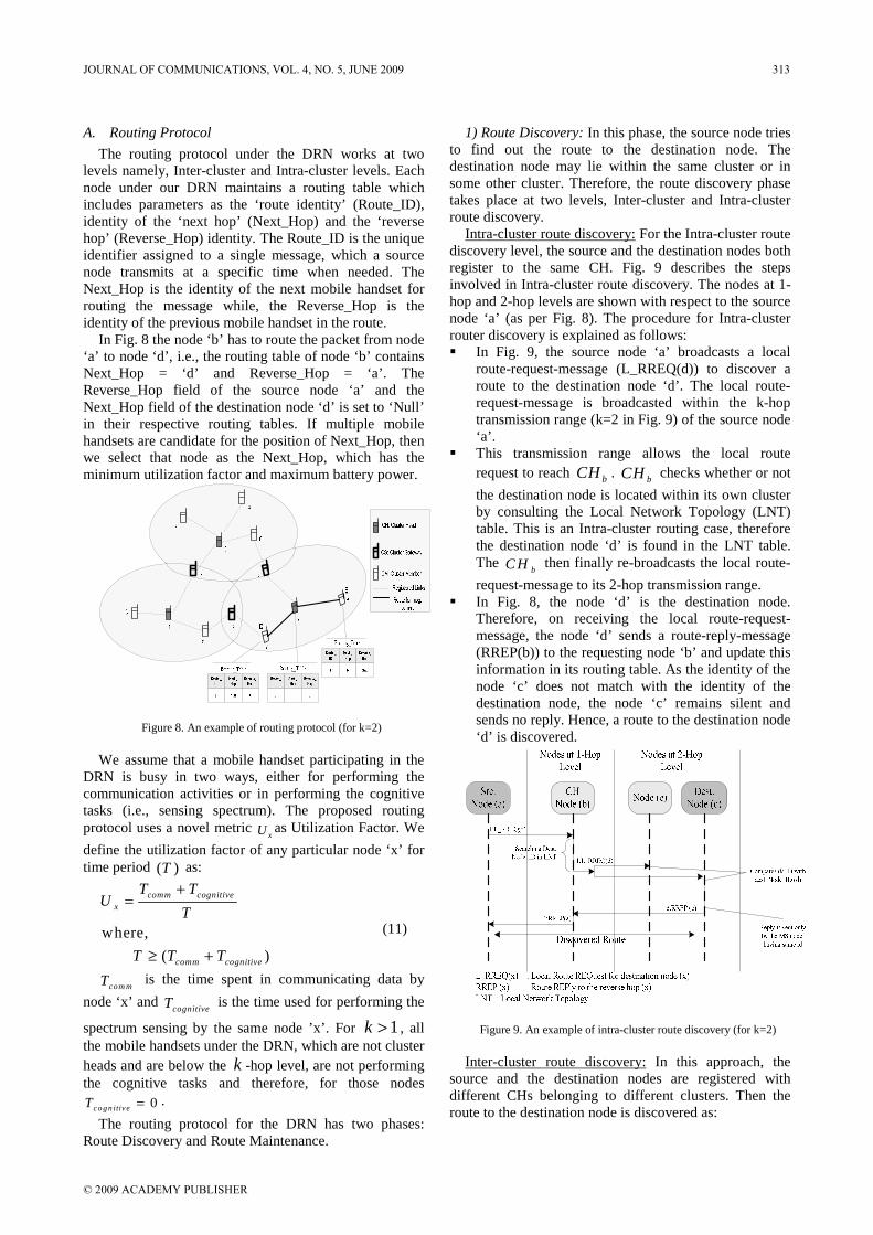
The routing protocol under the DRN works at two levels namely, Inter-cluster and Intra-cluster levels. Each node under our DRN maintains a routing table which includes parameters as the ‘route identity’ (Route_ID), identity of the ‘next hop’ (Next_Hop) and the ‘reverse hop’ (Reverse_Hop) identity. The Route_ID is the unique identifier assigned to a single message, which a source node transmits at a specific time when needed. The Next_Hop is the identity of the next mobile handset for routing the message while, the Reverse_Hop is the identity of the previous mobile handset in the route.
In Fig. 8 the node ‘b’ has to route the packet from node ‘a’ to node ‘d’, i.e., the routing table of node ‘b’ contains Next_Hop = ‘d’ and Reverse_Hop = ‘a’. The Reverse_Hop field of the source node ‘a’ and the Next_Hop field of the destination node ‘d’ is set to ‘Null’ in their respective routing tables. If multiple mobile handsets are candidate for the position of Next_Hop, then we select that node as the Next_Hop, which has the minimum utilization factor and maximum battery power.
Figure 8. An example of routing protocol (for k=2)
We assume that a mobile handset participating in the
DRN is busy in two ways, either for performing the communication activities or in performing the cognitive tasks (i.e., sensing spectrum). The proposed routing protocol uses a novel metric
xU as Utilization Factor. We
define the utilization factor of any particular node ‘x’ for time period ( )T as:
where,
( )
comm cognitivex
comm cognitive
T TU
T
T T T
+=
≥ +
(11)
com mT is the time spent in communicating data by
node ‘x’ and cognitiveT is the time used for performing the
spectrum sensing by the same node ’x’. For 1k > , all the mobile handsets under the DRN, which are not cluster heads and are below the k -hop level, are not performing the cognitive tasks and therefore, for those nodes
0c o g n itiv eT = .
The routing protocol for the DRN has two phases: Route Discovery and Route Maintenance.
1) Route Discovery: In this phase, the source node tries to find out the route to the destination node. The destination node may lie within the same cluster or in some other cluster. Therefore, the route discovery phase takes place at two levels, Inter-cluster and Intra-cluster route discovery.
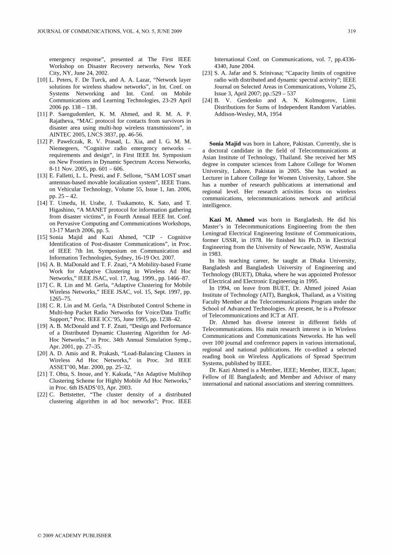
Intra-cluster route discovery: For the Intra-cluster route discovery level, the source and the destination nodes both register to the same CH. Fig. 9 describes the steps involved in Intra-cluster route discovery. The nodes at 1-hop and 2-hop levels are shown with respect to the source node ‘a’ (as per Fig. 8). The procedure for Intra-cluster router discovery is explained as follows: In Fig. 9, the source node ‘a’ broadcasts a local
route-request-message (L_RREQ(d)) to discover a route to the destination node ‘d’. The local route-request-message is broadcasted within the k-hop transmission range (k=2 in Fig. 9) of the source node ‘a’.
This transmission range allows the local route request to reach bCH . bCH checks whether or not
the destination node is located within its own cluster by consulting the Local Network Topology (LNT) table. This is an Intra-cluster routing case, therefore the destination node ‘d’ is found in the LNT table. The
bC H then finally re-broadcasts the local route-
request-message to its 2-hop transmission range. In Fig. 8, the node ‘d’ is the destination node.
Therefore, on receiving the local route-request-message, the node ‘d’ sends a route-reply-message (RREP(b)) to the requesting node ‘b’ and update this information in its routing table. As the identity of the node ‘c’ does not match with the identity of the destination node, the node ‘c’ remains silent and sends no reply. Hence, a route to the destination node ‘d’ is discovered.
Figure 9. An example of intra-cluster route discovery (for k=2)
Inter-cluster route discovery: In this approach, the
source and the destination nodes are registered with different CHs belonging to different clusters. Then the route to the destination node is discovered as:
JOURNAL OF COMMUNICATIONS, VOL. 4, NO. 5, JUNE 2009 313
© 2009 ACADEMY PUBLISHER

Similar to the Intra-cluster discovery, the source node ‘a’ (in Fig. 10) broadcasts a local route-request-message (L_RREQ(f)) to discover a route to the destination node, e.g., ‘f’. The local route-request-message is broadcasted within the k-hop transmission range (k=2 in Fig. 10) of the source node ‘a’.
The bC H checks whether the destination node is
located within its own cluster or not by consulting the LNT table. As this is an Inter-cluster routing case, the destination node ‘f’ is not found in the LNT table. The
bC H then sends the Global Network
Topology (GNT) table information to the source node ‘a’.
The source node ‘a’ by consulting the GNT table, finds a CG which is at the minimum distance from the destination node ‘f’. In our case (Fig. 8) it is node ‘c’ i.e.,
cC G . The source node ‘a’ then broadcasts
the global route-request-message (G_RREQ(c,f)) upto its k-hop transmission range. The global route-request-message is used to discover the route to the
cCG and help this CG to discover the route to the
destination node ‘f’ in its adjacent cluster. On receiving the global route-request-message, the
cCG broadcasts the local route-request-message
(LRREQ(f)) upto its k-hop transmission range within the adjacent cluster.
The receiving node ‘f’ compares its identity with the identity of the destination node. As it matches, it sends the route-reply-message (RREP(c)) to the requesting cCG . The local route-request-message is
not further broadcasted. The route-reply-message is then propagated back to
the source node ‘a’ using the reverse hop information, ending the whole Inter-route discovery process.
Fig. 10. An example of inter-cluster route discovery (for k=2)
2) Route Maintenance: The route discovered using the Route Discovery phase may become invalid, because of the mobility of the nodes (it is assumed that nodes forming the DRN are either stationary or follow the pedestrian mobility model) or energy dissipations. As a result, a route maintenance mechanism is needed. When a node receives a message to be relayed forward and the Next_Hop node mentioned in the routing table has become invalid, the route maintenance is performed. The steps involved in this process are as follows: In Fig. 11, the cluster gateway
cCG sends a route-
error-message (RERR(b)) to the Reverse_Hop “b”. In this case node “b” is also the CH.
On receiving a route-error-message, the bC H
updates the LNT and GNT tables accordingly, and sends the route-error-message to the Reverse_Hop (in this case, source node ‘a’). However, if the CH is not involved in a route, then the route-error-message is propagated back to the source node “a”. Then the source node sends this message to the CH to update the LNT and GNT tables accordingly. The CH also communicates the updated GNT table to all other CHs in the DRN (to have synchronized GNT table).
The source node “a” then again requests for the route discovery and a new route is discovered using the Inter-cluster Route Discovery mechanism as discussed earlier.
Figure 11. An example of route maintenance mechanism (for k=2)
B. MAC Protocol
Another important protocol for our DRN network is the MAC protocol. In [12], a MAC protocol built on top of cognitive radio concept is presented. This CR-MAC protocol is implemented for peer-to-peer cognitive radio network. Our DRN is based on clustering approach, so we propose a MAC protocol implemented at cluster-level (later referred to as Clustered CR-MAC protocol).
Under our DRN, each CH maintains the list of available frequency channels (AFL). On request, the CH allocates frequency channel to a node from the AFL for communications. The CH then places the allocated frequency channel in the currently utilized frequency list (CUFL); to avoid allocation of same channel to the multiple nodes simultaneously. Other available channels from AFL may be allocated by the CH to other requesting
314 JOURNAL OF COMMUNICATIONS, VOL. 4, NO. 5, JUNE 2009
© 2009 ACADEMY PUBLISHER

MS nodes. When a communication is completed, utilized channel is removed from CUFL for reuse.
Each CH maintains separate AFL based on its location and PU state. Moreover, the CH also ensures that same frequency channel is used for the transmission of entire message within its cluster. The selection of the channel to be used for communication is critical for the CH when the source and destination nodes belong to different clusters. In Fig. 12 the cluster gateway
eC G and kCG
are operating in two different frequency channels (Ch2 & Ch0) and (Ch0 & Ch4) respectively, to communicate information between two adjacent clusters. This enables our DRN to relay same message using different channels among different clusters. This feature enhances the spectrum utilization, as same spectrum holes may be detected and used within their own clusters by multiple CHs for communications.
We use the following MAC frames for our CR-MAC protocol: Channel request ( _ )C h R E Q is used by the source
node to request the CH for the allocation of frequency channel from the AFL.
Channel grant ( _ )C h G R T frame is used by the
CH to grant a channel to the requesting source node. The CH randomly chooses a frequency channel which is available in the AFL. When the channel grant frame is sent, the CH removes the allocated channel from the AFL and places in the CUFL.
Request-channel-tune ( _ _ )R E Q C h T U N is used
to request the next hop to tune its antenna on the selected channel.
Reply-channel-tune ( _ _ )R E P C h T U N is sent
on the selected channel as ‘OK’ signal.
Figure 12. An example of showing channel switch at cluster
gateways (for k=2) For Intra-cluster communications, once a particular
channel is allocated to the source node then, all the nodes involved in the route uses the same frequency channel. Only the source node directly requests the CH for allocation of the frequency channel, other nodes use the request-channel-tune frame to identify which frequency channel to be used. This helps in reducing the overhead of control messages in the DRN and also ensures that the same frequency channel is used for transmitting a
particular message within the cluster. However, for Inter-cluster communications a channel switching may take place at the CG. Therefore, for intermediate clusters, the CG directly requests for the channel grant to the CH (of the adjacent cluster), rest uses the same allocated channel. For relaying a single message among ‘X’ number of clusters under our DRN, there will be a maximum of (X-1) different frequency channels used.
When an interfering frequency channel is detected by the CH, it is immediately removed from the AFL. However, if this interfering channel is in CUFL, then that channel is released immediately and communications is stopped. The CH then allocates another frequency channel (from AFL) to the requesting source node. If none of the frequency channels is available, then the cluster head waits for a specified time threshold ( )T HT
used for emergency identification and calculates the value of access flag, which is used for the primary detection of emergency situation.
Under the hybrid DRN (explained under sub-section III.E), the cluster head tries to communicate the information regarding the nodes within its cluster to some control station e.g., Disaster Information Center (DIC) (connected via centralized network) via a communication link. This information may involve: number of mobile handsets (i.e., disaster victims), number of mobile handsets switching automatically to emergency mode (victim may be unable to manually switch the mobile mode due to unconsciousness, injury or even death), approximated location of victims etc., which may further be used by rescue teams to utilize their resources in effective manner. It is up to the setup and organization of the DRN that how and when the information regarding the disaster victims is communicated to relief organizations. Details of these mechanisms exceed the scope of this paper. Following section provides some insight into our DRN performance.
V. PERFORMANCE ANALYSIS
A. Hypothesis Testing
The success of the DRN heavily depends on the true identification of spectrum holes by the cluster head. To test the probability of true identification of the spectrum holes, we define a binary hypothesis test. This test is performed at two levels: at first, locally on every mobile handset and then at the CH level.
1) Mobile Handset Level The mobile handsets in emergency mode also scan the
spectrum to perform the local spectrum sensing. We use the binary hypothesis test as follows:
Binary Hypothesis Test: To perform this test, let the signal received at the concerned mobile handset is:
( ) ( ) ( ) ( )y t x t h t tη= ⊗ + (12)
where, ( )y t is the received signal at the mobile
handset, ( )x t is the transmited signal from the PU,
( )tη is the zero mean additive white Gaussian noise and
( )h t is the channel response.
JOURNAL OF COMMUNICATIONS, VOL. 4, NO. 5, JUNE 2009 315
© 2009 ACADEMY PUBLISHER

We consider a binary hypothesis test for the PU presence as:
0
1
: ( ) ( ) a g a in s t
: ( ) ( ) ( )
H y t t
H y t h x t t
ηη
== ⋅ +
(13)
Here the null hypothesis 0( )H corresponds to the
absence of the PU and the alternate hypothesis 1( )H
corresponds to the presence of the PU in the targeted band. Let us assume that each mobile handset scans n frequency channels over a constant time period ( )S ca nT .
Then the transmitted signal energy for n frequency channels over the ( )S ca nT is:
12
0
( )n
xi
E x i−
=
= ∑ (14)
Then the test statistics for the mobile handset ‘z’ zMS
is: 1
2
0
( ) n
z zj
v y j−
=
= ∑ (15)
where, zv is the sum of squares of n Gaussian
random variables. The 2z
v
v
σ follows a central chi-square
( 2χ ) distribution with n degrees of freedom, if
0H T ru e= ; otherwise 2z
v
v
σ follows a non-central chi-
square ( 2χ ) distribution with n degrees of freedom.
Taking the SNR at the zMS to be 2
2z
z zv
Eh
σ= , then:
20
2 21
; H T ru e
; H T ru enz
v n z
v χσ χ
⎡ =⎢ ⋅ =⎣
∼ (16)
If the number of scanned frequencies ( )n is large
then, the test statistics zv are asymptotically normally
distributed (using the central limit theorem [24]) with mean Eq. (17) and variance Eq. (18).
20
21
; H true
( ) ; H truev
z
z v
nv
n
σσ
⎡ == ⎢ + =⎣
(17)
and 4
2 04
1
2 ; H true
2( 2 ) ; H truev
z
z v
n
n
σσ
σ⎡ =
= ⎢ + =⎣ (18)
At each mobile handset the test decision is based on the following rule:
0
1
, for H =true
, for H =truez
z
z Th
z Th
v D
v D
≤
≥ (19)
where, zThD is the corresponding decision threshold.
The probabilities for miss detection and false alarm, for
the zMS are found to be:
( )_
1
1
1
,
,
Pr |
Miss Detection
z
zz THz
z HTH
z H
P v D H
D vQ
σ
= >
⎡ ⎤−= ⎢ ⎥
⎢ ⎥⎣ ⎦
(20)
and
( )_
0
0
0
,
,
P r |
F alse A larm z
z
zz TH
z HT H
z H
P v D H
D vQ
σ
= >
⎡ ⎤−= ⎢ ⎥
⎢ ⎥⎣ ⎦
(21)
2) Cluster Head Level At CH level, the test statistics calculated by individual
mobile handset are combined to find the list of available frequency channels (AFL) to be used within the whole cluster. This also helps in reducing the probability of miss detection and false alarm Eq. (20) and Eq. (21) respectively. From the last subsection, we know that each mobile handset has made a binary decision by using the energy detection technique. This decision ( )zv is
forwarded to the CH ( )x . After getting the local
spectrum sensing decision from all N nodes, xC H
combines these spectrum holes, using the serial switch model discussed before. Therefore, the probabilities for miss detection and false alarm, for the
xC H are found to
be:
( )_
1
10
P r |M iss D etection z
Nx
z THz
P v D H−
== ∏ > (22)
and
( )_
1
00
P r |F alse Alarm z
Nx
z THz
P v D H−
=
= >∏ (23)
We simulate the Disaster Response Network (DRN). The number of surviving nodes (capable of performing spectrum sensing) is randomly selected and varies from 1 to 100. Surviving nodes are randomly placed but, keeping in view the pre-defined network density, from which the overall simulation area is determined. Communication range of each node is taken to be 250m. Although due to the position of an MS node after the disaster, some death zones may be excluded and/or the communication range may be less than 250m. Total bandwidth of 50 frequency channels is available to each mobile handset for scanning. Fig. 13 shows that the proposed cooperative spectrum sensing scheme is creating less interference (high probability of detection) then the spectrum sensed at individual mobile handset level. Another important aspect of our DRN is the cluster size ( )k . It helps in controlling
the number of the cluster heads in the disaster affected area.
0.2 0.3 0.4 0.5 0.6 0.7 0.8 0.9 10
0.01
0.02
0.03
0.04
0.05
0.06
0.07
Probability of Miss Detection
Pro
babi
lity
of
Fal
se A
larm
Probability at MS node level
Probability at CH node level
Figure 13. Probability of false alarm vs. probability of miss detection
for spectrum scanning
316 JOURNAL OF COMMUNICATIONS, VOL. 4, NO. 5, JUNE 2009
© 2009 ACADEMY PUBLISHER

B. Cluster Head Density
One of the very vital factors which influence the success of our DRN is the size of the cluster. Fig. 14 shows the CH node density with parameter k varying e.g., from 0 to 10. We consider three cases i.e., the surviving nodes are 75%, 50%, and 25% of the total 100 nodes within the disaster affected area of 21 k m .
Two extreme cases can easily be identified as: 0k = : if the potential communication range of a
node is reduced to zero, then ( ) 1P C H = i.e.,
every node will become the CH node. k → ∞ : if the potential communication range
tends to infinity, then ( ) 0P C H →
It is clearly shown that the larger the value of k , the lesser will be the cluster density and vice versa. Keeping in view the emergency nature of the network, we evaluate the performance of DRN based on end-to-end delay (latency) and spectral efficiency of the network.
0 1 2 3 4 5 6 7 8 9 100.1
0.2
0.3
0.4
0.5
0.6
0.7
0.8
Cluster Size (k)
Clu
ster
Hea
d (C
H)
Den
sity
CH Density with surviving nodes 75%
CH Density with surviving nodes 50%
CH Density with surviving nodes 25%
Figure 14. CH node density with varying number of surviving nodes
C. End-to-End Delay
The end-to-end delay (latency) is considered to be a sum of propagation delay ( )pD , transmission delay
( )TxD ,and queuing delay ( )QD i.e.,
p T x QD ela y D D D= + + (24)
Propagation delay ( )pD depends on the number of
relaying nodes ( )H C N T between source and the
destination and the time required for propagation between these relaying nodes. Assuming the propagation time ( )pT is same for all hops, we get:
p pD HCNT T= ⋅ (25)
Transmission delay ( )TxD is considered to be the time
a node takes to perform the MAC and PHY layer tasks before relaying the packet. We determine the ( )TxD based
on the time a node consumes in switching channels between receiving and sending of the same packet. If
sT
is the time required to switch between one channel to another then,
TxD is calculated as:
, for Cluster Gateway (CG)
0 , otherwises
Tx
TD
⎧= ⎨⎩
(26)
If there are iM number of bits at node i and to
process 1 bit QT seconds is required then Queuing delay
QD is calculated to be:
Q i QD M T= ⋅ (27)
0 0.2 0.4 0.6 0.8 1 1.2 1.4 1.6 1.8 20
0.005
0.01
0.015
0.02
0.025
0.03
0.035
0.04
0.045
0.05
Load
End
-to-
End
Del
ay (
sec)
Ad hoc Cognitive Radio Network
DRNAd hoc Network with Dedicated Spectrum
Figure 15. End-to-end delay Vs. number of nodes
0 2 4 6 8 10 12 14 16 18 200
0.005
0.01
0.015
0.02
0.025
0.03
0.035
0.04
Number of nodes
End
-to-
End
Del
ay (
sec)
Ad hoc Cognitive Radio Network
DRNAd hoc Network with Dedicated Spectrum
Figure 16. End-to-end delay Vs. load
For analysis and comparison, we have simulated three
networks. One is based on the proposed self-organizing network (DRN) which utilizes the features of both clustered and cognitive radio networks; the second simulated network is not a clustered network. It is an ad hoc network using cognitive radio features but not clustering approach. While, third is the simple ad hoc or self-organizing network with dedicated frequency spectrum. Fig. 15 and 16 show the relationship between end-to-end delay with number of relaying nodes and network load respectively. In Fig. 15 end-to-end delay increases as the number of relaying nodes between source and destination increases, this is because of the increase in propagation delay. Under the same conditions our DRN lowers the end-to-end delay by ensuring no channel switching within a cluster (as described in section IV.B) resulting in lower processing delay and hence, reducing over-all latency. Moreover, self-organizing network with dedicated frequency network performs very well, because there is no channel switching which may cause delay.
JOURNAL OF COMMUNICATIONS, VOL. 4, NO. 5, JUNE 2009 317
© 2009 ACADEMY PUBLISHER

However, this self-organizing network with dedicated spectrum is developed for normal i.e., non-emergency situations where, the nodes are already in ad hoc mode and they are communicating among them normally using the dedicated network resources.
D. Spectrum Efficiency
We refer the spectrum efficiency as a fraction of time when a frequency channel not claimed by PU network does not exist in the AFL maintained by the CH , in spite of the denial of channel assignment requests of cluster nodes. Fig. 17 and 18 show the relationship of spectrum efficiency with cluster radius (k) and time (T) between two consecutive scans respectively. Fig. 17 shows that spectrum efficiency of our DRN decreases with the increasing cluster radius. This is due to the fact that as the cluster radius increases the distance between k-hop nodes of the cluster also increases, which leads to the detection of different spectrum holes. This distributed spectrum detection when combined by the CH node using the serial switched model of DRN (as mentioned under section III.D), results in less number of frequency channels in A F L and hence, spectrum efficiency decreases. Fig. 18 shows that for two networks using the cognitive radio features, spectrum efficiency decreases with the increase in T. However, for non-cognitive self-organizing network the spectrum efficiency remains null for immediate post-disaster response.
0 2 4 6 8 10 12 14 16 180
0.1
0.2
0.3
0.4
0.5
0.6
0.7
0.8
k (cluster radius)
Spe
ctru
m E
ffic
ienc
y
DRN
Ad hoc Network with Dedicated Spectrum
Figure 17. Spectrum efficiency Vs. cluster radius
0 5 10 15 20 25 300
0.1
0.2
0.3
0.4
0.5
0.6
0.7
0.8
0.9
1
T (Scaning after every T sec)
Spe
ctru
m E
ffic
ienc
y
Ad hoc Cognitive Radio Network
DRN
Figure 18. Spectrum efficiency Vs. T (Difference between two
consecutive scans)
VI. CONCLUSION
This paper targets a vital problem of providing critical communications facility for immediate post-disaster response. We present a self-organizing Disaster Response Network (DRN) for this purpose. The DRN uses the features of clustered and cognitive networks. After disaster, mobile devices of victims automatically switch their mode from normal to emergency. In the emergency mode, mobile nodes form a self-organizing network (DRN) and arrange them in some groups or clusters. For each cluster a Cluster Head (CH) node is elected. This CH node is responsible for performing the various network operations, both at Intra and Inter-cluster level.
We also propose some hypothesis and calculate the probabilities for false alarming and miss detection for spectrum sensing by the Cluster Head (CH) node. We have also simulated our DRN to test its performance. The simulation results show that the DRN reduces the end-to-end delay mainly by minimizing the number of channel switches in a route. Moreover, better spectrum efficiency for the DRN is achieved by reducing cluster radius (k) and minimizing time between two consecutive spectrum scans.
REFERENCES
[1] K. M. Ahmed, R. M. A. P. Rajatheva, and P. Saengudomlert, “Concept paper on Emergency Communications during Natural Disasters: Infrastructure and Technology”, Broadband Mobile Communications Research Lab (BMCRL), Asian Institute of Technology, Bangkok, Thailand, 2005 <http://tsunami.ait.ac.th/Documents/disaster_communication_assistance_concept_paper.pdf>
[2] Sonia Majid and Kazi Ahmed, “Cross-layer Framework for Post-disaster Communications”, in Proc. IEEE 14th International Conf. on Telecommunications and IEEE 8th Malaysia Int. Conf. on Communications, 14-17 May 2007.
[3] <http://www.itu.int/ITU-D/asp/Events/ITU-ESCAP-BangkokDec2006/>
[4] T. Fujiwara, N. Iida, and T. Watanabe, “A hybrid wireless network enhanced with multihopping for emergency communications”, in IEEE Int. Conf. on Communications, Volume 7, 20-24 June 2004, pp. 4177 – 4181.
[5] NICT Newsletter No.2, Spring Issue, 2005, <http://www2.nict.go.jp/pub/whatsnew/press/letter/News-letter-6.pdf#search=%22NiCT%2C%20motorbike%20communication%20ad%20hoc%20system%22>
[6] G. Einicke, D. Dekker, and M. Gladwin, “A robust WLAN for survivable emergency communications”, in Proc. IEEE Region 10th Annual Conference on Speech and Image Technologies for Computing and Telecommunications, Volume 1, 2-4 Dec. 1997, pp. 101 – 104.
[7] D. Bansal and G. Pal, “Wi-Fi based train safety and communication solution”, in Conf. IEEE Int. Conf. on Personal Wireless Communications, 23-25 Jan. 2005 pp. 230 – 232.
[8] S. Obana, N. Kadowaki, and P. Davis, “Breakthroughs in large-scale ad hoc wireless networking and application for vehicle safety”, in Conf. 7th Int. Conf. on Mobile Data Management, 10-12 May 2006, pp. 88 – 88.
[9] S. F. Midkiff and C. W. Bostian, “Rapidly-deployable broadband wireless communications for disaster and
318 JOURNAL OF COMMUNICATIONS, VOL. 4, NO. 5, JUNE 2009
© 2009 ACADEMY PUBLISHER
emergency response”, presented at The First IEEE Workshop on Disaster Recovery networks, New York City, NY, June 24, 2002.
[10] L. Peters, F. De Turck, and A. A. Lazar, “Network layer solutions for wireless shadow networks”, in Int. Conf. on Systems Networking and Int. Conf. on Mobile Communications and Learning Technologies, 23-29 April 2006 pp. 138 – 138.
[11] P. Saengudomlert, K. M. Ahmed, and R. M. A. P. Rajatheva, “MAC protocol for contacts from survivors in disaster area using multi-hop wireless transmissions”, in AINTEC 2005, LNCS 3837, pp. 46-56.
[12] P. Pawelczak, R. V. Prasad, L. Xia, and I. G. M. M. Niemegeers, “Cognitive radio emergency networks –requirements and design”, in First IEEE Int. Symposium on New Frontiers in Dynamic Spectrum Access Networks, 8-11 Nov. 2005, pp. 601 – 606.
[13] E. Falletti, L. L. Presti, and F. Sellone, “SAM LOST smart antennas-based movable localization system”, IEEE Trans. on Vehicular Technology, Volume 55, Issue 1, Jan. 2006, pp. 25 – 42.
[14] T. Umedu, H. Urabe, J. Tsukamoto, K. Sato, and T. Higashino, “A MANET protocol for information gathering from disaster victims”, in Fourth Annual IEEE Int. Conf. on Pervasive Computing and Communications Workshops, 13-17 March 2006, pp. 5.
[15] Sonia Majid and Kazi Ahmed, “CIP - Cognitive Identification of Post-disaster Communications”, in Proc. of IEEE 7th Int. Symposium on Communication and Information Technologies, Sydney, 16-19 Oct. 2007.
[16] A. B. MaDonald and T. F. Znati, “A Mobility-based Frame Work for Adaptive Clustering in Wireless Ad Hoc Networks,” IEEE JSAC, vol. 17, Aug. 1999., pp. 1466–87.
[17] C. R. Lin and M. Gerla, “Adaptive Clustering for Mobile Wireless Networks,” IEEE JSAC, vol. 15, Sept. 1997, pp. 1265–75.
[18] C. R. Lin and M. Gerla, “A Distributed Control Scheme in Multi-hop Packet Radio Networks for Voice/Data Traffic Support,” Proc. IEEE ICC’95, June 1995, pp. 1238–42.
[19] A. B. McDonald and T. F. Znati, “Design and Performance of a Distributed Dynamic Clustering Algorithm for Ad-Hoc Networks,” in Proc. 34th Annual Simulation Symp., Apr. 2001, pp. 27–35.
[20] A. D. Amis and R. Prakash, “Load-Balancing Clusters in Wireless Ad Hoc Networks,” in Proc. 3rd IEEE ASSET’00, Mar. 2000, pp. 25–32.
[21] T. Ohta, S. Inoue, and Y. Kakuda, “An Adaptive Multihop Clustering Scheme for Highly Mobile Ad Hoc Networks,” in Proc. 6th ISADS’03, Apr. 2003.
[22] C. Bettstetter, “The cluster density of a distributed clustering algorithm in ad hoc networks”; Proc. IEEE
International Conf. on Communications, vol. 7, pp.4336-4340, June 2004.
[23] S. A. Jafar and S. Srinivasa; “Capacity limits of cognitive radio with distributed and dynamic spectral activity”; IEEE Journal on Selected Areas in Communications, Volume 25, Issue 3, April 2007; pp.:529 – 537
[24] B. V. Gendenko and A. N. Kolmogorov, Limit Distributions for Sums of Independent Random Variables. Addison-Wesley, MA, 1954
Sonia Majid was born in Lahore, Pakistan. Currently, she is a doctoral candidate in the field of Telecommunications at Asian Institute of Technology, Thailand. She received her MS degree in computer sciences from Lahore College for Women University, Lahore, Pakistan in 2005. She has worked as Lecturer in Lahore College for Women University, Lahore. She has a number of research publications at international and regional level. Her research activities focus on wireless communications, telecommunications network and artificial intelligence.
Kazi M. Ahmed was born in Bangladesh. He did his Master’s in Telecommunications Engineering from the then Leningrad Electrical Engineering Institute of Communications, former USSR, in 1978. He finished his Ph.D. in Electrical Engineering from the University of Newcastle, NSW, Australia in 1983.
In his teaching career, he taught at Dhaka University, Bangladesh and Bangladesh University of Engineering and Technology (BUET), Dhaka, where he was appointed Professor of Electrical and Electronic Engineering in 1995.
In 1994, on leave from BUET, Dr. Ahmed joined Asian Institute of Technology (AIT), Bangkok, Thailand, as a Visiting Faculty Member at the Telecommunications Program under the School of Advanced Technologies. At present, he is a Professor of Telecommunications and ICT at AIT.
Dr. Ahmed has diverse interest in different fields of Telecommunications. His main research interest is in Wireless Communications and Communications Networks. He has well over 100 journal and conference papers in various international, regional and national publications. He co-edited a selected reading book on Wireless Applications of Spread Spectrum Systems, published by IEEE.
Dr. Kazi Ahmed is a Member, IEEE; Member, IEICE, Japan; Fellow of IE Bangladesh; and Member and Advisor of many international and national associations and steering committees.
JOURNAL OF COMMUNICATIONS, VOL. 4, NO. 5, JUNE 2009 319
© 2009 ACADEMY PUBLISHER