clustering visual message center - static.helpsystems.com fileclustering visual message center -...
TRANSCRIPT

Clustering VISUAL Message CenterWindows 2008 R2 Servers
VMC-GEN

Clustering VISUAL Message Center - Windows 2008 R2 Servers
The software described in this book is furnished under a license agreement and may be used only in
accordance with the terms of the agreement.
Copyright Notice
Copyright © 2013 Tango/04 All rights reserved.
Document date: May 2013
Document version: 1.0
Product version: All products
No part of this publication may be reproduced, transmitted, transcribed, stored in a retrieval system, or translated into any language or computer language, in any form or by any means, electronic mechani-cal, magnetic, optical, chemical, manual, or otherwise, without the prior written permission of Tango/04.
Trademarks
Any references to trademarked product names are owned by their respective companies.
Technical Support
For technical support visit our web site at www.tango04.com.
Tango/04 Computing Group S.L. Avda. Meridiana 358, 5 A-B Barcelona, 08027 Spain
Tel: +34 93 274 0051

Table of Contents
Table of Contents
Table of Contents .............................................................................. iii
How to Use this Guide.........................................................................v
Chapter 1
Introduction ...................................................................................... 1
Chapter 2
Installing Cluster Software on Windows 2008 R2 Servers ...................... 22.1. Installing the Failover Cluster Manager ..........................................................2
2.2. Validate the Cluster Nodes .............................................................................6
Chapter 3
Creating the Cluster............................................................................ 9
Chapter 4
Adding a Shared Disk to Use as a Quorum ......................................... 144.1. Installing Microsoft Software on a Storage Server........................................14
4.2. Configuring a Shared Disk ............................................................................16
4.2.1. Configuring a Target iSCSI .....................................................................16
4.2.2. Adding the Second Custer Node.............................................................19
© 2013 Tango/04 Computing Group Page iii

Table of Contents
4.3. Create and Configure a Virtual Disk (LUN)...................................................21
4.3.1. Creating a Virtual Disk ............................................................................21
4.3.2. Partitioning and Formatting the Disk .......................................................25
4.3.3. Creating a Volume on the Disk ...............................................................26
Chapter 5
Configuring iSCSI Initiators to Work with the Virtual Disk..................... 315.1. Adding a Target to Each Initiator ..................................................................31
5.2. Turning the Virtual Disk On...........................................................................34
5.3. Adding the Virtual Disk to the Cluster ...........................................................35
Chapter 6
Configuring the Quorum ................................................................... 37
Chapter 7
Install VISUAL Message Center.......................................................... 407.1. Installing on the First Node ...........................................................................40
7.2. Installing on the Second Node ......................................................................40
Chapter 8
Create Generic Failover Cluster Manager Services ................................ 41
Appendices
Appendix A: Contacting Tango/04 ..................................................... 47
About Tango/04 Computing Group .................................................... 49
Legal Notice .................................................................................... 50
© 2013 Tango/04 Computing Group Page iv

How to Use this Guide
© 2013 Tango/04 Computing Group Page v
How to Use this Guide
This chapter explains how to use Tango/04 User Guides and understand the typographical conventions
used in all Tango/04 documentation.
Typographical Conventions
The following conventional terms, text formats, and symbols are used throughout Tango/04 printed
documentation:
Convention Description
Boldface Commands, on-screen buttons and menu options.
Blue Italic References and links to other sections in the manual or further documentation containing relevant information.
Italic Text displayed on screen, or variables where the user must substitute their own details.
Monospace Input commands such as System i commands or code, or text that users must type in.
UPPERCASEKeyboard keys, such as CTRL for the Control key and F5 for the function key that is labeled F5.
Notes and useful additional information.
Tips and hints that will improve the users experience of working with this product.
Important additional information that the user is strongly advised to note.
Warning information. Failure to take note of this information could potentially lead to serious problems.

Introduction
© 2013 Tango/04 Computing Group Page 1
Chapter 11 Introduction
In this document we will use the following network structure to illustrate how to set up clustering with
VISUAL Message Center on a Windows Server 2008 R2:
• two server nodes, and
• a database server, with a shared file system which is used by the clustered servers.
Windows Server 2008 R2 is installed on both of the cluster nodes and the database server.
Figure 1 – Two cluster server nodes and a database server
Note If your cluster has more than two servers, it is important to know that each clustered server
(node servers) will need the same configuration. Your database server needs the same
configuration as described in this guide.

Installing Cluster Software on Windows 2008 R2 Servers
Chapter 22 Installing Cluster Software on Windows 2008 R2 Servers
The following additional Windows software must be installed on each node that your cluster comprises
of (including the storage server):
• Failover Cluster Manager: a Microsoft® Management Console (MMC) snap-in (included by
default in your OS)
2.1 Installing the Failover Cluster ManagerPlease follow these steps for every machine making up the cluster.
To install the Failover Cluster Manager:
Step 1. From the Windows Start menu, click Administrative Tools and select Server
Manager.
Figure 2 – Open the Server Manager from Administrative Tools
Step 2. Click Features in the Server Manager tree and click Add Features to open the Add
Features Wizard.
© 2013 Tango/04 Computing Group Page 2

Installing Cluster Software on Windows 2008 R2 Servers
Figure 3 – Click Features then click Add Features
Step 3. Select the Failover Clustering checkbox.
Figure 4 – Select the Failover Clustering checkbox
Step 4. Click Next and then Install in the next window, and the Failover Clustering feature will
begin to install.
© 2013 Tango/04 Computing Group Page 3

Installing Cluster Software on Windows 2008 R2 Servers
Figure 5 – Install the Failover Clustering feature
When installation is finished, the following window appears:
Figure 6 – Failover Clustering successfully installed
The Failover Cluster Manager will now be available from the Start menu >
Administrative Tools.
© 2013 Tango/04 Computing Group Page 4
Installing Cluster Software on Windows 2008 R2 Servers
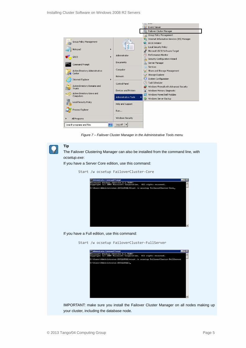
Figure 7 – Failover Cluster Manager in the Administrative Tools menu
Tip The Failover Clustering Manager can also be installed from the command line, with
ocsetup.exe:
If you have a Server Core edition, use this command:
Start /w ocsetup FailoverCluster-Core
If you have a Full edition, use this command:
Start /w ocsetup FailoverCluster-FullServer
IMPORTANT: make sure you install the Failover Cluster Manager on all nodes making up
your cluster, including the database node.
© 2013 Tango/04 Computing Group Page 5

Installing Cluster Software on Windows 2008 R2 Servers
2.2 Validate the Cluster NodesBefore configuring the cluster, it should be validated in order to see any errors or warnings the system
may have with regards to the Cluster you wish to configure.
To validate the cluster:
Step 1. Open the Failover Cluster Manager Administrative Tool, and click the Validate a
Configuration link in the Management section.
Figure 8 – Click the Validate a Configuration link in the Failover Cluster Manager Administrative Tool
Similarly, you can right-click the Failover Cluster Manager and select Validate a
Configuration from the context menu that appears.
Figure 9 – Right-click the Failover Cluster Manager and select Validate a Configuration
Step 2. In the Before You Begin window, click Next.
Figure 10 – The Validate a Configuration Wizard
Step 3. The Select Servers or a Cluster window appears. Select the servers with which you
wish to configure as a cluster. Click Next to continue.
© 2013 Tango/04 Computing Group Page 6

Installing Cluster Software on Windows 2008 R2 Servers
Figure 11 – Select the servers - remember to enter your database server as well (a cluster is normally composed of at least 3 machines)
Step 4. In the Testing Options window, select Run all tests (recommended). Windows will
perform the following types of tests:
• Cluster Configuration
• Inventory
• Network
• Storage
• System Configuration.
NOTE: If your machines are in service, you probably don’t want to test them at this time.
If for example there are shared disks present, with data, and in service it would be better
to test them during downtime. If you prefer you can select to run only a selection of tests
by selecting the second option.
Figure 12 – Testing options
© 2013 Tango/04 Computing Group Page 7

Installing Cluster Software on Windows 2008 R2 Servers
Step 5. In the Confirmation window, click Next to continue, the selected tests will begin.
Figure 13 – Click next to start the tests
Step 6. The Summary window appears with the results of the cluster validation. It is important
to know how to interpret them. In other words, like in our example, we don’t yet have
any shared storage system, so that is why we are seeing some storage-related
warnings, which we can disregard.
Figure 14 – Validation summary
Important Remember, all nodes (both database and processing servers) must be Validated.
© 2013 Tango/04 Computing Group Page 8

Creating the Cluster
Chapter 33 Creating the Cluster
Having passed the cluster validation test, you are ready to create your cluster.
To create a cluster:
Step 1. Open the Failover Cluster Manager. Right-click the Failover Cluster Manager and
select Create a Cluster.
Figure 15 – Click Create a Cluster
Step 2. The Create Cluster Wizard opens, showing the Before You Begin window.
Click Next.
Note
These steps only need to be performed from one node server.
© 2013 Tango/04 Computing Group Page 9

Creating the Cluster
Figure 16 – Create Cluster Wizard
Step 3. The Select Servers window opens. Select the servers that you wish to make up your
cluster.
Figure 17 – Select the servers that you wish to make up your cluster
Click Next to continue.
NOTE: If the validation window appears, you can click No, as you have already
validated your servers.
Step 4. The Access Point for Administering the Cluster window appears. Enter the name you
wish to assign to your cluster, and in the Networks box, enter the IP address that will
serve as the access point to your cluster.
NOTE: If your environment is configured to assign IPs directly from a DHCP server
then no Networks box will appear; entering a name for the cluster will suffice.
© 2013 Tango/04 Computing Group Page 10

Creating the Cluster
Figure 18 – Access Point for Administering the Cluster window
Step 5. The Confirmation window appears. Review your settings, and once satisfied, click
Next.
Figure 19 – Confirmation window
Step 6. The Cluster configuration begins.
© 2013 Tango/04 Computing Group Page 11

Creating the Cluster
Figure 20 – The Cluster configuration begins
Step 7. Once the Summary window appears, Cluster creation is complete. Review the
warnings, if any.
Figure 21 – In our case, there are two warnings that do not concern us, because we have not yet configured a shared disk or shared folder that can act as our quorum.
TIP: Click View Report to see a Microsoft Web-report about the cluster.
Click Finish. In the Failover Cluster Manager, the newly created Cluster appears.
Figure 22 – The newly created Cluster
© 2013 Tango/04 Computing Group Page 12

Creating the Cluster
Step 8. Rename your Cluster Networks, if desired.
Figure 23 – Rename your Cluster Networks
© 2013 Tango/04 Computing Group Page 13

Adding a Shared Disk to Use as a Quorum
Chapter 44 Adding a Shared Disk to Use as a Quorum
Now you are ready configure a quorum for the cluster. This involves creating a new shared disk. First,
though, we need to install Microsoft iSCSI Software Target.
4.1 Installing Microsoft Software on a Storage ServerTo install Microsoft iSCSI Software Target:
Step 1. Download the software from either of these places:
• http://www.microsoft.com/en-us/download/details.aspx?id=19867
• \\tango04\Software\Microsoft iSCSI Software Target\iscsiTargetqfe6.exe
Step 2. Run the Microsoft iSCSI Software Target installer.
Figure 24 – Windows installer
After a few seconds the following window appears:
Figure 25 – Microsoft iSCSI Software Target Setup Wizard
© 2013 Tango/04 Computing Group Page 14

Adding a Shared Disk to Use as a Quorum
Click Next.
Figure 26 – License Agreement
Step 3. Read and accept the License Agreement, and click Install.
Figure 27 – Installation completed
Click Finish to continue.
Once Microsoft iSCSI Software Target is installed, it becomes available on the Windows Start menu in
the Administrative Tools.
Figure 28 – Microsoft iSCSI Software Target is available on the Windows Start menu in the Administrative Tools.
© 2013 Tango/04 Computing Group Page 15

Adding a Shared Disk to Use as a Quorum
4.2 Configuring a Shared DiskOnce Microsoft iSCSI Software Target is installed the following configurations need to be performed to
get iSCSI SAN up and running:
• Installation of iSCSI Initiator on both of our cluster nodes. TIP: this tool is standard on Windows
2008 Servers.
Figure 29 – iSCSI Initiator in the Administrative Tools menu
• Configuration of the target iSCSIs, Virtual Disks and iSCSI clients (iSCSI initiators).
4.2.1 Configuring a Target iSCSI
To create a new iSCSI Target:
Step 1. Open Microsoft iSCSI Software Target from Administrative Tools.
Right-click iSCSI Targets and select Create iSCSI Target.
Figure 30 – Create iSCSI Target
The Create iSCSI Target Wizard starts, click Next.
© 2013 Tango/04 Computing Group Page 16

Adding a Shared Disk to Use as a Quorum
Figure 31 – Create iSCSI Target Wizard
Step 2. Enter a name and a description for the new Target. TIP: Name the Target as you would
a machine (in a single string).
Figure 32 – Enter a name and a description for the new Target
Click Next to continue. The Create iSCSI Target window appears.
Step 3. Specifying iSCSI Initiators for Target.
At this point, still in the storage server, the Create iSCSI Target window is open, asking
for the iQN identifier.
But before doing this, we must retrieve the initiator name of each server node that make
up the cluster:
• for each server (in our example, 2k8cluster1 and 2k8cluster2) click the Windows
Start menu and select Administrative Tools, and click iSCSI Initiator.
• In the iSCSI Initiator Properties window, click the Configuration tab. Notice the
Initiator Name field.
© 2013 Tango/04 Computing Group Page 17

Adding a Shared Disk to Use as a Quorum
Figure 33 – Initiator name field
• Record the initiator name of each server.
Step 4. Enter the Initiator Names.
Back in the storage server, in the Create iSCSI Target window, enter the initiator name
of the first Target client.
Figure 34 – Enter the initiator name of the first Target client
Click Next.
© 2013 Tango/04 Computing Group Page 18

Adding a Shared Disk to Use as a Quorum
Figure 35 – The Create iSCSI Target Wizard has completed
Click Finish.
4.2.2 Adding the Second Custer NodeInstead of repeating this process for your second cluster node, there is another way that you can add it
as a client for your Target.
To add the second cluster node as a client for your Target:
Step 1. In the iSCSI Target window, click iSCSI Targets.
Figure 36 – Click iSCSI Targets
Step 2. Right-click on the Target and select Properties from the context menu.
© 2013 Tango/04 Computing Group Page 19

Adding a Shared Disk to Use as a Quorum
Figure 37 – Open properties for the Target
Step 3. Click the iSCSI Initiator tab in the Target Properties window.
Figure 38 – iSCSI Initiator tab
Step 4. Click Add. This following window appears:
Figure 39 – Add / Edit Identifier
© 2013 Tango/04 Computing Group Page 20

Adding a Shared Disk to Use as a Quorum
Step 5. In the Identifier Type field, ensure that IQN is selected. In the value field, paste the
initiator name of your second cluster server, and click OK.
Figure 40 – Paste the initiator name of your second cluster server in the value field
Step 6. Click the Authentication tab and configure CHAP, if desired.
Figure 41 – Authentication tab
4.3 Create and Configure a Virtual Disk (LUN)
4.3.1 Creating a Virtual DiskOnce you have added your server nodes as initiators for the Target you can create a new Virtual Disk
(which will be used as your cluster quorum).
To create a virtual disk:
Step 1. Continuing in your database server, click the Windows Start menu, select
Administrative Tools, and click Microsoft iSCSI Software Target.
© 2013 Tango/04 Computing Group Page 21

Adding a Shared Disk to Use as a Quorum
Step 2. Click iSCSI Targets, right-click the Target and select Create Virtual Disk for iSCSI
Target from the context menu.
Figure 42 – Select Create Virtual Disk for iSCSI Target from the context menu
Step 3. The Create Virtual Disks wizard opens.
Figure 43 – Create Virtual Disks wizard
Click Next. Enter the full path of your Target in the File field, assigning .vhd as the
extension of the file.
© 2013 Tango/04 Computing Group Page 22

Adding a Shared Disk to Use as a Quorum
Figure 44 – Enter the full path of your Target in the File field
Click Next.
Step 4. Enter the desired size for the virtual disk in MB.
TIP: See the Tango/04 document Clustering VISUAL Message Center with Microsoft
Cluster Services for the recommended sizes for each product.
Figure 45 – Enter the desired size for the virtual disk in MB
Click Next to continue.
Step 5. Enter a description for the new virtual disk.
© 2013 Tango/04 Computing Group Page 23

Adding a Shared Disk to Use as a Quorum
Figure 46 – Enter a description for the new virtual disk
Click Next to continue.
Figure 47 – The wizard is completed
Click Finish.
To verify that the quorum has been created, open Windows Explorer and select the drive you assigned
the new disk to. The virtual disk should appear in the list (a VHD file) along with an identically named file
that ends with the extension .CBM.
© 2013 Tango/04 Computing Group Page 24
Adding a Shared Disk to Use as a Quorum
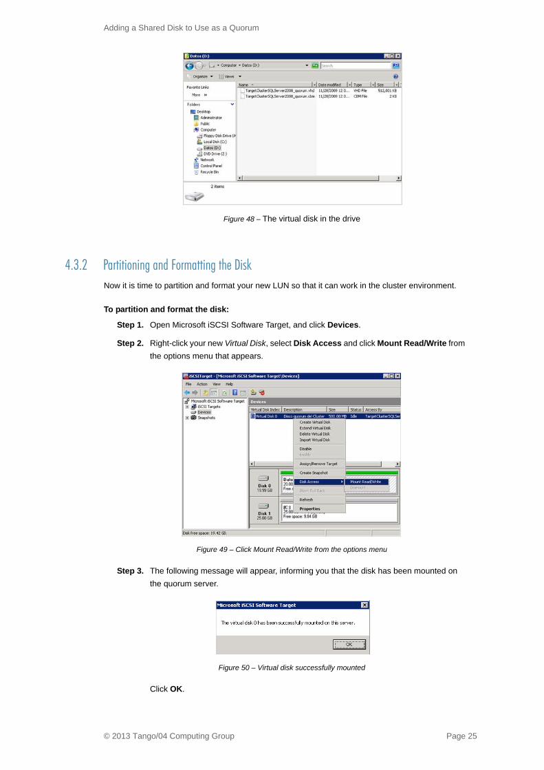
Figure 48 – The virtual disk in the drive
4.3.2 Partitioning and Formatting the DiskNow it is time to partition and format your new LUN so that it can work in the cluster environment.
To partition and format the disk:
Step 1. Open Microsoft iSCSI Software Target, and click Devices.
Step 2. Right-click your new Virtual Disk, select Disk Access and click Mount Read/Write from
the options menu that appears.
Figure 49 – Click Mount Read/Write from the options menu
Step 3. The following message will appear, informing you that the disk has been mounted on
the quorum server.
Figure 50 – Virtual disk successfully mounted
Click OK.
© 2013 Tango/04 Computing Group Page 25

Adding a Shared Disk to Use as a Quorum
Step 4. Open the Server Manager.
Click the down arrow next to Storage in the Server Manager tree to expand the list, and
select Disk Management. The Initialize Disk window opens.
Figure 51 – The Initialize Disk window
Step 5. Select the MBR (Master Boot Record) partition style, and click OK.
4.3.3 Creating a Volume on the Disk
To create a volume on the disk:
Step 1. In the Server Manager (still in your database server), right-click the new Virtual Disk and
select New Simple Volume from the options menu that appears.
Figure 52 – Right-click the new Virtual Disk and select New Simple Volume from the options menu
Step 2. The New Simple Volume Wizard opens.
© 2013 Tango/04 Computing Group Page 26

Adding a Shared Disk to Use as a Quorum
Figure 53 – The New Simple Volume Wizard
Click Next to continue.
Use the arrows to enter a volume size for the LUN in the Simple volume size in MB field.
Figure 54 – Enter a volume size for the LUN
Click Next.
Step 3. Select the Do not assign a drive letter or drive path option in the Assign Drive Letter
window.
© 2013 Tango/04 Computing Group Page 27

Adding a Shared Disk to Use as a Quorum
Figure 55 – Assign Drive Letter window
Click Next. The Format Partition window appears.
Step 4. Select the Format this volume… option, and select the following values for the
following drop-down list boxes:
• File System: select NTFS
• Allocation unit size: Default
• Volume label: you can leave the default name
Figure 56 – Format Partition window
Click Next.
© 2013 Tango/04 Computing Group Page 28

Adding a Shared Disk to Use as a Quorum
Figure 57 – Wizard completed
Click Finish.
Step 5. The system begins to create and format the partition/volume.
Figure 58 – Formatting and partioning of the drive started
Finally, the disk can be used.
Figure 59 – Disk ready to use
Step 6. Now you can dismount the disk so it can be available virtually.
© 2013 Tango/04 Computing Group Page 29

Adding a Shared Disk to Use as a Quorum
In the Microsoft iSCSI Software Target, right-click the Virtual Disk, select Disk Access,
and click Dismount.
Figure 60 – Dismount the disk
A confirmation dialog appears.
Figure 61 – Confirmation dialog
Step 7. Click Yes to proceed. Finally, a dialog indicating that the new Virtual Disk has been
removed successfully appears. Click OK.
Figure 62 – Virtual Disk has been removed successfully
The new Virtual Disk (LUN) is now partitioned and formatted.
© 2013 Tango/04 Computing Group Page 30

Configuring iSCSI Initiators to Work with the Virtual Disk
Chapter 5 5 Configuring iSCSI Initiators to Work with the Virtual Disk
5.1 Adding a Target to Each InitiatorTo add a Target to an Initiator:
Step 1. In each cluster node server, open the iSCSI Initiator from Administrative Tools.
Figure 63 – open the iSCSI Initiator from Administrative Tools
If you see this message click Yes to continue:
Figure 64 – iSCSI service is not running
© 2013 Tango/04 Computing Group Page 31

Configuring iSCSI Initiators to Work with the Virtual Disk
Figure 65 – The service is manually started by default
Step 2. The iSCSI Initiator Properties window opens.
Click the Discovery tab, then click the Discover Portal button. This will enable you to
add the database server as a target for the initiator.
Figure 66 – Discovery tab
Step 3. Enter the IP address of the server you wish to act as the cluster quorum.
Figure 67 – Enter the IP address of the server
Click OK.
© 2013 Tango/04 Computing Group Page 32
Configuring iSCSI Initiators to Work with the Virtual Disk
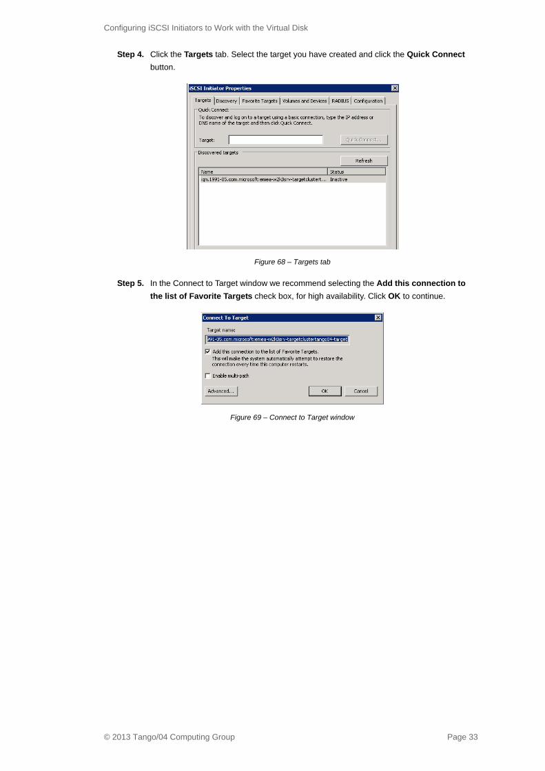
Step 4. Click the Targets tab. Select the target you have created and click the Quick Connect
button.
Figure 68 – Targets tab
Step 5. In the Connect to Target window we recommend selecting the Add this connection to
the list of Favorite Targets check box, for high availability. Click OK to continue.
Figure 69 – Connect to Target window
© 2013 Tango/04 Computing Group Page 33
Configuring iSCSI Initiators to Work with the Virtual Disk
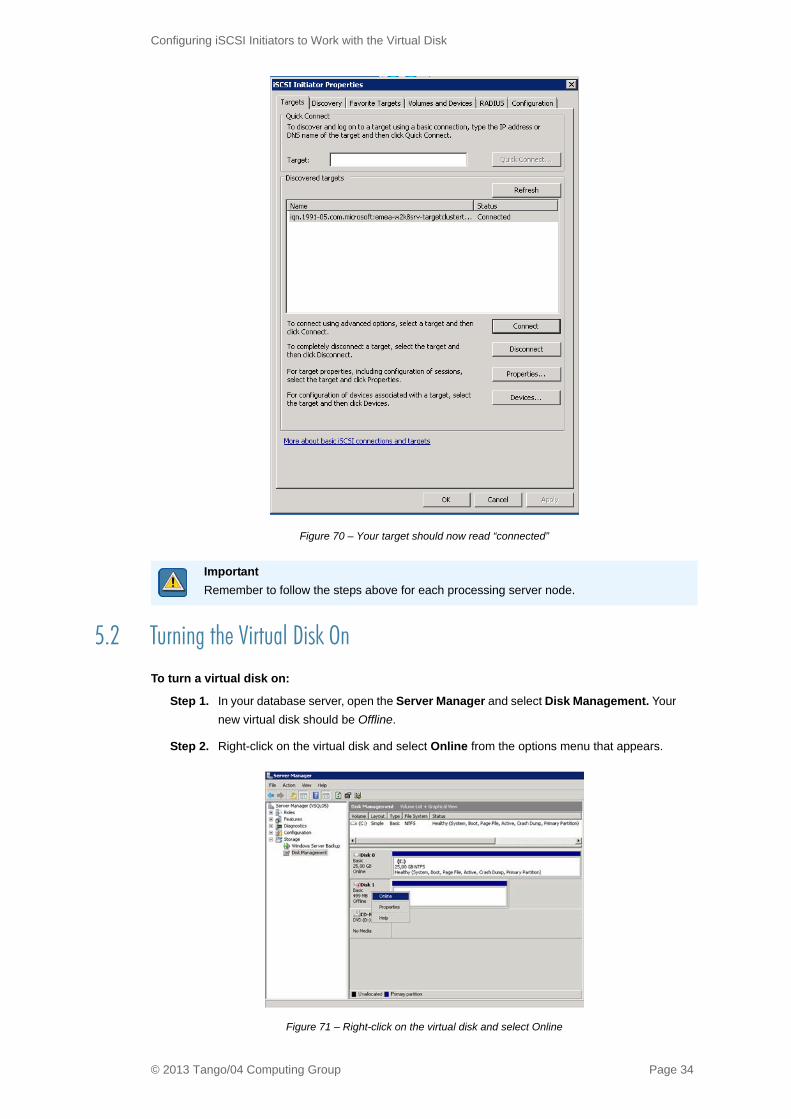
Figure 70 – Your target should now read “connected”
5.2 Turning the Virtual Disk OnTo turn a virtual disk on:
Step 1. In your database server, open the Server Manager and select Disk Management. Your
new virtual disk should be Offline.
Step 2. Right-click on the virtual disk and select Online from the options menu that appears.
Figure 71 – Right-click on the virtual disk and select Online
Important Remember to follow the steps above for each processing server node.
© 2013 Tango/04 Computing Group Page 34

Configuring iSCSI Initiators to Work with the Virtual Disk
Having done this, client servers can now reach our virtual disk.
Figure 72 – Client servers can now reach our virtual disk
5.3 Adding the Virtual Disk to the ClusterTo add the virtual disk to the cluster:
Step 1. Still in the database server, open the Failover Cluster Manager from Administrative
Tools. Expand the cluster and right-click on Storage, then select Add a disk.
Figure 73 – Add a disk
Step 2. In the Add Disks to a Cluster window select the checkbox next to your new virtual disk.
Figure 74 – Select the checkbox next to your new virtual disk
© 2013 Tango/04 Computing Group Page 35

Configuring iSCSI Initiators to Work with the Virtual Disk
Click OK. You have now added the shared disk for quorum to this database server node
of your cluster.
Figure 75 – Virtual disk added to cluster
© 2013 Tango/04 Computing Group Page 36

Configuring the Quorum
Chapter 6 6 Configuring the Quorum
Now you have to configure the quorum for your database server.
To configure the quorum:
Step 1. Open the Administrative Tool Failover Cluster Manager (in the database server),
right-click on the cluster and select More Actions, then click Configure Cluster
Quorum Settings.
Figure 76 – Click Configure Cluster Quorum Settings
The Configure Cluster Quorum Wizard opens.
Figure 77 – Configure Cluster Quorum Wizard
Click Next to continue.
Step 2. In the Select Quorum Configuration window select the Node and Disk Majority option.
© 2013 Tango/04 Computing Group Page 37

Configuring the Quorum
Figure 78 – Select the Node and Disk Majority option
Click Next.
Step 3. In the Configure Storage Witness window select the virtual disk that will serve as your
quorum.
Figure 79 – Select the virtual disk that will serve as your quorum
Click Next.
Step 4. The Confirmation window opens, click Next.
Figure 80 – Confirmation window
Step 5. The Summary window opens, click Finish.
© 2013 Tango/04 Computing Group Page 38

Configuring the Quorum
Figure 81 – Summary window
© 2013 Tango/04 Computing Group Page 39

Install VISUAL Message Center
© 2013 Tango/04 Computing Group Page 40
Chapter 7 7 Install VISUAL Message Center
Once the cluster has been created and configured, install all of your Tango/04 software on each cluster
server node (not necessary in storage node). This is done node by node.
Please read the VISUAL Message Center Installation Overview before installing the products, as
important prerequisites for the software are listed. There are also installation guides available for each
particular VISUAL Message Center program. You can find them on the Tango/04 Customer Portal.
7.1 Installing on the First NodeWhen you install on one cluster node, you should stop the other cluster node.
To do so, open the Failover Cluster Manager (from any node) and stop the cluster service of the nodes
that are clustered with the node you are going to install on.
Figure 82 – Stop the cluster service of the nodes that are clustered with the node you are going to install on
Once VISUAL Message Center is installed on the first node, stop the node, and install VISUAL Message
Center on the second node.
7.2 Installing on the Second NodeOpen the Failover Cluster Manager in your remaining node and stop the cluster service of the node that
you have already installed VISUAL Message Center on.
Important DSN configuration, and SecAdmn user and password need to be the same on each node
(before and during installation).

Create Generic Failover Cluster Manager Services
Chapter 8 8 Create Generic Failover Cluster Manager Services
To create generic Failover Cluster Manager Services:
Step 1. For each cluster server node, open the Failover Cluster Manager from Administrative
Tools. Expand your cluster and right-click Services and applications, then select
Configure a Service or Application from the options menu that appears.
Figure 83 – Select Configure a Service or Application from the options menu
Step 2. In the window that appears, select Generic Service.
Figure 84 – High Availability Wizard
Click Next.
© 2013 Tango/04 Computing Group Page 41

Create Generic Failover Cluster Manager Services
Figure 85 – Select Service window
Step 3. In the Select Service window select the first VISUAL Message Center service listed.
Then click Next.
Figure 86 – Client Access Point window
Step 4. In the Client Access Point window enter a name for the VISUAL Message Center
service in the name field. This name will be available to others on your network.
Click Next. The Select Storage window opens.
© 2013 Tango/04 Computing Group Page 42

Create Generic Failover Cluster Manager Services
Figure 87 – Select Storage window
Step 5. Select the virtual disk you created for the quorum and click Next.
Step 6. The Replicate Registry Settings window opens. In case you have registry dependencies
on the system, you can indicate, here, which registry fields to replicate when a cluster
node becomes unavailable and VISUAL Message Center has to run completely on
another node.
Figure 88 – Replicate Registry Settings window
Click Next.
Step 7. The Confirmation window opens. Click Next.
© 2013 Tango/04 Computing Group Page 43

Create Generic Failover Cluster Manager Services
Figure 89 – Confirmation window
Step 8. The Summary window opens. Click Finish.
Figure 90 – Summary window
© 2013 Tango/04 Computing Group Page 44

Create Generic Failover Cluster Manager Services
Important Please follow these steps for each VISUAL Message Center service that appears in your
Windows Services window. In the end, you will want to have each service named as a
generic service in the Failover Cluster Manager.
Figure 91 – Each service should be named as a generic service in the Failover Cluster Manager
Important Assign the exact same names to the VISUAL Message Center services in the Failover
Cluster Manager on your other node. Remember to create generic Failover Cluster Manager
services for each VISUAL Message Center service.
Tip You can add another service to an existing Failover Cluster Manager service, and in that
way, group them logically, if desired. For example, one service for ThinkServer, another for
SmartConosle, and a group of services for Tango/04 Web apps.
Figure 92 – Add a generic Service resource
© 2013 Tango/04 Computing Group Page 45

Create Generic Failover Cluster Manager Services
Warning When clustering VISUAL Message Center, do not assign any startup parameters to
ThinkServer and AccessServer. This will cause an error with their services.
Figure 93 – It is important to have no Startup parameters assigned to these Services
Figure 94 – You can view start parameters in a service’s Properties window
© 2013 Tango/04 Computing Group Page 46

Appendix A : Contacting Tango/04
Appendix AAppendix A: Contacting Tango/04
North America
Tango/04 North America
PO BOX 3301
NH 03458 Peterborough USA
Phone: 1-800-304-6872 / 603-924-7391
Fax: 858-428-2864
www.tango04.com
EMEA
Tango/04 Computing Group S.L.
Avda. Meridiana 358, 5 A-B
08027 Barcelona Spain
Phone: +34 93 274 0051
Fax: +34 93 345 1329
www.tango04.com
Italy
Tango/04 Italy
Viale Garibaldi 51/53
13100 Vercelli Italy
Phone: +39 0161 56922
Fax: +39 0161 259277
www.tango04.it
Sales Office in France
Tango/04 France
La Grande Arche
Paroi Nord 15ème étage
92044 Paris La Défense France
Phone: +33 01 40 90 34 49
Fax: +33 01 40 90 31 01
www.tango04.fr
Sales Office in Switzerland
Tango/04 Switzerland
18, Avenue Louis Casaï
CH-1209 Genève
Switzerland
Phone: +41 (0)22 747 7866
Fax: +41 (0)22 747 7999
www.tango04.fr
Latin American Headquarters
Barcelona/04 Computing Group SRL (Argentina)
Avda. Federico Lacroze 2252, Piso 6
1426 Buenos Aires Capital Federal
Argentina
Phone: +54 11 4774-0112
Fax: +54 11 4773-9163
www.barcelona04.com
© 2013 Tango/04 Computing Group Page 47

Sales Office in Peru
Barcelona/04 PERÚ
Centro Empresarial Real
Av. Víctor A. Belaúnde 147, Vía Principal 140 Edificio Real Seis, Piso 6
L 27 Lima
Perú
Phone: +51 1 211-2690
Fax: +51 1 211-2526
www.barcelona04.com
Sales Office in Chile
Barcelona/04 Chile
Nueva de Lyon 096 Oficina 702,
Providencia
Santiago
Chile
Phone: +56 2 234-0898
Fax: +56 2 2340865
www.barcelona04.com
© 2013 Tango/04 Computing Group Page 48

About Tango/04 Computing Group
Tango/04 Computing Group is one of the leading developers of systems management and automation
software. Tango/04 software helps companies maintain the operating health of all their business
processes, improve service levels, increase productivity, and reduce costs through intelligent
management of their IT infrastructure.
Founded in 1991 in Barcelona, Spain, Tango/04 is an IBM Business Partner and a key member of IBM's
Autonomic Computing initiative. Tango/04 has more than a thousand customers who are served by over
35 authorized Business Partners around the world.
Alliances
Awards
Partnerships IBM Business Partner
IBM Autonomic Computing Business Partner
IBM PartnerWorld for Developers Advanced Membership
IBM ISV Advantage Agreement
IBM Early code release
IBM Direct Technical Liaison
Microsoft Developer Network
Microsoft Early Code Release
© 2013 Tango/04 Computing Group Page 49

Legal Notice
The information in this document was created using certain specific equipment and environments, and it is limited in
application to those specific hardware and software products and version and releases levels.
Any references in this document regarding Tango/04 Computing Group products, software or services do not mean
that Tango/04 Computing Group intends to make these available in all countries in which Tango/04 Computing Group
operates. Any reference to a Tango/04 Computing Group product, software, or service may be used. Any functionally
equivalent product that does not infringe any of Tango/04 Computing Group's intellectual property rights may be used
instead of the Tango/04 Computing Group product, software or service
Tango/04 Computing Group may have patents or pending patent applications covering subject matter in this
document. The furnishing of this document does not give you any license to these patents.
The information contained in this document has not been submitted to any formal Tango/04 Computing Group test
and is distributed AS IS. The use of this information or the implementation of any of these techniques is a customer
responsibility, and depends on the customer's ability to evaluate and integrate them into the customer's operational
environment. Despite the fact that Tango/04 Computing Group could have reviewed each item for accurateness in a
specific situation, there is no guarantee that the same or similar results will be obtained somewhere else. Customers
attempting to adapt these techniques to their own environments do so at their own risk. Tango/04 Computing Group
shall not be liable for any damages arising out of your use of the techniques depicted on this document, even if they
have been advised of the possibility of such damages. This document could contain technical inaccuracies or
typographical errors.
Any pointers in this publication to external web sites are provided for your convenience only and do not, in any
manner, serve as an endorsement of these web sites.
The following terms are trademarks of the International Business Machines Corporation in the United States and/or
other countries: iSeries, iSeriese, iSeries, i5, DB2, e (logo)®Server IBM ®, Operating System/400, OS/400, i5/OS.
Microsoft, SQL Server, Windows, Windows NT, Windows XP and the Windows logo are trademarks of Microsoft
Corporation in the United States and/or other countries. Java and all Java-based trademarks and logos are
trademarks or registered trademarks of Sun Microsystems, Inc. in the United States and/or other countries. UNIX is a
registered trademark in the United States and other countries licensed exclusively through The Open Group. Oracle
is a registered trade mark of Oracle Corporation.
Other company, product, and service names may be trademarks or service marks of other companies.
© 2013 Tango/04 Computing Group Page 50