cma cable component catalog
DESCRIPTION
Are you in need of some new products such as electrical cables, push pull cables, control cables, cycle flex miniature parts, or other materials for your next project? Whatever you need you'll be sure to find it through CMA Cable. Check out their product catalog for a full listing of all available products. Visit http://www.cmacable.com for more information.TRANSCRIPT

Component Catalog
10896 Industrial parkway nW | po Box 409 | Bol ivar, oH 44612-0409 | 800.586.8404 | www.cmacable.com
Cable ManufaCturing & asseMbly Co. inC.
Table of Contents
I. Cable Specifications 1
I I. PlastiCable Specifications 2 – 3
I I I. Cable End Fittings 4 – 16
IV. Solid Core Wire/Terminations 17 – 18
V. Cycle-Flex Cable Specifications 19
VI. Cycle-Flex Cable End Fittings 20 – 27
VII. Conduit Specifications 28
VIII. Remote Actuation Systems 29 – 37
IX. Conduit End Fittings 38 – 42
Cable ManufaCturing & asseMbly Co. inC.

www.cmacable.com 1.800.586.8404
COMMERCIAL CABLE SPECIFICATIONS
1 x 7
Galvanized Stainless Steel WeightDiameter Tolerance Min. Breaking EA Min. Breaking EA per M
(+) CMA Strength Value CMA Strength Value Ft.in. /mm in. /mm Part No.* Lb./ Kg. x103 Part No.* Lb./ Kg. x103 Lb./ Kg.
1/32/ 0.8 .005/0.13 Available in Stainless Steel Only — S031C 125/ 57 13 2/ 0.9
3/64/1.2 .005/ 0.13 G047C 375/ 170 30 S047C 375/ 170 29 5.2/ 2.4
1/16/1.6 .006/ 0.15 G063C 500/ 227 55 S063C 500/ 227 52 8.5/ 3.9
5/64/2.0 .008/ 0.20 G078C 800/ 363 84 S078C 800/ 363 80 14/ 6.3
3/32/2.4 .009/ 0.23 G094C 1,200/ 544 121 S094C 1,200/ 544 116 21/ 9.5
1/8/3.2 .013/ 0.33 G125C 1,830/ 830 215 S125C 1,830/ 830 205 32/ 15
5/32/4.0 .016/ 0.41 G156C 2,940/1,333 215 S156C 2,940/1,333 320 50/ 23
3/16/4.8 .013/ 0.33 G188C 3,990/1,810 215 S188C 3,990/1,810 464 72/ 33
7/32/5.6 .015/ 0.38 G219C 5,400/2,449 659 S219C 5,400/2,449 630 98/ 44
1/4/6.4 .018/ 0.46 G250C 6,650/3,016 859 S250C 6,650/3,016 821 120/ 54
1/32/0.8 .003/ 0.08 G031E 175/ 79 13 S031E 150/ 68 12 2/ 0.9
3/64/1.2 .003/ 0.08 G045E 350/ 159 18 S045E 300/ 136 21 4.3/1.95
3/64/1.2 .005/ 0.13 G047E 375/ 170 29 S047E 335/ 152 28 5.2/ 2.4
1/16/1.6 .006/ 0.15 G063E 500/ 227 52 S063E 500/ 227 50 8.5/ 3.9
5/64/2.0 .008/ 0.20 G078E 800/ 363 80 S078E 800/ 363 76 14.2/ 6.5
3/32/2.4 .009/ 0.23 G094E 1,200/ 544 116 S094E 1,200/ 544 111 20/ 9
1/8/3.2 .013/ 0.33 G125E 2,100/ 952 205 S125E 2,100/ 952 196 35/ 16
5/32/4.0 .016/ 0.41 G156E 3,300/1,497 320 S156E 3,300/1,497 305 57/ 26
3/16/4.8 .013/ 0.33 G188E 4,700/2,132 464 S188E 4,700/2,132 443 78/ 35
7/32/5.6 .015/ 0.38 G219E 6,300/2,857 630 S219E 6,300/2,857 601 101/ 46
1/4/6.4 .018/ 0.46 G250E 8,200/3,719 821 S250E 8,200/3,719 783 135/ 61
9/32/7.1 .020/ 0.51 G281E 9,900/4,490 1037 S281E 9,900/4,490 990 172/ 78
5/16/7.9 .023/ 0.58 G313E 12,500/5,669 1287 S313E 12,500/5,669 1228 210/ 95
3/8/9.5 .026/ 0.66 G375E 18,000/8,163 1847 S375E 18,000/8,163 1763 305/ 138
1/32/0.8 .005/ 0.13 Available in Stainless Steel Only — S031N 115/ 52 9 1.5/ 0.6
1/32/0.8 .005/ 0.13 Available in Stainless Steel Only — S036N 150/ 56 11 1.5/ 0.6
3/64/1.2 .006/ 0.15 G047N 270/ 122 22 S047N 270/ 122 20 4.1/ 1.9
1/16/1.6 .010/ 0.25 G063N 480/ 218 40 S063N 480/ 5218 36 7.5/ 3.4
5/64/2.0 .010/ 0.25 G078N 650/ 295 61 S078N 650/ 295 55 12/ 5.5
3/32/2.4 .012/ 0.30 G094N 920/ 417 88 S094N 920/ 417 80 16/ 7
1/8/3.2 .014/ 0.36 G125N 1,700/ 771 156 S125N 1,700/ 771 141 29/ 13
5/32/4.0 .016/ 0.41 G156N 2,600/1,179 243 S156N 2,400/1,088 220 45/ 20
3/16/4.8 .018/ 0.46 G188N 3,700/1,678 353 S188N 3,700/1,678 319 61/ 28
7/32/5.6 .018/ 0.46 G219N 4,800/2,177 479 S219N 4,800/2,177 433 82/ 37
1/4/ 6.4 .018/ 0.46 G250N 6,100/2,766 624 S250N 6,100/2,766 564 107/ 49
9/32/7.1 .020/ 0.51 G281N 7,400/3,356 788 S281N 7,400/3,356 713 135/ 61
5/16/7.9 .022/ 0.56 G313N 9,200/4,172 977 S313N 9,100/4,127 884 166/ 75
3/8/9.5 .026/ 0.66 G375N 13,300/6,032 1403 S375N 12,600/5,714 1269 238/ 108
1/16/1.6 .010/ 0.25 G063T 480/ 218 35 S063T 480/ 218 31 8.1/ 3.7
3/32/2.4 .012/ 0.30 G094T 1,000/ 454 78 S094T 920/ 417 70 16/ 7.3
1/8/3.2 .014/ 0.36 G125T 2,000/ 907 138 S125T 1,760/ 798 123 30/13.6
5/32/4.0 .016/ 0.41 G156T 2,800/1,270 215 S156T 2,400/1,088 192 44/ 20
3/16/4.8 .018/ 0.46 G188T 4,200/3,485 312 S188T 3,700/1,678 279 63/ 29
7/32/5.6 .018/ 0.46 G219T 5,600/2,540 423 S219T 5,000/2,268 379 85/ 39
1/4/6.4 .018/ 0.46 G250T 7,000/3,175 551 S250T 6,100/2,766 493 108/ 49
9/32/7.1 .020/ 0.51 G281T 8,000/3,628 697 S281T 7,800/3,537 623 140/ 263
5/16/7.9 .022/ 0.56 G313T 9,800/4,444 864 S313T 9,000/4,082 773 175/ 79
3/8/9.5 .026/ 0.66 G375T 14,400/6,531 1240 S375T 12,000/5,443 1110 245/ 111
7 x 7
1 x 19
7 x 19
C A B L E M A N U F A C T U R I N G A N D A S S E M B L Y C O . I N C .
C
E
N
T
NOTE: CMA cable part numbers contain a prefix which designates the cable material as well as a Suffix which designates the cable construction. Prefix: G-Galvanized or S-Stainless Steel Suffix: C-1x7, E-1x9, N-7x7, T-7x19 Suffix: D-Dry or A-Lubricated All cable is supplied dry (D) unless otherwise specified.
www.cmacable.com/specs/cma86
C A B L E M A N U F A C T U R I N G A N D A S S E M B L Y C O . I N C . 1
www.cmacable.com 1.800.586.8404
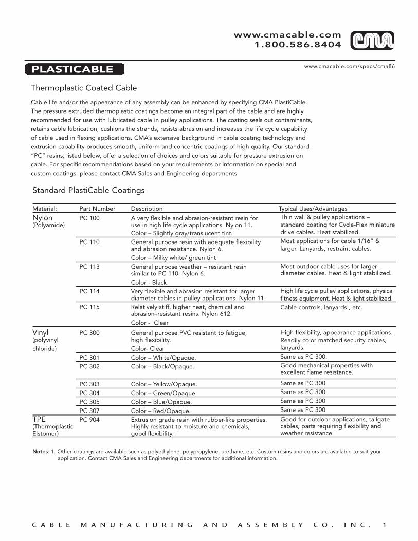
PLASTICABLE
Thermoplastic Coated Cable
Cable life and/or the appearance of any assembly can be enhanced by specifying CMA PlastiCable.The pressure extruded thermoplastic coatings become an integral part of the cable and are highlyrecommended for use with lubricated cable in pulley applications. The coating seals out contaminants,retains cable lubrication, cushions the strands, resists abrasion and increases the life cycle capabilityof cable used in flexing applications. CMA’s extensive background in cable coating technology andextrusion capability produces smooth, uniform and concentric coatings of high quality. Our standard“PC” resins, listed below, offer a selection of choices and colors suitable for pressure extrusion oncable. For specific recommendations based on your requirements or information on special and custom coatings, please contact CMA Sales and Engineering departments.
Thin wall & pulley applications – standard coating for Cycle-Flex miniaturedrive cables. Heat stabilized.Most applications for cable 1/16” & larger. Lanyards, restraint cables.
Most outdoor cable uses for larger diameter cables. Heat & light stabilized.
High life cycle pulley applications, physical fitness equipment. Heat & light stabilized.Cable controls, lanyards , etc.
High flexibility, appearance applications.Readily color matched security cables,lanyards.Same as PC 300.Good mechanical properties with excellent flame resistance.
Same as PC 300Same as PC 300Same as PC 300Same as PC 300
Good for outdoor applications, tailgatecables, parts requiring flexibility andweather resistance.
Standard PlastiCable Coatings
Material: Part Number Description Typical Uses/Advantages
Nylon PC 100 A very flexible and abrasion-resistant resin for (Polyamide) use in high life cycle applications. Nylon 11.
Color – Slightly gray/translucent tint.PC 110 General purpose resin with adequate flexibility
and abrasion resistance. Nylon 6.Color – Milky white/ green tint
PC 113 General purpose weather – resistant resin similar to PC 110. Nylon 6.Color - Black
PC 114 Very flexible and abrasion resistant for larger diameter cables in pulley applications. Nylon 11.
PC 115 Relatively stiff, higher heat, chemical and abrasion–resistant resins. Nylon 612.Color - Clear
Vinyl PC 300 General purpose PVC resistant to fatigue, (polyvinyl high flexibility.chloride) Color- Clear
PC 301 Color – White/Opaque.PC 302 Color – Black/Opaque.
PC 303 Color – Yellow/Opaque.PC 304 Color – Green/Opaque.PC 305 Color – Blue/Opaque.PC 307 Color – Red/Opaque.
TPE PC 904 Extrusion grade resin with rubber-like properties.(Thermoplastic Highly resistant to moisture and chemicals, Elstomer) good flexibility.
Notes: 1. Other coatings are available such as polyethylene, polypropylene, urethane, etc. Custom resins and colors are available to suit your application. Contact CMA Sales and Engineering departments for additional information.
www.cmacable.com/specs/cma86
C A B L E M A N U F A C T U R I N G A N D A S S E M B L Y C O . I N C . 2
www.cmacable.com 1.800.586.8404
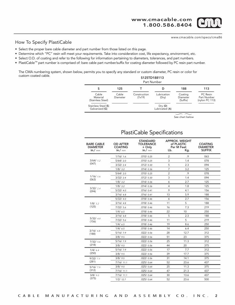
How To Specify PlastiCable• Select the proper bare cable diameter and part number from those listed on this page.• Determine which “PC” resin will meet your requirements. Take into consideration cost, life expectancy, environment, etc.• Select O.D. of coating and refer to the following for information pertaining to diameters, tolerances, and part numbers.• PlastiCable™ part number is comprised of: bare cable part number/suffix for coating diameter followed by PC resin part number.
The CMA numbering system, shown below, permits you to specify any standard or custom diameter, PC resin or color for custom coated cable.
S 125 T D 188 113
Cable Cable Construction Lubrication Coating PC ResinMaterial Diameter (7x19) (Dry) Diameter Part Number
(Stainless Steel) (Suffix) (nylon PC 113)
Stainless Steel (S) Dry (D)Galvanized (G) Lubricated (A)
S125TD188113Part Number
1/16/ 1.6 .010/ 0.25 2 .9 063
5/64/ 2.0 .010/ 0.25 3 1.4 078
3/32/ 2.4 .012/ 0.30 5 2.3 094
1/8/ 3.2 .014/ 0.36 7 3.2 125
5/64/ 2.0 .010/ 0.25 2 .9 078
3/32/ 2.4 .012/ 0.30 3 1.4 094
1/8/ 3.2 .014/ 0.36 6 2.7 125
1/8/ 3.2 .014/ 0.36 4 1.8 125
5/32/ 4.0 .016/ 0.41 9 4.1 156
3/16/ 4.8 .016/ 0.41 13 5.9 188
5/32/ 4.0 .018/ 0.46 6 2.7 156
3/16/ 4.8 .018/ 0.46 11 5 188
7/32/ 5.6 .018/ 0.46 16 7.3 219
1/4/ 6.5 .018/ 0.46 22 10 250
3/16/ 4.8 .018/ 0.46 5 2.3 188
7/32/ 5.6 .018/ 0.46 11 5 219
1/4/ 6.5 .018/ 0.46 19 8.6 250
1/4/ 6.5 .018/ 0.46 14 6.4 250
5/16/ 7.9 .022/ 0.56 28 12.7 312
3/8/ 9.5 .022/ 0.56 51 23 375
5/16/ 7.9 .022/ 0.56 25 11.3 312
3/8/ 9.5 .022/ 0.56 44 20 375
5/16/ 7.9 .022/ 0.56 17 7.7 312
3/8/ 9.5 .022/ 0.56 39 17.7 375
3/8/ 9.5 .022/ 0.56 31 14.1 375
7/16/ 11.1 .025/ 0.64 52 23.6 437
3/8/ 9.5 .025/ 0.64 25 11.3 375
7/16/ 11.1 .025/ 0.64 47 21.3 437
7/16/ 11.1 .025/ 0.64 30 13.6 437
1/2/ 12.7 .025/ 0.64 52 23.6 500
PlastiCable Specifications
See chart below
STANDARD APPROX. WEIGHTBARE CABLE OD AFTER TOLERANCE of PLASTIC COATINGDIAMETER COATING + Only Per M Feet DIAMETER
in./ mm in./ mm in./ mm Lb. Kg. SUFFIX
3/64/ 1.2(047)
1/16/ 1.6(063)
3/32/ 2.4(094)
1/8/ 3.2(125)
5/32/ 4.0(156)
3/16/ 4.8(188)
7/32/ 5.6(218)
1/4/ 6.4(250)
9/32/ 7.1(281)
5/16/ 7.9(312)
3/8/ 9.5(375)

C A B L E M A N U F A C T U R I N G A N D A S S E M B L Y C O . I N C .
www.cmacable.com 1.800.586.8404
CMA 10 SERIES EYE
A C
ID
OD
L
➤
➤
➤
➤
➤
➤
➤
➤
➤
➤
➤
➤
➤ ➤
H T
➤
➤
10/531 1/32/ 0.79 .142/ 3.61 .260/ 6.60 .042/ 1.07 .09 .17 .10 .63
10-581 1/32/ 0.79 .157/ 3.99 .260/ 6.60 .042/ 1.07 .09 .14 .09 .44
10-538 3/64/ 1.19 .125/ 3.18 .320/ 8.13 .046/ 1.17 .14 .19 .11 .73
10-047 3/64/ 1.19 .156/ 3.96 .320/ 8.13 .046/ 1.17 .14 .19 .11 .73
10-710 3/64/ 1.19 .165/ 4.19 .320/ 8.13 .046/ 1.17 .14 .19 .11 .73
10-653* 3/64/ 1.19 .165/ 4.19 .314/ 7.98 .048/ 1.22 .14 .23 .13 .71
10-556 3/64/ 1.19 .190/ 6.48 .320/ 8.13 .046/ 1.17 .14 .19 .11 .73
10-669 3/64/ 1.19 .167/ 4.24 .320/ 8.13 .046/ 1.17 .14 .19 .11 .73
10-063 1/16/ 1.59 .190/ 4.83 .420/ 10.67 .062/ 1.57 .29 .24 .16 .99
10-633 1/16/ 1.59 .220/ 5.59 .420/ 10.67 .062/ 1.57 .43 .26 .16 .96
10-634 1/16/ 1.59 .193/ 4.90 .320/ 8.13 .046/ 1.17 .33 .19 .11 .70
10-544 1/16/ 1.59 .235/ 5.97 .460/ 11.68 .062/ 1.57 .17 .26 .16 .82
10-553 1/16/ 1.59 .250/ 6.35 .460/ 11.68 .062/ 1.57 .17 .26 .16 .82
10-708 1/16/ 1.59 .261/ 6.63 .433/ 11.00 .036/ 0.91 .34 .19 .11 .89
10-532 1/16/ 1.59 .262/ 6.65 .460/ 11.68 .062/ 1.57 .17 .26 .16 .52
10-548 1/16/ 1.59 .262/ 6.65 .460/ 11.68 .062/ 1.57 .17 .26 .16 .82
10-589 1/16/ 1.59 .255/ 6.48 .420/ 10.67 .062/ 1.57 .29 .24 .16 .99
10-772 1/16/ 1.59 .165/ 4.19 .420/ 10.67 .060/ 1.52 .29 .24 .16 .99
10-709 5/64/ 1.98 .241/ 6.12 .394/ 10.01 .036/ 0.91 .34 .20 .14 .89
10-094 3/32/ 2.38 .255/ 6.48 .500/ 12.70 .093/ 2.36 .41 .34 .26 1.49
10-576 3/32/ 2.38 .312/ 7.92 .500/ 12.70 .093/ 2.36 .41 .34 .26 1.49
10-125 1/8/ 3.18 .255/ 6.48 .674/ 17.12 .125/ 3.18 .62 .44 .33 1.90
10-584 1/8/ 3.18 .281/ 7.14 .674/ 17.12 .125/ 3.18 .62 .44 .33 1.90
10-585 1/8/ 3.18 .343/ 8.71 .674/ 17.12 .125/ 3.18 .62 .44 .33 1.90
10-698** 1/8/ 3.18 .343/ 8.71 .874/ 22.20 .120/ 3.05 .64 .44 .33 1.90
10-668 1/8/ 3.18 .375/ 9.53 .674/ 17.12 .125/ 3.18 .62 .44 .33 1.90
10-667 5/32/ 3.97 .343/ 8.71 .745/ 18.92 .132/ 3.35 .47 .50 .36 1.77
10-630 5/32/ 3.97 .374/ 9.50 .745/ 18.92 .132/ 3.35 .47 .50 .36 1.77
10-628 5/32/ 3.97 .558/ 14.17 1.07/ 27.18 .162/ 4.11 .67 .53 .42 1.76
10-663 3/16/ 4.75 .558/ 14.17 1.07/ 27.18 .162/ 4.11 .67 .59 .45 2.10
10-705** 3/16/ 4.75 .348/ 8.83 1.00/ 25.40 .162/ 4.11 1.05 .56 .45 2.42
10-706 3/16/ 4.75 .591/ 15.00 1.07/ 27.18 .162/ 4.11 .19 .56 .45 2.
NOTE: Dimensions shown are “after swage” of fittings applied to cable.
PART NO. CABLE DIA. ID OD T C A H L±.010/ 0.25 ±.020/ 0.51 +.010/ 0.25 MIN. REF. REF. REF.-.005/ 0.13 -.005/ 0.13
in./ mm in./ mm in./ mm in./ mm

C A B L E M A N U F A C T U R I N G A N D A S S E M B L Y C O . I N C .
www.cmacable.com 1.800.586.8404
CMA 20 SERIES THREADED TERMINAL
H
L
THREAD
MEASURING POINT FOR ASSEMBLY
B MINFULL THD'S.
➤
➤
➤
➤
➤
➤
➤
➤
20-036 3/64/ 1.19 .105/ 2.6 1.00 .48 5-40
20-659 1/32/ 0.79 .132/ 3.35 1.50 .94 8-32
20-716 3/64/ 1.19 .135/ 3.43 1.57 1.07 M4x0.7
20-047 3/64/ 1.19 .162/ 4.10 1.00 .38 10-24
20-611 3/64/ 1.19 .155/ 3.94 1.18 .47 M4x0.7
20-782 3/64/ 1.19 .105/ 2.67 1.25 .68 M3x0.5
20-722 3/64/ 1.19 .165/ 4.19 1.25 .75 10-24
20-645 1/16/ 1.59 .132/ 3.35 1.52 .75 8-32
20-063 1/16/ 1.59 .162/ 4.10 1.08 .50 10-24
20-619 1/16/ 1.59 .218/ 5.54 1.10 .42 1/4-20
20-699 5/64/ 1.98 .132/ 3.25 1.62 1.13 M4x0.7
20-094 3/32/ 2.38 .218/ 5.54 1.38 .75 1/4-20
20-692 3/32/ 2.38 .218/ 5.54 2.06 1.50 1/4-20
20-799 3/32/ 2.38 .218/ 5.54 2.20 1.37 M6x1.0
20-125 1/8/ 3.18 .218/ 5.54 1.44 .60 1/4-20
20-675 1/8/ 3.18 .270/ 6.86 2.80 1.72 5/16-18
20-705 1/8/ 3.18 .218/ 5.54 1.50 .97 1/4-28
20-800 5/32/ 3.97 .218/ 5.54 4.10 2.85 1/4-20
20-188 3/16/ 4.76 .325/ 8.26 2.36 1.25 3/8-16
20-582 3/16/ 4.76 .325/ 8.26 2.30 1.11 5/16-18
20-644 3/16/ 4.76 .375/ 9.53 3.60 2.10 7/16-20
NOTE: Dimensions shown are “after swage” of fittings applied to cable.
PART NO. CABLE DIA. H L B THREAD±.010/ .025 REF. MIN.
in./ mm in./ mm
C A B L E M A N U F A C T U R I N G A N D A S S E M B L Y C O . I N C .
www.cmacable.com 1.800.586.8404
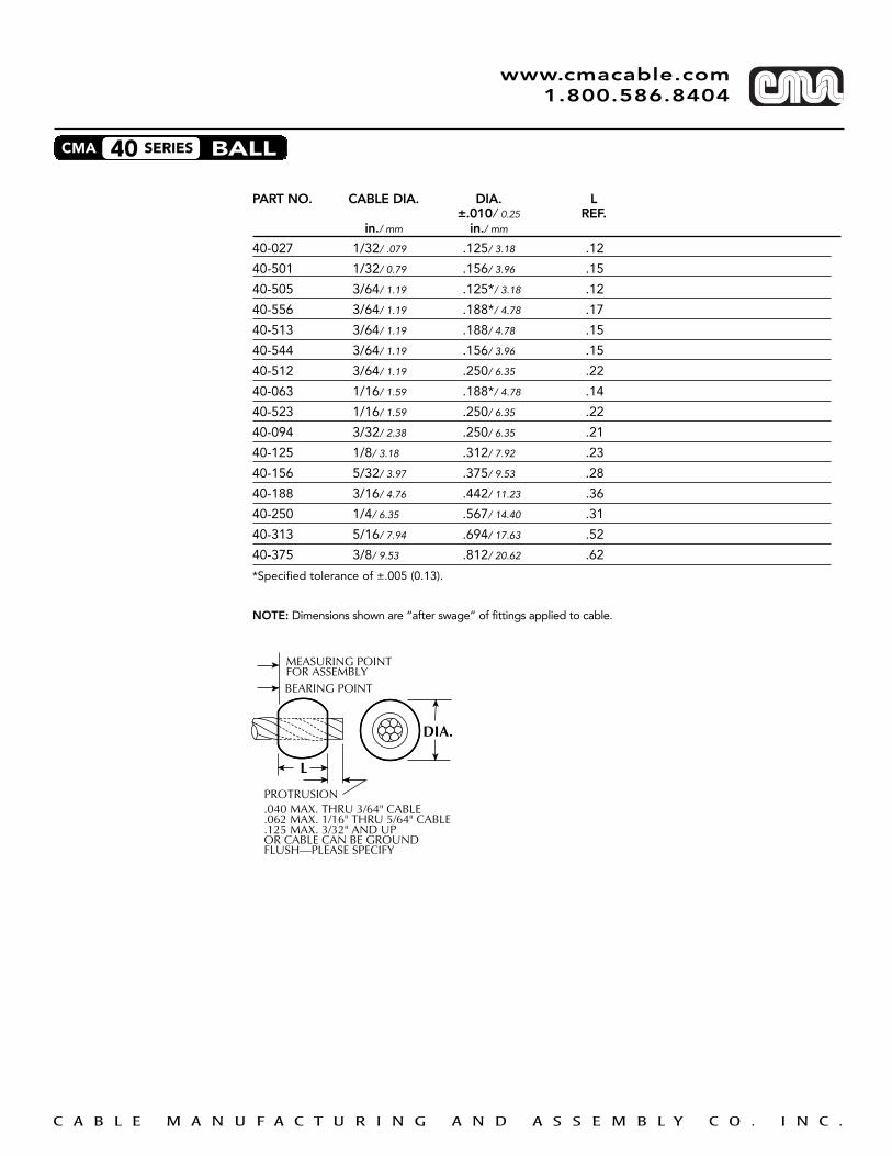
CMA 40 SERIES BALL
MEASURING POINTFOR ASSEMBLYBEARING POINT
L
DIA.
PROTRUSION.040 MAX. THRU 3/64" CABLE.062 MAX. 1/16" THRU 5/64" CABLE.125 MAX. 3/32" AND UPOR CABLE CAN BE GROUNDFLUSH—PLEASE SPECIFY
➤
➤
➤
➤
➤
➤
➤
➤
PART NO. CABLE DIA. DIA. L±.010/ 0.25 REF.
in./ mm in./ mm
40-027 1/32/ .079 .125/ 3.18 .12
40-501 1/32/ 0.79 .156/ 3.96 .15
40-505 3/64/ 1.19 .125*/ 3.18 .12
40-556 3/64/ 1.19 .188*/ 4.78 .17
40-513 3/64/ 1.19 .188/ 4.78 .15
40-544 3/64/ 1.19 .156/ 3.96 .15
40-512 3/64/ 1.19 .250/ 6.35 .22
40-063 1/16/ 1.59 .188*/ 4.78 .14
40-523 1/16/ 1.59 .250/ 6.35 .22
40-094 3/32/ 2.38 .250/ 6.35 .21
40-125 1/8/ 3.18 .312/ 7.92 .23
40-156 5/32/ 3.97 .375/ 9.53 .28
40-188 3/16/ 4.76 .442/ 11.23 .36
40-250 1/4/ 6.35 .567/ 14.40 .31
40-313 5/16/ 7.94 .694/ 17.63 .52
40-375 3/8/ 9.53 .812/ 20.62 .62
*Specified tolerance of ±.005 (0.13).
NOTE: Dimensions shown are “after swage” of fittings applied to cable.

C A B L E M A N U F A C T U R I N G A N D A S S E M B L Y C O . I N C .
www.cmacable.com 1.800.586.8404
CMA 50 SERIES LOOP
L
PIN DIA.(REF.)
BEARING POINT
MEASURING POINTFOR ASSEMBLY
CENTER LINE
DIA.
S(REF.)
NOTE: PLEASE SPECIFY PIN DIA. AND S DIMENSION
PART NO. CABLE DIA. DIA. REF. L. REF.in./ mm
50-031 1/32/ 0.79 .10 .31
50-047 3/64/ 1.19 .15 .47
50-533 3/64/ 1.19 .18 .20
50-063 1/16/ 1.59 .19 .49
50-094 3/32/ 2.38 .25 .62
50-125 1/8/ 3.18 .35 .82
50-156 5/32/ 3.97 .39 .82
50-188 3/16/ 4.76 .47 1.25
50-250 1/4/ 6.35 .59 1.63
50-313 5/16/ 7.94 .72 1.72
Loop fittings available in aluminum or copper, special finishes upon request.Please specify PIN diameter and S dimension.
Note: Dimensions shown are “after swage of fittings applied to cable.

C A B L E M A N U F A C T U R I N G A N D A S S E M B L Y C O . I N C .
www.cmacable.com 1.800.586.8404
CMA 100 SERIES THIMBLE
A D
F
B
C
E
COLD ROLLED TO FITSTEEL STAINLESS CABLE A B C D E F
ZINC PLATED STEEL RANGE REF. REF. REF. REF. REF. REF.Part No. Part No. in./ mm in./ mm
AN 100-01 AN 100-CO1 1/32/0.79 3/64/1.19 .19 1/4 1/8 1/8 .02 3/64
AN 100-03 AN 100-CO3 1/16/1.59 3/32/2.38 .35 43/64 3/16 3/32 .03 5/64
AN 100-04 AN 100-CO4 3/32/2.38 1/8/3.18 .35 45/64 7/32 9/64 .03 5/64
AN 100-05 AN 100-CO5 5/32/3.97 - .40 51/64 7/32 11/64 .03 7/64
AN 100-06 AN 100-CO6 3/16/4.76 - .50 1 5/16 13/64 .03 11/64
AN 100-08 AN 100-CO8 7/32/5.36 1/4/6.35 .70 1-13/32 13/32 17/46 .03 11/64
AN 100-10 AN 100-C10 9/32/7.14 5/16/7.94 .90 1-51/64 7/16 21/64 .04 7/32
AN 100-12 AN 100-C12 3/8/9.53 - 1.00 2 5/8 25/64 .06 17/64
Use with 50 Series Loop fittings for greater strength and wear resistance.

C A B L E M A N U F A C T U R I N G A N D A S S E M B L Y C O . I N C .
www.cmacable.com 1.800.586.8404
CMA 60 SERIES HEX PLUG
➤
➤
➤
➤➤
➤
➤
➤
MEASURING POINTFOR ASSEMBLYBEARING POINT
L
H
PROTRUSION.040 MAX. THRU 3/64" CABLE.062 MAX. 1/16" THRU 5/64" CABLE.125 MAX. 3/32" AND UPOR CABLE CAN BE GROUNDFLUSH—PLEASE SPECIFY
PART NO. CABLE DIA. H L±.010/ 0.25 REF.
in./ mm in./ mm
60-527 1/32/ 0.79 .125/ 3.18 .3160-582 1/32/ 0.79 .140/ 3.56 .1660-684 1/32/ 0.79 .142/ 3.60 .1860-576 3/64/ 1.19 .105/ 2.67 .1860-036 3/64/ 1.19 .130/ 3.30 .3060-694* 3/64/ 1.19 .162/ 4.10 .2560-621 3/64/ 1.19 .142/ 3.60 .1560-752* 3/64/ 1.19 .108/ 2.70 .3260-700* 1/16/ 1.59 .162/ 4.10 .2360-509 1/16/ 1.59 .162/ 4.10 .2560-722* 1/16/ 1.59 .162/ 4.10 .5060-723 1/16/ 1.59 .162/ 4.10 .5060-716 5/64/ 1.98 .162/ 4.10 .2460-615 1/8/ 3.18 .325/ 8.26 .6360-683 1/8/ 3.18 .345/ 8.76 .5160-743 5/32/ 3.97 .433/ 11.00 .6960-698 3/16/ 4.76 .345/ 8.76 .50
*Actual configuration is Ball End Hex Plug.
NOTE: Dimensions shown are “after swage” of fittings applied to cable.
C A B L E M A N U F A C T U R I N G A N D A S S E M B L Y C O . I N C .
www.cmacable.com 1.800.586.8404
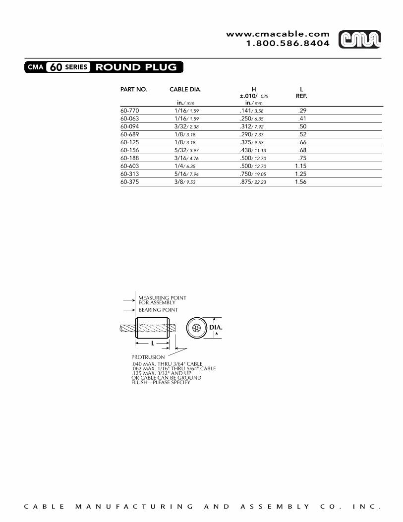
CMA 60 SERIES ROUND PLUG
DIA.
MEASURING POINTFOR ASSEMBLYBEARING POINT
L
➤
➤
➤
➤➤
➤
➤
➤
PROTRUSION.040 MAX. THRU 3/64" CABLE.062 MAX. 1/16" THRU 5/64" CABLE.125 MAX. 3/32" AND UPOR CABLE CAN BE GROUNDFLUSH—PLEASE SPECIFY
PART NO. CABLE DIA. H L±.010/ .025 REF.
in./ mm in./ mm
60-770 1/16/ 1.59 .141/ 3.58 .2960-063 1/16/ 1.59 .250/ 6.35 .4160-094 3/32/ 2.38 .312/ 7.92 .5060-689 1/8/ 3.18 .290/ 7.37 .5260-125 1/8/ 3.18 .375/ 9.53 .6660-156 5/32/ 3.97 .438/ 11.13 .6860-188 3/16/ 4.76 .500/ 12.70 .7560-603 1/4/ 6.35 .500/ 12.70 1.1560-313 5/16/ 7.94 .750/ 19.05 1.2560-375 3/8/ 9.53 .875/ 22.23 1.56

C A B L E M A N U F A C T U R I N G A N D A S S E M B L Y C O . I N C .
www.cmacable.com 1.800.586.8404
CMA 65 SERIES SWAGED BARREL
➤
A
LOCATIONOPTIONAL ➤
➤
➤
➤
➤
➤
L
➤
PROTRUSION:
➤
*CONFIGURATION FOR P/N 65-003
L
➤
➤
➤
➤
➤
➤DIA.
MEASURING POINTFOR ASSEMBLY
BEARING POINT
LOCATIONOPTIONAL
➤
.040 MAX. THRU 3/64” CABLE
.062 MAX. 1/16” THRU 5/64” CABLE
.125 MAX. 3/32” AND UPOR CABLE CAN BE GROUND FLUSH PLEASE SPECIFY*CONFIGURATION FOR P/N 65-005
PART NO. CABLE DIA. A L DIA.REF. + .010/ .025 + .010/ .025
in./ mm in./ mm in./ mm
65-004 .047/ 1.19 - .200/ 5.08 .188/ 4.78
65-005 .063/ 1.60 - .350/ 8.89 .188/ 4.78
65-006* .078/ 1.98 .09 .268/ 6.81 .188/ 4.78
* Offset Swaged Barrel Holding strength varies with fitting size and cable selections. Consult CMA Engineering department for further information.
Note: Dimensions shown are “after swage” of fittings applied to cable.

C A B L E M A N U F A C T U R I N G A N D A S S E M B L Y C O . I N C .
www.cmacable.com 1.800.586.8404
CMA 70 SERIES BALL AND SHANK
MEASURING POINTFOR ASSEMBLY
C
BDIA.
PROTRUSION.040 MAX. THRU 3/64" CABLE.062 MAX. 1/16" THRU 5/64" CABLE.125 MAX. 3/32" AND UPOR CABLE CAN BE GROUNDFLUSH—PLEASE SPECIFY
➤
➤
➤
➤
➤➤
A DIA.
➤
➤
:
➤
PART NO. CABLE DIA. A DIA. B DIA. C+ .010/ .025 + .010/ .025 REF.
in./ mm in./ mm in./ mm
70-047 3.64/ 1.19 .112/ 2.84 .190/ 4.83 .16
70-063 1/16/ 1.59 .112/ 2.84 .190/ 4.83 .16
70-094 3/32/ 2.38 .143/ 3.63 .253/ 6.43 .23
70-125 1/8/ 3.18 .190/ 4.83 .315/ 8.00 .31
70-156 5/32/ 3.97 .222/ 5.64 .379/ 9.63 .39
70-188 3/16/ 4.76 .255/ 6.48 .442/ 11.23 .47
70-250 1/4/ 6.35 .348/ 8.84 .567/ 14.40 .63
70-281 9/32/ 7.14 .382/ 9.70 .632/ 16.05 .75
70-313 5/16/ 7.94 .413/ 10.49 .694/ 17.63 .81
Note: Dimensions shown are “after swage” of fittings applied to cable.

C A B L E M A N U F A C T U R I N G A N D A S S E M B L Y C O . I N C .
www.cmacable.com 1.800.586.8404
CMA 86 SERIES CLEVIS
E
➤
➤
ID THRU
MEASURING POINTFOR ASSEMBLY
➤ ➤ ➤
ID THRU
ID THRU
➤
MEASURING POINTFOR ASSEMBLY ➤
MEASURING POINTFOR ASSEMBLY ➤
➤➤➤
E
➤
➤
E
➤
➤
➤A
➤G DIA.
➤
➤
T
F➤
➤
➤
➤
STYLE #1 STYLE #3
F➤
➤
F
➤
➤
➤
T
➤
T
➤
➤
G DIA.
➤
G DIA.
➤
➤
➤A
➤
➤
➤A
➤ ➤B
➤
➤
H
➤
STYLE #2
PART NO. A B ID E F G. DIA. H T STYLE RECOMMENDEDREF. REF. + .010/ 0.25 REF. REF. + .015/ 0.38 REF. REF. CABLE FITTING
In./ mm in./ mm in./ mm
86-001 1.63 - .531/ 13.49 1.25 .58 .406/ 10.31 - .19 1 1/4/ 6.35 70-250
86-002 1.75 - .656/ 16.66 1.25 .82 .469/ 11.91 - .19 1 5/16/ 7.94 70-313
86-003 1.12 - .315/ 8.00 .75 .48 .268/ 6.81 - .13 2 9/16/ 4.76 70-188
86-004 1.44 - .315/ 8.00 .75 .47 .268/ 6.81 - .13 2 3/16/ 4.76 70-188
86-005 2.40 1.00 .195/ 4.95 .75 .28 .195/ 4.95 .51 .13 3 3/32/ 2.38 70-094
86-006 2.40 1.00 .320/ 8.13 .75 .28 .281/ 7.14 .51 .13 3 3/16/ 4.76 70-188
C A B L E M A N U F A C T U R I N G A N D A S S E M B L Y C O . I N C .
www.cmacable.com 1.800.586.8404
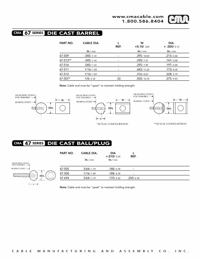
CMA 67 SERIES DIE CAST BARREL
PART NO. CABLE DIA. L W DIA.REF. +0.10/ .025 + .005/ 0.13
in./ mm in./ mm in./ mm
67-509 .045/ 1.14 - .395/ 10.03 .215/ 5.46
67-513** .045/ 1.14 - .290/ 7.37 .141/ 3.58
67-516 .045/ 1.14 - .295/ 7.49 .197/ 5.00
67-511 1/16/ 1.59 - .443/ 11.25 .173/ 4.39
67-512 1/16/ 1.59 - .316/ 8.03 .228/ 5.79
67-507* 1/8/ 3.18 .33 .500/ 12.70 .375/ 9.53
Note: Cable end must be “upset” to maintain holding strength.
CMA 47 SERIES DIE CAST BALL/PLUG
PART NO. CABLE DIA. DIA L+.010/ 0.25 REF.
in./ mm in./ mm
47-505 3/64/ 1.19 .188/ 4.78 -
47-500 1/16/ 1.59 .188/ 4.78 -
47-694 3/64/ 1.19 .170/ 4.32 .250/ 6.35
Note: Cable end must be “upset” to maintain holding strength.
MEASURING POINTFOR ASSEMBLY
BEARING POINT
DIA.
�
�
�
�
�
�
L

C A B L E M A N U F A C T U R I N G A N D A S S E M B L Y C O . I N C .
www.cmacable.com 1.800.586.8404
CMA 87 SERIES DIE CAST Z FITTING
MEASURING POINTFOR ASSEMBLY
L
➤
➤➤
A
B
➤➤
➤➤
DIA.
➤
➤
PART NO. CABLE DIA. DIA. A B L+ .003 + .005 + .005 REF.
in./ mm in./ mm in./ mm in./ mm
87-504 3/64/ 1.19 .143/ 3.6 .250/ 6.35 .312/ 7.92 .763
87-505 3/64/ 1.19 .143/ 3.6 .260/ 6.6 .200/ 5.0 .773
87-507 1/16/ 1.59 .165/ 4.2 .197/ 5.0 .165/ 4.2 .792

LH
A
B
DIA.
➤➤
➤➤
MEASURING POINTFOR ASSEMBLY
➤
➤
➤
➤
➤
➤
➤
PART NO. CABLE DIA. DIA. A B H L+ .003/ 0.12 + .020/ 0.50 + .010/ 0.25 + .005/ 0.12 Ref.
in./ mm in./ mm in./ mm in./ mm in./ mm
88-011 1/32/ 0.79 .140/ 3.55 .340/ 8.63 .200/ 5.08 .120/ 3.04 1.00/ 25.4
88-002 3/64/ 1.14 .140/ 3.55 .340/ 8.63 .200/ 5.08 .120/ 3.04 1.00/ 25.4
88-007 3/64/ 1.14 .156/ 3.96 .164/ 4.2 .184/ 4.7 .142/ 3.6 .690/ 17.5
88-008 3/64/ 1.14 .140/ 3.55 .250/ 6.4 .200/ 5.08 .120/ 3.04 .910/ 23.1
88-003 1/16/ 1.6 .140/ 3.55 .340/ 8.63 .200/ 5.08 .120/ 3.04 1.00/ 25.4
88-012 1/16/ 1.6 .120/ 3.04 .218/ 5.5 .167/ 4.2 .105/ 2.07 .758/ 19.3
88-013 1/8/ 3.18 .187/ 4.76 .187/ 6.05 .157/ 4.0 .156/ 3.96 1.00/ 25.4
CMA 88 SERIES SWAGED Z FITTING
C A B L E M A N U F A C T U R I N G A N D A S S E M B L Y C O . I N C .
www.cmacable.com 1.800.586.8404
C A B L E M A N U F A C T U R I N G A N D A S S E M B L Y C O . I N C .
www.cmacable.com 1.800.586.8404
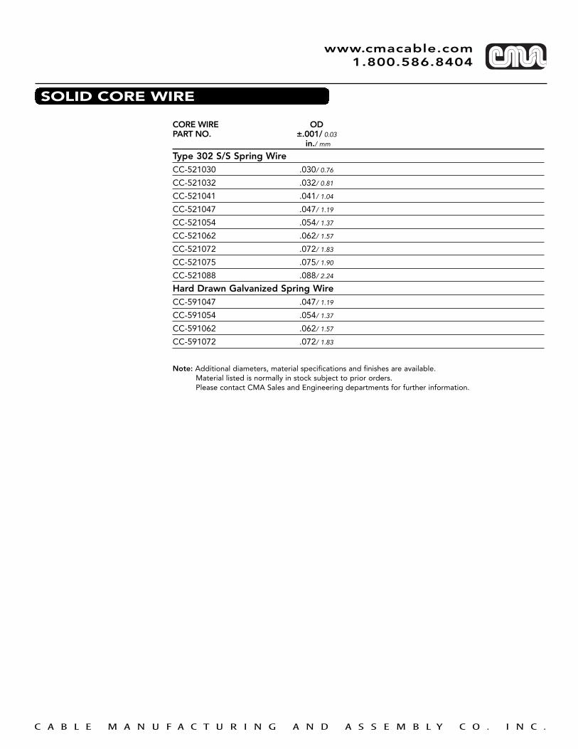
SOLID CORE WIRE
Type 302 S/S Spring WireCC-521030 .030/ 0.76
CC-521032 .032/ 0.81
CC-521041 .041/ 1.04
CC-521047 .047/ 1.19
CC-521054 .054/ 1.37
CC-521062 .062/ 1.57
CC-521072 .072/ 1.83
CC-521075 .075/ 1.90
CC-521088 .088/ 2.24
Hard Drawn Galvanized Spring WireCC-591047 .047/ 1.19
CC-591054 .054/ 1.37
CC-591062 .062/ 1.57
CC-591072 .072/ 1.83
Note: Additional diameters, material specifications and finishes are available. Material listed is normally in stock subject to prior orders.Please contact CMA Sales and Engineering departments for further information.
CORE WIRE ODPART NO. ±.001/ 0.03
in./ mm

C A B L E M A N U F A C T U R I N G A N D A S S E M B L Y C O . I N C .
www.cmacable.com 1.800.586.8404
WIRE CORE TERMINATIONS
Note: 1. Standard diameter for loops is .156”-.205.” Other loop diameters can be supplied. Loop ends are present, are available only with core diameters of .047” and .054”.
2. For “Z” bend standard, X is .170” and Y is .159”. Other X and Y dimensions can be supplied. “Z” bend ends, at present, are available with a core diameter of .030”.
NO BEND
“L” BEND
“Z” BEND
OFFSET LOOP
CENTER LOOP

C A B L E M A N U F A C T U R I N G A N D A S S E M B L Y C O . I N C .
www.cmacable.com 1.800.586.8404
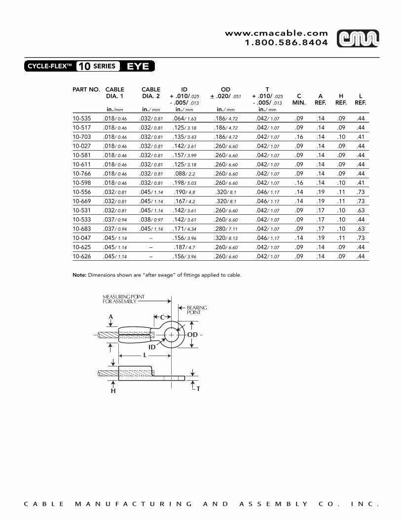
CYCLE-FLEXTM 10 SERIES EYE
PART NO. CABLE CABLE ID OD TDIA. 1 DIA. 2 + .010/.025 + .020/ .051 + .010/ .025 C A H L
- .005/ .013 - .005/ .013 MIN. REF. REF. REF.in./mm in./ mm in./ mm in./ mm in./ mm
10-535 .018/ 0.46 .032/ 0.81 .064/ 1.63 .186/ 4.72 .042/ 1.07 .09 .14 .09 .44
10-517 .018/ 0.46 .032/ 0.81 .125/ 3.18 .186/ 4.72 .042/ 1.07 .09 .14 .09 .44
10-703 .018/ 0.46 .032/ 0.81 .135/ 3.43 .186/ 4.72 .042/ 1.07 .16 .14 .10 .41
10-027 .018/ 0.46 .032/ 0.81 .142/ 3.61 .260/ 6.60 .042/ 1.07 .09 .14 .09 .44
10-581 .018/ 0.46 .032/ 0.81 .157/ 3.99 .260/ 6.60 .042/ 1.07 .09 .14 .09 .44
10-611 .018/ 0.46 .032/ 0.81 .125/ 3.18 .260/ 6.60 .042/ 1.07 .09 .14 .09 .44
10-766 .018/ 0.46 .032/ 0.81 .088/ 2.2 .260/ 6.60 .042/ 1.07 .09 .14 .09 .44
10-598 .018/ 0.46 .032/ 0.81 .198/ 5.03 .260/ 6.60 .042/ 1.07 .16 .14 .10 .41
10-556 .032/ 0.81 .045/ 1.14 .190/ 4.8 .320/ 8.1 .046/ 1.17 .14 .19 .11 .73
10-669 .032/ 0.81 .045/ 1.14 .167/ 4.2 .320/ 8.1 .046/ 1.17 .14 .19 .11 .73
10-531 .032/ 0.81 .045/ 1.14 .142/ 3.61 .260/ 6.60 .042/ 1.07 .09 .17 .10 .63
10-533 .037/ 0.94 .038/ 0.97 .142/ 3.61 .260/ 6.60 .042/ 1.07 .09 .17 .10 .44
10-683 .037/ 0.94 .045/ 1.14 .171/ 4.34 .280/ 7.11 .042/ 1.07 .09 .17 .10 .63
10-047 .045/ 1.14 – .156/ 3.96 .320/ 8.13 .046/ 1.17 .14 .19 .11 .73
10-625 .045/ 1.14 – .187/ 4.7 .260/ 6.60 .042/ 1.07 .09 .14 .09 .44
10-626 .045/ 1.14 – .156/ 3.96 .260/ 6.60 .042/ 1.07 .09 .14 .09 .44
Note: Dimensions shown are “after swage” of fittings applied to cable.

C A B L E M A N U F A C T U R I N G A N D A S S E M B L Y C O . I N C .
www.cmacable.com 1.800.586.8404
PART NO. CABLE CABLE H L B THREADDIA. 1 DIA. 2 ±.010/0..25 REF. MIN.in./ mm in./ mm in./ mm
20-018 .018/ 0.46 .024/ 0.61 .105/ 2.67 1.00 .48 5-40
20-027 .023/ 0.58 .034/ 0.86 105/ 2.67 1.00 .48 5-40
20-650 .027/ 0.69 .034/ 0.86 .065/ 1.65 .80 .41 2-64
20-542 .027/ 0.69 .037/ 0.94 .105/ 2.67 1.28 .70 4-40
20-718 .027/ 0.69 .037/ 0.94 .130/ 3.30 1.35 .86 M4x0.7
20-036 .036/ 0.91 .048/ 1.22 .105/ 2.67 1.00 .48 5-40
20-659 .027/ 0.69 .037/ 0.94 .132/ 3.35 1.50 .94 8-32
20-047 .045/ 1.14 .048/ 1.22 .162/ 4.10 1.00 .38 10-24
20-611 .045/ 1.14 .048/ 1.22 .155/ 3.94 1.18 .47 M4x0.7
20-722 .045/ 1.14 .048/ 1.22 .165/ 4.19 1.25 .75 10-24
20-782 .045/ 1.14 .048/ 1.22 .105/ 2.67 1.25 .68 M3x0.5
NOTES: 1. Dimensions shown are “after swage” of fittings applied to cable.2. Fittings have been designed to fit the largest diameter cable in the range. When used on
smaller diameter cable, lower tensile strength will result. Consult CMA engineering for further information.
H
L
B MINFULL THD'S.
THREAD
MEASURING POINT FOR ASSEMBLY
CYCLE-FLEXTM 20 SERIES THREADED TERMINAL
C A B L E M A N U F A C T U R I N G A N D A S S E M B L Y C O . I N C .
www.cmacable.com 1.800.586.8404
PART NO. CABLE DIA. CABLE DIA. DIA. LDIA. 1 DIA. 2 ±.010/0.13 Ref.in./ mm in./ mm in./ mm
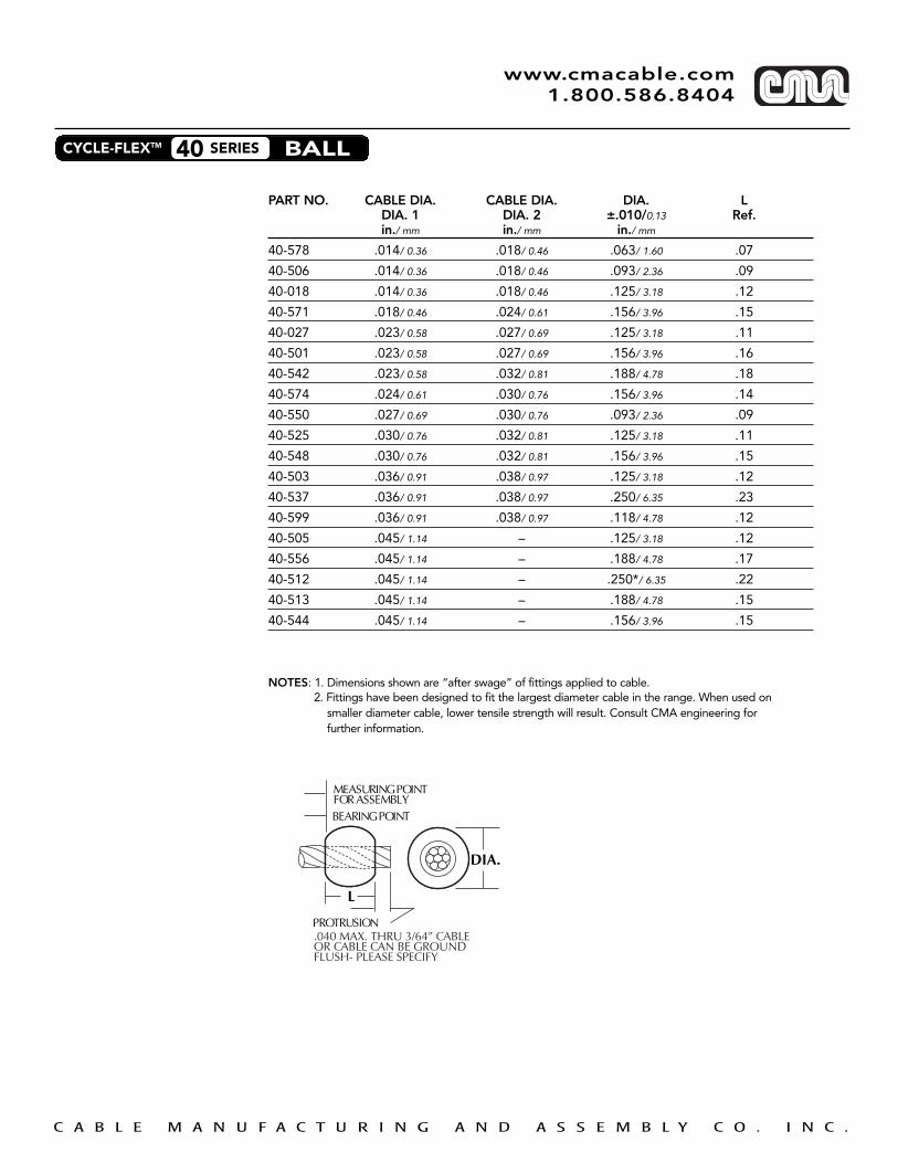
40-578 .014/ 0.36 .018/ 0.46 .063/ 1.60 .07
40-506 .014/ 0.36 .018/ 0.46 .093/ 2.36 .09
40-018 .014/ 0.36 .018/ 0.46 .125/ 3.18 .12
40-571 .018/ 0.46 .024/ 0.61 .156/ 3.96 .15
40-027 .023/ 0.58 .027/ 0.69 .125/ 3.18 .11
40-501 .023/ 0.58 .027/ 0.69 .156/ 3.96 .16
40-542 .023/ 0.58 .032/ 0.81 .188/ 4.78 .18
40-574 .024/ 0.61 .030/ 0.76 .156/ 3.96 .14
40-550 .027/ 0.69 .030/ 0.76 .093/ 2.36 .09
40-525 .030/ 0.76 .032/ 0.81 .125/ 3.18 .11
40-548 .030/ 0.76 .032/ 0.81 .156/ 3.96 .15
40-503 .036/ 0.91 .038/ 0.97 .125/ 3.18 .12
40-537 .036/ 0.91 .038/ 0.97 .250/ 6.35 .23
40-599 .036/ 0.91 .038/ 0.97 .118/ 4.78 .12
40-505 .045/ 1.14 – .125/ 3.18 .12
40-556 .045/ 1.14 – .188/ 4.78 .17
40-512 .045/ 1.14 – .250*/ 6.35 .22
40-513 .045/ 1.14 – .188/ 4.78 .15
40-544 .045/ 1.14 – .156/ 3.96 .15
NOTES: 1. Dimensions shown are “after swage” of fittings applied to cable.2. Fittings have been designed to fit the largest diameter cable in the range. When used on
smaller diameter cable, lower tensile strength will result. Consult CMA engineering for further information.
MEASURING POINTFOR ASSEMBLYBEARING POINT
L
DIA.
PROTRUSION.040 MAX. THRU 3/64” CABLEOR CABLE CAN BE GROUNDFLUSH- PLEASE SPECIFY
CYCLE-FLEXTM 40 SERIES BALL

C A B L E M A N U F A C T U R I N G A N D A S S E M B L Y C O . I N C .
www.cmacable.com 1.800.586.8404
CABLE DIA. H L HDIA. 1 ±.010/ 0.25 Ref. Crossin./ mm in./ mm Section
50-534* .014/ 0.36 .105/ 2.67 .17 Oval
.027/ 0.69
50-014 .018/ 0.46 .063/ 1.60 .23 Hex
50-018 .021/ 0.53 .070/ 1.78 .24 Hex
.024/ .061
50-027 .027/ 0.69 .100/ 2.54 .31 Hex
.030/ 0.76
50-531 .030/ 0.76 .075/ 1.90 .17 Round
.038/ 0.97
50-031 .030/ 0.76 .095/ 2.41 .31 Round
.038/ 0.97
50-047 .045/ 1.14 .145/ 3.68 .47 Round
.048/ 1.22
50-533 .045/ 1.14 .145/ 3.68 .24 Round
.048/ 1.22
Please specify PIN diameter and S dimension.
Note: Dimensions shown are “after swage of fittings applied to cable.
CYCLE-FLEXTM 50 SERIES LOOP

C A B L E M A N U F A C T U R I N G A N D A S S E M B L Y C O . I N C .
www.cmacable.com 1.800.586.8404
PART NO. CABLE DIA. H LDIA. 1 ±.010/ 0.25 Ref.in./ mm in./ mm
40-543 .018/ 0.46 .100/ 2.54 .14
.023/ 0.58
40-526 .027/ 0.69 .141/ 3.58 .18
.030/ 0.76
40-527 .027/ 0.69 .203/ 5.16 .25
.030/ 0.76
40-553 .032/ 0.81 .141/ 3.58 .18
.038/ 0.97
40-552 .032/ 0.81 .203/ 5.16 .24
.038/ 0.97
NOTES: Dimensions shown are “after swage” of fittings applied to cable.
CYCLE-FLEXTM 40 SERIES HEX BALL

C A B L E M A N U F A C T U R I N G A N D A S S E M B L Y C O . I N C .
www.cmacable.com 1.800.586.8404
PART NO. CABLE CABLE H LDIA. 1 DIA. 2 ±.010/0.25 REF.in./ mm in./ mm in./ mm
60-528 .010/ 0.25 .024/ 0.61 .105/ 2.67 .21
60-018 .018/ 0.46 .024/ 0.61 .130/ 3.30 .30
60-582 .023/ 0.58 .030/ 0.76 .140/ 3.56 .16
60-716 .023/ 0.58 .033/ 0.84 .187/ 4.76 .21
60-527 .027/ 0.69 .036/ 0.91 .125/ 3.18 .31
60-027 .027/ 0.69 .036/ 0.91 .130/ 3.30 .30
60-684 .027/ 0.69 .036/ 0.91 .083/ 2.10 .18
60-576 .036/ 0.91 .048/ 1.22 .105/ 2.67 .18
60-036 .037/ 0.94 .048/ 1.22 .130/ 3.30 .30
60-621 .037/ 0.94 .048/ 1.22 .142/ 3.60 .15
NOTES: 1. Dimensions shown are “after swage” of fittings applied to cable.2. Fittings have been designed to fit the largest diameter cable in the range. When used on
smaller diameter cable, lower tensile strength will result. Consult CMA engineering for further information.
➤
➤
➤
➤
➤
➤
➤
MEASURING POINTFOR ASSEMBLYBEARING POINT
L
H
➤
PROTRUSION.040 MAX. THRU 3/64" CABLE.062 MAX. 1/16" THRU 5/64" CABLE.125 MAX. 3/32" AND UPOR CABLE CAN BE GROUNDFLUSH—PLEASE SPECIFY
CYCLE-FLEXTM 60 SERIES HEX PLUG
PART NO. CABLE CABLE H LDIA. 1 DIA. 2 ±.010/ 0.25 REF.in./ mm in./ mm in./ mm
60-608 .010/ 0.25 .027/ 0.69 .125/ 3.18 .40
60-622 .018/ 0.46 .024/ 0.61 .048/ 1.22 .08
60-606 .030/ 0.76 .037/ 0.94 .105/ 2.67 .25
60-609 .030/ 0.76 .037/ 0.94 .130/ 3.30 .41
60-752 .038/ 0.97 .045/ 1.14 .108/ 2.70 .32
60-610 .038/ 0.97 .048/ 1.22 .130/ 3.30 .42
60-611 .047/ 1.19 .062/ 1.57 .130/ 3.30 .42
NOTES: 1. Dimensions shown are “after swage” of fittings applied to cable.2. Fittings have been designed to fit the largest diameter cable in the range. When used on
smaller diameter cable, lower tensile strength will result. Consult CMA engineering for further information.
➤
➤
➤
➤
➤
➤
➤
➤
L H
.062 MAXPROTRUSION
MEASURING POINTFOR ASSEMBLY
BEARING POINT
CYCLE-FLEXTM 60 SERIES RADIUS PLUG

C A B L E M A N U F A C T U R I N G A N D A S S E M B L Y C O . I N C .
www.cmacable.com 1.800.586.8404
PART NO. CABLE DIA. A L DIA.REF. ±.015/ 0.38 ±.010/ 0.25
in./ mm in./ mm in./ mm
65-001 .018/ 0.46 .065/ 1.65 .064/ 1.63
65-002 .031/ 0.79 .250/ 6.35 .116/ 2.95
65-003* .037/ 0.94 .09 .250/ 6.35 .155/ 3.94
65-004 .045/ 1.14 .200/ 5.08 .188/ 4.78
* Offset swaged barrel
NOTES: 1. Dimensions shown are “after swage” of fittings applied to cable.
2. Fittings have been designed to fit the largest diameter cable in the range. When used on smaller diameter cable, lower tensile strength will result. Consult CMA engineering for further information.
A
LOCATIONOPTIONAL
L
PROTRUSION:.040 MAX. THRU 3/64" CABLEOR CABLE CAN BE GROUND FLUSHPLEASE SPECIFY
*CONFIGURATION FOR P/N 65-003
L
DIA.
MEASURING POINTFOR ASSEMBLY
BEARING POINT
LOCATIONOPTIONAL
CYCLE-FLEXTM 65 SERIES SWAGED BARREL

C A B L E M A N U F A C T U R I N G A N D A S S E M B L Y C O . I N C .
www.cmacable.com 1.800.586.8404
PART NO. Max. Length H Thread Min. Dia. BallCable Dia. -.015/ 0.13 ±.005/ 0.13 Full Thd Req’d.
in./ mm in./ mm in./ mm
80-667 .045/ 1.14 .826/ 20.98 .312/ 7.94 M4x.07 .47 .125
80-754 .045/ 1.14 1.000/ 25.40 .187/ 4.75 5-40 .75 .093
80-755 .045/ 1.14 1.120/ 28.45 .250/ 6.35 8-32 .66 .125
80-756 .045/ 1.14 1.250/ 31.75 .281/ 7.14 10-24 .38 .125
80-290 .047/ 1.19 1.000/ 25.40 .187/ 4.75 M3x0.5 .77 .093
Select mating part from Cycle-Flex 20 Series Threaded Terminals.
NOTES: 1. Dimensions shown are “after swage” of fittings applied to cable.
2. Fittings have been designed to fit the largest diameter cable in the range. When used on smaller diameter cable, lower tensile strength will result. Consult CMA engineering for further information.
H
L
MIN. FULL THD
MEASURING POINTFOR ASSEMBLY
CYCLE FLEX 40 SERIESBALL (SPECIFY)
CYCLE-FLEXTM 80 SERIES TURNBUCKLE

C A B L E M A N U F A C T U R I N G A N D A S S E M B L Y C O . I N C .
www.cmacable.com 1.800.586.8404
CONDUIT SPECIFICATIONS
PART NO. ID MAX. MAX. ODREF LINER CABLE DIA SOLID WIRE REF. COATING
in./mm MATERIAL PULL-PULL PULL-PULL in./ mm MATERIALin./ mm in./ mm
Braided ReinforcedC002/C006 .063/1.60 ACE .047/ 1.19 .047/ 1.19 .203/ 5.16 BLK PP/BLK NYLC003/C010 .077/ 1.96 ACE .063/ 1.60 .054/ 1.37 .203/ 5.16 BLK PP/BLK NYLC005 .075/ 1.91 TFE .063/ 1.60 .054/ 1.37 .233/ 5.92 BLK NYLC007 .085/ 2.16 ACE .063/ 1.60 .062/ 1.57 .203/ 5.16 BLK PPC008 .051/ 1.30 ACE .038/ 0.97 .036/ 0.91 .135/ 3.43 BLK NYLC009 .111/ 2.82 ACE .094/ 2.39 .088/ 2.24 .262/ 6.65 BLK PPC015 .063/ 1.60 ACE .047/ 1.19 .047/ 1.19 .170/ 4.32 BLK NYLC019 .105/ 2.67 ACE .078/ 1.98 .088/ 2.24 .220/ 5.60 BLK NYLC023* .075/ 1.90 ACE .063/ 1.60 .054/ 1.37 .203/ 5.16 BLK NYLC024 .077/ 1.96 ACE .063/ 1.60 .054/ 1.37 .203/ 5.16 BLK PEC025 .063/ 1.60 ACE .047/ 1.19 .047/ 1.19 .203/ 5.16 BLK PEBowden-Unlined, Bare/Round WireC403 .087/ 2.21 GAL-RD .063/ 1.60 .062/ 1.57 .195/ 4.95 GAL-RDC404 .110/ 2.79 GAL-RD .094/ 2.39 .088/ 2.24 .260/ 6.60 GAL-RD
Bowden-Unlined, Jacketed/Round WireC601 .079/ 2.01 GAL .063/ 1.60 .062/ 1.57 .235/ 5.97 BLK PVC-RD C602 .110/ 2.79 GAL .094/ 2.39 .088/ 2.24 .319/ 8.10 BLK PVC-RD
Bowden-Lined, Jacketed/Flat or Round WireC705 .075/ 1.90 TFE .063/ 1.60 .054/ 1.37 .217/ 5.50 BLK TPE-FLATC706 .080/ 2.03 PE .063/ 1.60 .062/ 1.57 .203/ 5.16 BLK TPE-FLAT
Long LayC802 .076/ 1.93 PE .063/ 1.60 .062/ 1.57 .197/ 5.00 BLK PPC803 .082/ 2.08 PE .063/ 1.60 .062/ 1.57 .205/ 5.21 BLK PPC804 .086/ 2.18 PE .063/ 1.60 .062/ 1.57 .327/ 8.31 BLK PEC807** .062/ 1.57 PE .047/ 1.19 .047/ 1.19 .203/ 5.16 BLK PE
C808 .150/ 3.81 PE .125/ 3.17 .125/ 3.17 .350/ 8.89 BLK NYL
C810 .091/ 2.31 PE .078/ 1.98 .075/ 1.90 .250/ 5.95 GRY PP
C811 .109/ 2.77 PE .102/ 2.59 .094/ 2.39 .325/ 10.64 GRY PP
C812 .091/ 2.31 PE .078/ 1.98 .075/ 1.90 .325/ 10.64 GRY PP
C813 .109/ 2.77 PE .102/ 2.59 .094/ 2.39 .290/ 7.37 GRY PP*Note: Specified with 24 wire braid—all others specified with 12 wire braid.**Note: This long lay has more flexibility than standard.
NOTE: Recommended maximum cable and solid wire cores are based on the inside diameter of the conduit.Variations in control installations and mounting may require smaller or larger core diameters for proper function.
Legend
LINER:ACE — ACETALPP — POLYPROPYLENETFE — TEFLONNYL — NYLON
WIRE:SS — STAINLESS STEELGAL — GALVANIZED STEELRD — ROUND WIREFLAT — FLAT WIRE
JACKET:PE — POLYETHYLENETPE — THERMOPLASTIC ELASTOMERPVC — POLYVINYL CHLORIDENYL — NYLON
COLOR:BLK — BLACKNTL — NATURALGRY — GRAY

C A B L E M A N U F A C T U R I N G A N D A S S E M B L Y C O . I N C . 1
CMA Remote Actuation Systems ACTUATORS
CMA 11603 – Lever Actuator
• Compact molded housing with vertical lever for fingertip actuation
• Recessed mounting with two bezel holes
• Easily assembled to CMA standard cable controls. Cable fitting permanently snaps into lever handle.
2:1 Mechanical advantage
9/16" (14.3 mm) travel
Material: ABS/glass filled nylon
Color: Black
NOTE: For locking gas spring applications, when used with CMA 11602, 11708, or 12030 – specify a gas spring with quick release valve (1mm travel).
Use Molded End No. 1
CMA 11764 – Mini Lever Actuator
• Molded compact design for recessed mounting
• Contoured handle for easy two-finger operation
• Optional cable control assembly locations for flexible routing in vertical or horizontal applications
• Integral return spring
• Bezel or pocket mounting holes
• Easily assembled to CMA standard cable controls
Position "A" 3.5:1 Mechanical advantage
.750" (19.0 mm) travel
Position “B” 4:1 Mechanical advantage
.750” (19.0 mm) travel
Material: ABS/polycarbonate
Color: Black
Use Molded End No. 4
CL
221/32"
123/32"
11/4"
1/2"
117/32"
19/32"
2.060.020
2.850
.140 DIA.FOR #6 FLAT/OVALHEAD SCREW*
POSITION “B”TRAVEL .750
POSITION “A”TRAVEL .750
1.450 1.390
115/16"
33/4"3.190
31/32"
➤
➤ ➤
➤ ➤
➤
➤
➤
➤
➤
➤
➤
➤➤
➤
➤
➤
BEZEL MOUNTINGHOLES FOR SIDEHOLE MOUNTINGREQUIREMENTS.
* AVAILABLE W/O 1/2
ìA “
“A“
www.cmacable.com 1.800.586.8404

C A B L E M A N U F A C T U R I N G A N D A S S E M B L Y C O . I N C . 2
CMA 11605 – Lever Actuator
• Molded design for recessed mounting with larger lever for ease of actuation
• Optional cable control assembly locations for flexible routing in vertical or horizontal installations or two cable controls at the same time.
• Pocket mounting holes and return spring are standard
• Easily assembled to CMA standard cable controls
Position "A" 2:1 Mechanical advantage
.840" (21.3 mm) travel
Position "B" 1.7:1 Mechanical advantage
1.300" (33.0 mm) travel
Material: ABS/polycarbonate
Color: Black
Use Molded End No. 3
CMA 11604 – Push Button Actuator Round Button/Bezel
• Molded design with large push button for finger or palm actuation
• Adjustable trim ring accommodates mounting surface thickness
• Rear or front surface 4-hole mounting plate
• Integral return spring (optional)
• Supplied assembled to CMA standard cable controls
.480" (12.4 mm) travel
Material: Engineering grade thermo-plastics
Color: Black
NOTE: For locking gas spring applications, when used with CMA 11602, 11708, or 12030 – specify a gas spring with quick release valve (1mm travel).
Use Molded End No. 3
5"
POSITION “B”
.28
1.52
POSITION “A”
2.22
1"3"
➤
➤ ➤
➤ ➤
➤
➤
➤
➤
➤
➤
➤
➤
➤
➤➤➤➤
➤
➤
35/8"
211/16"
227/32"
31/32"
.949 TYP. .949 TYP.
.17 DIA.TYP.
2.52
.75
.59 MIN.
.87 MAX..65
.744
2.08DIA.
MOUNTINGSURFACE
WITH BUTTONDEPRESSED
➤
➤
➤➤
➤
➤
➤
➤➤
➤
➤
➤
➤
➤
➤
➤
➤
➤
➤
➤ ➤
➤ ➤
➤
➤
➤
➤
➤
2"
31/4"
21/2"
25/8"
11/2" DIA.
“A“
“A“
DESIGN GUIDE CMA Remote Actuation Systems ACTUATORS
www.cmacable.com 1.800.586.8404
C A B L E M A N U F A C T U R I N G A N D A S S E M B L Y C O . I N C . 3
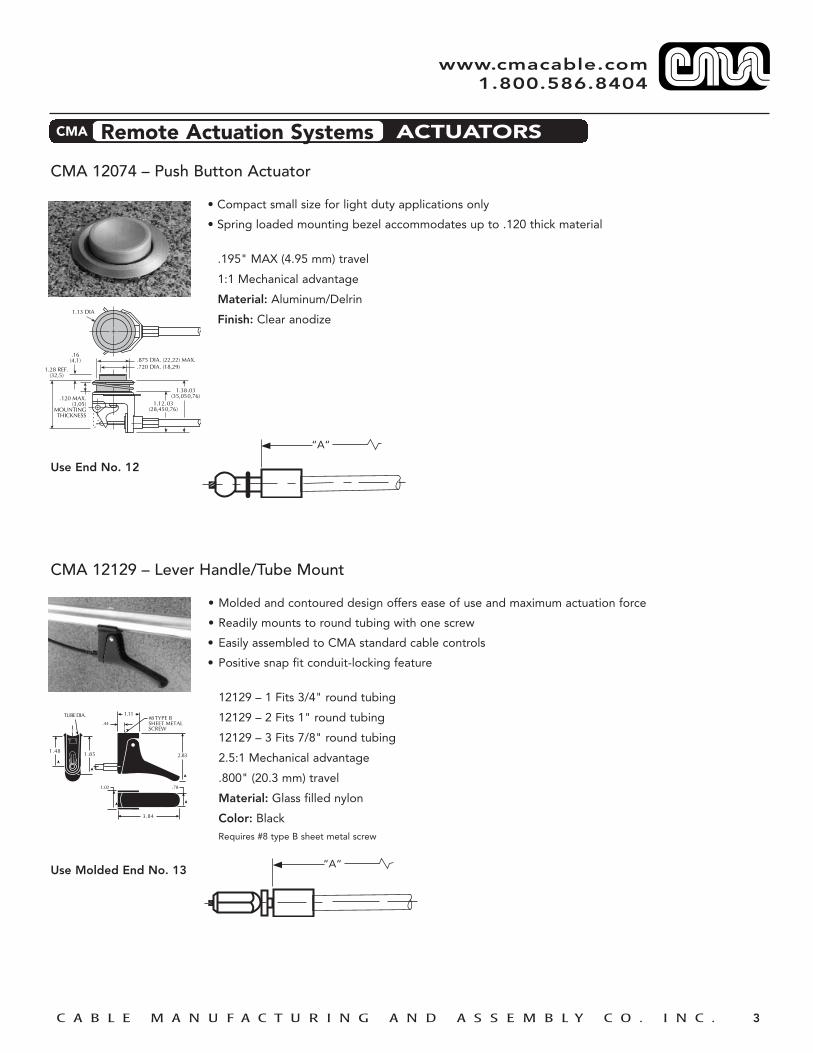
CMA 12074 – Push Button Actuator
• Compact small size for light duty applications only
• Spring loaded mounting bezel accommodates up to .120 thick material
.195" MAX (4.95 mm) travel
1:1 Mechanical advantage
Material: Aluminum/Delrin
Finish: Clear anodize
Use End No. 12
CMA 12129 – Lever Handle/Tube Mount
• Molded and contoured design offers ease of use and maximum actuation force
• Readily mounts to round tubing with one screw
• Easily assembled to CMA standard cable controls
• Positive snap fit conduit-locking feature
12129 – 1 Fits 3/4" round tubing
12129 – 2 Fits 1" round tubing
12129 – 3 Fits 7/8" round tubing
2.5:1 Mechanical advantage
.800" (20.3 mm) travel
Material: Glass filled nylon
Color: BlackRequires #8 type B sheet metal screw
Use Molded End No. 13
.875 DIA. (22,22) MAX.
1.12.03(28,450,76)
1.38.03(35,050,76)
.720 DIA. (18,29)1.28 REF.(32,5)
.16(4,1)
.120 MAX.(3,05)
MOUNTINGTHICKNESS
1.13 DIA
TUBE DIA.
1.481.85
3.84
.78
.44
➤
➤ ➤
➤
➤
➤
1.11#8 TYPE B SHEET METALSCREW
2.83
➤
➤
➤
➤
1.02
➤
➤
➤➤
➤ ➤
➤➤
“A“
“A“
DESIGN GUIDE CMA Remote Actuation Systems ACTUATORS
www.cmacable.com 1.800.586.8404

C A B L E M A N U F A C T U R I N G A N D A S S E M B L Y C O . I N C . 4
CMA 11767 – D-Ring/Bracket
• Molded design with wide D shape configuration for ease of use in straight pull applications
• Shuttle molded 6-hole hanger bracket for easy mounting to flat surfaces
• Square steel handle shaft eliminates rotation
1.25" MAX (31.75 mm) travelMaterial: Polypropylene/Acetal/SteelColor: Black
Use Molded End No. 7
CMA 12073 – T-Handle/Bracket
• Molded design with easy to grip "T" handle for ease of use in straight pull applications
• Shuttle molded 6-hole hanger bracket for easy mounting to flat surfaces
• Square steel handle shaft eliminates rotation
1.25" MAX (31.75 mm) travelMaterial: Polypropylene/Acetal/SteelColor: Black
Use Molded End No. 7
➤ ➤
➤ ➤
➤
➤
➤ ➤
➤➤
➤➤
➤
➤
➤
➤
➤➤
➤
➤
➤
➤
➤➤
1.100
.750
.65
.60"
.375
2"
25/8"
111/16"15/16"
4.7"
5/16"
1"
➤ ➤
➤ ➤
➤
➤
➤ ➤
➤➤
➤
➤
➤
➤
➤➤
➤
➤
➤
➤
➤➤
1.100
.750
3.52
.65
.60"
.375
15/16" 111/16"
21/4"
5/8"
19/16"
“A“
“A“
DESIGN GUIDE CMA Remote Actuation Systems ACTUATORS
www.cmacable.com 1.800.586.8404

C A B L E M A N U F A C T U R I N G A N D A S S E M B L Y C O . I N C . 5
CMA 12169 – Surface Mount Lever Actuator
• Sturdy design with contoured pull up handle
• Easy mounting to the underside of flat surfaces
• Mounting bracket has 2 molded slots for easy installation and adjustment
• Easily assembled to CMA standard cable controls
2.5:1 Mechanical advantage
.625” (15.9 mm) travel
Material: ABS
Color: Black
Use Molded End No. 4
.280”
.200”
2.810”
1.750”
3.450”
1.054”
1.497”
“A“
DESIGN GUIDE CMA Remote Actuation Systems ACTUATORS
www.cmacable.com 1.800.586.8404

C A B L E M A N U F A C T U R I N G A N D A S S E M B L Y C O . I N C . 1
www.cmacable.com 1.800.586.8404
CMA 11602-10 – Locking Gas Spring Operator – 10 MM Rod End
• Molded design for lightweight and ease of assembly
• Used for operating rod end valve stem on locking gas springs
• For use with custom rod end mounting bracket for unique installations
• Designed for intermittent non preload operation of gas spring valve stem
• Readily assembled to CMA standard cable controls
1.57:1 Mechanical advantage
Material: Glass filled nylonColor: Black
NOTE: For locking gas spring applications, when used with CMA 11603 lever, CMA 11604 push button or CMA 11704 push button – specify a gas spring with quick release valve (1mm travel).
Also available: CMA 11602-8 Locking Gas Spring Operator for 8mm Rod End
Use Molded End No. 2or No. 11 for Adjustment
CMA 11708-P110 – Locking Gas Spring Mounting Bracket/Operator – 10 MM Rod End
• Integral swivel mounting bracket and operator
• Accepts 8mm Diameter Mounting pin for commonality with gas spring blade end
• Designed to function with locking gas springs up to 1000N applications
• Easily assembled to CMA standard cable controls
5:1 Mechanical advantageMaterial: CRS SteelFinish: Zinc plating with clear chromate
NOTE: For locking gas spring applications, when used with CMA 11603 lever, CMA 11604 push button or CMA 11704 push button – specify a gas spring with quick release valve (1mm travel).
Also available: CMA 11708P – 108 (8mm), CMA 11708P – 10 (10mm) and 11708P – 8 (8mm) Locking Gas Spring Mounting Bracket/Operators for use on Gas Springs with Straight Valve Pin.
Use Molded End No. 2
2.365
1.56
Ø 8M x 1.0 THDØ 10M x 1.0 THD
.720➤
➤
➤➤
➤➤
➤
GAS SPRINGCL
➤
➤
➤ ➤
➤➤ ➤➤
➤ ➤➤ ➤
➤
➤
➤
➤
➤
➤
➤ ➤
1"
.320 THRU FOR8mm PIN
LEVER
8mm x 1.0 THD. or10mm x 1.0 THD.
BRACKET
3/4"
31/32"2"
111/16
13/16"
3/32"
11/2
11/8
➤➤
GAS SPRING CL CABLECONTROL
CL
“B“TRAVEL
(BASED ON ACTUATOR SELECTED)
“A“
“B“TRAVEL
(BASED ON ACTUATOR SELECTED)
“A“
“A“ “B“TRAVEL
(BASED ON ACTUATOR SELECTED)
No. 2 No. 11
DESIGN GUIDE CMA Remote Actuation Systems OPERATORS
C A B L E M A N U F A C T U R I N G A N D A S S E M B L Y C O . I N C . 2
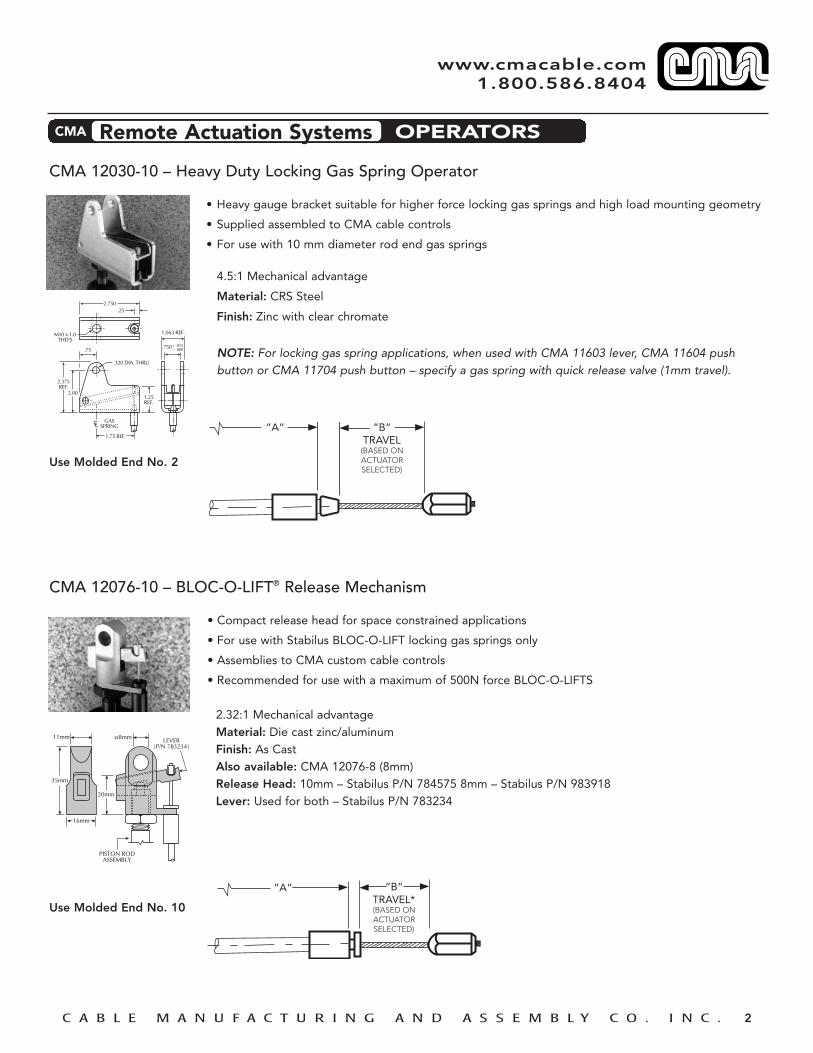
CMA 12030-10 – Heavy Duty Locking Gas Spring Operator
• Heavy gauge bracket suitable for higher force locking gas springs and high load mounting geometry
• Supplied assembled to CMA cable controls
• For use with 10 mm diameter rod end gas springs
4.5:1 Mechanical advantage
Material: CRS Steel
Finish: Zinc with clear chromate
NOTE: For locking gas spring applications, when used with CMA 11603 lever, CMA 11604 push button or CMA 11704 push button – specify a gas spring with quick release valve (1mm travel).
Use Molded End No. 2
CMA 12076-10 – BLOC-O-LIFT® Release Mechanism
• Compact release head for space constrained applications
• For use with Stabilus BLOC-O-LIFT locking gas springs only
• Assemblies to CMA custom cable controls
• Recommended for use with a maximum of 500N force BLOC-O-LIFTS
2.32:1 Mechanical advantage Material: Die cast zinc/aluminumFinish: As CastAlso available: CMA 12076-8 (8mm)Release Head: 10mm – Stabilus P/N 784575 8mm – Stabilus P/N 983918Lever: Used for both – Stabilus P/N 783234
Use Molded End No. 10
GASSPRING
1.75 REF.
1.25REF.
.320 DIA. THRU
1.063 REF.
.750 + .015– .000
M10 x 1.0THD'S
2.375REF.
2.00
.75
2.750.25
CL “B“TRAVEL
(BASED ON ACTUATOR SELECTED)
“A“
DESIGN GUIDE CMA Remote Actuation Systems OPERATORS
www.cmacable.com 1.800.586.8404
11mm LEVER(P/N 783234)
PISTON RODASSEMBLY
20mm
35mm
16mm
ø8mm
“A“ “B“TRAVEL*(BASED ON ACTUATOR SELECTED)

C A B L E M A N U F A C T U R I N G A N D A S S E M B L Y C O . I N C . 3
CMA 12077 – Compact Locking Gas Spring Operator
• For use with special rod end Stabilus BLOC-O-LIFT® locking gas springs in specialty seating applications
• Compact design for space constrained applications
• Supplied assembled to CMA standard cable controls
3.5:1 Mechanical advantage
Material: Glass filled nylon/C1070 Steel
Use End No. 9
CMA 81-222P – Dual Cable Control Adapter
• Design permits multiple actuator or operator use
• Bracket mounts to flat surface with two mounting holes provided
• Easily assembled to CMA standard cable controls
• Used with conduit end No. 6 which provides adjustability to remove cable slack and to balance system
Material: C1010 SteelFinish: Zinc plating with clear chromate
Use Molded End No. 5and End No. 6
.710
1.422
.695
GASSPRING
.84
CL
“A“ “B“TRAVEL
(BASED ON ACTUATOR SELECTED)
DESIGN GUIDE CMA Remote Actuation Systems OPERATORS
www.cmacable.com 1.800.586.8404
➤
➤
➤ ➤
➤
➤
➤
➤
➤
➤
➤➤
➤
➤
➤ ➤
➤➤➤
➤
➤
➤
➤
.312
.75
3/4"
3/8"
31/2"
.080 MAX.
2.0
11/2"
1/2"
1"
3/16" Dia. Typ. 2 Pls.
3/4"
“A“ “B“TRAVEL
(BASED ON ACTUATOR OR
OPERATOR SELECTED)
“A“ “B“TRAVEL
(BASED ON ACTUATOR OR
OPERATOR SELECTED)
No. 5 No. 6
C A B L E M A N U F A C T U R I N G A N D A S S E M B L Y C O . I N C . 4
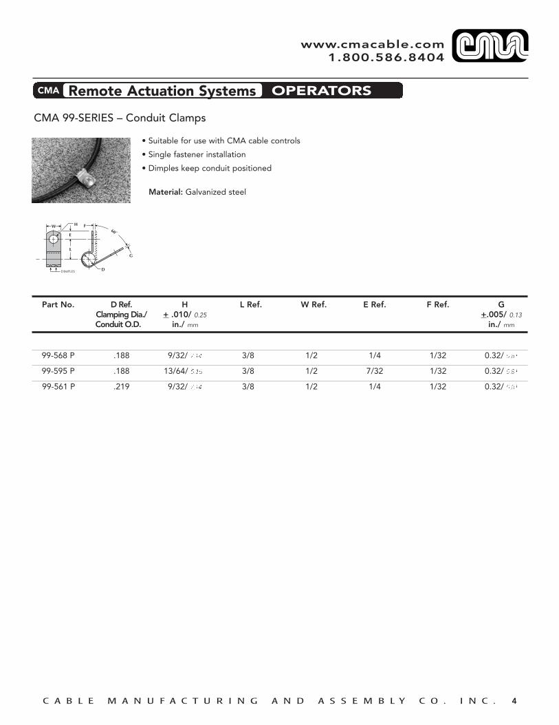
CMA 99-SERIES – Conduit Clamps
• Suitable for use with CMA cable controls
• Single fastener installation
• Dimples keep conduit positioned
Material: Galvanized steel
➤ ➤
➤
L
➤
➤➤
➤
➤
➤
➤
➤
➤
➤➤
Part No.
99-568 P
99-595 P
99-561 P
D Ref.Clamping Dia./Conduit O.D.
.188
.188
.219
H+ .010/ 0.25
in./ mm
9/32/ 7.14
13/64/ 5.16
9/32/ 7.14
L Ref.
3/8
3/8
3/8
W Ref.
1/2
1/2
1/2
E Ref.
1/4
7/32
1/4
F Ref.
1/32
1/32
1/32
G+.005/ 0.13
in./ mm
0.32/ 0.81
0.32/ 0.81
0.32/ 0.81
DESIGN GUIDE CMA Remote Actuation Systems OPERATORS
www.cmacable.com 1.800.586.8404

www.cmacable.com/specs/cma86
C A B L E M A N U F A C T U R I N G A N D A S S E M B L Y C O . I N C . 1
www.cmacable.com 1.800.586.8404
PART NO. RECOMMENDED MAX. MAX. MATERIALCONDUIT Cable Dia. Core Dia.
in./ mm in./ mm
97-509 C002 .047/ 1.19 .047/ 1.19
C006 .047/ 1.19 .047/ 1.19 Nylon-Black
97-521 C003 .063/ 1.60 .054/ 1.37
C007 .063/ 1.60 .062/ 1.57
C010 .063/ 1.60 .054/ 1.37 ylon-Black
CMA 97 SERIES MOLDED FITTINGS
Nylon-Black
Nylon-Black
END COUPLING
END COUPLING PART NO. RECOMMENDED MAX. MAX. MATERIALCONDUIT Cable Dia. Core Dia.
in./ mm in./ mm
97-537 C002 .047/ 1.19 .047/ 1.19
C006 .047/ 1.19 .047/ 1.19 Nylon-Black
97-538 C003 .063/ 1.60 .054/ 1.37
C010 .063/ 1.60 .054/ 1.37
97-539 C015 .047/ 1.19 .047/ 1.19k
97-671 C007 .063/ 1.60 .062/ 1.57k
Nylon-Black
Nylon-Black
END COUPLING PART NO. RECOMMENDED MAX. MAX. MATERIALCONDUIT Cable Dia. Core Dia.
in./ mm in./ mm
97-520 C008 .038/ 0.97 .038/ 0.97 Nylon-Black
SNAP-IN BUSHING PART NO. RECOMMENDED MAX. MAX. MATERIALCONDUIT Cable Dia. Core Dia.
in./ mm in./ mm
97-594 C003 .063/ 1.60 .054/ 1.37 Nylon-Black
C010 .063/ 1.60 .054/ 1.37
97-617 C002 .047/ 1.19 .047/ 1.19
C006 .047/ 1.19 .047/ 1.19
Nylon-Black
Nylon-Black

PART NO. RECOMMENDED MAX. MAX. MATERIALCONDUIT Cable Dia. Core Dia.
in./ mm in./ mm
97-610 C003 .063/ 1.60 .054/ 1.37 Nylon-Glass
C010 .063/ 1.60 .054/ 1.37 Filled Black
www.cmacable.com/specs/cma86
www.cmacable.com 1.800.586.8404
CMA 97 SERIES MOLDED FITTINGS
SNAP-IN BUSHING
SNAP-IN BUSHING
SNAP-IN BUSHING PART NO. RECOMMENDED MAX. MAX. MATERIALCONDUIT Cable Dia. Core Dia.
in./ mm in./ mm
97-522 C005 .047/ 1.19 .054/ 1.37 Nylon-Black
COLLAR PART NO. RECOMMENDED MAX. MAX. MATERIALCONDUIT Cable Dia. Core Dia.
in./ mm in./ mm
97-523 C005 .047/ 1.19 .054/ 1.37 Nylon-Black
PART NO. RECOMMENDED MAX. MAX. MATERIALCONDUIT Cable Dia. Core Dia.
in./ mm in./ mm
97-540 C003 .063/ 1.60 .054/ 1.37 Nylon-Black
C010 .063/ 1.60 .054/ 1.37 Nylon-Black
PUSH-IN BUSHING PART NO. RECOMMENDED MAX. MAX. MATERIALCONDUIT Cable Dia. Core Dia.
in./ mm in./ mm
97-624 C002 .047/ 1.19 .047/ 1.19 NBlack
C006 .047/ 1.19 .047/ 1.19 Nylon-Black
SLOTTED FLAG PART NO. RECOMMENDED MAX. MAX. MATERIALCONDUIT Cable Dia. Core Dia.
in./ mm in./ mm
97-518 C003 .063/ 1.60 .054/ 1.37 Acetal-Black
C007 .063/ 1.60 .062/ 1.57
C010 .063/ 1.60 .054/ 1.37Nylon-Glass
C A B L E M A N U F A C T U R I N G A N D A S S E M B L Y C O . I N C . 2

C A B L E M A N U F A C T U R I N G A N D A S S E M B L Y C O . I N C .
www.cmacable.com 1.800.586.8404
PART NO. CONDUIT L REF. B OD REF.OD REF. BEFORE MIN. BEFORE THREADin./ mm SWAGE in./ mm SWAGE
93-535 .188/ 4.78 1.31 .71/ 18.03 .250 M6x1.0
93-515 .188/ 4.78 1.40 .75/ 19.05 .250 1/4-28
93-543 .203/ 5.16 1.38 .71/ 18.03 .312 5/16-24
93-544 .203/ 5.16 1.38 .71/ 18.03 .312 5/16-24 LH
93-551 .203/ 5.16 1.50 .90/ 22.86 .281 1/4-20
93-552* .203/ 5.16 .85 .35/ 8.9 .281 1/4-20
93-556 .203/ 5.16 1.60 1.00/ 25.4 .312 M6x1.0
93-532 .219/ 5.56 1.35 .75/ 19.05 .312 5/16-24
93-513 .219/ 5.56 2.25 1.50/ 38.10 .312 5/16-24
93-545 .219/ 5.56 2.09 1.38/ 35.05 .375 3/8-24
93-546 .262/ 6.65 1.35 .75/ 19.05 .437 5/16-24
93-533 .262/ 6.65 2.00 1.38/ 35.05 .437 5/16-24
NOTES: 1. Dimensions shown are “before swage”.2. For conduit diameters less than .188 (4.78) contact CMA (Miniature and ultra-light applications.)3. May be used loose or swaged.
CMA 93 SERIES THREADED CONDUIT FITTING
PART NO. CONDUIT L REF. T REF.OD REF. BEFORE THICKNESS A REF. SNAP RINGin./ mm SWAGE OF MOUNTING GROOVE DIM.
95-520 .188/ 4.78 .930 .190 .290 .039x.210 DIA*
95-525 .203/ 5.16 .930 .220 .320 .029x.220 DIA
95-527 .203/ 5.16 .930 .050 .140 .029x.188 DIA
95-529 .203/ 5.16 .860 .150 .250 .029x.220 DIA
95-528 .218/ 5.54 .950 .110 .210 .040x.220 DIA*
95-521 .219/ 5.56 .950 .190 .290 .039x.210 DIA*
95-522 .262/ 6.65 .930 .190 .290 .039x.210 DIA*
NOTES:1. Dimensions shown are “before swage”.
2. For conduit diameters less than .188 (4.78) contact CMA (Miniature and ultra-light applications.)
3. May be used loose or swaged.
CMA 95 SERIES SNAP RING CONDUIT FITTING

C A B L E M A N U F A C T U R I N G A N D A S S E M B L Y C O . I N C .
www.cmacable.com 1.800.586.8404
PART NO. CONDUIT L REF. OD REF.OD REF. BEFORE BEFOREin./ mm SWAGE SWAGE
96-510 .188/ 4.78 1.00 .250
96-511 .188/ 4.78 .875 .312
96-512 .219/ 5.56 .875 .312
96-513 .262/ 6.65 .875 .375
NOTES: 1. Dimensions shown are “before swage”.2. For conduit diameters less than .188 (4.78) contact CMA (Miniature and
ultra-light applications.)3. May be used loose or swaged.
CMA 96 SERIES PLAIN CONDUIT FITTING
CMA 99 SERIES CONDUIT CLAMPS
CUSHIONED PLAIN DIMPLED
PART NO. D REF. H L W E F G SCLAMPING DIA. ±.010/ 0.25 REF. REF. REF. REF. ±.005/0.13 REF. TYPECONDUIT OD in./ mm in./mm
99-568 .188 9/32/ 7.14 3/8 1/2 1/4 1/32 .032/ 0.81 - W/Dimples
99-595 .188 13/64/ 5.16 3/8 1/2 7/32 1/32 .032/ 0.81 - W/Dimples
99-561 .219 9/32/ 7.14 3/8 1/2 1/4 1/32 .032/ 0.81 - W/Dimples
99-547 .250 11/32/ 8.73 19/32 5/8 3/8 1/32 .032/ 0.81 7/16 Cushioned
99-549 .250 11/32/ 8.73 9/16 5/8 3/8 1/32 .032/ 0.81 7/16 Plain
99-599 .250 9/32/ 7.14 17/32 1/2 5/16 1/32 .032/ 0.81 3/8 Cushioned
99-600 .250 11/64/ 4.37 11/32 3/8 3/16 1/16 .032/ 0.81 - Plain
99-597 .319 9/32/ 7.14 17/32 1/2 5/16 1/32 .032/ 0.81 3/8 Plain