cmnr test for 2.5g-5gbase-t - ieee 802 · 8/12/2015 5 defining a cmnr test specification for...
TRANSCRIPT

Larry Cohen
CMNR Test for2.5G/5GBase-T
August 12, 2015

8/12/2015 2
Overview
• Purpose: Define a test setup, procedure, and some test parameters for acommon-mode noise rejection (CMNR) test for 2.5G/5GBase-T– Goal is a PHY test that reproduces the observed RF ingress from a 3 (10)
Volt/meter incident electric field on exposed UTP cabling and verifies properoperation of a data link under this condition
– Eliminate highly variable test conditions in EMC standard immunity tests
• Discussion of the need for a CMNR test in the standard and potential testmethods
• Some CMNR test specifications for 2.5G/5GBase-T with some initialproposals
• Basic description of CMNR test procedure• Description of CMNR test using a coaxial cable (CC) clamp test setup
– CC clamp CMNR sweep test setup– CC clamp CMNR frequency sweep calibration measurement test setup– CC clamp RF envelope rise time measurement test setup
• Some CC clamp coupling measurement results• Some RF envelope rise time measurement results• Observations from CC clamp measurement results• Next steps and discussion points

8/12/2015 3
The Need for a Common-Mode Noise Rejection (CMNR) Test
• Existing EMC radiated immunity standards are designed to test the radiatedinterference tolerance of end terminal equipment, not the data links attached to theequipment
– Conducted immunity testing (IEC 61000-4-6) provides some form common-mode noiserejection (CMNR) testing for the attached data links but only up to 80 MHz (150 kHz to 80 MHz)
– CMNR is indirectly tested during standard EMC radiated immunity testing from 80 MHz to 1000MHz (IEC 61000-4-3)
• Existing EMC radiated and conducted immunity standards tests do not specifyconsistent test conditions for the data links connected to the equipment under test
– EMC standards allow a large amount of latitude and manufacturer's discretion in the selectionof the test configuration for connected data links in both radiated and conducted immunity tests
– Considerable variability of test conditions from differences in test equipment, even whenfollowing EMC test standard to the letter (e.g. signal generator harmonics)
– Considerable variability of external field intensity outside of calibrated 1.5 meter square boxregion defined per IEC 61000-4-3 (radiated immunity testing from 80 MHz to 1000 MHz)
• The addition of a dedicated CMNR to the data standard provides the equivalentchannel impairment of a consistent reproducible conducted and/or radiated immunitytest where the “device” under test is now the connected data link channel
– The CMNR test can address the problems from variable test conditions observed with EMCradiated immunity product testing on 10GBase-T systems
– Test parameters (e.g. frequency points and dwell time) can be optimized for BER test protocols

8/12/2015 4
Possible Methods for Injecting a Common-Mode Test Signal
• Direct injection (good for differential signals, not so good for common-mode signals)– Can inject precise differential signals into each pair independently, or a common-mode signal into one
pair– With same common-mode (CM) signal injected on all four pairs at the same time, test channel becomes
a cable over ground plane where the impedance and coupling are no longer well behaved– Unbalance (component mismatch) in coupling network can cause excessive CM-to-differential
conversion– High coupling loss because need for high-impedance “bridging” across the test channel– Needs external ferrite clamps on AE (auxiliary equipment) side to isolate far-end transceiver link partner– Adds additional connector junction(s) to channel; will degrade channel insertion loss and return loss– Customized test fixture; not available commercially
• EM clamp from IEC 61000-4-6 (not all units work from 80 MHz to 1000 MHz)– Injects same common-mode signal on all four pairs; differential disturber from channel imbalance– Designed to work from 150 kHz to 80 MHz, but some units work up to 1000 MHz– Provides directional coupling above 10 MHz which eliminates need for external ferrite clamps at AE side
to isolate far-end link partner; but needs external ferrite clamps (#75 material) for operation below 10MHz
– Non-intrusive, does not disturb channel or degrade channel insertion loss and return loss– Common EMC test instrument; units available from several different suppliers
• Coaxial cable clamp (originally defined in Annex 40B, enhancements in Annex 113A)– Injects same common-mode signal on all four pairs; differential disturber from channel imbalance– Non-intrusive, does not disturb channel or degrade channel insertion loss and return loss– Needs external ferrite clamps on AE side to isolate far-end transceiver link partner– Some narrowband nulls in the common-mode coupling that must be addressed by the test procedure– Produced by only one supplier (ETS); different versions with slightly different characteristics
8/12/2015 5
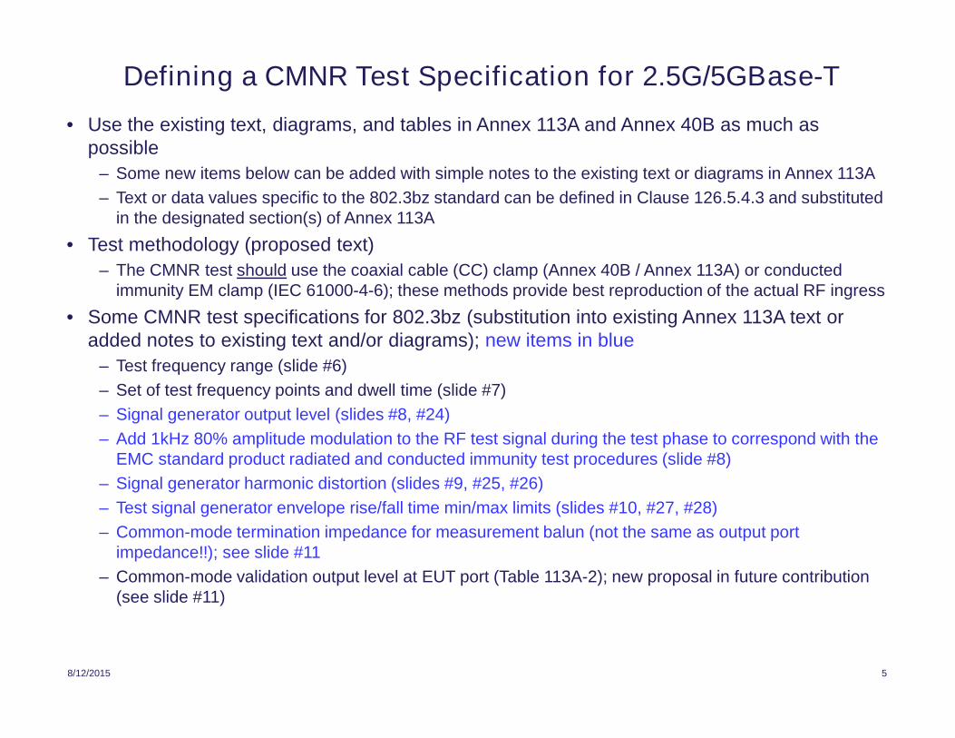
Defining a CMNR Test Specification for 2.5G/5GBase-T
• Use the existing text, diagrams, and tables in Annex 113A and Annex 40B as much aspossible
– Some new items below can be added with simple notes to the existing text or diagrams in Annex 113A
– Text or data values specific to the 802.3bz standard can be defined in Clause 126.5.4.3 and substitutedin the designated section(s) of Annex 113A
• Test methodology (proposed text)
– The CMNR test should use the coaxial cable (CC) clamp (Annex 40B / Annex 113A) or conductedimmunity EM clamp (IEC 61000-4-6); these methods provide best reproduction of the actual RF ingress
• Some CMNR test specifications for 802.3bz (substitution into existing Annex 113A text oradded notes to existing text and/or diagrams); new items in blue
– Test frequency range (slide #6)
– Set of test frequency points and dwell time (slide #7)
– Signal generator output level (slides #8, #24)
– Add 1kHz 80% amplitude modulation to the RF test signal during the test phase to correspond with theEMC standard product radiated and conducted immunity test procedures (slide #8)
– Signal generator harmonic distortion (slides #9, #25, #26)
– Test signal generator envelope rise/fall time min/max limits (slides #10, #27, #28)
– Common-mode termination impedance for measurement balun (not the same as output portimpedance!!); see slide #11
– Common-mode validation output level at EUT port (Table 113A-2); new proposal in future contribution(see slide #11)

8/12/2015 6
Choice of CMNR Test Frequency Range
• EMC standard (IEC 61000-4-3) general purpose radiated immunity test uses the frequencyrange from 80 MHz to 1000 MHz
– Depending upon product requirements (e.g. operating bandwidth), products may be tested up to 6GHz
– The lower 80 MHz limit was selected mainly because of the test equipment limitations for achievingthe necessary uniform field area; need a large test chamber and strong power amplifier below 80 MHz
– CMNR test equipment does not begin to have limitations until below 10 MHz (CC clamp coupling, testbaluns)
• Possible test frequency range options for the CMNR test1. Keep 80 MHz to 1000 MHz test range: Corresponds to general purpose radiated immunity test but
misses some frequency bands (e.g. 30 MHz to 80 MHz) with significant potential interference
2. Set frequency range from 30 MHz to 1000 MHz: 30 MHz is generally considered the demarcationpoint (at least by the FCC) where dominant interference sources change from conducted to radiated,but the CMNR test should consider ingress from conducted interference
3. Set test frequency range from 10 MHz to 1000 MHz: Covers the most of the region of observedingress impairments, but the main reason for the 10 MHz lower limit is to address possible testequipment bandwidth limitations (CC clamp coupling, EM clamp directionality, test baluns, poweramplifiers)
4. Set test frequency range from 1 MHz to 1000 MHz: Covers almost every conceivable ingressimpairment, but may be difficult to implement because of test equipment bandwidth limitations
5. For any of the above lower limits, increase the upper test limit to 2 GHz: More interferers in 1.8 GHz to2.0 GHz now than when 10GBase-T was standardized
• Initial proposal for 802.3bz: Set test frequency range from 10 MHz to 1000 MHz

8/12/2015 7
CMNR Frequency Test Points and Dwell Time
• EMC standard radiated and conducted immunity tests specify a minimumdwell time limit (0.5 second per frequency point) and a maximum frequencystep size (1% of the preceding frequency value), but no specific values foreach parameter– Actual values are determined by the product manufacturer
• Example test point sets– For 10 MHz to 1000 MHz with step = 1% of preceding frequency point 464
points
– For 10 MHz to 1000 MHz with step = 1 MHz 991 points
– For 10 MHz to 1000 MHz with step = 2 MHz 446 points
• Initial proposal for 802.3bz: CMNR test should follow the EMC standardmaximum 1% frequency step size limit, but set the dwell time to provideoptimal accuracy of data link performance (BER) monitoring equipment– Total test time (number of points • dwell time) depends upon data rate and number
of test data packets used in BER test
– Dwell time can vary for different data rates
– For now, dwell time is TBD (need to talk to people who perform actual BER tests)

8/12/2015 8
CMNR Test Signal Generator Output Level
• Test signal generator output level: Must have enough output power toovercome the CM injection device coupling losses and provide the target CMingress level to the test channel with and without modulation.– For the CC and EM clamps, simulating CM ingress at 10 Volts/meter requires more
than +6 dBm clamp input power– Need to specify a minimum signal generator output level and add a note to Annex
113A stating that the signal generator “block” may include an added external poweramplifier
– Initial proposal for 802.3bz: Set minimum signal generator output level to +35dBm
– Proposal based on target CM value in Table 113A-2 using CC clamp with addedmargin (+5 dB) for 1 kHz 80% amplitude modulation (see slide #24)
• Potential problem from CM coupling nulls near 400 MHz in CC clamp (slide#19)– With the proposed output level it will not be possible to properly compensate for the
CM coupling nulls– Depth of null may vary greatly between pairs; full correction may introduce an even
greater error component in some pairs– Possible solution: Place a cap on the output level and provide a best effort correction
• Additional item: Add 1kHz 80% amplitude modulation to the RF testsignal during the CMNR test phase to correspond with the EMC standardproduct RF immunity test procedures (both radiated and conducted).

8/12/2015 9
CMNR Test Signal Generator Harmonic Distortion
• A harmonic distortion specification is required for the signal at the injection deviceinput to eliminate the presence of multiple interferer tones when only one specificinterferer tone should be present
– Inconsistencies in the harmonic distortion (HD) levels of EMC lab signal generatorshave caused ambiguous results in 10GBase-T radiated immunity testing
• The signal generator block (including any external power amplifier) needs anoutput harmonic distortion specification to keep harmonic spurs at least 10 dB (?)below the main carrier
• For 802.3bz the main concern is in the 10 MHz to 200 MHz frequency band
• Initial proposal for 802.3bz: Set maximum level for all for all harmonic spursat the CM injection device input to –35 dBc
– Based upon CC clamp coupling measurements in slides #25, #26
• Standard EMC test signal generator harmonic distortion values for reference(typical values seen in EMC lab equipment)
– Radiated immunity test: HD is typically –15 dBc at the antenna input and –6 dBc for themeasured field strength
– Goal in radiated immunity test is to keep harmonic content low enough to limituncertainty error for the measured field strength
– Conducted immunity: HD of test signal is specified as better than –15 dBc

8/12/2015 10
CMNR Test Signal Envelope Rise/Fall Time Limits
• Problem: For standard EMC immunity tests, some signal generatorsgenerate a wideband transient event when they change frequencies
– Characteristic is equipment dependent and not specified in any EMC teststandards
– These transient events have been observed to cause inconsistent immunity testresults between different EMC labs for 10GBase-T systems
• Proposed solution: Ramp down signal envelope before each test signalfrequency change, and ramp up signal envelope after each test signalfrequency change
– Envelope control can be achieved by an external variable attenuator (see slides#13, #15)
– Eliminates signal generator frequency step transient artifacts which may causefalse error results; more accurate model for real signals
• Initial proposal for 802.3bz: Set test signal envelope rise/fall time from50 to 100 usec
– Proposed values match observed envelope rise/fall time of common radiotransmitters (see slides #27, #28)

8/12/2015 11
Other CMNR Test Specifications
• Common-mode termination impedance for measurement balun– Not the same as the balun common-mode output port impedance
• Problem: In Annex 113A, the CM impedance for each unused pair atduring calibration (validation) is 25 Ohms (both sides terminated with 50Ohms)– This is a good for shielded cable (in 802.3bq), but not for UTP in 802.3bz– Initial 802.3bz proposal: Add a common-mode termination specification
for the measurement balun; specify a CM termination of 50 or 75 Ohms(better value for UTP used in 802.3bz).
– Unused measurement pairs can be properly terminated by “Y” network (seepair termination circuit in slides #14, #15)
• Common-mode validation output level at EUT port (Table 113A-2)– New proposal in future (companion) contribution– Main difference in new proposal is a rolloff of the CM target level above 250
MHz; this rolloff is constant from 80 MHz to 1000 MHz– CM rolloff characteristic matches observed anechoic chamber measurements
(at least to 1000 MHz)– Initial proposal for 802.3bz: Use Table 113A-2

8/12/2015 12
Basic Description of CMNR Test Procedure
• For all test setups, the test procedure is a three step process– Different from clamp noise impairment test in 1000Base-T where the signal injection source
is simply fixed at a specified level
• Validation of injection device electrical parameters (insertion loss and return loss ofsignal injection ports as per Annex 113A.2)
• Calibration phase (measure coupling of injection device to test channel, Annex113A.3)
– Set up test desired test channel; do not turn on other impairment sources (e.g. aliencrosstalk)
– Substitute a 4-pair RJ45-to-SMA breakout/balun test fixture for the MDI port of the EUT
– Use a 4-port vector network analyzer (or fixed-level swept sine wave signal source andpower meter) to measure CM and differential coupling of the injection apparatus to theeach of 4 pairs at the MDI port breakout test fixture; note test signal is not modulated
– Compute difference between measured calibration CM ingress (coupling loss) and targetCM ingress to create a correction table to adjust the RF output level vs. frequency andprovide target CM ingress level at each frequency
• Test phase (inject test signal into test cable channel and monitor performance)– Replace the port under test breakout fixture with the actual PHY port under test
– Initialize data link between the PHY under test and the far-end link partner
– Perform test; sweep the “corrected” signal source and monitor data link performancemetrics; add additional impairments (e.g. 6-around-1 alien crosstalk) as necessary

8/12/2015 13
Coaxial Cable Clamp CMNR Sweep Test Setup
RJ45
2.5G/5G PHYUnder Test
Ferrite clamps(AE decoupling)
L1
Cat 5e/6 UTP patch cordused in test channel (>2m)
L1= 20 cm
RF Signal Generator(10 MHz to 1000 MHz)
RF Out
Metalground plate
50
Patchpanel
Coaxial clamp injects an identicalcommon-mode interference signal intoall four pairs of the test link to simulateradiated interference ingress.
RJ45
RJ45
RJ45
20-95 meterCat 5e/6segment
Cat 5e/6 UTP patch cordused in test channel (2-3m)
Portundertest
50
50
2x61 2x31
Power Amplifier(>20 dB Gain)
Generates both modulated andunmodulated RF carrier signals.
Output level at each frequency adjustedto meet target level using the calibrationsetup and procedure.
Coaxial Cable Clamp(ETS CC-101)
50 Term
2.5G/5G Far-EndLink Partner
Long cable segment maybe 6-around-1 cableconfiguration to allowinjection of alien crosstalk.
2x75
Voltage-ControlledAttenuator
(VCA)
50
50 RF In
RF Out
VCONTROL
EdgeShapingNetwork
RF GatingSignal
Generator
L2
L2= < 2 cm
AE port
Generates VCA control (0-5 Vsquare wave) at one full cyclefor each frequency test point
TWIDTH
= TDWELL
TPERIOD
= TDWELL
+ 0.3 sec
VCA with slow edge control signal limitsRF envelope rise/fall time when the RFsignal changes frequency. Eliminates anysignal generator frequency step transientartifacts (impulse noise).
CMNR test channel is the maximum specified length thatmeets the link segment specification in 802.3 Clause 126.7.All other channel lengths are for diagnostic purposes

8/12/2015 14
Coaxial Cable Clamp CMNR Calibration Measurement Test Setup
EM Coupling Clamp(ETS CC-101)
RJ45-to-SMABreakout andTermination
Fixture 2x61
Logical differential port allows network analyzer tocompute both differential-mode and common-modecoupling in a single (per pair) measurement.
50 50
Agilent E5071A 4-Port Network Analyzer
Logical Port #3(Differential 100 )
Port 1 Port 2 Port 3 Port 4
50
Metal groundplate
Network analyzer measures common-mode anddifferential-mode coupling from the coupling clampinto one of four pairs.
50
All unused pairs on the RJ45Breakout and Termination Box areterminated with 100 Ohms differentialand 75 Ohms common-mode.
Common-mode impedance of logicalport #3 scaled from 25 Ohms to 75Ohms by post-processing
Cat 5e/6/6A UTP patch cordused in test channel (>2m)Test cable approximately 2.5 cm
above the ground plane
Logical Port #2(Single-ended 50 )
Logical Port #1(Single-ended 50 )
2x31 2x75
Ferrite clamps(AE decoupling)
L2< 2 cm
L2
L1
L1
= 20 cm
AE port
RJ45
Shielded RJ45 connector andmetal shield plate bonded tothe metal ground plate
Metalshieldplate
Patchpanel
RJ45
20-95 meterCat 5e/6segment
100 Ohm DM+ 75 Ohm CMTermination
Cat 5e/6 UTP patch cordused in test channel (2-3m)
RJ45
RJ45
1000 pF
49.949.9
49.9
Pairtermination
circuit

8/12/2015 15
CMNR Test (CC Clamp) RF Envelope Rise Time Measurement Test Setup
Ferrite clamps(AE decoupling)
L1
L1 = 20 cm
RF Signal Generator(10 MHz to 1000 MHz)
RF Out
Metalground plate
50
Patchpanel
Coaxial clamp injects an identicalcommon-mode interference signal intoall four pairs of the test link to simulateradiated interference ingress.
RJ45
RJ45
20-95 meterCat 5e/6segment
Cat 5e/6 UTP patch cordused in test channel (2-3m)
50
50
2x61 2x31
Power Amplifier(>20 dB Gain)
Generates both modulated andunmodulated RF carrier signals.
Output level at each frequency adjustedto meet target level using the calibrationsetup and procedure.
Coaxial Clamp(ETS CC-101)
50 Term
2x75
Voltage-ControlledAttenuator
(VCA)
50
50 RF In
RF Out
VCONTROLEdge
ShapingNetwork
RF GatingSignal
Generator
L2
L2
= < 2 cm
AE port
Generates VCA control (0-5 Vsquare wave) at one full cyclefor each frequency test point
TWIDTH
= TDWELL
TPERIOD
= TDWELL
+ 0.3 sec
VCA with slow edge control signal limitsRF envelope rise/fall time when the RFsignal changes frequency. Eliminates anysignal generator frequency step transientartifacts (impulse noise).
100 Ohm DM+ 75 Ohm CMTermination
RJ45
1000 pF
49.949.9
49.9Pairtermination
circuit
All unused pairs on the RJ45Breakout and Termination Boxare terminated with 100 Ohmsdifferential and 75 Ohmscommon-mode.
RJ45-to-SMABreakout andTermination
FixtureRJ45
Metalshieldplate
50
0o
Splitter
Deep MemoryDigital StorageScope (DSO)
CH1
Test cable (Cat5e/6 UTP)approximately 2.5 cmabove the ground plane

August 12, 2015 16

August 12, 2015 17

August 12, 2015 18
August 12, 2015 19

August 12, 2015 20

August 12, 2015 21

August 12, 2015 22
August 12, 2015 23

August 12, 2015 24

August 12, 2015 25

August 12, 2015 26

8/12/2015 27
RF Envelope Transient from FRS Radio Transmitter

8/12/2015 28
RF Envelope Transient from VHF Radio Transmitter

8/12/2015 29
Observations from CC Clamp Measurements• The CC clamp used for these measurements (ETS CC-101) is nearly identical to
the clamp described in Annex 40B, but the copper tube inside diameter is slightlylarger (0.313” vs. 0.250”); this clamp is different from the device described inAnnex 113A
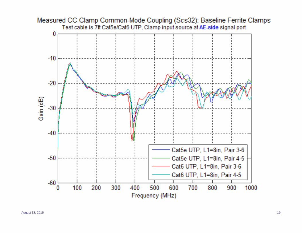
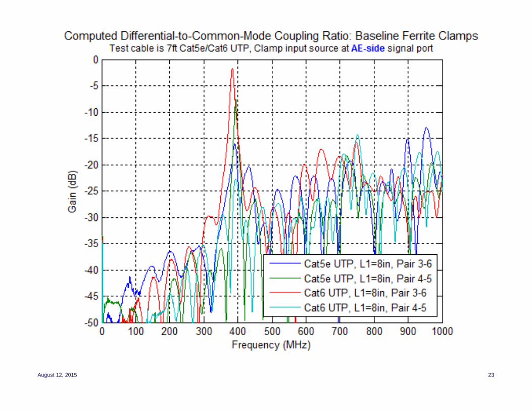
• CM coupling from clamp relatively independent of UTP cabling type (e.g. Cat5e,Cat6) and is more suitable as a baseline RF ingress reference
– Differential mode ingress depends upon cabling type; not useful for calibration purposes
• Injecting test signal at AE-side port reduces depth of coupling nulls and improvestest signal input port return loss; but creates slightly increased coupling loss
• The common-mode coupling in each of four pairs is nearly identical up to 350MHz; this is the optimal range for the CC clamp test setup
• There is a narrow CM coupling null near 400 MHz which cannot be properlycorrected; this null is likely due to the CC clamp physical structure
– Dip appears in this region for both CC-101 and CC-102 clamps– Need to address this in the test procedure– Work pending on reducing this effect by modifying the clamp construction
• The CC clamp coupling is sensitive to the following parameters:– The cable length between the clamp (EUT-side) and the RJ45 break-out board (or EUT)– The height of the test cable above the metal plate ground plane– Proper ground plane contact of the RJ45 break-out board ground (or EUT)– Common-mode termination impedance per pair

8/12/2015 30
Next Steps and Discussion Points
• Should we add a CMNR test to the standard?– Verify operation in the presence of this impairment– Eliminate inconsistencies that occur with EMC standard radiated and conducted immunity
testing
• What frequency test range should we use?• What set of frequency points and dwell time should we use?• Proposed required levels for signal generator output level and harmonic distortion• Common-mode coupling null in CC clamp: Should we simply correct as best
possible (limit max clamp input level) and ignore the residual error?– The error region would be very narrow and likely would not affect the outcome– Depth of null may vary greatly between pair; full correction may introduce an even
greater error component in some pairs– Some work pending on reducing this effect by modifying the CC clamp construction
• Should we add envelope rise/fall time control?– This is actually a better model of real-world signals
• CMNR CM target level: Should we use the current levels in Table 113A?– Alternative proposal in a separate contribution– Given the test channel is maximum length compliant link segment, should the test levels
correspond to a 3 V/meter field or a 10 V/meter external field?
• Build and test a working system; determine construction details• Goal is to have working text by September interim meeting!