cms series sus/sus316 gas mass flowmeters · thank you for purchasing a cms series ... as well as a...
TRANSCRIPT

No. CP-SP-1189E
Thank you for purchasing a CMS Seriesflowmeter.This manual contains information forensuring correct use of the CMS Series.It also provides necessary informationfor installation, maintenance, and trou-bleshooting.This manual should be read by thosewho design and maintain devices thatuse the CMS Series. Be sure to keepthis manual nearby for handy reference.
CMS Series SUS/SUS316Gas Mass Flowmeters
CMS9500/ 0002/ 0005/0020/ 0050/ 0200/ 0500
User's Manual
TM

µFTM
, Micro FlowTM
are trademarks of Azbil Corporation in Japan.
NOTICE
© 2006-2012 Azbil Corporation All Rights Reserved.
Be sure that the user receives this manual before the product is used.
Copying or duplicating this user’s manual in part or in whole is forbid-den. The information and specifications in this manual are subject tochange without notice.
Considerable effort has been made to ensure that this manual is freefrom inaccuracies and omissions. If you should find an error or omis-sion, please contact Azbil Corporation.
In no event is Azbil Corporation liable to anyone for any indirect, specialor consequential damages as a result of using this product.
Please read the "Terms and Conditions" from the following URL beforeordering or use:
http://www.azbil.com/products/bi/order.html

i
About IconsThe safety precautions described in this manual are indicated by various icons.Please be sure you read and understand the icons and their meanings describedbelow before reading the rest of the manual.
Safety precautions are intended to ensure the safe and correct use of this prod-uct, to prevent injury to the operator and others, and to prevent damage to proper-ty. Be sure to observe these safety precautions.
Examples
Triangles warn the user of a possible danger that may be caused bywrongful operation or misuse of this product. These icons graphicallyrepresent the actual danger. (The example on the left warns the user ofthe danger of electric shock.)
White circles with a diagonal bar notify the user that specific actions areprohibited to prevent possible danger. These icons graphically representthe actual prohibited action. (The example on the left notifies the userthat disassembly is prohibited.)
Filled-in black circles instruct the user to carry out a specific obligatoryaction to prevent possible danger. These icons graphically represent theactual action to be carried out. (The example on the left instructs theuser to remove the plug from the outlet.)
SAFETY PRECAUTIONS
WARNING Warnings are indicated when mishandling this product
might result in death or serious injury.
CAUTION Cautions are indicated when mishandling this product
might result in minor injury to the user, or only physical
damage to the product.

ii
WARNING
CAUTIONPrevent foreign matter from entering the device. If rust, water droplets,oil mist, or dust in the pipes enters the device, measurement or controlerror or damage to the device might occur. If there is a possibility offoreign matter entering the device, provide an upstream filter, straineror mist trap capable of eliminating foreign matter 0.1µm or greater indiameter. Be sure to inspect and replace the filter at regular intervals.
If this device is used to monitor gas flow rate to a burner, design pipesand instrumentation so that backfire will not damage the device.
This device is a precision instrument. Since impact might damage it,be careful not to drop or jolt it.
Do not use this device outside of the operating pressure range, orsubject it to pressure above its pressure resistance. Doing so mightdamage it.
When making the pipe connections, fix the flange section of the pipeconnector port in place, and turn the pipe to tighten.
When installing, fasten firmly to prevent vibration.
If using Rc connections, take care not to coat with too much sealant.Foreign matter or burrs in the pipes may cause measurement error.
If this device is used for a flammable gas, mount it on the upstreamside of the safety shutoff valve. If somehow air or oxygen gets into thepipes and an explosive mixture is produced, and if the sensor shouldmake a spark due to lightning or some other reason, the gas mixturein the pipes could explode.
Never allow a gas that is within explosive limits to enter this device.Doing so could cause an explosion.
If a model designed for use with oxygen has been used for othergases, do not use it again for oxygen. Doing so could cause a seriousaccident.
A model designed for some other gas must not be used for oxygen.Such use could result in a serious accident.

iii
CAUTIONBefore connecting pipes with Swagelok or VCR connections, checkthe instructions in the manual provided by the connecting jointmanufacturer.When purchasing a connecting joint, use the following made bySwagelok Co., Ltd:1/4" Swagelok: SS-400-1-6STSC111/2" Swagelok: SS-810-1-8STSC111/4" VCR: SS-4-VCR-1-00032SC113/8" VCR: SS-8-VCR-1-8STSC11 or equivalent
Observe the following when using this flowmeter for oxygen gas:• Piping should be carried out by a specialist experienced in handling
oxygen gas.• Use oil-inhibited pipes and parts.• Be sure to remove foreign matter, burrs, etc. from the pipes before
connecting this flowmeter.• Install a filter upstream of this device.
When carrying or installing this device, never hold it by the resincover. Doing so could damage the cover, or the device could slip andfall, causing an injury.
Mount this device horizontally. If it is mounted vertically, drift mayoccur when the flow rate is zero, resulting in erroneous measurement.
Do not mount with the top surface facing down. Doing so might causemeasurement error or device failure.
When using a relay as the contact for integrated count reset input, usea relay designed for minute currents (with gold contacts). Otherwise,poor contact may cause faulty operation.
If there is a risk of a power surge caused by lightning, use AzbilCorporation's SurgeNon to prevent possible fire or equipment failure.
Be sure to check that the wiring is correct before turning the power on.Incorrect wiring could cause damage or faulty operation.
Do not operate the keys with a mechanical pencil, screwdriver, orother sharp-tipped object. Doing so might cause faulty operation.
Do not remove the resin cover and disassemble the pipe connections.Doing so might cause device failure.
Make sure that the selected analog output type matches the input typeof the receiving device. The output-receiving device could be damagedif the analog output type selection is incorrect.

Organization Used in This Manual
iv
The manual is organized as shown below.
Chapter 1. INTRODUCTION Brief description of this device and its features, as well as a model selection guide.
Chapter 2. NAMES AND FUNCTIONS OF PARTSAn illustration shows the part names and what the parts do.
Chapter 3. MOUNTING AND WIRINGDetails about installation, mounting, wiring and initial settings of this device.
Chapter 4. METHOD OF OPERATIONHow to set up the functions and parameters of this device.
Chapter 5. TROUBLESHOOTINGHow to diagnose and remedy problems that may occur during the operation of this
device.
Chapter 6. SPECIFICATIONSSpecifications and external dimensions of this device, and pressure loss
information.

Contents
v
SAFETY PRECAUTIONSOrganization of This Manual Conventions Used in This Manual
Chapter 1. INTRODUCTION
Introduction • • • • • • • • • • • • • • • • • • • • • • • • • • • • • • • • • • • • • • • • • • • • • • • • • • • • • • • • • • • • • • 1 Features • • • • • • • • • • • • • • • • • • • • • • • • • • • • • • • • • • • • • • • • • • • • • • • • • • • • • • • • • • • • • • • • • 1 Model selection guide• • • • • • • • • • • • • • • • • • • • • • • • • • • • • • • • • • • • • • • • • • • • • • • • • • • • 2
Chapter 2. NAMES AND FUNCTIONS OF PARTS . . . . . . . . . . . . . . . . . . . . . . . . . . . . . . 5
Chapter 3. MOUNTING AND WIRING
Mounting • • • • • • • • • • • • • • • • • • • • • • • • • • • • • • • • • • • • • • • • • • • • • • • • • • • • • • • • • • • • • • • • • 6 Pipes • • • • • • • • • • • • • • • • • • • • • • • • • • • • • • • • • • • • • • • • • • • • • • • • • • • • • • • • • • • • • • • • • • • • • 8 Wiring• • • • • • • • • • • • • • • • • • • • • • • • • • • • • • • • • • • • • • • • • • • • • • • • • • • • • • • • • • • • • • • • • • • 13
Chapter 4. METHOD OF OPERATION
State transition diagrams • • • • • • • • • • • • • • • • • • • • • • • • • • • • • • • • • • • • • • • • • • • • • • • 16 Function setup• • • • • • • • • • • • • • • • • • • • • • • • • • • • • • • • • • • • • • • • • • • • • • • • • • • • • • • • • • 17 Parameter setup • • • • • • • • • • • • • • • • • • • • • • • • • • • • • • • • • • • • • • • • • • • • • • • • • • • • • • • • 21 Display off mode • • • • • • • • • • • • • • • • • • • • • • • • • • • • • • • • • • • • • • • • • • • • • • • • • • • • • • • • 24 Integration • • • • • • • • • • • • • • • • • • • • • • • • • • • • • • • • • • • • • • • • • • • • • • • • • • • • • • • • • • • • • • 24 Resetting the count for integrated flow / integrated flow countdown • • 24 Event standby • • • • • • • • • • • • • • • • • • • • • • • • • • • • • • • • • • • • • • • • • • • • • • • • • • • • • • • • • • 24 Event ON delay • • • • • • • • • • • • • • • • • • • • • • • • • • • • • • • • • • • • • • • • • • • • • • • • • • • • • • • • • 25 Flowrate zero calibration • • • • • • • • • • • • • • • • • • • • • • • • • • • • • • • • • • • • • • • • • • • • • • • 25 Device behavior if the flow rate greatly exceeds the flow rate range • • • 25
Chapter 5. TROUBLESHOOTING
Remedying problems • • • • • • • • • • • • • • • • • • • • • • • • • • • • • • • • • • • • • • • • • • • • • • • • • • • 26
Chapter 6. SPECIFICATIONS
General specifications • • • • • • • • • • • • • • • • • • • • • • • • • • • • • • • • • • • • • • • • • • • • • • • • • • 27 External dimensions • • • • • • • • • • • • • • • • • • • • • • • • • • • • • • • • • • • • • • • • • • • • • • • • • • • • 33 Pressure loss • • • • • • • • • • • • • • • • • • • • • • • • • • • • • • • • • • • • • • • • • • • • • • • • • • • • • • • • • • • 39

Conventions Used in This Manual
vi
The following conventions are used in this manual:
Handling Precautions:Handling precautions indicate items that the user should pay attention towhen handling a CMS Series flowmeter.
Note: Notes indicate information that might benefit the user.
: This indicates the item or page that the user is requested to refer to.
03, 04: This font is used to indicate output on the 7-segment display.
key: This indicates keys on the control panel.

Chapter 1. INTRODUCTION
IntroductionCMS Gas Mass Flowmeters (models 9500, 0002, 0005, 0020, 0050, 0200and 0500) use the µF (Micro Flow) sensor as their sensing element. The µF sensor
is a thermal flow sensor made using proprietary technology. Integrating this ultra-
minute mass flow sensor with high-grade channel design technology has achieved
high accuracy and high rangeability.
Features• Incorporates the µF sensor, made possible by silicon micro-machining and thin-
film technologies. Measuring a mere 1.7mm square and 0.5mm thick, the µF sen-
sor exhibits high sensitivity and quick response.
• Since this device is a mass flowmeter, it is not influenced by temperature or pres-
sure.
• Features a high accuracy of +-3% rdg* (varies depending on the model) and a high
rangeability of 100:1.
Model Range of measurement
CMS9500 5 to 500 mL/min (standard)
CMS0002 0.02 to 2 L/min (standard)
CMS0005 0.05 to 5 L/min (standard)
CMS0020 0.2 to 20 L/min (standard)
CMS0050 0.5 to 50 L/min (standard)
CMS0200 2 to 200 L/min (standard)
CMS0500 5 to 500 L/min (standard)
• Models have extensive functions to suit a wide range of applications: analog out-
put, event output, integrated flow/integrated countdown display, output scaling,
gas type selection, totalizer pulse output, external contact input (for integrated
count reset), and flow rate data serial output.
• Straight pipe sections are not required before and after this device (in case of a
same diameter pipe).
* Rdg (reading) pertains to accuracy expressed as a percentage of the indicated
value. The accuracy varies depending on the model. For details see chapter 6,SPECIFICATIONS.
1

2
Model selection guideThe chart below shows the model numbering system for this flowmeter.
SUS model
*1. L/min (standard) and mL/min (standard) indicate flow rates converted to 20°C,
101.325kPa (atmospheric pressure).
*2. The factory setting is air/nitrogen.
It can be changed to any of the gas types shown below. When gas type is
changed, sometimes the flow rate range changes. Consequently, when selecting
a gas type, make sure to check the "maximum measurable flow rate for each gas
type" in the specifications of the corresponding model.
Appliciable gas types: air/nitrogen, argon, carbon dioxide (CO2), oxygen (gas
type: S only), natural gas 13A (a gas produced from
LNG, of which 88% is methane), methane 100%,
propane 100%, butane
*3. When oxygen (gas type: S) is selected, make sure to specify "1: Gas-contacting
parts treated to be oil-inhibiting" under Optional function. Be aware that use
with oxygen is possible only for model numbers specially designated for oxy-
gen.
Basic Flow rate Model Material Connection Gas Out- Optional function Appended Description
model No. range type method type put 1 2 3 4 No.
CMS Gas Mass Flowmeter
9500 Standard flow rate range 0 to 500mL/min (standard)*1
0002 Standard flow rate range 0 to 2L/min (standard)*1
0005 Standard flow rate range 0 to 5L/min (standard)*1
0020 Standard flow rate range 0 to 20L/min (standard)*1
0050 Standard flow rate range 0 to 50L/min (standard)*1
0200 Standard flow rate range 0 to 200L/min (standard)*1
0500 Standard flow rate range 0 to 500L/min (standard)*1
B Model with display
S SUS (for details, refer to the specifications)
R Rc1/2" (CMS0200/0500)
Rc1/4" (CMS9500/0002/0005/0020/0050)
N Air/nitrogen (Setting can be changed to standard supported gases*2)
S Oxygen*3
2 Output 0 to 5Vdc/1 to 5Vdc/4 to 20mA
0 Without optional function
0 Without optional function
0 Without oil-inhibited treatment
1 Gas-contacting parts treated to be oil-inhibiting
0 Without optional function
D Inspection certificate provided
Y Traceability certification provided
0 Product version
Chapter 1. INTRODUCTION
3
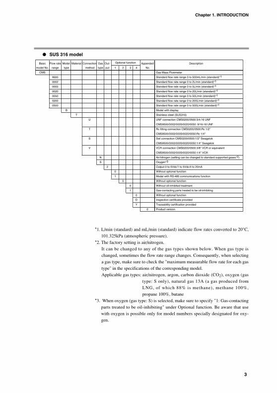
SUS 316 model
*1. L/min (standard) and mL/min (standard) indicate flow rates converted to 20°C,
101.325kPa (atmospheric pressure).
*2. The factory setting is air/nitrogen.
It can be changed to any of the gas types shown below. When gas type is
changed, sometimes the flow rate range changes. Consequently, when selecting
a gas type, make sure to check the "maximum measurable flow rate for each gas
type" in the specifications of the corresponding model.
Applicable gas types: air/nitrogen, argon, carbon dioxide (CO2), oxygen (gas
type: S only), natural gas 13A (a gas produced from
LNG, of which 88% is methane), methane 100%,
propane 100%, butane
*3. When oxygen (gas type: S) is selected, make sure to specify "1: Gas-contacting
parts treated to be oil-inhibiting" under Optional function. Be aware that use
with oxygen is possible only for model numbers specially designated for oxy-
gen.
Basic Flow rate Model Material Connection Gas Out- Optional function Appended Description
model No. range type method type put 1 2 3 4 No.
CMS Gas Mass Flowmeter
9500 Standard flow rate range 0 to 500mL/min (standard)*1
0002 Standard flow rate range 0 to 2L/min (standard)*1
0005 Standard flow rate range 0 to 5L/min (standard)*1
0020 Standard flow rate range 0 to 20L/min (standard)*1
0050 Standard flow rate range 0 to 50L/min (standard)*1
0200 Standard flow rate range 0 to 200L/min (standard)*1
0500 Standard flow rate range 0 to 500L/min (standard)*1
B Model with display
T Stainless steel (SUS316)
U UNF connection CMS0200/0500:3/4-16 UNF
CMS9500/0002/0005/0020/0050: 9/16-18 UNF
T Rc fitting connection CMS0200/0500:Rc 1/2"
CMS9500/0002/0005/0020/0050:Rc 1/4"
S Swl connection CMS0200/0500:1/2" Swagelok
CMS9500/0002/0005/0020/0050:1/4" Swagelok
V VCR connection CMS0200/0500:3/8" VCR or equivalent
CMS9500/0002/0005/0020/0050:1/4" VCR
N Air/nitrogen (setting can be changed to standard supported gases*2)
S Oxygen*3
2 Output 0 to 5Vdc/1 to 5Vdc/4 to 20mA
0 Without optional function
1 Model with RS-485 communications function
0 Without optional function
0 Without oil-inhibited treatment
1 Gas-contacting parts treated to be oil-inhibiting
0 Without optional function
D Inspection certificate provided
Y Traceability certification provided
0 Product version
Chapter 1. INTRODUCTION

4
Accessories (sold separately)
Replacement parts
Chapter 1. INTRODUCTION
Item Model number Remarks
Harness with dedicated 81446594-005 Harness (2m) for model without communications - connector plain wire termination(One harness is required for 81446594-006 Harness (5m) for model without communications - one CMS unit.) plain wire termination
81446594-007 Harness (2m) for model with communications - M3.5 Y-terminals
81446594-008 Harness (5m) for model with communications - M3.5 Y-terminals
Mounting bracket 81446628-001 For CMS9500/0002/0005/0020/005081446721-001 For CMS020081446856-001 For CMS0500
AC adapter 81446957-001 Operating temperature range: 0 to 40˚CHarness connecting 81446594-030AC adapter
Item Model number Remarks
Joint for maintenance 81446834-001 1/4" Rc joint (2)(This joint is intended to replace a damaged 81446834-002 1/2" Rc joint (2)one on an SUS316 model only.) 81446833-001 1/4" Swagelok joint (2)
81446833-002 1/2" Swagelok joint (2)81446895-001 1/4" VCR joint (2)81446895-002 3/8" VCR joint (2)
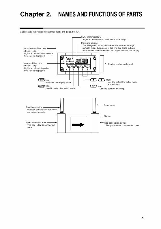
Chapter 2. NAMES AND FUNCTIONS OF PARTS
Names and functions of external parts are given below.
keys: Used to select the setup mode and settings.
ENT key: Used to confirm a setting.
key:Used to select the setup mode.
MODE
Pipe connection outlet: The gas outflow is connected here.
Resin cover
Flange
Signal connector: Provides connections for power and output signals.
Pipe connection inlet: The gas inflow is connected here.
Flow rate display: The 7-segment display indicates flow rate by a 4-digit number. Also, during setup, the first two digits indicate the function, and the second two digits indicate the setting.
EV1, EV2 indicators: Light up when event 1 and event 2 are output.
Display and control panel
Instantaneous flow rate indicator lamp: Lights up when instantaneous flow rate is displayed.
Integrated flow rate indicator lamp: Lights up when integrated flow rate is displayed.
DISP key:Switches the display mode.
Massflow CMS
X10L
L/min
EV2
EV1
ENTMODEDISP
5

6
Chapter 3. MOUNTING AND WIRING
WARNINGIf this device is used for a flammable gas, mount it on the upstream side ofthe safety shutoff valve. If somehow air or oxygen gets into the pipes and anexplosive mixture is produced, and if the sensor should make a spark due tolightning or some other reason, the gas mixture in the pipes could explode.
Never allow a gas that is within explosive limits to enter this device. Doing socould cause an explosion.
If a model designed for use with oxygen has been used for other gases, donot use it again for oxygen. Doing so could cause a serious accident.
A model designed for some other gas must not be used for oxygen. Suchuse could result in a serious accident.
CAUTIONPrevent foreign matter from entering the device. If rust, water droplets, oilmist, or dust in the pipes enters the device, measurement or control error ordamage to the device might occur. If there is a possibility of foreign matterentering the device, provide an upstream filter, strainer or mist trap capableof eliminating foreign matter 0.1µm or greater in diameter. Be sure to inspectand replace the filter at regular intervals.
If this device is used to monitor gas flow rate to a burner, design pipes andinstrumentation so that backfire will not damage the device.
This device is a precision instrument. Since impact might damage it, becareful not to drop or jolt it.
Do not use this device outside of the operating pressure range, or subject itto pressure above its pressure resistance. Doing so might damage it.
When connecting piping, fasten the flange section of the pipe connectorport, and turn the pipe side to connect.
When installing, fasten firmly to prevent vibration.
If using Rc connections, take care not to coat with too much sealant. Foreignmatter or burrs in the pipes may cause measurement error.
Before connecting pipes with Swagelok or VCR connections, check theinstructions in the manual provided by the connecting joint manufacturer.When purchasing a connecting joint, use the following made by SwagelokCo., Ltd:1/4" Swagelok: SS-400-1-6STSC111/2" Swagelok: SS-810-1-8STSC111/4" VCR: SS-4-VCR-1-00032SC113/8" VCR: SS-8-VCR-1-8STSC11 or equivalent

7
Chapter 3. MOUNTING WIRING
CAUTIONDo not remove the resin cover and disassemble pipe connections. Doing somight cause malfunction.
When carrying or installing this device, never hold it by the resin cover.Doing so could damage the cover, or the device could slip and fall, causingan injury.
Mounting
Installation siteAvoid mounting this device in the following locations:
• Where ambient temperature falls below 0˚C or rises above 50˚C
• Where ambient humidity exceeds 90% RH
• Locations subject to sudden changes in temperature and condensation
• In corrosive or flammable gas atmospheres
• Where there are large amounts of conductive substances (e.g. dust, salt or iron
dust), water droplets, oil mist, or organic solvents.
• Locations subject to vibration or shock
• Locations subject to direct sunlight
• Locations splashed by water or rain
• Locations subject to splashing by fluids (e.g. oil, chemicals)
• Locations subject to strong magnetic or electrical fields

8
Pipes
Precautions for piping installationThis device is a precision instrument. If foreign matter such as dust, oil mist or
water enters the device, it may cause measurement error or faulty operation. When
installing piping, be sure to follow the procedures below to prevent foreign matter
from entering the device.
1. Before installing the device, be sure to flush the upstream and downstream piping thorough-
ly to remove welding fume particulate and dust.
2. Be sure to wipe the inside of the pipe to be directly connected to this device.
3. After the above two operations are complete, check to be sure that there is no
welding fume particulate or dust, and then install the device.
Handling Precautions• If foreign matter cannot be fully eliminated by flushing or wiping, or if
the regular presence of foreign matter can be expected, be sure toinstall a filter. If dust, oil or moisture adheres to the metallic mesh orto the Micro Flow sensor chip, measurement error or device failuremay result.
Filter installationFor a dedicated filter, contact the azbil Group.
For applications with compressed air or propane, which
regularly contain oil mist, or applications where rust in the
piping is expected, be sure to install a filter. Recommended
type:
Name : MFF100 series
Specifications: For details, refer to "Lineup of Mist
Separators and Filters for Micro Flow
Sensors," Azbil Corporation specificationssheet CP-SS-1824E.
Chapter 3. MOUNTING WIRING
Restrictor
Flow direction
µF sensor
Metallic meshSpacer

9
Straight pipe sectionIn case of different diameter piping (diameters A and B are different), a straight
pipe section is required.
In case of same diameter piping (diameters A and B are the same), a straight pipe
section is not required.
Handling Precautions• When using a valve that disturbs the gas flow, such as a butterfly
valve, put a 5D straight pipe section between the CMS and the valve.
CMS CMS
A
BB
CMS CMSBA B A
Upstream elbow Downstream elbow
Upstream ball valve (a valve whose structure does not disturb the gas flow)
Downstream ball valve (a valve whose structure does not disturb the gas flow)
A
CMS CMSB B
5D
A A
B B
5D 3D
3D
A ACMS CMS
Upstream side enlarged Downstream side reduced
Different diameter socket Different diameter socket
D indicates the connecting port size. CMS0200/0500: 12mm CMS9500/0002/0005/0020/0050:
CMS CMS
5D
B
BB
5D 3D
3D
AA
B AACMS CMS
Upstream side reduced Downstream side enlarged
Different diameter socket Different diameter socket
6mm
Chapter 3. MOUNTING WIRING

10
Rc connection• Coating sealant
Coat with an appropriate amount of sealant. Do not coat the top two threads of
the screw. Remove any dirt or burrs from inside the pipes.
UNF connection• Connect pipes
Hold the connection port flange with a wrench while connecting the piping.
• Connecting Joints
Hold the connection port flange with a wrench while connecting joints.
Handling Precautions• Do not grip and turn the body.
Doing so might damage thebody or cause leakage.
• When connecting the piping,do not hold the flowmeter bythe resin cover. Doing somight damage the cover.
• Observe the specifiedtightening torque.
Gas flowHandling Precautions• Gas must flow through the meter in
the direction of the arrow on the sideof the f low channel. Flow in theopposite direction cannot be mea-sured accurately.
Gas Gas
Joint
Tigtening torqueCMS9500/0002/0005/0020/0050: 40 to 45N•mCMS0200/0500: 50 to 60N•m
Resin coverFlange
Body
FlangeResin cover
Body
Pipe
Good example Bad example
Sealant Sealant
Chapter 3. MOUNTING WIRING

11
Mounting the flowmeter
• Mounting Position
• Mounting
There are two ways of mounting the flowmeter:
1. Fasten it with two or four screws (depending on the model) from the rear side
using the mounting screw holes on the bottom of the device.
Hole dimensions when mounted directly
Unit: mm
48
27
4.5
48
15
4.5
80
30
5.5
CMS9500/0002/0005/0020/0050
CMS0200
CMS0500
Massflow CMS
X10L
L/min
EV2
EV1
ENTMODEDISP
RIGHT
RIGHT
WRONG
Chapter 3. MOUNTING WIRING
CAUTIONMount this device horizontally. If it is mounted vertically, drift may occurwhen the flow rate is zero, resulting in erroneous measurement.
Do not mount with the top surface facing down. Doing so might causemeasurement error or device failure.

12
2. Using the dedicated mounting bracket (optional), fasten it from the front using
four screws.
Mounting bracket model number:
for CMS9500/0002/0005/0020/0050: 81446628-001
for CMS0200: 81446721-001
for CMS0500: 81446856-001
Mounting bracket
63
78
4.5
48
58
4.5
Hole dimensions when mounting bracket is used
75
80
5.5
Unit: mm
CMS9500/0002/0005/0020/0050
CMS0200
CMS0500
Chapter 3. MOUNTING WIRING
13
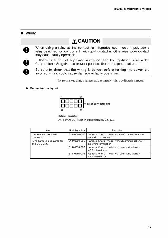
Wiring
We recommend using a harness (sold separately) with a dedicated connector.
Connector pin layout
Mating connector:
DF11-10DS-2C, made by Hirose Electric Co., Ltd.
1
2
9
10
View of connector end
Chapter 3. MOUNTING WIRING
CAUTIONWhen using a relay as the contact for integrated count reset input, use arelay designed for low current (with gold contacts). Otherwise, poor contactmay cause faulty operation.
If there is a r isk of a power surge caused by l ightning, use AzbilCorporation's SurgeNon to prevent possible fire or equipment failure.
Be sure to check that the wiring is correct before turning the power on.Incorrect wiring could cause damage or faulty operation.
Item Model number Remarks
Harness with dedicated 81446594-005 Harness (2m) for model without communications -- connector plain wire termination (One harness is required for 81446594-006 Harness (5m) for model without communications -- one CMS unit.) plain wire termination
81446594-007 Harness (2m) for model with communications --M3.5 Y-terminals
81446594-008 Harness (5m) for model with communications --M3.5 Y-terminals

14
Connector signal names
Connection example
Handling Precautions• Power source GND, instantaneous flow rate output (-), and event
output common lines are all connected inside this device. If theselines are connected to an external device through a common powersupply, interference will cause device failure or faulty operation.
• Take care that the event output does not exceed the output rating ofthis device. If a relay is used, the coil should have a built-in surgeabsorption diode. Otherwise device failure could occur.
1
2
3
4
5
6
7
8
9
10
EV 2 (Gray)
EV 1 (White)
EV COM/SG (Black)
DC OUT + (Brown)
DC OUT - (Red)
V + (Orange)
GND (Yellow)
DA (Pink)
DB (Blue)
D IN (Green)
12 to 24Vdc
Instantaneous flow rate output
Load
Load 30Vdc 50mA or less
Internal circuit Sample external connection
30Vdc 50mA or less
30Vdc or less
RS-485communications
Chapter 3. MOUNTING WIRING
Pin No. Name Description Remarks
1 DC OUT + Instantaneous flow rate output +
2 DC OUT - Instantaneous flow rate output -
3 V + Power + (12 to 24Vdc)
4 GND Power GND
5 DA For RS-485 communications Connect only when RS-485
6 DB model is used.
7 D IN Integrated count reset input
8 EV 2 Event output 2 / Totalizer pulse output
9 EV 1 Event output 1 / Serial data output
10 EV COM/SG Event output common/SG for RS-485

15
Connection of totalizer pulse output to a counter.
• Non-voltage input type
• Voltage input type
Use of flow rate serial data output • Connection example
• Communications protocol
Currently displayed instantaneous flow rate data and totalizer flow data is sent
as ASCII code. "F" and the instantaneous flow rate data is sent first, followed by
"T" and the totalizer flow data.
Example: The instantaneous flow rate is 100. L/min (standard), and the totalizer
flow is 100 x 10L.
• Communications specifications
100. L/min (standard)Instantaneous flow rate
Totalizer flow rate100X10L 0Dh 0Ah
EV1RXD
GND
RTS
CTS
+5V
EV COM
10kΩ+5V10kΩ
RS-232Cdriver
CMS
Interface ComputerRS-232C port
9
10
Counter
Pull-up resistor30Vdc or less
EVCOM
EV28
10
Input
0V
8
10
EV2
EVCOM
Input
0V
Counter
Chapter 3. MOUNTING WIRING
Item Description
Communications system RS-232C, start-stop transmission
Transmission speed 9600bps
Character length 8 bits
Stop bit 2
Parity None
Data transmission cycle 100±10ms

16
Chapter 4. METHOD OF OPERATION
State transition diagramsUpon power-up, with the factory settings, the instantaneous flow rate is displayed
and the instantaneous flow rate indicator lamp lights up.
The diagram below shows the relationship between a change in mode and the
display (in the case of CMS0500).
If the measurement mode (function setup item 02) is set to 01 or 02, the last four
digits of the integrated flow or integrated flow countdown can be displayed by
pressing the key while the instantaneous flow rate is displayed. Pressing
again displays the first four digits of the integrated flow or integrated flow
countdown. Pressing again returns the display to the instantaneous flow rate.
When the power is turned OFF and then back ON again, the display state before
the power was turned OFF resumes.
Handling Precautions• If the key is pressed during setup, the setting returns to its
previous value. • Leave the device powered up for about 30min before use to allow it to
stabilize.
Power ON
Instantaneous flow rate display
DISP key
DISP key
DISP key
Function setupmode Parameter setup
modeMODE key
MODE key
MODE key
DISP key
DISP key
DISP key
DISP key
Integrated flow or integratedflow countdown display, last four digits
Dot display ON
Integrated flow or integrated flow countdown display, first fourdigits
Dot display OFF
DISP key
DISP key
L / min
X10L
L / min
X10L
L / min
X10L
ENT key
key held down for 3s or more+
ENT key
key held down for3s or more
+
ENT key
key helddown for 3s ormore
+
CAUTIONDo not operate the keys with a mechanical pencil, screwdriver, or othersharp-tipped object. Doing so might cause faulty operation.
Make sure that the selected analog output type matches the input type of thereceiving device. The output-receiving device could be damaged if theanalog output type selection is incorrect.

17
Chapter 4. METHOD OF OPERATION
Function setupTo enter the setup mode, press the key. The first two digits on the display
blink. The first two digits identify the function setup item, and the second two
digits indicate the setting for that item.
• Pressing the key moves the display to the next setup item. Pressing the
key moves to the previous setup item.
• Pressing key when 12 is displayed changes the display to 01.*2
• Pressing key when 01 is displayed changes the display to 12.*2
• When the first two digits display the desired setup item, press the key
while it is blinking. This selects the setup item, and the second two digits blink.
• Press the and keys to select the desired setting, and then press
key. All four digits light up.
• Check that the item and the setting are correct.
• The table on the following pages shows all the functions and settings.
*1. Models with the communications function display 30, 31, and 32 in that order
after 12.
*2. For models with a communications function, the number is 32.
key key
key key
key
key
Key lock setup
Measurement mode setup
Event 1 type setup
Low flow cutoff*1

18
Chapter 4. METHOD OF OPERATION
Function setup menu
Item Function Setting Setting description Factory Remarkssetting
0 1 Key lock 00 Key lock disabled 00 When key lock is ON, other 0 1 Lock ON function and parameter
settings can be checked, but cannot be changed.
02 Measurement 00 Only instantaneous flow rate is measured. 01mode 0 1 Instantaneous flow rate and integrated
flow are measured.02 Instantaneous flow rate and integrated
flow countdown are measured.
03 Event 1 type 00 Not used 00 Integrated flow count, (EV1) 0 1 Instantaneous flow rate upper limit value integrated flow countdown,
02 Instantaneous flow rate lower limit value and totalizer pulse output 03 Integrated flow count up settings are 04 Reverse integrated flow count down are effective only when 05 Flow rate data serial output function setup item 02 is 06 Error output set to 0 1 or 02.
04 Event 2 type 00 Not used 00 Integrated flow count (EV2) 0 1 Instantaneous flow rate upper limit value and integrated flow
02 Instantaneous flow rate lower limit value countdown cannot be set 03 Integrated flow count up simultaneously.04 Reverse integrated flow count down05 Totalizer pulse output rate 1(*1)
06 Totalizer pulse output rate 2(*1)
07 Totalizer pulse output rate 3(*1)
05 ON delay setting 00 Disabled 00 Valid only when function (EV1) 0 1 ON 03 is set to 0 1 or 02.
06 ON delay setting 00 Disabled 00 Valid only when function (EV2) 0 1 ON 04 is set to 0 1 or 02.
07 Event standby 00 Disabled 00 Valid only when functionsetting 0 1 ON 03 or 04 is set to 02.
Page 24
08 Gas type 00 Air/nitrogen 00 You can select 03 only when selection 0 1 Argon gas type S (oxygen) is
02 Carbon dioxide (CO2) specified.03 Oxygen When an other gas type is04 City gas 13A (46MJ) specified, you can select05 Methane 100% from among 00, 0 1, 02, 06 Propane 100% 04, 05, 06, 07 08 and 1 1.07 Butane When gas type is changed,08 User specified sometimes flowrate mesurement1 1 City gas 13A (45MJ) rate changed.
Page 28
09 Analog output 00 See the footnote on the right page *2 00 For details, Page 20.scaling 0 1
02
03
04
10 Analog output 00 0 to 5V 00 Make sure that the selected type selection 0 1 1 to 5V analog output type matches
02 4 to 20mA the input type of the receiving device.
1 1 Reference 0 to 35°C (in 1°C intervals), 20temperature 101.325kPa (1atm) standard
00 to35

19
Chapter 4. METHOD OF OPERATION
Item Function Setting Setting description Factory Remarkssetting
12 Low flow cutoff 00 No low flow cutoff 01 If gas type (function setup 08)0 1 Cutoff below the rated minimum display * is set to "user specified"(08), 02 1% FS the low flow cutoff is the 03 2.5% FS amount set here multiplied by 04 5% FS CF, the gas type conversion
(parameter setup P-08).
* The minimum display may vary depending on the model.
Page 30
30 Communications 00 Communication function disabled 00 Only for models with RS-485address 0 1 to Communication address communications.
99
31 Transmission 00 9600bps 00 Only for models with RS-485speed 0 1 4800bps communications.
02 2400bps
32 Data format 00 8 data bits, even parity, 1 stop bit 00 Only for models with RS-4850 1 8 data bits, no parity, 2 stop bits communications.
Item Function Setting CMS9500 CMS0002/0005 CMS0020/0050 CMS0200/0500
04 Event output 2 05 10mL/pulse 1L/pulse 10L/pulse(EV2) 06 100mL/pulse 10L/pulse 100L/pulse
07 1000mL/pulse 100L/pulse 1000L/pulse
*1 Totalizer pulse output rate
Item Function Setting CMS9500 CMS0002 CMS0005 CMS0020 CMS0050 CMS0200 CMS0500
09 Analog output 00 0 to 500 0 to 2 0 to 5 0 to 20 0 to 50 0 to 200 0 to 500scaling 01 0 to 300 0 to 1 0 to 3 0 to 10 0 to 30 0 to 100 0 to 300
02 0 to 200 0 to 0.5 0 to 2 0 to 5 0 to 20 0 to 50 0 to 20003 0 to 100 0 to 0.2 0 to 1 0 to 2 0 to 10 0 to 20 0 to 10004 Desired Desired Desired Desired Desired Desired Desired
scaling scaling scaling scaling scaling scaling scaling
*2 Analog output scaling
The unit for the CMS9500 is mL/min. For other models the unit is L/min.

* Analog output scalingAnalog output can be scaled as shown in the preceding table.
If gas type selection (function setup 08) is changed, the measurable flow rate
range changes as specified on page 32 ("Maximum measurable flow rate for each
gas type"). However, scaling according to the analog output scaling setting will be
applied to the output regardless of what gas type is selected.
Example: For the CMS0050, if gas type (function setup 08) is changed to 02
(carbon dioxide), the measurable flow rate range changes to 0 to 25
L/min. If scaling is set to 01 (0 to 30 L/min), the 0 to 5V output will be
as shown below.
It the output type is 0 to 5V, and if output scaling is used, the maximum output
voltage can be calculated as follows.
• When gas types 00 to 07 or 1 1 are selectedMax. measurable flow rate for the gas
X5VScaling upper limit value
• When gas type 08 is selectedMax. measurable flow rate for the gas
X1
X5VScaling upper limit value Gas type conversion factor
For the maximum measurable flow rate for each gas, see page 28.
The gas type conversion factor is set in parameter setup; see pages 21-24.
5.00
4.16
25 30
Flowrate (L/min)
Voltage output (V)
Measurement rangeof carbon dioxide
20
Chapter 4. METHOD OF OPERATION

21
Chapter 4. METHOD OF OPERATION
Parameter setup
If the key lock function is ON, parameter settings cannot be changed.
To enter the parameter setup mode, hold down the and keys
simultaneously for at least three seconds. If conditions do not allow parameter
setup, "P---" is displayed.
Otherwise, in parameter setup mode, P-** is displayed. The last two digits
identify the parameter setup item.
Pressing the key moves the display to the next setup item. Pressing the
key moves to the previous setup item.
The currently set value for that item is displayed.
If the key is pressed again, the last digit blinks.
If you press the key, the blinking cursor moves to the left. To change the
setting at each of these digits, use the and keys.
To change the setting to the displayed value, press the key.
If event type (function setup 03 or 04) has been set to 03 or 04, the setting of 8-
digit numbers is necessary in P-0 1, 02 and 07. To do this, switch between the
first 4 digits and the last 4 digits as shown below.
Whether parameters P-0 1 to P-09 are displayed for setup depends upon the
function settings. The following tables show the parameters and the necessary
function settings.
Last four digits First four digits
Dot indicates display of last four digits

22
CMS9500
CMS0002/0005
Parameter Description Factory setting Setting range Conditions for display (function settings)
P-01 Event output 1 setting value 0. 0 to 9999 (mL/min ) Item 03 is 0 1 or 02
(EV1) 00000000. 0 to 99999999 (X 10mL) Item 03 is 03 or 04
P-02 Event output 2 setting value 0. 0 to 9999 (mL/min) Item 04 is 0 1 or 02
(EV2) 00000000. 0 to 99999999 (X 10mL) Item 04 is 03 or 04
P-03 EV1 hysteresis 50. 0 to 100 (mL/min) Item 03 is 0 1 or 02
P-04 EV2 hysteresis 50. 0 to 100 (mL/min) Item 04 is 0 1 or 02
P-05 EV1 ON delay 0 0 to 60 (s) Item 03 is 0 1 or 02
P-06 EV2 ON delay 0 0 to 60 (s) Item 04 is 0 1 or 02
P-07 Initial value for integrated 00000000. 0 to 99999999 (X 10mL) Item 02 is 02flow countdown
P-08 Gas type conversion factor 1.000 0.100 to 8.000 Item 08 is 08
P-09 Analog output scaling 100 10 to 250 (%) Item 09 is 04
Parameter Description Factory setting Setting range Conditions for display(function settings)
P-01 Event output 1 setting value 0.000 to 99.99 (L/min)*1 Item 03 is 0 1 or 02
(EV1) 00000000. 0 to 99999999 (L) Item 03 is 03 or 04
P-02 Event output 2 setting value 0.000 to 99.99 (L/min)*1 Item 04 is 0 1 or 02
(EV2) 00000000. 0 to 99999999 (L) Item 04 is 03 or 04
P-03 EV1 hysteresis 0.50*2 0 to 1.00 (L/min)*2 Item 03 is 0 1 or 02
P-04 EV2 hysteresis*3 0.50*2 0 to 1.00 (L/min)*2 Item 04 is 0 1 or 02
P-05 EV1 ON delay 0 0 to 60 (s) Item 03 is 0 1 or 02
P-06 EV2 ON delay 0 0 to 60 (s) Item 04 is 0 1 or 02
P-07 Initial value for integrated 00000000. 00000000 to 99999999 (L) Item 02 is 02flow countdown
P-08 Gas type conversion factor 1.000 0.100 to 8.000 Item 08 is 08
P-09 Analog output scaling 100 10 to 250 (%) Item 09 is 04
Chapter 4. METHOD OF OPERATION

23
Chapter 4. METHOD OF OPERATION
CMS0020/0050
CMS0200/0500
*1 If user-specified gas type is selected in function setup 08, and if the gas type
conversion factor (P-08) is set between 0.100 and 0.499, the range is:
CMS0002 0.000 to 0.995 (in 0.005 increments)
CMS0020 0.00 to 9.95 (in 0.05 increments)
CMS0200 0.0 to 99.5 (in 0.5 increments)
*2 If user-specified gas type is selected in function setup 08, and if the gas type
conversion factor (P-08) is set between 0.100 and 0.499, the range is:
Factory setting Setting range
CMS0002 0.05 0.000 to 0.100 (in 0.005 increments)
CMS0020 0.5 0.00 to 1.00 (in 0.05 increments)
CMS0200 5.0 0.0 to 10.0 (in 0.5 increments)
Handling Precaution• Set a value for event output that is within the measurable range.
Parameter Description Factory setting Setting range Conditions for display(function settings)
P-01 Event output 1 setting value 0.0 0 to 999.9 (L/min(standard))*1 Item 03 is 0 1 or 02
(EV1) 00000000. 0 to 99999999 (L) Item 03 is 03 or 04
P-02 Event output 2 setting value 0.0 0 to 999.9 (L/min)(standard))*1 Item 04 is 0 1 or 02
(EV2) 00000000. 0 to 99999999 (L) Item 04 is 03 or 04
P-03 EV1 hysteresis 5.0 *2 0 to 10.0 (L/min)*2 Item 03 is 0 1 or 02
P-04 EV2 hysteresis 5.0 *2 0 to 10.0 (L/min)*2 Item 04 is 0 1 or 02
P-05 EV1 ON delay 0 0 to 60 (s) Item 03 is 0 1 or 02
P-06 EV2 ON delay 0 0 to 60 (s) Item 04 is 0 1 or 02
P-07 Initial value for integrated 00000000. 0 to 99999999 (L) Item 02 is 02flow countdown
P-08 Gas type conversion factor 1.000 0.100 to 8.000 Item 08 is 08
P-09 Analog output scaling 100 10 to 250 (%) Item 09 is 04
Parameter Description Factory setting Setting range Conditions for display(function settings)
P-01 Event output 1 setting value 0. 0 to 9999 (L/min)*1 Item 03 is 0 1 or 02
(EV1) 00000000. 0 to 99999999 (X 10L) Item 03 is 03 or 04
P-02 Event output 2 setting value 0. 0 to 9999 (L/min)*1 Item 04 is 0 1 or 02
(EV2) 00000000. 0 to 99999999 (X 10L) Item 04 is 03 or 04
P-03 EV1 hysteresis 50.*2 0 to 100 (L/min)*2 Item 03 is 0 1 or 02
P-04 EV2 hysteresis 50.*2 0 to 100 (L/min)*2 Item 04 is 0 1 or 02
P-05 EV1 ON delay 0 0 to 60 (s) Item 03 is 0 1 or 02
P-06 EV2 ON delay 0 0 to 60 (s) Item 04 is 0 1 or 02
P-07 Initial value for integrated 00000000. 0 to 99999999 (X 10L) Item 02 is 02flow countdown
P-08 Gas type conversion factor 1.000 0.100 to 8.000 Item 08 is 08
P-09 Analog output scaling 100 10 to 250 (%) Item 09 is 04

24
Display OFF modeIf the key is held down for at least three seconds, all display is turned off
except for the instantaneous flow rate indicator lamp, which blinks.
TotalizationIf integrated flow exceeds 99999999, the count returns to 0 and counting contin-
ues. When this happens, event output for integrated flow remains OFF until the set
value is reached again.
If the integrated flow countdown reaches 0, counting stops.
Resetting the count for integrated flow / integrated flow countdown To reset the count, hold down the and keys simultaneously for at least
one second while the integrated amount or integrated countdown amount is dis-
played. The integrated flow count is reset to 0, and the countdown is reset to the
default. After reset counting up or counting down resumes.
Event standbyEvent standby operates only on the basis of the instantaneous flow rate lower limit.
This function prevents an erroneous low flow alarm when there is no gas flow
because the device has just started up, for example. After the power is turned ON,
and until the instantaneous flow rate has exceeded the value set for the event lower
limit, there is no event action. After the instantaneous flow lower limit has been
exceeded once, event action operates normally.
Instantaneous flow ratevalue
Lower limit settingvalue
No event action Event action
Time
OFFON
Event output
Chapter 4. METHOD OF OPERATION

25
Event ON delayON delay times (0 to 60s) can be set for both events 1 and 2.
Flowrate zero calibrationIf the indicated flow rate is not zero even though the actual flow rate is zero, and it
seems possible that the sensor's zero point may have shifted, try the following pro-
cedure for flow rate zero calibration.
(1) Display the flow rate or integrated flow amount.
(2) Press and hold the key.
(3) After approx. 10s have elapsed, 0. CAL blinks on the flow rate display.
(4) Press and hold again.
(5) After approx. 1 second, 0. CAL stops blinking and remains lit. The amount of
sensor output at this moment is now treated as zero.
(6) Press key to return to the instantaneous flow rate or integrated flow dis-
play.
Handling Precautions• Use flow rate zero calibration only after ensuring that the flow path
contains only the gas being measured, and after stabilizing the actualflow rate at zero.
Device behavior if the flow rate greatly exceeds the flow rate rangeIf the flow rate exceeds the upper limit, the display might no longer indicate the
correct rate, and the output signal might not be correct. Be sure to use within the
specified flow rate range.
If the flow rate exceeds 120% of the upper limit, the main display alternately indi-
cates flow rate and ALHI. If the flow rate increases further, the ALHI indication goes
out and a flow rate lower than the actual flow rate is displayed. Be careful, because
if the flow rate suddenly becomes excessive, ALHI may not be displayed.
ON delay time
Time
Event detected
Event output
Instantaneousflow rate value
OFF
ON
Event ON
Chapter 4. METHOD OF OPERATION
Flow rate
Flow rate display
Flow rate display
Flow rate display
Upper limit value
120% of upper limit value
Display
Flow rate range
Alternate display of flow rate and ALH1

26
Chapter 5. TROUBLESHOOTING
Remedying problemsRefer to the following table if a problem occurs:
Problem Countermeasure
Nothing on the display. • Make sure that power with the correct voltage and polarity is being supplied.• Make sure that connectors are correctly connected.
ALH 1 is displayed. The instantaneous flow rate has exceeded 120% of the measurement range.Reduce the flow rate so that it is within range, and normal operation willautomatically resume.
Err 1 is displayed. Sensor error• Make sure that gas is not flowing back, or the gas flow direction is not reversed.• Make sure that an excess current is not flowing.If the unit is not restored after turning the power OFF, contact the azbil Groupand ask for repair.
Err2 is displayed. Memory data errorContact the azbil Group and ask for repair.
Signal is output even though • Check the piping for any gas leaks.the flowrate should be zero. • Check the wiring to make sure that it is correct.
• If the device is mounted vertically, mount it horizontally. If it seems possible thatthe sensor's zero point has shifted, try flow rate zero calibration (page 25).
Flow rate has deviated • Check the piping for any gas leaks.excessively. • Check the piping and connection ports for dirt, oil or other foreign matter. If oily,
contact the azbil Group and ask for repair.• Check the wiring to make sure that it is correct.• Check if the flow rate is extremely unstable or greatly exceeds the
measurement range. The displayed value is lower • Check if the gas contains foreign matter such as dust, rust, oil or water.than expected. If it seems that there is foreign matter in the flow meter, contact the azbil GroupThere should be no flow but the and ask for repair.indicated flow rate is higher thanzero.The indicated instantaneous • Check the piping for any gas leaks, and check if the gas flow has actually flow rate is zero, but the stopped. integrated flow counting up or, • Even if the instantaneous flow rate display is 0, a minute flow smaller than the counting down. minimum display value of the flowmeter might be present. For integrated
measurements, even a flow under the minimum display value is counted. Set the low flow cutoff to prevent integrated flow countup or countdown.
Function setup, page 19

27

28
Chapter 6. SPECIFICATIONS
General specifications
Item CMS9500 CMS0002 CMS0005
Compatible gases*1 Air, nitrogen, argon, oxygen, carbon dioxide (CO2), natural gas 13A (LNG base)*2, 100%methane, 100% propane, and 100% butane. The gas must be a dry gas which does notcontain any corrosive component (chlorine, sulfur, acid, etc.). It also must be a clean gas whichdoes not contain dust or oil mist.
Flow rate range for air*3 0 to 500 mL/min (standard) 0 to 2 L/min (standard) 0 to 5 L/min (standard)
L/min (standard) refers to the flow rate after conversion to 20°C, 101.325kPa (1 atmosphere).
Maximum Air/nitrogen 500 mL/min 2 L/min 5 L/min
measured flow Argon 500 mL/min 2 L/min 5 L/min
rate for each gas Carbon dioxide 250 mL/min 1 L/min 3.3 L/min
(at 20°C, Oxygen*4 500 mL/min 2 L/min 5 L/min
101.325kPa) Natural gas 13A 400 mL/min 1.5 L/min 4.5 L/min-46MJ*2
Methane 500 mL/min 2 L/min 5 L/min
Propane 140 mL/min 0.5 L/min 1.7 L/min
Butane 100 mL/min 0.4 L/min 1.25 L/min
Natural gas 13A 400 mL/min 1.5 L/min 4.5 L/min-45MJ*2
Measurement accuracy 5 ≤ χ < 100mL/min 0.02 ≤ χ < 0.4L/min 0.05 ≤ χ <1L/minat 23°C, 101.325kPa ±1% FS ± 1 digit ±1% FS ± 1 digit 1% FS ± 1 digit(χ is the measured flowrate)*5 100 ≤ χ ≤ 500mL/min 0.4 ≤ χ ≤ 2L/min 1 ≤ χ ≤ 5L/min
±3% rdg ± 1 digit 3% rdg ± 1 digit 3% rdg ± 1 digit
Temperature drift From 0 to 75% of flow rate range: ±0.10% FS/°C ± 1 digit or less (in -10 to +60°C range)*6 From 75 to 100% of flow rate range: ±0.15% FS/°C ± 1 digit or less
Pressure drift Applied pressure ±0.1% FS / 0.1 MPa ± 1 digit or less ±0.25% FS / 0.1 MPa *7 of 0 to 1.0 MPa ±1 digit or less
Negative applied ±0.2% FS / 0.01 MPa ± 1 digit or lesspressure of -0.07 to 0 MPa
Operating temperature range -10 to +60°C
Storage temperature range -20 to +70°C
Operating humidity range 10 to 90% RH (without condensation)
Operating pressure range -0.07 to +1.0 MPa
Pressure resistance 1.5MPa
Connection aperture/ SUS model: Rc 1/4"Connection standard SUS316 model: 9/16-18 UNF, Rc 1/4", 1/4" Swagelok, 1/4" VCR (select one suitable for the
model No.)
Body material SUS model: SUS303 and SUS316SUS316 model: SUS316
Case material Polycarbonate
Mounting position Horizontal mounting. (Top surface must not face down.) If this device is mounted vertically,drift may cause erroneous measurement when the actual flow rate is zero. For details, contactthe azbil Group.
Rated voltage 12 to 24Vdc
Supply voltage range 11.4 to 25.2Vdc
Current consumption 100mA max.
Sampling cycle 100ms ± 10ms

29
Chapter 6. SPECIFICATIONS
CMS0020 CMS0050 CMS0200 CMS0500
Air, nitrogen, argon, oxygen, carbon dioxide (CO2), natural gas 13A (LNG base)*2, 100% methane, 100% propane, and 100%butane. The gas must be a dry gas which does not contain any corrosive component (chlorine, sulfur, acid, etc.). It also must be aclean gas which does not contain dust or oil mist.
0 to 20 L/min (standard) 0 to 50 L/min (standard) 0 to 200 L/min (standard) 0 to 500 L/min (standard)
L/min (standard) refers to the flow rate after conversion to 20°C, 101.325kPa (1 atmosphere).
20 L/min 50 L/min 200 L/min 500 L/min
20 L/min 50 L/min 200 L/min 500 L/min
10 L/min 25 L/min 100 L/min 250 L/min
20 L/min 50 L/min 200 L/min 500 L/min
15 L/min 40 L/min 150 L/min 400 L/min
20 L/min 50 L/min 200 L/min 500 L/min
5 L/min 14 L/min 50 L/min 140 L/min
5 L/min 12 L/min 50 L/min 120 L/min
15 L/min 40 L/min 150 L/min 400 L/min
0.2 ≤ χ < 2L/min 0.5 ≤ χ < 5L/min 2 ≤ χ < 20L/min 5 ≤ χ < 50L/min±1% FS ± 1 digit ±1% FS ± 1 digit 1% FS ± 1 digit 1% FS ± 1 digit2 ≤ χ ≤ 20L/min 5 ≤ χ ≤ 50L/min 20 ≤ χ ≤ 200L/min 50 ≤ χ ≤ 500L/min±3% rdg ± 1 digit ±3% rdg ± 1 digit ±3% rdg ± 1 digit ±3% rdg ± 1 digit
From 0 to 75% of flow rate range: ±0.10% FS/°C ± 1 digit or lessFrom 75 to 100% of flow rate range: ±0.15% FS/°C ± 1 digit or less
±0.2% FS / 0.1 MPa ±0.1% FS / 0.1 MPa ±0.2% FS / 0.1 MPa ±1 digit or less±1 digit or less ±1 digit or less
±0.2% FS / 0.01MPa ± 1digit or less
-10 to +60°C
-20 to +70°C
10 to 90% RH (without condensation)
-0.07 to +1.0 MPa
1.5MPa
SUS model: Rc 1/4" SUS303: Rc 1/2"SUS316 model: 9/16-18 UNF, Rc 1/4", 1/4" Swagelok, 1/4" VCR SUS316 model: 3/4-16 UNF, Rc 1/4", 1/2" Swagelok, 3/8" VCR
(select one suitable for the model No.) (select one suitable for the model No.)
SUS model: SUS303 and SUS316SUS316 model: SUS316
Polycarbonate
Horizontal mounting. (Top surface must not face down.) If this device is mounted vertically, drift may cause erroneousmeasurement when the actual flow rate is zero. For details, contact the azbil Group.
12 to 24Vdc
11.4 to 25.2Vdc
100mA max.
100ms ± 10ms

30
Chapter 6. SPECIFICATIONS
Item CMS9500 CMS0002 CMS0005
Display Flow rate display 4-digit 7-segment LED, selectable between instantaneous flow rate and integrated flow display.
Instantaneous Min. display 1 mL/min 0.01 L/min (0.005 L/min)*8 0.01 L/min
flow rate Resolution 1 mL/min 0.01 L/min (0.005 L/min)*8 0.01 L/min
Integrated Display unit 10 mL 1 L
flow rate Display range 0 to 99999999
Data storage Data is written to memory every 10 minutes.(Integrated flow count or countdown can be reset by control panel key or external contact input.)
Indicator LEDs Instantaneous flow rate display, integrated flow display, event 1 & 2 display
Output signal If 0-5 or 1-5Vdc is selected:(instantaneous flowrate output) • Allowable load resistance 250kΩ min.
• Even if the measurement range is exceeded, output remains less than 6V.
If 4-20mAdc is selected: • Allowable load resistance 300Ω max. • Even if the measurement range is exceeded, output remains
less than 24mA.
Output scaling function*9 Selectable from 0 to 100, 0 to 200, Selectable from 0 to 0.2, Selectable from 0 to 1, 0 to 2,0 to 300, 0 to 500mL/min. 0 to 0.5, 0 to 1, 0 to 2 L/min. 0 to 3, 0 to 5 L/min.Factory setting: 0 to 500mL/min. Factory setting: 0 to 2 L/min. Factory setting: 0 to 5 L/min.
Event output Number of outputs 2
Type Open collector (absolute maximum ratings 30Vdc, 50mA)
Totalizer pulse 100ms ± 10%output width
Totalizer pulse 10, 100, 1000mL/pulse 1, 10, 100L/pulseoutput weight
External input Number of inputs 1 (dedicated to reset of integrated count)
Remote circuit Circuit type on other side: No-voltage contact or open collectortype Contact OFF terminal voltage: 4.5 ± 1V
Contact ON terminal current: Approx. 0.5mA (current flowing to contact)Allowable ON contact resistance: 250Ω max.Allowable OFF contact resistance: 100kΩ min.Allowable ON residual voltage: 0.8V max. (open collector on other side)Allowable OFF leakage current: 50µA max. (open collector on other side)
Gas type switching function Selection of air/nitrogen, argon, carbon dioxide (CO2), oxygen (only gas type S models), naturalgas 13A-46MJ, 100% methane, 100% propane, 100% butane, and natural gas 13A-45MJ usingthe control panel keys.
Gas type setup function Gas type conversion factor between 0.100 and 8.000 can be set using the control panel keys.
Electrical connection • Harness with a special connector (optional)• Mating connector: Hirose Electric Co. DF-11-10DS-2C
Standards compliance EN61326-1:1997 A1:1998 A2:2001 A3:2003
Mass Approx. 800g
*1: The flowmeter can also be used for some gases not listed in this table by means of the gas type conversion fac-
tor function. For details, contact the azbil Group.
*2: Calibration for natural gas 13A is based on the two standard types described below (gas type can be switched by
control panel keys). If the composition of your 13A is different, contact the azbil Group.
Gas type Calorific value Methane Ethane Propane Butane(as used by Azbil Corporation) MJ/m3(N) (%) (%) (%) (%)
Natural gas 13A-46MJ 46.04655 88 5.8 4.5 1.7
Natural gas 13A-45MJ 45.007 88.9 6.8 3.1 1.2
*3: Flow rate ranges are for air. This product has a gas type selection function which allows selection of the desired
gas type using control panel keys. See "Maximum measurable flow rates for each gas type" on page 32. Also,
the output scaling function allows the user to scale the 0-5V output using the keys.

31
*4: Only models with the catalog listing CMS_ _ _ _ B _ _ S _ _ _ 1 _ _ are for oxygen use.
*5: Accuracy for air/nitrogen and oxygen (for oxygen model). The standard temperature (target temperature for
calibration) is 23˚C.
*6: At 101.325kPa, the amount of variation as compared with flow rate at 23˚C.
*7: At 23˚C, the amount of variation as compared with flow rate at 101.325kPa.
*8: When the gas type conversion factor is set between 0.100 and 0.499.
*9: The 0 to 5V output can be scaled using the control panel keys. If gas type selection (function setup 08) is
changed, the measurable flow rate range changes as specified on page 32 ("Maximum measurable flow rate for
each gas type"). However, scaling according to the analog output scaling setting will be applied to the output
regardless of what gas type is selected.
Chapter 6. SPECIFICATIONS
CMS0020 CMS0050 CMS0200 CMS0500
4-digit 7-segment LED, selectable between instantaneous flow rate and integrated flow display.
0.1 L/min (0.05 L/min)*8 0.1 L/min 1 L/min (0.5 L/min)*8 1 L/min
0.1 L/min (0.05 L/min)*8 0.1 L/min 1 L/min (0.5 L/min)*8 1 L/min
1 L 10 L
0 to 99999999
Data is written to memory every 10 minutes.(Integrated flow count or countdown can be reset by control panel key or external contact input.)
Instantaneous flow rate display, integrated flow display, event 1 & 2 display
If 0-5 or 1-5Vdc is selected:• Allowable load resistance 250kΩ min.• Even if the measurement range is exceeded, output remains less than 6V.
If 4-20mAdc is selected: • Allowable load resistance 300Ω max. • Even if the measurement range is exceeded, output remains less than 24mA.
Selectable from 0 to 2, Selectable from 0 to 10, Selectable from 0 to 20, 0 to 50, Selectable from 0 to 100,0 to 5, 0 to 10, 0 to 20 L/min. 0 to 20, 0 to 30, 0 to 50 L/min. 0 to 100, 0 to 200 L/min. 0 to 200, 0 to 300, 0 to 500 L/min.Factory setting: 0 to 20 L/min. Factory setting: 0 to 50 L/min. Factory setting: 0 to 200 L/min. Factory setting: 0 to 500 L/min.
2
Open collector (absolute maximum ratings 30Vdc, 50mA)
100ms ± 10%
1, 10, 100L/pulse 10, 100, 1000L/pulse
1 (dedicated to reset of integrated count)
Circuit type on other side: No-voltage contact or open collectorContact OFF terminal voltage: 4.5 ± 1VContact ON terminal current: approx. 0.5mA (current flowing to contact)Allowable ON contact resistance: 250Ω max.Allowable OFF contact resistance: 100kΩ min.Allowable ON residual voltage: 0.8V max. (open collector on other side)Allowable OFF leakage current: 50µA max. (open collector on other side)
Selection of air/nitrogen, argon, carbon dioxide (CO2), oxygen (only gas type S models), natural gas 13A-46MJ, 100% methane,100% propane, 100% butane, and natural gas 13A-45MJ using the control panel keys.
Gas type conversion factor between 0.100 and 8.000 can be set using the control panel keys.
Harness with a special connector (optional)Mating connector: Hirose Electric Co. DF-11-10DS-2C
EN61326-1:1997 A1:1998 A2:2001 A3:2003
Approx. 800g Approx. 1400g Approx. 2000g

32
Maximum measurable flow rate for each gas type The output voltage columns show the output when the 0-5V analog output scaling is setfor the maximum measurable flow rate.
Chapter 6. SPECIFICATIONS
Gas type CMS9500 CMS0002
Maximum Output voltage Set up/display Maximum Output voltage Set up/displaymeasurable flow rate resolution measurable flow rate resolution
(mL/min) (V) (mL/min) (L/min) (V) (L/min)
Air/nitrogen 500 5 1 2 5 0.01
Argon 500 5 1 2 5 0.01
Carbon dioxide 250 2.5 1 1 2.5 0.01
Oxygen*2 500 5 1 2 5 0.01
Natural gas 13A 400 4 1 1.5 3.75 0.01
Methane 500 5 1 2 5 0.01
Propane 140 1.4 1 0.5 1.25 0.005
Butane 100 1 1 0.4 1 0.005
User specified [*1] 5 1 [*1] 5 0.01 [*3]
Gas type CMS0005 CMS0020
Maximum Output voltage Set up/display Maximum Output voltage Set up/displaymeasurable flow rate resolution measurable flow rate resolution
(L/min) (V) (L/min) (L/min) (V) (L/min)
Air/nitrogen 5 5 0.01 20 5 0.1
Argon 5 5 0.01 20 5 0.1
Carbon dioxide 3.3 3.3 0.01 10 2.5 0.1
Oxygen*2 5 5 0.01 20 5 0.1
Natural gas 13A 4.5 4 0.01 15 3.75 0.1
Methane 5 5 0.01 20 5 0.1
Propane 1.7 1.7 0.01 5 1.25 0.05
Butane 1.25 1.25 0.01 5 1.25 0.05
User specified [*1] 5 0.01 [*1] 5 0.1 [*3]
Gas type CMS0050 CMS0200
Maximum Output voltage Set up/display Maximum Output voltage Set up/displaymeasurable flow rate resolution measurable flow rate resolution
(L/min) (V) (L/min) (L/min) (V) (L/min)
Air/nitrogen 50 5 0.1 200 5 1
Argon 50 5 0.1 200 5 1
Carbon dioxide 25 2.5 0.1 100 2.5 1
Oxygen*2 50 5 0.1 200 5 1
Natural gas 13A 40 4 0.1 150 3.75 1
Methane 50 5 0.1 200 5 1
Propane 14 1.4 0.1 50 1.25 0.5
Butane 12 1.2 0.1 50 1.25 0.5
User specified [*1] 5 0.1 [*1] 5 1 [*3]
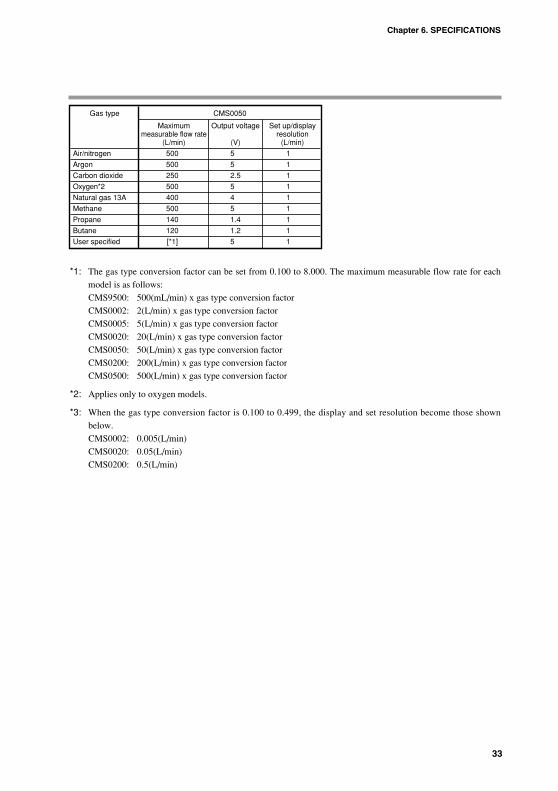
33
*1: The gas type conversion factor can be set from 0.100 to 8.000. The maximum measurable flow rate for each
model is as follows:
CMS9500: 500(mL/min) x gas type conversion factor
CMS0002: 2(L/min) x gas type conversion factor
CMS0005: 5(L/min) x gas type conversion factor
CMS0020: 20(L/min) x gas type conversion factor
CMS0050: 50(L/min) x gas type conversion factor
CMS0200: 200(L/min) x gas type conversion factor
CMS0500: 500(L/min) x gas type conversion factor
*2: Applies only to oxygen models.
*3: When the gas type conversion factor is 0.100 to 0.499, the display and set resolution become those shown
below.
CMS0002: 0.005(L/min)
CMS0020: 0.05(L/min)
CMS0200: 0.5(L/min)
Chapter 6. SPECIFICATIONS
Gas type CMS0050
Maximum Output voltage Set up/displaymeasurable flow rate resolution
(L/min) (V) (L/min)
Air/nitrogen 500 5 1
Argon 500 5 1
Carbon dioxide 250 2.5 1
Oxygen*2 500 5 1
Natural gas 13A 400 4 1
Methane 500 5 1
Propane 140 1.4 1
Butane 120 1.2 1
User specified [*1] 5 1

34
External dimensions SUS model CMS9500/0002/0005/0020/0050 Unit: mm
SUS model CMS0200 Unit: mm
X10L
L/min
EV2
EV1
ENTMODEDISP
Massflow CMS
Azbil CorporationMADE IN JAPAN
Connecting screw:2-Rc 1/2"
(90)(78)
(75)
(63)
(4.5)
98.6 18.718.7
82.1
23.2
45
(62)
50
Connector*: Hirose Electric Co., Ltd., DF11-10DP-2DS
(7.5
)
25.3
13.5
2-M4 mounting screw, depth 6
*Optional Parts (sold separately) Harness with with dedicated connector: Model No. 81446594-*** Mounting bracket: Model No. 81446721-001
48 0.3
27
0.3
Harness with dedicated connector
Mounting bracket
2-M4 screw, depth 5
X10L
L/min
EV2
EV1
ENTMODEDISP
Massflow CMS
MADE IN JAPANAzbil Corporation
37
3217
15.715.791
69.1
(7.5
) (48.
7)
18.5
(58)(75)
(48)
(58)
(4.5)
21.5
7.5
*Optional Parts (sold separately) Harness with dedicated connector: Model No. 81446594-*** Mounting bracket: Model No. 81446628-001
Connector*: Hirose Electric Co., DF11-10DP-2DS
Connecting screw: 2-Rc 1/4"
Harness with dedicated connector
Mounting bracket
Chapter 6. SPECIFICATIONS

35
SUS model CMS0500 Unit: mm
SUS316 model CMS9500/0002/0005/0020/0050 Unit: mm
MADE IN JAPANAzbil Corporation
MADE IN JAPANAzbil Corporation
X10L
L/min
EV2
EV1
ENTMODEDISP
Massflow CMS
MADE IN JAPANAzbil Corporation
MADE IN JAPANAzbil Corporation
15
0.3
37
3217
15.715.791
69.1
(7.5
) (48.
7)
18.52-9/16-18UNF
(58)(75)
(48)
(58)
(4.5)
21.5
7.5
HE
X9/
16H
EX
21
(138.8)(23.9)(23.9)
(25.7) (25.7)
(138)23.523.5 2-Rc1/4" joint
Applicable pipe: Outer dia.: 1/4" Material: SUS316
2-1/4" Swagelok jointSS-400-1-6STSC11
1/4 VCR connection type
(142.4)1/4 Swagelok connection type
Rc1/4 connection type
9/16-18 UNF connection type
2-1/4"-VCR jointSS-4-VCR-1-00032SC11
Material: SUS316
*Optional Parts (sold separately) Harness with dedicated connector: Model No. 81446594-*** Mounting bracket: Model No. 81446628-001
Connector*: Hirose ElectricCo., Ltd., DF11-10DP-2DS
2-M4 mounting screw, depth 5
48 0.3
Harness with dedicated connector
Mounting bracket
Azbil CorporationMADE IN JAPAN
X10L
L/min
EV2
EV1
ENTMODEDISP
Massflow CMS
9.3
15
29.5
59(75.
5)(8
) 6098.6
16.4 16.4
96.1
(87)
(92)
(75)
(5.5)
2-M4 mounting screw, depth 8
Connecting screw: 2-Rc 1/2"
30
0.3
80 0.3
Connector*: Hirose Electric Co., Ltd., DF11-10DP-2DS
*Optional Parts (sold separately) Harness with dedicated connector: Model No. 81446594-*** Mounting bracket: Model No. 81446856-001
(80 0.3)
Harness with dedicated connector
Mounting bracket
Chapter 6. SPECIFICATIONS

36
SUS316 model CMS0200 Unit: mm
Azbil CorporationMADE IN JAPAN
X10L
L/min
EV2
EV1
ENTMODEDISP
Massflow CMS
Azbil CorporationMADE IN JAPAN
Azbil CorporationMADE IN JAPAN
MADE IN JAPANAzbil Corporation
2-Rc1/2" joint
*Optional Parts (sold separately) Harness with dedicated connector: Model No. 81446594-*** Mounting bracket: Model No. 81446721-001
2-3/4-16 UNF
(90)(78)
(75)
(63)
(4.5)
98.6 18.718.7
82.1
23.2
45
(62)
50
(7.5
)
HE
X26
(148.6)2525
(160)(30.7) (30.7)
HE
X7/
8
25.313
.5
(161.6)(31.5)(31.5)
48 0.3
4-M4 mounting screw, depth 6
27
0.3
Connector*: Hirose Electric Co., Ltd., DF11-10DP-2DS
Applicable pipe: Outer dia.: 1/2" Material: SUS316
2-1/2" Swagelok jointSS-810-1-8STSC11
3/8" VCR connection type
1/2" Swagelok connection type
Rc1/2" connection type
3/4-16 UNF connection type
2-3/8-VCR jointSS-8-VCR-1-8STSC11 or equivalentMaterial: SUS316
Harness with dedicated connector
Mounting bracket
Chapter 6. SPECIFICATIONS

37
SUS316 model CMS0500 Unit: mm
(25) (25)
(31.5) (31.5)(161.6)
HE
X 2
6
(160)(30.7) (30.7)
(148.6)
98.616.416.4
96.1
29.5
59
(75.
5)(8
)60
9.3
(92)
(87)
15
HE
X7/
8
(80)
(75)
(5.5)
X10L
L/min
EV2
EV1
ENTMODEDISP
Massflow CMS
11
2-3/4-16 UNF
Azbil CorporationMADE IN JAPAN
Azbil CorporationMADE IN JAPAN
Azbil CorporationMADE IN JAPAN
Azbil CorporationMADE IN JAPAN 2-3/8-VCR joint
SS-8-VCR-1-8STSC11 or equivalentMaterial: SUS316
Connector*: Hirose Electric Co., Ltd., DF11-10DP-2DS
2-Rc1/2" joint
Applicable pipe: Outer dia.: 1/2" Material: SUS316
2-1/2" Swagelok jointSS-810-1-8STSC11
1/2" Swagelok connection type
3/8" VCR connection type
Rc1/2" connection type
3/4-16 UNF connection type (standard)
*Optional Parts (sold separately) Harness with dedicated connector: Model No. 81446594-*** Mounting bracket: Model No. 81446856-001
80 0.3
4-M5 mounting screw, depth 8
30
0.3
Harness with dedicated connector
Mounting bracket
Chapter 6. SPECIFICATIONS

38
Harness with dedicated connector 81446594-***
AC adapter
Note: The 81446594-030 AC adapter connection harness is necessary when supplying ACpower to the CMS.
81446594-030 AC adapter connection harness
50
-2+3
0+20
5
20
200
-2+35
2050
11
+ -
AC adapter connection
8144
6957
-001
Azb
il C
orpo
ratio
n
5026
.5
64 1800
81446594-005, -006
81446594-007, -008
Chapter 6. SPECIFICATIONS
Last 3 digits L (mm) No. ofof model No. wire
005 2000 8
006 5000 8
007 2000 10
008 5000 10
+500
+2500
+800
+2500

39
Mounting bracket, 81446628-001 (for CMS9500/0002/0005/0020/0050)Material: SUS304 Unit: mm
Mounting bracket, 81446721-001 (for CMS0200)Material: SUS304 Unit: mm
Mounting bracket, 81446856-001 (for CMS0500)Material: SUS304 Unit: mm
4-5.
5 dia
. hole
(R)
5.5
6.5
A, 4 locations
6.5
3075
80
92
13.5
60
A
13.5
(87)
5.550
12.5
12.5
2763(75)
48
7890
4.5
A
A, 4 locations
6.5
4-4.5 dia. hole
(R)
2-4.5 dia. hole
R
2-R1 o
r C1 3.2
B, 2 locations
(R)
4.5
5.5
A, 4 locations
(58)
5
48
1111
75
6.5
36 10
3.6 68
58
13.5
48
24
16.5
15 B
AMounting hole for SUS model
Mounting hole for resin model
Chapter 6. SPECIFICATIONS

40
Pressure lossThe graphs below are based on data for air. The values for gases other than air can
be obtained by multiplying by the specific gravities shown in the table below.
Example: For the CMS9500, with a primary pressure of 100 kPa and a flow rate of
500mL/min, the pressure loss for argon is calculated as follows:
From the graph for CMS9500, you know that the pressure loss is about
4.3Pa when the primary pressure is 100 kPa and the flow rate is
500mL/min.
Multiply this value by 1.38, the specific gravity of argon, and the result is
4.3 × 1.38 = 5.934 Pa.
1.0
2.0
3.0
4.0
5.0
6.0
7.0
8.0
9.0
00.0
200 400 600100 300 500
Flow rate (mL/min, standard)
Pre
ssur
e lo
ss (
Pa)
CMS9500
Chapter 6. SPECIFICATIONS
Specific gravity (with air as 1.0)
Argon 1.38
Carbon dioxide 1.53
Oxygen 1.11
Natural gas 13A 0.64
100% Methane 0.56
100% Propane 1.56
100% Butane 2.08

41
50.0
100.0
150.0
200.0
250.0
00.0
10 205 15 25
Flow rate (L/min, standard)
Pre
ssur
e lo
ss (
Pa)
CMS0020
20.0
40.0
60.0
80.0
100.0
120.0
140.0
160.0
180.0
00.0
2 4 61 3 5
Flow rate (L/min, standard)
Pre
ssur
e lo
ss (
Pa)
CMS0005
10.0
15.0
20.0
25.0
30.0
35.0
40.0
45.0
50.0
0
5.0
0.01 20.5 1.5 2.5
Flow rate (L/min, standard)
Pre
ssur
e lo
ss (
Pa)
CMS0002
Chapter 6. SPECIFICATIONS

42
Primary pressure
3kPa100kPa300kPa500kPa700kPa
500.0
1000.0
1500.0
2000.0
2500.0
00.0
200 400100 300 500 600
Flow rate (L/min, standard)
Pre
ssur
e lo
ss (
Pa)
CMS0500
Primary pressure
1kPa100kPa300kPa500kPa700kPa
200.0
300.0
400.0
500.0
600.0
700.0
800.0
0
100.0
0.0100 20050 150 250
Flow rate (L/min, standard)
Pre
ssur
e lo
ss (
Pa)
CMS0200
Primary pressure
1kPa100kPa300kPa500kPa700kPa
100.0
200.0
300.0
400.0
500.0
600.0
700.0
800.0
00.0
20 40 6010 30 50
Flow rate (L/min, standard)
Pre
ssur
e lo
ss (
Pa)
CMS0050
Chapter 6. SPECIFICATIONS

Revision History
Printed Manual Number Edition Revised pages Descriptiondate
Dec. 2006 CP-SP-1189E 1st Edition
Apr. 2012 2nd Edition Company name changed.

Specifications are subject to change without notice. (09)
1-12-2 Kawana, FujisawaKanagawa 251-8522 Japan
URL: http://www.azbil.com1st edition: Dec. 2006 (U)2nd edition: Apr. 2012 (F)