cnc programming simplifiedchapter 2 2-2 ez-cam step 4. post g-code select the “postprocessor”...
TRANSCRIPT
www.ezcam.com
EZ-Mill 2D Tutorial
CNC Programming Simplified

Copyright Notice This manual describes software that contains published and unpublished works of authorship proprietary to EZCAM Solutions, Inc. It is made available for use and maintenance of our products. Under copyright laws, this manual, or the software it describes may not be copied in whole, or in part, without prior written consent of EZCAM Solutions, Inc., except in normal software use. The information in this document is subject to change without notice and should not be construed as a commitment by EZCAM Solutions, Inc. All software package identifying names appearing herein prefaced with EZ are trademarks of EZCAM Solutions, Inc. , All Rights Reserved. EZ-CAM® and any other references to EZCAM applications software are protected by Copyright 1999-2004 of EZCAM Solutions, Inc. All Rights Reserved. Printed Documentation Copyright 1999-2004 of EZCAM Solutions, Inc. All Rights Reserved.
EZ-CAM 2-1
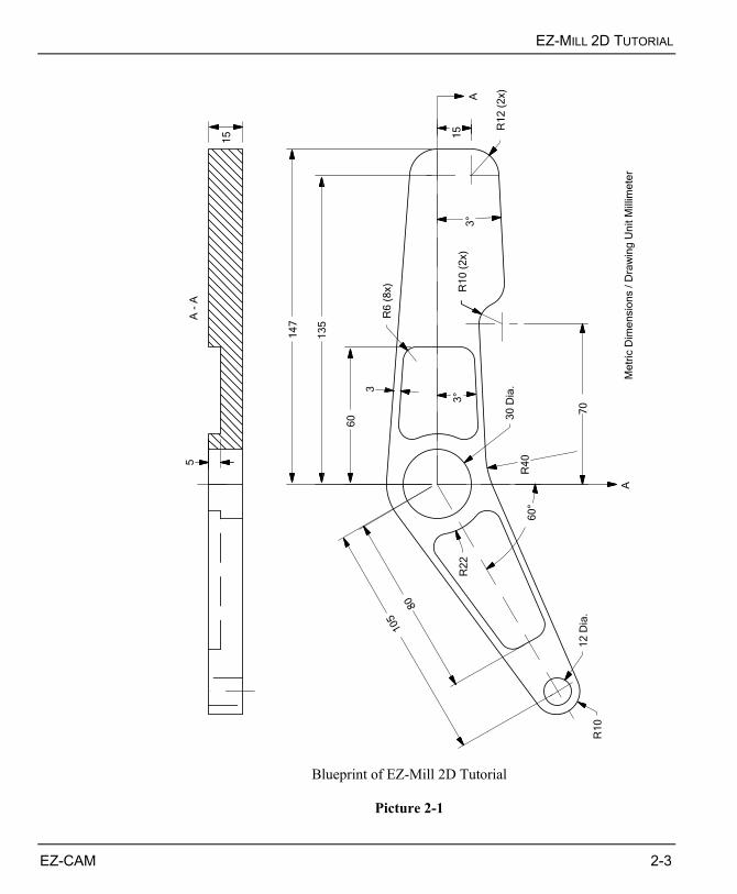
OVERVIEW This tutorial is intended for users with little, or no experience in EZ-Mill operations. The step-by-step instructions describe the complete process of creating the NC program for the 2D part shown in Picture 2-1, focusing on the machining process and also describing more advanced techniques used for roughing, finishing and Work Step handling using the integrated spreadsheet. In addition we show you how to import CAD data by loading and arranging a DXF file.
BASIC PROGRAMMING STEPS Before we continue with the tutorial let us explain the basic steps needed to create a part program with EZ-Mill. STEP 1. Create Geometry
Start by creating part geometry via commands under the Geometry Menu, or alternatively, use “File/Open” command to import geometry data from CAD sources (IGES, DXF, DWG, etc.)
STEP 2. Define Path Curves
Use the “Curves” menu commands like CHAIN, ARC, LINEAR, etc. to define curves by tracing or chaining existing geometry.
STEP 3. Create Work Steps and set Machining Parameters
Define Work Steps for each machining operation and apply the parameters as required by type of operation and tool that is used. Assign the desired path curve to each Work Step. Visualize the computed tool path to assure correct tool operation and proper setting of machining parameters.
CHAPTER 2. EZ-MILL 2D TUTORIAL

CHAPTER 2
2-2 EZ-CAM
STEP 4. Post G-Code
Select the “Postprocessor” related to the type of control and let the software create the G-Code file.
The EZ-Mill 2D Tutorial is set up in Metric with all Inputs and
Dimensions in Millimeters ! Users who want to skip the geometry creation may start with the “Import CAD Data” topic at the end of the geometry section.
EZ-MILL 2D TUTORIAL
EZ-CAM 2-3
3
°
A
A
A -
A
12
Dia
.
30
Dia
.
60
13
5
14
7
105 8
0
15
3
70
R1
2 (
2x)
R6
(8
x)
R1
0 (
2x)
R4
0
R2
2
60
°
R1
0
3
°
15
5
Me
tric
Dim
en
sio
ns /
Dra
win
g U
nit M
illim
ete
r
Blueprint of EZ-Mill 2D Tutorial
Picture 2-1

CHAPTER 2
2-4 EZ-CAM
DEFINE ORIGIN, WINDOW SIZE AND LOCATION The window size is the distance from the edge of the window to the center of the window. The window location is the signed, absolute position of the window center from the part’s origin. The viewing parameters that are found in the Setup dialog box specify the size and location of the window. Note that you would not normally perform this step in programming a part, but it is necessary here to insure clarity in following the tutorial. Normally, you would just use the Zoom/Fade commands to set the window size as needed. When selecting the origin for the part, choose a location that is referenced by the part’s dimensions. The origin should be selected before defining the window location (see next topic for setting up the workspace), because the window center is referenced from the part's origin. The graphic in Picture 2-2 below shows the location of the part origin for this exercise (X = 0, Y = 0).
Window Size
Window Center
Part Origin
20
10
X Center
Y Center
130
Picture 2-2

EZ-MILL 2D TUTORIAL
EZ-CAM 2-5
SETTING PREFERENCES Before continuing with the construction of the sample part, several parameters should be set so that the system is compatible with the instructions in this tutorial. Also the size of the workspace should be set. The sample part is about 250mm in the X-axis and 85mm in the Y-axis. Because of the size of the part, it is not convenient to work in the default window; therefore the window and some default settings have to be changed. 1. Select ”New” command from the “File” menu to restart EZ-Mill and to clear the
memory before continuing with the tutorial. Make sure that one of the EZ-Mill levels is active and press OK to start over.
The “New” dialog is also used to switch between the EZ-Mill and EZ-Turn module. Before the dialog opens, the system checks the software protection key for activated modules. Modules or levels that are not activated will be marked by appended “DEMO” text. When working in “Demo” (evaluation) mode, it is not possible to print or save data. The corresponding “Save”, “Save as” and “Print” commands are disabled. When closing the EZCAM application, the system automatically stores the last used level as default for the next session.
2. Select ”Setup” command from the “View” menu 3. Type “20” for “X Center”, “-10” for “Y Center” and “130” for “Size”.
This sets the window size from the edge of the window to the center of the window, allowing enough room to see all of the part as it is created. See Picture 2-2.

CHAPTER 2
2-6 EZ-CAM
4. Select “Metric” option button as the parts input dimension system. 5. Click the “Background” list box and select “Black”. 6. Check the box "Blank Verify" on the right. This will cause verified tool paths to be
blanked every time the view is changing or the screen is redrawn. 7. Check the box "Save as Default". The system will store all dialog settings as defaults
for future sessions. 8. After the preferences have been correctly set, click OK.
The initial setup for the EZ-MILL 2D tutorial is now complete. Continue with the next section to create the geometry necessary for this part.
EZ-MILL 2D TUTORIAL
EZ-CAM 2-7
THE PART GEOMETRY Now that the workspace has been adjusted to accommodate the part, the creation of the part can begin. This involves creating geometry that is used to define the tool paths. Before you begin check that the current view is set to X-Y.
To change system view to X-Y, click the X-Y view button. First, we will create the geometry that defines the outside contour of the sample part. Then we continue with creating the pockets. At any time you may use the Undo/Redo buttons in the upper left corner to correct any mistakes you make.
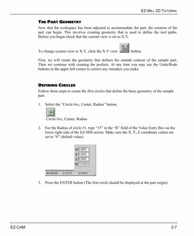
DEFINING CIRCLES Follow these steps to create the first circles that define the basic geometry of the sample part. 1. Select the “Circle/Arc, Center, Radius” button.
Circle/Arc, Center, Radius
2. For the Radius of circle #1, type “15” in the “R” field of the Value Entry Box on the
lower right side of the EZ-Mill screen. Make sure the X, Y, Z coordinate values are set to “0” (default value).
3. Press the ENTER button (The first circle should be displayed at the part origin).

CHAPTER 2
2-8 EZ-CAM
4. For the Radius of circle #2, type “22” in the “R” field of the Value Entry Box. As the
center coordinates of the second circle are same (X0/Y0), simply press the ENTER button to create the second circle.
5. For the Radius of circle #3, type “12” in the “R” field of the Value Entry Box, then
press Tab to move the focus to the “X” input field. Type “135” for the Center X location. Y position should already be set to “0”. Press the ENTER button to create third circle.
6. To create circle #4, press Tab until focus is set to the “Y” input field. Type “-15” for
the Center Y location and press the ENTER button. 7. To create circles #5 and #6 we use the “polar coordinate” input mode. Select the
“Polar Mode” option located in “Edit / Point Picking” menu. When selected you will see a small checkmark in the menu indicating the option is activated. Every selection of this menu entry toggles the polar mode “On” or “Off”.
Polar Mode
8. The content of the Value Entry Box will change as shown below. Input “210” in the
“A” field as the polar angle and “105” in the first “R” field as the polar radius to specify the center of the circle #5 by using polar coordinates. In the second “R” field input “10” for the radius of the new circle itself and press ENTER button. The polar origin is always located at the origin of the current coordinate system.

EZ-MILL 2D TUTORIAL
EZ-CAM 2-9
9. To create circle #6, change the radius value to “6” and press ENTER. Now your part
geometry should appear as in Picture 2-3. Do not forget to toggle the “Polar Mode” to “OFF” condition when finished.
Circle 1 (R15)
Circle 5 (R10)
Circle 2 (R22)Circle 6 (R6)
Circle 4 (R12)
Circle 3 (R12)Part OriginY
Z X
Picture 2-3
DEFINING TANGENTIAL LINES The next step is to define tangent lines to connect the R10, R22 and R12 circles. 1. First select the “Line , Two Points” ,then the “Tangency” button.
Line, Two Points Tangency
2. When the "Pick First Point" prompt displays in the message area, click slightly above
the R10 circle #6 (see POS #1 in Picture 2-4). 3. Then the "Pick Second Point" prompt displays. Now move the cursor to the right,
slightly above the R22 circle (see POS #2 in Picture 2-4). The geometry preview will show the next possible line. If it is OK confirm the action with a mouse- click. The new line is drawn tangent between the R10 and R22 radius circles.

CHAPTER 2
2-10 EZ-CAM
POS #1
POS #2
New Line drawn by theDynamic Preview
POS #3POS #4
POS #5
POS #6
POS #7
POS #8
Picture 2-4 4. Continue with creating lines by selecting POS #3 and POS #4 to connect the R22 and
R12 circle, POS #5 and POS #6 to connect both R12 circles, POS #7 and POS #8 to connect the R22 with the R10 circle again. See Picture 2-5 for the resulting geometry.
Y
Z X
Picture 2-5

EZ-MILL 2D TUTORIAL
EZ-CAM 2-11
CREATING LINE AT ANGLE The next step is to define a line that lies tangential to the R12 circle at an angle of 3 degrees to the X-axis. 1. Select the “Line at Angle” button.
Line at Angle
2. Click the X-axis coordinate system handle with the mouse to define the reference
axis for the angle.
Y
XZCursor Position toselect X Axis
3. Type “3” in the “A” field of the Value Entry Box (Do not press ENTER). 4. Select the “Tangency” button.
Tangency
5. Move the cursor to a position slightly below the R12 circle as shown in Picture 2-6.
The geometry preview will show the new line. If it is OK confirm the action with a mouse click.
Cursor Position to selecttangent Point on Circle
New Line drawn by theDynamic Preview
Y
Z X
Picture 2-6

CHAPTER 2
2-12 EZ-CAM
REMOVING LINE SEGMENTS Follow the instructions below to remove some of the line segments. 1. Click the “Remove to Closest” button. This command will allow you to remove a
segment of a line, arc, or circle between the closest boundaries.
Remove to Closest
2. At the "Pick Line, Arc or Circle" prompt, select the line segments to be removed as
shown in Picture 2-7. The result should appear as in Picture 2-8.
Cursor Positions to removeLine Segments
Y
Z X
Picture 2-7
Y
Z X
Picture 2-8
EZ-MILL 2D TUTORIAL
EZ-CAM 2-13
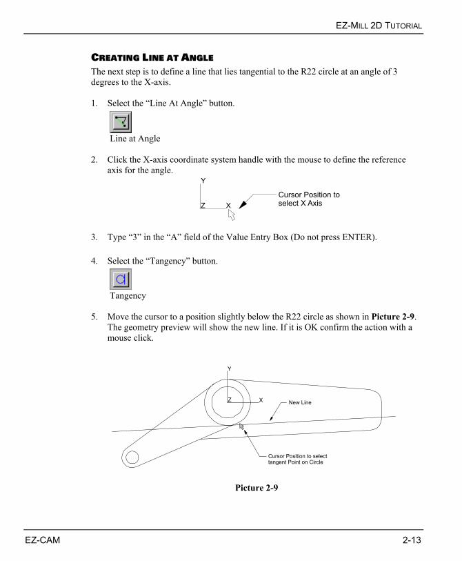
CREATING LINE AT ANGLE The next step is to define a line that lies tangential to the R22 circle at an angle of 3 degrees to the X-axis. 1. Select the “Line At Angle” button.
Line at Angle
2. Click the X-axis coordinate system handle with the mouse to define the reference
axis for the angle.
Y
XZCursor Position toselect X Axis
3. Type “3” in the “A” field of the Value Entry Box (Do not press ENTER). 4. Select the “Tangency” button.
Tangency
5. Move the cursor to a position slightly below the R22 circle as shown in Picture 2-9.
The geometry preview will show the new line. If it is OK confirm the action with a mouse click.
Y
Z X
Cursor Position to selecttangent Point on Circle
New Line
Picture 2-9

CHAPTER 2
2-14 EZ-CAM
CREATING A CORNER FILLET Now we're going to create a corner fillet between two lines meeting below the R22 radius circle. 1. Click the “Corner Fillet” button.
Corner Fillet
2. When the Value Entry Box prompts for a radius value, type “40” in the “R” field. 3. At the "Pick int. of two lines, arcs or circles" prompt, move the cursor to the inside of
the intersection between the two lines as shown in Picture 2-10. Pausing the mouse over the corner without clicking, the dynamic preview will show the fillet to be inserted. Clicking there will actually insert the fillet.
Y
Z X
Cursor Position to selectCorner Fillet Position
Picture 2-10

EZ-MILL 2D TUTORIAL
EZ-CAM 2-15
DEFINING PARALLEL LINES Now we will create some help geometry to find the center of the R10 circle 70mm to the right of the part origin. First we define a line that lies parallel to the Y-axis at a distance of 70mm. Then we create a line with a distance of 10mm to the 3° angled line starting at the R40 corner fillet in the lower part of the geometry. 1. First select the “Line , Parallel” button.
Line, Parallel
2. For the parallel distance type “70” in the “D” field of the Value Entry Box.
(Do not press ENTER). 3. Move the cursor to the right side of the systems Y-axis coordinate handle as shown in
Picture 2-11. The geometry preview will show you a line parallel to the Y-axis with a distance of 70mm. If the preview is OK confirm with a mouse click.
Y
Z X
New Parallel Line
70
Cursor Position
Picture 2-11

CHAPTER 2
2-16 EZ-CAM
4. For the second parallel line type “10” in the “D” field of the Value Entry Box.
(Do not press ENTER). 5. Move the cursor to a position below the 3° line as shown in Picture 2-12. The
geometry preview will show you the new parallel line with a distance of 10mm to the selected line. If the preview is OK confirm with a mouse click.
Y
Z X
Cursor Position
New Parallel Line
10
Picture 2-12

EZ-MILL 2D TUTORIAL
EZ-CAM 2-17
DEFINING CIRCLE Next step is to define the R10 circle at the intersection of the newly created parallel lines (help-geometry) by specifying its radius and center location. 1. Select the “Circle/Arc, Center, Radius” button and the “Snap All” pick mode.
Circle/Arc, Center, Radius Snap All
2. For the Radius type “10” in the “R” field of the Value Entry Box. 3. Move the cursor to the intersection of the two parallel lines like shown in Picture 2-
13. The geometry preview will show you a circle moving on the screen along with your mouse cursor. When the software snaps to the correct position and the preview is OK confirm with a mouse click to create the circle.
Y
Z X
Cursor Position
New R10 Circle
Picture 2-13
CHAPTER 2
2-18 EZ-CAM
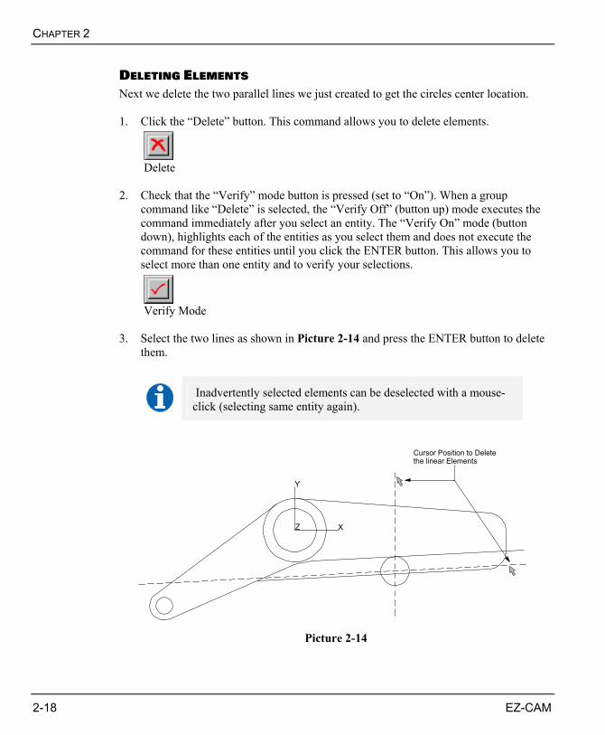
DELETING ELEMENTS Next we delete the two parallel lines we just created to get the circles center location. 1. Click the “Delete” button. This command allows you to delete elements.
Delete
2. Check that the “Verify” mode button is pressed (set to “On”). When a group
command like “Delete” is selected, the “Verify Off” (button up) mode executes the command immediately after you select an entity. The “Verify On” mode (button down), highlights each of the entities as you select them and does not execute the command for these entities until you click the ENTER button. This allows you to select more than one entity and to verify your selections.
Verify Mode
3. Select the two lines as shown in Picture 2-14 and press the ENTER button to delete
them.
Inadvertently selected elements can be deselected with a mouse-click (selecting same entity again).
Y
Z X
Cursor Position to Deletethe linear Elements
Picture 2-14

EZ-MILL 2D TUTORIAL
EZ-CAM 2-19
DEFINING TANGENTIAL ARC Follow these steps to create the R10 arc that fills the corner of the existing R10 circle and the angled line. This is accomplished by specifying the radius and two points that lie tangential on both elements. For the result see Picture 2-15. 1. Select the “Circle/Arc, Two Points, Radius” button.
Circle/Arc, Two Points, Radius
2. Select the “Finite Mode“ option located in “Geometry” menu. For all Circle/Arc
commands, “Finite Mode” OFF creates circles, ON creates arcs. When selected you will see a small checkmark in the menu indicating the option is activated. Every selection of this menu entry toggles the finite mode “On” or “Off”. ! Do not forget to “uncheck” this option after the arc has been created !
3. For the Radius type “10” in the “R” field of the Value Entry Box. 4. Select the “Tangency” button.
Tangency
5. Move the cursor to the right side of the existing R10 circle as shown in Picture 2-15
and click the mouse. The circle will be displayed in dotted style after being selected. Now move the cursor to a position slightly above the angled line. The geometry preview will show the new arc when moving the cursor to this position. Confirm the action with a mouse click. See Picture 2-15 for the result.

CHAPTER 2
2-20 EZ-CAM
Y
Z X
Cursor Positions to create tangent R10 Circle
Picture 2-15
REMOVING LINE/ARC SEGMENTS Follow the instructions below to remove some parts of the geometry to clean up and finish the outside profile of the part. 1. Click the “Remove to Closest” button. This command will allow you to remove a
segment of a line, arc, or circle between the closest boundaries.
Remove to Closest
2. At the "Pick Line, Arc or Circle" prompt, select the line and arc segments to be
removed until the result appears as in Picture 2-16.
Y
Z X
Picture 2-16

EZ-MILL 2D TUTORIAL
EZ-CAM 2-21
DEFINING PARALLEL LINES Now we continue with creating the pocket on the right side. First we need two parallel lines with a distance of 3mm to the existing angled lines. In addition we also need a line offset 60mm to the right of the Y-axis. 1. First select the “Line Parallel” button.
Line, Parallel
2. For the distance type “3” in the “D” field of the Value Entry Box.
(Do not press ENTER). 3. Move the cursor to the POS #1 slightly above the angled line as shown in Picture 2-
17. The geometry preview will show you a parallel line at a distance of 3mm. If the preview is OK confirm with a mouse click. Repeat the same at POS #2.
4. Now type “60” in the “D” field of the Value Entry Box (Do not press ENTER). 5. Move the cursor to the right side of the systems Y-axis coordinate handle as shown in
Picture 2-17. The geometry preview will show you a line parallel to the Y-axis with a distance of 60mm offset to the right side. Confirm with a mouse click if the preview is OK.
Y
Z X
60
3
3
New Parallel Lines
POS #1
POS #2
POS #3
Picture 2-17

CHAPTER 2
2-22 EZ-CAM
CREATING CORNER FILLETS IN POCKET Now we're going to create corner fillets inside the right pocket. 1. Click the “Corner Fillet” button.
Corner Fillet
2. When the Value Entry Box prompts for a radius value, type “6” in the “R” field. 3. At the "Pick int. of two lines, arcs or circles" prompt, move the mouse to the four
positions shown in Picture 2-18. The dynamic preview will show the fillet to be inserted. Clicking there will actually insert the fillet.
Y
Z X
Cursor Positions to insert Corner Fillets
Picture 2-18
EZ-MILL 2D TUTORIAL
EZ-CAM 2-23
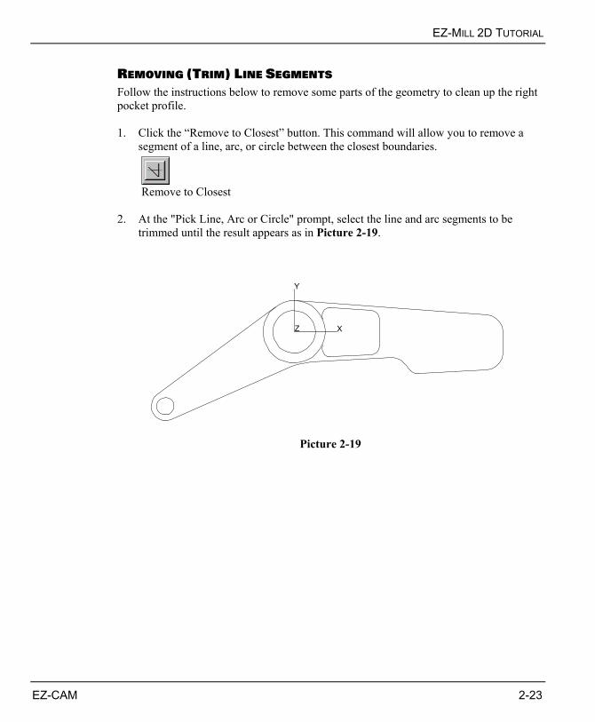
REMOVING (TRIM) LINE SEGMENTS Follow the instructions below to remove some parts of the geometry to clean up the right pocket profile. 1. Click the “Remove to Closest” button. This command will allow you to remove a
segment of a line, arc, or circle between the closest boundaries.
Remove to Closest
2. At the "Pick Line, Arc or Circle" prompt, select the line and arc segments to be
trimmed until the result appears as in Picture 2-19.
Y
Z X
Picture 2-19
CHAPTER 2
2-24 EZ-CAM
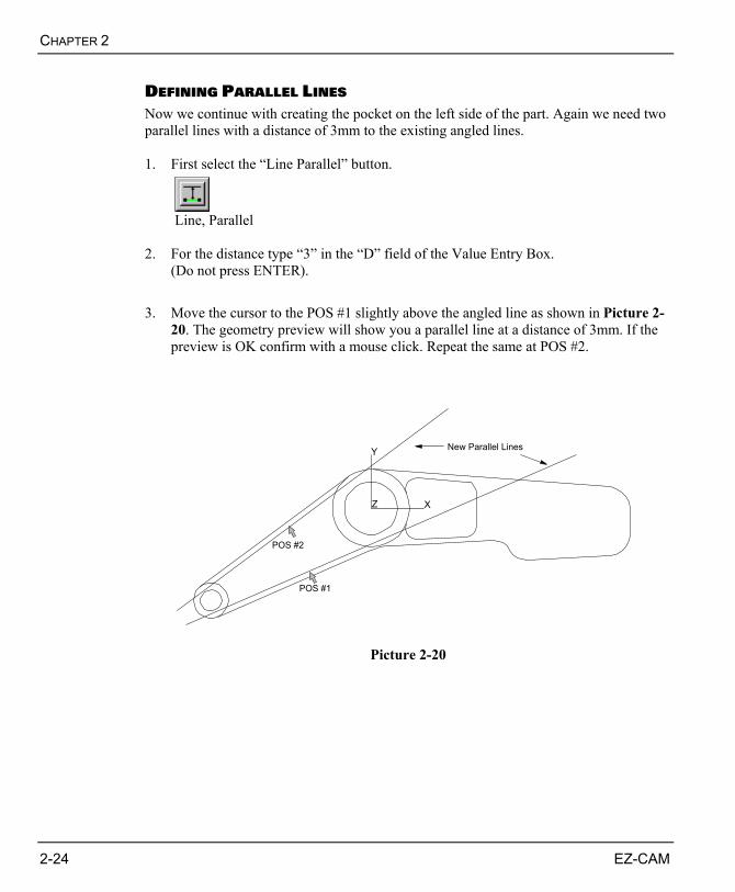
DEFINING PARALLEL LINES Now we continue with creating the pocket on the left side of the part. Again we need two parallel lines with a distance of 3mm to the existing angled lines. 1. First select the “Line Parallel” button.
Line, Parallel
2. For the distance type “3” in the “D” field of the Value Entry Box.
(Do not press ENTER). 3. Move the cursor to the POS #1 slightly above the angled line as shown in Picture 2-
20. The geometry preview will show you a parallel line at a distance of 3mm. If the preview is OK confirm with a mouse click. Repeat the same at POS #2.
Y
Z X
New Parallel Lines
POS #1
POS #2
Picture 2-20
EZ-MILL 2D TUTORIAL
EZ-CAM 2-25
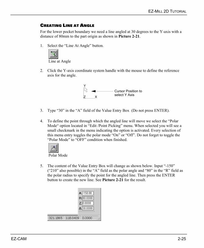
CREATING LINE AT ANGLE For the lower pocket boundary we need a line angled at 30 degrees to the Y-axis with a distance of 80mm to the part origin as shown in Picture 2-21. 1. Select the “Line At Angle” button.
Line at Angle
2. Click the Y-axis coordinate system handle with the mouse to define the reference
axis for the angle.
Y
XZ
Cursor Position toselect Y Axis
3. Type “30” in the “A” field of the Value Entry Box (Do not press ENTER). 4. To define the point through which the angled line will move we select the “Polar
Mode“ option located in “Edit /Point Picking” menu. When selected you will see a small checkmark in the menu indicating the option is activated. Every selection of this menu entry toggles the polar mode “On” or “Off”. Do not forget to toggle the “Polar Mode” to “OFF” condition when finished.
Polar Mode
5. The content of the Value Entry Box will change as shown below. Input “-150”
(“210” also possible) in the “A” field as the polar angle and “80” in the “R” field as the polar radius to specify the point for the angled line. Then press the ENTER button to create the new line. See Picture 2-21 for the result.

CHAPTER 2
2-26 EZ-CAM
Y
Z X
150°
80
New Line
Point defined by Polar Coordinates
30°
Picture 2-21
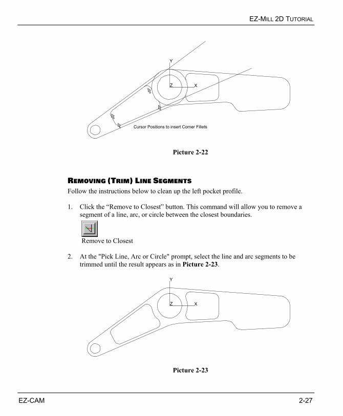
CREATING CORNER FILLETS IN POCKET Now we're going to create the corner fillets inside the left pocket. 1. Click the “Corner Fillet” button.
Corner Fillet
2. When the Value Entry Box prompts for a radius value, type “6” in the “R” field. 3. At the "Pick int. of two lines, arcs or circles" prompt, move the mouse to the
positions shown in Picture 2-22. The dynamic preview will show the fillet to be inserted. Clicking there will actually insert the fillet.
EZ-MILL 2D TUTORIAL
EZ-CAM 2-27
Y
Z X
Cursor Positions to insert Corner Fillets
Picture 2-22
REMOVING (TRIM) LINE SEGMENTS Follow the instructions below to clean up the left pocket profile. 1. Click the “Remove to Closest” button. This command will allow you to remove a
segment of a line, arc, or circle between the closest boundaries.
Remove to Closest
2. At the "Pick Line, Arc or Circle" prompt, select the line and arc segments to be
trimmed until the result appears as in Picture 2-23.
Y
Z X
Picture 2-23
CHAPTER 2
2-28 EZ-CAM
The following two topics explain how to import and move geometry from a CAD source by loading a DXF file. If you have already created the geometry by following the previous topics please jump to the “Creating the Boundary Rectangle” topic to add the frame needed as the pocket boundary for roughing the outside profile.
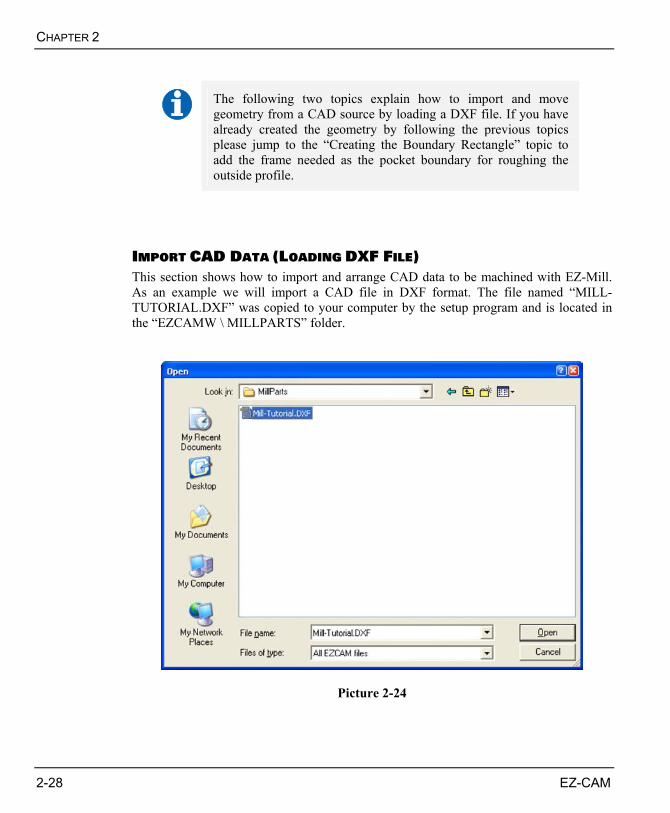
IMPORT CAD DATA (LOADING DXF FILE) This section shows how to import and arrange CAD data to be machined with EZ-Mill. As an example we will import a CAD file in DXF format. The file named “MILL-TUTORIAL.DXF” was copied to your computer by the setup program and is located in the “EZCAMW \ MILLPARTS” folder.
Picture 2-24
EZ-MILL 2D TUTORIAL
EZ-CAM 2-29
1. Select “Open” command from the “File” menu to open the file dialog. In Picture 2-
24 you can see the dialog displayed on a Windows XP professional workstation system. This dialog may vary according to the version of the Windows operating system running on your machine.
2. Select the folder “EZCAMW \ MILLPARTS” on the drive where you installed the
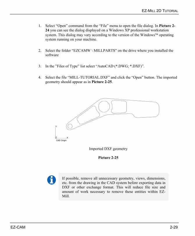
software 3. In the ”Files of Type” list select “AutoCAD (*.DWG; *.DXF)”. 4. Select the file “MILL-TUTORIAL.DXF” and click the “Open” button. The imported
geometry should appear as in Picture 2-25.
Y
Z XCAD Origin
Imported DXF geometry
Picture 2-25
If possible, remove all unnecessary geometry, views, dimensions, etc. from the drawing in the CAD system before exporting data in DXF or other exchange format. This will reduce file size and amount of work necessary to remove these entities within EZ-Mill.
CHAPTER 2
2-30 EZ-CAM
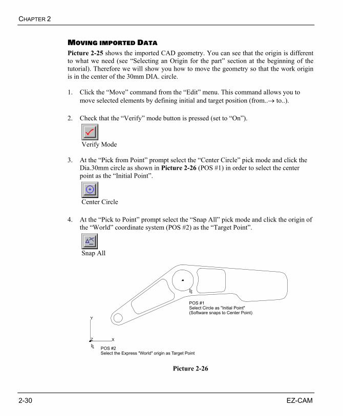
MOVING IMPORTED DATA Picture 2-25 shows the imported CAD geometry. You can see that the origin is different to what we need (see “Selecting an Origin for the part” section at the beginning of the tutorial). Therefore we will show you how to move the geometry so that the work origin is in the center of the 30mm DIA. circle. 1. Click the “Move” command from the “Edit” menu. This command allows you to
move selected elements by defining initial and target position (from..→ to..). 2. Check that the “Verify” mode button is pressed (set to “On”).
Verify Mode
3. At the “Pick from Point” prompt select the “Center Circle” pick mode and click the
Dia.30mm circle as shown in Picture 2-26 (POS #1) in order to select the center point as the “Initial Point”.
Center Circle
4. At the “Pick to Point” prompt select the “Snap All” pick mode and click the origin of
the “World” coordinate system (POS #2) as the “Target Point”.
Snap All
Y
Z X
POS #1Select Circle as "Initial Point"(Software snaps to Center Point)
POS #2Select the Express "World" origin as Target Point
Picture 2-26
EZ-MILL 2D TUTORIAL
EZ-CAM 2-31
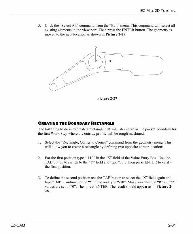
5. Click the “Select All” command from the “Edit” menu. This command will select all
existing elements in the view port. Then press the ENTER button. The geometry is moved to the new location as shown in Picture 2-27.
Y
Z X
Picture 2-27
CREATING THE BOUNDARY RECTANGLE The last thing to do is to create a rectangle that will later serve as the pocket boundary for the first Work Step where the outside profile will be rough machined. 1. Select the “Rectangle, Corner to Corner” command from the geometry menu. This
will allow you to create a rectangle by defining two opposite corner locations. 2. For the first position type “-110” in the “X” field of the Value Entry Box. Use the
TAB button to switch to the “Y” field and type “30”. Then press ENTER to verify the first position.
3. To define the second position use the TAB button to select the “X” field again and
type “160”. Continue to the “Y” field and type “-70”. Make sure that the “R” and “Z” values are set to “0”. Then press ENTER. The result should appear as in Picture 2-28.

CHAPTER 2
2-32 EZ-CAM
Y
Z X
POS #1[ X-110.0 / Y30.0 ]
POS #2[ X160.0 / Y-70.0 ]
Picture 2-28
If you want to save the newly created geometry before continuing, jump to the “Save Part Program” section at the end of the tutorial.
EZ-MILL 2D TUTORIAL
EZ-CAM 2-33
THE PATH CURVES Before we continue with the path curve creation we will give you a short explanation about what a path curve is. Each Work Step needs a profile or shape the tool follows in some way. Therefore a path (curve) has to be assigned to every Work Step following certain rules determined by the selected machining cycle (Contour, Pocket, Drilling, etc.). For example it is allowed to define an open path when using the “Contour” feature, whereas a “Pocket” path always has to be closed. As any path is represented by curves within EZ-CAM it is important to know that the software makes use of the curve entity in several different ways. It can be used as a simple tool path for contouring, as a machining boundary to define a pocket or an island, or it may be used to define a surface (Mill / Mill-Pro levels only). All of these uses for the curve make it a very flexible and powerful feature. For example you can create multiple Work Step’s to machine the same curve for roughing and finishing or Spot-Drilling with subsequent Drilling operations. A curve can be a straight line, an arc, a spline, or a combination of these things. It may include "rapid" moves, or it may be a single point. The curve does not have to follow any specific rules on its own, but as mentioned above, certain rules determined by the desired operation and the selected machining cycle have to be followed. For this tutorial we have to create 5 Curve entities:
1. Boundary curve (rectangle) representing the outside boundary when roughing the part (leaving 0.2mm stock allowance for finishing).
2. Contour curve for the parts outside shape 3. Pocket curve 1 for the circular pocket 4. Pocket curve 2 including the left and right side pockets 5. Drilling curve representing the 12mm DIA hole position
You will have to assign a unique ID to each curve that is created. Use your own ID’s or the systems default (Crv1, Crv2, etc.). When working on extensive projects it is always good to use ID’s that can be easily remembered and that reflect the purpose of the curve. Important ! Don’t use space or any other special characters in the curve ID.

CHAPTER 2
2-34 EZ-CAM
POCKET PATH CREATION RULES This tutorial uses “Pocket” and “Zig-Zag” cycles for roughing of the outside and inside pocket profiles. Below you find a list of the most important rules to be followed when creating curves to be used in conjunction with one of these cycles. • “Pocket” and “Zig-Zag” cycles always need a closed boundary curve (same start &
endpoint). • The boundary may start with a rapid move to define the plunge location. • No rapid move within the boundary profile itself is allowed. • If a pocket contains any islands, there are two ways to define these:
Include boundary and islands in one single curve. The islands are directly appended to the boundary curve by rapid moves. Boundary and all island profiles have to be closed shapes. The element sequence of a curve including boundary and 2 islands follows.
Boundary Profile -> Rapid Move -> Island1 -> Rapid Move -> Island 2
Create separate curves for boundary and islands. When creating the Work Step
later, select the boundary curve in the “Path ID” list box and all islands in the “Check Curves” table. The result will be the same as mentioned before but the advantage is that there is no need to define different curves for rough and finishing operations.
The tutorial will make use of the second method creating separate curves for boundary and island profiles.
• A circular boundary or island must contain at least three points (two arc elements).
See the EZ-Mill Help for more information about “Pocket“ paths.

EZ-MILL 2D TUTORIAL
EZ-CAM 2-35
CREATING THE BOUNDARY CURVE For the first rough machining operation we need a curve that represents the pocket boundary. We will use the existing geometry rectangle to define the curve. 1. First we have to create a new curve. Therefore select the “New” command from the
“Curves” menu or click the corresponding button. In the dialog that opens type “Boundary” as the new ID and confirm with OK.
New
2. To define the boundary profile we use the “Chain” option. Select the “Chain”
command from the “Curves” menu or click the corresponding button.
Chain
3. The prompt “Select First Line or Arc” is displayed at the bottom edge of the window.
Move the cursor to Position as shown in Picture 2-29 and double-click the mouse to select the line as the first element in the curve chain. The software automatically completes the curve by following the connecting geometry elements from the first point to the last.
Y
Z X
Cursor Position to select first boundaryelement to be "Chained"
Picture 2-29
CHAPTER 2
2-36 EZ-CAM
The position where the first element is selected is very important to the direction of
the curve. The items between the selected elements are automatically completed by the software and displayed as shown in Picture 2-30. A small arrow referred to as the “direction indicator” shows the path direction.
Y
Z X
Completed "Boundary" Curve
Picture 2-30
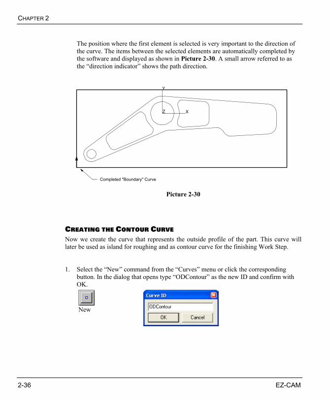
CREATING THE CONTOUR CURVE Now we create the curve that represents the outside profile of the part. This curve will later be used as island for roughing and as contour curve for the finishing Work Step. 1. Select the “New” command from the “Curves” menu or click the corresponding
button. In the dialog that opens type “ODContour” as the new ID and confirm with OK.
New

EZ-MILL 2D TUTORIAL
EZ-CAM 2-37
2. Select “Chain” from the “Curve” menu or click the corresponding button. Move the
cursor to Position as shown in Picture 2-31 and double-click the arc near by its start point to select this entity as the first element in the curve chain. The software automatically completes the curve resulting in a clockwise direction as shown in Picture 2-32.
Chain
Y
Z X
Cursor Position to select the Arc asthe first Element of the "ODContour" Curve
Picture 2-31
Y
Z X
Completed "ODContour" Curve
Picture 2-32

CHAPTER 2
2-38 EZ-CAM
CREATING THE POCKET1 CURVE Next comes the creation of the curve representing the circular pocket. 1. Select the “New” command from the “Curves” menu or click the corresponding
button. In the dialog that opens type “Pocket1” as the new ID and confirm with OK.
New
2. Select “Chain” from the “Curve” menu or click the corresponding button. Move the
cursor to Position as shown in Picture 2-33 and double-click the arc. The software automatically creates a circular curve in counter-clockwise direction with the start at the 0 degree position. The result is shown in Picture 2-34.
Chain
Y
Z X
Double Click at Cursor Position to selectCircle for "Pocket1" Curve
Picture 2-33

EZ-MILL 2D TUTORIAL
EZ-CAM 2-39
Y
Z X
Completed "Pocket1" Curve
Picture 2-34

CHAPTER 2
2-40 EZ-CAM
CREATING THE POCKET2 CURVE Since the remaining two pocket profiles will later be machined using the same tool, technology and machining parameters, we will combine these two shapes into one single curve. The connection is achieved by a rapid link that is inserted automatically by the software when the “Chain” command is used multiple times on independent profiles. You will also learn how to control the start/end point of the curve as well as the curve direction. This is very important because both chained profiles need to have the same direction if combined into one single curve. 1. Select the “New” command from the “Curves” menu or click the corresponding
button. In the dialog that opens type “Pocket2” as the new ID and confirm with OK.
New
2. Select “Chain” from the “Curve” menu or click the corresponding button. Then move
the cursor to the “Pocket A” profile and double-click anywhere along this contour (see Picture 2-35). Do the same anywhere along the “Pocket B” contour. The system automatically chains all elements and connects both pocket profiles using a rapid move represented by a dotted line between the start points of each of the two profiles. Don’t worry about correct start point and curve direction, as we will take care of that in the next step.
Chain
Y
Z X
Double-click once anywhere along each of the pocket profilesto chain the Geometry Elements for "Pocket2" Curve
Pocket A
Pocket B
Picture 2-35

EZ-MILL 2D TUTORIAL
EZ-CAM 2-41
3. In the following step we are going to define the start/end point for both profiles in the
“Pocket2” curve. First select “Start/End” from the “Curve” menu, then switch to the “Midpoint” pick mode from the “Edit/Point Picking” menu. If you now move the cursor along the existing “Pocket2” curve profiles the dynamic preview automatically snaps to the next possible midpoint that can be selected. Click at positions #1 on “Pocket A” and #2 on “Pocket B” as shown in Picture 2-36. Make sure to click on the inside of the profiles. See Picture 2-36/2 for the result.
Start/End Pick Midpoint
Y
Z X
Cursor Positions inside Pocket Profilesto select new Start Point Locations
Pocket A
Pocket B#1
#2
Picture 2-36
Y
Z X
Rapid Move connecting both Pocket Paths
Start Pocket A
Start Pocket B
Picture 2-36/2

CHAPTER 2
2-42 EZ-CAM
The Start/ End curve command is only applicable to existing curves that represent closed profiles. It actually combines several important tasks into one single command. 1. Move the Start/End point of existing curve In combination with one of the available “Pick” modes it is possible to select any point (endpoint, midpoint, etc) along the existing curve profile as the new start/end location. 2. Specify Curve direction If the cursor is positioned inside the closed profile then the curve direction is automatically set to counter-clockwise. If outside then direction is clockwise. If necessary this can later be changed by using the “Reverse Direction” command from the “Curves” menu. 3. Insert Rapid Move (Plunge Point Location) If the specified start/end location is not lying on the curve itself the system will insert a perpendicular rapid move connecting the selected position with the profile. This is later used as plunge position by the “Zig-Zag” and “Pocketing” cycles.

EZ-MILL 2D TUTORIAL
EZ-CAM 2-43
CREATING THE 12MM HOLE CURVE Finally the last curve to be created defines the 12mm DIA hole position. 1. Select the “New” command from the “Curves” menu or click the corresponding
button. In the dialog that opens type “Drill12” as the new ID and confirm with OK.
New
2. To create the path click the “Linear” button or select the command in the “Curve”
menu.
Linear
3. Next select the “Center Circle” pick mode and move the cursor to the position as
shown in Picture 2-37 in order to define the center coordinates. The geometry preview will help you as it automatically snaps to the center when moving the cursor on the existing circle. Click the mouse to select the position. The finished path is displayed in form of a small triangle as shown in Picture 2-38.
Center Arc / Circle
Y
Z X
Cursor Position to select Drilling Location
Picture 2-37

CHAPTER 2
2-44 EZ-CAM
Y
Z X
Completed "Drill12" Curve
Picture 2-38

EZ-MILL 2D TUTORIAL
EZ-CAM 2-45
CREATING THE PART PROGRAM Now as the curves for the sample part are created we continue with the definition of the Work Steps that are necessary to machine the part. Every Work Step is created by selecting a cycle (Contour, Pocket, Drilling, etc.), specifying associated tool settings / machining parameters and assigning a curve that will be machined. Verifying the calculated tool path assures correct tool operation. Finally, when all necessary Work Steps have been defined the complete part program can again be visually checked using the 3D solid simulation. If everything works fine you can continue to the next step and create the CNC-Code.
Execution of the Work Steps will be in the same order they have been created. You can use the integrated spreadsheet to perform operations such as moving, reordering or deleting existing Work Steps. See the “Spreadsheet” book in the online help for more detailed information.
The Part Program section of the EZ-Mill tutorial contains all Work Steps that are necessary to machine the part. The part program of the tutorial will consist of these 8 Work Steps: 1. Zig-Zag “Face” machining to rough machine the outside profile leaving 0.2mm
stock allowance for finishing. 2. “Pocket” machining of curve “Pocket1”leaving 0.2mm stock allowance for finishing. 3. “Pocket” machining of curve “Pocket2” leaving 0.2mm stock allowance for
finishing. 4. Finishing (“Contouring”) the outside profile 5. Finishing (“Contouring”) Pocket1 (circular pocket) 6. Finishing (“Contouring”) Pocket2 7. Spot-Drill 12mm DIA hole 8. Drill 12mm DIA hole
CHAPTER 2
2-46 EZ-CAM
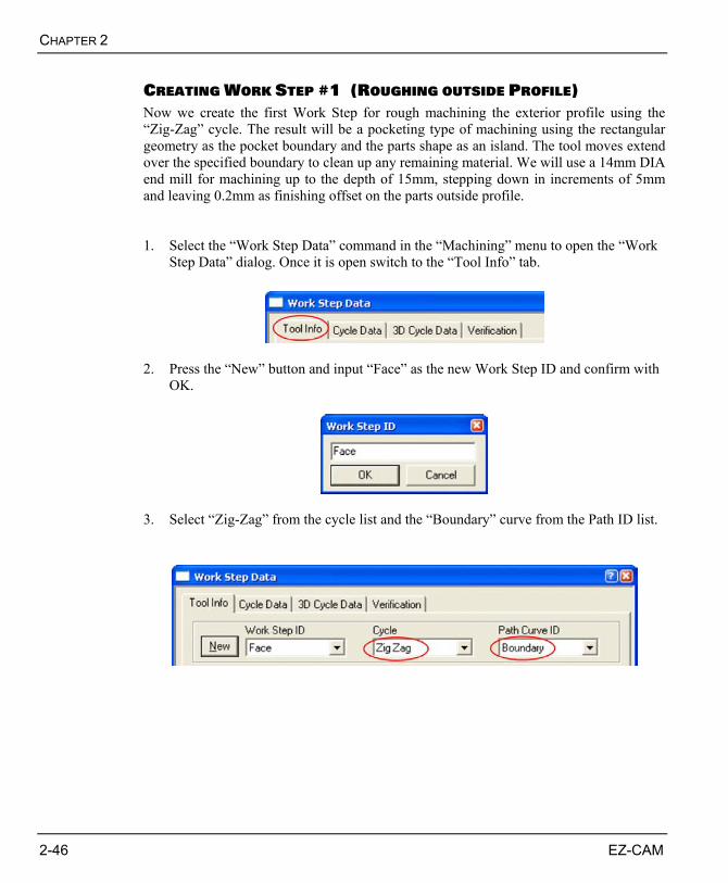
CREATING WORK STEP #1 (ROUGHING OUTSIDE PROFILE) Now we create the first Work Step for rough machining the exterior profile using the “Zig-Zag” cycle. The result will be a pocketing type of machining using the rectangular geometry as the pocket boundary and the parts shape as an island. The tool moves extend over the specified boundary to clean up any remaining material. We will use a 14mm DIA end mill for machining up to the depth of 15mm, stepping down in increments of 5mm and leaving 0.2mm as finishing offset on the parts outside profile. 1. Select the “Work Step Data” command in the “Machining” menu to open the “Work
Step Data” dialog. Once it is open switch to the “Tool Info” tab.
2. Press the “New” button and input “Face” as the new Work Step ID and confirm with
OK.
3. Select “Zig-Zag” from the cycle list and the “Boundary” curve from the Path ID list.

EZ-MILL 2D TUTORIAL
EZ-CAM 2-47
4. Input tool and technology settings to the appropriate fields as shown in Picture 2-39.
Picture 2-39 5. Select the “Cycle Data” tab and make sure that the “Finish Pass”, “Face Milling”,
“Minimize Jumps” and “Climb Milling” options are checked. . Input “0.2” to the “Stock Allow” field. This will result in 0.2 mm of material left on the contour to be removed later by the finishing Work Step. Input “5” as “Step Over” value for the “Zig-Zag” cycle. See Picture 2-40.

CHAPTER 2
2-48 EZ-CAM
Picture 2-40 6. By the previous selection of the “Boundary” curve in the “Path ID” list, we only
specified the outer border for the “Zig-Zag” cycle. As already mentioned one way to define islands is to directly append them at the end of the boundary curve. For this tutorial we will apply the second method by putting the “ODContour” curve to the “Check Curves” list. Therefore select the “3D Cycle Data” tab and press the “Add” button in the “Check Curves” section. On the dialog that opens select the “ODContour” curve from the list and continue pressing the “Add” button. Also note the “Fin Allow” automatically set to the same value as “Stock Allow” from the previous “Cycle Data” tab. Finally close the Work Step Data dialog using the “Close” button. See Picture 2-41.

EZ-MILL 2D TUTORIAL
EZ-CAM 2-49
Picture 2-41 7. To ensure that the first Work Step was created correctly, it must be verified. Switch
to “X-Y View” using the command button. Then click the “Verify” button. The system calculates the cutter path as shown in Picture 2-42.
X-Y View Verify
Picture 2-42
The first Work Step is now complete. Hit the “Redraw” button to refresh the screen and remove the verified tool path display.
CHAPTER 2
2-50 EZ-CAM
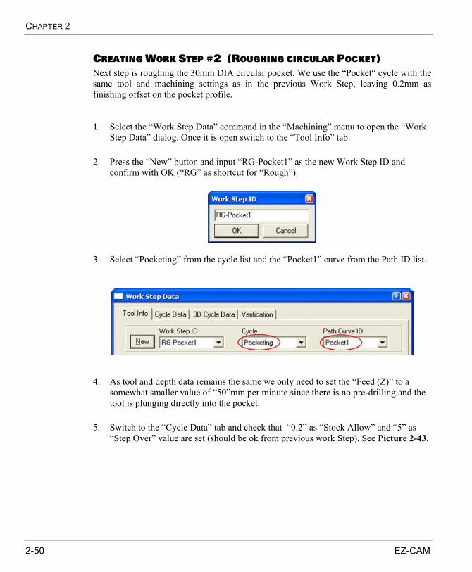
CREATING WORK STEP #2 (ROUGHING CIRCULAR POCKET) Next step is roughing the 30mm DIA circular pocket. We use the “Pocket“ cycle with the same tool and machining settings as in the previous Work Step, leaving 0.2mm as finishing offset on the pocket profile. 1. Select the “Work Step Data” command in the “Machining” menu to open the “Work
Step Data” dialog. Once it is open switch to the “Tool Info” tab. 2. Press the “New” button and input “RG-Pocket1” as the new Work Step ID and
confirm with OK (“RG” as shortcut for “Rough”).
3. Select “Pocketing” from the cycle list and the “Pocket1” curve from the Path ID list.
4. As tool and depth data remains the same we only need to set the “Feed (Z)” to a
somewhat smaller value of “50”mm per minute since there is no pre-drilling and the tool is plunging directly into the pocket.
5. Switch to the “Cycle Data” tab and check that “0.2” as “Stock Allow” and “5” as
“Step Over” value are set (should be ok from previous work Step). See Picture 2-43.

EZ-MILL 2D TUTORIAL
EZ-CAM 2-51
Picture 2-43 6. For Verification click the “Verify” button. The system calculates the tool path. Then
you may use the “Simulate Tool” command to get a more realistic simulation of the tool movement as shown in Picture 2-44.
Verify Simulate Tool
Y
Z X
Picture 2-44
The second Work Step is now complete. Hit the “Redraw” button to refresh the screen and remove the verified tool path display.

CHAPTER 2
2-52 EZ-CAM
CREATING WORK STEP #3 (ROUGHING INSIDE POCKETS) Next step is roughing the two inside pockets. We use the “Pocketing“ cycle with a 10mm DIA end mill to machine the pockets up to the depth of 5mm in one step leaving 0.2mm as finishing offset on the pocket profile. Both pocket boundaries have already been defined in the same curve reducing input and Work Step management because they are machined using identical parameters and settings. 1. Select the “Work Step Data” command in the “Machining” menu to open the “Work
Step Data” dialog. Once it is open switch to the “Tool Info” tab. 2. Press the “New” button and input “RG-Pocket2” as the new Work Step ID and
confirm with OK.
3. Select “Pocketing” from the cycle list and the “Pocket2” curve from the Path ID list.
4. Input new tool and technology settings in the appropriate fields as shown in Picture
2-45.

EZ-MILL 2D TUTORIAL
EZ-CAM 2-53
Picture 2-45 5. Switch to the “Cycle Data” tab and check that “0.2” as “Stock Allow” and “5” as
“Step Over” value are set (should be ok from previous work Step). 6. For Verification click the “Verify” button. The system calculates the tool path. Then
use the “Simulate Tool” command to get a more realistic simulation of the tool movement as shown in Picture 2-46.
Verify Simulate Tool
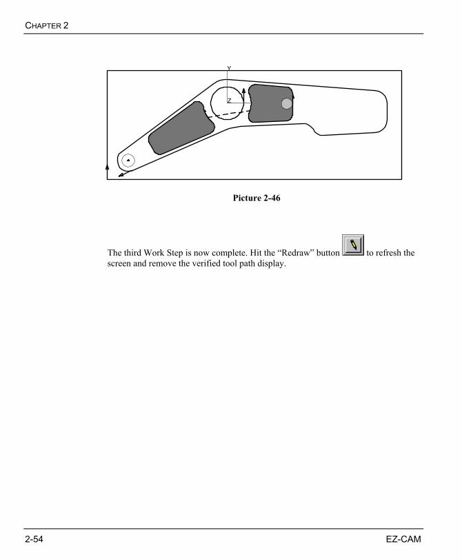
CHAPTER 2
2-54 EZ-CAM
Y
Z X
Picture 2-46
The third Work Step is now complete. Hit the “Redraw” button to refresh the screen and remove the verified tool path display.

EZ-MILL 2D TUTORIAL
EZ-CAM 2-55
CREATING WORK STEP #4 (FINISHING OUTSIDE PROFILE) This Work Step will finish the outside profile in clockwise direction using a 10mm DIA end mill. We also use the automatic Ramp/Lead options that will calculate Ramp and Lead moves at beginning and end of the profile. 1. Select the “Work Step Data” command in the “Machining” menu to open the “Work
Step Data” dialog. Once it is open switch to the “Tool Info” tab. 2. Press the “New” button and input “FN-Outside” as the new Work Step ID and
confirm with OK.
3. Select “Contouring” from the cycle list and the “ODContour” curve from the Path ID
list.
4. Input following tool and technology settings in the appropriate fields located in the
“Tool Info” tab.
Tool Number : 3 Diameter (Top) : 10 Spindle RPM : 1500 Feed (X-Y) : 300 Feed (Z) : 250 ZDepth : 15 Zstep : 0

CHAPTER 2
2-56 EZ-CAM
5. Select the “Cycle Data” tab and input new cycle specific settings as shown in Picture 2-47. This includes the correct “Offset Dir” set to left, “Stock Allow” now “0” and combined Ramp and Lead options.
Picture 2-47 6. For Verification click the “Verify” button. The system calculates the tool path. Then
use the “Simulate Tool” command to get a realistic simulation of the tool movement. See Picture 2-48.
Verify Simulate Tool

EZ-MILL 2D TUTORIAL
EZ-CAM 2-57
Y
Z X
Y
Z X
Picture 2-48
The Work Step #4 is now complete. Hit the “Redraw” button to refresh the screen and remove the verified tool path display.
If the verified tool path is on the wrong side of the profile open the “Work Step Data” dialog. Select the “Cycle Data” tab and make sure that the “Work Step ID” list shows the name of the Work Step you are currently working on. Check that the “Offset Dir” parameter is set to “Left”. If that is already the case, then the path was chained in counter clockwise direction. To change path direction click the “Reverse Dir” checkbox on the same page. Be aware that the “Reverse Dir” option only reverses the calculated tool path without touching the original curve. As an alternative you may select the “Reverse Direction” command located in the “Curves” menu. This command reverses the direction of the current curve.
CHAPTER 2
2-58 EZ-CAM
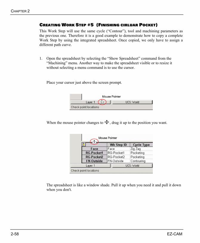
CREATING WORK STEP #5 (FINISHING CIRLUAR POCKET) This Work Step will use the same cycle (“Contour”), tool and machining parameters as the previous one. Therefore it is a good example to demonstrate how to copy a complete Work Step by using the integrated spreadsheet. Once copied, we only have to assign a different path curve. 1. Open the spreadsheet by selecting the “Show Spreadsheet” command from the
“Machining” menu. Another way to make the spreadsheet visible or to resize it without selecting a menu command is to use the cursor. Place your cursor just above the screen prompt.
When the mouse pointer changes to , drag it up to the position you want.
The spreadsheet is like a window shade. Pull it up when you need it and pull it down when you don't.
EZ-MILL 2D TUTORIAL
EZ-CAM 2-59
2. To select the complete Work Step to be copied, click the cursor in the first cell as
shown in Picture 2-49.
Picture 2-49 3. The next step is to copy the Work Step to the clipboard. You can activate the
spreadsheet menu by selecting the yellow arrow or right-click on the mouse. Either way, once you have activated the menu, select the “Copy Work Step” command. See Picture 2-50.
Picture 2-50

CHAPTER 2
2-60 EZ-CAM
4. Now that Work Step “FN-Outside” has been copied to the clipboard, the next step is
to select the position where you want the Work Step to be pasted back into the spreadsheet. Remember, the “Paste Work Step” command always inserts the Work Step above the active cell or row in the spreadsheet. As we want the copied Work Step to be inserted at the end, click anywhere within the “Total” row to make this the active row. See Picture 2-51.
Picture 2-51 5. Activate the spreadsheet menu by clicking the yellow arrow or by right-clicking the
mouse. Click on the “Paste Work Step” command as shown in Picture 2-52. Picture 2-53 shows the copied Work Step named “2xFN-Outside”, “2x” indicating that it was copied from “FN-Outside”.
Picture 2-52

EZ-MILL 2D TUTORIAL
EZ-CAM 2-61
Picture 2-53
A similar method is used to reorder Work Steps. The only difference is to use the “Cut Work Step” command instead of “Copy Work Step”. This will remove the Work Step from the spreadsheet and copy the data to the Clipboard. Then select the position where you want the Work Step to be pasted back and select the “Paste Work Step” command.
6. As can be seen in Picture 2-53 the Work Step ID is automatically named “2xFN-
Outside”. To rename the Work Step directly select the “Wk Step ID” field with the cursor, type the new name “FN-Pocket1” and press ENTER button. For the result see Picture 2-54.
Picture 2-54
CHAPTER 2
2-62 EZ-CAM
7. As we copied the whole Work Step there is still the “ODContour” curve associated to
the new copy. To assign the correct pocket curve use the cursor to select the corresponding field in the “Path ID” column. Select the “Pocket1” curve from the list that opens when pressing the small arrow button. See Picture 2-55.
Picture 2-55 8. For Verification click the “Verify” button. The system calculates the tool path. Use
the “Simulate Tool” command to get a realistic simulation of the tool movement. See Picture 2-56.
Verify Simulate Tool
Y
Z X
Picture 2-56
The Work Step #5 is now complete. Hit the “Redraw” button to refresh the screen and remove the verified tool path display.
EZ-MILL 2D TUTORIAL
EZ-CAM 2-63
CREATING WORK STEP #6 (FINISHING INSIDE POCKETS) This Work Step finishes the two remaining pockets up to the depth of 5mm. Like we did in the previous step we will use the spreadsheet to copy and paste “FN-Pocket1” Work Step to save time, as most of the tool parameters and settings for the new Work Step will be identical. For a more detailed explanation on how to copy and paste Work Step’s in the spreadsheet see the previous Topic (Work Step #5). 1. Open the spreadsheet by selecting the “Show Spreadsheet” command from the
“Machining” menu or use the cursor. 2. Select “FN-Pocket1” as the Work Step to be copied. Right-click to open the menu
and click the “Copy Work Step” command. 3. Click somewhere in the “Total” line because the “Paste Work Step” command
always pastes the Work Step above the active cell or row in the spreadsheet. Right-click to open the menu and click the “Paste Work Step” command. Picture 2-57 shows the copied Work Step named “2xFN-Pocket1”.
Picture 2-57 4. As in the previous Work Step we will also rename the ID of the copied Work Step.
Therefore select the “Wk Step ID” field with the cursor and type the new name “FN-Pocket2” and press ENTER button.

CHAPTER 2
2-64 EZ-CAM
5. To change the depth setting of the new Work Step select the appropriate cell in the
“ZDepth” column with the mouse and input “5” as the new depth. See Picture 2-58.
Picture 2-58 6. To change the already assigned path curve use the cursor to select the corresponding
field in the “Path ID” column. Select the “Pocket2” curve from the list that opens when pressing the small arrow button. See Picture 2-59.
Picture 2-59 8. For Verification click the “Verify” button. The system calculates the tool path. Use
the “Simulate Tool” command to get a more realistic simulation of the tool movement as shown in Picture 2-61.
Verify Simulate Tool
EZ-MILL 2D TUTORIAL
EZ-CAM 2-65
Y
Z X
Picture 2-61
The Work Step #6 is now complete. Hit the “Redraw” button to refresh the screen and remove the verified tool path display.

CHAPTER 2
2-66 EZ-CAM
CREATING WORK STEP #7 (SPOT-DRILLING 12MM HOLE) After completion of the milling operations we continue with spot-drilling the12mm DIA hole using the standard “Drilling“ cycle 1. Select the “Work Step Data” command in the “Machining” menu to open the “Work
Step Data” dialog. Once it is open switch to the “Tool Info” tab. 2. Press the “New” button and input “Spot-Dia12” as the new Work Step ID and
confirm with OK.
3. Select “Drill” from the cycle list and the “Drill12” curve from the Path ID list.
4. Input following tool and technology settings in the appropriate fields located in the
“Tool Info” tab.
Tool Number : 4 Diameter (Top) : 10 Spindle RPM : 1600 Feed (Z) : 120 ZDepth : 3
EZ-MILL 2D TUTORIAL
EZ-CAM 2-67
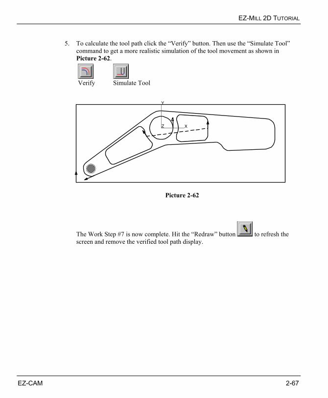
5. To calculate the tool path click the “Verify” button. Then use the “Simulate Tool”
command to get a more realistic simulation of the tool movement as shown in Picture 2-62.
Verify Simulate Tool
Y
Z X
Picture 2-62
The Work Step #7 is now complete. Hit the “Redraw” button to refresh the screen and remove the verified tool path display.

CHAPTER 2
2-68 EZ-CAM
CREATING WORK STEP #8 (DRILLING 12MM HOLE) This Work Step finishes the part by drilling the 12mm DIA hole. We will copy and paste the existing “Spot-Dia12” Work Step and edit cycle, tool and machining parameters using the spreadsheet. There is no need to assign a different path curve since it is the same as the one that was already copied from the “Spot-Dia12” Work Step. 1. Open the spreadsheet by selecting the “Show Spreadsheet” command from the
“Work Step” menu or use the cursor. 2. Select “Spot-Dia12” as the Work Step to be copied. Right-click to open the menu and
click the “Copy Work Step” command. 3. Click somewhere in the “Total” line because the “Paste Work Step” command
always pastes the Work Step above the active cell or row in the spreadsheet. Right-click to open the menu and click the “Paste Work Step” command. Picture 2-63 shows the copied Work Step named “2xHoles1”.
Picture 2-63 4. As in the previous Work Step we will also rename the ID of the copied Work Step.
Therefore select the “Wk Step ID” field with the cursor and type the new name “Drill-Dia12” and press ENTER button. Move the cursor to the Cycle Type” field and select the “Chip Break” cycle. See Picture 2-64.

EZ-MILL 2D TUTORIAL
EZ-CAM 2-69
Picture 2-64 5. Use the arrow keys to navigate through the cells of the “Drill-Dia12” Work
Step and assign the settings listed below. The result should appear as in Picture 2-65.
Tool Number : 5 Diameter (“Dia”) : 12 Spindle Speed (RPM) : 1200 Feed Rate (“Fd Z”) : 80 Depth (“ZDepth”) : 21 Step (“ZStep”) : 3
Picture 2-65

CHAPTER 2
2-70 EZ-CAM
6. To calculate the tool path click the “Verify” button. Then use the “Simulate Tool”
command to get a more realistic simulation of the tool movement as shown in Picture 2-66.
Verify Simulate Tool
Y
Z X
Picture 2-66
The Work Step #8 is now complete. Hit the “Redraw” button to refresh the screen and remove the verified tool path display.

EZ-MILL 2D TUTORIAL
EZ-CAM 2-71
ESTIMATING TOTAL MACHINING TIME The “Verify All” command in the “Post” menu is used to estimate the total machining time. It performs an on-screen verification of all Work Steps in memory, in the machining order. The total machining time (not including rapid traverse or tool change time) is displayed in a dialog box at the end of the verification process. To close the dialog click OK. To get the same view as shown in Picture 2-67, switch to isometric using the “View Isometric” command and select “Verify All” to start tool path calculation.
View Isometric
Verify All
Picture 2-67
It is very important for the “3D Preview” simulation in the next section to have toolpaths of all work steps verified completely. If you previously interrupted any computation during “Verify” by hitting “Escape”, or have started a new session and loaded your previously saved work, you must first “Verify All” work steps.

CHAPTER 2
2-72 EZ-CAM
3D SOLID PREVIEW One of the most powerful EZ-CAM features is the 3D solid preview function. This function shows an animated tool cutting a solid model of the programmed part. Once the simulation is finished or interrupted by the user pressing “Esc” key, all dynamic view commands to rotate, zoom or move the simulated model on the screen are available. If no “Stock Setup” has been defined when the “Preview 3D” command is called, the system automatically calculates the “Stock” size, according to the maximum calculated tool movements. For the tutorial we will manually assign the stock size using the “Stock Setup” dialog that can be opened from the “Machining” menu. 1. Select the “Stock Setup” command from the “Machining” menu and input the values
as shown in Picture 2-68. Close the dialog with OK.
Picture 2-68

EZ-MILL 2D TUTORIAL
EZ-CAM 2-73
2. Before starting the preview select the “Isometric View” command. Then start the
simulation using “Preview 3D” command from the “Machining” menu or the corresponding button. See Picture 2-69.
View Isometric
Preview 3D
Picture 2-69 3. Once the simulation stopped you can change the on-screen view by using the
dynamic view commands (Rotate, Pan, Zoom) from the “View / Dynamic Viewing” menu.
Dynamic Rotate Dynamic Zoom Dynamic Pan

CHAPTER 2
2-74 EZ-CAM
SAVING THE PART It is very important to save the newly created or edited part from memory to disk periodically during a session as well as at the end to ensure that no information is lost. The EZ-CAM “Save” and “Save as” commands under the File menu transfer files from system memory to a hard disk or other media. In EZ-MILL, the part information is stored in two different types of files, the “Part” file using the extension "3DP" and the associated “Geometry” file with extension "GEO". This flexibility allows the user to load an existing part file to be used with newly created geometry and path curves. File Type : GEOMETRY Extension : GEO Data : Geometry Elements (lines, arcs, etc.), Curves,
User Coordinate Systems (UCS) File Type : PART Files Extension : 3DP Data : Work Step Data (Technology & Machining Information) There is no specific rule what should be saved first. Of course, if there is only one kind of data in memory (Work Steps or Geometry) the “Save as” dialog will automatically be set to the correct file type.
Picture 2-70

EZ-MILL 2D TUTORIAL
EZ-CAM 2-75
1. Select “Save as” command from the “File” menu. 2. Select the appropriate drive and folder where the geometry and part files should be
stored. You can use the “EZCAMW \ MILLPARTS” folder that was automatically created by the setup routine.
3. Select “Geometry (*.GEO)” from the “Save as type” list box to store the geometry
data. 4. Type the new filename “Mill-Tutorial” in the File Name box and click the “Save”
button. The file extension is added automatically. 5. To store the machining information (Work Step Data) select “Part Files (*.3DP)”
from the “Save as type” list box and click “Save” again.
If you have already saved the geometry, the software automatically inserts a part file with the same name but different extension (*.3DP) in the “Save” menu when the first Work Step is created. All you have to do is to select “Save All” option from the “File” menu or the corresponding toolbar button.
Save All
The software will save and overwrite the existing files without any screen prompt. You can use this command anytime for fast saving of your work.

CHAPTER 2
2-76 EZ-CAM
It is not possible to save data when the software is running in evaluation mode. The “Save”, “Save as” and “Print” commands are disabled.
CREATING CNC CODE Now that the part program has been created, it must be converted to run on a NC control by running the “Post” command with the appropriate “Post-Processor” for your machine.
The CNC data file or “Post-Processor” is used as a "template" to format the part program data file that was created in EZ-Mill. This template consists of program formats (e.g., TOOL CHANGE, LINEAR MOVE, RAPID MOVE, etc.) that determine the structure of a part program for a specific CNC. To create or edit a “Post-Processor” a special editor called “MBuild” is required.
1. Select “Post” command in the “Machining” menu to open the “Post Process” dialog.
Picture 2-71
EZ-MILL 2D TUTORIAL
EZ-CAM 2-77
2. First you need to select the postprocessor. If the one desired is already loaded and
displayed in the section “CNC-File”, continue to the next step. Otherwise use the “Change” button to browse your system for a different one. For this tutorial you may use the “FAN-DEMO.CNC” post (standard metric post that creates Fanuc style code).
Standard postprocessor folders created by the EZ-CAM v14 setup: INCH <DRIVE>: \ EZCAMW \ EZCAM14 \ MILLINCHPOST METRIC <DRIVE>: \ EZCAMW \ EZCAM14 \ MILLMETRICPOST
3. Select the “G-Code” option from the “Listings” list box. The computed program text
will be displayed on the screen. 4. Activate (check) the “EZ-DNC” option. This will automatically start the “EZ-DNC”
application when posting of the part file is finished and load the newly created file for sending it to the machine using the serial port. See Chapter 6 “Communication with the Control” for more information about EZ-DNC.
5. Next is the “G-Code File” section. Here the default name and directory for the
computed program file is displayed. The name is taken from the part file that was saved before. The default directory is “EZCAMW\MILLGCODE”.
Ensure that part file and postprocessor share the same dimension unit (“Metric” for this tutorial). The system will generate a “Dimension Unit Conflict” message, but then automatically scale the NC-Code according to the dimension specified in the postprocessor. See online help for more information about the “Setup” dialog located in the “View” menu.
6. Click the “Post” to start posting. The Processing window will be displayed showing
messages followed by listings of ASCII code created. When all Work Steps have been processed, a final message dialog box is shown. See Picture 2-72.

CHAPTER 2
2-78 EZ-CAM
Picture 2-72 7. Click OK to close the message dialog box. To close the Processing window
click at the top right-hand corner of the window.
Congratulations!
You've completed the EZ-MILL 2D Tutorial !