cnc routers selecting the right tool, maximizing machine
TRANSCRIPT

For more information or to place an order call Edge Of Arlington at 817-461-7171 Page 1
Edge of Arlington Saw & Tool Inc 124 S. Collins St.
Arlington, TX 76010
817-461-7171 Metro
888-461-7171 Toll Free
817-795-6651 Fax
CNC ROUTERS
Selecting the right tool, maximizing
machine time, finish, tool life & profits.
I am a torque wrench –
use me
I am a collet – I am inexpensive but critical
and need to be replaced every 400 to 600
hours or when damaged.

For more information or to place an order call Edge Of Arlington at 817-461-7171 Page 2
Table of Contents
Topic Pages
Introduction 3
Factors to consider before selecting a tool 3-4
The many factors affecting tool life and finish quality. 4 -6
Collets & Tool Holders 6-7
Tightening Stands & Torque specifications 8-9
Torque Wrenches & Accessories 9-10
Taper Wipers 10
Spoil Boards, Hold-Downs & Dust Collection 11-13
Techniks Aggregate Heads 13-14
Climb VS. Conventional cut 15
Tool Materials 15-16
Tool Geometry 16-19
Chipload 20-21
Feed & Speed 21-22
Things to Avoid 22-23
Index 24-25

For more information or to place an order call Edge Of Arlington at 817-461-7171 Page 3
The following are general guidelines for profitably operating CNC routers when machining wood,
plastic, composites and other man-made materials. There are many factors to consider and the choices can
sometimes seem overwhelming. The purpose of this manual is to familiarize you with some basic principles
that will enable you to adapt to any cutting situation.
Friction during the cutting process results in enormous heat generation. In metalworking, you may
consult a machinist manual and find out exactly what tool to use and how fast to run it; the heat can be
removed through the use of flood coolants and lubricants. The heat produced when cutting materials such as
wood or plastic isn’t handled quite as easily. This is perhaps the most important concept for you to
understand; heat is you enemy, it dulls tools and fatigues metal. When cutting wood, plastics, etc you control
heat through tool geometry, dust collection and manipulating the chipload.1
Each routing situation is different and adjustments should be made in order to achieve the desired
goal. It is a continuing trial, error and improvement process. Through proper set-up, machine maintenance,
tool selection and manipulating the feed (rate of travel) and speed (RPM of the spindle) you can keep cost low
while maintaining quality and production.
When cutting through 3/4”material at rates in excess of 1000 inches per minute (IPM) you are moving
a lot of material quickly. Take a minute and think about what you are asking this machine to do. Most of the
time you are using a tool that is only ¼” to ½” in diameter. The spindle rates are up to 24,000 RPM. If
everything is not in perfect harmony you are setting yourself up for failure.
Many factors need to be considered when evaluating any cutting situation and before
selecting a tool:
What is the desired finish? Chip free, hidden part, some minor chips ok, etc. Are both sides (top, bottom) of material of equal importance? The desired finish will often dictate not only what type of tool we can use but also how fast we can cut and whether or not we have to make multiple passes.
Which is more important, speed or finish? While striving for both, sometimes we must assign priorities or make compromises. Higher quality finish can mean higher machining costs (multiple passes, use of more expensive tooling, slower feed rates, etc.) but; ironically, most people run their tools at too slow a feed rate at too high of a RPM; resulting in heat build-up and premature tool wear.
What are the machines capabilities and limitations? It is important to know your CNC’s capabilities and limitations. If your machines top feed speed is 600 IPM as opposed to a machine capable of feed speeds of 1200 IPM, your tool selection and set-up will be very different. It is important to note here that just because your machine is capable of running at 3400 IPM does not mean you can cut at that rate. When programming any cut for the first time it is important to ascertain at what feed that part is actually being cut at; part size or geometry alone may preclude you from running more than a few hundred IPM.
1 In the simplest terms, chipload refers to the size of the chip produced during the cutting process. Assuming a 1 flute tool, the
chipload would be equal to the distance of travel during 1 revolution of the spindle. See sections on chipload and feed & speed.

For more information or to place an order call Edge Of Arlington at 817-461-7171 Page 4
Do you have sufficient ability to hold the material you are cutting? If you can't hold it, you can't cut it. This is one of the most common problems that I encounter. I am continually amazed how many people will accept minimal feed rates and quality because of chatter and movement. Your ability to make a clean fast cut is related to your ability to hold the material firmly without vibration. Insufficient hold down can be responsible for everything from premature tool wear and breakage to sub-standard parts, chatter marks, chipping and material movement. A little planning and effort will give you huge payoffs in productivity and cost savings. When purchasing a CNC router; don’t skimp on the vacuum system, I have never met anyone who said they had too much.
What is the material you are cutting? Raw particle board, plywood, MDF, single-sided laminate, double-sided laminate etc. Different materials have different cutting properties and may restrict your tool selection and will often dictate geometries, feed, speed, etc.
Are there any operations after this one that will cover, conceal or change the shape of the part being cut? For example: the top edge will be rounded over or the edge will be covered in such a manner so that a small chip would be of no importance.
Is exact size important? Does another part rely on the accuracy of this part? Maintaining exacting measurements may require multiple passes after a tool is serviced or if the size is non-standard. Edge of Arlington offers Insert and diamond tooling designed to solve these types of problems.
Part configuration and size are important considerations. Small parts can be hard to hold. Intricate parts, parts with holes, curves and short cuts can be challenging due to heat generated because of machinery’s inability to make instantaneous speed and directional changes. Advances in machine capabilities have greatly improved the speeds associated with travel time and the ability to change direction etc. However, a bit turning at 18,000 RPM still turns at 3oo Inches per second and a good Boy Scout can start a camp fire with a stick at a much lower RPM.
In order to maximize quality and production time, it is important to understand how the many factors that affect tool life and finish work together:
Programming – Good programming techniques can make all the difference. Programmers must be familiar with their machine, material, software, tooling, capabilities, limitations and idiosyncrasies if true optimization is to be achieved. They must also be in close contact with the machine operator and open to feedback. By the use of entrance and exit ramps, feed and speed variations, directional changes, selection of tool path, etc. the programmer is able to compensate for machine limitations and utilize machine capabilities to their fullest. Software and machinery manufacturers are continually upgrading and addressing some of these issues as technology advances; however, there is no substitute for hands-on experience and trial and error. Programmers should not be afraid to experiment and should always document their successes and failures.
Operator – A well trained, experienced, observant operator can be invaluable. The operator must be in close contact with the programmer if quality and efficiency are to be achieved. The operator is the last line of defense; they should be instructed in the safe operation of the machine, to report problems such as heat build-up, burning, part movement, chatter, and inappropriate tool wear and maintenance issues. They must have the proper tools to allow them to do their job – tightening stands, torque wrenches, well maintained machines, and access to information. This is an area where many people try to skimp. They spend $100,000’s on machinery but won’t spend $300 for a torque wrench, $30 for a collet or a few hours training for the operator. They want to make it an “idiot proof”, minimum wage,

For more information or to place an order call Edge Of Arlington at 817-461-7171 Page 5
automated job – not a practical solution unless you wish to micro-manage and are prepared to pay the high costs associated with premature tool and machine wear and tear.
Vibration - Vibration is a major source of tool wear and poor finish quality. Factors affecting vibration include: how securely the material is being held, the type, thickness and rigidity of material being cut, collet condition, collet torque, spindle bearings, machine condition and chipload.
Machinery - horsepower, rigidity, run-out, spindle condition, clamping system, etc. A well maintained machine includes the vacuum and dust collection systems also. Preventive maintenance is a necessity in order to maintain quality finished parts; avoid major, expensive repairs and maximize machine time, tool life and profits. Your machinery dealer can be a valuable partner when it comes to machinery selection, questions and issues.
Collet – Your router bit is only as good as the collet it is in. This inexpensive, wearable part is often overlooked and can lead to poor finish, premature tool wear, tool breakage and unnecessary machine wear and tear. The collet must be in pristine condition and under the proper torque in order to align the bit perfectly on center – ALWAYS USE A TORQUE WRENCH. The torque wrench should be used for tightening only, using for loosening can lead to miss-calibration. A tool with run-out will cause inconsistent chipload, causing finish degradation, heat buildup and tool damage. Collets should be kept clean and replaced regularly and never over tightened. An improperly colleted bit can cut the tool life in half or more.
Heat - Heat build-up is the biggest cause of tool wear and breakage. Coolants are not practical for most CNC operations involving wood or composites. However, the use of air cooling and the air flow from dust collection can significantly reduce heat and extend tool life. In woodworking and plastics, heat is controlled by manipulation of the chip and dust collection. Adjust the feed and speed in order to achieve the biggest chipload possible; while producing the desired finish. The chip takes the heat from the tool; the heat dulls the tool. Never leave a tool in the cut longer than necessary, heat will build very rapidly. Heat is a function of surface footage per unit of time, the denser the material, the faster the feed rate needed to minimize heat build-up.
Dust collection- This system removes the chip from the cutting surface; the chip takes the heat with it. The importance of a good vacuum system cannot be overstated. If waste material is not removed from the cut, the chips may be repeatedly pulled into the cutting circle. This can cause the cutting life of the tool to be reduced by as much as 50% and the finish may take on a glazed or burnished appearance. The flow of air over the spindle and tool also helps to keep the bit cool. If dust collection is not working at top efficiency the heat can quickly damage the edges of the tool. Dust can also become a health and safety issue, dust control is a major problem in most manufacturing situations. Up-shear spirals can aid in chip removal but put upward pressure on the material.
Tool sharpness - As a tool dulls the edges begin to "pit". In carbide tooling this is caused more from heat and chemicals in the materials being cut than from the actual cutting process. Tools should be changed at the first sign of deterioration. Using a tool for too long can cause finish degradation of the product, tool damage or breakage. Cutting that “one last part” may result in an excessive “dull line” or damage; you may not be able to sharpen the tool or sharpening may be limited as it becomes necessary to grind off more of the carbide in order to restore the cutting edge.
Tool type – High speed steel (HSS), carbide-tipped (CT), solid carbide (SC), diamond (PCD), etc. The type of material being cut will often limit if not dictate what type of tool to use. HSS works well on soft material; PCD is very wear resistant but is very brittle and expensive. For a more detailed discussion read the section on tool types.

For more information or to place an order call Edge Of Arlington at 817-461-7171 Page 6
Tool geometry - Different materials require different hook angles, relief angles, clearance angles etc. It is important that these angles be maintained when the tool is sharpened. When a tool is serviced the dimensions will change; most often the diameter and clearance angles will become smaller. Adjustments in feed rates and tool off-sets may be necessary after a tool has been serviced.
Feed & Speed - These two factors go hand and hand. When adjusting one you must always consider the other. The feed and speed should be adjusted in such a way that there is a constant and even pressure during cutting. Too fast a feed rate given hold-downs and other factors will cause strain and deflection of the bit (run-out). Too slow a feed rate will cause friction and burning. At the proper feed and speed the router bit will be at or near room temperature; never touch a tool when it is turning! For a more detailed discussion see the sections on chip load and on feed & speeds.
Material being cut - Most man-made materials are hard on tooling, they can contain everything from chemicals and glue to sand and metal. All of these are sources of tool wear and breakage. Even natural woods have chemicals, knots, different grain directions and foreign matter. The properties of the material to be cut will dictate what type of geometry will give you the best finish. Also, the thicker the material, the longer the tool, and therefore the greater chance of run-out and deflection.
Laminates - Laminates are made for looks, strength and scratch resistance. The same processes that make them scratch resistant, also makes them harder and more costly to machine. Laminates can be extremely dense and can contain practically anything. They are notorious for dulling tools quickly and for chipping or fraying on the edge. Often times a router bit may be chipping the laminate but the rest of the tool will be sharp; oscillating the bit up and down during the cutting process is one way that machinery manufacturers and software companies are trying to combat these type problems. Controlling heat through proper feed, speed and tool selection is the key when cutting laminates.
Drilling – Most of the newer machines have drilling heads utilizing the European style boring tools. These tools generally are 57mm or 70mm long and have a 10mm shank with a flat and set screw in the bottom of the shank for minor height adjustments. The boring heads work off a gear system and therefore alternate right hand (RH) and left hand (LH) rotation. The bits and heads are usually color coded – black for RH rotation, red or orange for LH rotation. They are available in brad point (BP) for general purpose, thru-hole (TH) for use when going all the way through the material, and hinge style for larger holes. You may also use the router for drilling but you must be able to turn the RPM down to very low RPM’s (2500 or less) in order to really control the heat and chip. In either case, the use of router bits to drill will result in excessive heat and should be used only when there is no other option. You will dull a router bit more drilling one hole than cutting out the entire part. The CNC router has evolved to be the new workhorse for the 21ST century. In the last 20 years or so the
CNC router has replaced the table saw, panel saw and hand held router as the tool of choice, one router and a
good operator can produce what it took a small army to make only a few years ago. As more and more shops
embrace the CNC and the technology becomes more advanced and affordable the need for information and
understanding becomes ever more critical.
Collets & Tool Holders:
One of the most critical and most overlooked parts of the CNC router is collet and tool-holder
maintenance issues. Collets and tool holders are critical parts of any CNC; they should be thoroughly cleaned
and inspected during every tool change.

For more information or to place an order call Edge Of Arlington at 817-461-7171 Page 7
Collets are inexpensive and expendable; especially compared to the cost of the tooling
that relies on its accuracy.
Edge of Arlington carries Techniks collets and holders and parts. Guaranteed accurate.
Collets are made out of spring steel and should be replaced at least every six months of everyday usage (400-600 hours of run time); or when there is any sign of wear or damage.
Tools should be tightened with the aid of a torque wrench. Over-tightening can cause distortion and run-out - leading to tool wear, breakage and finish degradation. Under-tightening can lead to bit slippage and twisting in the collet. Torque wrenches should only be used to tighten, using a torque wrench to loosen a nut can lead to miss-calibration.
When using full grip collets the tools should be chucked to fill 80% of the depth of the collet whenever possible. Fillers are available to prevent collet collapse in the event the 80% rule cannot be maintained. Full grip collets have slits running from the top and bottom
Never chuck up on the cutting edge of the tool; always just below the fade of the flute.
The tool holder is also subject to wear and should be inspected regularly for wear and damage.
Collet brushes are available for cleaning. Clean using a nylon or brass bristle brush only. Use alcohol after cleaning to ensure there are no chemical residues remaining.
Spindle wipers are available for cleaning the spindle where the tool holder mounts.
Recommended torque is based on the style of collet used in the tool holder. A HSK tool holder for example is available with several collet options. Torque has been calculated based on the unique properties of each collet style.
It is important to use a set-up fixture or similar device to safely hold the tool holder while changing the bit. Damage to the tool, holder or operator can occur if the holder is dropped or clamped improperly.
For more information or to place an order call Edge Of Arlington at 817-461-7171 Page 8
Benchtop Mount Tightening Fixtures
Part No. Type
7852 BT 30
7854 BT 40
7856 BT 50
7870 CAT 40
HSK Style
BT, CAT Style
Top or Side Mount Tightening Fixtures
Part No. Type
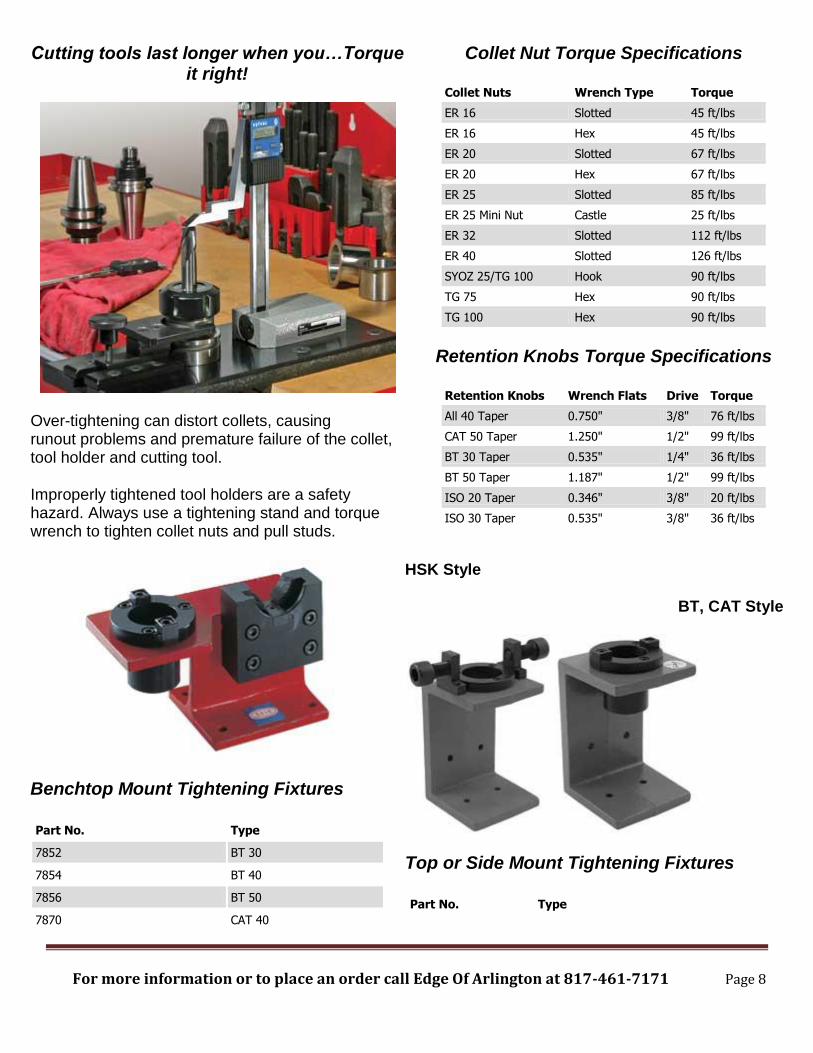
Cutting tools last longer when you…Torque it right!
Over-tightening can distort collets, causing runout problems and premature failure of the collet, tool holder and cutting tool.
Improperly tightened tool holders are a safety hazard. Always use a tightening stand and torque wrench to tighten collet nuts and pull studs.
Collet Nut Torque Specifications
Collet Nuts Wrench Type Torque
ER 16 Slotted 45 ft/lbs
ER 16 Hex 45 ft/lbs
ER 20 Slotted 67 ft/lbs
ER 20 Hex 67 ft/lbs
ER 25 Slotted 85 ft/lbs
ER 25 Mini Nut Castle 25 ft/lbs
ER 32 Slotted 112 ft/lbs
ER 40 Slotted 126 ft/lbs
SYOZ 25/TG 100 Hook 90 ft/lbs
TG 75 Hex 90 ft/lbs
TG 100 Hex 90 ft/lbs
Retention Knobs Torque Specifications
Retention Knobs Wrench Flats Drive Torque
All 40 Taper 0.750" 3/8" 76 ft/lbs
CAT 50 Taper 1.250" 1/2" 99 ft/lbs
BT 30 Taper 0.535" 1/4" 36 ft/lbs
BT 50 Taper 1.187" 1/2" 99 ft/lbs
ISO 20 Taper 0.346" 3/8" 20 ft/lbs
ISO 30 Taper 0.535" 3/8" 36 ft/lbs
For more information or to place an order call Edge Of Arlington at 817-461-7171 Page 9
7872 CAT 50
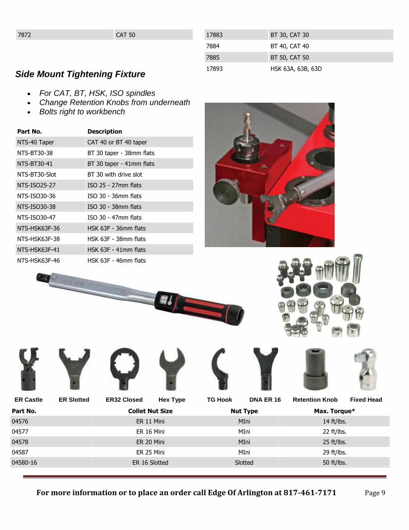
Side Mount Tightening Fixture
For CAT, BT, HSK, ISO spindles Change Retention Knobs from underneath Bolts right to workbench
Part No. Description
NTS-40 Taper CAT 40 or BT 40 taper
NTS-BT30-38 BT 30 taper - 38mm flats
NTS-BT30-41 BT 30 taper - 41mm flats
NTS-BT30-Slot BT 30 with drive slot
NTS-ISO25-27 ISO 25 - 27mm flats
NTS-ISO30-36 ISO 30 - 36mm flats
NTS-ISO30-38 ISO 30 - 38mm flats
NTS-ISO30-47 ISO 30 - 47mm flats
NTS-HSK63F-36 HSK 63F - 36mm flats
NTS-HSK63F-38 HSK 63F - 38mm flats
NTS-HSK63F-41 HSK 63F - 41mm flats
NTS-HSK63F-46 HSK 63F - 46mm flats
17883 BT 30, CAT 30
7884 BT 40, CAT 40
7885 BT 50, CAT 50
17893 HSK 63A, 63B, 63D
ER Castle ER Slotted ER32 Closed Hex Type TG Hook DNA ER 16 Retention Knob Fixed Head
Part No. Collet Nut Size Nut Type Max. Torque*
04576 ER 11 Mini MIni 14 ft/lbs.
04577 ER 16 Mini MIni 22 ft/lbs.
04578 ER 20 Mini MIni 25 ft/lbs.
04587 ER 25 Mini MIni 29 ft/lbs.
04580-16 ER 16 Slotted Slotted 50 ft/lbs.

For more information or to place an order call Edge Of Arlington at 817-461-7171 Page 10
04601-16 ER 16 Hex Hex 50 ft/lbs.
04580-20 ER 20 Slotted Slotted 75 ft/lbs.
04602-20 ER 20 Hex Hex 75 ft/lbs.
04603-25 ER 25 Slotted Slotted 95 ft/lbs.
04604-32 ER 32 Slotted Slotted 125 ft/lbs.
04605-40 ER 40 Slotted Slotted 140 ft/lbs.
03690-25 SYOZ 25/TG 100 Hook 100 ft/lbs.
04018-TWA TG 75 Slotted Hook 100 ft/lbs.
DNA16-TWA DNA 16 Slotted 50 ft/lbs.
04588-R ER 32 Slotted Slotted / Closed 125 ft/lbs.
SD-TWA SYOZ-20 Hook 45 ft/lbs.
Real lambskin provides the best cleaning. Use with any type of machine with a taper of 7/24 CAT, BT or DIN 69871.
Spindle Taper Wipers
For CAT, BT, HSK spindles Remove contaminants to improve T.I.R. Keeps spindles and tool holders clean
Spindle Taper Wipers
Part No. Taper Total Taper
17706 30 170mm 60mm
17707 40 188mm 78mm
17708 50 240mm 120mm
7710 HSK 63A 165mm 31mm
7711 HSK 63F 165mm 31mm
Available from Edge of Arlington Saw & Tool, Inc
Phone 817-461-7171 Tool Free (888) 461-7171
Fax 817-795-6651

For more information or to place an order call Edge Of Arlington at 817-461-7171 Page 11
Failure to properly maintain these parts can and will lead to expensive machinery and spindle
repairs; not to mention higher tool and machining costs.
Another critical area involves spoil boards, hold-downs and dust collection. Holding the part to be cut firmly and without movement or vibration is often the biggest challenge faced when cutting on a CNC. Chatter, movement, premature tool wear, tool breakage, poor edge finish and chipping are the result of inadequate hold-down. How well you can hold the part is perhaps the biggest factor in how fast you can cut. There is a lot of information on building dedicated spoil boards and jigs so we will only cover the basics. Some factors to consider include:
Some CNC operations are best suited to using flow through or suck through vacuum systems. Particularly well suited for cutting large parts and sheets of material; these types of router utilize replaceable spoil boards, so called because they are underneath the material being cut and are cut and “spoiled” during machining. The spoil board can then be re-surfaced and used again, sparing the router table underneath from damage. These types of systems are easy to use and require minimal maintenance. Using low (LDF) or medium density fiberboard (MDF); both sides are machined level using a large “fly” cutter to remove any imperfections or coatings. Vacuum is evenly distributed to the entire surface of the table. Air loss from the sides can be minimized by using rubberized or latex paint. Areas not being used should be sealed with sheets of laminate, plastic or other non-porous materials. Grooves resulting from the cutting process can cause vacuum leakage when cutting a variety of patterns; re-surfacing the spoil board should be done on a regular basis.
Smaller or more intricate parts are better suited to dedicated spoil boards due to vibrations and part movements. Cutting small parts can be challenging since a larger volume of air is lost due to the

For more information or to place an order call Edge Of Arlington at 817-461-7171 Page 12
number of channels cut between parts. As more parts are cut – more air pressure is lost, resulting in vibration and part movement.
Leaving a thin skin (onion skin) or programming tabs at certain points can help to hold small parts together but require a secondary routing or sanding operation.
Use dedicated spoil boards for recurring part runs. Taking the time to make a proper spoil board will pay for itself by allowing faster feed rates, giving you a better finish and prolonging tool life.
Weather stripping is not gasket tape! The repeated compression and stress the tape is subjected to, requires a more flexible, crush resistant material. A quick search on Yahoo will provide you with numerous sources.
Gasket tape should be applied in a channel to establish the outside perimeter of the part being cut. The channel should be roughly half the thickness of the tape with a 1/16” side clearance to allow for compression. Without a channel, the tape will simply compress and lose its memory, allowing the part to vibrate – resulting in wear and finish degradation.
Drilling a few holes in a piece of MDF or particle board is not a proper spoil board. This technique may suffice in some instances; particularly large, thick pieces but is not satisfactory in most situations and will contribute to tool wear and finish degradation. Simple holes create pressure points and allow parts to move, vibrate and flex.
Grooving the interior area of a dedicated spoil board will allow the vacuum to flow evenly to all areas of the part to be cut; holes should be drilled inside the channels of the vacuum grid allowing for a more even vacuum.
When designing a dedicated spoil board, don’t be afraid of being creative. If the material is thin and wants to flex, a combination of grooves and “supporting walls” can work very well.
Deeper grooves along the router path can be used to give chips a place to go when using a down shear geometry.
Plateaus for the part to rest upon (sealed along the edges) can allow small scrap parts to fall safely to the spoil board instead of becoming projectiles. There are as many variations as there are part configurations; the main goal is to allow vacuum to flow to all corners of the part and at the same time giving support where needed to minimize part movement and vibration.
Pods are great for large pieces and when you need access to the underside of a piece - such as putting a bull-nose on the edge or doing horizontal drilling on a point to point. Pods are not as well suited to manufacturing small parts and “cookie” cutting; in these instances you may be able to adapt your pod system to use a spoil board – see your machinery dealer.

For more information or to place an order call Edge Of Arlington at 817-461-7171 Page 13
Most spoil boards are ¾” thick. If you prefer a thicker spoil board, use a product such as Sierra Pine’s 2” thick LDF.
Most manufacturers recommend 38-45 lb MDF.
The higher the CFM the better for holding small parts. When working with a pump with low CFM’s a thicker spoil board (1-1/4” to 2” thick) may work better on small parts because although it allows less air to flow; it also lets less air to escape. A high CFM pump would be one that ran 450 CFM and above.
Consult your machinery dealer regarding other hold down options and for technical assistance.
Some machinery dealers offer roller-hold-downs. These are particularly useful when you are dealing with materials that are subject to warping. Warped material can be difficult to cut and may cause damage to tooling as material stress is released during cutting. A roller-hold-down by itself is not usually sufficient to give you a quality finish; they should be used in conjunction with a good vacuum and spoil board system.
A properly maintained dust collector is important to remove the dust (and with it heat). Much of the dust generated can be a health hazard and should not be breathed in. Consult the manufacturers MDS sheets for chemical contents.
Overly long bristles can cause small parts to move and should be trimmed with a pair of scissors.
Filters should be inspected and/or cleaned daily.
Check pressure gauges and make a note of what they should read. If you are not sure, consult your machinery dealer or manual.
Today’s CNC can do just about anything. Techniks has a line of Aggregate heads that will enable you to chuck up just about any tool.
Quattro: 4-drive output head Duo: 2-drive output head Add sawing capability to your CNC

For more information or to place an order call Edge Of Arlington at 817-461-7171 Page 14
Our aggregate heads outperform the competition. We guarantee it.
We can say this because our aggregate heads are designed by ex-Benz engineers, who knew the weak points of the Benz design and corrected them. Only the best components, manufactured to the highest quality, make it into our aggregate heads. All our parts are painstakingly checked for quality.
For example, our bevel gears are subject to a 90 point inspection that measures the gear's overall 3D shape, the taper of the teeth, and the consistency of the tooth spacing and angle. Our standard for gear tolerance is 1/200th of a millimeter. Our competitor's is .5mm.
Our manufacturing process makes the difference.
Each of our aggregate heads is individually hand-assembled by a highly skilled technician, who is personally responsible for build quality. That's right; one craftsman does the whole job from start to finish.
Once the assembly is complete, the technician performs a test run of the aggregate for 30 minutes. After the post-run inspection and measurement, the technician finishes sealing the aggregate and signs his name to the inspection report verifying that it has passed his personal inspection.
‘

For more information or to place an order call Edge Of Arlington at 817-461-7171 Page 15
Climb cut vs. conventional cut: Climb and conventional cutting refer to the direction of travel in
relation to spindle rotation. In the case of a right-hand rotation spindle - climb cutting (clockwise direction)
can produce a different result than conventional cutting (counter-clockwise direction).
In many circumstances conventional (CCW) cutting will provide the best finish; especially in plastics and with larger diameter tools.
If the scrap piece has a better finish than the finished part; a change in cutting direction will provide you with the opposite results. Don’t be afraid to experiment with cutting directions or have different cutting directions on the same work-piece.
There are also left-handed tools and holders available for left-hand rotation – climb cutting would then become counter-clockwise and conventional cutting would become clockwise.
When cutting the interior of a part as opposed to the outside perimeter, conventional cut becomes climb cut and vice versa.
When cutting two parts with one pass such as when cutting parts that are nested or mirrored, keep in mind that one side of the cut will be conventional cut and the other will be climb cut.
Climb cutting is more aggressive and can move small parts.
When cutting hard materials and metals such as aluminum, climb cutting is preferred.
Tool Materials:
High speed steel (HSS). Used primarily on soft woods such as pine, aluminum, and soft plastics. HSS can be sharpened to a very sharp edge and at the appropriate hook and clearance angles “slices” through soft material reducing pre-splitting. HSS is more impact resistant than carbide but is not wear resistant enough to hold up to many of today’s man-made materials.
Tangtung (TG) A cast alloy material with a high tungsten content. Tangtung retains its hardness at very high temperatures, is more shock resistant than carbide and resists corrosion from wood acids. Tangtung, like HSS can be sharpened to a fine edge and is primarily used in hardwoods for a superior cross-grain cut. TG can and has been used in insert tooling for CNC applications; Freeborn Tool has a line of insert shaper cutter available in Tangtung. Tangtung is never recommended for manmade fiber boards or plywood.
Carbide tipped (CT). Used primarily on hard woods, laminates, composite materials and for abrasive or resin based products. Carbide is welded or brazed onto a steel body and profiled to the desired pattern; therefore it is the most common type of material used for profile and custom tooling. There are many different grades of carbide; the harder the grade of carbide, the more likely it is to break during the heating and cooling process in manufacturing – problems overcome with insert tooling.
Solid carbide (SC). Used primarily on hard woods, wood composites, laminates, plastics, aluminum, and other composite materials for longer life and faster feed rates. Solid carbide can be cast into just about any shape. Solid Carbide rods are well suited for making router bits with spiral geometries and small form or profile tools. Solid carbide blanks are also well suited for insert tooling and are available in many standard sizes and configurations. Solid carbide is very wear resistant but not impact resistant, strain and deflection often lead to tool breakage.
Diamond (PCD). Polycrystalline diamond is used primarily on composite materials such as melamine. PCD diamond is extremely heat and wear resistant (100+ times carbide) but is not impact resistant; in fact it chips fairly easily. Materials must be free of all foreign matter and be homogenous in nature or

For more information or to place an order call Edge Of Arlington at 817-461-7171 Page 16
tool damage may result. Machine condition and maintenance are vital to cost effectiveness. High initial cost but very low operating cost can make diamond tooling a very economical alternative. Diamond wafers are brazed on to a steel body and are not suited to small sizes.
Insert tooling. Insert tooling can provide consistency in production. Using replaceable inserts instead of brazed-on-carbide allows you to maintain a constant diameter. Insert tooling is also able to utilize harder, more wear resistant carbide than traditional CT tooling. While very versatile in nature; the design does not lend itself well to small diameters due to the need to affix the insert with Gibbs and/or screws.
Tool geometry: There are a lot of different geometries involved in making a router bit - clearance angles,
grinding angles, hook angles, axle angles, side clearance angles, radial clearance angles and side rake. For the purposes of our discussion we will only talk about the basics.
Tool size is a determining factor in how fast you can cut and what types of geometries and clearance angles are possible; all major factors in productivity, finish and consistency of parts.
Choose the shortest cutting length possible for stability. You should have sufficient shank to fill 80% of the collet. Longer router bits will deflect more, also run-out is more exaggerated the longer the tool.
The larger the diameter of the tool the faster you can go – up to a point. While a ¾” diameter bit will be able to handle a much larger chipload than a 1/8” diameter bit; larger bits require slower speeds for safety reasons. The following are general safety guidelines:
Up to 1” Diameter – Maximum of 24,000 RPM 1” to 1-1/2” Diameter – Maximum of 18,000 RPM 1-1/2” to 2-1/4” Diameter – Maximum of 16,000 RPM 2-1/4” to 3” – Maximum of 14,000 RPM 3” to 3-1/2” Diameter – Maximum of 12,000 RPM
Use the largest shank possible; however, cutting diameters smaller than the shank diameter cause stress points at the transition and can contribute to breakage. Solid carbide tools larger than ½” in diameter can be expensive and are designed when extra long lengths are needed. The following are safety guidelines with relation to shank size and head diameter:
1/2” diameter shank: Maximum large diameter is 2” 1/2” diameter shank: Minimum small diameter is 1/2” 1/2” diameter shank: Maximum overall length is 4”
5/8” diameter shank: Maximum large diameter is 3” 5/8” diameter shank: Minimum small diameter is 5/8” 5/8” diameter shank: Maximum overall length is 4-1/2”
3/4” diameter shank: Maximum large diameter is 3-1/4” 3/4” diameter shank: Minimum small diameter is 5/8” 3/4” diameter shank: Maximum overall length is 5”
Straight flute tools are most often found in hand routing operations. They can also be very useful in CNC applications; especially when you are not using laminates and you cannot take advantage of the

For more information or to place an order call Edge Of Arlington at 817-461-7171 Page 17
fast speeds possible with spiral tooling. Straight flute tools have a neutral effect on cutting pressure (neither up nor down) and they may chip laminates. Straight flute tools can be useful when cutting thin materials and plastics where lifting of the part is a problem. Straight flute tools can be “V” or “O” flute design (look down the face of the tool; an O-flute has a half moon appearance a V-flute looks like a
“V”). Hard, rigid plastics cut well with straight V-flute tools, soft plastics with O-flute tools. Brazed tools can also be supplied with a carbide boring point for use when plunging.
Shear / helix CT router bits can be down-shear or up-shear or both. These are not spiral bits; but modified straight bits. Down-shear bits are the most common and usually have only a slight angle, 3 degree or so. This design allows for a chip free cut on the top of the material (bottom if up-shear) and is frequently found in the manufacture of shelving using hand routers and the routing of dadoes and other grooving applications. Edge of Arlington is a distributor of “Her-Saf” cutters which are probably the best known example of this type bit, they have developed a complete line of reverse helix, screw-
on cutters in both CT and insert designs that provide an exceptional finish when cutting dadoes.
Up-cut spirals will aid in fast chip removal. When cutting all the way through the material, the up-cut will produce a smooth finish on the bottom but may fray or chip on the top, especially on entry into the material. Up-cut spirals are preferable when grooving, slotting or when fast chip removal is required, such as cutting soft plastics. Up-cut spirals will try to pull the material from the table so a good hold
For more information or to place an order call Edge Of Arlington at 817-461-7171 Page 18
down system is very important. Up-cut spirals are not recommended when stacking material due to the tendency of the material to move.
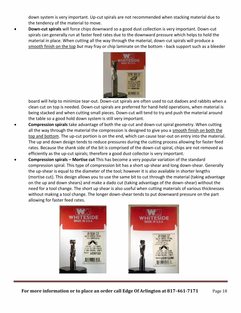
Down-cut spirals will force chips downward so a good dust collection is very important. Down-cut spirals can generally run at faster feed rates due to the downward pressure which helps to hold the material in place. When cutting all the way through the material, down-cut spirals will produce a smooth finish on the top but may fray or chip laminate on the bottom - back support such as a bleeder
board will help to minimize tear-out. Down-cut spirals are often used to cut dadoes and rabbits when a clean cut on top is needed. Down-cut spirals are preferred for hand-held operations, when material is being stacked and when cutting small pieces. Down-cut will tend to try and push the material around the table so a good hold down system is still very important.
Compression spirals take advantage of both the up-cut and down-cut spiral geometry. When cutting all the way through the material the compression is designed to give you a smooth finish on both the top and bottom. The up-cut portion is on the end, which can cause tear-out on entry into the material. The up and down design tends to reduce pressures during the cutting process allowing for faster feed rates. Because the shank side of the bit is comprised of the down-cut spiral, chips are not removed as efficiently as the up-cut spirals; therefore a good dust collector is very important.
Compression spirals – Mortise cut This has become a very popular variation of the standard compression spiral. This type of compression bit has a short up-shear and long down-shear. Generally the up-shear is equal to the diameter of the tool; however it is also available in shorter lengths (mortise cut). This design allows you to use the same bit to cut through the material (taking advantage on the up and down shears) and make a dado cut (taking advantage of the down-shear) without the need for a tool change. The short up shear is also useful when cutting materials of various thicknesses without making a tool change. The longer down-shear tends to put downward pressure on the part allowing for faster feed rates.

For more information or to place an order call Edge Of Arlington at 817-461-7171 Page 19
Single flute router bits are often used when heat is a problem due to the inability to run fast – such as routing holes. The single flute takes a larger “bite” than a multiple flute router bit at the same feed and speed; giving you a larger chipload – therefore removing more heat. They are also appropriate on small diameters where breakage may be a problem.
Double flute router bits are the most common. They may give you a better finish than a single flute router bit at similar feeds and speeds and will give you a satisfactory finish in most cutting situations.
Three and four flute router bits are used for very fast speeds and some finishing operations. Older model machines and intricate parts may make it impossible to fully utilize this type of bit. The multiple flutes require fast speeds in order to produce a chip large enough to remove the heat from the material being cut. The three flute geometry is found in many finishing tools – designed to remove a small amount of material (.015 to .080) after a rough cut or hogging operation. Taking too small of a finish cut can cause finish degradation as the bit skips across the surface because it doesn’t have enough material to bite in to.
Chip-breaker spirals and rougher/hoggers are regular spiral bits that have “grooves” or “slots” cut into the flutes at staggered positions. These “grooves” act as chip-breakers that allow you to run at higher feed speeds and are primarily used in roughing or hogging operations. Chip-breakers can also help to reduce pre-splitting when cutting across the grain.
O-flute “O” flute tools have a rounded, half moon appearance as you look down the face of the flute. This geometry is most often used in machining aluminum and plastics and can be made of HSS or SC. The rounded flute allows for better chip removal; especially important in preventing “chip-welding” when machining soft plastics such as ABS. O-flute tools can have spiral or straight geometries, straight O-flute geometries are commonly used in air routers on most types of plastics.

For more information or to place an order call Edge Of Arlington at 817-461-7171 Page 20
Chipload: In order to get the most out of your CNC you must have a firm understanding of chipload. It is
the main factor that you have direct control over.
In the simplest terms chipload refers to the size of the chip produced during machining. The chip size is controlled by the how fast the spindle is turning (RPM) and how fast the router is moving (Feed Rate). Assuming a 1 flute tool, the chipload would be equal to the distance of travel during 1 revolution of the spindle. For a 2 flute too; the chipload would be equal to ½ the distance traveled in 1 revolution.
A tool will only make so many cuts; make the most out of them. If the dust collection is not functioning properly and the waste material is not removed from the cut, the chips may be repeatedly pulled into the cutting circle. This can cause the cutting life of the tool to be reduced by as much as 5o%.
You can use the following formula to determine what your chipload is; or if you know what chipload is desired you can work backwards to figure feed and speeds required to reach your target. A difference of as little as .001” in chipload can mean a dramatic difference to the bottom line.
Chipload = Feed rate in IPM / (RPM x #Flutes)
Feed Rate in IPM = RPM x #Flutes x Chip Load
Speed (RPM) = Feed Rate in IPM / (#Flutes x Chip Load)
Recommended chipload varies from material to material. A general rule of thumb is that the harder, more dense the material, the smaller the chipload. On the other hand, heat is a function of surface footage per unit of time, the denser the material, the faster the feed rate needed to minimize heat build-up. A delicate balancing act to be sure. Variations in RPM and feed rate can produce dramatically different results.
o Natural Woods - .012” to .025” o Plywood with Veneers - .003” to .015” o Masonite - .003” to .015” o Laminated Plastics - .003” to .008” o Acrylics - .001 to .005” o Particle Board - .010” to .025”
You may have noticed that the above ranges are pretty large. You can cut at a higher feed rate (chipload) when using a spiral router bit than a straight flute bit and higher still with a compression bit. Also, the better you holding ability the larger the chipload possible.
Don’t be afraid to push it a little. Pick at starting point, and adjust feed rate up from there. At some point the chipload will become too great and the part will begin to move or the finish to degrade as the bit begins to deflect.
Sometimes it is easiest to change the RPM; make adjustments at 10% increments until you minimize the heat; then use the above formulas to recalculate feed and speed to maximize machine time. Change only one variable at a time and observe the results.
Chipload is important because the chip takes the heat way from the tool and heat is the biggest cause of tool wear and failure.
Keep in mind that other factors are working against you as you try to determine the proper chipload. Plunging, deceleration at corners, small parts, holes & cut-outs and other such factors will contribute to heat buildup.

For more information or to place an order call Edge Of Arlington at 817-461-7171 Page 21
Some fibrous materials simply will not produce a chip, only fine dust. In such instances go as fast as you can. Good dust collection will help and sometimes air cooling can be utilized to improve efficiency.
When determining the proper feed and speed it is important to ascertain if the machine is actually achieving the programmed speeds. You may program at 900 IPM but if you are cutting small or intricate parts it is doubtful that you will ever achieve your programmed speed – in this circumstance you can control heat by decreasing RPM or changing the type/geometry of the tool.
Sometimes it is necessary to make compromises, find the weakest link and work from there.
Feeds & Speeds:
You should keep in mind the other factors we discussed as we talk about feeds and speeds, in particular
your hold down ability.
At the proper feed and speed, the chipload should be sufficient to remove the heat; in most circumstances, the tool will be at or near room temperature immediately after cutting. Burning or heat marks on the tool or the part are indications that you are running at too high of a RPM for the programmed feed rate.
The following is a starting point only- adjust feed and/or speed in 5% to 10% increments and observe the results, then fine tune in smaller increments until you find “the sweet spot”. The general rule is that the faster a bit is fed, the longer the life of the tool.
Feed rate is the controlling factor in productivity so the ultimate goal is to maximize feed rate. Push the feed rates to the limits of finish and tool integrity for optimum profits.
The following calculations are based on 18,000 RPM using a 1/2" diameter router bit on 3/4" material. The feed rate is expressed in inches per minute. For other diameters and thicker materials use the following multipliers:
1/4" diameter tools - reduce feed by 40%. 3/8" diameter tools - reduce feed by 20%. 5/8" diameter tools - increase feed by 20%. 3/4" diameter tools - increase feed by 40%.
When cutting thicker material decrease feed rate by 25% for each multiple of 3/4" (1-1/2" reduce 25%, 2-1/4" reduce 50%).
Multiple passes may also be necessary on thicker materials – the general rule of thumb is to make multiple passes when the depth of cut is more than 3 times the cutting diameter for larger tools and 2 times the diameter for smaller tools.
Feed rate has a linear relation to spindle speed (RPM). Assuming you are running at optimal speed; the higher the RPM the faster the feed rate possible (10% RPM increase = increase feed by 10%, 20% RPM reduction = reduce feed by 20%). This means that if you have an appropriate chipload and the tool is running cool and you increase the RPM by 10%, you can increase the feed rate by 10% while maintaining the same chipload.
If you know the feed rate you would like to run at, use the chipload formula to determine what your RPM and chipload would have to be in order to achieve your goal. There are 4 variables involved in the calculation – feed rate in IPM, spindle speed in RPM, the number of flutes in the tool and the chipload. If you can assign numbers for 3 of the 4 variables, you can solve the equation to find the other.

For more information or to place an order call Edge Of Arlington at 817-461-7171 Page 22
Tool type Soft Wood Hardwood PB & Plywood MDF
Carbide tipped Straight 250 IPM 300 IPM 350 IPM 400 IPM
1F Up-cut Or Down-cut 200 IPM 300 IPM 350 IPM 400 IPM
2F Up-cut Or Down-cut 250 IPM 350 IPM 400 IPM 500 IPM
2F Up-Down Compression 350 IPM 400 IPM 500 IPM 600 IPM
3F Up-Down Compression 450 IPM 750 IPM 800 IPM 800 IPM
While the above feed rates are a safe starting point, much higher feed rates can and have been achieved.
More detailed charts are available over the internet from tooling manufacturers. While charts are useful to an extent – they give you a starting reference, there is no substitution for trial, error and experience.
Things to Avoid:
Dead stops; also known as “dwelling in the cut,” can lead to premature tool wear and failure. When changing directions of travel or when cutting small pieces a 1 second stop at 18,000 RPM generates enormous heat and no means of extraction. Imagine rubbing your hands together 300 times per second – a sure way to get a blister. This is more of a machinery and software issue. Certain programming techniques can help to compensate, such as ramping, use of loops at sharp outside corners and the use of exit ramps.
Plunge cutting, while this is the oldest and most widely used method of entering the material, it is not always the most efficient. Plunge cutting can lead to chips wrapping around the router bit after repeated plunges. Whenever possible you should Ramp into the cut. This eliminates the heat generated during the plunging process and can eliminate burn marks at the plunge point. Plunging can also cause the bit to “walk” because there is no centering point; this will be evident as ovals holes and entry points larger than the diameter of the tool. If you cannot ramp in; a good alternative is to plunge down outside of the work-piece and enter from the side. Spiraling in can also help, whatever it takes to keep the router bit moving.
Routing holes is never the optimum choice. Use drills for drilling – routers for routing. Drills turn at much lower RPM than routers do; router bits generate too much heat when drilling. Drilling just a couple of holes per sheet will significantly reduce the life of your tooling; in fact, you will probably dull more drilling the 2 holes than cutting the entire piece. If you do not have drill heads to take advantage of European type boring bits, turn the RPM down as low as possible; 4-5000 RPM at most, and plunge as fast as possible, an upshear will help to remove the chips if hold down is not a problem. On deep holes “pecking” can sometimes help.
Small parts and scrap pieces can become projectiles if left after the cutting process without sufficient hold down. They can also be sucked into the dust collector and cause a blockage. Skin cutting and the use of tabs can help to hold small parts.

For more information or to place an order call Edge Of Arlington at 817-461-7171 Page 23
Over-tightening of the collet and collet nut is a common mistake. Most operators assume that the tighter the better – this is not true and can lead to premature tool and collet wear and tool breakage. Collets are the most misunderstood and overlooked part of the CNC, often times the cause of poor finish, short tool life, and unnecessary machine wear. Collets are made of spring steel and are subject to distortion when put under undue pressure. It is highly recommended that collets be tightened to manufacturers’ specifications with the use of a torque wrench
Fires, yes it happens. A tool left in the same place for a sufficient amount of time can and will start a fire. It is important to never leave a CNC running without an operator; you wouldn’t believe how fast things can go wrong. The dust collection system and the vacuum system will aid in the fires speedy travel. If this ever happens to you, beware of flash-back when the vacuum is turned off. When it is safe to do so, it is important to remove and examine the bleeder board and table underneath, embers can remain and once again flair up.
Understanding the different variables involved in CNC routing can be overwhelming, especially
to anyone new to CNC’s. That is why Edge of Arlington Saw & Tool is here; to help you in selecting the
proper tool for the job. Don’t let the complexities involved keep you from maximizing tool life, machine
time and profits – help is only a phone call way.
Please let me know if you have any additions, corrections or contributions to the above
material that you would like to share with others. Information presented here has been gathered over
many years from various sources.
The preceding is based on 20+ years of experience helping customers to achieve their goals. It is
intended as a guide only. Thanks to the many mentors that I have had over the years, from customer to
vendors. There are helpful articles and lots of useful information available online. From trade
magazines to tooling manufacturers, I encourage you to seek out more information. Don’t’ settle for
broken and burned tooling, take the time to do it right – even after 20 years I am still learning.
Thom Snellings
President
Edge Of Arlington Saw & Tool, Inc.
Office (817) 461-7171 Cell (817) 919-7914 Fax (817) 795-6651 Email [email protected]

For more information or to place an order call Edge Of Arlington at 817-461-7171 Page 24
INDEX
Pages
Aggregate Heads 13-14
Bit Speed Guidelines 16
Bit Shank Diameter Guidelines 16
Chip-Breaker Spirals and Rougher/Hoggers 19
Chipload 3, 20-21
Climb Cut vs. Conventional Cut 15
Collets 2, 5, 6, 7
Collet Nut Torque Specifications 8
Compression Spirals 18
Compression Spirals-Mortise Cut 18
Double Flute Router Bits 19
Down-Cut Spirals 18
Drilling 6
Dust Collection 5, 11, 13
Feed and Speed 6, 21-22
Heat 3, 5
Hold-Down for Materials 4, 11, 13
Machinery 5
Materials Being Cut 6
Man-made 6
Laminates 6
O Flute Tools 19
Operator Responsibilities 4
Programming Necessities 4

For more information or to place an order call Edge Of Arlington at 817-461-7171 Page 25
Safety
Dust 5, 13
Set-up Fixture 7, 8
Bit Speed 16
Bit Diameter 16
Things to Avoid 22-23
Retention Knobs Torque Specifications 8
Shear/Helix CT Router Bits 17
Single Flute Router Bits 19
Spindle Taper Wipers 7, 10
Spoil boards 11-13
Straight Flute tools 16, 17
Things to Avoid 22-23
Three and Four Flute Router Bits 19
Tightening Fixtures 8, 9, 10
Tool Holder 6, 7
Tool Selection 3
Sharpness 5
Type 5
Geometry 6, 16
Tool Materials 15, 16
Torque wrench 2, 5, 7, 8
Up-Cut Spirals 17, 18
Vibration 5