co-1 cooling system - sugarlump kennel cooling system description co-2 troubleshooting co-4 check...
TRANSCRIPT
CO-1
COOLING SYSTEM
DESCRIPTION CO-2TROUBLESHOOTING CO-4CHECK AND REPLACEMENT OF
ENGINE COOLANT CO-4WATER PUMP CO-6THERMOSTAT CO-10RADIATOR CO-12
Page

CO-2 COOLING SYSTEM - Description
DESCRIPTIONThis engine utilizes a pressurized water forced circulation cooling system which includes a thermostat equippedwith a by-pass valve mounted on the inlet side.
IPZ and 1HZ
From Heater
To Heater
ThermostatRadiator
1HD-T
From Heater
To Heater
ThermostatRadiator
C01049C01050

CO-3COOLING SYSTEM - Description
The cooling system is composed of the waterjacket (inside the cylinder block and cylinder head),radiator, water pump, thermostat, cooling fan,hoses and other components. Coolant which isheated in the water jacket is pumped to the radiator,where it is cooled by the cooling fan and the vehiclewindstream. Coolant which has been cooled is thensent back to the engine by the water pump, whereit cools the engine. The water jacket is a network ofchannels in the shell of the cylinder block andcylinder head through which coolant passes. It isdesigned to provide adequate cooling of the cylin-ders and combustion chambers which become thehottest during engine operation.
RADIATORThe radiator performs the function of cooling the
coolant which has passed through the water jacketand become hot, and it is mounted in the front ofthe vehicle. The radiator consists of an upper tankand lower tank, and a core which connects the twotanks. The upper tank contains an inlet for coolantfrom the water jacket and a filler inlet. It also has ahose through which excess coolant or steam canflow. The lower tank has an outlet and drain cockfor the coolant. The core contains many tubes andcooling fins through which coolant flows from theupper tank to the lower tank so that coolant hasbeen heated up as it passes through the waterjacket is cooled heae by the air sucked through theradiator by the cooling fan, as well as by the windgenerated by the vehicle's travel. Models with anautomatic transmission include an automatic trans-missions fluid cooler built into the lower tank of theradiator.
RADIATOR CAPThe radiator cap is a pressure type cap which
seals the radiator, resulting in pressurization of theradiator as the coolant expands. The pressurizationprevents the coolant from boiling even when thecoolant temperature exceeds 100°C (212°F). Arelief valve (pressurization valve) and a vacuumvalve (negative pressure valve) are built into theradiator cap. When the pressure generated insidethe cooling system exceeds the limit (coolanttemperature: 110-120°C, 230 - 248°F, pressure;0.3-1.0 kg/cm2, 4.3-14.2 psi, 29.4-98.1 kPa)the relief valve is opened by the pressure and letssteam escape through the overflow pipe. The vac-uum valve opens to allow atmospheric air to enterto alleviated the vacumm which develops in thecooling system after the engine is stopped and thecoolant temperature drops. The valve's openingallows the pressure in the cooling system to returnto the reservoir tank.
RESERVOIR TANKThe reservoir tank is used to catch coolant which
overflows the cooling system as a result of volu-metric expansion when the coolant is heated. Whenthe coolant temperature drops the coolant in thereservoir tank returns to the radiator, thus keepingthe radiator full at all times and avoiding needlesscoolant loss. To find out if the coolant needs to bereplenished, check the reservoir tank level.
WATER PUMPThe water pump is used for forced circulation of
coolant through the cooling system. It is mountedon the front of the cylinder block and driven by adrive belt.
THERMOSTATThe thermostat has a wax type by-pass valve and
is mounted in the cylinder block. The thermostatincludes a type of automatic valve operated byfluctuations in the coolant temperature. This valvecloses when the coolant temperature drops, pre-venting the circulation of coolant through the radi-ator and thus permitting the engine to warm uprapidly. The valve opens when the coolant temper-ature has risen, allowing the circulation of coolant.Wax inside the thermostat expands when heatedand contracts when cooled. Heating the wax thusgenerates pressure which overpowers the force ofthe spring which keeps the valve closed, thusopening the valve. When the wax cools, its con-traction causes the force of the spring to take effectonce more, closing the valve. The thermostat in thisengine operates at a temperature of 76°C (169°F).

CO-4 COOLING SYSTEM Troubleshooting, Check and Replacement of Engine Coolant
HINT: Removal of the thermostat would have an adverse effect, causing a lowering of cooling efficiency. Do not re-move the thermostat, even if the engine tends to overheat.
TROUBLESHOOTING
Engine overheats Fan belt loose or missingDirt, leaves or insects on radiator orcondenserHoses, water pump, thermostat housing,radiator, heater, core plugs or head gasketleakageThermostat faultyInjection timing retardedFluid coupling faultyRadiator hose plugged or rottedWater pump faultyRadiator plugged or cap faultyCylinder head or block cracked orplugged
Adjust or replace beltsClean radiator or condenser
Repair as necessary
Check thermostatAdjust timingReplace fluid couplingReplace hoseReplace water pumpCheck radiatorRepair as necessary
CH-5CO-12
CO-10EM-24CO-7
CO-7CO-12
CHECK AND REPLACEMENT OFENGINE COOLANT1. CHECK ENGINE COOLANT LEVEL AT RESERVOIR TANK
The coolant level should be between the "LOW" and"FULL" lines.If low, check for leaks and add coolant up to the "FULL"line.
2. CHECK ENGINE COOLANT QUALITYThere should not be any excessive deposits of rust or scalesaround the radiator cap or radiator filler hole, and thecoolant should be free from oil.If excessively dirty, replace the coolant.
3. REPLACE ENGINE COOLANT(a) Remove the radiator cap.CAUTION: To avoid the danger of being burned, donot remove it while the engine and radiator are stillhot, as fluid and steam can be blown out under pres-sure.(b) Drain the coolant from the radiator and engine drain
cocks.(c) Close the drain cocks.Torque (Engine drain cock):
250 kg-cm (18 ft-lb, 25 N-m)
CO0928
C00940
CO0942
DrainCock

CO-5COOLING SYSTEM - Check and Replacement of Engine Coolant
(d) Fill the system with coolant.Use a good brand of ethylene-glycol or TOYOTAradiator conditioner or equivalent anticorrosive, mixedaccording to the manufacturer's directions.
Ethylene-glycol type: This type has an antifreeze andanticorrosive effect.TOYOTA radiator conditioner: This has only an anticorro-sive effect.NOTICE:• Do not use alcohol type coolant.• The coolant should be mixed with demineralized
water or distilled water.Capacity (w/o Heater):
PZJ70, 73, 759.6 liters (10.1 US qts, 8.4 Imp. qts)
HZJ70, 73, 75M/T 9.9 liters (10.5 US qts, 8.7 Imp. qts)A/T 9.7 liters (10.3 US qts, 8.5 Imp. qts)
HZJ80 and HDJ80M/T 10.4 liters (11.0 US qts, 9.2 Imp. qts)A/T 10.2 liters (10.8 US qts, 9.0 Imp. qts)
HZB30 and HDB3010.2 liters (10.8 US qts, 9.0 Imp. qts)
Capacity (w/ Heater):PZJ70, 73, 75
10.3 liters (10.9 US qts, 9.1 Imp. qts)HZJ70, 73, 75
M/T 10.6 liters (11.2 US qts, 9.3 Imp. qts)A/T 10.4 liters (11.0 US qts, 9.2 Imp. qts)
HZJ80and HDJ80M/T 11.1 liters (11.6 US qts, 9.8 Imp. qts)A/T 10.9 liters (11.5 US qts, 9.6 Imp. qts)
HZB30 and HDB3014.6 liters (15.4 US qts, 12.8 Imp. qts)
Capacity (w/ Front and rear heaters):PZJ70, 73 75
11.3 liters (11.9 US qts, 9.9 Imp. qts)HZJ70, 73, 75
11.6 liters (12.2 US qts, 10.2 Imp. qts)HZJ80 and HDJ80
M/T (Europe)12.0 liters (12.7 US qts, 10.6 Imp. qts)
A/T (Europe)11.8 liters (12.5 US qts, 10.4 Imp. qts)
M/T (Others)11.9 liters (12.6 US qts, 10.5 Imp. qts)
A/T (Others)11.7 liters (12.4 US qts, 10.3 Imp. qts)
(e) Reinstall the radiator cap.(f) Warm up the engine and check for leaks.(g) Recheck the coolant level and refill as necessary.

CO-6 COOLING SYSTEM Water Pump
WATER PUMPCOMPONENTS
Camshaft Oil Seal Retainer
No.2 TurboWater PipeAlternator Adjusing Bar
200(14,20)200(14,20)
400 (29, 39)
Drive Belt
GasketWater Pump
200(14,20)
Water Pump Pulleyw/o Fluid Coupling
Fan Spacer
w/ Fluid Coupling
200 (14,20)
Fluid Coupling
Fan200(14,20)
200(14,20)
Fan200(14,20)
Specified torqueNon-reusable part CO0956
kg-cm (ft-lb, N-m)

CO-7COOLING SYSTEM - Water Pump
REMOVAL OF WATER PUMP(See page CO-6)
1. DRAIN ENGINE COOLANT (See page CO-5)
2. REMOVE DRIVE BELT, FAN AND WATER PUMPPULLEY(a) Stretch the belt tight and loosen the four pump pulley
set nuts.(b) Loosen the pivot bolt, lock bolt and adjusting bolt,
and remove the drive belt.(c) Remove the four nuts, fan and fluid coupling (fan
spacer) assembly and pulley.
3. REMOVE TIMING BELT AND IDLER PULLEY(See steps 1 to 4 on pages EM-33 to 34)
4. REMOVE NO.1 CAMSHAFT TIMING PULLEY(See steps 6 to 8 on pages EM-34 to 35)
5. REMOVE CAMSHAFT OIL SEAL RETAINER(See step 14 on page EM-55)
6. REMOVE WATER PUMP(a) (1HD-T)
Disconnect the turbo water by-pass hoses.(b) Remove the three bolts and alternator adjusting bar.
(c) Remove the five bolts, two nuts, No.2 turbo waterpipe (1 HD-T), water pump and gasket.
CO0957
EM8284
CO0955

CO-8 COOLING SYSTEM - Water Pump
INSPECTION OF WATER PUMP1. INSPECT WATER PUMP
Turn the pulley and check that the water pump bearingmoves smoothly and quietly.If necessary, replace the water pump.
2. INSPECT FLUID COUPLINGCheck the fluid coupling for damage and silicon oil leakage.If necessary, replace the fluid coupling.
INSTALLATION OF WATER PUMP(See page CO-6)
1. INSTALL WATER PUMP(a) Install a new gasket, the water pump and No.2 turbo
water pipe (1 HD-T) with the five bolts and two nuts.Torque: 200 kg-cm (14 ft-lb, 20 N-m)
(b) Install the alternator adjusting bar with the two bolts(A).
Torque: 400 kg-cm (29 ft-lb, 39 N-m)(c) Temporarily install the lock bolt (B).(d) (1HD-T)
Connect the water by-pass hoses.
2. INSTALL CAMSHAFT OIL SEAL RETAINER(See step 6 on page EM-79)
3. INSTALL NO.1 CAMSHAFT TIMING PULLEY(See steps 1 to 3 on page EM-38)
4. INSTALL IDLER PULLEY TIMING BELT(See steps 5 to 11 on pages EM-39 to 41)
CO0927
CO0926
CO0954
EM8285
CO-9COOLING SYSTEM - Water Pump
CO0957
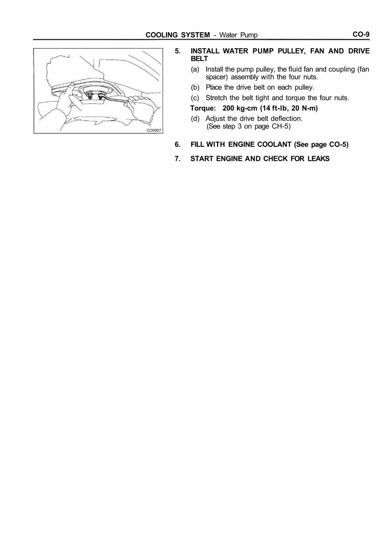
5. INSTALL WATER PUMP PULLEY, FAN AND DRIVEBELT(a) Install the pump pulley, the fluid fan and coupling (fan
spacer) assembly with the four nuts.(b) Place the drive belt on each pulley.(c) Stretch the belt tight and torque the four nuts.Torque: 200 kg-cm (14 ft-lb, 20 N-m)(d) Adjust the drive belt deflection.
(See step 3 on page CH-5)
6. FILL WITH ENGINE COOLANT (See page CO-5)
7. START ENGINE AND CHECK FOR LEAKS

CO-10 COOLING SYSTEM - Thermostat
THERMOSTATREMOVAL OF THERMOSTAT1. DRAIN ENGINE COOLANT (See page CO-5)
2. REMOVE WATER INLETRemove the three bolts and water inlet from the water inlethousing.
3. REMOVE THERMOSTAT
INSPECTION OF THERMOSTATINSPECT THERMOSTAT
HINT: The thermostat is numbered with the valve open-ing temperature.
(a) Immerse the thermostat in water and gradually heatthe water.
(b) Check the valve opening temperature.Valve opening temperature: 7 4 - 7 8 X (165-172°F)If the valve opening temperature is not as specified, replacethe thermostat.
(c) Check the valve lift.Valve lift: 10 mm (0.39 in.) or more at 90°C (194°F)If the valve lift is not as specified, replace the thermostat.(d) Check that the valve spring is tight when the thermo-
stat is fully closed.If necessary, replace the thermostat.
CO0948
C00941
CO0929
Valve LiftCO0949

CO-11COOLING SYSTEM - Thermostat
INSTALLATION OF THERMOSTAT1. PLACE THERMOSTAT IN CYLINDER BLOCK
(a) Install a new gasket to the thermostat.(b) Install the thermostat with the jiggle valve upward.
2. INSTALL WATER INLET TO CYLINDER BLOCKInstall the water inlet with the three bolts.Torque: 200 kg-cm (14 ft-lb, 20 N-m)NOTICE: Torque the two upper bolts first.
3. FILL WITH ENGINE COOLANT (See page CO-5)
4. START ENGINE AND CHECK FOR LEAKS

CO-12 COOLING SYSTEM Radiator
RADIATORCLEANING OF RADIATOR
Using water or a steam cleaner, remove any mud and dirtfrom the radiator core.NOTICE: If using a high pressure type cleaner, becareful not to deform the fins of the radiator core. Ifthe cleaner nozzle pressure is 30-35 kg/cm2(427-498psi, 2,942-3,432 kPa), keep a distance of at least40-50 cm (15.75-19.69 in.) between the radiator coreand cleaner nozzle.
INSPECTION OF RADIATOR1. INSPECT RADIATOR CAP
Using a radiator cap tester, pump the tester and measurethe relief valve opening pressure.Standard opening pressure:
0.75-1.05 kg/cm2 (10.7-14.9 psi, 74-103 kPa)Minimum opening pressure:
0.6 kg/cm2 (8.5 psi, 59 kPa)If the opening pressure is less than minimum, replace theradiator cap.
2. INSPECT COOLING SYSTEM FOR LEAKS(a) Fill the radiator with coolant and attach a radiator cap
tester.(b) Warm up the engine.(c) Pump it to 1.2 kg/cm2 (17.1 psi, 118 kPa), check that
pressure does not drop.If the pressure drops, check for leaks the hoses, radiator orwater pump. If no external leaks are found, check the heatercore, cylinder block and head.
Radiator Cap Tester
Radiator Cap
Radiator Cap Tester

LU-1
LUBRICATION SYSTEMPage
DESCRIPTION LU-2TROUBLESHOOTING LU-4OIL PRESSURE CHECK LU-5REPLACEMENT OF ENGINE OIL AND
OIL FILTER LU-6OILPUMP LU-8OIL COOLER, RELIEF VALVE AND
CHECK VALVE LU-15OIL NOZZLES AND CHECK VALVES LU-20
LU-2 LUBRICATION SYSTEM - Description
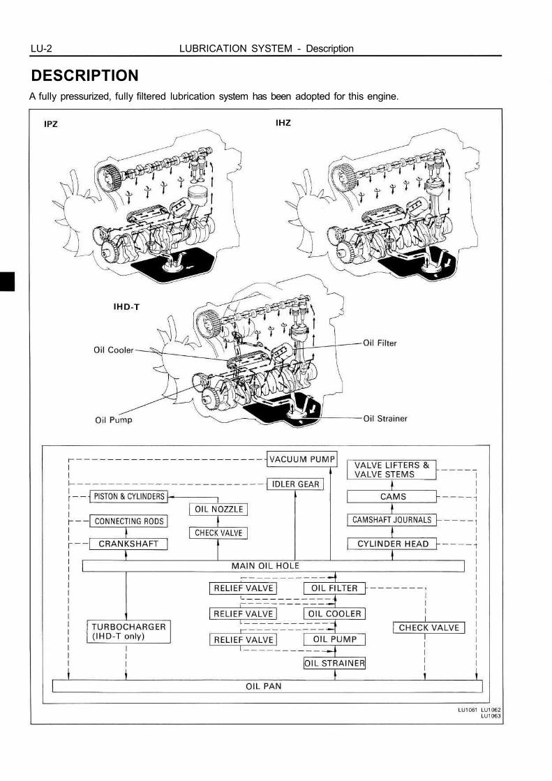
DESCRIPTIONA fully pressurized, fully filtered lubrication system has been adopted for this engine.

LUBRICATION SYSTEM Description LU-3
A pressure feeding lubrication system has beenadopted to supply oil to the moving parts of thisengine. The lubrication system consists of an oilpan, oil pump, oil filter and other external partswhich supply oil to the moving parts in the engineblock. The oil circuit is shown in the illustration atthe top of the previous page. Oil from the oil pan ispumped up by the oil pump. After it passes throughthe oil filter, it is fed through the various oil holes inthe crankshaft and cylinder block. After passingthrough the cylinder block and performing its lubri-cating function, the oil is returned by gravity to theoil pan. A dipstick on the center left side of thecylinder block is provided to check the oil level.
OIL PUMPThe oil pump pumps up oil from the oil pan and
sends it under pressure to the various parts of theengine. An oil strainer is mounted in front of theinlet to the oil pump to remove impurities. The oilpump itself is a trochoid type pump, which uses adrive rotor and driven rotor inside the pump body.When the drive rotor rotates, the driven rotor rotatesin the same direction. The axis of the driven rotorshaft is different from the center of the driven rotor,so when both rotors rotate, the space between thetwo rotors changes. Oil is drawn in when the spacewidens and is discharged when the space becomesnarrow.
OIL PRESSURE REGULATOR (RELIEF VALVE)At high engine speeds, the oil pump supplies
more oil to each part that is necessary. For thisreason, an oil pressure regulator which works toprevent oversupply of oil is installed on the oilpump. During normal oil supply, a coil spring andvalve keep the by-pass closed, but when too muchoil is being supplied, the pressure becomes ex-tremely high, overpowering the force Of the springand opening the valves. This allows the excess oilto flow through the valve and return to the inlet ofthe oil pump.
OIL FILTERThe oil filter is a full flow type filter with a built-in
paper filter element. Particles of metal from wear,airborn dirt, carbon and other impurities can get inthe oil during use and could cause accelerated wearor siezing if allowed to circulate through the engine.The oil filter, integrated into the oil line, removesthese impurities as the oil passes through it. Thefilter is mounted outside the engine to simplifyreplacement of the filter element. A relief valve isalso included ahead of the filter element to relievethe high oil pressure in case the filter elementbecomes clogged with impurities. The relief valveopens when the oil pressure overpowers the forceof the spring. Oil passing through the relief valveby-passes the oil filter and flows directly into themain oil hole in the engine.

LU-4 LUBRICATION SYSTEM - Troubleshooting
TROUBLESHOOTING
•

LUBRICATION SYSTEM Oil Pressure Check LU-5
OIL PRESSURE CHECK1. CHECK ENGINE OIL QUALITY
Check the oil for deterioration, entry of water, discoloring orthinning.If the quality is poor, replace the oil.Use API grade CD or better and recommended viscosity oil.(Europe)Use API grade CC, CD or better and recommended viscos-ity oil. (Others)
2. CHECK ENGINE OIL LEVELThe oil level should be between the "L" and "F" marks onthe dipstick.If low, check for leakage and add oil up to "F" mark.NOTICE: Do not fill with engine oil above the "F"mark.
3. REMOVE OIL PRESSURE SENDER GAUGE
4. INSTALL OIL PRESSURE GAUGE
5. WARM UP ENGINEAllow the engine to reach normal operating temperature.
6. CHECK OIL PRESSUREOil pressure:
At idling 0.3 kg/cm2 (4.3 psi, 29 kPa)or more
At 3,000 rpm 2.5 kg/cm2 (36 psi, 245 kPa)or more
7. REMOVE OIL PRESSURE GAUGE
8. REINSTALL OIL PRESSURE SENDER GAUGE
9. START ENGINE AND CHECK FOR LEAKS

LU-6 LUBRICATION SYSTEM - Replacement of Engine Oil and Oil Filter
REPLACEMENT OF ENGINE OILAND OIL FILTER
NOTICE:• Prolonged and repeated contact with mineral oil
will result in the removal of natural fats from theskin, leading to dryness, irritation and dermatitis. Inaddition, used engine oil contains potentially harm-ful contaminants which may cause skin cancer.Adequate means of skin protection and washingfacilities should be provided.
• Care should be taken, therefore, when changingengine oil, to minimize the frequency and length oftime your skin is exposed to used engine oil. Protec-tive clothing and gloves, that cannot be penetratedby oil, should be worn. The skin should be tho-rougthly washed with soap and water, or use wa-terless hand cleaner, to remove any used engine oil.Do not use gasoline, thinners, or solvents.
• In order to preserve the environment, used oil and usedoil filters must be disposed of only at designated dis-posal sites.
1. DRAIN ENGINE OIL(a) Remove the oil filler cap.(b) Remove the oil drain plug, and drain the oil into a
container.
2. REPLACE OIL FILTER(a) Using SST, remove the oil filter.SST 09228-10001
(b) Clean and check the oil filter installation surface.

LUBRICATION SYSTEM Replacement of Engine Oil and Oil Filter LU-7
(c) Apply clean engine oil to the gasket of a new oil filter.
(d) Lightly screw the oil filter into place, and tighten ituntil the gasket contacts the seat.
(e) Using SST, tighten it additional 3/4 turn.SST 09228-10001
3. FILL WITH ENGINE OIL(a) Clean and install the oil drain plug with a new gasket.Torque: 250 kg-cm (18 ft-lb, 25 N-m)(b) Fill with new engine oil (API grade CC (ex. Europe),
CD or better and recommended viscosity oil).Capacity (PZJ70, 73. 75):
Drain and refillw/ Oil filter change
9.0 liters (9.5 US qts, 7.9 Imp. qts)w/o Oil filter change
7.7 liters (8.1 US qts, 6.8 Imp. qts)Dry fill 9.3 liters (9.8 US qts, 8.2 Imp. qts)
Capacity (HZJ70, 73, 75):Drain and refill
w/ Oil filter change9.5 liters (10.0 US qts, 8.4 Imp. qts)
w/o Oil filter change8.2 liters (8.7 US qts, 7.2 Imp. qts)
Dry fill 9.8 liters (10.4 US qts, 8.6 Imp. qts)Capacity (HZJ80 and HDJ80):
Drain and refillw/ Oil filter change
9.3 liters (9.8 US qts, 8.1 Imp. qts)w/o Oil filter change
8.0 liters (8.5 US qts, 7.0 Imp. qts)Dry fill 9.6 liters (10.1 US qts, 8.4 Imp. qts)
Capacity (HZB30 and HDB30):Drain and refill
w/ Oil filter change9.8 liters (10.4 US qts, 8.6 Imp. qts)
w/o Oil filter change8.5 liters (9.0 US qts, 7.5 Imp. qts)
Dry fill 10.1 liters (10.7 US qts, 8.9 Imp. qts)
(c) Reinstall the oil filler cap.
4. START ENGINE AND CHECK FOR LEAKS
5. RECHECK ENGINE OIL LEVEL (See page LU-5)

LU-8 LUBRICATION SYSTEM - Oil Pump
OIL PUMPCOMPONENT

LUBRICATION SYSTEM - Oil Pump LU-9
REMOVAL OF OIL PUMP(See page LU-8)
HINT: When repairing the oil pump, the oil pan andstrainer should be removed and cleaned.
1. DRAIN ENGINE COOLANT (See page CO-4)
2. DRAIN ENGINE OIL (See page LU-6)
3. REMOVE TIMING GEARS(See steps 1 to 12 on pages EM-43 to 45)
4. REMOVE OIL PAN(a) Remove the twenty-three bolts (1PZ) or twenty-
seven bolts (1 HZ and IHD-T) and three nuts.
(b) Insert the blade of SST between the cylinder blockand oil pan, cut off applied sealer and remove the oilpan.
SST 09032-001 00NOTICE:• Do not use SST for the timing gear case side and
rear oil seal retainer.• Be careful not to damage the oil pan flange.
5. REMOVE OIL STRAINERRemove the two bolts, two nuts, oil strainer and gasket.
6. REMOVE OIL PUMP (TIMING GEAR CASE)(a) Before removing the two nuts holding the timing gear
case to the injection pump, check if the injectionpump period lines are aligned.
If not, place new matchmarks for reinstallation.(b) Remove the two nuts.

LU-10 LUBRICATION SYSTEM - Oil Pump
(c) Remove the seven bolts, timing gear case and gasket.
(d) Using a plastic-faced hammer, lightly tap out thetiming gear case.
(e) Remove the gasket.
DISASSEMBLY OF OIL PUMP1. REMOVE DRIVEN ROTOR
2. REMOVE RELIEF VALVERemove the plug, gasket, spring and relief valve.

LUBRICATION SYSTEM - Oil Pump LU-11
INSPECTION OF OIL PUMP1. INSPECT RELIEF VALVE
Coat the valve with engine oil and check that it fallssmoothly into the valve hole by its own weight.If it does not, replace the relief valve. If necessary, replacethe oil pump assembly.
2. INSPECT DRIVE AND DRIVEN ROTORS
A. Inspect rotor body clearanceUsing a thickness gauge, measure the clearance betweenthe driven rotor and body.Standard body clearance: 0.10-0.17 mm
(0.039-0.0067 in.)Maximum body clearance: 0.20 mm (0.0079 in.)If the body clearance is greater than maximum, replace theoil pump assembly.
B. Inspect rotor side clearanceUsing a thickness gauge and precision straight edge,measure the clearance between the rotors and precisionstraight edge.Standard side clearance: 0.03-0.09 mm
(0.0012-0.0035 in.)Maximum side clearance: 0.15 mm (0.0059 in.)If the side clearance is greater than maximum, replace theoil pump assembly.
C. Inspect rotor tip clearanceUsing a thickness gauge, measure the clearance betweenthe drive and driven rotors.Standard tip clearance: 0.08 — 0.16 mm
(0.0031 - 0.0063 in.)Maximum tip clearance: 0.21 mm (0.0083 in.)If the tip clearance is greater than maximum, replace the oilpump assembly.

LU-12 LUBRICATION SYSTEM - Oil Pump
ASSEMBLY OF OIL PUMP(See page LU-8)
1. INSTALL DRIVEN ROTOR
2. INSTALL RELIEF VALVE(a) Insert the relief valve and spring into the installation
hole of the timing gear case.(b) Install a new gasket and the plug.Torque: 425 kg-cm (31 ft-lb, 42 N-m)
INSTALLATION OF OIL PUMP(See page LU-8)
1. INSTALL OIL PUMP (TIMING GEAR CASE)(a) Remove any old packing (FIPG) material and be
careful not to drop any oil on the contact surfaces ofthe timing gear case and cylinder block.• Using a razor blade and gasket scraper, remove all
the old packing (FIPG) material from the gasketsurfaces and sealing groove.
• Thoroughly clean all components to remove all theloose material.
• Using a non-residue solvent, clean both sealingsurfaces.
(b) Apply seal packing to the timing gear case as shownin the illustration.
Seal packing: Part No.08826-00080 or equivalent• Install a nozzle that has been cut to a 2 - 3 mm
(0.08-0.12 in.) opening.• Parts must be assembled within 5 minutes of appli-
cation. Otherwise the material must be removedand reapplied.
• Immediately remove nozzle from the tube and rein-stall cap.
(c) Place a new gasket into the groove of the timing gearcase as shown in the illustration.
LUBRICATION SYSTEM - Oil Pump LU-13
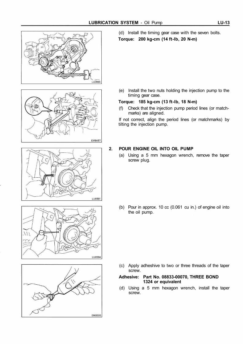
(d) Install the timing gear case with the seven bolts.Torque: 200 kg-cm (14 ft-lb, 20 N-m)
(e) Install the two nuts holding the injection pump to thetiming gear case.
Torque: 185 kg-cm (13 ft-lb, 18 N-m)(f) Check that the injection pump period lines (or match-
marks) are aligned.If not correct, align the period lines (or matchmarks) bytilting the injection pump.
2. POUR ENGINE OIL INTO OIL PUMP(a) Using a 5 mm hexagon wrench, remove the taper
screw plug.
(b) Pour in approx. 10 cc (0.061 cu in.) of engine oil intothe oil pump.
(c) Apply adheshive to two or three threads of the taperscrew.
Adhesive: Part No. 08833-00070, THREE BOND1324 or equivalent
(d) Using a 5 mm hexagon wrench, install the taperscrew.

LU-14 LUBRICATION SYSTEM - Oil Pump
3. INSTALL OIL STRAINERInstall a new gasket and the oil strainer with the two boltsand two nuts.Torque: 90 kg-cm (78 in.-lb, 8.8 Nm)
4. INSTALL OIL PAN(a) Remove any old packing (FIPG) material and be
careful not to drop any oil on the contact surfaces ofthe oil pan and cylinder block.• Using a razor blade and gasket scraper, remove all
the old packing (FIPG) material from the gasketsurfaces and sealing groove.
• Thoroughly clean all components to remove all theloose material.
• Using a non-residue solvent, clean both sealingsurfaces.
NOTICE: Do not use a solvent which will affect thepainted surfaces.(b) Apply seal packing to the oil pan as shown in the
illustration.Seal packing: Part No.08826-00080 or equivalent
• Install a nozzle that has been cut to a 5 mm (0.20in.) opening.
• Parts must be assembled within 5 minutes of appli-cation. Otherwise the material must be removedand reapplied. *
• Immediately remove nozzle from the tube and rein-stall cap.
(c) Install the oil pan with the twenty-three bolts (1 PZ) ortwenty-seven bolts (1 HZ and 1 HD-T) and three nuts.
Torque: 100 kg-cm (7 ft-lb, 10 Nm)
5. INSTALL TIMING GEARS
(See steps 2 to 12 on pages EM-50 to 53)
6. FILL WITH ENGINE OIL (See page LU-7)
7. FILL WITH ENGINE COOLANT (See page CO-5)
8. START ENGINE AND CHECK FOR LEAKS

LUBRICATION SYSTEM Oil Cooler. Relief Valve and Check Valve LU-15
OIL COOLER, RELIEF VALVE ANDCHECK VALVECOMPONENTS

LU-16 LUBRICATION SYSTEM - Oil Cooler, Relief Valve and Check Valve
REMOVAL OF OIL COOLER, RELIEF VALVEAND CHECK VALVE(See page LU-15)
1. DRAIN ENGINE COOLANT (See page CO-4)
2. REMOVE OIL FILTER (Seepage LU-6)3. REMOVE INJECTION PUMP
(See page FU-27)
4. REMOVE OIL DIPSTICK AND GUIDE(a) Remove the two bolts, oil dipstick and guide.(b) Remove the oil ring from the oil dipstick guide.
5. REMOVE OIL COOLER AND OIL COOLER COVERASSEMBLYRemove the thirteen bolts, two nuts, oil cooler and oilcooler assembly and gasket.
6. SEPARATE OIL COOLER AND OIL COOLER COVERRemove the four nuts, oil cooler and two gaskets from theoil cooler cover.
7. REMOVE RELIEF VALVERemove the relief valve and gasket.
8. REMOVE CHECK VALVERemove the check valve and gasket.

LUBRICATION SYSTEM Oil Cooler, Relief Valve and Check Valve LU-17
9. REMOVE ENGINE DRAIN COCK
INSPECTION OF OIL COOLER, RELIEF VALVEAND CHECK VALVE1. INSPECT RELIEF VALVE
Push the valve with a wooden stick to check if it is stuck.If stuck, replace the relief valve.
2. INSPECT CHECK VALVEPush the valve with a wooden stick to check if it is stuck.If stuck, replace the check valve.
3. INSPECT OIL COOLERCheck the oil cooler for damage or clogging.If necessary, replace the oil cooler.

LU-18 LUBRICATION SYSTEM - Oil Cooler, Relief Valve and Check Valve
INSTALLATION OF OIL COOLER, RELIEFVALVE AND CHECK VALVE(See page LU-15)
1. INSTALL ENGINE DRAIN COCK(a) Apply adhesive to two or three threads of the drain
cock.Adhesive: Part No. 08833-00070, THREE BOND 1324
or equivalent
(b) Install and torque the drain cock as shown.Torque: 200 kg-cm (14 ft-lb, 20 Nm)
2. INSTALL CHECK VALVEInstall the check valve with a new gasket.Torque: 275 kg-cm (20 ft-lb, 27 N-m)
3. INSTALL RELIEF VALVEInstall the relief valve with a new gasket.Torque: 400 kg-cm (29 ft-lb, 39 Nm)
4. ASSEMBLE OIL COOLER AND OIL COOLER COVERInstall two new gaskets and the oil cooler to the oil coolercover with the four nuts.Torque: 200 kg-cm (14 ft-lb, 20 N-m)
LUBRICATION SYSTEM - Oil Cooler, Relief Valve and Check Valve LU-19
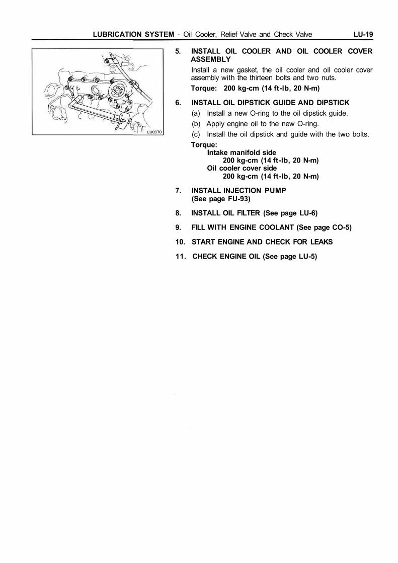
5. INSTALL OIL COOLER AND OIL COOLER COVERASSEMBLYInstall a new gasket, the oil cooler and oil cooler coverassembly with the thirteen bolts and two nuts.Torque: 200 kg-cm (14 ft-lb, 20 N-m)
6. INSTALL OIL DIPSTICK GUIDE AND DIPSTICK(a) Install a new O-ring to the oil dipstick guide.(b) Apply engine oil to the new O-ring.(c) Install the oil dipstick and guide with the two bolts.Torque:
Intake manifold side200 kg-cm (14 ft-lb, 20 N-m)
Oil cooler cover side200 kg-cm (14 ft-lb, 20 N-m)
7. INSTALL INJECTION PUMP(See page FU-93)
8. INSTALL OIL FILTER (See page LU-6)
9. FILL WITH ENGINE COOLANT (See page CO-5)
10. START ENGINE AND CHECK FOR LEAKS
11. CHECK ENGINE OIL (See page LU-5)

LU-20 LUBRICATION SYSTEM - Oil Nozzles and Check Valves
OIL NOZZLES AND CHECK VALVESCOMPONENTS
REMOVAL OF OIL NOZZLES AND CHECKVALVES1. DRAIN ENGINE OIL (See page LU-6)
2. REMOVE OIL PAN(See step 4 on page LU-9)
3. REMOVE CHECK VALVE AND OIL NOZZLESRemove the five (1 PZ) or six (1 HZ and 1HD-T) checkvalves and oil nozzles.

LUBRICATION SYSTEM - Oil Nozzles and Check Valves LU-21
INSPECTION OF OIL NOZZLES AND CHECKVALVES1. INSPECT CHECK VALVES
Push the valve with a wooden stick to check if it is stuck.If stuck, replace the check valve.
2. INSPECT OIL NOZZLESCheck the oil nozzles for damage or clogging.If necessary, replace the oil nozzle.
INSTALLATION OF OIL NOZZLES AND CHECKVALVES(See page LU-20)
1. INSTALL OIL NOZZLES AND CHECK VALVES(a) Align the pin of the oil nozzle with the pin hole of the
cylinder block.(b) Install the oil nozzle with the check valve. Install the
five (1PZ) or six (1HZ and 1HD-T) oil nozzles andcheck valves.
Torque: 275 kg-cm (20 ft-lb, 27 Nm)
2. INSTALL OIL PAN
(See step 4 on page LU-14)
3. FILL WITH ENGINE OIL (See page LU-7)
4. START ENGINE AND CHECK FOR LEAKS