co capture study in advanced integrated gasification
TRANSCRIPT

HAL Id: hal-00498953https://hal.archives-ouvertes.fr/hal-00498953
Submitted on 9 Jul 2010
HAL is a multi-disciplinary open accessarchive for the deposit and dissemination of sci-entific research documents, whether they are pub-lished or not. The documents may come fromteaching and research institutions in France orabroad, or from public or private research centers.
L’archive ouverte pluridisciplinaire HAL, estdestinée au dépôt et à la diffusion de documentsscientifiques de niveau recherche, publiés ou non,émanant des établissements d’enseignement et derecherche français ou étrangers, des laboratoirespublics ou privés.
CO capture study in advanced Integrated GasificationCombined Cycle
Mohamed Kanniche, Chakib Bouallou
To cite this version:Mohamed Kanniche, Chakib Bouallou. CO capture study in advanced Integrated Gasifi-cation Combined Cycle. Applied Thermal Engineering, Elsevier, 2007, 27 (16), pp.2693.�10.1016/j.applthermaleng.2007.04.007�. �hal-00498953�

Accepted Manuscript
CO2 capture study in advanced Integrated Gasification Combined Cycle
Mohamed Kanniche, Chakib Bouallou
PII: S1359-4311(07)00133-0
DOI: 10.1016/j.applthermaleng.2007.04.007
Reference: ATE 2155
To appear in: Applied Thermal Engineering
Received Date: 13 December 2006
Revised Date: 21 March 2007
Accepted Date: 7 April 2007
Please cite this article as: M. Kanniche, C. Bouallou, CO2 capture study in advanced Integrated Gasification
Combined Cycle, Applied Thermal Engineering (2007), doi: 10.1016/j.applthermaleng.2007.04.007
This is a PDF file of an unedited manuscript that has been accepted for publication. As a service to our customers
we are providing this early version of the manuscript. The manuscript will undergo copyediting, typesetting, and
review of the resulting proof before it is published in its final form. Please note that during the production process
errors may be discovered which could affect the content, and all legal disclaimers that apply to the journal pertain.

ACCEPTED MANUSCRIPT
� � �1
CO2 capture study in advanced Integrated Gasification Combined Cycle
Mohamed Kanniche1, Chakib Bouallou2*
(1) EDF, Research and Development Division, Fluid Mechanics Energies and Environment
Department, 6 quai Watier 78401 Chatou cedex, France. Tel : 33 1 30 87 71 08,
Email: [email protected]
(2) Centre Énergétique et Procédés (CEP), Ecole Nationale Supérieure des Mines de Paris,
60, Boulevard Saint Michel, 75006 Paris, France. Tel: 33 1 40 51 91 11,
Email: [email protected]
* corresponding author

ACCEPTED MANUSCRIPT
� � �2
Abstract
This paper presents the results of technical and economic studies in order to evaluate, in
the French context, the future production cost of electricity from IGCC coal power plants with
CO2 capture and the resulting cost per tonne of CO2 avoided. The economic evaluation shows
that the total cost of base load electricity produced in France by coal IGCC power plants with
CO2 capture could be increased by 39% for ‘classical’ IGCC and 28% for ‘advanced’ IGCC.
The cost per tonne of avoided CO2 is lower by 18% in ‘advanced’ IGCC relatively to
‘classical’ IGCC. The approach aimed to be as realistic as possible for the evaluation of the
energy penalty due to the integration of CO2 capture in IGCC power plants. Concerning the
CO2 capture, six physical and chemical absorption processes were modeled with the Aspen
Plus™ software. After a selection based on energy performance three processes were selected
and studied in detail: two physical processes based on methanol and Selexol™ solvents, and a
chemical process using activated MDEA. For ‘advanced’ IGCC operating at high-pressure,
only one physical process is assessed: methanol.
Keywords: CO2 capture, coal, slurry, methanol, MDEA, power plant, avoided CO2

ACCEPTED MANUSCRIPT
� � �3
Nomenclature
IGCC: Integrated gasification combined cycle
ASU: Air separation unit
LHV: low heating value
MEA: methylethanolamine
MDEA: methyldiethanolamine
A-MDEA: activated methyldiethanolamine
NMP: N-methyl-pyrrolidone
AMP: amine 2-amino-2-methyl-1-propanol
Selexol™: process using dimethyl ether of polyethylene glycol (DMPEG)
Syngas: synthetic gas produced by the gasification

ACCEPTED MANUSCRIPT
� � �4
1. Introduction
To meet the growing world demand for energy, which will be driven increasingly by the
developing countries, recourse to fossil fuels will remain dominant at least for the first half of
the 21st century. The tendency for CO2 emissions to increase will therefore be considerable,
though the objective should be to stabilize the concentration of CO2 in the atmosphere to an
acceptable level: for example 550 ppm in 2100. This objective cannot be achieved by simply
stabilizing the quantities of CO2 discharged into the atmosphere, but by reducing them by at
least a factor of 2 or 3 as a world average [1]. In addition to the use of nuclear power and
renewable energy, the need to reduce CO2 emissions substantially could therefore lead to the
capture and storage of the CO2 emitted by large combustion plants in underground geological
formations (depleted hydrocarbon reservoirs or deep saline aquifers) as it does not seem
possible to envisage storage of CO2 in the ocean in the near future.
Integrated Gasification Combined Cycles (IGCC) is the type of power technology
particularly favorable for carbon dioxide capture as this latter can be removed at a convenient
stage of the process where its partial pressure is high [2]. The various options analyzed in the
literature concerning this integration are described in [3], [4] and [5]: pre-combustion with a
modification of the power station structure; post-combustion with a low pressure separation
before the stack in an “end of pipe” separation process; decarbonization of the fuel by
producing hydrogen, methanol or ammonia; modified cycle as oxy-combustion O2/CO2 cycle.
The CO2 removal requires the addition of two main units: a CO shift conversion unit

ACCEPTED MANUSCRIPT
� � �5
downstream from the gas dedusting system and a CO2 separation and compression unit
meeting the transport conditions.
This paper presents a summary of the results of technical and economic studies conducted
by EDF-R&D in collaboration with various organizations: Ecole des Mines de Paris, Technip
and UOP for the CO2 capture processes at the power plant, with the financial support of
ADEME, the French agency for environment and energy management, and with Géostock and
Tractebel for the CO2 transport and storage. The aim was to evaluate, in the French context,
the levelized cost of electricity from coal with and without CO2 capture and storage and the
cost per tonne of CO2 avoided. The coal option was chosen on account of the large proven
reserves of this fossil fuel (2 to 3 centuries at present consumption rate) and oxygen blown
IGCC was selected as it seems to be the best alternative for electricity generation from coal in
the medium/long term [6], [7] and [8], showing some specific advantages:
- IGCC is a clean coal technology that today offers significant reduction in air-pollutant
emissions,
- In this process, coal reacts under pressure with oxygen and steam in the gasifier
producing a syngas which can be shifted to CO2/H
2 mixture in a catalytic reactor leading
to a high partial pressure of CO2 which is favorable for its capture,
- After CO2 capture, the fuel gas is essentially hydrogen which can be used to generate
electricity in a combined cycle or, in the future, in fuel cells in order to increase the
overall efficiency, and
ACCEPTED MANUSCRIPT
� � �6
- IGCC may offer opportunities to produce power as well as synthetic fuels and
chemicals.
We focus in this paper on a CO2 separation in order to integrate this option into the power
plant cycle, upstream from the gas turbine.
2. Capturing CO2 at the power plant
EDF-R&D has carried out an investigation, in close collaboration with the Ecole des
Mines de Paris, in order to select the best processes for collecting CO2 to be integrated into an
IGCC power plant and to calculate its impact on efficiency. Moreover, with the assistance of
the Technip Company and UOP, the investment costs associated with the new equipment have
been estimated and the total cost per kWh (with and without CO2 capture) has been evaluated.
2.1. Capture technology
Various processes may be envisaged for separating the CO2: chemical or physical
absorption (or an association of both), adsorption onto solids, separation by membranes and
cryogenic separation. Obviously these processes are not all equivalent, nor all at the same
stage of development. Cryogenic separation needs too much energy and appears to be too
expensive; separation by membranes is attractive (a principle similar to filtration) but today
the ‘right’ membranes required are under development and do not yet exist for an industrial
scale; adsorption onto a solid does not seem very suitable for processing huge volumes of gas.
In the end, only physical and chemical (or mixed) absorption methods seem suitable for large

ACCEPTED MANUSCRIPT
� � �7
power plants, but the choice of the ‘best’ solvent is still a very open question. A typical
absorption process is shown in Figure 1: the gas to be treated is injected at the bottom of the
absorption column after it is cooled at a first step in a heat exchanger which heats the treated
gas exiting the column and depending on the process type (e.g. for methanol, NMP and
Selexol™ processes) in a second step using a refrigeration system. The solvent is injected at
the top of the absorption column to absorb the CO2 from the gas. The rich solvent is then
heated by exchanging heat with the lean solvent coming from the desorption column. The
solvent is regenerated in the desorption column using low-pressure steam condensation in the
reboiler.
CO2 separation processes with chemical solvents (alkanolamines) have been industrialized
since the seventies and licensors have been looking these last few years at specific solvent
formulations: primary or secondary amines and anti-corrosion additives, tertiary amines with
promoters or activators and with antifoaming additives. Mixing of chemical solvents, such as
tertiary amines and a relatively small amount of the primary amine, aims to combine the
advantages of the two solvents. The target of such mixed chemical solvents is to achieve a
better absorption capacity, to avoid solvent degradation and to limit corrosion. Physical
solvents (methanol, propylene carbonate, n-methyl-pyrrolidone (NMP), Dimethylether of
polyethylene glycol (Selexol™)) are known for their chemical stability and for a non-induced
corrosion effect. Moreover, their high absorption capacities make them interesting for bulk
removal. However, methanol needs low operating temperatures because of its higher volatility.
The high volatility is a disadvantage with regard to the potential solvent losses. Even if the
process streams are chilled to -30°C, it is necessary, before the transport and the storage of the
ACCEPTED MANUSCRIPT
� � �8
CO2, to add to the CO2 compression unit a wash water column to capture methanol with water
from the CO2 stream (Figure 2). For the CO2 transportation, the water content should not
exceed 20 ppmm to avoid corrosion problems. This threshold value was specified by gas
transportation experts of Tractebel licensed by EDF for CO2 transportation. For this purpose a
dehydration system based on tri-ethylene-glycol (TEG) is added in the compression unit
(Figure 2). For methanol recovery from water a distillation column is then added to the CO2
capture unit (Figure 3). NMP also requires a refrigeration system to meet relatively low
temperatures. The refrigeration system uses electricity for the compression of the refrigeration
media, which means a higher energy penalty for the process than cooling water.
Mixing the chemical and physical solvents (hybrid solvent) allows an increased CO2
absorption capacity compared to chemical solvent alone. The solubility of carbon dioxide in
primary or secondary amines is improved by the addition of NMP, [9]. The solubility of
carbon dioxide is compared in a mixture of methyldiethanolamine, MDEA and methanol, and
in methanol, [10]. The physical solvent polarity and permitivity are significant on the
ionization of the species and on reaction kinetics. However, the kinetics of CO2 absorption by
physical solvents and amines, in aqueous solution form or not, are still unknown.
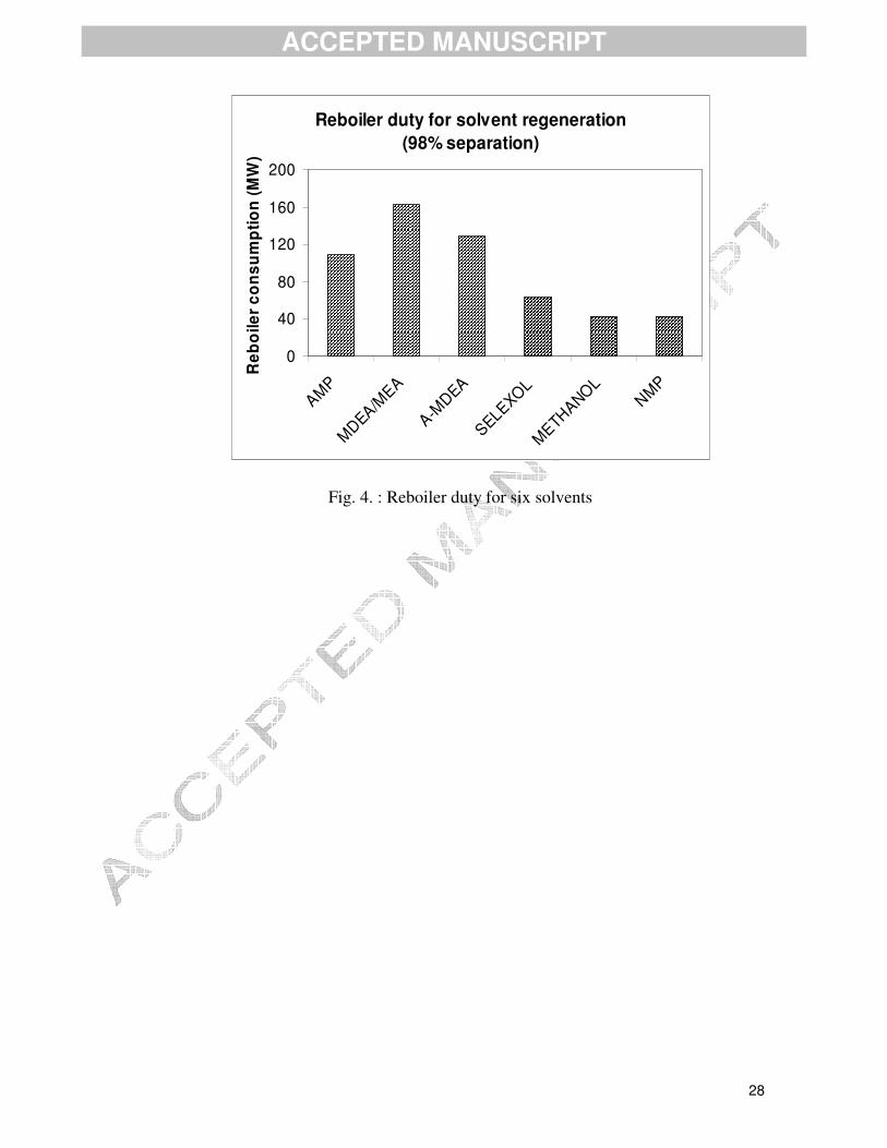
In this work, six processes are evaluated as stand alone units, fed with the same synthesis
gas (50 kg/s and 24 bar): three physical processes, methanol, n-methyl-pyrrolidone (NMP),
Selexol, and three chemical processes, a sterically hindered amine 2-amino-2-methyl-1-
propanol (AMP), activated methyldiethanolamine (A-MDEA) and a mixture of
methyldiethanolamine and monoethanolamine in aqueous solution (MDEA 25 mol % /MEA 5
ACCEPTED MANUSCRIPT
� � �9
mol %). We considered the electrical and thermal consumption for the CO2 capture. The
electrical consumption is similar for the six processes, while thermal consumption is rather
high for chemical processes as can be seen in Figure 4. Then three processes are selected for
the integration in the global IGCC system. These processes are: methanol, Selexol and
activated MDEA. The activated MDEA process was integrated into the IGCC and added to the
comparison study in order to evaluate a chemical process relative to the two physical ones.
Particular attention was paid to thermodynamic models. A simple equation of state,
Redlich Kwong Soave, is chosen for the synthesis gas and the flue gas, but the thermodynamic
model Steamnbs [11] (based on the 1984 NBS/NRC steam table correlation for
thermodynamic properties and International Association for Properties of Steam IAPS for the
transport properties) is used for pure water and steam, and the Electrolyte Non Random Two
Liquid model for the aqueous electrolyte system. The Redlich Kwong Soave equation of state,
with the Holderbaum and Gmehling mixing rule [12] is chosen for the CO2 capture process.
The calculation of the activity coefficient model is done by Uniquac for which the interaction
parameters are fitted on measured data from the literature [13]. The CO2 methanol
equilibrium, [13] and [14], was studied and modeled to optimize the methanol loss calculation
in the CO2 stream leaving the desorption column. The simulation of the absorption and
desorption is performed with a rigorous distillation model.
Moreover, an optimized case has been studied, which consists in the adjustment of the
thermodynamic parameters and in improvement of the capture process. Hydrogen co-
absorption in methanol has been studied in order to improve the calculation of the hydrogen

ACCEPTED MANUSCRIPT
� � �10
losses by absorption in the solvent. The hydrogen/methanol binary interactions were measured
and the interaction parameters of the thermodynamic model (Uniquac) were calculated. The
methanol flow rate is slightly reduced when the H2-methanol binary interaction parameter is
taken into account, leading to a reduced consumption of steam in the thermal regeneration.
The separation process flow diagram has been improved by the addition of two flash drums in
order to reduce the CO2 compression power.
Finally, the solvent flow rate is optimized to perform the CO2 separation with a minimum
of steam consumption in the thermal regeneration. The solvent regeneration column is
calculated for each case, as a residual CO2 concentration is determined in the lean solvent in
order to be compatible with the required CO2 purity in the top of the absorption column. A
low operating temperature of –30 °C is chosen for the methanol in order to minimize the
solvent losses and to maximize the carbon dioxide solubility.
2.2. Integration to IGCC systems
For a ‘classical’ IGCC power plant, the study was based on the Puertollano [15] scheme
operating at 27 bars and where 100% of air feeding the air separation unit (ASU) producing
oxygen and nitrogen is extracted from the gas turbine (full integration). As the coal is injected
in dry form using pure nitrogen (given by the ASU) as the transportation medium from coal
grinder to the gasifier, the necessary steam for the gasification is extracted from the combined
cycle. The CO2 separation unit was integrated downstream from the existing desulphuration
unit, and after a CO shift conversion unit (Figure 5). The integration of the three selected

ACCEPTED MANUSCRIPT
� � �11
processes was performed as realistically as possible: avoiding great modifications of the
existing IGCC, conserving the existing sulphur removal unit, adding a shift conversion in the
appropriate part of the system to conserve equilibrated H2S/CO2 acid gas for the Claus plant
(pure sulphur production), fully integrating the combined cycle and the shift conversion (this
latter produces a smaller amount of Medium Pressure steam than it consumes), bleeding steam
from the appropriate part of the combined cycle, thermal balancing of the feed water flash
tank, using saturated steam instead of superheated steam for the solvent regeneration column,
adjusting thermodynamic parameters of gas/solvent binary interactions (the
hydrogen/methanol binary interactions are measured, others are taken from published
experimental data), adding steam to the gas turbine in order to ensure low NOx emission as
the synthetic gas now has hydrogen as its major component, conserving the design parameters
of both gas turbine and steam turbine. The design parameters of the gas turbine (the turbine
inlet temperature and the equivalent weight flow) and of the steam turbine (Stodola criteria)
are taken into account, and the reduction of the NOx production in the combustion chamber is
considered. Thus the choice is made to feed the gas turbine of the combined cycle with a
diluted synthesis gas, having a low heating value similar to that produced without the CO2
capture. As a consequence, a significant amount of steam is injected into the combustion
chamber. We focus on the energy consumption of CO2 capture and on the energy penalty of
optimised retrofit IGCC.
Concerning the ‘advanced’ IGCC system (Figure 6) which is fed with a mixture of coal
and water (slurry), the shift conversion is inserted immediately downstream from the
gasification system as the synthetic gas contains enough water to convert CO into CO2. The

ACCEPTED MANUSCRIPT
� � �12
coal feed in slurry form enables the gasifier to operate at high pressure, 64 bars which permits
an economy in the process volume and this high pressure is also favorable to physical
absorption (Henry law). After a gas treatment where heat is recovered to produce medium and
low-pressure steams, the CO2 and H2S are captured in the same unit. The acid gas containing
more than 25% H2S is sent to a Claus unit for sulphur recovery and the CO2 is sent to a
compression unit. The clean gas is expanded in order to recover electrical power and heated
before dilution with waste nitrogen coming from the air separation unit.
We could notice that here (see figure 6) only 50% of the air needed by the ASU is
extracted from the gas turbine; the remaining 50% is taken from ambient air using an ASU
dedicated compressor. In fact, the optimum of integration depends on the type of gas turbine
and specific studies should be performed for each gas turbine considered. Moreover, as the
gasification is fed with slurry, the synthetic gas contains a relatively high amount of CO2
compared to dry gasification. Therefore there is no more need of gas saturation with water or
steam injection in the combustion chamber to meet low level of NOx pollutant, the low
heating value (LHV) of the diluted syngas being sufficiently low.
2.3. Performance in terms of energy of CO2 capture
We have based our evaluation on the IGCC unit of Puertollano [8 ], [15] revaluated under
ISO conditions (1.013 bar, 15°C, 60% relative humidity) and using an international coal (16 %
ash, 2 % moisture and 1 % sulfur) instead of the mixture of Puertollano local coal + petroleum
coke. Under these ‘standard’ conditions, the net power of the plant is 326 MW and the LHV

ACCEPTED MANUSCRIPT
� � �13
efficiency is 44 %. Several physical and chemical absorption processes have been modeled
with Aspen Plus™ software to compare their energy performance. However, to avoid too
many power plant design modifications, the gasification pressure has been kept equal to 27
bars, although for physical solvents a higher pressure would have been more favorable. That is
why after an initial selection, three processes were finally adopted and studied in detail: a
physical absorption process by methanol, another physical absorption process, the Selexol
process, in which the solvent is based on dimethylether polyethylene glycol (DMPEG), and a
process using an activated amine-based chemical solvent, methyl-diethanolamine (MDEA).
In addition to the equipment required for CO2 separation (absorption and desorption
columns, pumps, heat exchangers, pressure reduction tanks, etc.), we also included in the
process:
- a catalytic device for conversion of the CO into CO2 ("shift conversion") upstream of the
separation in order to increase the CO2 content and thus improve the efficiency of the capture;
- a refrigeration system for the methanol process to maintain an optimum temperature of
-30°C in the absorption column and a downstream recovery system to limit losses of the
absorbent;
- a device to reduce the water content in the CO2 produced to less than 20 ppmm to prevent
acid corrosion in the transport pipes;

ACCEPTED MANUSCRIPT
� � �14
- a 150 bar CO2 compression station linked to a gas cooling system (final temperature <
40°C) in order to comply with the specifications of the CO2 transport network.
The CO2 absorption rate in the IGCC integrated methanol process has been varied from
77 to 88 mol %, with a CO conversion rate fixed at 90 mol %. Figure 7 shows that 85% CO2
recovery seems to be a good compromise: above this recovery rate, the energy penalty grows
quite steeply, while below 85% recovery rate the energy penalty decreases almost linearly. In
fact, 85% was then chosen to compare the three processes integrated into the global IGCC
system. This takes into account the efficiency of conversion of CO into CO2 (90 %) and that of
the separation of the CO2 itself (approximately 95%). The efficiency loss shown in Figure 8 is
calculated by the difference in efficiency of IGCC with and without capture divided by the
efficiency of IGCC without capture.
The power output of the gas turbine was maintained nearly constant with the CO2 capture
operation by adding enough coal flow rate to the gasifier. The auxiliary electric consumption
takes into account all the electric power needed by pumps and compressors, including the CO2
inter-cooling compressor which delivers a CO2 flux at 150 bar and 37°C, the solvent recycling
pump, and the compressor for methanol refrigeration (see Figure 9). As can be seen in Figure
9, all the solvents have almost similar consumption for the CO2 compression and for the
standard auxiliaries (such as Air Separation Units and pumps and compressors of the units
other than the CO2 capture one). However, the chemical solvent shows a higher consumption
due to the steam bleeding for solvent regeneration. This consumption was calculated by
disconnecting the steam flux going from the combined cycle to the solvent regeneration
column and calculating the difference in the power output when this flux is fully integrated.

ACCEPTED MANUSCRIPT
� � �15
Figure 8 shows the performance of the three solvents integrated into the IGCC, compared
to the IGCC without capture. The comparison of the different energy balances is presented for
85% recovery of CO2. The best energy performance is obtained with the methanol process
although the performance of the other two systems is close. The efficiency of ‘classical’ IGCC
with CO2 capture using methanol is 33.5% and is therefore 10.5 points lower than that of the
reference IGCC power plant, which represents a relative reduction of 24 %. The fact that
physical and chemical processes show similar energy performance was expected as the
‘classical’ IGCC operates at relatively low pressure (27 bars) which delivers CO2 to the
capture system at a partial pressure around 8 bars. This is the starting point of chemical
absorption saturation and the lower limit of physical absorption efficiency. With ‘advanced’
IGCC operating at a higher pressure (64 bars instead of 27 bars for ‘classical’ IGCC), the CO2
capture using a physical solvent like methanol seems to be more interesting than the same
operation in ‘classical’ IGCC because of high partial pressure of CO2 in the former case. The
efficiency loss is only 9.3 points (see Table 1) in ‘advanced’ IGCC whereas in ‘classical’
IGCC the efficiency drop is above 10 points. However, in the cases without CO2 capture
‘advanced’ IGCC has lower efficiency than ‘classical’ IGCC. This is because ‘advanced’
IGCC uses feedstock in slurry form which should contain a maximum of 64% solids otherwise
the compression operation to 64 bars could be risky because of increasing viscosity with solid
contents. Therefore there is a high amount of water to evaporate in the slurry gasifier, which
leads to higher production of oxygen by the ASU, leading to higher electrical consumption by
this latter compared to the ASU of ‘classical’ IGCC. This consumption by the ASU in
‘advanced’ IGCC is greater than the lack of electricity production due to the steam

ACCEPTED MANUSCRIPT
� � �16
consumption needed in ‘classical’ IGCC. However the benefit of high-pressure gasification
remains in capital cost of equipment as can be seen in the next section.
3. The cost of CO2 capture
The cost of construction of the ‘classical’ IGCC (without capture) was established on the
basis of the economic data of Puertollano, eliminating the redundant equipment and
redimensioning the devices on the basis of ISO conditions and the use of an international
standard coal. The following are included: the costs of supply, erection and commissioning of
the different devices and ancillary infrastructure (roads, offices, parking area, lighting, etc.)
and a provision for contingencies and project management charges (owner’s cost).
The construction costs of the devices associated with CO2 capture were calculated on the
basis of an investigation entrusted to Technip concerning the processes with methanol and
activated MDEA, including the system for dehydration of the flow of CO2 produced, the
methanol recovery system and the 150 bars CO2 compression station. The construction cost of
the Selexol process was calculated from information supplied by UOP, the licensor for this
type of process.
The cost of ‘advanced’ IGCC was taken from a detailed study published by the Green House
Gas division of the International Energy Agency [16].
The investment costs for all cases with and without capture were obtained by adding to the
construction costs the interest during construction (calculated for a construction period of four
years), the preproduction costs and a contingency fund. Table 1 shows the relative investment

ACCEPTED MANUSCRIPT
� � �17
costs, taken ‘classical’ IGCC as reference, for an IGCC power plant with and without a CO2
capture device. We note that the ‘advanced’ IGCC shows lower specific cost relatively to
‘classical’ IGCC thanks to higher pressure of the process and probably also thanks to bigger
scale. The transport and storage costs are detailed in reference [16].
In the end (see Table 1), the absolute investment cost of a ‘classical’ IGCC power plant
would increase by 33% if a CO2 capture device were to be included (methanol or MDEA),
however the specific investment cost is increased by higher value, 53%, due to efficiency
decrease induced by CO2 capture option. For ‘advanced’ IGCC without capture the specific
investment cost is lower by 14% than the one of ‘classical’ IGCC without capture, and for
‘advanced’ IGCC with capture one should add approximately 28% to ‘classical’ IGCC without
capture and 49% to the case of ‘advanced’ IGCC without capture.
If we consider only the construction costs, Figure 10 shows that in the case of the process
with methanol the CO2 separation system represents 15% of the total cost of the equipment
and that the shift conversion and the CO2 compression each represent 4% of the total, which
brings the proportion of the cost of capture to 23% of the construction cost of the power plant.
Recent work [18] compared the estimate of the cost obtained by the authors with estimate
available in the literature. The different cost estimates were updated and levelled to late 2004
US$ levels and the technologies studied are coal-fired power plant, IGCC, and GTCC using
amine scrubbing technology for CO2 capture. Their results show a good agreement of the
newly developed model with the previous studies. Analysis of the data series provided three
power plant capacity ranges (2000–1500, 1500–900 and 900–300 MWe) in which the patterns
ACCEPTED MANUSCRIPT
� � �18
of CO2 avoidance costs become steeper. Our results are in agreement with those provided in
[18] in particular with regard to the new IGCC.
4. Conclusion
The integration of CO2 capture in a complete and detailed IGCC power station simulation
model has been studied in order to calculate the final efficiency. We chose for this study a
detailed representation of the process and the related thermodynamic parameters in order to
represent the processes as realistically as possible. An important aspect of CO2 capture is the
auxiliary amount of energy required by using such systems. This energy consumption reduces
the overall efficiency of power generation, typically by 24%, which is a substantial price to
pay for capturing CO2. One attraction of the methanol process is that the required energy
consumption is moderate for this operation compared to chemical absorption. There is
continuous research to reduce energy consumption for the overall process. The use of the new
technologies such as gasification under high pressure can lead to better performance for
physical solvents even if the consumption induced by high water content of the slurry leads to
a higher energy penalty even for the case without CO2 capture. Also using gas turbines
operating with high turbine inlet temperature and therefore presenting a higher efficiency
(60% in a combined cycle instead of 53% used in ‘classical’ IGCC) will increase the power
production and the electric net efficiency, which is a complimentary way to reduce fossil fuel
consumption and therefore the CO2 emission.
This investigation into the overall cost per kWh generated by a coal-fired IGCC power plant
with CO2 capture shows that the integration of the CO2 capture system must be optimized

ACCEPTED MANUSCRIPT
� � �19
carefully (choice of the absorbent, operating pressure, etc.) to limit the loss of efficiency,
which has a severe impact on the generating cost per kWh.
Having stated these reservations, the results show that the basic generating cost from
‘classical’ IGCC with capture would increase by 39% relatively to ‘classical’ IGCC without
capture. The incremental production cost induced by CO2 capture for ‘advanced’ IGCC is only
28% which leads to a relatively lower cost per tonne of CO2 avoided which is 82% lower in
the case of ‘advanced’ IGCC than in ‘classical’ IGCC.
Even though the incremental costs are substantial, they do not appear to constitute in
themselves an obstacle to the development of the capture / storage of CO2 if financial
mechanisms are established to combat global warming. For example, in 1996 Statoil created a
storage facility in the Sleipner field in order to avoid a Norwegian tax of about $ 50 / tonne on
offshore releases of CO2 [19].
Absolute values of cost estimate are not given here and those given elsewhere [17] should be
viewed with caution as they are made to an accuracy of ±30%. Moreover, metal market and
contract prices have been rising for two years and this will probably lead to a much higher cost
for the power plant if based on 2007euro values but will probably not lead to significant
change in differential comparisons between the different options. In the other hand, these
values could also fall in the medium / long term as a function of technical progress on process
efficiency and capture technologies.

ACCEPTED MANUSCRIPT
� � �20
Acknowledgments
The authors wish to thank the ADEME ‘Agence de l’Environnement et de la Maîtrise de
l’Energie’ the French public environmental agency

ACCEPTED MANUSCRIPT
� � �21
References
[1] C. Philibert, J. Pershing, Beyond Kyoto: energy dynamics and climate stabilisation, IEA
(International Energy Agency) Publications, 9, rue de la Fédération, 75739 Paris Cedex 15,
France (2002).
[2] P. Chiesa, S. Consonni, Shift reactors and physical absorption for Low-CO2 emission
IGCCs, Journal of Engineering for Gas Turbines and Power 121 (2) (1999) 295-305.
[3] R. Pruschek, G. Oeljeklaus, V. Brand, G. Haupt, G. Zimmermann, J.S. Ribberink,
Combined cycle power plant with integrated coal gasification, CO shift and CO2 washing,
Energy Conversion and Management 36 (6-9) (1995) 797-800.
[4] P. Chiesa, G. Lozza, CO2 emission abatement in IGCC power plants by semi closed
cycles: Part A-with oxygen-blown combustion, Journal of Engineering for Gas Turbines and
Power 121(4) (1999) 635–641.
[5] P. Chiesa, G. Lozza, CO2 emissions abatement in IGCC power plants : Part B with air
blown combustion and CO2 physical absorption, Journal of Engineering for Gas Turbines and
Power 121(4) (1999) 642-648.
[6] G. Ordorica-Garcia, P. Douglas, E. Croiset, L. Zheng, Technoeconomic evaluation of
IGCC power plants for CO2 avoidance, Energy Conversion and Management 47 (2006) 2250–
2259.
[7] R. C. Sekar, J. E. Parsons, H. J. Herzog, H. D. Jacoby, Future carbon regulations and
current investments in alternative coal-fired power plant technologies, Energy Policy 35
(2007) 1064–1074.
[8] M. Aineto , A. Acosta, J. Ma. Rincon , M. Romero, Thermal expansion of slag and fly ash

ACCEPTED MANUSCRIPT
� � �22
from coal gasification in IGCC power plant, Fuel 85 (2006) 2352–2358.
[9] F. Murietta-Guevara, E. Rebolledo-Libreros, A. Trejo, Solubility of carbon dioxide in
binary mixtures of N-Methyl- Pyrrolidone with alkanolamines, Journal of Chemical
Engineering Data 37 (1992) 4-7.
[10] A. Henni, A. Mather, Solubility of carbon dioxide in methyldiethanolamine methanol and
water, Journal of Chemical Engineering Data 40 (1995) 493-495.
[11] C. Descamps, Etude de la captation du CO2 par absorption physique dans les systèmes de
production d’électricité basés sur la gazéification du charbon intégrée à un cycle combiné,
PhD thesis, Ecole des Mines, Paris, 2004.
[12] T. Holderbaum, J. Gmehling, PSRK: A contribution equation of state based on unifac,
Fluid Phase Equilibria 70 (1991) 251-265.
[13] J. H. Hong, R. Kobayashi, Vapor liquid equilibrium studies for the carbon dioxide-
methanol system, Fluid Phase Equilibria 41 (1988) 269-276.
[14] K. Suzuki, H. Sue, M. Itou, R. Smith, H. Inomata, K. Arai, S. Saito, Isothermal vapor-
liquid equilibrium data for binary systems at high pressures, Journal of Chemical Engineering
Data 35 (1990) 63-66.
[15] O. Font, X. Querol , F. Plana , P. Coca, S. Burgos , F. Garcıa-Pena, Condensing species
from flue gas in Puertollano gasification power plant, Spain, Fuel 85 (2006) 2229–2242.
[16] IEA (International Energy Agency)-GHG, Potential improvement in gasification
combined cycle power generation with CO2 capture, report number PH4/19, May 2003.
[17] P. Jaud, R. Gros-Bonnivard, M. Kanniche, E. Amantini, T. Manai, C. Bouallou, C.
Descamps, Technico-economic feasibility study of CO2 capture, transport and geo-

ACCEPTED MANUSCRIPT
� � �23
sequestration: a case study for France, Proceedings of the Seventh Greenhouse Gas Control
Technologies (GHGT-7) Conference, Vancouver, Canada. International Energy Association
(IEA), Greenhouse Gas R&D Programme, 2004.
[18] J. Klemeš, I. Bulatov, T. Cockerill, Techno-economic modelling and cost functions of
CO2 capture processes ,�Computers & Chemical Engineering, In Press, Available online 20
July 2006.
[19] B. McKee, Solutions for the 21st century: Zero emissions technologies for fossil fuels,
IEA (International Energy Agency) Publications, Paris, France, 2002.
ACCEPTED MANUSCRIPT
� � �24
Figure captions
Fig. 1. : Typical absorption process
Fig. 2. : Compression unit including methanol recovery and TEG dehydration system
Fig. 3. : Methanol process for CO2 capture including distillation column for methanol recovery
Fig. 4. : Reboiler duty for six solvents
Fig. 5. : ‘Classical’ dry coal IGCC system with CO2 capture
Fig. 6. : ‘Advanced’ coal IGCC system with CO2 capture
Fig. 7. : Efficiency loss versus capture rate
Fig. 8. : ‘Classical’ IGCC net efficiency with and w/o capture
Fig. 9. : Auxiliaries consumption relative to the gross power plant output
Fig. 10. : Breakdown of the construction costs of the IGCC with capture by methanol

ACCEPTED MANUSCRIPT
� � �25
Absorptioncolumn
Regenerationcolumn
CO2 towardCompression
leansolvent
syngasinlet
syngasto gas
turbine
reboilingsteam
Condenser
condensate
refrigeration
refrigeration
reboilingheat
solventtank
solventmake-up
rich solvent
Fig. 1. : Typical absorption process

ACCEPTED MANUSCRIPT
� � �26
CO2 @ 150 bar ; 37°Cto
transport
gastoatmosphere
CO2comingfrom capture unit
Condensate (water + methanol)to distillation column
water washcolumn
water
Tri-Ethylene-
GlycolTEG
dehydrationcolumn
TEGregenerationcolumn
12 bar 28 bar 63 bar
150 bar
Fig. 2. : Compression unit including methanol recovery and TEG dehydration system

ACCEPTED MANUSCRIPT
� � �27
absorptioncolumn
regenerationcolumn
CO2 tocompression
treated gas
leanmethanol
Syngas
syngasto
combinedcycle
steam
Condenser
condensate
refrigeration
refrigeration
solventmake-up
richmethanol
solventtank
CO2
methanol
water
methanolfrom compression
steamcondensate
CO2 CO2
Flash6 bar
Flash2 bar
distillationcolumn
Fig. 3. : Methanol process for CO2 capture including distillation column for methanol recovery
ACCEPTED MANUSCRIPT
� � �28
Fig. 4. : Reboiler duty for six solvents
Reboiler duty for solvent regeneration (98% separation)
0
40
80
120
160
200
AMP
MDEA/MEA
A-MDEA
SELEXOL
METHANOL
NMP
Reb
oile
r co
nsu
mp
tion
(MW
)

ACCEPTED MANUSCRIPT
� � �29
stack
Turbine à Combustiongas turbineAir
N2
steam
Turbine
steam turbine
condensate
HPHP MPMPLP
flue gasflue gas
HRSG
Gasificationat 27 barcoal
dry heatrecovery sulphur
2CO
CO2 @ 150 bar, 37°C
UnitClaus
ASU
ChamberCombustion
O2
Saturation
water
CO2Capture
2
H2(min 25% H S)
2S/CO
condensate
Cos hydrolysis desulphuration
ConversionShift
steam
Fig. 5. : ‘Classical’ dry coal IGCC system with CO2 capture

ACCEPTED MANUSCRIPT
� � �30
stack
Turbine à Combustiongas turbineAir
N2
steam
2
Air
TurbineTurbine
expanding50%50%
steam turbine
condensate
HPHP MPMPLP
steam
flue gasflue gas
HRSG
Gasificationat 64 bar
coalSlurry
(64% solid) sulphur
2CO
CO2 @ 150 bar, 37°C
UnitClaus
ASU
steam cooling
ChamberCombustion
O2
H2S/CO2Capture
2
H2(min 25% H S)
2S/CO
condensatesyngasheating
gastreatmentConversion
Shift
Fig. 6. : ‘Advanced’ coal IGCC system with CO2 capture

ACCEPTED MANUSCRIPT
� � �31
Fig. 7. : Efficiency loss versus capture rate
Efficiency loss versus CO2 capture rate
151719212325272931
88 85 81 77
Capture rate %
Eff
icie
ncy
loss
(%)

ACCEPTED MANUSCRIPT
� � �32
Fig. 8. : ‘Classical’ IGCC net efficiency with and w/o capture
Net Efficiency(85% CO2 recovery)
05
101520253035404550
w/oCapture
methanol Selexol A-MDEA
Effic
iency
(%) 24%

ACCEPTED MANUSCRIPT
� � �33
Fig. 9. : Auxiliaries consumption relative to the gross power plant output
0%
5%
10%
15%
20%
25%
30%
w/ocapture
methanol Selexol A-MDEA
Share of auxiliaries electric power consumption (85% recovery rate)
Steam consumption
CO2 compression
Refrigeration(méthanol)Others
Solvent recycling
standard auxiliaries

ACCEPTED MANUSCRIPT
� � �34
Combined Cycle34%
Other auxiliaries10%
CO2 Compression
4%CO2 Capture
15%
Shift Conversion4%
Air separation10%
Desulphuration4%
Gasification19%
Fig. 10. : Breakdown of the construction costs of the IGCC with capture by methanol

ACCEPTED MANUSCRIPT
� � �35
Table 1: Comparison between ‘classical’ and ‘advanced’ IGCC with and without capture (methanol process for
85% of CO2 capture – 8% interest rate for economic evaluation)
‘Classical’ IGCC
without capture
‘Classical’
IGCC with
capture
‘Advanced’
IGCC without
capture
‘Advanced’
IGCC with
capture
Input thermal power (MWth) 98 112 349 378
Gross power output (MWe) 353 347 1223 1184
Net power output (MWe) 326 285 1057 893
Net efficiency (%) 43.9 33.5 42.3 33
Emitted CO2 (kg/kWh) 0.735 0.141 0.777 0.149
Avoided CO2 (kg/kWh) 0.594 0.586
Relative equipment cost * 100 133 280 351
Relative specific investment cost* 100 153 86 128
Relative production cost* 100 139 96 128
Relative cost of avoided CO2* 100 82
* all the costs are expressed relatively to ‘classical’ IGCC without capture which is taken as reference