co-ordinate measuring machines probing systems for · renishaw’s product range covers all types...
TRANSCRIPT

Renishaw plc
New Mills, Wotton-under-Edge,Gloucestershire, GL12 8JRUnited Kingdom
T +44 (0)1453 524 524F +44 (0)1453 524 901E [email protected]
www.renishaw.com
CMM products technical specificationH-1000-5050-17-A
Probing systems forco-ordinate measuring machines
*H-1000-5050-17-A*© 2003 - 2004 Renishaw plc Renishaw reserves the right to change specifications without notice Issued 1104 Part no. H-1000-5050-17-A
For worldwide contact details, please visit ourmain website at www.renishaw.com/contact
Introduction
Renishaw’s technology
Renishaw stands at the forefront of
automated metrology, with the Group’s
products providing manufacturers with the
ability to machine components accurately,
and perform measurement traceable to
international standards.
Probe technology, allows fast, highly
repeatable measurements to be carried out
on co-ordinate measuring machines
(CMMs).
A wide range of automated probing
systems has been developed to meet the
needs of post-process inspection, for
quality control.
During the manufacturing operation, probes
used on computer numerically controlled
(CNC) machine tools provide the
measurement capability to automatically
control the machining process. This
eliminates the need for costly, time
consuming manual procedures.
Renishaw gives extra capability to CNC
machine tools and CMMs by enabling
scanning and digitising of 3-dimensional
(3D) forms to generate the necessary NC
programs to produce either replica parts, or
moulds and dies.
Renishaw has developed the Cyclone
scanning machine and associated software,
a cost-effective solution to stand-alone
digitising.
The revolutionary manufacturing system,
RAMTIC (Renishaw’s automated milling,
turning and inspection centre), maximises
the potential of existing machine tools,
enabling milling, turning and inspection on
a single machine, together with automated
loading and unloading of materials and
tools.
CNC machine tools and CMMs benefit from
regular volumetric checking by Renishaw’s
automated ball-bar and machine checking
gauge.
Comprehensive machine calibration can be
undertaken, when necessary, using
Renishaw’s innovative laser calibration
systems.
Renishaw has developed linear scale, laser
interferometer and encoder systems for
fitting to a variety of machines, to provide
axis displacement measurement. Dedicated
lengths of rigid scale are not required, since
Renishaw’s approach has been to produce
flexible scale that can be dispensed from a
reel and cut to the required length.
Renishaw has also applied its innovatory
approach to produce a Raman microscope
and accessories for 2D spectral analysis of
materials in a non-destructive manner.
From its leading market position, the
Renishaw Group continues to expand its
product range into ever increasing business
sectors worldwide. Identifying and targeting
new market opportunities has led to the
continuous development and introduction of
new, highly innovative products which
significantly enhance the manufacturing
capabilities in a wide range of industries.
Pro
duct
inde
x
16-2
Product Description Page
PH6M Fixed probe head with multiwire autojoint probe mount – shank mount to CMM 5-6
PH10M Motorised indexing probe head with multi-wire autojoint probe mount 8-3- shank mount to CMM
PH10MQ Motorised indexing probe head with multi-wire autojoint probe mount 8-3- in-quill mount to CMM
PH10T Motorised indexing probe head with M8 probe mount - shank mount to CMM 8-1
PHC10-2 Controller for PH10T/M/MQ probe heads 9-2
PHS1 Motorised (servo type) probe head – mounts to CMM using KM1 or KM2 7-1
PI 4-2 Interface for standard touch trigger probes (excluding TP7M, TP200, TP800-2) 9-1
PI 7-2 Interface for TP7M probe (also for all other standard touch trigger 9-1probes excluding TP200)
PI 200 Probe interface for TP200 probe (also for all other standard touch trigger 9-1probes excluding TP7M)
PK1 Knuckle joint: ‘M8 to M8’ 11-2
SCP80 Change port unit for changing SH80 stylus holders (re SP80 probe) - mounts to MRS 4-8
SCP600 Change port unit for changing SH600 stylus holders (re SP600/M/Q probes) 4-12- mounts to MRS
SCR200 Change rack for changing TP200 stylus modules (re TP200 probe) 3-2
SCR600 Change rack for changing SH600 stylus holders (re SP600/M/Q probes) 4-12
SH25-1/-2/-3/-4 Stylus holders for use with SM25-1/2/3 scanning modules (re SP25M probe) 4-3
SH80 Stylus holder for SP80 probe 4-8
SH600 Stylus holder for SP600/M/Q probe 4-12
SM25-1/-2/-3/-4 Scanning modules for use with SP25M probe 4-3
SP25M Scanning probe with scanning and TTP functionality and module changing of 4-1all system elements - autojoint mount to probe head
SP25M/UCC1-DC Daughter card for the UCC1 controller to interface with SP25M probe 4-3
SP80 Scanning probe, ultra-high accuracy performance with stylus holder changing 4-7- quill mount to CMM using KM80
SP80/UCC1-DC Daughter card for the UCC1 controller to interface with SP80 probe 4-8
SP600 Scanning probe with stylus holder changing - shank mount to CMM 4-11
SP600M Scanning probe with stylus holder changing - autojoint mount to probe head 4-11
SP600Q Scanning probe with stylus holder changing - in-quill mount to CMM 4-11
SPA1 Servo power amplifier for use with UCC1 controller 9-5
TM25-20 Adaptor module to carry TP20 stylus modules on the SP25M probe 4-3
TP1 (S) Touch trigger probe, standard kinematic type - shank mount to CMM 2-2
TP2-5W Touch trigger probe, standard kinematic type - M8 probe head mount 2-2
TP6 Touch trigger probe, standard kinematic type (higher accuracy than TP2/TP20) 2-3- M8 probe head mount
TP6A Touch trigger probe, standard kinematic type (higher accuracy than TP2/TP20) 2-3- autojoint probe head mount
TP7M / TP7M EP Touch trigger probe, electronic high-accuracy type - autojoint probe head mount 2-1
TP20 / TP20 NI Touch trigger probe, standard kinematic type with stylus module changing 3-4- M8 probe head mount
TP20 stylus module Stylus module for TP20 probe 3-5
TP200 / TP200B Touch trigger probe, electronic high-accuracy type with stylus module changing 3-1- M8 probe head mount
TP200 stylus module Stylus module for TP200 probe 3-2
UCC1 Universal CMM controller 9-3
UDS Universal datum sphere 13-5

Contents
1 How to use this guide
2 Touch trigger probeswithout stylus module changing
3 Touch trigger probeswith stylus module changing
4 Scanning probes
5 Manual probe headswith integral M8/autojoint probe mount
6 Manual probe headswith integral TP20 stylus module mount
7 Motorised probe headsservo type
8 Motorised probe headsindexing type
9 Interfaces and controllers
10 Change/storage racksfor autojointed probes/extensions
11 Extension bars
12 Shanks
13 Accessories
14 Styli and custom design service
15 Glossary of terms
16 Product index
Introduction to CMM probingCMMs are used for a wide variety of industry applications,
especially for post-process inspection of manufactured
components. Renishaw’s probes and probing systems have
become the industry choice for rapid and accurate
inspection. CMMs, which act as a quality reference, use
probing systems to replace traditional manually operated
measuring instruments such as micrometers, vernier
callipers and dedicated gauges.
Probe systemsRenishaw’s probe systems are available in a wide variety of
types to enable a best match for a particular application.
Fitting the probe on the CMMThe probe is mounted on the CMM via a probe head. The
type of head is determined by the flexibility and automation
required. Renishaw has designed a range of probe heads
for manual and automated systems.
Motorised heads maximise probing efficiency and give a
3-axis CMM, 5-axis capability. A motorised head can also be
used with Renishaw’s autochange systems which allows
rapid and automatic exchange of multiple probe types and
extension combinations.
Advanced controlTraditionally, scanning has been limited to relatively slow
machines but Renishaw’s universal CMM controller family
enables this function at speeds many times faster than was
previously possible.
AccessoriesThe range of accessories enhances the basic system by
offering additional capability such as stylus changing for the
probe, probe sensor changing for multiple probe
requirements and extension bars to provide access to deep
features.
Renishaw supplies a comprehensive range of styli for
component inspection and scanning applications which are
available in a variety of profiles, sizes and fittings to best suit
the probe employed and the components’ features and
dimensions.
To avoid the risk of compromising measurement
performance, always use a replacement stylus from
Renishaw!
Probing systems forco-ordinate measuring machines

Probing systems forco-ordinate measuring machines
1-1
How to use this guide
How
to u
se th
is g
uide
This TECHNICAL SPECIFICATIONS document is intended
to help you select the most appropriate probing system for
your CMM. The probing system includes the probe with
stylus, the method of attachment of the probe to the CMM
by use of a probe head or simple shank, and the necessary
probe/head controlling interfaces.
PROBE SYSTEM SELECTION
Before selecting the most appropriate probe system, you
should clearly understand the scope of measurement
applications to be addressed on your CMM. Renishaw’s
product range covers all types of probing requirements, from
simple touch-trigger point measurement through to
advanced part profile scanning. Where a standard product
proves not to be ideal, Renishaw’s custom design service is
available to accommodate you requirements.
This technical specifications document is divided into
sections that focus on the different parts of the probing
system and indicates the particular benefits of each product.
The technical information for each product is also given so
that performance data can be compared where more than
one product appears suitable.
STEP-BY-STEP SELECTION PROCEDURE
STEP 1 (See sections 5/6/7/8)
SYSTEMS SUITABLE FOR YOUR CMM
Q? What type of CMM do you have or wish to purchase?
MANUAL CMM - go to sections 5/6 to see the family trees
of probing systems that are suited to manual CMMs.
Identify the probe(s) and probe head(s) that are of interest,
and then proceed to steps 2 and 3 to find out more
information on these products and finalise your selection.
DCC CMM - go to sections 7/8 to see the family trees of
probing systems that are suited to DCC CMMs. Identify the
probe(s) and probe head(s) that are of interest, and then
proceed to steps 2 and 3 to find out more information on
these products and finalise your selection.
Note: all probes shown in this document are suitable for use
on DCC CMMs.
STEP 2 (See sections 2/3/4)
PROBE SELECTION
Detailed information on each probe is given in one of three
sections as described below.
CONTACT TRIGGER PROBES (Sections 2/3)
Discrete point, contact trigger probes (also called touch
trigger probes) are ideal for inspection of 3 dimensional
prismatic parts and known geometries. These probes are
highly versatile and are suitable for a diverse range of
applications, materials and surfaces, and there is a wide
range of accessories available for them. The probes are
segregated into two sections here - probes without, and
probes with, stylus module changing. Stylus module
changing is a very important consideration as it enables
higher productivity and the ability to always select the best
measurement solution for the application. A further
distinction between contact trigger probes is their type of
design. There are kinematic probes and electronic
probes to choose from. Probe sizes vary due to the
features of the probe. The larger kinematic probes are
extremely robust and are very well suited to manual CMMs
due to their large overtravel capability. The smaller probes
are suited to applications where there is a need to access
restricted spaces. Renishaw’s electronic probes offer
extended life suitable for high density point profile
measurement and also permit higher accuracy than
kinematic probes. Depending on the type of CMM and the
level of utility required, there is a choice between shank
mounted, M8 thread or autojoint mounted probes.
Renishaw’s autojoint mounted probes and extensions can
be rapidly interchanged for increased flexibility and
productivity.
CONTACT SCANNING PROBES (Section 4)
Scanning is ideal for the inspection of geometric forms and
full profile measurement where thousands of data points can
describe the form more fully than a few discrete points. A
large amount of information can be collected in a very short
time giving better direct results. Renishaw’s range of fixed
and indexable type scanning probes offers high accuracy,
excellent robustness and low contact force scanning. All
Renishaw scanning probes feature rapid interchange
between stylus configurations to further increase flexibility
and productivity.
➤
➤

How
to u
se th
is g
uide
1-2
STEP 3 (See sections 5/6/7/8)
PROBE HEAD SELECTION
Having selected the probe type, refer again to the family
trees (sections 5/6 for Manual CMMs or sections 7/8 for
DCC CMMs) to see which probe head(s) are suitable.
MANUAL CMMs - are usually fitted with shank-mounted
probes or manual probe heads. Renishaw offer varieties of
manual probe heads which are segregated into sections
5/6 here detailing manual probe heads with integral
M8/autojoint or with integral TP20 stylus module mount. A
further design consideration is the choice of fixed or
articulating/indexing manual head types. The type of
probe head required can be determined by examining the
features of each head and matching them to your
requirements.
DCC CMMs - can be fitted with either manual or motorised
probe head systems, so the choice must be made having
considered the applications of the CMM. Motorised heads
are segregated into sections 7/8 here detailing servo type
and indexing type motorised heads. Fitting the probe on a
CMM using a motorised head is the easiest way to vastly
improve the capability of the CMM and maximise
productivity. The indexing type motorised heads are
designed to position the probe at one of 720 positions, in
7.5° steps, so probing can be carried out at many angles.
The repeatability of the head means that these positions can
be recalled at any time without the need for re-qualification.
This can save a great deal of time for the operator, and
encourages system optimisation by applying the probe to
the surface at the best angle for the most accurate result.
Servo type motorised heads provide almost unlimited
angular positioning and are ideally suited to horizontal arm
CMMs.
STEP 4 (See section 9)
PROBE / PROBE HEAD, INTERFACE SELECTION
The probe data in sections 2/3/4 defines the electrical
interface(s) compatible with the chosen probe. See section 9
for full details of probe interfaces.
The probe head data in sections 5/6/7/8 defines the type of
controller required to integrate the probe head into the
CMM. See section 9 for full details of probe head interfaces.
STEP 5 (See sections 11/12)
EXTENSION BAR / SHANK SELECTION
For probes and probe heads that are shank mounted on the
CMM, go to section 12 to choose the appropriate shank.
Section 11 details a comprehensive range of extension bars
to enhance the versatility of your probe system. Remember
that Renishaw offers a Custom Design Service if the type
of shank/extension you require is not a standard product.
STEP 6 (See sections 2/3/4/10)
CHANGER SYSTEM SELECTION
Many of Renishaw’s probes, when fitted to DCC CMMs, are
capable of rapid automatic interchange between stylus
configurations or even between different types of probe.
Refer to sections 2/3/4 to see if your chosen probe has
change rack compatibility, and for details of these highly
productive systems. Renishaw’s autochange rack
systems allow rapid exchange between probe sensors
and extensions with the Renishaw autojoint and are
detailed in section 10.
STEP 7 (See section 13)
ACCESSORIES
Check the accessories section 13, for other accessories
available for your chosen probe system.
STEP 8 (See section 14)
STYLUS SELECTION
Renishaw produces a wide range of styli designed to
optimise measurement performance. A brief overview is
given in section 14. Please also see Renishaw’s STYLI
AND ACCESSORIES GUIDE (document H-1000-3200) for
comprehensive details.
Note: Section 15 contains a glossary of terms used in this
document.
This document contains information on Renishaw’s current
CMM products range. If you require additional information
on these and discontinued products, please visit our
website: www.renishaw.com
➤ ➤
➤
➤
➤
➤

Probing systems forco-ordinate measuring machines
Specification summary TP7M TP7M EP
PRINCIPAL APPLICATION FMS and automated systems. As TP7M but where high
Universal DCC and manual accuracy measurement is
CMMs. required.
SENSE DIRECTIONS 6-way: ±X ±Y ±Z 6-way: ±X ±Y ±Z
3D ACCURACY (test to ISO 10360 Pt 2) * N/A <0.6 µm (<0.000024 in)
UNIDIRECTIONAL Trigger level 1 0.25 µm (0.00001 in) 0.25 µm (0.00001 in)
REPEATABILITY (2σ µm) Trigger level 2 0.25 µm (0.00001 in) 0.25 µm (0.00001 in)
XY (2D) FORM Trigger level 1 ±0.25 µm (±0.00001 in) ±0.25 µm (±0.00001 in)
MEASUREMENT DEVIATION Trigger level 2 ±0.50 µm (±0.00002 in) ±0.50 µm (±0.00002 in)
XYZ (3D) FORM Trigger level 1 ±0.5 µm (±0.00002 in) ±0.5 µm (±0.00002 in)
MEASUREMENT DEVIATION Trigger level 2 ±1.0 µm (±0.00004 in) ±1.0 µm (±0.00004 in)
TRIGGER FORCE (at stylus tip) XY plane 0.02 N 0.02 N
Z axis 0.15 N 0.15 N
OVERTRAVEL FORCE XY plane 0.78 N 0.78 N
Z axis 11.75 N 11.75 N
WEIGHT 85 g (3.0 oz) 85 g (3.0 oz)
MAX. EXTENSION (if on a PH10 series head) 200 mm (7.87 in) 200 mm (7.87 in)
MAX. RECOMMENDED STYLUS LENGTH 150 mm (5.9 in) steel – 150 mm (5.9 in) steel –
(M4 styli range) 180 mm (7.08 in) GF 180 mm (7.08 in) GF
MOUNTING METHOD Multiwired autojoint Multiwired autojoint
SUITABLE INTERFACE PI 7-2 PI 7-2
AUTOMATIC PROBE CHANGING Autochange rack Autochange rack
Above data applies for test conditions as follows: Stylus length 50 mm (1.97 in) Stylus velocity 240 mm/min (1.57 ft/min)
* Test performed on a CMM specification U3 = 0.48 µm + L/1000
5 mm (0.19 in)
+Z overtravel
5 mm (0.19 in)
-Z overtravel
52 m
m (
2.05
7 in
)
Maximum
XY overtravel
Ø25
(0.98 in)
20 m
m
(0.7
8 in
)
16° 16°M4 X 0.7 thread
3 mm
(0.12 in)
50 m
m (
1.97
in)
TP7M / TP7M EP features and benefits:• Excellent repeatability and high precision 3D form
measurement
• 6-way measuring capability (±X, ±Y, ±Z)
• Stylus reach up to 180 mm (7.08 in) using GF range
• Zero reseat errors and no lobing effect
• Fitment is to PH10M/PH10MQ or PH6M heads via the
autojoint coupling which gives the capability of fast
probe changing when used with a Renishaw
autochange rack system
The TP7M range comprises electronic probes using strain
gauge technology which gives higher accuracy than kinematic
touch-trigger probes. Incorporating a multi-wired autojoint
connection, the TP7M is compatible with the PH10M/PH10MQ
motorised heads, PH6M fixed probe head, and the range of
PEM extension bars.
The autojoint also allows fast probe changing, either manually
or automatically, with a Renishaw autochange rack system.
The enhanced performance TP7M EP is capable of achieving
a 3D accuracy of <0.6 µm tested to ISO 10360 Pt 2.
PI 7-2 probe interfaceThe PI 7-2 interface has two switchable levels of trigger
sensitivity to accommodate differing applications. Please
see section 9 for full details.
TP7M / TP7M EP probes
2-1
Touc
h tr
igge
r pr
obes
with
out s
tylu
s m
odul
e ch
angi
ng
2-2
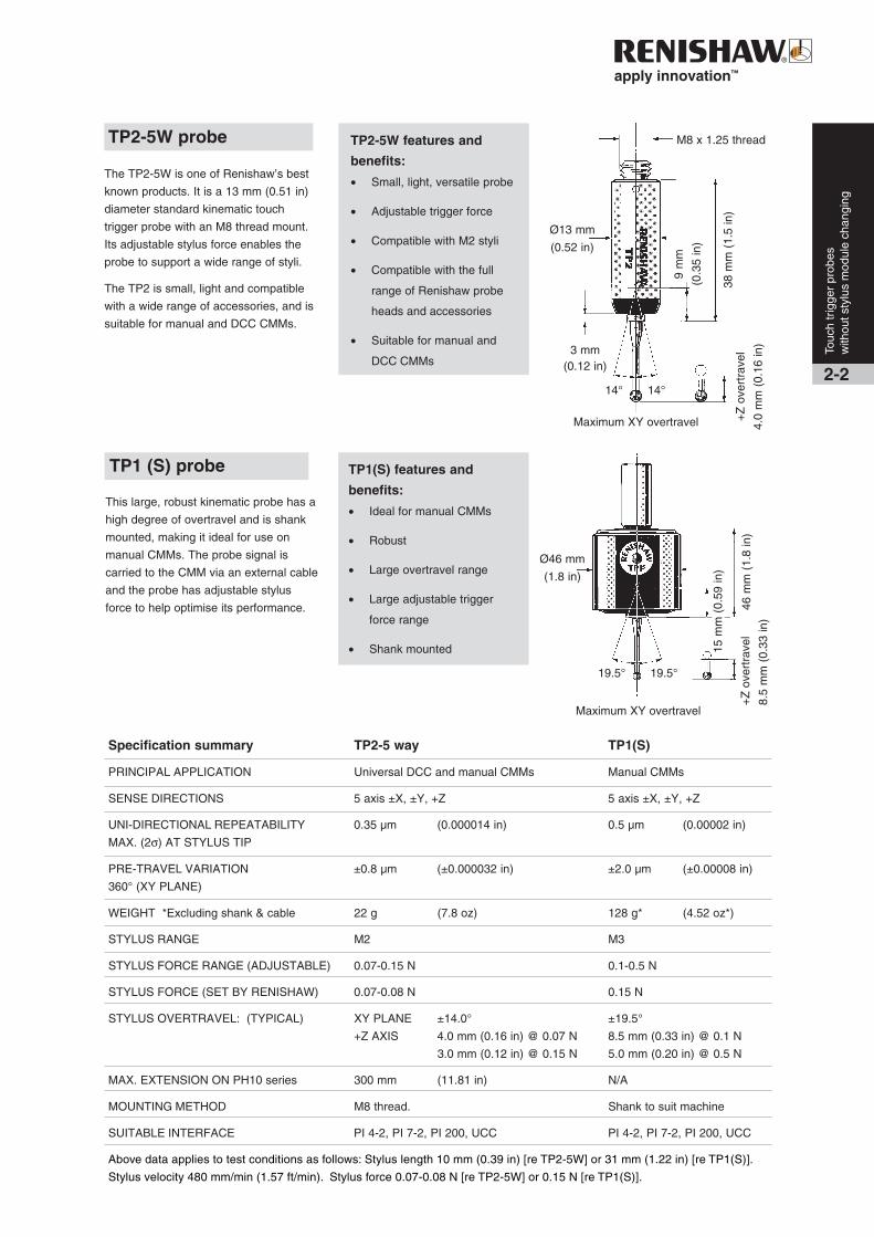
Specification summary TP2-5 way TP1(S)
PRINCIPAL APPLICATION Universal DCC and manual CMMs Manual CMMs
SENSE DIRECTIONS 5 axis ±X, ±Y, +Z 5 axis ±X, ±Y, +Z
UNI-DIRECTIONAL REPEATABILITY 0.35 µm (0.000014 in) 0.5 µm (0.00002 in)
MAX. (2σ) AT STYLUS TIP
PRE-TRAVEL VARIATION ±0.8 µm (±0.000032 in) ±2.0 µm (±0.00008 in)
360° (XY PLANE)
WEIGHT *Excluding shank & cable 22 g (7.8 oz) 128 g* (4.52 oz*)
STYLUS RANGE M2 M3
STYLUS FORCE RANGE (ADJUSTABLE) 0.07-0.15 N 0.1-0.5 N
STYLUS FORCE (SET BY RENISHAW) 0.07-0.08 N 0.15 N
STYLUS OVERTRAVEL: (TYPICAL) XY PLANE ±14.0° ±19.5°
+Z AXIS 4.0 mm (0.16 in) @ 0.07 N 8.5 mm (0.33 in) @ 0.1 N
3.0 mm (0.12 in) @ 0.15 N 5.0 mm (0.20 in) @ 0.5 N
MAX. EXTENSION ON PH10 series 300 mm (11.81 in) N/A
MOUNTING METHOD M8 thread. Shank to suit machine
SUITABLE INTERFACE PI 4-2, PI 7-2, PI 200, UCC PI 4-2, PI 7-2, PI 200, UCC
Above data applies to test conditions as follows: Stylus length 10 mm (0.39 in) [re TP2-5W] or 31 mm (1.22 in) [re TP1(S)].
Stylus velocity 480 mm/min (1.57 ft/min). Stylus force 0.07-0.08 N [re TP2-5W] or 0.15 N [re TP1(S)].
TP2-5W features and
benefits:
• Small, light, versatile probe
• Adjustable trigger force
• Compatible with M2 styli
• Compatible with the full
range of Renishaw probe
heads and accessories
• Suitable for manual and
DCC CMMs
The TP2-5W is one of Renishaw’s best
known products. It is a 13 mm (0.51 in)
diameter standard kinematic touch
trigger probe with an M8 thread mount.
Its adjustable stylus force enables the
probe to support a wide range of styli.
The TP2 is small, light and compatible
with a wide range of accessories, and is
suitable for manual and DCC CMMs.
TP2-5W probe
Touc
h tr
igge
r pr
obes
with
out s
tylu
s m
odul
e ch
angi
ng
TP1(S) features and
benefits:
• Ideal for manual CMMs
• Robust
• Large overtravel range
• Large adjustable trigger
force range
• Shank mounted
Ø13 mm
(0.52 in)
+Z
ove
rtra
vel
4.0
mm
(0.
16 in
)
38 m
m (
1.5
in)
3 mm(0.12 in)
14° 14°
Maximum XY overtravel
9 m
m
(0.3
5 in
)
This large, robust kinematic probe has a
high degree of overtravel and is shank
mounted, making it ideal for use on
manual CMMs. The probe signal is
carried to the CMM via an external cable
and the probe has adjustable stylus
force to help optimise its performance.
TP1 (S) probe
Ø46 mm
(1.8 in)
+Z
ove
rtra
vel
8.5
mm
(0.
33 in
)46
mm
(1.
8 in
)
Maximum XY overtravel
19.5° 19.5°
15 m
m (
0.59
in)
M8 x 1.25 thread

Probing systems forco-ordinate measuring machines
Specification summary TP6 TP6A
PRINCIPAL APPLICATION Robust universal DCC and manual As TP6 but with fast probe exchange
CMMs without requalification
SENSE DIRECTIONS 5 axis ±X, ±Y, +Z 5 axis ±X, ±Y, +Z
UNI-DIRECTIONAL REPEATABILITY 0.35 µm (0.000014 in) 0.35 µm (0.000014 in)
MAX. (2σ) AT STYLUS TIP
PRE-TRAVEL VARIATION ±1.0 µm (±0.00004 in) ±1.0 µm (±0.00004 in)
360° (XY PLANE)
WEIGHT 56 g (1.98 oz) 76 g (2.68 oz)
STYLUS RANGE M3 M3
STYLUS FORCE RANGE (ADJUSTABLE) 0.11-0.3 N 0.11-0.3 N
STYLUS FORCE (SET BY RENISHAW) 0.11-0.13 N 0.11-0.13 N
STYLUS OVERTRAVEL : XY PLANE ±22.0° ±22.0°
(TYPICAL) +Z AXIS 5.5 mm (0.22 in) @ 0.11 N 5.5 mm (0.22 in) @ 0.11 N
2.0 mm (0.08 in) @ 0.3 N 2.0 mm (0.08 in) @ 0.3 N
MAX. EXTENSION ON PH10 series 200 mm (7.87 in) 200 mm (7.87 in)
MOUNTING METHOD M8 thread connector Autojoint
SUITABLE INTERFACE PI 4-2, PI 7-2, PI 200, UCC PI 4-2, PI 7-2, PI 200, UCC
Above data applies to test conditions as follows: Stylus length 21 mm (0.83 in).Stylus velocity 480 mm/min (1.57 ft/min). Stylus force 0.11-0.13 N
TP6 probes have better accuracy
and can carry longer styli than the
smaller TP2/TP20 probes. The TP6
is an M8 thread mounted probe
while the TP6A has an autojoint,
which means that it can be
changed quickly and easily without
the need to re-qualify stylus tips.
The probe design is robust with
large overtravel and adjustable
trigger force.M3 x 0.5thread
Ø25 mm(0.98 in)
Maximum XY overtravel
41 m
m (
1.61
in)
6.5 mm(0.25 in)
15 m
m(0
.59
in)
+Z overtravel5.5 mm (0.22 in)22° 22°2-3
Touc
h tr
igge
r pr
obes
with
out s
tylu
s m
odul
e ch
angi
ng
TP6 / TP6A probe TP6M8 x 1.25 thread
TP6 / TP6A features and
benefits:
• Autojoint or M8 version
• Long stylus carrying
capability
• Large stylus overtravel
• Robust
• Adjustable trigger force
range
• M3 stylus mount
46.5
mm
(1.
83 in
)
+Z overtravel
5.5 mm (0.22 in)
49 m
m (
1.93
in)
22° 22°
Ø25 mm(0.98 in)
Maximum XY overtravel
6.5 mm(0.25 in) 15
mm
(0.5
9 in
)
TP6 A
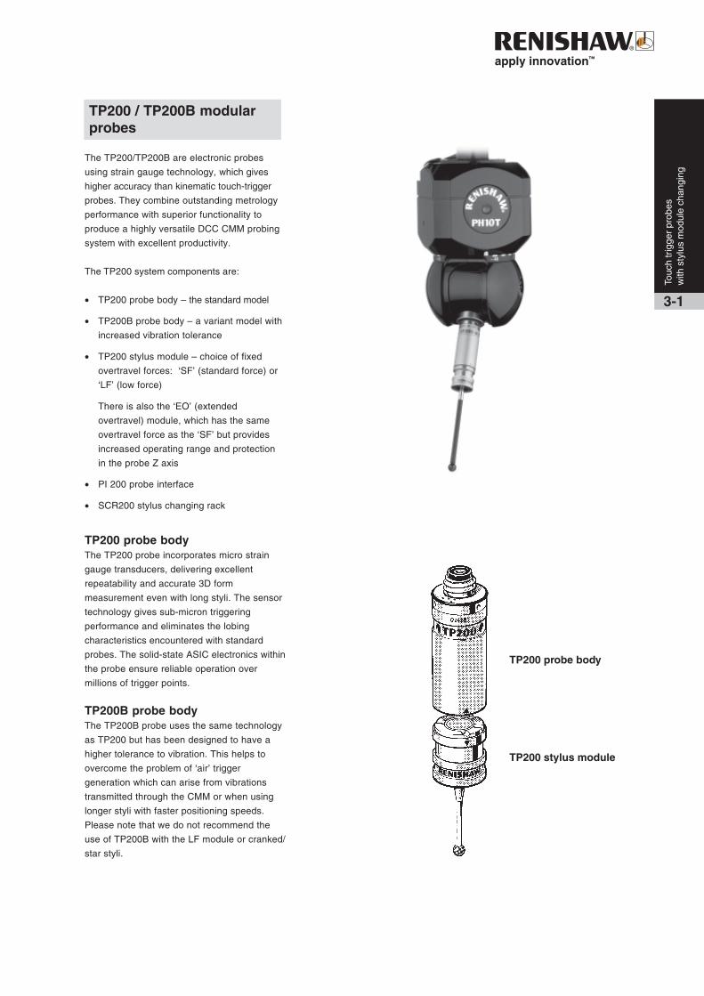
TP200 / TP200B modularprobes
The TP200/TP200B are electronic probes
using strain gauge technology, which gives
higher accuracy than kinematic touch-trigger
probes. They combine outstanding metrology
performance with superior functionality to
produce a highly versatile DCC CMM probing
system with excellent productivity.
The TP200 system components are:
• TP200 probe body – the standard model
• TP200B probe body – a variant model with
increased vibration tolerance
• TP200 stylus module – choice of fixed
overtravel forces: ‘SF’ (standard force) or
‘LF’ (low force)
There is also the ‘EO’ (extended
overtravel) module, which has the same
overtravel force as the ‘SF’ but provides
increased operating range and protection
in the probe Z axis
• PI 200 probe interface
• SCR200 stylus changing rack
TP200 probe bodyThe TP200 probe incorporates micro strain
gauge transducers, delivering excellent
repeatability and accurate 3D form
measurement even with long styli. The sensor
technology gives sub-micron triggering
performance and eliminates the lobing
characteristics encountered with standard
probes. The solid-state ASIC electronics within
the probe ensure reliable operation over
millions of trigger points.
TP200B probe bodyThe TP200B probe uses the same technology
as TP200 but has been designed to have a
higher tolerance to vibration. This helps to
overcome the problem of ‘air’ trigger
generation which can arise from vibrations
transmitted through the CMM or when using
longer styli with faster positioning speeds.
Please note that we do not recommend the
use of TP200B with the LF module or cranked/
star styli.
2-1Touc
h tr
igge
r pr
obes
with
sty
lus
mod
ule
chan
ging
3-1
TP200 probe body
TP200 stylus module
Probing systems forco-ordinate measuring machines
3-2
Touc
h tr
igge
r pr
obes
with
sty
lus
mod
ule
chan
ging
245 mm(9.65 in)
190
mm
(7.8
4 in
)
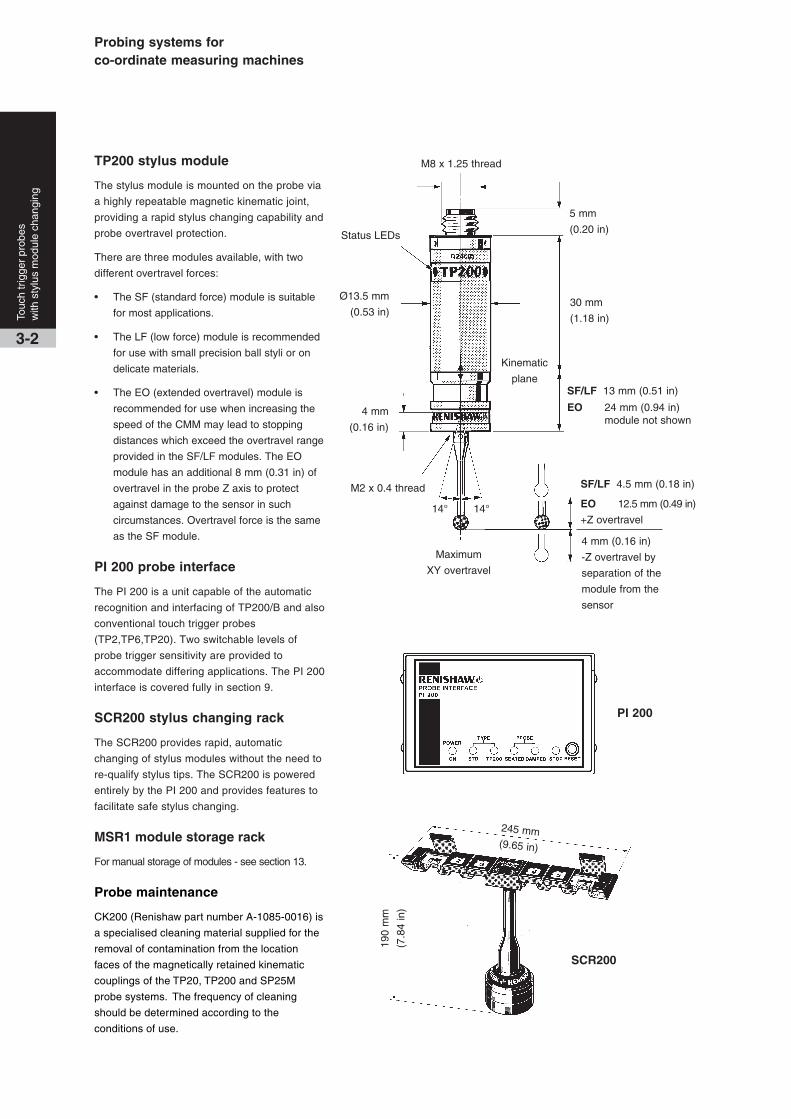
TP200 stylus module
The stylus module is mounted on the probe via
a highly repeatable magnetic kinematic joint,
providing a rapid stylus changing capability and
probe overtravel protection.
There are three modules available, with two
different overtravel forces:
• The SF (standard force) module is suitable
for most applications.
• The LF (low force) module is recommended
for use with small precision ball styli or on
delicate materials.
• The EO (extended overtravel) module is
recommended for use when increasing the
speed of the CMM may lead to stopping
distances which exceed the overtravel range
provided in the SF/LF modules. The EO
module has an additional 8 mm (0.31 in) of
overtravel in the probe Z axis to protect
against damage to the sensor in such
circumstances. Overtravel force is the same
as the SF module.
PI 200 probe interface
The PI 200 is a unit capable of the automatic
recognition and interfacing of TP200/B and also
conventional touch trigger probes
(TP2,TP6,TP20). Two switchable levels of
probe trigger sensitivity are provided to
accommodate differing applications. The PI 200
interface is covered fully in section 9.
SCR200 stylus changing rack
The SCR200 provides rapid, automatic
changing of stylus modules without the need to
re-qualify stylus tips. The SCR200 is powered
entirely by the PI 200 and provides features to
facilitate safe stylus changing.
MSR1 module storage rack
For manual storage of modules - see section 13.
Probe maintenance
CK200 (Renishaw part number A-1085-0016) is
a specialised cleaning material supplied for the
removal of contamination from the location
faces of the magnetically retained kinematic
couplings of the TP20, TP200 and SP25M
probe systems. The frequency of cleaning
should be determined according to the
conditions of use.
SCR200
PI 200
M2 x 0.4 thread
Ø13.5 mm
(0.53 in)
4 mm
(0.16 in)
Maximum
XY overtravel
14° 14°
SF/LF 13 mm (0.51 in)
EO 24 mm (0.94 in)module not shown
SF/LF 4.5 mm (0.18 in)
EO 12.5 mm (0.49 in)
+Z overtravel
4 mm (0.16 in)
-Z overtravel by
separation of the
module from the
sensor
5 mm
(0.20 in)Status LEDs
M8 x 1.25 thread
30 mm
(1.18 in)
Kinematic
plane
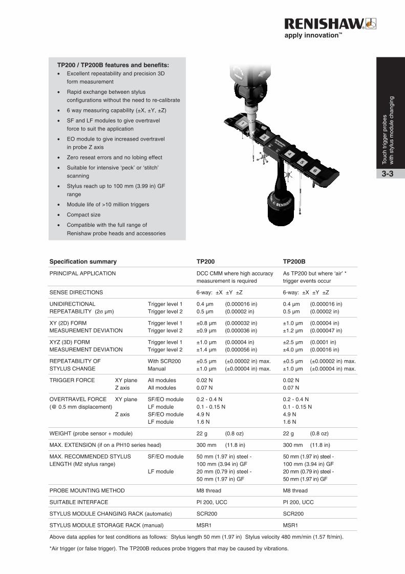
Specification summary TP200 TP200B
PRINCIPAL APPLICATION DCC CMM where high accuracy As TP200 but where ‘air’ *measurement is required trigger events occur
SENSE DIRECTIONS 6-way: ±X ±Y ±Z 6-way: ±X ±Y ±Z
UNIDIRECTIONAL Trigger level 1 0.4 µm (0.000016 in) 0.4 µm (0.000016 in)REPEATABILITY (2σ µm) Trigger level 2 0.5 µm (0.00002 in) 0.5 µm (0.00002 in)
XY (2D) FORM Trigger level 1 ±0.8 µm (0.000032 in) ±1.0 µm (0.00004 in)MEASUREMENT DEVIATION Trigger level 2 ±0.9 µm (0.000036 in) ±1.2 µm (0.000047 in)
XYZ (3D) FORM Trigger level 1 ±1.0 µm (0.00004 in) ±2.5 µm (0.0001 in)MEASUREMENT DEVIATION Trigger level 2 ±1.4 µm (0.000056 in) ±4.0 µm (0.00016 in)
REPEATABILITY OF With SCR200 ±0.5 µm (±0.00002 in) max. ±0.5 µm (±0.00002 in) max.STYLUS CHANGE Manual ±1.0 µm (±0.00004 in) max. ±1.0 µm (±0.00004 in) max.
TRIGGER FORCE XY plane All modules 0.02 N 0.02 NZ axis All modules 0.07 N 0.07 N
OVERTRAVEL FORCE XY plane SF/EO module 0.2 - 0.4 N 0.2 - 0.4 N(@ 0.5 mm displacement) LF module 0.1 - 0.15 N 0.1 - 0.15 N
Z axis SF/EO module 4.9 N 4.9 NLF module 1.6 N 1.6 N
WEIGHT (probe sensor + module) 22 g (0.8 oz) 22 g (0.8 oz)
MAX. EXTENSION (if on a PH10 series head) 300 mm (11.8 in) 300 mm (11.8 in)
MAX. RECOMMENDED STYLUS SF/EO module 50 mm (1.97 in) steel - 50 mm (1.97 in) steel -LENGTH (M2 stylus range) 100 mm (3.94 in) GF 100 mm (3.94 in) GF
LF module 20 mm (0.79 in) steel - 20 mm (0.79 in) steel -50 mm (1.97 in) GF 50 mm (1.97 in) GF
PROBE MOUNTING METHOD M8 thread M8 thread
SUITABLE INTERFACE PI 200, UCC PI 200, UCC
STYLUS MODULE CHANGING RACK (automatic) SCR200 SCR200
STYLUS MODULE STORAGE RACK (manual) MSR1 MSR1
Above data applies for test conditions as follows: Stylus length 50 mm (1.97 in) Stylus velocity 480 mm/min (1.57 ft/min).
*Air trigger (or false trigger). The TP200B reduces probe triggers that may be caused by vibrations.
3-3
TP200 / TP200B features and benefits:• Excellent repeatability and precision 3D
form measurement
• Rapid exchange between stylus
configurations without the need to re-calibrate
• 6 way measuring capability (±X, ±Y, ±Z)
• SF and LF modules to give overtravel
force to suit the application
• EO module to give increased overtravel
in probe Z axis
• Zero reseat errors and no lobing effect
• Suitable for intensive ‘peck’ or ‘stitch’
scanning
• Stylus reach up to 100 mm (3.99 in) GF
range
• Module life of >10 million triggers
• Compact size
• Compatible with the full range of
Renishaw probe heads and accessories
Touc
h tr
igge
r pr
obes
with
sty
lus
mod
ule
chan
ging

Probing systems forco-ordinate measuring machines
3-4
Touc
h tr
igge
r pr
obes
with
sty
lus
mod
ule
chan
ging
TP20 probe body
TP20 / TP20 NI modular probes
The TP20 is a 5-way or 6-way kinematic touch trigger
probe. Its two piece design comprises a probe body and
detachable stylus module(s), which gives the ability to
change stylus configurations either manually or
automatically without re-qualification of the stylus tips,
providing significant time savings in inspection routines.
A direct replacement for the industry standard
Renishaw TP2 probe, the TP20 probe system brings a
range of new benefits to manual and DCC CMM
applications, and can easily be retrofitted to existing
TP2 installations.
The TP20 can be used on a wide range of Renishaw’s
manual or motorised probe heads, either by direct
mounting using the standard M8 thread or, alternatively,
by using a PAA# adaptor to connect to an autojoint.
The system components are:
• TP20/TP20 NI probe body
• TP20 stylus module – seven module variants allow
for optimisation of performance to suit the
application
• MCR20 module changing rack – automatic
operation
• The TP20 probe system may be used with
Renishaw’s PI 4-2, PI 7-2 or PI 200 probe
interfaces (see section 9)
TP20 probe body
The TP20 probe body houses one half of the highly
repeatable magnetic kinematic coupling that attaches
the stylus module and body. The body also contains a
magnetic proximity switch to inhibit triggering of the
probe during automatic module changing with MCR20.
Note: If the probe is operated close to magnetised
parts/clamping etc, the probe trigger may become
inhibited. Countermeasures include the use of long
styli, stylus extensions or body orientation to increase
the distance to the magnetic source. Alternatively, use
the TP20 NI probe body.
TP20 NI probe body
The TP20 NI probe differs from the TP20 body in that it
is not affected by magnetic fields. However the probe
trigger must be inhibited through software during
change cycles using the MCR20.
SF
/LF
/MF
/EF
38
mm
(1.
50 in
)
6
W 4
2 m
m (
1.65
)
E
M1
88 m
m (
3.46
)
E
M2
113
mm
(4.
45)
14°14°
3 mm
(0.12 in)
9.0
mm
(0.
35 in
)Ø13.2 mm
(0.52 in)
M8 x 1.25 thread
+Z overtravel
-Z overtravel
+Z overtravelSF/EM1/EM2 4.0 mm (0.16 in)
LF 3.1 mm (0.12 in)
MF 3.7 mm (0.15 in)
EF 2.4 mm (0.09 in)
6W 4.5 mm (0.177 in)
-Z overtravel6W 1.5 mm (0.06 in)
TP20 stylus modules(7 variants)

3-5
Touc
h tr
igge
r pr
obes
with
sty
lus
mod
ule
chan
ging
TP20 stylus module
The TP20 stylus module houses the kinematic
switching touch sensor mechanism, carries the
stylus assembly and provides overtravel in ±X,
±Y and +Z axes (or ±Z in the case of TP20
6-way module). The stylus mounting thread
accepts styli from the Renishaw M2 range.
A range of seven, application specific, stylus
modules is available, being identified by
coloured caps:
• SF - Standard force stylus module
(black cap)
• LF - Low force stylus module
(green cap)
• MF - Medium force stylus module
(grey cap)
• EF - Extended force stylus module
(brown cap)
• 6W - 6-way stylus module
(blue cap)
• EM1 SF - Standard force extension
module
• EM2 SF - Standard force extension
module
MCR20 module changing rack
The MCR20 probe module changing rack is
designed to securely store stylus modules
ready for rapid automatic changing, whilst
protecting mating surfaces from any airborne
contaminants within the working environment.
MSR1 module storage rack
For manual storage of modules - see section 13.
Probe maintenance
CK200 (Renishaw part number A-1085-0016)
is a specialised cleaning material supplied for
the removal of contamination from the
location faces of the magnetically retained
kinematic couplings of the TP20, TP200 and
SP25M probe systems. The frequency of
cleaning should be determined according to
the conditions of use.
LF SF MF EF 6W EM1 EM2
EM2
extension
module
10 mm(0.39 in)
50 mm (1.96 in)
100 mm (3.93 in)
125 mm (4.92 in)
EM1
extension
module
MCR20
200 mm (7.87 in)
145
mm
(5.
70 in
)
Ø55 mm (2.16 in)
15 mm
(0.59 in)
60 mm
(2.36 in)
Stylus module comparison
60 mm (2.36 in)
30 mm(1.18 in)
Probing systems forco-ordinate measuring machines
3-6
Touc
h tr
igge
r pr
obes
with
sty
lus
mod
ule
chan
ging
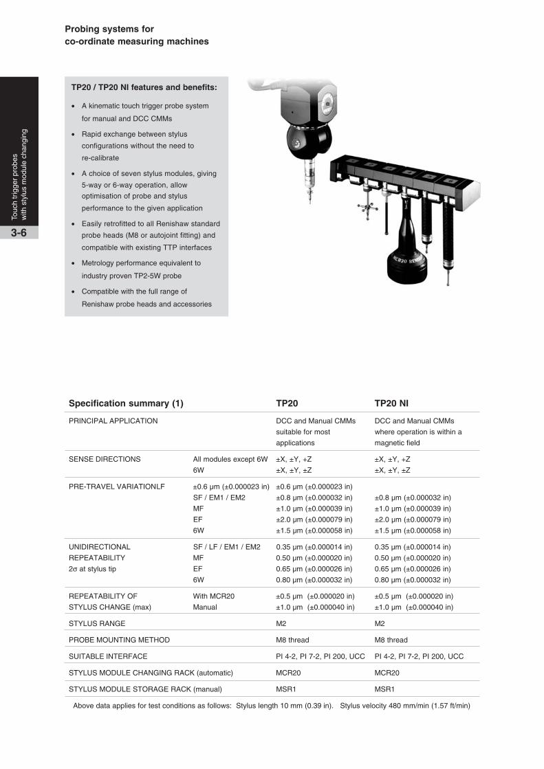
TP20 / TP20 NI features and benefits:
• A kinematic touch trigger probe system
for manual and DCC CMMs
• Rapid exchange between stylus
configurations without the need to
re-calibrate
• A choice of seven stylus modules, giving
5-way or 6-way operation, allow
optimisation of probe and stylus
performance to the given application
• Easily retrofitted to all Renishaw standard
probe heads (M8 or autojoint fitting) and
compatible with existing TTP interfaces
• Metrology performance equivalent to
industry proven TP2-5W probe
• Compatible with the full range of
Renishaw probe heads and accessories
Specification summary (1) TP20 TP20 NI
PRINCIPAL APPLICATION DCC and Manual CMMs DCC and Manual CMMs
suitable for most where operation is within a
applications magnetic field
SENSE DIRECTIONS All modules except 6W ±X, ±Y, +Z ±X, ±Y, +Z
6W ±X, ±Y, ±Z ±X, ±Y, ±Z
PRE-TRAVEL VARIATIONLF ±0.6 µm (±0.000023 in) ±0.6 µm (±0.000023 in)
SF / EM1 / EM2 ±0.8 µm (±0.000032 in) ±0.8 µm (±0.000032 in)
MF ±1.0 µm (±0.000039 in) ±1.0 µm (±0.000039 in)
EF ±2.0 µm (±0.000079 in) ±2.0 µm (±0.000079 in)
6W ±1.5 µm (±0.000058 in) ±1.5 µm (±0.000058 in)
UNIDIRECTIONAL SF / LF / EM1 / EM2 0.35 µm (±0.000014 in) 0.35 µm (±0.000014 in)
REPEATABILITY MF 0.50 µm (±0.000020 in) 0.50 µm (±0.000020 in)
2σ at stylus tip EF 0.65 µm (±0.000026 in) 0.65 µm (±0.000026 in)
6W 0.80 µm (±0.000032 in) 0.80 µm (±0.000032 in)
REPEATABILITY OF With MCR20 ±0.5 µm (±0.000020 in) ±0.5 µm (±0.000020 in)
STYLUS CHANGE (max) Manual ±1.0 µm (±0.000040 in) ±1.0 µm (±0.000040 in)
STYLUS RANGE M2 M2
PROBE MOUNTING METHOD M8 thread M8 thread
SUITABLE INTERFACE PI 4-2, PI 7-2, PI 200, UCC PI 4-2, PI 7-2, PI 200, UCC
STYLUS MODULE CHANGING RACK (automatic) MCR20 MCR20
STYLUS MODULE STORAGE RACK (manual) MSR1 MSR1
Above data applies for test conditions as follows: Stylus length 10 mm (0.39 in). Stylus velocity 480 mm/min (1.57 ft/min)

Specification summary (2)
Module Application guide Max extension on WeightPH10 series head (Body and module)
SF The standard force stylus modules, identified by black caps, 300 mm (11.81 in) 22 g (0.77 oz)EM1 are suited to the majority of applications. 300 mm (11.81 in) * 28 g (0.98 oz)EM2 300 mm (11.81 in) * 30 g (1.05 oz)
LF The low force stylus module, identified by a green cap,is suited to applications that require low trigger force, 300 mm (11.81 in) 22 g (0.77 oz)e.g. rubber seals.
MF The medium force stylus module, identified by a grey cap,is for use where a higher trigger force than standard is 300 mm (11.81 in) 22 g (0.77 oz)required.
EF The extended force stylus module is identified by a browncap. Typically, this stylus module will only be required withlarge stylus assemblies, and where spurious ‘air’ triggers 300 mm (11.81 in) 22 g (0.77 oz)caused by machine vibration and acceleration, preclude theuse of either SF, LF or MF modules.
6W The 6-way stylus module, identified by a blue cap, has beendesigned for applications requiring measurement in the –Z 300 mm (11.81 in) 25 g (0.88 oz)direction, for example when measuring the width of undercuts.
Specification summary (3)
SF10 mm
LF10 mm
MF25 mm
EF50 mm
6W10 mm
EM110 mm
EM210 mm
XY
0.08 N
0.055 N
0.1 N
0.1 N
0.14 N
0.08 N
0.08 N
Z
0.75 N
0.65 N
1.9 N
3.2 N
1.6 N
0.75 N
0.75 N
XY
0.2-0.3 N
0.09 N
0.2-0.4 N
0.2-0.5 N
0.25 N
0.2-0.3 N
0.2-0.3 N
+Z
3.5 N
1.15 N
7.0 N
10.0 N
2.5 N
3.5 N
3.5 N
-Z
-
-
-
-
9.0 N
-
-
XY
±14°
±14°
±14°
±14°
±14°
±14°
±14°
+Z
4.0 mm
(0.16 in)
3.1 mm
(0.12 in)
3.7 mm
(0.15)
2.4 mm
(0.09 in)
4.5 mm
(0.18 in)
4.0 mm
(0.16 in)
4.0 mm
(0.16 in)
-Z
-
-
-
-
1.5 mm
(0.059 in)
-
-
Overtraveldisplacement
Overtravel forceTrigger force
Above data applies for test conditions as follows: Stylus length as stated above. Stylus velocity 480 mm/min (1.57 ft/min)
3-7
Touc
h tr
igge
r pr
obes
with
sty
lus
mod
ule
chan
ging
Moduletype andtest styluslength
* Note: Dependant on CMM used and operating conditions

Probing systems forco-ordinate measuring machines
SP25M scanning probeOnly 25 mm (0.98 in) in diameter, and with a range of
modules for high performance scanning and touch-
trigger probing, the SP25M is the world’s most
compact and versatile scanning probe system.
The SP25M is actually two sensors in one, enabling
scanning and touch-trigger probing in a single probe
system. SP25M gives highly accurate scanning
performance with stylus lengths from 20 mm to
400 mm (0.78 in to 15.75 in) using M3 stylus range. In
addition, the ability to carry Renishaw’s TP20 range of
touch-trigger stylus modules means that the SP25M
system enables best optimisation of the measurement
solution to suit the application.
The SP25M’s compact size and autojoint mounting
make it compatible with the PH10M/MQ motorised
probe heads and PH6M fixed probe head. It can also
be mounted on a multiwired extension bar of up to 100
mm length. Together, this combination permits
excellent reach and access to part features.
A unique pivoting design achieves exceptional
dynamic performance. Four scanning modules have
been designed to optimise scanning accuracy across a
wide range of stylus lengths, avoiding most of the
deterioration in performance seen in other types of
scanning probe as stylus lengths increase.
• The world’s most compact and versatile scanning
probe system
• Two sensors in one - a scanning probe, and a touch
trigger probe using TP20 stylus modules
• Rapid and repeatable interchange between highly
modular system elements provides the most efficient
solution to suit the measurement task
• Excellent scanning accuracy across the entire stylus
range of 20 - 400 mm (0.78 - 15.75 in)
• Can be used with extension bars up to 100 mm for
even greater reach
• Probe can be mounted on an articulating head,
allowing access to many features with fewer styli
4-1
Sca
nnin
g pr
obes
SP25M compact scanningprobe system
SM25-4 module can scan verydeep features - shown here with
400 mm (15.75 in) stylus
SP25M features and benefits
• Ultra-compact at Ø25 mm (Ø0.98 in) for superior
part accessibility
• Isolated optical metrology technology gives
unrivalled measurement performance, even with
long styli
• Flexible change rack where ports can be easily
configured to carry any system element
••••• Bump-stop crash protection in the Z axis, together
with a detachable stylus holder for XY crash
protection
• Low-cost, entry level kits available with ability to
easily expand the system

SP25M probe body
TP20module SH25-1
SH25-2
SH25-3
EWL20 - 50 mm
(0.79 - 1.97 in)
EWL50 - 105 mm
(1.97 - 4.13 in)
EWL120 - 200 mm(4.72 - 7.87 in)
EWL - Effectiveworking length
Sca
nnin
g pr
obes
4-2
TM25-20 SM25-1 SM25-2 SM25-3 SM25-4
SH25-4
EWL220 - 400 mm
(8.66 - 15.75 in)
SP25M modular component system

Probing systems forco-ordinate measuring machines
The SP25M system components
The SP25M probe body, which houses the isolated optical metrology
transducer system, has autojoint compatibility with Renishaw’s PH10M/MQ,
and PH6M probe heads, extension bars and ACR1/3 sensor changers.
A range of four scanning modules SM25-1/-2/-3/-4 has been designed to
provide optimised scanning performance over their specified stylus length
ranges. The SP25M’s innovative pivot-action motion, and the isolated optical
metrology approach, mean that excellent accuracy is achieved over the
entire stylus length range of 20 mm to 400 mm (0.78 in to 15.75 in).
SH25-1/-2/-3/-4 stylus holders provide the flexibility to have multiple stylus
set-ups for each scanning module. The detachable stylus holder is located
on the scanning module using a repeatable magnetic kinematic joint. It
provides automatic stylus changing capability and directly carries Renishaw’s
M3 stylus range.
It is also possible to carry Renishaw’s TP20 range of touch trigger probe
modules by using the TM25-20 adaptor module mounted on the SP25M
probe body.
Rapid and repeatable interchange between all system elements allows easy
selection of best probe solution. This can be automated to maximise
productivity by using the FCR25 flexible change rack.
The SP25M can be connected directly to the UCC2 controller while a
daughtercard permits use with Renishaw’s UCC1 controller. The AC3
interface card allows integration with other controllers.
Using SP25M as a scanning probe:The probe body has one of the three scanning modules attached
(SM25-1/-2/-3/-4) which have matching stylus holders (SH25-1/-2/-3/-4).
Each combination is optimised to maintain high accuracy and low contact
forces over their dedicated range of effective stylus lengths. These are:
• SM25-1 + SH25-1 = 20 mm - 50 mm (0.78 in -1.97 in) EWL
by use of 20 mm - 50 mm (0.78 in - 1.97 in) stylus
• SM25-2 + SH25-2 = 50 mm - 105 mm (1.97 in - 4.13 in) EWL
by use of 20 mm - 75 mm (0.78 in - 2.95 in) stylus
• SM25-3 + SH25-3 = 120 mm - 200 mm (4.72 in - 7.87 in) EWL
by use of 20 mm - 100 mm (0.78 in - 3.94 in) stylus
• SM25-4 + SH25-4 = 220 mm - 400 mm (8.66 in - 15.75 in) EWL
by use of 20 mm - 200 mm (0.78 in - 7.87 in) stylus
Using SP25M as a touch-trigger probe:
The probe body has the TM25-20 adaptor module attached, which directly
carries any of Renishaw’s TP20 range of stylus modules:
• TP20 LF/SF/MF/EF
• TP20 EM1/EM2
• TP20-6W
Interfacing options
SP25M can be integrated:
• directly using the UCC2 controller (requires scanning upgrade)
• by using Renishaw’s UCC1 controller (requires scanning
upgrade) together with a SP25M/UCC1 daughtercard
• by using Renishaw’s AC3 interface card (ISA Bus) within the
machine builder’s controller
SP25M scanning
SP25M takingpoints with aTP20 module
SP25M with 100 mm(3.94 in) extension bar
between PH10 headand probe body
4-3
Sca
nnin
g pr
obes

4-4
Sca
nnin
g pr
obes
Automation using the FCR25 flexible change rack
The full potential of the SP25M system is realised when the
measurement routine is automated using the FCR25 flexible change
rack, a passive triple-port unit capable of storing any of the system
elements.
The FCR25 port stores the SM25-1/-2/-3/-4 and TM25-20 modules,
but can instantly be configured to store the SH25-1/-2/-3/-4 stylus
holders or TP20 modules by using the appropriate port adaptor
insert: PA25-SH (for SH25-1/-2/-3/-4) or PA25-20 (for TP20
modules).
The FCR25 mounts directly on Renishaw’s MRS modular rack
system for multiple port solutions (3, 6, 9, 12, 15 etc). Alternatively,
there is FCR25-L3 (3 port) and FCR25-L6 (6 port) stand-alone rack
variants which are ideal where machine space is limited.
Probe maintenance
CK200 (Renishaw part number A-1085-0016) is a specialised
cleaning material, for the removal of contamination from the location
faces of the magnetically retained kinematic couplings of the TP20,
TP200 and SP25M probe systems. The frequency of cleaning should
be determined according to the conditions of use.
FCR25-L3 (3 port)FCR25-L6 (6 port)
FCR25
219.5 mm (8.64 in)
166
mm
(6.
54 in
)
113.8 mm (4.45 in)
166
mm
(6.
54 in
)
FCR25’s mounted to the MRS
21.6
mm
(0
.85
in)
39.5
mm
(1.55
in)
28 m
m(1
.10
in)
113.8 (4.45 in)
35 mm (1.38 in)nominal pitch
74.5
mm (2.93
in)
PA25-20
PA25-5H
Probing systems forco-ordinate measuring machines
Sca
nnin
g pr
obes
4-5
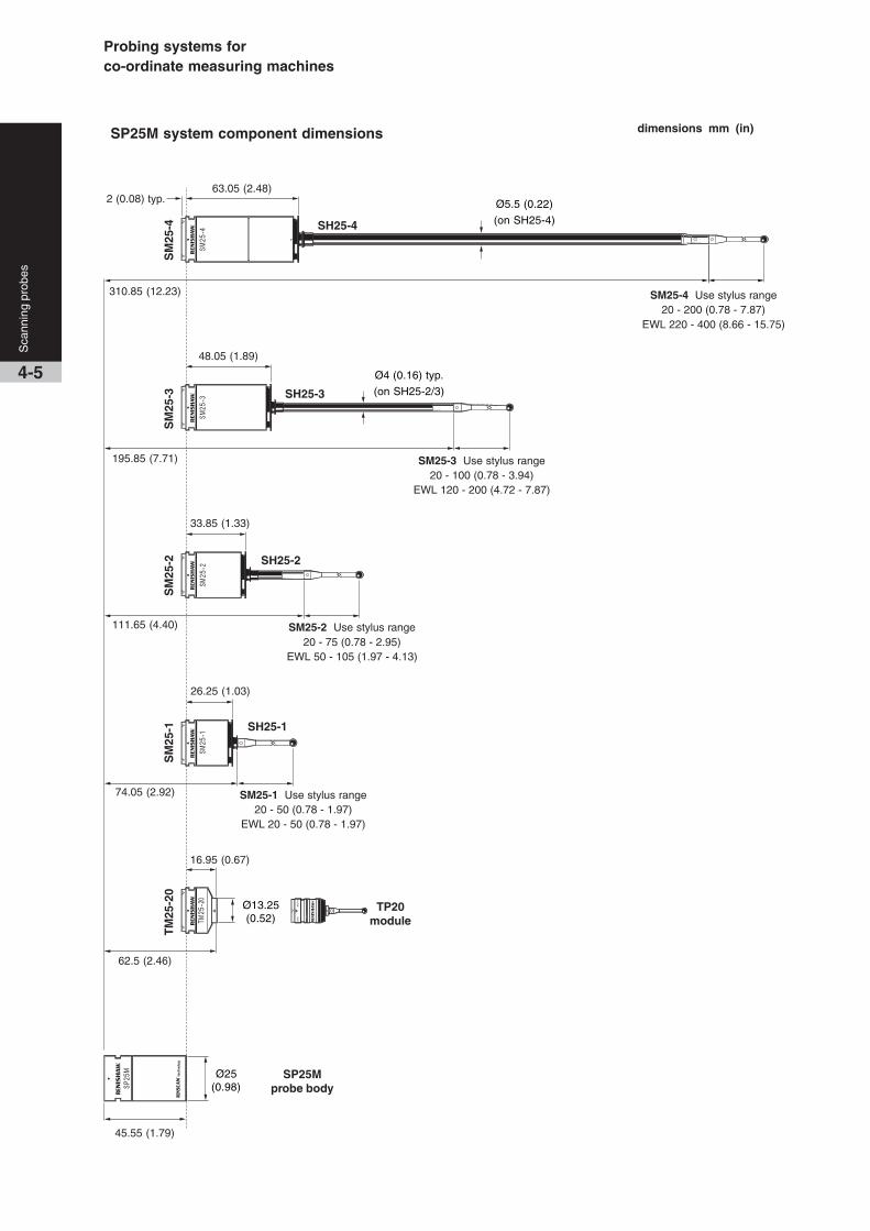
dimensions mm (in)SP25M system component dimensions
SP25Mprobe body
TP20module
45.55 (1.79)
SH25-3
SH25-2
SH25-1
74.05 (2.92)
16.95 (0.67)
62.5 (2.46)
SM25-1 Use stylus range20 - 50 (0.78 - 1.97)
EWL 20 - 50 (0.78 - 1.97)
SM25-2 Use stylus range20 - 75 (0.78 - 2.95)
EWL 50 - 105 (1.97 - 4.13)
SM25-3 Use stylus range20 - 100 (0.78 - 3.94)
EWL 120 - 200 (4.72 - 7.87)
195.85 (7.71)
26.25 (1.03)
33.85 (1.33)
48.05 (1.89)
Ø25(0.98)
Ø4 (0.16) typ.
(on SH25-2/3)
2 (0.08) typ.
111.65 (4.40)
Ø13.25(0.52)
SM25-4 Use stylus range20 - 200 (0.78 - 7.87)
EWL 220 - 400 (8.66 - 15.75)
SH25-4
63.05 (2.48)
310.85 (12.23)
Ø5.5 (0.22)
(on SH25-4)
SM
25-1
SM
25-2
SM
25-3
TM
25-2
0S
M25
-4

Sca
nnin
g pr
obes
4-6
Specification summary SP25M
PROBE ATTRIBUTES Scanning with 3 axis measurement (X,Y,Z)
Touch trigger probing using TP20 modules *
MEASUREMENT RANGE ±0.5 mm (0.02 in) deflection in all directions in all orientations
OVERTRAVEL RANGE (nom) X,Y = ±2.0 mm (±0.08 in) min, +Z = 1.7 mm (0.07 in), -Z = 1.2 mm (0.05 in)
RESOLUTION Capable of <0.1 µm (<0.00004 in)
SPRING RATE Nominally 0.6 N/mm - when using module’s shortest specified stylus
Nominally 0.2 N/mm - when using module’s longest specified stylus
PROBE DIMENSIONS Ø25 mm x length dependant on module used (see schematic above)
WEIGHT: SP25M body 65 g (2.29 oz)
SM25-1 scan module 35 g (1.23 oz) including SH25-1, but excluding stylus
SM25-2 scan module 40 g (1.41 oz) including SH25-2 but excluding stylus
SM25-3 scan module 49 g (1.73 oz) including SH25-3 but excluding stylus
SM25-4 scan module 71 g (2.50 oz) including SH25-4 but excluding stylus
TM25-20 TTP module 40 g (1.41 oz) including TP20 STD module, but excluding stylus)
EFFECTIVE STYLUS LENGTH SM25-1 + SH25-1 = EWL 20 mm - 50 mm (0.78 in - 1.97 in) using 20 mm - 50 mm stylus
RANGE (Note: Always observe SM25-2 + SH25-2 = EWL 50 mm - 105 mm (1.97 in - 4.13 in) using 20 mm - 75 mm stylus
the specified stylus range for the SM25-3 + SH25-3 = EWL 120 mm - 200 mm (4.72 in - 7.87 in) using 20 mm - 100 mm stylus
scanning module being used) SM25-4 + SH25-4 = EWL 220 - 400 mm (8.66 in - 15.75 in) using 20 mm - 200 mm stylus
Note: uses Renishaw’s M3 range of styli
MOUNTING Multiwired autojoint - compatible with PH10M/MQ and PH6M probe heads, extension bars
and ACR1/3 sensor changers.
CRASH PROTECTION ±X, ±Y, -Z via break out of module or stylus holder
+Z via integral bump-stop design
SIGNAL OUTPUTS non-linear and non-orthogonal analogue outputs – rate, gain and
resolution are not fixed
POWER SUPPLY +12 V (±5%) , -12 V (+10% / -8%), 5 V (+10% / -13%) dc at probe
PROBE CALIBRATION Requires that a non-linear, third order polynomial calibration is used
CHANGE RACK OPTIONS FCR25 triple port unit(s) which mount to MRS
FCR25-L3/6 3/6 port standalone racks
INTERFACE OPTIONS Directly into UCC2 (requires scanning upgrade) or
into the UCC1 using an SP25M/UCC1 daughtercard (scanning upgrade required) or
AC3 interface card. Interface for TP20 also required if applicable. (See page 3-6)
* Note: Please refer to page 3-4 for TP20 specification information
SP25M’s modular design approach is the key tohigh accuracy and user flexibility

Probing systems forco-ordinate measuring machines
4-7
Sca
nnin
g pr
obes
The SP80 is a passive scanning probe using
digital scale and readheads which enable a
system resolution of 0.02 µm (0.00000079 in).
This gives exceptional scanning performance,
even with long styli.
The SP80 can carry styli up to 500 mm
(19.69 in) long and 500 g (176.35 oz) mass,
including star configurations. Unbalanced star
configurations do not require counterbalancing.
Kinematic stylus holder changing allows for the
repeatable re-location of the stylus, optimises
stylus arrangements for each feature, and
overcomes the need for re-qualification.
The SP80 has a kinematic mount that provides
a repeatable connection to the mating plate
mounted on the quill (KM80), allowing the probe
to be easily removed.
Kinematic stylus holders provide crash
protection in the XY plane, and a bump-stop
prevents damage to the probe in the Z axis.
Note: Please see the accessories page 13-4
for details of adaptor plates PHA80 and PHA3
which permit rapid interchange between SP80
and PH10MQ indexing motorised head.
Isolated optical metrology systemUsing an isolated optical metrology system,
SP80 directly measures the deflection of the
whole mechanism, thus providing outstandingly
accurate position sensing.
The isolated optical metrology system can
detect sources of variable error such as thermal
and dynamic effects. In contrast, probes with
displacement sensors mounted to stacked axes
suffer from latency under changing inertial
loads, and cannot detect thermal growth in their
mechanisms.
The readheads for each axis are fixed to the
body of the probe, and measure the deflection
in each direction. Any inter-axis errors caused
by the arc motion of each pair of parallel-acting
springs are directly measured by the sensor
system. Isolated optical metrology systems
have no moving wire connections.
SP80 - ultra high accuracyscanning probe
Isolated optical metrology
Readheadsattached toprobe body
Electrical connectionfor readheads
Light is reflected fromthe moving cube ontoreadhead Stylus mount
‘Moving cube’with scales
Shaded areasindicate themoving parts

Two SCP80s mounted on an MRS
MRS
SCP80
Sca
nnin
g pr
obes
4-8
SP80 probe kit
KM80 kinematicquill mount
SP80 probebody
SH80 stylus holder
SP80 probe body
The sensor mechanism comprises an arrangement
of three sets of parallel springs, one for each body
axis, set in a cube - hence the body shape. The
motion of the stylus is coupled to a ‘moving cube’
holding graduated reflective scales - again one for
each axis. The readheads are mounted on the wall
of the probe and the light projected from them is
reflected from the moving scales. This method of
motion detection does not require any form of
moving wire connection.
Interface options
Interfacing the SP80 to a CMM can be achieved by:
••••• Using an SP80 daughtercard for direct UCC1 or
UCC2 integration
••••• Using a Renishaw PCI counter card (CC6) and
the Renishaw interpolator unit IU80
••••• Using interface cards designed by the machine
builder and used in conjunction with an IU80
••••• Using a countercard and interpolator unit
designed by the machine builder
The IU80 conditions the probe signal to provide a
digital industry standard EIA RS422 quadrature scale
output, which can be accepted by CMM controllers.
Please contact Renishaw for full information
on the methods detailed above.
KM80 quill mountThis is fixed to the quill and provides rapid and
repeatable kinematic mounting of the SP80 body to
the CMM.
SH80 stylus holder
The detachable stylus holder is located on the probe
body using a repeatable kinematic joint and
magnets. It provides automatic stylus changing
capability and has an M5 stylus mount attachment.
For additional flexibility, this may be rotated by
adjusting a grub screw, and does not need to be
removed from the probe body to make the
adjustment.
SCP80 stylus changing port
The SH80 stylus holder can be removed
automatically and replaced on the probe body using
an SCP80 mounted on a modular rack system
(MRS). The SCP80 has a spring loaded mechanism
which has been designed to ease the stylus holders
away from the probe body. Using the SCP80, the
SP80 pull-off force is reduced to less than 20 N.
PHA3 and PHA80
The PHA3 and PHA80 adaptor plates enable rapid
interchange between PH10MQ (using PHA3) and
SP80 (using PHA80) on the same CMM.
Typical CMM quill
Adjustable stylus mount
Probing systems forco-ordinate measuring machines
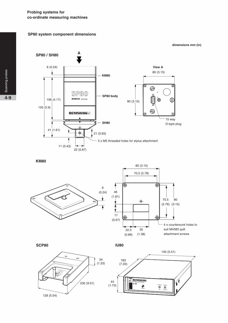
4-9
Sca
nnin
g pr
obes
KM80
IU80SCP80
128 (5.04)
230 (9.01)
34(1.33)
44(1.73)
183(7.20)
140 (5.51)
17
(0.67)
6
(0.24)
22.5
(0.89)
35
(1.38)
80 (3.15)
70.5 (2.78)
4 x countersunk holes to
suit M4/M3 quill
attachment screws
22 (0.87)
A
6 (0.24)
11 (0.43)
21 (0.83)
5 x M5 threaded holes for stylus attachment
150 (5.9)
106 (4.17)
41 (1.61)
View A
15 way
D-type plug
80 (3.15)
80 (3.15)
SP80 / SH80
dimensions mm (in)
SP80 system component dimensions
46
(1.81)80
(3.15)
70.5
(2.76)
KM80
SP80 body
SH80

Specification summary SP80
PROBE ATTRIBUTES Ultra-high accuracy scanning probe with three axis measurement (X, Y, Z)
ORIENTATION Vertical
SIZE 80 mm (3.15 in) square body, 150 mm (5.9 in) long including stylus holder
QUILL MOUNTING 80 mm (3.15 in) kinematic quill mount (KM80) as standard
Shank mount (SM80) and other custom made adaptor plates available
- contact your nearest Renishaw supplier for details
MEASUREMENT RANGE ±2.5 mm (±0.12 in) X, Y, Z (three axis measurement)
OVERTRAVEL RANGE X and Y protected by a kinematic break out joint on SH80
+Z has a mechanical ‘bump-stop’
RESOLUTION OF SCALES 0.02 µm (0.00000079 in)
SPRING RATE Approximately 1.8 N/mm (X, Y, Z)
WEIGHT SP80 probe: 860 g (30.33 oz) excluding mount and stylus holder
SH80 stylus holder: 185 g (6.5 oz)
KM80 quill mount: 110 g (3.88 oz)
PULL OFF FORCE OF MODULE < 20 N when using SCP80, otherwise approximately 80 N
PROBE POWER SUPPLY +9 V to +18 V, max 300 mA dc
SYSTEM POWER SUPPLY (inc. IU80) +5 V ±0.25 V @ 1 A max dc
SP80 PROBE OUTPUTS (X, Y, Z) 1.5 V ±0.25 V p-p. analogue quadrature signal (about 2.5 V Ref.)
INTERFACING OPTIONS The options are:
• Using an SP80 daughtercard for direct UCC1 or UCC2 integration
• Using a Renishaw PCI counter card (CC6) and the Renishaw interpolator
unit (IU80)
• Using an interface card designed by the machine builder and used in
conjunction with an IU80
• Using a countercard and interpolator unit designed by the machine builder.
CHANGE RACK SYSTEM SCP80 single port unit(s) mounted to the MRS
Sca
nnin
g pr
obes
4-10
SP80 features and benefits:
••••• Ultra-high accuracy measurement, provided by digital scale and readheads
••••• Long styli carrying capability for access to deep features
••••• Isolated optical metrology for direct accurate measurement of stylus deflection
••••• Kinematic stylus changing for system flexibility
••••• Low inertia mechanism for excellent dynamic response
••••• Bump-stop crash protection in the Z axis, together with a detachable stylus holder for
XY crash protection
••••• No motors, therefore improved thermal stability and reliability

Probing systems forco-ordinate measuring machines
107.
5 m
m (
4.23
in)
Ø50 mm
(1.97 in)
1.5 mm
(0.06 in)
Ø50 mm
(1.97 in)
89 m
m (
3.5
in)
1.5 mm (0.06 in)
1.5 mm
(0.06 in)
12.5 mm
(0.5 in)
SP600Q
12.5 mm
(0.5 in)
60 mm square
(2.4 in square)
SP600
SP600M
SP600, SP600M and SP600Qscanning probes
The SP600 (shank mounting), SP600M (multi-wired autojoint
mounting) and SP600Q (fixed in-quill mounting) are highly
reliable analogue probes which are ideal for profile scanning
and measurement on CMMs.
The SP600 family of scanning probes allow large amounts of
data to be rapidly gathered for inspection and digitising
purposes. Axis movement in each direction (X, Y and Z) is
±1 mm (±0.04 in) (in all orientation positions on a PH10) and
stylus lengths up to 300 mm (11.81 in) can be used with the
SH600 stylus holder.
The SH600 provides overtravel protection, and allows rapid
and repeatable interchange between stylus configurations.
This can be automated by using the SCR600 stylus change
rack or alternatively, individual SCP600 stylus change ports
mounted to a MRS.
The probe design gives an excellent self centring figure of
<5 µm (<0.0002 in); a measure of its ability to return to zero
mechanically when not in contact with the part. This low
figure, although irrelevant to the probe’s accuracy, enables
the use of small deflections and therefore low contact forces.
The probe output always gives its precise position relative to
the probe body.
Low mass, high structural stiffness and friction-free viscous
damping give excellent dynamic performance characteristics.
SP600 probeThe SP600 allows simple fixed mounting via a Renishaw
shank.
SP600M probeThe SP600M is mounted via an autojoint and can therefore
be orientated by use with Renishaw’s PH10M or PH10MQ
motorised probe heads. Rapid interchange with other
autojoint probes is possible by using a Renishaw ACR1 or
ACR3 autochange rack system.
68 m
m (
2.68
in)
1.5 mm
(0.06 in)
12.5 mm
(0.5 in)
4-11
Sca
nnin
g pr
obes
SP600Q probeCompact in size, the SP600Q mounts directly onto the quill of
the CMM. Together with the significant reduction in size, the
SP600Q provides a more cost-effective scanning option to
CMM users with small working area requirements.
CAUTIONWhen using a SP600M with a PH10MQ a PEM25
extension bar is required to achieve A = 97.5° or
A = 105° in all B-axis postions.
SH600
SH600
SH600

Sca
nnin
g pr
obes
4-12
SH600 STD / SH600 EXT stylus holdersThe SH600 stylus holder provides overtravel
protection, and allows rapid and repeatable
interchange between stylus configurations. This
can be automated by using the SCR600 stylus
change rack or, alternatively, individual SCP600
stylus change ports mounted on a MRS.
There are two variants, SH600 STD and SH600
EXT, the difference being the stylus carrying
capacity. The STD can carry up to 200 mm
(7.87 in) and the EXT up to 300 mm (11.9 in)
long stylus.
SCR600 stylus change rackThe SCR600 is a passive stylus change rack for
use with the SP600 probe family, and requires
no electrical connections. It is protected from
overtravel (in the probe entry direction) by a
mechanism in the base which can be manually
reset. It houses up to four SH600 stylus holders
per rack and any number of racks can be used in
a system.
SCP600 stylus change portThe SCP600 has passive operation like the
SCR600 and mounts on the MRS. This allows
flexibility for users to configure multiple ports, to
suit the application.SCP600 portsmount to MRS
SCP600
SH600
SCR600
MRS
Ø55 mm (Ø2.17 in)
225
mm
(8.
86 in
)
235 mm (9.25 in)
31.5
mm
(1.
24 in
)

Probing systems forco-ordinate measuring machines
4-13
Sca
nnin
g pr
obes
SP600 family features and benefits:
• High speed scanning up to 300 mm/s (11.8 in/s),
fast point measurement and high frequency response
• Low probing forces give maximum application
flexibility
• Three variants; SP600, SP600M and SP600Q
allows the ideal probe match to suit the CMM
• Extremely robust design will withstand moderate
collisions
• Fast interchange between stylus configurations
permits the best solution for the application and
increases productivity - automatic changing with
either SCR600 or SCP600 mounted on MRS
• Compatible with Renishaw’s autochange rack
systems to allow changing between Renishaw’s
other probes fitted with an autojoint
• Excellent product life with a MTBF in excess of
50,000 hours gives low cost of ownership
Specification summary SP600, SP600M and SP600Q
PRINCIPAL APPLICATION High speed, contact form scanning and fast point measurement applications
PROBE ATTRIBUTES 3 axis measurement X, Y, Z
Linear and parallel motion in all axes
MEASUREMENT RANGE ±1 mm (±0.04 in) X, Y, Z in any attitude using a 300 mm (11.8 in) stylus
OVERTRAVEL RANGE ±X, ±Y and -Z are protected by a kinematic break out joint on the SH600
+Z is protected by a bump-stop design
RESOLUTION 0.1 µm (0.000004 in) with optional AC2 interface card
1.0 µm (0.00004 in) with optional AC1 interface card
SPRING RATE 1.2 N/mm (7.05 ozf) nominal (X,Y,Z)
STYLI Thread M4 standard range
Length 200 mm (7.87 in) maximum using SH600 STD
300 mm (11.8 in) maximum using SH600 EXT
Mass 20 g (0.7 oz) maximum
POWER SUPPLY +12 V to -12 V, 5 V (±10%)
OUTPUTS (X, Y, Z) Analogue proportional
Voltage output scaling: 4 V/mm to 8.5 V/mm (dependant on stylus)
WEIGHT SP600 172 g (6.1 oz) excluding shank
SP600M 216 g (7.6 oz)
SP600Q 299 g (10.5 oz)
MOUNTING SP600 Adaptors to suit clutch, shank adaptor or CMM shank
SP600M Multiwired autojoint
SP600Q Direct quill mounting to the CMM
SUITABLE INTERFACE Directly into UCC or
AC1 or AC2 interface cards (ISA bus)
CHANGING RACK OPTIONS SCR600 4 port rack
SCP600 single port unit(s) mounted to the MRS


Probing systems forco-ordinate measuring machines
Q24885
M3 / M2
adaptor
PAA
PH1 *
M2 thread styli
MIH
or
MIHS
TP20 TP2-5W TP200 ‡ * TP6
5-1
Man
ual p
robe
hea
dsw
ith in
tegr
al M
8/au
tojo
int p
robe
mou
nt
Manual probe heads
PK1 PEL1 PEL2 PEL3 PAA2 PAA3
PH6 **

M3 thread styli M4 thread styli
* PH1 is not compatible with TP200
** PH6 has integral cable
† Compatible with multiwired systems
(TP7M, SP600M and SP25M)
‡ Specialised interface required
PH6M †
TP6A SP25M ‡ TP7M ‡
M4 / M3
adaptor
SP600M ‡
PEM25 PEM1 PEM2 PEM3 PEM25 PEM1
Man
ual p
robe
hea
dsw
ith in
tegr
al M
8/au
tojo
int p
robe
mou
nt
5-2

Probing systems forco-ordinate measuring machines
* MH20/MH20i are covered in
section 6
5-3
Man
ual p
robe
hea
dsw
ith in
tegr
al M
8/au
tojo
int p
robe
mou
nt
MH8
PEL1
M2 thread styli M3 thread styli
M3 / M2
adaptor
LF EF MF SF 6WEM1 EM2
STD STD
TP2-5W TP20 NI
MH20 *
MH20i *
TP1S

Specification summary MIH and MIH-S
PROBE MOUNTING Autojoint (Note: There is no multiwire capability)
PROBE STATUS INDICATION LED
CABLE CONNECTION MIH - 5 pin DIN 180 socket MIH-S - 12 pin Hirose
A AXIS INDEXING 0° to 105° in 7.5° steps = 15 positions
B AXIS INDEXING ±180° in 7.5° steps = 48 positions
WEIGHT 580 g (20.5 oz)
REPEATABILITY OF POSITION (2σ) 1 µm (0.00004 in) when used with a TP6A and 21 mm (0.83 in) stylus
MAXIMUM EXTENSION BAR 300 mm (11.8 in)
MAXIMUM RECOMMENDED TORQUE 0.45 Nm
SUITABLE PROBE INTERFACE PI 4-2, PI 200 or PI 7-2
MIH-S HEAD INTERFACE Uses MIH-SI interface (RS232 communication)
The MIH is a versatile manual indexing probe
head. It has programmable indexing positions
using 7.5° increments and has an autojoint
probe mount for fast repeatable probe
changing. These features can increase the
productivity of a manual CMM.
The MIH-S is an enhanced version of the
MIH which enables the feedback of positional
status to the PC over an RS232 serial
communication link, via the MIH-SI interface.
This enables the CMM computer to:
• Verify that the MIH-S has been moved to
the correct position and locked into place.
• Identify the locked position of the MIH-S.
Measurement performance, functionality and
dimensions are the same as for the MIH.
MIH features and benefits:
• Repeatable indexing in 720 positions
• An integral LCD enables easy
programming of probe orientation positions
• 20 probe positions can be memorised
• Compatible with most Renishaw probes
(excluding all multi-wire e.g. TP7M)
• Capable of carrying up to 300 mm (11.81 in)
extension for deep part measurement
MIH
MIH-S
62 mm
(2.44 in)R 62.5 mm
(2.46 in)
5.0 mm
(0.19 in)
102
mm
(4.
0 in
)
76 m
m (
3.0
in)
MIH manual indexingprobe head
MIH-S manual indexingprobe head M
anua
l pro
be h
eads
with
inte
gral
M8/
auto
join
t pro
be m
ount
5-4
MIH / MIH-S
Please refer to page 5-3 for probe
compatibility information

Probing systems forco-ordinate measuring machines
69 m
m (
2.52
in)
The MH8 is a compact, indexing probe head
that is designed for use on small manual CMMs.
It is compatible with TP20, TP6 and TP2 probes.
MH8 features and benefits:
• Universal M8 thread for probe connection
• Repeatable indexing in 168 positions
• The CMM operator need only qualify the
required probe positions once during set up
• 50 mm (1.97 in) probe extension bar can
be fitted to extend measurement capability
Ø48 mm
(1.89 in)
R 70.0 mm
(2.76 in)
43 m
m (
1.69
in)
5.7 mm (0.23 in)
Specification summary MH8
PROBE MOUNTING M8 thread
PROBE STATUS INDICATION 1 LED
CABLE CONNECTION 5 pin DIN 180° socket
A AXIS INDEXING 0° to 90° in 15° repeatable steps = 7 positions
B AXIS INDEXING ±180° in 15° repeatable steps = 24 positions
WEIGHT 205 g (7.2 oz)
REPEATABILITY OF POSITION (2σ) 1.5 µm (0.00006 in) TP2 and 10 mm (0.39 in) stylus fitted
MAXIMUM EXTENSION BAR 50 mm (1.96 in) PEL1 only
SUITABLE PROBE INTERFACE PI 4-2, PI200
MH8 manual indexingprobe head
5-5
Man
ual p
robe
hea
dsw
ith in
tegr
al M
8/au
tojo
int p
robe
mou
nt
Please refer to page 5-3 for probe
compatibility information

Man
ual p
robe
hea
dsw
ith in
tegr
al M
8/au
tojo
int p
robe
mou
nt
5-6
Specification summary PH6 PH6M
PROBE MOUNTING M8 thread Autojoint (full multi-wire capability)
PROBE STATUS INDICATION 1 LED 1 LED
CABLE CONNECTION Hard wired 5 core cable Micro ‘D’ connector for multi-wire cable fitment
WEIGHT * 48 g (1.76 oz) 160 g (6.1 oz)
PROBE CHANGE REPEATABILITY (2σ) N/A 1 µm (0.00004 in) at 50 mm (1.97 in) from autojoint
SUITABLE PROBE INTERFACE PI 4-2, PI 200 PI 4-2, PI 200, PI 7-2
* Excluding shank & cable
A compact, vertical probe head with a mount
for M8 thread probes.
PH6M features and benefits:
• Fixed, vertical probe head
• Autojoint for fast, repeatable probe
changing
• Compatible with the complete
Renishaw multi-wire probe range
and standard probes with autojoint
adaptors and extension bars
PH6 features and benefits:
••••• Universal M8 thread for probe connection
• Shank mounted
• Integral cable
• Simple to fit to a CMM
The PH6M is the multi-wired version of the
PH6 and is fitted with an autojoint.
Ø60 mm
(2.36 in)
28 m
m
(1.1
in)
Ø19 mm
(0.75 in)
40 m
m
(1.5
7 in
)
PH6 fixed probe head
PH6M fixed probe head
Please refer to page 5-3 for probe
compatibility information

Probing systems forco-ordinate measuring machines
Specification summary PH1
PROBE MOUNTING M8 thread (excluding TP200)
PROBE STATUS INDICATION 1 LED
CABLE CONNECTION 5 pin DIN 180° socket
OVERTRAVEL BREAK LOADAdjustable from 0.2 N to locked solid
A AXIS ARTICULATION Swivel of ±115° locked with hexagonal key (3 mm A/F)
B AXIS INDEXING 15° steps through 360° (non-repeatable)
WEIGHT * 125 g (0.28 lb)
SUITABLE PROBE INTERFACE PI 4-2
* Excluding shank & cable
A manual probe head with non-repeatable
indexing in the B axis and ±115° rotation in
the A axis. The probe is shank mounted to the
CMM.
PH1 features and benefits:• Adjustable in both the A and B axes
• Limited overtravel protection
• M8 thread probe mount that is offset
from the mounting shank Z-axis
PH1 manual articulatingprobe head
5-7
Man
ual p
robe
hea
dsw
ith in
tegr
al M
8/au
tojo
int p
robe
mou
nt
Please refer to page 5-3 for probe
compatibility information
A axis
±115°
26 m
m (
1.02
in)
40 m
m (
1.57
in)
17 mm
(0.6 in)
Ø40 mm (1.57 in)

The MH20 is a compact probe head with fully
adjustable orientation.
The integral TP20 kinematic stylus module mount
enables repeatable stylus module changing,
without the need for re-qualification, providing head
adjustment has not taken place. It is compatible
with the full range of TP20 stylus modules, which
comprises 5-way module versions with either
length or trigger force options, plus a 6-way
module. Multiple stylus configurations are easily
interchanged allowing quick and easy access to
work piece features.
The head is pre-mounted with a customer-specified
shank to suit the CMM and features a red LED
which indicates probe status.
MH20 features and benefits:
• Fast repeatable stylus module changing to
improve productivity
• Ultra compact design that maximises CMM
working volume
• Infinite positioning within the range of the
head to optimise access to complex parts.
• TP20 compatibility ensures a wide range
of stylus configurations are easily
interchanged enhancing flexibility
Specification summary MH20
PROBE MOUNT TP20 kinematic
PROBE STATUS INDICATION 1 LED
CABLE CONNECTION 5 pin DIN socket
RANGE OF ARTICULATION A axis ±93°
B axis ±300°
MAXIMUM LOAD EM2 extended module - 94.5 mm (3.72 in)
WEIGHT WITHOUT SHANK 100 g (3.53 oz)
MOUNTING MS/T range of shanks
DUAL AXES LOCK Single rotary thumbwheel
OPERATING TEMPERATURE RANGE 10 °C to 40 °C (50 °F to 104 °F)
STORAGE TEMPERATURE RANGE -10 °C to 70 °C (14 °F to 158 °F)
SUITABLE PROBE INTERFACE PI 4-2
Note: The MH20 is compatible with the MSR1 module storage rack, but not with the MCR20 module change rack.
MH20 manual articulatingprobe head with integral TP20module mount
6-1
Man
ual p
robe
hea
dsw
ith in
tegr
al T
P20
sty
lus
mod
ule
mou
nt
Please refer to page 5-3 for probe
compatibility information
73 m
m (
2.87
in)
Ø31 mm (1.24 in)
47 m
m (
1.85
in)
A axis ±93°
B axis ±300°

Probing systems forco-ordinate measuring machines
6-2
Man
ual p
robe
hea
dsw
ith in
tegr
al T
P20
sty
lus
mod
ule
mou
nt
The MH20i is a manual probe head with two axis adjustable
indexing. Compact in design, it features an integral TP20 kinematic
mount that enables repeatable stylus module changing without the
need for re-qualification.
The MH20i offers 168 repeatable index positions which are set at
15° increments to maximise flexibility and productivity. Easy to read
scales permit rapid re-orientation to pre-qualified positions, and its
lock/unlock feature allows ease of positioning and eliminates
unnecessary wear.
It is compatible with the full range of TP20 stylus modules, which
comprises 5-way module versions with either length or trigger force
options, plus a 6-way module. Multiple stylus configurations are
easily interchanged allowing quick and easy access to work piece
features.
Specification summary MH20i
PROBE MOUNT TP20 kinematic
POSITIONAL REPEATABILITY (2σ) 1.5 µm (0.00006 in) at stylus tip with TP20 SF stylus module and 10 mm (0.39 in) styli
POSITIONAL REPEATABILITY (2σ) 2.5 µm (0.0001 in) at stylus tip with TP20 EM2 stylus module and 20 mm (0.78 in) styli
PROBE STATUS INDICATION 1 LED
CABLE CONNECTION 5 pin DIN socket
A AXIS INDEXING 0° to 90° in 15° repeatable steps = 7 positions
B AXIS INDEXING ±180° in 15° repeatable steps = 24 positions
MAXIMUM LOAD EM2 extended module – 94.5 mm (3.72 in)
WEIGHT WITHOUT SHANK 210 g (7.41 oz)
MOUNTING MS range of shanks
DUAL AXES LOCK Single lock lever
OPERATING TEMPERATURE RANGE 10 °C to 40 °C (50 °F to 104 °F)
STORAGE TEMPERATURE RANGE -10 °C to +70 °C (14 °F to 158 °F)
SUITABLE PROBE INTERFACE PI 4-2
Note: The MH20i is compatible with the MSR1 module storage rack, but not with the MCR20 module change rack.
MH20i features and benefits:
• Enhanced inspection capability from adjustable probe
orientation with 168 repeatable index positions set at
15° increments
• Repeatable TP20 stylus module changing in each
pre-qualified position without the need for
re-qualification significantly enhances productivity
• TP20 compatibility, providing a wide range of force
and length options to optimise machine performance
and access capability
• Easy-to-read scales allow rapid re-orientation
MH20i manual indexing probe headwith integral TP20 module mount
Please refer to page 5-3 for probe
compatibility information
5.7 mm(0.22 in)
A axis 0°- 90°
61 m
m (
2.4
in)
Ø48 mm (1.89 in)
B axis ±180°
37 m
m (
1.45
in)


Probing systems forco-ordinate measuring machines
KM2 kinematic
mount
HA-8
arm probe
HA-M
arm probe
Integral overtravel protection unit
PHS1 head
The Renishaw servo positioning head (PHS1)
is a two axis motorised head with continuous
servo drive enabling the probe configuration to
be positioned at almost any angle.
The PHS1 has been designed to meet the
demanding requirements of “body in white”
measurement where fine angular positioning
and long reach are needed.
KM1 kinematic
mount
HE330/
500/750
arm probe
7-1
Mot
oris
ed p
robe
hea
dsS
ervo
type
PHS1 motorised (servotype) probe head

M2 thread styli M3 thread styli
PHS1 head
HE 750 HE 500 HE 330
PEL4 PEL3 PEL2 PEL1 PAA3 PAA2 PAA1
TP20 TP2
M3 / M2
adaptor
TP6
HA-8 HA-M
M8 multiwire
adaptor adaptor
Mot
oris
ed p
robe
hea
dsS
ervo
type
7-2

Probing systems forco-ordinate measuring machines
PHS1 head kitThe PHS1 head is not locked into position in
the same manner as an indexing head.
Instead, it is driven to approximately the
required position and when a probing point is
taken, the axes of the head latch
simultaneously with the axes of the CMM to
give accurate probe readings.
The PHS1 head is controlled directly via a PC
interface card in the CMM controller, and
requires full integration by the equipment
supplier. Full information is given in the PHS1
Programmers guide (PD-2100-9015).
A range of different probes can be fitted and
automatically exchanged. These include
touch trigger probes and non-contact
scanning probes.
Extra long extensions allow the Renishaw
trigger probes to measure otherwise
inaccessible features.
A kinematic mount (KM1/KM2) allows quick
fixing of the head to the machine and fast
changeover to other heads.
PH10M or PH10T heads can be fitted (via a
PHA1, PHA2 or a PHA3 probe head adaptor -
details on request) instead of PHS1 in
applications where existing parts need to be
inspected without the need to re-write the
programs for PHS1.
The head is protected by a built-in overtravel
protection unit that can be configured to stop
the machine in the event of a collision.
An air supply to the head is recommended for
axis motor cooling and optimum metrology
performance.
Ø90 mm
(3.54 in)
49.75 mm
(1.96 in)
247 mm (9.72 in)
Ø10
0 m
m (
3.94
in)
7-3
Mot
oris
ed p
robe
hea
dsS
ervo
type

Specification summary PHS1
OPERATING TEMPERATURE 15 °C to 40 °C (50 °F to 104 °F)
WEIGHT (inc. probe extension and kinematic joint) <3 kg (<6.61 lb)
CARRYING CAPABILITY Combined probe and extension mass of 1 kg (2.20 lb)
MAXIMUM TORQUE 2 Nm
MECHANICAL CLUTCH SLIP 3 Nm ±0.5 Nm
MOVEMENT SPEED 150°s-1 maximum, 120°s-1 typical
ARM ROTATION ANGLE D axis ±184°
E axis ±184°
ANGULAR RESOLUTION 0.2 arc sec (equivalent to 0.1 µm at 100 mm radius)
COLLISION PROTECTION Signal for head protection with kinematic overtravel unit
SUITABLE HEAD INTERFACE PC interface card and UCC2 controller
CHANGE RACK SYSTEM ACR2
ACR2 port pair kit
The ACR2 autochange rack is an extension arm
changing system for the PHS1 servo positioning
head system.
It allows probe extensions or probe adaptors to
be exchanged to suit the probing task required
without manual intervention.
Its modular construction and simple operation
enable any number of racks to be positioned on
a pillar within the machine volume.
The rack is passive, all locking and unlocking of
adaptors and extensions is done by the motion
of the CMM.
PHS1 system features and benefits:
• Repeatable exchange of PHS1 probe
heads via KM1/KM2
• Easy interchange with Renishaw’s
PH10M/T motorised head systems
• Two-axis servo operated with
±184° variable positioning capability
in both axes
• Orientation to almost any angle
• Long reach up to 750 mm (29.53 in)
• Automatic probe changing
• Accommodation of a range of sensors –
trigger probes and non-contact
scanning probes
Mot
oris
ed p
robe
hea
dsS
ervo
type
7-4
ACR2

Probing systems forco-ordinate measuring machines
The PH10T is a motorised indexing head that
mounts and re-orientates the probe. The PH10T
can be repeatably orientated to any one of 720
positions.
All M8 thread probes can be fitted directly onto
the mount of the PH10T. The PH10T is
operated by the PHC10-2 and is compatible
with other Renishaw M8 threaded products.
The AM1 adjustment module permits the
correction of the alignment of the probe head to
the machine and is fitted between the head and
the shank.
PH10T features and benefits:
• Compatible with M8 thread probes
• Compatible with PEL range of extension
bars up to 300 mm (11.81 in) long
• 720 repeatable positions at 7.5° increments
• Shank-mounted
8-1
Mot
oris
ed p
robe
hea
dsIn
dexi
ng ty
pe
PH10T motorised indexingprobe head
Specification summary PH10T
REPEATABILITY OF POSITION* (2σ) <0.5 µm (<0.00002 in) specified at a distance of 48 mm (1.89 in)
*At constant temperature - equivalent to a TP2 and PS1R stylus
ACCURACY OF STEP SPACING ±0.24 mm (0.009 in) using TP6 and 21 mm stylus (A-5000-5335)
FROM THEORETICAL POSITION
CYCLE TIME 7.5° STEP 2.5 seconds
MAXIMUM 90° MOVE 3.5 seconds
TOTAL ANGULAR A AXIS 0° to 105° in 7.5° steps
MOVEMENT B AXIS ±180° in 7.5° steps
TOTAL NUMBER OF POSITIONS 720
MAXIMUM OUTPUT TORQUE 0.45 Nm
MAXIMUM EXTENSION BAR LENGTH 300 mm (11.8 in)
(WITH TP2/TP200)
HEAD MOUNTING Shank to suit CMM (MS range)
WEIGHT (excluding shank) 645 g (22.7 oz)
WORKING TEMPERATURE RANGE 10 °C to 40 °C (50 °F to 104 °F)
PROBE MOUNTING FACILITY M8 thread
PROBE HEAD CONTROLLER PHC10-2
HAND HELD CONTROL UNIT HCU1
62 mm (2.44 in)
25 mm (0.98 in)
102
mm
(4.
0 in
)
B axis
A axis

Mot
oris
ed p
robe
hea
dsIn
dexi
ng ty
pe
8-2
Shank
AM1
PH10T
M3 thread styli M2 thread styli
PEL1 PEL2 PEL3 PEL4
M3 / M2
adaptor
‡ Specialised interface required
TP6
TP20 TP2-5W TP200 ‡
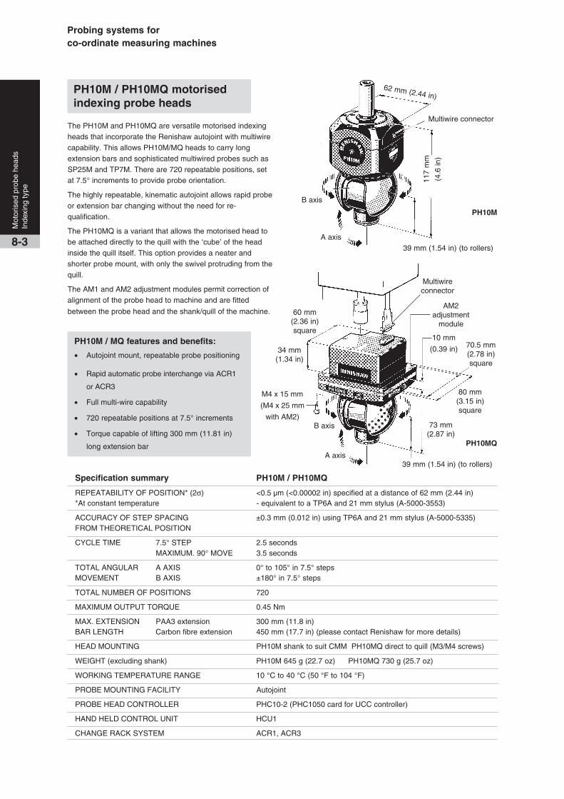
Probing systems forco-ordinate measuring machines
8-3
Mot
oris
ed p
robe
hea
dsIn
dexi
ng ty
pe
PH10M / PH10MQ motorisedindexing probe heads
The PH10M and PH10MQ are versatile motorised indexingheads that incorporate the Renishaw autojoint with multiwirecapability. This allows PH10M/MQ heads to carry longextension bars and sophisticated multiwired probes such asSP25M and TP7M. There are 720 repeatable positions, setat 7.5° increments to provide probe orientation.
The highly repeatable, kinematic autojoint allows rapid probeor extension bar changing without the need for re-qualification.
The PH10MQ is a variant that allows the motorised head tobe attached directly to the quill with the ‘cube’ of the headinside the quill itself. This option provides a neater andshorter probe mount, with only the swivel protruding from thequill.
The AM1 and AM2 adjustment modules permit correction ofalignment of the probe head to machine and are fitted
between the probe head and the shank/quill of the machine.
PH10M / MQ features and benefits:
• Autojoint mount, repeatable probe positioning
• Rapid automatic probe interchange via ACR1
or ACR3
• Full multi-wire capability
• 720 repeatable positions at 7.5° increments
• Torque capable of lifting 300 mm (11.81 in)
long extension bar
PH10M
62 mm (2.44 in)
B axis
Multiwire connector
117
mm
(4.6
in)
A axis39 mm (1.54 in) (to rollers)
PH10MQ
39 mm (1.54 in) (to rollers)
73 mm(2.87 in)
70.5 mm(2.78 in)square
80 mm(3.15 in)square
10 mm
(0.39 in)
A axis
60 mm(2.36 in)square
34 mm(1.34 in)
B axis
M4 x 15 mm
(M4 x 25 mm
with AM2)
AM2adjustment
module
Multiwireconnector
Specification summary PH10M / PH10MQ
REPEATABILITY OF POSITION* (2σ) <0.5 µm (<0.00002 in) specified at a distance of 62 mm (2.44 in)*At constant temperature - equivalent to a TP6A and 21 mm stylus (A-5000-3553)
ACCURACY OF STEP SPACING ±0.3 mm (0.012 in) using TP6A and 21 mm stylus (A-5000-5335)FROM THEORETICAL POSITION
CYCLE TIME 7.5° STEP 2.5 secondsMAXIMUM. 90° MOVE 3.5 seconds
TOTAL ANGULAR A AXIS 0° to 105° in 7.5° stepsMOVEMENT B AXIS ±180° in 7.5° steps
TOTAL NUMBER OF POSITIONS 720
MAXIMUM OUTPUT TORQUE 0.45 Nm
MAX. EXTENSION PAA3 extension 300 mm (11.8 in)BAR LENGTH Carbon fibre extension 450 mm (17.7 in) (please contact Renishaw for more details)
HEAD MOUNTING PH10M shank to suit CMM PH10MQ direct to quill (M3/M4 screws)
WEIGHT (excluding shank) PH10M 645 g (22.7 oz) PH10MQ 730 g (25.7 oz)
WORKING TEMPERATURE RANGE 10 °C to 40 °C (50 °F to 104 °F)
PROBE MOUNTING FACILITY Autojoint
PROBE HEAD CONTROLLER PHC10-2 (PHC1050 card for UCC controller)
HAND HELD CONTROL UNIT HCU1
CHANGE RACK SYSTEM ACR1, ACR3

8-4
Mot
oris
ed p
robe
hea
dsIn
dexi
ng ty
pe
Shank
AM1
PH10M
AM2
PH10MQ *
‡ Specialised interface required
* NOTE: When using a SP600M with a PH10MQ
a PEM25 extension bar is required to achieve
A = 97.5° or A = 105° in all B-axis postions
M2 thread styli M3 thread styli M4 thread styli
PAA1
PAA3 PAA2
PEM25 * PEM1 PEM2 PEM3 PEM25 *
M3 / M2
adaptor
M4 / M3
adaptor
TP20 TP2-5W TP200‡
PEL3 PEL2 PEL1
SP25 ‡
TP6
SP600M ‡ *
TP6A TP7M ‡
Note: Please see the accessories page 13-4
for details of adaptor plates PHA3 and PHA80
which permit rapid interchange between
PH10MQ and SP80 scanning probe.
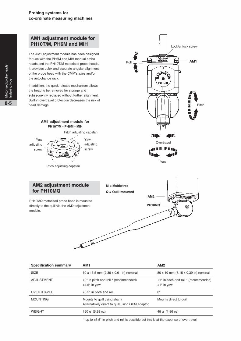
Probing systems forco-ordinate measuring machines
PH10MQ motorised probe head is mounted
directly to the quill via the AM2 adjustment
module.
M = Multiwired
Q = Quill mounted
* up to ±5.5° in pitch and roll is possible but this is at the expense of overtravel
Specification summary AM1 AM2
SIZE 60 x 15.5 mm (2.36 x 0.61 in) nominal 80 x 10 mm (3.15 x 0.39 in) nominal
ADJUSTMENT ±2° in pitch and roll * (recommended) ±1° in pitch and roll * (recommended)
±4.5° in yaw ±1° in yaw
OVERTRAVEL ±3.5° in pitch and roll 0°
MOUNTING Mounts to quill using shank Mounts direct to quill
Alternatively direct to quill using OEM adaptor
WEIGHT 150 g (5.29 oz) 48 g (1.96 oz)
The AM1 adjustment module has been designed
for use with the PH6M and MIH manual probe
heads and the PH10T/M motorised probe heads.
It provides quick and accurate angular alignment
of the probe head with the CMM’s axes and/or
the autochange rack.
In addition, the quick release mechanism allows
the head to be removed for storage and
subsequently replaced without further alignment.
Built in overtravel protection decreases the risk of
head damage.
Yaw
adjusting
screw
Pitch adjusting capstan
Pitch adjusting capstanYaw
Pitch
Lock/unlock screw
Overtravel
8-5
Mot
oris
ed p
robe
hea
dsIn
dexi
ng ty
pe
AM1 adjustment module forPH10T/M - PH6M - MIH
AM1 adjustment module forPH10T/M, PH6M and MIH
AM2 adjustment modulefor PH10MQ
AM2
PH10MQ
Roll
Yaw
adjusting
screw
AM1
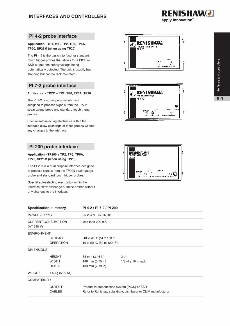
INTERFACES AND CONTROLLERS
Specification summary PI 4-2 / PI 7-2 / PI 200
POWER SUPPLY 85-264 V 47-66 Hz
CURRENT CONSUMPTION less than 200 mA
(AT 240 V)
ENVIRONMENT
STORAGE -10 to 70 °C (14 to 158 °F)
OPERATION 10 to 50 °C (50 to 122 °F)
DIMENSIONS
HEIGHT 88 mm (3.46 in) 2’U’
WIDTH 146 mm (5.75 in) 1/3 of a 19 in rack
DEPTH 183 mm (7.19 in)
WEIGHT 1.6 kg (55.9 oz)
COMPATIBILITY
OUTPUT Product interconnection system (PICS) or SSR
CABLES Refer to Renishaw subsidiary, distributor or CMM manufacturer
9-1
Inte
rfac
es a
nd c
ontr
olle
rs
PI 4-2 probe interface
Application - TP1, MIP, TP2, TP6, TP6A,
TP20, SP25M (when using TP20)
The PI 4-2 is the basic interface for standard
touch trigger probes that allows for a PICS or
SSR output, the supply voltage being
automatically detected. The unit is usually free
standing but can be rack mounted.
PI 7-2 probe interface
Application - TP7M + TP2, TP6, TP6A, TP20
The PI 7-2 is a dual purpose interface
designed to process signals from the TP7M
strain gauge probe and standard touch trigger
probes.
Special autoselecting electronics within the
interface allow exchange of these probes without
any changes to the interface.
PI 200 probe interface
Application - TP200 + TP2, TP6, TP6A,
TP20, SP25M (when using TP20)
The PI 200 is a dual purpose interface designed
to process signals from the TP200 strain gauge
probe and standard touch trigger probes.
Special autoselecting electronics within the
interface allow exchange of these probes without
any changes to the interface.

Probing systems forco-ordinate measuring machines
Specification summary PHC10-2
DATA TRANSMISSION RS232
IEEE (only available to special order)
USER DEFINABLE PARAMETERS
SERIAL Baud rate 300 - 19200
PARALLEL address, parallel poll bit
VOLTAGE RANGE 85-264 V 47/66 Hz
CURRENT CONSUMPTION (at 240 V) less than 500 mA
INPUT CONNECTORS 15 way ‘D’
PROBE OUTPUT CONNECTORS 7 pin DIN or 9 way ‘D’ type
DIMENSIONS HEIGHT 88 mm (3.46 in) 2 ‘U’
WIDTH 289.3 mm (11.4 in) 2/3 of a 19 in rack
DEPTH 220 mm (8.66 in)
WEIGHT 2.86 kg (101 oz)
MAXIMUM CABLE LENGTH 50 m (164 ft)
HAND HELD CONTROL UNIT HCU1 only
The HCU1 hand control and display unit is used
with the PHC10-2 to drive the PH10 probe head position.
It is useful for setting up a component,
operator controlled inspection and teach-cycle
programming. Features include two speed
action (jog and rapid move), two axis head
display, transmit button for teach cycle, status
and error LEDs.
Features
a) Manual control of head movements
b) LCD dot matrix showing : Head position,
system status, and error analysis.
The PHC10-2 head controller receives
instructions from the CMM controller and
controls the head functions and reports
system status to the CMM:
a) Drives PH10 to position sent either from
the HCU1 or CMM.
b) Checks and reports position.
c) Flags up errors e.g. failure to reach
position, obstruction before or after locking
etc. Probe triggering signals are routed
through the controller to the probe interface.
Inte
rfac
es a
nd c
ontr
olle
rs
9-2
PHC10-2 head controller
HCU1 hand held controlunit

9-3
Inte
rfac
es a
nd c
ontr
olle
rs
The IS1-2 interface selector is a fully automatic system for use
on CMM installations requiring multiple sensor types
(e.g. SP25M – scanning probe, TP7M – touch trigger probe,
OTP6M – optical trigger probe, etc). The unit functions by
identifying which probe has been fitted to the probe head and
switches the probe signal / power lines to the appropriate
interface.
The system comprises a standalone or rack-mountable
interface selector. The IS1-2 has four separate channel
outputs. These outputs allow any combination of the following
Renishaw probes to be integrated into one automated system:
••••• SP25M
••••• SP80
••••• SP600
••••• OTP6M*
••••• TP7M
••••• TP2/TP6/TP20/TP200*
* These probes can be incorporated into a multiple sensor
system consisting of any one of the other probe systems
specified without the necessity to use an IS1-2 unit.
Please contact Renishaw for further details.
IS1-2 interface selector
The IS1-2 is also fully compatible with Renishaw’s ACR1 and
ACR3 probe exchange systems, the PH10M range of
motorised heads and the PHS1 motorised servo head system
using the Renishaw product interconnection system (PICS).
A set of four programming modules are supplied pre-installed
within the IS1-2 unit which identify the probe in use. These
are TP7M, SP600M, SP80 and SP25M modules. The
remaining modules are supplied loose and can be installed by
the user. TP2, TP6, TP20, TP200 have an integral
identification system and therefore do not require a module.
Plugging the required product module into the respective
channel selector socket ensures that the probe connections
are made to the correct IS1-2 output port.
Third party probes, that carry the female autojoint, will require
specific identification resistors to be fitted within the female
autojoint. Special modules to permit the recognition of these
probes by the IS1-2 will also be required.

Probing systems forco-ordinate measuring machines
RenscanDC™ – the ultimate scanningperformance from your CMM
Renishaw’s patented RenscanDC™ system enables
measurement at extremely high speeds, but with the
accuracy of low speed measurement.
The traditional conflict between accuracy and scanning
speed is resolved by RenscanDC’s feature based
approach, which follows two steps:
1. Measure the feature at slow speed to establish an
accurate measurement. Repeat measurement at high
speed to identify errors introduced at high speed.
2. UCC2 automatically computes the dynamic error at
each point around the feature to derive a dynamic
correction map.
All subsequent parts can be measured at high speed and
the application of dynamic corrections will provide low-
speed accuracy at the fast measurement speeds.
9-4
Inte
rfac
es a
nd c
ontr
olle
rs
UCC2 universal CMMcontroller system
UCC2 features and benefits:
• Capable of smooth, fast and accurate blending of
CMM motion control
• Close integration between probing and the CMM
optimises system measuring performance
• Closed-loop known part scanning includes cylinder,
gasket and grid routines
• Available with three levels of operating capability:
touch-trigger probing, digitising and full scanning
capability including Renishaw’s patented
RenscanDC™
• Integrated control of all Renishaw standard touch
trigger probe systems and stylus changing
• Full future product compatibility using plug-in
daughtercards
• I++ DME server application
The UCC2 controller together with its associated products-
the SPA2 servo power amplifier and the MCU1 joystick, form
a comprehensive CMM control system. This system is a
sophisticated integrated motion controller that precisely
controls CMM motion, including comprehensive scanning
capabilities and automated probe calibration.
With UCC2 operating through an SPA2, the CMM motion
control is smooth, fast and accurate, permitting irregular
contours to be easily followed thanks to the ‘move blending’
software.
The UCC2 has three levels of operating capability: touch-
trigger probing, digitising and full scanning capability which
includes Renishaw’s patented RenscanDC™.
Future hardware and software upgrades can be carried out
easily, with function enhancements available by email or
telephone support. Software enhancements are simply
applied, as the control software is loaded at boot up.
Additional new products require only plug-in daughtercards.
All new probes and heads will be available with a controller
interface option that will also include any appropriate
calibration or set-up software.
The UCC2 controller is housed in a standard rack-mountable
enclosure and is connected to the host PC via a conventional
Ethernet link. It does not contain user application software.
The SPA2 servo power amplifier is housed in a standard
rack-mountable enclosure and the cables necessary to
connect it to the UCC2 are supplied as part of the kit.
The MCU1 machine control unit (joystick) is an ergonomically
designed unit suitable for both hand held or table based
operation. It is supplied with a 5-metre cable as standard but
other cable lengths or extensions can be used.
Scanning with UCC2
The UCC2 scanning capability provides a choice of scanning
techniques:
• Known part adaptive scanning, with sophisticated
scanning routines that include :
• Cylinder scan (a helical scan path that can adapt to
cones and spheres, as well as cylinders. It will also adapt
to out-of-round and out-of-position parts).
• Gasket scan (a known path scan constructed from a
series of lines and arcs).
• Grid scan (a 3D scan of a pre-defined area)
• Automatic find centre:- Utilisation of a scanning probe to
automatically find the centre of a groove or conical hole
• Advanced data filtering
• Advanced analogue probe calibration

UCC2 technical specification
• 19" 3U standard rack-mountable enclosure with 5
expansion slots for option cards and a 6th expansion
slot that conforms to the PCI specification.
• Simple Ethernet link to the PC via a crossover LAN
cable.
• Internal error-map
• 4-axis control.
• Scale inputs:- Renishaw RGH22, RGH24, RGH41 and
other digital scales are directly supported. Analogue
scales can be supported via an external interface.
• Uncommitted Binary I/O:- 6 inputs and 7 outputs
available as standard
• Comprehensive joystick interface
• TP20, TP200/SCR200, SP600 and
SP25M interfaces available as standard
• The following option cards are available :-
• SP80 interface
• PH10 motorised head interface
• PHS1 motorised head interface
• PICS/RS232 auxiliary product interface
• Additional axis; can be configured as a
rotary table or dual drive interface.
More than one can be fitted in a controller
• Temperature sensor inputs (24)
Operational
• Touch-trigger (standard)
• Digitising (optional upgrade)
• Scanning (optional upgrade), includes RenscanDC™
• I++DME server (optional upgrade)In
terf
aces
and
con
trol
lers
9-5
Specification summary UCC2
POWER SUPPLY 85 to 132 V ac, 170 to 264 V ac, 47 to 63 Hz, 150 W
ENVIRONMENT STORAGE -10 °C to 70 °C (14 °F to 158 °F)
OPERATION 10 °C to 50 °C (50 °F to 122 °F) local to UCC
DIMENSIONS HEIGHT 127 mm (5.0 in)
WIDTH 435 mm (17.1 in)
DEPTH 330 mm (129.9 in)
WEIGHT 8 kg (17 lb) - without cables and option boards
EMERGENCY STOP Category ‘2’ (subject to integration)
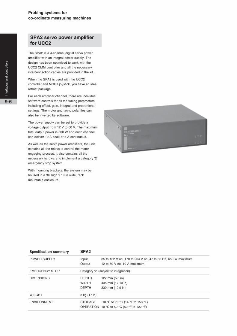
Probing systems forco-ordinate measuring machines
Inte
rfac
es a
nd c
ontr
olle
rs
9-6
The SPA2 is a 4-channel digital servo power
amplifier with an integral power supply. The
design has been optimised to work with the
UCC2 CMM controller and all the necessary
interconnection cables are provided in the kit.
When the SPA2 is used with the UCC2
controller and MCU1 joystick, you have an ideal
retrofit package.
For each amplifier channel, there are individual
software controls for all the tuning parameters
including offset, gain, integral and proportional
settings. The motor and tacho polarities can
also be inverted by software.
The power supply can be set to provide a
voltage output from 12 V to 60 V. The maximum
total output power is 600 W and each channel
can deliver 10 A peak or 5 A continuous.
As well as the servo power amplifiers, the unit
contains all the relays to control the motor
engaging process. It also contains all the
necessary hardware to implement a category ‘2’
emergency stop system.
With mounting brackets, the system may be
housed in a 3U high x 19 in wide, rack
mountable enclosure.
Specification summary SPA2
POWER SUPPLY Input 85 to 132 V ac, 170 to 264 V ac, 47 to 63 Hz, 650 W maximum
Output 12 to 60 V dc, 10 A maximum
EMERGENCY STOP Catagory ‘2’ (subject to integration)
DIMENSIONS HEIGHT 127 mm (5.0 in)
WIDTH 435 mm (17.13 in)
DEPTH 330 mm (12.9 in)
WEIGHT 8 kg (17 lb)
ENVIRONMENT STORAGE -10 °C to 70 °C (14 °F to 158 °F)
OPERATION 10 °C to 50 °C (50 °F to 122 °F)
SPA2 servo power amplifierfor UCC2

MCU1 multi-functional handcontrol unit
Inte
rfac
es a
nd c
ontr
olle
rs
9-7
The MCU1 is a multi-functional hand control unit that provides
complete CMM control.
Designed for use with the UCC range of controllers, the MCU1
is housed in an ergonomically styled enclosure that allows for
hand held (suitable for both right and left handed operators) or
table mounted operation.
The MCU1 is supplied as standard with a 5 metre cable, other
cable lengths and/or extensions can be used.
A large LCD screen gives status information and allows for
interaction with the metrology program.
The MCU1 can be used to:-
• Control the motion of your CMM’s axes
• Index your motorised head
• Operate your rotary table
• Operate as a computer mouse
• Allow navigation through operating software from its menu
system
• Customisation of part or all of the LCD screen is permitted
The control switches included on the MCU1 are as follows:
• An industry standard emergency stop switch
• A speed control that controls the move speeds in an
automatic move from 0 to 100%
• A “joystick enable” switch which can be programmed to
work in several modes including as a “dead-mans-handle”
• A 3-axis joystick
• Fast / slow joystick speed
• Individual axis locks
• “Start/stop program” switch
• “Engage servos” switch
• “Probe override” switch
• A “mode” switch to scroll through the various operating
modes:- CMM, motorised head, rotary table etc.
• An orientation switch that switches the joystick axes
around to suit the direction you are facing the machine
• Take point” (way point) switch
• “Cancel last point” switch
• An “axis system” switch that can switch joystick motion
between, machine, part and stylus co-ordinate systems
• Four uncommitted function switches F1 to F4
A MCU1 docking port is also available that allows the MCU1 to
be stored on the side of a cabinet, CMM bed or any other
non-horizontal surface.
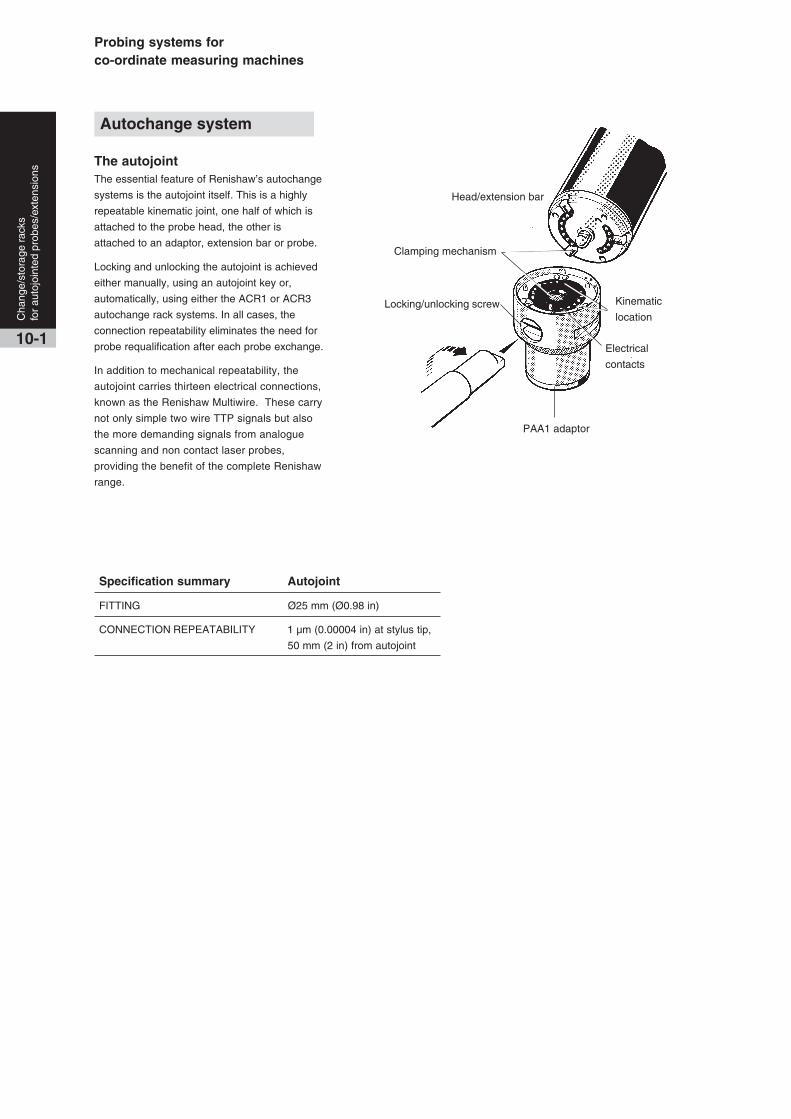
Probing systems forco-ordinate measuring machines
PAA1 adaptor
Head/extension bar
Kinematic
location
Electrical
contacts
Locking/unlocking screw
Clamping mechanism
10-1
Cha
nge/
stor
age
rack
sfo
r au
tojo
inte
d pr
obes
/ext
ensi
ons
Autochange system
The autojointThe essential feature of Renishaw’s autochange
systems is the autojoint itself. This is a highly
repeatable kinematic joint, one half of which is
attached to the probe head, the other is
attached to an adaptor, extension bar or probe.
Locking and unlocking the autojoint is achieved
either manually, using an autojoint key or,
automatically, using either the ACR1 or ACR3
autochange rack systems. In all cases, the
connection repeatability eliminates the need for
probe requalification after each probe exchange.
In addition to mechanical repeatability, the
autojoint carries thirteen electrical connections,
known as the Renishaw Multiwire. These carry
not only simple two wire TTP signals but also
the more demanding signals from analogue
scanning and non contact laser probes,
providing the benefit of the complete Renishaw
range.
Specification summary Autojoint
FITTING Ø25 mm (Ø0.98 in)
CONNECTION REPEATABILITY 1 µm (0.00004 in) at stylus tip,
50 mm (2 in) from autojoint

Cha
nge/
stor
age
rack
sfo
r au
tojo
inte
d pr
obes
/ext
ensi
ons
10-2
Specification summary ACC2-2
DATA TRANSMISSION Serial RS232
USER DEFINABLE Serial Baud Rate 300 - 19200
PARAMETERS Parallel address, parallel poll bit
VOLTAGE RANGE 85-264 V 50/60 Hz
DIMENSIONS HEIGHT 88 mm (3.43 in) 2 ‘U’
WIDTH 289.3 mm (11.4 in) 2/3 of a 19 in rack
DEPTH 220 mm (8.58 in)
WEIGHT 3.85 kg (136 oz)
460 mm (18.1 in)
Leg
204
mm
(7.8
8 in
)
81 mm
(3.2 in)
Leg
104
mm
(3.9
4 in
)
ACR1 autochange rackwith adjustable base
ACR1 autochange rack
ACC2-2 autochange controller for ACR1
The ACR1 system is a fully integrated
8-port probe autochange system. It is
mounted within the machine’s working
envelope and allows probe/stylus
combinations to be exchanged
automatically from heads and extension
bars, without the need for re-qualification.
ACR1 has been revised to allow on-site
configuration of the ports to accommodate
extra large probes such as optical sensors.
It is also possible to use the ACR3 to
autochange between the head and probe
(please see page 10-3).
For further assistance in choosing your
system, please see H-1000-3032/
H-1000-3033 autochange systems
brochure.
Note:
This system can be mounted both
horizontally (as shown) or vertically.
The example shows the flexibility which
substantially increases the usefulness and
effectiveness of the CMM.
Legs are constructed from 104 mm and
204 mm (4.09 in and 8.03 in) modules.
329
mm
(12
.95
in)
with
204
mm
(7.
88 in
) le
g
433
mm
(17
.04
in)
with
308
mm
(11
.81
in)
leg
ACR1 key benefits:
• on-site port configuration facility
• horizontal and vertical mounting
• removal of probes from extension bars
• crash protection system
The ACC2-2 is the RS232 only version of the ACR1 autochange controller.
For IEEE support please contact Renishaw.
Specification summary ACR1
NUMBER OF PORTS 8
DIMENSIONS 460 x 100 x 81 mm
without legs (18.1 x 3.9 x 3.2 in)

Probing systems forco-ordinate measuring machines
10-3
Cha
nge/
stor
age
rack
sfo
r au
tojo
inte
d pr
obes
/ext
ensi
ons
Renishaw’s ACR3 autochange rack is a passive,
4-port probe changing system. It is fitted to
Renishaw’s modular rack system (MRS) which
has been designed to provide a platform for
Renishaw’s latest range of stylus and probe
changing racks.
The ACR3 uses the motion of the CMM to lock/
unlock the autojoint between the probe head and
the probe/extension. ACR3 is therefore a
passive mechanical design without the need for
rack motors or electrical interfacing.
Integration with the metrology software is
required (please consult your machine supplier
for details).
All Renishaw probes and extension bars fitted
with the autojoint can be carried. Some third
party probes that incorporate the Renishaw
autojoint can also be used with ACR3. (Please
consult your machine supplier for details).
For additional flexibility, two four port units can
be linked to provide an eight port system.
The total swept volume along the MRS during a
change cycle is:
1 x ACR3 275 mm (10.27 in)
2 x ACR3s linked 460 mm (18.33 in)
The extruded rail of the MRS is available in
different lengths 400/600/1000 mm (15.8/23.6/
39.4 in) to suit the number and combination of
changer requirements. In addition the height of
the MRS can easily be upgraded after
installation allowing further flexibility to meet
application needs. For more details on the MRS
please refer to section 13-1. Additionally an
ACR3 data sheet H-1000-2024, and autochange
systems brochure H-1000-3032/H-1000-3033
are available.
ACR3 autochange rack
ACR3 features and benefits:
• 4 ports
• rapid exchange between autojointed
products
• can be configured to provide 8 ports
• simple installation/operation
ACR3 and two SCP600’smounted to MRS
35(1.38)
70 (2.76)
105 (4.13)
89 (3.50)
124 (4.88)159 (6.26)
194 (7.90)
dimensionsmm (in)
275 (10.27) swept volume
Unlocked position
Locked position
4-port ACR3 operating envelope
ACR3 4-port systemmounted to MRS
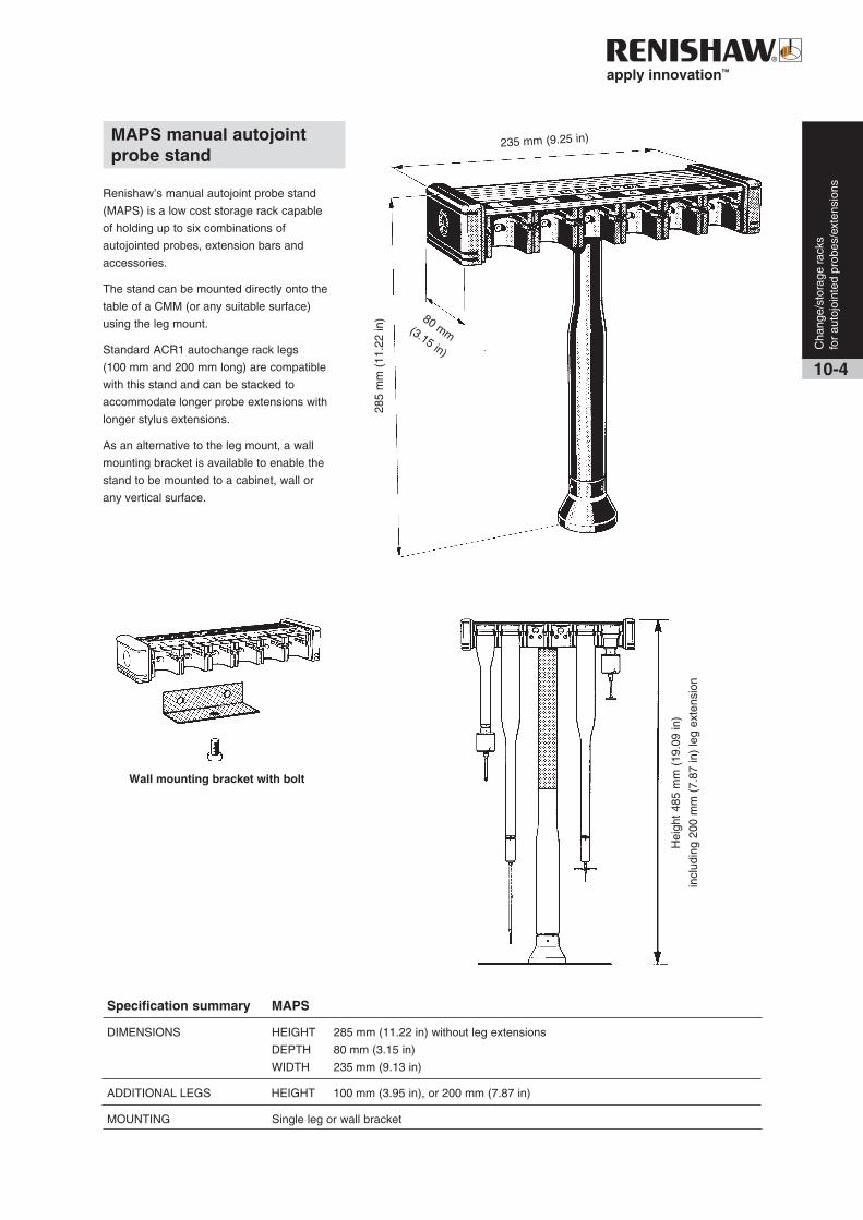
Cha
nge/
stor
age
rack
sfo
r au
tojo
inte
d pr
obes
/ext
ensi
ons
10-4
Renishaw’s manual autojoint probe stand
(MAPS) is a low cost storage rack capable
of holding up to six combinations of
autojointed probes, extension bars and
accessories.
The stand can be mounted directly onto the
table of a CMM (or any suitable surface)
using the leg mount.
Standard ACR1 autochange rack legs
(100 mm and 200 mm long) are compatible
with this stand and can be stacked to
accommodate longer probe extensions with
longer stylus extensions.
As an alternative to the leg mount, a wall
mounting bracket is available to enable the
stand to be mounted to a cabinet, wall or
any vertical surface.
Hei
ght 4
85 m
m (
19.0
9 in
)
incl
udin
g 20
0 m
m (
7.87
in)
leg
exte
nsio
n
80 mm(3.15 in)
235 mm (9.25 in)
285
mm
(11
.22
in)
Wall mounting bracket with bolt
MAPS manual autojointprobe stand
Specification summary MAPS
DIMENSIONS HEIGHT 285 mm (11.22 in) without leg extensions
DEPTH 80 mm (3.15 in)
WIDTH 235 mm (9.13 in)
ADDITIONAL LEGS HEIGHT 100 mm (3.95 in), or 200 mm (7.87 in)
MOUNTING Single leg or wall bracket
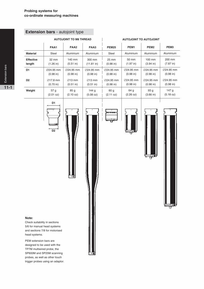
Probing systems forco-ordinate measuring machines
Note:Check suitability in sections
5/6 for manual head systems
and sections 7/8 for motorised
head systems.
PEM extension bars are
designed to be used with the
TP7M multiwired probe, the
SP600M and SP25M scanning
probes, as well as other touch
trigger probes using an adaptor.
PEM2
Aluminium
100 mm
(3.94 in)
∅24.95 mm
(0.98 in)
∅24.95 mm
(0.98 in)
93 g
(3.66 in)
PEM1
Aluminium
50 mm
(1.97 in)
∅24.95 mm
(0.98 in)
∅24.95 mm
(0.98 in)
64 g
(2.26 oz)
PEM3
Aluminium
200 mm
(7.87 in)
∅24.95 mm
(0.98 in)
∅24.95 mm
(0.98 in)
147 g
(5.18 oz)
PAA2
Aluminium
140 mm
(5.51 in)
∅24.95 mm
(0.98 in)
∅13 mm
(0.51 in)
85 g
(2.10 oz)
Extension bars - autojoint type
PAA1
Steel
32 mm
(1.26 in)
∅24.95 mm
(0.98 in)
∅17.8 mm
(0.70 in)
57 g
(2.01 oz)
PAA3
Aluminium
300 mm
(11.81 in)
∅24.95 mm
(0.98 in)
∅13 mm
(0.51 in)
144 g
(5.08 oz)
AUTOJOINT TO M8 THREAD AUTOJOINT TO AUTOJOINT
PEM25
Steel
25 mm
(0.98 in)
∅24.95 mm
(0.98 in)
∅24.95 mm
(0.98 in)
60 g
(2.11 oz)
Material
Effective
length
D1
D2
Weight
D1
D2
11-1
Ext
ensi
on b
ars
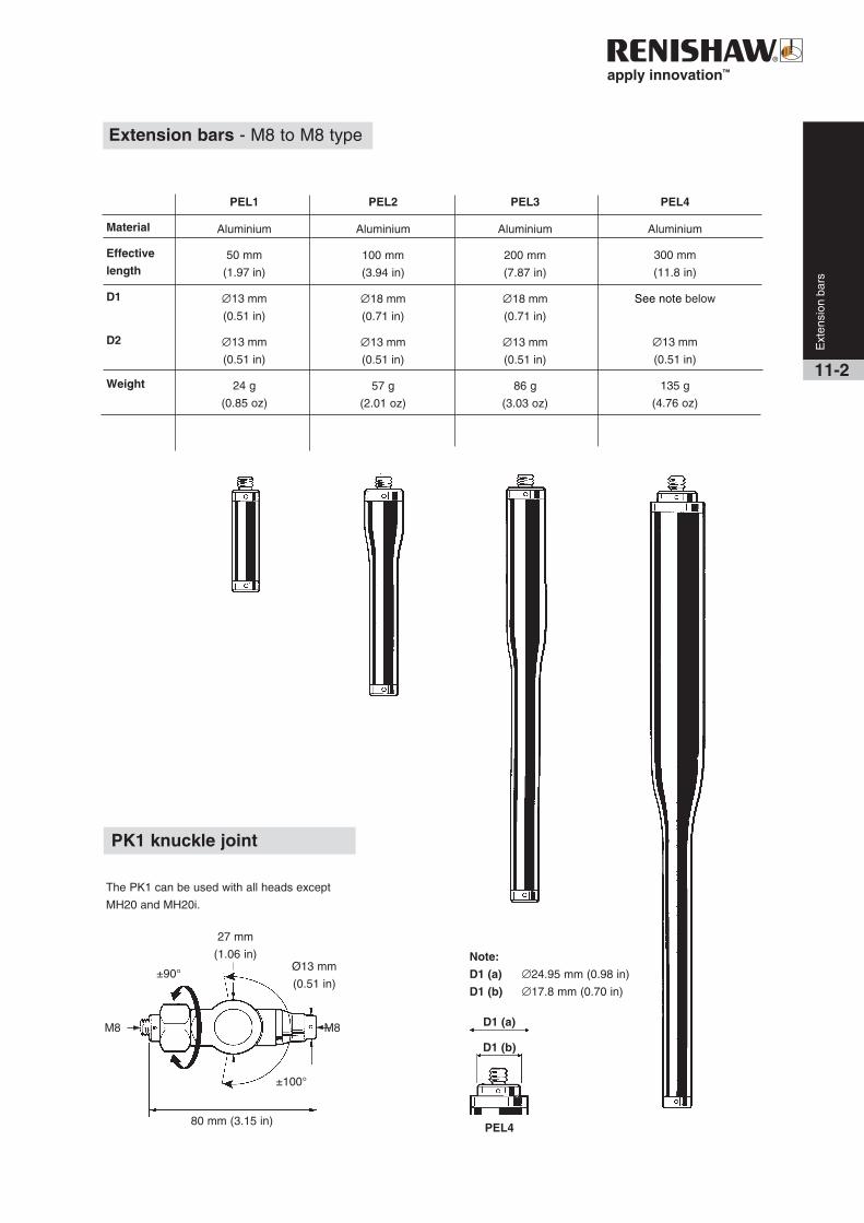
11-2
PEL3
Aluminium
200 mm
(7.87 in)
∅18 mm
(0.71 in)
∅13 mm
(0.51 in)
86 g
(3.03 oz)
PEL4
Aluminium
300 mm
(11.8 in)
See note below
∅13 mm
(0.51 in)
135 g
(4.76 oz)
PK1 knuckle joint
The PK1 can be used with all heads except
MH20 and MH20i.
PEL1
Aluminium
50 mm
(1.97 in)
∅13 mm
(0.51 in)
∅13 mm
(0.51 in)
24 g
(0.85 oz)
PEL2
Aluminium
100 mm
(3.94 in)
∅18 mm
(0.71 in)
∅13 mm
(0.51 in)
57 g
(2.01 oz)
Ø13 mm
(0.51 in)
M8 M8
±90°
80 mm (3.15 in)
27 mm
(1.06 in)
±100°
Ext
ensi
on b
ars
Extension bars - M8 to M8 type
Material
Effective
length
D1
D2
Weight
Note:
D1 (a) ∅24.95 mm (0.98 in)
D1 (b) ∅17.8 mm (0.70 in)
D1 (a)
D1 (b)
PEL4

Probing systems forco-ordinate measuring machines
Shanks are used to mount the probe head to the quill of the machine.
The shanks detailed below are suitable for all Renishaw manual and motorised probe heads (except PH6 and MH20),
as well as the TP1 probe. The correct shank must be chosen to suit the mounting facility of your CMM.
Standard base diameter is 41.35 mm - 41.45 mm (1.62 in - 1.63 in).
MS9 MS10 MS11 MS12
MS5 MS6 MS7 MS8
MS13 MS14 MS15 MS17
MS1 MS2 MS3 MS4
M5 x 0.8 mm
Ø7.0 mm (0.276 in)
Ø20 mm (0.787 in)
1/4 in BSF x 26TPI
1/4in BSF x 26TPI
CirclipWasher
Bush
Ø7.0 mm (0.276 in)Ø7.0 mm (0.276 in)
Ø18.0 mm (0.709 in)
Ø7.0 mm (0.276 in)
Ø10.0 mm(0.394 in)
Ø26 mm (1.02 in)
M10 x 1.5 mm
Ø7.0 mm (0.276 in)
Ø13.965 mm (0.550 in)
Ø16 mm (0.63 in)
Ø7.0 mm (0.276 in) Ø7.0 mm (0.276 in)
Ø 5.0 mm(0.196 in)
85 m
m
(33.
5 in
)
50 m
m
(1.9
7 in
)
60 m
m
(2.3
6 in
)
50 m
m
(1.9
7 in
)
Ø19.991 -20.000 mm
(0.7870 -0.7874 in)
Ø11.989 -12.000 mm
(0.4720 -0.4724 in)
Ø13.997 -14.003 mm
(0.5511 -0.5513 in)
Ø11.993 -11.998 mm
(0.472 -0.477 in)
15.0 mm(0.59 in)
Ø13.960 -13.970 mm(0.5496 -0.5500 in)
Ø14.996 -14.998 mm
(0.5904 -0.5905 in)
Ø13.990 -13.996 mm
(0.5508 -0.5510 in)
Ø24.995 -25.000 mm
(0.9841 -0.9843 in)
Ø15.983 -15.994 mm
(0.6293 -0.6297 in)
Ø13.997 -14.003 mm
(0.5511 -0.5513 in)
Ø10.008 -10.013 mm(0.3940 -0.3942 in)
Ø9.500 -9.512 mm
(0.3740 -0.4745 in)
Ø9.497 -9.524 mm
(0.3739 -0.3750 in)
Ø24.989 -24.984 mm
(0.9838 -0.9840 in)
Ø10.008 -10.013 mm
(0.3940 -0.3942 in)
43.9
mm
(1.7
3 in
)
25.4
mm
(1.0
0 in
)
50.8
mm
(2.0
in)
36.6
8 m
m(1
.44
in)
45.4
7 m
m
(1.7
9 in
)
40 m
m
(1.5
7 in
)
35 m
m
(1.3
87 in
)
85 m
m
(33.
5 in
)66
mm
(2.6
0 in
)
26 m
m
(1.0
2 in
)
19 m
m
(0.7
5 in
)
25 m
m
(0.9
8 in
)
13 mm (0.512 in)
47 m
m(1
.85
in)
Ø16
mm
(0.6
30 in
)
12-1
Sha
nks
Shanks (except PH6 and MH20)
11 mm (0.43 in)
63 m
m
(2.4
8 in
)
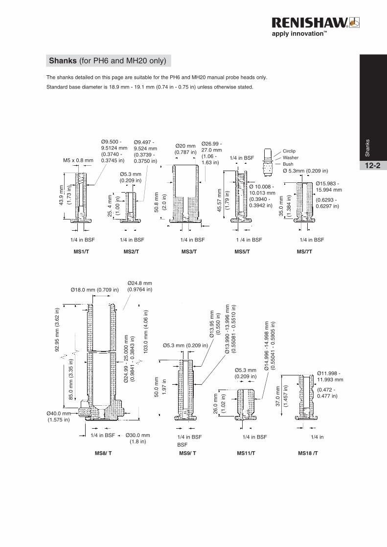
The shanks detailed on this page are suitable for the PH6 and MH20 manual probe heads only.
Standard base diameter is 18.9 mm - 19.1 mm (0.74 in - 0.75 in) unless otherwise stated.
MS1/T MS2/T MS3/T MS5/T MS/7T
MS8/ T MS9/ T MS11/T MS18 /T
1/4 in BSF 1/4 in BSF 1/4 in BSF 1 /4 in BSF 1/4 in BSF
1/4 in BSF
CirclipWasherBush
43.9
mm
(1.7
3 in
)
25. 4
mm
(1.0
0 in
)
45.5
7 m
m
(1.7
9 in
)
50.8
mm
(2.0
in)
35.0
mm
(1.3
84 in
)
Ø 5.3mm (0.209 in)
Ø15.983 -15.994 mm
(0.6293 -0.6297 in)
Ø 10.008 -10.013 mm(0.3940 -0.3942 in)
1/4 in BSF
Ø20 mm(0.787 in)
Ø26.99 -27.0 mm(1.06 -1.63 in)
Ø5.3 mm(0.209 in)
M5 x 0.8 mm
Ø18.0 mm (0.709 in)
Ø5.3 mm (0.209 in)
Ø5.3 mm(0.209 in)
103.
0 m
m (
4.06
in)
50.0
mm
1.97
in
26.0
mm
(1.0
2 in
)
37.0
mm
(1.4
57 in
)
Ø11.998 -11.993 mm
(0.472 -0.477 in)
Ø13
.95
mm
(0.5
50 in
)
Ø24.8 mm(0.9764 in)
Ø40.0 mm(1.575 in)
92.9
5 m
m (
3.62
in)
85.0
mm
(3.
35 in
)
Ø24
.99
- 25
.000
mm
(0.9
841
- 0.
3843
in)
Ø13
.990
-13
.996
mm
(0.5
5081
- 0
.551
0 in
)
Ø14
.996
-14
.998
mm
(0.5
5041
- 0
.590
5 in
)
Ø30.0 mm(1.8 in)
1/4 in BSF 1/4 in BSF 1/4 in
BSF
Sha
nks
12-2
Shanks (for PH6 and MH20 only)
Ø9.500 -9.5124 mm(0.3740 -0.3745 in)
Ø9.497 -9.524 mm(0.3739 -0.3750 in)

Probing systems forco-ordinate measuring machines

Renishaw’s modular rack system (MRS)
allows customisation of probe and stylus
changing racks to optimise CMM
functionality.
The MRS is a modular system designed to
provide a platform for Renishaw probe and
stylus changing racks. It comprises a rail and
two leg assemblies, and is available in three
different standard rail lengths, 400 mm, 600
mm and 1000 mm (15.7 in, 23.6 in and 39.4
in) to suit a number of changer requirements.
The MRS rail can also be placed at different
heights from the CMM’s bed by using
multiple MRS legs to allow the required
clearance for long styli and extension bars.
The standard interconnecting MRS legs
supplied (4 per kit) are each 125 mm
(4.92 in) long. A maximum recommended leg
length of 500 mm (19.68 in) can be achieved
by purchasing additional legs. These are
available in either 62.5 mm or 125 mm
(2.46 in or 4.92 in) lengths. The rack is
mounted on the CMM bed via two MRS feet
attached to the legs.
Where heavier rack system configurations
are to be used e.g. multiple SCP80s
mounted to a 1000 mm (39.37 in) rail length,
the MRS system can be upgraded by using
the optional heavy duty legs which are
Ø60 mm x 350 mm long (Ø2.36 in x 13.78 in
long). These legs mount beneath the
standard legs/feet and are attached to the
CMM bed.
The MRS is compatible with the following
Renishaw change rack systems:
• FCR25 (flexible change rack for
SP25M)
• SCP80 (stylus change port for SP80)
• SCP600 (stylus change port for
SP600/SP600M/SP600Q)
• ACR3 (autochange rack)
MRS modular rack system
13-1
Acc
esso
ries
MRS with SCP600
SCP600
M8 screw
Step back adaptor
Leg
Rail
Grubscrew
Foot
Foot/leg adaptor
MRS components

Probing systems forco-ordinate measuring machines
Acc
esso
ries
13-2
MRS heavy duty legs
Where an MRS installation has numerous
SCP80s containing heavy stylus
arrangements, or vertical stylus
arrangements exceeding 190 mm, it is
recommended that the optional MRS heavy
duty leg kits are used to provide additional
rigidity/height.
These kits are purchased separately to match
the number of legs used in the MRS
installation. The heavy duty leg kit stands
330 mm (13 in) tall and is positioned between
the CMM table and the standard MRS leg
assembly.
Note: The MRS heavy-duty leg kit part
number is A-4192-0020 and comprises one
heavy duty leg assembly. Therefore, two kits
are required for a typical MRS installation.
MRS heavy duty leg kit
1. Heavy duty leg
2. Double-ended threaded stud *
3. Footplate
Standard MRS kit parts
4. Standard MRS leg
5. Leg to foot adaptor
6. M10 bolt
7. MRS foot
8. MRS rail
9. Step back adaptor
10. Tee nut and bolt
MRS adjustable footplates
By using the optional MRS adjustable
footplates, the MRS rail can also be
placed at different positions on the
CMM’s table thereby ensuring that a
maximised working volume can be
achieved. The MRS adjustable
footplates can be used with the MRS
standard leg and the MRS heavy duty
leg arrangements. The range of
adjustment is via four boltholes in steps:
25/50/75/100 mm (0.98/1.97/2.95/
3.94 in).
Note: The MRS adjustable footplates kit
part number is A-4192-0702 and
comprises two footplates.
MRS
heavy duty
leg
assembly
MRS
standard
leg
assembly
MRS adjustable
footplate
MRS adjustable footplate arrangements with standard and heavy
duty MRS leg arrangements
MRS adjustable
footplate
* Two sets of double ended threaded studs are provided to suit different
CMM table configurations. The thread sizes supplied are M10, M8 and M6.
Alternatively, 3/16 “ UNC and 5/16 “ UNC can be provided on request to
your Renishaw supplier.
MRS heavy duty leg kit
Ø60 mm
(Ø2.68 in)
15 m
m
(0.5
9 in
)31
5 m
m (
12.4
in)
1
2
3
4
5
6
7
1
Connecting the standard leg
to the heavy duty leg
4
9
8
10
Step back adaptor
arrangement

13-3
Acc
esso
ries
Detail showing alternative legarrangement using step back adaptor
SCP80 SCP600 FCR25 ACR3
Dockingaxis
H2
H1
Specification summary MRS Kit 1 MRS Kit 2 MRS Kit 3
RAIL LENGTH 400 mm (15.75 in) 600 mm (23.62 in) 1000 mm (39.40 in)
Note: allow additional 10 mm (0.40 in) for plastic end caps
NUMBER OF LEGS REQUIRED (RECOMMENDED) 2 2 ‡ 2 ‡
MAXIMUM USEABLE RAIL LENGTH
With two legs mounted to underside of rail (as shown) 320 mm (12.60 in) 520 mm (20.47 in) 920 mm (36.22 in)
With legs mounted via step back adaptor (see detail) 400 mm (15.75 in) 600 mm (23.62 in) 1000 mm (39.40 in)
HEIGHT TO TOP OF RAIL (using legs supplied with MRS kit)
With two legs mounted to underside of rail (as shown) 325 mm (12.8 in) 325 mm (12.8 in) 325 mm (12.8 in)
With legs mounted via step back adaptor (see detail) 317 mm (12.5 in) 317 mm (12.5 in) 317 mm (12.5 in)
HEIGHT OF ADDITIONAL SINGLE LEG 62.5 mm (2.46 in) 62.5 mm (2.46 in) 62.5 mm (2.46 in)
125 mm (4.92 in) 125 mm (4.92 in) 125 mm (4.92 in)
HEIGHT OF ADDITIONAL HEAVY DUTY SINGLE LEG 330 mm (12.99 in) 330 mm (12.99 in) 330 mm (12.99 in)
Ø60 mm (2.36 in)
HEIGHT OF ADDITIONAL ADJUSTABLE FOOTPLATE 16 mm (0.630 in) 16 mm (0.630 in) 16 mm (0.630 in)
DISTANCE FROM PORT CENTRE TO LEG CENTRE (in docking axis)
D1 = with legs mounted to FCR25 41 mm (1.61 in) 41 mm (1.61 in) 41 mm (1.61 in)
underside of rail (as shown) ACR3 56 mm (2.20 in) 56 mm (2.20 in) 56 mm (2.20 in)
SCP600 69.2 mm (2.72 in) 69.2 mm (2.72 in) 69.2 mm (2.72 in)
SCP80 134 mm (5.27 in) 134 mm (5.27 in) 134 mm (5.27 in)
D2 = with legs mounted via FCR25 94 mm (3.70 in) 94 mm (3.70 in) 94 mm (3.70 in)
step back adaptor (see detail) ACR3 109 mm (4.29 in) 109 mm (4.29 in) 109 mm (4.29 in)
SCP600 122.2 mm (4.81 in) 122.2 mm (4.81 in) 122.2 mm (4.81 in)
SCP80 187 mm (7.36 in) 187 mm (7.36 in) 187 mm (7.36 in)
RAIL LENGTH REQUIRED PER FCR25 115.8 mm (4.56 in) 115.8 mm (4.56 in) 115.8 mm (4.56 in)
CHANGER UNIT ACR3 280 mm (11.02 in) 280 mm (11.02 in) 280 mm (11.02 in)
SCP600 87 mm (3.42 in) 87 mm (3.42 in) 87 mm (3.42 in)
SCP80 133 mm (5.24 in) 133 mm (5.24 in) 133 mm (5.24 in)
✱ includes 2 mm (0.08 in) extra allowance per unit ✱✱ includes 5 mm (0.20 in) extra allowance per unit
‡ centre leg may be required in certain applications
✱
✱✱
✱
✱
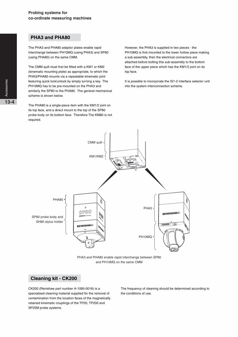
Probing systems forco-ordinate measuring machines
Acc
esso
ries
13-4
CK200 (Renishaw part number A-1085-0016) is a
specialised cleaning material supplied for the removal of
contamination from the location faces of the magnetically
retained kinematic couplings of the TP20, TP200 and
SP25M probe systems.
Cleaning kit - CK200
The frequency of cleaning should be determined according to
the conditions of use.
PHA3 and PHA80
The PHA3 and PHA80 adaptor plates enable rapid
interchange between PH10MQ (using PHA3) and SP80
(using PHA80) on the same CMM.
The CMM quill must first be fitted with a KM1 or KM2
(kinematic mounting plate) as appropriate, to which the
PHA3/PHA80 mounts via a repeatable kinematic joint
featuring quick lock/unlock by simply turning a key. The
PH10MQ has to be pre-mounted on the PHA3 and
similarly the SP80 to the PHA80. The general mechanical
scheme is shown below.
The PHA80 is a single-piece item with the KM1/2 joint on
its top face, and a direct mount to the top of the SP80
probe body on its bottom face. Therefore The KM80 is not
required.
However, the PHA3 is supplied in two pieces - the
PH10MQ is first mounted to the lower hollow piece making
a sub-assembly, then the electrical connectors are
attached before bolting this sub-assembly to the bottom
face of the upper piece which has the KM1/2 joint on its
top face.
It is possible to incorporate the IS1-2 interface selector unit
into the system interconnection scheme.
CMM quill
KM1/KM2
SP80 probe body and
SH80 stylus holder
PHA80
PH10MQ
PHA3
PHA3 and PHA80 enable rapid interchange between SP80
and PH10MQ on the same CMM

13-5
Acc
esso
ries
The Renishaw universal datum sphere complements the
performance of manual and fully automated CMMs.
Quick and easy adjustment to set ball stem over a wide
range of probe qualification angles. This enables qualification
above, centrally and below the ball. The hand adjustable
pivot joint enables stem rotation through 360° in the
horizontal plane, and ±45° in the vertical plane.
Each datum sphere is supplied with its own certificate, giving
ball diameter and roundness. All sphere measurements are
performed on equipment traceable to UK (NPL) standards.
A vertical positioning feature provides positive feel when the
stem arrives in the vertical position.
Vertical height from the table to centre of all ball sizes is
approximately 173 mm (6.82 in). An optional pillar extension
increases height to 248 mm (9.76 in).
Pivotcentre
Pivot
centre
45° 45°
154 mm(6.06 in)nominal
229 mm(9.02 in)nominal
190 mm(7.48 in)nominal
245 mm(9.66 in)nominal
170 mm(6.71 in)nominal
115 mm(4.52 in)nominal
55 mm(2.18 in)
UDS universal datum sphere
Universal datum sphere kit comprising:
• One datum ball (selected by size):
Ø12 mm, Ø19 mm, Ø25 mm, Ø3/4 in or Ø1 in.
• Pivot pillar, base, ‘C’ spanner
• Ball certificate and storage box
• Adaptor available for twin ball applications (optional)
Fixing stud
A fixing stud is required with each kit to attach the pillar
to the table surface. Fixing stud thread sizes are:
M6 x 1, M8 x 1.25, M10 x 1.5, 5/16 in UNC, 3/8 in UNC
Optional extras
Datum ball Ø12 mm, Ø19 mm, Ø25 mm,
Ø3/4 in, Ø1 in.
Adaptor 2 way adaptor, 3 way adaptor
Pillar extension 75 mm (2.96 in) long
Features• Hard wearing tungsten carbide sphere (ball) available
in five sizes: Metric Ø12, Ø19 and Ø25 mm
Imperial Ø3/4 and Ø1 in
• Sphericity to within 0.1 µm (0.000004 in)
• Diametric tolerance ±1 µm (±0.00004 in)
Standard arrangement
Using optional pillar extension

Probing systems forco-ordinate measuring machines
Acc
esso
ries
13-6
Special calibrated stylus can be used with TP1,
TP2, TP20, TP6, TP6A, MIP* and PH50* with
suitable adaptors.
* Obsolete products
Mahogany storage box
Additional w
eight
1.5 mm A/F hexagonal key
Calibration traceable to USA National Institute of
Standards and Technology (Ref #731/23897-87).
The machine checking gauge also complies with
British Standard BS EN ISO 10360-2.
The probe’s stylus slots into the end of what is in
effect a reference ballbar. The probe carries the bar
with it over a circular path, and radial readings are
taken at 0°, +45° and -45° elevations. The range of
these readings indicates the volumetric measuring
performance of the CMM. Repetition of a sequence
of readings checks the system for repeatability.
Volumetric measuring performance is the maximum
error between any two points in any plane, over any
distance within the full measuring volume.
Notes:
✿ These items are included in the MCG2 kit
✱ Maximum negative arm angle possible is 42°
when using MCG1 kit with the longest arm
320 mm (12.60 in) and both pillars supplied,
127 mm + 76 mm = 203 mm (5 in + 3 in = 8 in)
}
Specification
CHECKING TIME
CNC (DCC) machine Typically 15 minutes
Joystick machine
Manual machine
MEASURING RANGE
Vertically ±45° ✱
Horizontally 360°
TOTAL GAUGE ERROR ±0.5 µm (±0.00002 in)
Kit Description
MCG1 Small kit
machines up to 1 m3 (35.315 ft3)
MCG2 Comprehensive kit
machines greater than 1 m3 (35.315 ft3) Typically 45 minutes
R = Radius from calibrated pivot to stylus ball centre
Baseplate
R=226 mm (9
in)R=532 mm (2
1 in)
R=685 mm (2
7 in)
R=151 mm (6
in)
Calibratedpivot
Arms
R=101 mm (4
in)
76 mm (3 in)
127 mm (5 in)
235 mm (9.25 in)
R=380 mm (1
5 in)
+ 45°
0° R
- 45°
✿
✿
MCG machine checking gauge
✿

13-7
Acc
esso
ries
Renishaw’s gram gauge enables the adjustment,
reset and checking of probe trigger force
settings on all standard Renishaw CMM touch
trigger probes. Setting the optimum trigger force
using the gram gauge maximises a probe’s
performance.
The gram gauge can be used to set trigger
force settings over a range from 4 to 35 grams.
The scale graduations are set at 1 gram
intervals which is sufficient for all probe trigger
force measurements on CMMs.
Due to the use of SI units, the trigger force for
probes is given in Newtons. The conversion
factor used is 1 gf = 0.01 N.
Specification
OVERALL LENGTH 95 mm (3.74 in)
NEEDLE LENGTH 41 mm (1.61 in)
DEPTH 27 mm (1.06 in)
WIDTH 43 mm (1.69 in)
RANGE 4 to 35 gram range with
1 gram graduations
Gram gauge
* This is the optimum trigger force recommended by Renishaw.
Higher trigger forces may be required for longer styli.
MSR1 manual storage rackfor manual or DCC CMM operation
The MSR1 holds up to six pre-qualified stylus
assemblies for fitting to TP20 or TP200 probe
modules. It eases the operators’ task where
manual module changing is performed and
thus aids productivity improvements.
The MSR1 can be table mounted (as shown) or
wall mounted using a bracket. The rack is
intended for use on either manual or DCC
CMMs, to hold pre-qualified stylus assemblies
fitted to TP20 or TP200 probe modules. It
provides convenient storage and protects the
kinematic coupling mechanism from
contamination.
MSR1 manual storage rack
Probe type Stylus length Optimum trigger force
TP1 31 mm (1.22 in) 0.15 N (0.52 ozf)
TP2-5W 10 mm (0.39 in) 0.07 N to 0.08 N (0.24-0.28 ozf)
TP6 21 mm (0.82 in) 0.11 N to 0.13 N (0.38-0.45 ozf)
TP6A 21 mm (0.82 in) 0.11 N to 0.13 N (0.38-0.45 ozf)
MIP 21 mm (0.82 in) 0.11 N to 0.13 N (0.38-0.45 ozf)
*
Specification (table mount version)
OVERALL HEIGHT 285 mm (11.2 in)
DEPTH (inc wall bracket) 86 mm (3.4 in)
WIDTH 236 mm (9.3 in)

Probing systems forco-ordinate measuring machines
Comprehensive information on Renishaw’sstyli products can be found in the styli andtechnical specifications document(H-1000-3200).
Accuracy at the point of contact
As industry has developed its requirement for
increasingly diverse and complex
manufactured parts, inspection systems have
had to work hard to keep up. The use of
CMMs with probing systems, and in-process
inspection on machine tools, are two of the
solutions offered by Renishaw to help you
maximise your productivity and maintain the
highest possible standards of quality.
Successful gauging depends very much on
the ability of the probe’s stylus to access a
feature and then maintain accuracy at the
point of contact. Renishaw has used its
expertise in probe and stylus design to
develop a comprehensive range of CMM and
machine tool styli to offer the greatest
possible precision.
These notes explain the critical features of each
stylus type, helping you to choose the right
design for each inspection need.
What is a stylus?
A stylus is that part of the measuring system
which makes contact with the component,
causing the probe mechanism to displace, the
generated signal enabling measurement to be
taken. The feature to be inspected dictates the
type and the size of stylus used. However, in
all cases maximum rigidity of the stylus and
perfect sphericity of the tip are vital.
The performance of gauging can easily
be degraded if a stylus is used with poor
ball roundness, poor ball location, bad thread
fit or a compromised design that allows
excessive bending during measurement.
To ensure the integrity of the data gathered,
make certain that a stylus from the
comprehensive range of genuine Renishaw styli
is specified and used.
Choosing a stylus
To maintain accuracy at the point of contact it is
recommend that:-
• Styli be kept short
• Joints minimise
• A large as possible styli ball is used
Styli
14-1
Sty
li an
d cu
stom
des
ign
serv
ice

14-2
Sty
li an
d cu
stom
des
ign
serv
ice
Ruby
Silicon nitride
Zirconia
Genuine Renishaw styli ball materials
Ruby
The industry standard and the optimum stylus ball material for a
vast majority of measurement applications is ruby, one of the
hardest known materials.
Very few applications exist where ruby is not the best ball
material. However, there are two such applications where balls
manufactured from other materials are recommended, and
these are Silicon nitride and Zirconia.
Silicon nitride
For heavy duty scanning applications on aluminium, a
phenomenon known as ‘adhesive wear’ can occur, which
involves build up of aluminium from the surface onto the ball.
The preferred ball material for this application is Silicon nitride.
Silicon nitride possesses many similar properties to ruby. It is a
very hard and wear resistant ceramic which can be machined
into very high precision spheres. It can also be polished to an
extremely smooth surface finish. Silicon nitride does not have
the attraction to aluminium and so does not exhibit the adhesive
wear seen with ruby in similar applications. Silicon nitride does,
however, show significant abrasive wear characteristics when
scanning steel surfaces so its applications are best confined to
aluminium.
Zirconia
In heavy duty scanning applications on cast iron. Interaction
between the two materials can result in ‘abrasive wear’ of the
ruby ball’s surface. For such applications, Zirconia balls are
recommended.
Zirconia is a particularly tough ceramic material with hardness
and wear characteristics approaching those of ruby. Its surface
properties, however, make it an ideal material for aggressive
scanning applications on cast iron components.
Stylus types
The genuine Renishaw stylus range comprises several types:
Straight styli Cylinder styli
Star styli Pointer styli
Disc styli Ceramic hollow ball styli
Accessories and tools
Stylus centres Stylus thread adaptors
Stylus knuckles Stylus tools
Stylus extensions Stylus cranks
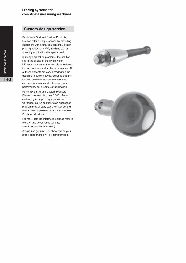
Probing systems forco-ordinate measuring machines
14-3
Renishaw’s Styli and Custom Products
Division offer a unique service by providing
customers with a total solution should their
probing needs for CMM, machine tool or
scanning applications be specialised.
In many application problems, the solution
lies in the choice of the stylus which
influences access of the workpiece features,
inspection times and probe performance. All
of these aspects are considered within the
design of a custom stylus, ensuring that the
solution provided incorporates the ideal
choice of materials and optimises probe
performance for a particular application.
Renishaw’s Styli and Custom Products
Division has supplied over 5,000 different
custom styli into probing applications
worldwide, so the solution to an application
problem may already exist. For advice and
further details, please contact your nearest
Renishaw distributor.
For more detailed information please refer to
the styli and accessories technical
specifications (H-1000-3200)
Always use genuine Renishaw styli or your
probe performance will be compromised!
Custom design service
Cus
tom
des
ign
serv
ice


Probing systems forco-ordinate measuring machines
Accuracy For touch trigger probes, the accuracy is stated in terms of the uncertainty of
measurement arising from error sources such as repeatability and pretravel variation.
Analogue probe A proportional probe in which the displacement of the stylus is represented by a
continuously variable output voltage or current proportional to the displacement.
Autojoint Renishaw’s patented highly repeatable 2-part coupling, incorporating a 13-pole connector,
which allows probes or extension bars to be interchanged without requalification.
Contact probe A probe that uses a stylus to physically touch the target gauge point on the workpiece
whose co-ordinates are to be recorded.
Controller The electronic unit that controls the motion and positioning of an actuator or motion
system. Examples are the controllers for a probe head or the axes of a CMM.
Datum The reference feature (line or plane) from which other co-ordinates are measured.
E-bar or ebar An abbreviated name for extension bar.
Edge triggering The ability of a non-contact probe to automatically locate the edge or boundary of
contrasting features on the workpiece.
EWL Effective working length.
Extension Device for increasing the reach of a probe or stylus. Extensions placed between the
probe and the probe head are known as ‘extension bars’ or ‘ E-bars’.
Indexing head An articulating probe head that may be oriented and locked in a number of repeatable
kinematically seated spatial positions. After the stylus tips have been qualified at each
required position, the head may be moved to any of these positions without requalification.
Jog An incremental move of an indexing head to an adjacent position.
Kinematic seating A mechanism in which the spatial position of a movable component, when located in the
seated position, is kinematically constrained by 6 contact points formed by a system of
rollers (or ‘V’ grooves) and ball bearings.
Kinematic A contact probe in which the kinematic seating forms an electrical circuit where the
resistance varies as the stylus is displaced in its mounting, to provide the trigger signal.
After displacement, the stylus ball returns to the highly repeatable position defined by the
kinematic location points.
Kinematics The science of motion, independent of force.
Lobing Used to describe the form measurement error of kinematic switching probes resulting
characteristics from the tri-lobed pretravel pattern (in the X-Y plane) that characterises this type of
sensor mechanism. Refer to pretravel variation.
M8 connector The threaded 2-pole connector used to mount a range of probes to the probe head.
Multiwire The method of interconnection from a probe head fitted with a 13-pole autojoint
connector to a probe interface.
Overtravel The distance that the CMM takes to stop following the assertion of a probe trigger signal.
Overtravel force The force applied by the stylus ball to the surface at a defined overtravel displacement.
PICS Acronym for Renishaw’s product interconnection system.
Pretravel The displacement from the point where the stylus ball contacts the workpiece,
to the point where a probe trigger is asserted.
Glossary of terms
15-1
Glo
ssar
y of
term
s

Glo
ssar
y of
term
s
15-2
Pretravel Also called form measurement error or lobing, this source of systematic
variation error is predominant in kinematic switching probes where a tri-lobed
(PTV or XYPTV) pretravel pattern (in the X-Y plane) characterises this type of sensor mechanism.
Probe The sensor that locates the features to be gauged, relative to the CMM scales.
Probe head A device fitted to the quill of the CMM that carries the probe mounting connector.
Probe heads may have fixed orientation or may articulate to provide re-orientation of
the probing axis. Articulating heads may be manually operated or motorised.
Probe interface An electronic unit that processes the output from the probe sensor and communicates
with the CMM controller.
Proportional A displacement measuring probe that provides an output, which may be analogue or
probe digital, proportional to stylus displacement over a defined operating range.
Qualification The procedure in which the measurement processor determines the radius of the
stylus tip and its position relative to the scale reference marks or other datum by
gauging a calibrated reference sphere or ring gauge.
Quill The moving component of the CMM that carries the probe, also called the ram.
Repeatability “The quantitative degree of agreement between results of successive measurements
of the same quantity under identical conditions.”
Unidirectional repeatability is specified for touch trigger probes.
Requalification Repetition of the qualification procedure that may be necessary after changing or
moving components in the measurement path, or following a change to ambient temperature
Retrofit The installation of new products or parts onto equipment that is in service.
Scanning probe A proportional probe that is passed over the surface of the workpiece in a continuous
movement sending data to the processor at a high rate.
Sense directions The directions of gauging relative to the probe’s coordinate system.
Servo A motorised articulating probe head that may be oriented to virtually any desired spatial
positioning head position with fine resolution. The position is held during probing by the servo
control system. High precision rotary position encoders eliminate the need for requalification.
Shank A plain or tapered shaft for mounting a probe or probe head to the quill of the CMM.
Stylus The part of contact probes that makes physical contact with the feature to be gauged.
Stylus changing A system based on a highly repeatable kinematically constrained coupling, to allow the
fast exchange of stylus configurations without requalification.
Swept radius On an articulating probe head, the distance from the centre of rotation of the ‘A’ axis to
the probe or stylus mounting face.
Touch trigger probe A discrete point taking type of contact probe.
Trigger force The force that must be applied at the stylus tip to trigger the probe.
TTP Touch trigger probe/probing
Unidirectional The variation of the position of successive triggers taken in the same direction of
repeatability triggering under constant conditions.

Probing systems forco-ordinate measuring machines
Product Description Page
AC1 / AC2 Interface card for use with SP600/M/Q probes (AC2 has higher resolution) 4-13
AC3 Interface card for use with SP25M probe 4-3
ACC2-2 Controller for ACR1 autochange rack 10-2
ACR1 Autochange rack with 8 ports for changing autojoint mount probes/extensions 10-2(requires ACC2-2 integration)
ACR2 Autochange rack for PHS1 7-4
ACR3 Autochange rack with 4 ports for changing autojoint mount probes/extensions 10-3(requires software integration)
AM1 Adjustment module for alignment of PH10T/M probe heads 8-5
AM2 Adjustment module for alignment of PH10MQ probe head 8-5
FCR25 Change rack unit with 3 ports for changing all SP25M probe elements - mounts to MRS 4-4
FCR25-L3 Change rack with 3 ports for changing all SP25M probe elements 4-4
FCR25-L6 Change rack with 6 ports for changing all SP25M probe elements 4-4
Gram gauge Gram gauge for use when adjusting force on TP2-5W, TP1 (S), 13-7TP6, TP6A touch trigger probes
HA-8 Interchangeable probe arm, with M8 probe mount, for PHS1 probe head 7-1
HA-M Interchangeable probe arm, with autojoint probe mount, for PHS1 probe head 7-1
HCU1 Hand held control unit for use with PHC10-2 (re PH10T/M/MQ probe heads) 9-2
HE330/500/750 Interchangeable probe arm extension (330/500/750 mm lengths), 7-1with M8 probe mount, for PHS1 head
IS1-2 Interface selector for Renishaw and some third party probes 9-3
IU80 Interpolator unit for use with SP80 probe 4-8
KM1 / KM2 Kinematic quill mount plate for PHS1 probe head 7-1
KM80 Kinematic quill mount plate for SP80 probe 4-6
MAPS Manual autojoint probe stand, for storage of autojoint mount probes/extensions 10-4
MCG Machine checking gauge for diagnostic testing of CMM axes alignments 13-6
MCR20 Change rack for TP20 stylus modules 3-5
MCU1 Multi-functional hand control unit for use with UCC1 controller 9-6
MH8 Manual indexing probe head with M8 probe mount - shank mount to CMM 5-5
MH20 Manual articulating probe head with integral mount for TP20 stylus module 6-1– shank mount to CMM
MH20i Manual indexing probe head with integral mount for TP20 stylus module 6-2– shank mount to CMM
MIH / MIH-S Manual indexing probe head with an autojoint (non multi-wire) probe mount 5-4- shank mount to CMM
MRS Modular rack system for carrying FCR25, SCP600, SCP80 and ACR3 changer units 13-1
MS## Shanks - wide selection available (also see page 12-2) 12-1
MSR1 Module storage rack for TP20 and TP200 stylus modules 13-7
PAA1/2/3 Extension bars - ‘autojoint to M8’ type 11-1
PEL1/2/3/4 Extension bars – ‘M8 to M8’ type 11-2
PEM1/2/3/25 Extension bars - ‘autojoint to autojoint’ type 11-1
PHA1/PHA2 Probe head adaptors for rapid interchange between PH10M/T 7-3and PHS on the same CMM
PHA3/PHA80 Probe head adaptors for rapid interchange between PH10MQ and 13.4SP80 on the same CMM
PH1 Manual articulating probe head with M8 probe mount - shank mount to CMM 5-7
PH6 Fixed probe head with M8 probe mount - shank mount to CMM 5-6
16-1
Pro
duct
inde
x
Product index
Introduction
Renishaw’s technology
Renishaw stands at the forefront of
automated metrology, with the Group’s
products providing manufacturers with the
ability to machine components accurately,
and perform measurement traceable to
international standards.
Probe technology, allows fast, highly
repeatable measurements to be carried out
on co-ordinate measuring machines
(CMMs).
A wide range of automated probing
systems has been developed to meet the
needs of post-process inspection, for
quality control.
During the manufacturing operation, probes
used on computer numerically controlled
(CNC) machine tools provide the
measurement capability to automatically
control the machining process. This
eliminates the need for costly, time
consuming manual procedures.
Renishaw gives extra capability to CNC
machine tools and CMMs by enabling
scanning and digitising of 3-dimensional
(3D) forms to generate the necessary NC
programs to produce either replica parts, or
moulds and dies.
Renishaw has developed the Cyclone
scanning machine and associated software,
a cost-effective solution to stand-alone
digitising.
The revolutionary manufacturing system,
RAMTIC (Renishaw’s automated milling,
turning and inspection centre), maximises
the potential of existing machine tools,
enabling milling, turning and inspection on
a single machine, together with automated
loading and unloading of materials and
tools.
CNC machine tools and CMMs benefit from
regular volumetric checking by Renishaw’s
automated ball-bar and machine checking
gauge.
Comprehensive machine calibration can be
undertaken, when necessary, using
Renishaw’s innovative laser calibration
systems.
Renishaw has developed linear scale, laser
interferometer and encoder systems for
fitting to a variety of machines, to provide
axis displacement measurement. Dedicated
lengths of rigid scale are not required, since
Renishaw’s approach has been to produce
flexible scale that can be dispensed from a
reel and cut to the required length.
Renishaw has also applied its innovatory
approach to produce a Raman microscope
and accessories for 2D spectral analysis of
materials in a non-destructive manner.
From its leading market position, the
Renishaw Group continues to expand its
product range into ever increasing business
sectors worldwide. Identifying and targeting
new market opportunities has led to the
continuous development and introduction of
new, highly innovative products which
significantly enhance the manufacturing
capabilities in a wide range of industries.
Pro
duct
inde
x
16-2
Product Description Page
PH6M Fixed probe head with multiwire autojoint probe mount – shank mount to CMM 5-6
PH10M Motorised indexing probe head with multi-wire autojoint probe mount 8-3- shank mount to CMM
PH10MQ Motorised indexing probe head with multi-wire autojoint probe mount 8-3- in-quill mount to CMM
PH10T Motorised indexing probe head with M8 probe mount - shank mount to CMM 8-1
PHC10-2 Controller for PH10T/M/MQ probe heads 9-2
PHS1 Motorised (servo type) probe head – mounts to CMM using KM1 or KM2 7-1
PI 4-2 Interface for standard touch trigger probes (excluding TP7M, TP200, TP800-2) 9-1
PI 7-2 Interface for TP7M probe (also for all other standard touch trigger 9-1probes excluding TP200)
PI 200 Probe interface for TP200 probe (also for all other standard touch trigger 9-1probes excluding TP7M)
PK1 Knuckle joint: ‘M8 to M8’ 11-2
SCP80 Change port unit for changing SH80 stylus holders (re SP80 probe) - mounts to MRS 4-8
SCP600 Change port unit for changing SH600 stylus holders (re SP600/M/Q probes) 4-12- mounts to MRS
SCR200 Change rack for changing TP200 stylus modules (re TP200 probe) 3-2
SCR600 Change rack for changing SH600 stylus holders (re SP600/M/Q probes) 4-12
SH25-1/-2/-3/-4 Stylus holders for use with SM25-1/2/3 scanning modules (re SP25M probe) 4-3
SH80 Stylus holder for SP80 probe 4-8
SH600 Stylus holder for SP600/M/Q probe 4-12
SM25-1/-2/-3/-4 Scanning modules for use with SP25M probe 4-3
SP25M Scanning probe with scanning and TTP functionality and module changing of 4-1all system elements - autojoint mount to probe head
SP25M/UCC1-DC Daughter card for the UCC1 controller to interface with SP25M probe 4-3
SP80 Scanning probe, ultra-high accuracy performance with stylus holder changing 4-7- quill mount to CMM using KM80
SP80/UCC1-DC Daughter card for the UCC1 controller to interface with SP80 probe 4-8
SP600 Scanning probe with stylus holder changing - shank mount to CMM 4-11
SP600M Scanning probe with stylus holder changing - autojoint mount to probe head 4-11
SP600Q Scanning probe with stylus holder changing - in-quill mount to CMM 4-11
SPA1 Servo power amplifier for use with UCC1 controller 9-5
TM25-20 Adaptor module to carry TP20 stylus modules on the SP25M probe 4-3
TP1 (S) Touch trigger probe, standard kinematic type - shank mount to CMM 2-2
TP2-5W Touch trigger probe, standard kinematic type - M8 probe head mount 2-2
TP6 Touch trigger probe, standard kinematic type (higher accuracy than TP2/TP20) 2-3- M8 probe head mount
TP6A Touch trigger probe, standard kinematic type (higher accuracy than TP2/TP20) 2-3- autojoint probe head mount
TP7M / TP7M EP Touch trigger probe, electronic high-accuracy type - autojoint probe head mount 2-1
TP20 / TP20 NI Touch trigger probe, standard kinematic type with stylus module changing 3-4- M8 probe head mount
TP20 stylus module Stylus module for TP20 probe 3-5
TP200 / TP200B Touch trigger probe, electronic high-accuracy type with stylus module changing 3-1- M8 probe head mount
TP200 stylus module Stylus module for TP200 probe 3-2
UCC1 Universal CMM controller 9-3
UDS Universal datum sphere 13-5
Renishaw plc
New Mills, Wotton-under-Edge,Gloucestershire, GL12 8JRUnited Kingdom
T +44 (0)1453 524 524F +44 (0)1453 524 901E [email protected]
www.renishaw.com
CMM products technical specificationH-1000-5050-17-A
Probing systems forco-ordinate measuring machines
*H-1000-5050-17-A*© 2003 - 2004 Renishaw plc Renishaw reserves the right to change specifications without notice Issued 1104 Part no. H-1000-5050-17-A
For worldwide contact details, please visit ourmain website at www.renishaw.com/contact