co reducing fuel consumption
TRANSCRIPT
ys eff - S Effektivare kyl- och värmepumpssystem
CO2-AC & Bottoming cycle Reducing fuel consumption
Chen Yang, Per Lundqvist Institutionen för Energiteknik Kungl Tekniska Högskolan Stockholm Peter Platell Ranotor AB
En slutrapport från eff-Sys Energimyndighetens utvecklingsprogram Effektivare kyl- och värmepumpssystem
Foreword This work has been performed within eff-Sys, the Swedish energy administration (STEM) program for energy efficient refrigeration and heat pump systems. The program has been ongoing for three years starting in mars 2001 as a continuation on earlier program such as Klimat 21 and Alternative refrigerants. eff-Sys is cooperation between the Swedish Energy Agency, four Swedish universities, and approximately 40 companies in the field. The aim of the program is to facilitate a long term positive national development on the HVAC field characterized by high energy efficiency and low environmental impact at a low cost. This project have been financed by the Swedish Energy Agency (STEM), Visteon (Germany), Ranotor AB , SRM AB, Volvo, Scania and Outokumpu and the major work has been performed at KTH, Energy Technology by Docent Per Lundqvist and M.Sc. Chen Yang. Peter Platell at Ranotor took the initial initiative to the project and the support and participation in the project is greatly appreciated. The Authors
En slutrapport från eff-Sys Energimyndighetens utvecklingsprogram Effektivare kyl- och värmepumpssystem
Abstract The rapid growth of automobile industry has caused an increasing environmental and economic concern due to the high pollution of automobile exhaust gas and the low efficiency of the automotive engine system. Due to the well know environmental drawback of traditional working fluids in air conditioning systems such as Ozone Depleting Potential (ODP) and Greenhouse Warming Potential (GWP), Carbon Dioxide (CO2) as a natural refrigerant has evoked a renewed interest nowadays. In this project, various so called Bottoming Cycle systems, using CO2 as working fluid are designed to utilize waste heat from car engine coolant and exhaust gasses. Several designs using CO2 as a working fluid have been identified that reduce fuel consumption and thus the environmental impact. The concept reduces fuel consumption by harnessing the waste heat from the internal combustion engine. The concept also cools the exhaust gas which means more efficient so called cooled EGR (Exhaust Gas Recirculation), suppressing NOx emissions. Further more, the concept offer also an environmental friendly so-called APU (Auxiliary Power Units) which meaning that it is possible to generate electricity, cool and heat when the vehicle is standing still. All this features together with the use of CO2 offer more energy efficient as well as more environmental benign Air Conditioning system for automotive applications. Two scientific papers have been written and EES programs have been further modified to calculate the second law efficiency etc. to meet the papers’ requirements. These two scientific papers are “Theoretical Research of Carbon Dioxide Power Cycle Application in Automobile Industry to Reduce Vehicle’s Fuel Consumption”, which has been submitted to scientific journal “Applied Thermal Engineering” and “Waste Heat Recovery Ability Comparison between Organic Rankine Cycle and Carbon Dioxide Transcritical Cycle”, which is currently under correction respectively. The paper “Theoretical Research of Carbon Dioxide Power Cycle Application in Automobile Industry to Reduce Vehicle’s Fuel Consumption” discusses the means to utilize low-grade small-scale energy in vehicle exhaust gas to reduce the vehicle’s fuel consumption and to make it run more environmental friendly. A multi-functional vehicle’s A/C system is proposed by the authors to convert this energy into useful power to power the compressor of A/C system or even to be added to the propulsion system. According to different design options, several cycles are presented and compared; the relative efficiencies are calculated in EES as well. At the end of the paper, there is a thorough discussion about the CO2’s thermodynamic properties as a working fluid and the cycles’ optimisation issues.
En slutrapport från eff-Sys Energimyndighetens utvecklingsprogram Effektivare kyl- och värmepumpssystem

The paper “Waste Heat Recovery Ability Comparison between Organic Rankine Cycle and Carbon Dioxide Transcritical Cycle” discusses the low grade waste heat recovery potential between CO2 transcritical power cycle and the ORC (Organic Rankine Cycle). In the paper, the first law and the second law efficiency for both cycles are calculated in EES and then compared. The second law efficiency is redefined to fit the specified cycles’ characters, when they have gradient heat addition or heat rejection temperatures. The results show that the CO2 transcritical power cycle is more potential than the ORC to recovery the low-grade waste heat with a gradient temperature, due to the reason that its heat addition character “fits” the heat source character better than ORC. 15% more efficient than ORC for a typical case calculation in the paper for instance.
En slutrapport från eff-Sys Energimyndighetens utvecklingsprogram Effektivare kyl- och värmepumpssystem
Sammanfattning Den snabba ökningen av antalet fordon på våra vägar ökar ständigt den globala miljöbelastningen. Orsaken till detta är såväl stora utsläpp av klimatgaser från luftkonditioneringsaggregaten som stora utsläpp av CO2 på grund av den låga verkningsgraden för förbränningsmotorerna. Ett intressant alternativ för att hantera dessa problem är att ta steget över till koldioxid som arbetsmedium i luftkonditionerings-aggregatet. Koldioxid, CO2, är ett s.k. naturligt köldmedium och intresset är f.n. stort bland bil- och lastbilstillverkare över hela världen. Detta projekt försöker ta tekniken ett steg vidare genom att undersöka möjligheten att även använda CO2 i en s.k. Bottoming Cycle, d.v.s. en process där motorns spillvärme används för att öka förbränningsmotorns verkningsgrad men detta även i kombination med mer konventionella sätt att erbjuda luftkonditionering. Ett flertal olika systemlösningar har därför identifierats som alla minskar bränsleförbrukningen och på så sätt även den globala miljöbelastningen. Grundprincipen är att utnyttja spillvärme från förbränningsmotorer men kylningen av motorns avgaser leder även till andra mervärden. Bl.a. kan en kyld så kallad EGR (Exhaust Gas Recirculation) erhållas som i sin tur leder till lägre kväveoxidutsläpp (NOx). Konceptet innebär även att en miljövänlig så kallad APU (Auxiliary Power Units) kan konstrueras för större fordon. En sådan innebär att såväl kyla som elektricitet kan genereras utan att huvudmotorn måste köras på tomgång då fordonet står stilla. Dessa nya möjligheter ger tillsammans med den mer konventionella (men ännu ej färdigutvecklade) luftkonditioneringsprocessen med koldioxid som arbetsmedium nya intressanta möjligheter för mobil kyla och innebär att miljöbelastningen från såväl lätta som tunga fordon kan minska. Nästa steg i projektet är att bredda samarbetet med fordonstillverkare samt utveckling och provning av nyckelkomponenter som värmeväxlare, kompressor och expander.
En slutrapport från eff-Sys Energimyndighetens utvecklingsprogram Effektivare kyl- och värmepumpssystem
Content Background and motifs 7
Aim(s) of the project 8
Participants 9
Results 10
Design Procedure 11
Basic cycle analysis – stage 1 12
The heat exchangers – stage 2 19 Selected cycle analysis.......................................................................................19 The heat exchangers...........................................................................................21
Industrial relevance 32
Energy relevance 32
Environmental relevance 32
International co-operation 32
Dissemination of the results 33
References 34
En slutrapport från eff-Sys Energimyndighetens utvecklingsprogram Effektivare kyl- och värmepumpssystem
Background and motifs The increasing desire for comfort while driving increases the demand for Air-Conditioning (A/C) systems in automobile industries. At the same time, automotive engines, so called Internal Combustion Engines (ICE), waste a large part of the supplied energy into the ambient air through the engine coolant and the exhaust gases. Due to these factors, the automobile industry is causing an ever increasing environmental and economic concern. A more environmental friendly and more efficient system is thus urgently needed. To meet this demand, in this project we are designing a system that can utilize the waste heat from car engine coolant and exhaust gas, convert them into useful energy to propel the A/C compressor or even add further power to the propulsion system. Furthermore, since this system utilizes the waste heat from exhaust gas, it can lower the temperature of exhaust gas and even suppress NOX emissions by an approach called Exhaust Gas Recirculation (EGR). CO2 is a non-toxic and non-combustible natural refrigerant. It was often used in the refrigeration systems on ships until the 1950’s. The technical problems with carbon dioxide are mainly due to the high pressure and low critical point (+31.1°C). [1] Today due to the problems of Ozone Depleting Potential (ODP) and Greenhouse Warming Potential (GWP), it has raised a great new interest in the world. Assuming an annual refrigerant emission rate of 10% of the charge, the Total Equivalent Warming Impact (TEWI) of the CO2 system was 30-40% lower than for the HFC-134a system [9]. Moreover, as a natural refrigerant, CO2 has abundant resources. It is available at a reasonable cost all over the world and has become a strong candidate for use in A/C systems. Due to all these reasons, CO2 will be selected as the working fluid of our systems. A/C system is the abbreviation of Air-Conditioning system. It is mainly focus on different cooling and heating technologies, which includes all arrangements to control humidity, air quality and distribution to meet the comfort in the occupant space. The A/C system is mainly consisted of four parts; they are evaporator, compressor, condenser and expansion valve respectively. In our A/C system design, due to the own character of CO2 (condensing will happen in supercritical region), the “condenser” will in function change to a “gas cooler” accordingly. According to ASHRAE standard, we choose +25°C as the design compartment temperature. For the power cycles, we propose a so called Bottoming Cycle system that work with carbon dioxide as a working fluid. The expression “Bottoming Cycle” refers to the power cycle that uses waste industrial heat for power generation by supplementing heat from any fossil fuel. [2] Nowadays, the most commonly used thermodynamic power cycles for closed cycle engines are the Rankine Cycle and the recuperated Brayton Cycle. Both are characterized by two constant pressures and two isentropic processes. The Rankine Cycle operates mainly in the saturated
En slutrapport från eff-Sys Energimyndighetens utvecklingsprogram Effektivare kyl- och värmepumpssystem
7
region of its working fluid whereas the Brayton Cycle processes are located entirely in the superheat or gas region. [7] As we mentioned above, due to the character of carbon dioxide, our Bottoming Cycle will work as a Transcritical Cycle, which means part of the cycle will be in the supercritical region or work exactly as a Brayton Cycle if the CO2 cycle is totally super critical. Normally, a power system is mainly made up by four components, which are boiler (heater), expansion machine, condenser and pump. In our project, we are going to use our designed HRHX, which can harvest the energy in exhaust gas, as Gas heater (boiler); another heat exchanger, which can exchange heat between hot CO2 and ambient air, as gas cooler (condenser), and by selecting appropriate expansion machine, pump, we can compose our extra power system to provide power for compressor or propulsion system. Further more, all the heat exchanger design in our project is based on Ranotor’s compact counter-flow heat exchanger, which operates in high-pressure with high thermal performance. An introduction to Ranotor’s unique compact heat exchanger concept will be given in the second part—Heat exchanger design
Aim(s) of the project The overall aim for the project is to identify possibly types of thermodynamic power cycles that can be integrated into an A/C unit employing CO2 as working fluid cycles for automotive applications and reducing the total fuel consumption. Further more, the aim is to evaluate a novel counter flow heat exchangers design that is expected to offer compact heat exchangers with low specific weight (kg/kW), low pressure drop and at the same time high temperature efficiency. Low weight and low parasitic losses is of great importance in an automotive application in order to obtain low fuel consumption. The aim is also to evaluate the possibilities to use the A/C-Unit as a so-called APU (Auxiliary Power Unit) when the vehicle is standing still. Such a APU is of great interest in many automotive applications but is of particular interest in commercial vehicles as heavy duty truck applications
En slutrapport från eff-Sys Energimyndighetens utvecklingsprogram Effektivare kyl- och värmepumpssystem
8

Participants The following participants have been active in the project: KTH; Department for Energy Technology, Visteon GmbH Germany RANOTOR AB And from 2004-04-01 also: Volvo Powertrain Ulrich Gobert Avd. 24411 BC2 40508 Göteborg 031 – 66 00 00 [email protected] Scania AB Hans Wikström Avd. RTTP 151 87 Södertälje 08- 553 810 00 [email protected]
Outokumpu AB Per Sandberg Box 550 721 10 Västerås 021- 198645 [email protected] Svenska Rotor Maskiner AB Henrik Öhman Box 15085 104 65 Stockholm +46 8 466 45 00 [email protected]
En slutrapport från eff-Sys Energimyndighetens utvecklingsprogram Effektivare kyl- och värmepumpssystem
9
Results The project has been focusing on overall theoretical evaluation on the different power-cycles but also on component level as heat exchangers. The results have founded a solid base for prototyping of the evaluated concepts. The work has resulted in several different concepts. The following design concept has been evaluated:
• System 1. This system works as a normal CO2-A/C system during summer time. During wintertime, when there is no need for compartment cooling, the system will work in reverse as a transcritical power cycle, converting the waste heat in exhaust gas into extra power to the propulsion system.
• System 2 and 3. One of these systems is an A/C system, which can be a
normal A/C system, or a CO2-A/C system or a CO2-A/C and CO2 Brayton power combined system. The other one is a CO2 transcritical power system, which the high pressure could be up to 300 bars. This system will work as an Auxiliary Power Unit (APU), which produce electricity (and heat) when the vehicle is standing still.
• System 4 and 5. One is a normal CO2-A/C system, which will work
during summer time. The other is a CO2 Brayton power system, which converts the waste heat that in exhaust gas into extra power to propel the A/C – compressor or even add further power to the propulsion system.
• System 6. This system works as a combined cycle (CO2 Cooling cycle and
CO2 Brayton cycle). The CO2 Brayton Cycle will convert the waste heat in exhaust gas into extra power to propel the A/C – compressor or add further power to the propulsion system.
Two scientific papers have been written and EES programs have been further modified to calculate the second law efficiency etc. to meet the papers’ requirements. These two scientific papers are “Theoretical Research of Carbon Dioxide Power Cycle Application in Automobile Industry to Reduce Vehicle’s Fuel Consumption”, which has been submitted to scientific journal “Applied Thermal Engineering” and “Waste Heat Recovery Ability Comparison between Organic Rankine Cycle and Carbon Dioxide Transcritical Cycle”, which is currently under correction respectively. The paper “Theoretical Research of Carbon Dioxide Power Cycle Application in Automobile Industry to Reduce Vehicle’s Fuel Consumption” discusses the means to utilize low-grade small-scale energy in vehicle exhaust gas to reduce the vehicle’s fuel consumption and to make it run more environmental friendly. A multi-functional vehicle’s A/C system is proposed by the authors to convert this energy into useful power to power the compressor of A/C system or even to be
En slutrapport från eff-Sys Energimyndighetens utvecklingsprogram Effektivare kyl- och värmepumpssystem
10
added to the propulsion system. According to different design options, several cycles are presented and compared; the relative efficiencies are calculated in EES as well. At the end of the paper, there is a thorough discussion about the CO2’s thermodynamic properties as a working fluid and the cycles’ optimisation issues. The paper “Waste Heat Recovery Ability Comparison between Organic Rankine Cycle and Carbon Dioxide Transcritical Cycle” discusses the low grade waste heat recovery potential between CO2 transcritical power cycle and the ORC (Organic Rankine Cycle). In the paper, the first law and the second law efficiency for both cycles are calculated in EES and then compared. The second law efficiency is redefined to fit the specified cycles’ characters, when they have gradient heat addition or heat rejection temperatures. The results show that the CO2 transcritical power cycle is more potential than the ORC to recovery the low-grade waste heat with a gradient temperature, due to the reason that its heat addition character “fits” the heat source character better than ORC. 15% more efficient than ORC for a typical case calculation in the paper for instance.
Design Procedure The design has been performed in three stages:
• First stage: six basic models were proposed according to the design concepts. The cycles were modelled and simulated using EES∗ and relevant basic data and efficiencies were calculated. By comparing the results, the better concepts were selected and/or modified for further research. All the models at this stage are assumed to be ideal models with assumptions.
• Second stage: The compact gas heat exchangers design was investigated.
This includes the Compact Gas Cooler (CGC), Heat Recovery Heat Exchanger (HRHX), and A/C-evaporator. All the selected models were simulated using realistic situation. The non-linear factors that are involved in heat transfer between air and CO2 were added.
• Third stage: suitable compressors and expanders were chosen; the selected
simulation model was refined by adding real compression and expansion process to it, i.e. non-ideal processes. Also a simple economic evaluation was performed.
∗ http://www.fchart.com/ees/eesoverview.shtmL
En slutrapport från eff-Sys Energimyndighetens utvecklingsprogram Effektivare kyl- och värmepumpssystem
11
Basic cycle analysis – stage 1 According to the design concepts there are 6 basic cycles being developed. They are listed in Table 1.
Cycle number Cycle description
Cycle 1 CO2 A/C cycle
Cycle 2 CO2 transcritical power cycle with gas heater pressure preset to 130 bar and expansion inlet temperature to +130 °C
Cycle 3 CO2 transcritical power cycle with the gas heater pressure preset up to 300 bar
Cycle 4 CO2 Brayton cycle with pressure range from 130bar to 300 bar
Cycle 5 CO2 Brayton cycle with reheating
Cycle 6 CO2 combine cycle, which combines the transcritical refrigeration cycle and brayton cycle
Table 1 Basic cycles being developed at the first stage
At the current stage, the authors are trying to define all the basic cycles so that they work under the same working conditions. For example, the reference point for all the cycles is set to 130 bar and +130°C. This is for the purpose of easy comparison. Future optimization and practical consideration may use other set points for pressure and temperatures. Furthermore; all the cycles at this first stage are ideal cycles without taking efficiency deficits of compressor and expansion process into account. All the cycles are showed as following:
En slutrapport från eff-Sys Energimyndighetens utvecklingsprogram Effektivare kyl- och värmepumpssystem
12
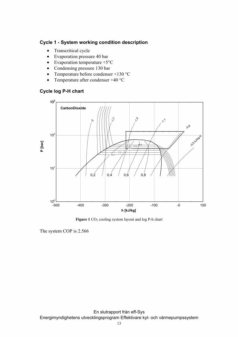
Cycle 1 - System working condition description
• Transcritical cycle • Evaporation pressure 40 bar • Evaporation temperature +5°C • Condensing pressure 130 bar • Temperature before condenser +130 °C • Temperature after condenser +40 °C
Cycle log P-H chart
-500 -400 -300 -200 -100 -0 100100
101
102
103103
h [kJ/kg]
P [b
ar]
15°C 10°C
5°C 0°C
-5°C -10°C
0,2 0,4 0,6 0,8
-2
-1,7
-1,4
-1,1
-0,8
-0,5
kJ/kg
-K
CarbonDioxide
Figure 1 CO2 cooling system layout and log P-h chart The system COP is 2.566
En slutrapport från eff-Sys Energimyndighetens utvecklingsprogram Effektivare kyl- och värmepumpssystem
13
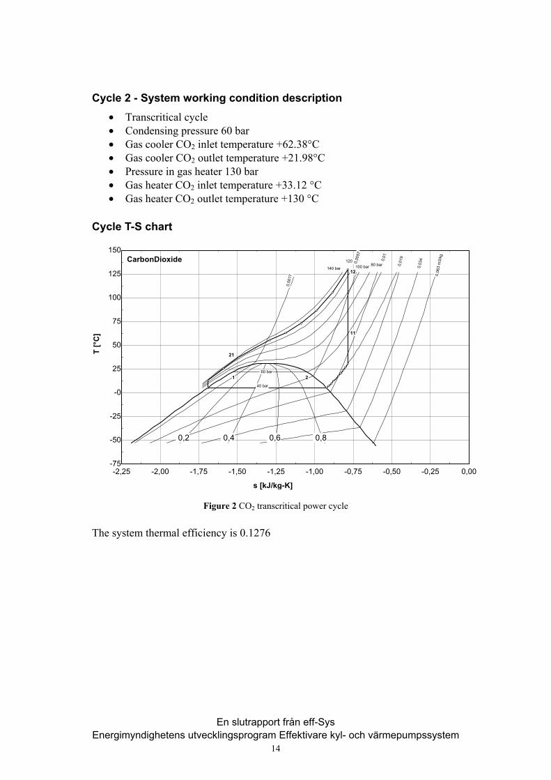
Cycle 2 - System working condition description
• Transcritical cycle • Condensing pressure 60 bar • Gas cooler CO2 inlet temperature +62.38°C • Gas cooler CO2 outlet temperature +21.98°C • Pressure in gas heater 130 bar • Gas heater CO2 inlet temperature +33.12 °C • Gas heater CO2 outlet temperature +130 °C
Cycle T-S chart
-2,25 -2,00 -1,75 -1,50 -1,25 -1,00 -0,75 -0,50 -0,25 0,00-75
-50
-25
-0
25
50
75
100
125
150
s [kJ/kg-K]
T [°
C]
140 bar
120 bar 100 bar 80 bar
60 bar
40 bar
0,2 0,4 0,6 0,8
0,0
017
0,0
057
0,0
1
0,0
19
0,0
34
0,0
63 m
3/kg
CarbonDioxide
1
21
12
11
2
Figure 2 CO2 transcritical power cycle The system thermal efficiency is 0.1276
En slutrapport från eff-Sys Energimyndighetens utvecklingsprogram Effektivare kyl- och värmepumpssystem
14
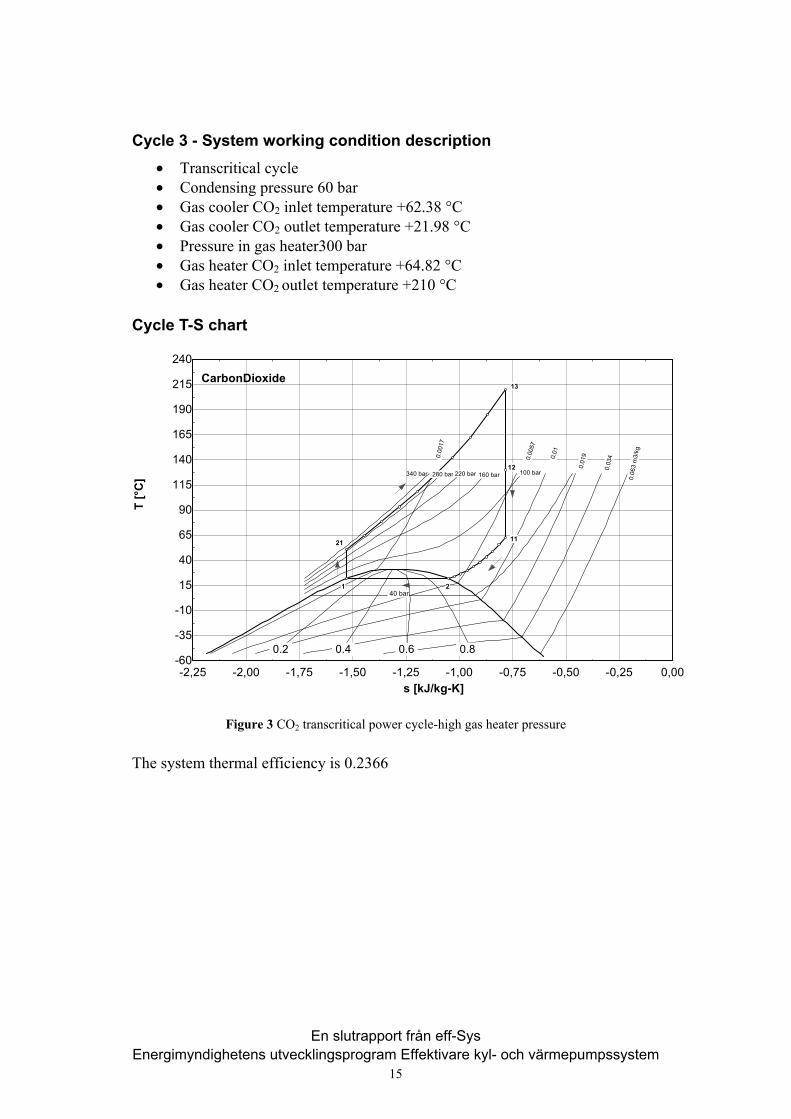
Cycle 3 - System working condition description
• Transcritical cycle • Condensing pressure 60 bar • Gas cooler CO2 inlet temperature +62.38 °C • Gas cooler CO2 outlet temperature +21.98 °C • Pressure in gas heater300 bar • Gas heater CO2 inlet temperature +64.82 °C • Gas heater CO2 outlet temperature +210 °C
Cycle T-S chart
-2,25 -2,00 -1,75 -1,50 -1,25 -1,00 -0,75 -0,50 -0,25 0,00-60
-35
-10
15
40
65
90
115
140
165
190
215
240
s [kJ/kg-K]
T [°
C] 340 bar 280 bar 220 bar 160 bar 100 bar
40 bar
0.2 0.4 0.6 0.8
0.0
017
0.0
057
0.0
1
0.0
19
0.0
34
0.0
63 m
3/kg
CarbonDioxide
1
21 11
13
2
12
Figure 3 CO2 transcritical power cycle-high gas heater pressure The system thermal efficiency is 0.2366
En slutrapport från eff-Sys Energimyndighetens utvecklingsprogram Effektivare kyl- och värmepumpssystem
15
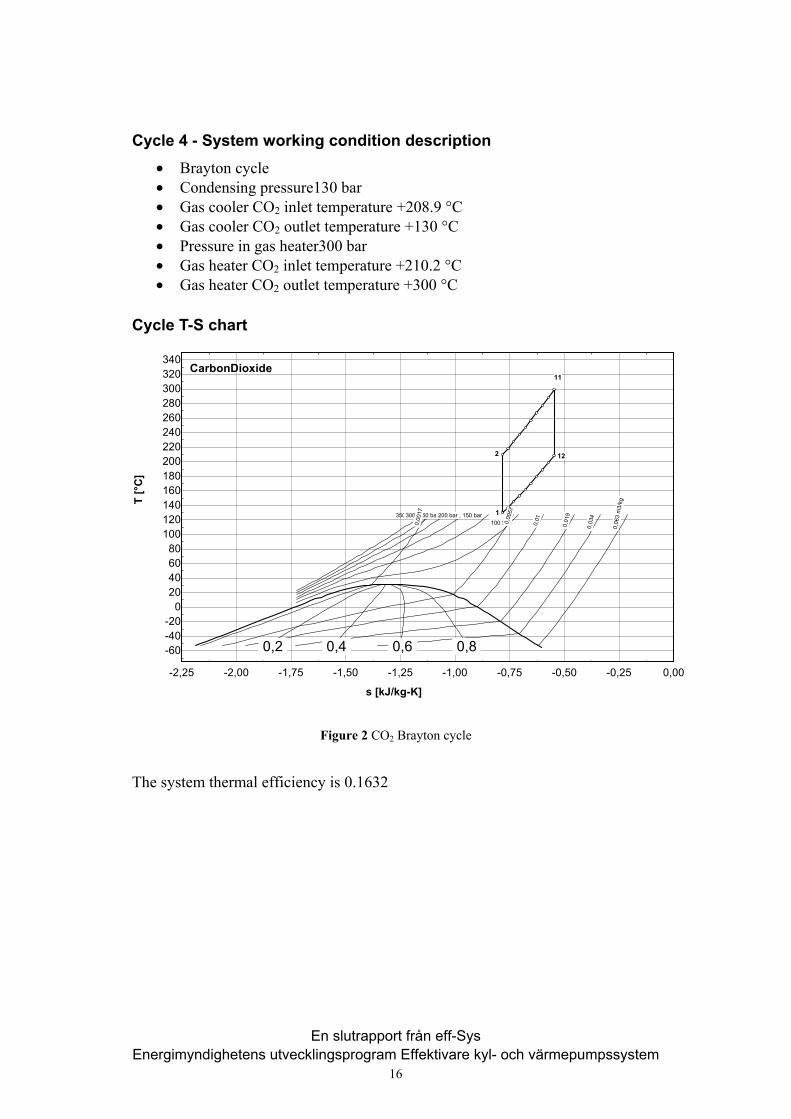
Cycle 4 - System working condition description
• Brayton cycle • Condensing pressure130 bar • Gas cooler CO2 inlet temperature +208.9 °C • Gas cooler CO2 outlet temperature +130 °C • Pressure in gas heater300 bar • Gas heater CO2 inlet temperature +210.2 °C • Gas heater CO2 outlet temperature +300 °C
Cycle T-S chart
-2,25 -2,00 -1,75 -1,50 -1,25 -1,00 -0,75 -0,50 -0,25 0,00
-60-40-20
020406080
100120140160180200220240260280300320340
s [kJ/kg-K]
T [°
C]
350 bar 300 bar 250 bar 200 bar 150 bar 100 bar
0,2 0,4 0,6 0,8
0,0
017
0,0
057
0,0
1
0,0
19
0,0
34
0,0
63 m
3/kg
CarbonDioxide
1
2
11
12
Figure 2 CO2 Brayton cycle
The system thermal efficiency is 0.1632
En slutrapport från eff-Sys Energimyndighetens utvecklingsprogram Effektivare kyl- och värmepumpssystem
16

Cycle 5- System working condition description
• Brayton cycle with reheating • Pressure in gas heater300 bar • Gas heater CO2 inlet temperature +210.2 °C • Gas heater CO2 outlet temperature +300 °C • Reheating pressure 160 bar • CO2 temperature after reheating +300 °C • Pressure in gas cooler 130 bar
Cycle T-S chart
-2,25 -2,00 -1,75 -1,50 -1,25 -1,00 -0,75 -0,50 -0,25 0,00
-60-40-20
020406080
100120140160180200220240260280300320340
s [kJ/kg-K]
T [°
C]
350 bar 300 bar 250 bar 200 bar 150 bar 100 bar
0,2 0,4 0,6 0,8
0,0
017
0,0
057
0,0
1
0,0
19
0,0
34
0,0
63 m
3/kg
CarbonDioxide
2
1
11
12
21
22
Figure 3 CO2 Brayton cycle with reheating
The system thermal efficiency is 0.1139
En slutrapport från eff-Sys Energimyndighetens utvecklingsprogram Effektivare kyl- och värmepumpssystem
17
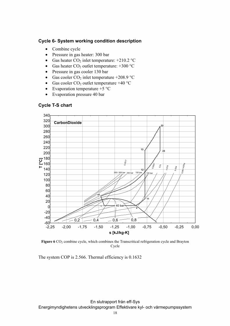
Cycle 6- System working condition description
• Combine cycle • Pressure in gas heater: 300 bar • Gas heater CO2 inlet temperature: +210.2 °C • Gas heater CO2 outlet temperature: +300 °C • Pressure in gas cooler 130 bar • Gas cooler CO2 inlet temperature +208.9 °C • Gas cooler CO2 outlet temperature +40 °C • Evaporation temperature +5 °C • Evaporation pressure 40 bar
Cycle T-S chart
-2,25 -2,00 -1,75 -1,50 -1,25 -1,00 -0,75 -0,50 -0,25 0,00-60-40-20
020406080
100120140160180200220240260280300320340
s [kJ/kg-K]
T [°
C]
350 bar 300 bar 250 bar 150 bar 100 bar
40 bar
0,2 0,4 0,6 0,8
0,0
017
0,0
057
0,0
1
0,0
19
0,0
34
0,0
63 m
3/kg
CarbonDioxide
12
11
12
13
22
23
41
Figure 6 CO2 combine cycle, which combines the Transcritical refrigeration cycle and Brayton Cycle
The system COP is 2.566. Thermal efficiency is 0.1632
En slutrapport från eff-Sys Energimyndighetens utvecklingsprogram Effektivare kyl- och värmepumpssystem
18
The heat exchangers – stage 2
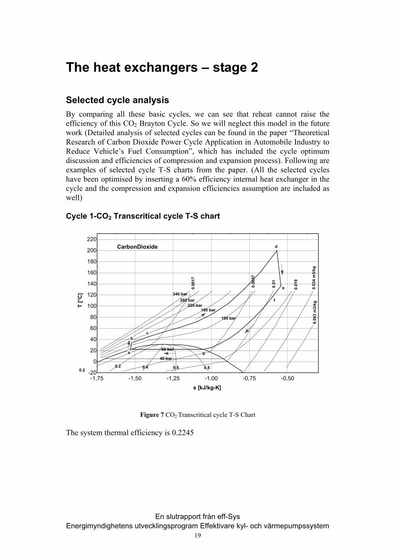
Selected cycle analysis By comparing all these basic cycles, we can see that reheat cannot raise the efficiency of this CO2 Brayton Cycle. So we will neglect this model in the future work (Detailed analysis of selected cycles can be found in the paper “Theoretical Research of Carbon Dioxide Power Cycle Application in Automobile Industry to Reduce Vehicle’s Fuel Consumption”, which has included the cycle optimum discussion and efficiencies of compression and expansion process). Following are examples of selected cycle T-S charts from the paper. (All the selected cycles have been optimised by inserting a 60% efficiency internal heat exchanger in the cycle and the compression and expansion efficiencies assumption are included as well)
Cycle 1-CO2 Transcritical cycle T-S chart
-1,75 -1,50 -1,25 -1,00 -0,75 -0,50-20
0
20
40
60
80
100
120
140
160
180
200
220
s [kJ/kg-K]
T [°
C] 340 bar
280 bar 220 bar
160 bar
100 bar
40 bar
0.2 0.4 0.6 0.8
0.0
017
0.0
057
0.0
1
0.0
19
0.0
34 m
3/kg
0.0
63 m
3/kg
CarbonDioxide
a
bc
d
e
f
g 60 bar
0.2
Figure 7 CO2 Transcritical cycle T-S Chart The system thermal efficiency is 0.2245
En slutrapport från eff-Sys Energimyndighetens utvecklingsprogram Effektivare kyl- och värmepumpssystem
19
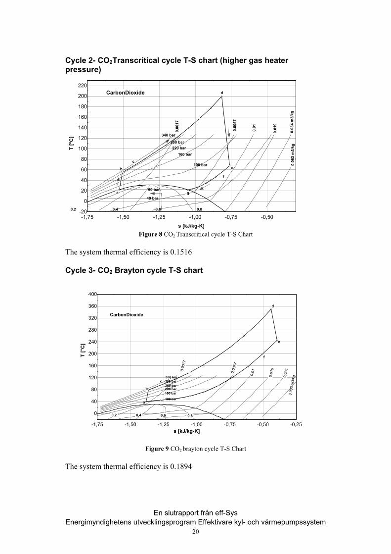
Cycle 2- CO2Transcritical cycle T-S chart (higher gas heater pressure)
-1,75 -1,50 -1,25 -1,00 -0,75 -0,50-20
0
20
40
60
80
100
120
140
160
180
200
220
s [kJ/kg-K]
T [°
C] 340 bar
280 bar 220 bar
160 bar
100 bar
40 bar
0.2 0.4 0.6 0.8
0.0
017
0.0
057
0.0
1
0.0
19
0.0
34 m
3/kg
0.0
63 m
3/kg
CarbonDioxide
a
b
c
d
e
f
g 60 bar
Figure 8 CO2 Transcritical cycle T-S Chart
The system thermal efficiency is 0.1516
Cycle 3- CO2 Brayton cycle T-S chart
-1,75 -1,50 -1,25 -1,00 -0,75 -0,50 -0,25
0
40
80
120
160
200
240
280
320
360
400
s [kJ/kg-K]
T [°
C]
350 bar 300 bar 250 bar 200 bar 150 bar
100 bar
0,2 0,4 0,6 0,8
0,0
017
0,0
057
0,0
1
0,0
19
0,0
34
0,0
63 m
3/kg
CarbonDioxide
a
b
c
d
e
f
Figure 9 CO2 brayton cycle T-S Chart
The system thermal efficiency is 0.1894
En slutrapport från eff-Sys Energimyndighetens utvecklingsprogram Effektivare kyl- och värmepumpssystem
20
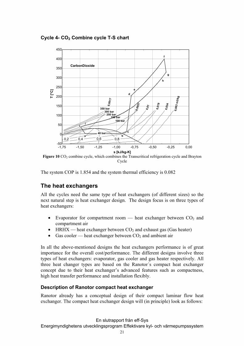
Cycle 4- CO2 Combine cycle T-S chart
Figure 10 CO2 combine cycle, which combines the Transcritical refrigeration cycle and Brayton Cycle
-1,75 -1,50 -1,25 -1,00 -0,75 -0,50 -0,25 0,00-50
0
50
100
150
200
250
300
350
400
450
s [kJ/kg-K]
T [°
C]
350 bar 300 bar
250 bar 150 bar
100 bar
40 bar
0,2 0,4 0,6 0,8
0,0
017
0,0
057
0,0
1
0,0
19
0,0
34
0,0
63 m
3/kg
CarbonDioxide
a b
de
f
c
i
g
j
h
The system COP is 1.854 and the system thermal efficiency is 0.082
The heat exchangers All the cycles need the same type of heat exchangers (of different sizes) so the next natural step is heat exchanger design. The design focus is on three types of heat exchangers:
• Evaporator for compartment room — heat exchanger between CO2 and compartment air
• HRHX — heat exchanger between CO2 and exhaust gas (Gas heater) • Gas cooler — heat exchanger between CO2 and ambient air
In all the above-mentioned designs the heat exchangers performance is of great importance for the overall cost/performance. The different designs involve three types of heat exchangers: evaporator, gas cooler and gas heater respectively. All three heat changer types are based on the Ranotor´s compact heat exchanger concept due to their heat exchanger’s advanced features such as compactness, high heat transfer performance and installation flexibly.
Description of Ranotor compact heat exchanger Ranotor already has a conceptual design of their compact laminar flow heat exchanger. The compact heat exchanger design will (in principle) look as follows:
En slutrapport från eff-Sys Energimyndighetens utvecklingsprogram Effektivare kyl- och värmepumpssystem
21
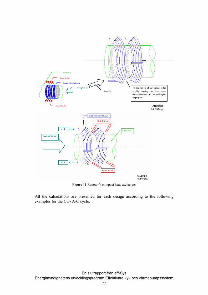
Figure 11 Ranotor’s compact heat exchanger
All the calculations are presented for each design according to the following examples for the CO2 A/C cycle.
En slutrapport från eff-Sys Energimyndighetens utvecklingsprogram Effektivare kyl- och värmepumpssystem
22
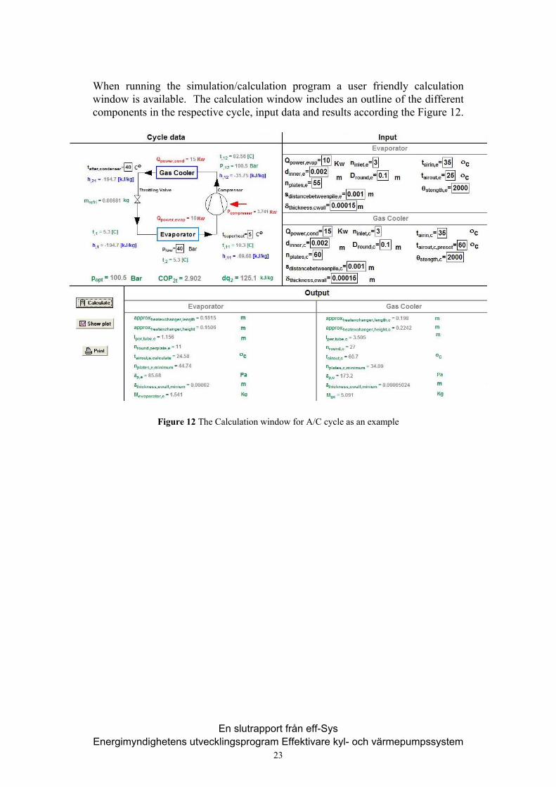
When running the simulation/calculation program a user friendly calculation window is available. The calculation window includes an outline of the different components in the respective cycle, input data and results according the Figure 12.
Figure 12 The Calculation window for A/C cycle as an example
En slutrapport från eff-Sys Energimyndighetens utvecklingsprogram Effektivare kyl- och värmepumpssystem
23
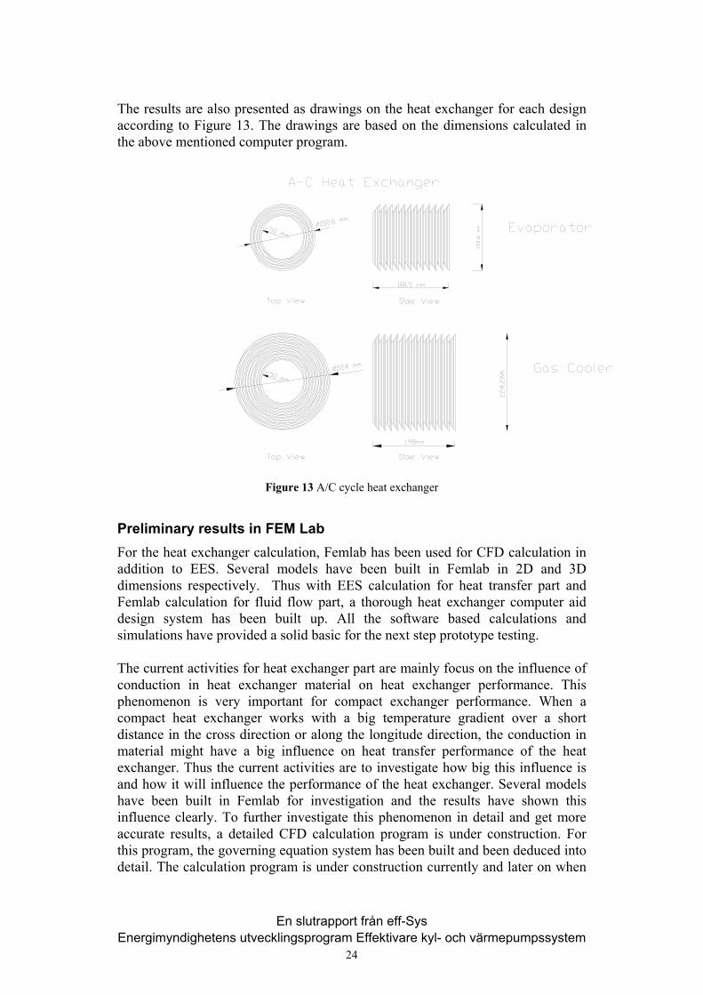
The results are also presented as drawings on the heat exchanger for each design according to Figure 13. The drawings are based on the dimensions calculated in the above mentioned computer program.
Figure 13 A/C cycle heat exchanger
Preliminary results in FEM Lab For the heat exchanger calculation, Femlab has been used for CFD calculation in addition to EES. Several models have been built in Femlab in 2D and 3D dimensions respectively. Thus with EES calculation for heat transfer part and Femlab calculation for fluid flow part, a thorough heat exchanger computer aid design system has been built up. All the software based calculations and simulations have provided a solid basic for the next step prototype testing. The current activities for heat exchanger part are mainly focus on the influence of conduction in heat exchanger material on heat exchanger performance. This phenomenon is very important for compact exchanger performance. When a compact heat exchanger works with a big temperature gradient over a short distance in the cross direction or along the longitude direction, the conduction in material might have a big influence on heat transfer performance of the heat exchanger. Thus the current activities are to investigate how big this influence is and how it will influence the performance of the heat exchanger. Several models have been built in Femlab for investigation and the results have shown this influence clearly. To further investigate this phenomenon in detail and get more accurate results, a detailed CFD calculation program is under construction. For this program, the governing equation system has been built and been deduced into detail. The calculation program is under construction currently and later on when
En slutrapport från eff-Sys Energimyndighetens utvecklingsprogram Effektivare kyl- och värmepumpssystem
24
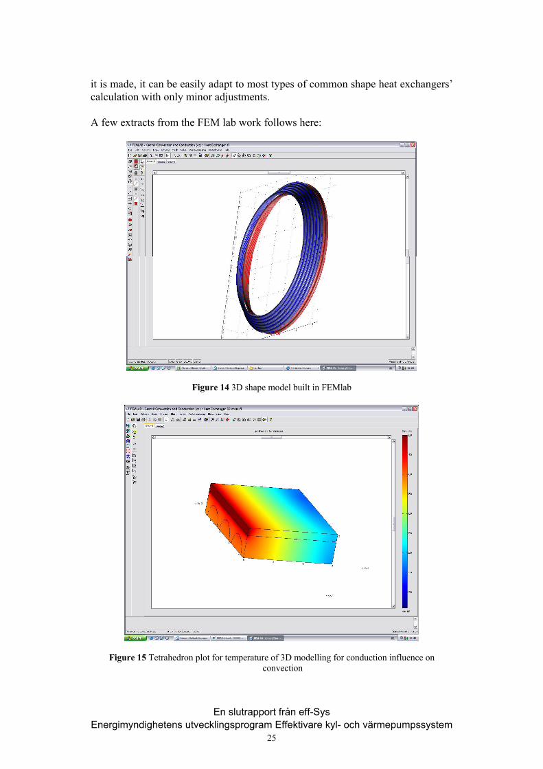
it is made, it can be easily adapt to most types of common shape heat exchangers’ calculation with only minor adjustments. A few extracts from the FEM lab work follows here:
Figure 14 3D shape model built in FEMlab
Figure 15 Tetrahedron plot for temperature of 3D modelling for conduction influence on convection
En slutrapport från eff-Sys Energimyndighetens utvecklingsprogram Effektivare kyl- och värmepumpssystem
25
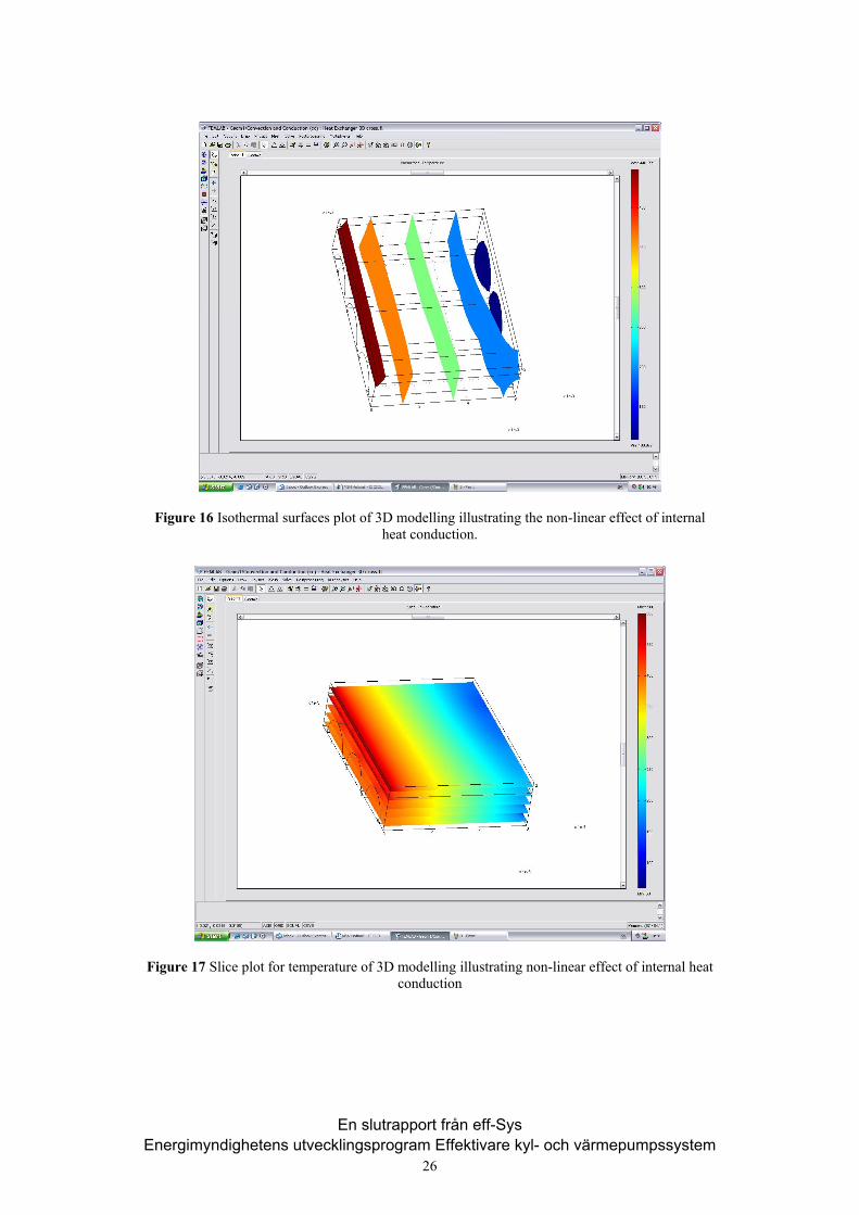
Figure 16 Isothermal surfaces plot of 3D modelling illustrating the non-linear effect of internal heat conduction.
Figure 17 Slice plot for temperature of 3D modelling illustrating non-linear effect of internal heat conduction
En slutrapport från eff-Sys Energimyndighetens utvecklingsprogram Effektivare kyl- och värmepumpssystem
26
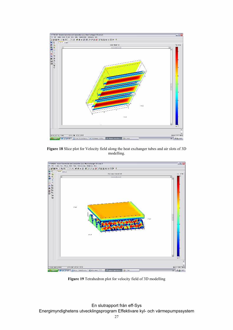
Figure 18 Slice plot for Velocity field along the heat exchanger tubes and air slots of 3D modelling.
Figure 19 Tetrahedron plot for velocity field of 3D modelling
En slutrapport från eff-Sys Energimyndighetens utvecklingsprogram Effektivare kyl- och värmepumpssystem
27
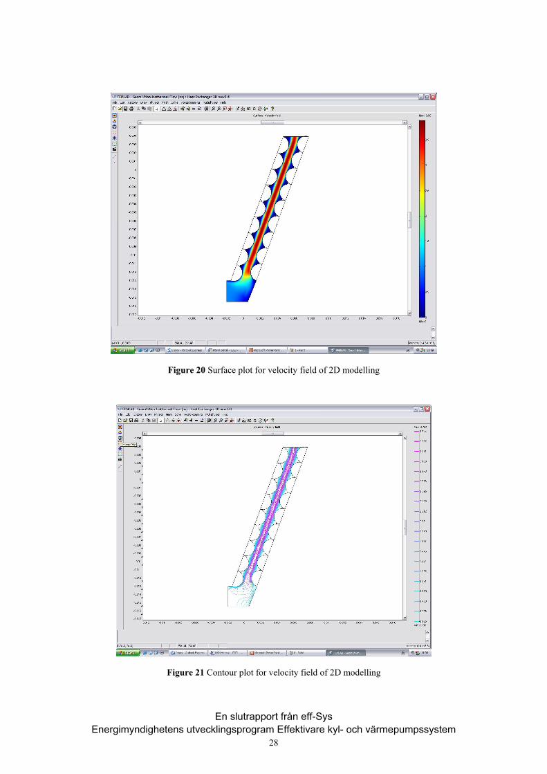
Figure 20 Surface plot for velocity field of 2D modelling
Figure 21 Contour plot for velocity field of 2D modelling
En slutrapport från eff-Sys Energimyndighetens utvecklingsprogram Effektivare kyl- och värmepumpssystem
28
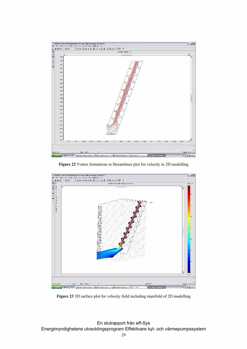
Figure 22 Vortex formations in Streamlines plot for velocity in 2D modelling
Figure 23 3D surface plot for velocity field including manifold of 2D modelling
En slutrapport från eff-Sys Energimyndighetens utvecklingsprogram Effektivare kyl- och värmepumpssystem
29
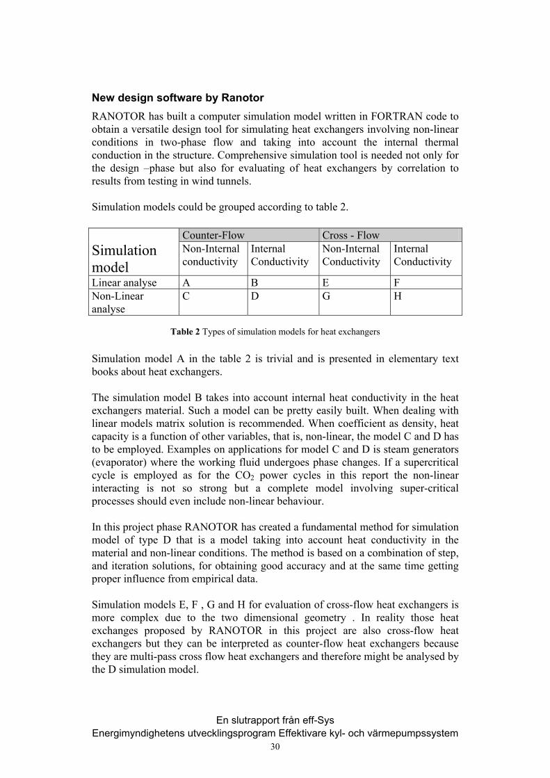
New design software by Ranotor RANOTOR has built a computer simulation model written in FORTRAN code to obtain a versatile design tool for simulating heat exchangers involving non-linear conditions in two-phase flow and taking into account the internal thermal conduction in the structure. Comprehensive simulation tool is needed not only for the design –phase but also for evaluating of heat exchangers by correlation to results from testing in wind tunnels. Simulation models could be grouped according to table 2.
Counter-Flow Cross - Flow Simulation model
Non-Internal conductivity
Internal Conductivity
Non-Internal Conductivity
Internal Conductivity
Linear analyse A B E F Non-Linear analyse
C D G H
Table 2 Types of simulation models for heat exchangers
Simulation model A in the table 2 is trivial and is presented in elementary text books about heat exchangers. The simulation model B takes into account internal heat conductivity in the heat exchangers material. Such a model can be pretty easily built. When dealing with linear models matrix solution is recommended. When coefficient as density, heat capacity is a function of other variables, that is, non-linear, the model C and D has to be employed. Examples on applications for model C and D is steam generators (evaporator) where the working fluid undergoes phase changes. If a supercritical cycle is employed as for the CO2 power cycles in this report the non-linear interacting is not so strong but a complete model involving super-critical processes should even include non-linear behaviour. In this project phase RANOTOR has created a fundamental method for simulation model of type D that is a model taking into account heat conductivity in the material and non-linear conditions. The method is based on a combination of step, and iteration solutions, for obtaining good accuracy and at the same time getting proper influence from empirical data. Simulation models E, F , G and H for evaluation of cross-flow heat exchangers is more complex due to the two dimensional geometry . In reality those heat exchanges proposed by RANOTOR in this project are also cross-flow heat exchangers but they can be interpreted as counter-flow heat exchangers because they are multi-pass cross flow heat exchangers and therefore might be analysed by the D simulation model.
En slutrapport från eff-Sys Energimyndighetens utvecklingsprogram Effektivare kyl- och värmepumpssystem
30
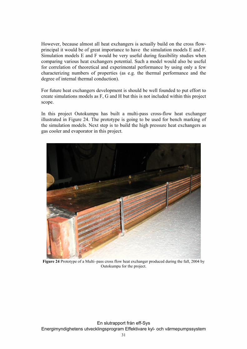
However, because almost all heat exchangers is actually build on the cross flow-principal it would be of great importance to have the simulation models E and F. Simulation models E and F would be very useful during feasibility studies when comparing various heat exchangers potential. Such a model would also be useful for correlation of theoretical and experimental performance by using only a few characterizing numbers of properties (as e.g. the thermal performance and the degree of internal thermal conduction). For future heat exchangers development is should be well founded to put effort to create simulations models as F, G and H but this is not included within this project scope. In this project Outokumpu has built a multi-pass cross-flow heat exchanger illustrated in Figure 24. The prototype is going to be used for bench marking of the simulation models. Next step is to build the high pressure heat exchangers as gas cooler and evaporator in this project.
Figure 24 Prototype of a Multi–pass cross flow heat exchanger produced during the fall, 2004 by Outokumpu for the project.
En slutrapport från eff-Sys Energimyndighetens utvecklingsprogram Effektivare kyl- och värmepumpssystem
31
Industrial relevance The project has been carried out in close co-operation with RANOTOR Company which is an R & D Company and Visteon that an automotive sub supplier, who manufacturing and marketing Air-Conditioning units with CO2 as working fluid. As a discussion partner when it comes to the concepts viability and market attractiveness in heavy-duty truck applications has Scania and Volvo truck participated. The heat exchangers design and possibility to manufacture has also been discussed with Industrimekanik Company, an engineering consultancy company but recently more intense with Outokumpu. Competence regarding compressor and expander technologies has been brought in by SRM AB.
Energy relevance One of the aims with this project was to identify possibilities to harness waste heat from the internal combustion engine and thus reducing energy consumption. The results indicate that about 10-15 % of the waste heat from the internal combustion engine could be recovered in a bottoming cycle employing CO2 as working fluid.
Environmental relevance The environment relevancies are numerous. Firstly, using CO2 as the working fluid gives low GWP and non-ODP working fluid. Secondly, the waste heat recovery reduces the amount of fossil fuel expended. Thirdly, when the exhaust gas heat is recovered the exhaust gas is also cooled down. This so-called cold EGR (Exhaust Gas Recirculation) is an efficient way to further suppress NOx emissions. Fourthly, by using the A/C as an APU, it is possible to generate electricity even when the vehicle is standing still and thus heat and cool the vehicle in a more environmental way than operating the large diesel engine at part load.
International co-operation The Visteon Company is a global automotive sub supplier with divisions worldwide. So far only a Germany Visteon company has been participated but further work will also involve other companies working with the compressor for instance. The work has also involved some contacts with SINTEF in Norway. Further work towards commercialisation will probably involve several companies outside Sweden but Swedish automotive manufactures is expected to participate when prototypes is going to be tested. EU projects are also promoted.
En slutrapport från eff-Sys Energimyndighetens utvecklingsprogram Effektivare kyl- och värmepumpssystem
32
Dissemination of the results The results will be further disseminated to CO2-A/C manufactures and automotive manufactures in order to attract further investment for commercialisation of the concept. Two scientific papers have been written and EES programs have been further modified to calculate the second law efficiency etc. to meet the papers’ requirements. These two scientific papers are “Theoretical Research of Carbon Dioxide Power Cycle Application in Automobile Industry to Reduce Vehicle’s Fuel Consumption”, which has been submitted to scientific journal “Applied Thermal Engineering” and “Waste Heat Recovery Ability Comparison between Organic Rankine Cycle and Carbon Dioxide Transcritical Cycle”, which is currently under correction respectively. The paper “Theoretical Research of Carbon Dioxide Power Cycle Application in Automobile Industry to Reduce Vehicle’s Fuel Consumption” discusses the means to utilize low-grade small-scale energy in vehicle exhaust gas to reduce the vehicle’s fuel consumption and to make it run more environmental friendly. A multi-functional vehicle’s A/C system is proposed by the authors to convert this energy into useful power to power the compressor of A/C system or even to be added to the propulsion system. According to different design options, several cycles are presented and compared; the relative efficiencies are calculated in EES as well. At the end of the paper, there is a thorough discussion about the CO2’s thermodynamic properties as a working fluid and the cycles’ optimisation issues. The paper “Waste Heat Recovery Ability Comparison between Organic Rankine Cycle and Carbon Dioxide Transcritical Cycle” discusses the low grade waste heat recovery potential between CO2 transcritical power cycle and the ORC (Organic Rankine Cycle). In the paper, the first law and the second law efficiency for both cycles are calculated in EES and then compared. The second law efficiency is redefined to fit the specified cycles’ characters, when they have gradient heat addition or heat rejection temperatures. The results show that the CO2 transcritical power cycle is more potential than the ORC to recovery the low-grade waste heat with a gradient temperature, due to the reason that its heat addition character “fits” the heat source character better than ORC. 15% more efficient than ORC for a typical case calculation in the paper for instance.
En slutrapport från eff-Sys Energimyndighetens utvecklingsprogram Effektivare kyl- och värmepumpssystem
33
References
[1] Eric Granryd el., “Refrigeration Engineering”, Royal Institute of technology, Sweden Chapter 5 pp5: 16 [2] Jostein PETTERSEN and Rune AARLIEN, “Progress in CO2 Vapour Compression System” Thermal Science & Engineering Vol, 6 No1 (1998) [3] Mr. Casini Dorin, “CO2 compressors and Equipment, Use and Availability” EURO Cooling and Heating Centro Study Galileo [4] Friedrich Kauf, “Determination of the optimum high pressure for transcritical CO2-refrigeration cycles” Int.J.Therm. Sci. (1999) 38,325-330 [5] S.M. Liao, T.S. Zhao, and A.Jalobsen, “A correlation of optimal heat rejection pressures in transcritical carbon cycles” Applied Thermal Engineering 20 (2000) 831-841 [6] J. Pettersen, A. Hafner and G. skaugen, “Development of Compact Heat Exchangers for CO2 Air-conditioning Systems” SINTEF Energy Research, Refrigeration and Air Conditioning N-7034 Trondheim, Norway [7] Srinivas S. Pitla, Eckhard A. Groll, Satish Ramadhyani, “New correlation to predict the heat transfer coefficient during in-tube cooling of turbulent supercritical CO2” International Journal of refrigeration 25(2002) 887-895 [8] Jian Min Yin, Clark W. Bullard, Predrag S. Hrnjak, “R-744 gas cooler model development and validation” Air conditioning and Refrigeration Centre, 1206 W. Green street, University of Illinois at Urbana-Champaign, Urbana, IL 61801,USA [9] Man-Hoe Kim, Clark W., “Bullard Development of a micro channel evaporator model for a CO2 air-conditioning system” Department of mechanical and Industrial Engineering, University of Illinois, 1206 West Greet Street, Urbana, IL 61801,USA Energy 26(2001) 931-948 [10] Jostein Pettersen, “Flow vaporization of CO2 in microchannel tubes” Department of Refrigeration and Air Conditioning, Norwegian University of science and Technology, Trondheim No-7491, Norway [11] Sivert Vist, Jostein Pettersen, “Two-phase flow distribution in compact heat exchanger manifolds” Department of Refrigeration and Air Conditioning, Norwegian University of science and Technology, Trondheim No-7491, Norway [12] Rin Yun, Yongchan Kim, Min Soo Kim, Youngdon Choi, “Boiling heat transfer and dryout phenomenon of CO2 in a horizontal smooth tube” Department of Mechanical Engineering, Korean University, Anam-dong, Sungbuk-ku, Seoul 136-701,South Korean, Department of Mechanical and Aerospace Engineering, Seoul National University, Seoul 151-744,South Korean, International Journal of Heat and Mass Transfer 46(2003) 2353-2361 [13] G. Scalabrin.L.Piazza, “Analysis of forced convection heat transfer to supercritical carbon dioxide inside tubes using neutral networks” International Journal of Heat and Mass Transfer 46(2003) 1139-1154 [14] G.Scalabrin, L.Piazza, M.condonsta, “Convective cooling of supercritical carbon dioxide inside tubes: heat transfer analysis through neural networks” International Journal of Heat and Mass Transfer 46(2003) 4413-4425
En slutrapport från eff-Sys Energimyndighetens utvecklingsprogram Effektivare kyl- och värmepumpssystem
34

[15] J. Pettersen, A, Hafner and G. Skaugen, “Development of compact heat exchanger for CO2 air-conditioning systems” SINTEF Energy Research, Refrigeration and Air-Conditioning N-7034 Trondheim Norway. PII: s0140-7007 (98) 00013-9 [16] J. –H. Ko, M.E. Ewing, Y.G. Guezennec, R.N. Christensen, “Development of a low Reynolds number enhanced heat transfer surface using flow visualization techniques” Mechanical Engineering Department, Ohio State University, 206 W 18th Avenue, Columbus, OH 43210,USA International Journal of Heat and Fluid Flow 23 (2002) 444-454 [17] Peter A. Kew and Keith Cornwell, “Correlations for the prediction of boiling heat transfer in small-diameter channels” Department of mechanical and chemical Engineering, Heriot-Watt University, Edinburgh, Eh 14 4AS, UK.PII: S 1359-4311(96) 00071-3 [18] Sung-Ho Choi, Won-Ho Cho, Ju-Won Kim, Jong-Soo Kim, “A study on the development of the wire woven heat exchanger using small diameter tubes” Graduate School of Pukyong National University, Busan 608-737,South Korean; Pukyong National University, Busan 608-737,South Korean [19] Andrey Rozhentsev, Chi –Chuan Wang, “Some design features of a CO2 air conditioner” Energy and Resources Laboratories, Industrial Technology Research Institute, D400 ERL/ITRI. Building 64, 195-6 Section 4,Chung Hsing Road, Chutung, Hsinchu 310,Taiwan, ROC. Applied Thermal Engineering 21 (2001) 871-880 [20] J. Steven Brown, Samuel F. Yana-Motta, Piotr A. Domanski, “Comparative analysis of automotive air conditioning systems operating with CO2 and R134a” International Journal of Refrigeration 25 (2002) 19-32 [21] A.Hafner and J Pettersen, G. Skaugen, P. Nekså, “An Automobile HVAC System with CO2 as the Refrigerant” Refrigeration and Air Conditioning, N-7034 Trondheim, Norway [22] “CO2-A/C-System COP Comparison R134a vs. CO2” VOLKSWAGEN [23] Douglas M.Robinson and Eckhard A. Groll, “Efficiencies of transcritical CO2 cycles with and without an expansion turbine” Ray W. Herrick Laboraties, Purdue University, West Lafayette, IN 47907-1077,USA .PII: S0140-7007 (98) 00024-3 [24] Shitong Zha, Yitai Ma, Xi Sun, “The development of CO2 expander in CO2 transcritical cycles” ICR 0089 [25] Shitong Zha, Yitai Ma, “CO2 Expanding Progress For CO2 Transcritical Cycle” ICR 0090 [26] J. Nickl, G. Will, W.E. Kraus, H. Quack, “Third Generation CO2 Expander” ICR 0571 [27] E.G. FEHER, “The Supercritical Thermodynamic Power Cycle Energy” Conversion Vol.8.pp 85-90 [28] Promotion Of Co-generation Power Plants - 6th Nov '1996 http://www.indiainfoline.com/infr/lapo/poli/capt/pcpp/deta.html[29] Strength of Materials-A New Unified Theory for the 21st Century 2004 ISBN 0-7506-7402-4(alk.paper)
En slutrapport från eff-Sys Energimyndighetens utvecklingsprogram Effektivare kyl- och värmepumpssystem
35

[30] E.A.Foumeny and P.J.Hegys Heat Exchanger Engineering Volume 2― Compact Heat Exchangers ISBN 0-13-382391-1.
En slutrapport från eff-Sys Energimyndighetens utvecklingsprogram Effektivare kyl- och värmepumpssystem
36