coal gasification and igcc in europe
TRANSCRIPT

Coal gasificationand IGCC in Europe
Stephen J Mills
CCC/113
June 2006
Copyright © IEA Clean Coal Centre
ISBN 92-9029-429-9
Abstract
This report provides an overview of major coal based IGCC plantscurrently operating in Europe. For each plant, details are provided oftechnology adopted, major components, operational experience andproblems encountered, plant updates installed and modifications made,and environmental performance. Where available, information onpossible future developments has been provided. This is followed by anexamination of European plants either gasifying coal or cogasifying coalwith other feedstocks. The final section provides a review of Europeanrefinery based IGCC plants operating on low value refinery by-products.
Acknowledgements
The contribution of Marco Kanaar of Nuon and Piet Zuideveld of ShellGlobal Solutions International BV in the preparation of this report isgratefully acknowledged
This report was sponsored by the New Energy andIndustrial Development Organization (NEDO), Japan

Acronyms and abbreviationsASU air separation unitBGL British Gas/LurgiCSLF Carbon Sequestration Leadership ForumCV calorific valueDGAN diluent nitrogen injectionDCS distributed control systemsECBM enhanced coalbed methane (recovery)EOR enhanced oil recovery FW Foster WheelerFT Fischer TropschGE General ElectricHGCU hot gas clean-upHHV higher heating valueHP high pressureHRSG heat recovery steam generatorHTW high temperature WinklerIGCC integrated gasification combined cycleLHV lower heating valueLP low pressureLLB Lurgi Lentjes BabcockMBM meat and bone mealMCFC molten carbonate fuel cellMDEA methyldiethanolamineMP medium pressureMPa megapascalsMWe megawatts (electrical)MWth megawatts (thermal)NOx oxides of nitrogenPC pulverised coalSOFC solid oxide fuel cell
IEA Clean Coal Centre2
Contents
Acronyms and abbreviations. . . . . . . . . . . . . . . . . . . . . . . . . . . . . . . . . . . . . . . . . . . . . . . . 2
Contents. . . . . . . . . . . . . . . . . . . . . . . . . . . . . . . . . . . . . . . . . . . . . . . . . . . . . . . . . . . . . . . . 3
List of figures . . . . . . . . . . . . . . . . . . . . . . . . . . . . . . . . . . . . . . . . . . . . . . . . . . . . . . . . . . . 5
List of tables . . . . . . . . . . . . . . . . . . . . . . . . . . . . . . . . . . . . . . . . . . . . . . . . . . . . . . . . . . . . 6
1 Introduction . . . . . . . . . . . . . . . . . . . . . . . . . . . . . . . . . . . . . . . . . . . . . . . . . . . . . . . . . 7
2 The Willem Alexander IGCC plant, Buggenum, The Netherlands . . . . . . . . . . . . . . 82.1 Background . . . . . . . . . . . . . . . . . . . . . . . . . . . . . . . . . . . . . . . . . . . . . . . . . . 82.2 Fuels . . . . . . . . . . . . . . . . . . . . . . . . . . . . . . . . . . . . . . . . . . . . . . . . . . . . . 82.3 Gasification technology . . . . . . . . . . . . . . . . . . . . . . . . . . . . . . . . . . . . . . . . . 92.4 Balance of plant . . . . . . . . . . . . . . . . . . . . . . . . . . . . . . . . . . . . . . . . . . . . . . 10
2.4.1 Coal preparation facility . . . . . . . . . . . . . . . . . . . . . . . . . . . . . . . . . 102.4.2 Wastewater treatment plant . . . . . . . . . . . . . . . . . . . . . . . . . . . . . . 102.4.3 Combined cycle facility . . . . . . . . . . . . . . . . . . . . . . . . . . . . . . . . . 112.4.4 Hot gas filter (see below) . . . . . . . . . . . . . . . . . . . . . . . . . . . . . . . . 11
2.5 Hot gas clean-up system . . . . . . . . . . . . . . . . . . . . . . . . . . . . . . . . . . . . . . . 112.6 Operating experience and plant modifications . . . . . . . . . . . . . . . . . . . . . . 112.7 Environmental performance. . . . . . . . . . . . . . . . . . . . . . . . . . . . . . . . . . . . . 122.8 Production of biofuels by Fischer-Tropsch synthesis . . . . . . . . . . . . . . . . . 122.9 Possible future activities . . . . . . . . . . . . . . . . . . . . . . . . . . . . . . . . . . . . . . . 132.10 Next generation plant. . . . . . . . . . . . . . . . . . . . . . . . . . . . . . . . . . . . . . . . . . 132.11 Summary . . . . . . . . . . . . . . . . . . . . . . . . . . . . . . . . . . . . . . . . . . . . . . . . . . . 13
3 Puertollano IGCC plant, Puertollano, Spain . . . . . . . . . . . . . . . . . . . . . . . . . . . . . . . 143.1 Background . . . . . . . . . . . . . . . . . . . . . . . . . . . . . . . . . . . . . . . . . . . . . . . . . 143.2 Fuel . . . . . . . . . . . . . . . . . . . . . . . . . . . . . . . . . . . . . . . . . . . . . . . . . . . . 153.3 Gasification technology . . . . . . . . . . . . . . . . . . . . . . . . . . . . . . . . . . . . . . . . 163.4 Balance of plant . . . . . . . . . . . . . . . . . . . . . . . . . . . . . . . . . . . . . . . . . . . . . . 163.5 Hot gas filter . . . . . . . . . . . . . . . . . . . . . . . . . . . . . . . . . . . . . . . . . . . . . . . . 183.6 Operating experience and plant modifications . . . . . . . . . . . . . . . . . . . . . . 18
3.6.1 Fuel preparation and feeding systems . . . . . . . . . . . . . . . . . . . . . . 183.6.2 Gasifier . . . . . . . . . . . . . . . . . . . . . . . . . . . . . . . . . . . . . . . . . . . . . . 193.6.3 Air separation unit . . . . . . . . . . . . . . . . . . . . . . . . . . . . . . . . . . . . . 193.6.4 Waste heat boiler . . . . . . . . . . . . . . . . . . . . . . . . . . . . . . . . . . . . . . 203.6.5 Slag removal system. . . . . . . . . . . . . . . . . . . . . . . . . . . . . . . . . . . . 203.6.6 Gas turbine . . . . . . . . . . . . . . . . . . . . . . . . . . . . . . . . . . . . . . . . . . . 203.6.7 Hot gas filter . . . . . . . . . . . . . . . . . . . . . . . . . . . . . . . . . . . . . . . . . . 203.6.8 Syngas clean-up . . . . . . . . . . . . . . . . . . . . . . . . . . . . . . . . . . . . . . . 20
3.7 Environmental performance. . . . . . . . . . . . . . . . . . . . . . . . . . . . . . . . . . . . . 203.8 ELCOGAS R&D activities . . . . . . . . . . . . . . . . . . . . . . . . . . . . . . . . . . . . . 21
3.8.1 Hydrogen production and CO2 capture . . . . . . . . . . . . . . . . . . . . . 213.8.2 Development of advanced information systems. . . . . . . . . . . . . . . 223.8.3 Utilisation of plant fly ash and slag . . . . . . . . . . . . . . . . . . . . . . . . 223.8.4 Improvements to hot gas filtration system . . . . . . . . . . . . . . . . . . . 223.8.5 Urban solid wastes and biomass cogasification . . . . . . . . . . . . . . 22
3.9 Possible future activities . . . . . . . . . . . . . . . . . . . . . . . . . . . . . . . . . . . . . . . 223.10 Next generation plant. . . . . . . . . . . . . . . . . . . . . . . . . . . . . . . . . . . . . . . . . . 233.11 Summary . . . . . . . . . . . . . . . . . . . . . . . . . . . . . . . . . . . . . . . . . . . . . . . . . . . 23
4 Vresova IGCC plant, Czech Republic . . . . . . . . . . . . . . . . . . . . . . . . . . . . . . . . . . . 254.1 Background . . . . . . . . . . . . . . . . . . . . . . . . . . . . . . . . . . . . . . . . . . . . . . . . . 254.2 Technology. . . . . . . . . . . . . . . . . . . . . . . . . . . . . . . . . . . . . . . . . . . . . . . . . . 254.3 Emission control . . . . . . . . . . . . . . . . . . . . . . . . . . . . . . . . . . . . . . . . . . . . . 254.4 Future plans . . . . . . . . . . . . . . . . . . . . . . . . . . . . . . . . . . . . . . . . . . . . . . . . . 25
5 ATI Sulcis, Sardinia, Italy . . . . . . . . . . . . . . . . . . . . . . . . . . . . . . . . . . . . . . . . . . . . . 27
Coal gasification and IGCC in Europe 3

6 Other coal based gasification plants in Europe. . . . . . . . . . . . . . . . . . . . . . . . . . . . . 286.1 Fife Power, Scotland, UK . . . . . . . . . . . . . . . . . . . . . . . . . . . . . . . . . . . . . . 286.2 Schwarze Pumpe plant, Germany . . . . . . . . . . . . . . . . . . . . . . . . . . . . . . . . 28
6.2.1 Fuels . . . . . . . . . . . . . . . . . . . . . . . . . . . . . . . . . . . . . . . . . . . . . . . . 296.2.2 Gasification technology . . . . . . . . . . . . . . . . . . . . . . . . . . . . . . . . . 296.2.3 Balance of plant . . . . . . . . . . . . . . . . . . . . . . . . . . . . . . . . . . . . . . . 306.2.4 Future site developments . . . . . . . . . . . . . . . . . . . . . . . . . . . . . . . . 31
6.3 Gorazde ammonia plant, Bosnia . . . . . . . . . . . . . . . . . . . . . . . . . . . . . . . . . 31
7 European refinery-based IGCC plants . . . . . . . . . . . . . . . . . . . . . . . . . . . . . . . . . . . 327.1 Introduction . . . . . . . . . . . . . . . . . . . . . . . . . . . . . . . . . . . . . . . . . . . . . . . . . 327.2 Italy . . . . . . . . . . . . . . . . . . . . . . . . . . . . . . . . . . . . . . . . . . . . . . . . . . . . 32
7.2.1 SARLUX IGCC plant, Cagliari, Sardinia . . . . . . . . . . . . . . . . . . . 327.2.2 ISAB Energy, Priolo, Sicily . . . . . . . . . . . . . . . . . . . . . . . . . . . . . . 327.2.3 api Energia S.p.A. IGCC plant, Falconara . . . . . . . . . . . . . . . . . . . 337.2.4 ENI Sannazzaro IGCC plant . . . . . . . . . . . . . . . . . . . . . . . . . . . . . 33
7.3 The Netherlands – Pernis Refinery . . . . . . . . . . . . . . . . . . . . . . . . . . . . . . . 347.4 Poland – Grupa Lotos S.A. (LOTOS) refinery, Gdansk . . . . . . . . . . . . . . . 347.5 France – Confreville refinery. . . . . . . . . . . . . . . . . . . . . . . . . . . . . . . . . . . . 347.6 Germany – Leuna Methanolanlage (MIDER), Germany . . . . . . . . . . . . . . 357.7 Spain – Petronor refinery. . . . . . . . . . . . . . . . . . . . . . . . . . . . . . . . . . . . . . . 35
8 References . . . . . . . . . . . . . . . . . . . . . . . . . . . . . . . . . . . . . . . . . . . . . . . . . . . . . . . . . 36
IEA Clean Coal Centre4

List of figures
Figure 01 Key properties of coals gasified at Buggenum (Collot, 2002) . . . . . . . . . . . 8
Figure 02 Secondary fuels cogasified at Buggenum (Wolters and Kanaar, 2005) . . . . 9
Figure 03 Flow sheet of Buggenum IGCC plant . . . . . . . . . . . . . . . . . . . . . . . . . . . . . 10
Figure 04 Composition of gas supplied to Buggenum gas turbine (Hannemann, 2002; Hannemann and others, 2003). . . . . . . . . . . . . . . . . . . . . . . . . . . . . . 10
Figure 05 ELCOGAS – shareholders and percentage of capital . . . . . . . . . . . . . . . . . 14
Figure 06 Yearly energy production (GWh) using natural gas and syngas (hours, 1998-2005) (Mendez-Vigo, 2003; Pena, 2005; data for 2005 supplied by ELCOGAS, March 2006) . . . . . . . . . . . . . . . . . . . . . . . . . . . . 15
Figure 07 Properties of Puertollano fuel constituents (wt%). . . . . . . . . . . . . . . . . . . . 15
Figure 08 The Prenflo gasifier (Collot, 2002) . . . . . . . . . . . . . . . . . . . . . . . . . . . . . . . 16
Figure 09 Flow chart of Puertollano IGCC plant (Collot, 2002). . . . . . . . . . . . . . . . . 17
Figure 10 Puertollano syngas composition (Hannemann and others, 2003) . . . . . . . . 17
Figure 11 Proposed hydrogen coproduction and CO2 capture pilot plant . . . . . . . . . 21
Figure 12 Annual emissions from Vresova plant (kt) (Bucko and others, 2000) . . . . 26
Figure 13 Schematic of the BGL gasifier (Collot, 2000). . . . . . . . . . . . . . . . . . . . . . . 28
Figure 14 SARLUX syngas properties . . . . . . . . . . . . . . . . . . . . . . . . . . . . . . . . . . . . 32
Figure 15 Composition of ISAB syngas (Hannemann and others, 2003) . . . . . . . . . . 33
Figure 16 Pernis syngas composition. . . . . . . . . . . . . . . . . . . . . . . . . . . . . . . . . . . . . . 34
Coal gasification and IGCC in Europe 5

List of tables
Table 01 Design data for the filters and characteristics of fly ash (Coca, 2003) . . . . 18
Table 02 Availability statistics, 2003-05. . . . . . . . . . . . . . . . . . . . . . . . . . . . . . . . . . . 19
Table 03 Puertollano unavailability during 2005 . . . . . . . . . . . . . . . . . . . . . . . . . . . . 19
Table 04 Plant emissions and emission limits (Syngas operation) (mg/m3 at 6% O2) (Pena, 2005). . . . . . . . . . . . . . . . . . . . . . . . . . . . . . . . . . 20
Table 05 Chemical composition of Puertollano fly ash and slag (Aineto and others,2005) . . . . . . . . . . . . . . . . . . . . . . . . . . . . . . . . . . . . . . . . . . . . . . . . . . . . . . 22
Table 06 Quantities and types of wastes gasified at Schwarze Pumpe, 1992-2005. . 29
Table 07 Syngas produced by the BGL gasifier. . . . . . . . . . . . . . . . . . . . . . . . . . . . . 30
IEA Clean Coal Centre6

1 IntroductionCommercial application of coal gasification in Europe essentially began early in the 19th century. In1812, limited use of gasification began in London for the generation of town gas used for lighting anddomestic applications. Later, in 1887, Lurgi GmbH of Germany was granted the first major patent for agasification process. During the intervening years, the use of gasification had continued to grow,becoming deployed widely for the production of town gas, used in many European towns and cities forstreet lighting and domestic use. However, following the arrival of electricity, many such earlygasification systems were displaced and in some countries, the technology remained little used up to thetime of the Second World War. At this time, German industry revived the technology and employed coalgasification to produce large quantities of liquid transport fuels (via Fischer-Tropsch technology)directed towards the war effort. However, modern gasification is generally considered to have its rootsin the 1930s, when the first large scale cryogenic air separation units were developed. This enabledoxygen to be produced at low cost. At the time, several gasification technologies (Lurgi Dry Ashmoving bed, Koppers-Totzek entrained flow, and fluidised bed Winkler) were brought to commercialuse.
In the early 1950s, gasification technology grew in European oil refining operations, mainly for thedisposal of low value refinery by-products. Increasingly, these were gasified to produce hydrogen and/orfeedstocks that were used (and continue to be used) in the manufacture of chemicals such as ammoniaand fertilisers. Although gasification came to be used widely in this manner, for many years, it wasconsidered too expensive and complex for power generation applications. However, driven by economicand environmental considerations, subsequent developments began to focus on using coal as the primaryfeedstock for gasification. Particularly in the 1970s, major technological developments were undertakenby Texaco, Shell and Dow, seeking to replace increasingly expensive natural gas with coal derivedsyngas. Each organisation concentrated on the development of high pressure, entrained flow gasifiers.Developments elsewhere also resulted in the development of systems such as the British Gas/Lurgimoving bed process and the High Temperature Winkler process (Simbeck, 2005).
By the 1980s, gasification technology had been successfully integrated with combined cycle powercycle technology, resulting in a high efficiency, low emission coal fuelled power plant. In the early1990s, government-supported efforts were initiated in Europe. This culminated in the construction ofthe Buggenum IGCC plant in The Netherlands, followed a few years later by the Puertollano plant inSpain. Both were initially demonstration projects, aimed at further developing the technology andestablishing coal as a viable, clean power generation option.
The main drivers for adopting IGCC and gasification technology in Europe have included theintroduction of increasingly stringent emissions legislation, concerns over security of national energysupply, and a desire to retain coal as part of the national portfolio of electricity generating capacity.Thus, several European countries have recognised the benefits of coal gasification and three haveadopted IGCC technology based on coal. These comprise the Buggenum plant in The Netherlands, thePuertollano plant in Spain, and the Vresova facility in the Czech Republic. Both the Buggenum andPuertollano plants experienced the usual spate of problems during their initial few years of operation,although both are now running with much improved efficiencies and availabilities. The Vresova plantwas somewhat different in that it developed out of an existing, but essentially outdated, facility.
Other European countries have adopted gasification technologies for a variety of applications atdifferent times. For example, in Germany, for some years, methanol was produced via coal gasification,and elsewhere, LP Winkler technology was deployed for ammonia production. However, not all suchplants have used coal alone and the use of gasification has increased for gasifying a range of waste andlow-value fuels that have included municipal waste, sludges, biomass, carbon ash, demolition wood,biofuels, waste plastics, packaging wastes and bark. A number of these fuels have been cogasified withcoal. Several different gasification technologies have been deployed.
The most widespread application of IGCC technology in Europe is currently not coal based, but centreson the gasification of various oil refinery residues and products (visbreaker residues, heavy fuel oil,vacuum residues, heavy cracked residue, naphtha, etc). The number of refinery-based IGCC projects hasincreased in recent years and several more are planned or under construction. Refinery-based IGCCplants are operating in Italy, France, Germany, The Netherlands, Poland and The Czech Republic.
In the following sections, major developments associated with European IGCC plants gasifying coal orcogasifying mixtures of coal and biomass/wastes/refinery residues are examined. This is followed by areview of gasification plants in Europe operating with coal or coal/biomass/waste mixtures. The finalsection provides a short review of refinery-based IGCC plants gasifying various low value refinery by-products.
Coal gasification and IGCC in Europe 7

2 The Willem Alexander IGCC plant, Buggenum,The Netherlands
2.1 BackgroundIn 1988, Dutch electricity producers (through their co-ordinating company, SEP) undertook a feasibilitystudy for a coal fuelled IGCC plant. The study focused on development of a unit with a capacity of150 to 250 MWe and considerably better environmental performance than conventional PC based powerplants of the time. In 1989, a decision was made to proceed with a plant based around a Shell coalgasifier, and the location of Buggenum selected. Demkolec B.V. (the project company) was assignedresponsibility for the plant’s construction and its three year demonstration programme, after which, itwas transferred to the regional electricity producer (EPZ) for demonstration and commercial operation.
In 1993, initial trials using natural gas began. First syngas trials were carried out in 1994-95, making theplant one of the first ‘commercial’ IGCC plants in the world, although during its early years ofoperation, it served largely as a demonstration plant and was used to test different operating conditionsand various feedstocks at commercial scale. Since then, a total of 14 types of coal (including six coalblends with 16% ash and >1% sulphur content) have been successfully gasified.
In October 2001, the plant was bought by Nuon, and is now operated by Nuon Power Buggenum B.V.
Nuon cited the following reasons for their purchase of the plant (Wolters and Kanaar, 2005)l this was the cleanest coal technology proven and available;l it potentially opened up a wide range of potential business opportunities (production of SNG, H2
and N2, and liquids production via Fischer-Tropsch technology);l it had a large potential for green energy production.
Nuon decided to operate the facility solely as a commercial plant and to help achieve this, severalprogrammes were undertaken aimed at achieving stable, cost-effective operation. As a result, availabilityof the gasification system has since increased and the plant has operated for significantly longer onsyngas. In December 2003, Nuon returned the plant to base load operation.
The plant has a gross power output of 284 MWe and a net output of 253 MWe. The gas turbineproduces 156 MWe, and the steam turbine a further 128 MWe. Auxiliary plant power requirements are31 MWe (Hannemann, 2002). The plant generally operates at a net efficiency of 43.2% (LHV).
2.2 FuelsThe plant uses ~2000 t/d of imported coal sourced from the world market (Wolters and Kanaar, 2005).A variety of coal types has been successfully gasified in the plant during the last decade. These coals
are generally blends of internationally traded coals thatare not selected for their suitability for gasification,rather for their low price and availability for Dutchconventional power stations. Key properties of coalsused are given in Figure 1.
Secondary fuel comprises natural gas. During the pastfew years, various type of biomass have been cogasifiedwith the coal feed. The Dutch Coal Covenant, agreedbetween the Government and power companies, requiresthat by 2010, 5% of Dutch electricity must be generatedusing a proportion of secondary fuels in place of coal.The Covenant requires that CO2 emissions from theBuggenum plant are reduced by 200 kt/y. This isequivalent of ~35MWe from biomass or ~30% byweight of biomass in the coal feed (Holt, 2004). Lowcost secondary fuels are being sought and over a periodof several years, test runs have been conducted with anumber of these. Figure 2 gives details of the amountcogasified between 2001 and late 2005. The totalamount was 18,941 t.
Currently, for limited periods of time, the plant iscogasifying demolition wood at up to 55% wt basis. It is
IEA Clean Coal Centre8
16
14
12
10
2
0Sulphur
%,d
b
18
20
OxygenAshMoisture
8
6
4
LowHigh
Figure 01 Key properties of coals gasified atBuggenum (Collot, 2002) Moisture is % asreceived

understood that a significant wood waste collection system has been established, helping to ensure thatadequate supplies remain available. This process is being partially driven by the Dutch equivalent ofrenewable energy certificates.
Other fuels being considered for cogasification include petroleum coke, automotive shredder fibres, andresidual and/or bio-oil.
A further driver for using secondary fuels is the anticipated cost benefit through replacing part of thecoal feed. To date, a maximum of 30 wt% cogasification has been tested. During the trials, the plantdemonstrated good fuel flexibility. However, some operational problems were encountered. Forinstance, the addition of 4–5% sewage sludge to the coal feed resulted in some syngas cooler fouling,mainly with iron species rich in sulphur and phosphorus. At present, several factors restrict the level ofsecondary fuel addition. These include the limitations imposed by the current feed system;cogasification has required the addition of new equipment, particularly for biomass feeding. Forinstance, the use of sewage sludge required the addition of a storage silo and an appropriate feed systemto allow for its feeding into the existing coal mills. There have been similar requirements for othercogasification fuels. Other limiting factors include the CO2 content of the syngas for acid gas removal,permitted plant emissions, and by-product quality (Holt, 2004).
2.3 Gasification technologyA single stage upflow Shell entrained flow, oxygen blown, dry feed gasifier is used. This is of themembrane walled type and operates at a temperature of 1500ºC and a pressure of 2.8 MPa. Coal is fedin via lock hoppers. The raw gas produced is quenched to 900ºC at the gasifier exit by the addition of arecycle stream of cooled, dedusted gas, before being sent to a convective syngas cooler; this is of thedownflow, concentric coil, water tube type and was supplied by Steinmuller.
The gas is cleaned sequentially. In the first stage, fly ash and small particulates are removed in a hot gasfilter unit operating at 250–285ºC. This houses Schumacher ceramic candles. This is followed by wetwashing to remove water soluble components such as chlorine and fluorine species. Sulphur species aresubsequently removed (~99%) using the Sulfinol process. Elemental sulphur is produced by a Clausunit.
The cleaned gas is then diluted with nitrogen and steam to achieve the required specification for the gasturbine. The gasifier has a design capacity of ~4.0 million m3/d of syngas. In order to maximise thermalefficiency, the cycle uses full integration with extraction of air from the gas turbine compressor for theASU. This unit was supplied by Air Products. A flow sheet of the Buggenum plant is given in Figure 3.
When operating on the Drayton (Australian) design coal, the composition of the gas fed to the gasturbine is as shown in Figure 4. This represents the syngas produced diluted with nitrogen. The gas hasan H2:CO ratio of 0.50 and a CV of 4.324 MJ/kg (LHV).
Coal gasification and IGCC in Europe 9
5000
4000
3000
2000
1000
0
Tonn
es
6000
7000
Sew
age
slud
ge
6188
Woo
l
4387
Chi
cken
litte
r
1182
Pape
r slu
dge
6225
Car
bon
blac
k
37
Woo
dco
ffee
mix
Woo
d/se
wag
esl
udge
mix
803
Sun
pelle
ts
4673
Figure 02 Secondary fuels cogasified at Buggenum (Wolters and Kanaar, 2005)

Plant inspections have confirmed the lifetime of thegasifier burners as being well in excess of 20,000operating hours. The refractory membrane wall of thegasifier has not needed repair or replacement since plantstart-up in 1993-04 and it is anticipated that it will havea lifetime in excess of 25 years (Chhoa, 2005).
Recent developments have included efforts to start theplant on syngas, rather than natural gas, and the first insitu tests were carried out in July 2004. Subsequently,new inner burners were ordered for the gas turbine fromAnsaldo. A programme of atmospheric burner tests andpressure tests was on-going in late 2005.
2.4 Balance of plantThe other main parts of the plant comprise:
2.4.1 Coal preparation facilityThe plant consumes ~85 t/h of pulverised coal. This isprovided by a system of three mills, one of which isreserved as a standby unit. The three central grindingplants were designed and installed by Loesche Group.Coal from the storage facility is fed via conveyor tosilos. From here, it is passed through a weighing and
metering system, then fed on to the vertical grinding mills. Mill temperature is maintained at ~105ºC byheat from a hot gas unit. After grinding, the pulverised coal and gas mixture is passed through adynamic classifier and the coal separated by bag filters, using nitrogen as cleaning agent. More recently,additional storage, feeding and metering facilities have been added for the handling of biomass andwaste derived feedstocks.
2.4.2 Wastewater treatment plantAll wastewater produced within the plant is recycled and only solid residues leave the site. Wastewatercontains heavy metals and salts from the treated coal, as well as various contaminants from syngasscrubbing. Virtually all such impurities are removed prior to recycling. The zero-discharge treatmentplant was developed by Aqua-Chem working with Degremont-Holland, in collaboration with Demkolec
IEA Clean Coal Centre10
coal gas togas treating
raw coal
milling and drying
coal feeding1 2 3 4
fly ashrecirculation
dry fly ashremoval
dry fly ashremoval
wet scrubbingsystem
fly ashrecirculation
900°C1500°C MP steam
MP steamgasifier
quench gas
dry fly ashremoval
waste water
hot quench235°C
cold quench115°C
syngas cooler
slag
Figure 03 Flow sheet of Buggenum IGCC plant
Ar0.6%
H212.3%
CO24.8%
N242%
H2O19.1%
O20.4%
CO20.8%
Figure 04 Composition of gas supplied toBuggenum gas turbine (Hannemann, 2002;Hannemann and others, 2003)

and Shell (Aqua-chem, nd). It removes undesirable dissolved species (primarily fluoride and heavymetals) from the plant’s wastewater. Heavy metals and other toxic species are separated sequentiallyfrom the salts (mainly NaCl) and fluorides removed by a sedimentation process. Cyanides are alsoconverted to cyanantes by ozone oxidation. An evaporator/crystalliser concentrates the wastewater torecover distilled water and salts. Water recovery rate is 96–99% and 25–250 kg/h of salts are removed.The cleaned water is recycled as process water for the gasification system.
2.4.3 Combined cycle facilityThis is based on a Siemens single shaft configuration. A Siemens V94.2 gas turbine is used with an inlettemperature of 1120ºC. It features twin vertical silo combustors. By 2003, the unit had operated for atotal of nearly 66,000 hours and of this total, >38,000 hours had been on syngas. The longestcontinuous run on syngas was 2900 hours (Hannemman and others, 2003). The balance of the systemconsists of a Siemens KN steam turbine and a Siemens generator (THLR, hydrogen cooled).
2.4.4 Hot gas filter (see below)
2.5 Hot gas clean-up systemThe ceramic filter unit was designed and manufactured by PALL-SCHUMACHER. This comprises thefilter vessel with all internals, tube sheet, ceramic filter elements, grid, and raw gas distribution system.In 1997, the filter elements were changed from DIA-SCHUMALITH F-40s to more advanced 10–20variants. The main advantages were improved filtration efficiency resulting from the smaller membranepore size, improved element cleaning, a reduction in element wall thickness, and reduced residualpressure drop.
The filter contains 864 ceramic filter candles, operated at temperatures at 250–285ºC and ~2.6 MPa.The gas mass flow is ~107 kg/s and the dust flow between 0.1 and 0.5 kg/s. There are 18 modular tubesheets, each with a venturi head for cleaning 48 filter elements with one reverse pulse (Scheibner andWolters, 2002). The filter elements are based on ceramically-bonded silicon carbide. These support themembrane that acts as the barrier filter (mullite grains, thickness 100–200 µm, pore size ~10 µm). Theoverall robustness of the system has been increased through the addition of a bottom retaining griddesigned to prevent element deflection.
By 2003, total filter operating time had reached ~25,000 hours. It is estimated that 30,000 hours is anachievable lifetime for the filter. Over a five year operating period, there had been no measurable dustload on the clean gas side, and no filter element blocking. The lifetime of the elements and the pressuredrop development are regarded by Nuon as being sufficient for two years continuous operation(Heidenreich and Wolters, 2002). By 2003, the syngas cooler/filter’s longest uninterrupted in-servicetime had reached 2675 hours (Henderson, 2003).
As a result of the filter’s improved performance, annual filter overhauls have now been eliminated,hence availability of the entire filter has been significantly increased (Scheibner and Wolters, 2002).
Nuon considers that operation of the Buggenum plant’s hot gas filtration system confirms that dry gasfiltration at moderate temperatures is practical in commercial service.
2.6 Operating experience and plant modificationsFull integration of the gas turbine and the ASU helps to increase efficiency but introduces severaloperational problems. These include a lengthy start-up time due to a sequential start-up procedure, ahigh probability of overall trip when one island fails, and limited load gradients (Hannemann 2002).This initially affected availability.
Particularly during the first few years of service, a number of operational problems were encountered(mainly related to plant hardware), some of which resulted in forced plant outages. In response, variousdesign changes were made to remedy the situation. However, as with any complex industrial plant, thisremains an on-going process. Since Nuon bought the plant, modifications have continued, with a viewto improving its profitability and performance. During the past five years, plant modifications inresponse to specific problems have included (Hannemann, 2002; Holt, 2004; Chhoa, 2005):l syngas cooler pipe leak. A suitable repair was carried out and the vibration control system
improved;l Claus sour gas condenser tube sheet leaks. An improved design of tube sheet was deployed;l modifications to slag system. Piping of improved quality was installed in the slag bath circulating
system and improvements made to the slag crusher. These included modified design of slag bathheat skirt and installation of increased valve diameters for the sluicing system;
l ASU problems such as valve and drain blockages and liquid oxygen quality. Improved methods of
Coal gasification and IGCC in Europe 11

operation introduced, control of ASU improved and IP steam adopted for NOx control. Changesmade to structure of the ASU and improved materials used for molecular sieve (avoiding CO2breakthrough at elevated temperature);
l gas turbine humming. Modifications made to gas turbine burners and changes to integrated controlsystem reduced vibrations to a low level. Installation of modified gas burners and addition of swirlpertubators;
l replacement of gasifier ceramic heat skirt with a water cooled equivalent (current Shell design);l simplification of the steam system;l the use of oxygen and nitrogen buffer (which corresponds to six hours of gasifier operation) in
order to maintain gasifier operation in the event of a gas turbine or ASU trip. This procedure helpsshorten any potential break in the supply of syngas;
l a third coal mill train was added and modifications made to pulverised coal transport system. Thishelped increase overall plant availability;
l injection of natural gas to increase load gradients and improve overall operational flexibility;l modifications made to construction of hot gas filter to improve element support.
Several measures have helped decrease start-up time required for operation on syngas. These haveincluded starting the ASU using the DGAN compressor, ASU operation with air extraction from the gasturbine when ~150 MW is achieved, and gas turbine switch-over using steam as diluent (Hannemann,2002). Since the introduction of these various measures, robust syngas operation over a wideoperational range has been proved at the plant. A major inspection after 33,000 equivalent operatinghours revealed no major plant problems. Similarly, inspection of the hot gas filter found no problemareas after >25,000 operating hours (Chhoa, 2005).
The reduced overall maintenance costs and high availability have helped the plant’s profitability.Between 2002 and 2003, it was operated in daily load following mode. Under these conditions, a rampspeed of 1.5 MW/minute in gasifier load following was achieved. However, this can now be increased to3.5 MW/minute (over a limited load range) through the addition of natural gas to the system (Woltersand Kanaar, 2005; Holt, 2004).
Several projects to further improve the plant’s performance remain on-going. These include measures toimprove ASU control in order to minimise the build-up of hydrocarbons and CO2 in the oxygen supply(due for completion in 2006). In addition, as noted, efforts are being made to enable the gas turbine tobe reliably started using syngas. This will avoid the need for a natural gas contract, hence help reducenon-commodity costs (Wolters and Kanaar, 2005). A programme of cogasification is continuing.
Overall plant availability has increased steadily in recent years. In 2002, it was 84%, rising to 87% in2003. Between January and May of 2004, it was > 95%. However, ~500 hours were subsequently lostdue to start-up on syngas, and overall availability fell to ~77% (Wolters and Kanaar, 2005). There hasbeen a steady increase in the number of operating hours achieved. In 2004, total operating time was~8000 hours on natural gas + syngas. Syngas was used for 6500 hours; this would have been ~7000hours but for the 500 hours lost.
2.7 Environmental performanceOverall, plant operations have been characterised by good environmental performance and lowemissions. NOx levels are typically below 10 ppm. Sulphur removal efficiency is usually >99%.
Total acidification components (NOx and SO2) are low. The plant produces virtually zero emissions offly ash, chlorides and heavy metals. There is also zero wastewater discharge (Chhoa, 2005).
2.8 Production of biofuels by Fischer-Tropsch synthesisAs part of the Dutch GAVE programme (Climate Change Neutral Gas and Liquid Energy Carriers),feasibility studies were carried out examining the possibility of coproducing electricity and Fischer-Tropsch diesel at the Buggenum plant. The studies were carried out 2002, a time when the plant wasonly operating on full load at times of peak demand (not operating in base load mode). This wasresulting in efficiency losses during off-peak hours, and the potential for the production of otherproducts was greater (Jansen, 2002).
A series of techno-economic studies and process calculations were performed by TNO-MEP and theproduction of FT diesel considered to be economically viable (Jansen, 2004). However, under thepresent market conditions, and as the plant now operates on base load, Nuon decided to concentrate onsyngas production rather than liquid fuels.
IEA Clean Coal Centre12

2.9 Possible future activitiesThere are various plans and proposals being considered for further improving plant performance andcost-effectiveness:l feasibility studies are examining the possibility of reducing the degree of integration between parts
of the plant such as the combined cycle, gasifier and ASU;l further use of alternative fuels (automotive shredder fibres, etc) for cogasification is being
examined, as is a higher proportion of biomass in the coal feed;l cogasification of biomass fuels reduces plant output to ~215 MWe. The use of a liquid fuel nozzle
or deployment of a Stamet Posimetric feeder pump is being examined with a view to increasingplant output back to 250 MWe when cogasifying;
l a joint EC-funded programme to develop an advanced syngas burner design for high efficiency gasturbine application (Hannemann, 2002);
l increasing further the utilisation of plant by-products (fly ash, slag, sulphur and salt).
In the longer term, consideration is also being given to possible routes forward for CO2 capture and itssubsequent storage and/or application for EOR or ECBM recovery. The feasibility of producinghydrogen at the plant and feeding it into the national gas grid for use in petrochemicals, etc, is alsobeing examined.
2.10 Next generation plantIn 2005, Nuon announced that it was considering building a new 1100 MWe gasification-based powerplant in The Netherlands, at an estimated cost of €1.2 billion. This plant (the Magnum project)represents the largest investment ever proposed by the company. The project is currently at the designstage and is being designed to accommodate cogasification of coal with several types of biomass.Several gasifiers will be used.
It is assumed that advances made since the Buggenum plant’s start-up will be incorporated. Forinstance, Buggenum’s current overall efficiency of 43% could be increased to ~50% if the most recentgas turbine designs now offered for natural gas become available for syngas burning in time for use inthe plant (Collot, 2002). The new plant’s location has not yet been determined and a number of coastalsites are being considered; it is suggested that it may be located in the Maasvlakte industrial area nearRotterdam. Prior to the start of construction, €20 million will be invested in project developmentactivities. Necessary licences could be obtained by early 2007, with plant construction beginning in2008. A firm decision on the project is expected by mid 2007 (Nuon, 2005; Kanaar, 2005 and 2006). Nofurther details are available.
2.11 SummarySince initial operation on syngas in 1994, the plant has successfully gasified a range of coal types andlatterly, a number of biomass/waste fuels. Formerly used for load following, it is now operatingexclusively on base load.
As with all new designs, some difficulties were initially encountered, but, generally, appropriatesolutions have been found and suitable modifications made to plant hardware and operating proceduresto overcome these. It is becoming clear that some of the plant components (such as gasifier burners andrefractory membrane wall) will have lengthy service lives. Recent developments have seen the hot gasfilter operating with increased availability and reduced maintenance costs and Nuon considers that thistype of system is now practical for large scale commercial service. Overall plant availability hasincreased significantly in recent years and there has been a steady increase in the hours operated usingsyngas. Routine plant inspections have revealed that generally, most systems are continuing to operaterobustly. Environmental performance has been good, with emissions remaining well below permittedlimits.
The project is now considered to be a success and is acknowledged as one of the cleanest coal basedplants operating in Europe. This has prompted Nuon to actively consider the development of a newlarger multi-gasifier based IGCC plant (Magnum Project) in The Netherlands. Like the Buggenumplant, that will cogasify coal with various biofuels. The advantages of this approach include lower CO2emissions, possible subsidies/incentives, the low cost of secondary fuels, and increased plant fuelflexibility. Due to the highly integrated nature of the present Buggenum plant, start-ups can be lengthyand complex. Although details of the proposed Magnum project are not yet available, based onoperating experience gained with the Buggenum plant, it is possible that this may adopt a lower degreeof integration.
Coal gasification and IGCC in Europe 13

3 Puertollano IGCC plant, Puertollano, Spain
3.1 BackgroundThe Puertollano plant was partially funded by the EC under the Thermie programme and is basedaround a single Prenflo gasifier. It is owned and operated by ELCOGAS (Electricity through CoalGasification), a consortium of major European utilities and technology suppliers (Figure 5).
ELCOGAS was established in 1992 to undertake the planning, construction, exploitation andcommercialisation of the new 335 MWe (gross) IGCC plant.
The project was driven by demand for a coal basedsystem of high energy efficiency, low environmentalimpact and good cost-effectiveness. Thus, the plantdesign had two main goals, namely greater efficiencyand lower emissions than other coal-based power plantsoperating at the time. The design concept adopted wasintended to achieve a maximum level of integration (airand nitrogen streams) and use large capacitycomponents. In the longer term, the project was alsointended to provide operational experience for futureIGCC based systems development.
Advantages of the location included the availability ofcoal from local ENCASUR mines, the availability ofpetcoke from the Repsol-YPF refinery, the existence ofmajor industrial infrastructure in the area, a supply ofnatural gas, and an extensive transport system. At thesame time, there were also local drivers that included thenecessity of maintaining local employment and finding ause for both the local coal and petcoke.
The plant was not built on a turn-key basis, ratherELCOGAS established its own project management,construction and commissioning team to co-ordinate thework of the main technology suppliers and designers. Aconsortium comprising Krupp-Koppers and Babcock &Wilcox Española was responsible for syngas generation;this included power, coal/petcoke preparation, gasifier,desulphurisation system, Claus unit for sulphur recovery,and flare system. A second consortium comprisingSiemens A.G. and Babcock & Wilcox Española was
responsible for power generation in the combined cycle power plant (predominantly gas and steamturbines, and heat recovery steam generator). Air Liquide supplied the ASU that delivers oxygen, purenitrogen for gasification services, and waste nitrogen for syngas dilution.
The plant consists of three main units: the power island, gasification island, and oxygen production. Ahigh level of integration and optimisation was adopted, this taking several forms (Coca, 2003):l all air required for the ASU is extracted from the gas turbine compressor;l waste nitrogen produced in the ASU is mixed with the syngas prior to feeding to the gas turbine in
order to decrease NOx formation and increase output;l the high temperature (400ºC) of air extracted from the compressor is used to heat the waste
nitrogen and to prepare the water injected into the clean gas saturator;l there is complete integration between the combined cycle water/steam systems and the gasification
island. The water used to feed the gasification steam generator comes from the combined cycle.Steam produced in the gasification island, once internal consumption has been covered, is sent tothe combined cycle to be reheated in the HRSG and expanded in the steam turbine.
IGCC operations began in 1998 with initial plant activities relying almost entirely on natural gas firing.However, in the following years, IGCC operation increased significantly, peaking in 2002 (Figure 6). In2003, the plant was shut down for three months in order to revamp the gas turbine. At this time, the gasturbine had operated for a total of 38,100 hours; 18,100 hours of this had been on syngas (Hannemannand others, 2003).
As a result of its highly integrated nature, like the Buggenum plant, start-up is comparatively slow.Start-up on natural gas to establish the combined cycle unit takes two hours. The ASU is then started;
IEA Clean Coal Centre14
Babcock & Wilson Espanola0.11%
Siemens2.52%
Krupp Koppers GmbH0.04%
ENDESA40.88%
EdF31.39%
Iberdrola11.96%
Hidrocantabrico4.31%
Electricidade dePortugal
4.31%
ENEL4.31%
Autocartera0.17%
Figure 05 ELCOGAS – shareholders and percentageof capital

this takes between six hours and three days. The gasifier takes four hours to come on line. Thus, theminimum start-up time is twelve hours but can be much longer. Although such integration enablesoperation at high efficiency, it has reduced the operating performance of the plant. In 2005, the plantwas operating at 47.12% efficiency (gross), 42.2% (net) (Pena, 2005). However, based on the greatlyimproved performance in recent years, ELCOGAS considers that the production costs havedemonstrated IGCC competitiveness and commercial viability in the Spanish liberalised electricitymarket. In March 2006, ELCOGAS claimed that the total cost of electricity produced using natural gaswas 35.34 €/MWh, whereas that produced using the coal/petcoke blend was 15.85 €/MWh.
3.2 FuelThe fuel used is a mixture of low grade Spanish subbituminous coal and petroleum coke. Coal issupplied from the local ENCASUR mine under a 12-year contract signed in 1998. The mine hasexploitable reserves of 60 Mt. Typical properties of the constituents are shown in Figure 7. Of particularnote is the high coal ash content and the high sulphur content of the petcoke. At full operationalcapacity, the plant consumes 700 kt/y of the fuel mixture. The plant can be operated on natural gas andthis is also used for start-up and shut-down operations. Gas is supplied from a feeder line taken from theCordoba-Madrid pipeline.
Coal gasification and IGCC in Europe 15
1400
1200
1000
800
600
0
Years
Hou
rs
1600
1800
400
200
Natural gasSyngas
1998 1999 2000 2001 2002 2003 2004 2005
Figure 06 Yearly energy production (GWh) using natural gas and syngas (hours, 1998-2005) (Mendez-Vigo, 2003; Pena, 2005; data for 2005 supplied by ELCOGAS, March 2006)
70
60
50
40
30
0
wt,
%
80
90
20
10
Moi
stur
e
Ash
Car
bon
Hyd
roge
n
Nitr
ogen
Oxy
gen
Sulp
hur
Coal
Petcoke
Mixture (50:50 wt)
Figure 07 Properties of Puertollano fuel constituents (wt%)

The CV of the coal used is generally ~13.10 MJ/kg (LHV) and that of the petcoke ~32 MJ/kg (LHV).When mixed (50:50 wt%), a CV of ~22.6 MJ/kg is achieved. A number of different combinations ofcoal and petcoke have been gasified in the plant and recently, a mixture comprising 38 wt% coal and62 wt% petcoke has been determined as the optimised feedstock (Collot, 2002).
3.3 Gasification technologyThe plant uses a single entrained flow, oxygen blown Prenflo gasifier with dry fuel feed. This is of thesingle stage, upflow type (Figure 8). The air required for the Air Liquide ASU (300,000 m3/h) isextracted at the outlet of the gas turbine compressor at 16 bar. Fuel is fed into the gasifier (at a rate of29.68 kg/s) via a dry lock hopper system, and oxygen (85% pure), steam and pure nitrogen asmoderator are introduced. The reaction chamber has an integral cooling system that produces steam atmedium pressure. Gasification takes place at a pressure of 25 bar and temperature of 1200–1600ºC. Theprocess pressure is set by the gas turbine inlet pressure and the temperature is that required to separateash as molten slag. The gasifier has a raw gas capacity of 180,000 m3/h. Carbon conversion efficiency iscurrently 98–99%. A schematic of the Puertollano plant is given in Figure 9.
The raw gas leaves the gasifier at~1550ºC and as the gas cleaning systems operate at lowertemperatures, it therefore requires cooling. This is carried out in three stages:l temperature reduced from 1550ºC to 800ºC by mixing directly with quench gas at 235ºC;l temperature reduced from 800ºC to 400ºC in the steam generator, producing high pressure steam
(235 t/h) at 126 bar;l temperature reduced from 400ºC to 235ºC in a second convective steam generator, producing
medium pressure steam (23 t/h) at 35 bar.
The steam at medium and high pressure is directed to the combined cycle.
The raw syngas is then cleaned of contaminants by a series of clean-up processes. Fly ash is removed ina hot gas filter unit operating at ~240ºC before being fed to the scrubber (Rousaki and Couch, 2000).Like Buggenum, the filter employs a series of ceramic candles to remove ash from the cooled syngas.
At the exit of the filter, part of the gas flow (235,000–325,000 m3/h) is compressed and recycled to thegasifier as quench gas. The remaining raw gas(~180,000 m3/h) is then cleaned of acid gas speciesusing water in a venturi-type device. This removes HCl,HF, NH3, HCN, and some H2S and CO2, along with anyparticulates remaining. The raw gas is furtherdesulphurised in a catalytic hydrolysis reactor whereCOS is transformed into H2S. This is achieved by meansof an absorption column using MDEA which selectivelycaptures the H2S. MDEA is regenerated in a secondcolumn, where the acid (Claus) gas is separated and sentto the Claus sulphur recovery unit. This produces up to3.1 t/h of >99.8% pure sulphur. Gas cleaning operationsreduce H2S levels in the raw gas from 0.83% to 3 ppmv,COS from 0.31% to 9 ppmv, and virtually eliminateHCN (Pena, 2005).
Before the clean syngas is fed to the combined cycle, itis saturated with water and mixed with residual nitrogenin order to minimise NOx formation. The compositionof the diluted syngas supplied to the gas turbine is givenin Figure 10. Heat extracted from the air produced bythe gas turbine compressor is used to heat the saturatorwater. The addition of nitrogen also results in a highergas turbine throughput. Syngas is fed at a pressure of19.4 bar, a temperature of 302ºC, and a flow rate of120.2 kg/s (Coca, 2003).
3.4 Balance of plantOther major plant components comprise:l Siemens combined cycle. The cleaned syngas has
an H2:CO ratio of 0.36 and a CV of 4.3 MJ/kg(LHV). It is supplied to the combined cycle systemthat can be operated with either natural gas orsyngas. The gas turbine inlet temperature is
IEA Clean Coal Centre16
coal +flux
syngas tofiltration
evaporatorsurfaces
quenchgas
steam +oxygen
slag
slag quench
gasifier
steam
coal +flux
steam + oxygen
Figure 08 The Prenflo gasifier (Collot, 2002)

1250ºC. Gas is burned in a Siemens V94.3 gasturbine with twin horizontal silo-type lateralcombustion chambers. Each has eight dual burners,protected by refractory tiles. The combustionchambers were modified in light of experience fromBuggenum. When operating on natural gas, MPsteam is added to the gas in order to help controlNOx formation. The design performance for theturbine was 182.3 MWe; however, it has achieved185–200 MWe at ISO (Materials and Components,2002). The gas turbine delivers compressed air forboth the ASU and combustion chambers;
l fuel preparation and feeding section supplied byKrupp Koppers and Babcock & Wilcox Española.Fuel is prepared by mixing the petcoke and coalwith limestone (2–3%wt; total annual use of 24 kt).The latter reduces the ash fusion temperature. Thisis then crushed in pulverising mills with aprocessing capacity of 2600 t/d, followed by dryingin two drying circuits to a final moisture content of<2wt%. The powdered fuel mixture is thenseparated by bag filters and stored in two 200 tcapacity silos. The final milled particle size is50–60 µm. The plant has a storage capacity of~100 kt, or 40 days supply. The pulverised fuel ispressurised at 30 bar in a lock hopper system thenfed pneumatically (using N2) to the four gasifierburners. Up to 102,567 kg/h can be fed via the coaldust distributor system to the burners.
Coal gasification and IGCC in Europe 17
coal
coaldust
coke
exha
ustg
ases
nitrogen
oxygen
wasteheat
system(HP boiler)
slag
quenchgas
compressor
steam turbineheat recovery
steamgenerator
flue gas
quenchgas
oxygen
air
stripper sour gas
recy
cle
gas
Cla
usg
as
filtercake
sulphurrecovery(Claus)
sulphurcl
ean
gas
air
compressed airdilution nitrogen
air
gasifier
airseparation
unit
combustor
electricity
electricity
gas cleaning sulphurremoval
gasconditioning
gas turbine
syngasto filtration
Figure 09 Flow chart of Puertollano IGCC plant (Collot, 2002)
Ar0.6%
H210.7%
CO29.2%
N253.1%
H2O4.2%
O20.3%
CO21.9%
CH40.01%
Figure 10 Puertollano syngas composition(Hannemann and others, 2003)

In early 2006, the prices for the fuels used at the plant were:– natural gas – 4.62 €/GJ (HHV)– coal – 2.03 €/GJ (HHV)– petcoke – 1.36 €/GJ (HHV)
l a two-casing Siemens K30-16-1 steam turbine with a design performance of 135.4 MWe; inpractice, it has achieved 135 MWe at ISO (Materials and Components, 2002). This is aconventional turbine with a sub-critical cycle and three pressure levels. During IGCC operation,(HP) superheated steam pressure is 122 bar at 509ºC, and the reheated steam, 29 bar at 516ºC;
l a vertical forced circulation triple heat recovery steam generator (HRSG) with reheat that producesHP, IP and LP steam (127, 35 and 6.5 bar respectively) from the gas turbine exhaust flue gas. HPand IP steam from the gasifier is also superheated in the HRSG and used for power generation. Toavoid condensation, the temperature of the stack exhaust gases is 103ºC during IGCC operation;
l a syngas cooler of the upflow/downflow (2 pass) radiant and convective water tube unit type.Krupp Udhe supplied the radiant section, and Steinmuller the convective section;
l a slag extraction system. Slag, at above its fusion temperature, leaves the gasifier and falls into awater bath (at 40–60ºC) where it cools, forming an inert, vitrified solid. In this form, any heavymetals present are effectively encapsulated in a non-leachable form. The slag is passed through acrusher at the outlet; up to 24.3 t/h can be produced. Composition is typically 98.1% ash, 1.9%carbon;
l an effluent treatment plant. Site water use is 720 m3/h. The treatment plant treats water used inplant processes, preparing it for discharge into a local river. The various stages comprise ozoneoxidation of effluent from gasification, homogenisation, separation, neutralisation and filtration.
l a hot gas filter (see below)
3.5 Hot gas filterLike the Buggenum plant, the filter employs Schumacherceramic candles to remove ash from the cooled syngas.However, historically, performance of the Puertollanofilter (designed by LLB) has fallen below that of theBuggenum plant and filter lifetimes are currently~4000 hours. This results from a less effective design ofthe filter housing and sealing system. By comparison, theBuggenum unit (based on Schumacher candles housedwithin a Schumacher-designed housing) has proved tohave a lifetime well in excess of 20,000 hours.
Each of the Puertollano filter pressure vessels contains>1000 individual ceramic candle filter elements. Theseare grouped in each vessel into fourteen groups of74 individual candles. Initially, these comprisedDIA-SCHUMACHER F40 elements. However, earlyoperations resulted in a high rate of breakage. In 2000,elements were changed to 10–20 variants (Elcogas, nd).Details of the present filter and its operation are given inTable 1.
3.6 Operating experience and plant modificationsPlant availability has generally increased in recent years. During 2000 and 2001, it was ~60%,considerably below what is considered to be required of a commercial coal generating plant (Rosenbergand others, 2004). However, generally, the situation has improved. By the latter part of 2004, the IGCCwas operating at 93% (with fuel back-up) and the gasifier at 76% (82% if start-up included) (Holt,2004). Details of recent plant availability are given in Table 2.
Details of unavailability during 2005 are given in Table 3.
Since start-up, there have been a number of technical issues that have affected plant performance atdifferent times. Many of these have been associated with the more conventional sections of the plant.For instance, in November 2004, a transformer failure resulted in considerable lost production thatcontinued into 2005. Other problem areas have included:
3.6.1 Fuel preparation and feeding systemsA number of difficulties have occurred with fuel mixing and grinding. This has included clogging ofmills and mixing conveyors and a lack of robustness of some equipment. There have also beendifficulties with the pressure control and fluidisation stability of the pulverised fuel feed systems. This
IEA Clean Coal Centre18
Table 01 Design data for the filters andcharacteristics of fly ash (Coca, 2003)
Raw gas temperature 235–250°C
Raw gas design flow 435,000 m3/h
Number of candle filters 2072 (1036 in each filter)
Filtration technology SiC ceramic elements
Cleaning system type High pressure N2 back pulsesat 180°C/50 bar
Final particle load in raw gas <3 mg/m3
Separated fly ash 3.0 t/h
Unburnt carbon content 4%

has been improved by design changes and preventative maintenance of various components.
3.6.2 GasifierVarious problems have been addressed including:l water leakage of membrane tubes due to flow blockages or local erosion. In 2002, 184 hours were
lost because of problems with the gasifier reaction chamber. This resulted from water leaks in twotubes of the membrane water tube. Inspection revealed that the orifices for water distribution to themembrane had been blocked by magnetite particles in the area of the two failed tubes. Thus, thetubes were blocked, resulting in a lack of cooling water, leading to tube leakage. The system wasrepaired and is regularly monitored;
l some changes have been made to the distributors in order to overcome design deficiencies;l there was an incidence of gas leakage due to piping corrosion. This was overcome by the selection
of improved materials and measures taken to avoid ‘cold ends’ and downtime corrosion.
3.6.3 Air separation unitSeveral tube leaks in the ASU cooler resulted from corrosion on the water side. This was caused by
Coal gasification and IGCC in Europe 19
Table 02 Availability statistics, 2003-05*
% timeIGCC Gasifier Power block ASU
2003-04 2005 2003-04 2005 2003-04 2005 2003-04 2005
On-stream 65.8 50.8 69.2 78.7 90.7 80.3 79.7 94.1
Planned outages 9.6 5.1 8.1 5.6 3.3 6.0 4.8 3.9
Unplanned outages 24.6 44.1 15.2 15.7 4.1 13.8 3.3 2.0
Product not required 0.01 --- 7.5 --- 2.0 --- 12.2 ---
* Data covering period August 2003 to July 2004 is from Holt, 2004; data for 2005 provided by ELCOGAS in March 2006
Table 03 Puertollano unavailability during 2005*
Section Overallcontribution, % Cause Contribution, %
Gasifier 42.7
Coal milling and mixing plantSulphur recovery and tail gas recycle Dry dedusting and fly ash systems Quench gas recirculation Water-steam system and boilers Wet gas treatment Slags Start-up burner and flame monitors Coal dust conveying and feeding
1.8 7.7 2.91.836.83.015.910.110.0100.0
Combined cycle 24.6
Gas turbineWater-steam cycleGas saturator
66.524.09.5100.0
ASU 6.3
Pure nitrogen productionOxygen productionWaste nitrogen production
13.415.970.7100.0
BOP 26.4
Electrical systemsAuxiliary systemsDistributed control system
71.08.021.0100.0
* Data provided by ELCOGAS, March 2006

poor pH control during initial operations and difficulties in inspecting the shell side. It was overcome bycleaning and changing the tube bundle, and improving maintenance procedures (Mendez-Vigo, 2002).
3.6.4 Waste heat boilerThere were incidences of fouling of waste heat boiler surfaces. Two distinct types were identified: stickyfly ash – this was reduced by decreasing the gas inlet temperature to the cooling surfaces, andincreasing quench flow, and fluffy fly ash – this was reduced by increasing gas velocity.
3.6.5 Slag removal systemSeveral problems associated with the system have been reported. This has included erosion ofcomponents by local high velocities. This has been overcome by the substitution of parts with abrasionresistant materials. Various design and operating procedures have been revised.
In 2002, 666 hours were lost due to problems with slag extraction. This resulted from the blockage ofthe hole at the bottom of the gasifier as a consequence of too low combustion temperature. It was solvedby removing the slag blockage and improving the combustion control equipment.
3.6.6 Gas turbineGas turbine problems that have included:l vibration and humming, similar to that initially experienced at Buggenum. Syngas burners were
optimised to prevent overheating and humming, to improve operational stability, and to extend thelife of hot components. Redesigned burners were installed in 2003. Prior to this, preventativeinspections of the hot gas path were carried out after every 500–1000 hours of operating on syngas.There was a high rate of ceramic tile change;
l the gas turbine was unavailable for 105 hours because of a requirement to change tiles in bothcombustion chambers. This was necessary as misalignment of the tiles had resulted in hightemperatures, unbalanced gas flow, and the creation of a hot spot during steam injection for NOxcontrol;
l flange deformation found at 50,000 hour overhaul outage in 2003. New burners and control systemwere fitted, greatly improving operation.
3.6.7 Hot gas filterThe filter operating life proved to be less than was expected. Candle elements are very expensive toreplace. The situation has been improved through the adoption of an improved design of elementsupport system.
3.6.8 Syngas clean-upIt was necessary to replace the COS hydrolysis Aluminacatalyst with Titania. This increased catalyst life andreduced formate production. It also reduced MDEAconsumption.
A parallel preheater was installed in order to overcomefouling of COS preheater tubes by salts. This hadlimited reactor temperature during long runs, andresulted in increased COS concentration in the syngas.
Several problems have occurred with corrosion in colderareas of the syngas clean-up system.
3.7 Environmentalperformance
Despite the use of a combination of such poor qualityfuels (high sulphur and ash contents) plant emissions arewell below current emission limits set by EU Directiveand ELCOGAS plant permissions. Typical plantemissions and permitted limits are given in Table 4.
IEA Clean Coal Centre20
Table 04 Plant emissions and emission limits(Syngas operation) (mg/m3 at 6% O2)(Pena, 2005)
SO2 emissions
EU Directive 88/609/EEC limit 400
ELCOGAS permit limit 200
ELCOGAS average 20.8
NOx emissions
EU Directive 88/609/EEC limit 650
ELCOGAS permit limit 200
ELCOGAS average 132.1
Particulate emissions
EU Directive 88/609/EEC limit 50
ELCOGAS permit limit 25
ELCOGAS average 0.05
Total emissions in 2005 amounted to 138 t of SO2, 826 t of NOx, and41 t of particulates

3.8 ELCOGAS R&D activitiesThe current main challenges for IGCC technology are generally considered to be the need for improvedplant reliability, lower investment costs, the introduction of carbon capture and storage, the introductionof the technology to the hydrogen economy, and further improvements in environmental performance.ELCOGAS is aware of these issues and consideration continues to be given to their possible impact onfuture plant operations. Since 2000, ELCOGAS has pursued the following principal lines of R&D:
3.8.1 Hydrogen production and CO2 captureThe feasibility of producing hydrogen from the plant is being examined. This would be achieved byfeeding cleaned syngas to a shift reactor followed by CO2 removal and H2 purification using pressureswing absorption (PSA). Studies suggest that H2 with a purity of 99.9% could be achievable. A pilotplant project is being prepared. A major objective of this will be to capture CO2, and produce H2 from2% of the syngas produced by the plant. Up to 2500 m3/h of hydrogen could be produced for directsale, or potentially for application to fuel engines, gas turbines, fuel cells, or for chemical synthesis. Ata capture efficiency of ~85–90%, up to 25 kt/y of CO2 would be captured and either utilised or directedto a suitable geological storage reservoir. Total project investment is estimated at €15 million. Details ofthe proposed project have been presented to the Spanish R&D National Programme for consideration(Coca, 2003). Design and feasibility activities were under way in 2005 and initial stages (preliminarystudies and basic engineering) have been undertaken by a Spanish engineering company (SESEM,2005). The layout of the proposed pilot plant is given in Figure 11.
ELCOGAS is also involved in the three year MIGREYD (Modular IGCC Concepts for In-RefineryEnergy and Hydrogen Supply) Project (EU 5th Framework Programme) examining the production ofhydrogen and enhancing the competitiveness of IGCC power plants, with a focus on applications usingrefinery residues. The project is based on predicted near-future market conditions for refinery residuesand hydrogen, and aims to establish process routes for hydrogen and power production using a modularplant framework. Options for enhancing the environmental benefits of IGCC represent an importantfacet of the project. These include cogasification of biomass and CO2 mitigation strategies, withintegration of solid oxide fuel cell topping cycles.
The company is also involved in the PILAGAS project (Spanish Research Programme) that aims toinvestigate the direct use of coal gas in fuel cells. This is presently examining the technical viability ofusing MCFCs with syngas produced by the Puertollano plant.
As part of the ALCO2 project (PROFIT – the Spanish Research Programme) a preliminary study hasbeen carried out into the potential for geological storage of CO2 in the vicinity of Puertollano.
Coal gasification and IGCC in Europe 21
coal and pet coke
H299.99%
gasification gascleaning saturator combined
cycleraw gas
183,000m3/h
clean gas
H2 depuration(PSA)
steam
CO2
CO2
separationshift
reactor
H2 rich gas39.0% CO250.5% H21.9% CO
raw H26.5% CO277.4% H22.9% CO
clean gas19.4 bar
302°C1.9% CO50.5% H2
Figure 11 Proposed hydrogen coproduction and CO2 capture pilot plant

3.8.2 Development of advanced information systemsSeveral projects are examining possible ways to improve plant operations. For instance, one project isdeveloping software for the optimisation of plant control in terms of maintenance and operatingdecisions. This will be achieved by performing real-time calculations of efficiency and processparameters. These goals will be achieved through monitoring and diagnosis techniques for engineeringanalysis. Data will be distributed via the plant’s internal Intranet and other operating control systems(Capilla, 2005).
3.8.3 Utilisation of plant fly ash and slagl production of high added value materials.
Investigations have been undertaken to examine thepossibility of producing high value elements fromplant fly ash and slag. Annually, the plant produces12,000 t of fly ash and 90,000 t of slag. As a resultof the geochemical characteristics of the coal andpetcoke fuel mixture, fly ash produced has a highcontent of valuable elements that include Ge, Ga,Ni and V. As a result of the high market value ofthese, ELCOGAS is continuing to examine possibleeconomically feasible methods for their extraction(Font and others, 2001);
l use in concrete. The fly ash from the plant is a finepowder with an average particle size below 3 µm.The overall composition is similar to combustionashes; composition of plant fly ash and slag isgiven in Table 5. The pozzolanic activity of the ashand its suitability as a concrete additive has beenassessed and some is currently recycled for this use.Characterisation and monitoring work continues.
3.8.4 Improvements to hot gasfiltration system
A project being undertaken by Escuela de Ingenieros deSevilla has the aim of improving the operation of theplant’s hot gas filtration system. On-going issuesassociated with this have been responsible for someoperational constraints on the plant. The present system
operates at ~24 bar and 250ºC. It treats 500,000 m3/h raw gas and produces 3 t/h of fly ash. As part ofthe present project, a pilot plant is being built to test new hot gas filtration technologies under a varietyof operating conditions. The facility will carry out tests using ash collected from the Puertollano plant(Navarrete, 2005).
3.8.5 Urban solid wastes and biomass cogasificationTechno-economic cogasification feasibility studies have been carried out examining a number ofpossible feedstocks and several short duration full scale IGCC tests have been carried out using cattleresidues (Meat and Bone Meal – MBM). Several MBM/regular fuel mixtures were tested. In all, a totalof 93.3 t of MBM was gasified with the plant’s coal/petcoke feed. The MBM was added to this at 1%and 4.5% by weight. No grinding of the MBM was required, although it did require some drying priorto feeding.
Results from both sets of tests confirmed that there was no adverse impact on syngas quality, gasifiercontrol, slag discharge, gasifier waste heat boiler operation, wet gas cleaning or hot gas filter operation.The introduction of MBM into the feed increased levels of Na and P compounds in the fly ash andincreased levels of Na in the slag. There was also a slight decrease in gasification efficiency from 75%to 74%. However, overall, the process was considered as technically viable (Garcia-Pena and Munoz-Mozos, 2002; Coca, 2003).
3.9 Possible future activitiesPlant availability has not been affected significantly by problems intrinsic to the gasification process,but to the lower level of reliability of more conventional units such as fuel milling and blending trains.Thus, emphasis may be placed on improving the overall performance and reliability of such systems.ELCOGAS has identified a number of areas for potential improvement in plant operation and/or cost
IEA Clean Coal Centre22
Table 05 Chemical composition of Puertollano flyash and slag (Aineto and others, 2005)
% Slag Fly ash
SiO2 55.12 56.47
Al2O3 28.20 24.13
Fe2O3 5.77 3.99
MnO 0.05 0.03
MgO 0.93 0.68
CaO 6.04 3.64
Na2O 0.40 0.70
K2O 2.38 4.05
TiO2 0.76 0.54
Loss on ignition 0.34 5.78
Carbon 0.38 4.95
Sulphur 0.51 1.39(
reduction. These include (Coca, 2003; Pena, 2005):
l changes to coal preparation system – cost reduction could be achieved by eliminating some partsof the mixing systems and steam preheaters, and firing the hot gas generator with syngas;
l coal dust conveying, sluicing and feeding systems – potential improvements include reduction innitrogen usage, and resizing of vessels and nozzles. Costs could be reduced by simplification ofinfrastructure and elimination of coal storage and lock hopper system. Pneumatic pumps could alsobe simplified;
l gasifier – costs could be reduced through recycle of fine slag, improvements in the membrane flowdistribution, removal of auxiliary burners, and a decrease in HP surfaces through increased raw gasflow;
l slag handling – improvements could be made through the replacement of the current filteringsystem with an alternative based on settlement. Costs could be reduced by simplification of theslag water circuit and elimination of one slag lock hopper and extractor;
l dry dedusting filter – possible improvements to candle filter cleaning system and improvements indesign and materials used for candle filters. Costs could be saved by reducing the number ofvessels involved in fly ash recycle and elimination of the fly ash wet discharge system;
l gas scrubbing and stripping – during start-up, it would be beneficial to reduce the amount of watercarried over from the scrubber. Costs could be reduced by improved filter control and resizing ofthe scrubber;
l sulphur removal system – adoption of improved design of COS catalyst. Cost reduction could bepossible by using enriched air, allowing size of equipment to be reduced;
l air separation unit – improvements could be made to the design of the start-up compressor, anincrease made in the liquid N2 storage capacity, elimination of liquid O2 storage, and increased O2purity control flexibility;
l gas turbine – deployment of a gas turbine with a higher output (benefits of scale) and changes tosyngas preparation process. Cost reduction could be achieved through simplification of controlsystems.
It is estimated that if a new IGCC plant was constructed based on experience from the Puertollanofacility, coupled with the improvements identified, the investment cost would be 20–25% less than thepresent plant. The improvement that would have the greatest impact on installed cost would be the useof more advanced gas turbines. This would enable IGCC units with larger capacities and higherefficiency levels to be developed, with significant reduction in investment costs resulting from thebenefits of scale.
3.10 Next generation plantStudies are being carried out into optimised process definition for second generation ELCOGAS IGCCplants. Such plant would benefit from operational experience gained from the present Puertollanofacility and encompass technological advances made since its start-up (for example, advances in gasturbine technology) (Coca, 2003).
ELCOGAS is involved in a CARNOT project examining the optimal design for new IGCC units thatwill include CO2 capture and hydrogen production. As part of this project, pre-engineering studies arebeing carried out for new IGCC plant based on the experience gained from Puertollano. Importantproject targets are definition of a second generation IGCC plant concept, as well as assessment ofoptional pre-combustion CO2 removal. Work involves the analysis of relevant plant operational data; theidentification of areas for improvement; the evaluation of technical and environmental boundaryconditions; and the definition of the main process units required. The logistics and economics of CO2capture and hydrogen production form an integral part of the study. Project partners compriseELCOGAS, Udhe GmbH, and Siemens A.G.
Practical experience with the present plant has highlighted a number of areas that may impact on futuredevelopments. Some of these may be pursued with a view to increasing plant efficiency or reducingoperating costs. For instance, the total integration between the ASU and combined cycle involves a highdegree of complexity and a lengthy start-up. In practice, this means operating the plant in base loadmode. This, and the high level of N2 required during start-up, suggests that considerable savings couldbe made if new plant involved a less integrated design whereby the ASU could produce pure N2,independently of combined cycle operation. This will be an important consideration for any future plantbased on the Puertollano design.
3.11 SummaryLike the Buggenum plant, Puertollano experienced a number of technical and operational problems inits first few years of operation, partially because of the high degree of integration adopted. These issuesimpacted on plant performance and availability.
Coal gasification and IGCC in Europe 23

However, most technical problems encountered have been associated with the plant’s more conventionalcomponents. The gasification process itself has proved to be relatively insensitive to changes inoperational parameters encountered during day-to-day operation. This has resulted in reliable operationdespite variations in fuel properties, combustion conditions, cold gas recycle flow, operational pressure,etc.
The plant’s performance has improved considerably in recent years and the design level of thermalefficiency has been achieved (gross 47.12%, LHV, net 42.2%, LHV). Since 1999, the hours of operationon syngas have increased significantly, reaching a peak in 2002, although this was followed by a slightdip in 2003 and 2004 because of reduced gas turbine availability. Environmentally, the plant hasperformed well, with all emissions now well below EU requirements and ELCOGAS permit levels. Ithas successfully demonstrated that it is possible to use poor quality high-ash coal and a high-sulphurrefinery by-product to generate electricity with a very low environmental impact. Various plans andproposals are in hand aimed at increasing plant performance and further improving cost-effectiveness inthe future.
Based on the recent performance of the Puertollano plant, ELCOGAS considers that, within the contextof a liberalised Spanish electricity market, IGCC has proved competitive and economically-viable.Knowledge and experience gained with the plant, coupled with technical advances made since its start-up, are being fed into on-going studies examining the possibilities for the next generation of ELCOGASIGCC plants.
IEA Clean Coal Centre24

4 Vresova IGCC plant, Czech Republic
4.1 BackgroundThe country’s only coal based IGCC is the Vresova power plant, where two 200 MWe gas turbines arefired on syngas produced by old gasifiers that make up part of the facility.
The gas works belonging to Sokolovska Uhelna (SUAS) located in Vresova was originally the largestproducer of city gas in the country, with an installed capacity of 240,000 m3 of crude gas/h, producedfrom the gasification of local brown coal. These operations continued at the site until 1996, after which,city gas in the national grid was replaced by natural gas from Russia. Between 1993 and 1996, part ofthe existing site was converted to electricity production by the installation of a modern combined cycleplant with a total capacity of 400 MWe. The present gasification system produces 200,000 m3/h of rawgas. This is equivalent to only ~70% of the plant total electric output and natural gas can be added inorder to help meet peak load demand. The system is regarded as highly flexible; for example, coal gasinput can be increased from 70% to 100% of its maximum contribution in five minutes (Collot, 2002).
4.2 TechnologyGasification is based on the use of the Lurgi Dry Ash Gasification Process, which uses a counterflowmixture of steam and oxygen to gasify the coal as it descends slowly, with ash discharge at the base.After the change from gas to electricity production, the method of gas production remained essentiallyunchanged, with brown coal from SUAS’s own mines continuing to be sized to 10–30 mm and gasifiedin existing Lurgi gasifiers (using a mixture of oxygen and steam) at a pressure 2.5–2.8 MPa. Gasgenerated exits the gasifiers at ~200ºC and is fed via a cooling system that reduces it to ~30ºC beforeentering the (cooled methanol) Rectisol unit. It has a CO2 content of 24–25%.
The site’s gasifiers consume ~2000 t/d of coal and can produce ~4,700,000 m3/d of syngas(gasification.org, 2006). Whilst still in the cooling circuit and prior to entering the Rectisol unit, the rawgas is first cleaned of benzole, ammonia and HCN using a mixture of water and petrolic hydrocarbons.Cleaned gas is then fed to the two combined cycle units that were supplied by Alstom CZ as part of theretrofit to the works. Each unit operates under sub-critical steam conditions. Unit 1 was commissionedin 1995, and Unit 2 in 1996. The net output of each unit is 185 MWe; 128 MWe is produced by adedicated GE 9E gas turbine, and 57 MWe by a steam turbine. Electricity generated is sold to CEZPrague (Alstom, nd). Natural gas is sometimes added as secondary fuel in order to achieve maximumoutput.
During the gas cooling stage, species in the vapour phase are condensed. This condensate is directed toa unit where gravity separation takes place, separating tars from the phenolated water phase. Heavy tarsludge also solidifies. Tars are further processed using dewatering tanks, reducing the water content to1.2%; the final product is termed brown coal generator tar. The phenolated water is also further treatedwith butyl acetate, to produce a phenol concentrate. Both tar and phenols are sold to various end users.For instance, tar is used as a fuel in heating plants and in blast furnaces for the production of iron.Excess raw benzole from the process is disposed of in rotary furnaces used for cement manufacture.
Annually, the plant produces significant amounts of by-products: 90 kt of tar, 12 kt of phenolconcentrate, 10 kt of crude gasoline, 10 kt of ammonia, and 8 kt of sulphuric acid (Bucko and others,2000).
4.3 Emission controlPlant emissions of SO2 and NOx are controlled using a SNOX combined control system supplied in1993 by Haldor Topsoe A/S. This is based on the use of SCR followed by the catalytic oxidation of SO2to SO3; sulphuric acid is produced as a by-product (Buryan and Vejvoda, 1999).
4.4 Future plansThe present plant configuration provides few opportunities for improvement in economic performanceor reduction of pollutant emissions and CO2. This results from a combination of high operating andmaintenance costs, low conversion efficiency, lack of fuel flexibility, limited capacity for loadregulation, and a significant impact on the local environment. To overcome these problems, SUAS, incollaboration with several technology suppliers/users (that included Lurgi, Rheinbraun and Krupp-Udhe), undertook studies into alternative systems and concluded that replacement of the existing
Coal gasification and IGCC in Europe 25

gasifiers with two new units based on oxygen blownHTW fluidised bed technology would be the most cost-effective option (Bucko and others, 2000). These wouldhave a combined raw gas capacity of 240,000m3/h. Theywould operate at 900–1000ºC and increase carbonconversion to ~93%. The proposed project would makeuse of much of the existing plant infrastructure(combined cycle, gas clean-up, fuel feed systems, etc). Ithas attracted World Bank support and there is generalCzech government support for IGCC, CO2 capture, andbiomass utilisation (Masaki, 2002).
The change to HTW technology would result in asignificant reduction in the environmental impact fromthe site’s operations. An estimate of emissions reductionfollowing the adoption of HTW technology is presentedin Figure 12. Over a 20 year period, this change wouldalso reduce CO2 emissions by 7 Mt (Masaki, 2002).
Other areas of the project receiving considerationinclude the possibility of cogasifying up to 10% biomass with the brown coal feed, and the slip streamtesting of different CO2 capture technologies (membranes, cryogenics, adsorbers, etc)
As an addition to the Vresova site, Sokolovska Uhelna is also considering construction of a new787 MWth brown coal fuelled IGCC. The new plant would be used for base load operation and also forload following. It is not yet clear who the technology supplier would be. In 2005, the project was at theplanning stage.
IEA Clean Coal Centre26
8000
6000
4000
2000
0HTW
kt
10000
12000
Current
Particulates
SO2
NOx
Figure 12 Annual emissions from Vresova plant (kt)(Bucko and others, 2000)

5 ATI Sulcis, Sardinia, ItalyThere is a proposal for the construction of an IGCC power plant for ATI to be situated at Portoscuso, onthe island of Sardinia. ATI is a joint venture company between Sondel S.p.A. and Ansaldo S.p.A. ofItaly. The proposed facility would have similar characteristics to the Buggenum plant except that thedegree of integration proposed would be lower as a result of not integrating the ASU with the gasturbine. It is assumed that this would provide more flexibility and stability to plant operations (Collot,2002). The proposed plant would use two Shell gasifiers to produce up to 7 million m3/d of syngas forfiring in two Ansaldo V94.2 gas turbines. These would generate 522.6 MWe (gross), 450 MWe (net).Fuel for the plant would be blends of local coal (high ash, high sulphur, subbituminous) with importedlower heating value coal. This would be used at a rate of up to 5000 t/d. A syngas cooler of the fire tubetype is proposed. Gas clean-up systems would include a Sulfinol-M unit and Claus SCOT systems(gasification.org, 2006).
The project has been in the planning stage for some years although there is currently no activity takingplace (Zuideveld, 2006).
Coal gasification and IGCC in Europe 27
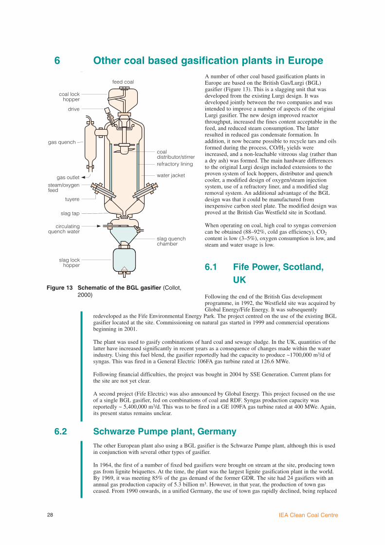
6 Other coal based gasification plants in EuropeA number of other coal based gasification plants inEurope are based on the British Gas/Lurgi (BGL)gasifier (Figure 13). This is a slagging unit that wasdeveloped from the existing Lurgi design. It wasdeveloped jointly between the two companies and wasintended to improve a number of aspects of the originalLurgi gasifier. The new design improved reactorthroughput, increased the fines content acceptable in thefeed, and reduced steam consumption. The latterresulted in reduced gas condensate formation. Inaddition, it now became possible to recycle tars and oilsformed during the process, CO/H2 yields wereincreased, and a non-leachable vitreous slag (rather thana dry ash) was formed. The main hardware differencesto the original Lurgi design included extensions to theproven system of lock hoppers, distributor and quenchcooler, a modified design of oxygen/steam injectionsystem, use of a refractory liner, and a modified slagremoval system. An additional advantage of the BGLdesign was that it could be manufactured frominexpensive carbon steel plate. The modified design wasproved at the British Gas Westfield site in Scotland.
When operating on coal, high coal to syngas conversioncan be obtained (88–92%, cold gas efficiency), CO2content is low (3–5%), oxygen consumption is low, andsteam and water usage is low.
6.1 Fife Power, Scotland,UK
Following the end of the British Gas developmentprogramme, in 1992, the Westfield site was acquired byGlobal Energy/Fife Energy. It was subsequently
redeveloped as the Fife Environmental Energy Park. The project centred on the use of the existing BGLgasifier located at the site. Commissioning on natural gas started in 1999 and commercial operationsbeginning in 2001.
The plant was used to gasify combinations of hard coal and sewage sludge. In the UK, quantities of thelatter have increased significantly in recent years as a consequence of changes made within the waterindustry. Using this fuel blend, the gasifier reportedly had the capacity to produce ~1700,000 m3/d ofsyngas. This was fired in a General Electric 106FA gas turbine rated at 126.6 MWe.
Following financial difficulties, the project was bought in 2004 by SSE Generation. Current plans forthe site are not yet clear.
A second project (Fife Electric) was also announced by Global Energy. This project focused on the useof a single BGL gasifier, fed on combinations of coal and RDF. Syngas production capacity wasreportedly ~ 5,400,000 m3/d. This was to be fired in a GE 109FA gas turbine rated at 400 MWe. Again,its present status remains unclear.
6.2 Schwarze Pumpe plant, GermanyThe other European plant also using a BGL gasifier is the Schwarze Pumpe plant, although this is usedin conjunction with several other types of gasifier.
In 1964, the first of a number of fixed bed gasifiers were brought on stream at the site, producing towngas from lignite briquettes. At the time, the plant was the largest lignite gasification plant in the world.By 1969, it was meeting 85% of the gas demand of the former GDR. The site had 24 gasifiers with anannual gas production capacity of 5.3 billion m3. However, in that year, the production of town gasceased. From 1990 onwards, in a unified Germany, the use of town gas rapidly declined, being replaced
IEA Clean Coal Centre28
steam/oxygenfeed
coaldistributor/stirrer
gas outlet
refractory lining
water jacket
slag quenchchamber
tuyere
slag tap
circulatingquench water
slag lockhopper
gas quench
drive
coal lockhopper
feed coal
Figure 13 Schematic of the BGL gasifier (Collot,2000)

with natural gas. Shortly after, work began to develop a strategy for the large-scale gasification of wasteat the site, and from 1995, investment began in a new methanol plant, a power station, and several fuelpreparation facilities.
In 1997, a new combined cycle power plant and methanol synthesis plant were started up. In principle,both plants represented well proven technologies for conventional fuels and feedstocks, such as naturalgas and oil. However, the use of syngas produced from combinations of coal, wastes and residues formethanol production and IGCC power generation was (and remains) unique. In 2000, a new BGLgasifier was started up. In 2005, the site was taken over by the Swiss-based Sustec Group.
An important concept at the site is the integration of several different types of gasifier, thus enabling awide range of input materials, notably residues and wastes, to be used with local coal. This provides ahigh degree of flexibility in operation. The plant is generally viewed as being more in competition withconventional waste incineration concepts than other power producers. However, unlike incinerationplants, it offers the advantage that organic materials can be broken down during the gasification processwith much lower levels of pollutant emissions. Furthermore, overall efficiency is much higher thanconventional refuse incinerators.
6.2.1 FuelsApart from lignite, a major local energy resource, the plant processes a wide range of waste-derivedfeedstocks. It has the capacity to handle 400 kt/y of solids and 50 kt/y of liquids. Solids gasified withlignite include waste plastics, municipal waste, sewage sludge and shredder residues. Liquids includeoils, tars and waste solvents. These feedstocks are processed to produce a combination of syngas,methanol, gypsum powder and steam.
Depending on the type of waste feedstock, several agglomeration or preparation techniques may beapplied. For instance, waste plastics are extruded, sewage sludge is briquetted, municipal waste andsewage sludge/tar sludge is pelletised, and wood is chipped. Between 1992 and 2005, significantquantities of wastes have been processed. These and their main properties are shown in Table 6.
6.2.2 Gasification technology
Three different types of gasifier are deployed at the plant. These comprise a BGL slagging unit, a GSPentrained flow unit (owned by Sustec’s Future Energy) and a (FDV) Lurgi rotating grate gasifier. Thethree operate in an integrated manner and between them, have processed significant amounts of coal andother materials. The individual gasification systems are examined in the following section.
BGL gasifierThe unit has a diameter of 3.6 m and operates at a temperature of 1600ºC and a pressure of 25 bar. Ithas a throughput of 35 t/h fuel and produces up to 35,000 m3/h of syngas. The gasifier uses 6000 m3 ofoxygen and 6–9 t of steam for each hour of operation. Syngas temperature at the exit of the gasifier is500–700ºC. This is reduced to ~200ºC after scrubbing. Around 7.5 t/h of slag is produced.
The composition of the syngas produced depends on the particular combination of coal and wastesgasified. Thus, plastics may be admixed at a level of 5–50%, tar/sludge pellets at 5–25%, MSW pellets
Coal gasification and IGCC in Europe 29
Table 06 Quantities and types of wastes gasified at Schwarze Pumpe, 1992-2005
Feedstock Quantity,kt
Heating value,MJ/kg
Water, wt%
Ash, wt%
MeOH production,kg/t waste
Waste plastics 900 33.7 1.5 7.8 596
Sewage sludge 120 11 8 43.5 160
Contaminated wood 225 16.8 1 11 357
RDF 295 18 4.5 20 392
Tar/sewage sludge pellets 160 – – – –
Shredder residues 20 11 7.5 43.8 211
Other solids 95 – – – –
Contaminated oils, oil/watermixtures, solvent mixtures 1300 – – – -–

at 5–50%, and wood at 5–15%. Up to 80% waste (with 20% lignite) can be accommodated in thegasifier. Depending on the blend, ash levels can be between 10% and 25%. Up to 36 t/h of feedstockcan be processed, producing 25,000–35,000 m3 syngas/h. Examples of syngas produced are given inTable 7.
After scrubbing the syngas with recycled gas liquor, it is CO shifted to obtain the appropriate H2:COratio prior to feeding to the methanol plant. Gas liquor from gas cooling contains tars and oils from thecarbonisation zone in the gasifier. After separation by gravity, these are recycled for gasification or sentto the entrained flow gasifier for processing.
Despite its successful application to the variousfeedstocks, there are a series of modifications planned inorder to increase the gasifier’s availability. These include(Kamka and others, 2005):l installation of larger coolers of improved design to
overcome clogging of the slag water cooler. Whereslagging of the slag outlet occurs, it is proposed todecrease the heat losses through installation of aSiC cone at the outlet nozzle, to optimise coolingprocedures, and to install equipment to removemetals from the loading belts;
l improvements to increase the life of the nozzlesused to inject the gasification agent throughprovision of a double coating of a suitable wear-resistant material;
l to improve geometry of the outlet of the gasifierfeed hopper and to improve control of thewaste/coal input. At times, depending on thefeedstocks being used, there have been feedingproblems;
l addition of cooling water jets in parts of the uppergasifier sections. This will overcome the formationof coke-like material in the upper section,particularly in the area of the raw gas outlet.
Future Energy GSP entrained flow gasifierThis is similar in concept to a Texaco gasifier in that it is entrained flow and is fired downwards fromthe top and has a quench unit at the base. However, it incorporates a cooling screen rather like a Shellgasifier. The 130 MWth oxygen blown unit was first commissioned in 1984. Ash leaves the reactor inliquid form and slag is handled via a discharge lock hopper and scraper conveyor (Greil and others,2002). This unit was originally installed for the gasification of dry lignite and was modified for theprocessing of liquid feedstocks such as waste oils and slurries. The reactor is equipped with a coolingsystem for operation at temperatures of 1600–1800ºC and pressure of ~25 bar.
The unit now serves as a ‘bottoming’ gasifier, converting hydrocarbon-containing waste streams fromgas processing into syngas and mineral slag. If required, a supplementary fuel such as natural gas canbe added in order to maintain the reaction temperature in the appropriate range. Gas from reactor ispartly shifted prior to purification in a Rectisol unit. It is then sent to the methanol synthesis plant(Future-energy, nd).
(FDV) Lurgi rotating grate gasifierThe FDV process is similar to the Lurgi moving bed coal gasification process. The gasifier has aninternal diameter of 3.6 m and operates in counter current mode, where fuel descends and gasificationagent/gases rise. The gasification agent is a mixture of steam and oxygen. This unit is oxygen blownand operates at 24–25 bar. It is used to convert mixed feedstocks to medium calorific value fuel gas orsyngas. Processing capacity varies between 8 and 14 t/h, depending on the feedstock composition.
As this type of gasifier requires fuel in lump form (~20–80 mm) feeds are sometimes agglomerated bybriquetting, pelletising or some other method prior to feeding.
6.2.3 Balance of plantThe plant comprises a complex of highly integrated systems that prepare and feed various fuels to thesite’s three gasifiers. A variety of gas cleaning facilities help to ensure that low plant emission levels aremaintained.
The site’s combined cycle plant is built around a MS6001B gas turbine provided by Thomassen underlicence from GE. This was suitably modified to operate on syngas. The gas turbine produces 44.5 MWof electricity that is sold into the local grid. Heat from the turbine’s exhaust is captured in a heat
IEA Clean Coal Centre30
Table 07 Syngas produced by the BGL gasifier
Component Operation with highlevel of wastes, vol%
Operation on lignitealone, vol%
H2 18.0 28.0
CO 33.5 56.0
CO2 16.0 2.8
CH4 18.0 6.0
N2 10.0 6.0
O2 0.3 0.1
CnHm ~3.5 0.6
H2S 0.2 0.3
CV (MJ/m3) 15.8 13.0

recovery steam generator that supplies steam to a 30 MWe ABB Turbinen steam turbine and generates240 t/h of process steam for the waste treatment plant. The gas turbine also burns purge gas from themethanol plant. It uses distillate oil as back-up and start-up fuel.
Some of the syngas produced is fed through a shift convertor prior to feeding to the methanol synthesisplant. The CO shift conversion unit was commissioned in 1993 and has a capacity of 80,000 m3/h of dryraw gas. It operates at a temperature of 500ºC and pressure of 25 bar. The catalyst system used is basedon CoO/MoO3. The CO content of the gas after shift is <5% vol%. (Future-energy, nd). Water is addedto the syngas to maintain a carbon:hydrogen ratio of 2:1. The syngas is then reacted by a catalyticprocess to produce crude methanol that is then suitably refined. Annually, the site’s methanol plantproduces ~100 kt of liquid methanol.
6.2.4 Future site developmentsSustec, as the new owner of the site, has announced plans for financial restructuring and extensiveinvestment to the plant. It is intended that this will include the installation of a new coal gasificationfacility based on GSP technology, and an increase in the scale of methanol production (Kamka andothers, 2005).
6.3 Gorazde ammonia plant, BosniaAmmonia production started at the site in 1952, using Low Pressure Winkler gasification technology.The most recent reports suggest that a single Lurgi gasifier, fed on local lignite, is being operated by
Fabrika Azotnih Jendinjenja to produce syngas for ammonia manufacture. Reportedly, ~53 t/d of ligniteis gasified, producing 120,000 m3/d of syngas (gasification.org, 2006). However, the plant wasapparently badly damaged in the mid 1990s during the Balkans conflict and the current level ofcommercial activity remains unclear.
Coal gasification and IGCC in Europe 31

7 European refinery-based IGCC plants
7.1 IntroductionThe demand for petrochemical products continues to increase and is outpacing that of traditional oilproducts. Approximately 12% of the crude oil barrel is now used for petrochemical production.Worldwide demand for petrochemicals has risen from 140 million barrels in 1990 to current levels of~240 million barrels/y. Gasification is being increasingly deployed to meet this rising demand and at thesame time, is allowing refiners to dispose of unwanted by-products in a cost-effective manner. Syngasfrom the gasification of various refinery waste streams is being used increasingly for IGCC applicationsto generate electricity, alongside the production of hydrogen and a range of petrochemical products suchas methanol, dimethyl ether, ammonia and oxy-chemicals (Phillips, 2005).
Major European refinery-based IGCC facilities are examined on a country basis in the followingsection.
7.2 Italy
7.2.1 SARLUX IGCC plant, Cagliari, SardiniaThe SARLUX plant was completed in 2000 and is operated by Saras Raffinerie Sarde. As with manyother European refineries, the IGCC facility was built partially in response to the declining market forheavy oils and the introduction of increasingly stringent emissions legislation.
Three oxygen blown Texaco quench gasifiers are used to gasify residual products (such as visbreakertar) from the refinery processes to produce 100 t/h medium and 85 t/h low pressure steam, and hydrogenfor the SARAS refinery. Oxygen for the gasification process is provided by an ASU supplied by AirLiquide Italia. The three gasifier trains are capable of producing 8,900,000 m3/d syngas, some of whichis also used to generate electricity in the IGCC plant. A proportion of the electricity generated is fedinto the Sardinian grid. Syngas properties are given in Figure 14. The gas has a H2:CO ratio of 0.74 anda CV of 6403 (kJ/m3, LHV). Water is used as diluent.
A total of 548 MWe is produced by the IGCC facility, some of which is sold to ENEL under a 20-year(base load) power purchase agreement (O’Keefe and Kelty, 2004). Syngas is used to power three steamand gas GE STAG 109E combined cycle systems. Each of these has a GE MS9001 gas turbine, a steamturbine, and a generator on the same shaft. The steam turbines are 61 MW axial flow units. Exhaustfrom the gas turbines is fed into an HRSG which produces steam at three pressures. Sulphur isremoved from the system using a Selexol unit. Annually, 50 kt of elemental sulphur is produced.
7.2.2 ISAB Energy, Priolo, SicilyThe refinery, Italy’s second largest, is owned by ERGPetroli and Edisson Mission Energy. The IGCC facilityis operated by ISAB Energy Services and is locatedadjacent to the refinery. As elsewhere, the reasonsbehind the plant’s construction were partially motivatedby decreasing markets for heavy oils, especially thosewith high sulphur content, and changes in emissionslegislation.
The IGCC plants began using syngas in 1998/9 andwere brought into full commercial operation in 2000.Two gasifier trains are deployed, each using an oxygenblown Texaco quench-type gasifier able to gasify 132 t/hof residual asphalt. This is an extremely heavy stockcontaining 6% sulphur and ~1000 ppm Ni, V, and Fe. Itis being supplied under a 20 year deal by ERG Petroli.Prior to gasification, the residue is treated by passingthrough a deasphalter to recover deasphalted oil which isfed back into the refinery. The facility is capable ofproducing up to 7,181,000 m3/d syngas. Oxygen for thegasification process is supplied from an ASU operatedby Air Liquide; this supplies up to 100,000 m3/h of 95%pure O2.
IEA Clean Coal Centre32
N2 + Ar1.1%
H222.7%
CO30.8%
H2O39.8%
CH40.2%
Figure 14 SARLUX syngas properties

The gasification process produces carbon soot whichmixes with the quench water. This is then fed into therecirculating naphtha stream and the resultant slurry fedto a naphtha stripper. The remainder of the soot andasphalt slurry is fed to the gasifiers. The syngasproduced is passed through a heat recovery sectionwhere it produces steam. It is then fed to a COShydrolysis unit, then finally to an acid gas removalsection for H2S removal. The sulphur-free gas is thenhumidified in order to reduce NOx emissions. Thecomposition of the syngas is given in Figure 15.
The clean syngas has an H2:CO ratio of 0.85 and a CVof 9.1 MJ/kg (LHV). It is supplied to the combinedcycle which incorporates two Siemens V94.2K gasturbines, with two HRSGs and two condensation steamturbines. Total electrical output is 512 MWe. Much ofthis is sold to ENEL under terms of a 20-year (baseload) power purchase agreement (O’Keefe and Kelty,2004). Process steam is also produced. By 2003, the gasturbines had operated for a total of 62,000 hours, thevast majority (59,000 hours) on syngas (Hannemann andothers, 2003). Secondary gas turbine fuel is fuel oil.
7.2.3 api Energia S.p.A. IGCC plant, FalconaraThe Falconara refinery is owned by api and has an annual production capacity of ~4 Mt of oil. In 2001,the IGCC plant, which is located within the refinery complex, was brought into operation, processingrefinery residuals such as visbreaker tar containing 6.8–8.6% sulphur and ~240 ppm Vanadium. Themain drivers for the project were similar to those behind other Italian refinery IGCC projects, althoughhere, there was the additional requirement for the substitution of a thermoelectric generating plant oflow efficiency with a more efficient, less polluting form of power generation. The total project cost wasUS$750 million.
The gasification train uses an oxygen blown quench-type Texaco gasifier that produces syngas (of CV7000 kJ/kg, LHV) for two Siemens V94.2 gas turbines modified and supplied by Ansaldo. The gasifierprocesses 59.2 t/h of refinery residues. Syngas production capacity is up to 3,630,000 m3/d.
Oxygen for the gasifier is supplied from a Praxair ASU that produces 62 t/h of oxygen.
Prior to firing in the gas turbines, the cleaned syngas is diluted with nitrogen to reduce NOx formation.The plant has a net electricity output of 282 MW; this is sold to ENEL under terms of a 20 year (baseload) power purchase agreement. The facility also produces 65,000 t/h steam for refinery processrequirements. Medium pressure steam is produced at the rate of 31 t/h, and low pressure steam, 34 t/h.
Up to 4 t/h of elemental sulphur is produced from H2S removed from the process in a Claus unit.
7.2.4 ENI Sannazzaro IGCC plantThis is the newest Italian refinery-based IGCC project and has been built with a view to finding anapplication for unwanted refinery wastes and need for more electricity in the country. Thus, a new ENIcombined cycle plant of 1050 MWe fed by both natural gas and syngas has been constructed. Hydrogenand steam are also produced for refinery use.
The plant uses two Shell gasifiers, each of 600 t/d capacity, to gasify feedstocks that include bitumen,surplus heavy fuel oil, and visbreaker tar. In the case of the latter, each train uses a reciprocating feedpump to feed the tar to the gasifier. The gasifiers operate at 62 bar pressure and have been equippedwith specially designed co-annular burners; this design provides efficient gas/liquid mixing and goodflame temperature control. Oxygen (99.5% pure) for the gasification process is preheated with saturatedsteam from the syngas cooler and mixed with superheated steam as moderator, prior to feeding to theburner. The syngas temperature when entering the syngas cooler is ~1300ºC.
Syngas not used within the refinery is sold to the IGCC plant; this is operated by a separate company.Electricity is produced by two 400 MW Ansaldo-Siemens V94-3A.2, and one 250 MW V94-2K gasturbines.
In July 2003, the first gas turbine was connected to the Italian power grid. During the first half of 2004,the combined cycle unit was started up using natural gas, and during the latter part of 2005, gasificationplant operations began (Collodi and Brkic, 2003).
Coal gasification and IGCC in Europe 33
H231.3%
CO28.5%
H2O36.9%
CO23.2%
Figure 15 Composition of ISAB syngas (Hannemannand others, 2003)

7.3 The Netherlands – Pernis RefineryThe Shell Pernis refinery is one of the largest industrialcomplexes in The Netherlands. It has a processingcapacity of ~18 Mt/y. The site employs three parallelgasification trains with a capacity of 1650 t/d residue(either vacuum flashed cracked residue from the thermalcracking unit, or a mixture of visbreaker tar, vacuumresidue and propane asphalt). The capacity of thegasification trains is such that any two can produce thehydrogen required by the hydrocracker, the maximumbeing 285 t/d. Each train comprises an oxygen blownShell gasifier, feed pumps, a reactor-effluent boilercombination, boiler feedwater preheater, and sootquenching and scrubbing facilities. Oxygen for thegasification process is produced in an ASU (99.5% pure,at 70 bar pressure) owned and operated by Air Products.
The raw gas from the gasifiers is cooled to below 400ºCand the heat recovered used to produce high pressuresteam (~95 bar). After the boiler, the gas passes throughan economiser where boiler feed water is heated from140ºC to 200ºC. The gas then passes through a sootquench stage, followed by a cooler and scrubber. Thegasifiers can generate up to 4,662,200 m3/d of syngasfor hydrogen production and IGCC power generation(de Graaf, 2002). Syngas composition is given inFigure 16. The gas has a CV of 8274 kJ/m3 (LHV) andan H2:CO ratio of 0.98. Steam is used as diluent.
The site’s IGCC plant, completed in 1997, generates142 MW (gross) of electricity and comprises two gas
turbines (GE Frame 6) and two steam turbine generators that burn clean syngas not required forhydrogen production. Steam for the steam turbines is produced in the heat recovery boilers of thegasification unit. Sulphur is removed from the raw syngas produced by means of the Lurgi Rectisolprocess. This unit integrates sulphur removal with CO2 removal downstream from the CO shift section.Excess syngas for the gas turbines is taken off as a side stream (Zuideveld and others, 1998).
7.4 Poland – Grupa Lotos S.A. (LOTOS) refinery, GdanskThe refinery is the second largest in Poland, with a processing capacity of 4.5 Mt/y of crude oil. Anumber of measures are being taken to update the complex and improve its economic andenvironmental performance. The IGCC project began in 2002 when LOTOS Ekoenergia wasestablished. Its main goal was the construction of the plant in readiness for legislative andadministrative changes prohibiting the sale of bunker oil with a high sulphur content.
A new Shell gasification unit is being added to the refinery in order to provide hydrogen for thehydrocracker and syngas for the IGCC facility. This will incorporate two oxygen blown Shell gasifiers,two gas turbines, and two steam turbine generators that will utilise the syngas not required for hydrogenproduction and the steam generated by the gasification waste heat boilers. The gasifiers will be capableof producing 3,630,000 m3/d of syngas produced from refinery residuals. The asphaltene stream fromthe desphalting unit will be fed to parallel gasification trains with a total input capacity of 68 t/h. Rawsyngas will be produced from the gasifiers at a temperature of 1300ºC and pressure of 65 bar. This willthen be cooled to below 400ºC in a syngas effluent cooler and the heat recovered to produce HP steamat ~95 bar. The gas will then be passed through an economiser prior to the scrubbing stage. A Rectisoldesulphurisation unit will remove COS and HCN. H2S removed from the syngas will be processed inthe refinery’s Claus and tail-gas treatment plant to produce elemental sulphur (Sep and Wolff, 2004).
Construction work is expected to begin mid 2006. Total plant investment is likely to be ~US$540million.
7.5 France – Confreville refineryAn IGCC plant is being built at the TotalFina/Elf/EdF/Texaco refinery near Confreville in Normandy.
The project started in 1998 with agreement between the partners for a feasibility study for a
IEA Clean Coal Centre34
N2 + Ar0.2%
H234.4%
CO35.1%
CH40.3%
CO230%
Figure 16 Pernis syngas composition

gasification-based cogeneration plant. EdF, TotalFinaElf and Texaco respectively hold interests of 50%,25% and 25% of the facility. Estimated project costs are €230 million.
The first stage of the project has focussed on the installation of a natural gas fired combined cyclecogeneration plant, producing steam and power for initial operations. The second phase of the projectwill see the installation of the gasification unit. This will use Texaco gasification technology to gasifyrefinery heavy oil bottoms. Three parallel gasification trains based on Texaco quench-type gasifiers willbe used, capable of producing up to 7,600,000 m3/d of syngas.
Once fully operational, the cogeneration facility will operate continuously and produce 375 t/h steamand 365 MW (net) of electricity, to be supplied to Edf, the refinery, and the neighbouring petrochemicalcomplex operated by AtoFina (a subsidiary of Total FinaElf). EdF are responsible for the engineeringand construction and will market the plant’s electricity output. The plant will also produce 250 t/h steamand 50–150 t/d of hydrogen. Original planned plant start-up was 2005.
7.6 Germany – Leuna Methanolanlage (MIDER), GermanyThis large refinery was built by Lurgi and is owned and operated by Total. It has an annual processingcapacity of ~5–6 Mt/y crude oil and produces up to 225,000 b/d of various products. Present operationsbegan in 1985.
Part of the refinery comprises a methanol production plant with a capacity of 550,000 t/y. This issupplied with syngas produced by six Shell gasifiers that gasify visbreaker residues. The gasifiers havethe capacity for producing up to 7,200,000 m3/d of syngas. This is used to feed the methanol plant andgenerate electricity from an on-site IGCC facility. Elf takes methanol from the methanol productionplant and uses it for the manufacture of formaldehyde and adhesives.
7.7 Spain – Petronor refineryA few years ago, proposals were made for an 800 MWe IGCC plant at the Petronor refinery in NorthernSpain. Visbeaker tar (195 t/h) was to be gasified in two parallel gasification trains and used to producehydrogen and syngas for combustion in two 294 MWe gas turbines. Texaco quench-type gasifiers wereproposed. A steam turbine was to produce a further 347 MWe, giving an overall gross output of935 MWe. However, it appears that the project may now have been cancelled although there is thepossibility that it could be revived in the future.
Coal gasification and IGCC in Europe 35

8 ReferencesAineto M, Acosta A, Rincon J M, Romero M (2005) Production of lightweight aggregates from coalgasification fly ash and slag (Puertollano). At: http://www.flyash.info/2005/7ain.pdfAqua-chem (nd) Demkolec ICGCC power plant. Evaporator/crytallizer meets stringent zero-dischargewaste requirements. At: http://www.aquatech.com/pdf/3.pdfBucko Z (2000) HTW fluidized-bed gasification for 400 MW IGCC power plant, Vresova - CzechRepublic, Gasification Technologies Conference, San Francisco, USA, 9-11 October (2000)Buryan P, Vejvoda J (1999) Electricity production by way of coal gasification in Vresova plant, 3rd
international conference on catalysis and adsorption in fuel processing and environmental protection,Kudowa Zdroj, Poland, 15-18 September (1999)Capilla A V (2005) MONEFE project - monitoring and optimization of the main equipment efficiency ofthe IGCC- Puertollano. At: http://teide.cps.unizar.esCoca M T, Mendez-Vigo I, Elias F A (nd) Coal gasification, conception, implementation andoperation of the Elcogas IGCC power plant. At: http://www.worldenergy.orgCoca M T (2003) Integrated gasification combined cycle technology: IGCC, Its actual application inSpain: ELCOGAS, Puertollano. Presentation made to Club Espanol de la Energia.At: http://www.elcogas.com/ (2003)Collodi G, Brkic D (2003) The experience of Snamprogetti’s four gasification projects for over 3000MWth, Gasification technologies conference 2003, San Francisco, USA, 12-15 October (2003)Collot A-G (2002) Matching gasifiers to coals. CCC/65. London, UK, IEA Clean Coal Centre, 64pp(October 2002)Chhoa T (2005) Shell gasification business in action. Presentation made October 2005.At: http://www.gasification.org/Docs/2005_Papers/05CHHO.pdf (2005)DTI (2005) UK Cleaner Coal Technologies in Central and Eastern Europe, Assessment of marketopportunities, Project Report R270, DTI/Pub URN 05/678, March (2005) Elcogas (nd) IGCC Puertollano. A clean coal gasification power plant.At: http://www.elcogas.com/shared/thermie.pdfFont O, Querol X, Plana F, Lopez-Soler A, Chimenos J M, March M J, Espiell F, Burgos S,Garcia Pena F, Alliman C (2001) Occurrence and distribution of valuable metals in fly ash fromPuertollano IGCC power plant, Spain. 2001 International ash utilization symposium, Center for AppliedEnergy Research, University of Kentucky, USA. Paper #98. At: http://www.flyash.infoFuture-energy (nd) Future Energy GmbH, Entrained flow gasifier (Spalter IV).At: http://www.future-energy.de/references.htmlGarcia-Pena F, Munoz-Mozos A (2002) MBM (Meat and Bone Meal) co-gasification in IGCCtechnology, ASME Turbo Expo 2002, Amsterdam, The Netherlands, 3-6 June (2002)Gasification.org (2006) Key gasifier information, Vresova town gas plant. At:http://www.gasification.org/resource/database/gasifier.aspx?GasID=274 (2006)Global Energy (2006) Environmental energy technology company. At:http://www.globalenergyinc.com/ (2006)de Graaf J (2002) Overview of Shell Global Solutions’ worldwide gasification developments,Gasification Technologies Conference, San Francisco, USA, October 27-30 (2002)Greil C, Hirschfelder H, Turna O, Obermeier T (2002) Operational results from gasification of wastematerial and biomass in fixed bed and circulating fluidised bed gasifiers, 5th European IChemEgasification conference, Noordwijk, The Netherlands, 9th April (2002)Hannemann F, Schiffers U, Karg J, Kanaar M (2002) V94.2 Buggenum experience and improvedconcepts for syngas applications, Gasification Technologies Conference, San Francisco, USA, October27-30 (2002)Hannemann F, Koestlin B, Zimmermann G, Morehead H, Pena F G (2003) Pushing forward IGCCtechnology at Siemens, Gasification Technologies Conference, San Francisco, USA, 13-15 October(2003)HeidenreichS, Wolters C (2004) Hot gas filter contributes to IGCC power plant’s reliable operation.Filtration + Separation, June 2004. At: http://www.filtsep.com/Henderson C (2003) Clean coal technologies. CCC/74. London, UK, IEA Clean Coal Centre, 42pp(October 2003)Holt H (2004) Coal-based IGCC plants. Recent operating experience and lessons learned, GasificationTechnologies Conference, Washington DC, USA, 4-6 October (2004)Jansen P (2002) Large scale production of biofuels through biomass (co-) gasification and Fischer-Tropsch synthesis, TNO Environment, Energy and Process Innovation, Apeldoorn, The Netherlands,Report R2002/406, August (2002)Jansen P (2004) Innovative biofuel production processes: Fischer-Tropsch synthesis and hydro thermalupgrading, EU- China workshop on liquid biofuels, Beijing, China, 4-5 November (2004)Kanaar M (2005) Power plant concepts and thermodynamics, VGB PowerTech, 9th meeting of theworking panel, 16 November (2005)Kanaar M (2006) Nuon, The Netherlands, personal communication. 17 February (2006)Kamka F, Jochmann A, Picard L (2005) Development status of BGL-Gasification [at SVZ SchwarzePumpe plant], International Freiberg Conference on IGCC and XtL Technologies, Freiberg, Germany,
IEA Clean Coal Centre36

16-18 June (2005)Masaki T (2000) The World Bank Group’s activities on CCT and ZETS, IEA Zero EmissionTechnologies, Washington DC, USA, 19 March (2002)Materials and Components (2002) Design aspects of major coal-based IGCC projects. Materials &Components, No. 157; 1st April (2002)Mendez-Vigo I (2002) Gasification operations and performance update, Elcogas Puertollano IGCCupdate, Gasification Technologies Conference, San Francisco, USA, October 27-30 (2002)Mika P (2005) Use of liquid by-products of pressure gasworks in Vresova, International FreibergConference on IGCC and XtL Technologies, Freiberg, Germany, 16-18 June (2005)Navarette B, Lupion M, Gutierrez F J, Cortes V J, Coca P, Garcia Pena F (2005) Improving thePuertollano IGCC dedusting system; pilot plant erection and testing, International Freiberg Conferenceon IGCC and XtL Technologies, Freiberg, Germany, 16-18 June (2005).Nuon (2005) Nuon develops new large power station. Nuon press release, 29 September (2005).At: http://corporate.nuon.com/ (2005)O’Keefe L F, Kelty F J (2004) Exploring project finance options. Building on European IGCCexperience. Workshop on gasification technologies, Indianapolis, IN, USA, 8-9 June (2004)Pena F G (2005) Operating experience and current status of Puertollano IGCC power plant,International Freiberg Conference on IGCC and XtL Technologies, Freiberg, Germany, 16-18 June(2005)Phillips G (2005) Gasification - a versatile solution for clean power, fuels and petrochemicals and anopportunity to reduce CO2 emissions, 7th World Congress of Chemical Engineering, Glasgow, UK, 10-14 July (2005)Rosenberg W G, Dwight C A, Walker M R (2004) Deploying IGCC in this decade with 3Partycovenant financing, Harvard University, USA, John F Kennedy School of Government. Volume II, July(2004)Rousaki K, Couch G R (2000) Advanced clean coal technologies and low value coals. CCC/39,London, UK, IEA Clean Coal Centre, 76 pp (November 2000)Sep K, Wolff J (2004) Residue upgrading with the Shell gasification process for LOTOS refineryGdansk, Gasification Technologies Conference, Washington, USA, 2-5 October (2004)SESEM (2005) SESEM CFT project, Demonstration support needs for large scale clean fossil fuel inthe 7th FP. ELCOGAS contribution, IX EU Cleaner fossil technology industry forum, Brussels, Belgium,14 March (2005)Scheibner B, Wolters C (2002) Schumacher hot gas filter long-term operating experience in the NuonPower Buggenum IGCC power plant.At: http://www.netl.doe.gov/publications/proceedings/02/GasCleaning/1.05paper.pdf (2002)Simbeck D (2005) SFA Pacific’s insights and overviews of lignite gasifiction, The New Zealand LigniteSymposium, Invercargill, New Zealand, 10 March (2005)Wolters C, Kanaar M (2005) Update of Nuon Power Buggenum plant performance and fuel flexibility,Clean Coal Technologies 2005 Conference, Sardinia, Italy, 10-12 May (2005)Zuideveld P L, de Graaf J D, Posthuma S A (1998) Initial operation of the Shell Pernis residuegasification project, Gasification Technologies Conference, San Francisco, USA, 4-6 October (1998)Zuideveld P (2006) Shell, The Netherlands. Personal communication. 31 January (2006)
Coal gasification and IGCC in Europe 37