coal mine robot (project report)
TRANSCRIPT

BACHELOR OF ELECTRICAL AND ELECTRONIC ENGINEERING UNIVERSITY OF BRADFORD
1 COAL MINING ROBOT, 2013
MUHSIN ABDUL MOHAMMED
UNIVERSITY OF BRADFORD PROGRAMME
INTI International University
Faculty of Engineering and Information Technology
COAL MINE ROBOT
Muhsin Abdul Mohammed
Bachelor of Engineering (Hons) in ELECTRICAL &
ELECTRONICS ENGINEERING
Project Supervisor: Mr. Jeya Gopi
Stage 3 BEng Project
2013

BACHELOR OF ELECTRICAL AND ELECTRONIC ENGINEERING UNIVERSITY OF BRADFORD
2 COAL MINING ROBOT, 2013
MUHSIN ABDUL MOHAMMED
Abstract
This project tackles the problem of coal mine accidents which results in the death of several
people per year. It is found out that the rate of fatality in the coal mine industry is nearly six
times the rate for all private industry. And most of these accidents are due to toxic gasses,
fires and lack of rescue system.
By implementing a Coal Mine Surveillance robot, which can move around unmanned in the
mine and detect the level of different toxic gases and temperature level and report them live
to the control room, this level of fatality can be considerable reduced. The objective of this
project is to accomplish this task.
From a technical aspect this project is software and hardware oriented project. It requires
very specific types of sensors, and innovative methods in transmitting and receiving data.
Because a conventional approach will not do much good from an industrial aspect
The project can be considered valid if it can detect different sorts of gases, the temperature
and give a warning to the miners inside the mine in case of a danger, at the same time
transmitting all the data to the control panel. The data send to the control panel can make a lot
of difference, setting up and giving strategies to a rescue team for rescue will make the rescue
very efficient.
i

BACHELOR OF ELECTRICAL AND ELECTRONIC ENGINEERING UNIVERSITY OF BRADFORD
3 COAL MINING ROBOT, 2013
MUHSIN ABDUL MOHAMMED
ACKNOWLEDGEMENT
I would like to take this opportunity to express my gratitude to all the people who assisted me
during the development of this project. I would like to express my appreciation to my
supervisor, Mr.Jeya Gopi, who guided me through this project and provided me with tasks
and challenges for further understanding of the project.
I would also like to express my thankfulness to my family who gave the moral and financial
support for realizing this project. I am also grateful to my friends, who provide their support
and resources in solving this project. At last, I would like to thank my lectures, the lab and
the faculty staff for giving their time and support to achieve this task.
ii

BACHELOR OF ELECTRICAL AND ELECTRONIC ENGINEERING UNIVERSITY OF BRADFORD
4 COAL MINING ROBOT, 2013
MUHSIN ABDUL MOHAMMED
Declaration
I submit my University of Bradford, Bachelor in Electrical and Electronic Engineering, Final
Year Project, under the supervision of Mr.Jaya Gopi. I hereby certify that no part of this
Project has been copied, except where due acknowledgement is made.
Yours truly,
.
Muhsin Abdul Mohammed
INTI-UC ID: I10005723
UOB ID: 10040883
iii

BACHELOR OF ELECTRICAL AND ELECTRONIC ENGINEERING UNIVERSITY OF BRADFORD
5 COAL MINING ROBOT, 2013
MUHSIN ABDUL MOHAMMED
List of Acronyms
PWM – Pulse Width Modulation
PCB – Printed circuit board
MCU – Microcontroller unit
IDE - Integrated Development Environment
IC – Integrated Circuit
iv

BACHELOR OF ELECTRICAL AND ELECTRONIC ENGINEERING UNIVERSITY OF BRADFORD
6 COAL MINING ROBOT, 2013
MUHSIN ABDUL MOHAMMED
Table of Contents
Abstract – i
Acknowledgement –ii
Declaration –iii
List of Acronym – iv
Table of contents - v
Chapter 1: Introduction -------------------------------------------------------------------------------1
1.1 Background ----------------------------------------------------------------------------------1
1.1.1 History of Tools in Mining Safety-------------------------------------------1
1.2 Nature and Purpose of Study --------------------------------------------------------------2
1.3 Significance of this project ----------------------------------------------------------------3
1.4 Objectives ------------------------------------------------------------------------------------3
1.5 System Overview ---------------------------------------------------------------------------3
1.6 Project Overview ---------------------------------------------------------------------------4
Chapter 2: Literature Reviews -----------------------------------------------------------------------6
2.1 Introduction ----------------------------------------------------------------------------------6
2.2 Research in the, Field Mining Robots ----------------------------------------------------7
2.3 Autonomous Robot -------------------------------------------------------------------------8
2.4 Need for this study --------------------------------------------------------------------------9
2.5 Gas Sensors ----------------------------------------------------------------------------------9
2.5.1 Gas Detector Technologies ---------------------------------------------------10
2.5.1.1 Measurement of Toxic Gases -------------------------------------10
2.5.1.2 Measurement of Combustible Gases -----------------------------10
2.5.2 Recent development -----------------------------------------------------------11
2.5.3 Semiconductor Type Gas Sensors -------------------------------------------12
2.6 Temperature Sensor -----------------------------------------------------------------------13
2.7 Communication ----------------------------------------------------------------------------13

BACHELOR OF ELECTRICAL AND ELECTRONIC ENGINEERING UNIVERSITY OF BRADFORD
7 COAL MINING ROBOT, 2013
MUHSIN ABDUL MOHAMMED
Chapter 3: Methodology -----------------------------------------------------------------------------15
3.1 Robot Locomotion ------------------------------------------------------------------------15
3.1.1 Differential Drive --------------------------------------------------------------18
3.1.2 Motor ----------------------------------------------------------------------------19
3.1.3 Drivers ---------------------------------------------------------------------------21
3.2 Atmel Atmega328P -----------------------------------------------------------------------25
3.3 Arduino UNO ------------------------------------------------------------------------------26
3.3.1 Arduino IDE --------------------------------------------------------------------27
3.4 Sensors --------------------------------------------------------------------------------------28
3.4.1 Toxic Gas Sensors -------------------------------------------------------------29
3.4.1.1 MQ Gas sensor Series ----------------------------------------------29
3.4.1.2 Calibration and Coding for Gas sensors -------------------------30
3.4.2 Temperature Sensor ------------------------------------------------------------32
3.4.3 Ultrasonic Ranging Module HC- SR04 -------------------------------------33
3.5 Communication ----------------------------------------------------------------------------37
3.5.1 BlueBee--------------------------------------------------------------------------38
3.6 Software Overview ------------------------------------------------------------------------40
3.7 Graphical User Interface -----------------------------------------------------------------42
Chapter 4: Test and Results -------------------------------------------------------------------------43
4.1 Mechanical Design ------------------------------------------------------------------------43
4.2 Independence of the Robot ---------------------------------------------------------------43
4.3 Working of the sensor --------------------------------------------------------------------44
4.4 Reception of Wireless Data --------------------------------------------------------------45
4.5 Graphical User Interface (GUI) ---------------------------------------------------------49
Chapter 5: Discussion -------------------------------------------------------------------------------50
5.1 Investigation -------------------------------------------------------------------------------50
5.2 Validity of the prototype -----------------------------------------------------------------50
Chapter 6: Conclusion -------------------------------------------------------------------------------51

BACHELOR OF ELECTRICAL AND ELECTRONIC ENGINEERING UNIVERSITY OF BRADFORD
8 COAL MINING ROBOT, 2013
MUHSIN ABDUL MOHAMMED
Chapter 7: Further improvement ------------------------------------------------------------------53
References -----------------------------------------------------------------------------------------------54
Appendix A: Coding for the Microcontroller -------------------------------------------------------55
Appendix B: Processing Sketch for GUI Graph ----------------------------------------------------60
Appendix C: PCB and Schematics -------------------------------------------------------------------63
Appendix D: Pictures taken during the progress of project ---------------------------------------66
PROJECT GANTT CHART -----------------------------------------------------------------------68
LIST OF FIGURE
Figure 1.1 Safety Lamp Principle Features -----------------------------------------------------------2
Figure 1.2 System Overview Block Diagrams -------------------------------------------------------4
Figure 2.1 Total World Electricity Generations by Fuel (2009) -----------------------------------6
Figure 2.2 Modern Automated Coal Mining Processes ---------------------------------------------8
Figure 2.3 an Autonomous Komatsu Truck ----------------------------------------------------------8
Figure 2.4: M40.M precision Gas sensor for coal mines ------------------------------------------11
Figure 2.5: Basic gas sensor structure ----------------------------------------------------------------12
Figure3.1: Simplified Robot locomotion ------------------------------------------------------------16
Figure 3.2: Different types of wheel based robot Chassis -----------------------------------------16
Figure 3.3: Initial stage robot design -----------------------------------------------------------------17
Figure 3.4: Differential Drive System ----------------------------------------------------------------18
Figure 3.5: DC motor working principle ------------------------------------------------------------20
Figure 3.6: Dimension of the DC motor used -------------------------------------------------------21
Figure 3.7: Basic H-Bridge Schematics --------------------------------------------------------------21
Figure 3.8: Block Diagram of L293D IC ------------------------------------------------------------22

BACHELOR OF ELECTRICAL AND ELECTRONIC ENGINEERING UNIVERSITY OF BRADFORD
9 COAL MINING ROBOT, 2013
MUHSIN ABDUL MOHAMMED
Figure 3.9: In-project Implementation of L293D IC -----------------------------------------------23
Figure 3.10: ATmega328P pin mapping -------------------------------------------------------------25
Figure 3.11: Serial communication between MCU and Computer -------------------------------26
Figure 3.12: An official Arduino Uno with descriptions of the I/O locations ------------------27
Figure 3.13: Arduino code editor ---------------------------------------------------------------------28
Figure 3.14: Building Block and recommended circuit connection. -----------------------------30
Figure 3.15: LM35 Pin Values ------------------------------------------------------------------------32
Figure 3.16: HC-SRO4 module Schematic and its range of sight --------------------------------34
Figure 3.17: Timing diagram --------------------------------------------------------------------------34
Figure 3.18: BlueBee Module -------------------------------------------------------------------------38
Figure 3.19: PuTTY window --------------------------------------------------------------------------39
Figure 4.1: Set up for the Obstacle Test -------------------------------------------------------------43
Figure 4.2: Result obtained using UART-USB cable ----------------------------------------------46
Figure 4.3: Results obtained from the sensors using BlueBee. -----------------------------------47
Figure 4.4: Screenshot of the reading received on an Android Mobile --------------------------48
Figure 4.5: Screenshot from Processing -------------------------------------------------------------49

BACHELOR OF ELECTRICAL AND ELECTRONIC ENGINEERING UNIVERSITY OF BRADFORD
10 COAL MINING ROBOT, 2013
MUHSIN ABDUL MOHAMMED
LIST OF TABLES
Table 1.1: Objectives ------------------------------------------------------------------------------------3
Table 2.1 Rules for a Robot to be Autonomous -----------------------------------------------------9
Table 3.1: Design and Implementation Stages ------------------------------------------------------15
Table 3.2: MQ gas sensors -----------------------------------------------------------------------------29
Table 3.3: Most common wireless communication antennas -------------------------------------37
Table 4.1: Results from sensor and real measurement ---------------------------------------------44
Table 6.1: Objectives and status of accomplishment -----------------------------------------------52

BACHELOR OF ELECTRICAL AND ELECTRONIC ENGINEERING UNIVERSITY OF BRADFORD
11 COAL MINING ROBOT, 2013
MUHSIN ABDUL MOHAMMED
CHAPTER 1: INTRODUCTION
1.1 Background
Most coal contents are too deep underground for opencast mining and require
underground mining, a method that currently accounts for about 60% of world coal
production. But Thousands of miners die from mining accidents each year. A Coal
Mine Surveillance Robot is an autonomous mechanical agent which can travel
through an underground mine in conditions that might be unsafe for miners to pass
through. It can collect important data from the mine like the percentage of
combustible gases, temperature in the mine and it can transmit all this data wirelessly
in real time. It can also give the miners a warning when the conditions of the mine are
unsafe.
1.1.1 History of Tools in Mining Safety
Most of the coal mine accidents are caused due to the eruption of toxic and
combustible gas. Before the advancement in the technology and invention of modern
toxic gas detectors, the miners used to relay on devices like Safety lamp and Pellistor.
A safety lamp was a device used in underground coal mines for the purpose of
lighting and to detect the presence of firedamp or methane. The invention of this
device was in the late 18th century, a demand arose in England for a miner’s lamp
that would not ignite the gas methane, a common hazard of English coal mines.
An Irish physician W. Reid Clanny, invented a lamp in 1813, in which using a layer
of water seal was use to separate the oil-fuelled flame from the atmosphere. It
required constant pumping for operation. In 1815 the English engineer George
Stephenson invented a lamp that kept explosive gases out by pressure of the flame’s
exhaust and held the flame in by drawing in air at high speed. In 1815 Sir Humphry
Davy invented the lamp that bears his name. Sir Davy used double layer metal gauze
chimney in order to surround and restrain the flame also to conduct the heat of the
flame away. This device was used for a very long period of time because of its
efficiency (Britannica, 2013).
Miners could detect if there is a presence of methane in the mine by looking in the
safety lamp, the flame of the safety lamp elongates to show this (Britannica, 2013).

BACHELOR OF ELECTRICAL AND ELECTRONIC ENGINEERING UNIVERSITY OF BRADFORD
12 COAL MINING ROBOT, 2013
MUHSIN ABDUL MOHAMMED
But this meant that there should be someone constantly looking after the lamp, and as
the lamp had internal fuel supply it was sometimes not very accurate. But modern gas
detectors can sense the toxic and combustible gases in PPM (Parts per Million), also a
warning can be issued for the miners and the rescue team.
Figure 1.1 Safety Lamp Principle Features
1.2 Nature and Purpose of Study
As mentioned in the beginning of this chapter, the call for mine safety has been in
demand for a very long time; there has been a lot of development in the field of
surveillance robots and safety equipment. Yet the accidents are still occurring and lot of
lives are lost every year. In this project the emphasis is on developing a robot that will be
low cost in terms of mass production and also compatible with the existing technologies.
To succeed in this attempt, the project is designed using an Atmega328p microcontroller
which is a low power, long lasting, and fast in terms of processing. For communication
purposes Bluetooth is used, which is designed in such a way that any computer or
smartphone which has a Bluetooth receptor can receive the data transmitted from the
robot. The gas sensors and temperature sensors used are also efficient in terms of value
and performance, the features of the hardware and software will be discussed in detail in
the third chapter (Methodology).

BACHELOR OF ELECTRICAL AND ELECTRONIC ENGINEERING UNIVERSITY OF BRADFORD
13 COAL MINING ROBOT, 2013
MUHSIN ABDUL MOHAMMED
1.3 Significance of this project
The central idea of this project is to build a surveillance robot which is economically,
technically and operationally feasible. I.e. the robot requires minimal maintenance and as
the robot is autonomous it does not require any operator. It can also send data to any
computer and smartphone because Bluetooth is used for communication. The robot uses
two motors to drive a caterpillar track which by design is focused on torque rather than
rpm, so it can cover more harsh terrain.
1.4 Objectives
Table-1 exhibits the objectives to be met by this project.
Number Objectives
1 Detect the toxic gases emitted from the coal mine.
2 Detect the level of heat inside the coal mine.
3 Indicate the name and the value of the gases and the temperature inside the coal mine regularly to the control room.
4 If level of the gases or temperature is too high a voice warning signal must be activated inside the coal mine.
Table 1.1: Objectives
1.5 System Overview
The active components involved in the project are illustrated in the block diagram Figure 1.
From it we can see that the core of this project is the Atmega328p microcontroller, the
Bluetooth transmitter and the Gas temperature sensors. The reasons why it is said that these
components are core because it serves the active purposes of this project. The circuit design
of the whole project was done fragmentally, namely the Inputs, the autonomous locomotive
and the wireless transmitter. This means that the failing of any one of these tasks will not
directly affect the other tasks; more on this feature will be discussed in the chapter 5
discussion.

BACHELOR OF ELECTRICAL AND ELECTRONIC ENGINEERING UNIVERSITY OF BRADFORD
14 COAL MINING ROBOT, 2013
MUHSIN ABDUL MOHAMMED
Figure 1.2 System Overview Block Diagram
1.6 Project Overview
The duration allowed by the University of Bradford to complete the project was 27 weeks.
During which period the essence and objectives of the project title had to be recognized, the
tactics, tools and methods of doing the project had to be gathered, the project had to be build
and finally it should be made presentable. During the first semester different ways of tackling
the problems where researched, together with the current developments in the field of
surveillance robots. Later different programming environments where studied, namely C,
C++, Arduino programming environment, Processing (based on java) and VB. The second
INPUTS Sensors: mq9 gas sensor, mq4 gas
sensor, temperature
sensor (LM35)
16MHz Crystal Oscillator
9-12V DC Power
Supply
7805 voltage regulator
Bluetooth 2.4 ~
2.48GHz
Computer/
Smartphone*
*Bluetooth
capable
OUTPUT/actuators: 2 DC motors.
H-Bridge IC
OUTPUT: Buzzer, LED.

BACHELOR OF ELECTRICAL AND ELECTRONIC ENGINEERING UNIVERSITY OF BRADFORD
15 COAL MINING ROBOT, 2013
MUHSIN ABDUL MOHAMMED
semester was more focused on implementation of circuits, testing sensors and designing
PCBs. The whole project report is broken down into 7 chapters. They are as follow:
Chapter 1: Introduction
In this section the overview of the whole project is included with the purpose of this
project. The aims and objectives of the project are mentioned. This section also gives the
reader a structure of the project report.
Chapter 2: Literature Reviews
The literature review has covered some of the recent works and researches in the field of
surveillance robots, Gas sensors, Temperature sensors, and proximity sensors.
Chapter 3: Methodology
In this chapter the physical design of the project is explained. It includes a discussion of
the hardware and software parts of the project. In the hardware section the reason of
selection, design, cost-effectiveness and other merits will be discussed. The software
section will include the algorithms (pseudo-code), flow charts and interface design.
Chapter 4: Test and Results
This section includes the final outcome from various aspects of this project, namely how
autonomous the robot is, accuracy of the sensors and data presentation. It also includes
some troubleshooting.
Chapter 5: Discussion
This chapter includes the discussion on the stability and validity of the project, and its
limitations.
Chapter 6: Conclusion
In this chapter all the key points of this project report will be reviewed. It will also
include an account of the final accomplishments from this project.
Chapter 7: Further improvement

BACHELOR OF ELECTRICAL AND ELECTRONIC ENGINEERING UNIVERSITY OF BRADFORD
16 COAL MINING ROBOT, 2013
MUHSIN ABDUL MOHAMMED
This chapter includes some perception on the enhancement of the coal mining
surveillance robot from a prototype to a producible machine. This chapter takes heed
from the limitations discussed in chapter 5 to produce some ideas for future
improvements.
CHAPTER 2: Literature Reviews
2.1 Introduction
Coal is a combustible, sedimentary, organic rock, which is composed mainly of carbon,
hydrogen and oxygen. It is formed from vegetation, which has been fused between other rock
layers and altered by the combined effects of heat and pressure over millions of years to form
coal beds. Coal is a fossil fuel and is far more abundant than oil or gas, with around 112 years
of coal remaining worldwide (Anon, 2011).
Coal has many important uses worldwide. The most significant uses of coal are in electricity
generation, steel production, cement manufacturing and as a liquid fuel.
Since 2000, global coal consumption has grown faster than any other fuel. The five largest
coal users - China, USA, India, Russia and Japan - account for 76% of total global coal use
(Anon, 2011).

BACHELOR OF ELECTRICAL AND ELECTRONIC ENGINEERING UNIVERSITY OF BRADFORD
17 COAL MINING ROBOT, 2013
MUHSIN ABDUL MOHAMMED
Figure 2.1 Total World Electricity Generations by Fuel (2009)
Surveys conducted on energy consumption (Anon, 2012) have shown that more than 40% of
the electricity worldwide is generated from coal.
Most coal contents are too deep underground for opencast mining and require underground
mining, a method that currently accounts for about 60% of world coal production. But
Thousands of miners die from mining accidents each year. This calls for the development of
an autonomous system (robot) which can survey the mines ahead of time and make sure that
the environment is safe for the miners to enter And also during the mining the robot can stay
in the mine and give live feedback to the control room in case of an accident (gas leak or fire)
so that the rescue team can be immediately organised.
Flammable gases are produced in the coal mines due to the oxidation of coal in the sealed off
areas. Monitoring of these toxic and flammable gases are the main tools for the determination
of fire status. On that basis, different levels of caution can be determined for examining the
extent of fire, toxic level, temperature and for planning well-organized combat methods.
(Ashok K. Singha,R.V.K. Singhb, Mahendra P. Singhc, Hem Chandraa, N.K. Shuklaa, 2007).
Robots have replaced humans in the assistance of performing those repetitive and dangerous
tasks which humans prefer not to do, or are unable to do due to size limitations, or even those
such as in outer space or at the bottom of the sea where humans could not survive the extreme
environments.
2.2 Research in the, Field Mining Robots
Mining robots are majorly aimed to help counteract a number of challenges currently facing
the mining industry, including skills shortages, improving productivity from declining ore
grades, and achieving environmental targets. Due to the hazardous nature of mining, in
particular underground mining, the prevalence of autonomous, semi-autonomous, and tele-
operated robots has greatly increased in recent times. A number of vehicle manufacturers
provide autonomous trains, trucks and loaders that will load material, transport it on the mine
site to its destination, and unload without requiring human intervention. One of the world’s
largest mining corporations, Rio Tinto, has recently expanded its autonomous vehicle fleet to

BACHELOR OF ELECTRICAL AND ELECTRONIC ENGINEERING UNIVERSITY OF BRADFORD
18 COAL MINING ROBOT, 2013
MUHSIN ABDUL MOHAMMED
the world’s largest, consisting of 150 autonomous Komatsu trucks, operating in Western
Australia (Rio Tinto: Press Release, 2008).
Figure 2.2 Modern Automated Coal Mining Process
Figure 2.3 an Autonomous Komatsu Truck
2.3 Autonomous Robot
In the field of surveillance robot we can see a great boom in the last 5 years; it is the
processing power and rigidity of the structure that makes it possible.

BACHELOR OF ELECTRICAL AND ELECTRONIC ENGINEERING UNIVERSITY OF BRADFORD
19 COAL MINING ROBOT, 2013
MUHSIN ABDUL MOHAMMED
The rules that define an autonomous robot are given in the Table 2.1
Number Rules
Rule #1 Gain information about the environment.
Rule #2 Work for an extended period without human intervention.
Rule #3 Move either all or part of itself throughout its operating environment without
human assistance.
Rule #4 Avoid situations that are harmful to people, property, or itself unless those are part
of its design specifications.
Table 2.1 Rules for a Robot to be Autonomous
From the table 2.1 it is understood that the movement of the robot without a human operator
alone is not sufficient for the Robot to be autonomous. In the chapter 7 Future improvements
a modification is discussed which could enable the coal mine robot to map the coal mines
which could be used further for many benefits. By achieving this the robot satisfies Rule #1
and further by including more cognitive coding Rule #4 can also be achieved.
2.4 Need for this study
A lot of effort has gone into the coal mine rescue robots and post disaster rescue bots whereas
there is not much work done in developing a robot that can do the surveillance in advance to
mining and stay in the mine during the process of mining. Such a robot can reduce the death
toll considerably, because the necessary statistics (i.e. the toxic gas level, temperature) will be
transmitted in the real time to the control room set up outside the coal mine, so when there is
a small increase in the temperature or toxic gas level the rescue team can be set up
immediately, and warning can be issued to the miners via the robot to evacuate immediately.
2.5 Gas sensors
Gas detection sensors measure the concentration of different gases in the atmosphere. There
are different technologies by which these sensors operate. These sensors are used in
households, industries, mines, laboratories, and places with chance of toxic gas exposures in
order to prevent toxic exposure and fire. These detectors are often battery operated devices
used for safety resolutions. They are made as portable or stationary units and work by
indicating high levels of gases through audible or visible indicators, such as alarms, lights or
even some time connected to operate actuators attached to a vent or exhaust system. While

BACHELOR OF ELECTRICAL AND ELECTRONIC ENGINEERING UNIVERSITY OF BRADFORD
20 COAL MINING ROBOT, 2013
MUHSIN ABDUL MOHAMMED
many of the older, standard gas detector units were originally fabricated to detect one gas,
modern multifunctional or multi-gas devices are capable of detecting several gases at once.
As the sensor measure a specified gas concentration, usually in PPM (parts per million), the
sensor response serves as the reference point or scale. When the sensor detects a higher ppm
of gas in comparison to its reference, an alarm will actuate to warn the user.
2.5.1 Gas Detector Technologies
Gas detection sensors are categorized by the category of gas they detect: combustible or
toxic. Within this broad categorization, they are further defined by the technology they use:
catalytic and infrared sensors detect combustible gases and electrochemical and metal oxide
semiconductor technologies generally detect toxic gases (Anon,).
2.5.1.1 Measurement of Toxic Gases
Electrochemical detectors or cells are most frequently used in detecting toxic gases like
chlorine, carbon monoxide, methane and nitrogen oxides. They function by means of
electrodes signals when a gas is detected. These types of detectors are usually highly
sensitive and give off warning signals using electrical currents.
Metal Oxide Semiconductors, or MOS, are similarly used for detecting toxic gases through a
gas sensitive film made of tin or tungsten oxides. The sensitive film reacts with gases,
causing the device when toxic levels are present. Normally, metal oxide sensors are
considered efficient because of their ability to function in lower humidity ranges. On top of
that they are also efficient in detecting a variety of gases including combustible (Anon,).
2.5.1.2 Measurement of Combustible Gases
Catalytic sensors are the most widely used gas detector devices in the industry. This
equipment is used to sense combustible gases like methane, propane, butane, natural gases
hydrocarbon, and so on. The working principle of this technology is catalytic oxidation. The
sensors of this type of detector are usually built using a platinum treated coil of wire. When
the catalytic surface is brought in contact with a combustible gas, the catalytic surface starts
to oxidise and the resistance in the wiring is changed according to heat that is released. A
bridge circuit is often used to specify the change in resistance.

BACHELOR OF ELECTRICAL AND ELECTRONIC ENGINEERING UNIVERSITY OF BRADFORD
21 COAL MINING ROBOT, 2013
MUHSIN ABDUL MOHAMMED
Infrared sensors or IR detectors have a transmitter and receiver which are positioned in
parallel to each other, to detect combustible gases, specifically hydrocarbon vapours. The
transmitters are light sources and receivers are light detectors. If a gas is present in the optical
path, it will interfere with the power of the light transmission between the transmitter and
receiver. The changed intensity of light can determine what type of gas is present in the
atmosphere and its density. The other types of gas sensors are base on semiconductors,
oxidation and so on. The gas sensors for the purpose of this project are based on
Electrochemical (oxidizing). The conditions in which the sensors operate are very crucial it
must be calibrated according to the temperature and humidity of the operating area.
2.5.2 Recent Development
The M40•M multi-sensor monitor is designed for use in mines and other work environments
to assure optimum personal protection against hazardous levels of oxygen (O2) and methane
gas (CH4), as well as toxic levels of carbon monoxide (CO) and hydrogen sulfide (H2S). The
M40•M is available in a 1, 2, 3, or 4-gas configuration including oxygen, hydrogen sulfide,
carbon monoxide and methane (Anon,).
Figure 2.4: M40.M precision Gas sensor for coal mines

BACHELOR OF ELECTRICAL AND ELECTRONIC ENGINEERING UNIVERSITY OF BRADFORD
22 COAL MINING ROBOT, 2013
MUHSIN ABDUL MOHAMMED
2.5.3 Semiconductor Type Gas Sensors
The gas sensor used in this project is based on semiconductors; the specific sensor and the
reason for using it are discussed in Chapter 3: methodology.
Figure 2.5: Basic gas sensor structure
The gas sensor is built from a sensing element, sensor base and sensor cap. The sensing
element contains sensing material and heater to heat up sensing element. Depending upon the
gas to be detected the sensing element will employ different chemicals such as Tin dioxide
(SnO2), Tungsten oxide (WO3), and so on (Figaro,).
When a metal oxide crystal such as Tin dioxide (SnO2) is heated at a certain high
temperature in air, oxygen is adsorbed on the crystal surface with a negative charge. Then
donor electrons in the crystal surface are transferred to the adsorbed oxygen, resulting in
leaving positive charges in a space charge layer. Thus, surface potential is formed to serve as
a potential barrier against electron flow (Figaro,).
Inside the sensor, electric current flows through the junction of SnO2 micro crystals. At grain
boundaries, adsorbed oxygen forms a potential barrier which stops carriers from moving
without restrictions. The electrical resistance of the sensor is due to this potential-barrier. In
the presence of a deoxidizing gas, the surface density of the negatively charged oxygen drops,
as a result the barrier height in the grain boundary is also reduced. The reduced barrier height
decreases sensor resistance (Figaro,).
The relationship between sensor resistance and the concentration of deoxidizing gas can be
expressed by the following equation over a certain range of gas concentration:

BACHELOR OF ELECTRICAL AND ELECTRONIC ENGINEERING UNIVERSITY OF BRADFORD
23 COAL MINING ROBOT, 2013
MUHSIN ABDUL MOHAMMED
[ ]
Where: Rs = electrical resistance of the sensor
A = constant
[C] = gas concentration
α = Slope of Rs curve
Due to the logarithmic relationship between sensor resistance and gas concentration, this
type of gas sensors have an advantage of high sensitivity to gas, even at low gas
concentration (Figaro,). This is crucial because in a coal mine the moment the initial outbreak
of a gas happens, it has to be taken in consideration for rescue operations.
2.6 Temperature Sensor
Another essential component of this project is a temperature sensor. Just like all other
technologies or components, the basic temperature sensor has also undergone many changes
as part of the growth in technology. In outwards it has become much more compact, durable
and most importantly precise. Today most temperature sensors use a solid-state mechanism to
determine temperature. Previously there were temperature sensors which used elements like
mercury to determine temperature. Then there were sensors using bimetallic strips like the
once used in the stoves and furnace. There was also temperature sensors based on heat
sensitive resistors. But modern temperature sensors use a very different approach; they
determine the temperature by analysing the increase in voltage across a diode. This increase
in voltage across the diode shows the increase in temperature. Theoretically this is the voltage
drop between the base and emitter, the VBE of a transistor. Amplifying the voltage change
between this base and emitter an analogue signal can be obtained which is proportional to the
temperature. The exact sensor used for this project, the reason for using it and its
specifications are discussed in Chapter 3: Methodology.
2.7 Communication
The last topic to be discussed in this chapter is regarding communication, than is the project
objectives it is required for the MCU to communicate with the control unit situated outside
the coal mine. To send all the data from the sensors, and give them a Mayday warning in case
of any eruption of gas or fire. The specification of the control panel system was not

BACHELOR OF ELECTRICAL AND ELECTRONIC ENGINEERING UNIVERSITY OF BRADFORD
24 COAL MINING ROBOT, 2013
MUHSIN ABDUL MOHAMMED
mentioned In the project objective, although presumably it should have some sort of display
to show the reading and distress signal. Therefore there were many ideas one of them was to
use another MCU and display but it required additional hardware and resources, it would
make the project less practical. One solution that seemed appropriate was to use the existing
resources I.e. computers, smartphones, tablets and so on, this would make the project
extremely resourceful. Now the question was how to communicate with them. Using cables
seemed unrealistic solution. Communicating wirelessly brought up many choices as well.
Among them where gsm modem, Wi-Fi, simple Radio, Bluetooth, Zigbee and so on.

BACHELOR OF ELECTRICAL AND ELECTRONIC ENGINEERING UNIVERSITY OF BRADFORD
25 COAL MINING ROBOT, 2013
MUHSIN ABDUL MOHAMMED
Chapter 3: Methodology
The Design and Methodology of this project was done in different stages. Initially the
Locomotive was designed, which included finding appropriate motors, constructing chassis,
mode of locomotion, materials to build and so on. Next the microcontroller or processing unit
was decided, there was a handful of Microcontrollers to choose from, the most common
being the PIC series of Microcontrollers. But for this project Atmel’s ATmega328p
Microcontroller IC was used, because of its consistency in data flow, low power
consumption, and compact size. Subsequently the sensors where picked, as the objectives
were specific, finding the sensors were a difficult task. For gas detection MQ-series gas
sensors are used, for temperature sensing the well-known LM-35 Temperature sensor is used
and for enabling the robot to be Autonomous Ultrasonic sensor is used. Next the
communication portion was designed. The objective required the robot to transmit data to a
control panel outside the mine. Therefore there was a number of choices both wireless and
wired communications. After studying the merits and demerits of everything, Bluetooth
transmitters where decided to use for communication. The software part of the project was
going hand in hand with all the above stages. For MCU programming interface Arduino
UNO which is an open source prototyping platform was used and the compiler used for
coding is Arduino IDE, which is based on C. For wireless data delivery in computer any
terminal emulator software can be used like PUTTY, Hyperteminal, or TeraTerm and to
receive data in smartphone any third party Bluetooth terminal App can be used. For
displaying the data graphically, JAVA based open source programming language Processing
is used.
Table 3.1: Design and Implementation Stages
3.1 Robot Locomotion
In designing a robot the mechanical part is just as important as the software and electronics.
Robot locomotion is one of the major obstacles faced by many engineers. A great deal of

BACHELOR OF ELECTRICAL AND ELECTRONIC ENGINEERING UNIVERSITY OF BRADFORD
26 COAL MINING ROBOT, 2013
MUHSIN ABDUL MOHAMMED
research is going on, in designing locomotion for various robotic tasks. Today there are
robots which are walking, running, rolling, hopping, slithering, swimming, flying and
brachiating.
Figure3.1 : Simplified Robot locomotion
The terrain in which the robot operates is the major concern when it comes to deciding the
proper chassis and other mechanical parts for a robot. In this case the terrain is that of a coal
mine. Wheeled robots are the most energy efficient in locomotion and they are simple to
control as well. But the major drawback to this kind of locomotion is that when it comes to
extreme uneven terrain like a stair case or a cliff it becomes very inflexible in operation. A
solution to this problem is to design a wheeled robot with continuous tracks (commonly
known as Caterpillar tracks). I.e. A structure of vehicle propulsion in which a continuous
band of treads usually made of steel or rubber (according to usage; steel for heavy duty,
rubber or similar synthetics for smaller surface robots), is driven by two or more wheels.
Figure 3.2: Different types of wheel based robot Chassis
BACHELOR OF ELECTRICAL AND ELECTRONIC ENGINEERING UNIVERSITY OF BRADFORD
27 COAL MINING ROBOT, 2013
MUHSIN ABDUL MOHAMMED
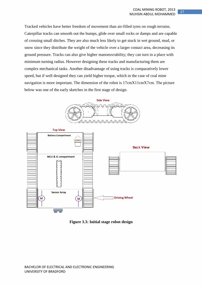
Tracked vehicles have better freedom of movement than air-filled tyres on rough terrains.
Caterpillar tracks can smooth out the bumps, glide over small rocks or damps and are capable
of crossing small ditches. They are also much less likely to get stuck in wet ground, mud, or
snow since they distribute the weight of the vehicle over a larger contact area, decreasing its
ground pressure. Tracks can also give higher manoeuvrability; they can turn in a place with
minimum turning radius. However designing these tracks and manufacturing them are
complex mechanical tasks. Another disadvantage of using tracks is comparatively lower
speed, but if well designed they can yield higher torque, which in the case of coal mine
navigation is more important. The dimension of the robot is 17cmX11cmX7cm. The picture
below was one of the early sketches in the first stage of design.
Figure 3.3: Initial stage robot design

BACHELOR OF ELECTRICAL AND ELECTRONIC ENGINEERING UNIVERSITY OF BRADFORD
28 COAL MINING ROBOT, 2013
MUHSIN ABDUL MOHAMMED
3.1.1 Differential Drive
The steering of an unmanned robot is a very important aspect. In this robot the instrument
which drives the robot is two DC motors (discussed in detail under title 3.1.2 Motors). And
the sensor involved in learning the environment is a pair of ultrasonic transceivers.
Differential drive is technique of controlling a robot with simply two motorized wheels. It
does not require an axle to turn the pair of wheels, which means it can get the maximum
turning radius, which is a distinct quality in a constrained space of a coal mine. It is perhaps
the simplest mode of steering a robot as it only requires a pair of motors.
The working principle of the differential robot is assumed in the term ‘Differential’ i.e. by the
difference in the turning speed of one of the two or both the motors, the robot can be turned.
For example by keeping the left wheel still and rotating the right wheel forward the robot will
turn Left. By rotating both the wheels in opposite directions the robot can be moved
clockwise or counter clockwise. By applying same rotation speed in both the wheels the robot
can be moved forward or backward.
Figure 3.4: Differential Drive System
From the figure above the algorithm for driving the coal mine robot can be developed.

BACHELOR OF ELECTRICAL AND ELECTRONIC ENGINEERING UNIVERSITY OF BRADFORD
29 COAL MINING ROBOT, 2013
MUHSIN ABDUL MOHAMMED
Pseudo code:
Get INPUT Reading From Ultrasonic Sensor
IF Sufficient Distance in Front
Move FORWARD
Turn both wheels forward at same speed
ELSE
Move BACKWARD OR Turn SIDEWAYS
Turn both wheels backward at same speed
Turn both wheels in opposite directions, Accordingly
3.1.2 Motor
As discussed under the title locomotion, there are several engines which can be used to drive
the robot. Given the terrain, wheel based chassis were finalised to use. To drive a wheeled
robot a Motor is required. There are several types of motors available for this purpose,
classified based on the mechanism there are simple DC motors, Servo motors, Stepper
motors, linear motor and so on. For this project the motor is controlled based on the values
from a proximity sensor, and it has to run for long period of time without any interruption.
Therefore the motor requires a combination of good rpm and torque. RPM is required
because it has to cover wider area of a coal mine in minimum time and torque is required as
the surface of a coal mine can be rocky and uneven. It does not require an accurate angular
movement therefore a fitting choice for this function is a Geared DC motor.
DC motor is an electric motor that runs on direct current (DC) electricity. Two types of DC
motors are Brush and Brushless DC motor. Brushed DC electric motor generates torque
directly from DC power supplied to the motor by using internal commutation, stationary
magnets (permanent or electromagnets), and rotating electrical magnets. Brushless DC
motors use a rotating permanent magnet or soft magnetic core in the rotor, and stationary
electrical magnets on the motor housing.

BACHELOR OF ELECTRICAL AND ELECTRONIC ENGINEERING UNIVERSITY OF BRADFORD
30 COAL MINING ROBOT, 2013
MUHSIN ABDUL MOHAMMED
DC motor has a two wire connection. All drive power is supplied over these two wires. When
a DC motor is turned on, it just starts spinning round and round. Most DC motors are pretty
fast, about 5000 RPM, depending on its characteristics.
With the DC motor, its speed (or more accurately, its power level) is controlled using a
technique named pulse width modulation, or simply PWM. This is idea of controlling the
motor’s power level by strobing the power on and off. If the power is switched on and off fast
enough, then it just seems like the motor is running weaker—there’s no stuttering. This is
what PWM means when referring to DC motors. The key concept here is duty cycle—the
percentage of “on time” versus “off time.” If the power is ON only half of the time, the motor
runs with half the power of its full-on operation. This leads to one of the disadvantages of dc
motor; it is that to change its direction the polarity of the DC supply has to be changed. The
figure below shows how a change in electric supply can change the resulting magnetic force.
Figure 3.5: DC motor working principle
The Exact DC motor used on this robot is a pair of 150:1 Micro Metal Gear motor. It is light
weight (10g each); the gears produce a Stall torque of 1.1kg/cm, which is good enough to
hike a rough coal mine as the whole robot is built with low weight materials. It runs at full
RPM of 85 at DC 6v supply. It has a free run current of 40mA and stall current of 360mA.

BACHELOR OF ELECTRICAL AND ELECTRONIC ENGINEERING UNIVERSITY OF BRADFORD
31 COAL MINING ROBOT, 2013
MUHSIN ABDUL MOHAMMED
Figure 3.6: Dimension of the DC motor used
3.1.3 Drivers
As discussed in the earlier title one of the disadvantage of using a DC motor is that to switch
the direction of the rotation of a DC motor the connection has to be switched, in other words
the polarity has to be changed. Doing so is a physical act and it is impossible to do it using
any binary programming. To do this task we can use a Motor Driver circuit. One of the most
common driver circuits to drive a motor in forward and reverse is an H-bridge. . The H-
Bridge is the link between digital circuitry and mechanical action. The H-bridge gets its
name from the structure of the basic circuit by which it operates.
Figure 3.7: Basic H-Bridge Schematics
From the figure it can be observed that there are four switches critical to the H-Bridge design.
By opening and closing them accordingly we can run the motors forward or backward. If S1

BACHELOR OF ELECTRICAL AND ELECTRONIC ENGINEERING UNIVERSITY OF BRADFORD
32 COAL MINING ROBOT, 2013
MUHSIN ABDUL MOHAMMED
and S4 are to closed the motor will run clockwise. If S3 and S2 is to be closed the motor will
run counter clockwise. However closing all the switches together should be avoided, because
it will cause a short circuit. Using physical switch will be unrealistic the control unit is a
microcontroller. Therefore transistors can be used; as they are sold state switches applying a
small current on the base can close the circuit.
Note that the configuration shown above can only be used to operate one Motor at a time, and
in this project there are two DC motors and they operate in full potential at 9V, which is
higher than the voltage in which the rest of the circuit operates (including MCU, Sensors, &
Bluetooth). This means that in order for fully functioning H-Bridge matching the criterions of
the project, it requires several Transistors, voltage Regulators, Op Amps and other passive
components. There is also chance of noise, which means an additional filter circuit has to be
designed.
L293D IC
But instead of designing a complex yet unstable H-Bridge using transistors and other
components from scratch a readymade IC can be used, which meets the project requirements.
L293D is a Quadruple high-current half-H driver. It is designed to provide bidirectional drive
currents of up to 600-mA at voltages from 4.5 V to 36 V (Anon, 2004). The L293D can also
operate two DC motors at a time.
Figure 3.8: Block Diagram of L293D IC

BACHELOR OF ELECTRICAL AND ELECTRONIC ENGINEERING UNIVERSITY OF BRADFORD
33 COAL MINING ROBOT, 2013
MUHSIN ABDUL MOHAMMED
Figure 3.9: In-project Implementation of L293D IC
Between the L293D H-Bridge IC and the Atmega328p Microcontroller there will be four
connections, as shown in the implementation figure above. By giving a High or Low signal
the two motors can be driven forward and backward accordingly. As the outputs from MCU
has only to be High or Low, the digital pins in the MCU can be used for this purpose. So first
four digital pins has to be declared:
Pins PD7, PB1, PB2, and PB3 (pin number 13, 15, 16, and 17 of the MCU respectively) are
Digital pins in Atmega328p, using the Arduino IDE(explained in detail under title 3.3
Arduino IDE) these pins are declared as 7, 9, 10 & 11. The variable names used are
Motor1Pin1, Motor1Pin2, Motor2Pin1 and Motor2Pin2, which are respectively connected to
the pins 2, 7, 10 & 15 of the L293D IC. As in the fragment of code given above it can be
observed that for declaring the variable the keyword “const” is used. The const keyword
stands for constant. It is a variable qualifier that amends the behaviour of the variable,
making a variable "read-only". This means that the variable can be used just as any other
variable of its type, but its value cannot be changed. This is required as the pins assigned are
not to be changed under any circumstance. The conventional C programming equivalent is
#Define, which can also be used instead of const.

BACHELOR OF ELECTRICAL AND ELECTRONIC ENGINEERING UNIVERSITY OF BRADFORD
34 COAL MINING ROBOT, 2013
MUHSIN ABDUL MOHAMMED
Syntax
#define constantName value //value of pin number
Once the variables are declared, the state (HIGH or LOW) of the pins has to be defined in
view of that. There are five primary movements of the motor to be defined they are Forward,
Backward, Right, Left and Stop. The easiest and efficient way of doing this is by creating
functions for each task, this way the conditions are appropriate the program can just call these
functions. The functions are defined as follows:
Now when the ultrasonic sensors return the distance, it can be used to determine the
direction in which the robot has to go. Once the direction is determined the above functions
can be called.

BACHELOR OF ELECTRICAL AND ELECTRONIC ENGINEERING UNIVERSITY OF BRADFORD
35 COAL MINING ROBOT, 2013
MUHSIN ABDUL MOHAMMED
3.2 Atmel Atmega328P
The ATmega328P chip is used in this project as the microcontroller. The significance of the
first two digits is to stipulate that the AVR core consists of variety of instruction set with 32
general purpose working registers which are connected directly to the Arithmetic Logical
Unit (ALU), tolerating two independent registers to be retrieved in one single instruction
executed in one clock cycle. The subsequent architecture is more programmable efficient
while attaining data transfer rates up to ten times quicker than other CISC microcontrollers.
The last digit is to indicate the 8 bit bi-directional port. It is certainly the head of the system
which is controlling the various modules. The AVR is a modified Harvard architecture 8-bit
RISC single chip microcontroller which was developed by Atmel in 1996. The AVR was one
of the first microcontroller families to use on-chip flash memory for program storage, as
opposed to one-time programmable ROM, EPROM, or EEPROM used by other
microcontrollers at the time.
Figure 3.10: ATmega328P pin mapping
The high-performance Atmel pico Power 8-bit AVR RISC-based microcontroller combines
32KB ISP flash memory with read-while-write capabilities, 1024B EEPROM, 2KB SRAM,
23 general purpose I/O lines, 32 general purpose working registers, three flexible

BACHELOR OF ELECTRICAL AND ELECTRONIC ENGINEERING UNIVERSITY OF BRADFORD
36 COAL MINING ROBOT, 2013
MUHSIN ABDUL MOHAMMED
timer/counters with compare modes, internal and external interrupts, serial programmable
USART, a byte-oriented 2-wire serial interface, SPI serial port, a 6-channel 10-bit A/D
converter (8-channels in TQFP and QFN/MLF packages), programmable watchdog timer
with internal oscillator, and five software selectable power saving modes. The device
operates between 1.8-5.5 volts. By executing powerful instructions in a single clock cycle,
the device achieves throughputs approaching 1 MIPS per MHz, balancing power
consumption and processing speed (Atmel Corporation,).
3.3 Arduino UNO
To program the ATmega328P Microcontroller a Serial communicator is required. Serial
communication is most widespread interface between microcontroller and computer. UART
is one of the serial interfaces which are widely used. A Universal Asynchronous
Receiver/Transmitter (UART) is a piece of computer hardware that translates data between
parallel and serial forms. Classically, most serial interface from microcontroller to computer
is done through serial port (DB9). However, since computer serial port used RS232 protocol
and microcontroller used TTL UART, a level shifter is needed between these interfaces.
There are several level shifters available in the market, some of which supports USB plug and
play.
Figure 3.11: Serial communication between MCU and Computer

BACHELOR OF ELECTRICAL AND ELECTRONIC ENGINEERING UNIVERSITY OF BRADFORD
37 COAL MINING ROBOT, 2013
MUHSIN ABDUL MOHAMMED
But in most of the times the level shifter are unstable to use due to its design and more than
one software is required to convert the programming on C to hex or machine language and
maybe another software to interface between the Microcontroller and computer.
Arduino UNO is an alternative to this solution, the internal board of Arduino consists of all
the necessary ICs for communication. It is also build compact into a PCB which has
connectors for fast and easy prototyping.
Figure 3.12: An official Arduino Uno with descriptions of the I/O locations
3.3.1 Arduino IDE
The Arduino integrated development environment (IDE) is a cross-platform application
written in Java, and is derived from the IDE for the Processing programming language and
the Wiring projects. It includes a code editor which is capable of compiling and uploading
programs to the board with a single click. A program or code written for Arduino is called a
"sketch”.

BACHELOR OF ELECTRICAL AND ELECTRONIC ENGINEERING UNIVERSITY OF BRADFORD
38 COAL MINING ROBOT, 2013
MUHSIN ABDUL MOHAMMED
Figure 3.13: Arduino code editor
Arduino programs are written in C or C++. The Arduino IDE comes with a software library
called "Wiring" from the original Wiring project, which makes many common input/output
operations much efficient. Users only need define two functions to make a runnable cyclic
executive program:
setup(): a function run once at the start of a program that can initialize settings
loop(): a function called repeatedly until the board powers off
The Arduino IDE uses the GNU tool chain and AVR Libc to compile programs, and uses
avrdude to upload programs to the board.
3.4 Sensors
The project objectives require the robot to detect gases, temperature and to move
autonomously. As mentioned in the literature review, there has been massive change in the
technology and equipment used in detecting the gases under different circumstances, there it
is also mentioned the common and toxic gases present in the coal mine. The major ones are

BACHELOR OF ELECTRICAL AND ELECTRONIC ENGINEERING UNIVERSITY OF BRADFORD
39 COAL MINING ROBOT, 2013
MUHSIN ABDUL MOHAMMED
monoxides of carbon, methane, butane and other natural gases. The temperature rise in a coal
mine can be a result of fire or pressure. In this title the hardware sensors used for detecting
different surroundings will be discussed, together with the software development.
3.4.1 Toxic Gas Sensors
There are several atmosphere and gas sensors available in the market today. Some of them
are for specific industries, and some for common safety measures. The different technologies
of gas sensors where also discussed in chapter 1. The gas sensors used in this project is from
the MQ series of gas sensors.
3.4.1.1 MQ Gas sensor Series
The MQ series of gas sensors use a small heater inside with an electro-chemical sensor. They
are sensitive for a range of gasses and are most commonly used indoors at room temperature,
due to the small size of the sensor filaments. The list of detectors and their sensitivity of
gases:
Sensor
Name
Sensitivity for:
MQ-2 Methane, Butane, LPG, smoke
MQ-3 Alcohol, Ethanol, smoke
MQ-4 Methane, CNG Gas
MQ-5 Natural gas, LPG
MQ-6 LPG, butane gas
MQ-7 Carbon Monoxide
MQ-8 Hydrogen Gas
MQ-9 Carbon Monoxide, flammable
gasses
MQ-131 Ozone
MQ-135 Benzene, Alcohol, smoke
Table 3.2: MQ gas sensors
The specific sensors used for this project are MQ-2, MQ-4, & MQ-9. These sensors
combined can detect the presence of Methane, Butane, smoke, LPG, CNG, Carbon
Monoxide, and flammable gasses. These are the most abundant, toxic and flammable gasses

BACHELOR OF ELECTRICAL AND ELECTRONIC ENGINEERING UNIVERSITY OF BRADFORD
40 COAL MINING ROBOT, 2013
MUHSIN ABDUL MOHAMMED
found in the coal mines. The working principle of these sensors is similar and they are
discussed under the title 2.5.3 Semiconductor type gas sensors in Chapter 2: literature riview.
Figure 3.14: Building Block and recommended circuit connection.
3.4.1.2 Calibration and Coding for Gas sensors
As mentioned before in the theory part these sensors have a built in heater which is crucial in
sensing the gas level around it. This heater operates in 5-6V range. For a stable reading the
manufacturer recommends a Burn-in time for the MQ gas sensors, which around 24 hours.
This has to be only done once; from then on the Gas sensor becomes stable by heating around
3 minutes at 5V, before usage. This is pre-heat of 3 minutes is not included in the coding,
since even during this period of waiting the sensor can produce approximate results. This
conclusion was derived by conducting trial and errors.
A better calibration for the sensor is by connecting a load resistor, of the value from 2kOhm
to 47kOhm. The lower the load-resistance the lesser the sensitivity and the higher the load-
resistance the less accurate the result for higher concentrations of gas. But one problem with
this method is that it requires a known concentration of gas in the atmosphere, which was
unable to come up with because of the limitation in the lab equipment. Therefore the load-
resistor was tuned to a medium range.

BACHELOR OF ELECTRICAL AND ELECTRONIC ENGINEERING UNIVERSITY OF BRADFORD
41 COAL MINING ROBOT, 2013
MUHSIN ABDUL MOHAMMED
The sensors where connected to the analogue pins of the MCU. As the input voltage to the
sensor was ~5V, the sensor returns a value from 0 to 1023. This is because the ATmega32bp
controllers used for the Arduino contain an on-board 6 channel analogue-to-digital converter
(ADC). The converter has 10 bit resolution thus returning integers from 0 to 1023. The first
part of the coding is to declare two variables for reading the values from the gas sensors:
The returning values are from a range of 0-1023, therefore the data-type used is “int”. “int”
can store up to 16-bit(2-byte) of data, which is more than sufficient in this case. Now the
value has to be read from the sensors. Defining the variables:
The function analogRead() is a pre written code in the Arduino IDE. It reads the value from
the specified analogue pins. In this case the pins are A0 and A1.
Syntax
Variable = analogRead(pin);
As mentioned above the sensor is supplied with 5v and the arduino board has 10-bit ADC
resolution. The analogRead() function therefore reads the voltage in the respective pin (which
will be between 0 and 5Volt), and will convert into an integer between 0-1023. I.e.
This reading is not converted to the standard PPM (parts per million) gas unit, because to do
so requires a known reading from a known amount of gas. Nevertheless the integer reading
(0-1023) was put into trial and error tests to find out a hazardous level for creating an alert.
For the MQ4 sensor a value higher than 500 is considered to be hazardous and for the MQ9
sensor a value higher than 100 is considered hazardous (the reason for choosing these values
are further discussed in chapter discussion.). The coding for creating the alert and displaying
in the control panel is discussed under the title software overview.

BACHELOR OF ELECTRICAL AND ELECTRONIC ENGINEERING UNIVERSITY OF BRADFORD
42 COAL MINING ROBOT, 2013
MUHSIN ABDUL MOHAMMED
3.4.2 Temperature Sensor
The LM35 series are precision IC temperature sensors, which gives an output voltage linearly
proportional to the Centigrade temperature. The LM35 does not require any external
calibration or trimming to provide typical accuracies of ±¼°C at room temperature and ±¾°C
over a full −55°C to +150°C temperature range. The LM35 sensor is low cost and durable.
The device operates with a DC power supply of the range 4V to 30v. The current drawn by
the sensor is only 60 μA making it appropriate for a low power profile robot. The heat
generated by the sensor itself is very low, which is less than 0.1°C in still air, making it even
more accurate. The LM35 sensor is sealed air tight thus moisture or other gases in the
atmosphere cannot affect it. The sensor increments at +10mV/°C scale factor.
Figure 3.15: LM35 Pin Values
The output from the sensor is analogue therefore an analogue pin from the MCU has to be
used for LM53. In coding first a variable for storing the value of the temperature is declared:
The reason why the variable is declared in “int” is because for this project precise
temperature (i.e. in float) is not required, because the temperature we are dealing in a coal
mine is more than 35°C. Now the variable needs to get the reading from the sensor:

BACHELOR OF ELECTRICAL AND ELECTRONIC ENGINEERING UNIVERSITY OF BRADFORD
43 COAL MINING ROBOT, 2013
MUHSIN ABDUL MOHAMMED
As mentioned earlier increment in every 10mv is an increment in 1 degree Celsius. But the
MCU is not getting the reading in 10mv. It is getting the value from an on-board 10-bit ADC,
an integer value between 0-1023 for the corresponding change in 0-5v. Hence the integer
value has to be converted back to value in terms of milli-volt. For this purpose we divide the
received value with 1024 (2^10 (10-bit ADC)), and then multiply it with 5 (because the
supply voltage is 5v). Then again obtained value is in voltage, so to convert to milli-voltage
we can multiply with 1000. Now we have the value of increment in terms of 1mv. But the
LM35 increments in term of 10mv, therefore with the last gotten value a 10 has to be divided.
Pseudo code:
Coding:
3.4.3 Ultrasonic Ranging Module HC- SR04
The coal mine robot is an unmanned robot. For it to roam around autonomously it needs to
have an eye to see its surrounding. There are many sensors to do make this task starting from
LDR sensors to Laser and satellite guided navigation. In this project it seemed fit to use an
ultrasonic sensor, because it does the intended job. That is the coal mine is a dark place and to
navigate there using a camera is very difficult and even with a lighting system there can be
smoke and dust particle which would turn out to be a problem. Ultrasonic sensors are pretty
neat solution because it works by propagating pulses of ultrasound and waiting for them to
come back.

BACHELOR OF ELECTRICAL AND ELECTRONIC ENGINEERING UNIVERSITY OF BRADFORD
44 COAL MINING ROBOT, 2013
MUHSIN ABDUL MOHAMMED
In this project the ultrasonic sensor used is the HC-SR04 Ultrasonic Ranging Module.
Figure 3.16: HC-SRO4 module Schematic and its range of sight
In this module there is a transmitter and receiver, the transmitter sends pulses of ultrasound
frequency upon triggering and the receiver waits for it to return. The Timing diagram is
shown in the figure below.
Figure 3.17: Timing diagram
By supplying a short 10uS pulse to the trigger input, the module will send out an 8 cycle
burst of ultrasound at 40 kHz from the transmitter. After that the receiver will be expected to
receive an echo. The Echo is from a distant object. The pulse width and the range are in ratio.
Now the range of the time interval between sending trigger signal and receiving echo signal
is to be calculated. In the figure above the graph shows a practical visibility of 30 degree,
which is sufficient for the size of the robot in this project, but for a bigger robot or for more

BACHELOR OF ELECTRICAL AND ELECTRONIC ENGINEERING UNIVERSITY OF BRADFORD
45 COAL MINING ROBOT, 2013
MUHSIN ABDUL MOHAMMED
accuracy multiple sensors are to be used or a turning motor has to be used. The manufacturer
suggest on using a constant to be divided from the time obtained to convert it to distance. I.e.
for getting the distance in centimetre divide time by 58. This constant can be more accurately
calculated. My calculation is as follows:
The calculation is very close to the manufacture recommendation, therefore for 58 was used
in the coding process. The algorithm developed from the theory:
Algorithm:
Step 1: Supply Pulse (for 10microseconds)
Step 2: Receive Echo
Step 3: Duration = Triggering time – Echo Receive time. (In microseconds)
Step 4: Distance = Duration / 58
Step 5: IF (Distance>4)
Move (Forward)
Else
Move (Reverse)
Move (Right/Left)
Step 6: Repeat from Step 1
In the algorithm and coding a distance greater than 4cm is found to be a safe distance for the
robot to move forward, thus it was used. The coding developed from the algorithm:

BACHELOR OF ELECTRICAL AND ELECTRONIC ENGINEERING UNIVERSITY OF BRADFORD
46 COAL MINING ROBOT, 2013
MUHSIN ABDUL MOHAMMED
In the arduino the trigger pins where connected to the digital pins. The digital pins defined
are:
#define trigPin 13
#define echoPin 12
digitalWrite() is the function used to write HIGH or a LOW value to a digital pin.
Syntax
digitalWrite(pin, value)
delayMicroseconds() is a function used to pause the program for the amount of time in
microseconds specified as parameter.
pulseIn() is probably the most important function in this code. What is does is, it Reads a
pulse (either HIGH or LOW) on a pin. For example, if value is HIGH, pulseIn() waits for the
pin to go HIGH, starts timing, then waits for the pin to go LOW and stops timing then returns
the length of the pulse in microseconds.

BACHELOR OF ELECTRICAL AND ELECTRONIC ENGINEERING UNIVERSITY OF BRADFORD
47 COAL MINING ROBOT, 2013
MUHSIN ABDUL MOHAMMED
Syntax
pulseIn(pin, value)
pulseIn(pin, value, timeout)
3.5 Communication
For this project Bluetooth was used because most devices like personal computers and almost
all the smartphone has Bluetooth module embedded in them, which gives it the advantage of
economic and technical feasibility.
Following are the most commonly used market products for wireless communication:
BlueBee Xbee Xbee-Wifi RF Transciever
Technology Bluetooth Zigbee Wifi RF
IEEE standard 802.15.1 802.15.4 802.11
Rate of transfer 2.1Mbps /
160Kbps
250Kbps 3.5Mbps /
1Mbps
>2Mbps
Frequency 2.4GHz ISM
2.4GHz
ISM
2.4GHz
2.4GHz
Voltage of
operation
3.3DC/ 50mA 2.8DC/
40mA
3.3DC/
50mA
3.6DC
Range (Meter) 20~30m 30m++ 30m+
Price (MYR) 68.00 147.00 200.00 30.00
Number of Units
Required for
Communication
One* Two One^ Two
Table 3.3: most common wireless communication antennas
*Assuming the receiving unit is a computer or smartphone and already has a Bluetooth
implanted.
^ Assuming the receiving unit is a computer or smartphone and already has a Wifi implanted.

BACHELOR OF ELECTRICAL AND ELECTRONIC ENGINEERING UNIVERSITY OF BRADFORD
48 COAL MINING ROBOT, 2013
MUHSIN ABDUL MOHAMMED
3.5.1 BlueBee
The last topic to be accomplished in the project is to get the MCU communicate with control
unit. For this in this project Bluetooth is used and the specific module used is BlueBee which
is a Bluetooth wireless module manufactured and sold by Cytron Technologies Sdn.Bhd,
Malaysia. It is designed to adapt the form factor of the famous XBee Modules. BlueBee
module has an on-board antenna which can provide better signal quality. It is like a
transparent serial port, it can be operated with a variety of Bluetooth adapters and devices
which support Bluetooth.
Figure 3.18: BlueBee Module
There are 2 modes on BlueBee which is Transparent mode and AT mode. The baudrate of
module may be set using AT mode. To communicate with BlueBee any terminal emulator
programs can be used like PuTTY, Hyperterminal or Terea Term. For the purpose of this
project PuTTY was used.

BACHELOR OF ELECTRICAL AND ELECTRONIC ENGINEERING UNIVERSITY OF BRADFORD
49 COAL MINING ROBOT, 2013
MUHSIN ABDUL MOHAMMED
Figure 3.19: PuTTY window
The Bluetooth module is just like a serial port, all that matters is the number of COM Port
(for Windows OS) where the data is received and the Baud rate in which it is received. By
feeding this information the emulator can receive the data from the Microcontroller send via
Bluetooth. Or other programs can be written using VB, C#, Java or any other GUI
Developing programs, to receive the data. By developing custom software the data can be
represented more graphically. In this project a code was developed using “Processing”
(JAVA based Development tool) which will be discussed in the Software overview.
BlueBee operates at 3.3vDC; thus it is very power efficient. But a small fluctuation can
damage the module, therefore a separate module for power regulation was used.
Between the ATmega328p Microcontroller and the Bluetooth there are only two connections
because the interface is serial. The connections are TX*(transmit in Bluetooth) to
RX(Receiver in MCU) and RX*(Receiver in Bluetooth) and TX(transmit in MCU). In this
project the data is only sent from the MCU to the Bluetooth therefore only one connection is
required. TX*RX.

BACHELOR OF ELECTRICAL AND ELECTRONIC ENGINEERING UNIVERSITY OF BRADFORD
50 COAL MINING ROBOT, 2013
MUHSIN ABDUL MOHAMMED
3.6 Software Overview
Below is the flowchart by which the Microcontroller will execute the tasks:
Flowchart
POWER UP
Activate Ultrasonic sensor – By applying 10µs of HIGH pulse
on trigger
Convert Duration to Distance.
[Dist = Dur/58 ]
Receive Echo Duration
Move Forward
Move Backward
Move Forward
Move Right/Left
If
Distance
>= 4cm
YES
NO
Initialize Survey
mode: Start
Temperature and
GAS sensors.

BACHELOR OF ELECTRICAL AND ELECTRONIC ENGINEERING UNIVERSITY OF BRADFORD
51 COAL MINING ROBOT, 2013
MUHSIN ABDUL MOHAMMED
If temperature <= 45
If GAS1 <= 500
If GAS2 <= 100
NO
NO
NO Beep Alarm &
“Temperature
warning”
Beep Alarm &
print ”Coal
Fumes notice”
Beep Alarm &
print “Butane or
Methane Leak”
print “Safe
temperature
level”
print “Safe
Butane and
Methane level”
print “Safe Coal
Fumes level”
YES
YES
YES
Print value of
Temperature
in , Gas levels.

BACHELOR OF ELECTRICAL AND ELECTRONIC ENGINEERING UNIVERSITY OF BRADFORD
52 COAL MINING ROBOT, 2013
MUHSIN ABDUL MOHAMMED
The coding regarding each part has been discussed under appropriate titles in this chapter
(Methodology). The entire programming is included in Appendix A.
3.7 Graphical User Interface
The graphical interface for reading the temperature sensor was designed in processing the
coding for this is included in Appendix B. The interface and its results are discussed under
the Chapter 4: Test and Results.

BACHELOR OF ELECTRICAL AND ELECTRONIC ENGINEERING UNIVERSITY OF BRADFORD
53 COAL MINING ROBOT, 2013
MUHSIN ABDUL MOHAMMED
Chapter 4: Test and Results
In this chapter the outcomes of the project is discussed namely the mechanical model,
Independence of the robot, working of the sensors, reception of data using Bluetooth and
GUI.
4.1 Mechanical Design
The robot is build rigid enough for a prototype; it is made from plastic and reinforced with
carbon fibre sticker. All the circuits fit in and are screwed properly to the body, so it is shock
proof. To reduce the complexity most of the components are prototyped into PCBs. The
power supply is an array of rechargeable 9V Batteries. The pictures of the robot, Schematics
and PCB designs are included in the Appendix.
4.2 Independence of the Robot
The robot has one Ultrasonic sensor fixed in the front, which can detect anything in front of
it. An obstacle was placed in front of the ultrasonic sensor at different distances and the
distance was measured using a ruler and the Sensor itself.
Figure 4.1: Set up for the Obstacle Test
The comparison in data is shown in the Table 4.1.

BACHELOR OF ELECTRICAL AND ELECTRONIC ENGINEERING UNIVERSITY OF BRADFORD
54 COAL MINING ROBOT, 2013
MUHSIN ABDUL MOHAMMED
Distance (cm) –
Measured using ruler
Distance (cm) –
Measured using
sensor
5 5.15
10 10.25
20 20.31
30 30.50
50 47.40
70 50.73
80 50.97
Table 4.1: Results from sensor and real measurement
The precision is very close to ±7mm for distances less than 30cm, although further distances
where measured with less accuracy. It doesn’t really matter because the sensors task is to find
any obstacles in a range of 4cm and avoid them by changing the direction.
4.3 Working of the sensor
The detections sensors used are temperature sensor, MQ4 and MQ9 gas sensor. The
temperature sensor is producing very accurate results, as it was compared with other sensors
to make sure about the result. Testing the accurate results of MQ4 and MQ9 sensors are very
difficult, because the availability of the natural gases is restricted. Therefore alternates had to
be used for demonstration purposes and testing. Instead of Methane in MQ4 sensor, butane
from a cigarette lamp sensor had to be used, this showed the rise in the value, but the
percentage of the gas in comparison to the atmosphere where not able to deduce. For this a
proper chemical lab and equipment are required. Similarly instead of using pure carbon
monoxide (which is highly toxic) in MQ9 sensor, for safety purposes a burned out candle
smoke was used, this is also CO, because of the absence of oxygen. Again not an accurate
mode of testing, but the lack of resources it was required.
Nevertheless the datasheet was used to determine the properties of the MQ series sensors, and
even without proper testing a value was cooked up, using some simple set ups. A gas leak
from the cigarette lamp within seconds hiked the MQ4 sensor ADC integer output from 300

BACHELOR OF ELECTRICAL AND ELECTRONIC ENGINEERING UNIVERSITY OF BRADFORD
55 COAL MINING ROBOT, 2013
MUHSIN ABDUL MOHAMMED
to 500. From this analysis this value was used to give a warning. Similar test conducted in
MQ9 sensor the hike observed was from 40 to 100.
4.4 Reception of Wireless Data
As mentioned in the Chapter 3 Methodology the serial data from the Bluetooth module was
received using a terminal emulator called PuTTY. The range of the Bluetooth module
specified by the manufacturer was about 30meters. But from the test conducted it was found
that in indoor the range for perfect reception at 9600Baud rate is 10meters. After this point
the data is transmitting at a lower rate and even the data starts to scramble.
One problem faced with the Bluetooth reception was that the data was fluctuating, for
example if the data from the temperature sensor was 28 , the data received could be 0, 43,
12, 56, 60, 4, 9, 67, 14, 15. This created huge confusion, but with close observation it was
found that somehow the data transmitted is scrambled. But taking the average of data over a
period of time could get the accurate results. For example in the case above:
Average = 27.6 .
Therefore this method of sampling was used in all the transmitted data.
The coding for sampling was written as follows:
for (int x=0; x<500;x++) { pot = analogRead(A0); tempC = (5.0 * pot * 100.0) / 1024; i[x]=tempC; sum=i[x]+sum; } tempC=sum/500; 500 samples of Temperature was taken to get an average, the result was accurate by doing
this.

BACHELOR OF ELECTRICAL AND ELECTRONIC ENGINEERING UNIVERSITY OF BRADFORD
56 COAL MINING ROBOT, 2013
MUHSIN ABDUL MOHAMMED
The results obtained from the sensors using UART to USB serial cable:
Figure 4.2: Result obtained using UART-USB cable
Notice the COM4 in the top of the serial window; COM4 in the respective computer used
was only for connecting ATmega328p via Arduino,

BACHELOR OF ELECTRICAL AND ELECTRONIC ENGINEERING UNIVERSITY OF BRADFORD
57 COAL MINING ROBOT, 2013
MUHSIN ABDUL MOHAMMED
The results obtained from the sensors using BlueBee Bluetooth module in PC:
Figure 4.3: Results obtained from the sensors using BlueBee.
Notice the software used for obtaining this result is PuTTY and the COM port is COM5
which is used by Bluetooth receiver only.

BACHELOR OF ELECTRICAL AND ELECTRONIC ENGINEERING UNIVERSITY OF BRADFORD
58 COAL MINING ROBOT, 2013
MUHSIN ABDUL MOHAMMED
The Results obtained in an Android Smartphone:
1.
Figure 4.4: Screenshot of the reading received on an Android Mobile

BACHELOR OF ELECTRICAL AND ELECTRONIC ENGINEERING UNIVERSITY OF BRADFORD
59 COAL MINING ROBOT, 2013
MUHSIN ABDUL MOHAMMED
4.5 Graphical User Interface (GUI)
The GUI for better understanding of data for this project was written in Processing, a Java
based programming environment. The coding for this program is included in the Appendix B.
The coding runs smoothly and gives a visual impact. Due to the limitation of understanding
in the particular programming language, it was not successful to transmit the data via
Bluetooth module, but the data could be read properly by using a UART cable from the MCU
to the PC. The screenshot of the temperature reading in the form of a graph where a safe level
of temperature is displayed in green, a precautionary level is displayed is yellow and a
hazardous level is displayed in red, with the real time reading on the right corner, is displayed
below:
Figure 4.5: Screenshot from Processing

BACHELOR OF ELECTRICAL AND ELECTRONIC ENGINEERING UNIVERSITY OF BRADFORD
60 COAL MINING ROBOT, 2013
MUHSIN ABDUL MOHAMMED
Chapter 5: Discussion
5.1 Investigation
The project from its beginning was examined in an industrial point of view. The necessary of
such a research was highly relevant due to the continuous accidents happening in the coal
mines around the world. The literature review proved that there are technologies which can
give solution to this problem, but still the initiative to support such project was lacking from
an industrial prospective. Mainly due to the fact that most Coal mines in the world are in
developing countries and their priority of Safety are sometimes misplaced with the priority of
wages and revenues. From this conclusion a project which can be viable for these consumer
where to be developed, a new market possibly, based on the principles of valuing time, and
money. That is if the robot is feasible with the current technologies used by them and if they
are made not from the top quality products, but a resultant of Quality and value materials, and
then there is a potential market for this project.
5.2 Validity of the prototype
The prototype was designed and realized on the principle of demonstrating the possibility and
further study for such a robot. The element of mass production was less of a concern. The
prototype could demonstrate that with modifications it can be enabled for mass production.
The reason why this is mentioned here because some elements in the project might not be the
exact fit rather it is glimpse of what could be. For example using Bluetooth in the mines is
not very practical because of the range, but using a real life solution can be extremely costly
and complex to design. Likewise the Body is made out of plastic, which won’t be suitable in
higher temperature.

BACHELOR OF ELECTRICAL AND ELECTRONIC ENGINEERING UNIVERSITY OF BRADFORD
61 COAL MINING ROBOT, 2013
MUHSIN ABDUL MOHAMMED
Chapter 6: Conclusion
The experience of doing this project was extremely rewarding, the years spent in learning the
theory was put to use. This felt fulfilling and self-reliant. , From a personal outlook the
project can be classified success for this reason. It could also be said successful in a
professional point of view because of achieving most of the objectives required by the
University.
Some limitations and lack of validity in some areas have been discussed in previous chapters.
This leaves a lot of room for improvement. The Robot itself is capable of getting the data,
transmitting it and moving around unmanned.
The project was done in Fragments; this has an impact in every aspect of this project.
Looking at the hardware it can be deduced that instead of creating 1 PCB to accommodate
everything, different layers of circuits where used. This means that the failure of one of these
circuits will not affect the other sensors. This could also be said in the case of programming,
every action was built into separate class or function for ease of access and troubleshooting.
The objectives or requirements expected from the project and its status and explanation in the
end.
Number Objective Status
1 Detect the toxic gases emitted from the
coal mine.
Achieved. For demonstration purposes
the robot can detect CH4, CO, coal
fumes, butane, and so on.
2 Detect the level of heat inside the coal
mine.
Achieved. The level of heat can be
detected with precision.
3 Indicate the name and the value of the
gases and the temperature inside the
coal mine regularly to the control
room.
Achieved. Using Bluetooth the data will
be transferred to the control room.
4 If level of the gases or temperature is
too high a voice warning signal must
be activated inside the coal mine.
Achieved. Not a voice warning but a
buzzer will be alarmed letting the
miners ready for rescue mission.
5 Graphical Interface in control room Partially achieved. With some tweaks in

BACHELOR OF ELECTRICAL AND ELECTRONIC ENGINEERING UNIVERSITY OF BRADFORD
62 COAL MINING ROBOT, 2013
MUHSIN ABDUL MOHAMMED
the programming this can be send to the
control room.
6 Autonomous movement Partially achieved. With additional cliff
sensors and 360 degree control the robot
can surf through any surroundings.
Table 6.1: Objectives and status of accomplishment.

BACHELOR OF ELECTRICAL AND ELECTRONIC ENGINEERING UNIVERSITY OF BRADFORD
63 COAL MINING ROBOT, 2013
MUHSIN ABDUL MOHAMMED
Chapter 7: Further improvement
With this pace of growth in the field of Robotics and Artificial Intelligence the scope for
further improvement are endless. Even though some of the further improvements from
current scopes can be:
1. An upgrade from the plastic body chassis to Carbon Reinforced Fibre Chassis which
are more light weight, and durable than most other materials like stainless steel and
iron frames.
2. Instead of the MQ series of gas detectors and industrial solution like the M40.M
sensors (discussed briefly in the literature review). They are easy to calibrate. Can
display O2, H2S, CO and CH4 all with extreme precision.
3. A compartment to store food or rescue gear. This is an easy improvement but an
extremely useful one. Because most of the time when an accident happens it will be
hard for a human to move around without proper precautions.
4. A camera and GPS integration, which can map the coal mine into the robots memory.
And further used for storing weak points inside the mine, in terms of gas Break outs
or surface tension. This could also be used by the rescue team to locate and
communicate in two ways with the miners.

BACHELOR OF ELECTRICAL AND ELECTRONIC ENGINEERING UNIVERSITY OF BRADFORD
64 COAL MINING ROBOT, 2013
MUHSIN ABDUL MOHAMMED
References
1. Anon. (2011). COAL INFORMATION. Available: http://www.worldcoal.org/coal/.
Last accessed 4th October 2013.
2. Anon. (2011). USES OF COAL. Available: http://www.worldcoal.org/coal/. Last
accessed 4th October 2013.
3. Britannica. (2013). Safety lamp. Available:
http://www.britannica.com/EBchecked/topic/516095/safety-lamp. Last accessed 18th
Aug 2013.
4. Anon. (2012). Coal & Electricity. Available: http://www.worldcoal.org/coal/. Last
accessed 4th October 2013.
5. Ashok K. Singha,R.V.K. Singhb, Mahendra P. Singhc, Hem Chandraa, N.K. Shuklaa.
(2007). Abstract. Mine fire gas indices and their application to Indian underground
coal mine fires. 69 (3), 192–204. [online]Available at :
<http://www.sciencedirect.com/science/article/pii/S0166516206000826 > [Accessed
13 October 2013].
6. Rio Tinto: Press Release. (2008). Rio Tinto and Komatsu to develop autonomous
haulage system for Pilbara iron ore operations. Available:
http://www.riotinto.com/media/media-releases-237_1885.aspx. Last accessed 18th
November 2013.
7. Anon. (). Gas Detector Technologies. Available:
http://www.thomasnet.com/articles/instruments-controls/How-Gas-Detectors-Work.
Last accessed 18th Aug 2013.
8. Anon. (). Measurement of Toxic Gases. Available:
http://www.thomasnet.com/articles/instruments-controls/How-Gas-Detectors-Work.
Last accessed 18th Aug 2013.
9. Anon. (). M40.M. Available: http://www.indsci.com/products/multi-gas-
detectors/m40m/#overview. Last accessed 1st September 2013.
10. Figaro. (). Operating principle of semiconductor type gas sensors. Available:
http://www.figaro.co.jp/en/item2.html. Last accessed 11th September 2013.
11. Anon. (2004). L293, L293D QUADRUPLE HALF-H DRIVERS. Available:
http://www.ti.com/lit/ds/symlink/l293d.pdf. Last accessed 18th October 2013.
12. Atmel Corporation. (). ATmega328P. Available:
http://www.atmel.com/devices/atmega328p.aspx. Last accessed 18th October 2013.

BACHELOR OF ELECTRICAL AND ELECTRONIC ENGINEERING UNIVERSITY OF BRADFORD
65 COAL MINING ROBOT, 2013
MUHSIN ABDUL MOHAMMED
APPENDICES
Appendix A: Coding for the Microcontroller
int MQ4 = 0; // first analog sensor
int MQ9 = 0; // second analog sensor
int LM35 = 0; // digital sensor
int inByte = 0; // incoming serial byte
const int Motor1Pin1 = 8;
const int Motor1Pin2 = 9;
const int Motor2Pin1 = 10;
const int Motor2Pin2 = 11;
#define trigPin 13
#define echoPin 12
void setup() //run once
{
Serial.begin(9600); //begin serial transmission at 9600 bauds
pinMode(Motor1Pin1, OUTPUT);
pinMode(Motor1Pin2, OUTPUT);
pinMode(Motor2Pin1, OUTPUT);
pinMode(Motor2Pin2, OUTPUT);
pinMode(trigPin, OUTPUT);
pinMode(echoPin, INPUT);
}
void loop() //keep on looping
{
long duration, distance;
digitalWrite(trigPin, LOW);

BACHELOR OF ELECTRICAL AND ELECTRONIC ENGINEERING UNIVERSITY OF BRADFORD
66 COAL MINING ROBOT, 2013
MUHSIN ABDUL MOHAMMED
delayMicroseconds(2);
digitalWrite(trigPin, HIGH);
delayMicroseconds(10);
digitalWrite(trigPin, LOW);
duration = pulseIn(echoPin, HIGH);
distance = (duration/2) / 29.1;
if (distance>4)
{
GoForward();
survOn();
}
else
{
GoBackward();
delay(300);
GoLeft();
delay(700);
}
}
void GoRight()
{
digitalWrite(Motor1Pin2, LOW);
digitalWrite(Motor1Pin1, HIGH);
digitalWrite(Motor2Pin2, LOW);
digitalWrite(Motor2Pin1, HIGH);
}
void GoLeft()
{
digitalWrite(Motor1Pin1, LOW);
digitalWrite(Motor1Pin2, HIGH);

BACHELOR OF ELECTRICAL AND ELECTRONIC ENGINEERING UNIVERSITY OF BRADFORD
67 COAL MINING ROBOT, 2013
MUHSIN ABDUL MOHAMMED
digitalWrite(Motor2Pin1, LOW);
digitalWrite(Motor2Pin2, HIGH);
}
void GoForward()
{
digitalWrite(Motor1Pin1, LOW);
digitalWrite(Motor1Pin2, HIGH);
digitalWrite(Motor2Pin2, LOW);
digitalWrite(Motor2Pin1, HIGH);
}
void GoBackward()
{
digitalWrite(Motor1Pin2, LOW);
digitalWrite(Motor1Pin1, HIGH);
digitalWrite(Motor2Pin1, LOW);
digitalWrite(Motor2Pin2, HIGH);
}
void Stop()
{
digitalWrite(Motor1Pin2, LOW);
digitalWrite(Motor1Pin1, LOW);
digitalWrite(Motor2Pin1, LOW);
digitalWrite(Motor2Pin2, LOW);
}
void survOn()
{
// get incoming byte:
inByte = Serial.read();
// read first analog input:
MQ4 = analogRead(A0);

BACHELOR OF ELECTRICAL AND ELECTRONIC ENGINEERING UNIVERSITY OF BRADFORD
68 COAL MINING ROBOT, 2013
MUHSIN ABDUL MOHAMMED
// read second analog input:
MQ9 = analogRead(A1);
// read switch, map it to 0 or 255L
LM35 = analogRead(A2);
// send sensor values:
LM35 = (5.0 * LM35 * 100.0) / 1024;
if (MQ4<500 && MQ9<100 && LM35<40)
{
allsafe();
delay(1000);
}
else
{
sensor1();
sensor2();
sensor3();
delay(1000);
}
}
void allsafe()
{
Serial.print(MQ4);
Serial.print(" - Methane, CNG Gas||||");
Serial.print(MQ9);
Serial.print(" - Carbon Monoxide, Flammable gas||||");
Serial.print(LM35);
Serial.println("°C||||");
Serial.println(" All Safe All Safe All Safe All Safe All Safe All Safe All
Safe ");
}

BACHELOR OF ELECTRICAL AND ELECTRONIC ENGINEERING UNIVERSITY OF BRADFORD
69 COAL MINING ROBOT, 2013
MUHSIN ABDUL MOHAMMED
void sensor1()
{
Serial.print(MQ4);
Serial.print(" - Methane, CNG Gas ");
if(MQ4>500)
{
Serial.println(" MAYDAY!!!!!!! Methane, CNG Gas level ALARMING");
}
}
void sensor2()
{
Serial.print(MQ9);
Serial.print(" - Carbon Monoxide, Flammable gasses ");
if(MQ9>100)
{
Serial.println(" MAYDAY!!!!!!! Carbon Monoxide, Flammable gasses level
ALARMING");
}
}
void sensor3()
{
Serial.print(LM35);
Serial.print(" °C ");
if(LM35>40)
{
Serial.println(" MAYDAY!!!!!!! Temperature level ALARMING");
}
}

BACHELOR OF ELECTRICAL AND ELECTRONIC ENGINEERING UNIVERSITY OF BRADFORD
70 COAL MINING ROBOT, 2013
MUHSIN ABDUL MOHAMMED
Appendix B: Processing Sketch for GUI Graph
import processing.serial.*;
Serial myPort;
int xPos = 1;
float y;
float inByte,check;
PFont f;
boolean onoff = false;
void setup ()
{
size(400, 300);
myPort = new Serial(this, "COM4", 9600);
myPort.bufferUntil('\n');
f = loadFont( "ArialMT-48.vlw" );
textSize(14);
background(0);
}
void draw ()
{
}
void serialEvent (Serial myPort)
{
sketchgraph();
}

BACHELOR OF ELECTRICAL AND ELECTRONIC ENGINEERING UNIVERSITY OF BRADFORD
71 COAL MINING ROBOT, 2013
MUHSIN ABDUL MOHAMMED
void sketchgraph()
{
fill(0, 102, 153);
text ("Temperature" ,width-100,height-285);
text ("Degree C", width-85,height-272);
String inString = myPort.readStringUntil('\n');
if (inString != null)
{
inString = trim(inString);
float inByte1 = float(inString);
inByte = map(inByte1, 20, 110, 0, height);
if (inByte1>=40 && inByte1<=45)
{
stroke(245,245,10);
y=inByte*2;
point(xPos,height-y);
line(xPos, height, xPos, height - y);
}
if (inByte1>45)
{
stroke(245,10,10);
y=inByte*2;
point(xPos,height-y);
line(xPos, height, xPos, height - y);
}
if (inByte1<40)

BACHELOR OF ELECTRICAL AND ELECTRONIC ENGINEERING UNIVERSITY OF BRADFORD
72 COAL MINING ROBOT, 2013
MUHSIN ABDUL MOHAMMED
{
stroke(6,158,11);
y=inByte*2;
point(xPos,height-y);
line(xPos, height, xPos, height - y);
}
if (xPos >= width)
{
xPos = 0;
background(0);
}
else
{
xPos++;
}
text (inByte1, width-85,height-259);
noStroke();
fill(204,204,204);
rect(width-85,height-259-10,textWidth("88.8888"),14);
stroke(0);
fill(0);
noStroke();
fill(204,204,204);
rect(width-85,height-259-10,textWidth("88.8888"),14);
stroke(0);
fill(0);
text (inByte1, width-85,height-259);
}
}
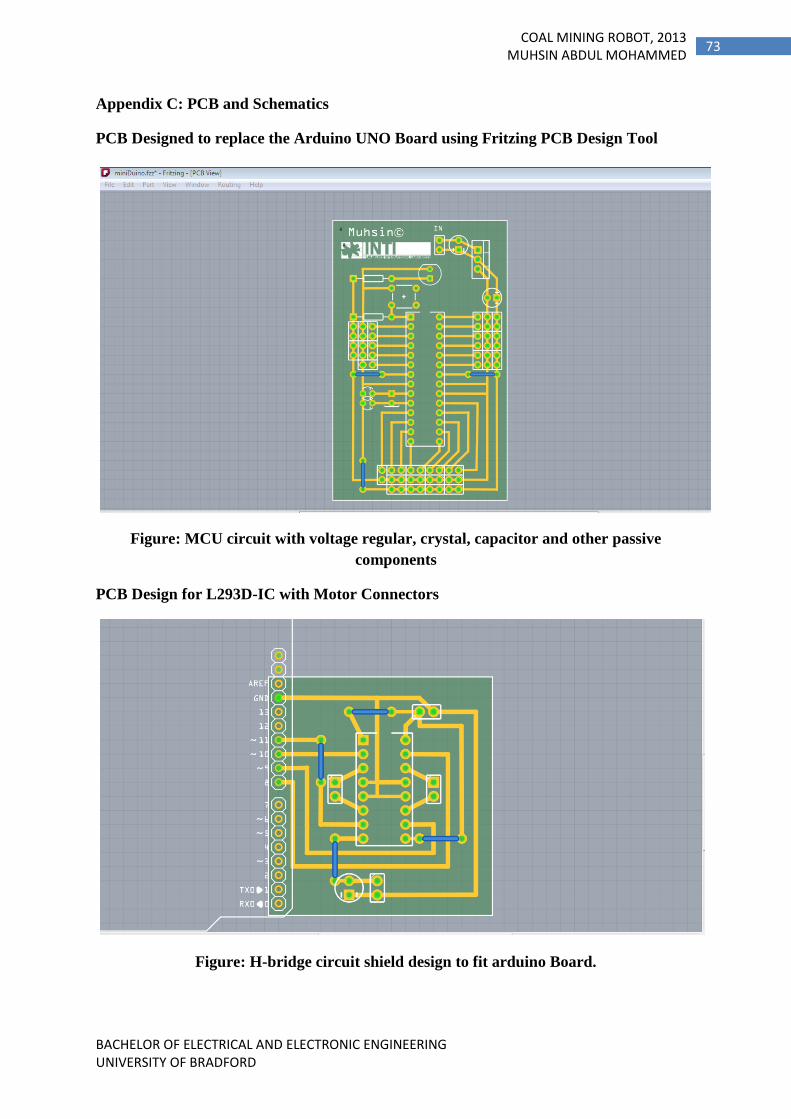
BACHELOR OF ELECTRICAL AND ELECTRONIC ENGINEERING UNIVERSITY OF BRADFORD
73 COAL MINING ROBOT, 2013
MUHSIN ABDUL MOHAMMED
Appendix C: PCB and Schematics
PCB Designed to replace the Arduino UNO Board using Fritzing PCB Design Tool
Figure: MCU circuit with voltage regular, crystal, capacitor and other passive
components
PCB Design for L293D-IC with Motor Connectors
Figure: H-bridge circuit shield design to fit arduino Board.

BACHELOR OF ELECTRICAL AND ELECTRONIC ENGINEERING UNIVERSITY OF BRADFORD
74 COAL MINING ROBOT, 2013
MUHSIN ABDUL MOHAMMED
Schematics of the L293D, Arduino and Temperature sensor connection.
Figure: Schematic connection of partial circuit

BACHELOR OF ELECTRICAL AND ELECTRONIC ENGINEERING UNIVERSITY OF BRADFORD
75 COAL MINING ROBOT, 2013
MUHSIN ABDUL MOHAMMED
Copper bottom circuit ready to Etch:
Figure: Circuit to place the Atmega328p board

BACHELOR OF ELECTRICAL AND ELECTRONIC ENGINEERING UNIVERSITY OF BRADFORD
76 COAL MINING ROBOT, 2013
MUHSIN ABDUL MOHAMMED
Figure: circuit for L293D IC and connectors to Atmega328p MCU
Appendix D: Pictures taken during the progress of project

BACHELOR OF ELECTRICAL AND ELECTRONIC ENGINEERING UNIVERSITY OF BRADFORD
77 COAL MINING ROBOT, 2013
MUHSIN ABDUL MOHAMMED
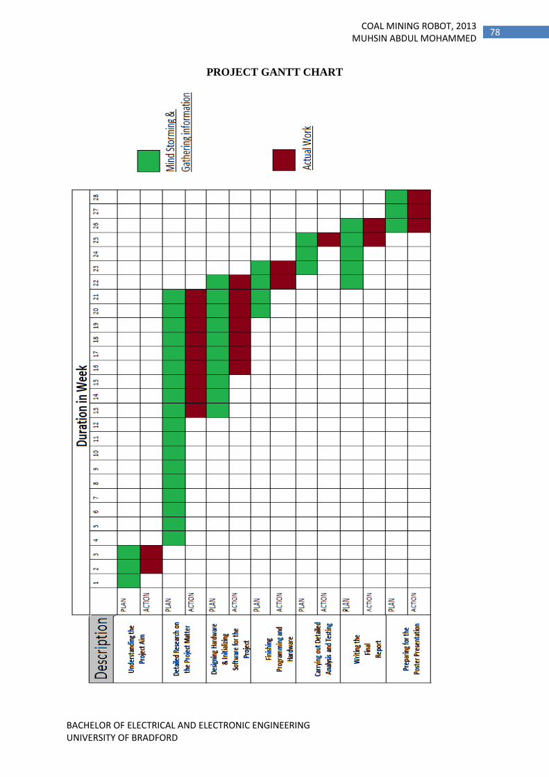
BACHELOR OF ELECTRICAL AND ELECTRONIC ENGINEERING UNIVERSITY OF BRADFORD
78 COAL MINING ROBOT, 2013
MUHSIN ABDUL MOHAMMED
PROJECT GANTT CHART