coaltech 2020 – dewatering and drying of fine coal to a
TRANSCRIPT

COALTECH 2020
Task 4.8.1
Dewatering and drying of fine coal to a
saleable product
by
P.E. Hand, Isandla Coal Consulting cc.
March 2000
Copyright COALTECH 2020 This document is for the use of COALTECH 2020 only, and may not be transmitted to any other party, in whole or in part, in any form without the written permission of COALTECH.

2
Table of contents
Index ........................................................................................................................................ 2
1 Foreword ........................................................................................................................... 8
2 Introduction ...................................................................................................................... 9
2.1 Definitions .................................................................................................................. 9
2.2 Problem statement ................................................................................................... 10
2.3 Basic Economics ...................................................................................................... 11
2.3.1 Arising Slimes .................................................................................................. 13
2.3.2 Existing Slimes ................................................................................................ 13
2.4 Purpose .................................................................................................................... 14
2.4.1 Clean coal......................................................................................................... 14
2.4.2 Discard ............................................................................................................. 15
2.5 Plant Moisture Balance ........................................................................................... 17
3 Survey of Dewatering and Drying Equipment ............................................................ 20
3.1 Mechanical ............................................................................................................... 21
3.1.1 Stockpiles (Solar drying) ................................................................................. 21
3.1.2 Screens ............................................................................................................. 21
3.1.2.1 Dewatering ................................................................................................... 21
3.1.2.2 Linear Screen ............................................................................................... 23
3.1.2.3 Pan Sep Screens ........................................................................................... 24
3.1.3 Thickening ....................................................................................................... 25
3.1.4 Centrifuges ....................................................................................................... 26
3.1.4.1 Screenbowl Centrifuge................................................................................. 26
3.1.4.2 Solidbowl Centrifuge ................................................................................... 29
3.1.4.3 Scroll Type Centrifuges ............................................................................... 30
3.1.4.4 Pusher Centrifuge......................................................................................... 32
3.1.4.5 Air Purged Basket Centrifuges .................................................................... 32
3.1.5 Filtration ........................................................................................................... 32

3
3.1.5.1 Filter cloth .................................................................................................... 32
3.1.5.2 Continuous Filters ........................................................................................ 33
3.1.5.2.1 Vacuum Drum Filter .............................................................................. 33
3.1.5.2.2 Vacuum Disc Filter ................................................................................ 34
3.1.5.2.3 Parnaby Type Belt Filter Press .............................................................. 35
3.1.5.2.4 Ceramec Filter ........................................................................................ 36
3.1.5.2.5 Horizontal Belt Filter ............................................................................. 37
3.1.5.2.6 Hyperbaric.............................................................................................. 39
3.1.5.3 Batch Filters ................................................................................................. 42
3.1.5.3.1 Filter Presses .......................................................................................... 42
3.1.5.3.2 Larox Filter ............................................................................................ 47
3.1.5.3.3 Bethlehem Tower Press ......................................................................... 49
3.1.5.3.4 Tube Press Filter .................................................................................... 50
3.2 Thermal Drying ........................................................................................................ 51
3.2.1 Direct................................................................................................................ 51
3.2.1.1 Rotary Driers ................................................................................................ 51
3.2.1.2 Fluidised Bed ............................................................................................... 53
3.2.1.3 Flash Dryer................................................................................................... 54
3.2.1.4 Pneumodrier ................................................................................................. 55
3.2.2 Indirect ............................................................................................................. 57
3.2.2.1 Holoflite ....................................................................................................... 57
3.2.2.2 Torus Disc .................................................................................................... 58
3.3 Other types ............................................................................................................... 59
3.3.1 Centridry .......................................................................................................... 59
3.3.2 EA Process ....................................................................................................... 61
3.3.3 Microwave ....................................................................................................... 61
3.3.4 Chemicals ......................................................................................................... 62
3.3.4.1 Super Absorbent Polymers .......................................................................... 62
3.3.4.2 Dewatering Chemicals ................................................................................. 62
3.3.4.3 Oil Agglomeration ....................................................................................... 63
3.3.5 Other Aspects ................................................................................................... 63
3.3.6 Summary of Costs ............................................................................................ 64
3.3.6.1 Mechanical Dewatering Cost Summary ...................................................... 64

4
3.3.6.2 Thermal Drying Cost Summary ................................................................... 65
4 South African Practice .................................................................................................. 66
4.1 Fine Coal Treatment ................................................................................................ 66
4.2 Ultrafine Treatment ................................................................................................. 67
4.2.1 Ingwe................................................................................................................ 67
4.2.1.1 Middelburg South ........................................................................................ 67
4.2.1.2 Rietspruit Colliery ........................................................................................ 68
4.2.1.3 Koornfontein Colliery .................................................................................. 68
4.2.2 Anglo Coal ....................................................................................................... 69
4.2.2.1 New Vaal Colliery ....................................................................................... 69
4.2.2.2 Kleinkopje .................................................................................................... 69
4.2.3 Sasol ................................................................................................................. 69
4.2.3.1 SSF Plants .................................................................................................... 69
4.2.3.2 Twistdraai .................................................................................................... 69
4.2.4 Duiker .............................................................................................................. 70
4.2.4.1 Atcom ........................................................................................................... 70
4.2.4.2 Arthur Taylor ............................................................................................... 70
4.2.4.3 Tselentis ....................................................................................................... 70
5 International Practice .................................................................................................... 71
5.1 Australia ................................................................................................................... 71
5.1.1 Burton Colliery & Moranbah North ................................................................ 72
5.1.2 Peak Downs ..................................................................................................... 73
5.1.3 Saraji ................................................................................................................ 73
5.1.4 Tailings Recovery ............................................................................................ 73
5.2 North America .......................................................................................................... 74
5.2.1 United Coal Company...................................................................................... 74
5.2.2 An Eastern US Coal Plant ................................................................................ 74
5.2.3 Lady Dunne ...................................................................................................... 74
5.3 UK ............................................................................................................................ 75
5.3.1 Gascoigne Wood .............................................................................................. 75
5.4 Germany ................................................................................................................... 75

5
5.4.1 Prosper Plant .................................................................................................... 76
5.5 Poland ...................................................................................................................... 77
5.6 China ........................................................................................................................ 77
5.7 India ......................................................................................................................... 77
6 Review of Research ........................................................................................................ 79
6.1 South Africa ............................................................................................................. 79
6.2 International ............................................................................................................ 79
6.2.1 Australia ........................................................................................................... 79
6.2.1.1 Coarse coal dewatering ................................................................................ 79
6.2.1.2 Super absorbent polymers ............................................................................ 80
6.2.1.3 Fundamentals of Fine Coal Dewatering ...................................................... 81
6.2.1.3.1 Abstract for Project C6049 .................................................................... 81
6.2.1.4 Improved dewatering in Fine Coal Centrifuges ........................................... 83
6.2.1.4.1 Abstract for Project 7039 ....................................................................... 83
6.2.1.4.2 Shear coagulation of Fine Coal to Improve Moisture Control .............. 83
6.2.1.4.3 Abstract for Project 4052 ....................................................................... 84
6.2.1.5 Advances in Coal Preparation Technology – Volume 3: Fine Coal and
tailings Dewatering Practice & performance ............................................................... 85
6.2.1.6 Air Purged Centrifuges ................................................................................ 87
6.2.2 U.K. .................................................................................................................. 87
6.2.3 USA.................................................................................................................. 87
6.2.3.1 Super absorbent polymers ............................................................................ 87
6.2.3.2 An Advanced Fine-Coal Dewatering Technique ......................................... 89
6.2.3.3 Granuflow Process ....................................................................................... 90
7 Techno-Economic Evaluation of Technologies ........................................................... 92
8 Conclusions ..................................................................................................................... 94
9 Acknowledgments .......................................................................................................... 95
10 Bibliography ............................................................................................................... 96

6
Figure 1 - Air Dry CV vs NCVAR .............................................................................. 11
Figure 2 - Differential Profit vs. CV ........................................................................... 12
Figure 3 - Effect of Moisture on Revenue per ton coal ............................................. 12
Figure 4 - Simplistic Economic Benefit of Flotation .................................................. 13
Figure 5 - Simplistic Economics of Existing Slimes .................................................. 14
Figure 6 - Slimes Dam at Middelburg Mine Services ............................................... 15
Figure 7 - Poorly Controlled Surface Slimes Dam .................................................... 16
Figure 8 - Filling In Pit Voids .................................................................................... 16
Figure 9 - Integrated Dump Method ......................................................................... 17
Figure 10 - Close up of Integrated Dump ................................................................. 17
Figure 11 - Product Moisture vs Ultrafines Moisture................................................. 19
Figure 12 Conventional Wisdom - Size, Moisture & Equipment ............................... 20
Figure 13 - Relative Costs of Dewatering & Drying (Ruonala 1998) ........................ 20
Figure 14 Dewatering Screen ................................................................................... 22
Figure 15 - Dewatering Screen Principles ................................................................ 22
Figure 16 - Linear Screen ......................................................................................... 23
Figure 17 - Pansep Screen ...................................................................................... 24
Figure 18 - Ultra High rate Thickener ....................................................................... 25
Figure 19 - Screenbowl Centrifuge ........................................................................... 26
Figure 20 - Solids Recovery & Moisture from Screenbowl Centrifuge ...................... 27
Figure 21 - Tungsten Carbide Screw........................................................................ 28
Figure 22 - Solidbowl centrifuge ............................................................................... 29
Figure 23 - CMI Scroll Centrifuge ............................................................................. 30
Figure 24 - Bird H900 Scroll Centrifuge .................................................................... 31
Figure 25 - Filter Cloth on Filter Press Plate ............................................................ 33
Figure 26 Disc Filter ................................................................................................. 34
Figure 27 Belt Filter Press ........................................................................................ 35
Figure 28 Ceramic Disc Filter ................................................................................... 37
Figure 29 Overhead view of a Horizontal Belt Filter Figure 30 Cutaway of a
Horizontal Belt Filter .......................................................................................... 38
Figure 31 Andritz Hyperbaric Filter, Dul Paskov Mine, Czechoslovakia ................... 40
Figure 32 Hyperbaric Filter Discharge Port .............................................................. 40
Figure 33 Hyperbaric Drum Filter ............................................................................. 41
Figure 34 - Overhead Beam Filter Press .................................................................. 42

7
Figure 35 _ Cake Formation in a Chamber Filter Press ........................................... 42
Figure 36 - Filter Press Filling .................................................................................. 43
Figure 37 - Core Blow & Wash Blow for Filter Press ................................................ 44
Figure 38 Typical Filter Press Control Circuit ........................................................... 45
Figure 39 Larox Filter Cutaway ................................................................................ 48
Figure 40 Larox Filter Belt Detail .............................................................................. 48
Figure 41 - Bethlehem Tower Press Figure 42 - Bethlehem Tower Press
Operational Cycle 49
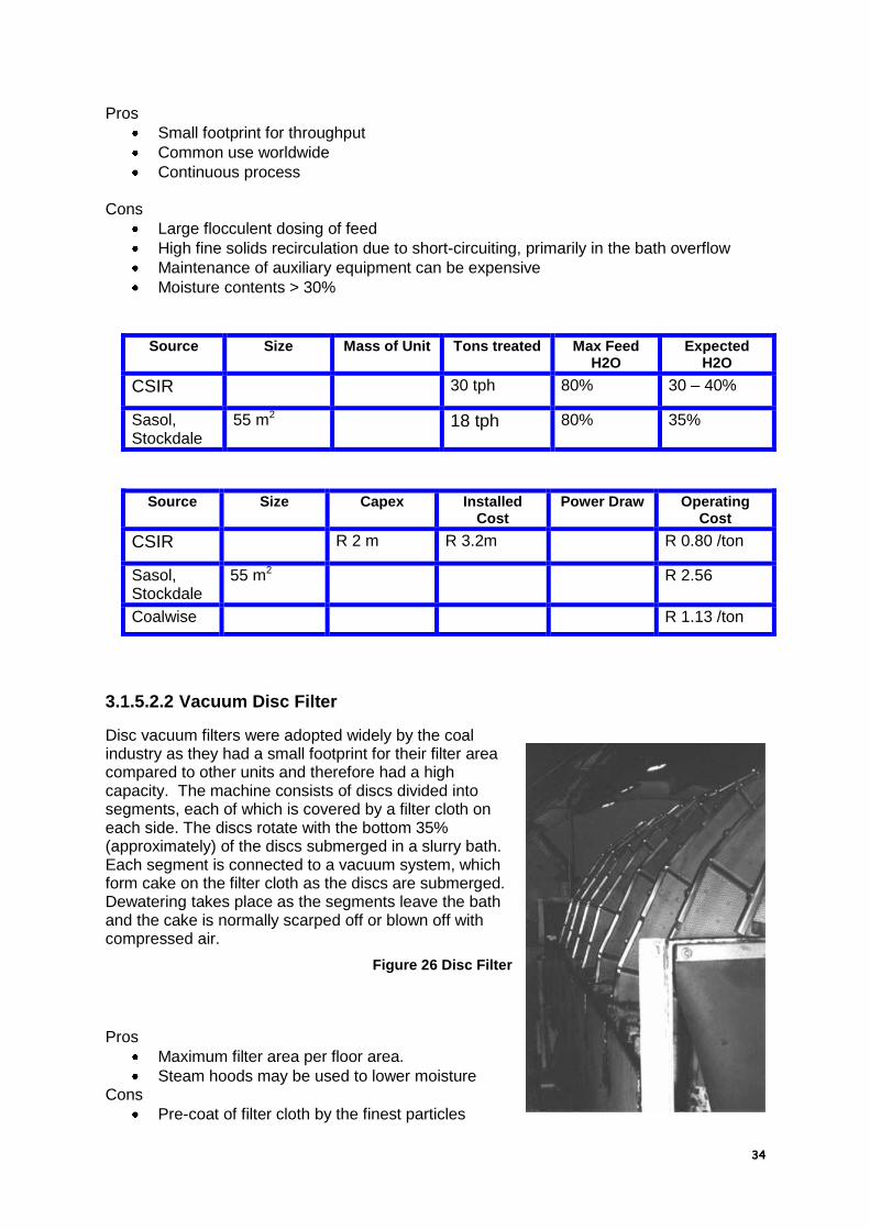
Figure 43 - Tube Press Discharge ........................................................................... 50
Figure 44 - Tube Press Cycle of Operation .............................................................. 50
Figure 45 - Ohio Valley Coal Thermal Dryer ............................................................ 52
Figure 46 - NFBC Fluidised Bed Boiler .................................................................... 53
Figure 47 - Flash Dryer Cutaway ............................................................................. 54
Figure 48 - Pneumodrier .......................................................................................... 55
Figure 49 - Pneumodrier Circuit ............................................................................... 56
Figure 50 - Holofilte Screw Cutaway ........................................................................ 57
Figure 51 - Svedala Holflite Dryer ............................................................................ 58
Figure 52 - Torbed Dryer .......................................................................................... 59
Figure 53 Humboldt Centridry .................................................................................. 60
Figure 54 - EA RF Assisted Dewatering ................................................................... 61
Figure 55 - RSA Coalfield ......................................................................................... 66
Figure 56 - Middelburg South Plant Flowsheet ........................................................ 67
Figure 57 - Shriver Filter Press at Middelburg South Plant ...................................... 68
Figure 58 - Burton Colliery Flotation & HBF ............................................................. 72
Figure 59 - Moranbah North Flowsheet .................................................................... 73
Figure 60 - Gascoigne Wood Flowsheet .................................................................. 75
Figure 61 - Prosper R&B Tailings Filter Presses ...................................................... 76
Figure 62 - Pilot Scale Superabsorbent Dewatering Process ................................... 81
Figure 63 - Residual Moisture of Fine Coal Using Superabsorbent Polymers .......... 81
Figure 64 - Mintek Process Cost Index .................................................................... 92
Figure 65 - limn Flowsheet for Dewatering Scenarios .............................................. 93

8
1 Foreword
This report has been written primarily as an extended literature search and incorporating operational experience for the Coaltech 2020 Coal Preparation Committee. As far as possible personal prejudices have been eliminated, with facts as offered by disparate sources being presented as far as possible. Efficient dewatering of coal is one of the highest priorities in production encountered by coal preparation engineers. The objective may be to meet product specification or environmental constraints. Reduction of fine coal moisture has become a major concern as the amount of fine coal increases, together with economic and environmental pressure to process it. To significantly improve dewatering performance, we need to understand the state of the art of coal dewatering practice.
Each piece of equipment has been costed where applicable. Where possible information sources have been crosschecked and each piece of equipment discussed with each supplier. Some equipment has not been costed, either because it is not seen as an individual process (e.g. air purging is an extra component not separately costed) or because it is new enough, that no costs are available. Costs presented are based as at February 2000 and as far as possible using current data. Where current costs are not available, past data has been updated using the Mintek process cost index, as explained in Section 7. These operating costs are given exclusive of cost of capital. The most important aspect of costing has unfortunately not been possible to include, which is laboratory testing of samples from each mine in order to give ranges of performance and costs for each piece of equipment. Possibly the collection of samples from various mines in the Witbank area should be tested for quality, particle size distribution and permeability at least, in a future Coaltech 2020 projects.

9
2 Introduction
The history of coal preparation has been the cleaning of successively finer fractions of the run of mine feed. Coarse coal has been washed alone for many years, with the duff being sold as a raw product. Indeed, even now destoning plants are used in some cases to produce coal for Eskom power stations. The coal industry has seen and continues to see increased competition and tighter product specifications while at the same time being faced with more onerous environmental standards. There are a number of factors that are making the fine cleaning of coal important :
More efficient mining techniques and ever higher tonnages tend to produce
finer raw coal being fed to coal plants.
It is both wasteful and environmentally costly not to treat the entire feed as full
mining and transportation costs have already been paid.
Discard dumps and slurry disposal in either expensive slurry dams or
underground is an additional expense.
In the past, environmental legislation has been such as to make disposable
cheap and permissible.
Recovering some of the ultrafines coal changes the mass balance of wastes
and makes co-disposal or integrated dumps possible.
Previously the recovery of fines and ultrafines was not deemed important, as overall mine costs were low. High cost producers worldwide usually used flotation. Competitiveness would seem to dictate that maximum yield must be made from mined coal.
Some areas of South Africa have been able to perform froth flotation down to zero for a number of years, normally for specific markets or where stockpiling can be undertaken to aid drainage. Only in the last ten years has Witbank coal being successfully treated by froth flotation, although it is still comparatively rare. Indeed, it is only in the last 15 years that spiral concentration of fine coal become commonplace. It may be controversial to say, but it is probably true, that the ease of marketing a coarser, drier coal has overshadowed the yield and economic benefits of washing the full range of coal and therefore only sporadic attempts have been made to overcome the problems associated with it. The benefit of total coal cleaning, which can only occur if the economics of dewatering and drying are advantageous, gives a benefit of increased revenues and decreased costs. Until an accepted economic method of dewatering coal is developed, then the separation techniques, which have been developed, will not be used to any great degree.
2.1 Definitions
It is important to define precisely what it is meant by the terms fines, ultrafines etc., many terms used in coal preparation are unclear, but in this report the following terms will apply:
10
Coarse coal, generally greater then 12 mm, being fed to a coarse washing
vessel.
Small coal, generally between 12 and 0.5 mm, being fed to a dense medium
cyclone.
Fine coal, generally less then 0.5 mm and greater than 150 microns and
treated, when applicable in a spiral concentrator.
Ultrafine coal, generally less than 150 microns, normally in the form of a
slurry, which is usually disposed of or that may be treatable by froth flotation.
This fraction is also sometimes referred to as slimes.
These definitions, certainly in terms of size, are not absolute, for example, fines and ultrafines may often be treated together or disposed of together.
2.2 Problem statement
The difficulty of dewatering increases as the diameter of the particle decreases, as the total surface area of the particles increases greatly (by the cube of the diameter) to which water can attach. Fine coal is far more difficult to dewater than coarse or small coal, because the surface area of the particle is significantly larger for the same tonnage. The tendency for water to be trapped on porous surfaces and between particles increases as the size of particles decreases. Water also has a greater difficulty in passing through the interstitial voids, when the particle diameter decreases. Coal particles vary widely in terms of size, shape and composition. A bed of coal slurry particles also consists of other species such as clays and shales. Generally, coarse coal is adequately dewatered using conventional screens and small coal is dewatered using conventional screens or basket centrifuges.
Water in coal can be considered a contaminant in the same manner as ash. It
reduces the effective heating value of coal, increases transport costs and can cause
difficulties in handling. Depending on the type of contracts there may be penalties
due to excess moisture and sometimes even rejection clauses. The plant moisture
balance is also important and water lost on the products must be replaced.
Fine coal dewatering should produce a product with as low a moisture content as the
selected equipment can produce. This should be done while also recovering a high
percentage of the feed, unless the poor quality of the finer coal dictates that it should
be discarded if possible.

11
2.3 Basic Economics
The revenue that can be attained by producing coal from flotation (or spiraling) is not a simple function of the heating value. Water with the coal will attract transport costs with no revenue. Coal price is normally determined on the basis of air dry calorific value with a tonnage adjustment to a predetermined moisture level or by applying a heat adjustment to the coal to determine the net calorific value of the coal, as shown in the graph below. The graph shows the relationship between air dry CV (calorific value) and NCVAR (net calorific value as received) for typical coal values. The second graph then shows the effect of moisture on revenue per ton on a purely heat adjusted basis. There is also a cost implication in transporting water. All these factors must be weighed up in determining revenue for the coal, which must then be weighed up against the cost of producing the coal.
NCVAR vc CV
5,600
5,800
6,000
6,200
6,400
6,600
6,800
7,000
25.00 26.00 27.00 28.00 29.00 30.00 31.00 32.00
CV Air Dry
NC
VA
R
H = 4%
IM=2.5%
TM = 7.5%
Figure 1 - Air Dry CV vs NCVAR
In general, the graph in Figure 2 holds true, that for each type of coal there is a
maximum profit that can be generated. In the case shown the maxima coincide at
27.6 ADCV for 4 products from different mines. In this case, an additional heat
adjustment (of 10%) has been included for coals above 6000 NCVAR. This type of
trend would be expected to continue for various moisture coals and financial
evaluations alluded to in Section 7 will determine the optimum quality to be produced
incorporating cost of equipment.

12
Adjusted for heat X 1.1 < 6000 & Ash
26 26.4 26.8 27.2 27.6 28 28.4 28.8
Dif
fere
nti
al P
rofi
t (R
an
ds)
Figure 2 - Differential Profit vs. CV
In many instances, coal worldwide is sold at high quality in order to make it easily
saleable, but this is at the expense of potential additional profit. Figure 3, gives an
indication of how moisture affects the Net As Received Calorific Value (NCVAR) of a
coal at a fixed air dry calorific value and how that relates to a price based on
NCVAR.
Total Moisture vs NCVAR & Price
5,700
5,800
5,900
6,000
6,100
6,200
6,300
6,400
5 5.4 5.8 6.2 6.6 7 7.4 7.8 8.2 8.6 9 9.4 9.8
Total moisture %
NC
VA
R
21.50
22.00
22.50
23.00
23.50
24.00
Pri
ce
per
ton
(h
eat
ad
jus
ted
)
NCVAR
Price
Figure 3 - Effect of Moisture on Revenue per ton coal

13
2.3.1 Arising Slimes
A simplistic calculation (which will be expanded upon) is used to illustrate the potential value of coal, which is presently (mostly) being discarded. Assume that 65 million tons of export coal is produced per annum.
At 65% yield ROM feed of 100 million tons per annum.
At 5% slimes 5 million tons ultrafines being discarded from coal plants each year.
At only 55% yield 2.75 million tons flotation product per year Assume dewatering to 20% moisture and a standalone product. Assume heat adjustment to pricing + a further discount if below 6000 NCVAR
Simplistic Determination of Flotation Benefit Per Annum
CV 28.00 NCVAR 5,263
TM 20.00 ARCV 23.09 5,515
IM 3.00 BDCV 28.87 6,894
H 4.00 GAD 6,688 12,038
GAR 5,515 9,928 gar btu
Heat Basis 6100
Heat adjustment 0.86
$ price per ton $23.00
Discount if below 6000 $1.00
Adjusted price $18.84
R/$ price 6.3
FOB Revenue R118.71
Transport + RBCT R60.00
FOR Revenue per ton R58.71
Flotation & drying costs R30.00
Profit per ton R28.71
Tons per annum 2750000
Total profit per annum R78,945,016
Figure 4 - Simplistic Economic Benefit of Flotation
Thus on the simplistic calculations above, by only dewatering to 20% and using conservative parameters an extra profit of R 80 millions per annum can be achieved. This disregards the costs of slurry disposal, 55% of which have now been avoided.
2.3.2 Existing Slimes
Slimes have been discarded over the years and an estimate is made here of the value of that coal. The calculations have been made only based on slimes produced in the act of producing coal exported through Richards Bay. This is probably reasonable, as the other

14
coals washed probably balances the slimes pumped underground, which would be extremely difficult to recover.
Profit per ton R28.71
Since 1976
Assume average tons per year to RBCT 32,000,000
Number of years 24
Average yield 60%
Total ROM tons to produce RBCT tons 1,280,000,000
% Slimes in feed 5.0%
Flotation yield 55.0%
Potential tons recoverable 35,200,000
Profit by recovering slimes dams R1,010,496,204
Figure 5 - Simplistic Economics of Existing Slimes
In summary, the table shows that there is a potential PROFIT of R 1 Billion rands
available by reprocessing existing slimes dams, to produce coal at a moisture of only
20%. This excludes the cost of forming those dams and possible future
environmental costs.
2.4 Purpose
2.4.1 Clean coal
The purpose of fine and ultrafine clean coal dewatering and drying can be summarised as:
To produce a handleable product for the market
To produce a product that will maximize revenues

15
To reduce the costs associated with disposal of untreated fines and ultrafines and to comply with future environmental regulations
To produce a product that will arrive at the customer with minimal moisture pick up.
To reduce the costs of transporting water and/or ash.
2.4.2 Discard
Presently, by far the majority of ultrafines are discarded. They are normally disposed of in a number of ways, each of which has their own associated costs and/or environmental problems associated with them. The methods of disposal include:
Pumping slurry underground o Pros
Out of sight, out of mind! Perception of cheap and easy Possible stabilisation of pillars
o Cons Difficult to recover the slimes at a later time Only possible for underground mines Problem with long pumping distances Cost of pumping Continuing supervision needed to ensure burning and seepage
problems are controlled
Building surface slimes dams
Figure 6 - Slimes Dam at Middelburg Mine Services
o Pros
Easily supervised Slimes can be recovered later
o Cons
Cost, large dams can cost up to R 10 million each

16
Supervision must be regular to ensure control of dams, no “breakouts”, spontaneous combustion etc.
Will these have to be reprocessed later for environmental reasons? Cost of final rehabilitation.
Figure 7 - Poorly Controlled Surface Slimes Dam
Pumping into final voids o Pros
Convenient in opencast mines Relatively inexpensive
o Cons Potential problems with contamination of the water table Difficulty of recovering water Difficult to recover the slimes at a later point
Figure 8 - Filling In Pit Voids
Filtration for sale to local low quality coal consumers such as Eskom o Pros

17
Revenue stream from “waste” material No disposal costs or environmental concerns
o Cons Capital cost of the equipment Potentially higher revenues from a beneficiated product
Co-disposal of coal with coarse discard coal o Pros
Up front design must be correct Discard dump is rendered totally benign
o Cons Normally the slimes percentage is too high for the quantity of coarse
discard Difficult to recover the slimes at a later point
Integrated disposal of slimes and coarser discards. o Pros
Produces extremely stable, impermeable discard dumps Water is recovered Relatively cheap
o Cons Difficult to recover the slimes at a later point (if raw slimes are used)
Figure 9 - Integrated Dump Method
Figure 10 - Close up of Integrated Dump
2.5 Plant Moisture Balance
There are two ways of addressing flotation products: standalone or adding to the
coal produced in the rest of the coal plant. This can have a significant effect in
that a standalone product will have to be made as dry as conventional coal and

18
handleable. This implies thermal drying to achieve low enough moisture and a
pelletising or briquetting step in order to produce a handleable product.
Adding flotation product to the total coal may allow that portion to be slightly
higher in moisture and for the naturally arising size range to be tolerated. There
are some areas to be addressed, such as:
Will fine coal blow away?
Will fine coal reabsorb moisture?
These issues are being investigated by other Coaltech 2020 groups.
A further question is the level of moisture in coal that is deemed saleable by other
coal producing countries such as Australia, who are happy to use horizontal belt
filters producing flotation products at moistures of approximately 30%.
A typical distribution of moisture in coal is shown in the table below.
Feed Yield Total Moisture
Water Distribution
Coarse 60 65.0% 39 5 40.1%
Small 28 65.0% 18.2 9 33.7%
Fine 8 60.0% 4.8 13 12.8%
Ultrafine 4 60.0% 2.4 27 13.3%
Total 100 64.4 7.5 100.0%
It may be noted that the total moisture without the flotation fraction would be 6.8%. The numbers used are based on widely quoted moistures expected from coarse, small and fine sections of 5, 9 and 13% respectively. However, the actual average plant produces moistures significantly higher than 6.8%. Where is the source of the higher moisture? If this was found and the moistures reduced in the “easily dried” fractions then flotation product may be added back with no higher overall moisture. An obvious example is the common use of dewatering screens to dry spiral product. This normally produces a moisture of about 30% and is used because it is cheap in terms of capital and operating costs. However, the excess moisture that it produces may make it expensive in practice. It also means that replacing a dewatering screen with another piece, or pieces, of equipment, which can dewater flotation and spiral products to a lower overall moisture will probably increase yield and therefore be better economics even though the costs are ostensibly higher. The table shows that even at a moisture of 27%, the percentage of the water in the ultrafines portion compared to the total water in the product is only 13%. It also shows that at the “advertised” moistures for each size range, then a relatively simply dewatered flotation product at 27% would produce an overall moisture of 7.5%, which is closer to the actual colliery produced moistures. Is potential yield from flotation being lost because the existing dewatering equipment is not working correctly?

19
This will be further investigated later in the sections on coarse coal dewatering and chemical dewatering. These aim at the coarse and small coal, where a small reduction in moisture on a larger amount of material will reduce the overall moisture considerably and could prove simpler to do than dewatering fines and ultrafines. A case in point is that of Rietspruit, the only plant that uses flotation to recover all its ultrafine coal, has not increased overall moisture compared to before flotation. This may be due to the addition of dewatering chemicals to the small coal. If this is the case, then concentrating on improving dewatering of larger coal may allow relatively cheap flotation dewatering to be used. The other possible reason for the overall moisture staying the same is that of increased attention to the performance of the dewatering equipment (see later in the screenbowl section concerning tungsten carbide baskets).
Product Moisture vs Ultrafines Moisture
5.50
6.00
6.50
7.00
7.50
8.00
0 3 6 9 12 15 18 21 24 27 30 33
Ultrafines moisture
Pro
du
ct
Mo
istu
re
Smalls 9%, Coarse 5% Smalls 8%, Coarse 5%
Smalls 9%, Coarse 4.5% Smalls 8%, Coarse 4.5%
Figure 11 - Product Moisture vs Ultrafines Moisture
The graph illustrates what the effect on total product moisture of the moisture of the
ultrafines fraction. The various lines show what is possible depending upon the
various levels of coarse and small moistures.

20
3 Survey of Dewatering and Drying Equipment
This section will be used to describe as many pieces of dewatering equipment as possible or reasonable. Some equipment is extremely well known and others are rare and/or esoteric. It is not the intention of this report to explain each process in detail, as such details are widely available. Explanations are given in order to explain differences between techniques and their viability or otherwise as dewatering or drying processes.
Figure 12 Conventional Wisdom - Size, Moisture & Equipment
The graph above is the “common wisdom” regarding which dewatering equipment can be used on each size range. It also estimates what moisture can be expected from the equipment and size combinations. There are challenges within such a diagram.
Figure 13 - Relative Costs of Dewatering & Drying (Ruonala 1998)

21
The graph above illustrates the general principle that mechanical dewatering is considerably cheaper than thermal drying coal, but thermal drying can produce low moistures.
3.1 Mechanical
3.1.1 Stockpiles (Solar drying)
Little work has been carried out on the effect of leaving coal out to dry in the sun and less on building covered areas sufficiently large enough to accommodate coal produced from a coal plant and left to dry before loading out onto trains. A porous bed, through which a slight vacuum was passed, was advertised at one stage, but this was small scale and is now not available, as far as the author is aware. The only work on stockpile drainage, in South Africa, was carried out in conjunction with the Randcoal Coal Oil Flotation testwork, which showed that flotation product could be dried to 15% moisture in 3 days with turning twice per day. Screenbowl product dried in paddocks had an ultimate moisture 2% lower than just slurry and was quicker to get to ultimate moisture. The main problem is that of continuous management and, of course, rain. Capital costs are also not that low as pad preparation is required (not insignificant as thin layers are required) as well as various front end loaders and other mobile equipment.
3.1.2 Screens
3.1.2.1 Dewatering
High frequency dewatering screens are probably the most common dewatering
technique for raw fine coal or spiral product, as they are generally simple, cheap and
robust. Generally, moistures of 30% plus can be expected on –1mm + 0.2 mm
material.

22
Figure 14 Dewatering Screen
The screen incorporates a 45 sloping back deck, fitted with cross flow slotted
apertures, incoming slurry is fed across the back of this deck. The main deck of the
screen slopes upwards at 5 , slurry pools at the lowest point of the screen and solid
particles bridge over the apertures and forms a cake. The cake then forms a filtration
bed, which allows very fine particles and water through. The vibration moves the
cake up the screen, where further dewatering takes place until it is discharged at the
lip.
Figure 15 - Dewatering Screen Principles
Pros
Cheap and simple
Simple installation and low maintenance

23
Cons
Produces high cake moistures, in excess of 30%
Underflow contains large amounts of solids
Source Size Mass of Unit Tons treated Max Feed H2O
Expected H2O
CSIR 35 tph 30%
Velmet 1.2m wide 1.8 tons 25 tph 60% 30 - 35%
Velmet 1.5m wide 2.6 tons 35 tph 60% 30 - 35%
Velmet 1.8m wide 3.4 tons 55 tph 60% 30 – 35%
Source Size Capex Installed Cost
Power Draw Operating Cost
CSIR R 0.10 /ton
Velmet 1.2m wide R 68500 R 82000 8 kw R 0.10 /ton
Velmet 1.5m wide R 107300 R 120000 10 kw R 0.10 /ton
Velmet 1.8m wide R 122900 R 145000 10 kw R 0.10 /ton
Coalwise R 0.11 /ton
3.1.2.2 Linear Screen
The linear screen is only included in this report for the sake of completeness, as it is possible that this type of screen may be used as drain & rinse screens in fine coal dense medium circuits. This may or may not mean that these screens will then be expected to perform double duty on dewatering or more probably to provide a feed to another dewatering device. Sizing is an issue, whereby the primary job of this equipment is to classify and it is important in dewatering that sprays are not situated too near the end of the screen.
Figure 16 - Linear Screen

24
Pros
No vibration, silent, small unit
High availability, low power
Potential use in Fine coal DMS plants as D&R Cons
Primarily a classifying screen and not presently used as a dewatering screen on coal.
Large footprint for capacity.
3.1.2.3 Pan Sep Screens
The Pan Sep screen is similar to the Linear screen and included for the same reasons. The Pan Sep is unique in that it can be fed on its top and bottom side, reducing the floor area needed for the same tons per hour feed.
Figure 17 - Pansep Screen
Pros
No vibration, small unit
High availability, low power
Potential use in Fine coal DMS plants as D&R
Minimal cloth stretch
Silent Cons
Primarily a classifying screen and not presently used as a dewatering screen on coal.
Large footprint for capacity. Pan Sep is also working on a new type of filtration using the pan sep as a basis but using compressed air to provide a vacuum via a venturi. It is estimated to treat 25 tph and cost R 700000.

25
3.1.3 Thickening
While not strictly a complete dewatering process, thickeners play an important role in
almost all coal preparation plants. They generally treat minus 150 micron material for
disposal and recover water to be quickly recycled back to a plant. Flocculation is
usually required to reduce the capital costs of the thickener.
There is scope in the future for cheap, high efficiency thickening to thicken feed
before dewatering in other devices. This is critical in feeding screenbowl centrifuges
(which will be discussed), otherwise ultrafine particles will “pour” straight through the
basket section. This same application has also been investigated prior to horizontal
belt filters. The overall cost of dewatering may be reduced by using thickeners to
reduce the volumetric load to other equipment, which reduces the required size of
the more expensive equipment.
Figure 18 - Ultra High rate Thickener
In conventional use, they generally dewater
either raw coal or flotation discard material prior
to disposal. There has been a resurgence of
interest in using ultra high rate thickeners
(previously known as deep cones in British
Coal) to produce either handleable underflow
for disposal by conveyor or to thicken the feed
to a screenbowl centrifuge, to reduce liquid
volume and reduce screenbowl losses in a
reasonably cheap piece of equipment.
The important requirements for a thickener are:
Recycling of process water, minimizing make up costs
Reduction in plant effluent
Reduction in size of tailings ponds or alternate disposal methods
Cost effective thickening
Controlled high density underflow for feed to other dewatering units

26
3.1.4 Centrifuges
The majority of small coal, 12 to 0.5 mm, is dewatered using vibrating screens to approximately 20% moisture, and then further dewatered in vibrating basket centrifuges. The final product moisture should then be less than 10%. These centrifuges are very familiar and relatively cheap to buy and operate. However, the basket apertures will usually be 0.3 mm and are therefore not suitable for dewatering finer coal. A number of machines based on the same principle, but applying higher g in order to remove more water have been developed to treat the finer coals.
3.1.4.1 Screenbowl Centrifuge
A screenbowl centrifuge is a continuous discharge two stage unit that combines a solid bowl clarifier with a centrifugal filtration section. Feed slurry is introduced into the machine, accelerated in a chamber up to full rotational speed, and then distributed via feed ports into the solid bowl section. Large, dense particles settle against the wall with the liquid migrating to the axis of rotation. A helical screw operating at a slightly slower speed then moves the solids towards the screen section. The solids emerge up the beach and the clarified liquid overflows at the effluent end of the machine. The solids pass to a screen section where additional moisture is spun out of the solids and the liquid passes through the screen section. The dewatered cake is then discharged from the end of the screen section.
Figure 19 - Screenbowl Centrifuge
A major issue in the use of screenbowl centrifuges is that of solids loss through the basket. The graph below indicates the amount of loss expected depending on the amount of ultrafines in the centrifuge feed. A critical element, not shown on the graph, is the percentage solids of the screenbowl feed and the UK practice of thickening feed should be investigated. This configuration is being installed at Koornfontein and will be operational before mid year. Another area for research (described later) is the treatment of feed with chemicals or oil in order to improve dewatering.

27
Figure 20 - Solids Recovery & Moisture from Screenbowl Centrifuge
A formula for the calculation of surface moisture produced by a screenbowl centrifuge has been developed by Prof. Batel. This formula should be used just as a guide as many factors such as feed % solids are not incorporated within it.
%H2O = SGL / SGC . (K1 (O’K . SGC)/(Z . d1))0.25 Where : SGL = SG of liquid SGC = SG of coal K1 = Constant from Batel, coal = 3340 O’K = Mean surface area in cm2/g D1 = Mean particle diameter in cm
Z = Centrifugal force in m/s2 = (r . 2 . n2)/(900 . g) = r . n2 /900
R = Internal radius of bowl in m
N = Rotational speed of bowl in rpm
A conventional screenbowl centrifuge, in South Africa, uses a ceramic basket with apertures of 2-3mm and can achieve a cutpoint in the order of 20 microns under ideal conditions. In practice, the ceramics are easily broken, particularly if there is no guard screen in front of the centrifuge. Broken ceramics are normally plugged to prevent loss of solids to the underflow, which reduces the available open area for drainage, in some cases by up to 30%. In addition, the ceramic edges often smear which reduces the cutpoint accuracy. It is common practice in the US to use tungsten carbide screws instead of ceramic to maximise performance and increase life. Rietspruit Colliery has five screenbowls, of which three have been converted to tungsten carbide screws and their life so far is at 20000 hours, compared to the usual life of 10000 hours between overhauls. It is expected that at least 30000 hours will be achieved, which will make the price premium of 67% more expensive than a ceramic screw a viable proposition, especially considering that all of the potential open area is available through its whole life. The apertures can also be made far finer, in the order of 0.8mm, which will reduce solid losses in the centrate.

28
Figure 21 - Tungsten Carbide Screw
Pros
Well known dewatering unit
Continuous process
Compact units
Commonly used worldwide to dewater down to zero.
Spiral moistures down to 12%
Flotation and spiral product moistures down to 17% Cons
Lack of competition in RSA makes screenbowls expensive
Probably needs pre-thickening to dewater down to zero.
System approach needed to ensure minimal solids losses in the filtrate
Source Size Mass of Unit Tons treated Max Feed H2O
Expected H2O
Anon 1100 x 3.3 23 tons 50 50 14% fines 18% f + u
Baker
Process
1100 x 3.3 23 tons 50 50 12–15% fins 17% f+u
Enertek 2x900x 3.3 38 tons 60% 50% 22% f + u
Size Capex Installed Cost Power Draw Operating Cost
Anon 1100 x 3.3 R 1.8 m R 3.1 m R 1.60 / ton
Baker
Process
1100 x 3.3 R 1.7 m R 2.7 m 125 kW Mech 97c/t Power 60c/t
Baker 1100 x 3.3 R 2.4 m R 3.8 m 125 kW Mech 65c/t Power 60c/t

29
Process
Enertek 2 x900 x
3.3
R 6.98 m R 11.05 m 170 kW R 1.00 /ton
Koornfontein 1100 x 3.3 125 kW R 1.71 /ton
Coalwise R 1.26 /ton
3.1.4.2 Solidbowl Centrifuge
Solidbowl centrifuges are continuous machines, which use flocculent in order to assist in producing clear centrate, which is usually the priority from these machines. They are essentially a screenbowl centrifuge without the screen section, thus all the separation is done by high centrifugal forces forcing particles to the wall and the centrate migrating to the axis of rotation. They are not particularly suitable for dewatering products as moistures are in excess of 30% and sometimes the resulting cake can be unhandleable. In the UK, solidbowl products tend to be stabilized with cement before disposal. Only a few solidbowl centrifuges have been used on South African coal. The units at Middelburg Mine Services and Van Dyks Drif were very short lived and removed due to their high flocculent consumption, often sloppy, unhandleable cake and often dirty filtrate.
Figure 22 - Solidbowl centrifuge
Pros
Relatively small units
Greater pressure drop than screenbowl centrifuges. Cons
High moisture product, > 30%, sometimes unhandleable
Uses large amounts of flocculent
Dirty filtrate possible
Size Mass of Unit Tons treated Max Feed H2O
Expected H2O

30
Anon 1100 x
2.7
25 tons 50 tph 50% 25 – 30%
Baker
Process
1100 x
2.7
25 tons 50 tph 50% 25 – 30%
CSIR 30 tph 30 – 40%
Size Capex Installed Cost
Power Draw Operating Cost
Anon 1100 x 2.7 R 1.6 m R 2.7 m R 2.40 /ton
Baker
Process
1100 x 2.7 R 1.6 m R 2.6 m 125 kW R 2.20 c/t
CSIR R 2.0 m R 3.0 m R 2 /ton
Coalwise R 4.10
3.1.4.3 Scroll Type Centrifuges
A modification of the standard basket centrifuges used on small coal is that of scroll type centrifuges. They come in two forms, horizontally mounted as per the H 900 shown and the vertically mounted as per the CMI centrifuge shown. Curved scraper blades are mounted in a helical pattern which run in the same direction as the basket but run at a slightly different speed, developed by a dual speed planetary gearbox, so that the scraper conveys the coal down the basket which enhances the basket loading and the retention time. This type of machine normally runs at a high g between 200 and 400.
Figure 23 - CMI Scroll Centrifuge
Scroll centrifuges work on particles from 12mm to 100 microns, with a feed concentration of 30 to 65%. These machines seem to have become the latest standard for treating spiral concentrates.

31
Figure 24 - Bird H900 Scroll Centrifuge
Pros
Relatively low cost
Bottom size of 100 microns
Large user base worldwide
Small footprint and simple installation Cons
High solids losses in centrate
High wear in expensive scroll component
Size Mass of Unit Tons treated Max Feed H2O Expected H2O
H900EBW 36 4.5 tons 30 tph fines 50% 12 –14%
H900EBW 42 7.3 tons 60 tph fines 50% 12 – 14%
FC 1200 Birtley
5.65 tons 50 tph 12 – 14%
Size Capex Installed Cost Power Draw Operating Cost
EBW36 R 0.45 m R 0.65 R 1.20 /ton
EBW42 R 0.65 m R 0.8 R 1.20/ton
Koornfontein Wemco H900
R 0.87 / ton
FC 1200 Birtley
R 0.65 m R 0.8 m R 0.25 /ton
Coalwise R 0.85 /ton

32
3.1.4.4 Pusher Centrifuge
This is an extremely rare piece of equipment in South Africa. Its principal use is in the food industry. It consists of a ceramic lined basket and a pusher plate that rotates with the centrifuge shaft and moves back and forth, pushing the solids towards the discharge. It was tested in 1984 by Sulzer Africa at Kleinkopje Colliery, the testwork was suspended due to the fragility of the ceramic components impacting coal and various contaminants at high speed. Pros
Similar or lower moistures than screenbowl centrifuges Cons
Fragile ceramics
3.1.4.5 Air Purged Basket Centrifuges
Minimal work has been done on applying air into the basket of a fine coal centrifuge
(or indeed into the basket of a small coal centrifuge). It has been shown to have
promise, reducing expected moistures by approximately 1%. The work done in
Australia is shown in the relevant section. Some informal work was done at
Rietspruit using a blower and water spray nozzles and was found to reduce basket
centrifuge moistures by 1%.
3.1.5 Filtration
Filtration is the separation of solid from liquid obtained by passing slurry through a permeable membrane, which allows the majority of water to pass while retaining most of the solids. To get the fluid to pass through the membrane, a pressure differential must be applied, and this is done by either gravity, vacuum, pressure or some combination of these. Filtration can be split into the two wide areas of continuous and batch type. All filtration consists of the following processes:
Cake formation – slurry particles hit the filter cloth and gradually build up a cake and the water passes through the cake.
Cake desaturation – water and air pass through the cake, moisture falls and eventually air passes through the cake and cloth.
Cake discharge – filter cake is removed from the device
Belt washing – water is sprayed onto the cloth to remove fines build up and to unblock cloth pores.
3.1.5.1 Filter cloth
A common feature of almost all filters is the filter cloth. This is a huge subject, which can only be briefly discussed here. Generally,
the finer the cloth, the more impermeable it becomes.

33
A balance has to be struck between water passage through the cloth and acceptable amounts of solids in the filtrate.
Most solids should be removed in one pass, otherwise a large solids load in the recycle can develop.
Too fine a filter media, results in a large pressure drop across a thin layer and subsequent low filtration rates with high cake moistures.
Figure 25 - Filter Cloth on Filter Press Plate
3.1.5.2 Continuous Filters
Continuous filtration, as the name suggests is a method of continually introducing slurry to be dewatered to a filter cloth while continually removing the cake and filtrate separately.
3.1.5.2.1 Vacuum Drum Filter
Vacuum drum filters have been used for many years in coal preparation around the world. They consist of a cylindrical drum mounted on a shaft, which rotates through a bath of agitated slurry. A vacuum is applied from the inside of the drum beginning at the point at which the drum enters the slurry and pulls the filtrate through the filter cloth and cake formation occurs. The cake is lifted out of the bath and the vacuum then removes more water from the formed cake. At the discharge point, an airblow is used to discharge the cake. The cloth it is generally washed with sprays before rejoining the drum for a further cycle. The drum filter generally occupies a relatively small footprint for its tonnage capacity and is able to tolerate changing feed conditions due to the slurry bath. It is important that the slurry bath is continually agitated as the vacuum is pulling the particles to the cloth against gravity. The submerged portion of the drum is approximately 35% of its total area and the drying section approximately 45%. The final moisture content of the cake is dependent on the feed and throughput, but is generally in the order of 30%. Filter aids are sometimes used to increase throughput and decrease moisture. Generally, these units are fairly easy to maintain. They are sometimes used with a steam hood to further reduce moisture.
34
Pros
Small footprint for throughput
Common use worldwide
Continuous process
Cons
Large flocculent dosing of feed
High fine solids recirculation due to short-circuiting, primarily in the bath overflow
Maintenance of auxiliary equipment can be expensive
Moisture contents > 30%
Source Size Mass of Unit Tons treated Max Feed H2O
Expected H2O
CSIR 30 tph 80% 30 – 40%
Sasol, Stockdale
55 m2 18 tph 80% 35%
Source Size Capex Installed Cost
Power Draw Operating Cost
CSIR R 2 m R 3.2m R 0.80 /ton
Sasol, Stockdale
55 m2 R 2.56
Coalwise R 1.13 /ton
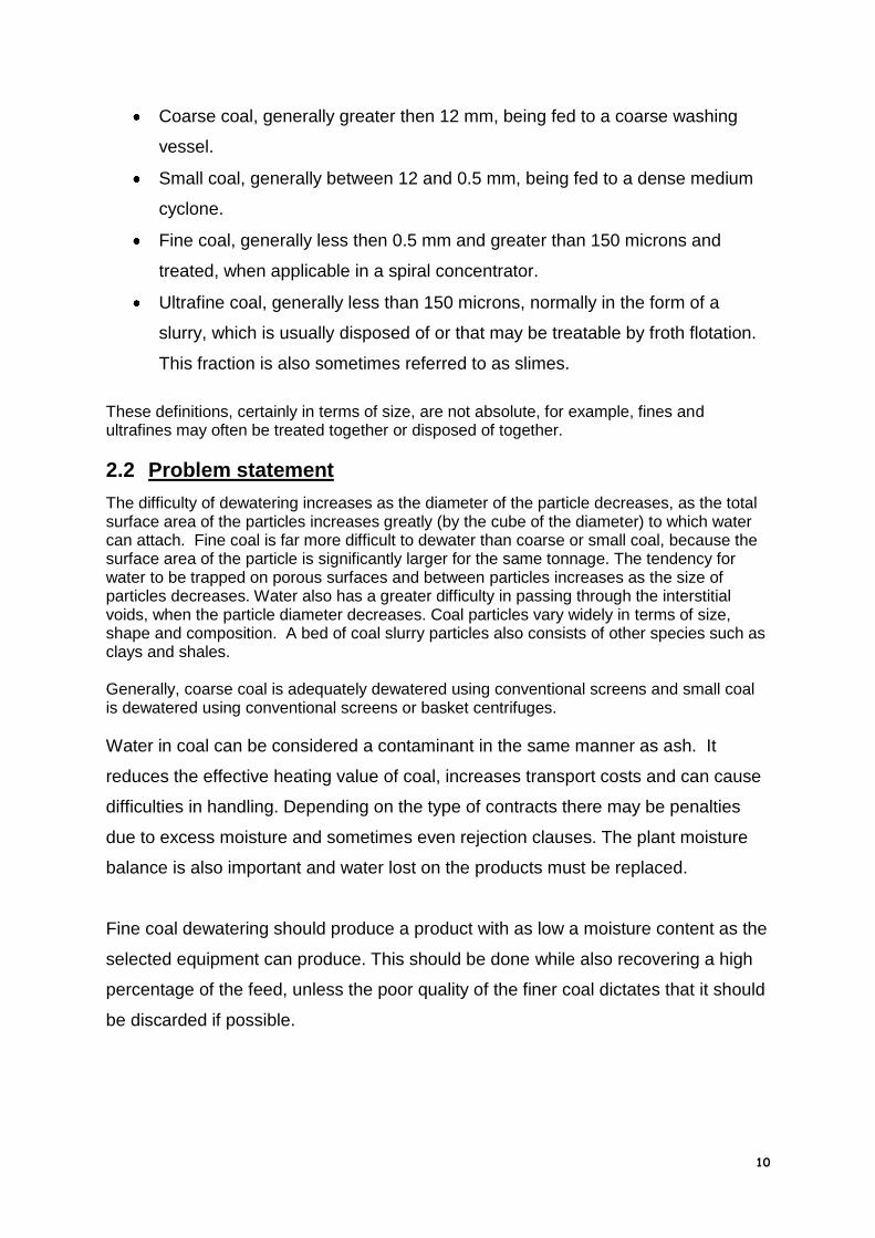
3.1.5.2.2 Vacuum Disc Filter
Disc vacuum filters were adopted widely by the coal industry as they had a small footprint for their filter area compared to other units and therefore had a high capacity. The machine consists of discs divided into segments, each of which is covered by a filter cloth on each side. The discs rotate with the bottom 35% (approximately) of the discs submerged in a slurry bath. Each segment is connected to a vacuum system, which form cake on the filter cloth as the discs are submerged. Dewatering takes place as the segments leave the bath and the cake is normally scarped off or blown off with compressed air.
Figure 26 Disc Filter
Pros
Maximum filter area per floor area.
Steam hoods may be used to lower moisture Cons
Pre-coat of filter cloth by the finest particles

35
Vacuum energy is partially used to suck the particles and water to the filter
Cracking of the cake destroys the vacuum
Recirculation of fine coal particles
High flocculent dosing of feed
Source Size Mass of Unit Tons treated Max Feed H2O
Expected H2O
CSIR 30 tph 80% 30 – 40%
Sasol, 168 m2 72 tph 80% 35%
Source Size Capex Installed Cost
Power Draw Operating Cost
CSIR R 1.5 m R 2.4m R 0.90 /ton
Sasol, Dorr Oliver
232 m2 R 2.49 /ton
Sasol, Krauss Maffei
168 m2 R 2.37 /ton
Coalwise R 1.22 /ton
3.1.5.2.3 Parnaby Type Belt Filter Press
This type of filter has been widely used over the years and in various countries. They consist of two filter cloths between which the slurry to be filtered is placed. The cloths travel through a series of rollers with increasingly smaller diameters, which squeeze the cloths together and force water through the cloths. They are common in the USA on flotation discards. They were last used in South Africa at Elandsfontein Colliery on thickener underflow. Its use was discontinued due to the high cost of filter cloths for the machine (approx. R 20000 per cloth in 1997 terms) and the difficulty in cloth tracking, which increased cloth consumption.
Figure 27 Belt Filter Press

36
Pros
Tends to produce a handleable cake
Continuous process
Visible operation
Commonly used worldwide, particularly on tailings Cons
High flocculent consumption
Mechanically complicated
Expensive (continuous) cloths
Fully imported
Difficult to control, manual operation
Feed must be typically thickener underflow solids concentration
Source Size Mass of Unit Tons treated Max Feed H2O
Expected H2O
Anon 3m wide 40 tph 50% 30 – 35%
CSIR 30 tph 50% 35%
Source Size Capex Installed Cost
Power Draw Operating Cost
CSIR R 2.5 m R 2.0 /ton
Anon R 1.4 m R 2.2 m R 4.50 /ton
Coalwise R 5.90 /ton
3.1.5.2.4 Ceramec Filter
A ceramic filter is an extremely interesting piece of equipment as it performs as a vacuum filter by using sintered aluminium membranes with uniform micropores to create a capillary action. The microporous filter media allows the water through with a guaranteed filtrate of 50 ppm, due to the effective capillary size of 2.3 microns. In outward appearance the ceramec filter is similar to a disc filter with discs immersed in the slurry bath. A pressure differential aided by a small vacuum pump causes cake to form on the surface of the discs and dewatering takes place while free moisture is available, even when unsubmerged and filter cracks do not affect performance. Cake is removed by scrapers and the discs cleaned ultrasonically.

37
Figure 28 Ceramic Disc Filter
Pros
Lower moistures than conventional vacuum filtration
Only a small vacuum pump is required.
Low energy consumption, up to 90% less than conventional disc filters
High availability
Low operating costs due to low energy requirement and no cloths
Small footprint
Clean filtrate Cons
Each unit is low in capacity, multiple units are required for reasonable tonnage
Very high capital cost
Not used on coal so far.
Source Size Mass of Unit Tons treated Max Feed H2O
Expected H2O
Outokumpu 8 x CC45 110 tons 50 tph 75% 18%
Enertek 6 units 60 tph 60% 7%
Source Size Capex Installed Cost
Power Draw Operating Cost
Outokumpu 8 x CC45 R 34 m R 45 m 216 kW tot R 0.80 /ton
Enertek 6 units R 24.9 m 840 kW R 3.35
3.1.5.2.5 Horizontal Belt Filter
The use of Horizontal Belt Filters (HBF) is probably the piece of equipment whose use in coal is increasing worldwide the most and particularly in Australia. Rotary disc filters, common in the coal industry, have problems (as previously outlined) of poor performance, fine coal recirculation etc. The HBF was designed to address these

38
problems, even while increasing the footprint massively and increasing capital costs. They were first used in the 1930’s to dewater chemicals and minerals, but were updated using new materials in the 1980’s.
Figure 29 Overhead view of a Horizontal Belt Filter Figure 30 Cutaway of a Horizontal Belt Filter
Almost every piece of new dewatering equipment installed in Australian coal plants over the last 10 years has been an HBF. The HBF is simply a filtration area laid out flat with the vacuum box underneath. Slurry is fed by gravity at one end and the belt draws it over the vacuum box where filtrate is removed. An endless carrier belt covered with an endless filter cloth is used which is carried by an air cushion. The belt is washed on each cycle, which aids cloth life and performance. The carrier belt has a flexible rubber skirting which forms a tray, which retains the slurry and cake. The effect of being fed by gravity is that a differential sizing takes place whereby coarse particles preferentially fall to the cloth forming a pre-coat on which the finer particles then fall. It is simple to feed the belt with spiral product first and then add flotation concentrate, which can increase throughput of the same tonnage of flotation concentrate alone. A wide range of feed solids concentrations and volumes can be handled. Flocculent use is common to aid filtration, but this can increase product moisture. Maintenance is simple as most areas of the machine are easily accessible. As there is no overflow, there is no recirculation of fines. The main potential for problems is that if there is a large quantity of clay, which can blind the cloth, the water is not filtered and water must stay with the product. In addition, the cloth can crease or be damaged, which is both costly and time consuming to replace. Pros
Differential feeding of sized products
No top-size constraints

39
Cloth washing on each cycle
Simple operation & maintenance Cons
Large footprint
Flocculent used to aid filtration
Moistures 25 – 30% only are possible
Source Size Mass of Unit Tons treated Max Feed H2O
Expected H2O
CSIR 30 tph 80% 25 – 40%
Delkor 54 m2 30 tph 75% 30 – 35%
Delkor 27 m2 14 tph 75% 30 – 35%
Enertek 60tph 60% 25%
Delkor 3 x 10⁸ m2 21 tph flotation conc
70% 30%
Delkor 2 x 120 m2 21 tph flot conc + 30 tph spiral
70% 20%
Sasol, Delkor
55 m2 52 tph 70% 30%
Source Size Capex Installed Cost
Power Draw Operating Cost
CSIR R 4 m R 0.95 /ton
Delkor
Actual
54 m2 R 3.55 m
Delkor
Actual
27 m2 R 2.15 m
Enertek R 6.5 m 400 kW R 1.40 /ton
Delkor 3 x 10⁸ m2 R 14.3 m
Delkor 2 x 120 m2 R 10.9 m
Sasol, Delkor
55 m2 R 2.58 / ton
Coalwise R 0.95 / ton
3.1.5.2.6 Hyperbaric

40
Over the years, Hyperbaric filters have been the subject of sporadic attention by South African companies. It is recognized that they can produce moistures between that of other mechanical equipment and thermal drying. Hyperbaric filters are essentially disc filters placed inside a pressure chamber. Whereas any piece of vacuum equipment can only achieve a maximum differential of one bar (one atmosphere to zero bar), a hyperbaric chamber can ostensibly increase the atmospheric pressure and thereby increase the pressure differential. A pressure of up to 7 bar may be applied. Feed is supplied using a positive displacement pump into the slurry tank, which is kept well agitated.
Figure 31 Andritz Hyperbaric Filter, Dul Paskov Mine, Czechoslovakia
The problem is that of cost and complexity, particularly that of the discharge valves, which operate as high pressure airlocks. Andritz use double gates, while KHD use a rotary lock arrangement.
Figure 32 Hyperbaric Filter Discharge Port

41
A hyperbaric filter can be made using any type of vacuum filter of preference, or availability, such as discs or drum filters. There is a report, for which no details are available, of attempts that have been made in Germany to install a Ceramec filter inside a hyperbaric chamber. It is generally recognised that Andritz of Austria manufactures the most superior hyperbaric filters, although KHD of Germany and Paul Wurth of Belgium also make them.
Figure 33 Hyperbaric Drum Filter
Pros
Low moistures
Automatic operation
Have been used on many coal operations, including Third world type countries. Cons
High capital and operating cost
Some mechanical components, particularly airlocks, can be difficult to maintain
Source Size Mass of Unit
Filter area
Tons treated
Max Feed H2O
Expected H2O
P Hand 4.2m
diam
125 tons 120 m2 50 tph 70% 15%
CSIR 30 tph 80% 15%
Enertek 60 tph 65% 18%
Clarkson 120 m2 45 tph 65% 16%
Source Size Capex Installed Cost
Power Draw Operating Cost
P Hand 4.2m diam R 8.4 millions
R 14 millions
CSIR R 6 m R 3.0 /ton
Enertek R 10.5 m 600 kW R 2.4 /ton
Coalwise R 3.65 /ton
Clarkson 120 m2 R 12 m R 4.0 /ton

42
3.1.5.3 Batch Filters
3.1.5.3.1 Filter Presses
3.1.5.3.1.1 Filter Cycle Time
Critical to the sizing of filtration equipment is the cycle time in the case of batch equipment, which are the majority. The cycle time is based on a number of parameters e.g.
Machine capacity, the larger the machine, the longer the cycle time can be for the same throughput.
Recycle load
Type of discharge, e.g. automatic or manual, particularly the number of plates moved at a time
Cloth washing
3.1.5.3.1.2 Filter Press
Filter presses have been in use for many years and in many uses. The first filter press was developed in 1856 by Needham and Kite for separation yeast from beer and was then widely used in china clay. The original units were wooden, then made of iron, rubber moulded mild steel and now often of polypropylene. The plates are normally fabricated or moulded in order to channel filtrate to the correct discharge point. Generally, feed to a filter press is not flocculated and the major cost items are labour and cloths.
Figure 34 - Overhead Beam Filter Press
Typically, filter presses consist of recessed plates supported on rails, either running alongside the plates, sidebar type or above the plates, overhead type, fastened to two ends. Each plate is covered by backing cloth and filter media on each side. The press is closed, either mechanically or hydraulically, by
squeezing the ends together so that each adjacent plate is forced together to form watertight enclosed chambers between the plates. The slurry to be filtered is then pumped under pressure into the chambers via ports. When the chambers are full, filtrate is forced through the filtration media and discharges from the press. Particles too large to pass through the filtration media collect as cake on the surface of the cloth, which then itself becomes a filter medium. Eventually the particles become so
Figure 35 _ Cake Formation in a Chamber
Filter Press
packed into the chamber that no more solids can be accepted, at which point the

43
filling cycle is considered complete. However, at this point, the interstitial spaces, the ports and the core are still filled with filtrate, a compressed air blow is used to remove the wet core. At this point, options of normal discharging, additional fill pressure, membrane squeeze or air blow can be used to attain different levels of product moisture for different cycle times. The press is opened by releasing the pressure on each end and opening the chambers, either singly or as multiple plates. When all the cake is discharged from the press the press is closed and the cycle is repeated. In recent times, filter presses have become larger as it is cheaper to install larger units than smaller for the same tonnage and operating costs tend to be lower. Up to the 1960’s most presses were 1.3m x 1.3m operating at 7 bar. Presses are now commonly 2m x 2m and can work up to 15 bar. Large presses have the additional advantage of producing heavy cakes which discharge more easily, as well as increasing the mass processed per cycle. A 2m x 2m press processes nearly seven times more slurry per cycle than a 1.3m x 1.3m unit.
3.1.5.3.1.3 Filter Press Cycle Time
A number of factors contribute to the cycle time and therefore ultimate capacity of a filter press.
Final moisture requirement o Filling Pressure
Laboratory testwork is normally adequate to determine the pressure required to produce a particular moisture using pressure of fill alone.
Figure 36 - Filter Press Filling
The choice is between filling using a steady relatively high pressure only, using for example centrifugal pumps only up to a pressure of 7 –10 bar or to fast fill using a high volume, low pressure delivery pump to the same type of pressure and then pressurizing up to 15 bar with a low volume high pressure diaphragm type pump.
o Membrane squeeze An extra reduction in moisture can be made by using a membrane behind the filter cloth, which can be inflated using air or water in order to squeeze the formed cake. This can reduce the final cake moisture by 3 – 4% absolute.
o Airblow

44
After the final cake formation, an airblow can be applied through the cake in order to drive filtrate from the interstitial spaces. This is the method used to derive lowest moistures from a filter press and is normally a balance between cycle time, pressure of fill, length of airblow and cake moisture. Typically, for comparable installations airblow can give cake moisture of 4 – 6% less than by pressure alone. This is additional to the core blow previously discussed. The downside for airblow is the addition of a highly expensive (in terms of capital and operating cost) and maintenance intensive compressor to blow at the high pressures required.
Figure 37 - Core Blow & Wash Blow for Filter Press
Discharge method There are a number of discharge methods available, two of which are used in South Africa. It is critical to remove cake in such a fashion that does as little damage as possible to cloths, plates, structure and the discharge conveyor.
o Individual plate, manually assisted This is the normal method of cake discharge. Each plate is moved in turn and the chamber opened. The filter cake should fall under its own mass, but if it does not then the cake can be manually assisted to fall. It is extremely important that all of the cake is removed, otherwise the pressure of the filter closure against high spots can break plates.
o Multiple plate discharge with automatic removal of cake There are a number of methods of automatically removing cake. There are two in use in South Africa. The Shriver, which hangs the plates and cloths from an eccentric shaft that rotates and shakes the cakes from the cloth. This is an extremely violent movement with potential to cause structural damage. The two examples on coal in South Africa have diametrically opposite experiences with the “shake-o-matic” as it is called. LEA produces an automatic discharge side beam filter press with a cam, which lifts one side of the plates and allows it to fall. The motion is fairly gentle. The reason for the automatic discharge is the reduction in time that is possible if the plates do not have to be opened separately against the downside risk of not clearing the cakes properly and damaging equipment.
Cloth Washing The most critical part of any filtration process is the filtration media itself. The cloth blinds and needs to be washed in order to keep the cloth at reasonable performance levels, as well as to prevent damage to the cloth itself from particles. The variables to be considered are

45
frequency of washing, washing pressure and numbers of nozzles are chosen depending on the particular application. Generally, the time taken to wash the cloths is regained by increased performance but the total cycle time must take account of washing time.
Filter Press Control The control of a filter press is critical in order to allow the filter to work optimally under conditions of varying feed in terms of volume, particle size distribution, clay content etc. The control of pumping times is generally done by monitoring fill pressures and airblow time is normally controlled by the sharp drop in back pressure which occurs when the cake is dry enough to crack, this can also be linked to a moisture meter calibrated to work with batch discharges. Washing cycles are normally built in to allow a specific number of cycles between washes. A typical filter press circuit is shown for a press working at high pressure with no air blow cycle.
Figure 38 Typical Filter Press Control Circuit
Pros
Produces a positive handleable cake
No Flocculent used
Consistent cake Cons
Care must be taken with filter cloths
Choice of filter press system is important and can be difficult
Reasonably expensive
Low moistures requires air blow and therefore expensive compressors
Source Size Tons treated
Max Feed H2O
Expected H2O
800 x 800 x 30 chambers 10 tph 70 20
1500 1500 x 50 chambers 37 tph 70 20

46
CSIR 30 tph 70% 20 – 30%
Delkor 1500 x 1500 x 120 chambers, 15 bar no airblow, O/Head Beam
17 tph 70% 27%
Delkor 1500x1500 x120plates,15 bar no airblow, O/Head Beam
20 tph 70% 30%
Delkor 1 Sidebar press, 7 bar feed, 6 bar airblow 2m x 2m plates
50 tph 70% 25%
Delkor 1 Sidebar press, 15 bar feed, 6 bar airblow 2m x 2m plates
50 tph 70% 22%
Delkor 2 Sidebar presses, 15 bar feed, 6 bar airblow 2m x 2m plates
50 tph 70% 22%
Delkor 2 Sidebar presses, 15 bar feed, 6 bar airblow 2m x 2m plates
50 tph 70% 20%
Baker Process
3 x 7 bar presses, 1500 x 1500 x 27 plates, Airblow
50 tph 70% 23%
Baker Process
3 x 15 bar presses, 1500 x 1500 x 27 plates, Airblow
50tph 70% 28 – 30%
Koornfontein 3 x 15 bar presses, 2m x 2m x 50 plates, no airblow
75 tph 70% 30%
MMS South 2 x 1.5m x 1.5m, 29 plates, airblow 29 tph 70% 19 – 22%
Svedala actual
2 x 2.5m x 2.5m x 54 plates, airblow 70 tph 70% 23%
LEA 3 x 2m x 2m x 30 chamber, airblow 50 tph 70% 23%
Source Size Capex Installed Cost
Operating Cost
800 x 800 mm x
with airblow
R 1.1 mill R 2.0 m R 1.90 /ton
1500 x 1500 mm x with airblow
R 1.9 mill R 3.4 m R 1.90 /ton
CSIR R 7.5 m R 4.50 /ton
Delkor, actual
1500x1500 x120plates,15 bar noairblow
R 1.42 m R 2.2 m
Delkor, Actual
1500 x 2000 x 110 plates, 7 bar, airblow
R 1.53 m R 3.2 m
Delkor 1 Sidebar press, 7 bar feed, 6 bar airblow 2m x 2m plates
R 1.69 m
Delkor 1 Sidebar press, 15 bar feed, 6 bar airblow 2m x 2m plates
R 1.71 m
Delkor 2 Sidebar presses, 7 bar feed, 6 bar airblow 2m x 2m plates
R 2.26 m
Delkor 2 Sidebar presses, 15 bar feed, 6 bar airblow 2m x 2m plates
R 4.18 m
Delkor 1 Overhead Beam press, 7 bar R 2.21 m

47
feed, 6 bar airblow 2m x 2m plates
Delkor 1 Overhead Beam press, 15 bar feed, 6 bar airblow 2m x 2m plates
R 3.12 m
Delkor 2 Overhead Beam presses, 7 bar feed, 6 bar airblow 2m x 2m plates
R 3.15 m
Delkor 2 Overhead Beam presses, 15 bar feed, 6 bar airblow 2m x 2m plates
R 5.47 m
Baker Process
3 x 7 bar presses, 1500 x 1500 x 27 plates, Airblow
R 3.3 m R 8.6 m R 2.30 /ton
Baker Process
3 x 15 bar presses, 1500 x 1500 x 27 plates, no Airblow
R 3.7 m R 9.6 m R 1.80 / ton
Koornfontein
3 x 15 bar presses, 2m x 2m x 50 plates, no airblow
R13.6 m R 7.20 /ton
MMS South
2 x 1.5m x 1.5m, 29 plates, airblow R 5.8 m R 1.10 /ton
Svedala actual
2 off 2.5m x 2.5m x 54 plates, airblow
R 16 m
LEA 3 x 2m x 2m x 30 chamber, airblow R 15 m R 2 / ton
3.1.5.3.1.4 General Notes on Filter Presses in RSA
Filter presses are extremely important in dewatering and it is expected that more will be installed in South Africa, particularly to replace slimes dams. There are many makes of filter press and each needs to be evaluated on its own merits and certainly not just on price. There is a major installation at Koornfontein, which has cost a great deal of money, due to the attempt to save initial capital costs. The operating costs at Koornfontein are very high, in the order of R 7.20 per feed ton and extra capital has had to be spent to retrofit a compressor to airblow the cake. As a general rule, it appears that a 15 bar pressure fill is not needed. On the units designed to do this the high cost diaphragm pump is not always used and centrifugal pumps are used to get to 10 bar only. Airblow seems to be a preference to not only ensure low moistures, but also to ensure easier cake removal. In those units designed to have automatic discharge, it is important to ensure that the system is over designed (this may be justified on operating costs anyway) and that the plates move far enough apart to ensure clearance. Filter presses are available in South Africa in a number of shapes, sizes and varieties from a number of firms as many other minerals and industries use this technology. These include Delkor, Baker Process, Latham Engineering, Svedala and Multotec, there are probably many others.
3.1.5.3.2 Larox Filter
The Larox filter is a filter press first built in Russia and developed in Finland. It is a
batch filter press consisting of a series of horizontal chambers. The feed slurry
enters each chamber and conventional filtration occurs under pumping pressure to a
normal level of 10 bar (though the machine is rated up to 20 bar). When the pressure

48
plateaus, i.e. the filter is full, a diaphragm is used (air or water) to squeeze the cake
to remove more filtrate. An air blow of the cake is then used to dewater further. The
cake is then discharged positively by conveying the cake out of each chamber once
the plate pack is opened. This conveying system and on board instrumentation
enables the machine to be fully automatic. An additional benefit is the cloth washing
that can take place during each cycle as the endless cloth returns to the top of the
machine. The cost of the unit would dictate that pre-thickening should take place to
reduce filtration requirements.
Figure 39 Larox Filter Cutaway
The detail of the endless belt path and cloth washing is shown. The life of the cloth is longer than conventional filtration due to the washing and because the cloth is kept under tension but not stretched.
Figure 40 Larox Filter Belt Detail
Pros
Fully automatic

49
Positive cake discharge
Small footprint, stand alone civils
Cloth washing during each cycle
Cloth life Cons
Capital cost
Source Size Mass of Unit Tons treated Max Feed H2O
Expected H2O
Larox PF 84/96 70 tons 15 tph 80% 16 - 20%
Larox PF 144 90 tons 30 tph 80% 16 – 20%
Source Size Capex Installed Cost
Power Draw Operating Cost
Larox PF 84/96 R 4 m R 6 m 390 kW R 4.70
Larox PF 144 R 6.5 m R 9.8 m R 4.50
3.1.5.3.3 Bethlehem Tower Press
This unit is very similar to the Larox filter, although the Larox probably has a larger track record, particularly in South Africa as no Bethlehem Tower Filter Presses have been installed in RSA on any mineral. Costs would be comparable to that of Larox.
Figure 41 - Bethlehem Tower Press Figure 42 - Bethlehem Tower Press Operational Cycle
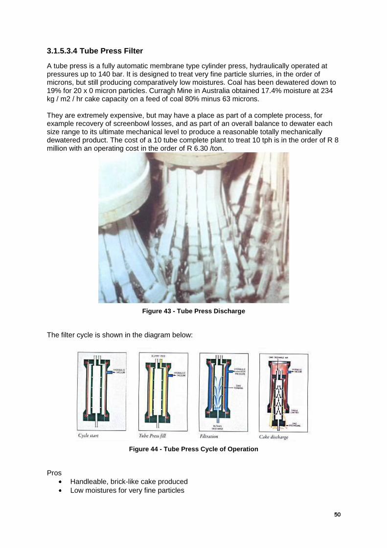
50
3.1.5.3.4 Tube Press Filter
A tube press is a fully automatic membrane type cylinder press, hydraulically operated at pressures up to 140 bar. It is designed to treat very fine particle slurries, in the order of microns, but still producing comparatively low moistures. Coal has been dewatered down to 19% for 20 x 0 micron particles. Curragh Mine in Australia obtained 17.4% moisture at 234 kg / m2 / hr cake capacity on a feed of coal 80% minus 63 microns. They are extremely expensive, but may have a place as part of a complete process, for example recovery of screenbowl losses, and as part of an overall balance to dewater each size range to its ultimate mechanical level to produce a reasonable totally mechanically dewatered product. The cost of a 10 tube complete plant to treat 10 tph is in the order of R 8 million with an operating cost in the order of R 6.30 /ton.
Figure 43 - Tube Press Discharge
The filter cycle is shown in the diagram below:
Figure 44 - Tube Press Cycle of Operation
Pros
Handleable, brick-like cake produced
Low moistures for very fine particles

51
Cons
Low unit throughput
Cost of multiple units
Solids capacity is a function of feed solids content
3.2 Thermal Drying
Thermal dryers have a major problem in terms of complexity, capital cost, operating cost and safety. In some cases, thermal drying is needed due to the climate, for example, in USA & Canada, coal is at risk of freezing if the external moisture is high. Thermal drying costs in the US can account for 25 to 30% of the cost of a coal preparation plant.
There are a number of principles that are common to all types of thermal dryer:
Drying rate increases as the gas (or other heating medium) velocity increases.
High temperature differentials increase drying rates, but also increase the chances of devolatalisation of coal.
Fine wet cake must be broken up in order to allow proper heat transfer.
Dryers are sized not in terms of solids throughput but in the amount of evaporation required.
Heat can be generated in a number of ways, although it would obviously be preferable to use waste heat, if available or to burn a cheap source of fuel such as discard coal from the plant. Gas can and should be recirculated to maximise the heat use as well as to form an inert atmosphere in order to avoid spontaneous combustion. Electrostatic precipitators or bag filters are normally used to clean off gases. Thermal efficiency can be lost by conduction of heat through the dryer equipment, heat leakage and due to the temperature difference between the drying gas and the dried coal. The two types of dryers are direct and indirect.
3.2.1 Direct
Direct dryers are designed such that the drying gas makes direct contact with the wet material. The hot gas is generated outside the machine and then blown directly into the dryer.
3.2.1.1 Rotary Driers
Among thermal dryers, rotary are probably the most common. Wet coal and hot drying gases are fed into a rotating cylinder, inclined at 2 - 50. Internal flights move the coal through the drum. Typical gas velocities are 0.5 – 3 m/s. Rotary dryers will use typically 3500 kJ/kg water evaporated. Exit gas temperature is usually 1050 0 C. They are typically slow to respond to changes, but the advantage is that the gas velocity is not needed to move the material. Large temperature and moisture gradients exist in the dryer, but only the outlet temperature can be used for control.

52
Figure 45 - Ohio Valley Coal Thermal Dryer
Pros
Moistures can be produced down to 0% moisture
Exhaust gases can be recycles to maintain an inert atmosphere
Generally robust Cons
Capital cost
Operating cost
Environmental problem from dust & SO2
Problems can be encountered with wet feed
Potential for explosions
Source Size Mass of Unit Tons treated Max Feed H2O
Expected H2O
IMS
Process
21m long x
5.2m diam.
175 tons 70 tph, 15 tph evap.
40% Down to 6%
Source Size Capex Installed Cost
Power Draw Operating Cost
Anon R 13.0 /ton coal
IMS
Process
21m x
5.2m
R 13.3 m R 18 m 776 kW R 9.0 /ton coal

53
3.2.1.2 Fluidised Bed
The fluidised bed arrangement below is actually a fluidised bed boiler designed and built by the CSIR. The However, a similar apparatus would be used as a fluidised bed dryer except that the hot air would be supplied by a coal combustor or by a diesel or kerosene fired burner. The dryer consists of a plenum chamber, a distributor plate and a drying chamber. The drying gas velocity in a fluidised bed dryer, typically 0.75 70 3.5 m/s, is not sufficient to entrain all the coal, so that a fluidised bed of coal is retained in the drying chamber. The finer fractions are collected downstream and recycled. The fluidised bed is reasonably easy to control as feed changes are damped by the mixing in the coal bed. Exit temperatures are in the order of 100 to 1500C.
Figure 46 - NFBC Fluidised Bed Boiler
Fluidised bed dryers will use typically 3500 kJ/kg water evaporated. Pros
Can dry down to any moisture
Relatively easy to control, tolerates feed fluctuations
Pollution can be controlled Cons
High capital cost
High operating cost
Pollution controls may be expensive
Feed would normally have a pre-dewatering step
Source Size Mass of Unit Tons treated Max Feed H2O
Expected H2O
CSIR 30 tph 40% Down to 0%
Enertek 60 tph 25% 7%
Enertek 58 tph 15% 4%

54
Source Size Capex Installed Cost
Power Draw Operating Cost
CSIR 30 tph R 9.5 m R 6.0 /ton coal
Enertek 60 tph R 8.2 m 500 kW R 10.48 /ton coal
Enertek 58 tph R 5.25 m R 8.1 m 250 kW R 6.5 /ton coal
3.2.1.3 Flash Dryer
Figure 47 - Flash Dryer Cutaway
Flash dryers have been operated for many years worldwide. Their principle of operation is very simple, but they can be difficult to operate under changing plant conditions. There is also the ever present safety concern with thermally drying coal. They generally operate by feeding wet material (normally the result of a first stage mechanical drier) from a hopper and introducing it to a hot air stream driven by a fan. This stream then meets hot air being blown from the opposite end, which changes the coal's direction and simultaneously dries the particles. Coal and hot air are then carried to an expansion chamber where they are separated. Coal is discharged via a cyclone and rotary valve and the hot gas is discharged to the atmosphere via dust collectors. Due to the speed of drying, approximately 60 seconds, the coal remains relatively low in temperature, even though the gas temperature may be in the order of 700 degrees C. the exit temperature is approximately 85 degrees C. There are two, 25 ton units plus six smaller units at Highveld steel. There are also units at Ergo plant but none on coal in South Africa. A reported heat efficiency of 60 to 65% is recorded which may be better with insulation. A 50 tons per hour unit working on 25% moisture coal and producing 10% moisture would require a 3 m diameter unit and a power consumption of 250 kW. Energy required is 33 GJ/hour, equivalent to 2 tons discard per hour. The flash dryer is sensitive to control and can be a problem if feed fluctuations are encountered. Flash dryers will use typically 3500 kJ/kg water evaporated.

55
Pros
Can dry down to any moisture Cons
High capital cost
Control is critical (and difficult) to minimise devolatalisation and explosibility
Environmental problem from dust & SO2
Feed would normally have a pre-dewatering step to 20% moisture
High costs associated with thermal energy required
Subject to high erosion rates due to high velocities of gas and particulates.
Source Size Mass of Unit Tons treated Max Feed H2O
Expected H2O
3m diameter
80 ft long
50 tph 20 Down to zero
Source Size Capex Installed Cost
Power Draw Operating Cost
R 7.5 millions
250 kW R 9.50 /ton coal
3.2.1.4 Pneumodrier
Figure 48 - Pneumodrier
The pneumodrier has been derived by Bateman Materials Handling (BMH) from pneumatic conveying. It simultaneously transports and dries particulate materials by introducing wet solids into a pneumatic conveying system driven by heated air. Material must be delivered to the unit in a handleable form. Temperatures and flow are monitored to ensure control and that drying is complete by the time it leaves the pneumodrier. The machine is relatively simple with few components and power can be reduced as the piping can be lagged to reduce heat losses. The system is relatively compact as the piping can be wound to reduce footprint. High wear areas such as bends can be made of ceramics if required.

56
Figure 49 - Pneumodrier Circuit
The control of the unit is critical as it is important to either keep the coal moving or recycle spent air to prevent combustibility. In addition, as the air evaporates the majority of the moisture, the amount of heat used can be reduced. Units conveying up to 60 tph have been made on particles up to 40 mm in diameter. Pros
Moving air does majority of water removal
Devolatalisation of coal is minimised
Lower energy requirement than normal thermal drying
Simultaneous transport
Simple maintenance requirement – ceramic bends, seals Cons
Ensuring relative velocities with ultrafine coal
Only used on coal at small scale
Source Size Mass of Unit Tons treated Max Feed H2O
Expected H2O
BMH 20 tph 40 % Down to 0%
BMH 3 off 20 tph units
50tph 40% Down to 0%
Source Size Capex Installed Cost
Power Draw Operating Cost
BMH 20 tph R 2 million R 2.36 m 400 kw /hr R 3.0
BMH 50 tph R 6 million R 7.08 m 1000 kw/hr R 3.0
Flash and fluidised bed dryers are generally more efficient than rotary drum dryers and it is believed that the pneumodrier is the most thermally efficient.

57
3.2.2 Indirect
3.2.2.1 Holoflite
This unit has been investigated a number of times in South Africa over the years and has invariably been rejected due to capital and operating costs as well as on safety grounds. There are also reports from Australia that problems may occur in material transport, the coal spins as the flights turn.
Figure 50 - Holofilte Screw Cutaway
The Holoflite consists of rotating hollow discs mounted on a hollow shaft through which a heated transfer medium, usually oil, flows at a temperature of 4500C. The coal transported by the flights is thus indirectly heated. The two best known units are the Holoflite from Svedala and the Thermal Disc Coal Drying system made by the Bethlehem Corporation. A few units are being used in North America and a few have been used in Poland.

58
Figure 51 - Svedala Holflite Dryer
Pros
Simple operation
Multiple energy sources may be used to heat the oil Cons
High capital and operating costs
Inert gas needed to reduce spontaneous combustion
Wet material is often difficult to transport by the flights
Source Size Mass of Unit Tons treated Max Feed H2O
Expected H2O
35 tph 35tph 22% 12%
Source Size Capex Installed Cost
Power Draw Operating Cost
Anon R 8.50 /ton
Coalwise 35 tph R 5.8 m R 8.1 m R 6.94 /ton
3.2.2.2 Torus Disc
The Torus disc or Torbed was developed in the UK by Torftech Ltd in Reading. It incorporates the features of a fluidized bed with cyclone and hovercraft technologies in one unit. Heat and mass transfer rates are increased to above that of entrained beds by suspending the material above linear jets using the support medium for suspension. The velocity of the support medium can be high (in excess of 50 m/s) and shaped to give a

59
horizontal component to the narrow bed (10 to 20mm deep) to form an annular shape. The result is a gently rotating bed of material contained within a compact shape (normally refractory brick lined). The high velocities provide extremely high heat and mass transfer. Almost any temperature of gas can be used in the process.
Figure 52 - Torbed Dryer
Pros
Reported high efficiency
Not used outside the UK Cons
No costs available, but probably expensive
3.3 Other types
3.3.1 Centridry
This machine is a solidbowl (or centripress) inside a thermal jacket through which a hot gas can be passed to reduce the final moisture to almost any level desired. As ever, this moisture should not be too low due to the moisture pick up and explosion risk. In addition, the hot gas must be controlled to provide an inert atmosphere.
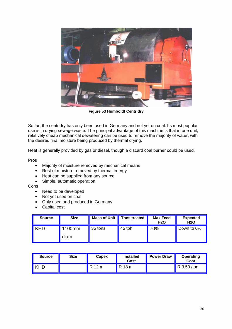
60
Figure 53 Humboldt Centridry
So far, the centridry has only been used in Germany and not yet on coal. Its most popular use is in drying sewage waste. The principal advantage of this machine is that in one unit, relatively cheap mechanical dewatering can be used to remove the majority of water, with the desired final moisture being produced by thermal drying. Heat is generally provided by gas or diesel, though a discard coal burner could be used. Pros
Majority of moisture removed by mechanical means
Rest of moisture removed by thermal energy
Heat can be supplied from any source
Simple, automatic operation Cons
Need to be developed
Not yet used on coal
Only used and produced in Germany
Capital cost
Source Size Mass of Unit Tons treated Max Feed H2O
Expected H2O
KHD 1100mm
diam
35 tons 45 tph 70% Down to 0%
Source Size Capex Installed Cost
Power Draw Operating Cost
KHD R 12 m R 18 m R 3.50 /ton

61
3.3.2 EA Process
The radio frequency (RF) assisted dewatering of slurries originally started as a process for assisting with the sintering of ceramics. It aims to assist conventional dewatering and drying techniques, for example with a horizontal belt filter in the diagram below. The incorporation of an RF throughfield electrode array into a horizontal flat bed vacuum filter permits volumetric heating. This results in higher cake temperatures, which allows the vacuum to pull out more liquid filtrate. Therefore, mechanical dewatering is enhanced by simultaneous application of vacuum and volumetric heating. It helps the evaporative process by raises cake temperature, reducing filtrate viscosity and reducing surface tension. This increases the flow of water from a cake with reports of up to twice the drying rate being possible.
Figure 54 - EA RF Assisted Dewatering
Pros
Assists conventional dewatering
Potential reduction of moisture and energy compared to the process to which it is added.
Cons
Untried on coal.
Costs specific to each application.
3.3.3 Microwave
Microwave drying is based on the property of coal that it is a poor absorber of penetrating microwave energy while water is a good absorber. Various laboratories have used microwave energy for sample drying and various investigations are carrying on, particularly in the US. No commercial applications have been reported so far.

62
3.3.4 Chemicals
3.3.4.1 Super Absorbent Polymers
Gel extraction is evaluated as a novel technique for dewatering fine coal slurries. This technique uses temperature-responsive gels to absorb water from slurries at low temperatures; after separation of the swollen gel from the dewatered slurry, the gel is heated slightly above ambient temperature, which causes it to release the water it absorbed. The gel can then be recycled. The equilibrium and kinetic properties of poly(N-isopropylacrylamide) gel were evaluated for utility in this process. The gels effectively dewatered slurries to around 70 wt% solids; performance was not a strong function of particle size, though coarser slurries (minus 16 mesh) could be dewatered to greater extents than the finer slurries (325 x 400 mesh). The gels showed no sign of deterioration over a period of two months and twenty cycles. This forms part of a related Coaltech 2020 report.
3.3.4.2 Dewatering Chemicals
Dewatering chemicals are becoming more common on South African coal plants.
They are normally used on the small coal fraction before basket centrifugation and
have been reported to reduce moisture of this fraction by 1% absolute. Middelburg
Mine Services reports 0.5% moisture reduction over the last six years.
Chemicals have not been used in screenbowl dewatering. However, the original flotation at Rietspruit used an oily based collector, Shellsol 2. Early work showed minimal solids losses in the centrate, 2 – 5%, even dewatering down to zero. More recently, work at Rietspruit has shown losses anywhere up to 30% of the feed in the centrate, but the collector has been changed. Logic, as well as some of the research work being done, indicates that the use of oil as a collector, while simultaneously aiding dewatering should be investigated properly. During the coal-oil flotation testwork, the effect was so strong that after using oil, coal put into paddocks could free drain down to 15% moisture in 3 days and was shown to reduce the “terminal” product moisture, with and without oil, after screenbowl centrifuge dewatering by 2% absolute. There is a theory, supported in another section (Australian and North American research), that micro agglomerates form such that there are no “zero mm” particles to dewater. Various tests have been done in South Africa, e.g. Goedehoop Colliery, showing how various percentages of slurry mixed with spiral product behave in a screenbowl centrifuge, but little work has been done on the preparation of screenbowl feed using oil, chemicals or thickening. There is a deficiency in targeted testwork to show how chemicals, collectors etc should be part of the whole system of fine and ultrafine coal recovery and dewatering. There may not be logic in using a collector which gives a 10% increase of yield and then loses 30% of the product through the basket of the centrifuge or increases filter cake moisture. Pros

63
Potential to increase solids recovery and reduce product moisture
Cheap compared to physical processes. Cons
Another cost, which may or may not be easily justified.
Good control is needed to maximise effectiveness and reduce costs
Need a systematic approach to testwork to define the optimal addition points and dosages for each operation.
3.3.4.3 Oil Agglomeration
Oil agglomeration is the one step process of recovering coal particles, forming agglomerates and screening out the non-agglomerated particles as waste. Extensive testwork was done from 1988 to 1992 by Randcoal which showed the process produced high quality coal, Van Dyks Drif LAC plant thickener underflow produced a minimum of 29 CV coal, but the agglomerates were too weak even at very high oil doses (up to 10% w/w) to be dewatered mechanically. From this work the Coal-Oil Flotation process was developed using Shellsol 2 and a high shear mixer. Pros
Potential to produce high quality coal
Agglomerates can be separated from non-agglomerated discards simply and cheaply.
Potential of using waste oils and lubricants from mines. Cons
Testwork showed little success on the coals tested in South Africa.
3.3.5 Other Aspects
Many aspects cannot be “pigeon holed” in a simple category:
Energy Sources Each of the thermal drying processes has an energy requirement in common. The energy used is critical in terms of capital and operating costs, safety and operability. Electricity is simple but is generally expensive, oil is expensive and a logistical problem and gas in South Africa is less of an option than in Europe. There follows no solutions, but a series of pertinent questions:
o Combustion of Discards It is usually mooted that energy supply is simple, as “…..we just have to burn the discards…..”. A series of questions arise from this statement
Do we have the people on the coal plants to do this?
Do we want to do this on a coal plant?
What are the real costs?
What are the environmental implications (now and future)?
How and where do we dispose of the ash? o Waste Heat
What is the viability in using waste heat from industrial processes? South African coal mines are normally sited away from urban areas, but they are often in reach of power stations, oil from coal plants, steel and ferrochrome operations etc. Is it possible to use the off gases and waste heat from these sources for mutual benefit?
Air swept cyclones

64
Escom often has a problem in handling ultrafine coal in its handling section feeding the stations. Once in the station it is cycloned and milled to the correct size for pulverised fuel. Could the air swept mills be adopted for use in drying coal, with or without heat?
Coarse Coal Dewatering Previous and later sections discuss this element in more detail. The important factor is the understanding of the balance in the plant to produce the correct product as most tonnage from plants is produced as a non sized product.
3.3.6 Summary of Costs
Based on the descriptions and costs given in this section the following summary can be given for the broad category of machines described:
3.3.6.1 Mechanical Dewatering Cost Summary
Type Tons per Hour
Capex Installed Cost
Operating Cost / ton
Expected Moisture
Dewatering
screen
55 R 123000 R 145000 R 0.11 30 – 35%
Screenbowl
centrifuge
50 R 1.8 m R 2.7 m R 1.60 12% fines 17% f + u
Solidbowl
centrifuge
50 R 1.6 m R 2.6 m R 2.20 30%
Scroll cent. 50 R 0.65 m R 0.8 m R 0.25 13%
Vacuum
drum
36 R 3.5 m R 5.6 m R 1.50 35%
Vacuum
disc
30 R 1.5 m R 2.40 35%
Belt press 40 R 2.5 m R 3.9 m R 5.0 35%
Ceramec 50 R 34 m R 45 m R 0.80 18%
HBF 50 R 9 m R 2.0 30%
Hyperbaric 50 R 12 m R 3.50 16%
Filter press
airblow7bar
50 R 12 m R 2.40 23%
Filter press
no airblow
50 R 14 m R 2.00 28%

65
Tube press 10 R 8 m R 6.30 17% u/fines
Larox 30 R 6.5 m R 9.8 m R 4.50 16%
3.3.6.2 Thermal Drying Cost Summary
Type Tons per Hour
Capex Installed Cost
Operating Cost
Expected Moisture
Rotary
drum
70 R 13.3 m R 18 m R 10.00 6%
Fluidised
bed
60 R 8.2 m R 8.00 5%
Flash
dryer
50 R 7.5 m R 9.50 5%
Pneumo
dryer
50 R 7.0 m R 3.00 6%
Holoflite 35 R 5.8 m R 8.1 m R 7.50 12%
Centridry 35 R 12 m R 18 m R 3.50 6%

66
4 South African Practice
Figure 55 - RSA Coalfield
Some of the instances that will be described for ultrafines are not necessarily
dewatering of product, but have been included as important examples of various
dewatering technologies that are in use in South Africa.
4.1 Fine Coal Treatment
Generally, fine coal in South Africa, particularly in the Witbank area is treated in spirals. The dewatering equipment used is either high frequency dewatering screens, scroll type centrifuges, screenbowl centrifuges and occasional uses of CMI type centrifuges. The moistures achieved are very dependent on the bottom size treated, but tend to be approx. 30% for dewatering screens down to 12% from screenbowl centrifuges.

67
4.2 Ultrafine Treatment
4.2.1 Ingwe
4.2.1.1 Middelburg South
In 1994, an 1100 tph destoning plant was installed at the then Duvha Opencast Colliery. The only ultrafines expected was due to adhering fines and breakage. As this was previously exclusively an Escom mine, a slimes dam was not available and it was preferred that none was installed, due to environmental reasons. As no fall back was available, 2 Shriver presses were installed with 1500mm x 150mm plates with 29 chambers each to treat a total of 29 tph. Cake thickness produced is 50mm and use of airblow ensures cake moisture consistently between 19 & 23%. This cake is sold to the Duvha Power Station and payback was therefore extremely fast.
Figure 56 - Middelburg South Plant Flowsheet
The automatic discharge has worked consistently well, manual intervention only occurs at maintenance time, and when the PLC detects a holed cloth. A theory for this excellent operation is that only 29 chambers were installed as the actual amount of slimes was unknown and the press is capable of taking 50 plates each. The shaft is therefore under loaded and has no problems. It therefore implies that an economic benefit analysis should be undertaken for under loaded automatic discharge vs. fully loaded manually operated machines. Operating costs are estimated at R 2.00 per ton treated.

68
Figure 57 - Shriver Filter Press at Middelburg South Plant
4.2.1.2 Rietspruit Colliery
Rietspruit was the first mine in the Witbank area to use flotation to recover ultrafines
for export. It uses Multotec’s Turbo columns to treat the minus 150 micron fraction.
Dewatering takes place together with spiral product in screenbowl centrifuges that
already existed, which were upgraded to increase capacity. Originally, one column
treated only 30 tph to prove the concept, but subsequently 2 more columns were
installed so that the entire 100tph of ultrafines feed could be treated. Flotation yield is
approximately 55%, so the fines / ultrafines ratio to the screenbowls is in the order of
100 tph: 55 tph, fed to 4 screenbowls, with one on standby. Combined product
moisture is 19% and losses through the bowl are a bone of contention, with various
studies showing losses anywhere between 2% and 20%.
4.2.1.3 Koornfontein Colliery
Towards the end of 1996, it was realized that the slurry dam would be full in less than a year. Three options were available;
An extension of the existing slimes dam that would only last for 27 months and cost R 17 million.
Pump underground, a distance of some 4.5km on surface and 8km underground and cost R 19 million capital and R 5.7 millions per annum.
Install filter presses and dispose of slimes as a solid or preferably sell to an Eskom power station. Capital cost estimated to be R 10.9 million (15 bar machine, no airblow) and with annual operating costs of R 1.1 million
Obviously, filter presses were installed, but due to budget cuts the machines were installed for R 10 million. This caused a major problem and the filter presses have subsequently been retrofitted with compressors to supply an airblow. The Shriver presses installed also seem to

69
be overloaded, which has caused numerous problems, which are continuing. A major problem is that of too many plates on the “shake-o-matic” which causes structural damage due to the violent shaking and does not allow the cakes too fall, as the plates do not move far enough apart. The filter costs are very high at R 7.30 per ton treated, mostly due to low cloth life and port wear on the plates, but the product is being sold at a profit. In 1998, a Multotec turbo flotation column was installed using a screenbowl centrifuge for dewatering, the cost of screenbowl operation is R 1.71 per feed ton. Presently, more flotation units (Outokumpu) are being installed also using a screenbowl for dewatering. Koornfontein ultra ultra fines, i.e. less than 20 micron coal are of excellent quality (29 CV) and losses through the basket, estimated at 10%, reduce the product quality.
4.2.2 Anglo Coal
4.2.2.1 New Vaal Colliery
New Vaal installed 2, horizontal belt filters instead of installing a slimes dam, as well as producing a product for Eskom from the fines degradation in the destoning plant as per Middelburg South Plant. The water circuit is closed apart from a bleed off that occurs when the ultrafines builds up. Each filter was upgraded from 27m2 to 54 m2 in 1990.
4.2.2.2 Kleinkopje
Kleinkopje is an Anglo Coal plant, which uses a Multotec turbo column cell to treat a portion of its ultrafines. Originally, dewatering of flotation product mixed with spiral product took place using H900 scroll centrifuges. However, this mine is doing considerable work (much of it not for public consumption) that will be used throughout Anglo Coal. Some of the techniques that have been tried are the AECI Carbolite process as well as some pelletising work.
4.2.3 Sasol
4.2.3.1 SSF Plants
Sasol’s plants which supply sized coal (+6mm) to the gasifiers also sends the minus 6mm coal to the two on site power stations. There are two sizing plants, East and West, each with a similar configuration of ultrafine dewatering equipment. Moisture is important, but not commercially, a problem as the “customer” is internal. There is a wide mix of drum and disc filters as well a horizontal belt filter.
4.2.3.2 Twistdraai
Twistdraai is the Sasol export plant and it uses five Delkor filter presses to dewater raw ultrafines, which is then sent to the Sasol Synthetic Fuels plant on the same site.

70
4.2.4 Duiker
4.2.4.1 Atcom
When Atcom was first built, in 1992, an HBF was installed to dewater spiral product.
In 1996, Atcom installed a flotation circuit using Jameson cells and screenbowl
centrifuges for drying as the original HBF did not have sufficient capacity for the
extra water and it was felt that the HBF moistures were too high.
4.2.4.2 Arthur Taylor
In 1987, Arthur Taylor Colliery installed an HBF to close the water circuit by dewatering the thickener underflow. This was generally successful except when high clay contents were delivered with the feed and caused overflow of water. At a later point however, spirals were installed in the plant, the product of which was diverted to the HBF, while the thickener underflow was pumped to space created underground.
4.2.4.3 Tselentis
Tselentis Colliery installed the first filter press in South Africa on coal, which is now no longer used. It was originally installed to replace the use of a slimes dam, but a pipeline has been installed to send slurry underground. The Filter press used was a Shriver press (automatic discharge), 800mm x 800mm plates with 41 chambers treating 6 tph producing 30% moisture at 4 cycles per hour.

71
5 International Practice
A survey in 1996 produced the following breakdown of coal preparation methods :
China Russia USA Australia
Jigging 60% 48.8% 46.3% 16%
DMS 23% 23.6% 32% 57%
Flotation 14% 9.9% 4.4% 15%
Other methods 3% 17.7% 17.3% 12%
Dewatering is a complex subject and very site specific as the actual quality, particle size distribution and cost of local manufacture all contribute to the decision of how coal should be dewatered. Probably, the greatest influence is that of each company’s marketing Department and the market in which the coal is to be sold (the sale of thermal or coking coal being the principal difference). Personal preferences as well as a country’s trend also plays a role. One email summed up the situation by saying “…….Australia do not use screenbowl centrifuges, just horizontal belt filters (HBFs), whereas the US will not use HBFs, just centrifuges……..” In this light, each country’s experiences should be used as a guide to what is available and could be used in the South African experience.
5.1 Australia
Australia is similar to South Africa in terms of coal type (both being Gondwanaland coals) and both countries export the same order of steam coal tonnage, although Australia does export almost the same quantity of coking coal. The coal type dictates that attention must be paid to coal quality in terms of calorific value and moisture, as well as needing yield to be maximized. One plant, Ravensworth, which is not currently being operated, achieved the dubious honour of producing a washed product of lower specific energy than its feed, due to the increased moisture! Upgrades of fine and ultrafine plant in Australia have taken the form of either enlargement of existing capacity, installation of fine coal thickeners ahead of filtration as at Goonyella or adding new filters. During the 1990’s the main vacuum filtration unit has been HBFs of which 15 were installed in 9 plants (approximately 3000 m2). The unit that has seen wide use in spiral coal dewatering is the HP36 or FC 1200 fine coal centrifuges. ACARP report 3042 states that “…………………….as of 1999, disc and drum vacuum filters are still the most popularly used fine coal dewatering equipment, particularly in Queensland. The only devices observed for dewatering tailings were belt press filters and solid bowl centrifuges. Screenbowl centrifuges (SBC) rank second, and are the most commonly used machine in NSW. Use of CMI fine coal centrifuges is increasing due to their lower cost, smaller space requirement and reasonable performance. Moistures are usually 21-25 percent for filter cakes and 14-17 percent for centrifuge products. Screen bowl centrifuges are less efficient at capturing fine solids, but this can lead to a significant ash reduction in product. For tailings dewatering, belt press filters are superior to solidbowl centrifuges in cake moisture and handleability, and flocculent consumption. Pressure filtration is an effective technique to improve dewatering of fine coal, particularly for minus 0.1 mm material. Of the hyperbaric filters, the KHD Humboldt Wedag, Hyperbar and Andritz HBF are most promising. They are capable of reducing product moisture by 4-5 percent while increasing capacity by 100 to 200 percent in comparison with conventional

72
vacuum filtration. Their disadvantages are higher capital cost, a more complicated structure, and possibly higher operating costs. Other pressure filters, such as Larox PF, Python pinch press, also can be used in dewatering superfine (minus 0.1 mm) fine coal. Apart from CMI HP-36B, there is another fine coal centrifuge (Siebtechnik or Wemco H-900) on the market. Both the machines are high G (500 G's) centrifuges, and have similar dewatering performance. Product moisture is around 12 percent with approximately 50 tph capacity in dewatering minus 0.5mm fine coal. The phoenix belt filter press has the features of an improved pressure/ shear zone and low maintenance design. This machine may be a good choice for tailings dewatering. No major developments in flocculants and coagulants have been identified. However, Quaker Chemical provides two chemical aids for coarse and fine coal dewatering respectively. Nalco's "Opticus™" and Allied Colloids' "Clarometer" flocculant dosing control systems can be applied to thickeners and filters………………………………”
5.1.1 Burton Colliery & Moranbah North
The diagrams and photos show a typical James Donnelly plant in Queensland, Burton Colliery, with a Jameson cell feeding its product directly onto an HBF.
Figure 58 - Burton Colliery Flotation & HBF
The Moranbah North Flowsheet shows a similar layout, which has become a de facto standard in Australian plants.

73
Figure 59 - Moranbah North Flowsheet
5.1.2 Peak Downs
Peak Downs is a mine on the Bowen Basin of Queensland that produces 6.3 million tons of coking coal per annum. Sixteen Microcel flotation columns were installed in 1995 to replace the conventional flotation machines. It was felt that the improved quality would justify the change. The existing disc filters were kept, producing a moisture of 22 – 24%. An interesting observation is that by producing a better quality the coarser coal circuits can be underwashed to attain the same overall quality and this produces an overall lower moisture.
5.1.3 Saraji
A major new coal flotation plant was built at Saraji, Queensland operated by BHP in 1999. Eight Microcell columns were installed to treat 400 tph of –0.5mm feed, replacing conventional cells. The AU$ 18 is expected to be paid back in 12 months. As at Peak Downs, a major advantage in using flotation to produce a high quality product is that more coarse coal can be produced because of underwashing, which can increase total plant yield and reduce overall moisture. It is reported that the deep froth used with washing can remove high ash slimes, which aids dewatering. The product can then be dewatered in screenbowls or filters.
5.1.4 Tailings Recovery
It is estimated that around 5 million tons of coal are dumped into tailings ponds each year, even allowing for the increase amount of flotation. The only group recovering tailings ponds presently in Australia is Minpro. Economics are difficult, unless done on a sufficient scale and with relatively consistent feeds. Recovered coal has, up to now, been added back to the normal product stream after centrifuging. This must be relooked at now as the feed streams are getting finer as the easy coarse material runs out.

74
The general view is that other methods such as high speed centrifuging, agglomeration and even thermal drying will need to be used in future. Of these agglomeration is a favoured option as a sized product can be made, as long as the price is right.
5.2 North America
Both the USA and Canada have practiced flotation of coal using a variety of techniques to dewater the products. Slimes dams have been used in some cases to dispose of slimes without treatment. Where possible, flotation tails have been dewatered in order for them to be disposed of as solids with coarser discards. Often a belt filter press has been used in this application. Depending on location and customer, thermal drying has been practiced, but this has generally been deemed undesirable for economic and safety reasons and latterly for environmental reasons. Sometimes however, thermal drying must be used to avoid freezing of the product. North America has benefited from competition in that equipment is, in comparative terms, cheaper than South Africa as the market size induces competitive pricing of mechanical equipment. Because of this screenbowl centrifuges, supplied by Decanter, Broadbent, Envirotech et al are prevalent, supplying reasonable moisture at a reasonable price. There are 2 HBF installations in the USA, one being in the Buffalo Coal Co. plant in West Virginia. However, it is more than 10 years since an HBF was last installed in North America. The recovery of discarded slimes is being investigated actively presently as the huge slurry ponds pose a serious environmental liability. The US government have encouraged a number of large projects for the recovery and utilization of fine coals.
5.2.1 United Coal Company
United coal and its research branch UCCR (United Coal Company Research corp.) have been investigating the use of column flotation cells, the first being installed at Tanoma Mining in 1985. Later, UCCR developed the Flotaire flotation unit. Simultaneously, they realized that an economical, non polluting method to dewater the flotation product was needed to replace thermal drying. To this end a high rpm batch centrifuge was developed. This steps up the speed from an initial 15 seconds at 1200 rpm to 3800 rpm for 30 to 40 seconds, reduces speed to 1200rpm at which point a blade is inserted to “cut out” the coal. This project was carried out with Roberts & Schaefer Co.
5.2.2 An Eastern US Coal Plant
In 1998, Jameson cells were installed at an Eastern US coal plant, in particular to recover the ultrafine (-44 micron coal). The product is de-aerated, de-foamed and then dewatered in plate and frame presses to a moisture of 22%.
5.2.3 Lady Dunne
Extensive testing of HBF, Drum filters, screenbowl and solidbowl centrifuges took place, after it was first determined that thermal drying would be at least twice as expensive to dry and almost four times more expensive to thermally dry then briquette. Eventually the granuflow option was chosen whereby a screenbowl centrifuge was used to dewater the coal, after the feed had been mixed with 6 – 8% orimulsion.

75
5.3 UK
5.3.1 Gascoigne Wood
The latest flotation plant to be installed in the UK is at RJB Mining’s, Gascoigne Wood where column cells were installed in 1997. The flowsheet is shown below.
Figure 60 - Gascoigne Wood Flowsheet
The water circuit had to be completely closed to comply with environmental regulations. Before the installation of the flotation plant all slimes were dewatered in Eimco belt filter presses and a later addition was classifying cyclones to remove the high ash minus 60 micron material to produce a 20 to 30% ash product for sale. At that point, flotation was investigated for the minus 60 micron material. The flotation product is dewatered in the same belt filter presses to produce a 36 to 38% moisture coal to be fed to the power station. Tailings are also dewatered by belt filter presses prior to tip disposal. This was not the preferred choice of dewatering equipment, but it existed and overall capital was reduced. Large amounts of flocculent are required prior to the belt filter presses.
5.4 Germany
Due to a long period of environmental concern, Germany has a wide range of dewatering equipment, very little of which involves thermal drying. Dewatering of tailings in Ruhrkohle plants is by four methods (as at 1995); Filter presses 61% Impoundments 17% Solidbowl centrifuges 18% Belt Filter Presses 4%

76
The trend is towards filter presses, for dewatering of tailings, as they consistently produce a handleable cake. The filter presses used are large with consequent high capital requirements and other alternatives are being explored. Centripresses, which are modified solidbowl centrifuges, where the screw is made with variable pitch in order to compress the sludge have been tried. These can reduce solidbowl moistures by 5 to 10%. Centripresses are common in sewage sludge applications. Flotation concentrates have generally been dewatered using continuous pressure filtration, usually disc or drum filters with KHD hyperbaric filters being occasionally used.
5.4.1 Prosper Plant
One of the most interesting plants, in terms of dewatering, is that of Ruhrkohle’s Prosper. As the number of coal mines in Germany decreases, the expensive equipment (in which dewatering certainly fits!) is moved to the remaining operation mines. Consequently, Prosper, a 1400tph plant using coarse and small Batac jigs, has the following dewatering equipment:
Flotation dewatering
1 x 120m2 Humboldt vacuum Disc Filter 1 x 60 m2 Humboldt disc vacuum filter 1 x 120 m2 Humboldt hyperbar pressure filter 2 x 60 m2 Humboldt rotary drum vacuum filter 1 x 90m2 Kraus & Mather disc vacuum filter 2 x Humboldt screenbowl centrifuges, 1100mm x 3.3 metre long Tailings Dewatering
Figure 61 - Prosper R&B Tailings Filter Presses
7 x Ritterhaus & Blecher chamber filter presses, each 140 off 2 x 2 metre plates using a 90-minute cycle. Generally, moistures of 23 – 24% are achieved using vacuum filters and 19% using pressure filters. The hyperbar works at 2 bar with 4 bar airlock pressure and has a capacity of 60 – 80 tph. The rotary lock inflated rubber seal is considered to be an operational problem. The 120m2 disc filter has a capacity of 20 – 25 tph. The screenbowl centrifuges achieve 19 – 20% moisture on 300 g/litre feed concentration at 25 tph. The ash content of the screenbowl feed is 10% and the screenbowled product is 8%. The centrate contains in the order of 50 g/litre, which is returned as process water to flotation, as this is found to reduce foaming in the thickener. The filter presses are able to treat 16 tph per filter with product moisture of
20%.

77
5.5 Poland
A number of methods are being used to dewater flotation products. Disc and drum filters are very common and work is continually being carried out on the improvement of vacuum filtration performance. Polish plants producing steam coal generally only treat the + 20mm coal and only a few wash the fine coal as it is often relatively low in sulphur. At some mines the fine (1mm x 0mm) coal is dewatered using plate and frame presses for disposal in landfills, occasionally it is blended in with clean coal. The Jastrzebie collieries are primarily low volatile coals producing coking coal. These plants often use baum jigs on the 100mm x 0mm feed with froth flotation to reprocess the 0.5mm x 0mm fraction. The clean coal product is generally dewatered using vacuum disc filters and then thermally dried in rotary dryers. By 1998, new stringent environmental regulations (as part of the bid to join the EU) were promulgated. These made it more difficult to use the unwashed fine coal. This dictated the washing of the 20mm x 0mm coal fraction. The fine coal produced has had to be treated more efficiently either for final disposal or for product. This has seen the introduction of belt press and horizontal belt filters. A new mine, Staszic, uses dewatering screens for fine coal discards, belt presses for ultrafine refuse and Decanter screenbowls for fine coal products.
5.6 China
China is the largest producer and consumer of coal in the world. In 1994, coal provided 75% of the country’s primary energy, including 76% of energy for power generation and 80% of domestic energy. By end 1995 there were 226 coal preparation plants with a total annual throughput of 306 million tons (out of 1.1 billion tons total) of which 138 treated coking coal and 88 plants (131 million tons) producing thermal coals. The plants use jigging and flotation or DMS, jigging and flotation.
A report of 1996 suggested that various new technologies were being researched to
improve plant efficiencies. These include the use of more dense medium processes,
dry cleaning (particularly important in the dry west China) and the development of
equipment for flotation and dewatering of fine and ultrafine coal.
Currently, China’s coal preparation plants normally use vacuum filtration, either disc
or drum, which produce product moistures of about 30%. A study has begun on
using fully automated filter presses, each with a capacity of 35 to 40 tph and
producing a moisture content of 16 to 18%.
Incidentally, column flotation is the preferred flotation method chosen for study.
5.7 India
As at 1995, there are 22 wash plants in India, 15 operated by Coal India, 6 by steel plants and 1 privately owned. In 1993, these plants treated 15.5 million tons of coal. Originally, in

78
most cases only the coarse coal was washed, but now most plants baths, DM cyclones as well as froth flotation on the minus 0.5mm material. This change was brought about due to the deterioration of coal quality into the coal plants, as well as their customers preferring to operate at higher efficiency using higher quality feedstock. Drum and disc filters have been used to date, in addition, there is a large quantity of coal in ponds that are treatable, with potential use in steel plants.

79
6 Review of Research
6.1 South Africa
Research in South Africa is sporadic and has generally been undertaken by each mining house in isolation. Much of the work has been done on site on a practical basis with no fundamentals. Some of the work that has happened over a period of years include:
Oil agglomeration, including the effect of oil on screenbowl moistures and free drainage.
Pelletising
Various on-line centrifuge comparisons
Dewatering chemicals
6.2 International
6.2.1 Australia
Australia, by means of the ACARP (Australian Coal Advanced Research Programme) funding seems, on the basis of publications and internet searches, to be the leader in research into most matters pertaining to coal preparation. Obviously, one of their focuses has been on the dewatering and drying of fine and ultrafine coals. Some specific projects have been:
6.2.1.1 Coarse coal dewatering
ACARP Project 3003 Conclusions (edited for this report)
1. The moisture content of coarse coal after centrifugation has been found to vary significantly:
2. …. 3. Normal distributions or multiple normal distributions for multiple seam mines, appear
to provide a convenient method of describing the plant, fine coal and coarse coal moistures. This could be of use in determining real changes to plant operations and the application of statistical process control procedures.
4. Little dependence of coarse coal moisture was found with respect to time of plant operation. There was a small positive correlation with the feed rate to the plant. The product ash value for the two coals examined also had little impact.
5. Laboratory centrifuge technique has been developed, which for relatively coarse coal feeds, has identified that there are three types of water associated with a coal with respect to its potential for removal by centrifugation:
a. There is an amount of water removed easily with centrifugation. This excess water appears to have little relationship with the coal.
b. There is an amount of water, which is closely related to the coal surface, causing a slower rate of removal.
c. There is a Non-Centrifugable Moisture (NCM) which cannot be removed by centrifugation even using much longer times. It comprises a small amount of surface water, as well as an amount of internal water within the coal structure. Particular coals have different capacities for holding internal water.
6. It has been found that the results from the laboratory centrifuge are erroneous when the samples have been allowed to begin drying. This is considered to be due to

80
problems of rewetting the coal, particularly with respect to water being unable to penetrate the dried internal pore structure of the coal.
7. The Non-Centrifugable Moisture results from the laboratory centrifuge work can be interpreted as the coal having an internal moisture, NCM, (which is unaffected by particle size) and an external moisture, NCM s , which varies with particle size, and is proportional to the surface area. Values of NCM and NCM s are given for the coals tested.
8. Four boreholes were obtained form the coal seams involved in the plant investigations. There are significant differences between the NCM i values, with the Goonyella Middle seam having a substantially higher value (4.2%) than the Goonyella Lower (3.1%) and the Middle seam from the Isaacs Pit (3.4%). All the Goonyella cores are much higher than that for the Dysart seam at Norwich Park (2.3%). The surface moistures were similar for all the material from the boreholes.
9. The mercury porosimetry tests provide relative internal pore volumes for the different coals tested. All the Norwich Park samples have lower internal porosities than those from Goonyella. For both coals, the dull material has a higher pore volume than the bright, and also retains more mercury during extrusion. The dull coal from the Goonyella Middle seam contains significantly higher porosity than the Lower dull and all the bright samples. The dull material from the Isaacs pit had a porosity between the Middle and Lower seams.
10. Analysis of the results from the major samples obtained from the two plants, as well as samples obtained at five other mine sites has indicated that the moisture level of the coal after centrifugation and its propensity to vary, is controlled by:
a. the amount of moisture held internally within the coal; b. the specific surface area of the coal being presented to the centrifuge; c. the hydrophobicity of the coal as indicated by the rank (reflectance); d. the amount of ultra-fine (slimes) material associated with the coarse coal,
which appears to affect the drainage of water from the coal particle surface. 11. The overall range of the rank of the coals involved in this investigation, as measured
by reflectance, varied from 0.7 to 1.65. The model was able to explain 80% of the variation in the 25 samples investigated.
12. At all sites investigated, it was found that there was a significant amount of coal breakage in the centrifuge. Evidence suggests that the majority of the breakage occurred as the coal leaves the centrifuge, and any analysis based on the final product size distribution could be erroneous.
13. At Goonyella, washing the coal (ie the removal of the ultra-fine particles led to decreases in moisture level.
14. Scanning electron microscopy has identified that the surface of the coarse particles is covered by a layer of ultra-fine particles, with the majority of these being carbonaceous in nature.
15. A model incorporating the above factors has been developed. It provides an approach for estimating the moisture level which can be achieved by centrifugation of coarse coal.
6.2.1.2 Super absorbent polymers
JK Centre at the University of Queensland has been doing work on a process for reducing the moisture in filter cake by using super absorbent polymers. These are highly cross-linked polymers, which absorb several times their own weight in water and swell, while maintaining their own structure. The reagents could be screened off, regenerated by adjustment of pH and recycled. From pilot plant work costs are estimated at R 1.0 to R 2.00 per ton % of moisture removed, assuming 50% polymer loss per 15 cycles.

81
Figure 62 - Pilot Scale Superabsorbent Dewatering Process
Figure 63 - Residual Moisture of Fine Coal Using Superabsorbent Polymers
The graphs show the potential of this work. The principal dilemma is in the practice of how to allow large amounts of coal to contact with polymer for long periods of time.
6.2.1.3 Fundamentals of Fine Coal Dewatering
6.2.1.3.1 Abstract for Project C6049
This project builds on earlier work that concluded that controlling cake microstructure was a potential means of reducing equilibrium cake moisture. This result led to the hypothesis that by modifying cake microstructure during the drying phase of the filtration cycle, cake moisture could possibly be lowered. Secondly, the project established the potential of the Single Leaf Filter Test (SLFT) apparatus as a possible tool for sizing horizontal vacuum belt filters. The objectives of this project were:

82
To trial microstructure alteration methods for reducing cake moisture on horizontal vacuum belt filters, and to derive and test a scale-up procedure for sizing full-scale horizontal belt filters based on data obtained with the Single Leaf Filter Test (SLFT) apparatus.
Moisture reduction by mechanical cake mixing.
Initial attempts to alter cake microstructure using vibration and compaction, conducted on pilot-scale and full-scale horizontal belt filters, concluded that neither altered cake microstructure sufficiently to reduce cake moisture.
Continuous cake mixing trials were conducted under controlled laboratory
conditions, using a double-helix ribbon blade mixer to agitate filter cakes
formed in top-fed laboratory leaf filtration tests during the drying phase. Such
mixing reduced cake moisture by up to 4%. Faster dewatering kinetics were
also observed. It is estimated that belt length could be reduced by 20% to
30% while maintaining cake moistures.
Several factors were identified as having an impact on moisture reduction by cake mixing:
Moisture reduction was found to be very sensitive to the time at which mixing is initiated during the drying phase.
Moderate air purging was found to marginally improve moisture reduction.
Mechanical mixing was most effective with finer size fractions.
The mixing technique was very effective in coping with the extremely cohesive nature of moist fine coal particles
Projected values for discharge moisture and belt size were obtained from a comprehensive series of laboratory mixing tests with a fine coal flotation concentrate from Central Queensland. The values are summarised in the table below.
With Mechanical mixing time at which mixing starts (s) *Predicted belt area (m2) Cake discharge moisture (%) No - 100 25.8 Yes 30 67 25.8 Yes 40 80 23.2 * Fixed belt width assumed Vacuum belt filter sizing using the Single Leaf Filter Test apparatus
The project confirmed the possibility of using the SLFT apparatus to size horizontal vacuum belt filters. Firstly, site tests confirmed the agreement between SLFT and belt filter performance under the same operating conditions. A method for scaling up SLFT test results was derived. It permits calculation of the minimum effective belt filter area required to meet a number of user specified constraints, including feed rate and cake discharge moisture. The technique was compared to actual plant performance data and good agreement resulted. It also proved useful as a means of deriving information about the behaviour of operating belt filters. In spite of adverse experimental conditions that prevented conclusive comparison of HBF and SLFT form times, excellent agreement was obtained between their respective dewatering kinetics, confirming the potential of the SLFT as an HBF sizing tool.

83
A sizing scheme was developed from which belt length, width, linear speed, operating cake height and minimum vacuum pump capacity, necessary to treat a specified tonnage and yield a set product moisture, can be determined from SLFT measurements alone. The results were found to compare well with the average HBF performance at BHP Coal Riverside mine.
o Examination of filter cake formation o Mathematical modeling of filtration processes
6.2.1.4 Improved dewatering in Fine Coal Centrifuges
6.2.1.4.1 Abstract for Project 7039
This report summarises the results from a project aimed at adapting scroll centrifuges for application to the dewatering of flotation concentrates. The technical challenge was to enhance solids capture by incorporating a laser-cut screen into the design of the basket. The main impetus for the project was to reduce the high cost and footprint size of the technology currently used to dewater fine coal. It is thought that the proposed approach to the problem is novel. The project has shown that a pilot-scale scroll centrifuge can be used to dewater froth concentrate. A number of different basket designs were tested, the best results being achieved with a basket comprising a laser-cut screen of aperture 70 mm. The best result on a sample of untreated flotation concentrate, which was taken from the open trough flotation cells at the Russell Vale coal preparation plant in NSW was a solids recovery of 82 wt% at a product moisture of 24.3 wt%. By comparison, the best product achieved with a conventional wedge wire basket was a similar moisture content but solids recovery was only 64 wt%. This could only be achieved after the feed had been artificially thickened. Conditioning of the centrifuge feed with either polymer flocculants or an emulsion of waste oil led to an increase in recovery up to 98 wt%. Probably the most encouraging results were product moisture values of 23.1 to 25.2 wt% with recoveries of between 87 and 90 wt% with the oil, and recoveries up to 88 wt% with the polymer. It is thought that optimising additive selection and conditioning parameters, as well as screen aperture and open area, could improve performance still further. The results were obtained using centrifuging conditions (centrifugal force, feed solids, feed rate) in the pilot-scale machine, which it should be possible to translate into conventional designs of commercial scale machines, without downgrading of solids throughputs that are currently processed. However only with full-scale trials will it be possible to establish this assertion with certainty.
The state of the laser-cut screen basket was monitored over the course of the project. Whilst operating hours were few relative to commercial baskets, there were no significant changes in basket aperture, nor any other overt signs of wear except for a few minor scratches and one small indentation. Clearly, selection of a sufficiently wear-resistant material for fabricating the screens will be crucial if this concept is to find commercial application.
6.2.1.4.2 Shear coagulation of Fine Coal to Improve Moisture Control
Conclusions

84
Shear coagulation has been shown convincingly to be a real effect. Using shear in the form of energy supplied by an impeller, it is possible to achieve higher filtration rates and lower residual moisture levels than with a coagulant alone. Application of shear to a flotation product in the presence of coagulant leads to increases in filtration rate with increase in the shear rate (stirrer speed) and coagulation time, up to a point. Plant pilot-scale tests have shown that a net low energy input (0.44 kWh/t solids) is all that is required to observe the effect in practice. A Rushton type (Disc style - high shear) impeller provided the best results for a given power/energy input. The filtration rate of a flotation product from two operating coal preparation plants has been increased using shear coagulation. It is possible to coagulate fine coal and ultrafines, to produce dense, compact, high-strength aggregates rather than loose flocs. Conditioning time is found to be an important variable. When the particle size distribution is monitored as a function of time, it is found that the sub-10mm fraction can be minimised, and the mean particle size can be increased by a factor of three or more. The coagulant addition rates are relatively low. Success has been achieved at concentrations as low as 15g/tonne, dry solids basis. The filter cake formed from shear-coagulated coal appears to be quite strong. There is no evidence that the cake compresses as the filtration pressure increases. Large increases in filtration rate can be achieved without the need for hyperbaric filtration. The filter cake total moisture from operating preparation plants has been decreased using shear coagulation. Alternatively, increased filter cake throughput could be obtained without an increase in filter cake total moisture.
6.2.1.4.3 Abstract for Project 4052
This report summarises the results from a study aimed at improving the solids capture of scroll centrifuges. The main objective was to assess at pilot and commercial scales, the performance of a scroll centrifuge fitted with baskets of finer aperture (ie 250 or 125 µm) compared with the conventionally fitted size of 375µm. Improved solids capture might allow the scroll centrifuge to be applied to finer feeds. It was intended to monitor the wear of the commercial scale basket which was to be hardened with a coating of tungsten carbide. In addition it was intended to gain a greater understanding of the main parameters which affect the performance of scroll centrifuges. A literature review showed that there was virtually no prior published work on scroll centrifuges and that the proposed approach in this project had not been attempted before. After some preliminary bench scale tests and modelling, a series of trials were performed at a CMI pilot scale (ca 2 tph feed solids) scroll centrifuge at the Clarence CPP in NSW. Unfortunately, no meaningful runs were possible with the 375µm basket due to rapid blinding with near size particles. In tests with the other baskets, the greatest influence on solids capture was not the basket aperture but the solids density of the feed, suggesting that the kinetics of bed formation is the controlling variable, and that the particle bed itself is the main medium for capturing particles and not the basket. Product moisture was determined primarily by feed size and centrifuge spin speed, which is not surprising but the extent of moisture reduction that could be achieved for relatively modest increases in spin speed was unexpected. Since there seemed little difference in the performance of the 250 and 125µm baskets, it was decided to opt for the coarser aperture for the commercial scale trial. A 250µm tungsten carbide lined basket was trialled at Rix's Creek, CPP in the first half of 1998. Sampling runs were conducted in March and May. The first objective, to improve fine

85
coal dewatering, was not achieved. Moistures ranged from 20% to 43%. This may have been due in part to excessively fine feed, having 20-38% <100µm. The corresponding product contained 16% -30% <100µm. The second objective, to improve solids capture, was achieved when the basket was in good condition. Sampling in March showed solids recovery 92% - 94%. However in May solids recovery had fallen to 75% - 79.8%. Over this period the mean aperture had worn from 287µm to 731µm. The third objective, to extend basket life, was not achieved. On completion of the trial the basket had run for 611.5 hours, handling 16,896 tonnes of feed at an average rate of 27.6 tph. All the tungsten carbide coating had worn off, and the basket had failed in a number of places. Some anecdotal evidence is cited that much longer basket life has been achieved, but the plant in question could not locate operational records to confirm this belief. The report recommends further, as the results of the pilot testing are quite encouraging. An alternative wedge wire profile is suggested.
6.2.1.5 Advances in Coal Preparation Technology – Volume 3: Fine Coal and
tailings Dewatering Practice & performance
Summary In this report, the emphasis is on fine coal dewatering. Unless noted otherwise, comments generally relate to fine coal (not tailings) dewatering. (The only devices observed for dewatering tailings were belt press filters and solid bowl centrifuges). Disc and drum vacuum filters are still the most popularly used fine coal dewatering equipment, particularly in Queensland. Screen bowl centrifuges (SBC) rank second, and are the most commonly used machine in NSW. However, application of CMI fine coal centrifuges is increasing due to their lower cost, smaller space requirement and reasonable performance. Moistures are usually 21-25 percent for filter cakes and 14-17 percent for centrifuge products. Screen bowl centrifuges are less efficient at capturing fine solids, but this can lead to a significant ash reduction in product. For tailings dewatering, belt press filters are superior to solidbowl centrifuges in cake moisture and handleability, and flocculent consumption. Within the dewatering equipment surveyed, pressure filtration is an effective technique to improve dewatering of fine coal, particularly for minus 0.1 mm material. Of the hyperbaric filters, the KHD Humboldt Wedag Hyperbar and Andritz HBF are most promising. They are capable of reducing product moisture by 4-5 percent while increasing capacity by 100 to 200 percent in comparison with conventional vacuum filtration. Their disadvantages are higher capital cost, a more complicated structure, and possibly higher operating costs. Other pressure filters, such as Larox PF, Python pinch press, also can be used in dewatering superfine (minus 0.1 mm) fine coal. Apart from CMI HP-36B, there is another fine coal centrifuge (Siebtechnik or Wemco H-900) on the market. Both the machines are high G (500 G's) centrifuges, and have similar dewatering performance. Product moisture is around 12 percent with approximately 50 tph capacity in dewatering minus 0.5mm fine coal. The phoenix belt filter press has the features of an improved pressure/ shear zone and low maintenance design. This machine may be a good choice for tailings dewatering. No major developments in flocculents and coagulants have been identified. However, Quaker Chemical provides two chemical aids for coarse and fine coal dewatering

86
respectively. Nalco's "Opticus™" and Allied Colloids' Clarometer" flocculent dosing control systems can be applied to thickeners and filters. Alternative Equipment Pressure filtration is an effective technique for improving dewatering of fine coals since it overcomes the fundamental difficulty in vacuum filtration, producing more than one atmosphere (2-6 bar) of pressure drop across the filter cake. Of the hyperbaric filters, the KHD Humboldt Wedag and Andritz HBF are the most promising equipment at present. This type of machine is capable of reducing product moisture by 4-5 percent while increasing capacity by 100-200 percent in comparison with conventional vacuum filtration. Their disadvantages are higher capital costs, a more complicated structure, and possibly higher operating costs. The Ceramic PC capillary action positive pressure filter recently developed by Outokumpu uses ceramic plates as a filter medium within a high pressure vessel. This type of equipment may have the potential to further reduce the cake moisture if compared with the KHD and Andritz types, however, its capacity may be a matter for concern. Tests have not yet been conducted for fine coal. Te Larox PF pressure filter is a vertically constructed press with airblow drying under pressure. It achieves very low cake moisture, and requires little floor space. The Python pinch press, which is considered as the successor of the Charlestown's tube press filter, is not sensitive to feed solids concentration. For dewatering of superfine coal, the Andritz HBF hyperbaric filter, the Larox PF automatic pressure filter and also the Python pinch press may be the best options. Te Phoenix belt filter press has an improved pressure/shear zone design and low maintenance requirements. This machine may be a good choice for tailings dewatering. In comparison with conventional belt press filters, the Eimco expressor press is reported to maintain 10-50 times pressure and allow five times the cake dewatering time. It could be used to obtain a dryer cake or further reduce fine coal moisture form vacuum filtration or other dewatering equipment. There are three fine coal centrifuges on the market: CMI HP-36B, Siebtechnik and Wemco H-900. CMI fine coal centrifuges have achieved some acceptance in the Australian coal industry. Both the Siebtechnik H-900 and Wemco H-900 are high G (500 G's) centrifuges, and have similar dewatering performance. The Eimco E-Duk feed dilution system appears to be useful in reducing flocculent consumption and increasing the capacities of tailings thickeners. The rotary drum dryer developed by Babcock offers an option for fine coal drying. Operating costs of this dryer seem to be lower than for other thermal drying techniques. Chemical Dewatering Aids Few newly developed flocculants and coagulants have been identified from the chemical companies surveyed. Pre-coagulation before flocculation has been strongly suggested to improve tailings dewatering. Quaker Chemical now provides two chemical aids (Quadry 1000 and UCA 92.007) for coarse and fine coal dewatering respectively. Plant trials demonstrate that these chemical aids may offer good performance in terms of product moisture and throughput.

87
6.2.1.6 Air Purged Centrifuges
Conclusions Retrofitting an air purge manifold into a pilot scale vibrating basket centrifuge led to a moisture reduction of between 0.9 and 1.0wt% when treating Bayswater coal in the size range -6+0.5mm. When treating a sample of coal from Catherine Hill Bay with a top size of 35mm, the moisture reduction was between 0.6 and 0.7 wt%. Possible reasons for the differences in behaviour include: damage to the manifold by the larger particles leading to diversion of the air stream away from the bed the presence of particles larger than the manifold presenting a solid rather than porous barrier to the air stream. The parameters exerting most influence on moisture reduction were the speed of the air and clearance between the manifold and the centrifuge basket. It was important to ensure the highest air speed and closest approach of the manifold to the basket without ploughing the bed of coal to achieve the greatest moisture reductions A simple air knife appears an effective design of manifold. Two identical air knives was much less effective than one for the same air flow rate, thus confirming the importance of air speed rather than simply air flow rate. Bench scale tests suggested that air purging was effective at reducing moisture from a wide range of coals, but that the extent of moisture reduction increased with increasing coal rank. This relationship is reasonable since water removal would be expected to be easier for increasing surface hydrophobicity. Both coals utilised in the pilot scale trials were of low reflectance (0.7-0.8) and are therefore likely representative of the more difficult coals to dewater.
6.2.2 U.K.
The Coal Research Forum in the U.K. is primarily involved in improving the economics of coal use and also to assist in environmental protection to help coal compete with alternative energy sources. For obvious reasons, increasing emphasis is being placed on the development and exploitation of knowledge into overseas opportunities. Some of these area funded include:
The Optimisation of Integrated Fine Coal Processing for Improved Coal Quality by the University of Nottingham, ECSC/UK Coal Producers, CSIC
Fine Coal Dewatering Centrifuge by the University of Nottingham, RJB Mining, Fletcher Smith Ltd.
Cyclone for Dry Fines Processing by Imperial College, RJB Mining/DTI. RJB Mining have identified the need (among others) for an assessment of new and novel methods of dewatering coal smalls and coal fines, for cost, throughput and general optimization. This has been supported by Peter Cammack, Chairman of the Coal preparation Division of the Coal Research Forum that the improved dewatering of coal is a continuing basic need. Should this be done by improving systems or methods?
6.2.3 USA
6.2.3.1 Super absorbent polymers
Gel extraction is evaluated as a novel technique for dewatering fine coal slurries. This technique uses temperature-responsive gels to absorb water from slurries at low temperatures; after separation of the swollen gel from the dewatered slurry, the gel is heated slightly above ambient temperature, which causes it to release the water it absorbed. The

88
gel can then be recycled. The equilibrium and kinetic properties of poly(N-isopropylacrylamide) gel were evaluated for utility in this process. The gels effectively dewatered slurries to around 70 wt% solids; performance was not a strong function of particle size, though coarser slurries (minus 16 mesh) could be dewatered to greater extents than the finer slurries (325 x 400 mesh). The gels showed no sign of deterioration over a period of two months and twenty cycles.
Two current projects are concerned with dewatering of fine-size clean coal slurries:
The first project, sponsored by DOE, deals with the evaluation of high pressure
filtration technology, and identifying the optimum filter operating conditions.
Laboratory findings have been tested on a pilot scale (1 ton/hr) high-pressure filter
unit at two coal preparation plants, processing two fine-size particles: the first plant
processed finer than 150 micron size coal. Using high pressure filtration tech-no
logy, a 14 % moisture filter cake was obtained compared to 24 % currently obtained
at the plant. The second plant processed finer than 74 micron size slurry, which is
difficult to dewater using the con-conventional equipment. High pressure filtration
provided a 24 % moisture filter cake. Both results were acceptable to industry.
The second project consists of pilot-scale testing of a novel dewatering approach
developed at the CAER, which involves a modification of the surface property of coal
by treating it with a combination of metal ions and surfactant mixture. The modified
coal slurry will then be dewatered using high pressure, centrifuge, and vacuum filter
tech-technologies. The studies are being conducted using a clean-coal slurry
obtained from the commercial KENFLOTE column flotation units developed at the
CAER and employed at the Powell Mountain Coal Company's Mayflower Preparation
Plant.
Economical dewatering of ultra-fine (minus 74 Clm) clean coal slurry produced in column flotation to a 20%, or lower, moisture level will be an important step in successful implementation of the advanced fine coal cleaning processes. The main objective of the present study was to evaluate efficiency and effectiveness of three dewatering techniques, namely, hyperbaric filter, vacuum filter and screen bowl centrifuge, in dewatering of ultra-fine (Dso - 25 ym) clean coal slurry produced by the 'Ken-Flote' columns operating at the Powell Mountain Coal Company, St. Charles, Virginia. The hyperbaric filter using 3 bar pressure and 165~ cake formation angle, provided a filter cake with 23.6% moisture with a throughput of 800 kg/m2/h, and air consumption of 868 Nm'/t (460 scfm/t). The vacuum filter with 30% submergence provided a filter cake with 27.8% moisture with a throughput of 122 kg/m'/h. The screen bowl centrifuge provided a dewatered

89
product containing 32.9% moisture at a feed rate of 450 kg/hr, however, the solids capture was only 65%. Addition of 1 kg/t of a cationic surfactant provided filter cakes with 19.1, 23 and 34% moisture using hyperbaric filter, vacuum filter, and centrifuge, respectively. Similarly. addition of 0.5 kg/ton of copper chloride lowered filter cake moisture to 20.7 and 24.8CTc, using hyperharic and vacuum filters respectively. With the centrifuge no improvement in filter cake moisture was noted. However, use of 80 kg/ton of 'Orimulsion' in the centrifuge provided dewatered product containing 26"7(- moisture, and the solids capture increased from 65 to 95%. The dewatered product appeared dry and was easily handleable.
6.2.3.2 An Advanced Fine-Coal Dewatering Technique
Project Description:
Froth, oil, and column flotation -- the most effective processes available for cleaning
coal finer than 0.5 mm (28 mesh) -- share the same serious drawback: their end-
product contains 80% moisture. Most U.S. coal companies, therefore, have been
reluctant to use these advanced fine-coal cleaning technologies, particularly since an
economical process to dewater the coal does not currently exist.
This project will attempt to demonstrate an efficient and economical fine clean coal
dewatering process. If successful, it will be an important step in the U.S. Department
of Energy's program to show that ultraclean coal can be effectively dewatered to
20% or lower moisture content using either conventional or advanced techniques.
The University of Kentucky Center for Applied Energy Research (UKCAER) will
develop and test a novel surface modification technique -- which uses the synergistic
effect of combining metal ions with surfactants -- to dewater ultrafine coal at the
proof-of-concept (POC) scale of between one and two tons per hour. This novel coal
surface modification approach will use vacuum, centrifuge, and hyperbaric filtration
techniques on both high-sulfur and low-sulfur clean coal. The POC testing will be
performed at the Powell Mountain Coal Company's Mayflower Preparation Plant.
Program Goal:
Coal represents 94% of proven U.S. fossil fuel reserves and 70% of proven global
fossil fuel reserves, but burning coal for power generation produces harmful SOx,
NOx, and CO2 emissions. It is in the Nation's interest to invest in clean coal
technologies to maximize the use of this abundant resource while minimizing its

90
negative impacts on the environment. DOE's Clean Fuels from Coal Program
addresses this priority and seeks to provide a long-term alternative to imported oil as
well.
The goal of the Advanced Fine-Coal Dewatering project is to develop a technique
that can achieve a 20% or lower moisture level in the fine clean coal product.
Additionally, by providing a detailed technical and economic evaluation of the
advanced dewatering process, this project seeks to promote this new process and
encourage coal companies to install it in their plants.
Project Benefits:
A recent survey co-conducted by the U.S. Department of Energy identified the
dewatering of fine clean coal as the number-one priority of the Nation's coal industry.
If the advanced dewatering process demonstrated in the University of Kentucky
(UKCAER) project is adopted by U.S. coal companies and used in a large number of
coal preparation plants, it will have a strong socioeconomic impact. First, it will
provide monetary benefits to the coal industry by enabling it to recover extra coal.
Second, because most of the coal will be recovered, solid waste discharge from the
preparation plants will be significantly reduced. This technology will indirectly reduce
land pollution.
This technology will also lessen U.S. dependence on imported oil, thereby increasing
the Nation's energy security.
6.2.3.3 Granuflow Process
The US Department of Energy’s Federal Energy Technology Centre (FETC) has been attempting to commercialise their granuflo process. This consists of adding heavy fuel oil emulsion to a fine coal slurry before it is dewatered. It is reported to give lower moistures, lower dustiness (than thermal drying), good handleability and higher solids recovery. For example, a recent plant-scale test of the GranuFlow process was conducted using two 36 inch (900 mm) Bird screen-bowl centrifuges for the dewatering and reconstitution of fine clean-coal slurry at AMVEST Coal Company's Terry Eagle Coal Preparation Plant in West Virginia. The plant capacity was about 425 t/h of run-of-mine coal. The centrifuges were dewatering 28 mesh (600 mm) x O fine clean-coal at a feed rate of about 40 to 50 tph. This centrifuge feed consisted of the 100 mesh(l50 mm) x 0 froth flotation

91
concentrate at about 12 to 15 t/h. and the 28 mesh (600 mm) x 100 mesh (150 mm) classifying. cyclone underflow at about 28 to 35 t/h. In this test, Orimulsion (a binding agent) was added into the froth flotation concentrate at varied dosages, and this stream was then mixed with the cyclone underflow before being fed into the centrifuges for dewatering and reconstitution. Test results indicated that the average moisture contents of the dewatered coal were 25.6, 25.0, 25.3, 22.2, 23.8 and 21..3 wt~ with Orimulsion additions of 01 0.7, 1.3, 2.3, 3.8 and 5.5 wt% respectively. The handleability, dustiness. And recovery of the dewatered coal product were also improved. A preliminary cost estimate of using Orimulsion in the GranuFlow Process is also included in the paper. Because of the simplicity of the process and the low cost of the bitumen emulsion, the commercialization potential of the GranuFlow Process is significant.

92
7 Techno-Economic Evaluation of Technologies
The costs in this report have been made standard to February 2000. The Mintek Process Cost Index has been used to standardize costs when needed, as shown graphically below.
Mintek Process Cost Index
y = 0.4001x - 12688
R2 = 0.9861
0
500
1000
1500
2000
2500
May-90 Sep-91 Jan-93 Jun-94 Oct-95 Mar-97 Jul-98 Dec-99 Apr-01 Sep-02
Date
PC
I
Figure 64 - Mintek Process Cost Index
A full economic study has not been undertaken in this report, as this will be undertaken by another Coaltech 2020 study. Some suggestions for the scenarios to be addressed in an economic study are given below as the number of potential combinations of technologies is huge. The flowsheet below was developed using Limn to assist in the economic evaluations.

93
Figure 65 - limn Flowsheet for Dewatering Scenarios
The following scenarios should be subject to a techno-economic study. Base case no spirals, no flotation Base case + Coarse coal centrifuging + Small coal chemical dewatering Coarse coal centrifuging & small coal dewatering can be combined with any below Base case + spirals dewatered in scroll centrifuges Screenbowl centrifuges Horizontal belt filter Base case + spirals as above
+ flotation dewatered in screenbowls HBF Pressure filter Centridry Solidbowl then thermal dryer HBF then thermal dryer Filter press then thermal dryer Pressure filter then thermal dryer Base Case + minus 0.5 mm flotation dewatered in screenbowl in thickener then screenbowl HBF Hyperbaric Larox Thermal dryer, rotary or FB Centridry

94
Base case + plus 40 micron flotation dewatered in mechanicals as above + minus 40 micron flotation or oil agglomeration dewatered in tube press
8 Conclusions
The dewatering of fine and ultrafine coal is one of the most important area of coal preparation. Not only does it enable maximisation of revenue from existing reserves and plant products by reducing moisture, but it also enables coal currently discarded to be recovered. The techniques of recovering slimes arising from the plant as well as recovering existing slimes dams have been developed, which raises yields from mined coal as well as reducing costs of disposal and potentially costly environmental constraints. Each individual operation has its own economics associated with it in terms of physical constraints as well as marketing, so the smorgasbord of equipment presented can be fitted into each individual case as required. A number of points have arisen out of this work which needs to be addressed by Coaltech 2020 in order to give a better picture of what equipment should be preferred in the South African context. It is hoped that a more systems approach is adopted, as there is often a one piece of equipment fits all approach.
Sample at a number of mines, possibly 12, do standard filter test, permeability, quality and particle size distributions. Also pass these to various equipment manufacturers for their own testing followed by their equipment sizing and costing. This needs to be done to eliminate the “average” used in this report and get a better picture of the variability of dewatering coals.
Do true benchmarking, investigate unrelated industries that dry materials, e.g. laundries!?, sugar to broaden the knowledge base.
Monitor actual equipment in terms of costs, feed and performance.
Initiate testing of simple techniques which can be done quickly and at reasonable cost, e.g. air purging centrifuging
Investigate other technologies such as ultrasound and microwave, which may enhance standard processes.
Calculate properly the cost of environmental issues such as slimes dams, pumping underground, dumps, loss of fine coal forever etc, so that these costs may be included in the justification for recovery of extra coal. This must be done in terms of likely future legislation as well as present cost.
Examine differential size recovery and dewatering, e.g. oil agglomeration of minus 40 micron material, product dewatered using tube presses, mixed back with drier plus 40 micron product.
Examine multi-step dewatering approach, e.g. thickening before screenbowl centrifuges, HBF to thermal.
Examine use of chemicals in dewatering, particularly Superabsorbent polymers and evaluating flotation chemicals in terms of total recovery e.g. flotation recovery + screenbowl capture.
Investigate the use of industrial waste gases to reduce drying costs

95
9 Acknowledgments
The author thanks each of the contributors (knowing or unknowing!) who has contributed in any form to the information that is contained in this report. Special thanks to the Coaltech 2020 Committee for this commission, I hope that this initiative is continued and expanded so that the South African Coal Industry can come to be known Internationally for its research, as it used to be and prosper for that reason.

96
10 Bibliography
Author Title Date Abstract for ACARP Project 4052 1997
Abstract for ACARP Project 7039 1997
Abstract for ACARP Project C6049 1997
Australian Journal of Mining Australian Coal Miner 1998
Bateman Material Handling Bateman Pneumo-Drier brochure 1999
Baunack, F; Deutsche Babcock Experience in Drying Coal Slurries 1984
Bershad, B; Chaffiotte, R M; & Leung, WF; Bird Machine Co.
Making Centrifugation Work For You 1990
Bethlehem Corporation Thermal Disc Coal Drying Systems Brochure
1981
Blaschke, J & W; University of Mining, Krakow, Poland
Industrial Use of Tangential Airblow for Cake Removal in Continuous Vacuum Filters
Boureois, F; Barton, W; Clarkson, C et al; University of Queensland, CSIRO, C Clarkson & Assoc.
ACARP C3087, Fundamentals of Fine Coal Dewatering
1996
Bourgeois, F & Barton, W; JKMRC & CSIRO Australia
Advances in the Fundamentals of Fine Coal Filtration, Coal Preparation Journal
1998
Bourgeois, FS, Pollack, JA & Graham, JN; Australia
Development of a Method for Sizing Industrial Horizontal Vacuum Belt Filters Using Leaf Test Data
1998
Brake, IR; BHP Peak Downs Mine, Australia
The Development & Commissioning a New Microcel Column Flotation Circuit for BHP Coal’s Peak Downs Coal Preparation Plant
1998
Broadhurst, J; Gencor Process Research
Industrial Applications of Microwave Heating Systems: A Review
1997
Brown, Dr DW, Williams, J; British Coal, Bretby
Multi-roller Filterbelt Presses in The British Coal Industry
1897
Brown, Dr DW; British Coal, Bretby Disposal of Colliery Tailings 1986
Brown, Dr DW; British Coal, Bretby Advances in the Treatment of Fine Waste Solids by Pressure Filtration
1987
Brown, Dr DW; British Coal, Bretby Fine Solids Using Filter Presses, Minerals Engineering Handbook
1990
Brown, Dr DW; British Coal, Bretby The Disposal of Solid & Liquid Wastes from Coal Washing Operations
1990
Brown, Dr DW; British Coal, Bretby Turning Colliery waste into Saleable Products
1990
Brown, Dr DW; British Coal, Bretby Capital or Revenue? The Issues Affecting the Choice of Dewatering Equipment
1993
Bush, P & Stockton, N; Australian Coal Industry Research Lab
Dewatering of Fine Coal in Australia 1983
Caplin, P; IMS Process Rand Mines, Wet Fines Drying Plant 1990

97
Caplin, P; IMS Process Thermal Drying for Coal Fines & Ultrafines 1992
Chadwick, J; Mining Magazine Coal Preparation 1995
Chatterjee, I & Misra, M; University of Nevada
Dielectric Properties of Various Ranks of Coal and Numerical Modelling Under Electromagnetic Irradiation
1991
Clark Keith; CSIRO Australia The Business of Fine Coal Tailings Recovery
1997
Clarkson C J & Proud D; CCI Australia Establishing Priorities For Coal Dewatering Research & Development
1993
Couch, Gordon; IEA Coal Research Adding Value to Coal Cleaning Wastes 1998
Coulson, J & Richardson, J Chemical Engineering Volume 2 1978
Craddock, M; Envirotech Pty Ltd Scroll / screen Centrifuges for the Mineral Market
1995
Dahlstrom, D; Envirotech US Minimising Moisture Content of Fine Coal 1981
Dahlstrom, D; University of Utah Tight Control Benefits Dewatering 1990
Delkor Horizontal Vacuum Belt Filter Brochure 1998
Delkor; http://www.delkor.co.za/ Filter Press Brochure 1999
Donnelly, J; JCDA Australia JCDA Brochure 1998
Du Preez, I; Coalwise Dewatering of Fine Coal 1992
Ea Technology Brochure Radio Frequency Assisted Dewatering of Slurries
2000
Engelbrecht, A D; Enertech Fine coal Dewatering: Literature Survey & Techno-Economic Study
1992
Engineering & Mining Journal Modern Mineral Processing 1980
Firth, B et al
ACARP Project 3003: Product Moisture After Centrifuging Coarse Coal
1997
Galvin, KP, Nicol, SK & Veal, CJ; Australia
Residual Moisture Reduction Through The Development of an Air Purged Centrifuge
1998
Gehrke, SH, Lyu, LH and Barnthouse, B ; Kansas State University
Dewatering Fine Coal Slurries by Gel Extraction
1999
Hall, Dr Steve; University of Nottingham, UK
Coal Preparation – Improved Quality at Lower Cost
1996
Hand, PE; Isandla Coal Consulting Various Randcoal reports on Oil agglomeration, Coal Oil Flotation and flotation
1994
Hand, PE; Isandla Coal Consulting Ultrafine Coal Dewatering –Technical visits to Germany & Czech Republic
1995
Hand, PE; Isandla Coal Consulting Adding Value to South African Coal 1997
Hand, PE; Isandla Coal Consulting The Flotation & Drying of Witbank Coal 1998
Holliday, L; Larox UK Visits to Parkside Colliery 1991
Holtham, P, Ranasinghe, M, Dzinomwa; JKMRC, University of Queensland
Recent Advances in Coal Preparation Research at JKMRC; Minerals & Materials 96, Somerset West
1996
Hornsby, D & Partridge, A; Australian Coal Preparation Society
Coal Wizards of Oz 1998

98
Hornsby, D & Partridge, A; Australian Coal Review
Coal Preparation in Australia 1998
Hoskins,A, White, ET, Stanmore, BR,Firth, BA & O’Brien, M; Australia
Product Moisture After the Centrifugation of Coarse Coal
1998
http://www.acarp.com.au/ Various coal preparation topics 1999
http://www.coalresearchforum.org/ Research on Coal Preparation 1999
Hutchinson, P; World Coal Cleaning Value 1996
Jameson, G, Atkinson, B & Dahl, B ACARP Project 3085/4050: Shear Coagulation of Fine Coal to Improve Moisture Control
1997
Jameson, G, Atkinson, B & Dahl, K ACARP Project 3085/4050: Shear Coagulation of Fine Coal to Improve Moisture Control
1997
Jha, M et al; Entech Global & Cypress Amax
Evaluation of Column Flotation for Fine Coal Cleaning at the Lady Dunne Preparation Plant
1996
JKMRC ACARP Project P239B; Dewatering of Fine Coal Using Superabsorbent Polymers
1998
Johnston, BK, Veal, CJ & Nicol, SK ACARP Project 4048: Residual Moisture Reduction Through Development of an Air Purge Centrifuge
1997
Kalb, W; Tradet Inc Gas Recirculation Flash Drying of Filtercake as a safe and Economic Alternative to Fluidised Bed Drying
1996
Khandrika, S; Groppo, J & Parekh, B; CAER, University of Lexington
Influence of Copper Ion Addition on Fine Coal Filter Cake Parameters
1994
Koppe, E; Humsa (Pty) Ltd Concepts of Coal Dewatering 1991
Koppe, E; KHD Germany Concepts of Coal Dewatering 1991
Lambert, Gordon; Mortimer Technologies, UK
Recent Developments in Thermal Processing Technology
1987
Larox Southern Africa Various Brochures 1999
Latham Engineering Africa (LEA) Filter Press Brochure 1999
Laurila, M; Coal Age International Coal Prep Practices 1998
Laurila, M; Coal Magazine Recent Developments in Coal Preparation at Germany’s Ruhrkohle, AG
1995
Leonard, J; Editor Coal Preparation, 4th Edition 1979
Lief, H & Smith, J; Australian Coal Review
Behind the Scenes with Coal Preparation Plant Designers
1997
Linatex Velco Dewatering Screen Brochure 1999
Lok, G; Lamb,W; Powell, D; et al Randcoal Report on Ulrafines Beneficiation
1996
Maoyuan, Sun & Yuhong Hu;
China Coal Information Institute
Future trends in the development of Coal Preparation Systems in China
1996
Merritt, P Column Flotation Research at UCCR 1988
Mohanty MK et al; Richwood Industries US
Flotation in the US 1999

99
Niedzinski, A; Roberts & Schaefer Pole Position 1999
North, B; Mattek, CSIR Drying of Coal Flotation Concentrate in a Fluidised Bed Dryer
1996
Orphanos,O ; Minerals Engineering Society
Experience with the Screenbowl and Solidbowl Centrifugals
1974
Osborne, D Coal Preparation Technology 1988
Outokumpu Ceramec Filter Brochure 1998
Pan Sep, http://www.pansep.com/ Pan Sep Screen Brochure 1999
Parekh, BK, CAER, (Centre for Applied Energy Research); University of Kentucky
Coal Cleaning Programme, CAER 2000
Parekh, BK, Gropp, J, Tao, DP, Wen, WW, Killmeyer, R; USA CAER & FETC
Pilot Scale Dewatering Studies of Ultrafine Fine Clean Coal Slurries
1998
Parekh, BK; CAER UK, USA Dewatering of Fine Coal; Energeia 1994
Paul Wurth Hi-Bar Filtration 1998
Phillips, Dr Dennis; Birtley Australia The Saraji Mine Flotation Upgrade 1999
Rong, R & Hitchins, J Advances in Coal Preparation Technology – ACARP 3042
1997
Sanders, G J; Coalproc Consulting, Melbourne, Australia
Horizontal Vacuum Belt Filters for the Dewatering of Fine Coal in Australia
1998
Slim, J, Devey, D & Vail, J; City Engineer’s Department, P.E.
Mechanical Dewatering of Heat Treated & Untreated Sewage Sludges
1984
Smiham, J & Nicol, S; BHP The Economic Benefits of Thermally Drying Coal in Australia
1983
Smith, J & Cresswell, G; Batemans Developments in Coal Dewatering Techniques
1993
Srivastava, B K Coal Beneficiation in India 1995
Stone, R, Brake, I & Eldridge,G; BHPAC Peak Downs Mine
Development of a New Column Flotation Circuit for Peak Downs Coal Preparation Plant
1996
Svedala Tube Press Brochure 1996
Svedala Holoflite Thermal Processor 1997
Van Der Walt, L; Larox Southern Africa
Modern Filtration Technology 1998
Van Vuuren, D; Engelbrecht, A & Shehab, A; Enertek, CSIR
An Analysis of Directly Heated Fine Coal Dryers
1993
Veal, C; CSIRO, Australia Coal Dewatering: A Review of Current Technology and New Developments
1997
Vickers, F & Morris, J; TSRE Bretby Flotation and Dewatering of Fine Coal 1990
Wakeman, R; Dept of Chem. Eng, Exeter University
Thickening & Filtration: A review and Evaluation of Recent Research
1981
Wen, W & Killmeyer, R; US Dept of Energy, FETC
Field Testing & Commercialisation of the US Department of Energy’s Granuflow Process
1998
Woodruff D et al;Baker Process UK A Fine Process 1999

100
World Coal Magazine The Piparwar Benchmark 1999
Wright, A; Coal Age Collecting Fines for New Markets 19985
www.amira.com.au General mineral dewatering 1997