coarse-grained carbide-derived carbon supercapacitor...
TRANSCRIPT

Coarse-Grained Carbide-Derived Carbon
Supercapacitor Electrodes for Automotive Applications
Boris Dyatkin
A.J. Drexel Nanomaterials Institute & Department of Materials Science and Engineering, Drexel University, Philadelphia, PA, USA
*Current Institution: U.S. Naval Research Laboratory
AABC 2017, Mainz, Germany

Where Can We Use Supercapacitors?
Wind pitch control to maximize wind energy generation
Trams in Germany, powered by supercapacitors, use 30% less energy than their equivalents in other regions.
2 Energy solutions for transportation require low costs and high gravimetric and volumetric energy densities

Metrics and Limitations of Porous Carbon Supercapacitor Electrodes
P. Simon and Y. Gogotsi. Science, 334 (6048), 917 – 918 (2011).
Theoretical surface area limit: 2630 m2/g for single-layer graphene How much energy can 1 sheet store? How expensive is nanostructured
carbon?
For automotive and grid storage solutions, we need:
1. High volumetric energy densities 2. Low cost and simple production 3. High reliability
3

Carbide-Derived Carbons
Gogotsi, Y. et. al. Nature Materials, 2, 591-594 (2003). Presser, V., et. al. Advanced Functional Materials, 21, 810-833 (2011).
• Powders (nm/μm), Fibers, Monolithic Films
• Key Structure Properties
Conformal transformation of carbide to CDC
75-90% porosity
Uniform pore structure
• Possible Carbide Precursors
SiC, TiC, Fe3C, VC, ZnC, ZrC, NbC, Mo2C, WC, Ti3AlC2, Ti2AlC, SiOC, Ti2AlC0.5N0.5…
• Tunable Carbon Structure
1100
50
100
150
200
250
300
350
400
450
Surf
ace
are
a(m
²/g)
Pore size (nm)
TiC-CDC
VC-CDC
B4C-
CDC
Cl2SiC4
T ~ 200 – 1000°C
P ~ 1 atm
4
Key Limitation: high production cost
B A
1. Chlorination @ 500°C
2. Cell assembly
Sintered TiC plate
TiC derived carbon film
TiC Monolith
TiC plate CDC film
Electrolyte + separator
Teflon plates
A
CDC
TiC
5 µm
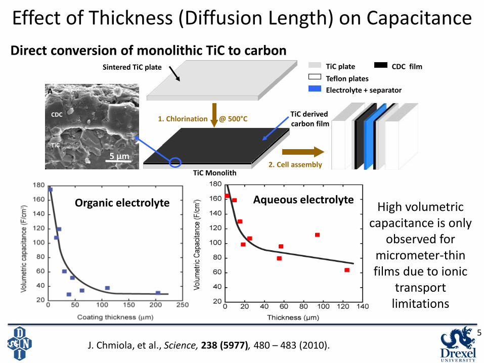
J. Chmiola, et al., Science, 238 (5977), 480 – 483 (2010).
Direct conversion of monolithic TiC to carbon
High volumetric capacitance is only
observed for micrometer-thin films due to ionic
transport limitations
Organic electrolyte Aqueous electrolyte
Effect of Thickness (Diffusion Length) on Capacitance
5

Coarse-Grained Carbide-Derived Carbons
75 µm
Cl2 (g): 800 ºC, 6 hours, 580 ml/min
H2 (g): 600 ºC, 2 hours, 120 ml/min
12 cm
100 µm
75 µm 250 µm
Electrode film
• Objective Reduce ball-milling of refractory
carbide precursor powders Characterize and analyze CDCs
synthesized from abrasive TiC
• Approach 75 µm, 250 µm TiC particles Standard tube furnace synthesis Powders with similar bulk properties
as typical CDCs
B. Dyatkin, et al. Journal of Power Sources, 306, 32 – 41 (2016). 6

Structure, Porosity, and Composition
1 2 3 4 5 60.0
0.2
0.4
0.6
0.8
1.0
dV
/dr
/ cc n
m-1 g
-1
Pore Diameter / nm
YP50
Coarse-Grained
CDC
1 2 3 40.0
0.2
0.4
0.6
0.8
1.0
Large CDC
(300 m)
Initial CDC (75 m)
dV
dr-1
/ c
c n
m-1 g
-1
Pore Diameter / nm
Milled CDC
200 300 400 500 600 7000
20
40
60
80
100
Temperature / C
Rem
ain
ing
Mass / %
0.0
0.3
0.6
0.9
1.2
1.5
1.8
dT
G / %
C
-1
1000 1500 2000 2500 3000
D+G2D
G
Norm
aliz
ed R
am
an Inte
nsity
Raman Shift / cm-1
D
Coarse-Grained CDC
CDC Micropowder• Microporous structure High porosity: 1830 m2/g, 0.78 cm3/g Nanostructured, well-ordered pores (dav = 7.8 Å) Similar porosity as CDC micropowders and activated
carbon
• Total conversion (99.5+%) • Graphitization resembles comparable CDCs
B. Dyatkin, et al. Journal of Power Sources, 306, 32 – 41 (2016). 7

Particle Structure
3 6 9 12 15
-2
0
2
4
6
8
G(r
) /
Å-2
r / Å
75 m CDC
[002] Graphite
d-spacing
5, 6, 7 member rings
Micropowder CDC
0.01 0.1 10.01
0.1
1
10
100
1000
Inte
nsi
ty (
Q)
/ Å
2
CDC: 75 m powder
CDC: 20 nm powder
CDC: 1.0 m powder
Q / Å-1
• Short-range carbon ordering of coarse-grained CDCs closely resembles structure of micropowders
• Pore wall graphitization and ring structure independent of particle size
X-Ray PDF SANS
• Identical behaviors in Guinier regime (0.2 Å-1 < Q < 0.7 Å-1) Slit pore structures nearly identical
for coarse and nanosized CDCs
• Changes in Porod regime (low-Q) • Surface roughness and external
surface changes
B. Dyatkin, et al. Journal of Power Sources, 306, 32 – 41 (2016). 8

High Capacitance in Organic Electrolyte
10 100 10000
25
50
75
100
125
Sweep Rate / mV s-1
Ca
pa
cita
nce
/ F
g-1
0.0
0.2
0.4
0.6
0.8
1.0
Co
ars
e-G
rain
ed C
DC
: C
/C0Coarse-Grained
CDC
YP50
• High capacitance and rate handling of coarse-grained CDCs that exceeds micropowder performance
• High mass loading (6.23 mg/cm2) and electrode conductivity (0.16 S∙cm-1)
• High volumetric energy densities and high Csp even for 1 mm thick films! 1 10 100 1000
0
2
4
6
8
10
Are
al C
ap
acita
nce
/ F
cm
-2
Sweep Rate / mV s-1
1 mm thick
electrode
90 m thick electrode
250 m thick
electrode
0.0 0.5 1.0 1.5 2.0 2.5
-120
-60
0
60
120
72 µm
YP50: 10 mV s-1
Capacitance / F
g-1
Voltage / V
250 mV s-1
10 mV s-1
50 mV s-1
100 mV s-1
10 100 10000
25
50
75
100
125
Sweep Rate / mV s-1
Capa
citance / F
g-1
0.0
0.2
0.4
0.6
0.8
1.0
Co
ars
e-G
rain
ed C
DC
: C
/C0Coarse-Grained
CDC
YP50
Sweep Rate Csp: CDC
2 mV/s 134 F/g
20 mV/s 120 F/g
100 mV/s 111 F/g
1000 mV/s 59 F/g
B. Dyatkin, et al. Journal of Power Sources, 306, 32 – 41 (2016). 9
1.5 M [NEt4
+][BF4-]
in CH3CN

Particle Size and Solvent Effects: RTIL Electrolyte
B. Dyatkin, et al. Journal of Power Sources, 306, 32 – 41 (2016).
10 100 10000
30
60
90
120
150
Neat
[EMIm+][TFSI
-]
YP50 in neat [EMIm+][TFSI-]
Capacitance / F
g-1
Sweep Rate / mV s-1
50% [EMIm+][TFSI-] /
50% CH3CN
0 10 20 30 40 500
10
20
30
40
50
Solv. [EMm+][TFSI
-]
Neat [EMm+][TFSI
-]
-Im
(Z
) /
Ohm
s
Re(Z) / Ohms
Milled CDCInitial CDC
0 3 60
3
6
-Im
(Z
) / O
hm
s
Re(Z) / Ohms
0.0 0.5 1.0 1.5 2.0 2.5-150
-100
-50
0
50
100
150
YP50 in neat [EMIm+][TFSI-]
Ca
pa
cita
nce
/ F
g-1
Voltage / V
50%[EMIm+][TFSI-] /
50% CH3CN
Neat [EMIm+][TFSI-]
• Neat [EMIm+][TFSI-] ionic liquid exhibits high capacitance Added solvent improves ionic mobility Solvated [EMIm+][TFSI-] capacitance exceeds
100 F/g Coarse-grained pores show same solvated ion
dynamics in milled CDC (10 um particles) Neat [EMIm+][TFSI-] more mobile in micropowders
75 µm75 µm
10

Electrochemical Stability in Coarse-Grained Carbons
0.0 0.5 1.0 1.5 2.0 2.5 3.0
-0.8
-0.4
0.0
0.4
0.8
Curr
ent
/ m
A
Voltage / V
0 10 20 30 40 50 600
10
20
30
40
50
60
-Im
(Z)
(Ohm
s)
Re(Z) (Ohms)
Initial 75 m CDC
Cycled to 3.5 V
3 60
3
-Im
(Z)
(Oh
ms)
Re(Z) (Ohms)
• Extended Cyclability and Potential Window • Minimal external surface minimizes
breakdown in neat RTIL • Ion confinement increases voltage window
from 2.5 V to 3.1 V • Breakdown mostly inside pores
2 mV/s
0 2000 4000 6000 8000 100000
20
40
60
80
100
Capacitance / F
g-1
Cycle Numer
1.0 A/g
B. Dyatkin, et al. Journal of Power Sources, 306, 32 – 41 (2016). 11

CDCs With Larger Diameters
• High capacitance in 1.5 M [NEt4+][BF4
-] in CH3CN 250 µm films are ~1 particle thick; 16 mg/cm2 loading Minimal bulk diffusion limitation Even higher capacitance than 75 µm films of comparable thickness
10 100 10000
30
60
90
120
1.5
1.0
0.5
Are
al C
apacitance / F
cm
-2
Capacitance / F
g-1
Sweep Rate / mV s-1
300 m CDC
75 m CDC
2.0
0.0 0.5 1.0 1.5 2.0 2.5
-120
-80
-40
0
40
80
120 20 mV s-1
10 mV s-1
Capacitance / F
g-1
Voltage / V
50 mV s-1
100 mV s-1
75 m CDC,
250 m film
10 mV s-1
B. Dyatkin, et al. Journal of Power Sources, 306, 32 – 41 (2016). 12

Key Advantages of Coarse-Grained Carbon Electrodes
0.1 µm
2 µm
75 µm
1. Microporosity and high surface areas (over 1500 m2/g)
2. Less expensive electrode materials 3. High capacitance and voltage window 4. High film loading: films can be made as
thick as 1 mm (automotive, transportation)
BUT WHY?
0.0 V +2.5 V 0.0 V -2.5 V
Electrosorption dominated by local ion-ion rearrangement, not bulk diffusion
B. Dyatkin, et al. Journal of Power Sources, 306, 32 – 41 (2016). Richey, F., Dyatkin, B., et al. J. Am. Chem. Soc., 135, 12818 (2013).
13

Acknowledgements 1. Nanomaterials Group (Drexel)
- Prof. Yury Gogotsi
2. Materials Research Centre
- Oleksiy Gogotsi, Yulya Zozulya,
Bohdan Malinovskiy
3. Oak Ridge National Laboratory - Hsiu-Wen Wang, Katharine L. Page
4. Universite Toulouse - Prof. Patrice Simon
14
Thank you!
[email protected] http://nano.materials.drexel.edu
Funding: 1. Department of Energy Fluid Interface Reactions,
Structures and Transport (FIRST) Center 2. DOE SCGSR Research Fellowship