coast guard, dept. of homeland security pt. 56€¦ · · 2018-03-1856.01–2 incorporation by...
TRANSCRIPT

169
Coast Guard, Dept. of Homeland Security Pt. 56
working level, the calculated max-imum stress during test shall not ex-ceed 90 percent of the yield strength of the material at test temperature. The supporting structure shall be analyzed to verify its adequacy.
(b) In all cases where the tanks are mechanically stress relieved in place in the ship or barge and the tanks are de-signed to carry cargoes with a specific gravity less than 1.05, the ship or barge shall be shown to have adequate sta-bility and buoyancy, as well as strength to carry the excess weight of the tank during the stress relief proce-dure.
PART 56—PIPING SYSTEMS AND APPURTENANCES
Subpart 56.01—General
Sec. 56.01–1 Scope (replaces 100.1). 56.01–2 Incorporation by reference. 56.01–3 Power boiler external piping (Re-
places 100.1.1, 100.1.2, 111.6, 122.1, 132 and 133).
56.01–5 Adoption of ANSI (American Na-tional Standards Institute) Code B31.1 for pressure and power piping, and other standards.
56.01–10 Plan approval.
Subpart 56.04—Piping Classification
56.04–1 Scope. 56.04–2 Piping classification according to
service. 56.04–10 Other systems.
Subpart 56.07—Design
56.07–5 Definitions (modifies 100.2). 56.07–10 Design conditions and criteria
(modifies 101–104.7).
Subpart 56.10—Components
56.10–1 Selection and limitations of piping components (replaces 105 through 108).
56.10–5 Pipe.
Subpart 56.15—Fittings
56.15–1 Pipe joining fittings. 56.15–5 Fluid-conditioner fittings. 56.15–10 Special purpose fittings.
Subpart 56.20—Valves
56.20–1 General. 56.20–5 Marking (reproduces 107.2). 56.20–7 Ends. 56.20–9 Valve construction.
56.20–15 Valves employing resilient mate-rial.
56.20–20 Valve bypasses.
Subpart 56.25—Pipe Flanges, Blanks, Flange Facings, Gaskets, and Bolting
56.25–5 Flanges. 56.25–7 Blanks. 56.25–10 Flange facings. 56.25–15 Gaskets (reproduces 108.4). 56.25–20 Bolting.
Subpart 56.30—Selection and Limitations of Piping Joints
56.30–1 Scope (replaces 110 through 118). 56.30–3 Piping joints (reproduces 110). 56.30–5 Welded joints. 56.30–10 Flanged joints (modifies 104.5.1 (a)). 56.30–15 Expanded or rolled joints. 56.30–20 Threaded joints. 56.30–25 Flared, flareless, and compression
fittings. 56.30–27 Caulked joints. 56.30–30 Brazed joints. 56.30–35 Gasketed mechanical couplings. 56.30–40 Flexible pipe couplings of the com-
pression or slip-on type.
Subpart 56.35—Expansion, Flexibility and Supports
56.35–1 Pipe stress calculations (replaces 119.7).
56.35–10 Nonmetallic expansion joints (re-places 119.5.1).
56.35–15 Metallic expansion joints (replaces 119.5.1).
Subpart 56.50—Design Requirements Pertaining to Specific Systems
56.50–1 General (replaces 122.6 through 122.10).
56.50–10 Special gaging requirements. 56.50–15 Steam and exhaust piping. 56.50–20 Pressure relief piping. 56.50–25 Safety and relief valve escape pip-
ing. 56.50–30 Boiler feed piping. 56.50–35 Condensate pumps. 56.50–40 Blowoff piping (replaces 102.2.5 (d)). 56.50–45 Circulating pumps. 56.50–50 Bilge and ballast piping. 56.50–55 Bilge pumps. 56.50–57 Bilge piping and pumps, alternative
requirements. 56.50–60 Systems containing oil. 56.50–65 Burner fuel-oil service systems. 56.50–70 Gasoline fuel systems. 56.50–75 Diesel fuel systems. 56.50–80 Lubricating-oil systems. 56.50–85 Tank-vent piping. 56.50–90 Sounding devices. 56.50–95 Overboard discharges and shell con-
nections.
VerDate Aug<31>2005 13:25 Nov 13, 2008 Jkt 214189 PO 00000 Frm 00179 Fmt 8010 Sfmt 8010 Y:\SGML\214189.XXX 214189eben
thal
l on
PR
OD
1PC
60 w
ith C
FR

170
46 CFR Ch. I (10–1–08 Edition) § 56.01–1
56.50–96 Keel cooler installations. 56.50–97 Instrument, control and sampling
piping (modifies 122.3). 56.50–103 Fixed oxygen-acetylene distribu-
tion piping. 56.50–105 Low-temperature piping. 56.50–110 Diving support systems.
Subpart 56.60—Materials
56.60–1 Acceptable materials and specifica-tions (replaces 123 and Table 126.1 in ANSI-B31.1).
56.60–2 Limitations on materials. 56.60–3 Ferrous materials. 56.60–5 Steel (High temperature applica-
tions). 56.60–10 Cast iron and malleable iron. 56.60–15 Ductile iron. 56.60–20 Nonferrous materials. 56.60–25 Nonmetallic materials.
Subpart 56.65—Fabrication, Assembly and Erection
56.65–1 General (replaces 127 through 135.4).
Subpart 56.70—Welding
56.70–1 General. 56.70–3 Limitations. 56.70–5 Material. 56.70–10 Preparation (modifies 127.3). 56.70–15 Procedure. 56.70–20 Qualification, general.
Subpart 56.75—Brazing
56.75–5 Filler metal. 56.75–10 Joint clearance (reproduces 128.2.2). 56.75–15 Heating (reproduces 128.2.3). 56.75–20 Brazing qualification. 56.75–25 Detail requirements. 56.75–30 Pipe joining details.
Subpart 56.80—Bending and Forming
56.80–5 Bending. 56.80–10 Forming (reproduces 129.2). 56.80–15 Heat treatment of bends and formed
components.
Subpart 56.85—Heat Treatment of Welds
56.85–5 Heating and cooling method (repro-duces 131.1).
56.85–10 Preheating. 56.85–15 Postheat treatment.
Subpart 56.90—Assembly
56.90–1 General. 56.90–5 Bolting procedure. 56.90–10 Threaded piping (reproduces 135.4).
Subpart 56.95—Inspection
56.95–1 General (replaces 136).
56.95–5 Rights of access of marine inspec-tors.
56.95–10 Type and extent of examination re-quired.
Subpart 56.97—Pressure Tests
56.97–1 General (replaces 137). 56.97–5 Pressure testing of nonstandard pip-
ing system components. 56.97–25 Preparation for testing (reproduces
137.3). 56.97–30 Hydrostatic tests (reproduces 137.4). 56.97–35 Pneumatic tests (replaces 137.5). 56.97–38 Initial service leak test (reproduces
137.7). 56.97–40 Installation tests.
AUTHORITY: 33 U.S.C. 1321(j), 1509; 43 U.S.C. 1333; 46 U.S.C. 3306, 3703; E.O. 12234, 45 FR 58801, 3 CFR, 1980 Comp., p. 277; E.O. 12777, 56 FR 54757, 3 CFR, 1991 Comp., p. 351; Depart-ment of Homeland Security Delegation No. 0170.1.
SOURCE: CGFR 68–82, 33 FR 18843, Dec. 18, 1968, unless otherwise noted.
Subpart 56.01—General
NOTE: See § 50.15–10 for general adoption of standards of the ANSI (American National Standards Institute). The printing of por-tions of the ‘‘American National Standard Code for Pressure Piping, Power Piping,’’ ANSI-B31.1, is with the permission of the publisher, The American Society of Mechan-ical Engineers (ASME) International, Three Park Avenue, New York, N.Y. 10016–5990. The adoption of this standard ANSI-B31.1 for pressure piping and power piping is subject to specific limitations or modifications as described in this part. Those requirements in ANSI-B31.1 which are not referred to in this part are adopted without change. Table 56.01–5(a) sets forth a general reference to various paragraphs in ANSI-B31.1 which are limited, modified, or replaced by regulations in this part.
§ 56.01–1 Scope (replaces 100.1). (a) This part contains requirements
for the various ships’ and barges’ pip-ing systems and appurtenances.
(b) The respective piping systems in-stalled on ships and barges shall have the necessary pumps, valves, regula-tion valves, safety valves, relief valves, flanges, fittings, pressure gages, liquid level indicators, thermometers, etc., for safe and efficient operation of the vessel.
(c) Piping for industrial systems on mobile offshore drilling units need not fully comply with the requirements of
VerDate Aug<31>2005 13:25 Nov 13, 2008 Jkt 214189 PO 00000 Frm 00180 Fmt 8010 Sfmt 8010 Y:\SGML\214189.XXX 214189eben
thal
l on
PR
OD
1PC
60 w
ith C
FR

171
Coast Guard, Dept. of Homeland Security § 56.01–2
this part but must meet Subpart 58.60 of this subchapter.
[CGFR 68–82, 33 FR 18843, Dec. 18, 1968, as amended by CGD 73–251, 43 FR 56799, Dec. 4, 1978]
§ 56.01–2 Incorporation by reference. (a) Certain standards and specifica-
tions are incorporated by reference into this part with the approval of the Director of the Federal Register in ac-cordance with 5 U.S.C. 552(a). To en-force any edition other than the one listed in paragraph (b) of this section, notice of the change must be published in the FEDERAL REGISTER and the ma-terial made available to the public. All approved material is available from the sources indicated in paragraph (b) or at the National Archives and Records Ad-ministration (NARA). For information on the availability of this material at NARA, call 202–741–6030, or go to: http:// www.archives.gov/federallregister/ codeloflfederallregulations/ ibrllocations.html.
(b) The standards and specifications approved for incorporation by ref-erence in this part, and the sections af-fected are:
AMERICAN NATIONAL STANDARDS INSTITUTE (ANSI)
11 West 42nd Street, New York, NY 10036
ANSI B1.1–82 Unified Inch Screw Threads (UN and UNR Thread Form) ................................56.60–1; 56.25–20
ANSI B1.20.1–83 Pipe Threads, General Purpose (Inch) ................................56.60–1
ANSI B1.20.3–76 (reaffirmed 1982) Dryseal Pipe Threads (Inch) ...........56.60–1
ANSI B16.1–75 Cast Iron Flanges and Flanged Fittings, Class 25, 125, 250 and 800 ...............................56.60–1; 56.60–10
ANSI B16.3–85 Malleable Iron Thread-ed Fittings, Classes 150 and 300 .......56.60–1
ANSI B16.4–85 Cast Iron Threaded Fit-tings, Classes 125 and 250 ................56.60–1
ANSI B16.5–81 Pipe Flanges and Flanged Fittings ...56.25–20; 56.30–10; 56.60–
1 ANSI B16.9–86 Factory-Made Wrought
Steel Buttwelding Fittings.............56.60–1 ANSI B16.10–86 Face-to-Face and End-
to-End Dimensions of Ferrous Valves .............................................56.60–1
ANSI B16.11–80 Forged Steel Fittings, Socket-Welding and Threaded .......56.30–5;
56.60–1 ANSI B16.14–83 Ferrous Pipe Plugs,
Bushings, and Locknuts with Pipe Threads...........................................56.60–1
ANSI B16.15–85 Cast Bronze Threaded Fittings, Classes 125 and 250 ...........56.60–1
ANSI B16.18–84 Cast Copper Alloy Sol-der Joint Pressure Fittings ............56.60–1
ANSI B16.20–73 Ring-Joint Gaskets and Grooves for Steel Pipe Flanges VIII, Division 1, Pressure Vessels, 1986 with addenda .....56.15–1; 56.15–5; 56.15– 10; 56.25–5; 56.30–10; 56.30–30; 56.60–15; 56.60–
1; 56.95–10 Section IX, Welding and Brazing Qualifications, 1986 with addenda .................. 56.70–5; 56.70–20; 56.75–20; 56.0–1
ANSI B16.24–79 Bronze Pipe Flanges and Flanged Fittings, Class 150 and 300 ............................................56.60–1
ANSI B16.25–86 Buttwelding Ends ........56.60–1; 56.30–5; 56.70–10
ANSI B16.28–86 Wrought Steel Buttwelding Short Radius Elbows and Returns ....................................56.60–1
ANSI B16.29–86 Wrought Copper and Wrought Copper Alloy Solder Joint Drainage Fittings—DWV.......56.60–1
ANSI B16.34–88 Valves-Flanged, Threaded and Welding End...56.20–1; 56.60–
1 ANSI B16.42–87 Ductile Iron Pipe
Flanges and Flanged Fittings, Classes 150 and 300 ..........................56.60–1
ANSI B18.2.1–81 Square and Hex Bolts and Screws, Inch Series.....56.25–20; 56.60–1
ANSI B18.2.2–87 Square and Hex Nuts .......................................... 56.25–20; 56.60–1
ANSI B31.1–86 Power Piping .................56.01–5 ANSI B36.10M–85 Welded and Seamless
Wrought Steel Pipe ..........56.07–5; 56.30–20; 56.60–1
ANSI B36.19M–85 Stainless Steel Pipe ............................................56.07–5; 56.60–1
AMERICAN SOCIETY OF MECHANICAL ENGINEERS (ASME) INTERNATIONAL
Three Park Avenue, New York, NY 10016–5990
Boiler and Pressure Vessel Code:
Section I, Power Boilers, 1986 with addenda56.15–5; 56.15–10; 56.60–1; 56.60–1; 56.70–15; 56.95–10 56.15–1 Section VIII, Division 1, Pressure Vessels, 1986 with addenda ...56.15–1; 56.15– 5; 56.15–10; 56.25–5; 56.30–10; 56.30–30; 56.60–
15; 56.60–1; 56.95–10 Section IX, Welding and Brazing Qualifications, 1986 with addenda ............... 56.70–5; 56.70–20; 56.75–20; 56.85–10
AMERICAN SOCIETY FOR TESTING AND MATERIALS (ASTM)
100 Barr Harbor Drive, West Conshohocken, PA 19428–2959.
ASTM A 36/A 36M–97a, Standard Speci-fication for Carbon Structural Steel..............................................56.30–10
VerDate Aug<31>2005 13:25 Nov 13, 2008 Jkt 214189 PO 00000 Frm 00181 Fmt 8010 Sfmt 8010 Y:\SGML\214189.XXX 214189eben
thal
l on
PR
OD
1PC
60 w
ith C
FR

172
46 CFR Ch. I (10–1–08 Edition) § 56.01–2
ASTM A 47–90 (1995), Standard Speci-fication for Ferritic Malleable Iron Castings ..........................................56.60–1
ASTM A 53–98, Standard Specification for Pipe, Steel, Black and Hot- Dipped, Zinc-Coated, Welded and Seamless .............................56.10–5; 56.60–1
ASTM A 106–95, Standard Specifica-tion for Seamless Carbon Steel Pipe for High-Temperature Service ........................................................56.60–1
ASTM A 126–95, Standard Specifica-tion for Gray Iron Castings for Valves, Flanges, and Pipe Fittings ........................................................56.60–1
ASTM A 134–96, Standard Specifica-tion for Pipe, Steel, Electric-Fu-sion (Arc)-Welded (Sizes NPS 16 and Over) ........................................56.60–1
ASTM A 135–97c, Standard Specifica-tion for Electric-Resistance-Weld-ed Steel Pipe...................................56.60–1
ASTM A 139–96, Standard Specifica-tion for Electric-Fusion (Arc)- Welded Steel Pipe (NPS 4 and Over) ...............................................56.60–1
ASTM A 178/A 178M–95, Standard Spec-ification for Electric-Resistance- Welded Carbon Steel and Carbon- Manganese Steel Boiler and Super-heater Tubes ...................................56.60–1
ASTM A 179/A 179M–90a (1996), Stand-ard Specification for Seamless Cold-Drawn Low-Carbon Steel Heat-Exchanger and Condenser Tubes ..............................................56.60–1
ASTM A 182/A 182M–97c, Standard Specification for Forged or Rolled Alloy-Steel Pipe Flanges, Forged Fittings, and Valves and Parts for High-Temperature Service ..........56.50–105
ASTM A 192/A 192M–91 (1996), Standard Specification for Seamless Carbon Steel Boiler Tubes for High-Pres-sure Service ....................................56.60–1
ASTM A 194/A 194M–98b, Standard Specification for Carbon and Alloy Steel Nuts for Bolts for High Pres-sure or High Temperature Service, or Both.........................................56.50–105
ASTM A 197–87 (1992), Standard Speci-fication for Cupola Malleable Iron ........................................................56.60–1
ASTM A 210/A 210M–96, Standard Spec-ification for Seamless Medium- Carbon Steel Boiler and Super-heater Tubes ...................................56.60–1
ASTM A 213/A 213M–95a, Standard Specification for Seamless Fer-ritic and Austenitic Alloy-Steel Boiler, Superheater, and Heat-Ex-changer Tubes.................................56.60–1
ASTM A 214/A 214M–96, Standard Spec-ification for Electric-Resistance- Welded Carbon Steel Heat-Ex-changer and Condenser Tubes.........56.60–1
ASTM A 226/A 226M–95, Standard Spec-
ification for Electric-Resistance- Welded Carbon Steel Boiler and Superheater Tubes for High-Pres-sure Service ....................................56.60–1
ASTM A 234/A 234M–97, Standard Spec-ification for Piping Fittings of Wrought Carbon Steel and Alloy Steel for Moderate and High Tem-perature Service .............................56.60–1
ASTM A 249/A 249M–96a, Standard Specification for Welded Aus-tenitic Steel Boiler, Superheater, Heat-Exchanger, and Condenser Tubes ..............................................56.60–1
ASTM A 268/A 268M–96, Standard Spec-ification for Seamless and Welded Ferritic and Martensitic Stainless Steel Tubing for General Service ........................................................56.60–1
ASTM A 276–98, Standard Specifica-tion for Stainless Steel Bars and Shapes ............................................56.60–2
ASTM A 307–97, Standard Specifica-tion for Carbon Steel Bolts and Studs, 60,000 PSI Tensile Strength ...................................................... 56.25–20
ASTM A 312/A 312M–95a, Standard Specification for Seamless and Welded Austenitic Stainless Steel Pipes ................................56.50–105; 56.60–1
ASTM A 320/A 320M–97, Standard Spec-ification for Alloy/Steel Bolting Materials for Low-Temperature Service.........................................56.50–105
ASTM A 333/A 333M–94, Standard Spec-ification for Seamless and Welded Steel Pipe for Low-Temperature Service.............................56.50–105; 56.60–1
ASTM A 334/A 334M–96, Standard Spec-ification for Seamless and Welded Carbon and Alloy-Steel Tubes for Low-Temperature Service ..........56.50–105;
56.60–1 ASTM A 335/A 335M–95a, Standard
Specification for Seamless Fer-ritic Alloy-Steel Pipe for High- Temperature Service ......................56.60–1
ASTM A 350/A 350M–97, Standard Spec-ification for Carbon and Low-Alloy Steel Forgings, Requiring Notch Toughness Testing for Piping Components .................................56.50–105
ASTM A 351/A 351M–94a, Standard Specification for Castings, Aus-tenitic, Austenitic-Ferritic (Du-plex), for Pressure-Containing Parts ............................................56.50–105
ASTM A 352/A 352M–93 (1998), Standard Specification for Steel Castings, Ferritic and Martensitic, for Pres-sure-Containing Parts, Suitable for Low-Temperature Service......56.50–105
ASTM A 358/A 358M–95a, Standard Specification for Electric-Fusion- Welded Austenitic Chromium- Nickel Alloy Steel Pipe for High- Temperature Service ......................56.60–1
VerDate Aug<31>2005 13:25 Nov 13, 2008 Jkt 214189 PO 00000 Frm 00182 Fmt 8010 Sfmt 8010 Y:\SGML\214189.XXX 214189eben
thal
l on
PR
OD
1PC
60 w
ith C
FR

173
Coast Guard, Dept. of Homeland Security § 56.01–2
ASTM A 369/A 369M–92, Standard Spec-ification for Carbon and Ferritic Alloy Steel Forged and Bored Pipe for High-Temperature Service ........56.60–1
ASTM A 376/A 376M–96, Standard Spec-ification for Seamless Austenitic Steel Pipe for High-Temperature Central-Station Service ...56.07–10; 56.60–1;
56.60–2 ASTM A 395/A 395M–98, Standard Spec-
ification for Ferritic Ductile Iron Pressure-Retaining Castings for Use at Elevated Temperatures .....56.50–60;
56.60–1; 56.60–15 ASTM A 403/A 403M–98, Standard Spec-
ification for Wrought Austenitic Stainless Steel Piping Fittings ......56.60–1
ASTM A 420/A 420M–96a, Standard Specification for Piping Fittings of Wrought Carbon Steel and Alloy Steel for Low-Temperature Serv-ice ....................................56.50–105; 56.60–1
ASTM A 520–97, Standard Specifica-tion for Supplementary Require-ments for Seamless and Electric- Resistance-Welded Carbon Steel Tubular Products for High-Tem-perature Service Conforming to ISO Recommendations for Boiler Construction...................................56.60–1
ASTM A 522/A 522M–95b, Standard Specification for Forged or Rolled 8 and 9% Nickel Alloy Steel Flanges, Fittings, Valves, and Parts for Low-Temperature Serv-ice ................................................56.50–105
ASTM A 536–84 (1993), Standard Speci-fication for Ductile Iron Castings ........................................................56.60–1
ASTM A 575–96, Standard Specifica-tion for Steel Bars, Carbon, Mer-chant Quality, M-Grades ................56.60–2
ASTM A 576–90b (1995), Standard Spec-ification for Steel Bars, Carbon, Hot-Wrought, Special Quality ........56.60–2
ASTM B 16–92, Standard Specification for Free-Cutting Brass Rod, Bar, and Shapes for Use in Screw Ma-chines .............................................56.60–2
ASTM B 21–96, Standard Specification for Naval Brass Rod, Bar, and Shapes ............................................56.60–2
ASTM B 26/B 26M–97, Standard Speci-fication for Aluminum-Alloy Sand Castings ..........................................56.60–2
ASTM B 42–96, Standard Specification for Seamless Copper Pipe, Stand-ard Sizes .........................................56.60–1
ASTM B 43–96, Standard Specification for Seamless Red Brass Pipe, Standard Sizes ................................56.60–1
ASTM B 68–95, Standard Specification for Seamless Copper Tube, Bright Annealed.........................................56.60–1
ASTM B 75–97, Standard Specification for Seamless Copper Tube...............56.60–1
ASTM B 85–96, Standard Specification
for Aluminum-Alloy Die Castings ........................................................56.60–2
ASTM B 88–96, Standard Specification for Seamless Copper Water Tube ........................................................56.60–1
ASTM B 96–93, Standard Specification for Copper-Silicon Alloy Plate, Sheet, Strip, and Rolled Bar for General Purposes and Pressure Vessels ............................................56.60–2
ASTM B 111–95, Standard Specifica-tion for Copper and Copper-Alloy Seamless Condenser Tubes and Ferrule Stock .................................56.60–1
ASTM B 124–96, Standard Specifica-tion for Copper and Copper Alloy Forging Rod, Bar, and Shapes ........56.60–2
ASTM B 161–93, Standard Specifica-tion for Nickel Seamless Pipe and Tube................................................56.60–1
ASTM B 165–93, Standard Specifica-tion of Nickel-Copper Alloy (UNS NO4400) Seamless Pipe and Tube ........................................................56.60–1
ASTM B 167–97a, Standard Specifica-tion for Nickel-Chromium-Iron Al-loys (UNS NO6600, NO6601, NO6603, NO6690, NO6025, and NO6045) Seam-less Pipe and Tube ..........................56.60–1
ASTM B 171–95, Standard Specifica-tion for Copper-Alloy Plate and Sheet for Pressure Vessels, Con-densers, and Heat Exchangers ........56.60–2
ASTM B 210–95, Standard Specifica-tion for Aluminum and Alu-minum-Alloy Drawn Seamless Tubes ..............................................56.60–1
ASTM B 234–95, Standard Specifica-tion for Aluminum and Alu-minum-Alloy Drawn Seamless Tubes for Condensers and Heat Ex-changers .........................................56.60–1
ASTM B 241/B 241M–96, Standard Spec-ification for Aluminum and Alu-minum-Alloy Seamless Pipe and Seamless Extruded Tube ................56.60–1
ASTM B 280–97, Standard Specifica-tion for Seamless Copper Tube for Air Conditioning and Refrigera-tion Field Service ...........................56.60–1
ASTM B 283–96, Standard Specifica-tion for Copper and Copper-Alloy Die Forgings (Hot-Pressed).............56.60–2
ASTM B 315–93, Standard Specifica-tion for Seamless Copper Alloy Pipe and Tube .................................56.60–1
ASTM B 361–95, Standard Specifica-tion for Factory-Made Wrought Aluminum and Aluminum-Alloy Welding Fittings.............................56.60–1
ASTM B 858M–95, Standard Test Meth-od for Determination of Suscepti-bility to Stress Corrosion Crack-ing in Copper Alloys Using an Am-monia Vapor Test ...........................56.60–2
ASTM D 635–97, Standard Test Method for Rate of Burning and/or Extent
VerDate Aug<31>2005 13:25 Nov 13, 2008 Jkt 214189 PO 00000 Frm 00183 Fmt 8010 Sfmt 8010 Y:\SGML\214189.XXX 214189eben
thal
l on
PR
OD
1PC
60 w
ith C
FR

174
46 CFR Ch. I (10–1–08 Edition) § 56.01–2
and Time of Burning of Plastics in a Horizontal Position ....................56.60–25
ASTM D 1785–96b, Standard Specifica-tion for Poly (Vinyl Chlo-ride)(PVC) Plastic Pipe, Schedules 40, 80, and 120 .................................56.60–25
ASTM D 2241–96b, Standard Specifica-tion for Poly (Vinyl Chlo-ride)(PVC) Pressure-Rated Pipe (SDR Series)..................................56.60–25
ASTM D 2464–96a, Standard Specifica-tion for Threaded Poly (Vinyl Chloride)(PVC) Plastic Pipe Fit-tings Schedule 80...........................56.60–25
ASTM D 2466–97, Standard Specifica-tion for Poly (Vinyl Chlo-ride)(PVC) Plastic Pipe Fittings, Schedule 40....................................56.60–25
ASTM D 2467–96a, Standard Specifica-tion for Poly (Vinyl Chlo-ride)(PVC) Plastic Pipe Fittings, Schedule 80....................................56.60–25
ASTM D 2665–97b, Standard Specifica-tion for Poly (Vinyl Chlo-ride)(PVC)Plastic Drain, Waste, and Vent Pipe and Fittings ...........56.60–25
ASTM D 2863–95, Standard Test Meth-od for Measuring the Minimum Oxygen Concentration to Support Candle-like Combustion of Plas-tics (Oxygen Index) .......................56.60–25
ASTM E 23–96, Standard Test Methods for Notched Bar Impact Testing of Metallic Materials .......................56.50–105
ASTM F 682–82a (1993), Standard Spec-ification for Wrought Carbon Steel Sleeve-Type Pipe Couplings............56.60–1
ASTM F 1006–86 (1992), Standard Speci-fication for Entrainment Separa-tors for Use in Marine Piping Ap-plications........................................56.60–1
ASTM F 1007–86 (1996), Standard Speci-fication for Pipe-Line Expansion Joints of the Packed Slip Type for Marine Application.........................56.60–1
ASTM F 1020–86 (1996), Standard Speci-fication for Line-Blind Valves for Marine Applications .......................56.60–1
ASTM F 1120–87 (1993), Standard Speci-fication for Circular Metallic Bel-lows Type Expansion Joints for Piping Applications ........................56.60–1
ASTM F 1123–87 (1993), Standard Speci-fication for Non-Metallic Expan-sion Joints ......................................56.60–1
ASTM F 1139–88 (1993), Standard Speci-fication for Steam Traps and Drains .............................................56.60–2
ASTM F 1172–88 (1993), Standard Speci-fication for Fuel Oil Meters of the Volumetric Positive Displacement Type................................................56.60–1
ASTM F 1173–95, Standard Specifica-tion for Thermosetting Resin Fi-berglass Pipe and Fittings to be Used for Marine Applications .........56.60–1
ASTM F 1199–88 (1993), Standard Speci-
fication for Cast (All Temperature and Pressures) and Welded Pipe Line Strainers (150 psig and 150 De-grees F Maximum)..........................56.60–1
ASTM F 1200–88 (1993), Standard Speci-fication for Fabricated (Welded) Pipe Line Strainers (Above 150 psig and 150 Degrees F) ...................56.60–1
ASTM F 1201–88 (1993), Standard Speci-fication for Fluid Conditioner Fit-tings in Piping Applications above 0 Degrees F .....................................56.60–1
ASTM F 1387–93, Standard Specifica-tion for Performance of Mechani-cally Attached Fittings.................56.30–25
ASTM F 1476–95a, Standard Specifica-tion for Performance of Gasketed Mechanical Couplings for Use in Piping Applications.......................56.30–35
ASTM F 1548–94, Standard Specifica-tion for the Performance of Fit-tings for Use with Gasketed Me-chanical Couplings, Used in Piping Applications ..................................56.30–35
EXPANSION JOINT MANUFACTURERS ASSOCIATION INC. (EJMA)
25 North Broadway, Tarrytown, NY 10591
Standards of the Expansion Joint Manufacturers Association, 1980.....56.60–1
INTERNATIONAL MARITIME ORGANIZATION (IMO), PUBLICATIONS SECTION,
4 Albert Embankment, London, SE1 7SR United Kingdom
Resolution A.753(18) Guidelines for the Application of Plastic Pipes on Ships .............................................56.60–25
FLUID CONTROLS INSTITUTE INC. (FCI)
31 South Street, Suite 303, Morristown, NJ 07960
FCI 69–1 Pressure Rating Standard for Steam Traps ...................................56.60–1
MANUFACTURERS STANDARDIZATION SOCIETY OF THE VALVE AND FITTINGS INDUSTRY, INC. (MSS)
127 Park Street NE, Vienna, VA 22180
SP–6–85 Standard Finishes for Contact Faces of Pipe Flanges and Con-necting-End Flanges of Valves and Fittings .............................56.25–10; 56.60–1
SP–9–87 Spot Facing for Bronze, Iron and Steel Flanges ...........................56.60–1
SP–25–88 Standard Marking System for Valves, Fittings, Flanges and Unions.....................56.15–1; 56.20–5; 56.60–1
SP–44–85 Steel Pipe Line Flanges .........56.60–1 SP–45–87 Bypass and Drain Connection
Standard............................56.20–20; 56.60–1 SP–51–86 Class 150LW Corrosion Re-
sistant Cast Flanges and Flanged Fittings ..........................................56.60–1
VerDate Aug<31>2005 13:25 Nov 13, 2008 Jkt 214189 PO 00000 Frm 00184 Fmt 8010 Sfmt 8010 Y:\SGML\214189.XXX 214189eben
thal
l on
PR
OD
1PC
60 w
ith C
FR

175
Coast Guard, Dept. of Homeland Security § 56.01–5
SP–53–85 Quality Standard for Steel Castings and Forgings for Valves, Flanges and Fittings and Other Piping Components—Magnetic Particle Examination Method ........56.60–1
SP–55–85 Quality Standard for Steel Castings for Valves, Flanges and Fittings and Other Piping Compo-nents—Visual Method.....................56.60–1
SP–58–83 Pipe Hangers and Supports— Materials, Design and Manufac-ture.................................................56.60–1
SP–61–85 Pressure Testing of Steel Valves .............................................56.60–1
SP–67–83 Butterfly Valves.....................56.60–1 SP–69–83 Pipe Hangers and Supports—
Selection and Application ..............56.60–1 SP–72–87 Ball Valves with Flanged or
Butt-Welding Ends for General Service............................................56.60–1
SP–73–86 Brazing Joints for Wrought and Cast Copper Alloy Solder Joint Pressure Fittings ..................56.60–1
SP–83–87 Steel Pipe Unions, Socket- Welding and Threaded ....................56.60–1
SOCIETY OF AUTOMOTIVE ENGINEERS (SAE)
400 Commonwealth Drive, Warrendale, Pa 15096
J1475–84 Hydraulic Hose Fittings for Marine Applications......................56.60–25
J1942–89 Hose and Hose Assemblies for Marine Applications......................56.60–25
[CGD 77–140, 54 FR 40599, Oct. 2, 1989; 55 FR 39968, Oct. 1, 1990, as amended by CGD 88–032, 56 FR 35822, July 29, 1991; CGD 95–012, 60 FR 48049, Sept. 18, 1995; CGD 95–027, 61 FR 26000, May 23, 1996; CGD 96–041, 61 FR 50728, Sept. 27, 1996; CGD 97–057, 62 FR 51044, Sept. 30, 1997; CGD 95–028, 62 FR 51200, Sept. 30, 1997; USCG–1999–6216, 64 FR 53224, Oct. 1, 1999; USCG–1999–5151, 64 FR 67178, Dec. 1, 1999; USCG–2004–18884, 69 FR 58346, Sept. 30, 2004]
§ 56.01–3 Power boiler external piping (Replaces 100.1.1, 100.1.2, 111.6, 122.1, 132 and 133).
(a) Power boiler external piping and components must meet the require-ments of this part and §§ 52.01–105, 52.01– 110, 52.01–115, and 52.01–120 of this chap-ter.
(b) Specific requirements for power boiler external piping and appur-tenances, as defined in §§ 100.1.1 and 100.1.2, appearing in the various para-graphs of ANSI B31.1, are not adopted unless specifically indicated elsewhere in this part.
[CGD 77–140, 54 FR 40602, Oct. 2, 1989; 55 FR 39968, Oct. 1, 1990]
§ 56.01–5 Adoption of ANSI (American National Standards Institute) Code B31.1 for pressure and power pip-ing, and other standards.
(a) Piping systems for ships and barges shall be designed, constructed, and inspected in accordance with B31.1, the ‘‘Code for Pressure Piping, Power Piping,’’ of the ANSI (American Na-tional Standards Institute), as limited, modified, or replaced by specific re-quirements in this part. The provisions in the appendices to ANSI-B31.1 are adopted and shall be followed when the requirements in ANSI-B31.1 or the reg-ulations in this part make them man-datory. For general information Table 56.01–5(a) lists the various paragraphs, etc., in ANSI-B31.1 which are limited, modified, replaced, or reproduced by regulations in this part.
TABLE 56.01–5(A)—LIMITATIONS AND MODIFICA-TIONS IN THE ADOPTION OF ANSI-B31.1 CODE FOR PRESSURE AND POWER PIPING
Section or paragraph in ANSI- B31.1, and disposition Unit in this part
100.1 replaced by ........................... 56.01–1. 100.2 modified by ........................... 56.07–5. 101 through 104.7 modified by ...... 56.07–10. 101.2 modified by ........................... 56.07–10(a), (b). 101.5 replaced by ........................... 56.07–10(c). 102.2 modified by ........................... 56.07–10(d). 102.2.5(d) replaced by ................... 56.50–40. 102.3 and 104.1.2 modified by ....... 56.07–10(e). 104.3 modified by ........................... 56.07–10(f). 104.4 modified by ........................... 56.07–10(e). 104.5.1 modified by ........................ 56.30–10. 105 through 108 replaced by ......... 56.10–1 through 56.25–
20. 110 through 118 replaced by ......... 56.30–1 through 56.30–
35. 119.5.1 replaced by ........................ 56.35–10, 56.35–15,
56.35–35. 119.7 replaced by ........................... 56.35–1. 122.3 modified by ........................... 56.50–97. 122.6 through 122.10 replaced by 56.50–1 through 56.50–
80. 123 replaced by .............................. 56.60–1. Table 126.1 is replaced by ............. 56.30–5(c)(3), 56.60–1. 127 through 135.4 replaced by ...... 56.65–1, 56.70–1
through 56.90–10. 136 replaced by .............................. 56.95–1 through 56.95–
10. 137 replaced by .............................. 56.97–1 through 56.97–
40.
(b) When a section or paragraph of the regulations in this part relates to material in ANSI-B31.1 Code (American National Standard Code for Pressure Piping, Power Piping), the relationship with this code will be shown imme-diately following the heading of the
VerDate Aug<31>2005 13:25 Nov 13, 2008 Jkt 214189 PO 00000 Frm 00185 Fmt 8010 Sfmt 8010 Y:\SGML\214189.XXX 214189eben
thal
l on
PR
OD
1PC
60 w
ith C
FR
176
46 CFR Ch. I (10–1–08 Edition) § 56.01–10
section or at the beginning of the para-graph as follows:
(1) (Modifies lll.) This indicates that the material in the ANSI-B31.1 so numbered for identification is gen-erally applicable but is being altered, amplified or augmented.
(2) (Replaces lll.) This indicates that the material in the ANSI-B31.1 so numbered for identification does not apply.
(3) (Reproduces lll.) This indicates that the material in the ANSI-B31.1 so numbered for identification is being identically reproduced for convenience, not for emphasis.
(c) As stated in § 50.15–10 of this chap-ter, the standards of the ANSI (Amer-ican National Standards Institute) spe-cifically referred to in this part shall be the governing requirements for the subject matters covered unless specifi-cally limited, modified or replaced by other regulations in this subchapter. See § 56.60–1(b) for the other adopted commercial standards applicable to piping systems which also form a part of this subchapter.
[CGFR 68–82, 33 FR 18843, Dec. 18, 1968, as amended by CGFR 69–127, 35 FR 9978, June 17, 1970; CGFR 72–59R, 37 FR 6189, Mar. 25, 1972; CGD 73–254, 40 FR 40164, Sept. 2, 1975; CGD 77– 140, 54 FR 40602, Oct. 2, 1989]
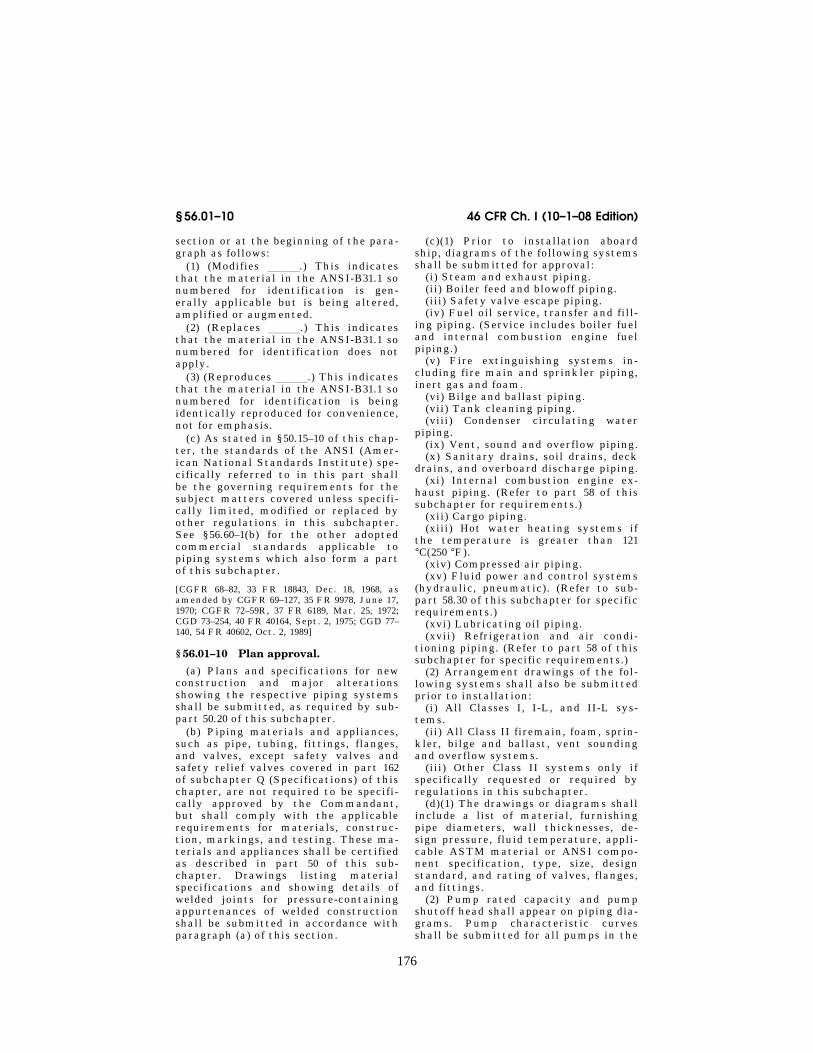
§ 56.01–10 Plan approval.
(a) Plans and specifications for new construction and major alterations showing the respective piping systems shall be submitted, as required by sub-part 50.20 of this subchapter.
(b) Piping materials and appliances, such as pipe, tubing, fittings, flanges, and valves, except safety valves and safety relief valves covered in part 162 of subchapter Q (Specifications) of this chapter, are not required to be specifi-cally approved by the Commandant, but shall comply with the applicable requirements for materials, construc-tion, markings, and testing. These ma-terials and appliances shall be certified as described in part 50 of this sub-chapter. Drawings listing material specifications and showing details of welded joints for pressure-containing appurtenances of welded construction shall be submitted in accordance with paragraph (a) of this section.
(c)(1) Prior to installation aboard ship, diagrams of the following systems shall be submitted for approval:
(i) Steam and exhaust piping. (ii) Boiler feed and blowoff piping. (iii) Safety valve escape piping. (iv) Fuel oil service, transfer and fill-
ing piping. (Service includes boiler fuel and internal combustion engine fuel piping.)
(v) Fire extinguishing systems in-cluding fire main and sprinkler piping, inert gas and foam.
(vi) Bilge and ballast piping. (vii) Tank cleaning piping. (viii) Condenser circulating water
piping. (ix) Vent, sound and overflow piping. (x) Sanitary drains, soil drains, deck
drains, and overboard discharge piping. (xi) Internal combustion engine ex-
haust piping. (Refer to part 58 of this subchapter for requirements.)
(xii) Cargo piping. (xiii) Hot water heating systems if
the temperature is greater than 121 °C(250 °F).
(xiv) Compressed air piping. (xv) Fluid power and control systems
(hydraulic, pneumatic). (Refer to sub-part 58.30 of this subchapter for specific requirements.)
(xvi) Lubricating oil piping. (xvii) Refrigeration and air condi-
tioning piping. (Refer to part 58 of this subchapter for specific requirements.)
(2) Arrangement drawings of the fol-lowing systems shall also be submitted prior to installation:
(i) All Classes I, I-L, and II-L sys-tems.
(ii) All Class II firemain, foam, sprin-kler, bilge and ballast, vent sounding and overflow systems.
(iii) Other Class II systems only if specifically requested or required by regulations in this subchapter.
(d)(1) The drawings or diagrams shall include a list of material, furnishing pipe diameters, wall thicknesses, de-sign pressure, fluid temperature, appli-cable ASTM material or ANSI compo-nent specification, type, size, design standard, and rating of valves, flanges, and fittings.
(2) Pump rated capacity and pump shutoff head shall appear on piping dia-grams. Pump characteristic curves shall be submitted for all pumps in the
VerDate Aug<31>2005 13:25 Nov 13, 2008 Jkt 214189 PO 00000 Frm 00186 Fmt 8010 Sfmt 8010 Y:\SGML\214189.XXX 214189eben
thal
l on
PR
OD
1PC
60 w
ith C
FR
177
Coast Guard, Dept. of Homeland Security § 56.04–2
firemain and foam systems. These curves need not be submitted if the fol-lowing information is shown on the drawing:
(i) Rated capacity and head at rated capacity.
(ii) Shutoff head. (iii) Head at 150 percent rated capac-
ity. (3) Standard drawings of the fol-
lowing fabrication details shall be sub-mitted:
(i) Welding details for piping connec-tions.
(ii) Welding details for nonstandard fittings (when appropriate).
(d–1) Plans of piping for industrial systems on mobile offshore drilling units must be submitted under subpart 58.60 of this subchapter.
(e) Where piping passes through wa-tertight bulkheads and/or fire bound-aries, plans of typical details of piping penetrations shall be submitted.
(f) Arrangement drawings specified in paragraph (c)(2) of this section are not required if—
(1) The location of each component for which there is a location require-ment (i.e., shell penetration, fire sta-tion, foam monitor, etc.) is indicated on the piping diagram;
(2) The diagram includes, or is ac-companied by and makes reference to,
a material schedule which describes components in sufficient detail to sub-stantiate their compliance with the regulations of this subchapter;
(3) A thermal stress analysis is not required; and
(4) A dynamic analysis is neither re-quired nor elected in lieu of allowable stress reduction.
[CGFR 68–82, 33 FR 18843, Dec. 18, 1968, as amended by CGFR 69–127, 35 FR 9978, June 17, 1970; CGFR 72–59R, 37 FR 6189, Mar. 25, 1972; CGD 73–251, 43 FR 56799, Dec. 4, 1978, CGD 77– 140, 54 FR 40602, Oct. 2, 1989; CGD 95–012, 60 FR 48049, Sept. 18, 1995]
Subpart 56.04—Piping Classification
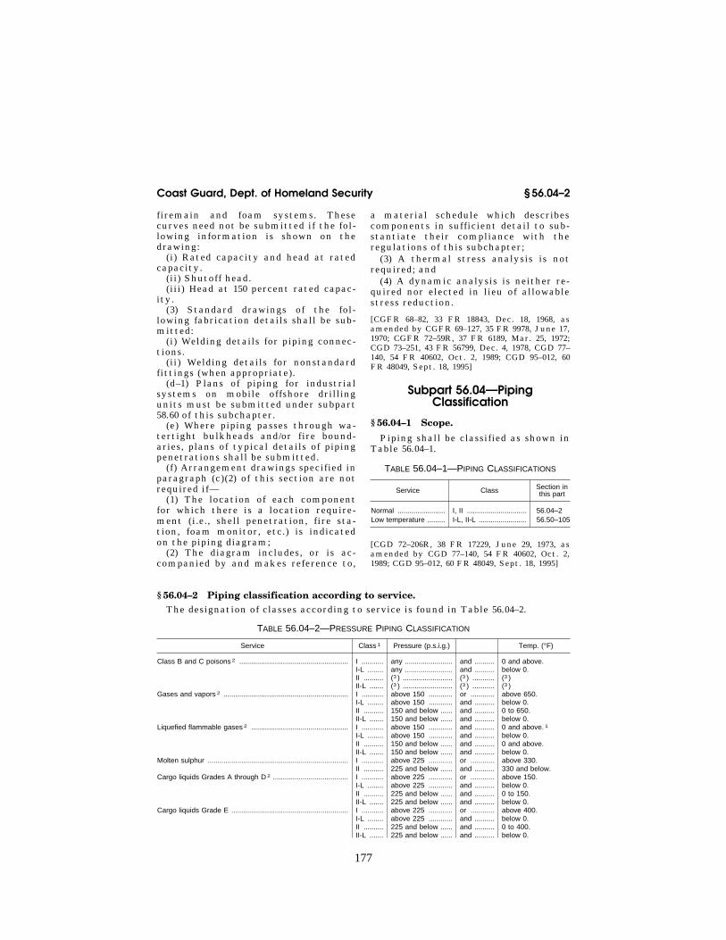
§ 56.04–1 Scope.
Piping shall be classified as shown in Table 56.04–1.
TABLE 56.04–1—PIPING CLASSIFICATIONS
Service Class Section in this part
Normal ........................ I, II .............................. 56.04 –2 Low temperature ......... I-L, II-L ........................ 56.50 –105
[CGD 72–206R, 38 FR 17229, June 29, 1973, as amended by CGD 77–140, 54 FR 40602, Oct. 2, 1989; CGD 95–012, 60 FR 48049, Sept. 18, 1995]
§ 56.04–2 Piping classification according to service. The designation of classes according to service is found in Table 56.04–2.
TABLE 56.04–2—PRESSURE PIPING CLASSIFICATION
Service Class 1 Pressure (p.s.i.g.) Temp. (°F)
Class B and C poisons 2 ....................................................... I ........... any ........................ and .......... 0 and above. I-L ........ any ........................ and .......... below 0. II .......... (3 ) ......................... (3 ) ........... (3 ) II-L ....... (3 ) ......................... (3 ) ........... (3 )
Gases and vapors 2 ............................................................... I ........... above 150 ............ or ............ above 650. I-L ........ above 150 ............ and .......... below 0. II .......... 150 and below ...... and .......... 0 to 650. II-L ....... 150 and below ...... and .......... below 0.
Liquefied flammable gases 2 ................................................. I ........... above 150 ............ and .......... 0 and above. 1 I-L ........ above 150 ............ and .......... below 0. II .......... 150 and below ...... and .......... 0 and above. II-L ....... 150 and below ...... and .......... below 0.
Molten sulphur ....................................................................... I ........... above 225 ............ or ............ above 330. II .......... 225 and below ...... and .......... 330 and below.
Cargo liquids Grades A through D 2 ...................................... I ........... above 225 ............ or ............ above 150. I-L ........ above 225 ............ and .......... below 0. II .......... 225 and below ...... and .......... 0 to 150. II-L ....... 225 and below ...... and .......... below 0.
Cargo liquids Grade E ........................................................... I ........... above 225 ............ or ............ above 400. I-L ........ above 225 ............ and .......... below 0. II .......... 225 and below ...... and .......... 0 to 400. II-L ....... 225 and below ...... and .......... below 0.
VerDate Aug<31>2005 13:25 Nov 13, 2008 Jkt 214189 PO 00000 Frm 00187 Fmt 8010 Sfmt 8010 Y:\SGML\214189.XXX 214189eben
thal
l on
PR
OD
1PC
60 w
ith C
FR

178
46 CFR Ch. I (10–1–08 Edition) § 56.04–10
TABLE 56.04–2—PRESSURE PIPING CLASSIFICATION—Continued
Service Class 1 Pressure (p.s.i.g.) Temp. (°F)
Water ..................................................................................... I ........... above 225 ............ or ............ above 350. II .......... 225 and below ...... and .......... 350 and below.
Fuels (Bunker, diesel, gasoline, etc.) .................................... I ........... above 150 ............ or ............ above 150. II .......... 150 and below ...... and .......... 150 and below.
Lubricating oil ........................................................................ I ........... above 225 ............ or ............ above 400. II .......... 225 and below ...... and .......... 400 and below.
Asphalt ................................................................................... I ........... above 225 ............ or ............ above 400. II .......... 225 and below ...... and .......... 400 and below.
Heat transfer oil ..................................................................... I ........... above 225 ............ or ............ above 400. II .......... 225 and below ...... and .......... 400 and below.
Hydraulic fluid ........................................................................ I ........... above 225 ............ or ............ above 400. II .......... 225 and below ...... and .......... 400 and below.
Flammable or combustible dangerous cargoes. .......................... Refer to specific requirements of part 40 of this chapter. Other dangerous cargoes. ............................................................ Refer to specific requirements of part 98 of this chapter.
1 Where doubt exists as to proper classification, refer to the Commandant for resolution. 2 For definitions, see 46 CFR parts 30, 151, and 154. Note that the category ‘‘B and C’’ poisons is not used in the rules apply-
ing to self-propelled vessels (46 CFR part 153). 3 Not permitted except inside cargo tanks approved for Class B and C poisons.
[CGFR 68–82, 33 FR 18843, Dec. 18, 1968, as amended by CGD 73–254, 40 FR 40164, Sept. 2, 1975; CGD 73–96, 42 FR 49024, Sept. 26, 1977]
§ 56.04–10 Other systems.
Piping systems and appurtenances not requiring plan approval may be ac-cepted by the marine inspector if:
(a) The system is suitable for the service intended,
(b) There are guards, shields, insula-tion and similar devices where needed for protection of personnel,
(c) Failure of the systems would not hazard the vessel, personnel or vital systems, and
(d) The system is not manifestly un-safe.
[CGD 77–140, 54 FR 40602, Oct. 2, 1989]
Subpart 56.07—Design
§ 56.07–5 Definitions (modifies 100.2).
(a) Piping. The definitions contained in 100.2 of ANSI-B31.1 apply, as well as the following:
(1) The word piping within the mean-ing of the regulations in this sub-chapter refers to fabricated pipes or tubes with flanges and fittings at-tached, for use in the conveyance of va-pors, gases or liquids, regardless of whether the diameter is measured on the inside or the outside.
(b) Nominal diameter. The term nomi-nal diameter or diameter as used in this part, means the commercial diameter of the piping, i.e., pipe size.
(c) Schedule. The word Schedule when used in this part refers to specific val-ues as given in American National Standards B36.10 and B36.19.
(d) Fittings and appurtenances. The word fitting and the phrase fittings and appurtenances within the meaning of the regulations in this subchapter refer to pressure containing piping system components other than valves and pipe. This includes piping system compo-nents whose function is to join branches of the system (such as tees, wyes, elbows, unions, bushings, etc.) which are referred to as pipe joining fittings, as well as components which operate on the fluid contained in the system (such as traps, drains, strain-ers, separators, filters, meters, etc.), which are referred to as ‘‘fluid condi-tioner’’ fittings. Thermometer wells and other similar fittings which form part of the pressure barrier of any sys-tem are included under this heading. Expansion joints, slip joints, rotary joints, quick disconnect couplings, etc., are referred to as special purpose fit-tings, and may be subject to such spe-cial design and testing requirements as prescribed by the Commandant. Refer to subpart 56.15 for design require-ments for fittings.
(e) Nonstandard fittings. ‘‘Non-standard fitting’’ means a component
VerDate Aug<31>2005 13:25 Nov 13, 2008 Jkt 214189 PO 00000 Frm 00188 Fmt 8010 Sfmt 8010 Y:\SGML\214189.XXX 214189eben
thal
l on
PR
OD
1PC
60 w
ith C
FR

179
Coast Guard, Dept. of Homeland Security § 56.07–10
of a piping system which is not fab-ricated under an adopted industry standard.
(f) Vital system. A vital system is one which is essential to the safety of the vessel, its passengers and crew.
(g) Plate flange. The term plate flange, as used in this subchapter, means a flange made from plate material, and may have a raised face and/or a raised hub.
[CGFR 68–82, 33 FR 18843, Dec. 18, 1968, as amended by CGFR 69–127, 35 FR 9978, June 17, 1970; CGD 77–140, 54 FR 40602, Oct. 2, 1989]
§ 56.07–10 Design conditions and cri-teria (modifies 101–104.7).
(a) Maximum allowable working pres-sure (modifies 101.2). (1) The maximum allowable working pressure of a piping system shall not be greater than the internal design pressure defined in 104.1.2 of ANSI-B31.1.
(2) Where the maximum allowable working pressure of a system compo-nent, such as a valve or a fitting, is less than that computed for the pipe or tubing, the system pressure shall be limited to the lowest of the component maximum allowable working pressures.
(b) Relief valves (modifies 101.2). (1) Every system which may be exposed to pressures higher than the system’s maximum allowable working pressure shall be safeguarded by appropriate re-lief devices. (See § 52.01–3 of this sub-chapter for definitions.) Relief valves are required at pump discharges except for centrifugal pumps so designed and applied that a pressure in excess of the maximum allowable working pressure for the system cannot be developed.
(2) The relief valve setting shall not exceed the maximum allowable work-ing pressure of the system. Its reliev-ing capacity shall be sufficient to pre-vent the pressure from rising more than 20 percent above the system max-imum allowable working pressure. The rated relieving capacity of safety and relief valves used in the protection of piping systems only shall be based on actual flow test data and the capacity shall be certified by the manufacturer at 120 percent of the set pressure of the valve.
(3) Relief valves shall be certified as required in part 50 of this subchapter for valves, and shall also meet the re-
quirements of § 54.15–10 of this sub-chapter.
(c) Ship motion dynamic effects (replaces 101.5.3). Piping system designs shall account for the effects of ship mo-tion and flexure, including weight, yaw, sway, roll, pitch, heave, and vi-bration.
(d) Pressure temperature ratings (modifies 102.2). The material in 102.2 of ANSI-B31.1 is applicable with the fol-lowing exceptions:
(1) The details of components not having specific ratings as described in 102.2.2 of ANSI B31.1 must be furnished to the Marine Safety Center for ap-proval.
(2) Boiler blowoff piping must be de-signed in accordance with § 56.50–40 of this part.
(e) Pressure design (modifies 102.3, 104.1.2 and 104.4). (1) Materials for use in piping must be selected as described in § 56.60–1(a) of this part. Tabulated al-lowable stress values for these mate-rials shall be measured as indicated in 102.3.1 of ANSI-B31.1, Tables 56.60–1 and 56.60–2(a).
(2) Allowable stress values, as found in the ASME Code, which are restricted in application by footnote or are italicized shall not be used. Where mul-tiple stresses are listed for a material, the lowest value of the listing shall be used unless otherwise approved by the Commandant. In all cases the tempera-ture is understood to be the actual temperature of the component.
(3) Where the operator desires to use a material not listed, permission must be obtained from the Commandant. Re-quirements for testing found in § 56.97– 40(a)(2) and § 56.97–40(a)(4) may affect design and should be considered. Spe-cial design limitations may be found for specific systems. Refer to subpart 56.50 for specific requirements.
(f) Intersections (modifies 104.3). The material of ANSI-B31.1 in 104.3 is appli-cable with the following additions:
(1) Reinforcement calculations where applicable shall be submitted.
VerDate Aug<31>2005 13:25 Nov 13, 2008 Jkt 214189 PO 00000 Frm 00189 Fmt 8010 Sfmt 8010 Y:\SGML\214189.XXX 214189eben
thal
l on
PR
OD
1PC
60 w
ith C
FR

180
46 CFR Ch. I (10–1–08 Edition) § 56.10–1
(2) Wherever possible the longitu-dinal joint of a welded pipe should not be pierced.
[CGFR 68–82, 33 FR 18843, Dec. 18, 1968, as amended by CGFR 69–127, 35 FR 9978, June 17, 1970; 37 FR 16803, Aug. 19, 1972; CGD 73–254, 40 FR 40164, Sept. 2, 1975; CGD 77–140, 54 FR 40602, Oct. 2, 1989; CGD 95–012, 60 FR 48050, Sept. 18, 1995; CGD 95–028 62 FR 51200, Sept. 30, 1997; USCG–1998–4442, 63 FR 52190, Sept. 30, 1998]
Subpart 56.10—Components
§ 56.10–1 Selection and limitations of piping components (replaces 105 through 108).
(a) Pipe, tubing, pipe joining fittings, and piping system components, shall meet material and standard require-ments of subpart 56.60 and shall meet the certification requirements of part 50 of this subchapter.
(b) The requirements in this subpart and subparts 56.15 through 56.25 shall be followed in lieu of those in 105 through 108 in ANSI-B31.1; however, certain requirements are marked ‘‘re-produced.’’
[CGFR 68–82, 33 FR 18843, Dec. 18, 1968, as amended by CGFR 69–127, 35 FR 9978, June 17, 1970]
§ 56.10–5 Pipe.
(a) General. Pipe and tubing shall be selected as described in Table 56.60– 1(a).
(b) Ferrous pipe. ASTM Specification A 53 (incorporated by reference, see § 56.01–2) furnace welded pipe shall not be used for combustible or flammable liquids within machinery spaces. (See §§ 30.10–15 and 30.10–22 of this chapter.)
(c) Nonferrous pipe. (See also § 56.60– 20.) (1) Copper and brass pipe for water and steam service may be used for de-sign pressures up to 250 pounds per square inch and for design tempera-tures to 406 °F.
(2) Copper and brass pipe for air may be used in accordance with the allow-able stresses found from Table 56.60– 1(a).
(2–a) Copper-nickel alloys may be used for water and steam service with-in the design stress and temperature limitations indicated in ANSI-B31.1.
(3) Copper tubing may be used for dead-end instrument service up to 1,000 pounds per square inch.
(4) Copper, brass, or aluminum pipe or tube shall not be used for flammable fluids except where specifically per-mitted by this part.
(5) Aluminum alloy pipe or tube may be used within the limitation stated in 123.2.7 of ANSI-B31.1 and paragraph (4) of this section (c)5.
(d) Nonmetallic pipe. Plastic pipe may be used subject to the conditions de-scribed in § 56.60–25.
[CGFR 68–82, 33 FR 18843, Dec. 18, 1968, as amended by CGFR 69–127, 35 FR 9978, June 17, 1970; CGFR 72–59R, 37 FR 6189, Mar. 25, 1972; CGD 77–140, 54 FR 40602, Oct. 2, 1989; CGD 95– 028, 62 FR 51200, Sept. 30, 1997; USCG–2000– 7790, 65 FR 58460, Sept. 29, 2000]
Subpart 56.15—Fittings
SOURCE: CGD 77–140, 54 FR 40602, Oct. 2, 1989, unless otherwise noted.
§ 56.15–1 Pipe joining fittings. (a) Pipe joining fittings certified in
accordance with subpart 50.25 of this subchapter are acceptable for use in piping systems.
(b) Threaded, flanged, socket-weld-ing, buttwelding, and socket-brazing pipe joining fittings, made in accord-ance with the applicable standards in Tables 56.60–1(a) and 56.60–1(b) of this part and of materials complying with subpart 56.60 of this part, may be used in piping systems within the material, size, pressure, and temperature limita-tions of those standards and within any further limitations specified in this subchapter. Fittings must be designed for the maximum pressure to which they may be subjected, but in no case less than 50 pounds per square inch gage.
(c) Pipe joining fittings not accepted for use in piping systems in accordance with paragraph (b) of this section must meet the following:
(1) All pressure-containing materials must be accepted in accordance with § 56.60–1 of this part.
(2) Fittings must be designed so that the maximum allowable working pres-sure does not exceed one-fourth of the burst pressure or produce a primary stress greater than one-fourth of the
VerDate Aug<31>2005 13:25 Nov 13, 2008 Jkt 214189 PO 00000 Frm 00190 Fmt 8010 Sfmt 8010 Y:\SGML\214189.XXX 214189eben
thal
l on
PR
OD
1PC
60 w
ith C
FR

181
Coast Guard, Dept. of Homeland Security § 56.15–5
ultimate tensile strength of the mate-rial for Class II systems and for all Class I, I-L, and II-L systems receiving ship motion dynamic analysis and non-destructive examination. For Class I, I- L, or II-L systems not receiving ship motion dynamic analysis and non-destructive examination under § 56.07– 10(c) of this part, the maximum allow-able working pressure must not exceed one-fifth of the burst pressure or produce a primary stress greater than one-fifth of the ultimate tensile strength of the material. The max-imum allowable working pressure may be determined by—
(i) Calculations comparable to those of ANSI B31.1 or Section VIII of the ASME Code;
(ii) Subjecting a representative model to a proof test or experimental stress analysis described in paragraph A–22 of Section I of the ASME Code; or
(iii) Other means specifically accept-ed by the Marine Safety Center.
(3) Fittings must be tested in accord-ance with § 56.97–5 of this part.
(4) If welded, fittings must be welded in accordance with subpart 56.70 of this part and part 57 of this chapter or by other processes specifically approved by the Marine Safety Center. In addi-tion, for fittings to be accepted for use in piping systems in accordance with this paragraph, the following require-ments must be met:
(i) For fittings sized three inches and below—
(A) The longitudinal joints must be fabricated by either gas or arc welding;
(B) One fitting of each size from each lot of 100 or fraction thereof must be flattened cold until the opposite walls meet without the weld developing any cracks;
(C) One fitting of each size from each lot of 100 or fraction thereof must be hydrostatically tested to the pressure required for a seamless drawn pipe of the same size and thickness produced from equivalent strength material, as determined by the applicable pipe ma-terial specification; and
(D) If a fitting fails to meet the test in paragraph (c)(4)(i)(B) or (c)(4)(i)(C) of this section, no fitting in the lot from which the test fitting was chosen is ac-ceptable.
(ii) For fittings sized above three inches—
(A) The longitudinal joints must be fabricated by arc welding;
(B) For pressures exceeding 150 pounds per square inch, each fitting must be radiographically examined as specified in Section VIII of the ASME Code;
(C) For pressures not exceeding 150 pounds per square inch, the first fitting from each size in each lot of 20 or frac-tion thereof must be examined by radi-ography to ensure that the welds are of acceptable quality;
(D) One fitting of each size from each lot of 100 or fraction thereof must be hydrostatically tested to the pressure required for a seamless drawn pipe of the same size and thickness produced from equivalent strength material, as determined by the applicable pipe ma-terial specification; and
(E) If a fitting fails to meet the test in paragraph (c)(4)(ii)(C) or (c)(4)(ii)(D) of this section, no fitting in the lot from which the test fitting was chosen is acceptable.
(d) Single welded butt joints without the use of backing strips may be em-ployed in the fabrication of pipe join-ing fittings of welded construction pro-vided radiographic examination indi-cates that complete penetration is ob-tained.
(e) Each pipe joining fitting must be marked in accordance with MSS Standard SP–25.
§ 56.15–5 Fluid-conditioner fittings. (a) Fluid conditioner fittings cer-
tified in accordance with subpart 50.25 of this subchapter are acceptable for use in piping systems.
(b) Fluid conditioner fittings, not containing hazardous materials as de-fined in § 150.115 of this chapter, which are made in accordance with the appli-cable standards listed in Table 56.60– 1(b) of this part and of materials com-plying with subpart 56.60 of this part, may be used within the material, size, pressure, and temperature limitations of those standards and within any fur-ther limitations specified in this sub-chapter.
(c) The following requirements apply to nonstandard fluid conditioner fit-tings which do not contain hazardous
VerDate Aug<31>2005 13:25 Nov 13, 2008 Jkt 214189 PO 00000 Frm 00191 Fmt 8010 Sfmt 8010 Y:\SGML\214189.XXX 214189eben
thal
l on
PR
OD
1PC
60 w
ith C
FR

182
46 CFR Ch. I (10–1–08 Edition) § 56.15–10
materials as defined in § 150.115 of this chapter:
(1) The following nonstandard fluid conditioner fittings must meet the ap-plicable requirements in § 54.01–5 (c)(3), (c)(4), and (d) of this chapter or the re-maining provisions in part 54 of this chapter, except that Coast Guard shop inspection is not required:
(i) Nonstandard fluid conditioner fit-tings that have a net internal volume greater than 0.04 cubic meters (1.5 cubic feet) and that are rated for tem-peratures and pressures exceeding those specified as minimums for Class I piping systems.
(ii) Nonstandard fluid-conditioner fit-tings that have an internal diameter exceeding 15 centimeters (6 inches) and that are rated for temperatures and pressures exceeding those specified as minimums for Class I piping systems.
(2) All other nonstandard fluid condi-tioner fittings must meet the fol-lowing:
(i) All pressure-containing materials must be accepted in accordance with § 56.60–1 of this part.
(ii) Nonstandard fluid conditioner fit-tings must be designed so that the maximum allowable working pressure does not exceed one-fourth of the burst pressure or produce a primary stress greater than one-fourth of the ultimate tensile strength of the material for Class II systems and for all Class I, I- L, and II-L systems receiving ship mo-tion dynamic analysis and non-destructive examination. For Class I, I- L, or II-L systems not receiving ship motion dynamic analysis and non-destructive examination under § 56.07– 10(c) of this part, the maximum allow-able working pressure must not exceed one-fifth of the burst pressure or produce a primary stress greater than one-fifth of the ultimate tensile strength of the material. The max-imum allowable working pressure may be determined by—
(A) Calculations comparable to those of ANSI B31.1 or Section VIII of the ASME Code;
(B) Subjecting a representative model to a proof test or experimental stress analysis described in paragraph A–22 of Section I of the ASME Code; or
(C) Other means specifically accepted by the Marine Safety Center.
(iii) Nonstandard fluid conditioner fittings must be tested in accordance with § 56.97–5 of this part.
(iv) If welded, nonstandard fluid con-ditioner fittings must be welded in ac-cordance with subpart 56.70 of this part and part 57 of this chapter or by other processes specifically approved by the Marine Safety Center.
(d) All fluid conditioner fittings that contain hazardous materials as defined in § 150.115 of this chapter must meet the applicable requirements of part 54 of this chapter, except subpart 54.10.
(e) Heat exchangers having headers and tubes and brazed boiler steam air heaters are not considered fluid condi-tioner fittings and must meet the re-quirements in part 54 of this chapter regardless of size. For brazed boiler steam air heaters, see also § 56.30– 30(b)(1) of this part.
[CGD 77–140, 54 FR 40602, Oct. 2, 1989, as amended by CGD 83–043, 60 FR 24772, May 10, 1995]
§ 56.15–10 Special purpose fittings.
(a) Special purpose fittings certified in accordance with subpart 50.25 of this subchapter are acceptable for use in piping systems.
(b) Special purpose fittings made in accordance with the applicable stand-ards listed in Table 56.60–1(b) of this part and of materials complying with subpart 56.60 of this part, may be used within the material, size, pressure, and temperature limitations of those standards and within any further limi-tations specified in this subchapter.
(c) Nonstandard special purpose fit-tings must meet the requirements of §§ 56.30–25, 56.30–40, 56.35–10, 56.35–15, or 56.35–35 of this part, as applicable.
Subpart 56.20—Valves
§ 56.20–1 General.
(a) Valves certified in accordance with subpart 50.25 of this subchapter are acceptable for use in piping sys-tems.
(b) Non-welded valves complying with the standards listed in § 56.60–1 of this part may be used within the speci-fied pressure and temperature ratings
VerDate Aug<31>2005 13:25 Nov 13, 2008 Jkt 214189 PO 00000 Frm 00192 Fmt 8010 Sfmt 8010 Y:\SGML\214189.XXX 214189eben
thal
l on
PR
OD
1PC
60 w
ith C
FR

183
Coast Guard, Dept. of Homeland Security § 56.20–9
of those standards, provided the limita-tions of § 56.07–10(c) of this part are ap-plied. Materials must comply with sub-part 56.60 of this part. Welded valves complying with the standards and spec-ifications listed in § 56.60–1 of this part may be used in Class II systems only unless they meet paragraph (c) of this section.
(c) All other valves must meet the following:
(1) All pressure-containing materials must be accepted in accordance with § 56.60–1 of this part.
(2) Valves must be designed so that the maximum allowable working pres-sure does not exceed one-fourth of the burst pressure or produce a primary stress greater than one-fourth of the ultimate tensile strength of the mate-rial for Class II systems and for all Class I, I-L, and II-L systems receiving ship motion dynamic analysis and non-destructive examination. For Class I, I- L, or II-L systems not receiving ship motion dynamic analysis and non-destructive examination under § 56.07– 10(c) of this part, the maximum allow-able working pressure must not exceed one-fifth of the burst pressure or produce a primary stress greater than one-fifth of the ultimate tensile strength of the material. The max-imum allowable working pressure may be determined by—
(i) Calculations comparable to those of ANSI B31.1 or Section VIII of the ASME Code, if the valve shape permits this;
(ii) Subjecting a representative model to a proof test or experimental stress analysis described in paragraph A–22 of Section I of the ASME Code; or
(iii) Other means specifically accept-ed by the Marine Safety Center.
(3) Valves must be tested in accord-ance with § 56.97–5 of this part.
(4) If welded, valves must be welded in accordance with subpart 56.70 of this part and part 57 of this chapter or by other processes specifically approved by the Marine Safety Center.
(d) Where liquid trapped in any closed valve can be heated and an un-controllable rise in pressure can result, means must be provided in the design, installation, and operation of the valve to ensure that the pressure in the valve does not exceed that allowed by this
part for the attained temperature. (For example, if a flexible wedge gate valve with the stem installed horizontally is closed, liquid from testing, cleaning, or condensation can be trapped in the bonnet section of the closed valve.) Any resulting penetration of the pres-sure wall of the valve must meet the requirements of this part and those for threaded and welded auxiliary connec-tions in ANSI B16.34.
[CGD 77–140, 54 FR 40604, Oct. 2, 1989; 55 FR 39968, Oct. 1, 1990]
§ 56.20–5 Marking (reproduces 107.2).
(a) Each valve shall bear the manu-facturer’s name or trademark and ref-erence symbol to indicate the service conditions for which the manufacturer guarantees the valve. The marking shall be in accordance with MSS-SP-25.
§ 56.20–7 Ends.
(a) Valves may be used with flanged, threaded, butt welding, socket welding or other ends in accordance with appli-cable standards as specified in subpart 56.60.
§ 56.20–9 Valve construction. (a) All valves must close with a
right-hand (clockwise) motion of the handwheel or operating lever when fac-ing the end of the valve stem. Gate, globe and angle valves must generally be of the rising-stem type, preferably with the stem threads external to the valve body. Where operating conditions will not permit such installations, the use of nonrising-stem valves will be permitted. Nonrising-stem valves, lever operated valves, and any other valve where, due to design, the position of the disc or closure mechanism is not obvious shall be fitted with indicators to show whether the valve is opened or closed. See § 56.50–1(g)(2)(iii). Such indi-cators are not required for valves lo-cated in tanks or similar inaccessible spaces where indication is provided at the remote valve operator. Operating levers of the quarter-turn (rotary) valves must be parallel to the fluid flow in the open position and perpen-dicular to the fluid flow in the closed position.
(b) Valves of Class I piping systems (for restrictions in other classes refer
VerDate Aug<31>2005 13:25 Nov 13, 2008 Jkt 214189 PO 00000 Frm 00193 Fmt 8010 Sfmt 8010 Y:\SGML\214189.XXX 214189eben
thal
l on
PR
OD
1PC
60 w
ith C
FR

184
46 CFR Ch. I (10–1–08 Edition) § 56.20–15
to sections on low temperature serv-ice), having diameters exceeding 2 inches must have bolted, pressure seal, or breech lock bonnets and flanged or welding ends, except that socket type welding ends shall not be used where prohibited by § 56.30–5(c) of this part, § 56.30–10(b)(4) of this part for the same pressure class, or elsewhere in this part. For diameters not exceeding 2 inches, screwed union bonnet or bolted bonnet, or bonnetless valves of a type which will positively prevent the stem from screwing out of the body may be employed. Outside screw and yoke de-sign must be used for valves 3 inches and larger for pressures above 600 pounds per square inch gage. Cast iron valves with screwed-in or screwed-over bonnets are prohibited. Union bonnet type cast iron valves must have the bonnet ring made of steel, bronze, or malleable iron.
(c) Valves must be designed for the maximum pressure to which they may be subjected, but in no case shall the design pressure be less than 50 pounds per square inch gage. The use of wafer type resilient seated valves is not per-mitted for shell connections unless they are so arranged that the piping immediately inboard of the valve can be removed without affecting the wa-tertight integrity of the shell connec-tion. Refer also to § 56.20–15(b)(2)(iii) of this part. Large fabricated ballast manifold connecting lines exceeding 8 inches nominal pipe size must be de-signed for a pressure of not less than 25 pounds per square inch gage.
(d) Disks or disk faces, seats, stems and other wearing parts of valves shall be made of material possessing corro-sion and heat-resisting qualities suit-able for the service conditions to which they may be subjected.
(e) Plug cocks shall be constructed with satisfactory and positive means of preventing the plug from becoming loosened or removed from the body when the plug is operated. Cocks hav-ing plug locking arrangements depend-ing on cotter pins are prohibited.
(f) Cocks shall be marked in a straight line with the body to indicate whether they are open or closed.
(g) Materials forming a portion of the pressure barrier shall comply with the applicable provisions of this part.
[CGFR 68–82, 33 FR 18843, Dec. 18, 1968, as amended by CGD 77–140, 54 FR 40604, Oct. 2, 1989; CGD 95–012, 60 FR 48050, Sept. 18, 1995; USCG–2004–18884, 69 FR 58346, Sept. 30, 2004]
§ 56.20–15 Valves employing resilient material.
(a) A valve in which the closure is ac-complished by resilient nonmetallic material instead of a metal to metal seat shall comply with the design, ma-terial, construction and testing for valves specified in this part.
(b) Valves employing resilient mate-rial shall be divided into three cat-egories, Positive shutoff, Category A, and Category B, and shall be tested and used as follows:
(1) Positive shutoff valves. The closed valve must pass less than 10 ml/hr (0.34 fluid oz/hr) of liquid or less than 3 l/hr (0.11 cubic ft/hr) of gas per inch nomi-nal pipe size through the line after re-moval of all resilient material and testing at full rated pressure. Packing material must be fire resistant. Piping subject to internal head pressure from a tank containing oil must be fitted with positive shutoff valves located at the tank in accordance with § 56.50– 60(d). Otherwise positive shutoff valves may be used in any location in lieu of a required Category A or Category B valve.
(2) Category A valves. The closed valve must pass less than the greater of 5 percent of its fully open flow rate or 15 percent divided by the square root of the nominal pipe size (NPS) of its fully open flow rate through the line after complete removal of all resilient seat-ing material and testing at full rated pressure; as represented by the for-mula: (15% / SQRT × (NPS)) (Fully open flow rate). Category A valves may be used in any location except where posi-tive shutoff valves are required by § 56.50–60(d). Category A valves are re-quired in the following locations:
(i) Valves at vital piping system manifolds;
(ii) Isolation valves in cross-connects between two piping systems, at least one of which is a vital system, where
VerDate Aug<31>2005 13:25 Nov 13, 2008 Jkt 214189 PO 00000 Frm 00194 Fmt 8010 Sfmt 8010 Y:\SGML\214189.XXX 214189eben
thal
l on
PR
OD
1PC
60 w
ith C
FR

185
Coast Guard, Dept. of Homeland Security § 56.25–20
failure of the valve in a fire would pre-vent the vital system(s) from func-tioning as designed.
(iii) Valves providing closure for any opening in the shell of the vessel.
(3) Category B valves. The closed valve will not provide effective closure of the line or will permit appreciable leakage from the valve after the resilient mate-rial is damaged or destroyed. Category B valves are not required to be tested and may be used in any location except where a Category A or positive shutoff valve is required.
(c) If a valve designer elects to use ei-ther calculations or actual fire testing in lieu of material removal and pres-sure testing, the proposed calculation method or test plan must be accepted by the Commandant (G-MSE).
[CGD 95–028, 62 FR 51200, Sept. 30, 1997]
§ 56.20–20 Valve bypasses. (a) Sizes of bypasses shall be in ac-
cordance with MSS-SP-45. (b) Pipe for bypasses should be at
least Schedule 80 seamless, and of a material of the same nominal chemical composition and physical properties as that used for the main line. Lesser thickness may be approved depending on the installation and service condi-tions.
(c) Bypasses may be integral or at-tached.
Subpart 56.25—Pipe Flanges, Blanks, Flange Facings, Gas-kets, and Bolting
§ 56.25–5 Flanges. Flanges must conform to the design
requirements of the applicable stand-ards of Table 56.60–1(b) of this part or Appendix 2 of section VIII of the ASME Code. Plate flanges must meet the re-quirements of § 56.30–10(b)(5) of this part and the material requirements of § 56.60–1(a) of this part. Flanges may be integral or may be attached to pipe by threading, welding, brazing, or other means within the applicable standards specified in Table 56.60–1(b) of this part and the requirements of this subpart. For flange facing gasket combinations other than those specified above, cal-culations must be submitted indicating that the gaskets will not result in a
higher bolt loading or flange moment than for the acceptable configurations.
[CGD 77–140, 54 FR 40605, Oct. 2, 1989, as amended by USCG–2002–13058, 67 FR 61278, Sept. 30, 2002]
§ 56.25–7 Blanks. (a) Blanks shall conform to the de-
sign requirements of 104.5.3 of ANSI- B31.1.
[CGFR 68–82, 33 FR 18843, Dec. 18, 1968, as amended by CGFR 69–127, 35 FR 9978, June 17, 1970]
§ 56.25–10 Flange facings. (a) Flange facings shall be in accord-
ance with the applicable standards list-ed in Table 56.60–1(b) and MSS-SP-6.
(b) When bolting class 150 standard steel flanges to flat face cast iron flanges, the steel flange must be fur-nished with a flat face, and bolting must be in accordance with § 56.25–20 of this part. Class 300 raised face steel flanges may be bolted to class 250 raised face cast iron flanges with bolt-ing in accordance with § 56.25–20(b) of this part.
[CGFR 68–82, 33 FR 18843, Dec. 18, 1968, as amended by CGD 77–140, 54 FR 40605, Oct. 2, 1989]
§ 56.25–15 Gaskets (reproduces 108.4). (a) Gaskets shall be made of mate-
rials which are not injuriously affected by the fluid or by temperature.
(b) Only metallic and suitable asbes-tos-free nonmetallic gaskets may be used on flat or raised face flanges if the expected normal operating pressure ex-ceeds 720 pounds per square inch or the operating temperature exceeds 750 °F.
(c) The use of metal and nonmetallic gaskets is not limited as to pressure provided the gasket materials are suit-able for the maximum fluid tempera-tures.
[CGFR 68–82, 33 FR 18843, Dec. 18, 1968, as amended by CGD 86–035, 54 FR 36316, Sept. 1, 1989]
§ 56.25–20 Bolting. (a) General. (1) Bolts, studs, nuts, and
washers must comply with applicable standards and specifications listed in § 56.60–1 of this part. Unless otherwise specified, bolting must be in accord-ance with ANSI B16.5.
VerDate Aug<31>2005 13:25 Nov 13, 2008 Jkt 214189 PO 00000 Frm 00195 Fmt 8010 Sfmt 8010 Y:\SGML\214189.XXX 214189eben
thal
l on
PR
OD
1PC
60 w
ith C
FR

186
46 CFR Ch. I (10–1–08 Edition) § 56.30–1
(2) Bolts and studs must extend com-pletely through the nuts.
(3) See § 58.30–15(c) of this chapter for exceptions on bolting used in fluid power and control systems.
(b) Carbon steel bolts or bolt studs may be used if expected normal oper-ating pressure does not exceed 300 pounds per square inch gage and the expected normal operating tempera-ture does not exceed 400 °F. Carbon steel bolts must have heavy hexagon heads in accordance with ANSI B18.2.1 and must have heavy semifinished hex-agonal nuts in accordance with ANSI B18.2.2, unless the bolts are tightly fitted to the holes and flange stress calculations taking the bolt bending stresses into account are submitted. When class 250 cast iron flanges are used or when class 125 cast iron flanges are used with ring gaskets, the bolting material must be carbon steel con-forming to ASTM Specification A 307 (incorporated by reference, see § 56.01– 2), Grade B.
(c) Alloy steel stud bolts must be threaded full length or, if desired, may have reduced shanks of a diameter not less than that at the root of the threads. They must have heavy semi-finished hexagonal nuts in accordance with ANSI B18.2.2.
(d) All alloy bolts or bolt studs and accompanying nuts are recommended to be threaded in accordance with ANSI B1.1, Class 2A external threads, and Class 2B internal threads (8-thread series 8UN for 1 inch and larger).
(e) (Reproduces 108.5.6.) Washers, when used under nuts, shall be of forged or rolled steel.
[CGFR 68–82, 33 FR 18843, Dec.18, 1968, as amended by CGD 77–140, 54 FR 40605, Oct. 2, 1989; USCG–2000–7790, 65 FR 58460, Sept. 29, 2000]
Subpart 56.30—Selection and Limitations of Piping Joints
§ 56.30–1 Scope (replaces 110 through 118).
(a) The selection and limitation of piping joints shall be as required by this subpart in lieu of requirements in 110 through 118 of ANSI-B31.1; however
certain requirements are marked ‘‘re-produced’’ in this subpart.
[CGFR 68–82, 33 FR 18843, Dec. 18, 1968, as amended by CGFR 69–127, 35 FR 9978, June 17, 1970]
§ 56.30–3 Piping joints (reproduces 110).
The type of piping joint used shall be suitable for the design conditions and shall be selected with consideration of joint tightness, mechanical strength and the nature of the fluid handled.
§ 56.30–5 Welded joints. (a) General. Welded joints may be
used for materials for which welding procedures, welders, and welding ma-chine operators have been qualified in accordance with part 57 of this sub-chapter.
(b) Butt welds—general. Butt welds may be made with or without backing or insert rings within the limitations established in § 56.70–15. When the use of backing rings will result in undesir-able conditions such as severe stress concentrations, corrosion or erosion, then:
(1) The backing rings shall be re-moved and the inside of the joint ground smooth, or
(2) The joint shall be welded without backing rings, or
(3) Consumable insert rings must be used. Commonly used types of butt welding end preparations are shown in ANSI B16.25.
(4) Restrictions as to the use of back-ing rings appear for the low tempera-ture piping systems and should be checked when designing for these sys-tems.
(c) Socket welds (Modifies 127.3.3A.). (1) Socket welds must conform to ANSI B16.11, applicable standards listed in Table 56.60–1(b) of this part, and Figure 127.4.4C in ANSI B31.1 as modified by § 56.30–10(b)(4) of this part. A gap of ap-proximately one-sixteenth inch be-tween the end of the pipe and the bot-tom of the socket must be provided be-fore welding. This may best be provided by bottoming the pipe and backing off slightly before tacking.
(2) Socket welds must not be used where severe erosion or crevice corro-sion is expected to occur. Restrictions on the use of socket welds appear in
VerDate Aug<31>2005 13:25 Nov 13, 2008 Jkt 214189 PO 00000 Frm 00196 Fmt 8010 Sfmt 8010 Y:\SGML\214189.XXX 214189eben
thal
l on
PR
OD
1PC
60 w
ith C
FR

187
Coast Guard, Dept. of Homeland Security § 56.30–10
§ 56.70–15(d)(3) of this part for Class I service and in § 56.50–105 of this part for low temperature service. These sec-tions should be checked when designing for these systems. See § 56.70–15(d)(4) of this part for Class II service.
(3) (Reproduces 111.3.4.) Drains and by-passes may be attached to a valve of fitting by socket welding provided the socket depth, bore diameter, and shoul-der thickness conform to ANSI B16.11.
(d) Fillet welds. Fillet welds may vary from convex to concave. The size of a fillet weld is determined as shown in Figure 127.4.4A of ANSI B31.1. Fillet weld details for socket-welding compo-nents must meet § 56.30–5(c) of this part. Fillet weld details for flanges must meet § 56.30–10 of this part. See also § 56.70–15(d)(3) and (d)(4) of this part for applications of fillet welds.
(e) Seal welds. Seal welds may be used but shall not be considered as contrib-uting any strength to the joint.
[CGFR 68–82, 33 FR 18843, Dec. 18, 1968, as amended by CGFR 69–127, 35 FR 9978, June 17, 1970; CGD 77–140, 54 FR 40605, Oct. 2, 1989; CGD 95–012, 60 FR 48050, Sept. 18, 1995]
§ 56.30–10 Flanged joints (modifies 104.5.1(a)).
(a) Flanged or butt-welded joints are required for Classes I and I-L piping for nominal diameters exceeding 2 inches, except as otherwise specified in this subchapter.
(b) Flanges may be attached by any method shown in Figure 56.30–10(b) or by any additional means that may be approved by the Marine Safety Center. Pressure temperature ratings of the ap-propriate ANSI standard must not be exceeded.
(1) Figure 56.30–10(b), Method 1. Flanges with screw threads may be used in accordance with Table 56.30– 20(c) of this part.
(2) Figure 56.30–10(b), Method 2. ANSI B16.5 class 150 and class 300 low-hubbed flanges with screw threads, plus the ad-dition of a strength fillet weld of the size as shown, may be used in Class I systems not exceeding 750 °F or 4 NPS, in Class II systems without diameter limitations, and in Class II-L systems not exceeding 1 NPS. If 100 percent ra-diography is required by § 56.95–10 of this part for the class, diameter, wall thickness, and material of pipe being
joined, the use of the threaded flanges is not permitted and buttwelding flanges must be provided. For Class II piping systems, the size of the strength fillet may be limited to a maximum of 0.525 inch instead of 1.4T.
(3) Figure 56.30–10(b), Method 3. ANSI B16.5 slip-on flanges may be used in Class I, Class II, or Class II-L systems not to exceed the service pressure-tem-perature ratings for the class 300 and lower class flanges, within the tem-perature limitations of the material se-lected for use, and not to exceed 4 NPS in Class I and Class II-L systems. If 100 percent radiography is required by § 56.95–10 of this part for the class, di-ameter, wall thickness, and material of the pipe being joined, the use of slip-on flanges is not permitted and a butt welding flange must be provided. The configuration in Figure 127.4.4B(b) of ANSI B31.1. utilizing a face and backweld may be preferable in those applications where it is desirable to eliminate void spaces. For Class II pip-ing systems, the size of the strength fillet may be limited to a maximum of 0.525 inch instead of 1.4T and the dis-tance from the face of the flange to the end of the pipe may be a maximum of three-eighths inch. Restrictions on the use of slip-on flanges appear in § 56.50– 105 of this part for low temperature piping systems.
(4) Figure 56.30–10(b), Method 4. ANSI B16.5 socket welding flanges may be used in Class I or II-L systems not ex-ceeding 3 NPS for class 600 and lower class flanges and 21⁄2 NPS for class 900 and class 1500 flanges within the serv-ice pressure-temperature ratings of the standard. Whenever full radiography is required by § 56.95–10 for the class, di-ameter, and wall thickness of the pipe being joined, the use of socket welding flanges in not permitted and a butt weld type connection must be provided. For Class II piping, socket welding flanges may be used without diameter limitation, and the size of the fillet weld may be limited to a maximum of 0.525 inch instead of 1.4T. Restrictions on the use of socket welds appear in § 56.50–105 for low temperature piping systems.
(5) Figure 56.30–10(b), Method 5. Flanges fabricated from steel plate meeting the requirements of part 54 of
VerDate Aug<31>2005 13:25 Nov 13, 2008 Jkt 214189 PO 00000 Frm 00197 Fmt 8010 Sfmt 8010 Y:\SGML\214189.XXX 214189eben
thal
l on
PR
OD
1PC
60 w
ith C
FR

188
46 CFR Ch. I (10–1–08 Edition) § 56.30–10
this chapter may be used for Class II piping for pressures not exceeding 150 pounds per square inch and tempera-tures not exceeding 450 °F. Plate mate-rial listed in UCS–6(b) Section VIII of the ASME Code may not be used in this application, except that material meet-ing ASTM Specification A 36 (incor-porated by reference, see § 56.01–2) may
be used. The fabricated flanges must conform at least to the American Na-tional Standard class 150 flange dimen-sions. The size of the strength fillet weld may be limited to a maximum of 0.525 inches instead of 1.4T and the dis-tance from the face of the flange to the end of the pipe may be a maximum of three-eighths inch.
FIGURE 56.30–10(B)—METHODS OF ATTACHMENT
VerDate Aug<31>2005 13:25 Nov 13, 2008 Jkt 214189 PO 00000 Frm 00198 Fmt 8010 Sfmt 8006 Y:\SGML\214189.XXX 214189 EC
01F
E91
.024
eben
thal
l on
PR
OD
1PC
60 w
ith C
FR

189
Coast Guard, Dept. of Homeland Security § 56.30–10
NOTE: T is nominal pipe wall thickness used. Refer to text in § 56.30–10(b) for modi-fications on Class II piping systems. Fillet weld leg size need not exceed the thickness of the applicable ANSI hub.
(6) Figure 56.30–10(b), Method 6. Steel plate flanges meeting the material and construction requirements listed in subparagraph (5) of this paragraph may be used for Class II piping for pressures not exceeding 150 pounds per square inch or temperatures not exceeding 650 °F. The flange shall be attached to the pipe as shown by Figure 56.30–10(b). Method 6. The pressure shall not ex-ceed the American National Standard Service pressure temperature rating. The size of the strength fillet weld may be limited to a maximum of 0.525 inch instead of 1.4T and the distance from the face of the flange to the end of the pipe may be a maximum of three- eighths inch.
(7) Figure 56.30–10(b), Method 7. Lap joint flanges (Van Stone) may be used for Class I and Class II piping. The Van Stone equipment shall be operated by competent personnel. The ends of the pipe shall be heated from 1,650° to 1,900 °F. dependent on the size of the pipe prior to the flanging operation. The foregoing temperatures shall be care-fully adhered to in order to prevent ex-cess scaling of the pipe. The extra thickness of metal built up in the end of the pipe during the forming oper-ation shall be machined to restore the pipe to its original diameter. The ma-chined surface shall be free from sur-face defects and the back of the Van Stone lap shall be machined to a fine tool finish to furnish a line contact with the mating surface on the flange for the full circumference as close as possible to the fillet of the flange. The number of heats to be used in forming a flange shall be determined by the size of the pipe and not more than two pushups per heat are permitted. The width of the lap flange shall be at least three times the thickness of the pipe wall and the end of the pipe shall be properly stress relieved after the flang-ing operation is completed. Manufac-turers desiring to produce this type of joint shall demonstrate to a marine in-spector that they have the proper equipment and personnel to produce an acceptable joint.
(8) Figure 56.30–10(b), Method 8. Weld-ing neck flanges may be used on any piping provided the flanges are butt- welded to the pipe. The joint shall be welded as indicated by Figure 56.30– 10(b), Method 8, and a backing ring em-ployed which will permit complete pen-etration of the weld metal. If a backing ring is not used, refer to § 56.30–5(b) for requirements.
(9) Figure 56.30–10(b), Method 9. Weld-ing neck flanges may also be attached to pipe by a double-welded butt joint as shown by Figure 56.30–10(b), Method 9.
(10) Figure 56.30–10(b), Method 10. Flanges may be attached by shrinking the flange on to the end of the pipe and flaring the end of the pipe to an angle of not less than 20°. A fillet weld of the size shown by Figure 56.30–10(b), Meth-od 10, shall be used to attach the hub to the pipe. This type of flange is limited to a maximum pressure of 300 pounds per square inch at temperatures not ex-ceeding 500 °F.
(11) Figure 56.30–10(b), Method 11. The flange of the type described and illus-trated by Figure 56.30–10(b), Method 10, except with the fillet weld omitted, may be used for Class II piping for pres-sures not exceeding 150 pounds per square inch and temperatures not ex-ceeding 450 °F.
(12) Figure 56.30–10(b), Method 12. High-hub bronze flanges may be used for temperatures not exceeding 425 °F. The hub of the flange shall be bored to a depth not less than that required for a threaded connection of the same di-ameter leaving a shoulder for the pipe to butt against. A preinserted ring of silver brazing alloy having a melting point not less than 1,000 °F. and of suf-ficient quantity to fill the annular clearance between the flange and the pipe shall be inserted in the groove. The pipe shall then be inserted in the flange and sufficient heat applied ex-ternally to melt the brazing alloy until it completely fills the clearance be-tween the hub and the flange of the pipe. A suitable flux shall be applied to the surfaces to be joined to produce a satisfactory joint.
(13) Figure 56.30–10(b), Method 13. The type of flange as described for Figure 56.30–10(b), Method 12, may be em-ployed and in lieu of an annular groove being machined in the hub of the flange
VerDate Aug<31>2005 13:25 Nov 13, 2008 Jkt 214189 PO 00000 Frm 00199 Fmt 8010 Sfmt 8010 Y:\SGML\214189.XXX 214189eben
thal
l on
PR
OD
1PC
60 w
ith C
FR

190
46 CFR Ch. I (10–1–08 Edition) § 56.30–15
for the preinserted ring of silver braz-ing alloy, a bevel may be machined on the end of the hub and the silver braz-ing alloy introduced from the end of the hub to attach the pipe to the flange.
(14) Figure 56.30–10(b), Method 14. Flanges may be attached to nonferrous pipe by inserting the pipe in the flange and flanging the end of the pipe into the recess machined in the face of the flange to receive it. The width of the flange shall be not less than three times the pipe wall thickness. In addi-tion, the pipe shall be securely brazed to the wall of the flange.
(15) Figure 56.30–10(b), Method 15. The flange of the type described and illus-trated by Figure 56.30–10(b), Method 14, except with the brazing omitted, may be used for Class II piping and where the temperature does not exceed 250 °F.
[CGFR 68–82, 33 FR 18843, Dec. 18, 1968, as amended by CGFR 69–127, 35 FR 9978, June 17, 1970; CGD 77–140, 54 FR 40605, Oct. 2, 1989; USCG–2000–7790, 65 FR 58460, Sept. 29, 2000]
§ 56.30–15 Expanded or rolled joints.
(a) Expanded or rolled joints may be used where experience or test has dem-onstrated that the joint is suitable for the design conditions and where ade-quate provisions are made to prevent separation of the joint. Specific appli-cation for use must be made to the Commandant.
(b) [Reserved]
§ 56.30–20 Threaded joints.
(a) Threaded joints may be used with-in the limitations specified in subpart 56.15 of this chapter and within other limitations specified in this section.
(b) (Reproduces 114.1.) All threads on piping components must be taper pipe threads in accordance with the applica-ble standard listed in Table 56.60–1(b). Threads other than taper pipe threads may be used for piping components where tightness of the joint depends on a seal weld or a seating surface other than the threads, and where experience or test has demonstrated that such threads are suitable.
(c) Threaded joints may not be used where severe erosion, crevice corrosion, shock, or vibration is expected to occur; or at temperatures over 925 °F.
Size limitations are given in Table 56.30–20(c) of this section.
TABLE 56.30–20(C)—THREADED JOINTS 1,2
Maximum nominal size, inches Maximum pressure, p.s.i.g.
Above 2″ ............................ (Not permitted in Class I piping service.)
Above 1″ up to 2″ .............. 600. Above 3⁄4″ up to 1″ ............ 1,200. 3⁄4″ and below .................... 1,500.
1 Further restrictions on the use of threaded joints appear in the low temperature piping section.
2 Threaded joints in hydraulic systems are permitted above the pressures indicated for the nominal sizes shown when commercially available components such as pumps, valves and strainers may only be obtained with threaded connections.
(d) Pipe with a wall thickness less than that of standard weight of ANSI B36.10 steel pipe must not be threaded regardless of service. For additional threading limitations for pipe used in steam service over 250 pounds per square inch or water service over 100 pounds per square inch and 200 °F, see part 104.1.2(c)(1) of ANSI B31.1. Restric-tions as to the use of threaded joints appear for low temperature piping and should be checked when designing for these systems.
[CGFR 68–82, 33 FR 18843, Dec. 18, 1968, as amended by CGFR 69–127, 35 FR 9978, June 17, 1970; CGD 73–254, 40 FR 40164, Sept. 2, 1975; CGD 77–140, 54 FR 40606, Oct. 2, 1989]
§ 56.30–25 Flared, flareless, and com-pression fittings.
(a) This section applies to pipe fit-tings that are mechanically connected to pipe by such means as ferrules, flared ends, swaging, elastic strain pre-load, crimping, bite-type devices, and shape memory alloys. Fittings to which this section applies must be de-signed, constructed, tested, and marked in accordance with ASTM F 1387 (incorporated by reference, see § 56.01–2). Previously approved fittings may be retained as long as they are maintained in good condition to the satisfaction of the Officer in Charge, Marine Inspection.
(b) Flared, flareless and compression fittings may be used within the service limitations of size, pressure, tempera-ture, and vibration recommended by the manufacturer and as specified in this section.
(c) Flared, flareless, and compression type tubing fittings may be used for
VerDate Aug<31>2005 13:25 Nov 13, 2008 Jkt 214189 PO 00000 Frm 00200 Fmt 8010 Sfmt 8010 Y:\SGML\214189.XXX 214189eben
thal
l on
PR
OD
1PC
60 w
ith C
FR

191
Coast Guard, Dept. of Homeland Security § 56.30–35
tube sizes not exceeding 50 millimeters (2 inches) outside diameter within the limitations of applicable standards and specifications listed in this section and § 56.60–1 of this part.
(d) Flareless fittings must be of a de-sign in which the gripping member or sleeve must grip or bite into the outer surface of the tube with sufficient strength to hold the tube against pres-sure, but without appreciably dis-torting the inside tube diameter or re-ducing the wall thickness. The gripping member must also form a pressure seal against the fitting body.
(e) For fluid services, other than hy-draulic systems, using a combustible fluid as defined in § 30.10–15 of this chapter and for fluid services using a flammable fluid as defined in § 30.10–22 of this chapter, flared fittings must be used; except that flareless fittings of the nonbite type may be used when the tubing system is of steel, nickel copper or copper nickel alloy. When using cop-per or copper zinc alloy, flared fittings are required. (See also § 56.50–70 for gas-oline fuel systems, § 56.50–75 for diesel fuel systems, and § 58.25–20 for hydrau-lic systems for steering gear.)
[CGD 95–027, 61 FR 26000, May 23, 1996; 61 FR 35138, July 5, 1996, as amended by USCG–1999– 5151, 64 FR 67180, Dec. 1, 1999; USCG–2000–7790, 65 FR 58460, Sept. 29, 2000]
§ 56.30–27 Caulked joints. Caulked joints may not be used in
marine installations.
[CGD 77–140, 54 FR 40606, Oct. 2, 1989]
§ 56.30–30 Brazed joints. (a) General (refer also to subpart 56.75).
Brazed socket-type joints shall be made with suitable brazing alloys. The minimum socket depth shall be suffi-cient for the intended service. Brazing alloy shall either be end-fed into the socket or shall be provided in the form of a preinserted ring in a groove in the socket. The brazing alloy shall be suffi-cient to fill completely the annular clearance between the socket and the pipe or tube.
(b) Limitations. (1) Brazed socket-type joints shall not be used on systems containing flammable or combustible fluids in areas where fire hazards are involved or where the service tempera-
ture exceeds 425 °F. When specifically approved by the Commandant, brazed construction may be used for service temperatures up to 525 °F. in boiler steam air heaters provided the require-ments of UB–12 of section VIII of the ASME Code are satisfied at the highest temperature desired.
(2) Brazed joints depending solely upon a fillet, rather than primarily upon brazing material between the pipe and socket are not acceptable.
§ 56.30–35 Gasketed mechanical cou-plings.
(a) This section applied to pipe fit-tings that form a seal by compressing a resilient gasket onto the pipe joint pri-marily by threaded fasteners and where joint creep is only restricted by such means as machined grooves, centering pins, or welded clips. Fittings to which this section applies must be designed, constructed, tested, and marked in ac-cordance with ASTM F 1476 (incor-porated by reference, see § 56.01–2) and ASTM F 1548 (incorporated by ref-erence, see § 56.01–2). Previously ap-proved fittings may be retained as long as they are maintained in good condi-tion to the satisfaction of the Officer in Charge, Marine Inspection.
(b) Gasketed mechanical couplings may be used within the service limita-tions of pressure, temperature and vi-bration recommended by the manufac-turer, except that gasketed mechanical couplings must not be used in—
(1) Any location where leakage, unde-tected flooding or impingement of liq-uid on vital equipment may disable the vessel; or
(2) In tanks where the liquid con-veyed in the piping system is not chemically compatible with the liquid in the tank.
(c) Gasketed mechanical couplings must not be used as expansion joints. Positive restraints must be included, where necessary, to prevent the cou-pling from creeping on the pipe and un-covering the joint. Bite-type devices do not provide positive protection against creep and are generally not accepted for this purpose. Machined grooves, centering pins, and welded clips are
VerDate Aug<31>2005 13:25 Nov 13, 2008 Jkt 214189 PO 00000 Frm 00201 Fmt 8010 Sfmt 8010 Y:\SGML\214189.XXX 214189eben
thal
l on
PR
OD
1PC
60 w
ith C
FR

192
46 CFR Ch. I (10–1–08 Edition) § 56.30–40
considered positive means of protec-tion against creep.
[CGD 95–027, 61 FR 26001, May 23, 1996, as amended by USCG–1999–5151, 64 FR 67180, Dec. 1, 1999]
§ 56.30–40 Flexible pipe couplings of the compression or slip-on type.
(a) Flexible pipe couplings of the compression or slip-on type must not be used as expansion joints. To ensure that the maximum axial displacement (approximately 3⁄8″ maximum) of each coupling is not exceeded, positive re-straints must be included in each in-stallation.
(b) Positive means must also be pro-vided to prevent the coupling from ‘‘creeping’’ on the pipe and uncovering the joint. Bite type devices do not pro-vide positive protection against creep-ing and are not generally accepted for this purpose unless other means are also incorporated. Machined grooves or centering pins are considered positive means, and other positive means will be considered.
(c) Couplings which employ a solid sleeve with welded attachments on both pipes will require the removal of one set of attachments before disman-tling. Rewelding of the attachments may require gas freeing of the line.
(d) The installation shall be such as to preclude appreciable difference in the vibration magnitudes of the pipes joined by the couplings. The couplings shall not be used as a vibration damp-er. The vibration magnitude and fre-quency should not exceed that rec-ommended by the coupling manufac-turer.
(e) Flexible couplings made in ac-cordance with the applicable standards listed in Table 56.60–1(b) of this part and of materials complying with sub-part 56.60 of this part may be used within the material, size, pressure, and temperature limitations of those standards and within any further limi-tations specified in this subchapter. Flexible couplings fabricated by weld-ing must also comply with part 57 of this chapter.
(f) Flexible couplings must not be used in cargo holds or in any other space where leakage, undetected flood-ing, or impingement of liquid on vital equipment may disable the ship, or in
tanks where the liquid conveyed in the piping system is not compatible with the liquid in the tank. Where flexible couplings are not allowed by this sub-part, joints may be threaded, flanged and bolted, or welded.
(g) Damaged or deteriorated gaskets shall not be reinstalled.
(h) Each coupling shall be tested in accordance with § 56.97–5.
[CGFR 68–82, 33 FR 18843, Dec. 18, 1968, as amended by CGD 77–140, 54 FR 40606, Oct. 2, 1989]
Subpart 56.35—Expansion, Flexibility and Supports
§ 56.35–1 Pipe stress calculations (re-places 119.7).
(a) A summary of the results of pipe stress calculations for the main and auxiliary steam piping where the de-sign temperatures exceed 800 °F shall be submitted for approval. Calculations shall be made in accordance with one of the recognized methods of stress analysis acceptable to the Marine Safe-ty Center to determine the magnitude and direction of the forces and move-ments at all terminal connections, an-chor and junction points, as well as the resultant bending stress, longitudinal pressure stress, torsional stress, and combined expansion stress at all such points. The location of the maximum combined stress shall be indicated in each run of pipe between anchor points.
(b) Special consideration will be given to the use of the full tabulated value of S in computing Sh and Sc where all material used in the system is subjected to additional non-destructive testing as specified by the Marine Safety Center, and where the calculations prescribed in 119.6.4 and 102.3.2 of ANSI-B31.1 and § 56.07–10 are performed. The nondestructive testing procedures and method of stress anal-ysis shall be approved by the Marine Safety Center prior to the submission of computations and drawings for ap-proval.
[CGD 77–140, 54 FR 40607, Oct. 2, 1989]
§ 56.35–10 Nonmetallic expansion joints (replaces 119.5.1).
(a) Nonmetallic expansion joints cer-tified in accordance with subpart 50.25
VerDate Aug<31>2005 13:25 Nov 13, 2008 Jkt 214189 PO 00000 Frm 00202 Fmt 8010 Sfmt 8010 Y:\SGML\214189.XXX 214189eben
thal
l on
PR
OD
1PC
60 w
ith C
FR

193
Coast Guard, Dept. of Homeland Security § 56.50–1
of this subchapter are acceptable for use in piping systems.
(b) Nonmetallic expansion joints must conform to the standards listed in Table 56.60–1(b) of this part. Non-metallic expansion joints may be used within their specified pressure and temperature rating in vital and nonvital machinery sea connections in-board of the skin valve. These joints must not be used to correct for im-proper piping workmanship or mis-alignment. Joint movements must not exceed the limits set by the joint man-ufacturer.
[CGD 77–140, 54 FR 40607, Oct. 2, 1989]
§ 56.35–15 Metallic expansion joints (replaces 119.5.1).
(a) Metallic expansion joints certified in accordance with subpart 50.25 of this subchapter are acceptable for use in piping systems.
(b) Metallic expansion joints must conform to the standards listed in Table 56.60–1(b) of this part and may be used within their specified pressure and temperature rating.
[CGD 77–140, 54 FR 40607, Oct. 2, 1989]
Subpart 56.50—Design Require-ments Pertaining to Specific Systems
§ 56.50–1 General (replaces 122.6 through 122.10).
The piping requirements in this sub-part shall apply in lieu of requirements in 122.6 through 122.10 of ANSI-B31.1. Installation requirements applicable to all systems:
(a) Where pipes and scuppers are car-ried through watertight or oiltight bulkheads, decks or tank tops, or are carried through fire control bulkheads and decks, the integrity of the struc-ture shall be maintained. Lead or other heat sensitive materials shall not be used in piping systems which make such bulkhead or deck penetrations where the deterioration of such sys-tems in the event of fire would impair the integrity of the bulkheads or decks. (For plastic pipe installations, see § 56.60–25(a).) Where plate insert pads are used, bolted connections shall have threads tapped into the plate to a depth of not less than the diameter of
the bolt. If welded, the pipe or flange shall be welded to both sides of the plating. Openings in structure through which pipes pass shall be reinforced where necessary. Flanges shall not be bolted to bulkheads so that the plate forms a part of the joint. Metallic ma-terials having a melting point of 1,700 °F. or less are considered heat sensitive and if used must be suitably insulated.
(b)(1) Pipes piercing the collision bulkhead shall be fitted with screwdown valves operable from above the bulkhead deck and the valve shall be fitted inside the forepeak tank adja-cent to the collision bulkhead. The pipe penetrating the collision bulkhead shall be welded to the bulkhead on both sides. On new installations or re-placement in vessels of 150 gross tons and over, the valve body shall be of steel or ductile cast iron.
(2) Passenger vessels shall not have the collision bulkhead pierced below the margin line by more than one pipe conveying liquids in the forepeak tank except that if the forepeak tank is di-vided to hold two different kinds of liq-uids, the collision bulkhead may be pierced below the margin line by two pipes, provided there is no practical al-ternative to the fitting of the second pipe and further provided the safety of the vessel is maintained.
(c) Valves and cocks not forming part of a piping system are not permitted in watertight subdivision bulkheads, how-ever, sluice valves or gates in oiltight bulkheads of tankships may be used if approved by the Marine Safety Center.
(d) Piping shall not be run over or in the vicinity of switchboards or other electrical equipment if avoidable. When such leads are necessary, welded joints only shall be used and provision shall be made to prevent leakage from damaging the equipment.
(e) Stuffing boxes shall not be used on deep tank bulkheads, double bot-toms or in any position where they cannot be easily examined. This re-quirement does not apply to ore car-riers operating on the Great Lakes or cargo lines of oil tankers.
(f) Piping systems shall be installed so that under no condition will the op-eration of safety or relief valves be im-paired.
VerDate Aug<31>2005 13:25 Nov 13, 2008 Jkt 214189 PO 00000 Frm 00203 Fmt 8010 Sfmt 8010 Y:\SGML\214189.XXX 214189eben
thal
l on
PR
OD
1PC
60 w
ith C
FR

194
46 CFR Ch. I (10–1–08 Edition) § 56.50–10
(g)(1) Power actuated valves in sys-tems other than as specified in § 56.50– 60 of this part may be used if approved for the system by the Marine Safety Center. All power actuated valves re-quired in an emergency to operate the vessel’s machinery, to maintain its sta-bility, and to operate the bilge and firemain systems must have a manual means of operation.
(2)(i) Remote valve controls that are not readily identifiable as to service must be fitted with nameplates.
(ii) Remote valve controls must be accessible under service conditions.
(iii) Remote valve controls, except reach rods, must be fitted with indica-tors that show whether the valves they control are open or closed. Valve posi-tion indicating systems must be inde-pendent of valve control systems.
(iv) Valve reach rods must be ade-quately protected.
(v) Solid reach rods must be used in tanks containing liquids, except that tank barges having plug cocks inside cargo tanks may have reach rods of extra-heavy pipe with the annular space between the lubricant tube and the pipe wall sealed with a nonsoluble to prevent penetration of the cargo.
(3) Air operated remote control valves must be provided with self-indi-cating lines at the control boards which indicate the desired valve posi-tions, i.e., open or closed.
(h) Suitable drains shall be provided at low points of piping systems.
(i) Valves and cocks shall be located so as to be easily accessible and valves or cocks attached to the shell of the vessel or to sea chests located below the floorplating shall be operable from above the floorplates.
(j) When welded fabrication is em-ployed, a sufficient number of detach-able joints shall be provided to facili-tate overhauling and maintenance of machinery and appurtenances. The joints shall be located so that adequate space is provided for welding, and the location of the welds shall be indicated on the plans.
(k) Piping, including valves, pipe fit-tings and flanges, conveying vapors, gases or liquids whose temperature ex-ceeds 150 °F., shall be suitably insu-lated where necessary to preclude in-jury to personnel.
(l) Where pipes are run through dry cargo spaces they must be protected from mechanical injury by a suitable enclosure or other means.
[CGFR 68–82, 33 FR 18843, Dec. 18, 1968, as amended by CGFR 69–127, 35 FR 9978, June 17, 1970; CGD 77–140, 54 FR 40607, Oct. 2, 1989]
§ 56.50–10 Special gaging require-ments.
(a) Where pressure reducing valves are employed (see 102.2.5(b) of ANSI- B31.1) a pressure gage shall be provided on the low pressure side of the reducing station.
(b) Fuel oil service, fire, cargo and fuel oil transfer and boiler feed pumps must be provided with a pressure gage on the discharge side of the pump. Ad-ditional information pertaining to fire pumps is in § 34.10–5 of subchapter D (Tank Vessels), § 76.10–5 of subchapter H (Passenger Vessels), § 95.10–5 of sub-chapter I (Cargo and Miscellaneous Vessels), and § 108.417 of subchapter IA (Mobile Offshore Drilling Units) of this chapter.
[CGFR 68–82, 33 FR 18843, Dec. 18, 1968, as amended by CGFR 69–127, 35 FR 9978, June 17, 1970; CGD 73–251, 43 FR 56799, Dec. 4, 1978]
§ 56.50–15 Steam and exhaust piping. (a) The design pressures of the steam
piping connected to the boiler drum or to the superheater inlet header shall not be less than the lowest pressure setting of any drum safety valve. The value of allowable stress for the mate-rial shall not exceed that cor-responding to the saturated steam tem-perature at drum pressure and shall be selected as described in § 56.07–10(e).
(b) Main superheater outlet piping systems, desuperheated piping systems, and other auxiliary superheated piping systems led directly from the boiler superheater shall be designed for a pressure not less than the pressure at which the superheater safety valve is set. In the case of a superheated safety valve which is drum pilot actuated, the design pressure of such piping systems shall not be less than the pressure set-ting of the actuator valve on the drum. Where it can be shown that the limita-tions set forth in 102.2.4 of ANSI-B31.1 will not be exceeded, the design pres-sure of such piping systems may be re-duced but shall not be less than the
VerDate Aug<31>2005 13:25 Nov 13, 2008 Jkt 214189 PO 00000 Frm 00204 Fmt 8010 Sfmt 8010 Y:\SGML\214189.XXX 214189eben
thal
l on
PR
OD
1PC
60 w
ith C
FR
195
Coast Guard, Dept. of Homeland Security § 56.50–20
pressure setting of the actuator valve on the drum less the pressure drop through the superheater, including as-sociated piping and a control desuperheater if fitted, at the normal rated operating condition. In both cases, the value of allowable stress shall be selected using a temperature not less than that of the steam at the superheater outlet at the normal rated operating conditions in accordance with § 56.07–10(e). Valves and fittings shall be selected for the above tem-perature and pressure from the accept-ed standards in Table 56.60–1(b), using the pressure-temperature rating in the standard.
(c) Steam stop valves in sizes exceed-ing 6 inches shall be fitted with by-passes for heating the line and equal-izing the pressure before the valve is opened.
(d) In multiple boiler installations each boiler’s main, auxiliary and desuperheated steam lines shall be fitted with two valves, one a stop valve and one a stop check valve.
(e) Main and auxiliary steam stop valves must be readily accessible, oper-able by one person and arranged to seat against boiler pressure.
(f) Where vessels are equipped with more than one boiler, the auxiliary steam piping shall be so arranged that steam for the whistle, steering gear, and electric-lighting plant may be sup-plied from any power boiler.
(g) Steam and exhaust pipes shall not be led through coal bunkers or dry cargo spaces unless approved by the Commandant.
(h)(1) Steam piping, with the excep-tion of the steam heating system, must not be led through passageways, ac-commodation spaces, or public spaces unless the arrangement is specifically approved by the Marine Safety Center.
(2) Steam pressure in steam heating systems must not exceed 150 pounds per square inch gage, except that steam pressure for accommodation and public space heating must not exceed 45 pounds per square inch gage.
(3) Steam lines and registers in non- accommodation and non-public spaces must be suitably located and/or shield-ed to minimize hazards to any per-sonnel within the space. Where hazards in a space cannot be sufficiently mini-
mized, the pressure in the steam line to that space must be reduced to a max-imum of 45 pounds per square inch gage.
(4) High temperature hot water for heating systems may not exceed 375 °F.
(i) Where positive shutoff valves are fitted in the exhaust lines of machin-ery, and the exhaust side, including en-gine steam cylinders and chests, tur-bine casings, exhaust piping and shut-off valves, is not designed for the full inlet pressure, the exhaust side must be protected from over pressure by one of the following means:
(1) A full flow relief valve in the ex-haust side so set and of sufficient ca-pacity to prevent the exhaust side from being accidentally or otherwise sub-jected to a pressure in excess of its maximum allowable pressure.
(2) A sentinel relief valve or other warning device fitted on the exhaust side together with a back pressure trip device which will close the inlet valve prior to the exhaust side pressure ex-ceeding the maximum allowable pres-sure. A device that will throttle the inlet valve, so that the exhaust side does not exceed the maximum allow-able pressure, may be substituted for the back pressure trip.
(j) Shore steam connections shall be fitted with a relief valve set at a pres-sure not exceeding the design pressure of the piping.
(k) Means must be provided for drain-ing every steam pipe in which dan-gerous water hammer might otherwise occur.
[CGFR 68–82, 33 FR 18843, Dec. 18, 1968, as amended by CGFR 69–127, 35 FR 9978, June 17, 1970; CGFR 72–59R, 37 FR 6189, Mar. 25, 1972; CGD 73–254, 40 FR 40165, Sept. 2, 1975; CGD 77– 140, 54 FR 40607, Oct. 2, 1989; CGD 83–043, 60 FR 24772, May 10, 1995]
§ 56.50–20 Pressure relief piping. (a) General. There must be no inter-
vening stop valves between the vessel or piping system being protected and its protective device or devices, except as specifically provided for in other regulations or as specifically author-ized by the Marine Safety Center.
(b) Discharge lines (reproduces 122.6.2(d)). Discharge lines from pres-sure-relieving safety devices shall be designed to facilitate drainage.
VerDate Aug<31>2005 13:25 Nov 13, 2008 Jkt 214189 PO 00000 Frm 00205 Fmt 8010 Sfmt 8010 Y:\SGML\214189.XXX 214189eben
thal
l on
PR
OD
1PC
60 w
ith C
FR

196
46 CFR Ch. I (10–1–08 Edition) § 56.50–25
(c) Stop valves. Stop valves between the safety or relief valve and the point of discharge are not permitted, except as specifically provided for in other regulations or as specifically approved by the Marine Safety Center.
(d) Reference. See also § 56.07–10(a) and (b) for specific requirements.
[CGFR 68–82, 33 FR 18843, Dec. 18, 1968, as amended by CGFR 69–127, 35 FR 9979, June 17, 1970; CGD 77–140, 54 FR 40607, Oct. 2, 1989]
§ 56.50–25 Safety and relief valve es-cape piping.
(a) Escape piping from unfired steam generator, boiler, and superheater safe-ty valves shall have an area of not less than that of the combined areas of the outlets of all valves discharging there-to and shall be led as near vertically as practicable to the atmosphere.
(b) Expansion joints or flexible pipe connections shall be fitted in escape piping. The piping shall be adequately supported and installed so that no stress is transmitted to the safety valve body.
(c) Safety or relief valve discharges, when permitted to terminate in the machinery space, shall be led below the floorplates or to a remote position to minimize the hazardous effect of the escaping steam.
(d) The effect of the escape piping on the operation of the relief device shall be considered. The back pressure in the escape piping from the main propulsion steam generator should not exceed 10 percent of the relief device setting un-less a compensated relief device is used. Back pressure must be calculated with all relief valves which discharge to a common escape pipe relieving si-multaneously at full capacity.
[CGFR 68–82, 33 FR 18843, Dec. 18, 1968, as amended by CGD 77–140, 54 FR 40608, Oct. 2, 1989; CGD 95–012, 60 FR 48050, Sept. 18, 1995]
§ 56.50–30 Boiler feed piping. (a) General requirements. (1) Steam
vessels, and motor vessels fitted with steam driven electrical generators shall have at least two separate means of supplying feed water for the boilers. All feed pumps shall be fitted with the necessary connections for this purpose. The arrangement of feed pumps shall be in accordance with paragraph (d) or (e) of this section.
(2) Feed pump supply to power boilers may utilize the group feed system or the unit feed system.
(3) Feed discharge piping from the pump up to, but not including the re-quired stop and stop-check valves, shall be designed for either the feed pump relief valve setting or the shutoff head of the pump if a relief valve is not fitted. (Refer to § 56.07–10(b) for specific requirements.) Feed piping from the boiler, to and including the required stop and stop-check valves (see para-graph (b) of this section), shall have a design pressure which exceeds the max-imum allowable working pressure of the boiler by either 25 percent or 225 pounds per square inch whichever is less. The value of allowable stress for design purposes shall be selected as de-scribed in § 56.07–10(e) at a temperature not below that for saturated steam at the maximum allowable working pres-sure of the boiler.
(4) Feed pumps for water tube boilers shall have fresh water connections only. Care shall be taken to prevent the accidental contamination of feed water from salt water or oil systems.
(b) Feed valves. (1) Stop and stop- check valves shall be fitted in the main feed line and shall be attached as close as possible to drum feed inlet nozzles or to the economizer feed inlet nozzles on boilers fitted with integral econo-mizers.
(2) Where the installation will not permit the feed stop valve to be at-tached directly to the drum inlet noz-zle on boilers not fitted with econo-mizers, a distance piece may be in-stalled between the stop valve and the inlet nozzle.
(3) Feed stop or stop-check valves may be located near the operating plat-form on boilers fitted with economizers provided the piping between the valves and the economizer, exclusive of the feed valves and the economizer inlet nozzles, is installed with a minimum of intervening flanged connections.
(4) Auxiliary feed lines shall be fitted with stop valves and stop-check valves. Boilers not having auxiliary feed water nozzles, or where independent auxiliary feed lines are not installed, shall have the auxiliary feed line to the drum or economizer connected to the main feed line as close as possible to the main
VerDate Aug<31>2005 13:25 Nov 13, 2008 Jkt 214189 PO 00000 Frm 00206 Fmt 8010 Sfmt 8010 Y:\SGML\214189.XXX 214189eben
thal
l on
PR
OD
1PC
60 w
ith C
FR

197
Coast Guard, Dept. of Homeland Security § 56.50–30
feed stop valves; and the valves in the auxiliary feed line shall be fitted as close as possible to the junction point.
(5) Boilers fitted with economizers shall have a check valve fitted in the economizer discharge and located as close as possible to the drum fed inlet nozzle. When economizer bypasses are fitted, a stop-check valve shall be in-stalled in lieu of the aforementioned check valve.
(6) A sentinel valve is not required for vessels constructed after September 30, 1997, and for other vessels to which it has been shown to the satisfaction of the cognizant Officer in Charge, Marine Inspection or the Coast Guard Marine Safety Center, that a sentinel valve is not necessary for the safe operation of the particular boiler.
(c) Feed water regulators, heaters, and grease extractors. (1) Where feed water regulators, tubular feed water heaters, and grease extractors are installed, an alternate means of operation with these devices bypassed shall be pro-vided.
(2) Feed water regulators designed with a built-in bypass for emergency use need not be fitted with an external bypass when installed in a feed system provided with an auxiliary feed line. All feed water regulators installed in a unit feed system shall be fitted with an external bypass. Feed water regulators bypasses shall be so arranged that the regular feed valves are in operation while the bypass is in use.
(3) A feed water regulator may be interposed between the stop and stop- check valves in the feed lines.
(d) Group feed system. Group feed sys-tems shall be provided with pumps and piping as follows:
(1) Oceangoing and Great Lakes steam vessels, having a feed pump at-tached to the main propelling unit, shall be provided with at least one independently driven feed pump. Each of these pumps shall be used exclu-sively for feed purposes and shall be ca-pable of supplying the operating boilers at their normal capacity. In addition, a second independently driven pump, ca-pable of supplying such boilers at 75 percent of their normal capacity, shall be provided for emergency use. This second pump may be used for other purposes.
(2) If two independently driven pumps are provided, each capable of supplying the boilers at their normal required op-erating capacity, and neither of which is used for other purposes, the third or emergency feed pump is not required. Where more than two independently driven feed pumps are provided, their aggregate capacity shall not be less than 200 percent of that demanded by the boilers at their required normal op-erating capacity.
(3) River or harbor steam vessels shall have at least two means for feed-ing the boilers; one of which shall be an independently driven pump, the other may be an attached pump, an addi-tional independently driven pump, or an injector.
(e) Unit feed system. Unit feed systems shall be provided with pumps and pip-ing as follows:
(1) The unit feed system may be used on vessels having two or more boilers. When the unit feed system is employed each boiler shall have its own inde-pendently driven main feed pump capa-ble of supplying the boiler at its nor-mal operating capacity. In addition these shall be an auxiliary independ-ently driven feed pump of the same ca-pacity which can be operated in place of and in conjunction with the main feed pump. In vessels with three or more boilers, not more than two boil-ers may be served by any one auxiliary pump. The auxiliary pump may be so interconnected that any pump can feed any boiler.
(2) In the unit feed system, a separate feed line shall be provided for each boiler from its pumps. A separate aux-iliary feed line is not required. The dis-charge from each pump and the feed supply to each boiler shall be auto-matically controlled by the level of the water in that boiler. In addition to the automatic control, manual control shall be provided.
(f) Feedwater. The feedwater shall be introduced into a boiler as required by § 52.01–105(b) of this subchapter.
[CGFR 68–82, 33 FR 18843, Dec. 18, 1968, as amended by CGD 95–028, 62 FR 51201, Sept. 30, 1997; USCG–2002–13058, 67 FR 61278, Sept. 30, 2002]
VerDate Aug<31>2005 13:25 Nov 13, 2008 Jkt 214189 PO 00000 Frm 00207 Fmt 8010 Sfmt 8010 Y:\SGML\214189.XXX 214189eben
thal
l on
PR
OD
1PC
60 w
ith C
FR

198
46 CFR Ch. I (10–1–08 Edition) § 56.50–35
§ 56.50–35 Condensate pumps.
Two means shall be provided for dis-charging the condensate from the main condenser, one of which shall be me-chanically independent of the main propelling machinery. If one of the independent feed pumps is fitted with a direct suction from the condenser and a discharge to the feed tank, it may be accepted as an independent condensate pump. On vessels operating on lakes (including Great Lakes), bays, sounds, or rivers, where provision is made to operate noncondensing, only one con-densate unit will be required.
§ 56.50–40 Blowoff piping (replaces 102.2.5(d)).
(a)(1) The requirements for blowoff piping in this section shall be followed in lieu of the requirements in 102.2.5(d) in ANSI-B31.1.
(2) Where blowoff valves are con-nected to a common discharge from two or more boilers, a nonreturn valve shall be provided in the line from each boiler to prevent accidental blowback in the event the boiler blowoff valve is left open.
(b) Blowoff piping external to the boiler shall be designed for not less than 125 percent of the maximum al-lowable working pressure of the boiler, or the maximum allowable working pressure of the boiler plus 225 pounds per square inch, whichever is less. When the required blowoff piping de-sign pressure exceeds 100 pounds per square inch gage, the wall thickness of the piping shall not be less than Sched-ule 80. The value of allowable stress for design purposes shall be selected as de-scribed in § 56.07–10(e) at a temperature not below that of saturated steam at the maximum allowable working pres-sure of the boiler.
(c) Boiler blowoff piping which dis-charges above the lightest loadline of a vessel shall be arranged so that the dis-charge is deflected downward.
(d) Valves such as the globe type so designed as to form pockets in which sediment may collect shall not be used for blowoff service.
[CGFR 68–82, 33 FR 18843, Dec. 18, 1968, as amended by CGFR 69–127, 35 FR 9978, June 17, 1970; CGD 73–254, 40 FR 40165, Sept. 2, 1975]
§ 56.50–45 Circulating pumps. (a) A main circulating pump and
emergency means for circulating water through the main condenser shall be provided. The emergency means may consist of a connection from an inde-pendent power pump fitted between the main circulating pump and the con-denser.
(b) Independent sea suctions shall be provided for the main circulating and the emergency circulating pumps.
(c) A cross connection between the circulating pumps in the case of mul-tiple units will be acceptable in lieu of an independent power pump connec-tion.
(d) On vessels operating on lakes (in-cluding Great Lakes), bays, sounds, or rivers, where provision is made to oper-ate noncondensing, only one circu-lating unit will be required.
§ 56.50–50 Bilge and ballast piping. (a)(1) All vessels except unmanned
barges shall be provided with a satis-factory bilge pumping plant capable of pumping from and draining any water-tight compartment except for ballast, oil and water tanks which have accept-able means for filling and emptying independent of the bilge system. The bilge pumping system shall be capable of operation under all practicable con-ditions after a casualty whether the ship is upright or listed. For this pur-pose wing suctions will generally be necessary except in narrow compart-ments at the ends of the vessel where one suction may be sufficient. In com-partments of unusual form, additional suctions may be required.
(2) Arrangements shall be made whereby water in the compartments will drain to the suction pipes. Effi-cient means shall be provided for draining water from all tank tops, other watertight flats and insulated holds. Peak tanks, chain lockers and decks over peak tanks may be drained by eductors, ejectors, or hand pumps. Where piping is led through the forepeak, see § 56.50–1(b).
(3) Where drainage from particular compartments is considered undesir-able, the provisions for such drainage may be omitted, provided it can be shown by calculations that the safety of the vessel will not be impaired.
VerDate Aug<31>2005 13:25 Nov 13, 2008 Jkt 214189 PO 00000 Frm 00208 Fmt 8010 Sfmt 8010 Y:\SGML\214189.XXX 214189eben
thal
l on
PR
OD
1PC
60 w
ith C
FR

199
Coast Guard, Dept. of Homeland Security § 56.50–50
(4) Where the vessel is to carry Class 3 flammable liquids with a flashpoint below 23 °C (74 °F), Class 6, Division 6.1, poisonous liquids, or Class 8 corrosive liquids with a flashpoint below 23 °C (74 °F) as defined in 49 CFR part 173, in en-closed cargo spaces, the bilge-pumping system must be designed to ensure against inadvertent pumping of such liquids through machinery-space pip-ing or pumps.
(5) For each vessel constructed on or after June 9, 1995, and on an inter-national voyage, arrangements must be made to drain the enclosed cargo spaces on either the bulkhead deck of a passenger vessel or the freeboard deck of a cargo vessel.
(i) If the deck edge, at the bulkhead deck of a passenger vessel or the freeboard deck of a cargo vessel, is im-mersed when the vessel heels 5° or less, the drainage of the enclosed cargo spaces must discharge to a space, or spaces, of adequate capacity, each of which has a high-water-level alarm and a means to discharge overboard. The number, size and arrangement of the drains must prevent unreasonable ac-cumulation of water. The pumping ar-rangements must take into account the requirements for any fixed manual or automatic sprinkling system. In en-closed cargo spaces fitted with carbon- dioxide extinguishing systems, the drains must have traps or other means to prevent escape of the smothering gas. The enclosed cargo spaces must not drain to machinery spaces or other spaces where sources of ignition may be present if water may be contami-nated with Class 3 flammable liquids; Class 6, Division 6.1, poisonous liquids; or Class 8 corrosive liquids with a flashpoint below 23 °C (74 °F).
(ii) If the deck edge, at the bulkhead deck of a passenger vessel or the freeboard deck of a cargo vessel, is im-mersed only when the vessel heels more than 5°, the drainage of the en-closed cargo spaces may be by means of a sufficient number of scuppers dis-charging overboard. The installation of scuppers must comply with § 42.15–60 of this chapter.
(b) Passenger vessels shall have pro-vision made to prevent the compart-ment served by any bilge suction pip-ing from being flooded in the event the
pipe is severed or otherwise damaged by collision or grounding in any other compartment. Where the piping is lo-cated within one-fifth of the beam of the side of the vessel (measured at right angles to the centerline at the level of the deepest subdivision loadline or deepest loadline where a subdivision loadline is not assigned) or is in a ductkeel, a nonreturn valve shall be fitted to the end of the pipe in the compartment which it serves.
(c)(1) Each bilge suction must lead from a manifold except as otherwise approved by the Commanding Officer, Marine Safety Center. As far as prac-ticable, each manifold must be in, or be capable of remote operation from, the same space as the bilge pump that nor-mally takes suction on that manifold. In either case, the manifold must be capable of being locally controlled from above the floorplates and must be easily accessible at all times. As far as practicable, each overboard-discharge valve for a bilge system must comply with the requirements governing loca-tion and accessibility for suction mani-folds. Except as otherwise permitted by paragraph (c)(4) of this section for a vessel employing a common-rail bilge system, each bilge-manifold valve con-trolling a bilge suction from any com-partment must be of the stop-check type.
(2) Each passenger vessel on an inter-national voyage must comply with the provisions of SOLAS II–1/21.
(3) A common-rail bilge system may be installed as an acceptable alter-native to the system required by para-graph (c)(1) of this section, provided it satisfies all of the following criteria:
(i) The common-rail main runs in-board at least one-fifth of the beam of the vessel.
(ii) A stop-check valve or both a stop valve and a check valve are provided in each branch line and located inboard at least one-fifth of the beam of the ves-sel.
(iii) The stop valve or the stop-check valve is power-driven, is capable of re-mote operation from the space where the pump is, and, regardless of the sta-tus of the power system, is capable of manual operation to both open and close the valve.
VerDate Aug<31>2005 13:25 Nov 13, 2008 Jkt 214189 PO 00000 Frm 00209 Fmt 8010 Sfmt 8010 Y:\SGML\214189.XXX 214189eben
thal
l on
PR
OD
1PC
60 w
ith C
FR

200
46 CFR Ch. I (10–1–08 Edition) § 56.50–50
(iv) The stop valve or the stop-check valve is accessible for both manual op-eration and repair under all operating conditions, and the space used for ac-cess contains no expansion joint or flexible coupling that, upon failure, would cause flooding and prevent ac-cess to the valve.
(v) A port and a starboard suction serve each space protected unless, under the worst conditions of list and trim and with liquid remaining after pumping, the vessel’s stability remains acceptable, in accordance with sub-chapter S of this chapter.
(vi) For each vessel designed for the carriage of combinations of both liquid and dry bulk cargoes (O/B/O), no bilge pump or piping is located in a machin-ery space other than in a pump room for cargo, and no liquid and other car-goes are carried simultaneously.
(vii) For each cargo vessel in Great Lakes service, each common-rail pip-ing for the bilge and ballast system serving cargo spaces, if installed and if connected to a dedicated common-rail bilge system, must lead separately from a valved manifold located at the pump.
(d) The internal diameter of bilge suction pipes including strainers shall be determined by formulas (1) and (2), except that the nearest commercial size not more than one-fourth inch under the required diameter may be used. Bilge suction pipes shall be suit-ably faired to pump inlets.
(1) For suctions to each main bilge pump:
dL B D
= ++( ) ( ) ( ) ( )1
25001 4 5
(2) For branch suctions to cargo and machinery spaces:
d = 1+c B+ D( ) ( ) ( ) ( )
15002 3 5
where:
L=Length of vessel on loadwater line, in feet. B=Breadth of vessel, in feet. (5) D=Molded depth (in feet) to the bulkhead
deck. (6) c=Length of compartment, in feet. d=Required internal diameter of suction
pipe, in inches.
NOTE 1. For tank vessels, ‘‘L’’ may be re-duced by the combined length of the cargo oil tanks.
NOTE 2. For bulk carriers with full depth wing tanks served by a ballast system where the beam of the vessel is not representative of the breadth of the compartment, ‘‘B’’ may be appropriately modified to the breadth of the compartment.
NOTE 3. In the calculation for a vessel with more than one hull, such as a catamaran, the breadth of the unit is the breadth of one hull.
NOTE 4. In the calculation for a mobile off-shore drilling unit, ‘‘L’’ is reducible by the combined length of spaces that can be pumped by another piping system meeting §§ 56.50–50 and 56.50–55, where ‘‘L’’ is the length of the unit at the waterline.
NOTE 5. For mobile offshore drilling units employing unusual hull forms, ‘‘B’’ may be modified to the average breadth rather than the maximum breadth.
NOTE 6. For each passenger vessel con-structed on or after June 9, 1995, and being on an international voyage, D must be meas-ured to the next deck above the bulkhead deck if an enclosed cargo space on the bulk-head deck that is internally drained in ac-cordance with paragraph (a)(4) of this section extends the entire length of the vessel. Where the enclosed cargo space extends a lesser length, D must be taken as the sum of the molded depth (in feet) to the bulkhead deck plus lh/L where l and h are the aggre-gate length and height (in feet) of the en-closed cargo space.
(3) For vessels of 150 gross tons and over, no main suction piping shall be less than 21⁄2 inches internal diameter. Branch piping need not be more than 4 inches and shall not be less than 2 inches in diameter except for drainage of small pockets or spaces in which case 11⁄2-inch diameter may be used. For vessels less than 150 gross tons no bilge suction shall be less than 11⁄2 inches internal diameter and no branch piping shall be less than 1 inch nominal pipe size.
(4) For vessels of 65 feet in length or less and not engaged on an inter-national voyage, the bilge pipe sizes computed by Formulas (1) and (2) of this paragraph are not mandatory, but in no case shall the size be less than 1 inch nominal pipe size.
(5) The number, location, and size of bilge suctions in the boiler and ma-chinery compartments shall be deter-mined when the piping plans are sub-mitted for approval and shall be based
VerDate Aug<31>2005 13:25 Nov 13, 2008 Jkt 214189 PO 00000 Frm 00210 Fmt 8010 Sfmt 8010 Y:\SGML\214189.XXX 214189 EC
01F
E91
.025
</M
AT
H>
EC
01F
E91
.026
</M
AT
H>
eben
thal
l on
PR
OD
1PC
60 w
ith C
FR

201
Coast Guard, Dept. of Homeland Security § 56.50–50
upon the size of the compartments and the drainage arrangements.
(e) Independent bilge suction. One of the independent bilge pumps must have a suction of a diameter not less than that given by Formula (2) in paragraph (d) of this section that is led directly from the engine room bilge entirely independent of the bilge main, and on passenger vessels each independent bilge pump located in the machinery spaces must have such direct suctions from these spaces, except that not more than two pumps are required to have direct suctions from any one space. A suction that is led directly from a suitably located pump manifold may be considered to be independent of the bilge main. Where two direct suc-tions are required in any one compart-ment on passenger vessels, one suction must be located on each side of the compartment. If watertight bulkheads separate the engine and boiler rooms, a direct suction or suctions must be fitted to each compartment unless the pumps available for bilge service are distributed throughout these compart-ments, in which case at least one pump in each such compartment must be fitted with direct suction in its com-partment. In a vessel with more than one hull, there must be one bilge pump that has an independent bilge suction in each hull. In a column stabilized mo-bile offshore drilling unit, the inde-pendent bilge suction must be from the pumproom bilge.
(f) Emergency bilge suctions. In addi-tion to the independent bilge suction(s) required by paragraph (e) of this sec-tion, an emergency bilge suction must be provided in the machinery space for all self-propelled vessels as described in the following subparagraphs. Emer-gency suctions must be provided from pumps other than those required by § 56.50–55(a) of this part. Such suctions must have nonreturn valves, and must meet the following criteria as appro-priate:
(1) On passenger vessels propelled by steam and operating on an inter-national voyage or on ocean, coastwise, or Great Lakes routes, the main circu-lating pump is to be fitted with a di-rect bilge suction for the machinery space. The diameter of such suctions shall not be less than two-thirds the di-
ameter of the main sea injection. When it can be shown to the satisfaction of the Commandant that the main circu-lating pump is not suitable for emer-gency bilge service, a direct emergency bilge suction is to be led from the larg-est available independent power driven pump to the drainage level of the ma-chinery space. The suction is to be of the same diameter as the main inlet of the pump used and the capacity of the pump shall exceed that of a required main bilge pump.
(2) On passenger vessels propelled by internal combustion engines and oper-ating on an international voyage or on ocean, coastwise, or Great Lakes routes, the largest available pump in the engine room is to be fitted with the direct bilge suction in the machinery space except that a required bilge pump may not be used. The area of the suction pipe is to be equal to the full suction inlet of the pump. The dis-charge capacity of the pump selected shall exceed the capacity of the re-quired main bilge pump.
(3) Vessels over 180 feet in length which are not passenger vessels and which operate on international voyages or in ocean, coastwise, or Great Lakes service, must be provided with a direct emergency bilge suction from any pump in the machinery space, except that a required bilge pump may not be used. The discharge capacity of the pump selected must exceed the capac-ity of the required main bilge pump and the area of the suction inlet is to be equal to the full suction inlet of the pump.
(4) Vessels under 180 feet in length need not provide an emergency bilge suction, except that passenger vessels shall comply with the requirements of paragraphs (f) (1) and (2) of this sec-tion.
(5) Each vessel with more than one hull must have an emergency bilge suc-tion in each hull.
(6) Each column stabilized mobile off-shore drilling unit must have—
(i) An emergency bilge suction in each hull; and
(ii) A remote control for the emer-gency pump and associated valves that can be operated from the ballast con-trol room.
VerDate Aug<31>2005 13:25 Nov 13, 2008 Jkt 214189 PO 00000 Frm 00211 Fmt 8010 Sfmt 8010 Y:\SGML\214189.XXX 214189eben
thal
l on
PR
OD
1PC
60 w
ith C
FR

202
46 CFR Ch. I (10–1–08 Edition) § 56.50–55
(g) Each individual bilge suction shall be fitted with a suitable bilge strainer having an open area of not less than three times at of the suction pipe. In addition a mud box or basket strain-er shall be fitted in an accessible posi-tion between the bilge suction mani-fold and the pump.
(h) Pipes for draining cargo holds or machinery spaces must be separate from pipes which are used for filling or emptying tanks where water or oil is carried. Bilge and ballast piping sys-tems must be so arranged as to prevent oil or water from the sea or ballast spaces from passing into cargo holds or machinery spaces, or from passing from one compartment to another, whether from the sea, water ballast, or oil tanks, by the appropriate installa-tion of stop and non-return valves. The bilge and ballast mains must be fitted with separate control valves at the pumps. Except as allowed by paragraph (c)(4)(vii) of this section, piping for draining a cargo hold or machinery space must be separate from piping used for filling or emptying any tank where water or oil is carried. Piping for bilge and ballast must be arranged so as to prevent, by the appropriate in-stallation of stop and non-return valves, oil or water from the sea or bal-last spaces from passing into a cargo hold or machinery space, or from pass-ing from one compartment to another, regardless of the source. The bilge and ballast mains must be fitted with sepa-rate control valves at the pumps.
(i) Ballast piping shall not be in-stalled to any hull compartment of a wood vessel. Where the carriage of liq-uid ballast in such vessels is necessary, suitable ballast tanks, structurally independent of the hull, shall be pro-vided.
(j) When dry cargo is to be carried in deep tanks, arrangement shall be made for disconnecting or blanking-off the oil and ballast lines, and the bilge suc-tions shall be disconnected or blanked- off when oil or ballast is carried. Blind flanges or reversible pipe fittings may be employed for this purpose.
(k) Where bilge and ballast piping is led through tanks, except ballast pip-ing in ballast tanks, means must be provided to minimize the risk of flood-ing of other spaces due to pipe failure
within the tanks. In this regard, such piping may be in an oiltight or water-tight pipe tunnel, or the piping may be of Schedule 80 pipe wall thickness, fitted with expansion bends, and all joints within the tanks are welded. Al-ternative designs may be installed as approved by the Marine Safety Center. Where a pipe tunnel is installed, the watertight integrity of the bulkheads must be maintained. No valve or fit-ting may be located within the tunnel if the pipe tunnel is not of sufficient size to afford easy access. These re-quirements need not be met provided the contents of the tank and piping system are chemically compatible and strength and stability calculations are submitted showing that crossflooding resulting from a pipe, the tank, and the spaces through which the piping passes will not seriously affect the safety of the ship, including the launching of lifeboats due to the ship’s listing. Bilge lines led through tanks without a pipe tunnel must be fitted with nonreturn valves at the bilge suctions.
(l) When bilge pumps are utilized for other services, the piping shall be so arranged that under any condition at least one pump will be available for drainage of the vessel through an over-board discharge, while the other pump(s) are being used for a different service.
(m) All bilge pipes used in or under fuel storage tanks or in the boiler or machinery space, including spaces in which oil settling tanks or oil pumping units are located, shall be of steel or other acceptable material.
(n) Oil pollution prevention require-ments for bilge and ballast systems are contained in subpart B of part 155, Title 33, Code of Federal Regulations.
NOTE: For the purposes of this section, a pumproom is a machinery space on a column stabilized mobile offshore drilling unit.
[CGFR 68–82, 33 FR 18843, Dec. 18, 1968, as amended by CGFR 69–127, 35 FR 9979, June 17, 1970; CGD 73–58R, 39 FR 18767, May 30, 1974; 79–165a, 45 FR 64188, Sept. 29, 1980; CGD 77– 140, 54 FR 40608, Oct. 2, 1989; 55 FR 39968, Oct. 1, 1990; CGD 83–043, 60 FR 24772, May 10, 1995; CGD 95–028, 62 FR 51201, Sept. 30, 1997]
§ 56.50–55 Bilge pumps. (a) Self-propelled vessels. (1) Each self-
propelled vessel must be provided with
VerDate Aug<31>2005 13:25 Nov 13, 2008 Jkt 214189 PO 00000 Frm 00212 Fmt 8010 Sfmt 8010 Y:\SGML\214189.XXX 214189eben
thal
l on
PR
OD
1PC
60 w
ith C
FR

203
Coast Guard, Dept. of Homeland Security § 56.50–55
a power-driven pump or pumps con-nected to the bilge main as required by Table 56.50–55(a).
TABLE 56.50–55(a)—POWER BILGE PUMPS REQUIRED FOR SELF-PROPELLED VESSELS
Vessel length, in feet
Passenger vessels 1 Dry-cargo vessels 2 Tank vessels
Mobile offshore drilling units Inter-
national voyages 3
Ocean, coast-
wise and Great Lakes
All other waters
Ocean, coast-
wise and Great Lakes
All waters All waters All waters
180′ or more .............................................. 4 3 4 3 2 2 2 2 2 Below 180′ and exceeding 65′ ................. 4 3 5 2 5 2 5 2 5 2 2 2 65′ or less ................................................. 3 1 1 1 1 1 ................
1 Small passenger vessels under 100 gross tons refer to Subpart 182.520 of Subchapter T (Small Passenger Vessel) of this chapter.
2 Dry-bulk carriers having ballast pumps connected to the tanks outside the engineroom and to the cargo hold may substitute the appropriate requirements for tank vessels.
3 Not applicable to passenger vessels which do not proceed more than 20 mile from the nearest land, or which are employed in the carriage of large numbers of unberthed passengers in special trades.
4 When the criterion numeral exceeds 30, an additional independent power-driven pump is required. (See Part 171 of this chapter for determination of criterion numeral.)
5 Vessels operating on lakes (including Great Lakes), bays, sounds, or rivers where steam is always available, or where a suit-able water supply is available from a power-driven pump of adequate pressure and capacity, may substitute siphons or eductors for one of the required power-driven pumps, provided a siphon or eductor is permanently installed in each hold or compartment.
(b) Nonself-propelled vessels. (1) Ocean going sailing vessels and barges shall be provided with pumps connected to
the bilge main as required in Table 56.50–55(b)(1).
TABLE 56.50–55(b)(1)—BILGE PUMPS REQUIRED FOR NONSELF-PROPELLED VESSELS
Type of vessel Waters navigated Power pumps (1) Hand pumps
Sailing ................................................. Ocean and coastwise ........................ Two .................................................... (2) Manned barges ................................... ......do ................................................. Two .................................................... (2) Manned barges ................................... Other than ocean and coastwise ...... (3) ....................................................... (3) Unmanned barges .............................. All waters ........................................... (3) ....................................................... (3) Mobile offshore drilling units ............... All waters ........................................... Two .................................................... None.
1 Where power is always available, independent power bilge pumps shall be installed as required and shall be connected to the bilge main.
2 Efficient hand pumps connected to the bilge main may be substituted for the power pumps. Where there is no common bilge main, one hand pump will be required for each compartment.
3 Suitable hand or power pumps or siphons, portable or fixed, carried either on board the barge or on the towing vessel shall be provided.
(2) The pumps and source of power for operation on oceangoing sailing vessels and barges shall be located above the bulkhead deck or at the highest con-venient level which is always acces-sible.
(3) Each hull of a vessel with more than one hull, such as a catamaran, must meet Table 56.50–55(b).
(c) Capacity of independent power bilge pump. Each power bilge pump must have the capacity to develop a suction velocity of not less than 400 feet per minute through the size of bilge main piping required by § 56.50–50(d)(1) of this part under ordinary conditions; except that, for vessels of less than 65 feet in length not engaged on international
voyages, the pump must have a min-imum capacity of 25 gallons per minute and need not meet the velocity require-ment of this paragraph.
(d) Priming. Suitable means shall be provided for priming centrifugal pumps which are not of the self-priming type.
(e) Location. (1) For self-propelled vessels, if the engines and boilers are in two or more watertight compartments, the bilge pumps must be distributed throughout these compartments. On other self-propelled vessels and mobile offshore drilling units, the bilge pumps must be in separate compartments to the extent practicable. When the loca-tion of bilge pumps in separate water-tight compartments is not practicable,
VerDate Aug<31>2005 13:25 Nov 13, 2008 Jkt 214189 PO 00000 Frm 00213 Fmt 8010 Sfmt 8010 Y:\SGML\214189.XXX 214189eben
thal
l on
PR
OD
1PC
60 w
ith C
FR

204
46 CFR Ch. I (10–1–08 Edition) § 56.50–57
alternative arrangements may be sub-mitted for consideration by the Marine Safety Center.
(2) For nonself-propelled vessels re-quiring two bilge pumps, these pumps, insofar as practicable, shall be located in separate watertight machinery spaces. When the location of bilge pumps in separate watertight compart-ments is not possible, the Commandant will consider alternate arrangements of the bilge pumps.
(3) The emergency bilge pumps shall not be installed in a passenger ship for-ward of the collision bulkhead.
(4) Each hull of a vessel with more than one hull must have at least two means for pumping the bilges in each hull. No multi-hulled vessel may oper-ate unless one of these means is avail-able to pump each bilge.
(f) Other pumps. Sanitary, ballast, and general service pumps having the required capacity may be accepted as independent power bilge pumps if fitted with the necessary connections to the bilge pumping system.
[CGFR 68–82, 33 FR 18843, Dec. 18, 1968, as amended by CGD 79–023, 48 FR 51007, Nov. 4, 1983; CGD 77–140, 54 FR 40608, Oct. 2, 1989; 55 FR 39968, Oct. 1, 1990; CGD 83–043, 60 FR 24773, May 10, 1995; USCG–2004–18884, 69 FR 58346, Sept. 30, 2004]
§ 56.50–57 Bilge piping and pumps, al-ternative requirements.
(a) If a passenger vessel complies with §§ 171.075 and 171.082 of this chap-ter, its bilge pumping and piping sys-tems must meet §§ 56.50–50 and 56.50–55, except as follows:
(1) Each bilge pumping system must comply with—
(i) Regulation 19(b) of the Annex to IMCO Resolution A.265 (VIII) in place of §§ 56.50–55(a)(1), 56.50–55(a)(3), and 56.50–55(f);
(ii) Regulation 19(d) of the Annex to IMCO Resolution A.265 (VIII) in place of § 56.50–55(a)(2).
(2) Each bilge main must comply with Regulation 19(i) of the Annex to IMCO Resolution A.265 (VIII) in place of § 56.50–50(d) except—
(i) The nearest commercial pipe size may be used if it is not more than one- fourth inch under the required diame-ter; and
(ii) Each branch pipe must comply with § 56.50–50(d)(2).
(b) The standards referred to in this section, which are contained in the Inter-governmental Maritime Consult-ative Organization (IMCO) Resolution A.265 (VIII), dated December 10, 1973, are incorporated by reference. This document is available from the Na-tional Technical Information Service, Springfield, Virginia, 22151, under the title ‘‘Regulations on Subdivision and Stability of Passenger Ships as Equiva-lent to part B of chapter II of the Inter-national Convention for the Safety of Life at Sea, 1960’’ (Volume IV of the U.S. Coast Guard’s ‘‘Commandant’s International Technical Series’’, USCG CITS–74–1–1.)
[CGD 76–053, 47 FR 37553, Aug. 26, 1982, as amended by CGD 79–023, 48 FR 51007, Nov. 4, 1983]
§ 56.50–60 Systems containing oil.
(a)(1) Oil-piping systems for the transfer or discharge of cargo or fuel oil must be separate from other piping systems as far as practicable, and posi-tive means shall be provided to prevent interconnection in service.
(2) Fuel oil and cargo oil systems may be combined if the cargo oil sys-tems contain only Grade E oils and have no connection to cargo systems containing grades of oil with lower flash points or hazardous substances.
(3) Pumps used to transfer oil must have no discharge connections to fire mains, boiler feed systems, or con-densers unless approved positive means are provided to prevent oil from being accidentally discharged into any of the aforementioned systems.
(b) When oil needs to be heated to lower its viscosity, heating coils must be properly installed in each tank.
(1) Each drain from a heating coil as well as each drain from an oil heater must run to an open inspection tank or other suitable oil detector before re-turning to the feed system.
(2) As far as practicable, no part of the fuel-oil system containing heated oil under pressure exceeding 180 KPa (26 psi) may be placed in a concealed position so that defects and leakage cannot be readily observed. Each ma-chinery space containing a part of the
VerDate Aug<31>2005 13:25 Nov 13, 2008 Jkt 214189 PO 00000 Frm 00214 Fmt 8010 Sfmt 8010 Y:\SGML\214189.XXX 214189eben
thal
l on
PR
OD
1PC
60 w
ith C
FR
205
Coast Guard, Dept. of Homeland Security § 56.50–60
system must be adequately illumi-nated.
(c) Filling pipes may be led directly from the deck into the tanks or to a manifold in an accessible location per-manently marked to indicate the tanks to which they are connected. A shutoff valve must be fitted at each filling end. Oil piping must not be led through ac-commodation spaces, except that low pressure fill piping not normally used at sea may pass through accommoda-tion spaces if it is of steel construc-tion, all welded, and not concealed.
(d) Piping subject to internal head pressure from oil in the tank must be fitted with positive shutoff valves lo-cated at the tank.
(1) Valves installed on the outside of the oil tanks must be made of steel, ductile cast iron ASTM A395, or a duc-tile nonferrous alloy having a melting point above 1,700 °F and must be ar-ranged with a means of manual control locally at the valve and remotely from a readily accessible and safe location outside of the compartment in which the valves are located.
(i) In the special case of a deep tank in any shaft tunnel, piping tunnel, or similar space, one or more valves must be fitted on the tank, but control in the event of fire may be effected by means of an additional valve on the piping outside the tunnel or similar space. Any such additional valve in-stalled inside a machinery space must be capable of being operated from out-side this space.
(ii) [Reserved] (2) If valves are installed on the in-
side of the tank, they may be made of cast iron and arranged for remote con-trol only. Additional valves for local control must be located in the space where the system exits from the tank or adjacent tanks. Valves for local con-trol outside the tanks must be made of steel, ductile cast iron ASTM A 395 (in-corporated by reference, see § 56.01–2), or a ductile nonferrous alloy having a melting point above 1,700 °F.
(3) Power operated valves installed to comply with the requirements of this section must meet the following re-quirements:
(i) Valve actuators must be capable of closing the valves under all condi-tions, except during physical interrup-
tion of the power system (e.g., cable breakage or tube rupture). Fluid power actuated valves, other than those opened against spring pressure, must be provided with an energy storage sys-tem which is protected, as far as prac-ticable, from fire and collision. The storage system must be used for no other purpose and must have sufficient capacity to cycle all connected valves from the initial valve position to the opposite position and return. The cross connection of this system to an alter-nate power supply will be given special consideration by the Marine Safety Center.
(ii) The valve shall have a local power actuator to both open and close the valve unless local manual opening operation will not prevent remote clos-ing of the valve.
(iii) The positioning of the valve by either the local or remote actuators shall not void the ability of the other actuator to close the valve.
(iv) The valve shall be provided with a means of emergency manual oper-ation to both open and close the valve regardless of the status of the power operating system. Such manual oper-ation may interfere with the power op-eration, and if so, shall be protected from causal use by means of covers, locking devices, or other suitable means. Instructions and warnings re-garding the emergency system shall be conspicuously posted at the valve.
(4) Remote operation for shutoff valves on small independent oil tanks will be specially considered in each case where the size of tanks and their location may warrant the omission of remote operating rods.
(e) Fuel oil tanks overhanging boilers are prohibited.
(f) Valves for drawing fuel or drain-ing water from fuel are not permitted in fuel oil systems except that a single valve may be permitted in the case of diesel driven machinery if suitably lo-cated within the machinery space away from any potential source of ignition. Such a valve shall be fitted with a cap or a plug to prevent leakage.
(g) Test cocks must not be fitted to fuel oil or cargo oil tanks.
(h) Oil piping must not run through feed or potable water tanks. Feed or
VerDate Aug<31>2005 13:25 Nov 13, 2008 Jkt 214189 PO 00000 Frm 00215 Fmt 8010 Sfmt 8010 Y:\SGML\214189.XXX 214189eben
thal
l on
PR
OD
1PC
60 w
ith C
FR

206
46 CFR Ch. I (10–1–08 Edition) § 56.50–65
potable water piping must not pass through oil tanks.
(i) Where flooding equalizing cross- connections between fuel or cargo tanks are required for stability consid-erations, the arrangement must be ap-proved by the Marine Safety Center.
(j) Piping conveying oil must be run well away from hot surfaces wherever possible. Where such leads are unavoid-able, only welded joints are to be used, or alternatively, suitable shields are to be fitted in the way of flanged or me-chanical pipe joints when welded joints are not practicable. Piping that con-veys fuel oil or lubricating oil to equip-ment and is in the proximity of equip-ment or lines having an open flame or having parts operating above 500 °F must be of seamless steel. (See § 56.50– 65 of this part.)
(k) Oil piping drains, strainers and other equipment subject to normal oil leakage must be fitted with drip pans or other means to prevent oil draining into the bilge.
(l) Where oil piping passes through a non-oil tank without stop valves com-plying with paragraph (d) of this sec-tion installed at all tank penetrations, the piping must comply with § 56.50– 50(k).
(m) Each arrangement for the stor-age, distribution, and use of oil in a pressure-lubrication system must—
(1) As well as comply with § 56.50–80, be such as to ensure the safety of the vessel and all persons aboard; and
(2) In a machinery space, meet the applicable requirements of §§ 56.50–60 (b)(2) and (d), 56.50–85(a)(11), 56.50–90 (c) and (d), and 58.01–55(f) of this sub-chapter. No arrangement need comply with § 56.50–90 (c)(1) and (c)(3) of this subchapter if the sounding pipe is fitted with an effective means of clo-sure, such as a threaded cap or plug or other means acceptable to the Officer in Charge, Marine Inspection. The use of flexible piping or hose is permitted in accordance with the applicable re-quirements of §§ 56.35–10, 56.35–15, and 56.60–25(c).
(n) Each arrangement for the stor-age, distribution, and use of any other flammable oil employed under pressure in a power transmission-system, con-trol and activating system, or heating system must be such as to ensure the
safety of the vessel and all persons aboard by—
(1) Complying with Subpart 58.30 of this subchapter; and,
(2) Where means of ignition are present, meeting the applicable re-quirements of §§ 56.50–85(a)(11), 56.50–90 (c) and (d), and 58.01–55(f) of this sub-chapter. Each pipe and its valves and fittings must be of steel or other ap-proved material, except that the use of flexible piping or hose is permitted in accordance with the applicable require-ments of §§ 56.35–10, 56.35–15, and 56.60– 25(c).
[CGFR 68–82, 33 FR 18843, Dec. 18, 1968, as amended by CGFR 69–127, 35 FR 9979, June 17, 1970; CGD 73–254, 40 FR 40165, Sept. 2, 1975; CGD 77–140, 54 FR 40609, Oct. 2, 1989; 55 FR 39968, Oct. 1, 1990; CGD 83–043, 60 FR 24774, May 10, 1995; USCG–2000–7790, 65 FR 58460, Sept. 29, 2000; USCG–2004–18884, 69 FR 58346, Sept. 30, 2004]
§ 56.50–65 Burner fuel-oil service sys-tems.
(a) All discharge piping from the fuel oil service pumps to burners must be seamless steel with a thickness of at least Schedule 80. If required by § 56.07– 10(e) of this part or paragraph 104.1.2 of ANSI B31.1, the thickness must be greater than Schedule 80. Short lengths of steel, or annealed copper nickel, nickel copper, or copper pipe and tub-ing may be used between the fuel oil burner front header manifold and the atomizer head to provide flexibility. All material used must meet the re-quirements of subpart 56.60 of this part. The use of non-metallic materials is prohibited. The thickness of the short lengths must not be less than the larg-er of 0.9 mm (0.35 inch) or that required by § 56.07–10(e) of this part. Flexible me-tallic tubing for this application may be used when approved by the Marine Safety Center. Tubing fittings must be of the flared type except that flareless fittings of the nonbite type may be used when the tubing is steel, nickel copper or copper nickel.
(b)(1) All vessels having oil fired boil-ers must have at least two fuel service pumps, each of sufficient capacity to supply all the boilers at full power, and arranged so that one may be over-hauled while the other is in service. At
VerDate Aug<31>2005 13:25 Nov 13, 2008 Jkt 214189 PO 00000 Frm 00216 Fmt 8010 Sfmt 8010 Y:\SGML\214189.XXX 214189eben
thal
l on
PR
OD
1PC
60 w
ith C
FR

207
Coast Guard, Dept. of Homeland Security § 56.50–70
least two fuel oil heaters of approxi-mately equal capacity must be in-stalled and so arranged that any heater may be overhauled while the other(s) is (are) in service. Suction and discharge strainers must be of the duplex or other type capable of being cleaned without interrupting the oil supply.
(2) All auxiliary boilers, except those furnishing steam for vital equipment and fire extinguishing purposes other than duplicate installations, may be equipped with a single fuel oil service pump and a single fuel oil heater. Such pumps need not be fitted with dis-charge strainers.
(3) Strainers must be located so as to preclude the possibility of spraying oil on the burner or boiler casing, or be provided with spray shields. Coamings, drip pans, etc., must be fitted under fuel oil service pumps, heaters, etc., where necessary to prevent oil drain-age to the bilge.
(4) Boilers burning fuel oils of low viscosity need not be equipped with fuel oil heaters, provided acceptable evidence is furnished to indicate that satisfactory combustion will be ob-tained without the use of heaters.
(c) Piping between service pumps and burners shall be located so as to be readily observable, and all bolted flange joints shall be provided with a wrap around deflector to deflect spray in case of a leak. The relief valve lo-cated at the pump and the relief valves fitted to the fuel oil heaters shall dis-charge back into the settling tank or the suction side of the pump. The re-turn line from the burners shall be so arranged that the suction piping can-not be subjected to discharge pressure.
(d) If threaded-bonnet valves are em-ployed, they shall be of the union-bon-net type capable of being packed under pressure.
(e) Unions shall not be used for pipe diameters of 1 inch and above.
(f) Boiler header valves of the quick closing type shall be installed in the fuel supply lines as close to the boiler front header as practicable. The loca-tion is to be accessible to the operator or remotely controlled.
(g) Bushings and street ells are not permitted in fuel oil discharge piping.
(h) Each fuel-oil service pump must be equipped with controls as required by § 58.01–25 of this subchapter.
[CGFR 68–82, 33 FR 18843, Dec. 18, 1968, as amended by CGFR 69–127, 35 FR 9978, June 17, 1970; CGD 77–140, 54 FR 40609, Oct. 2, 1989; CGD 83–043, 60 FR 24774, May 10, 1995]
§ 56.50–70 Gasoline fuel systems. (a) Material. (1) Fuel supply piping to
the engines shall be of seamless drawn annealed copper pipe or tubing, nickel copper, or copper nickel pipe or tubing meeting the requirements of subpart 56.60.
(2) Tubing wall thicknesses shall not be less than the larger of that shown in Table 56.50–70(a), or as required by § 56.07–10(e) and 104.1.2 of ANSI-B31.1.
(3) Tubing fittings shall be of non-ferrous drawn or forged metal and of the flared type except that the flareless fittings of the nonbite type may be used when the tubing system is of nick-el copper or copper nickel. Tubing shall be cut square and flared by suitable tools. Tube ends shall be annealed be-fore flaring. Pipe fittings shall be of nonferrous material. Pipe thread joints shall be made tight with a suitable compound.
(4) Valves for fuel lines shall be of nonferrous material of the union bon-net type with ground seats except that cocks may be used if they are the solid bottom type with tapered plugs and union bonnets.
TABLE 56.50–70(a)—TUBING WALL THICKNESS
Outside diameter of tubing in inches Thickness
B.W.G. Inch
1⁄8, 3⁄16, 1⁄4 .......................................... #21 0.032 5⁄16, 3⁄8 ................................................ #20 .035 7⁄16, 1⁄2 ................................................ #19 .042
(b) Installation. (1) All fuel pipes, pipe connections, and accessories shall be readily accessible. The piping shall run in sight wherever practicable, pro-tected against mechanical injury, and effectively secured against excessive movement and vibration by the use of soft nonferrous metal liners or straps without sharp edges. Where passing through steel decks or bulkheads, fuel lines shall be protected by close fitting ferrules or stuffing boxes. Refer to § 56.30–25 for tubing joint installations.
VerDate Aug<31>2005 13:25 Nov 13, 2008 Jkt 214189 PO 00000 Frm 00217 Fmt 8010 Sfmt 8010 Y:\SGML\214189.XXX 214189eben
thal
l on
PR
OD
1PC
60 w
ith C
FR

208
46 CFR Ch. I (10–1–08 Edition) § 56.50–75
(2) A short length of suitable metallic or nonmetallic flexible tubing or hose, or a loop of annealed copper tubing shall be installed in the fuel supply line at or near the engine to prevent dam-age by vibration. If nonmetallic flexi-ble hose is used it shall meet the re-quirements of § 56.60–25(b) for fuel serv-ice. Flexible hose connections should maintain metallic contact between the sections of the fuel supply lines; how-ever, if such contact is not maintained, the fuel tank shall be grounded.
(3) Valves in fuel lines shall be in-stalled to close against the flow.
(c) Shutoff valves. Shutoff valves of a suitable type shall be installed in the fuel supply lines, one as close to each tank as practicable, and one as close to each carburetor as practicable. Where fuel tanks are installed below the weather deck, arrangements shall be provided for operating all shutoff valves at the tanks from outside the compartments in which they are lo-cated, preferably from an accessible po-sition on the weather deck. The oper-ating gear for the shutoff valves at the tanks shall be accessible at all times and shall be suitably marked.
(d) Strainers. A suitable twin strainer shall be fitted in the fuel supply line in the engine compartment. Strainers shall be of the type opening on top for cleaning screens. A drip pan shall be fitted under the strainer.
(e) Outlets and drains. Outlets in fuel lines for drawing gasoline for any pur-pose are prohibited. Valved openings in the bottom of fuel tanks are prohib-ited; however, openings fitted with threaded plug or cap can be used for cleaning purposes.
(f) Fuel suction connections. All fuel suction and return lines shall enter the top of the fuel tanks and connections shall be fitted into spuds. Such lines shall extend nearly to the bottom of the tank.
(g) Filling and sounding pipes. Filling and sounding pipes shall be so arranged that vapors or possible overflow when filling cannot escape to the inside of the vessel but will discharge overboard. Such pipes shall terminate on the weather deck clear of any coamings and shall be fitted with suitable shutoff valves or deck plugs. Filling and sound-ing pipes shall extend to within one-
half of their diameter from the bottom of the tank or from the surface of the striking plate in case of a sounding pipe. A flame screen of noncorrodible wire mesh shall be fitted in the throat of the filling pipe. Sounding pipes shall be kept closed at all times except dur-ing sounding.
(h) Vent pipes. Each tank shall be fitted with a vent, the cross-sectional area of which shall not be less than that of the filling pipe. The vent pipes shall terminate at least 2 feet above the weather deck and not less than 3 feet from any opening into living quar-ters or other below deck space. The ends of vent pipes shall terminate with U-bends and shall be fitted with flame screens or flame arresters. The flame screens shall consist of a single screen of corrosion resistant wire of at least 30 by 30 mesh.
(i) Gasoline tanks. For requirements pertaining to independent gasoline fuel tanks see subpart 58.50 of this sub-chapter.
(j) Fuel pumps. Each fuel pump must be equipped with controls as required by § 58.01–25 of this subchapter.
[CGFR 68–82, 33 FR 18843, Dec. 18, 1968, as amended by CGFR 69–127, 35 FR 9978, June 17, 1970; CGFR 72–59R, 37 FR 6189, Mar. 25, 1972; CGD 83–043, 60 FR 24774, May 10, 1995; USCG– 2002–13058, 67 FR 61278, Sept. 30, 2002]
§ 56.50–75 Diesel fuel systems.
(a) Vessels greater than 100 gross tons. (1) The diesel fuel system shall comply with §§ 56.50–60, 56.50–85, and 56.50–90. The fuel supply piping to engines shall be of seamless steel, annealed seamless copper or brass pipe or tubing, or of nickel copper or copper nickel alloy meeting the requirements of subpart 56.60 for materials and § 56.50–70(a)(2) for thickness. Fuel oil service or unit pumps shall be equipped with controls to comply with § 58.01–25 of this sub-chapter.
(2) The installation shall comply with § 56.50–70(b).
(3) Tubing connections and fittings shall be drawn or forged metal of the flared type except that flareless fit-tings of the nonbite type may be used when the tubing system is steel, nick-el-copper, or copper-nickel. When mak-ing flared tube connections the tubing
VerDate Aug<31>2005 13:25 Nov 13, 2008 Jkt 214189 PO 00000 Frm 00218 Fmt 8010 Sfmt 8010 Y:\SGML\214189.XXX 214189eben
thal
l on
PR
OD
1PC
60 w
ith C
FR

209
Coast Guard, Dept. of Homeland Security § 56.50–80
shall be cut square and flared by suit-able tools. Tube ends shall be annealed before flaring.
(b) Vessels of 100 gross tons and less and tank barges—(1) Materials. Fuel sup-ply piping shall be of copper, nickel copper or copper nickel having a min-imum wall thickness of 0.035 inch ex-cept that piping of other materials such as seamless steel pipe or tubing which provides equivalent safety may be used.
(2) Tubing connections and fittings. Tubing connections shall comply with the provisions of § 56.50–75(a)(3).
(3) Installation. The installation of diesel fuel piping shall comply with the requirements of § 56.50–70(b).
(4) Shutoff valves. Shutoff valves shall be installed in the fuel supply lines, one as close to each tank as prac-ticable, and one as close to each fuel pump as practicable. Valves shall be accessible at all times.
(5) Outlets and drains. Valves for re-moving water or impurities from fuel oil systems will be permitted in the machinery space provided such valves are fitted with caps or plugs to prevent leakage.
(6) Filling pipe. Tank filling pipes on motorboats and motor vessels of less than 100 gross tons and tank barges shall terminate on an open deck and shall be fitted with suitable shutoff valves, deck plugs, or caps.
(7) Vent pipes. Each tank shall be fitted with a vent pipe complying with § 56.50–85.
(8) Independent diesel fuel tanks. See subpart 58.50 of this subchapter for spe-cific requirements.
[CGFR 68–82, 33 FR 18843, Dec. 18, 1968, as amended by CGD 77–140, 54 FR 40610, Oct. 2, 1989]
§ 56.50–80 Lubricating-oil systems.
(a) The lubricating oil system shall be designed to function satisfactorily when the vessel has a permanent 15° list and a permanent 5° trim.
(b) When pressure or gravity-forced lubrication is employed for the steam driven main propelling machinery, an independent auxiliary lubricating pump shall be provided.
(c) Oil coolers on steam driven ma-chinery shall be provided with two sep-
arate means of circulating water through the coolers.
(d) For internal combustion engine installations, the requirements of para-graphs (b) and (c) of this section shall be met, but they do not apply to ves-sels in river and harbor service, nor to any vessel below 300 gross tons. Where the size and design of an engine is such that lubrication before starting is not necessary and an attached pump is nor-mally used, the independent auxiliary pump is not required if a duplicate of the attached pump is carried as spare. In meeting the requirements of para-graph (c) of this section in the case of internal combustion engines, two sepa-rate means are to be provided for circu-lating coolant on those engines on which oil coolers are fitted. One of those means must be independently driven and may consist of a connection from a pump of adequate size normally used for other purposes utilizing the re-quired coolant. Where the design of an engine will not readily accommodate an independent pump connection, the independent auxiliary pump will not be required if a duplicate of the attached pump is carried as a spare. Oil filters shall be provided on all internal com-bustion engine installations. On main propulsion engines which are fitted with full-flow type filters, the arrange-ment shall be such that the filters may be cleaned without interrupting the oil supply except that such an arrange-ment is not required on vessels having more than a single main propulsion en-gine.
(e) The lubricating oil piping shall be independent of other piping systems and shall be provided with necessary coolers, heaters, filters, etc., for proper operation. Oil heaters shall be fitted with bypasses.
(f) Diesel engine lubrication systems shall be so arranged that vapors from the sump tank may not be discharged back into the engine crank case of en-gines of the dry sump type.
(g) Steam turbine driven propulsion and auxiliary generating machinery de-pending on forced lubrication shall be arranged to shut down automatically upon failure of the lubricating system.
(h) Sight-flow glasses may be used in lubricating-oil systems provided it has been demonstrated, to the satisfaction
VerDate Aug<31>2005 13:25 Nov 13, 2008 Jkt 214189 PO 00000 Frm 00219 Fmt 8010 Sfmt 8010 Y:\SGML\214189.XXX 214189eben
thal
l on
PR
OD
1PC
60 w
ith C
FR

210
46 CFR Ch. I (10–1–08 Edition) § 56.50–85
of the Commanding Officer, Marine Safety Center, that they can withstand exposure to a flame at a temperature of 927 °C (1700 °F) for one hour, without failure or appreciable leakage.
(i) Steam driven propulsion machin-ery must be provided with an emer-gency supply of lubricating oil that must operate automatically upon fail-ure of the lubricating oil system. The emergency oil supply must be adequate to provide lubrication until the equip-ment comes to rest during automatic shutdown.
[CGFR 68–82, 33 FR 18843, Dec. 18, 1968, as amended by CGFR 69–127, 35 FR 9979, June 17, 1970; CGD 81–030, 53 FR 17837, May 18, 1988; CGD 83–043, 60 FR 24774, May 10, 1995]
§ 56.50–85 Tank-vent piping.
(a) This section applies to vents for all independent, fixed, non-pressure tanks or containers or for spaces in which liquids, such as fuel, ship’s stores, cargo, or ballast, are carried.
(1) The structural arrangement in double bottom and other tanks shall be such as to permit the free passage of air and gases from all parts of the tanks to vent pipes.
(2) Tanks having a comparatively small surface, such as fuel oil settling tanks, need be fitted with only one vent pipe, but tanks having a compara-tively large surface shall be fitted with at least two vent pipes. The vents shall be located so as to provide venting of the tanks under any service condition.
(3) Vent pipes for fuel oil tanks shall, wherever possible, have a slope of no less than 30°. Header lines, where both ends are adequately drained to a tank, are excluded from this requirement.
(4) Tank vents must extend above the weather deck, except vents from fresh water tanks, bilge oily-water holding tanks, bilge slop tanks, and tanks con-taining Grade E combustible liquids, such as lubricating oil, may terminate in the machinery space, provided—
(i) The vents are arranged to prevent overflow on machinery, electrical equipment, and hot surfaces;
(ii) Tanks containing combustible liquids are not heated; and
(iii) The vents terminate above the deep load waterline if the tanks have boundaries in common with the hull.
(5) Vents from oil tanks must termi-nate not less than three feet from any opening into living quarters.
(6) Vents extending above the freeboard deck or superstructure deck from fuel oil and other tanks must be at least Schedule 40 in wall thickness. Except for barges in inland service and for Great Lakes vessels, the height from the deck to any point where water may gain access through the vent to below deck must be at least 30 inches (760mm) on the freeboard deck and 171⁄2 inches (450mm) on the super-structure deck. On Great Lakes ves-sels, the height from the deck to any point where water may gain access through the vent to below deck must be at least 30 inches (760mm) on the freeboard deck, 24 inches (610mm) on the raised quarterdeck, and 12 inches (305mm) on other superstructure decks. Where the height of vents on Great Lakes vessels may interfere with the working of the vessel, a lower height may be approved by the Marine Safety Center provided the vent cap is prop-erly protected from mechanical dam-age. For barges in inland service, the vents must extend at least six inches above the deck. A lesser amount may be approved by the Marine Safety Cen-ter if evidence is provided that a par-ticular vent has proven satisfactory in service.
(7) Satisfactory means, permanently attached, shall be provided for closing the openings of all vents, except that barges in inland service may be ex-empted. Acceptable means of closure are:
(i) A ball check valve where the ball float, normally in the open position, will float up and close under the action of a submerging wave. The valve shall be designed so that the effective clear discharge area through the valve with the float in the open position is not less than the inlet area of the vent pipe to which the valve is connected.
(ii) A hinged closure normally open on the outlet of the return bend, which must close automatically by the force of a submerging wave; or
(iii) Another suitable device accept-able to the Commanding Officer, Ma-rine Safety Center.
(8) Vent outlets from all tanks which may emit flammable or combustible
VerDate Aug<31>2005 13:25 Nov 13, 2008 Jkt 214189 PO 00000 Frm 00220 Fmt 8010 Sfmt 8010 Y:\SGML\214189.XXX 214189eben
thal
l on
PR
OD
1PC
60 w
ith C
FR

211
Coast Guard, Dept. of Homeland Security § 56.50–90
vapors, such as bilge slop tanks and contaminated drain tanks, must be fitted with a single screen of corrosion- resistant wire of at least 30 by 30 mesh, or two screens of at least 20 by 20 mesh spaced not less than one-half inch (13mm) nor more than 11⁄2 inches (38mm) apart. The clear area through the mesh must not be less than the in-ternal unobstructed area of the re-quired pipe.
(9) Where vents are provided with flame screens, the closure device shall be situated so as not to damage these screens.
(10) The diameter of each vent pipe must not be less than 11⁄2 inches nomi-nal pipe size for fresh water tanks, 2 inches nominal pipe size for water bal-last tanks, and 21⁄2 inches nominal pipe size for fuel oil tanks, except that small independent tanks need not have a vent more than 25% greater in cross- sectional area than the fill line.
(11)(i) If a tank may be filled by a pressure head exceeding that for which the tank is designed, the aggregate cross-sectional area of the vents in each tank must be not less than the cross-sectional area of the filling line unless the tank is protected by over-flows, in which case the aggregate cross-sectional area of the overflows must be not less than the cross-sec-tional area of the filling line.
(ii) Provision must be made to guard against liquids rising in the venting system to a height that would exceed the design head of a cargo tank or fuel- oil tank. It may be made by high-level alarms or overflow-control systems or other, equivalent means, together with gauging devices and procedures for fill-ing cargo tanks.
(12) Where deep tanks are intended for the occasional carriage of dry or liquid cargo, a ‘‘spectacle’’ or ring and blank flange may be fitted in the over-flow pipe so arranged as not to inter-fere with venting when the tanks con-tain oil.
(13) Vents from fresh water or water ballast tanks shall not be connected to a common header with vents from oil or oily ballast tanks.
(b) Tank vents must remain within the watertight subdivision boundaries in which the tanks they vent are lo-cated. Where the structural configura-
tion of a vessel makes meeting this re-quirement impracticable, the Marine Safety Center may permit a tank vent to penetrate a watertight subdivision bulkhead. All tank vents which pene-trate watertight subdivision bulkheads must terminate above the weather deck.
[CGFR 68–82, 33 FR 18843, Dec. 18, 1968, as amended by CGD 77–140, 54 FR 40610, Oct. 2, 1989; CGD 83–043, 60 FR 24774, May 10, 1995; CGD 95–012, 60 FR 48050, Sept. 18, 1995]
§ 56.50–90 Sounding devices. (a) Each tank must be provided with
a suitable means of determining liquid level. Except for a main cargo tank on a tank vessel, each integral hull tank and compartment, unless at all times accessible while the vessel is operating, must be fitted with a sounding pipe.
(b) Where sounding pipes terminate below the freeboard deck on cargo ves-sels, they shall be fitted with gate valves. On passenger vessels, where sounding pipes terminate below the bulkhead deck, they shall be fitted with self-closing gate valves.
(c) Except as allowed by this para-graph, on each vessel constructed on or after June 9, 1995, no sounding pipe used in a fuel-oil tank may terminate in any space where the risk of ignition of spillage from the pipe might arise. None may terminate in a space for pas-sengers or crew. When practicable, none may terminate in a machinery space. When the Commanding Officer, Marine Safety Center, determines it impracticable to avoid terminating a pipe in a machinery space, a sounding pipe may terminate in a machinery space if all the following requirements are met:
(1) In addition to the sounding pipe, the fuel-oil tank has an oil-level gauge complying with paragraph (d) of this section.
(2) The pipe terminates in a place re-mote from ignition hazards unless pre-cautions are taken such as fitting an effective screen (shield) to prevent the fuel oil, in case of spillage through the end of the pipe, from coming into con-tact with a source of ignition.
(3) The end of the pipe is fitted with a self-closing blanking device and a small-diameter, self-closing control cock located below the blanking device
VerDate Aug<31>2005 13:25 Nov 13, 2008 Jkt 214189 PO 00000 Frm 00221 Fmt 8010 Sfmt 8010 Y:\SGML\214189.XXX 214189eben
thal
l on
PR
OD
1PC
60 w
ith C
FR

212
46 CFR Ch. I (10–1–08 Edition) § 56.50–95
for the purpose of ascertaining before the blanking device is opened that no fuel oil is present. Provision must be made to ensure that no spillage of fuel oil through the control cock involves an ignition hazard.
(d) On each vessel constructed on or after June 9, 1995, other oil-level gauges may be used instead of sounding pipes if all the following requirements are met:
(1) In a passenger vessel, no such gauge may require penetration below the top of the tank, and neither the failure of a gauge nor an overfilling of the tank may permit release of fuel into the space.
(2) In a cargo vessel, neither the fail-ure of such a gauge nor an overfilling of the tank may permit release of fuel into the space. The use of cylindrical gauge-glasses is prohibited. The use of oil-level gauges with flat glasses and self-closing valves between the gauges and fuel tanks is acceptable.
(e) The upper ends of sounding pipes terminating at the weather deck shall be closed by a screw cap or plug. Great Lakes dry cargo carriers may have the sounding pipes which service ballast water tanks terminate at least 4 inches above the deck if closure is provided by a tight fitting hinged cover making metal-to-metal contact with the hinge on the forward side. Positive means to secure these caps in the closed position shall be provided. Provision shall be made to prevent damage to the vessels’ plating by the striking of the sounding rod.
(f) On mobile offshore drilling units where installation of sounding pipes may not be practicable for some tanks, alternate means of determining liquid level may be used if approved by the Commandant.
[CGFR 68–82, 33 FR 18843, Dec. 18, 1968, as amended by CGD 73–251, 43 FR 56800, Dec. 4, 1978; CGD 83–043, 60 FR 24774, May 10, 1995; CGD 95–028, 62 FR 51201, Sept. 30, 1997]
§ 56.50–95 Overboard discharges and shell connections.
(a)(1) All inlets and discharges led through the vessel’s side shall be fitted with efficient and accessible means, lo-cated as close to the hull penetrations as is practicable, for preventing the ac-cidental admission of water into the
vessel either through such pipes or in the event of fracture of such pipes.
(2) The number of scuppers, sanitary discharges, tank overflows, and other similar openings in the vessel’s side shall be reduced to a minimum, either by making each discharge serve for as many as possible of the sanitary and other pipes, or in any other satisfac-tory manner.
(3) In general, when the bulkhead deck is above the freeboard deck, the requirements of this section apply rel-ative to the bulkhead deck. For vessels not assigned load lines, such as certain inland vessels and barges, the weather deck shall be taken as the freeboard deck.
(b)(1) Scuppers and discharge pipes originating at any level and pene-trating the shell either more than 171⁄2 inches (450mm) below the freeboard deck or less than 231⁄2 inches (600mm) above the summer load waterline must be provided with an automatic non-return valve at the shell. This valve, unless required by paragraph (b)(2) of this section, may be omitted if the pip-ing is not less than Schedule 80 in wall thickness for nominal pipe sizes through 8 inches, Schedule 60 for nomi-nal pipe sizes above 8 inches and below 16 inches, and Schedule 40 for nominal pipe sizes 16 inches and above.
(2) Discharges led through the shell originating either from spaces below the freeboard deck or from within en-closed superstructures and equivalent deckhouses on the freeboard deck as defined in § 42.13–15(i) of subchapter E (Load Lines) of this chapter, shall be fitted with efficient and accessible means for preventing water from pass-ing inboard. Normally each separate discharge shall have one automatic nonreturn valve with a positive means of closing it from a position above the freeboard deck. Where, however, the vertical upward distance from the sum-mer load line to the inboard end of the discharge pipe through which flooding can take place exceed 0.01L, the dis-charge may have two automatic non-return valves without positive means of closing, provided that the inboard valve is always accessible for examina-tion under service conditions. Where that vertical distance exceeds 0.02L a
VerDate Aug<31>2005 13:25 Nov 13, 2008 Jkt 214189 PO 00000 Frm 00222 Fmt 8010 Sfmt 8010 Y:\SGML\214189.XXX 214189eben
thal
l on
PR
OD
1PC
60 w
ith C
FR

213
Coast Guard, Dept. of Homeland Security § 56.50–95
single automatic nonreturn valve with-out positive means of closing is accept-able. In an installation where the two automatic nonreturn valves are used, the inboard valve must be above the tropical load line. The means for oper-ating the positive action valve shall be readily accessible and provided with an indicator showing whether the valve is open or closed. A suitable arrangement shall be made to insure the valve is not closed by unauthorized persons, and a notice shall be posted in a conspicuous place at the operating station to the ef-fect that the valve shall not be closed except as required in an emergency.
(3) Where scuppers and drains are in-stalled in superstructures or deck-houses not enclosed as defined in § 42.13–15(j) of subchapter E (Load Lines) of this chapter, they shall be led overboard. Refer to paragraph (b)(1) of this section for any nonreturn valve re-quirement.
(4) Sanitary pump discharges leading directly overboard or via a holding tank must meet the standards pre-scribed by this paragraph. The location of the sanitary system openings within the vessel determines whether the re-quirements of paragraph (b)(2) or (3) of this section are applicable.
(c) Overflow pipes which discharge through the vessel’s side must be lo-cated as far above the deepest load line as practicable and fitted with valves as required by paragraph (b) of this sec-tion. Two automatic nonreturn valves must be used unless it is impracticable to locate the inboard valve in an acces-sible position, in which case a non-return valve with a positive means of closure from a position above the freeboard deck will be acceptable. Overflows which extend at least 30 inches above the freeboard deck before discharging overboard may be fitted with a single automatic nonreturn valve at the vessel’s side. Overflow pipes which serve as tank vents must not be fitted with positive means of closure without the specific approval of the Marine Safety Center. Overflow pipes may be vented to the weather.
(d)(1) Sea inlets and discharges, such as used in closed systems required for the operation of main and auxiliary machinery, as in pump connections or scoop injection heat exchanger connec-
tions, need not meet the requirements of paragraphs (b) (1) and (2) of this sec-tion but instead shall be fitted with a shutoff valve located as near the shell plating as practicable, and may be lo-cally controlled if the valve is located in a manned machinery space. These controls shall be readily accessible above the floor plates and shall be pro-vided with indication showing whether the valve is opened or closed. Manned machinery spaces include the main ma-chinery space and are either attended by the crew or are automated in ac-cordance with part 62 of this sub-chapter to be comparable to an at-tended space.
(2) In unmanned machinery spaces, all machinery inlets and discharges as described in paragraph (d)(1) of this section shall be remotely operable from a position above the freeboard deck unless otherwise approved and shall meet the access and marking re-quirements of paragraph (b)(2) of this section.
(e)(1) Pipes terminating at the shell plating shall be fitted with bends or el-bows between the outboard openings and the first rigid connection inboard. In no case shall such pipes be fitted in a direct line between the shell opening and the first inboard connection.
(2) Seachests and other hull fittings shall be of substantial construction and as short as possible. They shall be located as to minimize the possibility of being blocked or obstructed.
(3) The thickness of inlet and dis-charge connections outboard of the shutoff valves, and exclusive of seachests, must be not less than that of Schedule 80 for nominal pipe sizes through 8 inches, Schedule 60 for nomi-nal pipe sizes above 8 inches and below 16 inches, and Schedule 40 for nominal pipe sizes 16 inches and above.
(f) Valves required by this section and piping system components out-board of such required valves on new vessel installations or replacements in vessels of 150 gross tons and over shall be of a steel, bronze, or ductile cast iron specification listed in Table 56.60– 1(a). Lead or other heat sensitive mate-rials having a melting point of 1,700 °F. or less shall not be used in such serv-ice, or in any other application where the deterioration of the piping system
VerDate Aug<31>2005 13:25 Nov 13, 2008 Jkt 214189 PO 00000 Frm 00223 Fmt 8010 Sfmt 8010 Y:\SGML\214189.XXX 214189eben
thal
l on
PR
OD
1PC
60 w
ith C
FR

214
46 CFR Ch. I (10–1–08 Edition) § 56.50–96
in the event of fire would give rise to danger of flooding. Brittle materials such as cast iron shall not be used in such service. Where nonmetallic mate-rials are used in a piping system, and shell closures are required by this sec-tion, a positive closure metallic valve is required (see also § 56.60–25).
(g) The inboard openings of ash and rubbish-chute discharges shall be fitted with efficient covers. If the inboard opening is located below the freeboard deck, the cover shall be watertight, and in addition, an automatic non-return valve shall be fitted in the chute in any easily accessible position above the deepest load line. Means shall be provided for securing both the cover and the valve when the chute is not in use. When ash-ejectors or similar ex-pelling devices located in the boiler-room have the inboard openings below the deepest load line, they shall be fitted with efficient means for pre-venting the accidental admission of water. The thickness of pipe for ash ejector discharge shall be not less than Schedule 80.
(h) Where deck drains, soil lines, and sanitary drains discharge through the shell in way of cargo tanks on tank vessels, the valves required by this sec-tion shall be located outside the cargo tanks. These valves shall meet the ma-terial requirements of paragraph (f) of this section. The piping led through such tanks shall be fitted with expan-sion bends where required, and shall be of steel pipe having a wall thickness of not less than five-eighths inch, except that the use of suitable corrosion-re-sistant material of lesser thickness will be given special consideration by the Commandant. All pipe joints with-in the tanks shall be welded. Soil lines and sanitary drains which pass through cargo tanks shall be provided with non-return valves with positive means of closing or other suitable means for pre-venting the entrance of gases into liv-ing quarters.
(i) Except as provided for in § 58.20– 20(c) of this chapter, sea valves must not be held open with locks. Where it is necessary to hold a discharge or intake closed with a lock, either a locking valve may be located inboard of the sea valve, or the design must be such that there is sufficient freedom of motion to
fully close the locked sea valve after an event, such as fire damage to the seat, causes significant leakage through the valve. Valves which must be opened in and emergency, such as bilge discharges or fire pump suctions must not be locked closed, whether they are sea valves or not.
[CGFR 68–82, 33 FR 18843; Dec. 18, 1968, as amended by CGFR 69–127, 35 FR 9979, June 17, 1970; CGFR 72–59R, 37 FR 6189, Mar. 25, 1972; CGD 81–030, 53 FR 17837, May 18, 1988; CGD 77– 140, 54 FR 40610, Oct. 2, 1989]
§ 56.50–96 Keel cooler installations.
(a) Keel cooler installations shall meet the requirements of § 56.50–95(d)(1) and (2), and (e)(3), and (f) except that shutoff or isolation valves will not be required for the inlet and discharge connections if:
(1) The installation is forward of the collision bulkhead; or,
(2) The installation is integral with the ship’s hull such that the cooler tubes are welded directly to the hull of the vessel with the hull forming part of the tube and satisfies all of the fol-lowing:
(i) The cooler structure is fabricated from material of the same thickness and quality as the hull plating to which it is attached except that in the case of half round pipe lesser thickness may be used if specifically approved by the Commandant. In any case the structure, with the exception of the hull proper, need not exceed three- eighths inch in thickness.
(ii) The flexible connections and all openings internal to the vessel, such as expansion tank vents and fills, in the installation are above the deepest load line and all piping components are Schedule 80 or thicker below the deep-est load line.
(iii) Full penetration welds are em-ployed in the fabrication of the struc-ture and its attachment to the hull.
(iv) The forward end of the structure must be faired to the hull such that the horizontal length of the fairing is no less than four times the height of the structure, or be in a protected location such as inside a bow thruster trunk.
[CGFR 68–82, 33 FR 18843, Dec. 18, 1968, as amended by CGFR 72–59R, 37 FR 6189, Mar. 25, 1972; CGD 77–140, 54 FR 40611, Oct. 2, 1989]
VerDate Aug<31>2005 13:25 Nov 13, 2008 Jkt 214189 PO 00000 Frm 00224 Fmt 8010 Sfmt 8010 Y:\SGML\214189.XXX 214189eben
thal
l on
PR
OD
1PC
60 w
ith C
FR

215
Coast Guard, Dept. of Homeland Security § 56.50–105
§ 56.50–97 Instrument, control and sampling piping (modifies 122.3).
(a) Instrument, control and sampling piping must comply with paragraph 122.3 of ANSI-B31.1 except that:
(1) Soldered type fittings may not be used.
(2) The outside diameter of takeoff connections may not be less than 0.840 inches for service conditions up to 900 psi or 800 °F., and 1.050 inches for condi-tions that exceed either of these limits.
[CGFR 68–82, 33 FR 18843, Dec. 18, 1968, as amended by CGFR 69–127, 35 FR 9978, June 17, 1970; CGD 73–254, 40 FR 40165, Sept. 2, 1975]
§ 56.50–103 Fixed oxygen-acetylene dis-tribution piping.
(a) This section applies to fixed pip-ing installed for the distribution of ox-ygen and acetylene carried in cylinders as vessels stores.
(b) The distribution piping shall be of at least standard wall thickness and shall include a means, located as close to the supply cylinders as possible, of regulating the pressure from the sup-ply cylinders to the suitable pressure at the outlet stations.
(c) Acetylene distribution piping and pipe fittings must be seamless steel. Copper alloys containing less than 65 percent copper may be used in connec-tion with valves, regulators, gages, and other equipment used with acetylene.
(d) Oxygen distribution piping and pipe fittings must be seamless steel or copper.
(e) When more than two cylinders are connected to a manifold, the supply pipe between each cylinder and mani-fold shall be fitted with a non-return valve.
(f) Except for the cylinder manifolds, acetylene is not to be piped at a pres-sure in excess of 100 kPa (14.7 psi).
(g) Pipe joints on the low pressure side of the regulators shall be welded.
(h) Branch lines shall not run through unventilated spaces or accom-modation spaces.
(i) Relief valves or rupture discs shall be installed as relief devices in the pip-ing system if the maximum design pressure of the piping system can be exceeded. The relief device set pressure shall not exceed the maximum design pressure of the piping system. Relief devices shall discharge to a location in
the weather at least 3 m (10 ft) from sources of ignition or openings to spaces or tanks.
(j) Outlet stations are to be provided with suitable protective devices which will prevent the back flow of gas into the supply lines and prevent the pas-sage of flame into the supply lines.
(k) Shutoff valves shall be fitted at each outlet.
[CGD 95–028, 62 FR 51201, Sept. 30, 1997]
§ 56.50–105 Low-temperature piping. (a) Class I-L. Piping systems des-
ignated to operate at temperatures below 0 °F. and pressures above 150 pounds per square inch gage shall be of Class I-L. Exceptions to this rule may be found in the individual requirements for specific commodities in subchapters D, I, and O of this chapter. The fol-lowing requirements for Class I-L pip-ing systems shall be satisfied:
(1) Materials. All materials used in low temperature piping systems shall be selected from among those specifica-tions listed in Table 56.50–105 and shall satisfy all of the requirements of the specifications, except that:
(i) The minimum service temperature as defined in § 54.25–10(a)(2) of this sub-chapter shall not be colder than that shown in Table 56.50–105; and
(ii) The material shall be tested for low temperature toughness using the Charpy V-notch specimen of ASTM E 23 (incorporated by reference, see § 56.01–2), ‘‘Notched Bar Impact Testing of Metallic Materials’’, Type A, Figure 4. The toughness testing requirements of subpart 54.05 of this subchapter shall be satisfied for each particular product form. Charpy V-notch tests shall be conducted at temperatures not warmer than 10 °F. below the minimum service temperature of the design, except that for service temperatures of ¥320 °F. and below, the impact test may be con-ducted at the service temperature. The minimum average energy shall not be less than that shown in Table 56.50–105. In the case of steels conforming to the specifications of Table 54.25–20(a) of this subchapter the minimum lateral expansion shall not be less than that required in § 54.25–20 of this subchapter. The minimum energy permitted for a single specimen and the minimum subsize energies shall be those obtained
VerDate Aug<31>2005 13:25 Nov 13, 2008 Jkt 214189 PO 00000 Frm 00225 Fmt 8010 Sfmt 8010 Y:\SGML\214189.XXX 214189eben
thal
l on
PR
OD
1PC
60 w
ith C
FR

216
46 CFR Ch. I (10–1–08 Edition) § 56.50–105
by multiplying the average energy shown in Table 56.50–105 by the applica-ble fraction shown in Table 56.50–105(a).
TABLE 56.50–105(a)—CHARPY V-NOTCH ENERGY MULTIPLYING FACTORS
Charpy V-notch specimen size 1
Factor for minimum
energy, av-erage of 3
specimens 1
Factor for minimum
energy sin-gle speci-
men 1
10×10 mm ................................. 1 2/3 10×7.5 mm ................................. 5/6 5/9 10×5.0 mm ................................. 2/3 4/9 10×2.5 mm ................................. 1/2 1/3
1 Straight line interpolation for intermediate values is permitted.
(iii) Steels equivalent to those listed in Table 56.50–105 of this part, but not produced according to a particular ASTM specification, may be used only with the prior consent of the Marine Safety Center. Steels differing in chemical composition, mechanical properties or heat treatments from those specified may be specially ap-proved by the Marine Safety Center. Similarly, aluminum alloys and other nonferrous materials not covered in Table 56.50–105 of this part may be spe-cifically approved by the Marine Safe-ty Center for service at any low tem-perature. There are restrictions on the use of certain materials in this part and in subchapter O of this chapter.
(2) Piping weldments. Piping weldments shall be fabricated to sat-isfy the requirements of § 57.03–1(b) of this subchapter in addition to subpart 56.70. Toughness testing of production weldments for low temperature piping systems and assemblies is not required.
(3) Postweld heat treatment. All piping weldments shall be postweld heat treated for stress relief in accordance with the procedures of subpart 56.85. The only exceptions to this require-ment are for materials which do not re-quire postweld heat treatment as shown in Table 56.85–10. Relief from postweld heat treatment shall not be dependent upon pipe thickness or weld joint type.
(4) Nonacceptable joints. Single welded butt joints with backing ring left in place, socket welds, slip-on flanges, pipe joining sleeves, and threaded joints shall not be used, except in small diameter instrument lines.
(5) Other requirements. All other re-quirements of this part for Class I pip-ing apply to Class I-L piping. Pressure testing must comply with subpart 56.97 of this part, and nondestructive testing of circumferentially welded joints must comply with § 56.95–10. Seamless tubular products must be used except that, when the service pressure does not exceed 1724 KPa (250 psi), the Com-manding Officer, Marine Safety Center, may give special consideration to ap-propriate grades of piping and tubing that are welded without the addition of filler metal in the root pass. Each pro-duction procedure and quality-control program for welded products must be acceptable to the Officer in Charge, Marine Inspection.
(b) Class II-L. Piping systems de-signed to operate at temperatures below 0 °F. and pressures not higher than 150 pounds per square inch gage shall be of Class II-L. Exceptions to this rule may be found in the indi-vidual requirements for specific com-modities in subchapter D (Tank Ves-sels) and I (Cargo and Miscellaneous Vessels) of this chapter. The following requirements for Class II-L piping sys-tems shall be satisfied:
(1) Materials must be the same as those required by paragraph (a)(1) of this section except that pipe and tub-ing of appropriate grades welded with-out the addition of a filler metal may be used. The Commandant may give special consideration to tubular prod-ucts welded with the addition of filler metal.
(2) Piping weldments shall be fab-ricated to satisfy the requirements of § 57.03–1(b) of this subchapter in addi-tion to subpart 56.70. Toughness testing of production weldments for low tem-perature piping systems and assemblies is not required.
(3) All piping weldments shall be postweld heat treated for stress relief in accordance with the procedures of subpart 56.85. The only exceptions to this requirement are for materials which do not require postweld heat treatment as shown in Table 56.85–10 and for socket weld joints and slip-on flange weld attachments where the weld thickness does not exceed that ex-empted by this table. Otherwise, relief from post-weld heat treatment shall
VerDate Aug<31>2005 13:25 Nov 13, 2008 Jkt 214189 PO 00000 Frm 00226 Fmt 8010 Sfmt 8010 Y:\SGML\214189.XXX 214189eben
thal
l on
PR
OD
1PC
60 w
ith C
FR

217
Coast Guard, Dept. of Homeland Security § 56.50–105
not be dependent upon pipe thickness or weld joint type.
(4) Socket welds in nominal sizes above 3 inches, slip-on flanges in nomi-nal sizes above 4 inches, and threaded joints in sizes above 1 inch shall not be used.
(5) Pressure testing must comply with Subpart 56.97, and nondestructive testing of welded joints must comply with § 56.95–10.
(6) All other requirements contained in this part for Class II piping shall be applicable to Class II-L systems, except that § 56.70–15(b)(3)(iv) shall not apply.
TABLE 56.50–105—ACCEPTABLE MATERIALS AND TOUGHNESS TEST CRITERIA 2
Product form ASTM specification 3 Grade 4 Minimum service tem-perature
Minimum avg Charpy V notch energy
Pipe .............................. 1 ................................... ¥30 °F ......................... 20 ft. lb. 3 ................................... ¥150 °F ....................... 25 ft. lb.
Tube (carbon and low A–333 and 4 (A–333 only) ............. ¥100 °F ....................... 25 ft. lb. alloy steels). A–334 ........................... 6 ................................... ¥30 °F ......................... 20 ft. lb.
7 ................................... ¥100 °F ....................... 25 ft. lb. 8 ................................... ¥320 °F ....................... Refer to § 54.25–20 of
this subchapter. Pipe (Austenitic stain-
less steel).A–312 ........................... All Grades .................... No limit ......................... Austenitic stainless
steel piping need be impact tested only when toughness tests are specified in subpart 54.25 of this subchapter for plating of the same alloy designation. When such toughness tests are required, the min-imum average en-ergy is 25 ft. lb.
Wrought welding fittings WPL1 ........................... ¥30 °F ......................... 20 ft. lb. (carbon and low alloy A–420 ........................... WPL3 ........................... ¥150 °F ....................... 25 ft. lb. steels). WPL4 ........................... ¥100 °F ....................... 25 ft. lb.
Forged or rolled flanges,
LF1 ............................... ¥30 °F ......................... 20 ft. lb.
forged fittings, valves A–350 1 ........................ LF2 ............................... ¥30 °F ......................... 20 ft. lb. and pressure parts LF3 ............................... ¥150 °F ....................... 25 ft. lb. (carbon and low alloy LF4 ............................... ¥100 °F ....................... 25 ft. lb. steels).
Forged or rolled flanges, forged fit-tings, valves and pressure parts (high alloy steels).
A–182 ........................... Austenitic grades only (304, 304H, 304L, 310, 316, 316H, 316L, 321, 321H, 347, 347H, 348, 348H).
No limit ......................... These products need be impact tested only when toughness tests are specified in subpart 54.25 of this subchapter for plating of the same alloy designation. When such toughness tests are required, the min-imum average en-ergy is 25 ft. lb.
Forged flanges, fittings, A–522 ........................... 9% Ni ........................... ¥320 °F ....................... Refer to § 54.25–20 of and valves (9% nick-el).
this subchapter.
Castings for valves and LCB .............................. ¥30 °F ......................... 20 ft. lb. pressure parts (car-bon
A–3521 ......................... LC1 .............................. ¥50 °F ......................... 20 ft. lb.
and low alloy steels). LC2 .............................. ¥100 °F ....................... 25 ft. lb. LC3 .............................. ¥150 °F ....................... 25 ft. lb.
Castings for valves and pressure parts (high alloy steel).
A–351 ........................... Austenitic grades CF3, CF3A, CF8, CF8A, CF3M, CF8M, CF8C, CK20 only.
No limit, except ¥325 °F for grades CF8C and CK20.
No toughness testing required except for service temperatures colder than ¥425 °F for grades CF3, CF3A, CF8, CF8A, CF3M, and CF8M. 25 ft. lb. average must be attained in these tests.
VerDate Aug<31>2005 13:25 Nov 13, 2008 Jkt 214189 PO 00000 Frm 00227 Fmt 8010 Sfmt 8010 Y:\SGML\214189.XXX 214189eben
thal
l on
PR
OD
1PC
60 w
ith C
FR
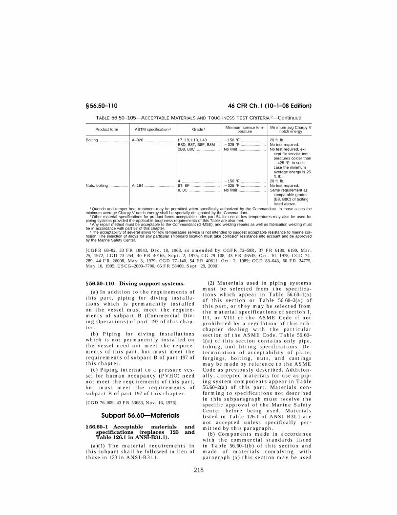
218
46 CFR Ch. I (10–1–08 Edition) § 56.50–110
TABLE 56.50–105—ACCEPTABLE MATERIALS AND TOUGHNESS TEST CRITERIA 2—Continued
Product form ASTM specification 3 Grade 4 Minimum service tem-perature
Minimum avg Charpy V notch energy
Bolting .......................... A–320 ........................... L7, L9, L10, L43 .......... ¥150 °F ....................... 20 ft. lb. B8D, B8T, B8F, B8M ... ¥325 °F ....................... No test required. 2B8, B8C ..................... No limit ......................... No test required, ex-
cept for service tem-peratures colder than ¥425 °F. In such case the minimum average energy is 25 ft. lb.
4 ................................... ¥150 °F ....................... 20 ft. lb. Nuts, bolting ................. A–194 ........................... 8T, 8F .......................... ¥325 °F ....................... No test required.
8, 8C ............................ No limit ......................... Same requirement as comparable grades (B8, B8C) of bolting listed above.
1 Quench and temper heat treatment may be permitted when specifically authorized by the Commandant. In those cases the minimum average Charpy V-notch energy shall be specially designated by the Commandant.
2 Other material specifications for product forms acceptable under part 54 for use at low temperatures may also be used for piping systems provided the applicable toughness requirements of this Table are also met.
3 Any repair method must be acceptable to the Commandant (G-MSE), and welding repairs as well as fabrication welding must be in accordance with part 57 of this chapter.
4 The acceptability of several alloys for low temperature service is not intended to suggest acceptable resistance to marine cor-rosion. The selection of alloys for any particular shipboard location must take corrosion resistance into account and be approved by the Marine Safety Center.
[CGFR 68–82, 33 FR 18843, Dec. 18, 1968, as amended by CGFR 72–59R, 37 FR 6189, 6190, Mar. 25, 1972; CGD 73–254, 40 FR 40165, Sept. 2, 1975; CG 79–108, 43 FR 46545, Oct. 10, 1978; CGD 74– 289, 44 FR 26008, May 3, 1979; CGD 77–140, 54 FR 40611, Oct. 2, 1989; CGD 83–043, 60 FR 24775, May 10, 1995; USCG–2000–7790, 65 FR 58460, Sept. 29, 2000]
§ 56.50–110 Diving support systems.
(a) In addition to the requirements of this part, piping for diving installa-tions which is permanently installed on the vessel must meet the require-ments of subpart B (Commercial Div-ing Operations) of part 197 of this chap-ter.
(b) Piping for diving installations which is not permanently installed on the vessel need not meet the require-ments of this part, but must meet the requirements of subpart B of part 197 of this chapter.
(c) Piping internal to a pressure ves-sel for human occupancy (PVHO) need not meet the requirements of this part, but must meet the requirements of subpart B of part 197 of this chapter.
[CGD 76–009, 43 FR 53683, Nov. 16, 1978]
Subpart 56.60—Materials
§ 56.60–1 Acceptable materials and specifications (replaces 123 and Table 126.1 in ANSI-B31.1).
(a)(1) The material requirements in this subpart shall be followed in lieu of those in 123 in ANSI-B31.1.
(2) Materials used in piping systems must be selected from the specifica-tions which appear in Table 56.60–1(a) of this section or Table 56.60–2(a) of this part, or they may be selected from the material specifications of section I, III, or VIII of the ASME Code if not prohibited by a regulation of this sub-chapter dealing with the particular section of the ASME Code. Table 56.60– 1(a) of this section contains only pipe, tubing, and fitting specifications. De-termination of acceptability of plate, forgings, bolting, nuts, and castings may be made by reference to the ASME Code as previously described. Addition-ally, accepted materials for use as pip-ing system components appear in Table 56.60–2(a) of this part. Materials con-forming to specifications not described in this subparagraph must receive the specific approval of the Marine Safety Center before being used. Materials listed in Table 126.1 of ANSI B31.1 are not accepted unless specifically per-mitted by this paragraph.
(b) Components made in accordance with the commercial standards listed in Table 56.60–1(b) of this section and made of materials complying with paragraph (a) this section may be used
VerDate Aug<31>2005 13:25 Nov 13, 2008 Jkt 214189 PO 00000 Frm 00228 Fmt 8010 Sfmt 8010 Y:\SGML\214189.XXX 214189eben
thal
l on
PR
OD
1PC
60 w
ith C
FR

219
Coast Guard, Dept. of Homeland Security § 56.60–1
in piping systems within the limita-tions of the standards and within any
further limitations specified in this subchapter.
TABLE 56.60–1(A)—ADOPTED SPECIFICATIONS AND STANDARDS NOTE: Table 56.60–1(A) replaces Table 126.1 in ANSI B31.1 and sets forth specifications of pipes, tubing, and fittings intended
for use in piping-systems. The first column lists acceptable standards from ASTM; the second lists those from ANSI. The Coast Guard will consider use of alternative pipes, tubing, and fittings when it receives certification of their mechanical prop-erties. Without this certification it will restrict use of such alternatives to piping-systems inside heat exchangers that ensure containment of the material inside pressure shells.
Pipe, seamless: A106 Carbon steel ............................................................ ANSI-B31.1 .................................................A335 Ferritic alloys ........................................................... ANSI-B31.1 .................................................A376 Austenitic alloys ...................................................... ANSI-B31.1 ................................................. (1).
Pipe, seamless and welded: A53 Types S, F, and E steel pipe .................................... ANSI-B31.1 ................................................. (2,3,4). A312 Austenitic steel (welded with no filler metal) .......... ANSI-B31.1 ................................................. (1,4). A333 Low temperature steel pipe .................................... Sec. VIII, ASME Code ................................ (5).
Pipe, welded: A134 Fusion welded steel plate pipe ............................... See footnote 7 ............................................. (7). A135 ERW pipe ................................................................ ANSI-B31.1 ................................................. (3). A139 Grade B only, fusion welded steel pipe .................. ANSI-B31.1 ................................................. (8). A358 Electric fusion welded pipe, high temperature,
austenitic.ANSI-B31.1 ................................................. (1,4,9).
Pipe, forged and bored: A369 Ferritic alloy ............................................................. ANSI-B31.1 .................................................
Pipe, centrifugally cast: ............................................................ (None applicable) ........................................ (1,9) Tube, seamless:
A179 Carbon steel heat exchanger and condenser tubes.
UCS23, Sec. VIII, ASME Code ................... (11).
A192 Carbon steel boiler tubes ........................................ PG23.1, Sec. I, ASME Code ...................... (10). A210 Medium carbon boiler tubes ................................... PG23.1, Sec. I, ASME Code ......................A213 Ferritic and austenitic boiler tubes .......................... PG23.1, Sec. I, ASME Code ...................... (1).
Tube, seamless and welded: A268 Seamless and ERW ferritic stainless tubing .......... PG23.1, Sec. I, ASME Code ...................... (4). A334 Seamless and welded (no added filler metal) car-
bon and low alloy tubing for low temperature.UCS23, Sec. VIII, ASME Code ................... (4,5).
Tube, welded: A178 (Grades A and C only) ERW boiler tubes .............. PG23.1, Sec. I, ASME Code ...................... (10 Grade A) (4). A214 ERW heat exchanger and condenser tubes .......... UCS27, Sec. VIII, ASME Code ...................A226 ERW boiler and superheater tubes ........................ PG23.1, Sec. I, ASME Code ...................... (4,10). A249 Welded austenitic boiler and heat exchanger
tubes (no added filler metal).PG23.1, Sec. I, ASME Code ...................... (1,4).
Wrought fittings (factory made): A234 Carbon and ferritic alloys ........................................ Conforms to applicable American National
Standards (ANSI-B16.9 and ANSI- B16.11).
(12).
A403 Austenitic alloys ...................................................... ......do .......................................................... (12). A420 Low temperature carbon and steel alloy ................ ......do .......................................................... (12).
Castings,13 iron: A47 Malleable iron ............................................................ Conform to applicable American National
Standards or refer to UCI–23 or UCD– 23, Sec. VIII, ASME Code.
(14).
A126 Gray iron ................................................................. ......do .......................................................... (14). A197 Malleable iron .......................................................... ......do .......................................................... (14). A395 Ductile iron .............................................................. UCD–23, Sec. VIII, ASME Code ................ (14). A536 Ductile iron .............................................................. See footnote 20 ........................................... (20).
NONFERROUS MATERIALS 15
Pipe, seamless: B42 Copper ...................................................................... UNF23, Sec. VIII, ASME Code ................... (16). B43 Red brass .................................................................. ......do ..........................................................B241 Aluminum alloy ........................................................ ......do ..........................................................
Pipe and tube, seamless: B161 Nickel ...................................................................... ......do ..........................................................B165 Nickel-copper .......................................................... ......do ..........................................................B167 Ni-Cr-Fe .................................................................. ......do ..........................................................B315 Copper-silicon ......................................................... ......do ..........................................................
Tube, seamless: B68 Copper ...................................................................... See footnote 17 ........................................... (16,17,18). B75 Copper ...................................................................... UNF23, Sec. VIII, ASME Code ................... (16). B88 Copper ...................................................................... See footnote 17 ........................................... (16,17). B111 Copper and copper alloy ........................................ UNF23, Sec. VIII, ASME Code ...................B210 Aluminum alloy, drawn ............................................ ......do ..........................................................
VerDate Aug<31>2005 13:25 Nov 13, 2008 Jkt 214189 PO 00000 Frm 00229 Fmt 8010 Sfmt 8010 Y:\SGML\214189.XXX 214189eben
thal
l on
PR
OD
1PC
60 w
ith C
FR

220
46 CFR Ch. I (10–1–08 Edition) § 56.60–1
TABLE 56.60–1(A)—ADOPTED SPECIFICATIONS AND STANDARDS—Continued NOTE: Table 56.60–1(A) replaces Table 126.1 in ANSI B31.1 and sets forth specifications of pipes, tubing, and fittings intended
for use in piping-systems. The first column lists acceptable standards from ASTM; the second lists those from ANSI. The Coast Guard will consider use of alternative pipes, tubing, and fittings when it receives certification of their mechanical prop-erties. Without this certification it will restrict use of such alternatives to piping-systems inside heat exchangers that ensure containment of the material inside pressure shells.
B234 Aluminum alloy, drawn ............................................ ......do ..........................................................B280 Copper tube for refrigeration service ...................... See footnote 17 ........................................... (16,17).
Welding fittings: B361 Wrought aluminum welding fittings ......................... Shall meet ANSI Standards ........................
ASTM specification Minimum tensile Longitu-
dinal joint efficiency
P No. Allowable stresses (p.s.i.)
A134: Grade 285A ........................................................ 45,000 0.80 1 11,250×0,8=9,000. Grade 285B ........................................................ 50,000 0.80 1 12,500×0,8=10,000. Grade 285C ....................................................... 55,000 0.80 1 13,750×0,8=11,000.
NOTE: When using 104.1.2 in ANSI-B31.1 to compute wall thickness, the stress shown here shall be applied as though taken from the stress tables. An additional factor of 0.8 may be required by § 56.07–10(c) and (e).
1 For austenitic materials where two sets of stresses appear, use the lower values. 2 Type F (Furnace welded, using open hearth, basic oxygen, or electric furnace only) limited to Class II applications with a
maximum service temperature of 450 °F. Type E (ERW grade) limited to maximum service temperature of 650 °F, or less. 3 Electric resistance welded pipe or tubing of this specification may be used to a maximum design pressure of 350 pounds per
square inch gage. 4 Refer to limitations on use of welded grades given in § 56.60–2(b). 5 Use generally considered for Classes I-L and II-L applications. For Class I-L service only, the seamless grade is permitted.
For other service refer to footnote 4 and to § 56.50–105. 6 Furnace lap or furnace butt grades only. Limited to Class II applications only where the maximum service temperature is 450
°F, or less. 7 Limited to Grades 285A, 285B, and 285C only (straight and spiral seam). Limited to Class II applications only where max-
imum service temperature is 300 °F or less for straight seam, and 200 °F or less for spiral seam. 8 Limited to Class II applications where the maximum service temperature is 300 °F or less for straight seam and 200 °F or
less for spiral seam. 9 For Class I applications only the Class I Grade of the specification may be used. 10 When used in piping systems, a certificate shall be furnished by the manufacturer certifying that the mechanical properties
at room temperature specified in ASTM A520 have been met. Without this certification, use is limited to applications within heat exchangers.
11 When used in piping systems, a certificate shall be furnished by the manufacturer certifying that the mechanical properties for A192 in ASTM A520 have been met. Without this certification, use is limited to applications within heat exchangers.
12 Hydrostatic testing of these fittings is not required but all fittings shall be capable of withstanding without failure, leakage, or impairment of serviceability, a hydrostatic test of 11⁄2 times the designated rating pressure.
13 Other acceptable iron castings are in UCI–23 and UCD–23 of section VIII of the ASME Code. (See also §§ 56.60–10 and 56.60–15.) Acceptable castings of materials other than cast iron may be found in section I or VIII of the ASME Code.
14 Acceptable when complying with American National Standards. Ductile iron is acceptable for temperatures not exceeding 650 °F. For pressure temperature limitations refer to UCD–3 of section VIII of the ASME Code. Other grades of cast iron are ac-ceptable for temperatures not exceeding 450 °F. For pressure temperature limitations refer to UCI–3 of section VIII of the ASME Code.
15 For limitations in use refer to §§ 56.10–5(c) and 56.60–20. 16 Copper pipe must not be used for hot oil systems except for short flexible connections at burners. Copper pipe must be an-
nealed before installation in Class I piping systems. See also §§ 56.10–5(c) and 56.60–20. 17 The stress values shall be taken from UNF23 of section VIII of the ASME Code for B75 annealed and light drawn temper as
appropriate. 18 B68 shall be acceptable if provided with a mill hydrostatic or eddy current test. 19 Centrifugally cast pipe must be specifically approved by the Marine Safety Center. 20 Limited to pipe fittings and valves. See § 56.60–15(d) for additional information.
TABLE 56.60–1(B)—ADOPTED STANDARDS AP-PLICABLE TO PIPING SYSTEMS (REPLACES TABLE 126.1)
ANSI Standards (American National Standards Institute), 11 West 42nd Street, New York, NY 10036.
B1.1 ....... Unified Screw Threads. B1.20.1 .. Pipe Threads, General Purpose. B1.20.3 .. Dryseal Pipe Threads. B2.1 ....... Pipe Threads. B2.2 ....... [Reserved] B16.1 ..... C.I. Flanges and Fittings—Classes 125 and 250
Only. B16.3 ..... M.I. Threaded Fittings—Classes 150 and 300. B16.4 ..... C.I. Threaded Fittings—Classes 125 and 250. B16.5 ..... Steel Pipe Flanges and Flanged Fittings.3 B16.9 ..... Steel Buttwelding Fittings.3 B16.10 ... Dimensions of Ferrous Valves. B16.11 ... Steel S.W. and Threaded Fittings.
TABLE 56.60–1(B)—ADOPTED STANDARDS AP-PLICABLE TO PIPING SYSTEMS (REPLACES TABLE 126.1)—Continued
B16.14 ... Ferrous-Threaded Plugs, Bushings and Lock-nuts.4
B16.15 ... Cast Bronze Threaded Fittings—Classes 125 & 250.4
B16.18 ... Cast Copper Alloy Solder Joints.4 B16.20 ... Ring Joint Gaskets—Steel Flanges. B16.21 ... Non-metallic Gaskets for Flanges. B16.22 ... Wrought Copper and Copper Alloy Solder Joint
Fittings.4 B16.23 ... Cast Copper Alloy Solder-Joint Drainage Fit-
tings.4 B16.24 ... Bronze Pipe Flanges and Flanged Fittings—Class
150 and 300.3 B16.25 ... Butt Welding Ends—Pipe, Valves, Flanges, & Fit-
tings.
VerDate Aug<31>2005 13:25 Nov 13, 2008 Jkt 214189 PO 00000 Frm 00230 Fmt 8010 Sfmt 8010 Y:\SGML\214189.XXX 214189eben
thal
l on
PR
OD
1PC
60 w
ith C
FR

221
Coast Guard, Dept. of Homeland Security § 56.60–2
TABLE 56.60–1(B)—ADOPTED STANDARDS AP-PLICABLE TO PIPING SYSTEMS (REPLACES TABLE 126.1)—Continued
B16.28 ... Wrought Steel Buttwelding Short Radius Elbows and Returns.4
B16.29 ... Wrought Copper and Wrought-Copper Alloy Sol-der Joint Drainage Fittings.4
B16.34 ... Valves—Flanged, Threaded and Welding end.3 B16.42 ... Ductile Iron Pipe Flanges and Fittings.3 B18.2 ..... [Reserved] B18.2.1 .. Square and Hex Bolts and Screws, Inch series. B18.2.2 .. Square and Hex Nuts.
ASTM Standards (American Society for Testing and Mate-rials), 100 Barr Harbor Drive, Conshohocken, PA 19428– 2959.
F682 ...... Wrought Carbon Steel Sleeve-Type Couplings. F1006 .... Entrainment Separators for Use in Marine Piping
Applications.4 F1007 .... Pipe Line Expansion Joints of the Packed Slip
Type for Marine Applications. F1020 .... Line Blind Valves for Marine Applications.4 F1120 .... Circular Metallic Bellows Type Expansion Joints. F1123 .... Non-Metallic Expansion Joints. F1139 .... Steam Traps and Drains. F1172 .... Fuel Oil Meters of the Volumetric Positive Dis-
placement Type. F1173 .... Epoxy Resin Fiberglass Pipe and Fittings to be
Used for Marine Applications. F1199 .... Cast and Welded Pipe Line Strainers. F1200 .... Fabricated (Welded) Pipe Line Strainers. F1201 .... Fluid Conditioner Fittings in Piping Applications
Above 0 °F.
EJMA Standards (Expansion Joint Manufacturers Association, Inc.), 25 North Broadway, Tarrytown, NY 10591
Standards of the Expansion Joint Manufacturers Association, Inc.
FCI Standards (Fluid Controls Institute, Inc.), 31 South Street, Suite 303, Morristown, NJ 07960.
FCI 69–1 Pressure Rating Standard for Steam Traps.4
MSS Standards (Manufacturers’ Standardization Society of the Valve and Fittings Industry), 127 Park Street NE, Vi-enna, VA 22180.
B36.10 ... Wrought-Steel & Iron Pipe. B36.19 ... Stainless Steel Pipe.
MSS Standards (Manufacturers’ Standardization Society of the Valve and Fittings Industry), 1815 North Fort Myer Drive, Arlington, Va. 22209.
SP–6 ...... Finishes-On Flanges, Valves & Fittings. SP–9 ...... Spot-Facing. SP–25 .... Standard Marking System for Valves, Fittings,
Flanges and Unions. SP–37 .... [Reserved] SP–42 .... [Reserved] SP–44 .... Steel Pipe Line Flanges.4 SP–45 .... Bypass and Drain Connection. SP–51 .... Class 150LW Corrosion Resistant Cast Flanges
and Flanged Fittings.4 SP–53 .... Magnetic Particle Inspection—Steel Castings. SP–55 .... Visual Inspection—Steel Castings. SP–58 .... Pipe Hangers & Supports. SP–61 .... Hydrostatic Testing Steel Valves. SP–66 .... [Reserved] SP–67 .... Butterfly Valves.2,4 SP–69 .... Pipe Hangers and Supports—Selection and Ap-
plication.
TABLE 56.60–1(B)—ADOPTED STANDARDS AP-PLICABLE TO PIPING SYSTEMS (REPLACES TABLE 126.1)—Continued
SP–72 .... Ball Valves with Flanged or Butt-Welding Ends for General Service.4
SP–73 .... Silver Brazing Joints for Wrought and Cast Solder Joint Fittings.
SP–83 .... Carbon Steel Pipe Unions Socket-Welding and Threaded.
1 [Reserved] 2 In addition, for bronze valves, adequacy of body shell
thickness shall be satisfactory to the Marine Safety Center. Refer to § 56.60–10 of this part for cast iron valves.
3 Mill or manufacturer’s certification is not required, except where a needed portion of the required marking is deleted due to size or is absent due to age of existing stocks.
4 Because this standard offers the option of several mate-rials, some of which are not generally acceptable to the Coast Guard, compliance with the standard does not necessarily in-dicate compliance with these regulations. The marking on the component or the manufacturer or mill certificate must indi-cate the material specification and/or grade as necessary to fully identify the materials used. The material used must com-ply with the requirements in this subchapter relating to the particular application.
[CGFR 68–82, 33 FR 18843, Dec. 18, 1968, as amended by CGFR 69–127, 35 FR 9978, June 17, 1970; CGFR 72–59R, 37 FR 6190, Mar. 25, 1972; CGD 72–206R, 38 FR 17229, June 29, 1973; CGD 73–248, 39 FR 30839, Aug. 26, 1974; CGD 73–254, 40 FR 40165, Sept. 2, 1975; CGD 77–140, 54 FR 40611, Oct. 2, 1989; 55 FR 39968, 39969, Oct. 1, 1990; CGD 95–027, 61 FR 26001, May 23, 1996; USCG–1999–6216, 64 FR 53224, Oct. 1, 1999; USCG–1999–5151, 64 FR 67180, Dec. 1, 1999]
§ 56.60–2 Limitations on materials. Welded pipe and tubing. The following
restrictions apply to the use of welded pipe and tubing specifications when utilized in piping systems, and not when utilized in heat exchanger, boiler, pressure vessel, or similar components:
(a) Longitudinal joint. Wherever pos-sible, the longitudinal joint of a welded pipe shall not be pierced with holes for branch connections or other purposes.
(b) Class II. Use unlimited except as restricted by maximum temperature or pressure specified in Table 56.60–1(a) or by the requirements contained in § 56.10–5(b) of this chapter.
(c) Class I. (1) For those specifica-tions in which a filler metal is used, the following applies to the material as furnished prior to any fabrication:
(i) For use in service above 800 °F. full welding procedure qualifications by the Coast Guard are required. See part 57 of this subchapter.
(ii) Ultrasonic examination as re-quired by item S–6 in ASTM A–376 shall be certified as having been met in all applications except where 100 percent
VerDate Aug<31>2005 13:25 Nov 13, 2008 Jkt 214189 PO 00000 Frm 00231 Fmt 8010 Sfmt 8010 Y:\SGML\214189.XXX 214189eben
thal
l on
PR
OD
1PC
60 w
ith C
FR

222
46 CFR Ch. I (10–1–08 Edition) § 56.60–3
radiography is a requirement of the particular material specification.
(2) For those specifications in which no filler material is used in the welding process, the ultrasonic examination as required by item S–6 in ASTM A–376 shall be certified as having been met for service above 800 °F.
TABLE 56.60–2(A)—ADOPTED SPECIFICATIONS NOT LISTED IN THE ASME CODE
ASTM specifications Source of allowable stress Notes
FERROUS MATERIALS 1
Bar stock: A276 (Grades See footnote 4. ........ (4).
304–A, 304L–A, 310–A, 316–A, 316L–A, 321–A, 347–A, and 348–A).
A575 and A576 (Grades 1010–1030) See footnote 2 ......... (2,3).
NONFERROUS MATERIALS
Bar stock: B16 (soft and half hard
tempers).See footnote 5 ......... (5,7).
B21 (alloys A, B, and C).
See footnote 8 ......... (8).
B124: Alloy 377 .................. See footnotes 5 and
9.(5,9).
Alloy 464 .................. See footnote 8 ......... (8,10). Alloy 655 .................. See footnote 11 ....... (11). Alloy 642 .................. See footnote 12 ....... (7,12). Alloy 630 .................. See footnote 13 ....... (7,13). Alloy 485 .................. See footnote 8 ......... (8,10).
Forgings: B283 (forging brass) ... See footnotes 5 and
9.(5 9).
Castings: B26 .............................. See footnotes 5, 14,
and 15.(5,14,15).
B85 .............................. See footnotes 5, 14, and 15.
(5,14,15).
1 For limitations in use refer to § 56.60–5. 2 Allowable stresses shall be the same as those listed in
UCS23 of section VIII of the ASME Code for SA–675 material of equivalent tensile strength.
3 Physical testing shall be performed as for material manu-factured to ASME Specification SA–675, except that the bend test shall not be required.
4 Allowable stresses shall be the same as those listed in UCS23 of section VIII of the ASME Code for the cor-responding SA–182 material.
5 Limited to air and hydraulic service with a maximum de-sign temperature of 150 °F. The material must not be used for salt water service or other fluids that may cause dezincification or stress corrosion cracking.
6 [Reserved] 7 An ammonia vapor test, in accordance with ASTM B 858M
(incorporated by reference, see § 56.01–2), shall be per-formed on a representative model of each finished product design.
8 Allowable stresses shall be the same as those listed in UNF23 of section VIII of the ASME Code for SB–171, naval brass.
9 An ammonia vapor test, in accordance with ASTM B 858 (incorporated by reference, see § 56.01–2), shall be per-formed on a representative model for each finished product design. Tension tests shall be performed to determine tensile strength, yield strength, and elongation. Minimum values shall be those listed in table 3 of ASTM B283.
10 Physical testing, including mercurous nitrate test, shall be performed as for material manufactured to ASTM B21.
11 Physical testing shall be performed as for material manu-factured to ASTM B96. Allowable stresses shall be the same as those listed in UNF23 of section VIII of the ASME Code for SB–96 and shall be limited to a maximum allowable tempera-ture of 212 °F.
12 Physical testing shall be performed as for material manu-factured to ASTM B171, alloy D. Allowable stresses shall be the same as those listed in UNF23 of section VIII of the ASME Code for SB–171, aluminum bronze D.
13 Physical testing shall be performed as for material manu-factured to ASTM B171, alloy E. Allowable stresses shall be the same as those listed in UNF23 of section VIII of the ASME Code for SB–171, aluminum bronze, alloy E.
14 Tension tests shall be performed to determine tensile strength, yield strength, and elongation. Minimum values shall be those listed in table X–2 of ASTM B85.
15 Those alloys with a maximum copper content of 0.6 per-cent or less shall be acceptable under this specification. Cast aluminum shall not be welded or brazed.
Note: This Table 56.60–2(a) is a listing of adopted bar stock and nonferrous forging and casting specifications not listed in the ASME Code. Particular attention should be given to the supplementary testing requirements and service limitations contained in the footnotes.
[CGFR 68–82, 33 FR 18843, Dec. 18, 1968, as amended by CGFR 69–127, 35 FR 9978, June 17, 1970; CGD 72–104R, 37 FR 14233, July 18, 1972; CGD 73–248, 39 FR 30839, Aug. 26, 1974; CGD 73–254, 40 FR 40165, Sept. 2, 1975; CGD 77–140, 54 FR 40612, Oct. 2, 1989; CGD 95–012, 60 FR 48050, Sept. 18, 1995; CGD 95–027, 61 FR 26001, May 23, 1996; CGD 95–028, 62 FR 51201, Sept. 30, 1997; USCG–1998–4442, 63 FR 52190, Sept. 30, 1998; USCG–1999–5151, 64 FR 67180, Dec. 1, 1999]
§ 56.60–3 Ferrous materials. (a) Ferrous pipe used for salt water
service must be protected against cor-rosion by hotdip galvanizing or by the use of extra heavy schedule material.
(b) (Reproduces 123.2.3(c)). Carbon or alloy steel having a carbon content of more than 0.35 percent may not be used in welded construction or be shaped by oxygen cutting process or other ther-mal cutting process.
[CGD 73–254, 40 FR 40165, Sept. 2, 1975]
§ 56.60–5 Steel (High temperature ap-plications).
(a) (Reproduces 123.2.3(a).) Upon pro-longed exposure to temperatures above 775 °F., the carbide phase of plain car-bon steel, plain nickel alloy steel, car-bon-manganese alloy steel, manganese- vanadium alloy steel, and carbon-sil-icon steel may be converted to graph-ite.
(b) (Reproduces 123.2.3(b).) Upon pro-longed exposure to temperatures above 875 °F., the carbide phase of alloy steels, such as carbon-molybdenum, manganese-molybdenum-vanadium, manganese-chromium-vanadium and
VerDate Aug<31>2005 13:25 Nov 13, 2008 Jkt 214189 PO 00000 Frm 00232 Fmt 8010 Sfmt 8010 Y:\SGML\214189.XXX 214189eben
thal
l on
PR
OD
1PC
60 w
ith C
FR

223
Coast Guard, Dept. of Homeland Security § 56.60–20
1 For definitions of flammable or combus-tible fluids, see §§ 30.10–15 and 30.10–22 of sub-chapter D (Tank Vessels) of this chapter.
chromium-vanadium, may be con-verted to graphite.
(c) [Reserved] (d) The design temperature of a pip-
ing system employing one or more of the materials listed in paragraphs (a), (b), and (c) of this section shall not ex-ceed the lowest graphitization tem-perature specified for materials used.
[CGFR 68–82, 33 FR 18843, Dec. 18, 1968, as amended by CGFR 69–127, 35 FR 9978, June 17, 1970; CGD 72–104R, 37 FR 14233, July 18, 1972; CGD 73–248, 39 FR 30839, Aug. 26, 1974; CGD 73–254, 40 FR 40165, Sept. 2, 1975]
§ 56.60–10 Cast iron and malleable iron.
(a) The low ductility of cast iron and malleable iron should be recognized and the use of these metals where shock loading may occur should be avoided. Cast iron and malleable iron components shall not be used at tem-peratures above 450 °F. Cast iron and malleable iron fittings conforming to the specifications of Table 56.60–1(a) of this part may be used at pressures not exceeding the limits of the applicable standards of Table 56.60–1(b) of this part at temperatures not exceeding 450 °F. Valves of either of these materials may be used if they conform to the standards for class 125 and class 250 flanges and flanged fittings in ANSI B16.1 and if their service does not ex-ceed the rating as marked on the valve.
(b) Cast iron and malleable iron shall not be used for valves or fittings in lines carrying flammable or combus-tible fluids 1 which are directly con-nected to, or in the proximity of, equipment or other lines having open flame, or any parts operating at tem-peratures above 500 °F. Cast iron shall not be used for hull fittings, or in sys-tems conducting lethal products.
(c) Malleable iron and cast iron valves and fittings, designed and marked for Class 300 refrigeration serv-ice, may be used for such service pro-vided the pressure limitation of 300 pounds per square inch is not exceeded. Malleable iron flanges of this class
may also be used in sizes 4 inches and smaller (oval and square design).
[CGFR 68–82, 33 FR 18843, Dec. 18, 1968, as amended by CGFR 69–127, 35 FR 9978, June 17, 1970; CGD 73–254, 40 FR 40165, Sept. 2, 1975; CGD 77–140, 54 FR 40612, Oct. 2, 1989; CGD 95– 027, 61 FR 26001, May 23, 1996]
§ 56.60–15 Ductile iron. (a) Ductile cast iron components
made of material conforming to ASTM A 395 (incorporated by reference, see § 56.01–2) may be used within the serv-ice restrictions and pressure-tempera-ture limitations of UCD–3 of section VIII of the ASME Code.
(b) Ductile iron castings conforming to ASTM A 395 (incorporated by ref-erence, see § 56.01–2) may be used in hy-draulic systems at pressures in excess of 7500 kilopascals (1000 pounds per square inch) gage, provided the fol-lowing:
(1) The castings receive a ferritizing anneal when the as-cast thickness does not exceed one inch;
(2) Large castings for components, such as hydraulic cylinders, are exam-ined as specified for a casting quality factor of 90 percent in accordance with UG–24 of section VIII of the ASME Code; and
(3) The castings are not welded, brazed, plugged, or otherwise repaired.
(c) After machining, ductile iron castings must be hydrostatically tested to twice their maximum allowable working pressure and must show no leaks.
(d) Ductile iron castings exhibiting less than 12 percent elongation in 50 millimeters (2 inches) when subjected to a tensile test must meet the require-ments for cast iron in this part.
[CGD 77–140, 54 FR 40612, Oct. 2, 1989, as amended by CGD 95–027, 61 FR 26001, May 23, 1996; USCG–2000–7790, 65 FR 58460, Sept. 29, 2000]
§ 56.60–20 Nonferrous materials. Nonferrous materials listed in this
subpart may be used in piping systems under the following conditions (see also § 56.10–5(c)):
(a) The low melting points of many nonferrous metals and alloys, such as aluminum and aluminum alloys, must be recognized. These types of heat sen-sitive materials must not be used to
VerDate Aug<31>2005 13:25 Nov 13, 2008 Jkt 214189 PO 00000 Frm 00233 Fmt 8010 Sfmt 8010 Y:\SGML\214189.XXX 214189eben
thal
l on
PR
OD
1PC
60 w
ith C
FR

224
46 CFR Ch. I (10–1–08 Edition) § 56.60–25
conduct flammable, combustible, or dangerous fluids, or for vital systems unless approved by the Marine Safety Center.
NOTE: For definitions of flammable or com-bustible fluids, see §§ 30.10–15 and 30.10–22 or parts 151–154 of this chapter. Dangerous fluids are those covered by regulations in part 98 of this chapter.
(b) The possibility of galvanic corro-sion due to the relative solution poten-tials of copper and aluminum and their alloys should be considered when used in conjunction with each other or with steel or with other metals and their al-loys when an electrolyte is present.
(c) A suitable thread compound must be used in making up threaded joints in aluminum pipe to prevent seizing which might cause leakage and perhaps prevent disassembly. Pipe in the an-nealed temper should not be threaded.
(d) The corrosion resistance of copper bearing aluminum alloys in a marine atmosphere is poor and alloys with copper contents exceeding 0.6 percent should not be used. Refer to Table 56.60–2(a) of this part for further guid-ance.
[CGFR 68–82, 33 FR 18843, Dec. 18, 1968, as amended by CGD 77–140, 54 FR 40612, Oct. 2, 1989; CGD 95–027, 61 FR 26001, May 23, 1996]
§ 56.60–25 Nonmetallic materials. (a) Plastic pipe installations shall be
in accordance with the International Maritime Organization (IMO) resolu-tion A.753(18), Guidelines for the Appli-cation of Plastic Pipes on Ships and the following supplemental require-ments:
(1) Materials used in the fabrication of plastic pipe shall comply with the appropriate standards listed in § 56.01–2 of this chapter.
(2) Plastic pipe is not permitted in a concealed space in an accommodation or service area, such as behind ceilings or linings or between double bulkheads, unless—
(i) Each trunk or duct containing such piping is completely surrounded by ‘‘A’’ class divisions; or
(ii) An approved smoke-detection system is fitted in the concealed space and each penetration of a bulkhead or deck and each installation of a draft stop is made in accordance with IMO
resolution A.753(18) to maintain the in-tegrity of fire divisions.
(3) Plastic pipe used outboard of the required metallic shell valve in any piping system penetrating the vessel’s shell (see § 56.50–95(f)) shall have the same fire endurance as the metallic shell valve. Where the shell valve and the plastic pipe are in the same un-manned space, the valve shall be oper-able from above the freeboard deck.
(4) Pipe that is to be used for potable water shall bear the seal of approval or NSF mark of the National Sanitation Foundation Testing Laboratory, Incor-porated, School of Public Health, Uni-versity of Michigan, Ann Arbor, MI 48103.
(b) Nonmetallic flexible hose. (1) Non-metallic flexible hose must be in ac-cordance with SAE J–1942 and may be installed only in vital and nonvital fresh and salt water systems, nonvital pneumatic systems, lube oil and fuel systems, and fluid power systems.
(2) Nonmetallic flexible hose may be used in vital fresh and salt water sys-tems at a maximum service pressure of 150 psi. Nonmetallic flexible hose may be used in lengths not exceeding 30 inches where flexibility is required sub-ject to the limitations of paragraphs (a) (1) through (4) of this section. Non-metallic flexible hose may be used for plastic pipe in duplicate installations in accordance with paragraph (a) of this section.
(3) Nonmetallic flexible hose may be used for plastic pipe in nonvital fresh and salt water systems and nonvital pneumatic systems subject to the limi-tations of paragraphs (a) (1) through (4) of this section. Unreinforced hoses are limited to a maximum service pressure of 50 psi, reinforced hoses are limited to a maximum service pressure of 150 psi.
(4) Nonmetallic flexible hose may be used in lube oil, fuel oil and fluid power systems only where flexibility is re-quired and in lengths not exceeding 30 inches.
(5) Nonmetallic flexible hose must be complete with factory-assembled end fittings requiring no further adjust-ment of the fittings on the hose, except that field attachable type fittings may be used. Hose end fittings must comply
VerDate Aug<31>2005 13:25 Nov 13, 2008 Jkt 214189 PO 00000 Frm 00234 Fmt 8010 Sfmt 8010 Y:\SGML\214189.XXX 214189eben
thal
l on
PR
OD
1PC
60 w
ith C
FR

225
Coast Guard, Dept. of Homeland Security § 56.70–10
with SAE J–1475. Field attachable fit-tings must be installed following the manufacturer’s recommended practice. If special equipment is required, such as crimping machines, it must be of the type and design specified by the manu-facturer. A hydrostatic test of each hose assembly must be conducted in accordance with § 56.97–5 of this part.
(c) Plastic valves, fittings, and flanges may be used in systems em-ploying plastic pipe. Such valves, fit-tings, and flanges shall be designed, fabricated, tested, and installed so as to satisfy the intent of the require-ments for plastic pipe contained in this section.
(d) If it is desired to use nonmetallic materials other than those specified in this section, a request furnishing the chemical and physical properties of the material shall be submitted to the Commandant for consideration.
[CGFR 68–82, 33 FR 18843, Dec. 18, 1968, as amended by CGFR 69–127, 35 FR 9979, June 17, 1970; CGD 72–104R, 37 FR 14234, July 18, 1972; CGD 73–254, 40 FR 40165, Sept. 2, 1975; CGD 77– 140, 54 FR 40613, Oct. 2, 1989; CGD 88–032, 56 FR 35822, July 29, 1991; CGD 83–043, 60 FR 24775, May 10, 1995; CGD 95–072, 60 FR 50462, Sept. 29, 1995; CGD 96–041, 61 FR 50728, Sept. 27, 1996; CGD 95–028, 62 FR 51201, Sept. 30, 1997; USCG–2002–13058, 67 FR 61278, Sept. 30, 2002]
Subpart 56.65—Fabrication, Assembly and Erection
§ 56.65–1 General (replaces 127 through 135.4).
(a) The requirements for fabrication, assembly and erection in subparts 56.70 through 56.90 shall apply in lieu of 127 through 135.4 of ANSI-B31.1. Those paragraphs reproduced are so noted.
[CGFR 68–82, 33 FR 18843, Dec. 18, 1968, as amended by CGFR 69–127, 35 FR 9978, June 17, 1970]
Subpart 56.70—Welding
§ 56.70–1 General.
(a) The following generally applies to all types of welding, such as stud weld-ing, casting repair welding and all processes of fabrication welding. Where the detailed requirements are not ap-propriate to a particular process, alter-
natives must be approved by the Ma-rine Safety Center.
[CGD 77–140, 54 FR 40614, Oct. 2, 1989]
§ 56.70–3 Limitations.
Backing rings. Backing strips used at longitudinal welded joints must be re-moved.
[CGD 73–254, 40 FR 40165, Sept. 2, 1975]
§ 56.70–5 Material.
(a) Filler metal. All filler metal, in-cluding consumable insert material, must comply with the requirements of section IX, ASME Boiler and Pressure Vessel Code and § 57.02–5 of this sub-chapter.
(b) Backing rings. When metallic backing rings are used they shall be made from material of weldable qual-ity compatible with the base metal, whether subsequently removed or not. When nonmetallic backing rings are used they shall be of material which does not deleteriously affect either base or weld metal, and shall be re-moved after welding is completed. Backing rings may be of the consumable insert type, removable ce-ramic type, of solid or split band type. A ferrous backing ring which becomes a permanent part of the weld shall not exceed 0.05 percent sulphur. If two abutting surfaces are to be welded to a third member used as a backing ring and one or two of the three members are ferritic and the other member or members are austenitic, the satisfac-tory use of such materials shall be de-termined by procedure qualifications.
[CGFR 68–82, 33 FR 18843, Dec. 18, 1968, as amended by CGD 73–254, 40 FR 40165, Sept. 2, 1975; USCG–2002–13058, 67 FR 61278, Sept. 30, 2002]
§ 56.70–10 Preparation (modifies 127.3).
(a) Butt welds (reproduces 127.3.1)—(1) End preparation. (i) Oxygen or arc cut-ting is acceptable only if the cut is rea-sonably smooth and true, and all slag is cleaned from the flame cut surfaces. Discoloration which may remain on the flame cut surface is not considered to be detrimental oxidation.
(ii) Butt-welding end preparation di-mensions contained in ANSI-B16.25 or any other end preparation which meets
VerDate Aug<31>2005 13:25 Nov 13, 2008 Jkt 214189 PO 00000 Frm 00235 Fmt 8010 Sfmt 8010 Y:\SGML\214189.XXX 214189eben
thal
l on
PR
OD
1PC
60 w
ith C
FR
226
46 CFR Ch. I (10–1–08 Edition) § 56.70–15
the procedure qualification require-ments are acceptable.
(iii) If piping component ends are bored, such boring shall not result in the finished wall thickness after weld-ing being less than the minimum de-sign thickness. Where necessary, weld metal of the appropriate analysis may be deposited on the inside or outside of the piping component to provide suffi-cient material for machining to insure satisfactory fitting of rings.
(iv) If the piping component ends are upset they may be bored to allow for a completely recessed backing ring, pro-vided the remaining net thickness of the finished ends is not less than the minimum design thickness.
(2) Cleaning. Surfaces for welding shall be clean and shall be free from paint, oil, rust, scale, or other material which is detrimental to welding.
(3) Alignment. The inside diameters of piping components to be joined must be aligned as accurately as practicable within existing commercial tolerances on diameters, wall thicknesses, and out of roundness. Alignment must be pre-served during welding. Where ends are to be joined and the internal misalign-ment exceeds 1⁄16-inch, it is preferred that the component with the wall ex-tending internally be internally trimmed (see Fig. 127.3.1) so that ad-joining internal surfaces are approxi-mately flush. However, this trimming must not reduce a piping component wall thickness below the minimum de-sign thickness and the change in the contour may not exceed 30°.
(4) Spacing. The root opening of the joint shall be as given in the procedure specification.
(b) Fillet welds (Modifies 127.3.2). In making fillet welds, the weld metal must be deposited in such a way as to obtain adequate penetration into the base metal at the root of the weld. Pip-ing components which are to be joined utilizing fillet welds must be prepared in accordance with applicable provi-sions and requirements of this section. For typical details, see Figures 127.4.4A and 127.4.4C of ANSI B31.1 and Figure 56.30–10(b) of this part. See § 56.30–5(d)
of this part for additional require-ments.
[CGFR 68–82, 33 FR 18843, Dec. 18, 1968, as amended by CGFR 69–127, 35 FR 9978, June 17, 1970; CGD 73–254, 40 FR 40165, Sept. 2, 1975; CGD 77–140, 54 FR 40614, Oct. 2, 1989]
§ 56.70–15 Procedure. (a) General. (1) Qualification of the
welding procedures to be used, and of the performance of welders and opera-tors, is required, and shall comply with the requirements of part 57 of this sub-chapter.
(2) No welding shall be done if there is direct impingement of rain, snow, sleet, or high wind on the piping com-ponent weldment.
(3) Sections of pipe shall be welded insofar as possible in the fabricating shop. Prior to welding Class I piping or low temperature piping, the fabricator shall request a marine inspector to visit his plant to examine his fabri-cating equipment and to witness the qualification tests required by part 57 of this subchapter. One test specimen shall be prepared for each process and welding position to be employed in the fabrication.
(b) Girth butt welds. (1) (Reproduces 127.4.2(a)). Girth butt welds must be complete penetration welds and may be made with a single vee, double vee, or other suitable type of groove, with or without backing rings or consumable inserts.’’
(2) Girth butt welds in Class I, I-L, and II-L piping systems shall be double welded butt joints or equivalent single welded butt joints for pipe diameters exceeding three-fourth inch nominal pipe size. The use of a single welded butt joint employing a backing ring (note restrictions in paragraph (b)(3)(iv) of this section) on the inside of the pipe is an acceptable equivalent for Class I and Class II-L applications, but not permitted for Class I-L applica-tions. Single welded butt joints em-ploying either an inert gas for first pass backup or a consumable insert ring may be considered the equivalent of a double welded butt joint for all classes of piping and is preferable for Class I-L and II-L systems where dou-ble butt welds cannot be used. Appro-priate welding procedure qualification tests shall be conducted as specified in
VerDate Aug<31>2005 13:25 Nov 13, 2008 Jkt 214189 PO 00000 Frm 00236 Fmt 8010 Sfmt 8010 Y:\SGML\214189.XXX 214189eben
thal
l on
PR
OD
1PC
60 w
ith C
FR

227
Coast Guard, Dept. of Homeland Security § 56.70–15
part 57 of this subchapter. A first pass inert gas backup is intended to mean that the inside of the pipe is purged with inert gas and that the root is welded with the inert gas metal arc (mig) or inert gas tungsten arc (tig) processes. Classes I, I-L, and II-L pip-ing are required to have the inside of the pipe machined for good fit up if the misalignment exceeds that specified in § 56.70–10(a)(3). In the case of Class II piping the machining of the inside of the pipe may be omitted. For single welded joints, where possible, the in-side of the joint shall be examined vis-ually to assure full penetration. Radio-graphic examination of at least 20 per-cent of single welded joints to check for penetration is required for all Class I and Class I-L systems regardless of size following the requirements of § 56.95–10. Ultrasonic testing may be utilized in lieu of radiographic exam-ination if the procedures are approved.
(3) For Class II piping, the type of joints shall be similar to Class I piping, with the following exceptions:
(i) Single-welded butt joints may be employed without the use of backing rings in all sizes provided that the weld is chipped or ground flush on the root side of the weld.
(ii) For services such as vents, over-flows, and gravity drains, the backing ring may be eliminated and the root of the weld need not be ground.
(iii) Square-groove welds without edge preparation may be employed for butt joints in vents, overflows, and gravity drains where the pipe wall thickness does not exceed three-six-teenth inch.
(iv) The crimped or forged backing ring with continuous projection around the outside of the ring is acceptable only for Class II piping. The projection must be completely fused.
(4) Tack welds which become part of the finished weld, shall be made by a qualified welder. Tack welds made by an unqualified welder shall be removed. Tack welds which are not removed shall be made with an electrode which is the same as or equivalent to the electrode to be used for the first pass. Their stopping and starting ends must be properly prepared by grinding or other suitable means so that they may be satisfactorily incorporated into the
final weld. Tack welds which have cracked shall be removed.
(5) (Reproduces 127.2(c)). When com-ponents of different outside diameters are welded together, the weld joint must be filled to the outside surface of the component having the larger di-ameter. There must be a gradual tran-sition, not exceeding a slope of 1:3, in the weld between the two surfaces. To avoid unnecessary weld deposit, the outside surface of the component hav-ing the larger diameter must be ta-pered at an angle not to exceed thirty degrees with the axis of the pipe. (See Fig. 127.4.2.)
(6) (Modifies 127.4.2(d)). As-welded sur-faces are permitted, however, the sur-face of welds must be sufficiently free from coarse ripple, grooves, overlaps, abrupt ridges and valleys to meet the following:
(i) The surface condition of the fin-ished welds must be suitable for the proper interpretation of radiographic and other nondestructive examinations when nondestructive examinations are required by § 56.95–10. In those cases where there is a question regarding the surface condition on the interpretation of a radiographic film, the film must be compared to the actual weld surface for interpretation and determination of ac-ceptability.
(ii) Reinforcements are permitted in accordance with Table 56.70–15.
(iii) Undercuts must not exceed 1⁄32- inch and must not encroach on the minimum required section thickness.
(iv) If the surface of the weld requires grinding to meet the above criteria, care must be taken to avoid reducing the weld or base material below the minimum required thickness.
(7) The type and extent of examina-tion required for girth butt welds is specified in § 56.95–10.
(8) Sections of welds that are shown by radiography or other examination to have any of the following type of im-perfections shall be judged unaccept-able and shall be repaired as provided in paragraph (f) of this section:
(i) Any type of crack or zone of in-complete fusion or penetration.
(ii) Any slag inclusion or porosity greater in extent than those specified as acceptable set forth in PW–51 of sec-tion I of the ASME Code.
VerDate Aug<31>2005 13:25 Nov 13, 2008 Jkt 214189 PO 00000 Frm 00237 Fmt 8010 Sfmt 8010 Y:\SGML\214189.XXX 214189eben
thal
l on
PR
OD
1PC
60 w
ith C
FR

228
46 CFR Ch. I (10–1–08 Edition) § 56.70–15
(iii) Undercuts in the external sur-faces of butt welds which are more than 1⁄32-inch deep.
(iv) Concavity on the root side of full penetration girth butt welds where the resulting weld thickness is less than the minimum pipe wall thickness re-quired by this subchapter. Weld rein-forcement up to a maximum of 1⁄32-inch thickness may be considered as pipe wall thickness in such cases.
(c) Longitudinal butt welds. Longitu-dinal butt welds in piping components not made in accordance with the stand-ards and specifications listed in 56.60–1 (a) and (b) must meet the requirements of paragraph 104.7 of ANSI-B31.1 and may be examined nondestructively by an acceptable method. Imperfections shall not exceed the limits established for girth butt welds except that no un-dercutting shall be permitted in longi-tudinal butt welds. See also § 56.60–2(b).
(d) Fillet welds. (1) Fillet welds may vary from convex to concave. The size of a fillet weld is determined as shown in Figure 127.4.4A in ANSI B31.1. Fillet weld details for socket-welding compo-nents must meet § 56.30–5(c) of this part. Fillet weld details for flanges must meet § 56.30–10(c) of this part. Fil-let weld details for flanges must meet § 56.30–10 of this part.
(2) The limitations on cracks and un-dercutting set forth in paragraph (b)(8) of this section for girth welds are also applicable to fillet welds.
(3) Class I piping not exceeding 3 inches nominal pipe size and not sub-ject to full radiography by § 56.95–10 of this part may be joined by sleeves fitted over pipe ends or by socket type joints. Where full radiography is re-quired, only butt type joints may be used. The inside diameter of the sleeve must not exceed the outside diameter of the pipe or tube by more than 0.080 inch. Fit between socket and pipe must conform to applicable standards for socket weld fittings. Depth of insertion of pipe or tube within the socket or sleeve must not be less than three- eighths inch. The fillet weld must be deposited in a minimum of two passes, unless specifically approved otherwise in a special procedure qualification. Requirements for joints employing socket weld and slip-on flanges are in § 56.30–10 of this part.
(4) Sleeve and socket type joints may be used in Class II piping systems with-out restriction as to size of pipe or tub-ing joined. Applicable standards must be followed on fit. The fillet welds must be deposited in a minimum of two passes, unless specifically approved otherwise in a special procedure quali-fication. Requirements for joints em-ploying socket weld and slip-on flanges are in § 56.30–10 of this part.
(e) Seal welds (reproduces 127.4.5). (1) Where seal welding of threaded joints is performed, threads shall be entirely covered by the seal weld. Seal welding shall be done by qualified welders.
(2) The limitation on cracks and un-dercutting set forth in § 56.70–15(b)(8) for girth welds are also applicable to seal welds.
(f) Weld defect repairs (reproduces 127.4.11). (1) All defects in welds requir-ing repair must be removed by a flame or arc-gouging, grinding, chipping, or machining. Repair welds must be made in accordance with the same proce-dures used for original welds, or by an-other welding process if it is a part of a qualified procedure, recognizing that the cavity to be repaired may differ in contour and dimensions from the origi-nal joint. The types, extent, and meth-od of examination and limits of imper-fections of repair welds shall be the same as for the original weld.
(2) Preheating may be required for flame-gouging or arc-gouging certain alloy materials of the air hardening type in order to prevent surface check-ing or cracking adjacent to the flame or arc-gouged surface.
(g) Welded branch connections (repro-duces 127.4.8). (1) Figure 127.4.8A, Figure 127.4.8B, and Figure 127.4.8C of ANSI- B31.1 show typical details of branch connections with and without added re-inforcement. However, no attempt has been made to show all acceptable types of construction and the fact that a cer-tain type of construction is illustrated does not indicate that it is rec-ommended over other types not illus-trated. See also Figure 56.70–15(g) for additional pipe connections.
(2) Figure 127.4.8D of ANSI-B31.1 shows basic types of weld attachments used in the fabrication of branch con-nections. The location and minimum size of these attachment welds shall
VerDate Aug<31>2005 13:25 Nov 13, 2008 Jkt 214189 PO 00000 Frm 00238 Fmt 8010 Sfmt 8010 Y:\SGML\214189.XXX 214189eben
thal
l on
PR
OD
1PC
60 w
ith C
FR

229
Coast Guard, Dept. of Homeland Security § 56.70–15
conform to the requirements of this paragraph. Weld sizes shall be cal-culated in accordance with 104.3.1 of ANSI-B31.1, but shall not be less than
the sizes shown in Figure 127.4.8D and F of ANSI-B31.1.
(3) The notations and symbols used in this paragraph and in Figure 127.4.8D and F of ANSI-B31.1 are as follows:
FIGURE 56.70–15(G)—ACCEPTABLE TYPES OF WELDED PIPE CONNECTIONS
tn=nominal thickness of branch wall less cor-rosion allowance, inches.
tc=the smaller of 1⁄4 inch or 0.7tn. te=nominal thickness of reinforcing element
(ring or saddle), inches (te=0 if there is no added reinforcement).
tmin=the smaller of tn or te. tw=dimension of partial penetration weld,
inches.
(4) Branch connections (including specially made integrally reinforced branch connection fittings) which abut the outside surface of the run wall, or which are inserted through an opening cut in the run wall, shall have opening and branch contour to provide a good fit and shall be attached by means of full penetration groove welds except as otherwise permitted in paragraph (g)(7) of this section. The full penetration groove welds shall be finished with cover fillet welds having a minimum throat dimension not less than tc. The limitation as to imperfection of these groove welds shall be as set forth in 127.4.2(e) of ANSI-B31.1 for girth welds.
(5) In branch connections having re-inforcement pads or saddles, the rein-forcement shall be attached by welds at the outer edge and at the branch pe-riphery as follows:
(i) If the weld joining the added rein-forcement to the branch is a full pene-tration groove weld, it shall be finished with a cover fillet weld having a min-imum throat dimension not less than tc the weld at the outer edge, joining the added reinforcement to the run, shall be a fillet weld with a minimum throat dimension of 0.5 te.
(ii) If the weld joining the added rein-forcement to the branch is a fillet weld, the throat dimension shall not be less than 0.7 tmin. The weld at the outer edge joining the outer reinforcement to the run shall also be a fillet weld with a minimum throat dimension of 0.5 te.
(6) When rings or saddles are used, a vent hole shall be provided (at the side and not at the crotch) in the ring or saddle to reveal leakage in the weld be-tween branch and main run and to pro-vide venting during welding and heat treating operations. Rings or saddles may be made in more than one piece if the joints between the pieces have strength equivalent to ring or saddle parent metal and if each piece is pro-vided with a vent hole. A good fit shall be provided between reinforcing rings or saddles and the parts to which they are attached.
VerDate Aug<31>2005 13:25 Nov 13, 2008 Jkt 214189 PO 00000 Frm 00239 Fmt 8010 Sfmt 8010 Y:\SGML\214189.XXX 214189 EC
01F
E91
.027
eben
thal
l on
PR
OD
1PC
60 w
ith C
FR

230
46 CFR Ch. I (10–1–08 Edition) § 56.70–20
(7) Branch connections 2 in. NPS and smaller that do not require reinforce-ment may be constructed as shown in Fig. 127.4.8F of ANSI-B31.1. This con-struction is limited to use in Class I and II piping systems at a maximum
design temperature of 750 °F. or a max-imum pressure of 1025 psi.
(h) Heat treatment. Heat treatment for welds shall be in accordance with sub-part 56.85.
TABLE 56.70–15—REINFORCEMENT OF GIRTH AND LONGITUDINAL BUTT WELDS
Thickness (in inches) of base metal
Maximum thickness (in inches) of rein-forcement for design temperature
Below 0 °F or above 750 °F
350° to 750 °F
0 °F and above but less than 350 °F
Up to 1⁄8, inclusive ......................................................................................................... 1⁄16 3⁄32 3⁄16 Over 1⁄8 to 3⁄16, inclusive ............................................................................................... 1⁄16 1⁄8 3⁄16 Over 3⁄16 to 1⁄2, inclusive ............................................................................................... 1⁄16 5⁄32 3⁄16 Over 1⁄2 to 1, inclusive .................................................................................................. 3⁄32 3⁄16 3⁄16 Over 1 to 2, inclusive .................................................................................................... 1⁄8 1⁄4 1⁄4 Over 2 ............................................................................................................................ 5⁄32 (1) (1)
1 The greater of 1⁄4 in. or 1⁄8 times the width of the weld in inches. NOTES: 1. For double welded butt joints, this limitation on reinforcement given above applies separately to both inside and out-
side surfaces of the joint. 2. For single welded butt joints, the reinforcement limits given above apply to the outside surface of the joint only. 3. The thickness of weld reinforcement is based on the thickness of the thinner of the materials being joined. 4. The weld reinforcement thicknesses must be determined for the higher of the abutting surfaces involved. 5. For boiler external piping use the column titled ‘‘Below 0 °F. or above 750 °F.’’ for weld reinforcement thicknesses.
[CGFR 68–82, 33 FR 18843, Dec. 18, 1968, as amended by CGFR 69–127, 35 FR 9978, June 17, 1970; CGD 73–254, 40 FR 40165, Sept. 2, 1975; CGD 77–140, 54 FR 40614, Oct. 2, 1989; 55 FR 39969, Oct. 1, 1990; CGD 95–012, 60 FR 48050, Sept. 18, 1995]
§ 56.70–20 Qualification, general. (a) Qualification of the welding pro-
cedures to be used, and of the perform-ance of welders and welding operators, is required, and shall comply with the requirements of the ASME Boiler and Pressure Vessel Code (section IX) ex-cept as modified by part 57 of this sub-chapter.
(b) Each butt-welded joint of Class I of Class I-L piping shall be marked with the welder’s identification sym-bol. Dies shall not be used to mark the pipe where the pressure exceeds 600 pounds per square inch or the tempera-ture exceeds 750 °F. or in Class I-L sys-tems.
Subpart 56.75—Brazing § 56.75–5 Filler metal.
(a) The filler metal used in brazing must be a nonferrous metal or alloy having a melting point above 1,000 °F. and below that of the metal being joined. The filler metal must meet and flow freely within the desired tempera-ture range and, in conjunction with a suitable flux or controlled atmosphere,
must wet and adhere to the surfaces to be joined. Prior to using a particular brazing material in a piping system, the requirements of § 56.60–20 of this part should be considered.
(b) The brazing material used shall have a shearing strength of at least 10,000 pounds per square inch. The max-imum allowable working pressure for brazing piping shall be determined by this part.
(c) (Reproduces 128.1.2.) Fluxes that are fluid and chemically active at the brazing temperature shall be used when necessary to prevent oxidation of the filler metal and the surfaces to be joined and to promote free flowing of the filler metal.
[CGFR 68–82, 33 FR 18843, Dec. 18, 1968, as amended by CGD 77–140, 54 FR 40615, Oct. 2, 1989]
§ 56.75–10 Joint clearance (reproduces 128.2.2).
(a) The clearance between surfaces to be joined shall be no larger than is nec-essary to insure complete capillary dis-tribution of the filler metal; between
VerDate Aug<31>2005 13:25 Nov 13, 2008 Jkt 214189 PO 00000 Frm 00240 Fmt 8010 Sfmt 8010 Y:\SGML\214189.XXX 214189eben
thal
l on
PR
OD
1PC
60 w
ith C
FR

231
Coast Guard, Dept. of Homeland Security § 56.80–5
0.002–inch minimum and 0.006-inch maximum.
(b) [Reserved]
§ 56.75–15 Heating (reproduces 128.2.3).
(a) The joint shall be brought to braz-ing temperature in as short a time as possible to minimize oxidation.
(b) [Reserved]
§ 56.75–20 Brazing qualification. (a) The qualification of the perform-
ance of brazers and brazing operators, shall be in accordance with the require-ments of part C, section IX of the ASME Code and part 57 of this sub-chapter.
(b) Manufacturers shall perform those tests required by paragraph (a) of this section prior to performing pro-duction brazing.
§ 56.75–25 Detail requirements. (a) Pipe may be fabricated by brazing
when the temperature to which such connections may be subjected does not exceed 425 °F. (For exception refer to § 56.30–30(b)(1).)
(b) (Reproduces 128.2.1.) The surfaces to be brazed shall be clean and free from grease, oxides, paint, scale, and dirt of any kind. Any suitable chemical or mechanical cleaning method may be used to provide a clean wettable sur-face for brazing.
(c) After the parts to be joined have been thoroughly cleaned the edges to be brazed shall be given an even coat-ing of flux prior to heating the joint as a protection against oxidation.
§ 56.75–30 Pipe joining details. (a) Silver brazing. (1) Circumferential
pipe joints may be either of the socket or butt type. When butt joints are em-ployed the edges to be joined shall be cut or machined square and the edges shall be held closely together to insure a satisfactory joint.
(b) Copper-alloy brazing. (1) Copper- alloy brazing may be employed to join pipe, valves, and fittings. Circumferen-tial joints may be either of the butt or socket type. Where butt joints are em-ployed, the included angle shall be not less than 90° where the wall thickness is three-sixteenths of an inch or great-er. The annular clearance of socket
joints shall be held to small clearances which experience indicates is satisfac-tory for the brazing alloy to be em-ployed, method of heating, and mate-rial to be joined. The annular clearance shall be shown on drawings submitted for approval of socket joints.
(2) Copper pipe fabricated with longi-tudinal joints for pressures not exceed-ing that permitted by the regulations in this subchapter may have butt, lapped, or scarfed joints. If of the latter type, the kerf of the material shall be not less than 60°.
(c) Brazing, general. (1) Heat shall be applied evenly and uniformly to all parts of the joint in order to prevent local overheating.
(2) The members to be joined shall be held firmly in place until the brazing alloy has set so as to prevent any strain on the joint until the brazing alloy has thoroughly solidified. The brazing shall be done by placing the flux and brazing material on one side of the joint and applying heat until the brazing material flows entirely through the lap and shows uniformly along the seam on the other side of the joint. Sufficient flux shall be used to cause the brazing material to appear promptly after reaching the brazing temperature.
Subpart 56.80—Bending and Forming
§ 56.80–5 Bending. Pipe may be bent by any hot or cold
method and to any radius which will result in a bend surface free of cracks, as determined by a method of inspec-tion specified in the design, and sub-stantially free of buckles. Such bends shall meet the design requirements of 102.4.5 and 104.2.1 of ANSI-B31.1. This shall not prohibit the use of bends de-signed as creased or corrugated. If doubt exists as to the wall thickness being adequate, Class I piping having diameters exceeding 4 inches shall be nondestructively examined by the use of ultrasonics or other acceptable method. Alternatively, the pipe may be drilled, gaged, and fitted with a screwed plug extending outside the pipe covering. The nondestructive method shall be employed where the design temperature exceeds 750 °F.
VerDate Aug<31>2005 13:25 Nov 13, 2008 Jkt 214189 PO 00000 Frm 00241 Fmt 8010 Sfmt 8010 Y:\SGML\214189.XXX 214189eben
thal
l on
PR
OD
1PC
60 w
ith C
FR

232
46 CFR Ch. I (10–1–08 Edition) § 56.80–10
Prior to the use of nondestructive method of examination by the above procedure, it shall be demonstrated by the user, in the presence of a marine inspector on specimens similar to those to be examined, that consistent re-sults, having an accuracy of plus or minus 3 percent, can be obtained.
[CGFR 68–82, 33 FR 18843, Dec. 18, 1968, as amended by CGFR 69–127, 35 FR 9979, June 17, 1970]
§ 56.80–10 Forming (reproduces 129.2). (a) Piping components may be
formed (swaging, lapping, or upsetting of pipe ends, extrusion of necks, etc.) by any suitable hot or cold working method, providing such processes re-sult in formed surfaces which are uni-form and free of cracks or other de-fects, as determined by methods of in-spection specified in the design.
§ 56.80–15 Heat treatment of bends and formed components.
(a) (Reproduces 129.3.1.) Carbon steel piping which has been heated to at least 1,650 °F. for bending or other forming operations shall require no subsequent heat treatment.
(b) Ferritic alloy steel piping which has been heated for bending or other forming operations shall receive a stress relieving treatment, a full an-neal, or a normalize and temper treat-ment, as specified by the design speci-fication before welding.
(c) (Reproduces 129.3.3.) Cold bending and forming of carbon steel having a wall thickness of three-fourths of an inch and heavier, and all ferritic alloy pipe in nominal pipe sizes of 4 inches and larger, or 1⁄2-inch wall thickness or heavier, shall require a stress relieving treatment.
(d) (Reproduces 129.3.4.) Cold bending of carbon and ferritic alloy steel pipe in sizes and wall thicknesses less than specified in 129.3.3 of ANSI-B31.1 may be used without a postheat treatment.
(e) (Reproduces 129.3.5.) For other ma-terials the heat treatment of bends and formed components shall be such as to
insure pipe properties that are con-sistent with the original pipe specifica-tion.
(f) All scale shall be removed from heat treated pipe prior to installation.
(g) (Reproduces 129.3.6.) Austenitic stainless steel pipe that has been heat-ed for bending or other forming may be used in the ‘‘as-bent’’ condition unless the design specification requires post bending heat treatment.
[CGFR 68–62, 33 FR 18843, Dec. 18, 1968, as amended by CGFR 69–127, 35 FR 9979, June 17, 1970; CGD 73–254, 40 FR 40166, Sept. 2, 1975]
Subpart 56.85—Heat Treatment of Welds
§ 56.85–5 Heating and cooling method (reproduces 131.1).
(a) Heat treatment may be accom-plished by a suitable heating method which will provide the desired heating and cooling rates, the required metal temperature, metal temperature uni-formity, and temperature control.
§ 56.85–10 Preheating.
(a) The minimum preheat tempera-tures listed in Table 56.85–10 for P-num-ber materials groupings are mandatory minimum pre-heat temperatures. Pre-heat is required for Class I, I-L, I-N, II- N and II-L piping when the ambient temperature is below 50 °F.
(b) (Modifies 131.2.2.) When welding dissimilar materials the minimum pre-heat temperature may not be lower than the highest temperature listed in Table 56.85–10 for any of the materials to be welded or the temperature estab-lished in the qualified welding proce-dure.
(c) (Reproduces 131.2.3.) The preheat temperature shall be checked by use of temperature-indicating crayons, thermocouples, pyrometers, or other suitable methods to assure that the re-quired preheat temperature is obtained prior to and uniformly maintained dur-ing the welding operation.
VerDate Aug<31>2005 13:25 Nov 13, 2008 Jkt 214189 PO 00000 Frm 00242 Fmt 8010 Sfmt 8010 Y:\SGML\214189.XXX 214189eben
thal
l on
PR
OD
1PC
60 w
ith C
FR

233
Coast Guard, Dept. of Homeland Security § 56.85–10
TABLE 56.85–10—PREHEAT AND POSTHEAT TREATMENT OF WELDS
ASME Sec IX Nos.
Preheat required Post heat treatment requirement (1)(2)
Minimum wall (3)(4) (inch)
Minimum tem-perature (5)(6)(°F)
Minimum wall and other
(3)(4)(17)(inch)
Temperature (7)(8)(9)(10)(11)(12)(°F)(inch)
Time cycle
Hour per inch of wall
(3)(4)
Minimum time within
range (hour)
P–1(16) ............ All ................... 50 (for .30 C. maximum or less) (13).
Over 3⁄4 in ....... 1,100 to 1,200 (minimum) (maximum).
1 1
P–1(16) ............ All ................... 175 (for over .30 C.) (13) and wall thickness over 1 in.
......do ............. ......do .................................... 1 1
P–3(15) ............ All walls .......... 175 ................. Over 1⁄2 in ....... 1,200 to 1,350 (minimum) (maximum).
1 1
P–4(15) ............ Up to 3⁄4 in in-clusive.
300 ................. Over 1⁄2 in or over 4 in nom. size or.
1,330 to 1,400 (minimum) (maximum).
1 1
Over 3⁄4 in ...... 400 ................. Over .15 C. maximum.
P–5(15) (less than 5 cr.).
Up to 3⁄4 in in-clusive.
300 ................. Over 1⁄2 in or over 4 in. nom. size or.
1,300 to 1,425 (minimum) (maximum).
1 1
Over 3⁄4 in ...... 400 ................. Over 0.15 C. maximum.
P–5(15) (5 cr. and higher).
Up to 3⁄4 inclu-sive.
300 ................. All walls .......... ......do .................................... 1 2
Over 3⁄4 in ...... 400 ................. Over 0.15 C. maximum.
P–6 .................. All walls .......... 300 (14). ........ All walls .......... 1,400 to 1,500 (minimum) (maximum).
1 2
P–8 .................. ......do ............. None required ......do ............. None required.
For P–7, P–9A, P–9B, P–10C and other mate-rials not listed the Preheat and Postheat Treatment is to be in accordance with the qualified procedure.
Notes Applicable to Table 56.85–10: (1) Not applicable to dissimilar metal
welds. (2) When postheat treatment by annealing
or normalizing is used, the postheat treat-ment temperatures must be in accordance with the qualified welding procedure.
(3) Wall thickness of a butt weld is defined as the thicker of the two abutting ends after end preparation including I.D. machining.
(4) The thickness of socket, fillet, and seal welds is defined as the throat thicknesses for pressure and nonpressure retaining welds.
(5) Preheat temperatures must be checked by use of temperature indicating crayons, thermocouple pyrometers, or other suitable method.
(6) For inert gas tungsten arc root pass welding lower preheat in accordance with the qualified procedure may be used.
(7) The maximum postheat treatment tem-perature listed for each P number is a rec-ommended maximum temperature.
(8) Postheat treatment temperatures must be checked by use of thermocouple pyrometers or other suitable means.
(9) Heating rate for furnace, gas, electric resistance, and other surface heating meth-ods must not exceed: (i) 600 °F per hour for thicknesses 2 inches and under.
(ii) 600 °F per hour divided by 1⁄2 the thick-ness in inches for thickness over 2 inches.
(10) Heating route for induction heating must not exceed:
(i) 600 °F per hour for thickness less than 11⁄2 inches (60 and 400 cycles).
(ii) 500 °F per hour when using 60 cycles and 400 °F per hour when using 400 cycles for thicknesses 11⁄2 inches and over.
(11) When local heating is used, the weld must be allowed to cool slowly from the postheat treatment temperature. A sug-gested method of retarding cooling is to wrap the weld with asbestos and allow to cool in still air. When furnace cooling is used, the pipe sections must be cooled in the furnace to 1000 °F and may then be cooled further in still air.
(12) Local postheat treatment of butt weld-ed joints must be performed on a circum-ferential band of the pipe. The minimum width of this band, centered on the weld, must be the width of the weld plus 2 inches.
Local postheat treatment of welded branch connections must be performed by heating a circumferential band of the pipe to which the branch is welded. The width of the heated
VerDate Aug<31>2005 13:25 Nov 13, 2008 Jkt 214189 PO 00000 Frm 00243 Fmt 8010 Sfmt 8010 Y:\SGML\214189.XXX 214189eben
thal
l on
PR
OD
1PC
60 w
ith C
FR

234
46 CFR Ch. I (10–1–08 Edition) § 56.85–15
band must extend at least 1 inch beyond the weld joining the branch.
(13) 0.30 C. max applies to specified ladle analysis.
(14) 600 °F maximum interpass tempera-ture.
(15) Welding on P–3, P–4, and P–5 with 3 Cr max. may be interrupted only if—
(i) At least 3⁄8 inch thickness of weld is de-posited or 25 percent of welding groove is filled, whichever is greater;
(ii) The weld is allowed to cool slowly to room temperature; and
(iii) The required preheat is resumed before welding is continued.
(16) When attaching welding carbon steel non-pressure parts to steel pressure parts and the throat thickness of the fillet or par-tial or full penetration weld is 1⁄2 in. or less, postheat treatment of the fillet weld is not required for Class I and II piping if preheat to a minimum temperature of 175 °F is ap-plied when the thickness of the pressure part exceeds 3⁄4 in.
(17) For Class I-L and II-L piping systems, relief from postweld heat treatment may not be dependent upon wall thickness. See also §§ 56.50–105(a)(3) and 56.50–105(b)(3) of this chapter.
[CGFR 68–82, 33 FR 18843, Dec. 18, 1968, as amended by CGFR 69–127, 35 FR 9980, June 17, 1970; CGD 72–104R, 37 FR 14234, July 18, 1972; CGD 72–206R, 38 FR 17229, June 29, 1973; CGD 73–254, 40 FR 40166, Sept. 2, 1975; CGD 77–140, 54 FR 40615, Oct. 2, 1989]
§ 56.85–15 Postheat treatment. (a) Where pressure retaining compo-
nents having different thicknesses are welded together as is often the case when making branch connections, the preheat and postheat treatment re-quirements of Table 56.85–10 apply to the thicker of the components being joined. Postweld heat treatment is re-quired for Classes I, I-L, II-L, and sys-tems. It is not required for Class II pip-ing. Refer to § 56.50–105(a)(3) for excep-tions in Classes I-L and II-L systems and to paragraph (b) of this section for Class I systems.
(b) All buttwelded joints in Class I piping shall be postweld heated as re-quired by Table 56.85–10. The following exceptions are permitted:
(1) High pressure salt water piping systems used in tank cleaning oper-ations; and,
(2) Gas supply piping of carbon or carbon molybdenum steel used in gas turbines.
(c) All complicated connections in-cluding manifolds shall be stress-re-
lieved in a furnace as a whole as re-quired by Table 56.85–10 before being taken aboard ship for installation.
(d) (Reproduces 131.3.2.) The postheat treatment method selected for parts of an assembly shall not adversely affect other components. Heating a fabricated assembly as a complete unit is usually desirable; however, the size or shape of the unit or the adverse effect of a de-sired heat treatment on one or more components where dissimilar materials are involved, may dictate alternative procedures such as heating a section of the assembly before the attachment of others, or local circumferential band heating of welded joints in accordance with § 56.85–15(j)(3) and note (12) of Table 56.85–10.
(e) (Reproduces 131.3.3.) Postheat treatment of welded joints between dis-similar metals having different postheat requirements shall be that es-tablished in the qualified welding pro-cedure.
(f)–(h) [Reserved] (i) (Reproduces 131.3.4.) For those ma-
terials listed under P-No. 1, when the wall thickness of the thicker of the two abutting ends, after end preparation, is less than three-fourths inch, the weld need not be postheat treated. In all cases, where the nominal wall thick-ness is 3⁄4 in. or less, postheat treat-ment is not required.
(j) (1)–(2) [Reserved] (3) In local postheat treatment the
entire band must be brought up to uni-form specified temperature over the complete circumference of the pipe sec-tion, with a gradual diminishing of the temperature outward from the edges of the band.
[CGFR 68–82, 33 FR 18843, Dec. 18, 1968, as amended by CGD 72–206R, 38 FR 17229, June 29, 1973; CGD 73–254, 40 FR 40167, Sept. 2, 1975]
Subpart 56.90—Assembly
§ 56.90–1 General.
(a) The assembly of the various pip-ing components, whether done in a shop or as field erection, shall be done so that the completely erected piping conforms with the requirements of the regulations in this subchapter and with the specified requirements of the engi-neering design.
VerDate Aug<31>2005 13:25 Nov 13, 2008 Jkt 214189 PO 00000 Frm 00244 Fmt 8010 Sfmt 8010 Y:\SGML\214189.XXX 214189eben
thal
l on
PR
OD
1PC
60 w
ith C
FR
235
Coast Guard, Dept. of Homeland Security § 56.95–10
§ 56.90–5 Bolting procedure.
(a) All flanged joints shall be fitted up so that the gasket contact faces bear uniformly on the gasket and then shall be made up with relatively uni-form bolt stress. Bolt loading and gas-ket compression need only be verified by touch and visual observation.
(b) (Reproduces 135.2.2.) In bolting gasketed flanged joints, the gasket shall be properly compressed in accord-ance with the design principles applica-ble to the type of gasket used.
(c) Steel to cast iron flanged joints shall be assembled with care to prevent damage to the cast iron flange in ac-cordance with § 56.25–10.
(d) (Reproduces 135.2.4.) All bolts shall be engaged so that there is visible evidence of complete threading through the nut or threaded attach-ment.
§ 56.90–10 Threaded piping (repro-duces 135.4).
(a) Any compound or lubricant used in threaded joints shall be suitable for the service conditions and shall not react unfavorably with either the serv-ice fluid or the piping materials.
(b) Threaded joints which are to be seal welded shall be made up without any thread compound.
(c) Backing off to permit alignment of pipe threaded joints shall not be per-mitted.
Subpart 56.95—Inspection
§ 56.95–1 General (replaces 136).
(a) The provisions in this subpart shall apply to inspection in lieu of 136 of ANSI-B31.1.
(b) Prior to initial operation, a piping installation shall be inspected to the extent necessary to assure compliance with the engineering design, and with the material, fabrication, assembly and test requirements of ANSI-B31.1, as modified by this subchapter. This in-spection is the responsibility of the owner and may be performed by em-ployees of the owner or of an engineer-ing organization employed by the
owner, together with the marine in-spector.
[CGFR 68–82, 33 FR 18843, Dec. 18, 1968, as amended by CGFR 69–127, 35 FR 9979, June 17, 1970]
§ 56.95–5 Rights of access of marine in-spectors.
Marine inspectors shall have rights of access to any place where work con-cerned with the piping is being per-formed. This includes manufacture, fabrication, assembly, erection, and testing of the piping or system compo-nents. Marine inspectors shall have ac-cess to review all certifications or records pertaining to the inspection re-quirements of § 56.95–1, including cer-tified qualifications for welders, weld-ing operators, and welding procedures.
§ 56.95–10 Type and extent of examina-tion required.
(a) General. The types and extent of nondestructive examinations required for piping must be in accordance with this section and Table 136.4 of ANSI- B31.1. In addition, a visual examination shall be made.
(1) 100 percent radiography 1 is re-quired for all Class I, I-L, and II-L pip-ing with wall thickness equal to or greater than 10 mm (.375 in.).
(2) Nondestructive examination is re-quired for all Class II piping equal to or greater than 18 inches nominal diame-ter regardless of wall thickness. Any test method acceptable to the Officer in Charge, Marine Inspection may be used.
(3) Appropriate nondestructive ex-aminations of other piping systems are required only when deemed necessary by the Officer in Charge, Marine In-spection. In such cases a method of testing satisfactory to the Officer in Charge, Marine Inspection must be se-lected from those described in this sec-tion.
(b) Visual examination. Visual exam-ination consists of observation by the marine inspector of whatever portions of a component or weld are exposed to such observation, either before, during, or after manufacture, fabrication, as-sembly or test. All welds, pipe and pip-ing components shall be capable of complying with the limitations on im-perfections specified in the product
VerDate Aug<31>2005 13:25 Nov 13, 2008 Jkt 214189 PO 00000 Frm 00245 Fmt 8010 Sfmt 8010 Y:\SGML\214189.XXX 214189eben
thal
l on
PR
OD
1PC
60 w
ith C
FR

236
46 CFR Ch. I (10–1–08 Edition) § 56.97–1
1 Where for some reason, such as joint con-figuration, radiography is not applicable, an-other approved examination may be utilized.
specification under which the pipe or component was purchased, or with the limitations on imperfections specified in § 56.70–15(b) (7) and (8), and (c), as ap-plicable.
(c) Nondestructive types of examina-tions—(1) 100 Percent radiography. Where 100 percent radiography 1 is required for welds in piping, each weld in the piping shall be completely radiographed. If a butt weld is examined by radiography, for either random or 100 percent radi-ography, the method used shall be as follows:
(i) X-ray or gamma ray method of ra-diography may be used. The selection of the method shall be dependent upon its adaptability to the work being radiographed. The procedure to be fol-lowed shall be as indicated in PW–51 of section I of the ASME Code.
(ii) If a piping component or a weld other than a butt weld is radiographed, the method used shall be in accordance with UW–51 of section VIII of the ASME Code.
(2) Random radiography. Where ran-dom radiography 1 is required, one or more welds may be completely or par-tially radiographed. Random radiog-raphy is considered to be a desirable means of spot checking welder per-formance, particularly in field welding where conditions such as position, am-bient temperatures, and cleanliness are not as readily controlled as in shop welding. It is to be employed whenever an Officer in Charge, Marine Inspection questions a pipe weld not otherwise re-quired to be tested. The standards of acceptance are the same as for 100 per-cent radiography.
(3) Ultrasonic. Where 100 percent ul-trasonic testing is specified, the entire surface of the weld being inspected shall be covered using extreme care and careful methods to be sure that a true representation of the actual condi-tions is obtained. The procedures to be used shall be submitted to the Com-mandant for approval.
(4) Liquid penetrant. Where liquid pen-etrant examination is required, the en-tire surface of the weld being examined shall be covered. The examination
shall be performed in accordance with appendix VIII to section VIII of the ASME Code. The following standards of acceptance shall be met:
(i) All linear discontinuities and aligned penetrant indications revealed by the test shall be removed. Aligned penetrant indications are those in which the average of the center-to-cen-ter distances between any one indica-tion and the two adjacent indications in any straight line is less than three- sixteenths inch. All other discontinu-ities revealed on the surface need not be removed unless the discontinuities are also revealed by radiography, in which case the pertinent radiographic specification shall apply.
(5) Magnetic particle. Where magnetic particle testing is required, the entire surface of the weld being examined shall be covered. The testing shall be performed in accordance with appendix VI to section VIII of the ASME Code. The following standards of acceptance are required for welds. All linear dis-continuities and aligned indications re-vealed by the test shall be removed. Aligned indications are those in which the average of the center-to-center dis-tances between any one indication and the two adjacent indications in any straight line is less than three-six-teenths inch. All other revealed dis-continuities need not be removed un-less the discontinuities are also re-vealed by radiography, in which case the requirements of paragraph (c)(1) of this section shall be met.
[CGFR 68–82, 33 FR 18843, Dec. 18, 1968, as amended by CGD 72–206R, 38 FR 17229, June 29, 1973; CGD 78–108, 43 FR 46546, Oct. 10, 1978; CGD 77–140, 54 FR 40615, Oct. 2, 1989; CGD 95– 028, 62 FR 51202, Sept. 30, 1997; USCG–2000– 7790, 65 FR 58460, Sept. 29, 2000]
Subpart 56.97—Pressure Tests § 56.97–1 General (replaces 137).
(a) Scope. The requirements in this subpart apply to pressure tests of pip-ing in lieu of 137 of ANSI-B31.1. Those paragraphs reproduced are so noted.
(b) Leak tightness. It is mandatory that the design, fabrication and erec-tion of piping constructed under the regulations in this subchapter dem-onstrate leak tightness. Except where otherwise permitted in this subpart,
VerDate Aug<31>2005 13:25 Nov 13, 2008 Jkt 214189 PO 00000 Frm 00246 Fmt 8010 Sfmt 8010 Y:\SGML\214189.XXX 214189eben
thal
l on
PR
OD
1PC
60 w
ith C
FR

237
Coast Guard, Dept. of Homeland Security § 56.97–25
1 These tests may be made with the item being tested partially filled with water, if de-sired.
this requirement must be met by a hy-drostatic leak test prior to initial oper-ations. Where a hydrostatic test is not practicable, a pneumatic test (§ 56.97– 35) or initial service leak test (§ 56.97– 38) may be substituted if approved by the Commandant.
(1) At no time during the hydrostatic test may any part of the piping system be subjected to a stress greater than 90 percent of its yield strength (0.2 per-cent offset) at test temperature.
(2) Pneumatic tests may be used in lieu of the required hydrostatic test (except as permitted in paragraph (b)(3) of this section), only when—
(i) Piping subassemblies or systems are so designed or supported that they cannot be safely filled with water; 1 or
(ii) Piping subassemblies or systems are to be used in services where traces of the testing medium cannot be toler-ated and, whenever possible, the piping subassemblies or system have been pre-viously hydrostatically tested to the pressure required in § 56.97–30(e).
(3) A pneumatic test at a pressure not to exceed 25 psig may be applied be-fore a hydrostatic or a pneumatic test as a means of locating major leaks. The preliminary pneumatic test must be carried out in accordance with the requirements of § 56.97–35.
NOTE: Compressed gas is hazardous when used as a testing medium. It is, therefore, recommended that special precautions for protection of personnel be taken whenever gas under pressure is used as the test me-dium.
(4) The hydrostatic test of the piping system, when conducted in accordance with the requirements of this part, is acceptable as the test for piping sub-assemblies and may also be used in lieu of any such test required by the mate-rial specification for material used in the piping subassembly or system pro-vided the minimum test pressure re-quired for the piping system is met, ex-cept where the installation would pre-vent performing any nondestructive ex-amination required by the material specification to be performed subse-
quent to the hydrostatic or pneumatic test.
[CGD 73–254, 40 FR 40167, Sept. 2, 1975]
§ 56.97–5 Pressure testing of non-standard piping system compo-nents.
(a) All nonstandard piping system components such as welded valves and fittings, nonstandard fittings, mani-folds, seacocks, and other appur-tenances must be hydrostatically test-ed to twice the rated pressure stamped thereon, except that no component should be tested at a pressure causing stresses in excess of 90 percent of its yield strength.
(b) Items for which an accepted standard appears in Table 56.60–1(b) need not be tested as described in para-graph (a) of this section, but need only meet the test required in the applica-ble standard.
[CGFR 68–82, 33 FR 18843, Dec. 18, 1968, as amended by CGD 77–140, 54 FR 40615, Oct. 2, 1989]
§ 56.97–25 Preparation for testing (re-produces 137.3).
(a) Exposure of joints. All joints in-cluding welds must be left uninsulated and exposed for examination during the test.
(b) Addition of temporary supports. Piping systems designed for vapor or gas may be provided with additional temporary supports, if necessary, to support the weight of the test liquid.
(c) Restraint or isolation of expansion joints. Expansion joints must be pro-vided with temporary restraint, if re-quired for the additional pressure load under test, or they must be isolated from the test.
(d) Isolation of equipment not subjected to pressure test. Equipment that is not to be subjected to the pressure test must be either disconnected from the piping subassembly or system or iso-lated by a blank flange or similar means. Valves may be used if the valve with its closure is suitable for the pro-posed test pressure.
(e) Treatment of flanged joints con-taining blinds. Flanged joints at which blinds are inserted to blank off other equipment during the test need not be tested.
VerDate Aug<31>2005 13:25 Nov 13, 2008 Jkt 214189 PO 00000 Frm 00247 Fmt 8010 Sfmt 8010 Y:\SGML\214189.XXX 214189eben
thal
l on
PR
OD
1PC
60 w
ith C
FR

238
46 CFR Ch. I (10–1–08 Edition) § 56.97–30
(f) Precautions against test medium ex-pansion. If a pressure test is to be maintained for a period of time and the test medium in the system is subject to thermal expansion, precautions must be taken to avoid excessive pressure. A small relief valve set to 11⁄3 times the test pressure is recommended during the pressure test.
[CGD 73–254, 40 FR 40167, Sept. 2, 1975]
§ 56.97–30 Hydrostatic tests (repro-duces 137.4).
(a) Provision of air vents at high points. Vents must be provided at all high points of the piping subassembly or system in the position in which the test is to be conducted to purge air pockets while the component or system is filling.
(b) Test medium and test temperature. (1) Water will be used for a hydrostatic leak test unless another medium is ap-proved by the Commandant.
(2) The temperature of the test me-dium will be that of the available source unless otherwise approved by the Commandant upon review of the metallurgical aspects of the piping ma-terials with respect to its brittle frac-ture properties.
(c) Check of test equipment before ap-plying pressure. The test equipment must be examined before pressure is applied to ensure that it is tight and that all low-pressure filling lines and other items that should not be sub-jected to the test pressure have been disconnected or isolated by valves or other suitable means.
(d) Examination for leakage after appli-cation of pressure. Following the appli-cation of the hydrostatic test pressure for a minimum of 10 minutes (see § 56.97–30(g)), examination for leakage must be made of all joints, connections and of all regions of high stress, such as regions around openings and thick-ness-transition sections.
(e) Minimum required hydrostatic test pressure. Except as otherwise permitted in § 56.97–30(f) or § 56.97–40, piping sys-tems must be subjected to a hydro-static test pressure that at every point in the system is not less than 1.5 times the maximum allowable working pres-sure.
(f) Maximum permissible hydrostatic test pressure. (1) When a system is test-
ed hydrostatically, the test pressure must not exceed the maximum test pressure of any component such as ves-sels, pumps, or valves in the system.
(2) At no time during the hydrostatic test may any part of the piping system be subjected to a stress greater than 90 percent of its yield strength (0.2 per-cent offset) at test temperature.
(g) Hydrostatic test pressure holding time. The hydrostatic test pressure must be maintained for a minimum total time of 10 minutes and for such additional time as may be necessary to conduct the examination for leakage required by § 56.97–30(d).
[CGD 73–254, 40 FR 40167, Sept. 2, 1975]
§ 56.97–35 Pneumatic tests (replaces 137.5).
(a) General Requirements. When a pneumatic test is performed, it must be conducted in accordance with the re-quirements of this section.
(b) Test medium and test temperature. (1) The gas used as the test medium must not be flammable.
(2) The temperature of the test me-dium will be that of the available source unless otherwise approved by the Commandant upon review of the metallurgical aspects of the piping ma-terials with respect to its brittle frac-ture properties.
(c) Check of test equipment before ap-plying pressure. The test equipment must be examined before pressure is applied to ensure that it is tight and that all items that should not be sub-jected to the test pressure have been disconnected or isolated by valves or other suitable means.
(d) Procedure for applying pressure. The pressure in the system must gradually be increased to not more than one-half of the test pressure, after which the pressure is increased in steps of approximately one-tenth of the test pressure until the required test pres-sure has been reached.
(e) Examination for leakage after appli-cation of pressure. Following the appli-cation of pressure for the time speci-fied in § 56.97–35(h), examination for leakage in accordance with 56.97–30(d) must be conducted.
(f) Minimum required pneumatic test pressure. Except as provided in § 56.97– 35(g) or § 56.97–40, the pneumatic test
VerDate Aug<31>2005 13:25 Nov 13, 2008 Jkt 214189 PO 00000 Frm 00248 Fmt 8010 Sfmt 8010 Y:\SGML\214189.XXX 214189eben
thal
l on
PR
OD
1PC
60 w
ith C
FR
239
Coast Guard, Dept. of Homeland Security Pt. 57
pressure may not be less than 1.20 nor more than 1.25 times the maximum al-lowable working pressure of the piping subassembly system.
(g) Maximum permissible pneumatic test pressure. When a system is tested pneu-matically, the test pressure may not exceed the maximum test pressure of any component such as vessels, pumps or valves in the system.
(h) Pneumatic test pressure holding time. The pneumatic test pressure must be maintained for a minimum total time of 10 minutes and for such addi-tional time as may be necessary to conduct the examination for leakage required in § 56.97–30(d).
[CGD 73–254, 40 FR 40168, Sept. 2, 1975]
§ 56.97–38 Initial service leak test (re-produces 137.7).
(a) An initial service leak test and in-spection is acceptable when other types of test are not practical or when leak tightness is conveniently demonstrable due to the nature of the service. One example is turbine extraction piping where shut-off valves are not available for isolating a line and where tem-porary closures are impractical. Others may be systems for service water, low pressure condensate, plant and instru-ment air, etc., where checking out of pumps and compressors afford ample opportunity for leak tightness inspec-tion prior to fullscale operation.
(b) The piping system must be gradu-ally brought up to design pressure. After inspection of the piping system has proven that the installation is complete and all joints are leak-tight, the piping has met the requirements of § 56.97–1.
[CGD 73–254, 40 FR 40168, Sept. 2, 1975]
§ 56.97–40 Installation tests. (a) The following piping systems
shall be hydrostatically leak tested in the presence of a marine inspector at a pressure of 11⁄2 times the maximum al-lowable working pressure of the sys-tem:
(1) Class I steam, feedwater, and blowoff piping. Where piping is at-tached to boilers by welding without practical means of blanking off for testing, the piping shall be subjected to the same hydrostatic pressure to which
the boiler is tested. The maximum al-lowable working pressures of boiler feedwater and blowoff piping shall be the design pressures specified in §§ 56.50–30(a)(3) and 56.50–40(b), respec-tively.
(2) Fuel oil discharge piping between the pumps and the burners, but not less than 500 pounds per square inch.
(3) High-pressure piping for tank cleaning operations.
(4) Flammable or corrosive liquids and compressed gas cargo piping, but not less than 150 pounds per square inch.
(5) Any Class I, I-L, II-L piping. (6) Cargo oil piping. (7) Firemains, but not less than 150
pounds per square inch. (8) Fuel oil transfer and filling pip-
ing. (9) Class I compressed air piping. (10) Fixed oxygen-acetylene system
piping. (b) Installation testing requirements
for refrigeration, fluid power, and liq-uefied petroleum gas cooking and heat-ing systems may be found in part 58 of this subchapter.
(c) Class II piping systems shall be tested under working conditions as specified in the section on initial serv-ice leak test, § 56.97–38.
[CGFR 68–82, 33 FR 18843, Dec. 18, 1968, as amended by CGFR 69–127, 35 FR 9980, June 17, 1970; CGD 72–206R, 38 FR 17229, June 29, 1973 CGD 73–254, 40 FR 40168, Sept. 2, 1975; CGD 95– 028, 62 FR 51202, Sept. 30, 1997]
PART 57—WELDING AND BRAZING
Subpart 57.01—Scope
Sec. 57.01–1 Qualifications and production tests.
Subpart 57.02—General Requirements
57.02–1 Incorporation by reference. 57.02–2 Adoption of section IX of the ASME
Code. 57.02–3 Performance qualifications issued by
other agencies. 57.02–4 Fabricator’s responsibility. 57.02–5 Filler metals.
Subpart 57.03—Procedure Qualifications
57.03–1 General requirements.
VerDate Aug<31>2005 13:25 Nov 13, 2008 Jkt 214189 PO 00000 Frm 00249 Fmt 8010 Sfmt 8010 Y:\SGML\214189.XXX 214189eben
thal
l on
PR
OD
1PC
60 w
ith C
FR