coastal evolution modeling at multiple scales in … · coastal evolution modeling at multiple ......
TRANSCRIPT
1920
COASTAL EVOLUTION MODELING AT MULTIPLE SCALES
IN REGIONAL SEDIMENT MANAGEMENT APPLICATIONS
HANS HANSON1, KENNETH J. CONNELL2, MAGNUS LARSON1, NICHOLAS C.
KRAUS3, TANYA M. BECK3, ASHLEY E. FREY3
1. Department of Water Resources Engineering, Lund University, Box 118, S-221 00,
Lund, Sweden. [email protected]; [email protected].
2. Golder Associates Inc., 18300 NE Union Hill Road, Suite 200, Redmond, WA 98052,
USA. [email protected].
3. U.S. Army Engineer Research and Development Center, Coastal and Hydraulics
Laboratory, 3909 Halls Ferry Rd., Vicksburg, MS 39180, USA.,
Abstract: A numerical model called GenCade is introduced that simulates
shoreline change relative to regional morphologic constraints upon which these
processes take place. The evolution of multiple interacting coastal projects and
morphologic features and pathways, such as those associated with inlets and
adjacent beaches can also be simulated. GenCade calculates longshore sediment
transport rates induced by waves and tidal currents, shoreline change, tidal inlet
shoal and bar volume evolution, natural bypassing, and the fate of coastal
restoration and stabilization projects. It is intended for project- and regional-scale
applications, engineering decision support, and long-term morphology response to
physical and anthropogenic forcing. Capabilities of the model are illustrated by an
application to the south shore of Long Island, NY. The Long Island application has
multiple coastal structures and features that are maintained to varying degrees of
frequency. Cumulative response of the beaches from a variety of coastal projects
leads to complexity in regional coastal management. GenCade is presented as a
tool to unify management of local projects at regional scales.
Introduction
Shoreline change (one-line) models such as GENESIS (Hanson and Kraus 1989)
and profile evolution models such as SBEACH (Larson and Kraus) have proven
their predictive capabilities in numerous engineering projects conducted
worldwide. However, a major limitation in their approach is lack of coupling
between long-shore (LS) and cross-shore (CS) processes. Coupling is required
from a physical point of view, because of: gradual LS change by alongshore
currents; and gradual CS change by wind-blown sand and sea level change; and
more intense CS change by episodic storms necessarily form a coupled system.
Also, from a modeling perspective, separate treatment of the two processes
offers the modeler a complicated, inefficient, and unresponsive way of
accounting for the two processes.

Report Documentation Page Form ApprovedOMB No. 0704-0188
Public reporting burden for the collection of information is estimated to average 1 hour per response, including the time for reviewing instructions, searching existing data sources, gathering andmaintaining the data needed, and completing and reviewing the collection of information. Send comments regarding this burden estimate or any other aspect of this collection of information,including suggestions for reducing this burden, to Washington Headquarters Services, Directorate for Information Operations and Reports, 1215 Jefferson Davis Highway, Suite 1204, ArlingtonVA 22202-4302. Respondents should be aware that notwithstanding any other provision of law, no person shall be subject to a penalty for failing to comply with a collection of information if itdoes not display a currently valid OMB control number.
1. REPORT DATE MAY 2011 2. REPORT TYPE
3. DATES COVERED 00-00-2011 to 00-00-2011
4. TITLE AND SUBTITLE Coastal Evolution Modeling at Multiple Scales in Regional SedimentManagement Applications
5a. CONTRACT NUMBER
5b. GRANT NUMBER
5c. PROGRAM ELEMENT NUMBER
6. AUTHOR(S) 5d. PROJECT NUMBER
5e. TASK NUMBER
5f. WORK UNIT NUMBER
7. PERFORMING ORGANIZATION NAME(S) AND ADDRESS(ES) U.S. Army Engineer Research and Development Center,Coastal andHydraulics Laboratory,3909 Halls Ferry Road,Vicksburg,MS,39180
8. PERFORMING ORGANIZATIONREPORT NUMBER
9. SPONSORING/MONITORING AGENCY NAME(S) AND ADDRESS(ES) 10. SPONSOR/MONITOR’S ACRONYM(S)
11. SPONSOR/MONITOR’S REPORT NUMBER(S)
12. DISTRIBUTION/AVAILABILITY STATEMENT Approved for public release; distribution unlimited
13. SUPPLEMENTARY NOTES in Proceedings of the Coastal Sediments ’11 Specialty Conference, 2-6 May 2011, Miami, FL
14. ABSTRACT A numerical model called GenCade is introduced that simulates shoreline change relative to regionalmorphologic constraints upon which these processes take place. The evolution of multiple interactingcoastal projects and morphologic features and pathways, such as those associated with inlets and adjacentbeaches can also be simulated. GenCade calculates longshore sediment transport rates induced by wavesand tidal currents, shoreline change, tidal inlet shoal and bar volume evolution, natural bypassing, and thefate of coastal restoration and stabilization projects. It is intended for project- and regional-scaleapplications, engineering decision support, and long-term morphology response to physical andanthropogenic forcing. Capabilities of the model are illustrated by an application to the south shore ofLong Island, NY. The Long Island application has multiple coastal structures and features that aremaintained to varying degrees of frequency. Cumulative response of the beaches from a variety of coastalprojects leads to complexity in regional coastal management. GenCade is presented as a tool to unifymanagement of local projects at regional scales.
15. SUBJECT TERMS
16. SECURITY CLASSIFICATION OF: 17. LIMITATION OF ABSTRACT Same as
Report (SAR)
18. NUMBEROF PAGES
13
19a. NAME OFRESPONSIBLE PERSON
a. REPORT unclassified
b. ABSTRACT unclassified
c. THIS PAGE unclassified
Standard Form 298 (Rev. 8-98) Prescribed by ANSI Std Z39-18
1921
The response of the coast to climate change (water level, waves, wind;
frequency and intensity of storms) highlights the need for a modeling system
that is capable of operating on several time and space scales. Omission of
gradual changes, such as relative rise (or change) in sea level, makes long-term
simple extrapolation unrealistic. Because projects typically have lives exceeding
their initial 50 years, there is a need for models capable of reliably, robustly, and
rapidly calculating coastal evolution over decades to centuries for evaluation of
many planning and engineering alternatives. An expected increase in storm
frequency and intensity will most likely mean that these short-term processes
will increasingly contribute to long-term evolution of the coast. From experience
with previous coastal projects, we have learned the importance of regional
processes (e.g., shadowing from large land masses, sand storage and transfer at
inlets) on a local beach. Realistic representation of these processes requires
modeling on several spatial and temporal scales. Long simulation times over
large areas can only be performed with realistic computational effort. The
interaction between waves, structures, and morphological processes needs to be
represented but at a resolution that allows for calculation at the regional scale.
This paper presents a new coastal evolution model called GenCade. The goal of
GenCade is to simulate LS and CS sediment transport processes, including
morphologic responses to engineering actions, and interactive shoreline, dune,
and inlet evolution, on the scale of hundreds of years, a regional and long-term
perspective. The regional model provides appropriate boundary conditions for
conducting engineering-design level studies on sub-reaches of the model grid.
Sediment budgets along a chain of beaches and inlets thus become compatible
and integrated. To achieve design calculations within a regional context,
irregular grid spacing has been implemented in GenCade.
The objective of this paper is to demonstrate the capability of GenCade to
efficiently and accurately calculate significant shoreline and inlet shoal
evolution processes at combined local and regional scales over many decades.
GenCade capabilities are demonstrated through an RSM application presented
for Long Island, NY, USA, which extends over scales of approximately 100 km
with regionally curved morphology, numerous inlets, and multiple coastal
engineering activities including inlet dredging, beach fills, ebb-tidal delta
mining, jetties, seawalls, and groins.
GenCade
GenCade is a newly developed model for calculating coastal sediment transport,
morphology change, and sand bypassing at inlets and engineered structures.
Based on the synthesis of the GENESIS model (Hanson and Kraus 1989) and
the Cascade model (Larson et al. 2002) it combines project-scale, engineering
1922
design-level calculations with regional-scale, planning-level calculations to
analyze and accurately resolve both local modifications and regional cumulative
effects of coastal projects and inlets. This has been made possible by the
introduction of variable grid resolution and by defining a regional trend that
maintains the regional overall coastal shape.
GenCade has been integrated into the Surface-Water Modeling System (SMS)
Graphical User Interface for model grid and forcing development, simulation
execution, data pre/post-processing, and seamless integration with other model
and data applications working in real-world coordinate systems.
Tidal Inlets
Morphology change at inlets and their interaction with adjacent beaches is of
great importance for many coastal areas. GenCade employs the Inlet Reservoir
Model as first presented in Kraus (2000) and further developed by Larson et al.
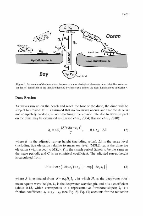
(2002; 2006). Each inlet is represented by six morphological elements (shoals
and bars) plus the inlet channel (Fig. 1). Each morphological element is, in turn,
represented by an actual volume Vx and an equilibrium volume Vxq, where x
stands for a (attachment bars), b (bypass bars), e (ebb shoal), or f (flood shoal).
The flux of sediment out of each morphological element is given by:
x
ox ix
xq
VQ Q
V= (1)
where Qox represents the flux out of the element x and Qix the flux into the
element. In Fig. 1 the transport goes from left to right. A transport rate Qlst is
moving alongshore towards the inlet, which may or may not be stabilized by a
jetty. If there is a jetty, a portion of this sediment Qj will be trapped by the jetty
(thus, when no jetty, Qj=0) whereas the remaining part Qin will enter into the
inlet system. A part of this rate ie in
Q Qδ= , depending on how full the ebb and
flood shoals are, continues to the ebb shoal while the other portion Qic will go
into the inlet channel. This will, in turn, feed the ebb and flood shoals in
proportion to their relative volumes. Unless the system is completely full, a
portion of the incoming rate Qout will leave the inlet system and be transported
further along the beach. If transport rates are going in the opposite direction, the
bars on the left hand side will be activated whereas the ones on the right hand
side will be passive. Initial and equilibrium volumes are specified as input
values to the model as are the respective locations of the attachment bars.
1923
Figure 1. Schematic of the interaction between the morphological elements in an inlet. Bar volumes
on the left-hand side of the inlet are denoted by subscript l and on the right-hand side by subscript r.
Dune Erosion
As waves run up on the beach and reach the foot of the dune, the dune will be
subject to erosion. If it is assumed that no overwash occurs and that the dune is
not completely eroded (i.e. no breaching), the erosion rate due to wave impact
on the dune may be estimated as (Larson et al., 2004; Hanson et al., 2010):
2( ' )
4 ,D
o s D
R h zq C R z h
T
+ ∆ −
= > − ∆ (2)
where R’ is the adjusted run-up height (including setup), ∆h is the surge level
(including tide elevation relative to mean sea level (MSL)); zD is the dune toe
elevation (with respect to MSL); T is the swash period (taken to be the same as
the wave period); and Cs is an empirical coefficient. The adjusted run-up height
is calculated from:
( ) ( )' exp 2 1 exp 2f B D f BR R k s z k s = − + − −
(3)
where R is estimated from =o o
R a H L , in which Ho is the deepwater root-
mean-square wave height, Lo is the deepwater wavelength, and a is a coefficient
(about 0.15, which corresponds to a representative foreshore slope); kf is a
friction coefficient, sB = yB – yD (see Fig. 2). Eq. (3) accounts for the reduction
Up-Drift Barrier Is.
Flood Shoal
Ch
an
ne
l
Bay
OceanEbb Shoal
Down-Drift Barrier Is.
Attach. Bar
Qin
Qie
Qeb
Qba
Qce
Qcf
Qic
Qout
Qfe
Ve , Veq
Vf , Vfq
Attach. Bar
Vla , Vlaq Qlst Qj
1924
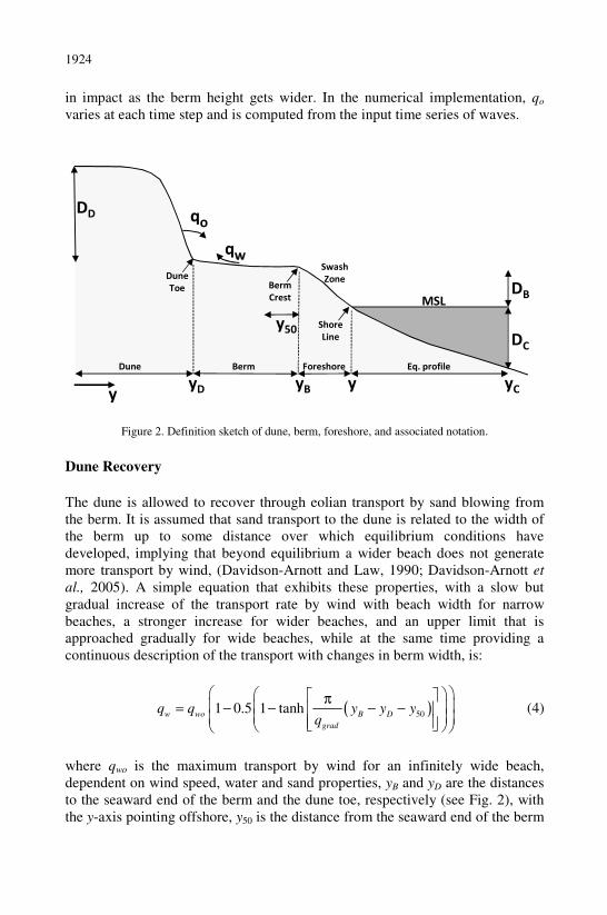
in impact as the berm height gets wider. In the numerical implementation, qo
varies at each time step and is computed from the input time series of waves.
Figure 2. Definition sketch of dune, berm, foreshore, and associated notation.
Dune Recovery
The dune is allowed to recover through eolian transport by sand blowing from
the berm. It is assumed that sand transport to the dune is related to the width of
the berm up to some distance over which equilibrium conditions have
developed, implying that beyond equilibrium a wider beach does not generate
more transport by wind, (Davidson-Arnott and Law, 1990; Davidson-Arnott et
al., 2005). A simple equation that exhibits these properties, with a slow but
gradual increase of the transport rate by wind with beach width for narrow
beaches, a stronger increase for wider beaches, and an upper limit that is
approached gradually for wide beaches, while at the same time providing a
continuous description of the transport with changes in berm width, is:
( )501 0.5 1 tanh
w wo B D
grad
q q y y yq
π
= − − − −
(4)
where qwo is the maximum transport by wind for an infinitely wide beach,
dependent on wind speed, water and sand properties, yB and yD are the distances
to the seaward end of the berm and the dune toe, respectively (see Fig. 2), with
the y-axis pointing offshore, y50 is the distance from the seaward end of the berm
yD yB y yC
Dune Berm Foreshore Eq. profile
DD
MSL
y
DB
DC
Swash
ZoneDune
Toe Berm
Crest
Shore
Line
qo
qw
y50
1925
to where the wind-blown transport has reached 50% of its maximum, and qgrad is
the transport gradient at y50. Bagnold (1954) suggested the transport rate
relationship 3
*/=
wo wq K u g , where *u is the wind shear velocity, g is the
acceleration due to gravity, and Kw is an empirical coefficient that quantifies the
influence of sand properties on the transport rate. Eq. (4) describes a dune that
advances towards the berm crest, although the rate of advance will decrease with
time as the berm width decreases. In the model calculations, qwo is held constant
in time, corresponding to an average wind speed.
Coupling of Processes
Under the assumption that dune and beach profile change occur while
maintaining their respective shape, continuity requires that:
D
B D
B C
Dy y
D D∆ = −∆
+
(5)
where ∆B
y is the berm crest translation corresponding to a dune foot translation
Dy∆ , DD is the dune height, DB is the berm height, and DC is the depth of
closure. This equation provides a simple estimate of the needed profile recession
due to cross-shore processes, from the foot of the dune to the depth of closure, to
produce a certain dune advance, and vice versa. Next, the cross-shore exchange
between the berm and dune is combined with the alongshore sand transport rate
caused by obliquely breaking waves through the continuity equation of shoreline
change:
1 1B
o w bp
B C B C
yy Q Qq q q
t D D x t D D x
∂∂ ∂ ∂ = − + = − − + −
∂ + ∂ ∂ + ∂ (6)
where y is the shoreline location, t is time, Q is the longshore transport rate, and
qbp is a portion of Qout distributed along the beach section inside the down-drift
attachment bar. Thus, the down-drift release of sediment from the tidal inlet
system and the berm translation due to cross-shore interaction between the dune
and berm are linearly added to the contribution by the gradient in longshore
transport rate, /∂ ∂Q x , to obtain the total shoreline temporal evolution.
1926
GenCade Application: Long Island, NY
Background and Method
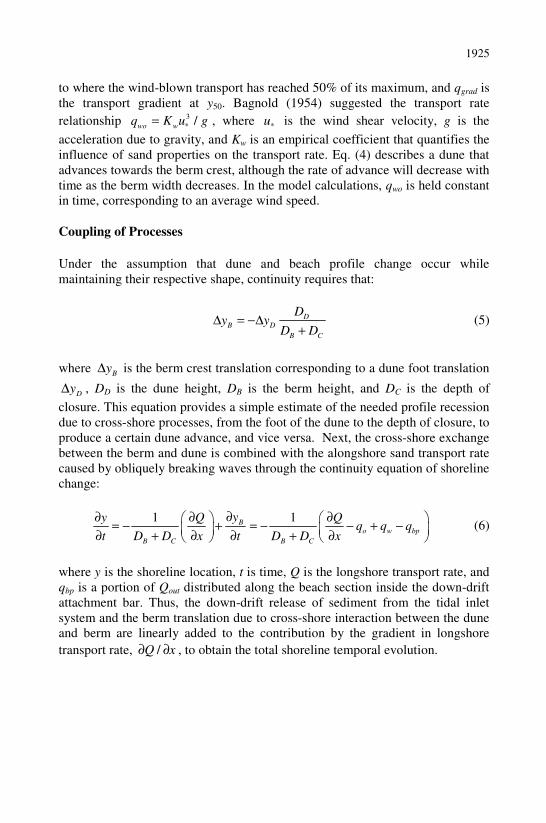
A GenCade model application is presented for the south shore of Long Island,
NY as a validation of relevant processes over multi-decadal time scales. The
south shore of Long Island (Fig. 3) was selected as an appropriate test site for
examining the capabilities of GenCade because of the availability of a long-term
regional coastal database and because the site includes multiple inlets and
barrier islands with coastal structures and ongoing coastal projects that are
maintained at irregular intervals. The data and morphological composition of the
site provide a challenging application to test the unified coastal predictive
capabilities of GenCade. The model domain extends from Montauk Point in the
east to East Rockaway Inlet in the west and includes four inlets: Shinnecock
Inlet, Moriches Inlet, Fire Island Inlet, and Jones Inlet.
Figure 3. Location Map listing all the maintained inlets on the south shore of Long Island.
The wave climate along the south shore of Long Island is characterized by
moderate Atlantic waves typically from the southeast quadrant with a relatively
strong seasonal component of fairly mild waves during summer, severe waves
associated with extratropical storms frequent during winter and spring, and
severe waves associated with tropical storms during fall. Mean wave height over
1927
a 25-year period at NOAA NDBC buoy 44025 is 1.2 m and mean wave period is
8 s. One recent study has estimated 50-year and 100-year return period waves at
16.0 m and 17.1 m, respectively (NYSERDA 2010). Nearshore waves are
substantially reduced in energy as waves shoal across the shelf and Wave
Information Study (WIS) station 50-year storm waves are estimated at 8.7 m.
The wave climate at this location shows that the majority of waves are from the
southeast and the more severe waves associated with extratropical storms are
from the east-southeast. This results in a net westerly longshore transport
direction along the studied coast.
The general trend in grain size characteristics decreases in diameter from
Montauk Point where cobbles are common due to the proximity to the glacial
outwash at the Ronkonkoma moraine. Coarse sand beaches are typical
immediately west of Montauk Point and median grain size changes from
approximately 0.5mm immediately west of Montauk to 0.2 mm in the vicinity of
East Rockaway Inlet (Taney 1961; Morang 1999; USACE 2006). A total beach
fill volume of 1,150,000 m3 has been placed along the beach west of Shinnecock
Inlet from 1983-1995 (Morang 1999) and these are incorporated into the model
simulations.
The simulations generally follow the procedure conducted by Larson et al.
(2002) to determine regional consistency between GenCade and Cascade.
Additional simulations are conducted with the same grid to examine the
sensitivity to ebb shoal excavation of the beach fill material (e.g., dredged from
local inlets within this littoral cell) compared to fill brought in to the littoral
system (e.g., trucked in). The modeling represents sediment bypassing and tidal
shoal evolution at Moriches Inlet and Shinnecock Inlet, as well as 15 groins
along Westhampton, which have interrupted the sediment supply to Moriches
Inlet and Fire Island and require fine spatial resolution to capture relevant
morphology change between the narrowly spaced groins. The present study also
incorporates barrier islands further west of Fire Island Inlet including the
chronically erosive segment also containing groins near Point Lookout west of
Jones Inlet. This section of the grid was developed following the existing
conditions with all groins along Point Lookout Beach, Hempstead Beach, and
Long Beach outlined in Beck and Kraus (2010).
A 12-year simulation (1983-1995) was executed, forced by WIS stations 75, 78,
and 81. There were 934 grid cells, with cell resolution variable alongshore from
approximately 50 m to 200 m, where grid cells with higher resolution applied to
areas with groins and jetties. The computational time step was 1 hour, a constant
grain size of 0.3 mm with an average berm height of 1 m was employed,
constant depth of closure was set to 8 m, and a “pinned” (i.e., no shoreline
change) boundary condition was employed at both lateral ends. Calibration of
1928
the model consisted of first adjusting K1 and K2 values to result in transport
rates that were consistent with sediment budget derived transport rates at various
locations in the domain. Next, calculated shoreline after the simulation was
compared to measured shoreline for agreement. After the initial calibration
period, K1 was set to 0.30 and K2 to 0.15.
Results
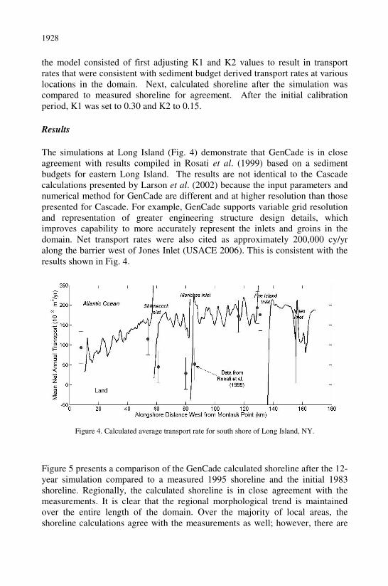
The simulations at Long Island (Fig. 4) demonstrate that GenCade is in close
agreement with results compiled in Rosati et al. (1999) based on a sediment
budgets for eastern Long Island. The results are not identical to the Cascade
calculations presented by Larson et al. (2002) because the input parameters and
numerical method for GenCade are different and at higher resolution than those
presented for Cascade. For example, GenCade supports variable grid resolution
and representation of greater engineering structure design details, which
improves capability to more accurately represent the inlets and groins in the
domain. Net transport rates were also cited as approximately 200,000 cy/yr
along the barrier west of Jones Inlet (USACE 2006). This is consistent with the
results shown in Fig. 4.
Figure 4. Calculated average transport rate for south shore of Long Island, NY.
Figure 5 presents a comparison of the GenCade calculated shoreline after the 12-
year simulation compared to a measured 1995 shoreline and the initial 1983
shoreline. Regionally, the calculated shoreline is in close agreement with the
measurements. It is clear that the regional morphological trend is maintained
over the entire length of the domain. Over the majority of local areas, the
shoreline calculations agree with the measurements as well; however, there are
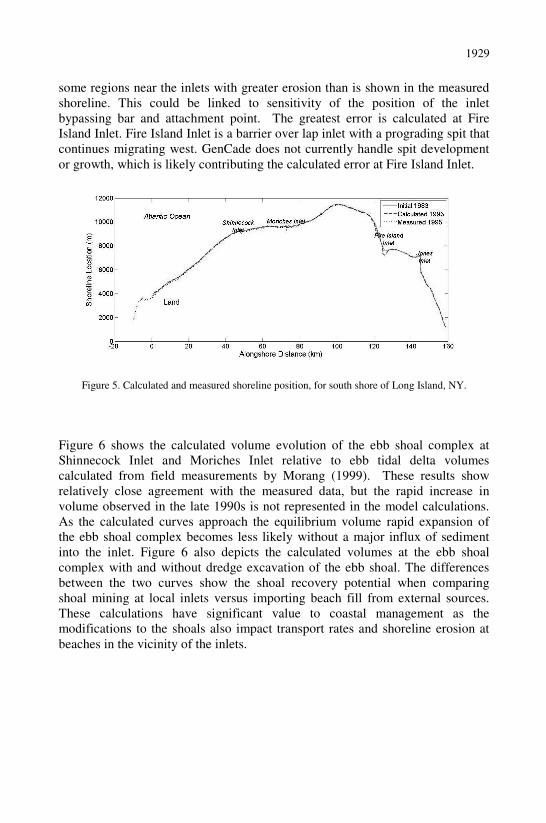
1929
some regions near the inlets with greater erosion than is shown in the measured
shoreline. This could be linked to sensitivity of the position of the inlet
bypassing bar and attachment point. The greatest error is calculated at Fire
Island Inlet. Fire Island Inlet is a barrier over lap inlet with a prograding spit that
continues migrating west. GenCade does not currently handle spit development
or growth, which is likely contributing the calculated error at Fire Island Inlet.
Figure 5. Calculated and measured shoreline position, for south shore of Long Island, NY.
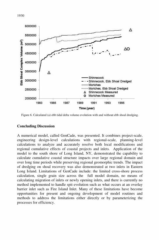
Figure 6 shows the calculated volume evolution of the ebb shoal complex at
Shinnecock Inlet and Moriches Inlet relative to ebb tidal delta volumes
calculated from field measurements by Morang (1999). These results show
relatively close agreement with the measured data, but the rapid increase in
volume observed in the late 1990s is not represented in the model calculations.
As the calculated curves approach the equilibrium volume rapid expansion of
the ebb shoal complex becomes less likely without a major influx of sediment
into the inlet. Figure 6 also depicts the calculated volumes at the ebb shoal
complex with and without dredge excavation of the ebb shoal. The differences
between the two curves show the shoal recovery potential when comparing
shoal mining at local inlets versus importing beach fill from external sources.
These calculations have significant value to coastal management as the
modifications to the shoals also impact transport rates and shoreline erosion at
beaches in the vicinity of the inlets.
1930
Figure 6. Calculated (a) ebb tidal delta volume evolution with and without ebb shoal dredging.
Concluding Discussion
A numerical model, called GenCade, was presented. It combines project-scale,
engineering design-level calculations with regional-scale, planning-level
calculations to analyze and accurately resolve both local modifications and
regional cumulative effects of coastal projects and inlets. Application of the
model to the south shore of Long Island, NY, demonstrated the capability to
calculate cumulative coastal structure impacts over large regional domain and
over long time periods while preserving regional geomorphic trends. The impact
of dredging on shoal recovery was also demonstrated at two inlets in Eastern
Long Island. Limitations of GenCade include: the limited cross-shore process
calculation, single grain size across the full model domain, no means of
calculating migration of inlets or newly opening inlets, and there is currently no
method implemented to handle spit evolution such as what occurs at an overlay
barrier inlet such as Fire Island Inlet. Many of these limitations have become
opportunities for present and ongoing development of model routines and
methods to address the limitations either directly or by parameterizing the
processes for efficiency.
1931
Acknowledgements
This work was supported by the U.S. Army Corps of Engineers, New York
District, and three Research and Development Programs at the Engineering
Research and Development Center: Coastal and Hydraulics Laboratory:
Regional Sediment Management Program, Coastal Inlets Research Program, and
System-Wide Water Resources Program. Permission was granted by
Headquarters, U.S. Army Corps of Engineers, to publish this information. The
authors wish to thank Sophie Munger and Alan Zundel for model development
testing and guidance.
References
Bagnold, R. A. 1954. The physics of blown sand and desert dunes, Methuen &
Co. Ltd., London, 265 pp.
Beck, T.M., and Kraus, N.C. 2010. “GenCade Application at Point Lookout,
NY,” Memorandum for Record 23 September 2010. U.S. Army Engineer
Waterways Experiment Station, Coastal Engineering Research Center,
Vicksburg, MS.
Davidson-Arnott, R.G.D., and Law, M.N. 1990. Seasonal pattern and controls
on sediment supply to coastal foredunes, Long Point, Lake Erie, In:
Nordstrom, K.F., Psuty, N.P., Carter, R.W.G., (Eds.), Coastal Dunes: Form
and Processes, John Wiley & Sons, 177-200.
Davidson-Arnott, R.G.D., MacQuarrie, K., and Aagaard, T. 2005. The effect of
wind gusts, moisture content and fetch length on sand transport on a beach,
Geomorphology, 68, 115-129.
Hanson, H., and Kraus, N. C. 1989. GENESIS: Generalized Model for
Simulating Shoreline Change. Report 1: Technical Reference, Technical
Report CERC-89-19, U.S. Army Engineer Waterways Experiment Station,
Coastal Engineering Research Center, Vicksburg, MS.
Hanson, H., Larson, M., and Kraus, N.C. 2010. Modeling Long-Term Beach
Change under Interacting Longshore and Cross-Shore Processes. Proc. 32nd
Coastal Engineering Conf., World Scientific Press, (in press).
Kraus, N.C. 2000. Reservoir model of ebb-tidal shoal evolution and sand
bypassing, JWPCOE, 126(6), 305-313.
1932
Larson, M., Erikson, L., and Hanson, H. 2004. An analytical model to predict
dune erosion due to wave impact, Coastal Engineering, 51, 675-696.
Larson, M., and Kraus, N.C. 1989. SBEACH: Numerical Model for Simulating
Storm-Induced Beach Change. Report 1: Empirical Foundation and Model
Development, Technical Report CERC-89-9, U.S. Army Engineer
Waterways Experiment Station, Coastal Engineering Research Center,
Vicksburg, MS.
Larson, M., Kraus, N.C., and Hanson, H. 2002. Simulation of regional longshore
sediment transport and coastal evolution – The Cascade model, Proc. 28th
Coastal Engineering Conf., ASCE, 2,612-2,624.
Larson, M., Kraus, N.C., and Connell, K.J. 2006. Modeling Sediment Storage
and Transfer for Simulating Regional Coastal Evolution, Proc. 30th
Coastal
Engineering Conf., ASCE, 3,924-3,936 .
Morang, A. 1999. Shinnecock Inlet, New York, Site Investigation, Report 1,
Morphology and Historical Behavior. Technical Report CHL-98-32, US
Army Engineer Waterways Experiment Station, Vicksburg, MS.
New York State Energy Research and Development Authority (NYSERDA)
2010. Summary of Physical and Environmental Qualities for the Proposed
Long Island-New York City Offshore Wind Project Area. Final Report 10-
22 Summary, AWS Truepower LLC.
Rosati, J.D., Gravens, M.B., and Smith W.G. 1999. Regional sediment budget
for Fire Island to Montauk Point, New York, USA, Proc. Coastal Sediments
´99, ASCE Press, 802-817.
Taney, N.E. 1961. Littoral materials of the south shore of Long Island, New
York. Technical Memorandum No. 129, Beach Erosion Board, U.S. Army
Engineer Waterways Experiment Station, Vicksburg, MS.
USACE. 2006. Limited reevaluation report. Long Beach Island, New York:
Feasibility report. U.S. Army Corps of Engineers, New York District, NY.