cobem-2017-0628 modelling a subsea hydraulic …
TRANSCRIPT

24th ABCM International Congress of Mechanical Engineering December 3-8, 2017, Curitiba, PR, Brazil
COBEM-2017-0628
MODELLING A SUBSEA HYDRAULIC ACTUATOR FOR ULTRA-DEEP
WATER
R. Goularte
V. De Negri Federal University of Santa Catarina, Department of Mechanical Engineering, Florianópolis, Brazil
[email protected] , [email protected]
A. Orth Bosch Rexroth AG, Lohr am Main, Germany
Abstract. The objective of this work is to analyze the dynamic performance of a Subsea Hydraulic Actuator connected
to a Hydraulic Power Unit (HPU) which constitutes a Hydraulic Positioning System using Speed Controlled Pump.
This system is designed to operate on a Wet Christmas Tree (WCT) installed in a depth of 3.300 meters. A detailed
mathematical model was developed representing the system dynamic and static behavior. In this way, the results
obtained through simulation are presented, demonstrating the critical points and advantages of using the selected
layout. The evaluated parameters are the pressures in the hydraulic cylinder chambers, valve operating time response,
positioning capacity of the actuation system, the friction forces acting on the gate valve and the system energy
consumption.
Keywords: Marine and Offshore Systems, Ultra-deep Water, Hydraulic Actuators, Subsea Oil & Gas.
1. INTRODUCTION
Brazilian’s oil and gas exploration industry has grown fast in recent years with the discovery of new reserves in the
pre-salt layer. The investment made by this industry produces a demand for equipment for oil exploration. A great
challenge for pre-salt exploration is the environment where the equipment will be used. The pre-salt reserves are in
regions of maritime ultra-deep water, where the depth corresponds to the range from 1.830 to 3,000 meters. The design
of equipment to operate in these conditions should take into consideration factors such as external high pressure and the
difficult access to perform maintenance. Given these circumstances, the equipment must operate with minimal
corrective action for at least 25 years.
One key equipment for oil production is the Wet Christmas Tree (WCT), which is connected to the subsea
production wellhead. The purpose of the WCT is to control the flow of fluid extracted or injected into the reservoir and
thus ensures proper oil drilling activity. It is noteworthy that WCT also contributes to the sealing of the wellhead in
situations of emergency (leakages or obstruction in the pipeline, electric signal interruption and human error) while
driving oil to the Floating Production Storage and Offloading (FPSO). The flow control of each fluid leaving or entering
the reserve is conducted with the use of an actuator valve. According to Cezar et al (2015) each WCT that will be to
applied in the pre-salt operations has approximately 20 actuators installed, thus guaranteeing a safe operation of the oil
exploration system (Gerngross, 2014; Bai, 2010).
2. SUBSEA ACTUATOR VALVE AND POWER UNIT
The valve actuator structure is composed by three basic elements: valve, bonnet and actuator. The types of such
elements are diverse and their choice will depend on their application in the exploration operation. The actuators can be
of the electrical or hydraulic types and the valves can be accent choke valve, check valve, gate valve or ball valve. So
the bonnet is only a coupling element that makes the connection between the actuator and valve selected. In Figure 1 it
is shown a design of a Subsea Valve Actuator (SVA) assembly which uses a hydraulic actuator operating a gate valve,
such design which will be approached in this work.

R. Goularte, V. De Negri and A. Orth M.S.H. Actuator for Ultra-Deep Water
HPU
BonnetActuator Gate Valve
Figure 1 – Example a Subsea Valve Actuator (SVA).
The gate valve performs an important function regarding to the system safety including, for example, the injection
of chemicals until closing of the well. Therefore, the valve stays closed for short periods. The interruption of power
supplied to the actuators results in the immediate shutdown of production by closing the gate valve. The use of this
valve design is due to the fact that it has a minimal obstruction to the passage of fluids when fully opened which results
in low pressure drop. This is because the shutter acts perpendicular to the fluid flow line. The gate valve is not
recommended for flow control because the intermediate positions promote an abrupt change in fluid velocity through
the valve and the sealing surfaces may suffer erosion wear (Mashiba, 2011).
The hydraulic actuators have the advantages of great reliability, low complexity and the fact that they do not require
power to maintain a specific position once the actuator ports are closed. Additionally, considering the spring installed in
the SVA, no external energy is required to return the actuator in emergency situations. Therefore, the opening and
closing of the valve is carried out by the action of an electro-hydraulic actuator. In Figure 2 an example of hydraulic
circuit of the Hydraulic Positioning System using Speed Controlled Pump (HPS-SCP) is shown.
V1.1
Hydraulic Actuator
Hydraulic Power Unit (HPU)
M
Oil & Gas
Flow
V4
V1.2
P1.1P1.2
V3.2
V2.2
V3.1
V2.1
Z1.2Z1.2
V5.1 V5.2
G
V6
V7
A1.1
V5.3
V5.4
Figure 2 – Diagram of the Hydraulic Positioning System using Speed Controlled Pump (HPS-SCP).
Hydraulic
Cylinder
Housing
Spring
A B
A1
L R
S
B1
24th ABCM International Congress of Mechanical Engineering December 3-8, 2017, Curitiba, PR, Brazil
The hydraulic system is composed of two piloted check valves (V1.1 and V1.2), two relief valves (V2.1 and V2.2)
for safety, six check valves (V3.1, V3.2, V5.1, V5.2, V5.3 and V5.4), two oil filters (Z1.1 and Z1.2), one 2/2 normally
open directional on/off valve (V6), one flow control valve (V7), two pump-motors (P1.1 and P1.2), a cylinder (A1.1), a
gearbox (G) and a servomotor (M). The control of the actuator position is not by a directional valve but by the variation
of the angular velocity of the electric servomotor.
The HPS-SCP follows the hydraulic zone concept that is applied in aviation industry. The concept proposes to
embed the HPU into the actuator. Additionally, this technology eliminates umbilical hydraulic lines and, consequently,
friction losses, and reduces weight and space occupied in topside. This system design has the necessary characteristics
to attend the demand of the oil and gas exploration industry reducing the operational costs in ultra-deep-waters.
3. MATHEMATICAL AND COMPUTATIONAL PROCEDURE
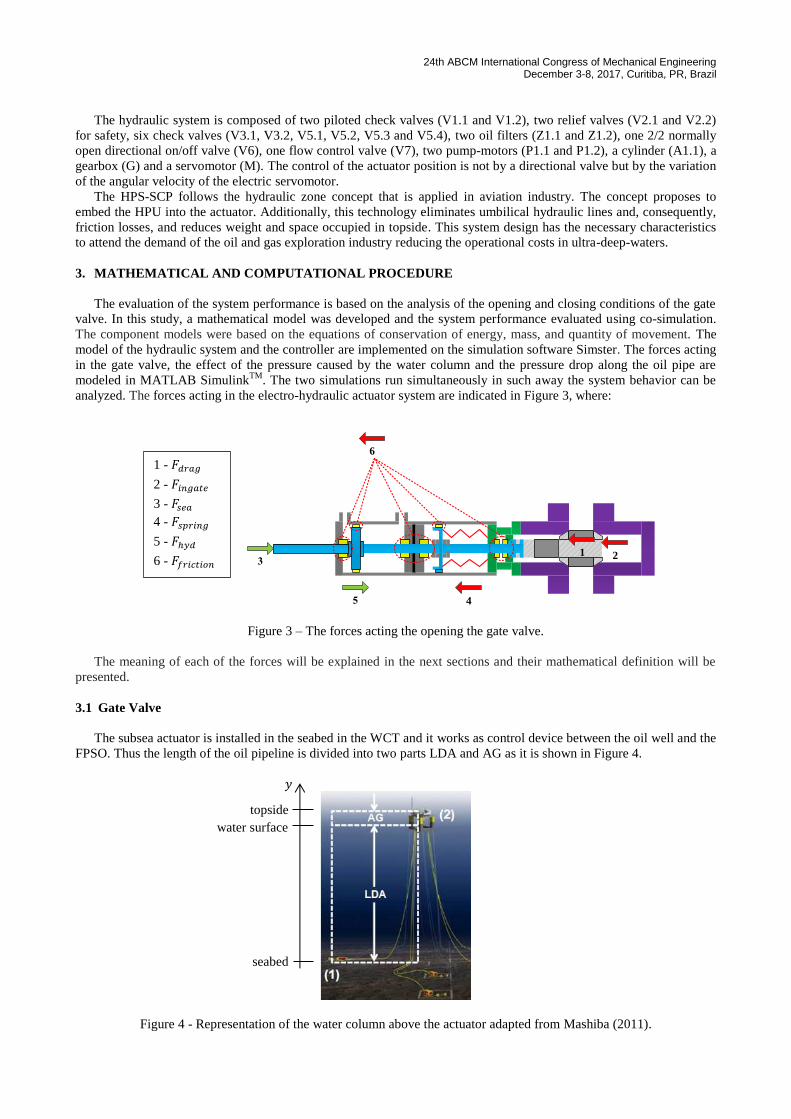
The evaluation of the system performance is based on the analysis of the opening and closing conditions of the gate
valve. In this study, a mathematical model was developed and the system performance evaluated using co-simulation.
The component models were based on the equations of conservation of energy, mass, and quantity of movement. The
model of the hydraulic system and the controller are implemented on the simulation software Simster. The forces acting
in the gate valve, the effect of the pressure caused by the water column and the pressure drop along the oil pipe are
modeled in MATLAB SimulinkTM
. The two simulations run simultaneously in such away the system behavior can be
analyzed. The forces acting in the electro-hydraulic actuator system are indicated in Figure 3, where:
4
6
1 2
Figure 3 – The forces acting the opening the gate valve.
The meaning of each of the forces will be explained in the next sections and their mathematical definition will be
presented.
3.1 Gate Valve
The subsea actuator is installed in the seabed in the WCT and it works as control device between the oil well and the
FPSO. Thus the length of the oil pipeline is divided into two parts LDA and AG as it is shown in Figure 4.
Figure 4 - Representation of the water column above the actuator adapted from Mashiba (2011).
1 - 𝐹𝑑𝑟𝑎𝑔
2 - 𝐹𝑖𝑛𝑔𝑎𝑡𝑒
3 - 𝐹𝑠𝑒𝑎
4 - 𝐹𝑠𝑝𝑟𝑖𝑛𝑔
5 - 𝐹ℎ𝑦𝑑
6 - 𝐹𝑓𝑟𝑖𝑐𝑡𝑖𝑜𝑛
𝑦
water surface
topside
seabed

R. Goularte, V. De Negri and A. Orth M.S.H. Actuator for Ultra-Deep Water
The LDA value represents the distance between the water surface and the point where the WCT is installed. The AG
value represents the distance between the water surface and the oil separation/reservoir in the FPSO for oil storage. The
pressures ( 𝑝1 and 𝑝2 ) at the points (1) and (2) are, respectively, the internal pressure in the oil well ( 𝑝𝑤𝑒𝑙𝑙 = 690 MPa )
and the pressure in the separator in the platform ( 𝑝𝑠𝑒𝑝 = 30 MPa ). The flow of oil along the pipeline can be represented
with the Bernoulli's equation:
𝑝1
𝛾+
𝑣12
2 ∙ 𝑔+ 𝑧1 =
𝑝2
𝛾+
𝑣22
2 ∙ 𝑔+ 𝑧2 + ℎ𝑣𝑎𝑙𝑣𝑒 + ℎ𝑙𝑖𝑛𝑒 (1)
where ℎ𝑣𝑎𝑙𝑣𝑒 is the minor loss in the gate valve, ℎ𝑙𝑖𝑛𝑒 is the loss due to the friction of the production fluid with the inner
surface of the pipeline, g is gravitational acceleration, v1 is the velocity of the fluid inside the oil reservoir (v1 ≅ 0) , v2
is the velocity of the fluid at the inlet of the oil separator, γ is the specific weight of the production fluid, z1 is the
position of the hydraulic actuator (z1 = 0) and z2 is the position of the oil separator.
Manipulating Eq. 1 gives the equation of average velocity of the oil flow along the pipeline. In the analysis of this
study the pipeline length (L) was considered 13 km. ρFP is the specific mass of the production fluid. However, to
determine the average velocity, it is necessary to know the pressure loss coefficient at the valve (K) and the pipeline
friction factor (f). Both variables are dependent on the position of the gate valve.
𝑣(𝑥) = √2[(𝑝1 − 𝑝2) − 𝜌𝐹𝑃 ∙ 𝑔 ∙ (𝐿𝐷𝐴 + 𝐴𝐺)]
𝜌𝑜𝑖𝑙 ∙ (1 + 𝐾(𝑥) + 𝑓(𝑥) ∙𝐿𝐷
) (2)
The friction factor is determined by the solution of Eq. 3, it is known as implicit Colebrook-White equation.
1
√f(x)= -2∙ log (
ε
3.7∙D+
2.51∙ν
v(x)∙D∙√f(x) ) (3)
where D is the pipeline diameter, ν is the kinematic viscosity of the production fluid and ε is the average roughness of
the inner wall of the pipeline.
The determination of the valve pressure drop is proportional to the position opening of the gate valve. Fig. 5 shows
all stages of the gate valve opening.
Figure 5 - Representation of the stages an gate valve (a) closed, (b) crack-open, (c) semi-open and (d) completely open.
When the shutter is in the position x = 0, the valve is fully closed and flow rate is zero. x = xCO is the crack-open
moment that initiates the passage of fluid through the valve and x = xTOT represents the valve fully opening and the
losses are minimal. According to Mashiba (2011), the valve load loss coefficient depends on the percentage of opening
of the gate valve, that is:.
𝐾(𝑥) = 1984. 𝑒−0.735.ℎ(𝑥)0.545+ 0.1 (4)
where the variation of the minor loss is proportional to the percentage of opening:
x = 0
x = xCO x = xTOT
xCO < x < xTOT
𝑥
(a)
(b)
(c)
(d)

24th ABCM International Congress of Mechanical Engineering December 3-8, 2017, Curitiba, PR, Brazil
ℎ(𝑥) = |0 𝑖𝑓 0 < 𝑥 ≤ 𝑥𝑐𝑜
𝑥 − 𝑥𝑐𝑜
𝑥𝑡𝑜𝑡 − 𝑥𝑐𝑜. 100 𝑖𝑓 𝑥𝑐𝑜 < 𝑥 ≤ 𝑥𝑡𝑜𝑡
(5)
Therefore, the downstream pressure at the gate valve can be determined by
𝑝𝑗(𝑥) = |
𝑝𝑠𝑒𝑝 + 𝜌𝑜𝑖𝑙 ∙ 𝑔 ∙ (𝐿𝐷𝐴 + 𝐴𝐺)
𝑝𝑚 − 𝐾(𝑥) ∙ 𝜌𝑜𝑖𝑙 ∙𝑣2(𝑥)
2
𝑖𝑓 0 ≤ 𝑥 < 𝑥𝑐𝑜
𝑖𝑓 𝑥𝑐𝑜 ≤ 𝑥 < 𝑥𝑡𝑜𝑡
(6)
where 𝑝𝑠𝑒𝑝 is the pressure on the surface separator install in the topside. Knowing the gate valve upstream and
downstream pressures, it is possible to determine the pressure differential and the drag frictional force (Fdrag). As
illustrate in the Fig. 3 the friction force is due to the contact between the seals with the seat of gate valve. This force is
the main component of the total friction force.
𝐹𝑑𝑟𝑎𝑔(𝑥) = 𝐴𝐺𝑎𝑡𝑒𝑉𝑎𝑙𝑣𝑒(𝑥) ∙ (𝑝𝑤𝑒𝑙𝑙 − 𝑝𝑗(𝑥)) (7)
where 𝐴𝐺𝑎𝑡𝑒𝑉𝑎𝑙𝑣𝑒 is it is the difference between maximum area with the oil pass-through of the gate valve.
The valve body cavity always has internal pressure equal to the upstream pressure as illustrate in the Fig. 3. The
pressure acting on the area of rod cross section is the pressure in the oil reservoir, i.e. the pressure upstream of the
valve, resulting on a force expressed by
𝐹𝑖𝑛𝑔𝑎𝑡𝑒 =𝜋
4∙ 𝐷𝐻𝑃
2 ∙ 𝑝𝑤𝑒𝑙𝑙 (8)
The actuator is subjected to the environment pressure, i.e. the external pressure to the actuator is equivalent to the
pressure coming from the water sea column above it. The actuator used a symmetric cylinder as shown in Fig. 3; the
actuator rod is exposed to the marine environment. Therefore, there is external force acting on the actuator, which is
defined by Equation 9.
𝐹𝑠𝑒𝑎 =𝜋
4. 𝐷𝑟𝑜𝑑
2 . 𝜌𝑠𝑒𝑎 . 𝑔. 𝐿𝐷𝐴 (9)
where D𝑟𝑜𝑑 is the diameter of the actuator rod and ρsea is the density of sea water.
3.2 Electro-Hydraulic Actuator
A typical spring used in ultra-deep waters is a Belleville spring. It has the ability to tolerate high compression loads
and has a compact geometry. However, it presents a nonlinear load behavior when force is correlated to deformation.
The force of deformation is presented in Eq.10 where, k1 and k2 are spring constants and L1 is the initial preload spring
compression. The preload will ensure the positioning of the closed valve when it is fully closed during a normal or
emergency operation situation.
Fspring(x) = k1. (L1 − x(t))2 + k2. (L1 − x(t)) (10)
The hydraulic force is defined by the pressure differential between the pressures 𝑝𝑎 and 𝑝𝑏 in the cylinder chambers,
resulting on
𝐹ℎ𝑦𝑑𝑟𝑎𝑢𝑙𝑖𝑐(𝑡) = 𝐴𝑐𝑦𝑙𝑖𝑛𝑑𝑒𝑟(𝑡) ∙ [ 𝑝𝑎(𝑡) − 𝑝𝑏(𝑡) ] (11)
The friction force (𝐹𝑓𝑟𝑖𝑐𝑡𝑖𝑜𝑛) includes the friction at the actuator and bonnet. Thus the parameters were inserted in
the mathematical model of hydraulic cylinder friction.
3.3 DC Motor
According to Chen et al (2011) the Brushless DC Motor (BLDC) present lower cost and mid-size. It fits perfectly
when the implementation is on a Subsea Actuator Valve with compact dimensions and at an reasonable cost.
Furthermore, the rotational frequency control can be easily implemented in a brushless motor. With the electric voltage

R. Goularte, V. De Negri and A. Orth M.S.H. Actuator for Ultra-Deep Water
supplied, it is possible to control the speed of operation in a simple way. Eq. 12 represents the voltage balance equation
for the DC motor.
𝑉𝑖𝑛(𝑡) = 𝐾𝑒 ∙ �̇�(𝑡) + 𝑅 ∙ 𝑖𝑎(𝑡) + 𝐿 ∙𝑑𝑖𝑎
𝑑𝑡 (12)
where, R and L are the resistance and inductance of the windings respectively, Vin is voltage, i𝑎 current, θ̇ is the
electrical angular velocity and Ke is the BEMF (Back Electromotive Force) constant.
The mechanical movement equation is represented by
𝑇𝑚𝑒𝑐(𝑡) = 𝑇𝑒𝑙𝑒𝑡𝑟𝑖𝑐(𝑡) − 𝐵 ∙ �̇�(𝑡) − 𝑇𝑙𝑜𝑎𝑑(𝑡) (13)
where Tmec(t) is the mechanical torque, Teletric is the torque electric, B is a viscous friction and Tload is torque load.
One of the focuses of this paper is the analysis power consumed by the system. The consumed electric power can be
defined by Eq. 14
𝑃𝑒𝑙𝑒𝑡𝑟𝑖𝑐(𝑡) = 𝑉𝑖𝑛(𝑡) ∙ 𝑖𝑎(𝑡) (14)
where Peletric electric power that is supplied to the DC motor, Vin the voltage defined by the control for the rotation
control of the electric motor and i the electric current in the electric motor.
4. RESULTS AND DISCUSSION
A trapezoidal signal was used as a reference for opening and closing the gate valve. This type of signal was choose
to be avoiding the peaks of electric current and, consequently, reducing the power consumed by the electric motor.
Furthermore, this type of signal avoids the propagation of shockwaves as when it has a rapid opening or closing of the
gate valve. It can promote the release/containment of a significant amount of energy from the oil well to the pipeline.
The reference signal and the ability of the proposed system on controlling the actuator position directly by speed
control of pumps are analyzed in the Fig. 6a). It shows the overlapped between the position of the hydraulic cylinder
and the reference signal.
Figure 6 – Positon and error for electro-hydraulic actuator.
The maximum positioning error identified during the opening and closing process of the gate valve was 0.1% for the
operating condition of 3,330 meters depth than it is showing in Fig.6b). The low error values obtained are directly
related to the use of the brushless DC motor because it has a fast dynamic response, allowing the correction of the
trajectory even with the oscillations of load during the opening and closing of the gate valve. The maximum time set for
each operation, opening and closing, was 60 seconds. The power consumptions for depths of 2,600 and 3,300 meters are
showing in the Fig. 8.
(a)
(b)

24th ABCM International Congress of Mechanical Engineering December 3-8, 2017, Curitiba, PR, Brazil
Figure 7 – Power consumed for depths of 2.600 and 3.300 meters..
The increase in consumption at lower depth was approximately 30% since the force exerted by the water column
helps the opening movement of the actuator according to Eq.9.. However, in the return of the actuator the energy
consumption remained similar for both situations since the force provided by the mechanical spring assists the
return movement. Pumps P1.1 and P1.2 perform the control of the speed with which the hydraulic cylinder
returns. The power values found refers only to the actuator movement and do not represent the total system
consumption that would include the energy supply to temperature, pressure, contaminant, position and frequency
sensors. The power consumption is lower than 200 W, which it is the maximum limit needed from the Subsea
Module Control (SCM). An evaluation based only on the power consumed by the actuation system is not totally representative. So it is
necessary to determine the energy consumed during an operating cycle. The following equations are used to calculate
the energy consumption in the system:
𝐸𝑐(𝑡) = ∫ 𝑞𝑐(𝑡) ∙ ∆𝑝𝑐(𝑡) ∙ 𝑑𝑡 (15)
𝐸𝑙(𝑡) = ∫ 𝑓𝑐 ∙ ∆𝑝𝑐2(𝑡) ∙ 𝑑𝑡 (16)
𝐸𝑖𝑛(𝑡) = ∫ 𝑉𝑖𝑛(𝑡) ∙ 𝑖𝑎(𝑡) ∙ 𝑑𝑡 (17)
𝐸𝑔(𝑡) = ∫ 𝑇𝑔(𝑡) ∙ 𝜔𝑔(𝑡) ∙ 𝑑𝑡 (18)
where 𝐸𝑐 is the energy dissipated in the component, 𝑞𝑐 is the flow rate through the hydraulic component, ∆𝑝𝑐 is the
pressure differential in the hydraulic components, 𝐸𝑙 is the energy dissipated as internal leakage, 𝐸𝑖𝑛 is the electric
energy at system, 𝐸𝑔 is the dissipated energy in the transmission box, 𝑇𝑔 is the mechanical torque and 𝜔𝑔 the axis
rotation. In Figure 9, the energy distributions are determined for an SVA during an operating cycle, allowing to
understand the main sources of system energy losses. It consists of the complete opening and closing movement of the
gate valve at a depth of 3,330 meters.

R. Goularte, V. De Negri and A. Orth M.S.H. Actuator for Ultra-Deep Water
Figure 8 – Diagram showing the distribution of energy in SAV.
The main source of energy loss is at the electrical machine with 21.7%. The frequency converter loss is not included
in this study. According to Minav (2015), the DC motor has two types of losses. Electrical machine losses are
composed of the stator and rotor resistive losses, iron losses and additional losses. Mechanical losses include friction in
the motor bearings what is dependent on the shaft speed, bearing type, properties of the lubricants and the load.
The second largest source of energy loss is valve V1.1 and it is represented in the Fig. 10 with the gauge pressures at
three points (L, R and A1) in the hydraulic circuit.
Figure 9 – Gauge pressure at points A, A1 and R.
During the opening of gate valve, in the range of 2 to 62 seconds, there is a small pressure differential between the
points upstream (𝐴1) and downstream(𝐴). The small pressure difference comes from the check valve (V3.1) with a pre-
charge pressure (p0). However, there is a discrepancy of the pressures in the range of 75 to 130 seconds. It indicates that
valve V1.1 restricts the passage of hydraulic fluid. This behavior modifies the mechanism for controlling the actuator
return speed. The control should be done by pump P1.1 but it is carried out by V1.1. The check valve throttle the
hydraulic fluid passage and the energy present in the hydraulic fluid is dissipated as heat. The effect of the restriction is
T
o
t
a
l
E
n
e
r
g
y
Useful Energy (42,60 %)
DC Motor (21,70 %)
V1.1 (19,30 %)
Gearbox (3,80 %)
V5.3 (1,45 %)
V5.2 (1,45 %)
V5.1 (1,45 %)
Leakage (0,81 %)
Friction (3,54 %)
V5.4 (1,45 %)
V1.2 (1,00 %)
V3.2 (1,45 %)

24th ABCM International Congress of Mechanical Engineering December 3-8, 2017, Curitiba, PR, Brazil
a consequence of the low pilot pressure which it is insufficient for the unlocking of the valve V1.1. The procedure for
opening by pilot is presented in Eq. 19 which defines percentage to open of the piloted check valve.
𝑢 = |
0
(𝑝𝐴1 − 𝑝𝐴−𝑝0 + (𝑝𝑅 − 𝑝𝐴1) ∙ 𝑅
𝑑𝑝)
𝑖𝑓 (𝑝𝑅 − 𝑝𝐴1) ≤ 0
𝑖𝑓 (𝑝𝑅 − 𝑝𝐴1) > 0
(19)
where R is the pilot area ratio, p0 is the preload and dp the spring constant of the check valve.
The valve opening occurs when (𝑝𝑅 − 𝑝𝐴1) > 0 . However, the differential pressure at point A and A1 are high as
shown in Fig. 10. This behavior demands a higher pressure in the pilot which it is not achieved. The hydraulic force is
not effective because the spring force assisted for the return movement. Consequently, there is a low pressure at the
point B and R. The problem could be solved with increasing the value of the relation of areas of the pilot but the valves
selected have the bigger ratio of areas of pilot offered in the catalog of the manufacturer.
5. CONCLUSIONS
The layout of a HPS-SCP has dynamic and static behavior in the observed conditions. The position control
capability is dependent on the fast dynamics of the pump drive system; this is achieved due the characteristics of the DC
Brushless Motor. The paper demonstrates that the simulation is a useful tool to evaluate and to consolidate the
development of new mechanical systems and maybe the model can help to reduce the final costs of project. For a
second phase of this project, experimental tests should be carried out for improving and validating the developed
mathematical model. The model will be used to determine energy consumption at other elements present in the SAV
such as sensors and frequency inverter.
6. ACKNOWLEDGEMENTS
The research was enabled by the financial support of CNPq and technical support of Bosch Rexroth AG.
7. REFERENCES
Gerngross, R and Orth, A., 2014. “Design of safe and reliable hydraulic systems for subsea applications”. 10 Nov 2015
<https://dc-us.resource.bosch.com/media/us/trends_and_topics_2/technical_papers/marine_offshore/deepseahydra
ulics.pdf>.
Bai, Y. and Bai, Q., 2010. Subsea Engineering Handbook. Elsevier, Houston, 1st edition.
Cezar, A. et al, 2015. “Subsea solution in the Pre-salt development projects”. In Proceeding of the Offshore Technology
Conference – OTC2015. Houston.
Mashiba, M.H.D., The influence of the operating and design parameters in the hydraulic actuation performance of
subsea gate valves. Master thesis, Federal University of Rio de Janeiro, Rio de Janeiro, Brazil.
Chen, C.H.; Chi, W.C.; Cheng, M.Y., “Regenerative braking control for light electric vehicles”. In Proceeding of the
9th International Conference Power Electronics and Drive Systems. Singapore.
Minav, T.A.; Heikkinen, J.E., Pietola, M. “Chapter 6 - Electric-driven Zonal Hydraulics in Non-Road Mobile
Machinery”. In New Applications of Electric Drives, Dr. Miroslav Chomat, InTech, 2015. DOI: 10.5772/61793
8. RESPONSIBILITY NOTICE
The author(s) is (are) the only responsible for the printed material included in this paper.