cobf 0127 1-27 - · pdf file• comes standard with apollo ... y-strainer 0-standard 1-w/...
TRANSCRIPT

backflow preventers
2
Backflow Preventers
Customer Service 1-704-841-6000
TABLE OF CONTENTS
Selection Guide . . . . . . . . . . . . . . . . . . . . . . . . . . . . . . . . . . . . . . . . . . . . . . . . . . . . . . . . . . . . . . . . . . . . . . . .3
Double Check Valve (Series 40-100) . . . . . . . . . . . . . . . . . . . . . . . . . . . . . . . . . . . . . . . . . . . . . . . . . . . . .4,5
Double Check Valve (Model DC) . . . . . . . . . . . . . . . . . . . . . . . . . . . . . . . . . . . . . . . . . . . . . . . . . . . . . . . . .6-8
Reduced Pressure Principle (Series 40-200) . . . . . . . . . . . . . . . . . . . . . . . . . . . . . . . . . . . . . . . . . . . . . .9-18
Dual Check Valve (Series 40-300) . . . . . . . . . . . . . . . . . . . . . . . . . . . . . . . . . . . . . . . . . . . . . . . . . . . . . . . .19
Carbonated Beverage Backflow Preventer (Series 4C-100) . . . . . . . . . . . . . . . . . . . . . . . . . . . . . . . . . . . .20
Spill Resistant Pressure Vacuum Breaker (Series 4W-500) . . . . . . . . . . . . . . . . . . . . . . . . . . . . . . . . . . . .21
Continuous Pressure Backflow Preventer (Series 40-400) . . . . . . . . . . . . . . . . . . . . . . . . . . . . . . . . . . . . .22
Pressure Type Vacuum Breaker (Series 4V-500) . . . . . . . . . . . . . . . . . . . . . . . . . . . . . . . . . . . . . . . . . .23-24
Double Check Detector Assembly (Model DCDA) . . . . . . . . . . . . . . . . . . . . . . . . . . . . . . . . . . . . . . . . .25-26
Reduced Pressure Detector Assembly (Series 40-700) . . . . . . . . . . . . . . . . . . . . . . . . . . . . . . . . . . . . .27-28
Hose Connection Vacuum Breaker (Series 38) . . . . . . . . . . . . . . . . . . . . . . . . . . . . . . . . . . . . . . . . . . . . . .29
Hose Connection Vacuum Breaker (Series 38-304-02) . . . . . . . . . . . . . . . . . . . . . . . . . . . . . . . . . . . . . . . .30
Atmospheric Type Vacuum Breaker (Series 38-100) . . . . . . . . . . . . . . . . . . . . . . . . . . . . . . . . . . . . . . . . . .31
Atmospheric Type Vacuum Breaker (Series 38-200) . . . . . . . . . . . . . . . . . . . . . . . . . . . . . . . . . . . . . . . . . .32
Lab Faucet Vacuum Breaker (Series 38-500) . . . . . . . . . . . . . . . . . . . . . . . . . . . . . . . . . . . . . . . . . . . . . . .33
Freeze Protection Valve (Series 40-000) . . . . . . . . . . . . . . . . . . . . . . . . . . . . . . . . . . . . . . . . . . . . . . . . . . .34
Backflow Preventer Test Kits . . . . . . . . . . . . . . . . . . . . . . . . . . . . . . . . . . . . . . . . . . . . . . . . . . . . . . . . . . . .35
Test Kit Accessories and Flanged Ball Valve (Series IBVE-125) . . . . . . . . . . . . . . . . . . . . . . . . . . . . . . . . .36
Air Gap Drain . . . . . . . . . . . . . . . . . . . . . . . . . . . . . . . . . . . . . . . . . . . . . . . . . . . . . . . . . . . . . . . . . . . . . . . .37
Meter Setter . . . . . . . . . . . . . . . . . . . . . . . . . . . . . . . . . . . . . . . . . . . . . . . . . . . . . . . . . . . . . . . . . . . . . . . . .38
4S Valve Setter . . . . . . . . . . . . . . . . . . . . . . . . . . . . . . . . . . . . . . . . . . . . . . . . . . . . . . . . . . . . . . . . . . . . . . .39
Thermal Expansion Relief Valves . . . . . . . . . . . . . . . . . . . . . . . . . . . . . . . . . . . . . . . . . . . . . . . . . . . . . . . . .40
3/4" Hose Connection Pressure Gauge & Thermal Expansion Tank . . . . . . . . . . . . . . . . . . . . . . . . . . . . . .41
“Y” Strainers . . . . . . . . . . . . . . . . . . . . . . . . . . . . . . . . . . . . . . . . . . . . . . . . . . . . . . . . . . . . . . . . . . . . . . . . .42
Approvals . . . . . . . . . . . . . . . . . . . . . . . . . . . . . . . . . . . . . . . . . . . . . . . . . . . . . . . . . . . . . . . . . . . . . . . . . . .43
Warranty and Limitations of Liability . . . . . . . . . . . . . . . . . . . . . . . . . . . . . . . . . . . . . . . . . . . . . . . . . . . . . . .44
Notes . . . . . . . . . . . . . . . . . . . . . . . . . . . . . . . . . . . . . . . . . . . . . . . . . . . . . . . . . . . . . . . . . . . . . . . . . . . .45-47

3
Backflow Preventers
Customer Service 1-704-841-6000
SE
LE
CT
ION
GU
IDE
AP
PL
ICA
TIO
N
SERI
ESBa
ckBa
ckCo
ntin
uous
Low
High
SIZE
AVAI
LABL
ESi
phon
age
Pres
sure
Pres
sure
Haza
rdHa
zard
1 /43 /8
1 /23 /4
11-
1 /41-
1 /22
2-1 /2
34
68
10
40-1
00✓
✓✓
✓✓
4C-1
00✓
✓
4S-1
00✓
✓✓
✓✓
✓✓
40-2
00✓
✓✓
✓✓
✓✓
✓✓
✓✓
✓✓
✓
40-2
00✓
✓✓
✓✓
40-2
00✓
✓✓
✓✓
40-3
00✓
✓✓
40-4
00✓
✓
4V-5
00✓
✓✓
✓✓
✓
4W-5
00✓
✓✓
4S-6
00✓
✓✓
✓✓
✓
40-7
00✓
✓✓
✓✓
38-1
00✓
✓✓
✓✓
✓✓
✓
38-2
00✓
✓✓
✓
38-3
04✓
38P
38-3
04-0
2✓
38-4
04✓
38-5
00✓
✓
TYPE
OF
DEVI
CE
DOUB
LE C
HECK
VAL
VECA
RBON
ATED
BEV
ERAG
EBA
CKFL
OW P
REVE
NTER
DOUB
LE C
HECK
VAL
VERE
DUCE
D PR
ESSU
REPR
INCI
PLE
REDU
CED
PRES
SURE
PRIN
CIPL
E (S
tn.S
teel)
REDU
CED
PRES
SURE
PRIN
CIPL
E (U
& Z
Flo
w)DU
AL C
HECK
VAL
VECO
NTIN
UOUS
PRE
SSUR
EPR
ESSU
RE T
YPE
VACU
UM B
REAK
ERSP
ILL-
RESI
STAN
T PR
ESS.
VA
C. B
REAK
ERDO
UBLE
CHE
CKDE
TECT
OR A
SSEM
BLY
REDU
CED
PRES
SURE
DETE
CTOR
ASS
EMBL
YAT
MOS
PHER
IC T
YPE
VACU
UM B
REAK
ERAT
MOS
PHER
IC T
YPE
VACU
UM B
REAK
ERHO
SE C
ONNE
CTIO
N VA
CUUM
BRE
AKER
HOSE
CON
NECT
ION
BACK
FLOW
PRE
VENT
ERAN
TI F
REEZ
E HO
SE C
ONN.
VAC.
BRE
AKER
LAB
FAUC
ET
VACU
UM B
REAK
ER
*
*Onl
y to
be
used
on
syst
ems
whe
re th
e lo
w-h
ead
back
-pre
ssur
e do
es n
ot e
xcee
d th
at g
ener
ated
by
an e
leva
ted
hose
equ
al to
or
less
than
3m
(10
ft) in
hei
ght

4
Backflow Preventers
Customer Service 1-704-841-6000
40-100-T2 Series TOP ENTRY T2 DOUBLE CHECK VALVE ASSEMBLYThe Conbraco Series 40-100 Top Entry T2 Double Check Valve Assembly is designed to protect against backflow from a cross-connection of non-health hazard pollutant. Within theassembly are two mechanically independent, spring-loaded poppet type check valves set in an integral cast bronze body. Both check valves are designed at an inclined angle upward from horizontal centerline of the assembly, and all test cocks are mounted at the top to assure easyaccess during repair and maintenance when unit is installed in a pit or tight places.
OPERATIONDuring normal flow conditions, the two check valves are held off their seats, supplying waterdownstream. Each check valve is designed to maintain a minimum of 1 psi across the valve during normal operation. Should the downstream pressure increase to within 1 psi of supplypressure, both check valves will close to prevent a backflow condition.
FEATURES• Top access for testing, repair
and maintenance• Corrosion resistant• Low head loss• Interchangeable poppets and springs
• Replaceable seats• Comes standard with Apollo® full port
ball valves with stainless steel handles• Maximum working pressure 175 psig• Temperature range 33°F-180°F
Dimensions (in) – Weights (lbs.)Body Size 3/4" 1" 1-1/4" 1-1/2" 2"A 14-1/4 14-3/4 20-3/4 21-3/8 23-1/8B 7-1/4 7-1/4 12-3/8 12-3/8 12-3/8C 4-5/16 4-5/16 6-1/8 6-1/8 6-1/8D 1-5/8 1-7/8 2-3/16 2-5/8 3E 2-7/16 2-7/16 3-13/16 3-13/16 3-13/16F 5-7/16 5-7/16 6-3/8 6-3/8 6-3/8G 13/16 13/16 1-3/8 1-3/8 1-3/8Test Cocks 1/8 x 1/4 NPT 1/8 x 1/4 NPT 1/4 x 1/4 NPT 1/4 x 1/4 NPT 1/4 x 1/4 NPTNet Weight 8.8 9.5 23.2 25.7 31.5Shipping Weight 10.1 10.8 25.9 28.8 35.5
40 - 1 X X - TXY-STRAINER0-Standard1-w/ Y-strainer (shipped loose)
NON UL CLASSIFIED1-less ball valves2-w/ball valves4-w/union end ball valves
FOR UL CLASSIFIEDFP1-less ball valvesFP2-w/ball valves
SIZE4-3/4"5-1"6-1-1/4"7-1-1/2"8-2"
Flow Curves : (*) Rated flow as determined by USC’s FCCC&HR and ASSE design performance standards.
MATERIALSBody and covers BronzeSprings Stainless SteelPoppets Glass-Filled CelconSeat discs Silicone RubberReplaceable seats Glass-Filled NorylFasteners Stainless Steel
Sizes 3/4", 1", 1-1/4", 1-1/2", 2"
40-100 Series

5
Backflow Preventers
Customer Service 1-704-841-6000
40-100-TC2 Series TOP ENTRY TC2 DOUBLE CHECK VALVE ASSEMBLYThe Conbraco Series 40-100 Top Entry TC2 Double Check Valve Assembly, with SAE threadedhose connections make certification testing fast and trouble-free. It is designed to protect againstbackflow from a cross-connection of non-health hazard pollutant. Within the assembly are twomechanically independent, spring-loaded poppet type check valves set in an integral cast bronzebody. Both check valves are designed at an inclined angle upward from horizontal centerline of the assembly, and all test cocks are mounted at the top to assure easy access during repair andmaintenance when unit is installed in a pit or tight places.
OPERATIONDuring normal flow conditions, the two check valves are held off their seats, supplying water down-stream. Each check valve is designed to maintain a minimum of 1 psi across the valve during normal operation. Should the downstream pressure increase to within 1 psi of supply pressure,both check valves will close to prevent a backflow condition.
FEATURES• Top access for testing, repair
and maintenance• Corrosion resistant• Low head loss• Interchangeable poppets and springs
• Replaceable seats• Comes standard with Apollo® full port
ball valves with stainless steel handles• Maximum working pressure 175 psig• Temperature range 33°F-180°F
Dimensions (in.) – Weights (lbs.)Body Size 3/4" 1"A 13 14-3/4B 7-1/4 7-1/4C 4-1/4 4-5/16D 1-11/16 1-7/8E 2-7/16 2-7/16F 5-5/8 5-11/16G 1-3/16 1-7/8Test Cocks 1/8 x 1/4 SAE 1/8 x 1/4 SAENet Wt. 8-7/8 9-1/2Shpg. Wt. 10-1/8 11
40 - 1 X X - TC2
Y-STRAINER0-Standard1-w/ Y-strainer (shipped loose)
SIZE4-3/4"5-1"
Flow Curves : (*) Rated flow as determined by USC’s FCCC&HR and ASSE design performance standards.
MATERIALSBody and covers BronzeSprings Stainless SteelPoppets Glass-Filled CelconSeat discs Silicone RubberReplaceable seats Glass-Filled NorylFasteners Stainless Steel
Sizes 3/4" - 1"
40-100 Series

Model DC
DC Series TOP ENTRY DOUBLE CHECK VALVE ASSEMBLYThe Conbraco Model DC Double Check Valve Backflow Preventer is designed to prevent back-flow by either back-pressure or backsiphonage from a cross-connection between potable waterlines and substances that are objectionable, but not a health hazard. It is an economical devicethat is easily repaired in the line. The device consists of two independently acting, spring-loadedpoppet type check valves in an integral cast bronze body. Four test cocks and two shut-off valveswhich are quarter-turn, full-port, resilient-seated and ball type complete the assembly.
OPERATIONDuring normal flow conditions, the two check valves are held off their seats, supplying water down-stream. Each check valve is designed to maintain a minimum of 1 psid across the valve during normal operation. If at any time the pressure downstream of the device increases to within 1 psi of supply pressure, both check valves will close to prevent a backflow condition from occurring.
FEATURES• Corrosion resistant• Easy to install, repair and maintain• Low head loss• Replaceable check modules
• Comes standard with Apollo® full-port ball valves with stainless steel handles
• Maximum working pressure 175 psig• Operating temperature range 33°F-180°F
4S - 1 0 3 - A X
BALL VALVES1 -less ball valves2 -w/ ball valves4 -w/ union end ball valves
Dimensions (in.) – Weights (lbs.)Body Size 1/2"A (w/o Ball Valves) 5-5/8B 9-3/4C 4-1/2D 3-1/2E 1F 3-5/8Net Wt. (w/o Ball Valves) 2.68Net Wt. (with Ball Valves) 4.38Shpg. Wt. (w/o Ball Valves) 3.8Shpg. Wt. (with Ball Valves) 5.1
Flow Curves :
Sizes 1/2"
MATERIALSBody and Cover BronzeCheck Modules Acetal w/Stainless
Steel SpringsSpacer Stainless Steel
Contact local water authorities for installation/service requirements.
6
Backflow Preventers
Customer Service 1-704-841-6000

7
Backflow Preventers
Customer Service 1-704-841-6000
Model DC
4S DC Series TOP ENTRY DOUBLE CHECK VALVE ASSEMBLYThe Conbraco Model DC Double Check Valve Backflow Preventer is designed to control cross-connections between potable water lines and substances that are objectionable, but not a healthhazard. It is an economical device that is easily repaired in the line. The device consists of two independently acting, spring-loaded swing type check valves in a corrosion resistant ductile ironbody. The unit is available with inlet and outlet shutoff valves. Four test cocks, three on the checkvalve body and one on the inlet shutoff valve, complete the assembly.
OPERATIONDuring normal flow conditions, the two check valves are held off their seats, supplying water down-stream. Each check valve is designed to maintain a minimum of 1 psi across the valve during normal operation. If at any time the pressure downstream of the device increases to within 1 psi of supply pressure, both check valves will close to prevent a backflow condition from occurring.
FEATURES
4S - 1 X X - 0 X U
Y-STRAINER0-Standard1-w/ Y-strainer (shipped loose)
SIZE9 - 2-1/2"0 - 3"A - 4"C - 6"
FLOWu - u Flow
VALVES1 -less gate valves2 -w/ NRS gate valves3 -w/ OS&Y gate valves5 -w/ Epoxy coated ball valves6 -w/ OS&Y gate valve on inlet,
NRS gate valve w/ post plateand nut on outlet
7 -w/Flanged inlet x Grooved outlet8 -w/Grooved x Grooved OS&Y
gate valves
Dimensions (in.) – Weights (lbs.)Body Size 2-1/2" 3" 4" 6"A 32-1/8 33-1/8 34-5/8 39-1/8B 17 17 16-1/2 18C NRS 14-7/8 16-1/8 19-1/4 24-1/2C (OS&Y) OPEN 19-7/8 22-5/8 27-1/4 35-5/8D NRS 11-3/8 12-3/8 14-3/4 19D (OS&Y) OPEN 16-3/8 18-7/8 22-3/4 30-1/8E 9-5/8 10-3/8 11-7/8 14-5/8F 7 7-1/2 9 11G 34-5/8 38-1/8 39-5/8 46-1/8H 19-7/8 20-7/8 22-7/8 26-1/8Net Wt. (Less Gate Valves) 58 60 68 80Net Wt. (With NRS Valves) 153 186 254 376Net Wt. (With OS&Y Valves) 164 194 266 392Net Wt. (With NRS Valves & Elbows) 189 237 339 511Net Wt. (With OS&Y Valves & Elbows) 200 245 351 527Net Wt. (With Ball Valves) 126 136 184 388Net Wt. (With Post Indicator) 188 214 281 404Shpg. Wt. (Less Gate Valves) 64 66 74 86Shpg. Wt. (With NRS Valves) 221 254 324 484Shpg. Wt. (With OS&Y Valves) 231 261 338 502Shpg. Wt. (With NRS Valves & Elbows) 257 305 409 619Shpg. Wt. (With OS&Y Valves & Elbows) 267 312 423 637Shpg. Wt. (With Ball Valves) 193 203 254 498Shpg. Wt. (With Post Indicator) 255 281 353 5142-1/2 " – 6"
Sizes 2-1/2", 3", 4", 6"• Patent # 5,711,341• Corrosion resistant• Replaceable discs• Low head loss• Economical• Short lay length
• Lightweight• Designed for easy maintenance• Check valve assemblies interchangeable• Maximum working pressure 175 psig• Operating temperature range 33°F-140°F
MATERIALSBody Epoxy Coated
(FDAApproved)Ductile Iron
Covers Epoxy Coated SteelSprings Stainless SteelSeats Glass Filled NorylC.V. Discs EPDMFasteners Stainless Steel
Contact local water authorities for installation/service requirements.
Flow Curves : (*) Rated flow as determined by USC’s FCCC&HR and ASSE design performance standards.

8" – 10"
8
Backflow Preventers
Customer Service 1-704-841-6000
Model DC
4S DC Series DOUBLE CHECK VALVE ASSEMBLIESThe Conbraco Model DC Double Check Valve Backflow Preventer is designed to control cross-connections between potable water lines and substances that are objectionable, but not a healthhazard. It is an economical device that is easily repaired in the line. The device consists of two independently acting, spring-loaded swing type check valves in a corrosion resistant ductile ironbody. The unit is available with inlet and outlet shutoff valves. Four test cocks, three on the checkvalve body and one on the inlet shutoff valve, complete the assembly.
OPERATIONDuring normal flow conditions, the two check valves are held off their seats, supplying water down-stream. Each check valve is designed to maintain a minimum of 1 psi across the valve during normal operation. If at any time the pressure downstream of the device increases to within 1 psi of supply pressure, both check valves will close to prevent a backflow condition from occurring.
FEATURES
4S - 1 X X - 0 X X
Y-STRAINER0-Standard1-w/ Y-strainer (shipped loose)
SIZEE - 8"G - 10"
FLOWu - u Flow
VALVES1 -less gate valves2 -w/ NRS gate valves3 -w/ OS&Y gate valves5 -w/ Epoxy coated ball valves6 -w/ OS&Y gate valve on inlet,
NRS gate valve w/ post plateand nut on outlet
7-w/Flanged inlet x Grooved outlet(OS&Y)*
8 -w/Grooved x Grooved OS&Ygate valves*
Sizes 8", 10"• Patent #6343618• Replaceable discs• Corrosion resistant• Economical• Low head loss• Lightweight
• Short lay length• Designed for easy maintenance• Check valve assemblies interchangeable• Maximum working pressure 175 psig• Operating temperature range 33°F-140°F
MATERIALSBody Epoxy Coated
(FDA Approved)Ductile Iron
Covers Epoxy Coated Ductile Iron
Springs Stainless SteelSeats BronzeC.V. Discs EPDMFasteners Stainless Steel
*Note: Gate valve options 7 and 8 not available in 10" size.
Contact local water authorities for installation/service requirements.
Dimensions (in.) – Weights (lbs.)Body Size 8" 10"A 50-1/8 55-5/8B 27 29-1/2C NRS 22-1/2 26-1/2C (OS&Y) OPEN 37-3/4 45-3/4D 17 19-1/2E 13-1/2 16F 45-1/8 51-5/8G 35 38-1/4H N/A N/ATest Cocks 3/4 NPT 3/4 NPTNet Wt. (Less Gate Valves) 420 470Net Wt. (With NRS Valves) 856 1175Net Wt. (With OS&Y Valves) 920 1320Net Wt. (With NRS Valves & Elbows) 1085 1548Net Wt. (With OS&Y Valves & Elbows) 1148 1693Net Wt. (With Ball Valves) 1105 N/ANet Wt. (With Post Indicator) 911 1280Shpg. Wt. (Less Gate Valves) 510 565Shpg. Wt. (With NRS Valves) 936 1265Shpg. Wt. (With OS&Y Valves) 1164 1638Shpg. Wt. (With NRS Valves & Elbows) 1026 1420Shpg. Wt. (With OS&Y Valves & Elbows) 1254 1793Shpg. Wt. (With Ball Valves) 1224 N/AShpg. Wt. (With Post Indicator) 1017 1390
Flow Curves : (*) Rated flow as determined by USC’s FCCC&HR and ASSE design performance standards.
9
Backflow Preventers
Customer Service 1-704-841-6000
40-200 Series
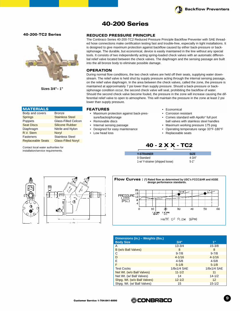
40-200-TC2 Series REDUCED PRESSURE PRINCIPLEThe Conbraco Series 40-200-TC2 Reduced Pressure Principle Backflow Preventer with SAE thread-ed hose connections make certification testing fast and trouble-free, especially in tight installations. Itis designed to give maximum protection against backflow caused by either back-pressure or back-siphonage. The durable, but economical, device is easily maintained in the line without any specialtools. It consists of two independently acting spring-loaded check valves with an automatic differen-tial relief valve located between the check valves. The diaphragm and the sensing passage are builtinto the all bronze body to eliminate possible damage.
OPERATIONDuring normal flow conditions, the two check valves are held off their seats, supplying water down-stream. The relief valve is held shut by supply pressure acting through the internal sensing passage,on the relief valve diaphragm. In the area between the check valves, called the zone, the pressure ismaintained at approximately 7 psi lower than supply pressure. Should a back-pressure or back-siphonage condition occur, the second check valve will seal, prohibiting the backflow of water.Should the second check valve become fouled, the pressure in the zone will increase causing the dif-ferential relief valve to open to atmosphere. This will maintain the pressure in the zone at least 2 psilower than supply pressure.
FEATURES• Maximum protection against back-pres-
sure/backsiphonage• Removable discs• Internal sensing passage• Designed for easy maintenance• Low head loss
• Economical• Corrosion resistant• Comes standard with Apollo® full port
ball valves with stainless steel handles• Maximum working pressure 175 psig• Operating temperature range 33°F-180°F• Replaceable seats
Dimensions (in.) – Weights (lbs.)Body Size 3/4" 1"A 13-3/4 15-3/8B (w/o Ball Valves) 8 8C 9-7/8 9-7/8D 4-1/16 4-1/16E 4-5/8 4-5/8F 5-1/8 5-1/8Test Cocks 1/8x1/4 SAE 1/8x1/4 SAENet Wt. (w/o Ball Valves) 11-1/2 11Net Wt. (w/ Ball Valves) 14 14-1/2Shpg. Wt. (w/o Ball Valves) 12-1/2 12Shpg. Wt. (w/ Ball Valves) 15 15-1/2
40 - 2 X X - TC2
Y-STRAINER0-Standard1-w/ Y-strainer (shipped loose)
SIZE4-3/4"5-1"
Flow Curves : (*) Rated flow as determined by USC’s FCCC&HR and ASSE design performance standards.
Sizes 3/4"– 1"
MATERIALSBody and covers BronzeSprings Stainless SteelPoppets Glass-Filled CelconSeat Discs Silicone RubberDiaphragm Nitrile and NylonR.V. Stem NorylFasteners Stainless SteelReplaceable Seats Glass-Filled Noryl
Contact local water authorities for installation/service requirements.

10
Backflow Preventers
Customer Service 1-704-841-6000
Dimensions (in.) – Weights (lbs.)Body Size 1/4" 3/8" 1/2" 3/4" 1" 1-1/4" 1-1/2" 2"A 10-3/16 10-1/4 10-3/4 13-3/4 15-3/8 17-1/2 19-1/2 21-1/2B (w/o Ball Valves) 5-3/4 5-3/4 5-3/4 8 8 11 11 11C 6-7/8 6-7/8 6-7/8 9-3/4 9-3/4 12-5/8 12-5/8 12-5/8D 2-5/8 2-5/8 2-5/8 4-1/16 4-1/16 5-3/8 5-3/8 5-3/8E 3-1/8 3-1/8 3-1/8 4-1/2 4-1/2 5-11/16 5-11/16 5-11/16F 3-3/4 3-3/4 3-3/4 5-1/8 5-1/8 7-1/8 7-1/8 7-1/8Test Cocks 1/8x1/4NPT 1/8x1/4NPT 1/8x1/4NPT 1/8x1/4NPT 1/8x1/4NPT 1/4x1/4NPT 1/4x1/4NPT 1/4x1/4NPTNet Wt. (w/o Ball Valves) 5.7 5.7 5.1 11-1/2 11 30-1/2 27-1/2 27Net Wt. (w/ Ball Valves) 7 7 7.4 14 14-1/2 35-1/2 37 39-1/2Shpg. Wt. (w/o Ball Valves) 6.6 6.6 6 12-1/2 12 32-1/2 29 29Shpg. Wt. (w/ Ball Valves) 7.9 7.9 8.3 15 15-1/2 38 39 41
40-200-T2 Series REDUCED PRESSURE PRINCIPLEThe Conbraco Series 40-200-T2 Reduced Pressure Principle Backflow Preventer is designed togive maximum protection against backflow caused by either back-pressure or back-siphonage. Thedurable, but economical, device is easily maintained in the line without any special tools. It consistsof two independently acting spring-loaded check valves with an automatic differential relief valvelocated between the check valves. The diaphragm and the sensing passage are built into the allbronze body to eliminate possible damage. Three of the testcocks are mounted at the top to assureeasy access during repair and maintenance when unit is installed in tight places.
OPERATIONDuring normal flow conditions, the two check valves are held off their seats, supplying water downstream. The relief valve is held shut by supply pressure acting through the internal sensing passage, on the relief valve diaphragm. In the area between the check valves, called the zone, thepressure is maintained at approximately 7 psi lower than supply pressure. Should a back-pressureor back-siphonage condition occur, the second check valve will seal, prohibiting the backflow ofwater. Should the second check valve become fouled, the pressure in the zone will increase causing the differential relief valve to open to atmosphere. This will maintain the pressure in the zone at least 2 psi lower than supply pressure.
FEATURES• Maximum protection against back-pres-
sure/backsiphonage• Removable discs• Internal sensing passage• Designed for easy maintenance• Low head loss• Economical
• Corrosion resistant• Comes standard with Apollo® full port
ball valves with stainless steel handles• Maximum working pressure 175 psig• Operating temperature range 33°F-180°F• Replaceable seats
40 - 2 X X - TX
Y-STRAINER0-Standard1-w/ Y-strainer (shipped loose)
NON UL CLASSIFIED1-less ball valves2-w/ball valves4-w/union end ball valves
FOR UL CLASSIFIED (3/4"-2")
FP1-Less ball valvesFP2-w/ball valves
SIZE1-1/4"2-3/8"3-1/2"4-3/4"5-1"6-1-1/4"7-1-1/2"8-2"
Flow Curves : (*) Rated flow as determined by USC’s FCCC&HR and ASSE design performance standards.
MATERIALSBody and covers BronzeSprings Stainless SteelPoppets Glass-Filled CelconSeat Discs Silicone RubberDiaphragm Nitrile and NylonR.V. Stem NorylFasteners Stainless SteelReplaceable Seats Glass-Filled Noryl
Contact local water authorities for installation/service requirements.
Sizes 1/4", 3/8", 1/2", 3/4", 1", 1-1/4", 1-1/2", 2"
40-200 Series

11
Backflow Preventers
Customer Service 1-704-841-6000
40-200 Series
40-205-FHB Series FIRE HYDRANT BACKFLOW METERThe Conbraco Series 40-205-FHB Fire Hydrant Backflow Meter shall measure potable water from a fire hydrant or other non-permanent installation. At the same time it shall protect against backflowby either back-pressure or backsiphonage from a cross-connection between potable water systemand substances that are non-health and health hazards. The unit shall consist of a 3/4" Short WaterMeter, 1" RP device, 1" resilient-seated full port ball valve with locking device, 2 1/2"-7 1/2" NSTthreaded hose couplings, strainer on inlet of meter and adjustable support rod assembly.
OPERATION The Fire Hydrant Backflow Meter is connected directly to a fire hydrant with a 2 1/2"-7 1/2" NST firehose female swivel coupling. The device operates like a standard Reduced Pressure device exceptthe flow through the device is measured by a Water Meter connected to the inlet of the backflow preventer. Support rod assembly is adjustable to accommodate fire hydrants at different heights from the ground.
FEATURES• Normal operating flow range 2-30 gpm• Accuracy 100% ± 1.5% of actual thruput• Low flow registration 95% at 1/2 gpm• Maximum pressure loss 11.0 psi at 30 gpm• Maximum operating pressure 150 psi• Measuring element oscillating piston• Register is straight reading, hermetically
sealed magnetic drive• Meter maincase is bronze, measuring
chamber is Rocksyn, a corrosion resistantthermoplastic material, maincase bottomplate is bronze, gears are self-lubricating,molded plastic for long life and minimumfriction, magnets are Alnico, trim and casing bolts are stainless steel and straineris thermoplastic.
• Tamperproof locking system inside the meter
• 2 1/2"-7 1/2" NST fire hose swivel couplings, female inlet, male outlet
• Maximum rate listed is for intermittent flow only. Maximum continuous flow rate asspecified by AWWA is 15 gpm.
Contact local water authorities for installation/service requirements.
Size 1"
Model Number40-205-FHB (meter in cu. ft.)40-205-FHBG (meter in gallons)
DIMENSIONS (in.)—WEIGHTS (lbs.)NET WEIGHT 24.1SHIPPING WEIGHT 27.6
12
Backflow Preventers
Customer Service 1-704-841-6000
40-200 Series
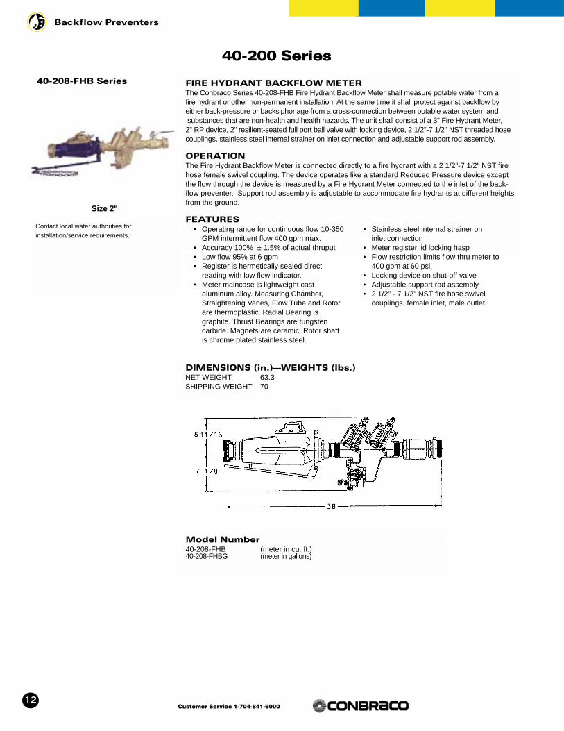
40-208-FHB Series FIRE HYDRANT BACKFLOW METERThe Conbraco Series 40-208-FHB Fire Hydrant Backflow Meter shall measure potable water from a fire hydrant or other non-permanent installation. At the same time it shall protect against backflow byeither back-pressure or backsiphonage from a cross-connection between potable water system andsubstances that are non-health and health hazards. The unit shall consist of a 3" Fire Hydrant Meter, 2" RP device, 2" resilient-seated full port ball valve with locking device, 2 1/2"-7 1/2" NST threaded hosecouplings, stainless steel internal strainer on inlet connection and adjustable support rod assembly.
OPERATION The Fire Hydrant Backflow Meter is connected directly to a fire hydrant with a 2 1/2"-7 1/2" NST firehose female swivel coupling. The device operates like a standard Reduced Pressure device exceptthe flow through the device is measured by a Fire Hydrant Meter connected to the inlet of the back-flow preventer. Support rod assembly is adjustable to accommodate fire hydrants at different heightsfrom the ground.
FEATURES• Operating range for continuous flow 10-350
GPM intermittent flow 400 gpm max.• Accuracy 100% ± 1.5% of actual thruput• Low flow 95% at 6 gpm• Register is hermetically sealed direct
reading with low flow indicator.• Meter maincase is lightweight cast
aluminum alloy. Measuring Chamber,Straightening Vanes, Flow Tube and Rotorare thermoplastic. Radial Bearing isgraphite. Thrust Bearings are tungsten carbide. Magnets are ceramic. Rotor shaftis chrome plated stainless steel.
• Stainless steel internal strainer on inlet connection
• Meter register lid locking hasp• Flow restriction limits flow thru meter to
400 gpm at 60 psi.• Locking device on shut-off valve• Adjustable support rod assembly• 2 1/2" - 7 1/2" NST fire hose swivel
couplings, female inlet, male outlet.
Contact local water authorities for installation/service requirements.
Size 2"
Model Number40-208-FHB (meter in cu. ft.)40-208-FHBG (meter in gallons)
DIMENSIONS (in.)—WEIGHTS (lbs.)NET WEIGHT 63.3SHIPPING WEIGHT 70

13
Backflow Preventers
Customer Service 1-704-841-6000
40-200-T2S Series STAINLESS STEEL T2S REDUCED PRESSURE PRINCIPLEBACKFLOW PREVENTERThe Conbraco Series 40-200-T2S Stainless Steel Reduced Pressure Principle BackflowPreventer is designed to give maximum protection against backflow caused by either back-pressure or back-siphonage from a cross-connection wherein a contaminant hazard exists (i.e. a health hazard), or a pollutant hazard exists (i.e. a non-hazard). The assembly is composed of two spring-loaded poppet type check valves and a mechanically independent, hydraulicallydependent pressure differential relief valve set in an integral stainless steel body. Three of thetestcocks are mounted at the top to assure easy access during repair and maintenance whenunit is installed in tight places.
OPERATIONDuring normal flow conditions, the two check valves are held off their seats, supplying waterdownstream. The relief valve is held shut by supply pressure acting through the internal sensingpassage, on the relief valve diaphragm. In the area between the check valves, called the zone,the pressure is maintained at approximately 7 psi lower than supply pressure. Should a back-pressure or back-siphonage condition occur, the second check valve will seal, prohibiting thebackflow of water. Should the second check valve become fouled, the pressure in the zone will increase causing the differential relief valve to open to atmosphere. This will maintain thepressure in the zone at least 2 psi lower than supply pressure.
FEATURES• Stainless steel body and covers• Easy to install and repair• Internal sensing passage• Low head loss• Removable seat discs
• Replaceable seats• Comes standard with Apollo® stainless steel full
port ball valves with stainless steel handles• Maximum working pressure 175 psig• Temperature range 33°F-180°F
Dimensions (in.) – Weights (lbs.)Body Size 1/4" 3/8" 1/2" 3/4" 1"A 10-1/2 10-1/2 10-1/2 13-1/2 15-1/4B 5-3/4 5-3/4 5-3/4 7-15/16 7-15/16C 6-7/8 6-7/8 6-7/8 9 9D 2-5/8 2-5/8 2-5/8 4-1/16 4-1/16E 3-3/16 3-3/16 3-3/16 4-3/8 4-3/8F 3-3/4 3-3/4 3-3/4 5-1/8 5-1/8Test Cocks 1/8 x 1/4NPT 1/8 x 1/4NPT 1/8 x 1/4NPT 1/8 x 1/4NPT 1/8 x 1/4NPTNet Wt. (w/o Ball Valves) 4-1/4 4-1/4 4-1/8 8-1/4 8-1/8Net Wt. (with Ball Valves) 5-1/2 5-1/2 5-3/8 10-3/4 11Shpg. Wt. (w/o Ball Valves) 5-1/8 5-1/8 5 9-3/4 9-5/8Shpg. Wt. (with Ball Valves)6-3/8 6-3/8 6-1/4 12-1/4 12-3/4
40 - 20 X - T2S
FOR UL CLASSIFIED (3/4" AND 1")
FP1S-less ball valvesFP2S-w/ball valves
SIZE1-1/4"2-3/8"3-1/2"4-3/4"5-1"
Flow Curves : (*) Rated flow as determined by USC’s FCCC&HR and ASSE design performance standards.
MATERIALSBody and Cover Stainless SteelSprings Stainless SteelFasteners Stainless SteelPoppets Glass-Filled CelconSeat Discs Silicone RubberDiaphragm FDA Fluorocarbonand O-RingsReplaceable Seats Glass-Filled Noryl
Contact local water authorities for installation/service requirements.
Sizes 1/4", 3/8", 1/2", 3/4", 1"
40-200 Series

14
Backflow Preventers
Customer Service 1-704-841-6000
40-200-TCU Series TCU U FLOW REDUCED PRESSURE PRINCIPLEThe Conbraco Series 40-200-TCU Reduced Pressure Principle Backflow Preventer with SAEthreaded hose connections make certification testing fast and trouble-free, especially in tightinstallations. It is designed to give maximum protection against backflow caused by either back-pressure or back-siphonage. The durable, but economical, device is easily maintained in the linewithout any special tools. It consists of two independently acting spring-loaded check valves withan automatic differential relief valve located between the check valves. The diaphragm and thesensing passage are built into the all bronze body to eliminate possible damage. The assemblyoffers installation flexibility by providing inlet and outlet bronze elbows to meet space require-ments, adaptability and lower installation cost.
OPERATIONDuring normal flow conditions, the two check valves are held off their seats, supplying water down-stream. The relief valve is held shut by supply pressure acting through the internal sensing passage,on the relief valve diaphragm. In the area between the check valves, called the zone, the pressure ismaintained at approximately 7 psi lower than supply pressure. Should a back-pressure or back-siphonage condition occur, the second check valve will seal, prohibiting the backflow of water.Should the second check valve become fouled, the pressure in the zone will increase causing the dif-ferential relief valve to open to atmosphere. This will maintain the pressure in the zone at least 2 psilower than supply pressure.
FEATURES
• Maximum protection against back-pressure/back-siphonage
• Designed for easy maintenance• Low installation cost• Compact• Internal sensing passage• Low head loss
• Removable seat discs• Replaceable seats• Comes standard with Apollo® full port
ball valves with stainless steel handles• Maximum working pressure 175 psig• Temperature range 33°F-180°F
Dimensions (in.) – Weights (lbs.)Body Size 3/4" 1"A 10-1/2 10-11/16B 8 8C 4-1/8 5-3/16D 4-7/16 4-9/16E 13-7/8 15-1/8F 4-1/2 4-1/2G 5-1/8 5-1/8Test Cocks 1/8 x 1/4 SAE 1/8 x 1/4 SAENet Wt. (with Ball Valves) 14.7 15.6Shipping Wt. (with Ball Valves) 15.7 16.6
40 - 2 0 X - TCU
SIZES4-3/4"5-1"
Flow Curves : (*) Rated flow as determined by USC’s FCCC&HR and ASSE design performance standards.
MATERIALSBody, covers & elbowsBronzeSprings Stainless SteelPoppets Glass-Filled CelconSeat Discs Silicone RubberDiaphragm Nitrile and NylonR.V. Stem NorylFasteners Stainless SteelReplaceable Seats Glass-Filled Noryl
Contact local water authorities for installation/service requirements.
Sizes 3/4", 1"
40-200 Series
15
Backflow Preventers
Customer Service 1-704-841-6000
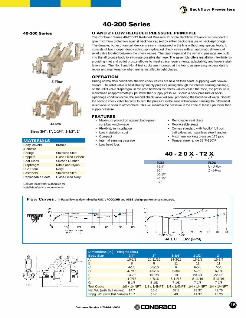
Sizes 3/4", 1", 1-1/4", 1-1/2", 2"
40-200 Series40-200 Series U AND Z FLOW REDUCED PRESSURE PRINCIPLE
The Conbraco Series 40-200-T2 Reduced Pressure Principle Backflow Preventer is designed togive maximum protection against backflow caused by either back-pressure or back-siphonage.The durable, but economical, device is easily maintained in the line without any special tools. Itconsists of two independently acting spring-loaded check valves with an automatic differentialrelief valve located between the check valves. The diaphragm and the sensing passage are builtinto the all bronze body to eliminate possible damage. The assembly offers installation flexibility byproviding inlet and outlet bronze elbows to meet space requirements, adaptability and lower instal-lation cost. The No. 3 and No. 4 test cocks are mounted at the top to assure easy access duringrepair and maintenance when unit is installed in tight places.
OPERATIONDuring normal flow conditions, the two check valves are held off their seats, supplying water down-stream. The relief valve is held shut by supply pressure acting through the internal sensing passage,on the relief valve diaphragm. In the area between the check valves, called the zone, the pressure ismaintained at approximately 7 psi lower than supply pressure. Should a back-pressure or back-siphonage condition occur, the second check valve will seal, prohibiting the backflow of water. Shouldthe second check valve become fouled, the pressure in the zone will increase causing the differentialrelief valve to open to atmosphere. This will maintain the pressure in the zone at least 2 psi lower thansupply pressure.
FEATURES• Maximum protection against back-pres-
sure/back-siphonage• Flexibility in installation• Low installation cost• Compact• Internal sensing passage• Low head loss
• Removable seat discs• Replaceable seats• Comes standard with Apollo® full port
ball valves with stainless steel handles• Maximum working pressure 175 psig• Temperature range 33°F-180°F
40 - 2 0 X - T2 X
SIZES4-3/4"5-1"6-1-1/4"7-1-1/2"8-2"
Flow Curves : (*) Rated flow as determined by USC’s FCCC&HR and ASSE design performance standards.
MATERIALSBody, covers Bronze& elbowsSprings Stainless SteelPoppets Glass-Filled CelconSeat Discs Silicone RubberDiaphragm Nitrile and NylonR.V. Stem NorylFasteners Stainless SteelReplaceable Seats Glass-Filled Noryl
Contact local water authorities for installation/service requirements.
Z-Flow
U-Flow
FLOWU - U-FlowZ - Z-Flow
Dimensions (in.) – Weights (lbs.)Body Size 3/4" 1" 1-1/4" 1-1/2" 2"A 10-1/2 10-11/16 14-3/16 15-1/8 15-3/4B 8 8 11 11 11C 4-1/8 5-3/16 6 6-5/8 7-5/8D 4-7/16 4-9/16 5-3/4 5-7/8 6-1/4E 13-7/8 15-1/8 19 20-3/4 22-1/8F 4-7/16 4-7/16 5-11/16 5-11/16 5-11/16G 5-1/8 5-1/8 7-1/8 7-1/8 7-1/8Test Cocks 1/8 x 1/4NPT 1/8 x 1/4NPT 1/4 x 1/4NPT 1/4 x 1/4NPT 1/4 x 1/4NPTNet Wt. (with Ball Valves) 14.7 15.6 37.5 39.37 43.75Shpg. Wt. (with Ball Valves) 15.7 16.6 40 41.37 45.25

16
Backflow Preventers
Customer Service 1-704-841-6000
Flow Curves : (*) Rated flow as determined by USC’s FCCC&HR and ASSE design performance standards.
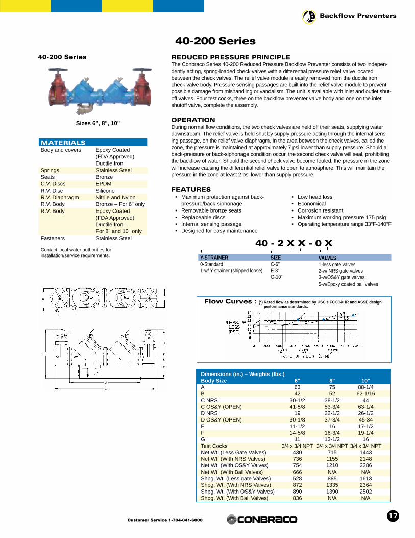
40-200 Series REDUCED PRESSURE PRINCIPLEThe Conbraco Series 40-200 Reduced Pressure Backflow Preventer consists of two independently acting, spring-loaded check valves with a differential pressure relief valve locat-ed between the check valves. The all bronze relief valve module is easily removed from theductile iron check valve body. Pressure sensing passages are built into the bronze relief valvemodule to prevent possible damage from mishandling or vandalism. The unit is available withinlet and outlet shutoff valves. Four test cocks, three on the backflow preventer valve body andone on the inlet shutoff valve, complete the assembly.
OPERATIONDuring normal flow conditions, the two check valves are held off their seats, supplying waterdownstream. The relief valve is held shut by supply pressure acting through the internal sensing passage, on the relief valve diaphragm. In the area between the check valves, calledthe zone, the pressure is maintained at approximately 7 psi lower than supply pressure.Should a back-pressure or back-siphonage condition occur, the second check valve will seal, prohibiting the backflow of water. Should the second check valve become fouled, thepressure in the zone will increase causing the differential relief valve to open to atmosphere.This will maintain the pressure in the zone at least 2 psi lower than supply pressure.
FEATURES• Maximum protection against back-pres-
sure/back-siphonage• Removable bronze seats• Replaceable discs• Internal sensing passage• Designed for easy maintenance
• Low head loss• Economical• Corrosion resistant• Maximum working pressure 175 psig• Operating temperature range 33°F 140°F
40 - 2 X X - 0 X
Y-STRAINER0-Standard1-w/ Y-strainer (shipped loose)
SIZE9-2-1/2"0-3"A-4"
VALVES1-less gate valves2-w/ NRS gate valves3-w/OS&Y gate valves5-w/Epoxy coated ball valves
MATERIALS
Body and cover Epoxy Coated (FDA Approved)Ductile Iron
Springs Stainless SteelSeats BronzeC.V. Discs EPDMR.V. Disc SiliconeR.V. Diaphragm Nitrile and NylonR.V. Body BronzeFasteners Stainless Steel
Contact local water authorities for installation/service requirements.
Sizes 2-1/2", 3", 4"
Dimensions (in.) – Weights (lbs.)Body Size 2-1/2" 3" 4"A 37-1/16 38-1/16 46-3/4B 22-1/16 22-1/16 28-1/2C NRS 20-7/8 21-7/8 25-3/16C OS&Y (OPEN) 25-7/8 28-3/8 33-3/16D NRS 11-3/8 12-3/8 14-3/4D OS&Y (OPEN) 16-3/8 18-7/8 22-3/4E 9-1/2 9-1/2 10-7/16F 9-5/8 10-3/8 11-7/8G 7 7-1/2 9Test Cocks 1/2 x 1/2 NPT 1/2 x 1/2 NPT 1/2 x 1/2 NPTNet Wt. (Less Gate Valves) 120 122 196Net Wt. (With NRS Valves) 219 252 388Net Wt. (With OS&Y Valves) 229 259 402Net Wt. (With Ball Valves) 188 198 312Shpg. Wt. (Less gate Valves) 184 186 260Shpg. Wt. (With NRS Valves) 283 316 452Shpg. Wt. (With OS&Y Valves) 293 323 466Shpg. Wt. (With Ball Valves) 252 262 376
40-200 Series
17
Backflow Preventers
Customer Service 1-704-841-6000
Flow Curves : (*) Rated flow as determined by USC’s FCCC&HR and ASSE design performance standards.
40-200 Series REDUCED PRESSURE PRINCIPLEThe Conbraco Series 40-200 Reduced Pressure Backflow Preventer consists of two indepen-dently acting, spring-loaded check valves with a differential pressure relief valve locatedbetween the check valves. The relief valve module is easily removed from the ductile ironcheck valve body. Pressure sensing passages are built into the relief valve module to preventpossible damage from mishandling or vandalism. The unit is available with inlet and outlet shut-off valves. Four test cocks, three on the backflow preventer valve body and one on the inletshutoff valve, complete the assembly.
OPERATIONDuring normal flow conditions, the two check valves are held off their seats, supplying waterdownstream. The relief valve is held shut by supply pressure acting through the internal sens-ing passage, on the relief valve diaphragm. In the area between the check valves, called thezone, the pressure is maintained at approximately 7 psi lower than supply pressure. Should aback-pressure or back-siphonage condition occur, the second check valve will seal, prohibitingthe backflow of water. Should the second check valve become fouled, the pressure in the zone will increase causing the differential relief valve to open to atmosphere. This will maintain thepressure in the zone at least 2 psi lower than supply pressure.
FEATURES• Maximum protection against back-
pressure/back-siphonage• Removable bronze seats• Replaceable discs• Internal sensing passage• Designed for easy maintenance
• Low head loss• Economical• Corrosion resistant• Maximum working pressure 175 psig• Operating temperature range 33°F-140°F
40 - 2 X X - 0 X
Y-STRAINER0-Standard1-w/ Y-strainer (shipped loose)
SIZEC-6"E-8"G-10"
VALVES1-less gate valves2-w/ NRS gate valves3-w/OS&Y gate valves5-w/Epoxy coated ball valves
MATERIALSBody and covers Epoxy Coated
(FDA Approved)Ductile Iron
Springs Stainless SteelSeats BronzeC.V. Discs EPDMR.V. Disc SiliconeR.V. Diaphragm Nitrile and NylonR.V. Body Bronze – For 6" onlyR.V. Body Epoxy Coated
(FDA Approved)Ductile Iron – For 8" and 10" only
Fasteners Stainless Steel
Contact local water authorities for installation/service requirements.
Sizes 6", 8", 10"
Dimensions (in.) – Weights (lbs.)Body Size 6" 8" 10"A 63 75 88-1/4B 42 52 62-1/16C NRS 30-1/2 38-1/2 44C OS&Y (OPEN) 41-5/8 53-3/4 63-1/4D NRS 19 22-1/2 26-1/2D OS&Y (OPEN) 30-1/8 37-3/4 45-34E 11-1/2 16 17-1/2F 14-5/8 16-3/4 19-1/4G 11 13-1/2 16Test Cocks 3/4 x 3/4 NPT 3/4 x 3/4 NPT 3/4 x 3/4 NPTNet Wt. (Less Gate Valves) 430 715 1443Net Wt. (With NRS Valves) 736 1155 2148Net Wt. (With OS&Y Valves) 754 1210 2286Net Wt. (With Ball Valves) 666 N/A N/AShpg. Wt. (Less gate Valves) 528 885 1613Shpg. Wt. (With NRS Valves) 872 1335 2364Shpg. Wt. (With OS&Y Valves) 890 1390 2502Shpg. Wt. (With Ball Valves) 836 N/A N/A
40-200 Series
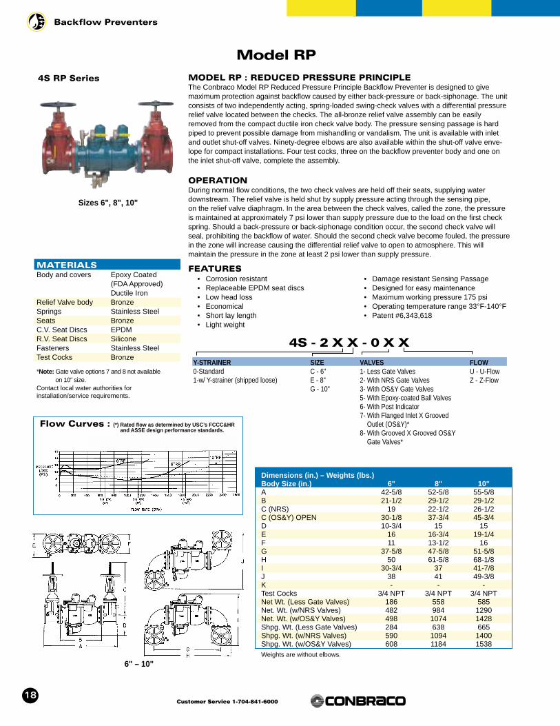
Dimensions (in.) – Weights (lbs.)Body Size (in.) 6" 8" 10"A 42-5/8 52-5/8 55-5/8B 21-1/2 29-1/2 29-1/2C (NRS) 19 22-1/2 26-1/2C (OS&Y) OPEN 30-1/8 37-3/4 45-3/4D 10-3/4 15 15E 16 16-3/4 19-1/4F 11 13-1/2 16G 37-5/8 47-5/8 51-5/8H 50 61-5/8 68-1/8I 30-3/4 37 41-7/8J 38 41 49-3/8K - - -Test Cocks 3/4 NPT 3/4 NPT 3/4 NPTNet Wt. (Less Gate Valves) 186 558 585Net. Wt. (w/NRS Valves) 482 984 1290Net. Wt. (w/OS&Y Valves) 498 1074 1428Shpg. Wt. (Less Gate Valves) 284 638 665Shpg. Wt. (w/NRS Valves) 590 1094 1400Shpg. Wt. (w/OS&Y Valves) 608 1184 1538Weights are without elbows.
6" – 10"
Model RP
4S RP Series
• Corrosion resistant• Replaceable EPDM seat discs• Low head loss• Economical• Short lay length• Light weight
• Damage resistant Sensing Passage• Designed for easy maintenance• Maximum working pressure 175 psi• Operating temperature range 33°F-140°F• Patent #6,343,618
4S - 2 X X - 0 X X
Y-STRAINER0-Standard1-w/ Y-strainer (shipped loose)
SIZEC - 6"E - 8"G - 10"
FLOWU - U-FlowZ - Z-Flow
VALVES1- Less Gate Valves2- With NRS Gate Valves3- With OS&Y Gate Valves5- With Epoxy-coated Ball Valves6- With Post Indicator7- With Flanged Inlet X Grooved
Outlet (OS&Y)*8- With Grooved X Grooved OS&Y
Gate Valves*
MATERIALSBody and covers Epoxy Coated
(FDA Approved)Ductile Iron
Relief Valve body BronzeSprings Stainless SteelSeats BronzeC.V. Seat Discs EPDMR.V. Seat Discs SiliconeFasteners Stainless SteelTest Cocks Bronze
*Note: Gate valve options 7 and 8 not available on 10" size.
Contact local water authorities for installation/service requirements.
Sizes 6", 8", 10"
18
Backflow Preventers
Customer Service 1-704-841-6000
Flow Curves : (*) Rated flow as determined by USC’s FCCC&HRand ASSE design performance standards.
MODEL RP : REDUCED PRESSURE PRINCIPLEThe Conbraco Model RP Reduced Pressure Principle Backflow Preventer is designed to give maximum protection against backflow caused by either back-pressure or back-siphonage. The unitconsists of two independently acting, spring-loaded swing-check valves with a differential pressurerelief valve located between the checks. The all-bronze relief valve assembly can be easilyremoved from the compact ductile iron check valve body. The pressure sensing passage is hardpiped to prevent possible damage from mishandling or vandalism. The unit is available with inletand outlet shut-off valves. Ninety-degree elbows are also available within the shut-off valve enve-lope for compact installations. Four test cocks, three on the backflow preventer body and one onthe inlet shut-off valve, complete the assembly.
OPERATIONDuring normal flow conditions, the two check valves are held off their seats, supplying water downstream. The relief valve is held shut by supply pressure acting through the sensing pipe, on the relief valve diaphragm. In the area between the check valves, called the zone, the pressureis maintained at approximately 7 psi lower than supply pressure due to the load on the first checkspring. Should a back-pressure or back-siphonage condition occur, the second check valve willseal, prohibiting the backflow of water. Should the second check valve become fouled, the pressurein the zone will increase causing the differential relief valve to open to atmosphere. This will maintain the pressure in the zone at least 2 psi lower than supply pressure.
FEATURES

19
Backflow Preventers
Customer Service 1-704-841-6000
Dimensions (in.) – Weights (lbs.)Size 1/2" 3/4" 1"A 4-3/8 4-3/8 4-3/8B 3-1/2 3-1/2 3-1/2C 1-1/2 1-1/2 1-1/2D 1-11/16 1-11/16 1-11/16Test Port Size 1/8" NPT 1/8" NPT 1/8" NPTUnit Wt. (with plugs) 2 2 2.1Unit Wt. (with test cocks) 2.4 2.4 2.5Unit Wt. (with T.C.’s & Ball Valves) 4 4.6 6.4Unit Wt. (with T.C.’s & Outlet Ball Valve) 3.2 3.4 4.4
40 - 3 X X - X X X
INLET CONNECTIONA – FNPTB – MNPTC – Female Meter Thread*E – Male Meter Thread*S – Female Meter Thread (Swivel)*2 – Female BSPP
INLET AND OUTLET SIZE3 – 1/2"4 – 3/4"5 – 1"
OUTLET CONNECTIONA – FNPTB – MNPTC – Female Meter ThreadE – Male Meter ThreadF – Female BSPP
TEST COCKS1 – With Test Cocks2 – With Test Cocks
& Ball Valves3 – With Test Cocks
& Outlet Ball Valve4 – With 4 Test Cocks
& Inlet & Outlet Ball Valves
Flow Curves : (*) Rated flow as determined by USC’s FCCC&HR and ASSEdesign performance standards.
40-300 Series
40-300 Series DUAL CHECK VALVEThe Conbraco Series 40-300 Dual Check Valve Backflow Preventer is designed to prevent cross-connections of non-potable water (non-hazardous) into the safe drinking water systems. It is a compact and economical device that is easily installed, serviced and repaired in the line. Thedevice consists of two independently acting, spring-loaded check valves in a corrosion resistantmaterial. It is equipped with three (3) 1/8" NPT test ports for ease of field testing while the valve isin the line.
OPERATIONEach of the two spring-loaded check valves is designed to open at 1 psi differential in the directionof flow. They will remain tightly closed until there is a demand of water downstream. If the down-stream pressure of the device increases above the supply pressure or there is a reverse directionof flow, the check valves will close to prevent backflow. If the second check valve is prevented fromclosing tightly, the first check valve will still provide protection from a backflow condition.
FEATURES• In-line repairable• In-line testable• Low head loss• Independently acting check valves• Compact and lightweight• Ease of repair and installation
• Corrosion resistant• Almost any inlet and outlet connection
combination to fit your needs• Maximum working pressure 175 psig• Operating temperature range 33°F-180°F
MATERIALSBody and covers BronzeSprings Stainless SteelSeat Discs EPDMPoppet Celcon
Contact local water authorities for installation/service requirements.
Sizes 1/2", 3/4", 1"
* On meter threads order one size larger than meter size.
TYPICAL INSTALLATION

20
Backflow Preventers
Customer Service 1-704-841-6000
Flow Curves : (*) Rated flow as determined by USC’s FCCC&HR and ASSE design performance standards.
Model CBBP
4C-100 Series CARBONATED BEVERAGE BACKFLOW PREVENTERThe Conbraco 4C-100 Series Carbonated Beverage Backflow Preventer (CBBP) is designed toprevent the contamination of the potable water supply due to backflow when installed on water distribution lines serving beverage dispensing equipment. The device consists of two independentlyacting check valves biased to a normally closed position. A normally open atmospheric port is locat-ed between the check valves. During backflow conditions, the port vents gases and/or liquids.Additionally, the CBBP is equipped with a 100 mesh integral strainer screen at the inlet. All wettedareas of the device are non-toxic, corrosion resistant, and approved for use with potable water. TheCBBP is suitable for supply pressures to 150 psig and water temperatures from 33˚ to 130˚ F.
OPERATIONUnder static (non-flowing) conditions, the check valves remain in the closed position. When a valveis opened downstream (i.e. a drink is delivered from the beverage dispensing unit), the checkvalves open and permit the flow of water. Under backflow conditions, the diaphragm seat on thefirst check lifts and permits flow through the atmospheric port located between the two checkvalves. The strainer insures debris does not enter the carbonator.
FEATURES
• Compact Design• Lowest head loss• Atmospheric vent provides indication
of problems• Integral strainer for equipment protection
• NSF-18 listed• Repairable check assemblies• Non-metallic body for corrosion resistance• CSA Certified to ANSI/NSF-61
4C - 1 0 X - 0 1
SIZE1 – 1/4"2 – 3/8"
MATERIALSEnd cap AcetalStrainer PVC/Stainless
SteelO-ring NitrileDownstream Nitrile/Stainless Check Valve Steel/AcetalUpstream Check EPDM/StainlessValve Body Acetal
Contact local water authorities for installation/service requirements.
DIMENSIONS (IN.)
Sizes 1/4", 3/8"

21
Backflow Preventers
Customer Service 1-704-841-6000
4W - 5 0 X - 0 2
SIZE1 – 1/4"2 – 3/8"3 – 1/2"
Dimensions (in.) – Weights (lbs.)Size 1/4" 3/8" 1/2"Test Cock 1/4" Flare 1/4" Flare 1/4" FlareNet Wt. 1.16 1.16 1.16Shipping Wt. 1.26 1.26 1.26
Flow Curves : (*) Rated flow as determined by USC’s FCCC&HR and ASSE design performance standards.
Model SVB
4W-500 Series SPILL RESISTANT VACUUM BREAKERSThe Conbraco Series 4W-500 Spill Resistant Vacuum Breaker (SVB) is designed to prevent conta-mination of the potable water supply due to back-siphonage. The SVB is ideally suited for continu-ous pressure, indoor applications where water spillage is undesirable. The device has a straightthrough flow path for minimal head loss. All components are easily accessible for easy repair andmaintenance. All components are made of corrosion resistant materials for years of reliable service.
OPERATIONDuring normal flow conditions, the check valve remains open and the atmospheric vent seals in thebonnet assembly. As the line pressure falls to 1 psi, the spring loaded atmospheric vent opens andthe check valve closes, breaking the vacuum and thereby preventing back-siphonage. Water is notallowed to spill at any time during operation.
FEATURES• Corrosion Resistant• In-Line Flow• Integral Shut-Off Valves• Designed For Easy Maintenance• Low Head Loss
• Economical• Maximum Working Pressure 150 PSIG• Operating Temperature Range 33˚F-180˚F
MATERIALSBody Noryl®
Springs Stainless SteelSeat Discs Silicone RubberValve Canopy ABS PlasticFloat AcetalFasteners Stainless Steel
Contact local water authorities for installation/service requirements.
Sizes 1/4", 3/8", 1/2"
22
Backflow Preventers
Customer Service 1-704-841-6000
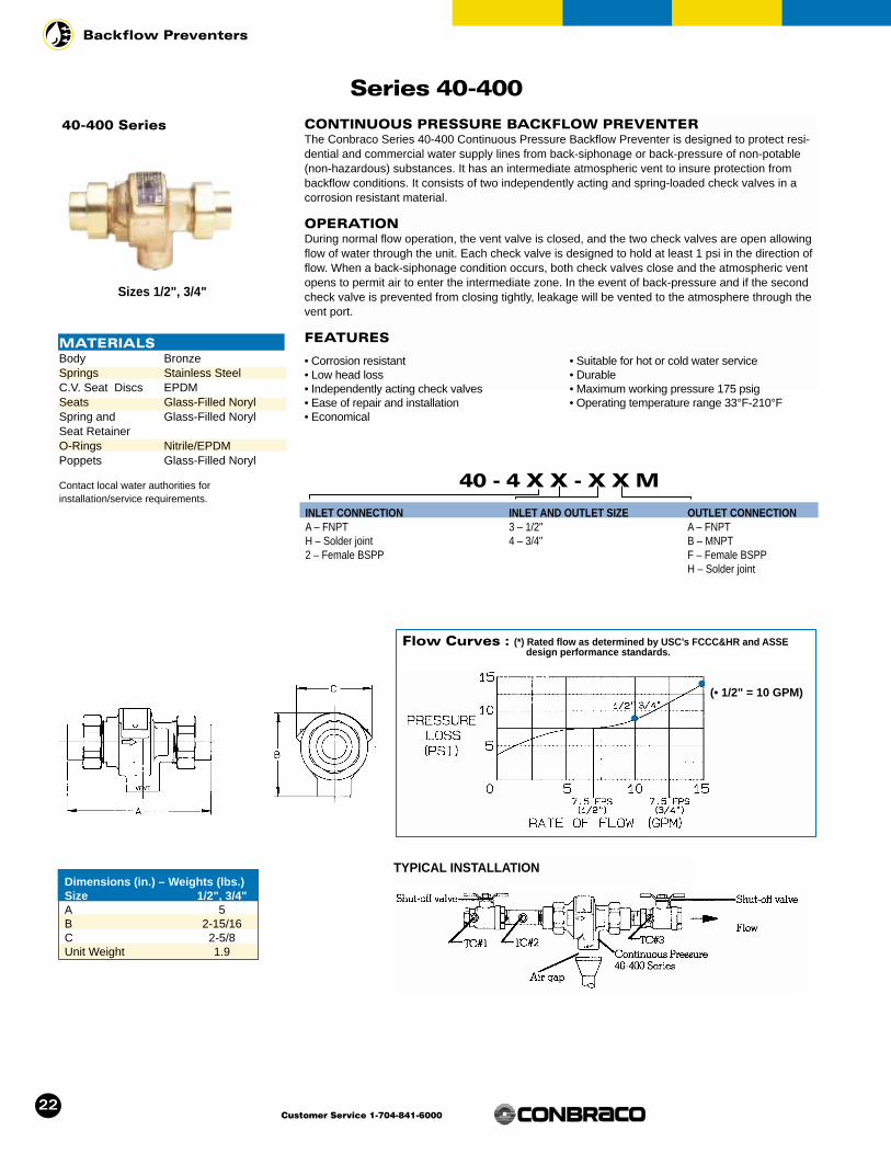
Dimensions (in.) – Weights (lbs.)Size 1/2", 3/4"A 5B 2-15/16C 2-5/8Unit Weight 1.9
Flow Curves : (*) Rated flow as determined by USC’s FCCC&HR and ASSE design performance standards.
Series 40-400
40-400 Series CONTINUOUS PRESSURE BACKFLOW PREVENTERThe Conbraco Series 40-400 Continuous Pressure Backflow Preventer is designed to protect resi-dential and commercial water supply lines from back-siphonage or back-pressure of non-potable(non-hazardous) substances. It has an intermediate atmospheric vent to insure protection frombackflow conditions. It consists of two independently acting and spring-loaded check valves in acorrosion resistant material.
OPERATIONDuring normal flow operation, the vent valve is closed, and the two check valves are open allowingflow of water through the unit. Each check valve is designed to hold at least 1 psi in the direction offlow. When a back-siphonage condition occurs, both check valves close and the atmospheric ventopens to permit air to enter the intermediate zone. In the event of back-pressure and if the secondcheck valve is prevented from closing tightly, leakage will be vented to the atmosphere through thevent port.
FEATURES
• Corrosion resistant• Low head loss• Independently acting check valves• Ease of repair and installation• Economical
• Suitable for hot or cold water service• Durable• Maximum working pressure 175 psig• Operating temperature range 33°F-210°F
40 - 4 X X - X X M
INLET CONNECTIONA – FNPTH – Solder joint2 – Female BSPP
INLET AND OUTLET SIZE3 – 1/2"4 – 3/4"
OUTLET CONNECTIONA – FNPTB – MNPTF – Female BSPPH – Solder joint
(• 1/2" = 10 GPM)
Sizes 1/2", 3/4"
MATERIALSBody BronzeSprings Stainless SteelC.V. Seat Discs EPDMSeats Glass-Filled NorylSpring and Glass-Filled NorylSeat RetainerO-Rings Nitrile/EPDMPoppets Glass-Filled Noryl
Contact local water authorities for installation/service requirements.
TYPICAL INSTALLATION

23
Backflow Preventers
Customer Service 1-704-841-6000
Model PVB
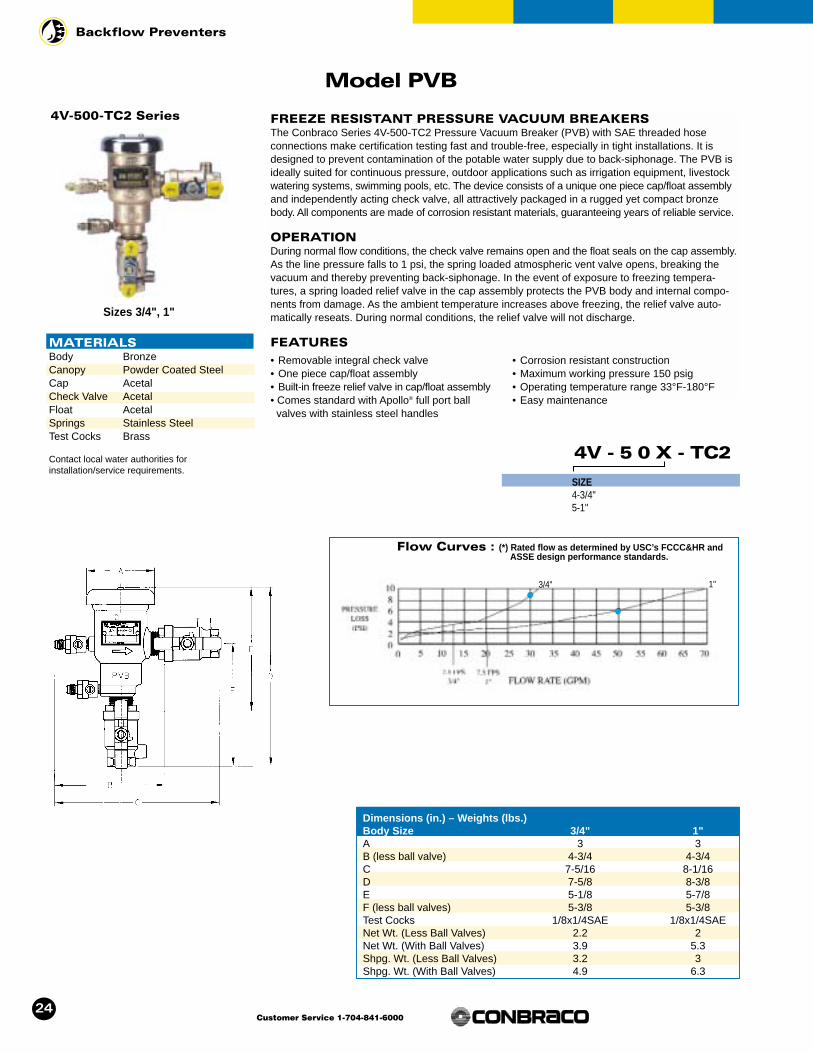
Dimensions (in.) – Weights (lbs.)Body Size 1/2" 3/4" 1" 1-1/4" 1-1/2" 2"A 3 3 3 3-3/4 3-3/4 5-1/4B (Less Ball Valves) 4-3/4 4-3/4 4-3/4 5-3/8 5-3/8 6-5/8C 6-3/8 7-1/8 7-1/2 8-3/4 9-1/4 10-1/4D 7-1/8 7-5/8 8-3/8 10-5/8 10-7/8 12-1/8E 4-5/8 5-1/8 5-7/8 7-3/8 7-3/8 7-1/8F (Less Ball Valves) 5-3/8 5-3/8 5-3/8 6-7/8 7-1/4 8-5/8Test Cocks 1/8 x 1/4 NPT 1/8 x 1/4 NPT1/8 x 1/4 NPT 1/4 x 1/4 NPT 1/4 x 1/4 NPT1/4 x 1/4 NPTNet Wt. (Less Ball Valves) 2.2 2.2 2.2 4.3 4.3 8.8Net. Wt. (With Ball Valves) 3.4 3.9 5.3 9.3 12.2 23.3Shipping Wt. (Less Ball Valves) 3.2 3.2 3 5.6 5.8 10.3Shipping Wt. (With Ball Valves) 4.4 4.9 6.3 10.5 13.7 24.8
4V - 5 0 X - 0 X
SIZE3-1/2"4-3/4"5-1"6-1-1/4"7-1-1/2"8-2"
BALL VALVES1-less ball valves2-w/ ball valves4-w/ union end ball valves
4V-500 Series FREEZE RESISTANT PRESSURE VACUUM BREAKERThe Conbraco Series 4V-500 Pressure Vacuum Breaker (PVB) is designed to prevent contamina-tion of the potable water supply due to back-siphonage. The PVB is ideally suited for continuouspressure, outdoor applications such as irrigation equipment, livestock watering systems, swimmingpools, etc. The device consists of a unique one piece cap/float assembly and independently actingcheck valve, all attractively packaged in a rugged yet compact bronze body. All components aremade of corrosion resistant materials, guaranteeing years of reliable service.
OPERATIONDuring normal flow conditions, the check valve remains open and the float seals on the cap assem-bly. As the line pressure falls to 1 psi, the spring loaded atmospheric vent valve opens, breaking thevacuum and thereby preventing back-siphonage. In the event of exposure to freezing tempera-tures, a spring loaded relief valve in the cap assembly protects the PVB body and internal compo-nents from damage. As the ambient temperature increases above freezing, the relief valve auto-matically reseats. During normal conditions, the relief valve will not discharge.
FEATURES• Removable integral check valve• One piece cap/float assembly• Built-in freeze relief valve in cap/float assembly• Corrosion resistant construction
• Comes standard with Apollo® full port ballvalves with stainless steel handles
• Maximum working pressure 150 psig• Operating temperature range 33°F-180°F• Easy maintenance
MATERIALSBody BronzeCanopy Powder Coated SteelCap AcetalCheck Valve AcetalFloat AcetalSprings Stainless SteelTest Cocks Brass
Contact local water authorities for installation/service requirements.
Sizes 1/2", 3/4", 1", 1-1/4",1-1/2", 2"
Flow Curves : (*) Rated flow as determined by USC’s FCCC&HR and ASSE design performance standards.
4V-500-TC2 Series FREEZE RESISTANT PRESSURE VACUUM BREAKERSThe Conbraco Series 4V-500-TC2 Pressure Vacuum Breaker (PVB) with SAE threaded hose connections make certification testing fast and trouble-free, especially in tight installations. It isdesigned to prevent contamination of the potable water supply due to back-siphonage. The PVB isideally suited for continuous pressure, outdoor applications such as irrigation equipment, livestockwatering systems, swimming pools, etc. The device consists of a unique one piece cap/float assemblyand independently acting check valve, all attractively packaged in a rugged yet compact bronzebody. All components are made of corrosion resistant materials, guaranteeing years of reliable service.
OPERATIONDuring normal flow conditions, the check valve remains open and the float seals on the cap assembly.As the line pressure falls to 1 psi, the spring loaded atmospheric vent valve opens, breaking thevacuum and thereby preventing back-siphonage. In the event of exposure to freezing tempera-tures, a spring loaded relief valve in the cap assembly protects the PVB body and internal compo-nents from damage. As the ambient temperature increases above freezing, the relief valve auto-matically reseats. During normal conditions, the relief valve will not discharge.
FEATURES
• Removable integral check valve• One piece cap/float assembly• Built-in freeze relief valve in cap/float assembly• Comes standard with Apollo® full port ball
valves with stainless steel handles
• Corrosion resistant construction• Maximum working pressure 150 psig• Operating temperature range 33°F-180°F• Easy maintenance
Dimensions (in.) – Weights (lbs.)Body Size 3/4" 1"A 3 3B (less ball valve) 4-3/4 4-3/4C 7-5/16 8-1/16D 7-5/8 8-3/8E 5-1/8 5-7/8F (less ball valves) 5-3/8 5-3/8Test Cocks 1/8x1/4SAE 1/8x1/4SAENet Wt. (Less Ball Valves) 2.2 2Net Wt. (With Ball Valves) 3.9 5.3Shpg. Wt. (Less Ball Valves) 3.2 3Shpg. Wt. (With Ball Valves) 4.9 6.3
24
Backflow Preventers
Customer Service 1-704-841-6000
Model PVB
4V - 5 0 X - TC2
SIZE4-3/4"5-1"
MATERIALSBody BronzeCanopy Powder Coated SteelCap AcetalCheck Valve AcetalFloat AcetalSprings Stainless SteelTest Cocks Brass
Contact local water authorities for installation/service requirements.
Sizes 3/4", 1"
Flow Curves : (*) Rated flow as determined by USC’s FCCC&HR and ASSE design performance standards.
3/4" 1"
25
Backflow Preventers
Customer Service 1-704-841-6000
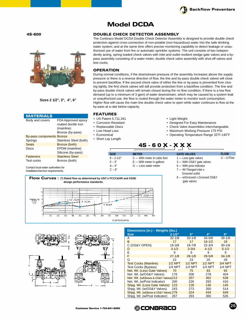
Dimensions (in.) – Weights (lbs.)Size 2-1/2" 3" 4" 6"A 32-1/8 33-1/8 34-5/8 39-1/8B 17 17 16-1/2 18C (OS&Y OPEN) 16-3/8 18-7/8 22-3/4 30-1/8D 3-1/2 3-3/4 4-1/2 5-1/2E 9 9 9 9F 27-1/8 28-1/8 29-5/8 34-1/8G 22 23 25 29Test Cocks (Mainline) 1/2 NPT 1/2 NPT 1/2 NPT 3/4 NPTTest Cocks (Bypass) 1/4 NPT 1/4 NPT 1/4 NPT 1/4 NPTNet. Wt. (Less Gate Valves) 70 75 83 92Net. Wt. (w/OS&Y Valves) 176 206 278 404Net. Wt. (w/Elbows & OS&Y Valves)212 257 362 539Net. Wt. (w/Post Indicator) 200 226 293 416Shpg. Wt. (Less Gate Valves) 123 128 136 145Shpg. Wt. (w/OS&Y Valves) 243 273 350 514Shpg. Wt. (w/Elbows & OS&Y Valves) 279 324 434 649Shpg. Wt. (w/Post Indicator) 267 293 365 526
4S-600 DOUBLE CHECK DETECTOR ASSEMBLYThe Conbraco Model DCDA Double Check Detector Assembly is designed to provide double checkprotection against cross-connection of non-potable (non-hazardous) water into the safe drinkingwater system; and at the same time offers precise monitoring capability to detect leakage or unau-thorized use of water from fire or automatic sprinkler systems. The unit consists of two indepen-dently acting, spring loaded check valves with inlet and outlet resilient wedge gate valves and a by-pass assembly consisting of a water meter, double check valve assembly with shut-off valves andtest cocks.
OPERATIONDuring normal conditions, if the downstream pressure of the assembly increases above the supplypressure or there is a reverse direction of flow, the line and by-pass double check valves will closeto prevent backflow. If the second check valve of either the line or by-pass is prevented from clos-ing tightly, the first check valves will still provide protection from a backflow condition. The line andby-pass double check valves will remain closed during the no flow condition. If there is a low flowdemand (up to a minimum of 3 gpm) of water downstream, which may be caused by a system leakor unauthorized use, the flow is routed through the water meter to monitor such consumption.Higher flow will cause the main line double check valve to open while water continues to flow at theby-pass at a rate below capacity.
FEATURES• US Patent 5,711,341• Corrosion Resistant• Replaceable Discs• Low Head Loss• Economical• Short Lay Length
• Light Weight• Designed For Easy Maintenance• Check Valve Assemblies Interchangeable• Maximum Working Pressure 175 PSI• Operating Temperature Range 33˚F-140˚F
Flow Curves : (*) Rated flow as determined by USC’s FCCC&HR and ASSE design performance standards.
4S - 6 0 X - X X X
SIZE9 – 2-1/2"0 – 3"A – 4"C – 6"
METERC — With meter in cubic feetE — With meter in gallonsG — Less water meter
GATE VALVES1 — Less gate valves3 — With OS&Y gate valves6 — With post indicator7 — W/ Flanged inlet x
Grooved outlet8 — w/Grooved x Grooved OS&Y
gate valves
FLOWU – U-Flow
Model DCDA
Sizes 2 1/2", 3", 4", 6"
MATERIALSBody and covers FDA Approved epoxy
coated ductile iron (mainline)Bronze (by-pass)
By-pass components BronzeSprings Stainless Steel (both)Seats Bronze (both)Discs EPDM (mainline)
Silicone (by-pass)Fasteners Stainless SteelTest cocks Bronze (both)
Contact local water authorities for installation/service requirements.

MATERIALSBody and covers FDA Approved epoxy
coated ductile iron (mainline)Bronze (by-pass)
By-pass components BronzeSprings Stainless Steel (both)Seats Bronze (both)Discs EPDM (both)Fasteners Stainless SteelTest cocks Bronze (both)
Contact local water authorities for installation/service requirements.
26
Backflow Preventers
Customer Service 1-704-841-6000
Dimensions (in.) – Weights (lbs.)Size 8" 10"A 50-1/8 55-5/8B 27 29-1/2C (NRS) 22-1/2 26-1/2C (OS&Y OPEN) 37-3/4 45-3/4D 6-3/4 8E 10-3/4 10-3/4F 45-1/8 51-1/2G 34-3/4 39-1/2H 10-1/8 11-1/2Test Cocks (Mainline) 3/4 NPT 3/4 NPTTest Cocks (Bypass) 1/4 NPT 1/4 NPTNet. Wt. (Less Gate Valves) 440 490Net. Wt. (w/OS&Y Valves) 940 1340Net. Wt. (w/Elbows & OS&Y Valves) 1169 1714Net. Wt. (w/Post Indicator) 920 1277Shpg. Wt. (Less Gate Valves) 530 585Shpg. Wt. (w/OS&Y Valves) 1046 1440Shpg. Wt. (w/Elbows & OS&Y Valves) 1275 1814Shpg. Wt. (w/Post Indicator) 1026 1377
4S-600 DOUBLE CHECK DETECTOR ASSEMBLYThe Conbraco Model DCDA Double Check Detector Assembly is designed to provide double checkprotection against cross-connection of non-potable (non-hazardous) water into the safe drinking watersystem; and at the same time offers precise monitoring capability to detect leakage or unauthorizeduse of water from fire or automatic sprinkler systems. The unit consists of two independently acting,spring loaded check valves with inlet and outlet resilient wedge gate valves and a by-pass assemblyconsisting of a water meter, double check valve assembly with shut-off valves and test cocks.
OPERATIONDuring normal conditions, if the downstream pressure of the assembly increases above the supplypressure or there is a reverse direction of flow; the line and by-pass double check valves will closeto prevent backflow. If the second check valve of either the line or by-pass is prevented from closing tightly, the first check valves will still provide protection from a backflow condition. The lineand by-pass double check valves will remain closed during the no flow condition. If there is a lowflow demand (up to a minimum of 3 gpm) of water downstream, which may be caused by a systemleak or unauthorized use, the flow is routed through the water meter to monitor such consumption.Higher flow will cause the main line double check valve to open while water continues to flow at theby-pass at a rate below capacity.
FEATURES
• US Patent #6,343,618• Corrosion Resistant• Replaceable Discs• Low Head Loss• Economical• Short Lay Length
• Light Weight• Designed For Easy Maintenance• Check Valve Assemblies Interchangeable• Maximum Working Pressure 175 PSI• Operating Temperature Range 33˚F-140˚F
Flow Curves : (*) Rated flow as determined by USC’s FCCC&HR and ASSE design performance standards.
4S - 6 0 X - X X X
SIZEE – 8"G – 10"
*Note: Gate Valve options 7 & 8 not available in 10” size.
METERC — With meter in cubic feetE — With meter in gallonsG — Less water meter
GATE VALVES1 — Less gate valves3 — With OS&Y gate valves6 — With post indicator7 — W/ Flanged inlet x
Grooved outlet*8 — w/Grooved x Grooved OS&Y
gate valves*
FLOWU – U-Flow
Model DCDA
Sizes 8", 10"

27
Backflow Preventers
Customer Service 1-704-841-6000
MATERIALSBody and covers FDA Approved epoxy-
coated ductile iron (mainline),By-pass (bronze)
By-pass components BronzeSprings Stainless Steel (both)Seats Bronze (both)C.V. discs EPDM (mainline)
Silicone rubber (by-pass)R.V. discs Silicone rubber
(mainline)EPDM (by-pass)
Diaphragm Nitrile and nylon (both)R.V. body Bronze (mainline)Fasteners Stainless Steel (both)
Contact local water authorities for installation/service requirements.
Dimensions (in.) – Weights (lbs.)Size 3" 4"A 38-1/16 46-3/4B 22-1/16 28-1/2C (OS&Y) OPEN 18-7/8 22-3/4D 3-3/4 4-1/2E (OS&Y) OPEN 28-3/8 33-3/16F 9-1/4 10-1/2G 3-3/4 4-1/2Test cocks (line) 1/2" NPT 1/2" NPTTest cocks (by-pass) 1/4" NPT 1/4" NPTNet Wt. (less gate valves) 145 217Net Wt. (with 0S&Y valves) 282 423Shipping Wt. (less gate valves)209 281Shipping Wt. (with OS&Y valves) 346 487
Flow Curves : (*) Rated flow as determined by USC’s FCCC&HR and ASSE design performance standards.
40 - 7 0 X - X X
SIZE0 — 3"A — 4"
GATE VALVES1 — Less gate valves3 — With OS&Y gate valves
METERC — With meter in cubic feetE — With meter in gallonsG — Less water meter
40-700 Series
40-700 Series REDUCED PRESSURE DETECTOR ASSEMBLYThe Conbraco Series 40-700 Reduced Pressure Detector Assembly is designed to provide reduced pressure principle protection against cross-connections that present a health hazard, and at the same time detect leakage or unauthorized use of water from fire or automatic sprinklersystems. The mainline unit consists of two independent spring-loaded, poppet type check valveassemblies with a diaphragm actuated and spring-loaded, relief valve assembly located betweencheck valves. Two resilient wedge gate valves and four test cocks complete the mainline unit. Theby-pass consists of an approved reduced pressure assembly, four test cocks, two shut-off valvesand a water meter.
OPERATIONDuring no flow conditions, the mainline and by-pass check valves will remain closed. Also, bothmainline and by-pass relief valves stay closed due to the pressure differential between supply andzone pressure. If there is a low flow demand (up to a minimum of 3 gpm) of water downstream,which may be caused by a system leak or unauthorized use, the flow is routed through the watermeter to monitor such consumption. Higher flow will tend to open the mainline check valves atwhich water continues to flow at the by-pass at a rate below capacity. In the event pressureincreases downstream, tending to reverse direction of flow, both check valves in the mainline andby-pass are closed to prevent backflow. If the second check valve in either the mainline or by-passis prevented from closing tightly, leakage into the reduced pressure zone increases pressure andwill cause the relief valves to open. If the supply pressure drops to atmosphere or lower than thereduced pressure zone, the relief valves will open creating an internal air gap in both assemblies.
Contact local water authorities for installation/service requirements.
FEATURES
• Maximum protection against back-pressure/back-siphonage
• Removable bronze seats• Replaceable discs• Internal sensing passage
• Corrosion resistant• Easy in-line maintenance and testing• Maximum working pressure 175 psig• Operating temperature range 33°F-140°F
Sizes 3", 4"

28
Backflow Preventers
Customer Service 1-704-841-6000
Flow Curves : (*) Rated flow as determined by USC’s FCCC&HR and ASSE design performance standards.
40 - 7 0 X - X X
SIZEC — 6"E — 8"G — 10"
GATE VALVES1 — Less gate valves3 — With OS&Y gate valves
METERC — With meter in cubic feetE — With meter in gallonsG — Less water meter
40-700 Series
40-700 Series REDUCED PRESSURE DETECTOR ASSEMBLYThe Conbraco Series 40-700 Reduced Pressure Detector Assembly is designed to provide reducedpressure principle protection against cross-connections that present a health hazard, and at thesame time detect leakage or unauthorized use of water from fire or automatic sprinkler systems.The mainline unit consists of two independent spring-loaded, poppet type check valve assemblieswith a diaphragm actuated and spring-loaded assembly located between check valves. Tworesilient wedge gate valves and four test cocks complete the mainline unit. The by-pass consists ofan approved reduced pressure assembly, four test cocks, two shut-off valves and a water meter.
OPERATIONDuring no flow conditions, the mainline and by-pass check valves will remain closed. Also, bothmainline and by-pass relief valves stay closed due to the pressure differential between supply andzone pressure. If there is a low flow demand (up to a minimum of 3 gpm) of water downstream,which may be caused by a system leak or unauthorized use, the flow is routed through the watermeter to monitor such consumption. Higher flow will cause the mainline check valves to open whilewater continues to flow at the by-pass at a rate below capacity. In the event pressure increasesdownstream, tending to reverse direction of flow, both check valves in the mainline and by-pass areclosed to prevent backflow. If the second check valve in either the mainline or by-pass is preventedfrom closing tightly, leakage into the reduced pressure zone increases pressure and will cause therelief valves to open. If the supply pressure drops to atmosphere or lower than the reduced pressurezone, the relief valves will open creating an internal air gap in both assemblies.
FEATURES
• Maximum protection against back-pressure/back siphonage
• Removable bronze seats• Replaceable discs• Internal sensing passage
• Corrosion resistant• Easy in-line maintenance and testing• Maximum working pressure 175 psig• Operating temperature range 33°F-140°F
Sizes 6", 10"
Dimensions (in.) – Weights (lbs.)Size 6" 8" 10"A 63 75 88-1/4B 42 52 62-1/16C (OS&Y) OPEN 30-1/8 37-3/4 45-3/4D 5-1/2 6-3/4 8E (OS&Y) OPEN 41-5/8 53-3/4 63-1/4F 13-1/4 14-3/4 17-1/2G 5-1/2 6-3/4 8Test cocks (line) 3/4" NPT 3/4" NPT 3/4" NPTTest cocks (by-pass) 1/2" NPT 1/4" NPT 1/4" NPTNet Wt. (less gate valves) 452 738 1471Net Wt. (with 0S&Y valves) 776 1233 2314Shipping Wt. (less gate valves)550 908 1641Shipping Wt. (with OS&Y valves) 912 1413 2530
MATERIALSBody and covers FDAApproved epoxy-
coated ductile iron (mainline),By-pass (bronze)
By-pass components BronzeSprings Stainless Steel (both)Seats Bronze (both)C.V. discs EPDM (mainline)
Silicone rubber (by-pass)R.V. discs Silicone rubber
(mainline) EPDM (by-pass)
Diaphragm Nitrile and nylon (both)Mainline R.V. body Bronze (6" only)
FDAApproved epoxy-coated ductile iron (8" & 10")
Fasteners Stainless Steel (both)
Contact local water authorities for installation/service requirements.

29
Backflow Preventers
Customer Service 1-704-841-6000
Vacuum Breakers
38-300 Series 3/4" HOSE CONNECTION VACUUM BREAKERSThe Conbraco’s 38-304 and 38P Hose Connection Vacuum Breakers are designed to prevent cross-connection caused by back-siphonage. They consist of a single check valve with atmospheric vacuumbreaker vent. They feature a break-away set-screw for tamper-proof protection. They are not suitable for continuous pressure applications.
OPERATIONAt no flow situations, the check disc seats against the diaphragm with the atmospheric vent open. This prevents back-siphonage or backflow of water. At flow conditions, the spring-loaded check disc opens, thusallowing flow of water through the device and at the same time the diaphragm seals the atmospheric vent.
INSTALLATIONIt should only be installed in areas where spillage of water could not cause damage. For permanent installation, screw device directly into faucet, firmly hand tighten and turn set-screw in until head breaks off.
FEATURES
• Maximum Working Pressure 125 psig • Maximum Temperature 180°F.
38P
Dimensions (in.) – Weights (lbs.)NO. FINISH Wt./10038-304-AS SATIN BRASS 16.838-304-CS SATIN CHROME 16.838P THERMOPLASTIC 7
38-400 Series 3/4" ANTI-FREEZE HOSE CONNECTION VACUUM BREAKERSThe Conbraco Series 38-404 Anti-Freeze Hose Connection Vacuum Breaker is especially designed toprevent back-siphonage on wall and yard hydrants. It features a break-away set-screw for tamper-proofprotection and manual drain for protection against freezing conditions. It is not suitable for continuouspressure applications.
OPERATIONThe principle of operation is basically similar to the 38-304 Series except it has a manual draining feature. To drain, slide water release ring to uppermost position. For use in non-freezing temperatures,slide ring to lowermost position.
INSTALLATIONIt should only be installed in areas where spillage of water could not cause damage. For permanent installa-tion, screw device directly into faucet, firmly hand tighten and turn set-screw in until head breaks off.
FEATURES
• Maximum Working Pressure 125 psig • Maximum Temperature 180°F.
Dimensions (in.) – Weights (lbs.)NO. FINISH SLEEVE Wt./10038-404-01 SATIN BRASS Metal 3738-404-03 SATIN CHROME Metal 3738-404-AS SATIN BRASS Plastic 3738-404-CS SATIN CHROME Plastic 37
38-304
38-304 shipped in 12 pcs./box38P shipped in 25 pcs./bag
38-404 Series

38-304-02
Sizes 3/4"
30
Backflow Preventers
Customer Service 1-704-841-6000
Vacuum Breakers
38-300 Series 3/4" HOSE CONNECTION VACUUM BREAKERSThe Conbraco Series 38-304-02 Hose Connection Backflow Preventer is designed to prevent backflowdue to back-siphonage or low head back-pressure. Each device consists of two independent checks,forced loaded in the closed position with an atmospheric vent between the checks. The device is threadedfor hose connection at both the inlet and outlet with a break-away set screw on the inlet for tamper proofinstallations. These devices are not suitable for continuous pressure applications.
OPERATIONDuring initial pressurization, the inlet check shuttles forward to close the atmospheric vent. As flow is established, both the inlet and outlet check open to allow flow through the device. If a backflow condition ispresent, then both checks will close and the atmospheric vent opens to introduce air and break the siphon.
FEATURES• Corrosion resistant body and checks• Low Head loss• Easy to install with break-away set screw
• Protects against back siphonage and low-head back pressure
Flow Curves :
Dimensions (in.) – Weights (lbs.)NO. Wt./10038-304-02 46
MATERIALSBody BrassSeats EPDMCheck components Stainless steelCheck guide Acetal
Contact local water authorities for installation/service requirements.

31
Backflow Preventers
Customer Service 1-704-841-6000
Flow Curves : (*) Rated flow as determined by ASSE design performance standards.
38-100 Series ATMOSPHERIC TYPE VACUUM BREAKERSThe Conbraco Series 38-100 Atmospheric Type Vacuum Breaker is designed to prevent back-siphonageof polluted water into a potable water system. It should only be installed in areas where spillage of watercould not cause damage and where it can be accessible for periodic maintenance. This device is notdesigned for continuous pressure application.
OPERATIONDuring flow conditions, the flow of water lifts the float disc and seals the atmospheric vent at all rates of flow, preventing leakage. When a negative pressure is created at the supply line or when the watersupply valve upstream of the device is closed, the float disc will fall, thus opening the atmospheric vent.This prevents back-siphonage and creation of vacuum at the discharge line.
FEATURES• Corrosion resistant• Bronze body• Suitable for hot or cold water service:
(up to 212°F at 125 psig) for 1"(up to 180°F at 125 psig) for 1-1/4" thru 2"
• Heat resistant silicone seat disc• Rough brass or polished chrome finish• Easy to maintain• Compact and lightweight• Durable
Vacuum Breakers
MATERIALSValve Body Cast BronzeSeat Disc SiliconeFloat & Gasket PolypropyleneGuide BrassSeat Cast BronzeCanopy Chrome-plated
SteelScrew Zinc-plated
Steel
Contact local water authorities for installation/service requirements.
SUFFIX NO.NO. FINISH01 Rough Brass03 Rough Chrome04 Polished Brass
Sizes 1/4",3/8", 1/2", 3/4", 1", 1-1/4, 1-1/2", 2"
Rate of flow
Pre
ssur
e Lo
ss (
PS
I)
Dimensions (in.) – Weights (lbs.)NO. SIZE A B C D Wt/10038-101 1/4 29/32 2-3/8 1-1/32 1-13/16 50.9638-102 3/8 29/32 2-3/8 1-1/32 1-13/16 47.738-103 1/2 1-3/32 2-1/2 1-3/16 1-3/16 54.738-104 3/4 1-5/16 3-1/16 1-15/32 2-1/8 79.738-105 1 1-3/4 4-1/16 1-7/8 2-7/8 17438-106 1-1/4 2 4-3/8 2 3-3/4 31638-107 1-1/2 2 4-3/8 2 3-3/4 28938-108 2 2-1/8 4-1/2 2-1/4 3-3/4 369
Rate of flow

32
Backflow Preventers
Customer Service 1-704-841-6000
Vacuum Breakers
Flow Curves : (*) Rated flow as determined by ASSE design performance standards.
Dimensions (in.) – Weights (lbs.)NO. SIZE A B C D Wt/10038-201 1/4 1-3/32 2-5/16 1-1/32 21/32 50.638-202 3/8 1-3/32 2-5/16 1-1/32 21/32 47.738-203 1/2 1-9/32 2-5/8 1-9/32 1-7/8 54.738-204 3/4 1-15/32 3 1-15/32 2 63.138-231 1/4 3/4 2-7/32 1-7/16 21/32 26.238-232 3/8 7/8 2-7/32 1-3/4 21/32 31.2
38-200 Series ATMOSPHERIC TYPE VACUUM BREAKERS (FORGED BODY)The Conbraco Series 38-200 Atmospherc Type Vacuum Breaker is designed to prevent back-siphonage ofpolluted water into a potable water system. The device should only be installed in areas where spillage ofwater could not cause damage. This device is not designed for continuous pressure applications.
OPERATIONDuring flow conditions, the flow of water lifts the float and seals the atmospheric vent, preventing leakage. If a negative pressure is created at the supply line or when the water supply valve upstream of the device is closed, the float will fall. This action opens the atmospheric vent, and prevents back-siphonage in the discharge line.
FEATURES
• Corrosion resistant• Forged brass body• Suitable for hot or cold water service up to
212°F and 125 psi
• Rough brass, rough chrome or polished chrome finish
• Easy to maintain• Compact and lightweight
MATERIALSBody Forged BrassSeat Disc SiliconeFloat PolypropyleneCap and guide Noryl®Canopy Chrome-Plated
SteelScrew Zinc-plated steel
Contact local water authorities for installation/service requirements.
SUFFIXNO. FINISH01 Rough Brass03 Rough Chrome06 Polished Chrome
Sizes 1/4", 3/8, 1/2", 3/4"
38-230 38-200

33
Backflow Preventers
Customer Service 1-704-841-6000
38-502 Series LABORATORY FAUCET VACUUM BREAKERThe Conbraco Series 38-502 Lab Faucet Vacuum Breaker is designed to provide protection against back-siphonage wherever a hose is connected to a faucet. The device consists of two independently acting checkswith an intermediate relief port or vent. It is suitable for supply pressure up to 150 psig and a temperature rangeof 33°F-180°F.
OPERATIONDuring normal flow conditions, the two checks are held off their seats, supplying water downstream. The vent isheld shut by supply pressure acting on the diaphragm. If the supply pressure should fall below atmospheric, thesecond check will close due to internal spring pressure and the vent will open to introduce air into the supplyline and break the siphon. NOTE: This device should only be installed where spillage of water could not cause water damage.
FEATURES• Corrosion resistant• Forged brass body• Suitable for hot or cold water service up to
212°F and 125 psi
• Rough brass, rough chrome or polished chrome finish
• Easy to maintain• Compact and lightweight
No. Inlet Outlet A(in.) B(in.)38-502-01 3/8" MNPSM* 3/8" FNPT 2.33 1.24 38-502-02 3/8" FNPT 3/8" FNPT 2.34 1.2438-502-03 3/8'' FNPT 3/8'' MNPSM 2.33 1.2438-502-CP2 1/4" FNPT 1/4" FNPT 2.34 1.2438-502-CP3 3/8" FNPT 3/8" FNPT 2.34 1.24
B
Flow Curves :
A
Vacuum Breakers
Lab Faucets Parlor Sinks
TYPICAL INSTALLATIONS
Sizes 1/4", 3/8"
*American National Standard straight pipe thread for free-fitting mechanical joints (male)

34
Backflow Preventers
Customer Service 1-704-841-6000
40 - 0 0 0 - F P V X
OPTIONS1 – w/1/8" NPT plug2 – w/1/8" male x 1/4" female
Apollo test cockR – Repair kit* for FPV1 and FPV2
* Repair kit includes: Thermal element,spring, spring guide, two O-rings (all internal parts)
40-000 Series FREEZE PROTECTION VALVEThe Conbraco Series 40-000 Freeze Protection Valve protects Conbraco® Backflow Preventersfrom freezing when installed in accordance with manufacturer’s instructions. All internal parts of theFreeze Protection Valve are replaceable.
OPERATIONDuring flow conditions, the Freeze Protection Valve shall be drip-tight during above-freezing normaloperating conditions. The Freeze Protection Valve shall be suitable for normal operating pressuresof 20 to 175 psig.
FEATURES• Installs easily on Conbraco®
Backflow Preventers
• Ease of repair with available repair kit
• 175 psig maximum operating pressure
• Corrosion resistant
• 1/4” male pipe thread inlet port
• Available with 1/8” male x 1/4” female
Apollo® test cock
• Discharge port accommodates 5/8”
I.D. hose
• Mechanical operating principle
• Nominal start to open temperature of 35°F
• Maximum temperature of 180°F
• Compact design
• Patented design
• IAPMO listed
Model 40-000-FPV1Model 40-000-FPV2 – w/test cock
Miscellaneous
MATERIALSBody BronzeCap BrassSpring Guide BrassSpring Stainless SteelCap O-Ring Buna-NGuide O-Ring Buna-NThermal Element Copper/Stainless
Steel/EPDM
Contact local water authorities for installation/service requirements.
DIMENSIONS (in.) — Weights (lbs.)
MODEL NUMBERS
Model 40-000-FPV1: .70Model 40-000-FPV2: .77
NET WEIGHT EACH
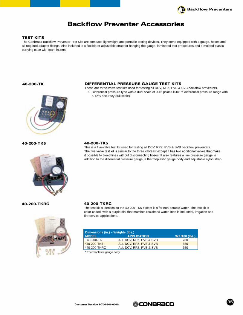
35
Backflow Preventers
Customer Service 1-704-841-6000
Backflow Preventer Accessories
40-200-TK DIFFERENTIAL PRESSURE GAUGE TEST KITSThese are three-valve test kits used for testing all DCV, RPZ, PVB & SVB backflow preventers.
• Differential pressure type with a dual scale of 0-15 psid/0-100kPa differential pressure range witha +2% accuracy (full scale).
TEST KITSThe Conbraco Backflow Preventer Test Kits are compact, lightweight and portable testing devices. They come equipped with a gauge, hoses andall required adapter fittings. Also included is a flexible or adjustable strap for hanging the gauge, laminated test procedures and a molded plasticcarrying case with foam inserts.
40-200-TK5 40-200-TK5This is a five-valve test kit used for testing all DCV, RPZ, PVB & SVB backflow preventers.The five valve test kit is similar to the three valve kit except it has two additional valves that make it possible to bleed lines without disconnecting hoses. It also features a line pressure gauge in addition to the differential pressure gauge, a thermoplastic gauge body and adjustable nylon strap.
40-200-TKRC 40-200-TKRCThe test kit is identical to the 40-200-TK5 except it is for non-potable water. The test kit is color-coded, with a purple dial that matches reclaimed water lines in industrial, irrigation and fire service applications.
Dimensions (in.) – Weights (lbs.)MODEL APPLICATION WT./100 (lbs.)
40-200-TK ALL DCV, RPZ, PVB & SVB 780*40-200-TK5 ALL DCV, RPZ, PVB & SVB 650*40-200-TKRC ALL DCV, RPZ, PVB & SVB 650* Thermoplastic gauge body

36
Backflow Preventers
Customer Service 1-704-841-6000
Series IBVE-125
40-200-ST SIGHT TUBEUsed in USC testing procedures. The kit allows for visual inspection during testing,provides an extension to the check valve body and offers quick connection with the90˚ elbow. Provides means to static test double check backflow preventers.
40-200-BV BLEED VALVETest valve used to provide accurate readings in field test of the Double CheckValve backflow preventers. Recommended in USC testing procedures. Benefitsinclude quick connections, quick bleed off of testing lines and usefulin tight locations.
40-00X-TFK TEST KIT FITTINGBrass fitting which installs onto Backflow Preventer Test Cocks by hand. Notools required. No messy Teflon® tape to deal with. Provides cleaner, quickertesting. (3 per kit) Sizes 1/4", 1/2", 3/4"
Accessories
EPOXY COATED CAST IRON FULL PORT CLASS 125 FLANGED BALL VALVEThe new Conbraco Series IBVE-125 ball valves feature an FDA-approved, heat fused epoxy coat-ing, making them ideal for corrosive water service as well as food contact applications. They can beused in place of any IBBM gate valve or plug valve.
With their full port design, these valves assure an unobstructed, turbulence-free flow that gate andbutterfly valves can’t match. Low profile handle for easy installation in tight places. Sizes from 21/2"to 8". Rated 125 WSP, 200 WOG, with maximum operating temperature of 140°F.
FEATURES
• Gear operator standard on 8"• Full port design offers superior
flow rate• No bronze seat rings, disc rings or
stems to wear out• Quarter turn offers instant, positive
shutoff with zero leakage• Stainless steel ball resists corrosion• Large actuator mounting pad
standard
• Optional locking handles available• Handle indicates valve operation status• Opens and closes easily, without
cheater bar• Blowout-proof stainless steel stem• PTFE seats and packing, not Nitrile
or EPDM• For more technical info ask for PHBRIRBV
brochure
MATERIALSBody FDA Approved epoxy-
coated cast ironSeats PTFE
Dimensions (in.) – Weights (lbs.)Model # SIZE A B C D E WT./LBS6Q20901 2-1/2" 7.5 7 5.9 16 1/2 NPT 346Q20001 3" 8 7.5 6.2 16 1/2 NPT 386Q20A01 4" 9 9 7 19.7 1/2 NPT 586Q20C01 6" 10.5 11 10.04 26 3/4 NPT 1186Q20E01 *8" 11.5 13.5 15.85 - 3/4 NPT 345NOTE: Gear operator standard on 8"
Model # SIZE40-000-TFK 1/4"40-001-TFK 1/2"40-002-TFK 3/4"

37
Backflow Preventers
Customer Service 1-704-841-6000
Accessories
40-200 & Model RP (4S-200) Backflow Preventers
AIR GAP DRAINFor installation with Conbraco’s 40-200 and 4S-200 Series Reduced Pressure Principle backflow preventers.
The Conbraco Air Gap Drain (AGD) is designed to funnel minor relief valve discharges, due to linepressure fluctuations and /or minor check valve fouling, into the drainage system. Drain piping iseasily attached to the drain’s threaded bottom.
Note: The AGD is NOT designed to collect the full discharge capacity of the relief valve.
Dimensions (in.) – Weights (lbs.)R.P. AGD40 Series Model No. A B C Wt./1001/4", 3/8", 1/2" 40-200-XA 8-7/16 5 1" NPT 2303/4" & 1" 40-200-X1 9-1/2 5-1/8 1" NPT 3401-1/4" & 2" 40-200-X1 11-1/4 5-1/8 1" NPT 3402-1/2" & 3" 40-200-X2 19 9-7/8 2" NPT 11004" 40-200-X2 20 9-7/8 2" NPT 11006" 40-200-X2 21 9-7/8 2" NPT 11008" 40-200-X3 22-11/16 12-11/16 3" NPT 124510" 40-200-X3 25-11/16 12-11/16 3" NPT 1245
Dimensions (in.) – Weights (lbs.)R.P. AGD4S Series Model No. A B C Wt./1002-1/2" - 4" 40-200-X1 13-11/16 5-1/8 1" NPT 3406" 40-200-X1 14-5/8 5-1/8 1" NPT 3408" & 10" 40-200-X2 23-3/4 9-13/16 2" NPT 1100
(40-200)
(40-200)
(4S-200)

38
Backflow Preventers
Customer Service 1-704-841-6000
Accessories
40-300-M METER SETTERThe Conbraco meter setter, 40-300-M Series is designed to adapt existing water meter installationsto include a dual check backflow preventer. This is accomplished without the expense of modifyingexisting piping or replacing the existing meter box. The standard configuration provides for the 300series dual check to be installed on the outlet side of the water meter at a 45 angle which makes iteasily accessible for testing and repair. The meter setter will accept a standard 5/8" or 5/8" x 3/4"water meter, 7-1/2" face to face. The meter setter is constructed of an 85-5-5-5 cast bronze bodywith a boss to accept other components such as a pressure relief valve, cast bronze union nutsdrilled to accept sealing wire for tamper proofing, heavy wall copper tubing bends and lead-free solder joints.
FEATURES
• Cast bronze (85-5-5-5) body• Corrosion resistant• Lead-free solder joints• Low head loss
• Easy installation• Maximum working pressure 175 psig• Operating temperature range 33°F-180°F
40 - 3 0 0 - M X
OPTIONS1 - 5/8" meter setter2 - 5/8" x 3/4" meter setter3 - 5/8" meter setter with
dual check4 - 5/8" x 3/4" meter setter
with dual check
Flow Curve
Dimensions (in.) – Weights (lbs.)MODEL NO. UNIT WT. (lbs.)40-300-M1 3.1740-300-M2 3.3640-300-M3 5.1440-300-M4 5.32

39
Backflow Preventers
Customer Service 1-704-841-6000
(4S-200)
Accessories
Series 4S Valve Setter SERIES 4S VALVE SETTERThe Conbraco valve setter is a support accessory used for installing the 4S Series backflow preventers.The valve setter is constructed of ductile iron and features fusion bonded epoxy coating, making itideal for corrosive water service. It also contains ANSI B16.1 Class 125 flanges and ANSI AWWAC153 A21.53-94 mechanical joints. It is suitable for supply pressures to 175 psig and operating temperatures from 32˚ to 140˚F.
40 - X- VS - X
OPTIONSF - Flange by FlangeM - Flange by Mech. JointJ - Mech. Joint by Mech. Joint
SIZE9 - 2-1/2" C - 6"0 - 3" E - 8"A - 4" G - 10"
MATERIALSValve Setter Ductile Iron ASTM
A536 Grade 65-45-12Coating Suitable For Potable
Water Service Nuts & Bolts* Zinc Plated Steel
*Center joint nut and bolts only (flange bolts andgaskets not included).
Flange x Mechanical JointSize Weight A B C3" DC/RP 85 28-1/8 5-1/8 45-7/84" DC 130 29-5/8 6-1/2 48-1/84" RP 135 31-5/8 6-1/2 50-1/86” DC 230 34-1/8 8 55-5/86" RP 250 37-5/8 8 59-1/88" DC 396 45 1/8 9 68-3/88" RP 422 47-5/8 9 8010" DC/RP 556 51-5/8 11 79
Mechanical Joint x Mechanical JointSize Weight A B C3" DC/RP 81 28-1/8 7 424" DC 107 29-5/8 7-1/2 44-5/84" RP 112 31-5/8 7-1/2 46-5/86” DC 185 34-1/8 9 52-5/86" RP 205 37-5/8 9 52-1/88" DC 323 45 1/8 10 65-1/88" RP 350 47-5/8 10 67-5/810" DC/RP 481 51-5/8 12 75-1/2
Flange x FlangeSize Weight A B C2-1/2" DC/RP 63 27-1/8 5 373" DC/RP 81 28-1/8 5-1/2 394" DC 131 29-5/8 6-1/2 42-1/24” RP 136 31-5/8 6-1/2 44-1/26" DC 220 34-1/8 8 506" RP 238 37-5/8 8 53-1/88" DC 378 45-1/8 9 638" RP 405 47-5/8 9 65-1/210" DC/RP 580 51-5/8 11 73-1/2
DC
RP
DC
RP
DC
RP
Notes:• 2-1/2" size not available with
mechanical joint.• Mechanical joint sold without
accessories.
• Approximate weights are shown.• Nominal dimensions are shown.• For normal manufacturing
tolerances, allowances must be made.

40
Backflow Preventers
Customer Service 1-704-841-6000
TYPICAL INSTALLATION
Relief valve shown rotated 90˚. Valve should beassembled w/hose barb pointed out of page.
16-601
78-RV
ORDERING NUMBER
Accessories
78-RV THERMAL EXPANSION RELIEF VALVES (SERIES 16-601 & 78-RV)The Conbraco Thermal Expansion Relief Valves (Series 16-601 and 78-RV) are designed primarilyto relieve excessive water pressure build-up caused by thermal expansion.
In a closed hot water piping system, as water is heated, thermal expansion occurs. The increase ofpressure will exert unwarranted stress on the system components, which may reach harmful levelswell before the emergency setting of the main relief valve is reached. By installing the Series 16-601 or the 78-RV, it will control any amount of expanded water without causing pressureincrease to exceed maximum setting.
FEATURES
• Prevents excessive pressure build-up• Protects plumbing fixtures• Extends water heater life• Compact and lightweight design
• Economical• Easy to install and requires no special tool• Corrosion resistant
Note: Unit can be mounted on 1/2" thru 1" Copper Tubing.
Dimensions (in.) – Weights (lbs.)Series A B C78-300 2.6 3.9 3.278-400 2.5 2.7 3.4
78 - X X X- R V
PRESSURE SETTING0 - 125 psig1 - 100 psig2 - 80 psi
RELIEF VALVE CONNECTION4 - Hose Barb5 - Pex6 - Comp. Fitting7 - 1/2" NPT/SWT Fitting
SIZE3 - 3/4" SWT4 - 3/4" THD5 - 1" SWT6 - 1" THD
16-601 Series
Model Set Pressure (PSI) Unit WT.
16-601-E6 85 0.5 lb. 16-601-03 00 0.5 lb.16-601-04 25 0.5 lb.

41
Backflow Preventers
Customer Service 1-704-841-6000
Accessories
W-8078-00 3/4" HOSE CONNECTION PRESSURE GAUGEThe Conbraco Hose Connection Pressure Gauge is designed to measure water pressure through a 3/4" hose thread connection. It consists of an indicator needle to determine maximum pressure.
FEATURES
• 2-1/2" face dial• 0 - 300 psig pressure range• Swivel type 3/4" hose connection
• Adjustable indicator needle• Temperature range = 50°F - 130°F• Wt./100 46.0
Dimensions (in.) – Weights (lbs.)
Model Capacity Exp. Vol. Connection A B Net Wt.No. (gal.) (gal.) (in.) (in.) (lbs.)
40-XT1-01 2.11 1.40 3/4 NPT 10.88 8.00 5.540-XT3-01 4.76 3.17 3/4 NPT 13.75 10.75 8.140-XT5-01 6.34 4.22 3/4 NPT 15.88 12.00 9.740-XT7-01 13.21 8.82 3/4 NPT 20.00 15.00 23.4
40-XT Series THERMAL EXPANSION TANKDesigned to protect closed water supply systems, appliances and piping from the hazards of thermal expansion, such as premature water heater failure. Installs easily on direct fired gas, oil and electric hot water heaters and storage tanks. Their pre-pressurized steel design includes anexpansion membrane that stops any contact between the water and air in the tank.
FEATURES
• Baked on epoxy liner• Butyl diaphragm• Designed for easy inline installation
• Pre-charge is adjustable in the field• For use with storage tanks and water heaters

42
Backflow Preventers
Customer Service 1-704-841-6000
59 Series Y STRAINER
FEATURES• Maximum protection capability against foreign
particles in piping systems andprocess equipment.
• Cast bronze (81-3-7-9) body• 304 Stainless Steel screen• Sizes 1/8" thru 1/2" comes standard with 50
mesh (0.009" wire)• Sizes 3/4" thru 3" comes standard with 20 mesh
(0.016" wire)
• 4" size comes standard with .125" perforated screen
• Operating pressure to 400 psig WOG• Removable self-aligning screen
FC1 FLANGED MODELS, STYLE FC1 CLASS 125
FEATURES• Maximum protection capability against foreign
particles in piping systems andprocess equipment.
• High tensile ASTM A126 Class B cast iron bodycoated with FDAApproved epoxy.
• 18-8 stainless steel screen
• Sizes 2-1/2" and 3" come standard with 0.045"perforation screen. Sizes 4" thru 10" come standard with 0.125" perforation screen
• Operating pressure to 200 psig• Removable self-aligning screen• Provided with crane hook hole in the vertical fin
on 4" and above for ease of lifting and positioning
Accessories
Dimensions (in.) – Weights (lbs.)Cap Tapping
Model Size A B Suffix-02 Wt./100
59-000-01 1/8 NPT 2 1-1/4 1/8 NPT 44.559-001-01 1/4 NPT 2 1-1/4 1/8 NPT 42.559-002-01 3/8 NPT 2-11/16 2 1/4 NPT 78.659-003-01 1/2 NPT 2-11/16 2 1/4 NPT 75.159-004-01 3/4 NPT 3-7/8 3-1/4 1/2 NPT 18559-005-01 1 NPT 4-3/4 4 3/4 NPT 27659-006-01 1-1/4 NPT 5-1/8 4-1/4 3/4 NPT 35859-007-01 1-1/2 NPT 5-3/4 5 1 NPT 54159-008-01 2 NPT 6-3/4 6 1-1/4 NPT 74759-009-01 2-1/2 NPT 7-15/16 5-7/8 1-1/4 NPT 113059-010-01 3 NPT 9-1/8 6-7/8 1-1/4 NPT 158059-011-01 4 NPT 11-15/16 10-1/8 1-1/2 NPT 3070
Dimensions (in.) – Weights (lbs.)SIZE WEIGHT
MODEL SIZE A B BLOW-OFF NPT (LBS.)
6132C9L1 2-1/2" 10-1/2 7 1-1/4 336132C0L1 3" 12 8 1-1/4 446132CAN1 4" 14-7/8 10-3/4 1-1/4 856132CCN1 6" 21 16-1/4 1-1/2 1746132CEN1 8" 22-1/2 17 2 2626132CGN1 10" 26-1/2 20-1/4 2-1/2 410NOTE: Conbraco offers a complete line of threaded and flanged end strainers. For details, contact your local sales representative.
A
B
A
B

43
Backflow Preventers
Customer Service 1-704-841-6000
APPROVALS
Type of Device Model/Series SIZE APPROVALSUSC ASSE CSA IAPMO AWWA UL* FM*
Double Check 40-100 1/2"-2" YES 1015 B64.5 YES C-510 N/A N/ADouble Check (Top Entry) 40-100 3/4"-2" YES 1015 B64.5 YES C-510 YES N/ADouble Check (Top Entry) 40-100-T2 3/4"-2" YES 1015 B64.5 PENDING C-510 N/A N/ADouble Check (Top Entry) 40-100-TC2 3/4"-1" YES 1015 B64.5 PENDING C-510 N/A N/ADouble Check 40-100-02 2-1/2"-10" YES 1015 B64.5 YES C-510 N/A N/ADouble Check 40-100-03 2-1/2"-10" YES 1015 B64.5 YES C-510 YES YESDouble Check 40-100-05 2-1/2"-6" YES 1015 B64.5 PENDING C-510 N/A N/ADouble Check 40-100-06 4"-10" YES 1015 B64.5 YES C-510 N/A N/ACarbonated Beverage Back. Prev. CBBP/4C-100 1/4"-3/8" N/A 1022 B64.3.1 PENDING N/A N/A N/ADouble Check DC/4S-100 1/2" YES 1015 B64.5 PENDING PENDING N/A N/ADouble Check DC/4S-100 2-1/2"-6" YES 1015 B64.5 YES C-510 YES YESDouble Check DC/4S-100 8"&10" YES 1015 B64.5 PENDING C-510 YES YESReduced Pressure 40-200 1/4"-1/2" YES 1013 B64.4 N/A N/A N/A N/AReduced Pressure 40-200 3/4"-2" YES 1013 B64.4 YES C-511 YES N/AReduced Pressure 40-200-T2 1/4"-1/2" YES 1013 B64.4 N/A N/A N/A N/AReduced Pressure 40-200-T2 3/4"-2" YES 1013 B64.4 PENDING C-511 N/A N/AReduced Pressure 40-200-TC2 3/4"-1" YES 1013 B64.4 PENDING N/A N/A N/AReduced Pressure 40-200-A2S 1/4"-1" YES 1013 1/2"-1" PENDING N/A 3/4", 1" N/AReduced Pressure 40-200-T2S 1/4"-1" PENDING 1013 1/2"-1" PENDING N/A N/A N/AReduced Pressure 40-200-A2U, Z 3/4"-2" YES 1013 B64.4 PENDING N/A N/A N/AReduced Pressure 40-200-T2U, Z 3/4"-2" PENDING 1013 B64.4 PENDING N/A N/A N/AReduced Pressure 40-200-TCU 3/4"-1" YES 1013 B64.4 PENDING N/A N/A N/AReduced Pressure 40-200-02 2-1/2"-10" YES 1013 B64.4 YES C-511 N/A N/AReduced Pressure 40-200-03 2-1/2"-10" YES 1013 B64.4 YES C-511 3"-10" YESReduced Pressure 40-200-05 2-1/2"-6" YES 1013 B64.4 PENDING C-511 N/A N/AReduced Pressure RP/4S-200 2-1/2"-6" PENDING 1013 B64.4 PENDING PENDING YES YESReduced Pressure RP/4S-200 8"-10" PENDING 1013 B64.4 PENDING PENDING YES YESDual Check 40-300 1/2"-1" N/A 1024 B64.6 N/A N/A N/A N/ADual Check 4P-300 1/2"-1" N/A 1024 B64.6 N/A N/A N/A N/AContinuous Pressure B.P. 40-400 1/2"-3/4" N/A 1012 B64.3 N/A N/A N/A N/AContinuous Pressure B.P. 4J-400 1/2"-3/4" N/A 1012 B64.3 N/A N/A N/A N/APressure Vacuum Breaker 40-500 1/2"-2" YES 1020 B64.1.2 PENDING N/A N/A N/APressure Vacuum Breaker PVB/4V-500 1/2"-2" YES 1020 B64.1.2 YES N/A N/A N/APressure Vacuum Breaker PVB/4V-500-TC2 3/4"-1" PENDING PENDING PENDING PENDING N/A N/A N/ASpill-Resistant PVB SVB/4W-500 1/4"-1/2" YES 1056 B64.1.2 YES N/A N/A N/ADouble Check Detector Assy 40-600 3"-10" YES 1048 N/A N/A N/A YES YESDouble Check Detector Assy DCDA/4S-600 2-1/2"-6" YES 1048 N/A N/A N/A YES YESDouble Check Detector Assy DCDA/4S-600 8"& 10" YES 1048 N/A N/A N/A YES YESReduced Pressure Detector Assy 40-700 3"-10" YES 1047 N/A N/A N/A YES YESAtmospheric Vacuum Breaker 38-100 1/4"-2" N/A 1001 B64.1.1 YES N/A N/A N/AAtmospheric Vacuum Breaker 38-200 1/4"-1/2" N/A 1001 B64.1.1 YES N/A N/A N/AHose Conn. Vacuum Breaker 38-304 3/4" N/A 1011 B64.2 YES N/A N/A N/AHose Conn. Vacuum Breaker 38P 3/4" N/A 1011 B64.2 YES N/A N/A N/AHose Conn. Backflow Preventer 38-304-02 3/4" N/A 1052 PENDING PENDING N/A N/A N/AAnti-Freeze Hose Conn. V.B 38-404 3/4" N/A 1011 B64.2 YES N/A N/A N/ALab Faucet Vacuum Breaker 38-500 1/4"-3/8" N/A 1035 B64.7 YES N/A N/A N/A
Approved for horizontal and vertical installation* Must have indicating type shut-off valves Note: For specific USC approved devices, please see the "FCCCHR" official listing.

44
Backflow Preventers
Customer Service 1-704-841-6000
WARRANTY & LIMITATIONS OF LIABILITY
Conbraco Industries, Inc. warrants, to its initial purchaser only, that its products which are delivered to this initial pur-chaser will be of the kind described in the order or price list and will be free of defects in workmanship or material for aperiod of one year from the date of delivery to you, our initial purchaser.
Should any failure to conform to this warranty appear within one year after the date of the initial delivery to our initialpurchaser, Conbraco will, upon written notification thereof and substantiation that the goods have been stored,installed, maintained and operated in accordance with Conbraco’s recommendations and standard industry practice,correct such defects by suitable repair or replacement at Conbraco’s own expense.
THIS WARRANTY IS EXCLUSIVE AND IS IN LIEU OF ANY IMPLIED WARRANTY OF MERCHANTABILITY,FITNESS FOR A PARTICULAR PURPOSE OR OTHER WARRANTY, WHETHER EXPRESSED OR IMPLIED,EXCEPT THE WARRANTY OF TITLE AND AGAINST PATENT INFRINGEMENT. Correction of non-conformities, inthe manner and for the period of time provided above, shall constitute fulfillment of all liabilities of Conbraco to ourinitial purchaser, with respect to the goods, whether based on contract, negligence, strict tort or otherwise. It is theintention of Conbraco Industries, Inc. that no warranty of any kind, whether express or implied shall pass through ourinitial purchaser to any other person or corporation.
LIMITATION OF LIABILITY: Conbraco Industries, Inc. SHALL NOT UNDER ANY CIRCUMSTANCES BE LIABLE FORSPECIAL OR CONSEQUENTIAL DAMAGES SUCH AS, BUT NOT LIMITED TO, DAMAGE TO OR LOSS OF OTHERPROPERTY OR EQUIPMENT, LOSS OF PROFITS OR REVENUE, COST OF CAPITAL, COST OF PURCHASEDOR REPLACEMENT GOODS, OR CLAIMS OF CUSTOMERS OF OUR INITIAL PURCHASER. THE REMEDIES OFOUR INITIAL PURCHASER, AND ALL OTHERS, SET FORTH HEREIN, ARE EXCLUSIVE, AND THE LIABILITY OFCONBRACO WITH RESPECT TO SAME SHALL NOT, EXCEPT AS EXPRESSLY PROVIDED HEREIN, EXCEEDTHE PRICE OF THE CONBRACO GOODS UPON WHICH SUCH LIABILITY IS BASED.

45
Backflow Preventers
Customer Service 1-704-841-6000
NOTES

46
Backflow Preventers
Customer Service 1-704-841-6000
NOTES

47
Backflow Preventers
Customer Service 1-704-841-6000
NOTES

For Representatives And Distributors In Your International AreaPlease Contact The Closest Conbraco Industries International Office.
Conway, SC • Matthews, NC • Pageland, SC • Customer Service 1-704-841-6000 • www.conbraco.com
Printed in USA COPYRIGHT 7/03 BFCA9000
Sout
heas
tRe
gion
Mid
wes
tern
Reg
ion
Wes
tern
Reg
ion
North
east
Re
gion
Sout
hern
Regi
onCa
nada
Int’l
./Pu
erto
Ric
o
E/Mail Address Phone FaxB. Lynch & Associates Florida [email protected] 813-901-0992 813-901-8403Valves & Fittings, Inc. Georgia/Alabama [email protected] 770-483-3057 770-483-3110Pro Marketing, Inc. North Carolina/South Carolina/Tennessee-East [email protected] 864-578-4334 864-578-4889Mid South Marketing, Inc. Virginia/Maryland/Washington, D.C./WV-East [email protected] 804-749-8712 804-749-8717
Southern Marketing Group MS/TN-West/AR/Bowie Cty.-TX [email protected] 901-547-0042 901-547-0035
AVC Mechanical Sales, Inc Oklahoma/Texas-North [email protected] 817-649-2229 817-649-2225
Knox & Associates Texas-South/Louisiana [email protected] 713-462-7766 713-690-6228
HEBCO, Inc. Kansas/Missouri-West [email protected] 913-491-0797 913-491-5126New Tech Marketing, Inc. IL/WI-East/IN-North/MI-Upper Peninsula/IA-River Counties [email protected] 630-378-4300 630-378-0343New Tech Marketing, Inc. Eastern Missouri/Southern Illinois [email protected] 618-394-0329 618-394-0427L.J. Whitfill & Associates Kentucky/Indiana-South/Ohio-South [email protected] 502-459-4545 502-459-9944V.E. Sales Co., Inc. Michigan (Except Upper Peninsula) [email protected] 586-774-7760 586-774-1490Northstar Valve & Fitting, Inc. Minnesota/North & South Dakota/Wisconsin-West [email protected] 952-937-0108 952-937-0803Willco, Inc. Nebraska/Iowa (Except River Counties) [email protected] 402-573-7000 402-573-7371Morrissey Associates, Inc. Ohio-North/Pennsylvania-West/West Virginia-West [email protected] 330-538-0406 330-538-0410
Pioneer Sales California-North [email protected] 916-388-0865 916-388-0867Specification Sales California-South [email protected] 909-594-7088 909-594-2798Marshall-Rodeno Associated CO/WY/MT/ID-SE/UT/NV-NE/NM/El Paso-TX [email protected] 303-575-6701 303-575-6706J.P. Harris & Associates, Inc. Washington/Oregon/Idaho-North West/Alaska [email protected] 360-944-8457 360-944-8459Layden Valve Sales & Solutions Hawaii [email protected] 808-456-3331 808-455-1064Southwestern Mechanical Sales Co. Arizona [email protected] 480-813-1313 480-813-2286
Nevada-SW [email protected] 702-368-2561 702-368-1784
Urell, Inc. Massachusetts/New England States [email protected] 617-923-9500 617-926-9414
McMahon Marketing, Inc. New York-Upstate/New York-West [email protected] 518-792-3350 518-792-3351
Continuous Sales Corporation New York-East/New Jersey-North [email protected] 516-248-5177 516-248-5187
J.A. Layden Co. Pennsylvania-East/Delaware/New Jersey-South [email protected] 610-353-2311 610-359-1299
Keith Engle & Associates OEM accounts [email protected] 610-827-9560 610-827-9561
Conbraco Industries, Canada 160 Pennsylvania Ave., Unit 3, Concord, Ontario L4K 4A9 [email protected] 905-761-6161 905-761-6666
Barclay Sales Ltd. British Columbia [email protected] 604-945-1010 604-945-3030
Dynamic Agencies, Ltd. Saskatchewan [email protected] 306-343-1901 306-343-1901
Tom Beggs Agencies Ltd. Manitoba/NW Ontario [email protected] 204-953-1900 204-774-6915
Task Controls, Inc. Ontario [email protected] 416-291-3004 416-754-3481
Agences J. Pierre Sylvain, Inc. Quebec [email protected] 450-655-9588 450-641-2737
Kern Industries, Ltd. Alberta-North [email protected] 780-451-2056 780-454-6687
J. Levandier Sales, Inc. Nova Scotia, New Brunswick, Prince Edward Island [email protected] 506-858-1615 506-858-1084
Smith Agencies Newfoundland [email protected] 709-364-8856 709-747-9414
Key to the North Sales Agency, Inc. Ontario-North [email protected] 705-524-6714 705-566-0148
Pelco Sales Eastern-Ontario/Ottawa [email protected] 613-839-0114 613-839-0115
Rafael Rodriguez Barril, Inc. Puerto Rico [email protected] 787-759-8680 787-759-8986
Conbraco International Limited Manchester, England [email protected] +44-161-908-2340 +44-161-908-2359
CUSTOMER SERVICE AND SALES DEPARTMENTSP.O. Box 247 • Matthews, NC 28106
Phone: 704-841-6000 • Fax: 704-841-6020