cobots: a novel material handling technology · controlled material handling device, which can...
TRANSCRIPT
COBOTS:A NOVEL MATERIAL HANDLING TECHNOLOGY
Witaya Wannasuphoprasit1 Prasad Akella2
Michael Peshkin1 J. Edward Colgate1
1 Dept. of Mechanical Engineering, Northwestern University, Evanston, IL 602082 General Motors Corporation, Manufacturing Center, M/C: 480-109-163, Warren, MI 48090-9040
ABSTRACTCobots are a class of hybrid human-controlled/computer-
controlled material handling device, which can enhanceergonomics, productivity, and safety. Cobots implementsoftware-defined virtual guiding surfaces, as well as providingsome amplification of human power ("power assist"). Cobotsmake use of steerable nonholonomic joints to produce theguiding surfaces that aid the operator. This unique steeringsystem, in place of powerful actuators, results in guidingsurfaces that are smooth, frictionless, and intrinsically stable --making cobots particularly appropriate for safety-critical tasks.
In this paper we describe the basic concepts of cobots withreference to laboratory prototypes having two or threeworkspace dimensions. Early industrial application inautomobile final assembly plants is underway, and two cobotspresently in industrial environments are described
MOTIVATIONThe General Assembly area of automobile plants, currently
relies on conventional material handling devices often called“assist devices”, examples of which are hoists and articulatingarms with pneumatic balancers. These primarily providegravity compensation. As the industry moves towards largermodular sub-systems (e.g., a 150-lb. cockpit system),cumulative trauma disorders resulting from maneuvering themhave become greater concerns. One application of cobots,highlighted in this paper, is a solution to the so-called “inertiamanagement” problem which arises frequently in the materialshandling industry in general, and in automobile final assemblyin particular. Moving heavy payloads, even with lift assistance,can nevertheless cause ergonomic stress due to problemsassociated with inertia management -- changes of direction andspeed -- as well as overcoming friction.
One solution involves the use of virtual guiding surfaces,which may be implemented by cobots. The guiding surfacesmay include, for example, a “virtual funnel” that directsworkpart motion towards a specific task location. Since thevirtual surfaces, implemented by a cobot, produce the largeforces necessary to redirect the motion of a payload, smallerhandling forces are required from the human operator. It isworth noting that full automation of vehicle final assembly isnot considered desirable, because of the many uniquecapabilities brought by human workers. However guidingsurfaces can reduce inertia management stresses, while cobotpower-assist can help the operator overcome friction and start-up inertia.
In addition to allowing the use of smaller handling forces,cobots help improve quality by decreasing human error,especially errors that result in collisions and workpart damage.Productivity can be improved by reducing the training periodrequired by new operators in learning the sometimes-complexmotion trajectories required. Further the speed at which anoperator can execute a trajectory can be increased if he or she isfollowing a virtual wall, rather than providing directional forcesmanually. Finally, great manufacturing flexibility is madepossible by being able to accommodate under software control,to several body styles being built on a single line.
We describe, in this paper, two categories of cobot: wheelbased cobots, and spherical joint based cobots. The firstcategory uses a rolling wheel as a cobot joint, and mainlyoperates on a floor. The second group employs a spherical jointto form articulated, revolute joint, or overhead rail cobots.While we will briefly discuss spherical joint cobots, our focushere is on wheel based cobots.
The simplest possible cobot is a human powered unicycle,which is steered by a servo system acting under computercontrol. The unicycle cobot has a two dimensionalconfiguration space (x-y in plane). This laboratory prototype
will be used to explain some basic cobot concepts. A tricyclecobot, nicknamed Scooter, has been built to explore kinematicsand controls of higher configuration space cobots, and this willbe described briefly as well
The paper also describes in some detail two industrialprototypes that have been built to date: a floor based cobot anda power assisted overhead rail cobot. These are currently beingevaluated at General Motors and Ford Motor Companyrespectively.
WHEEL BASED COBOTSUnicycle Cobot
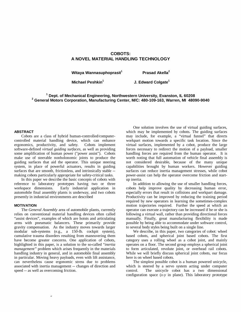
We first describe the simplest device, the Unicycle cobotshown in Fig. 1. The cobot mechanism consists of a free-rolling wheel in contact with a working surface. A small motorsteers the wheel, but cannot cause the cobot to move. Thewheel’s rolling velocity is monitored by an encoder, but it isnot driven by a motor. Only the operator can cause it to move,by applying forces to the handle. A force sensor monitors theseuser forces.
The unicycle cobot has a two-dimensional (planar, R = [x,y] T) configuration space corresponding to all possible locationsof the unicycle assembly in its planar workspace. Although theUnicycle has only one degree-of-freedom (DOF), it may, byproper steering, reach any point on the plane. Such is thenature of nonholonomic constraint. In operation, however,virtual constraint surfaces may be defined in software toprohibit entry into excluded regions of the plane.
Figure 1. The Unicycle cobot
The Unicycle cobot displays two essential behaviors:virtual caster, and virtual wall.
Virtual caster mode is invoked when the cobot’s positionin its planar workspace is away from all defined constraintsurfaces. The cobot should therefore permit any motion thatthe user attempts to impart. To do this, the steering angle of thewheel is servo-controlled such that user forces perpendicular tothe wheel’s rolling direction are nulled. The behavior is similarto that of a caster wheel on a rolling item of furniture, thoughthere is no physical caster at all.
When the user brings the cobot’s position in the plane to aplace where a constraint surface is defined, control of thesteering angle changes over to virtual wall mode. The wheel issteered such that its rolling direction becomes tangent to theconstraint surface, and this tangency is maintained as the usermoves the cobot in “virtual contact” with the constraint surface.The user perceives contact with a hard frictionless constraintsurface. In practice the illusion is convincing. The virtual wallmode is ended when the measured user forces are found to bedirected away from the constraint surface, at which pointvirtual caster mode resumes. A detailed discussion of virtualcaster and virtual wall control can be found in(Wannasuphoprasit, et al., 1997).
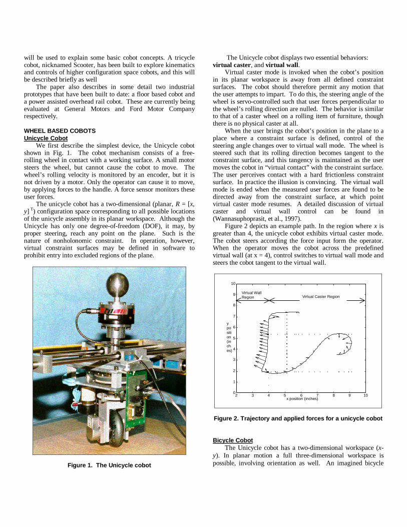
Figure 2 depicts an example path. In the region where x isgreater than 4, the unicycle cobot exhibits virtual caster mode.The cobot steers according the force input form the operator.When the operator moves the cobot across the predefinedvirtual wall (at x = 4), control switches to virtual wall mode andsteers the cobot tangent to the virtual wall.
2 3 4 5 6 7 8 9 100
1
2
3
4
5
6
7
8
9
10
x position (inches)
yposition(inches)
Virtual Caster RegionVirtual WallRegion
Figure 2. Trajectory and applied forces for a unicycle cobot
Bicycle CobotThe Unicycle cobot has a two-dimensional workspace (x-
y). In planar motion a full three-dimensional workspace ispossible, involving orientation as well. An imagined bicycle
cobot, illustrated in Fig. 3, could implement x, y, and angularconstraint. This machine consists of two independentlysteerable wheels whose shafts are held a fixed distance fromone another. Although it has a larger configuration space thanthe Unicycle, the bicycle has the same number of degrees offreedom: just one; any motion of the bicycle can be describedas a rotation about a center-of-rotation (COR), specified by thepoint of intersection of the two wheel axes. However thelocation of this COR can be changed in real time by steering. Itis true of cobots in general that there is one mechanical degreeof freedom, but that the corresponding direction is servocontrolled by “steering” (with an appropriately broad definitionof “steering”).
center of rotation (COR)
Figure 3. Bicycle Cobot
In the Bicycle example we can begin to see that, like otherrobotic mechanisms, cobots exhibit singularities. In the case ofthe bicycle, it is not possible to specify a center of rotation onthe line that passes through the two wheel shafts. If we attemptto do so, the two wheels will both be aimed perpendicular tothis line. In this configuration, the machine actually gains adegree of freedom, going from one to two (of course, weusually think of singularities as reducing the DOF).
One way to solve this problem is to add a third wheelwhose shaft is not collinear with the other two.
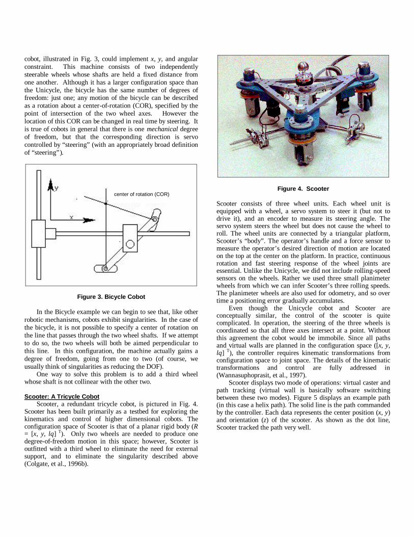
Scooter: A Tricycle CobotScooter, a redundant tricycle cobot, is pictured in Fig. 4.
Scooter has been built primarily as a testbed for exploring thekinematics and control of higher dimensional cobots. Theconfiguration space of Scooter is that of a planar rigid body (R= [x, y, lθ] T). Only two wheels are needed to produce onedegree-of-freedom motion in this space; however, Scooter isoutfitted with a third wheel to eliminate the need for externalsupport, and to eliminate the singularity described above(Colgate, et al., 1996b).
Figure 4. Scooter
Scooter consists of three wheel units. Each wheel unit isequipped with a wheel, a servo system to steer it (but not todrive it), and an encoder to measure its steering angle. Theservo system steers the wheel but does not cause the wheel toroll. The wheel units are connected by a triangular platform,Scooter’s “body”. The operator’s handle and a force sensor tomeasure the operator’s desired direction of motion are locatedon the top at the center on the platform. In practice, continuousrotation and fast steering response of the wheel joints areessential. Unlike the Unicycle, we did not include rolling-speedsensors on the wheels. Rather we used three small planimeterwheels from which we can infer Scooter’s three rolling speeds.The planimeter wheels are also used for odometry, and so overtime a positioning error gradually accumulates.
Even though the Unicycle cobot and Scooter areconceptually similar, the control of the scooter is quitecomplicated. In operation, the steering of the three wheels iscoordinated so that all three axes intersect at a point. Withoutthis agreement the cobot would be immobile. Since all pathsand virtual walls are planned in the configuration space ([x, y,lθ] T), the controller requires kinematic transformations fromconfiguration space to joint space. The details of the kinematictransformations and control are fully addressed in(Wannasuphoprasit, et al., 1997).
Scooter displays two mode of operations: virtual caster andpath tracking (virtual wall is basically software switchingbetween these two modes). Figure 5 displays an example path(in this case a helix path). The solid line is the path commandedby the controller. Each data represents the center position (x, y)and orientation (z) of the scooter. As shown as the dot line,Scooter tracked the path very well.
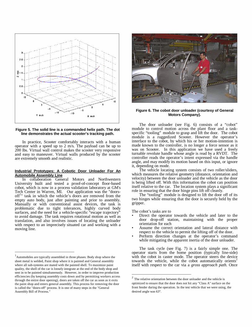
Figure 5. The solid line is a commanded helix path. The dotline demonstrates the actual scooter’s tracking path.
In practice, Scooter comfortably interacts with a humanoperator with a speed up to 2 m/s. The payload can be up to200 lbs. Virtual wall control makes the scooter very responsiveand easy to maneuver. Virtual walls produced by the scooterare extremely smooth and realistic.
Industrial Prototypes: A Cobotic Door Unloader For AnAutomobile Assembly Line
In collaboration General Motors and NorthwesternUniversity built and tested a proof-of-concept floor-basedcobot, which is now in a process validation laboratory at GM'sTech Center in Warren, MI. Our application was the "doors-off1" task in which the vehicle’s doors are removed from theempty auto body, just after painting and prior to assembly.Manually or with conventional assist devices, the task isproblematic due to tight tolerances, highly curved bodysurfaces, and the need for a vehicle-specific “escape trajectory”to avoid damage. The task requires rotational motion as well astranslation, and also involves issues of locating the unloaderwith respect to an imprecisely situated car and working with amoving line.
1Automobiles are typically assembled in three phases: Body shop where thesheet metal is welded, Paint shop where it is painted and General assemblywhere all sub-systems are mated with the painted shell. To maximize paintquality, the shell of the car is loosely integrate at the end of the body shop andsent in to be painted simultaneously. However, in order to improve productionefficiencies (by keeping assembly costs down and by permitting workers accessthrough the entire door opening), doors are taken off the car as soon as it exitsthe paint shop and enters general assembly. This process for removing the dooris called the "doors-off" process. It is one of many steps in the "GeneralAssembly Bill of Process."
Figure 6. The cobot door unloader (courtesy of GeneralMotors Company).
The door unloader (see Fig. 6) consists of a “cobot”module to control motion across the plant floor and a task-specific “tooling” module to grasp and lift the door. The cobotmodule is a ruggedized Scooter. However the operator’sinterface to the cobot, by which his or her motion-intention ismade known to the controller, is no longer a force sensor as itwas on Scooter. In this application we have used a freelyturnable revolute handle whose angle is read by a RVDT. Thecontroller reads the operator’s intent expressed via the handleangle, and may modify its motion based on this input, or ignoreit, depending on mode.
The vehicle locating system consists of two roller/sliders,which measures the relative geometry (distance, orientation andvelocity) between the door unloader and the vehicle as the dooris being lifted off. With this information the cobot can positionitself relative to the car. The location system plays a significantrole in ensuring that the door hinge pins lift off cleanly.
The “tooling” module is designed to lift the door off of itstwo hinges while ensuring that the door is securely held by thegripper.
The cobot’s tasks are to• Direct the operator towards the vehicle and later to the
door drop-off station, maintaining with the properorientation for each
• Assume the correct orientation and lateral distance withrespect to the vehicle to permit the lifting off of the door.
• Perform direction changes at the operator’s commandwhile mitigating the apparent inertia of the door unloader.
The task cycle (see Fig. 7) is a fairly simple one. Theoperator starts from the home position (typically line-side)with the cobot in caster mode. The operator steers the devicetowards the vehicle, while the cobot automatically orients2
itself with respect to the car via a gross approach path. Once
2 The relative orientation between the door unloader and the vehicle isoptimized to ensure that the door does not hit any "Class A" surface on thefront fender during the operation. In the test vehicle that we were using, thedesired angle was 63°.

the vehicle sensing system engages the side of the car, theunloader switches to fine approach path mode, adjusting itsorientation to match that of the particular vehicle. It alsocontrols the offset distance between the vehicle and theunloader. The operator pushes a button to grasp the door andanother to lift it. Upon door lift-off the velocities of theunloader and the vehicle become independent. The systemtriggers on this signal to execute an escape path that guides thedoor away from the vehicle as quickly and safely as possible.The operator now regains control of the unloader and steers itin virtual caster mode towards the drop off station. Theunloader orients itself with respect to the drop off station as itapproaches. When the vehicle sensing system engages, theunloader executes a fine return path that tunes its orientationand position for dropping off the door. The operator transfersthe door to the door trim line and is then ready to repeat thecycle.
X inch
Y
icnh
Home stand
Historic path of cobot door unloader
fine return
fine approach
escape
Figure 7. A typical trajectory followed by the cobotic doorunloader. For purposes of visualization, the vehicle and the
home stand part of the drop off station are also shown(though, not to scale).
The door unloader uses dead-reckoning (based on therotation of the wheels) to calculate its position at any instant oftime. This method is susceptible to accumulated errors. Toovercome this problem we exploited the fact that the device hasa fixed point during every cycle -- at the drop off station. Thus,as the door is being transferred to the door trim line the deviceis 'zeroed' out. Figure 7 shows a typical path followed by theoperator during a cycle.
One motivation was inertia management -- handlingmotions so that the apparent inertia that the operator feels isminimized. Despite the design team's concern about a loadedmass was in excess of 136 kg, most operators reported findingthe door unloader to be very easy to maneuver -- startup forcewas typically less than 25N (5 pounds). Low rolling frictioncontributes to this good result, and equally importantly thecobot does not “waste” momentum – changes of direction arehandled by steering rather than braking. The operator,
consequently, does not have to supply acceleration anddeceleration forces that commonly cause fatigue.
X inch
Z rad.
Cobot’s orientation (in rad.) VS lateral distance
Figure 8. The orientation trajectory corresponding to the(x,y) trajectory shown in Figure 7.
Preliminary tests indicate that the prototype door unloaderpromises significant improvements in (1) ergonomics, byminimizing the operator's twisting and lateral forces; (2)productivity, by decreasing the time to master the use of thedevice and by reducing cycle time; (3) quality, by reducing thescope for human error; and (4) safety, because of the passivityof the cobot. Efforts to quantify these improvements are on-going.
SPHERICAL JOINT COBOTSAll the cobots presented above are wheel based cobots,
which must operate on a planar working surface. In this section,we briefly introduce the other cobot element, a spherical joint.The spherical joints are used in place of steerable wheels forcobots with revolute joints, such as articulated cobots.However our first application has been to an industrial x-yoverhead rail cobot, which uses two spherical joints. For adiscussion of other applications of the spherical joint, and moredetails, please see Peshkin et al. (1996, 1998).
Spherical JointThe servo-steered wheel above can be thought of as a CVT
(Continuous Variable Transmission): it wheel controls the ratioof velocities in x and y axis. The transmission ratio between Vxand Vy of the wheel’s steering shaft depends on the steeringangle, α. This ratio can be adjusted without limit by steeringthe wheel. This relationship may be written as Vy/Vx = tan(α).The wheel may thus be considered to be a translational CVT: itconstrains the ratio of two translational velocities
Vx
Vy
αsteering angle
drive roller
d
d
2
1
ω 1
α
steering angle
follower
steering roller
drive roller
follower
axis of sphere
ω 2
ω
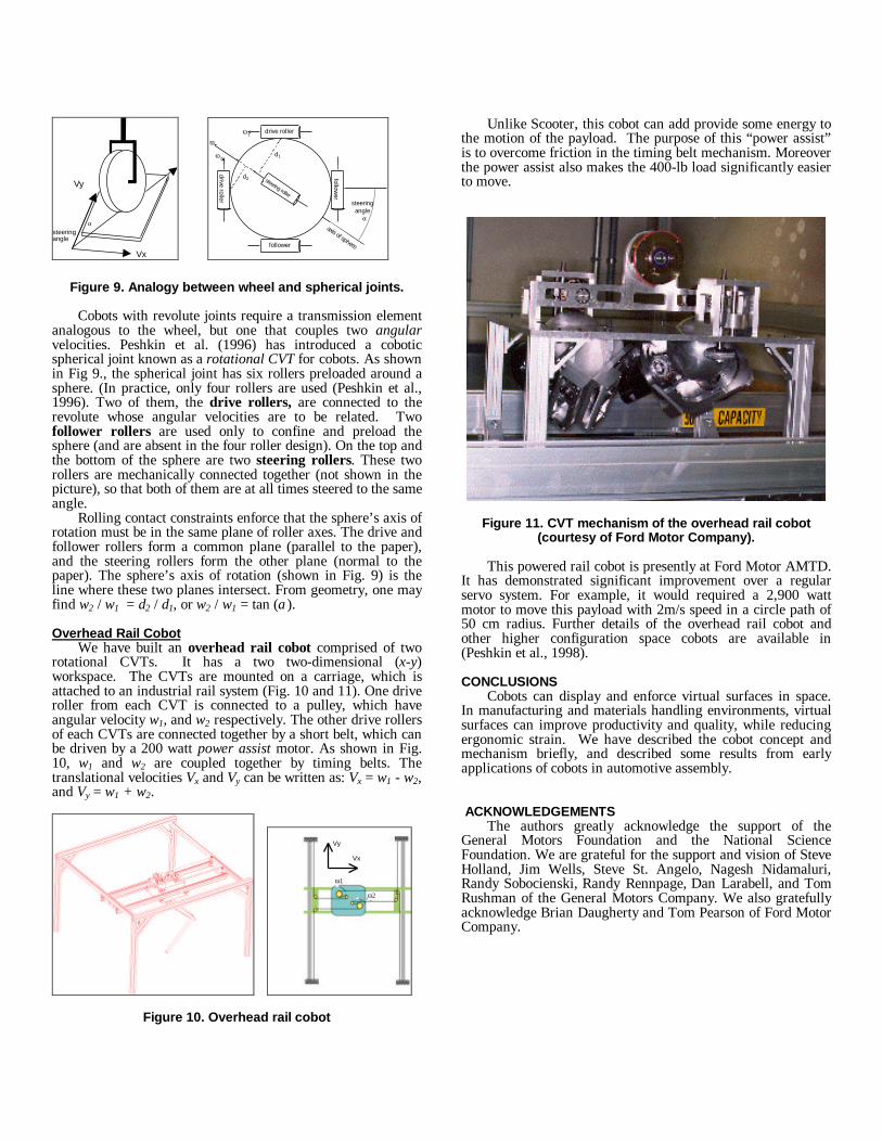
Figure 9. Analogy between wheel and spherical joints.
Cobots with revolute joints require a transmission elementanalogous to the wheel, but one that couples two angularvelocities. Peshkin et al. (1996) has introduced a coboticspherical joint known as a rotational CVT for cobots. As shownin Fig 9., the spherical joint has six rollers preloaded around asphere. (In practice, only four rollers are used (Peshkin et al.,1996). Two of them, the drive rollers, are connected to therevolute whose angular velocities are to be related. Twofollower rollers are used only to confine and preload thesphere (and are absent in the four roller design). On the top andthe bottom of the sphere are two steering rollers. These tworollers are mechanically connected together (not shown in thepicture), so that both of them are at all times steered to the sameangle.
Rolling contact constraints enforce that the sphere’s axis ofrotation must be in the same plane of roller axes. The drive andfollower rollers form a common plane (parallel to the paper),and the steering rollers form the other plane (normal to thepaper). The sphere’s axis of rotation (shown in Fig. 9) is theline where these two planes intersect. From geometry, one mayfind ω2 / ω1 = d2 / d1, or ω2 / ω1 = tan (α).
Overhead Rail CobotWe have built an overhead rail cobot comprised of two
rotational CVTs. It has a two two-dimensional (x-y)workspace. The CVTs are mounted on a carriage, which isattached to an industrial rail system (Fig. 10 and 11). One driveroller from each CVT is connected to a pulley, which haveangular velocity ω1, and ω2 respectively. The other drive rollersof each CVTs are connected together by a short belt, which canbe driven by a 200 watt power assist motor. As shown in Fig.10, ω1 and ω2 are coupled together by timing belts. Thetranslational velocities Vx and Vy can be written as: Vx = ω1 - ω2,and Vy = ω1 + ω2.
Vx
Vy
ω2
ω1
Figure 10. Overhead rail cobot
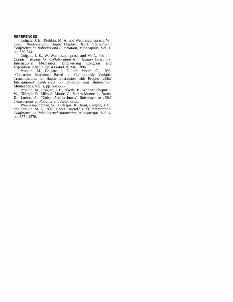
Unlike Scooter, this cobot can add provide some energy tothe motion of the payload. The purpose of this “power assist”is to overcome friction in the timing belt mechanism. Moreoverthe power assist also makes the 400-lb load significantly easierto move.
Figure 11. CVT mechanism of the overhead rail cobot(courtesy of Ford Motor Company).
This powered rail cobot is presently at Ford Motor AMTD.It has demonstrated significant improvement over a regularservo system. For example, it would required a 2,900 wattmotor to move this payload with 2m/s speed in a circle path of50 cm radius. Further details of the overhead rail cobot andother higher configuration space cobots are available in(Peshkin et al., 1998).
CONCLUSIONSCobots can display and enforce virtual surfaces in space.
In manufacturing and materials handling environments, virtualsurfaces can improve productivity and quality, while reducingergonomic strain. We have described the cobot concept andmechanism briefly, and described some results from earlyapplications of cobots in automotive assembly.
ACKNOWLEDGEMENTSThe authors greatly acknowledge the support of the
General Motors Foundation and the National ScienceFoundation. We are grateful for the support and vision of SteveHolland, Jim Wells, Steve St. Angelo, Nagesh Nidamaluri,Randy Sobocienski, Randy Rennpage, Dan Larabell, and TomRushman of the General Motors Company. We also gratefullyacknowledge Brian Daugherty and Tom Pearson of Ford MotorCompany.
REFERENCESColgate, J. E., Peshkin, M. A. and Wannasuphoprasit, W.,
1996, "Nonholonomic Haptic Display," IEEE InternationalConference on Robotics and Automation, Minneapolis, Vol. 1,pp. 539-544.
Colgate, J. E., W. Wannasuphoprasit and M. A. Peshkin.Cobots: Robots for Collaboration with Human Operators.International Mechanical Engineering Congress andExposition. Atlanta. pp. 433-440, ASME, 1996.
Peshkin, M., Colgate, J. E. and Moore, C., 1996,"Constraint Machines Based on Continuously VariableTransmissions, for Haptic Interaction with People," IEEEInternational Conference on Robotics and Automation,Minneapolis, Vol. 1, pp. 551-556.
Peshkin, M., Colgate, J. E., Akella, P., Wannasuphoprasit,W., Gillespie B., Mills A, Moore, C., Santos-Munne, J., Burns,D., Lorenz A., "Cobot Architechture," Submitted to IEEETransactions on Robotics and Automation.
Wannasuphoprasit, W., Gillespie, R. Brent, Colgate, J. E.,and Peshkin, M. A. 1997, "Cobot Control," IEEE InternationalConference on Robotics and Automation, Albuquerque, Vol. 4,pp. 3571-3576.