code-division multiplexing based hardware reduction for a … · 2018-11-15 · code-division...
TRANSCRIPT

MITSUBISHI ELECTRIC RESEARCH LABORATORIEShttp://www.merl.com
Code-Division Multiplexing based Hardware Reduction for aDigital Beamforming Transmitter Array
Peng, Z.; Kim, K.J.; Wang, P.; Ma, R.; Kihira, K.; Fukasawa, T.; Li, C.; Wang, B.
TR2018-049 July 10, 2018
AbstractThis paper proposes a new system architecture to reduce the hardware cost for a digitalbeamforming (DBF) transmitter array. In a conventional DBF transmitter array, each signalchannel requires a digitalto-analog converter (DAC) to convert the digital signal to the analogsignal, so that the cost and power consumption for such systems are often prohibitively highas the array size increases. In the proposed DBF transmitter array system, code-divisionmultiplexing (CDM) technique is used to combine digital signals from different channels,and thus the required number of DACs can be significantly reduced. The combined signalis separated by demodulation with the corresponding code sequences for each channel afterthe DAC. Principle of CDM for hardware reduction in a DBF array system is analyzed. Asystem-level simulation is performed in Simulink to verify the performance of the proposedsystem. Simulation results show that the beamforming accuracy and signal quality can bemaintained with a reduced number of DACs.
European Conference on Antennas and Propagation (EuCAP)
This work may not be copied or reproduced in whole or in part for any commercial purpose. Permission to copy inwhole or in part without payment of fee is granted for nonprofit educational and research purposes provided that allsuch whole or partial copies include the following: a notice that such copying is by permission of Mitsubishi ElectricResearch Laboratories, Inc.; an acknowledgment of the authors and individual contributions to the work; and allapplicable portions of the copyright notice. Copying, reproduction, or republishing for any other purpose shall requirea license with payment of fee to Mitsubishi Electric Research Laboratories, Inc. All rights reserved.
Copyright c© Mitsubishi Electric Research Laboratories, Inc., 2018201 Broadway, Cambridge, Massachusetts 02139


Code-Division Multiplexing based HardwareReduction for a Digital Beamforming
Transmitter ArrayZhengyu Peng1,3, Kyeong Jin Kim1, Pu Wang1, Rui Ma1, Kazunari Kihira2,
Toru Fukasawa2, Changzhi Li3, Bingnan Wang1,*
1Mitsubishi Electric Research Laboratories (MERL), Cambridge, MA, USA *[email protected] Technology R&D Center, Mitsubishi Electric Corporation, 5-1-1 Ofuna, Kamakura-shi, Japan
3Dept. of Electrical and Computer Engineering, Texas Tech University, Lubbock, TX, USA
Abstract—This paper proposes a new system architec-ture to reduce the hardware cost for a digital beam-forming (DBF) transmitter array. In a conventional DBFtransmitter array, each signal channel requires a digital-to-analog converter (DAC) to convert the digital signal tothe analog signal, so that the cost and power consumptionfor such systems are often prohibitively high as thearray size increases. In the proposed DBF transmitterarray system, code-division multiplexing (CDM) tech-nique is used to combine digital signals from differentchannels, and thus the required number of DACs can besignificantly reduced. The combined signal is separatedby demodulation with the corresponding code sequencesfor each channel after the DAC. Principle of CDM forhardware reduction in a DBF array system is analyzed. Asystem-level simulation is performed in Simulink to verifythe performance of the proposed system. Simulationresults show that the beamforming accuracy and signalquality can be maintained with a reduced number ofDACs.
Index Terms—Digital beamforming, code-division mul-tiplexing, phased array.
I. INTRODUCTION
Beamforming technology is critical for a phasedarray system. Conventional phase shifter based RFbeamforming systems suffer from issues such as phaseerrors, resolution, and bandwidth [1], [2]. For largearrays, which has been adopted in the next generationcellular communication system, these issues will be-come even worse. By moving the beamforming part tothe digital domain, which is referred to as the digitalbeamforming (DBF) system, the resolution limitationof the conventional phase shifter based RF beamform-ing systems can be overcame [3], [4]. However, a DBFsystem requires the duplication of major componentsfor each signal channel, which makes the hardwareextremely complicated. Moreover, high-speed analog-to-digital converters (ADCs) or digital-to-analog con-verters (DACs) are required for a broadband and largearray DBF system. These high speed analog-digitalmixed devices are known to have high cost and highpower consumption [5]. Innovations to simplify thehardware and reduce the required number of analog-
Dig
ital
bea
mfo
rmin
g a
lgo
rith
m
D/APA
LOI
LOQ
I1
Q1
PA
LOI
LOQ
PA
LOI
LOQ
...
Ch. 1
Ch. 2
Ch. N
...
FPGA
D/A
I2
Q2
IN
QN
D/A
D/A
D/A
D/A
Fig. 1. Top-level block diagram of a conventional DBF transmitterarray.
digital mixed devices in a DBF system is highlyappealing.
One approach to reduce the hardware of a DBF sys-tem is to adopt multiple-access techniques to share thehardware. Time-division multiplexing (TDM), code-division multiplexing (CDM), and frequency-divisionmultiplexing (FDM) are three widely used multiple-access techniques in wireless communications to sharea single wireless channel for different terminals. Forexample, the “spatial multiplexing of local elementsarray (SMILE)” system utilized TDM to share the RFpaths [6]. CDM has also been proposed in widebandand multi-band DBF receivers to reduce the numberof ADCs [7], [8], [9]. The performance of differentcode sets has also been analyzed in Ref.[7]. However,all previous work based on multiple-access techniquesfocus only on the receiver system, in which de-muxingor the de-coding process can be realized relatively easyin digital domain. For a DBF transmitter array system,the de-muxing or the de-coding process has to berealized in analog domain. The idea of utilizing CDMin a DBF transmitter array system was not presentedso far to the best of our knowledge.
In this paper, a method to reduce the hardware fora DBF transmitter array system is proposed. In thedigital domain, signals from different channels aremodulated with orthogonal codes and then combined

Dig
ital
bea
mfo
rmin
g a
lgori
thm
D/A
PA
LOI
LOQ
I1
Q1
PA
LOI
LOQ
PA
LOI
LOQ
...
Ch. 1
Ch. 2
Ch. N
C1
C1
C2
C2
CN
CN
...
FPGA
C1
C1
C2
C2
CN
CN
Decoding
Code
gen
erat
or
...
C1
C2
CN
D/A
...
I2
Q2
IN
QN
Fig. 2. Proposed CDM-based DBF transmitter array for hardwarereduction.
together. The combined signal goes through one singleDAC. After the DAC, signals of different channelsare separated through a de-modulation process. Thedesign principle of the proposed code-modulation forhardware reduction in a DBF transmitter array systemis presented. A system-level simulation was performedin Simulink to verify the performance of the proposedsystem with a reduced number of DACs, includingbeamforming accuracy and signal quality.
This paper is organized as follows. Section II ad-dresses the design principle of the proposed CDM-based hardware-reduced DBF transmitter array system.In Section III, system-level simulation with Simulinkis performed and analyzed. Section IV draws theconclusion.
II. DESIGN PRINCIPLES
Figure 1 is the top-level block diagram of a conven-tional DBF transmitter array system. It can be seenthat each channel requires a replica of two DACs,a frequency up-converter, a band-pass filter and apower amplifier (PA). The DACs are usually high costand high power consumption. For a large transmitterarray, the cost and power consumption are almostproportional to the number of DACs. Thus, it is veryimportant to find a method to reduce the number ofDACs in order to lower the cost and power consump-tion.
The block diagram of the proposed CDM-basedhardware-reduced DBF transmitter array is illustratedin Fig. 2. The proposed transmitter array has a dig-ital processor, which can be an FPGA. N -channelweighted quadrature digital baseband signals are mod-ulated with orthogonal code sequences. The modulatedsignals are combined into I/Q signals. Two DACs areused to convert the digital I/Q signals into the analogI/Q signals. In analog domain, different channel sig-nals are separated by de-modulation process and low-pass filtering. The de-modulation process is done bymixing the combined signal with the correspondingorthogonal code sequence generated by the FPGAdirectly. After separation, signal in each channel is up-converted, filtered, amplified and transmitted.
The modulated and combined digital can be writtenas:
y[n] = x[n]w ×C[n]
=
N∑i=1
x[n]wiCi[n](1)
where x[n] is the modulated baseband signal. w =[w1, w2, ..., wN ] is the beamforming weight array. n issample numbers. N is the size of the array. C[n] isthe array of N orthogonal code sequences, and
C[n] = [C1[n], C2[n], ..., CN [n]]T (2)
where T is the transpose of the array.Digital signal y[n] is converted into analog signal
y(t) through the DACs:
y(t) =
N∑i=1
x(t)wiCi(t) + e (3)
where Ci(t) is the analog sequence of i-th orthogonalsequence and x(t) is the analog baseband signal. e isquantization noise.
In order to separate the combined signal, y(t) ismixed with the corresponding code sequence:
sk(t) =
N∑i=1
x(t)wiCi(t)Ck(t) + Ck(t)e (4)
where sk(t) is the separated signal on k-th channel.Since the code has values either 1 or -1, the statisticsof quantization noise term Ck(t)e after the mixing doesnot change.
It has been discovered that the orthogonal codesare necessary to faithfully recover the signal on eachchannel. In this paper, Walsh codes are used. Table Ilists the eight-bit Walsh codes. From Table I, it is easyto find:
Ci(t)Ck(t) =
{1 if i = k
0 if i 6= k(5)
For i 6= k, the minimal frequency of thesquare sequences of Ci(t)Ck(t) is 1/(8Tc), whereTc is code period and 1/Tc is code rate. Thus, ifthe bandwidth (BW ) of the baseband signal x(t)is smaller than 1/(16Tc), the contribution termsx(t)wiCi(t)Ck(t) (i 6= k) can be filtered through alow-pass filter. Finally, the signal of each channel canbe fully recovered:
s′k(t) = x(t)wk + Ck(t)e (6)
CDM Path Sharing (Baseband) Transmitter Ideal Receiver
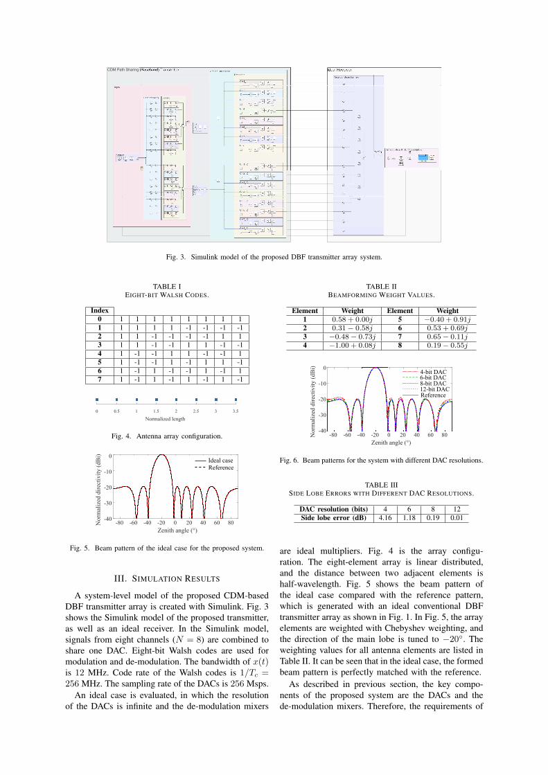
Fig. 3. Simulink model of the proposed DBF transmitter array system.
TABLE IEIGHT-BIT WALSH CODES.
Index0 1 1 1 1 1 1 1 11 1 1 1 1 -1 -1 -1 -12 1 1 -1 -1 -1 -1 1 13 1 1 -1 -1 1 1 -1 -14 1 -1 -1 1 1 -1 -1 15 1 -1 -1 1 -1 1 1 -16 1 -1 1 -1 -1 1 -1 17 1 -1 1 -1 1 -1 1 -1
0 0.5 1 1.5 2 2.5 3 3.5
Normalized length
Fig. 4. Antenna array configuration.
-80 -60 -40 -20 0 20 40 60 80
Zenith angle (°)
-40
-30
-20
-10
0
Norm
aliz
ed d
irec
tivit
y (
dB
i)
Ideal case
Reference
Fig. 5. Beam pattern of the ideal case for the proposed system.
III. SIMULATION RESULTS
A system-level model of the proposed CDM-basedDBF transmitter array is created with Simulink. Fig. 3shows the Simulink model of the proposed transmitter,as well as an ideal receiver. In the Simulink model,signals from eight channels (N = 8) are combined toshare one DAC. Eight-bit Walsh codes are used formodulation and de-modulation. The bandwidth of x(t)is 12 MHz. Code rate of the Walsh codes is 1/Tc =256 MHz. The sampling rate of the DACs is 256 Msps.
An ideal case is evaluated, in which the resolutionof the DACs is infinite and the de-modulation mixers
TABLE IIBEAMFORMING WEIGHT VALUES.
Element Weight Element Weight1 0.58 + 0.00j 5 −0.40 + 0.91j2 0.31− 0.58j 6 0.53 + 0.69j3 −0.48− 0.73j 7 0.65− 0.11j4 −1.00 + 0.08j 8 0.19− 0.55j
-40
-30
-20
-10
0
Norm
aliz
ed d
irec
tivit
y (
dB
i)
-80 -60 -40 -20 0 20 40 60 80
Zenith angle (°)
4-bit DAC6-bit DAC8-bit DAC12-bit DACReference
Fig. 6. Beam patterns for the system with different DAC resolutions.
TABLE IIISIDE LOBE ERRORS WITH DIFFERENT DAC RESOLUTIONS.
DAC resolution (bits) 4 6 8 12Side lobe error (dB) 4.16 1.18 0.19 0.01
are ideal multipliers. Fig. 4 is the array configu-ration. The eight-element array is linear distributed,and the distance between two adjacent elements ishalf-wavelength. Fig. 5 shows the beam pattern ofthe ideal case compared with the reference pattern,which is generated with an ideal conventional DBFtransmitter array as shown in Fig. 1. In Fig. 5, the arrayelements are weighted with Chebyshev weighting, andthe direction of the main lobe is tuned to −20◦. Theweighting values for all antenna elements are listed inTable II. It can be seen that in the ideal case, the formedbeam pattern is perfectly matched with the reference.
As described in previous section, the key compo-nents of the proposed system are the DACs and thede-modulation mixers. Therefore, the requirements of

-40
-35
-30
-25
-20
4 6 8 10 12 14
DAC resolution (bits)
EV
M (
dB
)
Fig. 7. EVM of systems with different DAC resolutions in 64QAM.
-40
-30
-20
-10
0
Norm
aliz
ed d
irec
tivit
y (
dB
i)
-80 -60 -40 -20 0 20 40 60 80
Zenith angle (°)
Reference
0 dBm P1dB6 dBm P1dB12 dBm P1dB
Fig. 8. Beam patterns with different P1dB values of mixers.
TABLE IVSIDE LOBE ERRORS WITH DIFFERENT P1DB VALUES.
P1dB (dBm) 0 3 6 9 12 15Side lobe error (dB) 4.36 2.66 1.47 0.77 0.38 0.25
-40
-35
-30
-25
-20
EV
M (
dB
)
0 3 6 9 12 15
P1dB (dBm)
Fig. 9. EVM of different P1dB values in 64-QAM.
these two components are evaluated in the simulation.Fig. 6 shows the beam patterns for systems withdifferent DAC resolutions, all with the same antennaweightings as shown in Table II. The main lobes of thepatterns with different DAC resolutions varies slightly.The side lobes errors of the beamforming patterns arelisted in Table III. When the resolution is 8-bit orhigher, the side lobes errors are smaller than 0.2 dBcompared with the reference.
In Fig. 7, the error vector magnitude (EVM) of thetransmitted signal is calculated with different DACresolutions. The modulation method used for x(t) is64-QAM. The EVM reaches to the minimal at 8-bitDAC resolution.
Another simulation is performed to evaluate therequirements for the de-modulation mixers. The effectsof different input 1 dB Gain Compression (P1dB)values of the mixers are evaluated. Fig. 8 illustrates thebeam patterns with different input P1dB of the mixers.In the simulation, the input power of the mixers is
0 dBm and the resolution of the DACs is 8 bits. Themain lobes of the beam patterns fit the reference verywell with different P1dB values. The side lobe errorsare below 1 dB as long as the P1dB is larger than9 dBm.
The EVMs of the transmitted are also calculatedwith different P1dB values. Fig. 9 shows the EVMresults of 64QAM. The EVM is below −35 dB whenP1dB is larger than 12 dBm. In hardware implementa-tion, passive mixers can be used to achieve high P1dB.
IV. CONCLUSION
In this paper, a method to reduce the hardware fora DBF transmitter array system has been proposed.By using code-division multiplexing technique, signalsfrom different channels are combined together, whichsignificantly reduce the required number of DACs, ascompared with a conventional DBF transmitter arraysystem. After the DAC, signals of different channelsare separated through a de-modulation process. Designprinciple of the proposed code-modulation for hard-ware reduction in a digital beamforming transmittersystem has been described; a system-level simulationhas been performed to verify the performance; resultsshow that the beamforming accuracy and signal qualitycan be maintained with reduced number of DACs inthe proposed system.
REFERENCES
[1] H. J. Visser, Array and phased array antenna basics. Chichester,U.K.: Wiley, 2006.
[2] S. Denno and T. Ohira, “Modified constant modulus algorithmfor digital signal processing adaptive antennas with microwaveanalog beamforming,” IEEE Trans. Antennas Propag., vol. 50,no. 6, pp. 850–857, Jun. 2002.
[3] I. Chiba, R. Miura, T. Tanaka, and Y. Karasawa, “Digital beamforming (DBF) antenna system for mobile communications,”IEEE Aerosp. Electron. Syst. Mag., vol. 12, no. 9, pp. 31–41,Sep. 1997.
[4] Z. Peng, J. Chen, Y. Dong, B. Zhang, S. Qiao, D. Ye, J. Huangfu,Y. Sun, C. Li, and L. Ran, “Radio frequency beamforming basedon a complex domain frontend,” IEEE Trans. Microw. TheoryTech., vol. 64, no. 1, pp. 289–298, Jan. 2016.
[5] A. Matsuzawa, “Trends in high speed ADC design,” in Proc.IEEE 7th Int. Conf. ASIC (ASICON), Guilin, China, 2007, pp.245–248.
[6] J. D. Fredrick, Y. Wang, and T. Itoh, “Smart antennas basedon spatial multiplexing of local elements (SMILE) for mutualcoupling reduction,” IEEE Trans. Antennas Propag., vol. 52, no.1, pp. 106–114, Jan. 2004.
[7] E. A. Alwan, S. B. Venkatakrishnan, A. A. Akhiyat, W. Khalil,and J. L. Volakis, “Code optimization for a code-modulated RFfront end,” IEEE Access, vol. 3, pp. 260–273, 2015.
[8] S. B. Venkatakrishnan, D. K. Papantonis, A. A. Akhiyat,E. A. Alwan, and J. L. Volakis, “Experimental validation ofon-site coding digital beamformer with ultra-wideband antennaarrays,” IEEE Trans. Microw. Theory Tech., pp. 1–10, Sep. 2017.
[9] E. A. Alwan, S. B. Venkatakrishnan, A. A. Akhiyat, W. Khalil,and J. L. Volakis, “Phase error evaluation in a two-path receiverfront-end with on-site coding,” IEEE Access, vol. 3, pp. 55–63,2015.