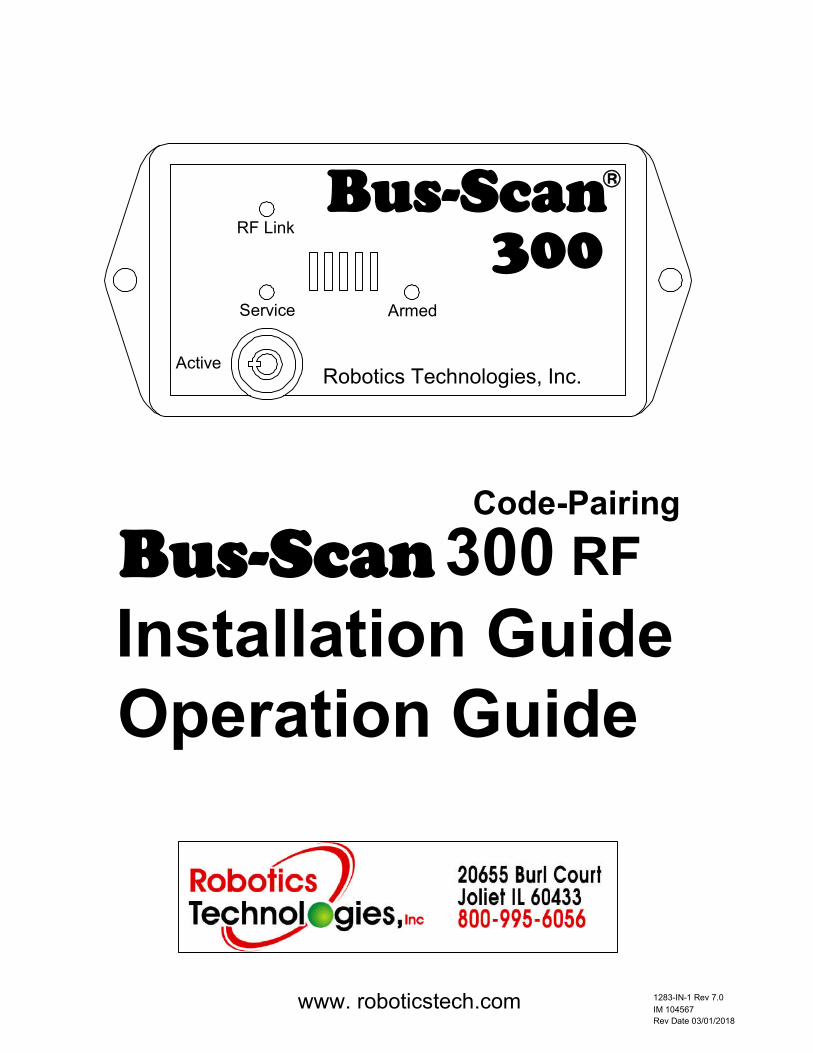
code-pairing bus-scan300 installation guide operation guide
TRANSCRIPT
1283-IN-1 Rev 7.0
IM 104567
Rev Date 03/01/2018
www. roboticstech.com
Bus-Scan Installation GuideOperation Guide
b
Robotics Technologies, Inc.
Armed
Active
Service
RF Link
300Bus-Scan
300 RFCode-Pairing
2
For Warranty Service, call Robotics Technologies, Inc. Customer Service
to obtain an RMA (Return Materials Authorization), and then return the
product postage prepaid to Robotics Technologies, Inc. The RMA number
should be written clearly on the outside of the box. Please enclose a brief
explanation of the problem, so that we can more efficiently diagnose your
item and ensure timely service.
Return Policy
For support, please contact Robotics Technologies, Inc. or a
Robotics Technologies Authorized Dealer.
Robotics Technologies, Inc.
20655 Burl Court
Jolliet, IL 60433
Phone (800) 995-6056
Fax (815) 722-7655
Website: www.roboticstech.com
Contact Information
Table of Contents
2 Return Policy and Contact Information
3 Supplied Components
4 Bus-Scan 300 Features and Functions
5 Bus-Scan 300 System Operation
6 Required Tool and Installation Instructions
7 Installation Instructions and System Testing
8 Bus-Scan 300 Wiring Instructions
9 Troubleshooting
10 RF Receiver / Transmitter
11 Specifications and Replacement Parts
12 Warranty

7
3
6
43
21
The following components are included with the Bus-Scan 300
1 Bus-Scan 300 Control Unit
2 Remote transmitter
3 # 8 x 3/8" sheet metal screws (4)
4 Service override key
5 Wiring harness
6 Bus-Scan 300 installation and operations guide
7 Drilling template
Supplied Components
Bus-Scan300
RF Link
Service
Active
Armed
Robotics Technologies, Inc.
b
5
BS 100TX Drilling Template
Bus-Scan 300 Drilling Template
Bus-Scan300
RF Link
Service
Active
Armed
Robotics Technologies, Inc.
b
RoboticsTechnologies, Inc
Bus-Scan 300 RFInstallation GuideOperation Guide
Joliet, IL Made in U.S.A
www. roboticstech.com 1283-IN-1 Rev 1.0
IM 104567
Rev Date 9/28/2009

4
876
42
Bus-Scan300
RF Link
Service
Active
Armed
Robotics Technologies, Inc.
b
1 2 3
ON
1 Service Switch
Deactivates the Bus-Scan 300. This feature is used when the vehicle
is being serviced. The key can be removed in both the Active or
Service positions
2 Service indicator light
Blinks when the Bus-Scan 300 is in the service mode
3 RF Link indicator light
Lights when the coded signal is received from the Bus-Scan
Transmitter
4 Armed indicator light
Lights when the system is armed
5 Transmitter-Receiver Pairing Hole
Used to match the transmitter and receiver codes
6 Option Select Switches
Selects different time-out lengths and controls the operation the RF
receiver
7 Main Harness Receptacle
8 Optional Siren Receptacle
1
3
Bus-Scan 300 Features and Functions
5
5
Bus-Scan 300 System Operation
The Bus-Scan 300 system operates in the following sequence:
1) The bus is started, and the route begins.
2) After the route is completed and the bus is turned off, the Bus-Scan 300 emits a
reminder tone.
3) The driver proceeds to the rear of the bus, checking for sleeping children.
4) The driver pushes the deactivation push-button.
5) The Bus-Scan 300 is deactivated.
6) The driver exits the vehicle. If the driver exits the vehicle without deactivating the
Bus-Scan 300, the horn will sound after the preset time-out. (Alarm Condition).
The Bus-Scan 300 can be armed in 3 different ways:
1) Classic Mode: The Bus-Scan 300 will activate on every ignition cycle. To use this
mode, connect the Blue wire to a constant 12v source.
2) Stop Arm Mode: The Bus-Scan 300 will arm only after the stop arm circuit has been
activated. To use this mode, connect the Blue wire to the Stop Arm Circuit and set the
option DIP switch #3 to Off.
3) Stop Arm Mode with Field Trip Timer: The Bus-Scan 300 will arm after the stop arm
circuit has been activated, or the bus has been running for 10 minutes. To use this
mode, connect the Blue wire to the Stop Arm Circuit and set the option DIP switch #3 to
On.
To Cancel the Alarm
1) The driver must cycle the Ignition off, to on, to off.
2) The driver must follow the proper deactivating sequence (steps 3-6 above)
The Bus-Scan 300 is equipped with a tamper feature that will alarm if the deactivation
push-button is tampered with.
A tamper condition exists if the deactivation push-button is activated
during the cycling of the ignition from on to off.
To Cancel the Tamper Alarm
1) The Tamper condition must be removed
2) The driver must cycle the Ignition off to on to off
3) The driver must follow the proper deactivating sequence (steps 3-6 above)
2
6
7
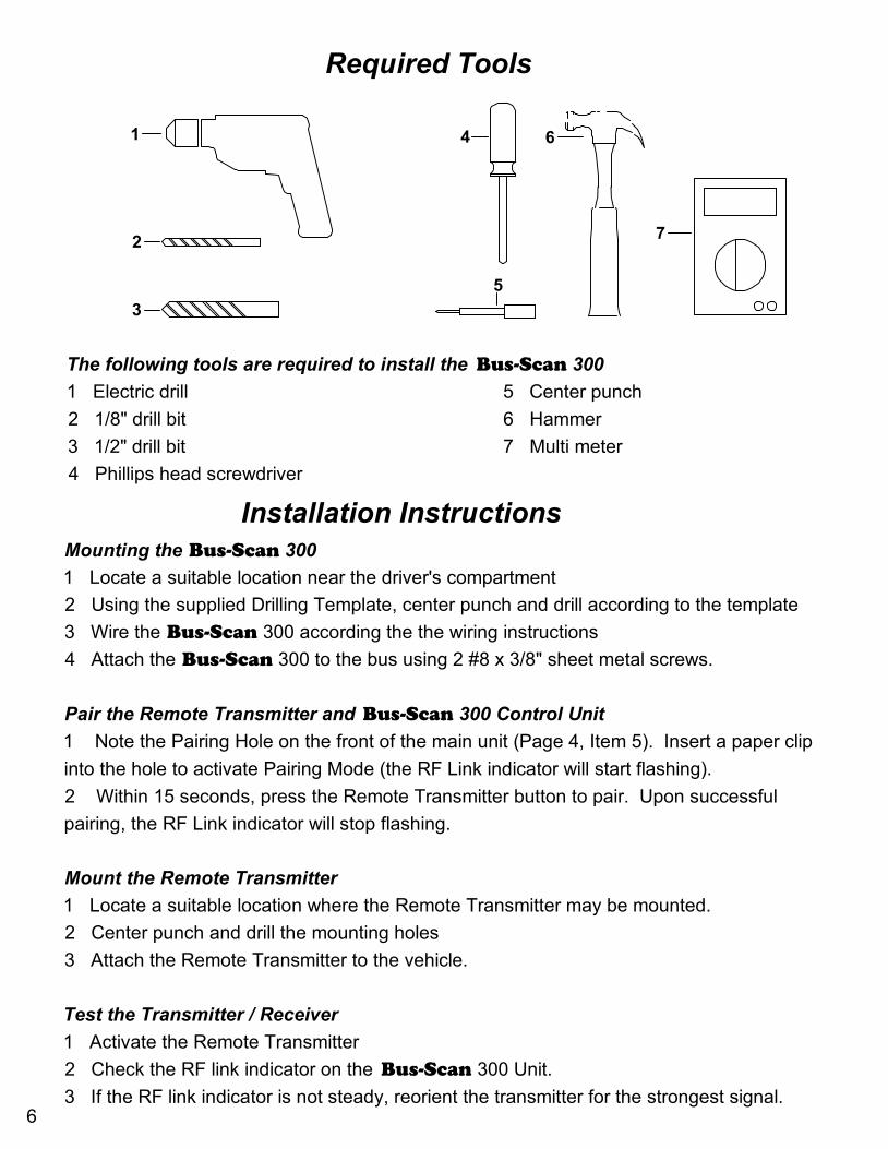
The following tools are required to install the Bus-Scan 300
1 Electric drill 5 Center punch
2 1/8" drill bit 6 Hammer
3 1/2" drill bit 7 Multi meter
4 Phillips head screwdriver
5
64
3
1
Required Tools
Installation InstructionsMounting the Bus-Scan 300
1 Locate a suitable location near the driver's compartment
2 Using the supplied Drilling Template, center punch and drill according to the template
3 Wire the Bus-Scan 300 according the the wiring instructions
4 Attach the Bus-Scan 300 to the bus using 2 #8 x 3/8" sheet metal screws.
Pair the Remote Transmitter and Bus-Scan 300 Control Unit
1 Note the Pairing Hole on the front of the main unit (Page 4, Item 5). Insert a paper clip
into the hole to activate Pairing Mode (the RF Link indicator will start flashing).
2 Within 15 seconds, press the Remote Transmitter button to pair. Upon successful
pairing, the RF Link indicator will stop flashing.
Mount the Remote Transmitter
1 Locate a suitable location where the Remote Transmitter may be mounted.
2 Center punch and drill the mounting holes
3 Attach the Remote Transmitter to the vehicle.
Test the Transmitter / Receiver
1 Activate the Remote Transmitter
2 Check the RF link indicator on the Bus-Scan 300 Unit.
3 If the RF link indicator is not steady, reorient the transmitter for the strongest signal.
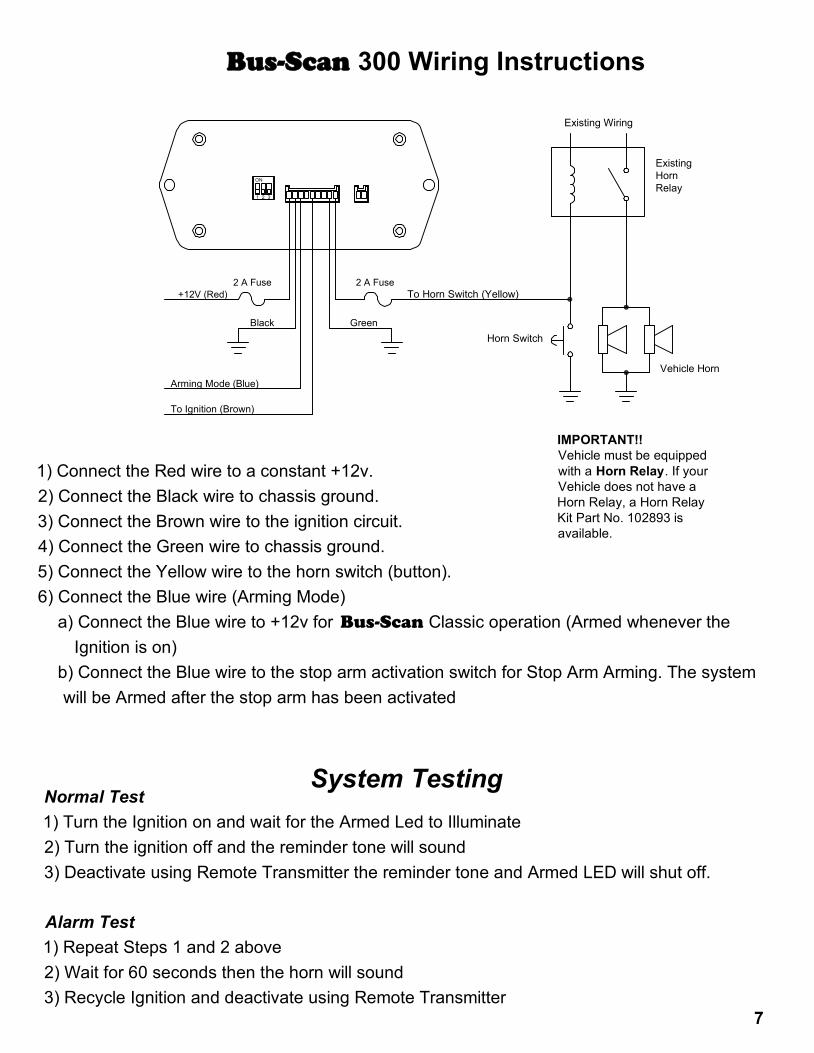
Bus-Scan 300 Wiring Instructions
1) Connect the Red wire to a constant +12v.
2) Connect the Black wire to chassis ground.
3) Connect the Brown wire to the ignition circuit.
4) Connect the Green wire to chassis ground.
5) Connect the Yellow wire to the horn switch (button).
6) Connect the Blue wire (Arming Mode)
a) Connect the Blue wire to +12v for Bus-Scan Classic operation (Armed whenever the
Ignition is on)
b) Connect the Blue wire to the stop arm activation switch for Stop Arm Arming. The system
will be Armed after the stop arm has been activated
+12V (Red)2 A Fuse
1 2 3
ON
Vehicle Horn
Horn Switch
IMPORTANT!!Vehicle must be equipped with a Horn Relay. If your Vehicle does not have a Horn Relay, a Horn Relay Kit Part No. 102893 is available.
To Horn Switch (Yellow)
Existing Wiring
Existing HornRelay
Black Green
Arming Mode (Blue)
2 A Fuse
Normal Test
1) Turn the Ignition on and wait for the Armed Led to Illuminate
2) Turn the ignition off and the reminder tone will sound
3) Deactivate using Remote Transmitter the reminder tone and Armed LED will shut off.
Alarm Test
1) Repeat Steps 1 and 2 above
2) Wait for 60 seconds then the horn will sound
3) Recycle Ignition and deactivate using Remote Transmitter
System Testing
7
To Ignition (Brown)

8
Troubleshooting
Reminder tone not sounding after ignition on/off cycle
1 Check Red wire for a constant +12v
2 Check Brown wire
a) +12v when Ignition is on
b) 0v when ignition is off
3 An arming mode other than Classic has been selected:
a) The Blue wire is disconnected
b) The Blue wire is connected to the stop arm control (Stop Arm Arming)
Armed System Disarms after Ignition Cycle
1 A power interruption or brown out power condition occurred
a) Connect the Red wire to another 12v power source
Horn Sounds when ignition is turned off
1 Tamper Condition.
a) Remote Transmitter button pushed during ignition cycling.
Remote Transmitter will not deactivate the system
1 Transmitter battery may need replacement.
2 Reorient the transmitter for a "clear path" to the receiver.
3 Ensure that the transmitter and receiver are paired.
Alarm will not sound horn
1 Horn Switch Wire (Yellow) improperly wired.
2 Horn Switch Wire (Yellow) Fuse open.
3 Horn Ground Wire (Green) improperly wired.
Horn Switch Fuse Blows
1 Vehicle does not have a Horn Relay.
a) Install Horn Relay Kit Part No. 102893.
2 Horn Switch Wire (Yellow) improperly wired.
9
Reminder Tone Sounds 5 times whenever the vehicle is turned on
This is normal when the Bus-Scan 300 is in Service Mode. The
beeps remind the driver that the Bus-Scan 300 is in Service
Mode.
The range of the keyless entry system decreased
1 The Bus-Scan and the vehicle are both using the 315Mhz Frequency.
a) Locate the Option DIP Switch (3 Position Switch) on the back
of the Bus-Scan 300. Refer to the diagram and chart below
b) Slide switch #3 on the to the ON position.
Note the RF Link will only be active during the
Bus-Scan Time-Out
I want a longer or shorter Time-Out
The Bus-Scan 300 can be set for a 1 or 5 minute delay.
1 To change the delay
a) Locate the Option DIP Switch (3 Position Switch) on the back
of the Bus-Scan 300
b) Slide switch #1 to the desired value.
Off=1 Minute On=5 Minutes
Troubleshooting Continued
To change the time-out delay and receiver option, change the DIP
switch settings according to the chart
Bus-Scan 300 Option Setting
ON
321
ON
321
Time-Out Auto Arming
1 Minute
5 MinutesOn
Off No Auto ArmingOff
On 10 Minute
Auto Arming
Remote Option
Full Time SensingOff
Sensing During
Time-Out Only
On
1 2 3
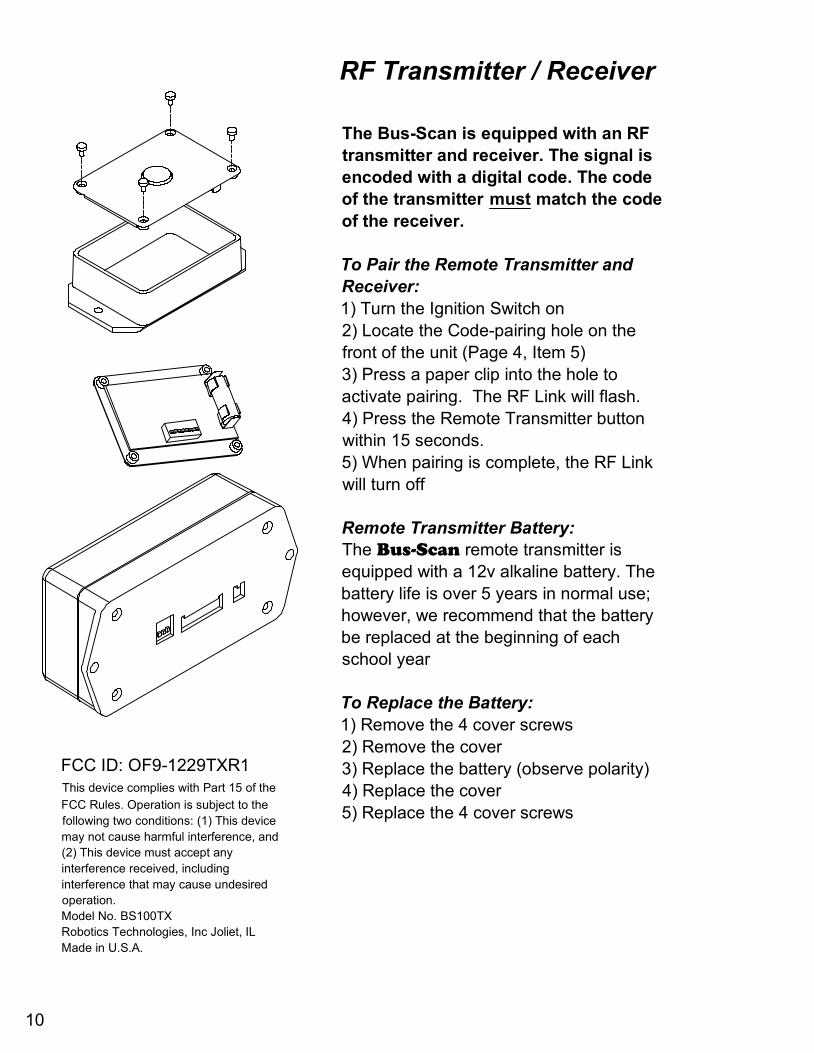
The Bus-Scan is equipped with an RF
transmitter and receiver. The signal is
encoded with a digital code. The code
of the transmitter must match the code
of the receiver.
To Pair the Remote Transmitter and
Receiver:
1) Turn the Ignition Switch on
2) Locate the Code-pairing hole on the
front of the unit (Page 4, Item 5)
3) Press a paper clip into the hole to
activate pairing. The RF Link will flash.
4) Press the Remote Transmitter button
within 15 seconds.
5) When pairing is complete, the RF Link
will turn off
Remote Transmitter Battery:
The Bus-Scan remote transmitter is
equipped with a 12v alkaline battery. The
battery life is over 5 years in normal use;
however, we recommend that the battery
be replaced at the beginning of each
school year
To Replace the Battery:
1) Remove the 4 cover screws
2) Remove the cover
3) Replace the battery (observe polarity)
4) Replace the cover
5) Replace the 4 cover screws
FCC ID: OF9-1229TXR1This device complies with Part 15 of the
FCC Rules. Operation is subject to the
following two conditions: (1) This device
may not cause harmful interference, and
(2) This device must accept any
interference received, including
interference that may cause undesired
operation.
Model No. BS100TX
Robotics Technologies, Inc Joliet, IL
Made in U.S.A.
RF Transmitter / Receiver
10
11
Bus-Scan 300 Control Unit
Dimensions: Length 4.25" Width 2.25" Height 1.5"
Enclosure Material: Flame Retardant ABS Plastic UL 94-5VA
Electrical System: 12v Negative Ground Fuse @ 2A
Horn Activation: Form A Contact Fuse @ 2 Amp
RF Receiver: 315 Mhz ASK
BS 100TX Remote Transmitter
Dimensions: Length 4.25" Width 2.375" Height 1.0"
Enclosure Material: Flame Retardant ABS Plastic UL 94-5VA
Battery: 12v Alkaline Battery MN21A, GP23A or equivalent
Frequency: 315 Mhz ASK
Specifications
Replacement Parts and Accessories
Part No. Description
106029 Bus-Scan 300 RF Coded Control Unit
106032 Bus-Scan BS 100TX Coded Remote Transmitter
103553 12v Alkaline Battery
104546 Bus-Scan RF Wiring Harness
103543 Bus-Scan Service Switch Lock
102799 Bus-Scan Service Switch Key
104569 Bus-Scan 300 RF Parts Kit
104567 Bus-Scan 300 RF Installation and Operations Guide
102893 Bus-Scan Horn Relay Kit
104533 Bus-Scan Siren
104078 Bus-Scan Light Cotrol Module
104186 Bus-Scan Light Cotrol Module for Thomas C2
12
Robotics Technologies, Inc. (RTI) warrants its products to be free from defects in
materials and workmanship for a period of one (1) year from the date of
purchase. Its obligation under this warranty is limited to repairing or replacing at
its own sole option any such defective products. To obtain service under this
warranty you must obtain a Return Material Authorization (RMA) number from
RTI. Products must be returned to RTI with transportation charges prepaid and
must be accompanied by a brief description of the problem encountered and
proof of date and place of purchase. This warranty does not apply to equipment
that has been damaged by accident, negligence or misapplication or has been
altered or modified in any way. This warranty applies only to the original
purchaser.
The Bus-Scan® Seat Check Reminder is not a security or detection device. It is
used as a reminder for the driver to physically check seats.
It is the responsibility of the customer to ensure secure mounting and the
continued maintenance thereof. Customer will indemnify RTI and hold it
harmless from all actions or litigation arising from misuse of or improper
mounting of the Bus-Scan®.
EXCEPT AS PROVIDED HEREIN RTI MAKES NO WARRANTIES, EXPRESS
OR IMPLIED, INCLUDING WARRANTIES OF MERCHANTABILITY AND
FITNESS FOR A PARTICULAR PURPOSE. Some states do not permit
limitation or exclusion of implied warranties; therefore the aforesaid limitations(s)
or exclusion(s) may not apply to purchaser.
EXCEPT AS PROVIDED ABOVE, IN NO EVENT WILL RTI BE LIABLE FOR
DIRECT, INDIRECT, SPECIAL, INCIDENTAL, OR CONSEQUENTIAL
DAMAGES ARISING OUT OF THE USE OF THIS PRODUCT EVEN IF
ADVISED OF THE POSSIBILITY OF SUCH DAMAGE. Specifically, RTI is not
liable for any costs such as loss of profits or revenue, loss of service, loss of
equipment, costs of substitutes, and claims by third parties or otherwise. This
warranty gives you specific legal rights and you may also have other rights that
vary from state to state.
Warranty