code reader fq-cr series - · pdf filecode reader fq-cr series ... 10 the flexibly ... the...
TRANSCRIPT
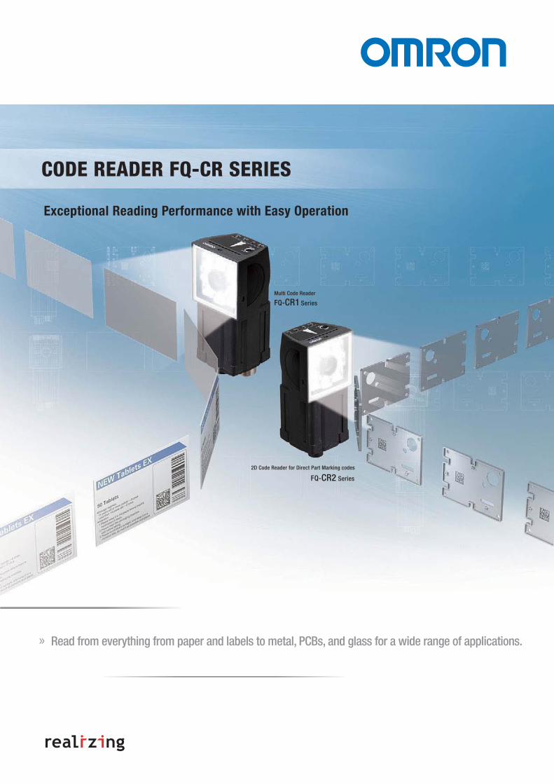
» Read from everything from paper and labels to metal, PCBs, and glass for a wide range of applications.
CODE READER FQ-CR SERIES
Exceptional Reading Performance with Easy Operation
Series
Multi Code Reader
FQ-CR1
2D Code Reader for Direct Part Marking codes
SeriesFQ-CR2

2
Solve a variety off different applications with one product series
Read Codes Printed on Paper or Labels
Reads 14 Different Codes
Many different codes are used for different applications. And for some products, different codes are printed together.
The FQ-CR1 can read many different codes without requiring any changes to its settings.
• QR code is the registered trademark of DENSO WAVE.
��������� �������� �������������
����������� ���������������
JAN/EAN/UPC
Codebar (NW-7)QR CodeITF (Interleaved 2 of 5)
GS1-DataBarData Matrix
����� ����������
�� �!
"�������#�������$���������������% Data Matrix QR Code Micro QR Code
PDF417 Micro PDF417
��������#�������&���������������%JAN/EAN/UPC Code39 Codabar (NW-7)
ITF (Interleaved 2 of 5) Code93 Code128 / GS1-128
GS1-128 Composite Code PharmacodeGS1-DataBar
'������� �!
3
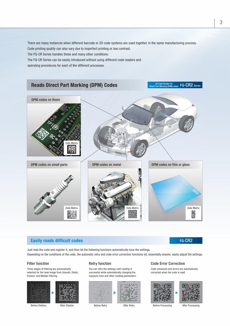
There are many instances when different barcode or 2D code systems are used together in the same manufacturing process.
Code printing quality can also vary due to imperfect printing or low contrast.
The FQ-CR Series handles these and many other conditions.
The FQ-CR Series can be easily introduced without using different code readers and
operating procedures for each of the different processes.
Easily reads difficult codes
Reads Direct Part Marking (DPM) Codes
Just read the code and register it, and then let the following functions automatically tune the settings.
Depending on the conditions of the code, the automatic retry and code error correction functions let, essentially anyone, easily adjust the settings.
Filter functionThree stages of filtering are automatically selected for the read image from Smooth, Dilate, Erosion, and Median filtering.
Code Error Correction Code omissions and errors are automatically corrected when the code is read.
Retry functionYou can retry the settings until reading is successful while automatically changing the exposure time and other reading parameters.
Before Dilation After Dilation Before Retry After Retry Before Processing After Processing
DPM codes on metal DPM codes on film or glassDPM codes on small parts
Data MatrixData Matrix Data Matrix
DPM codes on Resin
Data Matrix
2D Code Reader forDirect Part Marking (DPM) codes SeriesFQ-CR2
FQ-CR2

4
Types of Filtering
Combining Filtering
Dilate Erosion
Filter functionRemoval of Printing Irregularities or Noise
You can apply up to three of the four unique filters developed by OMRON
in the desired order to remove printing irregularities and noise, in order to achieve a stable reading.
Erosion and dilation can be combined to connect dots without changing the dot thickness.
Smooths the image.Smooth
For white codes, increases the cell size.Effective for reading codes with cell spreading.Dilate
For white codes, reduces the cell size.Effective for reading separated dot codes.Erosion
Removes noise. Median
OMRON’s Unique Algorithm Provides Superior Reading Ability for Direct Part Marking codes
FQ-CR2

5
Retrying the Specified Number of Times with the Same Conditions1
2
3
4
Reading
Retry functionAutomatic Parameter Adjustment Until Reading is Successful
Code Readers must be able to read codes even for poor printing conditions. You can automatically retry reading while changing the exposure time
and other reading conditions, even for changing workpieces or environments, to enable a stable reading.
Code Error Correction Position DisplayEasy Confirmation of Code Quality
Red circles are displayed on cells
for which the code was corrected on the display.
This clearly shows where the code quality was poor.
The following retry functions are provided.
Reading is performed the specified number of times for the same scene.
Retrying While External Trigger Is InputReading is performed until successful, as long as an external level trigger is input.
Retrying While Changing the Shutter SpeedReading is performed for the same scene while changing the exposure time in stages.
Retrying While Changing the Reading Conditions
When reading DPM codes, inconsistencies in printing conditions can result
in NGs if reading is performed with only one set of reading settings.
The FQ-CR allows you to register up to 32 sets of
reading conditions as scenes and retry reading
while changing the scenes in order.
The system automatically determines the scenes
with the highest usage rates and changes the order to start
with them to flexibly handle changes in reading conditions.
Of course you can specify a fixed order if required.
Scene 1
1ms 1.3ms 0.7ms 1.6ms
Scene 2 Scene 3
During level trigger input
N G N G O K
N G N G O K
N G N G O K
N G N GN G O K
Rapidly switch to the optimum reading conditions.Register 32 sets of reading conditions.
Scene 2
Scene 3
Scene 4
Scene 5
Scene 6
Scene 7
Scene 8
Scene 31
Scene 32
Scene 1

6
High power LEDs
Four times the brightness of previous models.
Lens and Camera
Decoder
Ethernet Output
Robust housing: IP67
simple fine tuning of camera focus.
Actual Size
Built-in HDR function.
Output read codes on Ethernet.
Cuts specular reflections.
Polarization filter
Stable Reading Functions Packed into a Compact Body
FQ-CR1 FQ-CR2

7
Detection and Connection
The wider the field of view, the more difficult it is to maintain consistent
lighting within the field, causing errors in reading. The built-in LEDs of
the FQ-CR Series use a unique OMRON DR optical system for effective
light usage to maintain consistent lighting within the field of vision at a
brightness that is four times that of previous models.
High-power LEDsReads Codes Even with Low Contrast
The HDR (high dynamic range) function minimizes the influence of
changes in lighting conditions and light reflection. This enables
stable inspections even for materials that are difficult to light evenly,
such as metal parts or glossy films, or in locations subject to external
light interference.
HDR FunctionCuts Light Interference
A polarizing filter is included to cut specular reflection from glossy
surfaces. This enables stable code reading even for metallic or other
glossy surfaces.
Polarizing FilterCuts Specular Reflections
The compact body also provides an Ethernet connector so that you
can transfer read data and images via Ethernet. Smoothly transfer
data to PLCs, computers, or other host devices.
Ethernet ConnectionCommunications with Host Devices
Ethernet
Halation Stable Detection for Metal Surfaces Subject to Gloss and Inconsistent Lighting
Previous Lighting High-power Lighting
Without Polarizing Filter With Polarizing Filter
Previous Lighting

8
Select the type of code.
You can automatically tune all of these reading conditions just by making the basic settings.
Optimum Tuning in Three Steps
Read a code.
TouchFinder for PC (Free)After purchasing the Code Reader,
you can download the TouchFinder for PC free from the member’s website.you ca
Touch Finder
Use the convenient Touch Finder
for on-site settings and control panel installations,
or use a set-up tool on a computer.
Two Set-up Tools
Setup is as easy as displaying codes on the monitor and registering settings with a simple procedure.
Then, the FQ-CR will automatically tune the settings to achieve the optimum conditions.
Essentially, Simple Enough for Anyone to Set Up
FQ-CR1 FQ-CR2
9
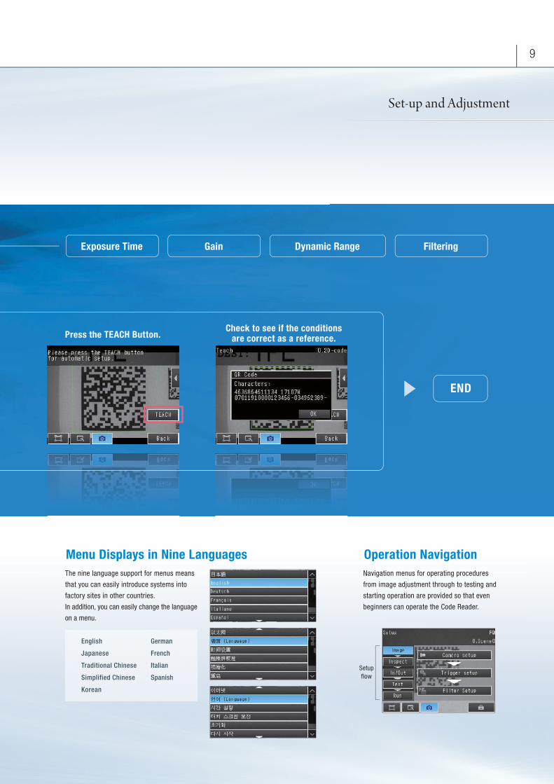
Set-up and Adjustment
The nine language support for menus means
that you can easily introduce systems into
factory sites in other countries.
In addition, you can easily change the language
on a menu.
Menu Displays in Nine LanguagesNavigation menus for operating procedures
from image adjustment through to testing and
starting operation are provided so that even
beginners can operate the Code Reader.
Operation Navigation
Press the TEACH Button.
Exposure Time
English
Japanese
Traditional Chinese
Simplified Chinese
Korean
German
French
Italian
Spanish
Check to see if the conditionsare correct as a reference.
END
Gain Dynamic Range Filtering
Setupflow

10
The flexibly arrangeable platform can be used for
simple configurations with one Code Reader for
complex configurations with multiple Code Readers
reading from different directions.
Up to eight Code Readers can be controlled from the
Touch Finder set-up console.
Connect Up To Eight Code Readers
The FQ-CR2 contains state-of-the-art algorithms that enable the reading of codes even
with poor reading quality. However, even if the code quality continues to deteriorate for
some reason, auto-correction and retrying are used to enable reading, making it
impossible to tell where quality was lost simply from the OK/NG reading information.
Here, you can use the cell recognition rate information. The cell recognition rate changes
with code printing quality, position inconsistency, installation conditions, and noise. You
can log the cell recognition rate and image together to manage quality trends. The
logging of recent results is useful for testing when commissioning a line. Run through
some sample products and log the cell recognition rate. You can then display the results
in a time-based graph to see how much leeway there is in reading performance.
* For the FQ-CR1, the number of detected characters is logged instead of the cell recognition rate.
Code Quality Management
Logging of Recent Results
File Logging
Displays the most recent 1,000cell recognition rate in graph form.
g of Recent Results
gging
SD Card
Cell recognition rateUp to 10 million measurement values or more(for a 4-GB SD card)Up to 10,000 images or more(for a 4-GB SD card)
Flexible System Configuration
FQ-CR1 FQ-CR2
11
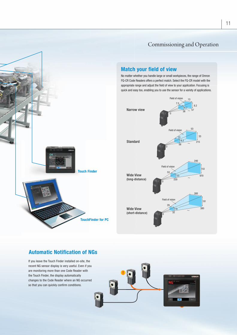
Narrow view
Standard
Wide View (long-distance)
Wide View(short-distance)
TouchFinder for PC
Touch Finder
If you leave the Touch Finder installed on-site, the
recent NG sensor display is very useful. Even if you
are monitoring more than one Code Reader with
the Touch Finder, the display automatically
changes to the Code Reader where an NG occurred
so that you can quickly confirm conditions.
Automatic Notification of NGs
No matter whether you handle large or small workpieces, the range of Omron
FQ-CR Code Readers offers a perfect match. Select the FQ-CR model with the
appropriate range and adjust the field of view to your application. Focusing is
quick and easy too, enabling you to use the sensor for a variety of applications.
Match your field of view
!
Field of vision 13
8.2
3857
0
7.5
4.7
Field of vision 53
33
21556
0
138.2
Field of vision
5333
0220
970
153
240
Field of vision
29
032
18 380
300
191
Commissioning and Operation

12 System Configuration
Connections for One Code ReaderControl by parallel input/output Control by Ethernet
Connections for Multiple Code ReaderControl by parallel input/output Control by Ethernet
Note: If you register as a member after purchasing a Code Reader, you can download the free set-up software TouchFinder for PC that runs on a PC and can be used in place of the Touch Finder. Refer to the member registration sheet for details.
Ordering InformationCode Reader (Unit: mm)
Note: Tolerance (field of vision): ±10% max.
Touch Finder
Note: AC Adapter and Battery are sold separately.
Cables (Robot cable)
Industrial Switching Hubs (Recommended)
Accessories
*1. A mounting Bracket with improved resistance to vibrations and other external stresses that cause displacement of the optical axis and field of view.
*2. The Battery uses a lithium ion secondary battery. Confirm any applicable laws and regulations in the destination country if you export the Battery.
FQ-CRCode Reader
FQ-CR Ethernet Cables
Sensor trigger
PLC
Power Supply 24 VDC
I/O Cables
Touch Finder FQ-CRCode ReaderTouch Finder
PLC
FQ-CR Ethernet Cables I/O Cables
Standard Ethernet Cables(RJ-45 of the FCC regulations)
Standard Ethernet Cables(RJ-45 of the FCC regulations)
SwitchingHub
Sensor trigger
Power Supply 24 VDC
Up to 32 Code Reader can be connected.
Touch Finder SwitchingHub
FQ-CR Ethernet Cables
Connect the triggersensor, power supplyto each Code Reader.
Standard Ethernet Cables(RJ-45 of the FCC regulations)
Up to 32 Code Reader can be connected.
Touch Finder SwitchingHub
Standard Ethernet Cables(RJ-45 of the FCC regulations)
PLC
FQ-CR Ethernet Cables
Standard Ethernet Cables(RJ-45 of the FCC regulations)
Connect the triggersensor, power supplyto each Code Reader.
Narrow View Standard Wide View(Long-distance) (Short-distance)
2D Code Reader
Multi Code Reader
NPN FQ-CR20010F-M FQ-CR10010F-MPNP FQ-CR25010F-M FQ-CR15010F-M
38 57
7.513
8.2
0
4.7
Field of vision
to
2D Code Reader
Multi Code Reader
NPN FQ-CR20050F-M FQ-CR10050F-MPNP FQ-CR25050F-M FQ-CR15050F-M
056
215
13
53
8.2
33
to
Field of vision
2D Code Reader
Multi Code Reader
NPN FQ-CR20100F-M FQ-CR10100F-MPNP FQ-CR25100F-M FQ-CR15100F-M
0220
97053
240
33
153
to
Field of vision
2D Code Reader
Multi Code Reader
NPN FQ-CR20100N-M FQ-CR10100N-MPNP FQ-CR25100N-M FQ-CR15100N-M
032
38029
300
18
191
to
Field of vision
Type Model
DC power supply FQ2-D30
AC/DC/battery FQ2-D31 (See note.)
Type Cable length Model
FQ Ethernet Cables (connect Code Reader to Touch Finder, Code Reader to PC)
2 m FQ-WN00210 m FQ-WN010
20 m FQ-WN020
I/O Cables
2 m FQ-WD00210 m FQ-WD010
20 m FQ-WD020
Appearance Number of ports
Failure detection
Current consumption Model
3 None 0.22 A W4S1-03B
5None
0.22 AW4S1-05B
Supported W4S1-05C
Application Appearance Name Model
For Code Reader
Mounting Bracket (enclosed with Code Reader) FQ-XL
Mounting Bracket for highprecision sensing *1(sold separately)
FQ-XL2
Polarizing Filter Attachment (enclosed with Code Reader) FQ-XF1
For Touch Finder
Panel Mounting Adapter FQ-XPM
AC Adapter (for models for DC/AC/Battery) FQ-AC1
Battery *2(for models for DC/AC/Battery) FQ-BAT1
Touch Pen (enclosed with Touch Finder) FQ-XT
Strap FQ-XH
SD Card (2 GB) HMC-SD291
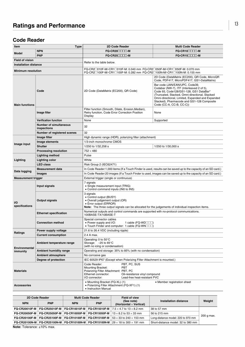
13Ratings and Performance
Code Reader
Note: Tolerance: ±10% max.
Item Type 2D Code Reader Multi Code Reader
ModelNPN FQ-CR20@@@@-M FQ-CR10@@@@-M
PNP FQ-CR25@@@@-M FQ-CR15@@@@-M
Field of visionRefer to the table below.
Installation distance
Minimum resolution FQ-CR2@010F-M/-CR1@010F-M: 0.040 mm FQ-CR2@050F-M/-CR1@050F-M: 0.070 mmFQ-CR2@100F-M/-CR1@100F-M: 0.282 mm FQ-CR2@100N-M/-CR1@100N-M: 0.155 mm
Main functions
Code 2D Code (DataMatrix (EC200), QR Code)
2D Code (DataMatrix (EC200), QR Code, MicroQR Code, PDF417, MicroPDF417, GS1-DataMatrix)
Bar code (JAN/EAN/UPC, Code39, Codabar (NW-7), ITF (Interleaved 2 of 5), Code 93, Code128/GS1-128, GS1 DataBar* (Truncated, Stacked, Omni-directional, Stacked Omni-directional, Limited, Expanded and Expanded Stacked), Pharmacode and GS1-128 Composite Code (CC-A, CC-B, CC-C))
Image filterFilter function (Smooth, Dilate, Erosion,Median), Retry function, Code Error Correction Position Display
None
Verification function None Supported
Number of simultaneous inspections 32
Number of registered scenes 32
Image input
Image filter High dynamic range (HDR), polarizing filter (attachment)
Image elements 1/3-inch monochrome CMOS
Shutter 1/250 to 1/32,258 s 1/250 to 1/30,000 s
Processing resolution 752 × 480
Lighting
Lighting method Pulse
Lighting color White
LED class Risk Group 2 (IEC62471)
Data loggingMeasurement data In Code Reader:1,000 items (If a Touch Finder is used, results can be saved up to the capacity of an SD card.)
Images In Code Reader:20 images (If a Touch Finder is used, images can be saved up to the capacity of an SD card.)
Measurement trigger External trigger (single or continuous)
I/O specifications
Input signals7 signals• Single measurement input (TRIG)• Control command inputs (IN0 to IN5)
Output signals
3 signals• Control output (BUSY)• Overall judgement output (OR)• Error output (ERROR)
Note: The three output signals can be allocated for the judgements of individual inspection items.
Ethernet specification Numerical outputs and control commands are supported with no-protocol communications.100BASE-TX/10BASE-T
Connection methodSpecial connector cables• Power supply and I/O: 1 cable (FQ-WD@@@)• Touch Finder and computer: 1 cable (FQ-WN@@@)
RatingsPower supply voltage 21.6 to 26.4 VDC (including ripple)
Current consumption 2.4 A max.
Environmental immunity
Ambient temperature rangeOperating: 0 to 50°CStorage: −25 to 65°C(with no icing or condensation)
Ambient humidity range Operating and storage: 35% to 85% (with no condensation)
Ambient atmosphere No corrosive gas
Degree of protection IEC 60529 IP67 (Except when Polarizing Filter Attachment is mounted.)
Materials
Code Reader: PBT, PC, SUSMounting Bracket: PBTPolarizing Filter Attachment: PBT, PCEthernet connector: Oil-resistance vinyl compoundI/O connector: Lead-free heat-resistant PVC
Accessories• Mounting Bracket (FQ-XL) (1)• Polarizing Filter Attachment (FQ-XF1) (1)• Instruction Manual
• Member registration sheet
2D Code Reader Multi Code Reader Field of view(See note)
(Horizontal × Vertical)Installation distance Weight
NPN PNP NPN PNP
FQ-CR20010F-M FQ-CR25010F-M FQ-CR10010F-M FQ-CR15010F-M 7.5 × 4.7 to 13 × 8.2 mm 38 to 57 mm
200 g max.FQ-CR20050F-M FQ-CR25050F-M FQ-CR10050F-M FQ-CR15050F-M 13 × 8.2 to 53 × 33 mm 56 to 215 mm
FQ-CR20100F-M FQ-CR25100F-M FQ-CR10100F-M FQ-CR15100F-M 53 × 33 to 240 × 153 mm Long-distance model: 220 to 970 mm
FQ-CR20100N-M FQ-CR25100N-M FQ-CR10100N-M FQ-CR15100N-M 29 × 18 to 300 × 191 mm Short-distance model: 32 to 380 mm

14
Touch Finder
*1. This is a guideline for the time required for the brightness to diminish to half the initial brightness at room temperature and humidity. The life of the backlight is greatly affected by the ambient temperature and humidity and will be shorter at lower or higher temperatures.
*2. This value is only a guideline. No guarantee is implied. The value will be affected by operating conditions. *3. This value is only a guideline. No guarantee is implied. The value will be affected by the operating environment and operating conditions.
Battery Specifications
Note: 1. This value is only a guideline. No guarantee is implied. The value will be affected by operating conditions2. This is a guideline for the time required for the capacity of the Battery to be reduced to 60% of the initial capacity. No guarantee is implied.
The value will be affected by the operating environment and operating conditions.
System Requirements for TouchFinder for PCThe following Personal Computer system is required to use the software.
Note: 1. The Japanese and English versions support only 32-bit OS versions.2. Available space is also required separately for data logging.
Type
Item Model
Model with DC power supply Model with AC/DC/battery power supply
FQ2-D30 FQ2-D31
Number of connectable Sensor Number of sensors that can be recognized (switched): 32 max. number or sensor that can displayed on monitor: 8 max.
Main functions
Types of measurement displays Last result display, Last NG display, trend monitor, histograms
Types of display images Through, frozen, zoom-in, and zoom-out images
Data logging Measurement results, measured images
Menu language English, German, French, Italian, Spanish, Traditional Chinese, Simplified Chinese, Korean, Japanese
Indications
LCD
Display device 3.5-inch TFT color LCD
Pixels 320 × 240
Display colors 16.7 million
Backlight
Life expectancy *1 50,000 hours at 25ºC
Brightness adjustment Provided
Screen saver Provided
Operation interface
Touch screen
Method Resistance film
Life expectancy *2 1,000,000 touch operations
External interface
Ethernet 100BASE-TX/10BASE-T
SD card SDHC-compliant, Class 4 or higher recommended
Ratings
Power supply voltage DC power connection:21.6 to 26.4 VDC (including ripple)
DC power connection: 21.6 to 26.4 VDC(including ripple)AC adapter (manufactured by Sino-American Japan Co., Ltd) connection: 100 to 240 VAC, 50/60 HzBattery connection: FQ-BAT1 Battery (1cell, 3.7 V)
Continuous operation on Battery *3 --- 1.5 h
Power consumption DC power connection: 0.2 A max. DC power connection: 0.2 A max.Charging battery: 0.4 A max.
Environmental immunity
Ambient temperature rangeOperating: 0 to 50ºCStorage: −25 to 65ºC(with no icing or condensation)
Operating: 0 to 50ºC when mounted to DIN Track or panelOperation on Battery: 0 to 40ºCStorage: −25 to 65ºC(with no icing or condensation)
Ambient humidity range Operating and storage: 35% to 85% (with no condensation)
Ambient atmosphere No corrosive gas
Vibration resistance (destruction) 10 to 150 Hz, single amplitude: 0.35 mm, X/Y/Z directions8 min each, 10 times
Shock resistance (destruction) 150 m/s2 3 times each in 6 direction (up, down, right, left, forward, and backward)
Degree of protection IEC 60529 IP20 (when SD card cover, connector cap, or harness is attached)
Weight Approx. 270 g (without Battery and hand strap attached)
Materials Case: ABS
Accessories included with Touch Finder Touch Pen (FQ-XT), Instruction Manual
Item Model FQ-BAT1
Battery type Secondary lithium ion battery
Nominal capacity 1,800 mAh
Rated voltage 3.7 V
Ambient temperature range Operating: 0 to 40ºCStorage: −25 to 65ºC (with no icing or condensation)
Ambient humidity range Operating and storage: 35% to 85% (with no condensation)
Charging method Charged in Touch Finder (FQ-D31). AC adapter (FQ-AC@) is required.
Charging time (See note 1.) 2 h
Battery backup life (See note 2.) 300 charging cycles
Weight 50 g max.
OS Microsoft Windows XP Home Edition/Professional SP2 or higher (See note 1.)Microsoft Windows 7 Home Premium or higher (See note 1.)
CPU Core 2 Duo 1.06 GHz or the equivalent or higher
RAM 1GB min.
HDD 500 MB min. available space (See note 2.)
Monitor 1,024 × 768 dots min.

15Dimensions (Unit: mm)
Code Reader (Dimensional drawings are provided here only for the products that have undergone design changes as of June 2012.)
Touch Finder
32
(108
)
9188
38(See note 2.)
(See note 1.)
Polarizing Filter Attachment
1
20±0
.1
Two, 4.5 dia.
Tightening torque: 1.2 N.m
Mounting Hole Dimensions
67
45
46
OPTICALAXIS
Mounting Bracket
3841
49
t1
8
PlateCushion
Four machine screws (double pan-head set screws)
Base
405
30
67
Optical axis
20±0
.1
38.8
20±0.159
Four-M4Depth: 6
1/4-20UNCDepth: 6
20±0.1
(108
)(6
5)
(57)
Two, 4.5 dia.
Mounting Hole Dimensions
Mounting with the FQ-XL2 Mounting BracketFQ-CRMounting with the FQ-XL Mounting Bracket
* Dimentions with the FQ-XL Mounting Bracket
Type Model Note 1. Note 2.
Narrow View,Standard
FQ-CR1@010F-M/-CR2@010F-M/-CR1@050F-M/-CR2@050F-M 11 57
Wide View FQ-CR1@100F-M/-CR2@0100F-M/-CR1@100N-M/-CR2@100N-M 3 49
44.5
33
95
70
27
10
1513.5
(See note.)
(See note.)
23.8
14
27.9
12.1
35.5
20
85
52.9
17.3
19.2
(133
.4)
(8.1)
(2)3.5
116
95
85116
31.6
(36.9)
111±1
111±
1 Panel
FQ2-D30/-D31
Note: Provided with FQ2-D31 only.
Panel Mounting Adapter
Panel Cutout Dimensions
READ AND UNDERSTAND THIS DOCUMENTPlease read and understand this document before using the products. Please consult your OMRON representative if you have any questions or comments.
WARRANTYOMRON’s exclusive warranty is that the products are free from defects in materials and workmanship for a period of one year (or other period if specified) from date ofsale by OMRON.OMRON MAKES NO WARRANTY OR REPRESENTATION, EXPRESS OR IMPLIED, REGARDING NON-INFRINGEMENT, MERCHANTABILITY, OR FITNESS FORPARTICULAR PURPOSE OF THE PRODUCTS. ANY BUYER OR USER ACKNOWLEDGES THAT THE BUYER OR USER ALONE HAS DETERMINED THAT THEPRODUCTS WILL SUITABLY MEET THE REQUIREMENTS OF THEIR INTENDED USE. OMRON DISCLAIMS ALL OTHER WARRANTIES, EXPRESS OR IMPLIED.
LIMITATIONS OF LIABILITYOMRON SHALL NOT BE RESPONSIBLE FOR SPECIAL, INDIRECT, OR CONSEQUENTIAL DAMAGES, LOSS OF PROFITS OR COMMERCIAL LOSS IN ANY WAY CONNECTEDWITH THE PRODUCTS, WHETHER SUCH CLAIM IS BASED ON CONTRACT, WARRANTY, NEGLIGENCE, OR STRICT LIABILITY.In no event shall responsibility of OMRON for any act exceed the individual price of the product on which liability is asserted.IN NO EVENT SHALL OMRON BE RESPONSIBLE FOR WARRANTY, REPAIR, OR OTHER CLAIMS REGARDING THE PRODUCTS UNLESS OMRON’SANALYSIS CONFIRMS THAT THE PRODUCTS WERE PROPERLY HANDLED, STORED, INSTALLED, AND MAINTAINED AND NOT SUBJECT TOCONTAMINATION, ABUSE, MISUSE, OR INAPPROPRIATE MODIFICATION OR REPAIR.
SUITABILITY FOR USETHE PRODUCTS CONTAINED IN THIS DOCUMENT ARE NOT SAFETY RATED. THEY ARE NOT DESIGNED OR RATED FOR ENSURING SAFETY OFPERSONS, AND SHOULD NOT BE RELIED UPON AS A SAFETY COMPONENT OR PROTECTIVE DEVICE FOR SUCH PURPOSES. Please refer to separatecatalogs for OMRON's safety rated products.OMRON shall not be responsible for conformity with any standards, codes, or regulations that apply to the combination of products in the customer’s application or useof the product.At the customer’s request, OMRON will provide applicable third party certification documents identifying ratings and limitations of use that apply to the products. Thisinformation by itself is not sufficient for a complete determination of the suitability of the products in combination with the end product, machine, system, or otherapplication or use.The following are some examples of applications for which particular attention must be given. This is not intended to be an exhaustive list of all possible uses of theproducts, nor is it intended to imply that the uses listed may be suitable for the products:• Outdoor use, uses involving potential chemical contamination or electrical interference, or conditions or uses not described in this document.• Nuclear energy control systems, combustion systems, railroad systems, aviation systems, medical equipment, amusement machines, vehicles, safety equipment,
and installations subject to separate industry or government regulations.• Systems, machines, and equipment that could present a risk to life or property.
Please know and observe all prohibitions of use applicable to the products.
NEVER USE THE PRODUCTS FOR AN APPLICATION INVOLVING SERIOUS RISK TO LIFE OR PROPERTY WITHOUT ENSURING THAT THE SYSTEM AS AWHOLE HAS BEEN DESIGNED TO ADDRESS THE RISKS, AND THAT THE OMRON PRODUCT IS PROPERLY RATED AND INSTALLED FOR THE INTENDEDUSE WITHIN THE OVERALL EQUIPMENT OR SYSTEM.
PERFORMANCE DATAPerformance data given in this document is provided as a guide for the user in determining suitability and does not constitute a warranty. It may represent the result ofOMRON’s test conditions, and the users must correlate it to actual application requirements. Actual performance is subject to the OMRON Warranty and Limitations ofLiability.
CHANGE IN SPECIFICATIONSProduct specifications and accessories may be changed at any time based on improvements and other reasons.
It is our practice to change model numbers when published ratings or features are changed, or when significant construction changes are made. However, somespecifications of the product may be changed without any notice. When in doubt, special model numbers may be assigned to fix or establish key specifications for yourapplication on your request. Please consult with your OMRON representative at any time to confirm actual specifications of purchased products.
DIMENSIONS AND WEIGHTSDimensions and weights are nominal and are not to be used for manufacturing purposes, even when tolerances are shown.
ERRORS AND OMISSIONSThe information in this document has been carefully checked and is believed to be accurate; however, no responsibility is assumed for clerical, typographical, orproofreading errors, or omissions.
PROGRAMMABLE PRODUCTSOMRON shall not be responsible for the user’s programming of a programmable product, or any consequence thereof.
COPYRIGHT AND COPY PERMISSIONThis document shall not be copied for sales or promotions without permission.
This document is protected by copyright and is intended solely for use in conjunction with the product. Please notify us before copying or reproducing this document in anymanner, for any other purpose. If copying or transmitting this document to another, please copy or transmit it in its entirety.
Note: Do not use this document to operate the Unit.
Authorized Distributor:
In the interest of product improvement, specifications are subject to change without notice.
Cat. No. Q186-E1-01 0811 (0811)
© OMRON Corporation 2011 All Rights Reserved.
OMRON Corporation Industrial Automation Company
OMRON ELECTRONICS LLCOne Commerce Drive Schaumburg,IL 60173-5302 U.S.A.Tel: (1) 847-843-7900/Fax: (1) 847-843-7787
Regional HeadquartersOMRON EUROPE B.V.Wegalaan 67-69-2132 JD HoofddorpThe NetherlandsTel: (31)2356-81-300/Fax: (31)2356-81-388
Contact: www.ia.omron.comTokyo, JAPAN
OMRON ASIA PACIFIC PTE. LTD.No. 438A Alexandra Road # 05-05/08 (Lobby 2), Alexandra Technopark, Singapore 119967Tel: (65) 6835-3011/Fax: (65) 6835-2711
OMRON (CHINA) CO., LTD.Room 2211, Bank of China Tower, 200 Yin Cheng Zhong Road, PuDong New Area, Shanghai, 200120, ChinaTel: (86) 21-5037-2222/Fax: (86) 21-5037-2200
CSM_14_1_0615