code v introductory tutorial - national cheng kung university · 7 december 2001 cheng-fang ho...
TRANSCRIPT
7 December 2001 ChengCheng--Fang Ho Fang Ho [email protected] [email protected]
1-1
OpticalOptical SystemSystem DesignDesign on Lab. of RFon Lab. of RF--MW MW PhotonicePhotonice. Phys. NCKU. Phys. NCKU
http://www.physhttp://www.phys.ncku.edu.tw.ncku.edu.tw / optics/ optics
CODE V Introductory Tutorial
CODE V CODE V Introductory TutorialIntroductory Tutorial
Cheng-Fang Ho Lab.of RF-MW Photonics,
Department of Physics, National Cheng-Kung University, Tainan, Taiwan

7 December 2001 ChengCheng--Fang Ho Fang Ho [email protected] [email protected]
1-2
OpticalOptical SystemSystem DesignDesign on Lab. of RFon Lab. of RF--MW MW PhotonicePhotonice. Phys. NCKU. Phys. NCKU
http://www.physhttp://www.phys.ncku.edu.tw.ncku.edu.tw / optics/ optics
Tutorial Outline Tutorial Outline Tutorial Outline
•• Introduction to CODE VIntroduction to CODE V•• Optical Design ProcessOptical Design Process•• Code V Design Examples :Code V Design Examples :
1.1. Digital VGA Camera Objective Digital VGA Camera Objective 2.2. 10X Microscope10X Microscope
•• Advanced Applications Advanced Applications •• ReferencesReferences
7 December 2001 ChengCheng--Fang Ho Fang Ho [email protected] [email protected]
1-3
OpticalOptical SystemSystem DesignDesign on Lab. of RFon Lab. of RF--MW MW PhotonicePhotonice. Phys. NCKU. Phys. NCKU
http://www.physhttp://www.phys.ncku.edu.tw.ncku.edu.tw / optics/ optics
Introduction to CODE VIntroduction to CODE VIntroduction to CODE V
7 December 2001 ChengCheng--Fang Ho Fang Ho [email protected] [email protected]
1-4
OpticalOptical SystemSystem DesignDesign on Lab. of RFon Lab. of RF--MW MW PhotonicePhotonice. Phys. NCKU. Phys. NCKU
http://www.physhttp://www.phys.ncku.edu.tw.ncku.edu.tw / optics/ optics
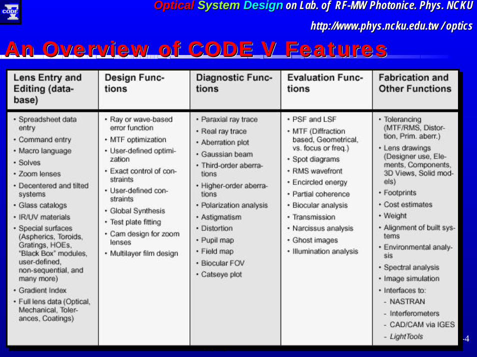
An Overview of CODE V FeaturesAn Overview of CODE V FeaturesAn Overview of CODE V Features
7 December 2001 ChengCheng--Fang Ho Fang Ho [email protected] [email protected]
1-5
OpticalOptical SystemSystem DesignDesign on Lab. of RFon Lab. of RF--MW MW PhotonicePhotonice. Phys. NCKU. Phys. NCKU
http://www.physhttp://www.phys.ncku.edu.tw.ncku.edu.tw / optics/ optics
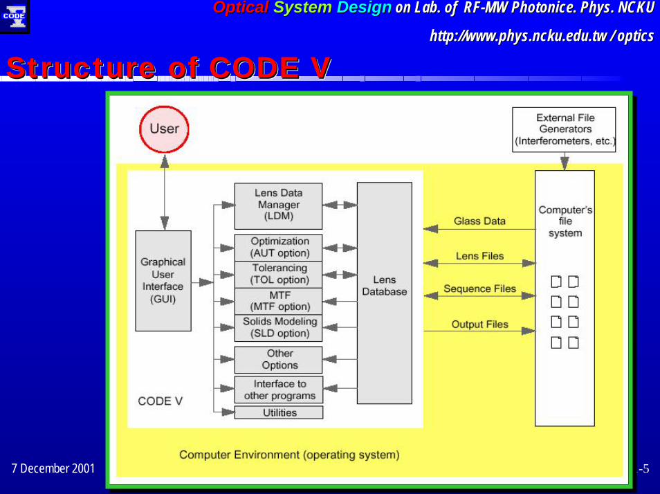
Structure of CODE VStructure of CODE VStructure of CODE V

7 December 2001 ChengCheng--Fang Ho Fang Ho [email protected] [email protected]
1-6
OpticalOptical SystemSystem DesignDesign on Lab. of RFon Lab. of RF--MW MW PhotonicePhotonice. Phys. NCKU. Phys. NCKU
http://www.physhttp://www.phys.ncku.edu.tw.ncku.edu.tw / optics/ optics
CODE V Version 9.00CODE V Version 9.00CODE V Version 9.00Menu barMenu bar
ToolbarToolbar
Lens DataLens DataManager
CommandCommandWindowWindow
Manager
Window Window NavigationNavigationBar
Error LogError Log
Bar
Status BarStatus Bar
7 December 2001 ChengCheng--Fang Ho Fang Ho [email protected] [email protected]
1-7
OpticalOptical SystemSystem DesignDesign on Lab. of RFon Lab. of RF--MW MW PhotonicePhotonice. Phys. NCKU. Phys. NCKU
http://www.physhttp://www.phys.ncku.edu.tw.ncku.edu.tw / optics/ optics
Optical Design ProcessOptical Design ProcessOptical Design Process

7 December 2001 ChengCheng--Fang Ho Fang Ho [email protected] [email protected]
1-8
OpticalOptical SystemSystem DesignDesign on Lab. of RFon Lab. of RF--MW MW PhotonicePhotonice. Phys. NCKU. Phys. NCKU
http://www.physhttp://www.phys.ncku.edu.tw.ncku.edu.tw / optics/ optics
Optical Design Flowchart Optical Design Flowchart Optical Design Flowchart •• TodayToday’’s tutorial will s tutorial will based on this process
Design condition Specificationbased on this process
Initial analysis & Performance evaluation
Optimization
Final analysis & Performance evaluation
Tolerance analysis
Pre-design
Prepare for fabrication

7 December 2001 ChengCheng--Fang Ho Fang Ho [email protected] [email protected]
1-9
OpticalOptical SystemSystem DesignDesign on Lab. of RFon Lab. of RF--MW MW PhotonicePhotonice. Phys. NCKU. Phys. NCKU
http://www.physhttp://www.phys.ncku.edu.tw.ncku.edu.tw / optics/ optics
Design Example (1):Fixed-focus VGA Digital
Camera Objective
Design Example Design Example ((11))::FixedFixed--focus VGA Digital focus VGA Digital
Camera Objective Camera Objective

7 December 2001 ChengCheng--Fang Ho Fang Ho [email protected] [email protected]
1-10
OpticalOptical SystemSystem DesignDesign on Lab. of RFon Lab. of RF--MW MW PhotonicePhotonice. Phys. NCKU. Phys. NCKU
http://www.physhttp://www.phys.ncku.edu.tw.ncku.edu.tw / optics/ optics
•• FixedFixed--focus VGA Digital Camera Objective specificationfocus VGA Digital Camera Objective specification•• Identification of a Starting PointIdentification of a Starting Point
–– FirstFirst--order optics considerationorder optics consideration
•• Selecting a Suitable Starting Point Selecting a Suitable Starting Point –– Code V New Lens WizardCode V New Lens Wizard
•• Perform a Basic AnalysisPerform a Basic Analysis–– Compare with the specifications: Spot Diagram, Aberration curvesCompare with the specifications: Spot Diagram, Aberration curves, MTF output, MTF output……....–– Guideline for OptimizationGuideline for Optimization
•• Optimization Optimization –– Make things better, Performance reMake things better, Performance re--evaluationevaluation
•• Tolerance Analysis Tolerance Analysis –– Prepare for fabricationPrepare for fabrication
•• Summary and ReferencesSummary and References
Outline Outline Outline
7 December 2001 ChengCheng--Fang Ho Fang Ho [email protected] [email protected]
1-11
OpticalOptical SystemSystem DesignDesign on Lab. of RFon Lab. of RF--MW MW PhotonicePhotonice. Phys. NCKU. Phys. NCKU
http://www.physhttp://www.phys.ncku.edu.tw.ncku.edu.tw / optics/ optics
Identification of a starting point
Identification Identification of a starting point of a starting point
7 December 2001 ChengCheng--Fang Ho Fang Ho [email protected] [email protected]
1-12
OpticalOptical SystemSystem DesignDesign on Lab. of RFon Lab. of RF--MW MW PhotonicePhotonice. Phys. NCKU. Phys. NCKU
http://www.physhttp://www.phys.ncku.edu.tw.ncku.edu.tw / optics/ optics
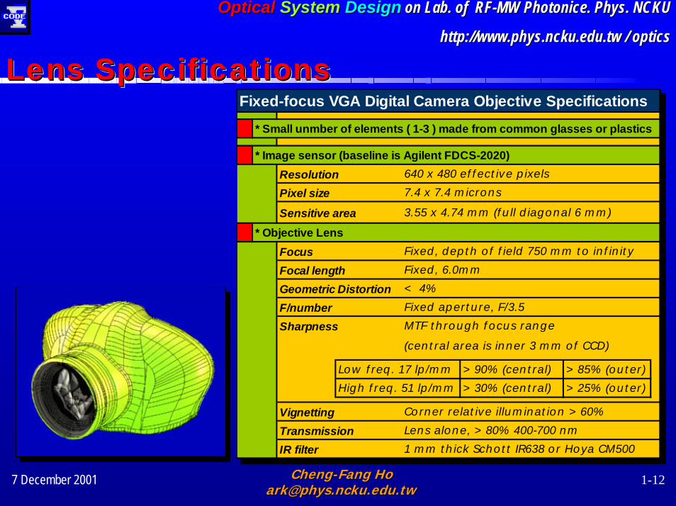
Fixed-focus VGA Digital Camera Objective Specifications* Small unmber of elements ( 1-3 ) made from common glasses or plastics
* Image sensor (baseline is Agilent FDCS-2020)Resolution 640 x 480 effective pixels
Pixel size 7.4 x 7.4 microns
Sensitive area 3.55 x 4.74 mm (full diagonal 6 mm)
* Objective LensFocus Fixed, depth of field 750 mm to infinity
Focal length Fixed, 6.0mm
Geometric Distortion < 4%
F/number Fixed aperture, F/3.5
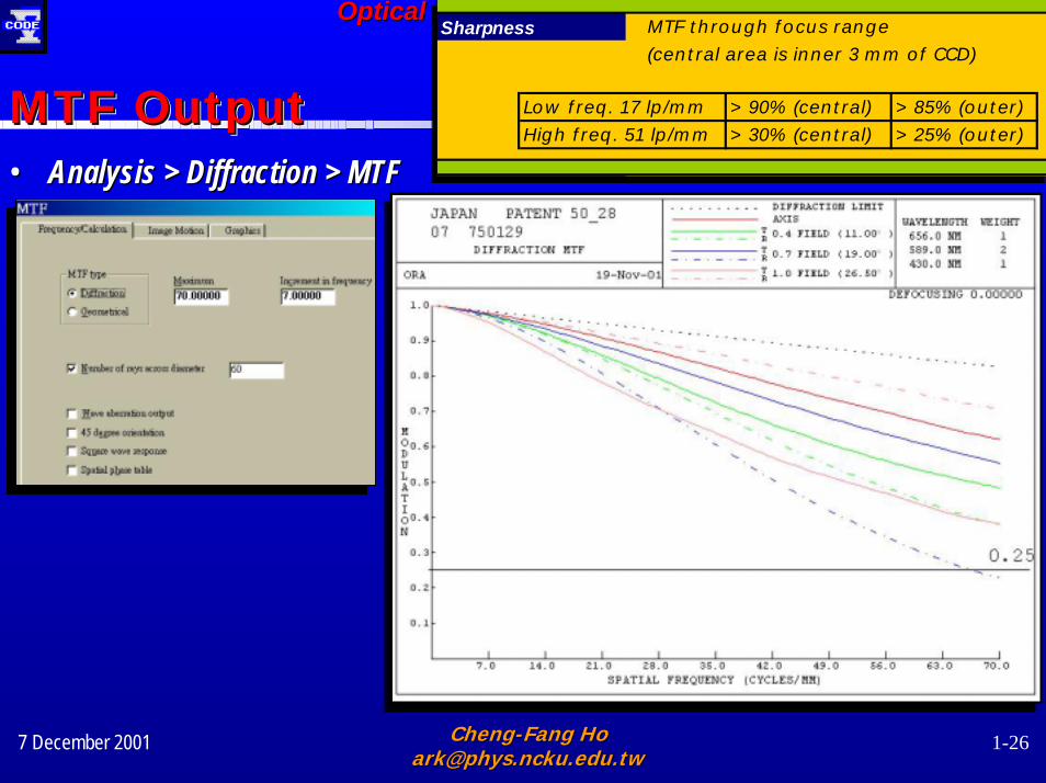
Sharpness MTF through focus range
(central area is inner 3 mm of CCD)
Low freq. 17 lp/mm >90% (central) >85% (outer)
High freq. 51 lp/mm >30% (central) >25% (outer)
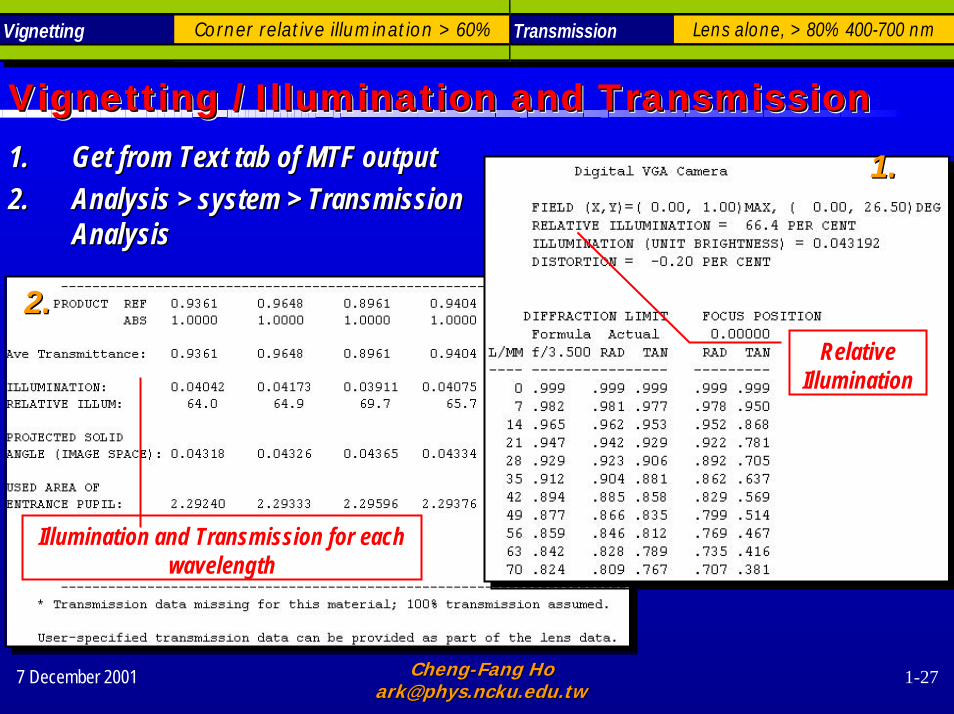
Vignetting Corner relative illumination >60%
Transmission Lens alone, >80% 400-700 nm
IR filter 1 mm thick Schott IR638 or Hoya CM500
Fixed-focus VGA Digital Camera Objective Specifications* Small unmber of elements ( 1-3 ) made from common glasses or plastics
* Image sensor (baseline is Agilent FDCS-2020)Resolution 640 x 480 effective pixels
Pixel size 7.4 x 7.4 microns
Sensitive area 3.55 x 4.74 mm (full diagonal 6 mm)
* Objective LensFocus Fixed, depth of field 750 mm to infinity
Focal length Fixed, 6.0mm
Geometric Distortion < 4%
F/number Fixed aperture, F/3.5
Sharpness MTF through focus range
(central area is inner 3 mm of CCD)
Low freq. 17 lp/mm >90% (central) >85% (outer)
High freq. 51 lp/mm >30% (central) >25% (outer)
Vignetting Corner relative illumination >60%
Transmission Lens alone, >80% 400-700 nm
IR filter 1 mm thick Schott IR638 or Hoya CM500
Lens SpecificationsLens SpecificationsLens Specifications
7 December 2001 ChengCheng--Fang Ho Fang Ho [email protected] [email protected]
1-13
OpticalOptical SystemSystem DesignDesign on Lab. of RFon Lab. of RF--MW MW PhotonicePhotonice. Phys. NCKU. Phys. NCKU
http://www.physhttp://www.phys.ncku.edu.tw.ncku.edu.tw / optics/ optics
Identification of a Starting Point Identification of a Starting Point Identification of a Starting Point
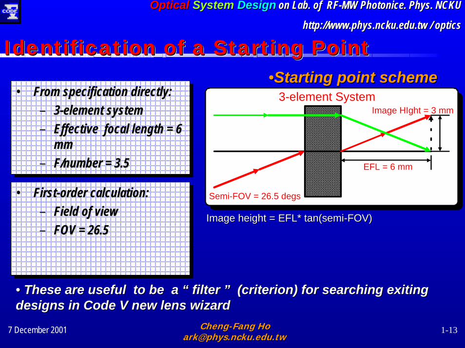
Image height = EFL* tan(semiImage height = EFL* tan(semi--FOV)FOV)
••Starting point schemeStarting point scheme
EFL = 6 mm
Semi-FOV = 26.5 degs
Image HIght = 3 mm3-element System• From specification directly:
– 3-element system– Effective focal length = 6
mm– F/number = 3.5
•• From specification directly:From specification directly:–– 33--element systemelement system–– Effective focal length = 6 Effective focal length = 6
mmmm–– F/number = 3.5F/number = 3.5
• First-order calculation:– Field of view– FOV = 26.5 °
•• FirstFirst--order calculation:order calculation:–– Field of viewField of view–– FOV = 26.5 FOV = 26.5 °°
•• These are useful to be a These are useful to be a ““ filter filter ”” (criterion) for searching exiting (criterion) for searching exiting designs in Code V new lens wizard designs in Code V new lens wizard
7 December 2001 ChengCheng--Fang Ho Fang Ho [email protected] [email protected]
1-14
OpticalOptical SystemSystem DesignDesign on Lab. of RFon Lab. of RF--MW MW PhotonicePhotonice. Phys. NCKU. Phys. NCKU
http://www.physhttp://www.phys.ncku.edu.tw.ncku.edu.tw / optics/ optics
Selecting a Suitable Starting Point
Selecting Selecting a Suitable Starting Point a Suitable Starting Point

7 December 2001 ChengCheng--Fang Ho Fang Ho [email protected] [email protected]
1-15
OpticalOptical SystemSystem DesignDesign on Lab. of RFon Lab. of RF--MW MW PhotonicePhotonice. Phys. NCKU. Phys. NCKU
http://www.physhttp://www.phys.ncku.edu.tw.ncku.edu.tw / optics/ optics
Selecting a suitable starting pointSelecting a suitable starting pointSelecting a suitable starting point•• The Code V New Lens WizardThe Code V New Lens Wizard
–– Searching existing designsSearching existing designs-- Patent DatabasePatent Database–– FilterFilter–– A suitable starting lensA suitable starting lens
3. 3. Lens name : Lens name : or022488or022488
1.1.
2.2.
7 December 2001 ChengCheng--Fang Ho Fang Ho [email protected] [email protected]
1-16
OpticalOptical SystemSystem DesignDesign on Lab. of RFon Lab. of RF--MW MW PhotonicePhotonice. Phys. NCKU. Phys. NCKU
http://www.physhttp://www.phys.ncku.edu.tw.ncku.edu.tw / optics/ optics
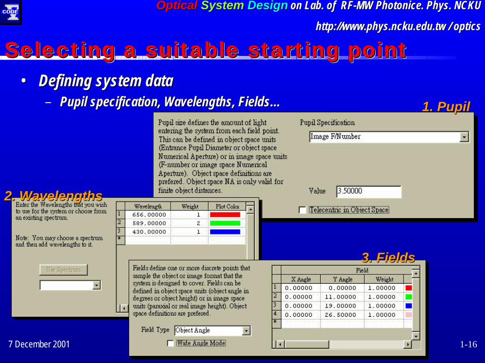
Selecting a suitable starting pointSelecting a suitable starting pointSelecting a suitable starting point•• Defining system dataDefining system data
–– Pupil specification, Wavelengths, FieldsPupil specification, Wavelengths, Fields…… 1. 1. PupilPupil
2. 2. WavelengthsWavelengths
3. 3. FieldsFields
7 December 2001 ChengCheng--Fang Ho Fang Ho [email protected] [email protected]
1-17
OpticalOptical SystemSystem DesignDesign on Lab. of RFon Lab. of RF--MW MW PhotonicePhotonice. Phys. NCKU. Phys. NCKU
http://www.physhttp://www.phys.ncku.edu.tw.ncku.edu.tw / optics/ optics
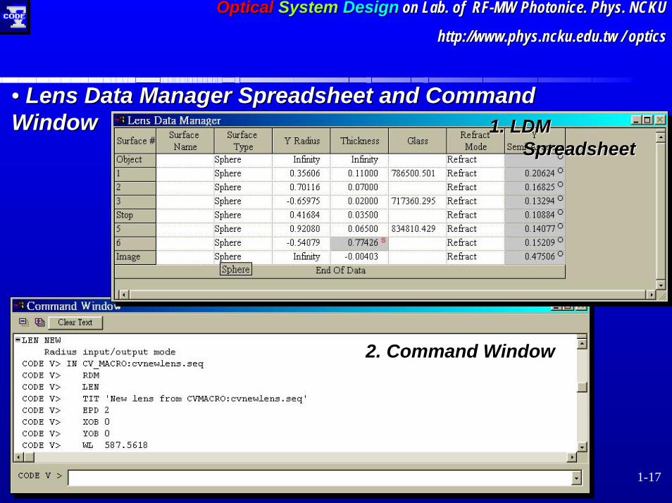
•• Lens Data Manager Spreadsheet and CommandLens Data Manager Spreadsheet and CommandWindowWindow 1. 1. LDM LDM
SpreadsheetSpreadsheet
2. 2. Command WindowCommand Window
7 December 2001 ChengCheng--Fang Ho Fang Ho [email protected] [email protected]
1-18
OpticalOptical SystemSystem DesignDesign on Lab. of RFon Lab. of RF--MW MW PhotonicePhotonice. Phys. NCKU. Phys. NCKU
http://www.physhttp://www.phys.ncku.edu.tw.ncku.edu.tw / optics/ optics
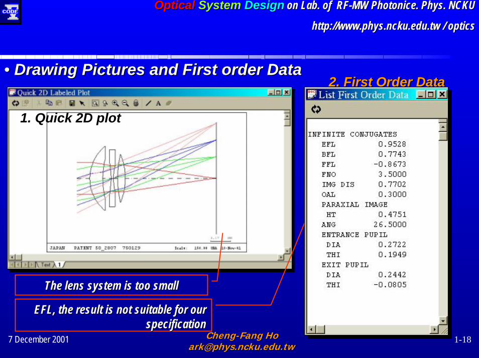
•• Drawing Pictures and First order DataDrawing Pictures and First order Data
1. 1. Quick 2D plotQuick 2D plot
2. 2. First Order DataFirst Order Data
The lens system is too smallThe lens system is too small
EFL, the result is not suitable for our EFL, the result is not suitable for our specification specification
7 December 2001 ChengCheng--Fang Ho Fang Ho [email protected] [email protected]
1-19
OpticalOptical SystemSystem DesignDesign on Lab. of RFon Lab. of RF--MW MW PhotonicePhotonice. Phys. NCKU. Phys. NCKU
http://www.physhttp://www.phys.ncku.edu.tw.ncku.edu.tw / optics/ optics
JAPAN PATENT 50_2807 750129 Scale: 24.00 ORA 18-Nov-01
1.04 MM
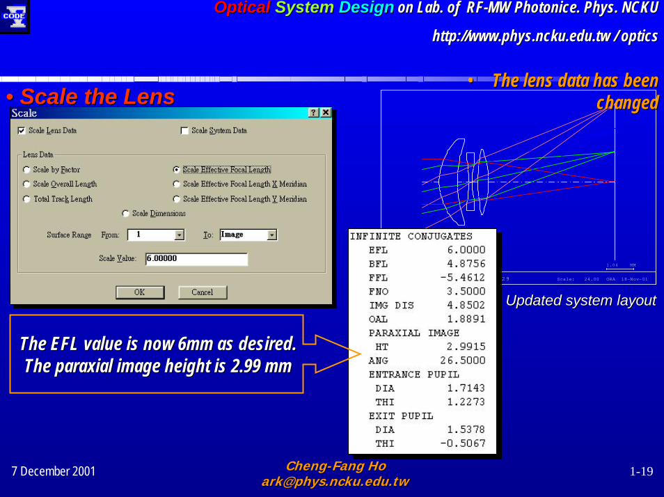
•• The lens data has been The lens data has been changedchanged
Updated system layoutUpdated system layout
•• Scale the Lens Scale the Lens
The EFL value is now 6mm as desired.The EFL value is now 6mm as desired.The paraxial image height is 2.99 mmThe paraxial image height is 2.99 mm
7 December 2001 ChengCheng--Fang Ho Fang Ho [email protected] [email protected]
1-20
OpticalOptical SystemSystem DesignDesign on Lab. of RFon Lab. of RF--MW MW PhotonicePhotonice. Phys. NCKU. Phys. NCKU
http://www.physhttp://www.phys.ncku.edu.tw.ncku.edu.tw / optics/ optics
Analyze the Starting Point
Analyze Analyze the Starting Point the Starting Point
7 December 2001 ChengCheng--Fang Ho Fang Ho [email protected] [email protected]
1-21
OpticalOptical SystemSystem DesignDesign on Lab. of RFon Lab. of RF--MW MW PhotonicePhotonice. Phys. NCKU. Phys. NCKU
http://www.physhttp://www.phys.ncku.edu.tw.ncku.edu.tw / optics/ optics
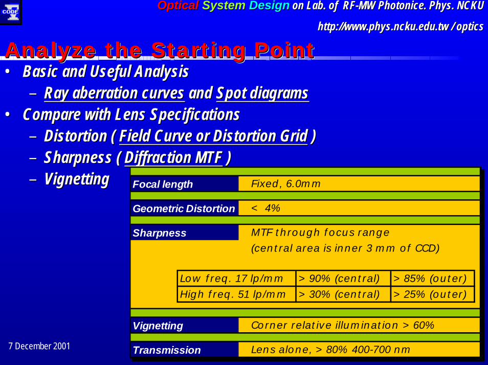
Analyze the Starting Point Analyze the Starting Point Analyze the Starting Point •• Basic and Useful AnalysisBasic and Useful Analysis
–– Ray aberration curvesRay aberration curves and and Spot diagramsSpot diagrams•• Compare with Lens SpecificationsCompare with Lens Specifications
–– Distortion ( Distortion ( Field Curve or Distortion GridField Curve or Distortion Grid ))–– Sharpness ( Sharpness ( Diffraction MTFDiffraction MTF ))–– VignettingVignetting Focal length Fixed, 6.0mm
Geometric Distortion < 4%
Sharpness MTF through focus range
(central area is inner 3 mm of CCD)
Low freq. 17 lp/mm >90% (central) >85% (outer)
High freq. 51 lp/mm >30% (central) >25% (outer)
Vignetting Corner relative illumination >60%
Transmission Lens alone, >80% 400-700 nm
Focal length Fixed, 6.0mm
Geometric Distortion < 4%
Sharpness MTF through focus range
(central area is inner 3 mm of CCD)
Low freq. 17 lp/mm >90% (central) >85% (outer)
High freq. 51 lp/mm >30% (central) >25% (outer)
Vignetting Corner relative illumination >60%
Transmission Lens alone, >80% 400-700 nm

7 December 2001 ChengCheng--Fang Ho Fang Ho [email protected] [email protected]
1-22
OpticalOptical SystemSystem DesignDesign on Lab. of RFon Lab. of RF--MW MW PhotonicePhotonice. Phys. NCKU. Phys. NCKU
http://www.physhttp://www.phys.ncku.edu.tw.ncku.edu.tw / optics/ optics
•• Analysis > Diagnostics > Ray Analysis > Diagnostics > Ray Aberration CurveAberration Curve
•• Ray Aberration CurvesRay Aberration CurvesRay Aberration and Spot DiagramRay Aberration and Spot DiagramRay Aberration and Spot Diagram
EnlargeEnlarge
Aberration scale Aberration scale PurplePurple

7 December 2001 ChengCheng--Fang Ho Fang Ho [email protected] [email protected]
1-23
OpticalOptical SystemSystem DesignDesign on Lab. of RFon Lab. of RF--MW MW PhotonicePhotonice. Phys. NCKU. Phys. NCKU
http://www.physhttp://www.phys.ncku.edu.tw.ncku.edu.tw / optics/ optics
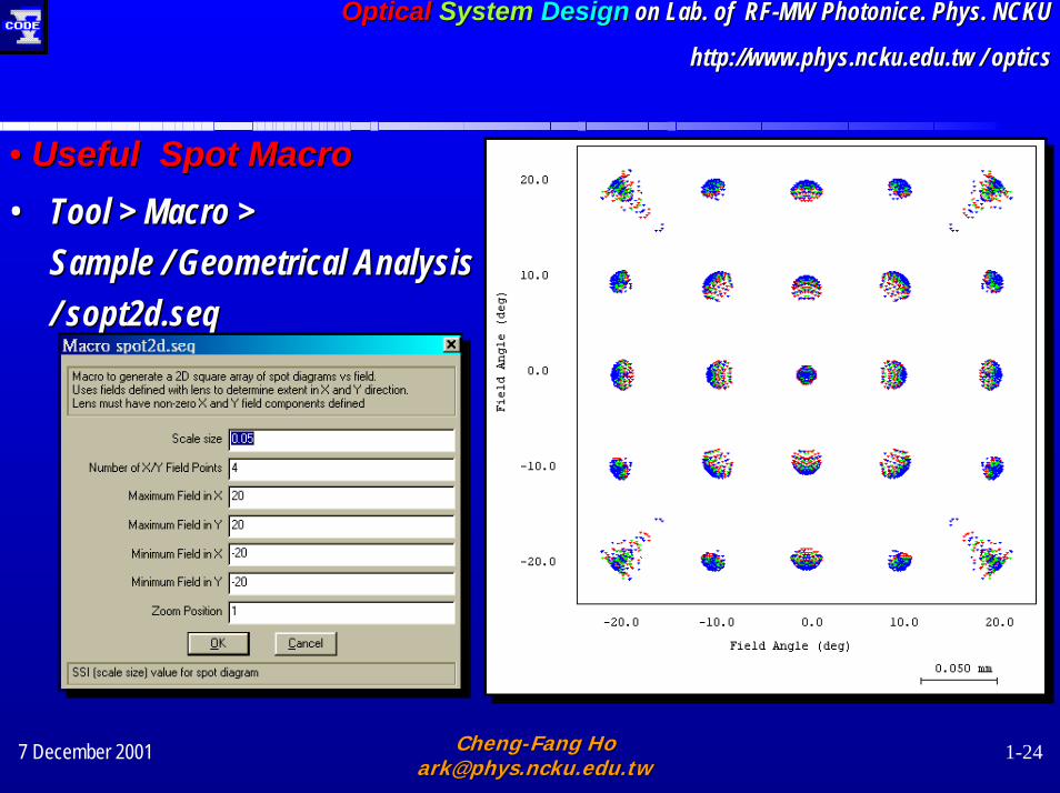
•• Spot DiagramSpot Diagram•• Analysis > Geometrical > Spot DiagramAnalysis > Geometrical > Spot Diagram
–– Scale by Scale by Pixel Size 7.4 umPixel Size 7.4 um
Scale barScale barField angle Field angle
7 December 2001 ChengCheng--Fang Ho Fang Ho [email protected] [email protected]
1-24
OpticalOptical SystemSystem DesignDesign on Lab. of RFon Lab. of RF--MW MW PhotonicePhotonice. Phys. NCKU. Phys. NCKU
http://www.physhttp://www.phys.ncku.edu.tw.ncku.edu.tw / optics/ optics
•• Tool > Macro > Tool > Macro > Sample / Geometrical AnalysisSample / Geometrical Analysis/ sopt2d/ sopt2d.seq.seq
•• Useful Spot Macro Useful Spot Macro

7 December 2001 ChengCheng--Fang Ho Fang Ho [email protected] [email protected]
1-25
OpticalOptical SystemSystem DesignDesign on Lab. of RFon Lab. of RF--MW MW PhotonicePhotonice. Phys. NCKU. Phys. NCKU
http://www.physhttp://www.phys.ncku.edu.tw.ncku.edu.tw / optics/ opticsGeometric Distortion < 4%Geometric Distortion < 4%
•• Analysis > Diagnostics > Field CurveAnalysis > Diagnostics > Field Curve•• Analysis > Diagnostics > Distortion Analysis > Diagnostics > Distortion
Grid Grid
1. 1. Field CurveField Curve
2. 2. Distortion GridDistortion Grid
Distortion Distortion Distortion
7 December 2001 ChengCheng--Fang Ho Fang Ho [email protected] [email protected]
1-26
OpticalOptical SystemSystem DesignDesign on Lab. of RFon Lab. of RF--MW MW PhotonicePhotonice. Phys. NCKU. Phys. NCKU
http://www.physhttp://www.phys.ncku.edu.tw.ncku.edu.tw / optics/ opticsSharpness MTF through focus range
(central area is inner 3 mm of CCD)
Low freq. 17 lp/mm >90% (central) >85% (outer)
High freq. 51 lp/mm >30% (central) >25% (outer)
Sharpness MTF through focus range
(central area is inner 3 mm of CCD)
Low freq. 17 lp/mm >90% (central) >85% (outer)
High freq. 51 lp/mm >30% (central) >25% (outer)
•• Analysis > Diffraction > MTFAnalysis > Diffraction > MTF
MTF OutputMTF OutputMTF Output
7 December 2001 ChengCheng--Fang Ho Fang Ho [email protected] [email protected]
1-27
OpticalOptical SystemSystem DesignDesign on Lab. of RFon Lab. of RF--MW MW PhotonicePhotonice. Phys. NCKU. Phys. NCKU
http://www.physhttp://www.phys.ncku.edu.tw.ncku.edu.tw / optics/ opticsVignetting Corner relative illumination >60%Vignetting Corner relative illumination >60%
1.1. Get from Text tab of MTF outputGet from Text tab of MTF output2.2. Analysis > system > Transmission Analysis > system > Transmission
AnalysisAnalysis
Vignetting / Illumination and TransmissionVignetting Vignetting / Illumination and Transmission/ Illumination and Transmission
Transmission Lens alone, >80% 400-700 nmTransmission Lens alone, >80% 400-700 nm
1.1.
2.2.
Illumination and Transmission for each wavelength
Relative Illumination
7 December 2001 ChengCheng--Fang Ho Fang Ho [email protected] [email protected]
1-28
OpticalOptical SystemSystem DesignDesign on Lab. of RFon Lab. of RF--MW MW PhotonicePhotonice. Phys. NCKU. Phys. NCKU
http://www.physhttp://www.phys.ncku.edu.tw.ncku.edu.tw / optics/ optics
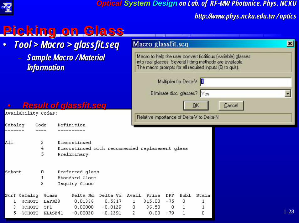
•• Tool > Macro > Tool > Macro > glassfit.seqglassfit.seq–– Sample Macro / Material Sample Macro / Material
InformationInformation
Picking on Glass Picking on Glass Picking on Glass
•• Result of Result of glassfit.seqglassfit.seq
7 December 2001 ChengCheng--Fang Ho Fang Ho [email protected] [email protected]
1-29
OpticalOptical SystemSystem DesignDesign on Lab. of RFon Lab. of RF--MW MW PhotonicePhotonice. Phys. NCKU. Phys. NCKU
http://www.physhttp://www.phys.ncku.edu.tw.ncku.edu.tw / optics/ optics
Optimization:Making Things Better
Optimization:Optimization:Making Things Better Making Things Better

7 December 2001 ChengCheng--Fang Ho Fang Ho [email protected] [email protected]
1-30
OpticalOptical SystemSystem DesignDesign on Lab. of RFon Lab. of RF--MW MW PhotonicePhotonice. Phys. NCKU. Phys. NCKU
http://www.physhttp://www.phys.ncku.edu.tw.ncku.edu.tw / optics/ optics
Automatic Design Process Automatic Design Process Automatic Design Process
Process
StartingdesignSetup
Choice ofvariables
Choice of constraints,error function controls,
other controls
Auto input
Constructerror
function
Evaluateerror
function
Develop finitedifferences foreach constraintand aberration
Evaluatedesign
STOP (good enough)
Not good enought re-enterprocess at A, B, C, or D
Print each cycle foruser feedback
* EXIT
A
B
C
DCODEV/AUTO tasks
Yes
No
Designer Tasks
Designer Tasks :
7 December 2001 ChengCheng--Fang Ho Fang Ho [email protected] [email protected]
1-31
OpticalOptical SystemSystem DesignDesign on Lab. of RFon Lab. of RF--MW MW PhotonicePhotonice. Phys. NCKU. Phys. NCKU
http://www.physhttp://www.phys.ncku.edu.tw.ncku.edu.tw / optics/ optics
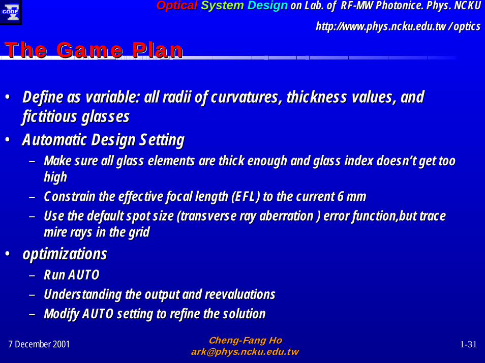
The Game PlanThe Game PlanThe Game Plan
•• Define as variable: all radii of curvatures, thickness values, aDefine as variable: all radii of curvatures, thickness values, and nd fictitious glassesfictitious glasses
•• Automatic Design SettingAutomatic Design Setting–– Make sure all glass elements are thick enough and glass index Make sure all glass elements are thick enough and glass index doesndoesn’’t get too t get too
highhigh–– Constrain the effective focal length (EFL) to the current 6 mmConstrain the effective focal length (EFL) to the current 6 mm–– Use the default spot size (transverse ray aberration ) error funUse the default spot size (transverse ray aberration ) error function,but trace ction,but trace
mire rays in the gridmire rays in the grid•• optimizations optimizations
–– Run AUTORun AUTO–– Understanding the output and reevaluations Understanding the output and reevaluations –– Modify AUTO setting to refine the solutionModify AUTO setting to refine the solution
7 December 2001 ChengCheng--Fang Ho Fang Ho [email protected] [email protected]
1-32
OpticalOptical SystemSystem DesignDesign on Lab. of RFon Lab. of RF--MW MW PhotonicePhotonice. Phys. NCKU. Phys. NCKU
http://www.physhttp://www.phys.ncku.edu.tw.ncku.edu.tw / optics/ optics
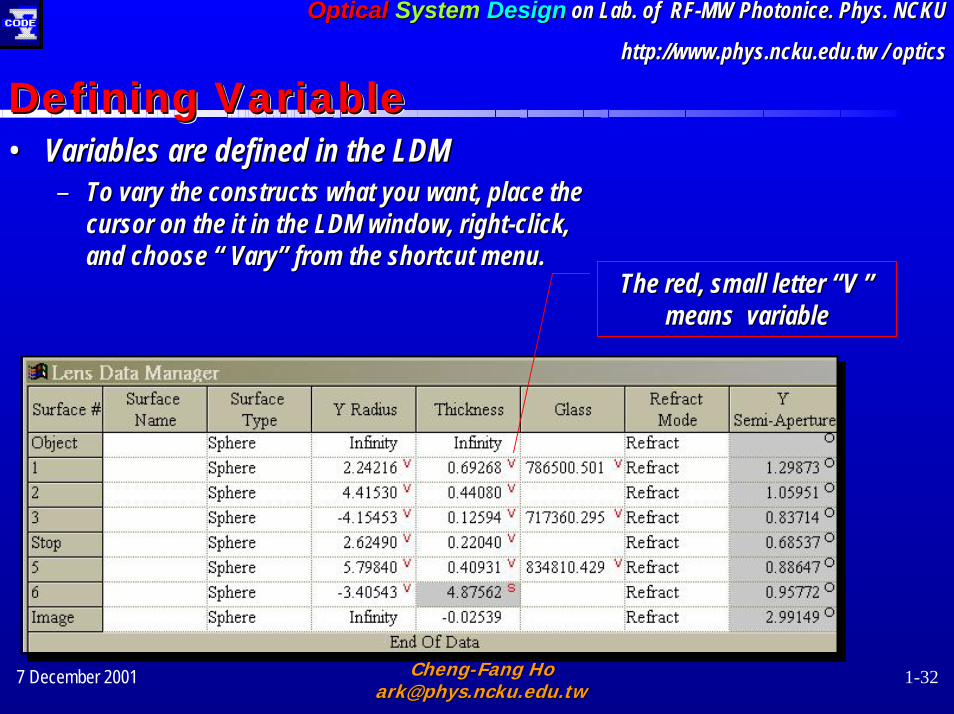
•• Variables are defined in the LDMVariables are defined in the LDM–– To vary the constructs what you want, place the To vary the constructs what you want, place the
cursor on the it in the LDM window, rightcursor on the it in the LDM window, right--click, click, and choose and choose ““ VaryVary”” from the shortcut menu.
Defining Variable Defining Variable Defining Variable
from the shortcut menu. The red, small letter The red, small letter ““V V ””
means variable means variable

7 December 2001 ChengCheng--Fang Ho Fang Ho [email protected] [email protected]
1-33
OpticalOptical SystemSystem DesignDesign on Lab. of RFon Lab. of RF--MW MW PhotonicePhotonice. Phys. NCKU. Phys. NCKU
http://www.physhttp://www.phys.ncku.edu.tw.ncku.edu.tw / optics/ optics
Automatic Design SettingAutomatic Design SettingAutomatic Design Setting•• The first boundary condition category is The first boundary condition category is General ConstraintGeneral Constraint
–– General Thickness ConstraintGeneral Thickness Constraint–– Glass Map ConstraintGlass Map Constraint
•• The second boundary condition category is The second boundary condition category is Specific ConstraintSpecific Constraint–– Edit Constraint : Optical Definition / First Order or Third OrdeEdit Constraint : Optical Definition / First Order or Third Order r
Aberration Aberration …………–– Defining Constraint Mode and Constraint TargetDefining Constraint Mode and Constraint Target
•• Error Function Definitions and ControlsError Function Definitions and Controls–– Error Function TypesError Function Types
•• Output ControlsOutput Controls

7 December 2001 ChengCheng--Fang Ho Fang Ho [email protected] [email protected]
1-34
OpticalOptical SystemSystem DesignDesign on Lab. of RFon Lab. of RF--MW MW PhotonicePhotonice. Phys. NCKU. Phys. NCKU
http://www.physhttp://www.phys.ncku.edu.tw.ncku.edu.tw / optics/ optics
General ConstraintGeneral ConstraintGeneral Constraint•• Min. center thicknessMin. center thickness
–– 0.9 mm0.9 mm•• Min. edge thicknessMin. edge thickness
–– 0.8 mm0.8 mm•• Defining new corner Defining new corner
point for the glass map point for the glass map

7 December 2001 ChengCheng--Fang Ho Fang Ho [email protected] [email protected]
1-35
OpticalOptical SystemSystem DesignDesign on Lab. of RFon Lab. of RF--MW MW PhotonicePhotonice. Phys. NCKU. Phys. NCKU
http://www.physhttp://www.phys.ncku.edu.tw.ncku.edu.tw / optics/ optics
•• ConstraintConstraint–– EFL EFL
Specific ConstraintSpecific ConstraintSpecific Constraint
Constraint Constraint categorycategory
Constraints Constraints
Constraints Constraints modemode
7 December 2001 ChengCheng--Fang Ho Fang Ho [email protected] [email protected]
1-36
OpticalOptical SystemSystem DesignDesign on Lab. of RFon Lab. of RF--MW MW PhotonicePhotonice. Phys. NCKU. Phys. NCKU
http://www.physhttp://www.phys.ncku.edu.tw.ncku.edu.tw / optics/ optics
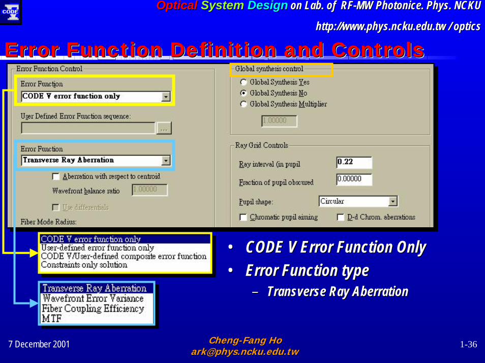
•• CODE V Error Function OnlyCODE V Error Function Only•• Error Function type Error Function type
–– Transverse Ray Aberration Transverse Ray Aberration
Error Function Definition and ControlsError Function Definition and ControlsError Function Definition and Controls
7 December 2001 ChengCheng--Fang Ho Fang Ho [email protected] [email protected]
1-37
OpticalOptical SystemSystem DesignDesign on Lab. of RFon Lab. of RF--MW MW PhotonicePhotonice. Phys. NCKU. Phys. NCKU
http://www.physhttp://www.phys.ncku.edu.tw.ncku.edu.tw / optics/ optics
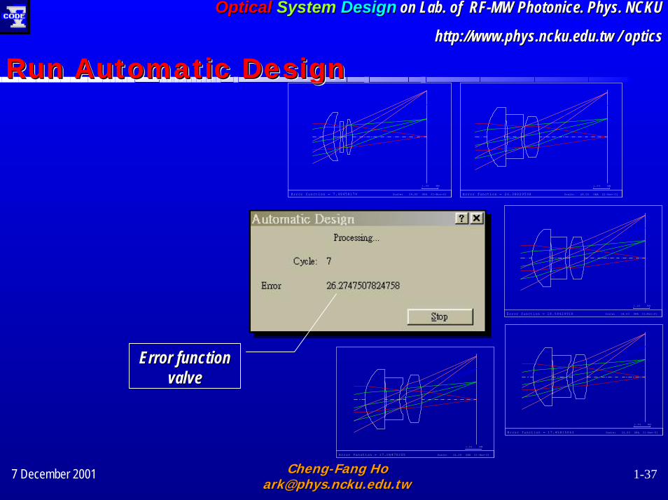
Run Automatic DesignRun Automatic DesignRun Automatic Design
Error function = 7.48458174 Scale: 24.00 ORA 21-Nov-01
1.04 MM
Error function = 26.38829598 Scale: 24.00 ORA 21-Nov-01
1.04 MM
Error function = 18.58429918 Scale: 24.00 ORA 21-Nov-01
1.04 MM
Error function = 17.45815063 Scale: 24.00 ORA 21-Nov-01
1.04 MM
Error function = 17.06470255 Scale: 24.00 ORA 21-Nov-01
1.04 MM
Error function Error function valvevalve
7 December 2001 ChengCheng--Fang Ho Fang Ho [email protected] [email protected]
1-38
OpticalOptical SystemSystem DesignDesign on Lab. of RFon Lab. of RF--MW MW PhotonicePhotonice. Phys. NCKU. Phys. NCKU
http://www.physhttp://www.phys.ncku.edu.tw.ncku.edu.tw / optics/ optics
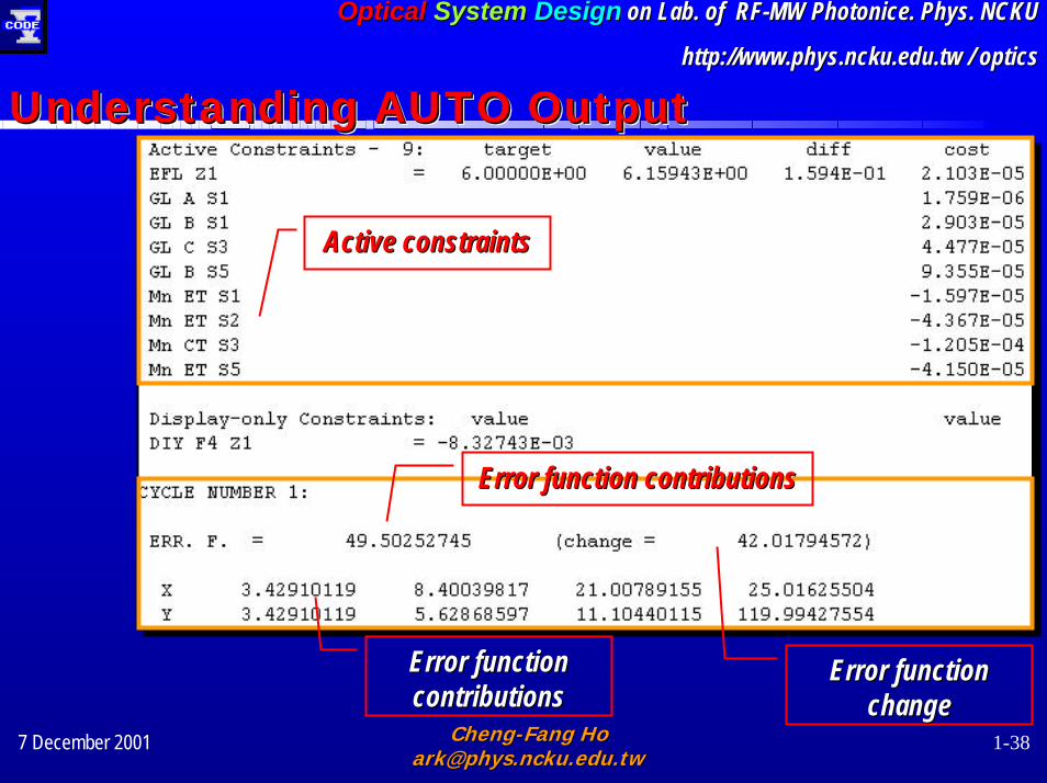
Understanding AUTO OutputUnderstanding AUTO OutputUnderstanding AUTO Output
Active constraintsActive constraints
Error function contributionsError function contributions
Error function Error function contributions
Error function Error function changecontributions change
7 December 2001 ChengCheng--Fang Ho Fang Ho [email protected] [email protected]
1-39
OpticalOptical SystemSystem DesignDesign on Lab. of RFon Lab. of RF--MW MW PhotonicePhotonice. Phys. NCKU. Phys. NCKU
http://www.physhttp://www.phys.ncku.edu.tw.ncku.edu.tw / optics/ optics
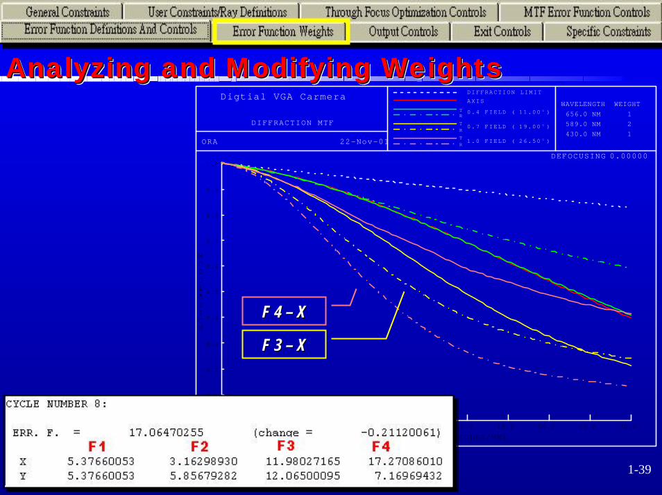
Analyzing and Modifying WeightsAnalyzing and Modifying WeightsAnalyzing and Modifying Weights
1.0
0.9
0.8
0.7
0.6
0.5
0.4
0.3
0.2
0.1
MODULATION
7.0 14.0 21.0 28.0 35.0 42.0 49.0 56.0 63.0 70.0
SPATIAL FREQUENCY (CYCLES/MM)
Digtial VGA Carmera
DIFFRACTION MTF
ORA 22-Nov-01
DIFFRACTION LIMIT
AXIS
T R
0.4 FIELD ( )11.00 O
T R
0.7 FIELD ( )19.00 O
T R
1.0 FIELD ( )26.50 O
WAVELENGTH WEIGHT
656.0 NM 1
589.0 NM 2
430.0 NM 1
DEFOCUSING 0.00000
F 3 F 3 –– X X
F 4 F 4 –– X X
7 December 2001 ChengCheng--Fang Ho Fang Ho [email protected] [email protected]
1-40
OpticalOptical SystemSystem DesignDesign on Lab. of RFon Lab. of RF--MW MW PhotonicePhotonice. Phys. NCKU. Phys. NCKU
http://www.physhttp://www.phys.ncku.edu.tw.ncku.edu.tw / optics/ optics
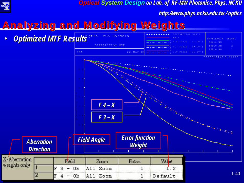
•• Optimized MTF ResultsOptimized MTF ResultsAnalyzing and Modifying WeightsAnalyzing and Modifying WeightsAnalyzing and Modifying Weights
1.0
0.9
0.8
0.7
0.6
0.5
0.4
0.3
0.2
0.1
MODULATION
7.0 14.0 21.0 28.0 35.0 42.0 49.0 56.0 63.0 70.0
SPATIAL FREQUENCY (CYCLES/MM)
Digtial VGA Carmera
DIFFRACTION MTF
ORA 22-Nov-01
DIFFRACTION LIMIT
AXIS
T R
0.4 FIELD ( )11.00 O
T R
0.7 FIELD ( )19.00 O
T R
1.0 FIELD ( )26.50 O
WAVELENGTH WEIGHT
656.0 NM 1
589.0 NM 2
430.0 NM 1
DEFOCUSING 0.00000
Error function Error function WeightWeight
F 3 F 3 –– X X
Field AngleField AngleAberration Aberration DirectionDirection
F 4 F 4 –– X X

7 December 2001 ChengCheng--Fang Ho Fang Ho [email protected] [email protected]
1-41
OpticalOptical SystemSystem DesignDesign on Lab. of RFon Lab. of RF--MW MW PhotonicePhotonice. Phys. NCKU. Phys. NCKU
http://www.physhttp://www.phys.ncku.edu.tw.ncku.edu.tw / optics/ optics
•• The results are accepted for infinite The results are accepted for infinite objection distanceobjection distance
Optimization and Re-evaluations (1) Optimization and ReOptimization and Re--evaluations (1) evaluations (1)
1.0
0.9
0.8
0.7
0.6
0.5
0.4
0.3
0.2
0.1
MODULATION
7.0 14.0 21.0 28.0 35.0 42.0 49.0 56.0 63.0 70.0
SPATIAL FREQUENCY (CYCLES/MM)
Digtial VGA Carmera
DIFFRACTION MTF
ORA 22-Nov-01
DIFFRACTION LIMIT
AXIS
T R
0.4 FIELD ( )11.00 O
T R
0.7 FIELD ( )19.00 O
T R
1.0 FIELD ( )26.50 O
WAVELENGTH WEIGHT
656.0 NM 1
589.0 NM 2
430.0 NM 1
DEFOCUSING 0.00000
0.25

7 December 2001 ChengCheng--Fang Ho Fang Ho [email protected] [email protected]
1-42
OpticalOptical SystemSystem DesignDesign on Lab. of RFon Lab. of RF--MW MW PhotonicePhotonice. Phys. NCKU. Phys. NCKU
http://www.physhttp://www.phys.ncku.edu.tw.ncku.edu.tw / optics/ optics
•• Optimization for objection distance =750 mmOptimization for objection distance =750 mm–– Consider the defocus effect (Through Consider the defocus effect (Through
focus) focus) –– The error functions are weighting by The error functions are weighting by
different focus different focus
••MTF (object MTF (object distance 750 mm)distance 750 mm)
Optimization and Re-evaluations (2) Optimization and ReOptimization and Re--evaluations (2) evaluations (2) Defocus Defocus definingdefining
Focus Focus assigningassigning
7 December 2001 ChengCheng--Fang Ho Fang Ho [email protected] [email protected]
1-43
OpticalOptical SystemSystem DesignDesign on Lab. of RFon Lab. of RF--MW MW PhotonicePhotonice. Phys. NCKU. Phys. NCKU
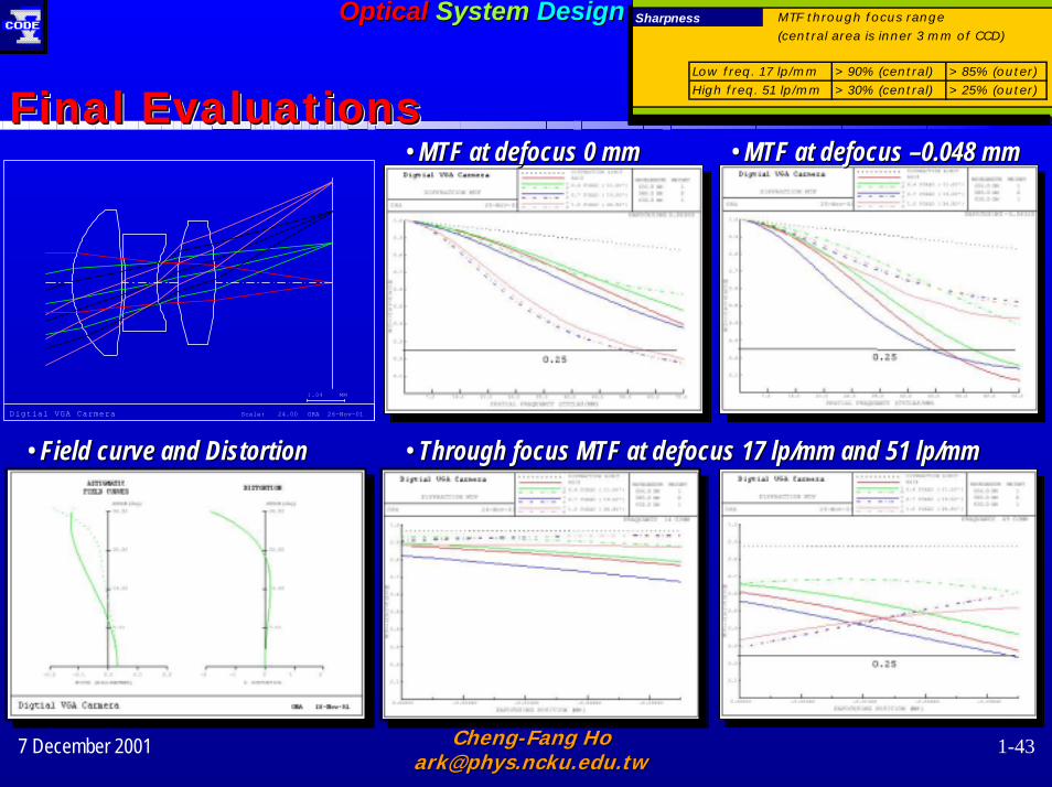
http://www.physhttp://www.phys.ncku.edu.tw.ncku.edu.tw / optics/ opticsSharpness MTF through focus range
(central area is inner 3 mm of CCD)
Low freq. 17 lp/mm >90% (central) >85% (outer)
High freq. 51 lp/mm >30% (central) >25% (outer)
Sharpness MTF through focus range
(central area is inner 3 mm of CCD)
Low freq. 17 lp/mm >90% (central) >85% (outer)
High freq. 51 lp/mm >30% (central) >25% (outer)
Final Evaluations Final Evaluations Final Evaluations •• MTF at defocus MTF at defocus ––0.048 mm0.048 mm•• MTF at defocus 0 mmMTF at defocus 0 mm
Digtial VGA Carmera Scale: 24.00 ORA 26-Nov-01
1.04 MM
•• Through focus MTF at defocus 17 Through focus MTF at defocus 17 lplp/mm and 51 /mm and 51 lplp/mm/mm•• Field curve and Distortion Field curve and Distortion
7 December 2001 ChengCheng--Fang Ho Fang Ho [email protected] [email protected]
1-44
OpticalOptical SystemSystem DesignDesign on Lab. of RFon Lab. of RF--MW MW PhotonicePhotonice. Phys. NCKU. Phys. NCKU
http://www.physhttp://www.phys.ncku.edu.tw.ncku.edu.tw / optics/ optics
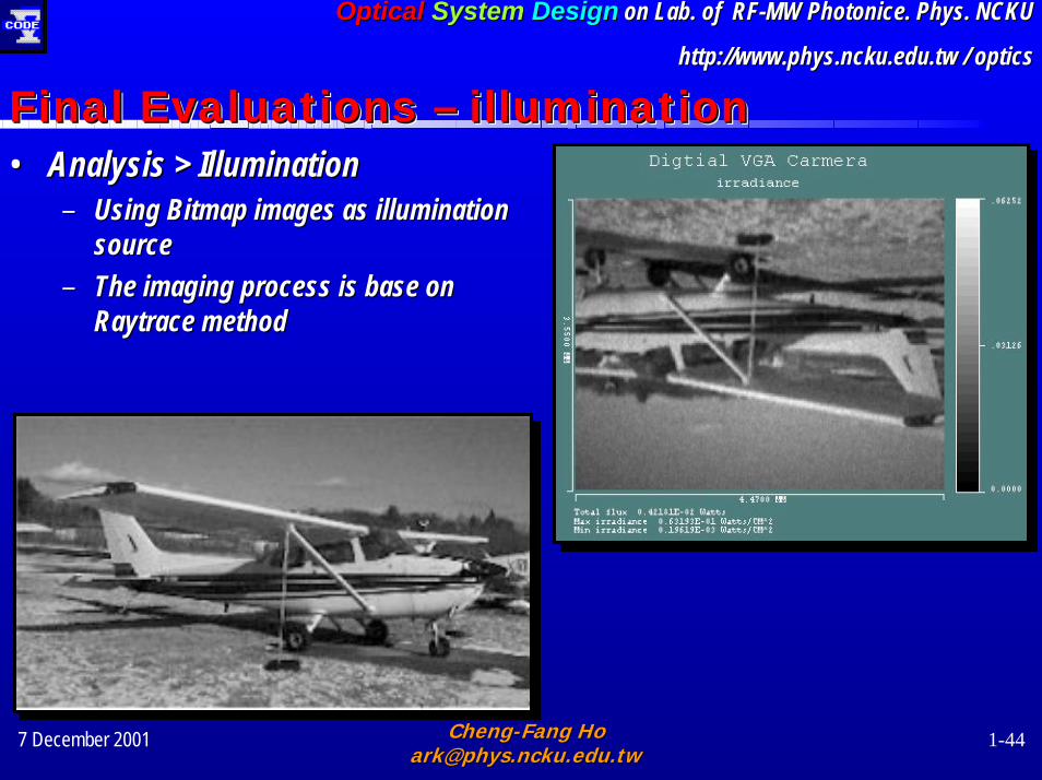
Final Evaluations – illumination Final Evaluations Final Evaluations –– illumination illumination •• Analysis > Illumination Analysis > Illumination
–– Using Bitmap images as illumination Using Bitmap images as illumination sourcesource
–– The imaging process is base on The imaging process is base on Raytrace Raytrace method method