codeline 80s series & 80h series 8ic ide et ry emb...
TRANSCRIPT

advanced filtration user guide
user guide
8iNCH side eNTrY MeMBrANe HOusiNg WiTH OCTA TeCHNOLOgY FOr rO APPLiCATiONSCODELINE® - 80S SERIES & 80H SERIES
ARTICLE CODE: 94182
1
Content Page No.Danger- high pressure device 2Operation/ maintenance guide 2Important safety precautions 2Preface 3Installation notes 4Pre-pressurization checklist 5Component identification 80S05 - Coded 6Component identification:80S15, 80S30, 80S45, 80S60, 80S100, 80S120 - Coded
7
Component Identification: 80S15, 80S30, 80S45, 80S60 – Non-Coded
8
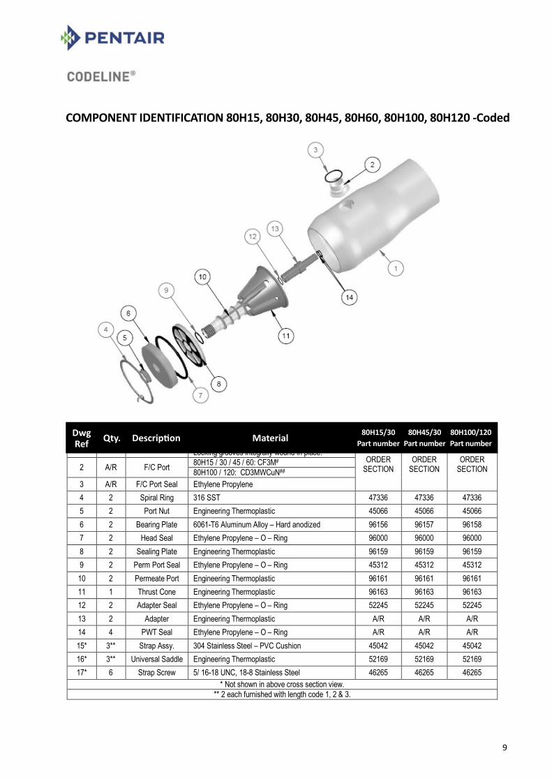
Component identification : 80H15, 80H30, 80H45, 80H60, 80H100, 80H120 - Coded
9
Component identification : Opening the vessel 10Replacing elements 12Closing the vessel 14Head – dis-assembling & assembling 17Preventive maintenance 23Trouble shooting 24Installation Guide: Introduction 27Handling, receiving and storage 28Mounting shell & piping connection 29Application guide 31Elasticity and mounting requirements 32Corrosion 33Safety 33Piping recommendations 35CodeLine® - Multi-portTM 38Pentair Water – Limited Warranty 42Disclaimer 45
2
DANGER – HIGH PRESSURE DEVICE Incorrect Installation, Operation & maintenance of these vessels may cause loss of life, severe bodily harm, and / or property damage. Read and understand all guidelines given in this bulletin before attempting to open, service or operate these vessels. Failure to follow these guidelines and observe every precaution may result in malfunction and could result in catastrophic failure. Misuse, incorrect assembly or use of damaged or corroded components can result in explosive release of the end closure. We recommend that only a qualified technician experienced in servicing highpressure hydraulic systems, open, close and service these vessels.
Operation and maintenance guideThis section is a guide to proper operation and maintenance of CodeLine® OCTA Series pressure vessels. Good industrial practice must be used in applying this information to assure safe vessel use. These guidelines are not intended to relieve the user from full responsibility for correct operation and maintenance of the vessels. For technical specifications and dimensions, refer to the Engineering Drawings of each specific model. The information in all sections must be carefully followed for the installation, operation & maintenance of the vessel to provide safe, long service life for which it is designed.
Important Safety PrecautionsDo’s• Read, understand and follow every part of this
section. Failure to take every precaution may void warranty and could result in explosive head failure.
• Install in an area where water leakage resulting from a vessel or piping malfunction would not damage sensitive equipment, such as electronic components.
• Install protective covering over equipment located below pressure vessels when performing maintenance.
• Verify that head locking components are properly placed and secured.
• Inspect end closures regularly, replace deteriorated components and correct causes of corrosion.
• Follow membrane element manufacturer’s recommendations for loading elements into vessel (see Replacing Elements on page no. 12).
Don’ts• Operate vessel at pressures in excess of their
specific rating. • Service any component until you verify that
pressure if fully relieved from the vessel. • Use corroded components. Use of such
components may result in catastrophic failure. • Pressurize vessel until after visually inspecting to
ensure that both locking segments are correctly installed and seated in their grooves.
• Tolerate leaks or allow end closures to be wetted in any way.
• Allow petroleum or silicone based products to come in contact with membrane elements during installation or maintenance.
• Use petroleum products on Noryl components. • Pressurize vessel without element in place,
unless permeate ports are plugged properly. • Over-tighten fittings in ports. • Stand or climb on the pressure vessels, or the
feed / concentrate or permeate ports. • Allow force in excess of 15 lbs to be applied
laterally to feed/concentrate or permeate ports. • Use the vessel at negative pressure
3
Preface
The CodeLine® Series Family of Vessels
The CodeLine® OCTA is a standardized series of fiberglass pressure vessels designed for continuous, long-term use as housings for reverse osmosis, nano-filtration, ultra-filtration and micro-filtration membranes. Any make of an eight-inch diameter spiral-wound membrane element can be easily accommodated in these vessels.
The CodeLine® OCTA Series is designed for different pressure ratings. They are unified in design and have maximum number of parts in common. Each model has the appropriate strength and materials of construction to provide years of continuous use in typical service when properly maintained. Each model is available in lengths, to house from one to eight, 40-inch long membrane elements. One to five membrane elements of 60-inch length, can also be accommodated.
The CodeLine® OCTA Series is designed and built in accordance with the engineering standards of the Boiler and Pressure Vessel Code of the American Society of Mechanical Engineers (ASME Code). A vessel marked with ASME Code stamp is accepted worldwide as being built to the highest standard of safety.
Each model in the CodeLine® OCTA Series has passed rigorous ASME Code qualification tests which require that the vessels do not burst at less than six times their design pressure. Safe use is further assured in that vessels will not fail catastrophically; overpressure is relieved by weeping through the fiberglass shell. Also, every production vessel is hydro-tested to verify structural integrity.
While undertaking regular maintenance / repair / replacement of a pressure vessel it may be necessary to remove the pressure vessel from a bank. Also ensure sufficient spares are available for replacement. Care must be taken in installation / removal of the vessel to avoid damage to the shell. Damage to the shell can result in catastrophic failure and possible injury to personnel. Any corrections or recommendation for improvement for this manual should be addressed to:
CodeLine® Division Pentair Water India Pvt. Ltd. L/52-55, Verna Industrial Area Verna, Goa – 403 722. INDIA Tel: 91-832-2883300 Fax: 91-832-2883312

4
Installation notes
Even though your vessel may be installed by others, there are few installation checks that you should make before system start-up. Vessels must be installed correctly to ensure safe use and long service life.• Check that vessels are mounted on horizontal support frame using compatible black urethane saddles with
hold-down straps that are snug & not tight.• Check that each vessel is free to expand under pressure, shell is not rigidly clamped in place, and piping to
vessel is not connected using rigid connections.• Check that vessel does not support any other component; that piping manifolds are separately mounted,
and that interconnection piping is self supported and connected to the pressure vessel with IPS grooved couplings.
If you have any question about the installation of vessel in your unit, contact your supplier. For installation guidelines, refer to page no. 27-29.
WARNING: Failure to allow expansion in diameter or length will result in vessel damage.
6
INSTALLATION NOTES
Even though your vessel may be installed by others, there are few installation checks that you
should make before system start-up. Vessels must be installed correctly to ensure safe use and
long service life.
Check that vessels are mounted on horizontal support frame using compatible
black urethane saddles with hold-down straps that are snug & not tight.
Check that each vessel is free to expand under pressure, shell is not rigidly
clamped in place, and piping to vessel is not connected using rigid connections.
Check that vessel does not support any other component; that piping manifolds
are separately mounted, and that interconnection piping is self supported and
connected to the pressure vessel with IPS grooved couplings.
FAILURE TO ALLOW EXPANSION IN DIAMETER OR LENGTH WILL RESULT IN VESSEL DAMAGE.
WARNING
If you have any question about the installation of vessel in your unit, contact your supplier. For installation guidelines, refer to page no. 28-30.
Models 80S05 80S15 80H15
80S30 80H30
80S45 80H45
80S60 80H60
80S100 80H100
80S120 80H120
Max. Operating Pressure (PSI)
75 150 300 450 600 1000 1200
Operating Temp. Range
(degree F) 20 – 120 20 – 190 20 – 190 20 – 190 20 – 190 20 – 150 20 – 150
Factory Test Pressure (PSI) ASME (1.1X)
82.5 165 330 495 660 1100 1320
Factory Test Pressure (PSI) CE/PED (1.5X)
112.5 225 450 675 900 1500 1800
Prototype Min. Qualification
Pressure (PSI) 450 900 1800 2700 3600 6000 7200
Engineering Drawing No. 99180
80S: 99159 80H: 99165
80S: 99160 80H: 99166
80S: 99161 80H: 99167
80S: 99162 80H: 99168
80S: 99163 80H: 99169
80S: 99164 80H: 99170

5
Pre-pressurization checklist
DANGER – HIGH PRESSURE DEVICEIncorrect Installation, Operation & maintenance of these vessels may cause loss of life, severe bodily harm, and / or property damage. Read and understand all guidelines given in this bulletin before attempting to open, service or operate these vessels. Failure to follow these guidelines and observe every precaution may result in malfunction and could result in catastrophic failure. Misuse, incorrect assembly or use of damaged or corroded components can result in explosive release of the end closure. We recommend that only a qualified technician experienced in servicing highpressure hydraulic systems, open, close and service these vessels.
Membrane elementsn Installed per manufacturer’s recommendation. n Feed flow direction correctly noted and elements correctly oriented.
Head assembly interlock n Retaining Ring groove at each end of the shell is clean, free of corrosion and / or delamination with
outboard face of groove true and is in sound condition. n All components in as-new condition, clean and free of damage or corrosion. n Retaining Ring is fully seated in the vessel Retaining Ring groove.
Element interfacen Adapters installed at both ends and element column. n Thrust cone installed downstream (concentrate or brine end) of the element column.
Head n All components in as-new condition clean and free of damage or corrosion. n All components are properly assembled with new, freshly lubricated seals. n Permeate port locking ring/nut installed. n Head marked with proper pressure rating for system.
Piping connections n Properly aligned (strain free) and secured. n Leak free.
4
Membrane elements Installed per manufacturer’s recommendation. Feed flow direction correctly noted and elements correctly oriented. Column of elements centered inside shell
Element interface Adapters installed at both ends of element column. Thrust ring installed downstream from element column.
Head All components in as-new condition clean and free of damage or corrosion. All components are properly assembled with new, freshly lubricated seals. Port retainer for feed/concentrate port in correct position. Port nut snug - 80E45 / 60 (Note: left-hand thread) Permeate port snap ring installed – 80E30
Head assembly Interlock Locking groove at each end of the shell is clean, free of corrosion and / or delamination with outboard
face of groove true and is in sound condition. All components in as-new condition, clean and free of damage or corrosion. Retaining ring is fully seated in the retaining ring groove. Piping connections Properly secured. Leak free.
Component Identification 80E30
Assembly by: _______________ Date Assembly: _______________ Checked by: _______________ Date of Inspection: _______________ The following vessels listed by serial number below were serviced under this checklist: ____________ _____________ _____________ __________ ___ _____________

6
7
COMPONENT IDENTIFICATION 80S05 - Coded COMPONENT IDENTIFICATION
80S05 - Coded
DwgRef Qty. Description Material 80S05
Part number

7
8
COMPONENT IDENTIFICATION
80S15, 80S30, 80S45, 80S60, 80S100, 80S120 - Coded COMPONENT IDENTIFICATION 80S15, 80S30, 80S45, 80S60, 80S100, 80S120 - Coded
8
COMPONENT IDENTIFICATION
80S15, 80S30, 80S45, 80S60, 80S100, 80S120 - Coded
DwgRef Qty. Description Material 80S15/30
Part number80S45/30
Part number80S100/120Part number

8
9
COMPONENT IDENTIFICATION 80S15, 80S30, 80S45, 80S60 – Non-Coded
COMPONENT IDENTIFICATION 80S15, 80S30, 80S45, 80S60 - Non-Coded
DwgRef Qty. Description Material 80S15/30
Part number80S45/60
Part number
9
10
COMPONENT IDENTIFICATION
80H15, 80H30, 80H45, 80H60, 80H100, 80H120 - Coded
10
COMPONENT IDENTIFICATION
80H15, 80H30, 80H45, 80H60, 80H100, 80H120 - Coded COMPONENT IDENTIFICATION 80H15, 80H30, 80H45, 80H60, 80H100, 80H120 -Coded
DwgRef Qty. Description Material 80H15/30
Part number80H45/30
Part number80H100/120Part number

10
Opening the vesselStep-By-Step Guide
Step 1. Relieve Pressure 1. Shut off all sources of pressure and relieve
pressure from the vessel, following the system manufacturer’s recommendations.
Step 2. Disconnect Permeate Port 1. Disconnect permeate piping as required at
nearest convenient joint, being careful not to place undue stress on the threaded connections of the permeate port(s). Caution: DO NOT tap on fittings as this could damage the ports.
Step 3. Examine End Enclosure 1. Examine enclosure of vessel for corrosion.
Metal oxidation products and mineral deposits can interfere with vessel disassembly. If any is evident, proceed as follows:
a) Loosen any deposits with a small wire brush and / or a medium grade piece of ScotchBriteTM .
b) Flush away loosened deposits with clean water.
Loosening deposits
Step 4. Removing Head Retaining Ring 1. No special tools are required for this operation.
Engage your fore finger in the end tab of the retaining ring, lift it up and out of the retaining ring groove in the shell.
Lifting end of retaining ring out of groove
2. Remove the retaining ring from the retaining ring groove in the shell. This is accomplished by running your fingers behind the retaining ring as it continues to exit the groove.
Removing the retaining ring from the groove
11
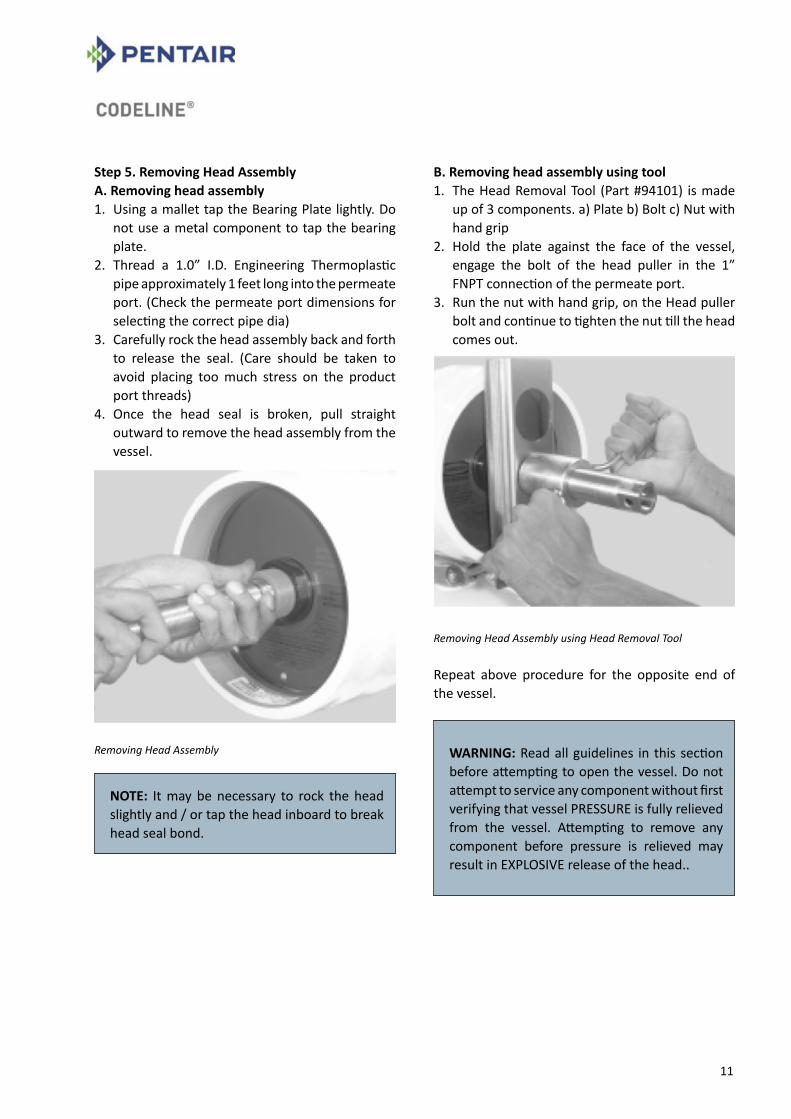
Step 5. Removing Head Assembly A. Removing head assembly 1. Using a mallet tap the Bearing Plate lightly. Do
not use a metal component to tap the bearing plate.
2. Thread a 1.0” I.D. Engineering Thermoplastic pipe approximately 1 feet long into the permeate port. (Check the permeate port dimensions for selecting the correct pipe dia)
3. Carefully rock the head assembly back and forth to release the seal. (Care should be taken to avoid placing too much stress on the product port threads)
4. Once the head seal is broken, pull straight outward to remove the head assembly from the vessel.
Removing Head Assembly
B. Removing head assembly using tool 1. The Head Removal Tool (Part #94101) is made
up of 3 components. a) Plate b) Bolt c) Nut with hand grip
2. Hold the plate against the face of the vessel, engage the bolt of the head puller in the 1” FNPT connection of the permeate port.
3. Run the nut with hand grip, on the Head puller bolt and continue to tighten the nut till the head comes out.
Removing Head Assembly using Head Removal Tool
Repeat above procedure for the opposite end of the vessel.
NOTE: It may be necessary to rock the head slightly and / or tap the head inboard to break head seal bond.
WARNING: Read all guidelines in this section before attempting to open the vessel. Do not attempt to service any component without first verifying that vessel PRESSURE is fully relieved from the vessel. Attempting to remove any component before pressure is relieved may result in EXPLOSIVE release of the head..

12
Replacing Elements
Preliminary Steps DO NOT proceed with step by step instructions until… 1. All pressure has been relieved from the
vessel, following system manufacturer’s recommendations.
2. Both heads have been removed from vessel following step by step instructions in the “Opening the Vessel” section.
Step 1. Remove Element Interface Hardware. 1. Remove thrust cone from the downstream
(concentrate) end. 2. Remove adapters from elements at each end.
Step 2. Element Removal 1. Remove elements from the vessel following
element manufacturer’s instructions. Clean off any excess lubricant from vessel inside diameter before removing elements.
Step 3. Element Loading 1. Examine the inside diameter of the vessel for
scratches or imperfections that may affect sealing capability of head or element seals. Corrosion deposits or other foreign matter, including any excess lubricant, should be removed as described in Section – Closing the Vessel.
2. Flush out the vessel with clean water to remove any dust and debris.
Examining for scratches
3. Examine membrane element surfaces for any imperfection which could scratch the vessel bore. Pay particular attention to edges of anti-telescope device (ATD/brine seal carrier).
4. Using an approximate 50% mixture of glycerine in water, lubricate the inside of the vessel. This may best be accomplished using a suitably sized swab soaked in the mixture. This procedure will ease membrane element loading and reduce chance of scratching the vessel bore.
IMPORTANT: Read all parts of this section before replacing elements. These procedures are provided for general information only. Elements should be installed in accordance with the element manufacturer’s recommendations. Always remove and install elements in the direction of feed flow. The feed end (upstream end) is the end plumbed most directly to the pump. A record of element serial numbers and locations should be made and checked during loading. Do not scratch or damage vessel bore when removing or installing elements.
NOTE: If the brine seal is not installed on the element and the element supplier does not specify otherwise, a brine seal should be placed on the upstream end of the elements. Open side of a seal must face upstream.
13
5. Load the first element into the upstream end of the vessel. Leave a few inches of the element projecting from the vessel to facilitate interconnection to the next element.
6. Apply a light film of a non-petroleum based lubricant, such as Parker Super O-Lube®, to the interconnector O-ring. (The amount of O-Lube should be just enough to give a lustre to the O-ring. Excess O-lube must be removed to prevent possibility of element contamination).
7. Assemble the interconnector to the loaded element.
8. Line up the next element to be loaded and assemble it to the interconnector already assembled on the first element.
9. Push both elements into the vessel until a few inches are projecting from the vessel. Repeat loading process until all elements are installed.
10. When the final element is installed, push the element stack forward until the face of the first (downstream) element is just short of counter bore ramp.
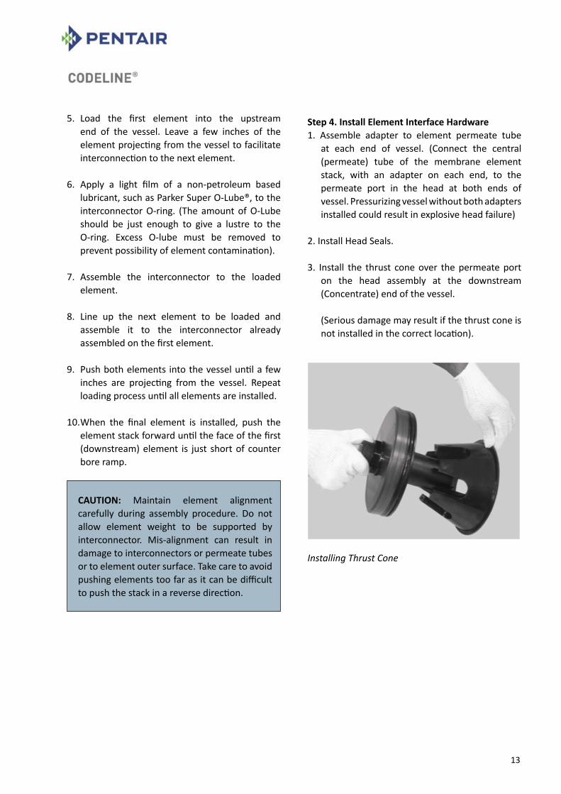
Step 4. Install Element Interface Hardware1. Assemble adapter to element permeate tube
at each end of vessel. (Connect the central (permeate) tube of the membrane element stack, with an adapter on each end, to the permeate port in the head at both ends of vessel. Pressurizing vessel without both adapters installed could result in explosive head failure)
2. Install Head Seals.
3. Install the thrust cone over the permeate port on the head assembly at the downstream (Concentrate) end of the vessel.
(Serious damage may result if the thrust cone is not installed in the correct location).
Installing Thrust Cone
CAUTION: Maintain element alignment carefully during assembly procedure. Do not allow element weight to be supported by interconnector. Mis-alignment can result in damage to interconnectors or permeate tubes or to element outer surface. Take care to avoid pushing elements too far as it can be difficult to push the stack in a reverse direction.

14
Closing the vessel
Preliminary StepsDO NOT proceed until… 1. Elements and adapters have been installed in
the vessel following guidelines in “Replacing the Elements” section.
2. Head has been checked for correct component assembly by following step-by step instructions in the Head Rebuilding section.
3. Vessel has been shimmed to prevent movement of the membrane elements if required. See Trouble Shooting section for a description of when shimming is required.
Cleaning inside the vessel
Step 1. Inspect Shell Inside Surface 1. Inspect the vessel inside surface for any
corrosion deposits or other foreign matter. If any are found, clean the surface as follows:
Using a medium or finer grade of ScotchBriteTM
and a mild soap solution, clean each end of the vessel inner surface upto 8” from each end of the vessel. Rinse away all loosened deposits from the shell inside surface using clean fresh water.
2. Inspect the vessel inside surface for scratches or other damage that could cause leaks. Vessels that leak must be replaced.
3. Inspect Feed/Concentrate port seals and attachments for internal and external damage or deterioration.
Step 2. Shell & Head Lubrication 1. Work O-ring lubricant into shell area behind the
retaining ring groove and approximately 1/2” into the vessel I.D.
2. Ensure entire head seal is covered with a thin layer of O-ring lubricant, with no dirt or dust contamination.
* Contact Pentair Water for guidance if damage to the vessel’s internal surface or Feed/Concentrate port, seals or attachments are discovered during inspection.
WARNING: Read all guidelines in this section before attempting to close the vessel.
CHECK THE HEAD ASSEMBLY FOR CORROSION AS DESCRIBED IN THE HEAD REBUILDING SECTION. CORRODED PARTS CAN RESULT IN CATASTROPHIC FAILURE. Do not pressurize vessel until after visual inspection to ensure that retaining ring is fully seated. Never attempt to repair a fiberglass shell.
WARNING: Any remaining lubricant should be cleaned from the vessel bore before applying fresh lubricant. Glycerine is a commercially available lubricant that will not foul membranes.
15
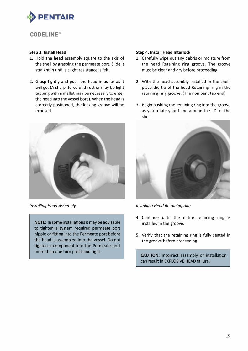
Step 3. Install Head 1. Hold the head assembly square to the axis of
the shell by grasping the permeate port. Slide it straight in until a slight resistance is felt.
2. Grasp tightly and push the head in as far as it will go. (A sharp, forceful thrust or may be light tapping with a mallet may be necessary to enter the head into the vessel bore). When the head is correctly positioned, the locking groove will be exposed.
Installing Head Assembly
Step 4. Install Head Interlock 1. Carefully wipe out any debris or moisture from
the head Retaining ring groove. The groove must be clear and dry before proceeding.
2. With the head assembly installed in the shell, place the tip of the head Retaining ring in the retaining ring groove. (The non bent tab end)
3. Begin pushing the retaining ring into the groove
as you rotate your hand around the I.D. of the shell.
Installing Head Retaining ring
4. Continue until the entire retaining ring is installed in the groove.
5. Verify that the retaining ring is fully seated in the groove before proceeding.
NOTE: In some installations it may be advisable to tighten a system required permeate port nipple or fitting into the Permeate port before the head is assembled into the vessel. Do not tighten a component into the Permeate port more than one turn past hand tight.
CAUTION: Incorrect assembly or installation can result in EXPLOSIVE HEAD failure.

16
Step 5. Reconnect Permeate Piping 1. Reconnect manifold piping to the vessel Permeate port. Using teflon tape or anaerobic sealant on all threaded connections will help ensure a leak-free assembly.
Step 6. PRE_PRESSURIZATION CHECKS It is vitally important that the following checks be carried out before any attempt is made to pressurize the vessel. It is recommended that the Pre-Pressurization Checklist (page 05) be used to systematically verify that all steps have been performed.
HEAD ASSEMBLY Verify the following at each end of the vessel: 1. Head assembly is in good condition, with no
evidence of damage or corrosion. See the sections on Head Rebuilding and Maintenance.
2. Port nut is snug (left-hand thread). 3. Head retaining Ring is properly placed.
MEMBRANE ELEMENTS Verify that… 1. Elements are installed in the vessel. 2. Element adapters are installed at each end of
the vessel. 3. Thrust cone is installed at downstream end of
the vessel.
PIPING CONNECTIONS 1. Check all piping connections to ensure that they
will provide a leak-free seal.
Step 7. Pressurization 1. After following the above pre pressurization
checks, pressurize vessel in accordance with element manufacturer’s specifications.
2. Vessels should be filled slowly to assist trapped air in escaping.
3. Vessels should be pressurized slowly to avoid damage to membrane elements and vessel components.
CAUTION: Do not tighten a component into permeate port more than one turn past hand tight. DO NOT PRESSURIZE THE VESSEL WITHOUT ELEMENTS INSTALLED.Do not pressurize vessel until verifying that the Head Retaining Ring is properly installed.

17
Head - dis-assembling & assembling
Single Piece Engineering Thermoplastic Head (80S15 / 30 / 45 / 60 Non-Coded)
Coded Head Components -disassembled Model : 80S & 80H
Preliminary Steps Do not proceed until… 1. All pressure has been relieved from the
vessel, following system manufacturer’s recommendations.
2. Head has been removed from the vessel following guidelines in “Opening the Vessel” section.
To dis-assemble head Step 1. Removing Adapter 1. Remove the Membrane Adapter from the
permeate port. Grasp the end of the adapter in one hand and the bearing plate in the other and pull them apart.
Removing the Adapter Note : It may be necessary to twist the two parts in opposite directions to break a seal between them.
NOTE: Read all guidelines in this section before attempting to rebuild the head. Head rebuilding should be performed in a clean work area. Dust or dirt on O-rings or other parts can scratch inner surfaces and cause subsequent leakage. Replace any components not in “as-new” condition. Re-using corroded or damaged components can result in explosive head failure.

18
2. Remove the O-ring(s) from the Permeate port adapter.
* Following Steps 2 – 5 are applicable only for Code head.
Step 2. Removing Permeate Port Nut 1. Remove the permeate port nut located on the
external side of the bearing plate by rotating it CLOCKWISE. Note that the port nut has LEFT hand threads.
Removing the Permeate Port Nut
Step 3. Removing Bearing Plate
Removing the Bearing Plate
1. Bearing Plate is held in the assembly by Port Nut, once the port nut is removed the bearing plate is free to remove.
Step 4. Removing Sealing Plate 1. Remove the Sealing Plate by pressing it out from
threaded end of the permeate port.
Removing the Sealing Plate
Step 5. Removing Permeate Portal 1. Using a small screw driver or similar tool remove the permeate port seal. However, do not damage the sealing surface in any way as it may lead to leakage.
Removing the Permeate Port seal
NOTE: A small screw driver or similar tool may be used to remove the O-rings. However, do not damage the sealing surfaces in any way or leakage may result. It is recommended that all seals be replaced each time the head is assembled.
19
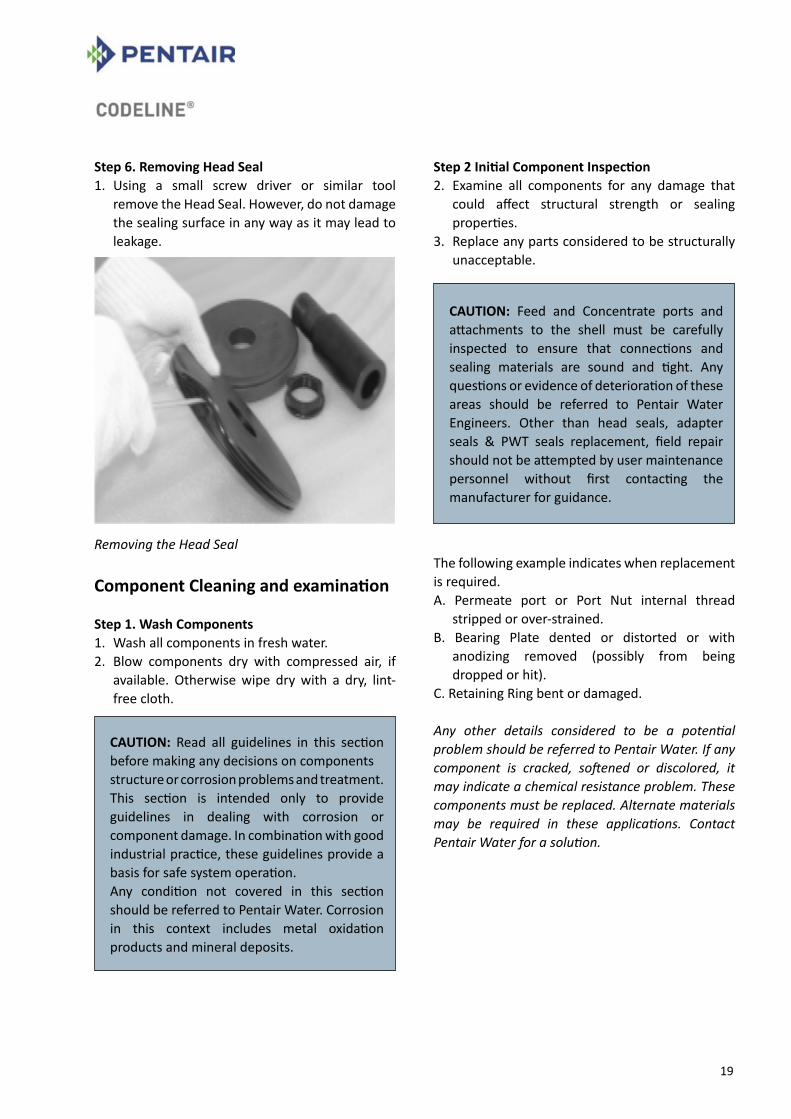
Step 6. Removing Head Seal 1. Using a small screw driver or similar tool
remove the Head Seal. However, do not damage the sealing surface in any way as it may lead to leakage.
Removing the Head Seal
Component Cleaning and examination
Step 1. Wash Components 1. Wash all components in fresh water. 2. Blow components dry with compressed air, if
available. Otherwise wipe dry with a dry, lint-free cloth.
Step 2 Initial Component Inspection 2. Examine all components for any damage that
could affect structural strength or sealing properties.
3. Replace any parts considered to be structurally unacceptable.
The following example indicates when replacement is required. A. Permeate port or Port Nut internal thread
stripped or over-strained. B. Bearing Plate dented or distorted or with
anodizing removed (possibly from being dropped or hit).
C. Retaining Ring bent or damaged.
Any other details considered to be a potential problem should be referred to Pentair Water. If any component is cracked, softened or discolored, it may indicate a chemical resistance problem. These components must be replaced. Alternate materials may be required in these applications. Contact Pentair Water for a solution.
CAUTION: Read all guidelines in this section before making any decisions on componentsstructure or corrosion problems and treatment.This section is intended only to provide guidelines in dealing with corrosion or component damage. In combination with good industrial practice, these guidelines provide a basis for safe system operation.Any condition not covered in this section should be referred to Pentair Water. Corrosion in this context includes metal oxidation products and mineral deposits.
CAUTION: Feed and Concentrate ports and attachments to the shell must be carefully inspected to ensure that connections and sealing materials are sound and tight. Any questions or evidence of deterioration of these areas should be referred to Pentair Water Engineers. Other than head seals, adapter seals & PWT seals replacement, field repair should not be attempted by user maintenance personnel without first contacting the manufacturer for guidance.

20
Step 3. Evaluating Corroded Metal Components
This procedure applies to the following parts: A. Bearing Plate B. Retaining Ring
1. Examine these components for corrosion. For any components not in “as-new” condition, proceed as follows:
A. Loosen any large deposits with small wire brush. B. Place components in shallow container of
soapy water and scrub entire surface with medium grade ScotchBriteTM until all corrosion is removed.
C. Rinse components clean with fresh water. D. Blow components dry with compressed air, if
available. E. Re-examine components for damage that could
affect structural strength or sealing properties. Any components not in “as new” condition must be replaced.
F. Inspect components for any condition that might have promoted corrosion, (e.g. external damage, inappropriate material selection, etc.)
Step 4. REMOVING DEPOSITS FROM Engineering Thermoplastic Components
This procedure applies to the following components: A. Port Nut B. Permeate Port C. Sealing Plate D. Adapter E. Thrust Cone
1. Examine all plastic components for mineral deposits or other foreign matter. If any are found, proceed as follows:
A. Place components in a shallow container of soapy water and scrub entire surface with medium grade ScotchBriteTM until all foreign matter is removed.
B. Rinse components clean with fresh water. C. Blow components dry with compressed air, if
available. D. Re-examine components for any damage
that could affect structural strength or sealing properties. Any components not in “as-new” condition must be replaced.
CAUTION: This procedure for evaluating corroded components is to be used on any corroded metal parts. If this fails to bring any component to “as-new” standards, the part must be replaced.
CAUTION: The following procedure should be used on all Engineering Thermoplastic Components contaminated by minerals or other foreign matter. If any component cannot be brought to “as-new” standards, it must be replaced.

21
To Re-Assemble Head
Step 1. Lubricate and Install Seals
Lubricating Head Seals & O-rings
1. Lubricate and Install permeate port seal in the inner groove of the sealing plate.
2. Lubricate and Install Head Seal on the outer groove of the sealing plate.
3. Lubricate and install Adapter seal on the permeate port end of the Adapter.
4. Lubricate and Install PWT seal on the product water tube end of the adapter.
Installing Permeate Port Seal
Installing Head Seal
WARNING: Head must be carefully assembled following these instructions. Incorrect assembly can result in CATASTROPHIC failure.
CAUTION: It is recommended that all seal be replaced each time the head is assembled. A seal replacement kit is available from Pentair Water. Lubricate seals sparingly, using non petroleum based lubricants, i.e. Parker Super O-lube®, Glycerine or suitable silicone based lubricants. (Silicone based lubricants, correctly used, will ease head assembly and disassembly). (Glycerine is a commercially available lubricant that will not foul membranes).
22
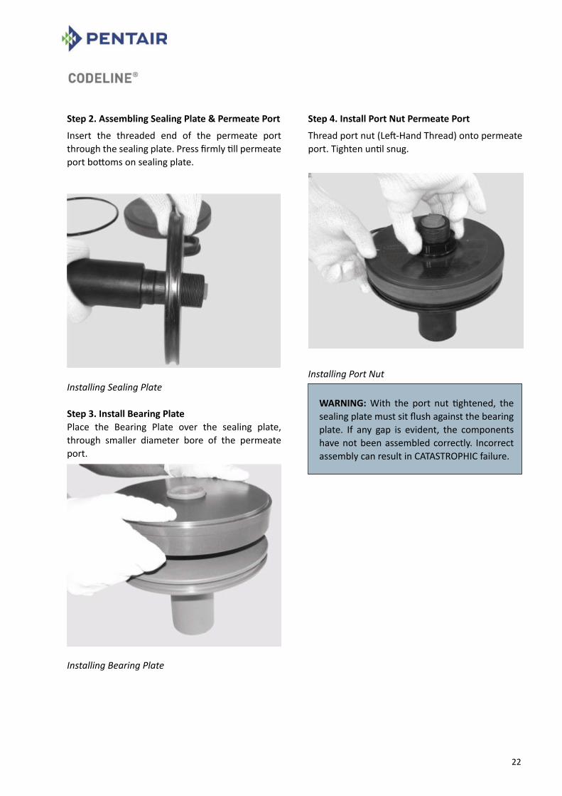
Step 2. Assembling Sealing Plate & Permeate Port
Insert the threaded end of the permeate port through the sealing plate. Press firmly till permeate port bottoms on sealing plate.
Installing Sealing Plate Step 3. Install Bearing Plate Place the Bearing Plate over the sealing plate, through smaller diameter bore of the permeate port.
Installing Bearing Plate
Step 4. Install Port Nut Permeate Port
Thread port nut (Left-Hand Thread) onto permeate port. Tighten until snug.
Installing Port Nut
WARNING: With the port nut tightened, the sealing plate must sit flush against the bearing plate. If any gap is evident, the components have not been assembled correctly. Incorrect assembly can result in CATASTROPHIC failure.

23
Preventive maintenance
Corrosion prevention is essential for the maintenance of safe operating conditions and to ease membrane element servicing. Attention to the points listed below will enhance long-term safe operation and will ease servicing.
For suggestions on cleaning corrosion deposits from the vessel inside surface, refer to “Closing the Vessel” section.
For suggestions on cleaning corrosion deposits from head components, refer to the “Head -Dis assembling & Assembling” section.
Preventive checklist
n End closures. Inspect for components that may have deteriorated. Replace as needed.
n Keep external head assembly components as dry as possible.
n Do not tolerate leaks.
CAUTION: Any leakage indicates a potentially dangerous condition. Failure to eliminate leakage may void the warranty and could result in vessel failure.

24
Trouble shootingThis section is intended only to provide guidelines for dealing with problems that might arise while working with CodeLine® OCTA Series pressure vessels. These guidelines are not in any way a replacement for the good industrial practice required to ensure safe operation. We recommend that only a qualified engineer, experienced in servicing high pressure hydraulic systems, carry out the following tasks.
Preliminary Inspection Inspect the vessel at each end for corrosion which may interfere with head assembly removal. If corrosion is evident, proceed as follows: 1. Loosen any deposits with a small wire brush
and/or a medium grade piece of ScotchBriteTM.
Loosening Deposits
2. Flush away loosened deposits with clean water.
3. Proceed with instructions given in “Opening the Vessel” section.
Difficulty in Opening Vessel
Head Retaining Ring1. Will not release from the Retaining Ring Groove. A. Apply penetrating fluid (such as WD-40 or LPS-1)
to interfacing areas of retaining ring. B. With a screwdriver handle or similar tool, tap
the retaining ring to release the bond. C. Again attempt to remove the retaining ring.
Applying penetrating fluid
WARNING: Do not use a wire brush on components made from Engineering Thermo-plastic.
NOTE: Recommendations listed here are intended only as a guide. If the head assembly is still difficult to remove after all recommendations have been followed, call Pentair Water for technical assistance.
CAUTION: When applying penetrating fluid, be careful to avoid element contamination.

25
Head Assembly1. Will not release from shell when pulled. A. Using a head removal tool, fix the 1” NPT
connection to the permeate end and tighten the nut till the head comes out.
OR B. Thread a 1” ID Engineering Thermoplastic pipe
approximately 1 feet long into the permeate port.
Carefully rock the head assembly back and forth to release the seal. Once the head seal has been broken, complete removal as instructed in the “Opening the Vessel” section.
Freeing Head Seal
Seal leakage 2. Head Seal Leak A. Carefully inspect the seal gland area in the shell
and clean any contaminants from the gland. B. Clean the seal area on the head and re lubricate. C. Install a new head seal that has been properly
lubricated. 3. Permeate Port Leak A. Loosen the Port nut. Once the port nut is
loosened the complete head assembly can be easily dismantled.
B. Permeate port seal is seated in the sealing plate. Run your fingers around the seal and check for any seal damage. If the seal is damaged replace the seal.
C. Check for any damage/scratches on the Permeate port sealing area. Replace the permeate port if found damaged.
Sealing Plate & Permeate Port Seal
3. Feed/Concentrate Port Leak
NOTE: If the head assembly will not release from the shell after all recommendations have been followed, call Pentair Water for technical assistance.
IMPORTANT: Please contact Pentair Water if any Feed/Concentrate leaks are observed.
26
Sudden Drop in Permeate quality If a system is started and stopped frequently and no provision is made to raise the pressure slowly, movement of the membrane column may damage O-ring seals and reduce permeate quality. If the quality of the permeate suddenly drops, and poor membrane performance is not suspected, remove the heads per instructions in the Users Guide (See “Opening the vessel” section on page 10). Inspect these O-ring seals carefully for breakage or other damage. If the seals have rolled out of the groove, or are damaged, this may indicate excessive movement during start-up and shutdown. To overcome this problem, the vessel should be shimmed to minimize this movement. Follow the procedure for shimming as given below:
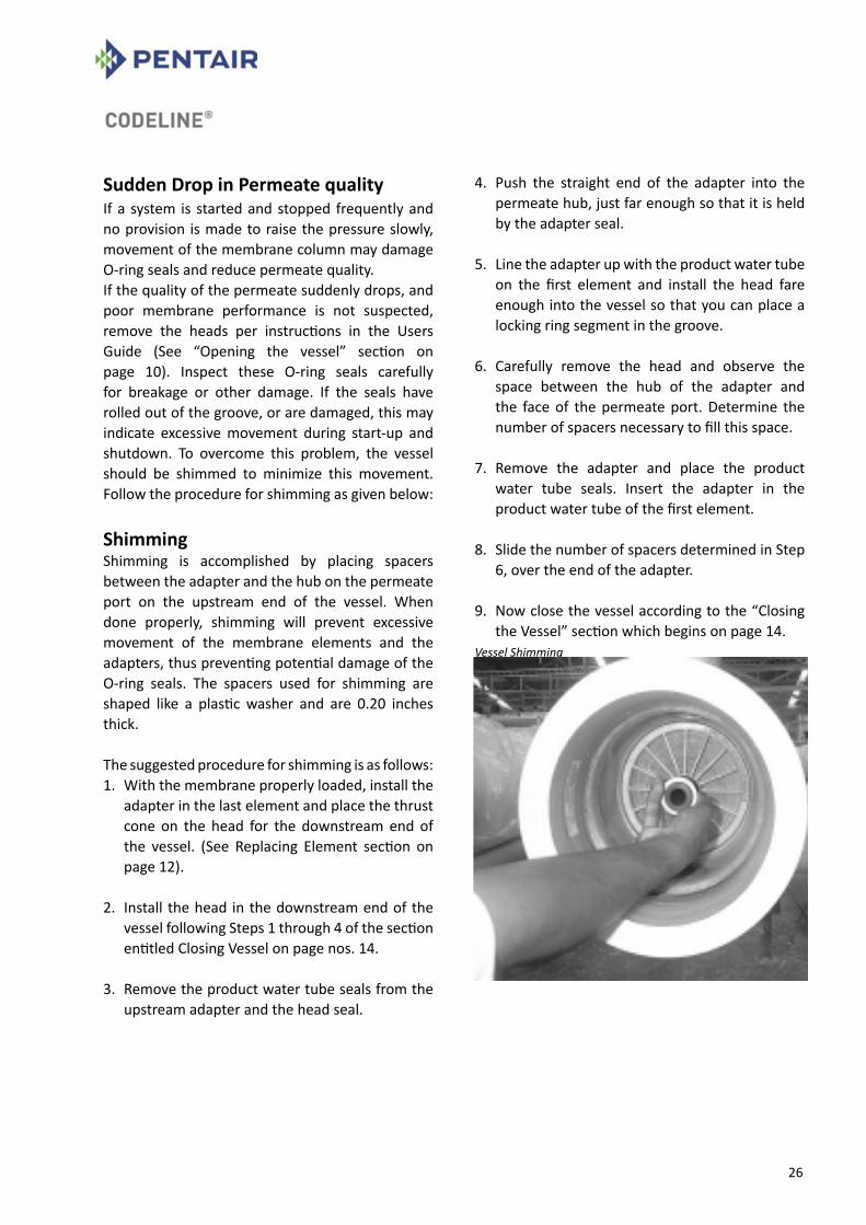
Shimming Shimming is accomplished by placing spacers between the adapter and the hub on the permeate port on the upstream end of the vessel. When done properly, shimming will prevent excessive movement of the membrane elements and the adapters, thus preventing potential damage of the O-ring seals. The spacers used for shimming are shaped like a plastic washer and are 0.20 inches thick.
The suggested procedure for shimming is as follows: 1. With the membrane properly loaded, install the
adapter in the last element and place the thrust cone on the head for the downstream end of the vessel. (See Replacing Element section on page 12).
2. Install the head in the downstream end of the vessel following Steps 1 through 4 of the section entitled Closing Vessel on page nos. 14.
3. Remove the product water tube seals from the upstream adapter and the head seal.
4. Push the straight end of the adapter into the permeate hub, just far enough so that it is held by the adapter seal.
5. Line the adapter up with the product water tube on the first element and install the head fare enough into the vessel so that you can place a locking ring segment in the groove.
6. Carefully remove the head and observe the space between the hub of the adapter and the face of the permeate port. Determine the number of spacers necessary to fill this space.
7. Remove the adapter and place the product water tube seals. Insert the adapter in the product water tube of the first element.
8. Slide the number of spacers determined in Step 6, over the end of the adapter.
9. Now close the vessel according to the “Closing the Vessel” section which begins on page 14.
Vessel Shimming

27
INSTALLATION GUIDE
Introduction The CodeLine® OCTA Series fiberglass membrane housing is designed for continuous long term use as a housing for reverse osmosis, nano-filtration, ultra-filtration and micro-filtration elements in typical water treatment systems at operating pressures of 75 PSI to 1200 PSI.
The CodeLine® OCTA Series is designed to accommodate any make of 8-inch nominal diameter membrane element.
Improper assembly, misuse, rigid clamping, impact, scratches, abrasion or corrosion can result in mechanical failure, property damage and serious injury or death.
The information and guidelines incorporated in this User’s Guide are intended only as supplement to good industrial practice. Full responsibility for correct operation and maintenance of vessel remains with the user.
This guide should be used in conjunction with engineering drawings.
When properly installed and maintained, the CodeLine® OCTA Series vessels can be expected to provide safe operation over a long service life.
Should any information in this guide not agree with the system supplier’s instructions, call Pentair Water for clarification.
NOTE Regardless of when and by whom your vessel may have been installed, there are a fewquick checks you should make before use. Check that each vessel is:
• Mounted with compliant material (Polyurethane Saddle) between the fiber-glass shell and any rigid frame.
• Free to expand under pressure – shell not clamped rigidly in place, no rigid piping connection to port fittings.
• Not used in any way to support other vessels / objects.
28
Handling, receiving and storageFiberglass reinforced plastic (FRP) Pressure vessels are extremely rugged and durable. They are designed for safe, long-term service when they are handled and installed properly. However, damage to the vessel shell or related components from improper handling or installation could result in malfunction or explosive head failure while in service. Therefore exercise the following precautions whenever handling vessel.
1. Never lift or move a vessel by placing anything inside it. The vessel is durable and ideally suited to its purpose, but careless handling can permanently damage it.
2. Be careful not to scratch the inside wall of the shell, especially in the sealing area inboard of locking segment groove near the end.
3. Do not drop vessel or allow it to hit hard on the ground or against other objects.
4. Do not apply undue stress to shell.
5. Before using a forklift to handle the vessel, pad the forks to lessen the chance of damaging the shell. Severe scratches or gouging of the vessel can result in failure of the vessel wall.
6. Do not allow undue stress to act on the Feed/Concentrate port, which might cause impact damage to the port area, leading to leakage. Do not use the Feed/Concentrate port or the permeate port as a tool to lift the pressure vessel or as a support to manifolds. Manifolds should be self-supporting.
Storage Pentair Water recommends storing the vessel in the received packing or in a secure place. Vessel should not be stored in such a manner that they will roll over and get damaged.
NOTE ON IMPACT DAMAGE Exterior vessel damage can lead to early vessel failure. Damage received in shipment should be reported to the shipping company immediately upon receipt minor damage such as scratches that go no deeper than the paint may be acceptable. Call the Pentair Water customer service department for advice if in doubt.

29
Mounting shell & piping connection
This section is concerned with the mounting of CodeLine® Models 80S & 80H pressure vessels. These guidelines must be integrated with any additional procedure required for your specific installation.
Installation Guidelines 1. Provide adequate room for servicing at both
ends of vessel. Elements are installed from the upstream end (feed), pushed through towards the downstream end (concentrate) and, eventually, removed from the downstream end.
2. Follow all applicable Handling Guidelines. 3. Position each vessel on its mounting frame such
that it is centered between headers.
4. Mount vessels on urethane saddles (provided with the vessel) positioned in line with pre drilled frame holes for –1 through –3 vessels. Holes for the mounting straps should be drilled at approximate center span ‘S’. For –4 and –8 vessels, holes for the mounting straps should be drilled at span ‘S’ from the middle of the vessel and a third saddle, without a strap, should be placed at mid span. These dimensions are shown on the corresponding engineering drawing.
NOTE: If mounting vessel for the first time, see “piping recommendations for CodeLine® side-port vessel”, page no, 35
NOTE: It is important that each vessel be placed to minimize any strain on piping / tubing that connects a vessel to a header. Normally each vessel should be centered in the frame with the feed and concentrate ports positioned such that piping / tubing connections can be made easily, without undue strain at each end of the vessel.
WARNING: Do not mount vessel rigidly. restricted expansion can result in damage to the vessel. see elasticity and mounting requirements in the application section for further details.

30
5. Place mounting straps over vessel with plastic strip against vessel.
6. Position screw through the frame mounting holes into strap nuts and run up to the frame finger tight.
7. Connect vessel feed piping (See Piping Recommendations for more info)
8. Using a wrench, tighten mounting bolts one additional full turn. This should result in 25-50 lbs in. of torque.
Piping connections
The following are suggested guidelines to ensure that the vessel is allowed to expand and is easily serviced:
1. Support the header and interconnecting piping in a manner that they are self-supporting.
2. Connecting piping alignment to feed, concentrate and permeate ports should not exceed 0.030 inch (0.762 mm) misalignment.
3. Piping connections to the vessel’s feed / concentrate ports should be via flexible IPS grooved Coupling.
CAUTION: To avoid damage to vessel shell, DO NOT over-tighten mounting nuts.
WARNING: CodeLine® straps are designed to secure the vessels during operation. They are not designed to handle all loads that might occur during shipment. Appropriate vessel restraint should be employed considering such factors as the mode of shipment, distance to be traveled and design of the system. The vessels and frame should be blocked to prevent any differential movement which could be caused by the forces experienced during shipment.
31
Application guideIntroduction
This Application Guide, together with the Installation Guide and the Operation and Maintenance Guide, outlines the general conditions for safe use of CodeLine® Side-ported pressure vessels. Because of the considerable risk inherent in high pressure vessels, it is the purchaser’s responsibility to carefully evaluate each specified application to ensure that the CodeLine® Side ported vessel selected is appropriate to that application.
Pentair Water will assist the purchaser in determining the suitability of the standard vessel for their specific operating conditions. For non-standard applications, alternate materials are available on special order. The final determination, however, including evaluation of the standard materials of construction for compatibility with the specific environment, is the responsibility of the purchaser.
Suitability for intended use CodeLine® OCTA Series membrane housings are designed for continuous long-term use as housings for reverse osmosis, nano-filtration, ultra-filtration and micro-filtration membrane elements. Models are available for 75, 150, 300, 450, 600, 1000 & 1200 psi. Any make of eight inch nominal diameter spiral wound element is easily accommodated.
In a high pressure system there is considerable potential for catastrophic failure, which could result in serious injury or loss of life. All decisions as to suitability for use must include full consideration of the various safety aspects involved. These include, but are not limited to:
• Process fluid compatibility (e.g. chemical and temperature consideration).
External environmental factors (e.g. corrosive atmosphere, remote or special environment where certain material might be undesirable, etc.).
Abnormal back pressure which might result in pressurizing permeate port above the rated pressure (alternate materials are available).
• Capability of the user to maintain vessel properly.
• Requirement for increased fire resistance in some circumstances.
Use of CodeLine® 80S & 80H model pressure vessel for other than its intended application will void the warranty.

32
Elasticity and mounting requirements
Mounting design must allow for vessel expansion, both axially and radially. Although the expansion under pressure is slight, undue restriction can result in damage to the vessel and to other system components. Typically a eight-element vessel, to example, would expand approximately 0.20 inch (5.08 mm) in length and 0.015 inch (0.4 mm) in diameter. The following suggestions will help to ensure the vessel is allowed to expand and will ease servicing.
1. Mount the vessel on the urethane support pads furnished. Do not mount directly to any rigid structure.
2. Use the stainless steel straps furnished. Straps should be tightened sufficiently to hold the vessel on the urethane support pads, but not so tightly so as to restrict expansion. (A torque of 25-50 lbs-in. is sufficient.)
3. U-bolts should not be used for vessel mounting under any circumstances.
4. Provide flexible piping connection to permit de-coupling the header from the vessel. The recommended Permeate Port connection is a U-bend pipe with flexible connections at each end, or a flexible hose. Recommended Feed and Concentrate connections are via flexible IPS grooved coupling.
5. Do not hard plumb any piping connections to the vessel.
6. Support the header independently. Piping should be self-supporting or supported by the headers.
7. Include an expansion loop in the branch connection to allow for:
A. Elastic growth under pressure. B. Thermal growth in vessel length.
8. The total weight of branch connection and fittings supported by the vessel should not exceed 8 lbs for either the Feed / Concentrate ports or the Permeate port for CodeLine® 80S & 80H model vessels.
The above suggestions are intended to help prevent damage in typical applications. Unusual or special applications may involve other considerations to be determined by the system designer.
33
CorrosionConsiderations relating to corrosion are an important factor in vessel application. Corrosion can result in catastrophic failure and / or cause difficulty in removing head components from the shell. Correct component material selection is essential for safe long-term use. Although the process fluid is the main consideration, external environment conditions should also be taken into account.
All reasonable precautions should be taken to protect head assemblies from external wetting, particularly in corrosive atmospheres (e.g. salt-water areas or acid atmosphere such as near lead acid battery arrays, etc.) Leaks from vessel or nearby components, which allow head parts to be routinely wetted, should not be tolerated. The following typical list of CodeLine® model 80S & 80H pressure vessel components indicating the standard material of construction of each part is listed from page nos. 6 – 9. An evaluation of the possibility of corrosion damage to the metal head interlock components is of critical importance. Alternate materials are available upon requests.
Safety
Safety in service of fiberglass vessel depends on proper application, installation, operation and maintenance. This section is intended to provide guidance towards safe system design. The safety information given in the installation and operation and maintenance section should also be studied and used appropriately in conjunction with the precautions listed below.
Design Considerations for Safety
Fluid Compatibly The materials of construction selected must be compatible with the process fluid and with proposed preserving and cleaning fluids. Standard materials are listed on the engineering drawings. In case where the standard materials are unacceptable, suitable alternative may be available.
Pressure and Temperature design limits Operation of a vessel outside its design limits will void the warranty and would result in vessel fatigue with possible eventual catastrophic failure. Although each CodeLine® 80S & 80H model vessel is tested as per ASME/CE specifications, long term operation above the designed pressure must be prevented. For permeate port pressure rating and maximum operating temperature, refer respective sales drawings.
Over pressure protection It is essential that over pressure protection be provided such that the pressure to which any vessel is subjected cannot exceed 105% of design pressure.
Mounting The pressure vessel should not be used as a support. Piping manifolds and other fittings should be supported by properly designed system framework. Operating personnel should be discouraged from applying from undue force to any fittings connected directly to a pressure vessel.
Accessibility Pressure vessel should be positioned within the system such that elements can be inserted at the upstream end and removed from the downstream end (i.e. elements are installed and removed in the direction of feed flow).
CAUTION: Pressure vessel may cause loss of life, severe bodily harm or property damage if not correctly installed, operated and maintained.
34
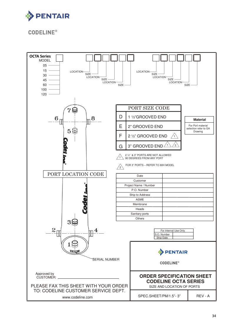
36
D
E
F
1 ½”GROOVED END
2” GROOVED END
2 ” GROOVED END½
ORDER SPECIFICATION SHEETCODELINE OCTA SERIES
SIZE AND LOCATION OF PORTS
SPEC.SHEET/PM/1.5”- 3” REV - A
SERIAL NUMBER
Approved by CUSTOMER:
PLEASE FAX THIS SHEET WITH YOUR ORDERTO: CODELINE CUSTOMER SERVICE DEPT.
1
MODEL
15
30
45
60
100
120
LOCATIONSIZE
LOCATIONSIZELOCATION
SIZE
LOCATIONSIZE
LOCATION SIZELOCATION
SIZE
www.codeline.com
Material
For Port material selection refer to GA
Drawing
12 ½” & 3” PORTS ARE NOT ALLOWED 90 DEGREES FROM ANY PORT
Date
Customer
Project Name / Number
P.O. Number
Ship to Address
ASME
Membrane
Heads
Sanitary ports
Others
For Internal Use Only
S.O. Number Ship Date
2FOR 3” PORTS – REFER TO 80H MODEL
G 3” GROOVED END 2
05
1
OCTA Series
35
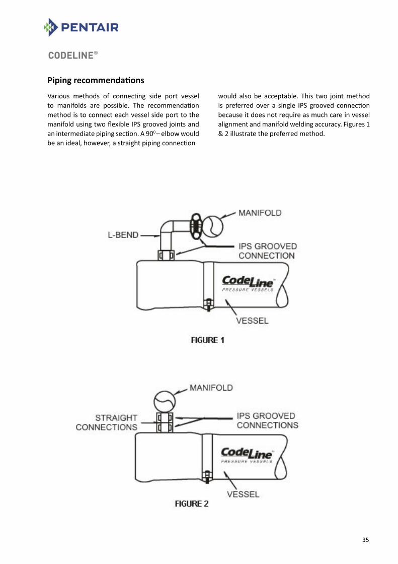
Piping recommendations
Various methods of connecting side port vessel to manifolds are possible. The recommendation method is to connect each vessel side port to the manifold using two flexible IPS grooved joints and an intermediate piping section. A 900 – elbow would be an ideal, however, a straight piping connection
would also be acceptable. This two joint method is preferred over a single IPS grooved connection because it does not require as much care in vessel alignment and manifold welding accuracy. Figures 1 & 2 illustrate the preferred method.
36
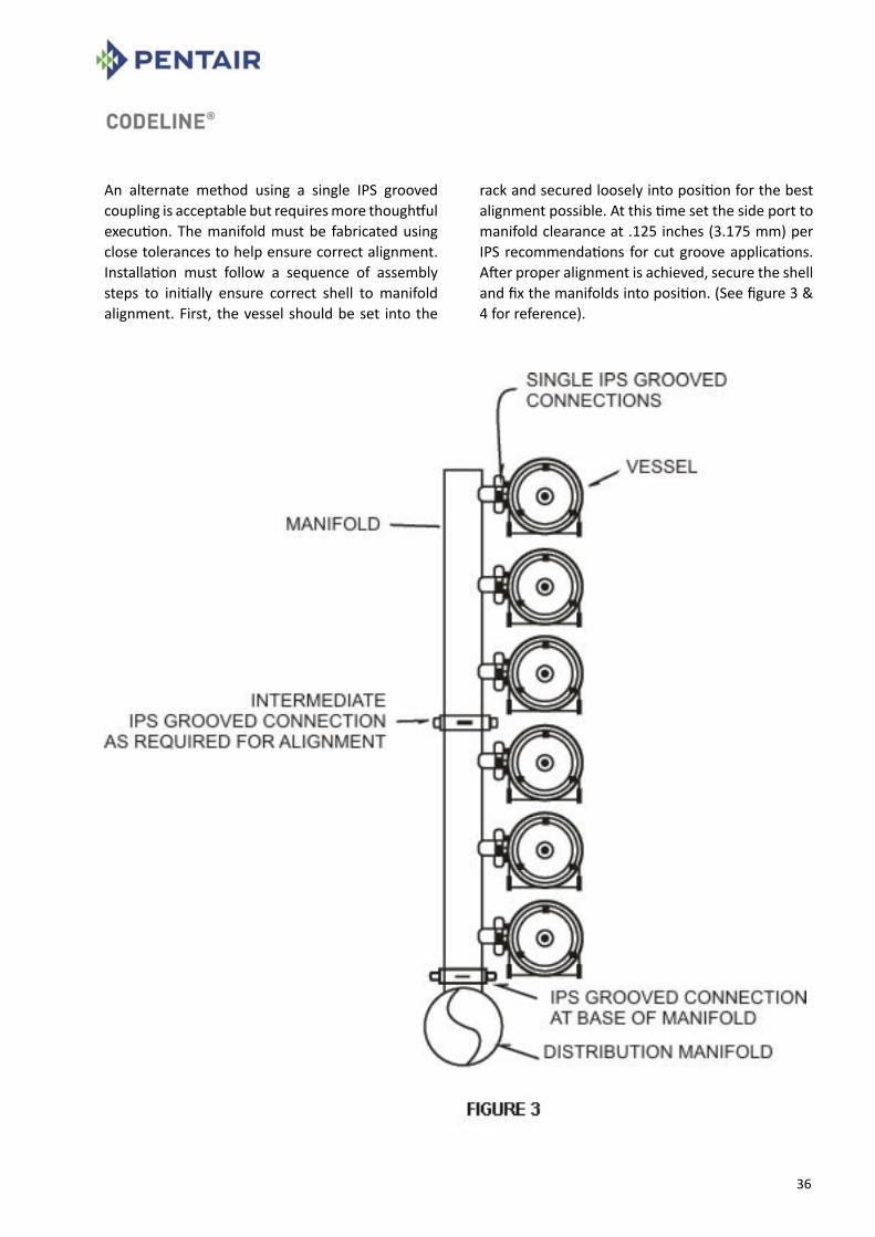
An alternate method using a single IPS grooved coupling is acceptable but requires more thoughtful execution. The manifold must be fabricated using close tolerances to help ensure correct alignment. Installation must follow a sequence of assembly steps to initially ensure correct shell to manifold alignment. First, the vessel should be set into the
rack and secured loosely into position for the best alignment possible. At this time set the side port to manifold clearance at .125 inches (3.175 mm) per IPS recommendations for cut groove applications. After proper alignment is achieved, secure the shell and fix the manifolds into position. (See figure 3 & 4 for reference).
37
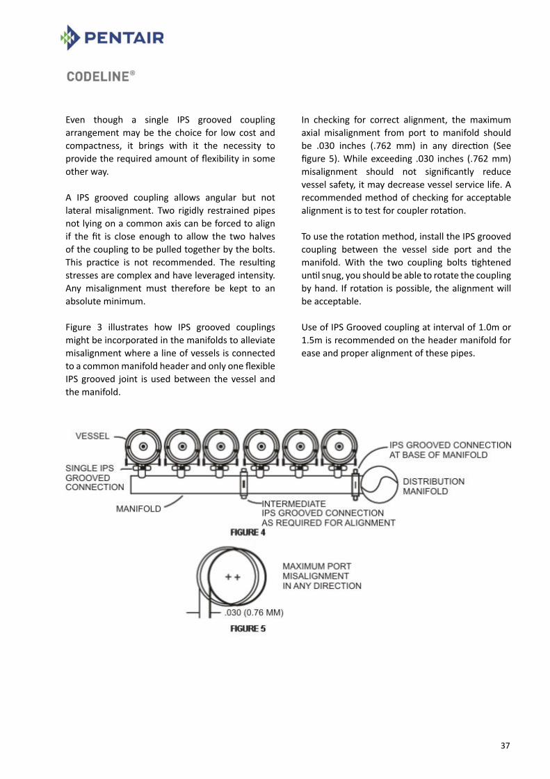
Even though a single IPS grooved coupling arrangement may be the choice for low cost and compactness, it brings with it the necessity to provide the required amount of flexibility in some other way.
A IPS grooved coupling allows angular but not lateral misalignment. Two rigidly restrained pipes not lying on a common axis can be forced to align if the fit is close enough to allow the two halves of the coupling to be pulled together by the bolts. This practice is not recommended. The resulting stresses are complex and have leveraged intensity. Any misalignment must therefore be kept to an absolute minimum.
Figure 3 illustrates how IPS grooved couplings might be incorporated in the manifolds to alleviate misalignment where a line of vessels is connected to a common manifold header and only one flexible IPS grooved joint is used between the vessel and the manifold.
In checking for correct alignment, the maximum axial misalignment from port to manifold should be .030 inches (.762 mm) in any direction (See figure 5). While exceeding .030 inches (.762 mm) misalignment should not significantly reduce vessel safety, it may decrease vessel service life. A recommended method of checking for acceptable alignment is to test for coupler rotation.
To use the rotation method, install the IPS grooved coupling between the vessel side port and the manifold. With the two coupling bolts tightened until snug, you should be able to rotate the coupling by hand. If rotation is possible, the alignment will be acceptable.
Use of IPS Grooved coupling at interval of 1.0m or 1.5m is recommended on the header manifold for ease and proper alignment of these pipes.
38
CodeLine® -Multi-portTM
High Flow Membrane Housings
Your Path to Reducing System Cost by Using Multi-portTM
By now most end users, designers and builders of membrane separation systems are familiar with CodeLine® side-ported FRP housings. With over 100,000 units in service, we have leaded the industry in helping reduce the cost of membrane systems around the world.
As CodeLine® has continued to advance side-porting technology, we have focused on developing products that help further reduce system cost. With this being the case, CodeLine® is proud to announce Multi-portTM Membrane Housings with 3” Port.
What can it do for your system? Multi-porting is a term used to describe membrane housing that feature more than one feed or concentrate port per end. For example, two or three ports in the feed end of a membrane housing. Multi-porting allows vessels to be directly linked together. This powerful feature offers the opportunity to eliminate traditional manifolds resulting in potential system cost savings. While the cost reduction aspect of this technology is enticing, system performance must be carefully evaluated to assure that improper port sizing does not compromise long-term system performance. While using High Flow-ported housing is not difficult, there are many variables that need to be properly addressed before vessels can be specified. To help ensure the performance of your system, please carefully consider the guidelines and pressure drop data on the following pages when attempting to eliminate external manifolds.
Detailed Guidelines for Using Multi-portTM High Flow Membrane Housings to Eliminate Manifolds
Evaluate the pressure drop across each vessel plenum as this will affect the permeate and concentrate flows in each vessel. Typically, the feed and concentrate manifolds connecting to a number of vessels are designed to minimize variations in flow through the vessels. This is accomplished by assuring that the pressure throughout a manifold is nearly equal. The greater the differential across a particular manifold, or set of manifolds, the greater the potential for variations in the average feed pressure as well as the differential pressure across the different vessels in a pass. These factors will affect the flow of the product as well as the flow through the vessels.
The same considerations apply when attempting to eliminate manifolds by linking vessels directly together using Multi-portTM vessels. In this case, the pressure drop across the vessel plenum, as well as the entrance and exit losses through the side ports, must be considered. To simplify this process, we have provided calculated test data, which quantifies the total pressure, drop versus the flow rate for various size ports. Flow balance the system by taking the combined concentrate flow from the last vessel in a particular pass. This practice is commonly used when multiple filters are connected in parallel. If the feed comes in the first vessel, the combined concentrate should exit the last vessel.
CAUTION: The following are Guidelines only. They are intended to aid the Purchaser when using the Multi-portTM feature to eliminate manifolds. It is the system designer’s responsibility to evaluate the specific application and carefully consider these guidelines when sizing ports. Improper port sizing could lead to poor system performance and/or damage to membrane elements. Please contact Pentair Water if clarification of these Guidelines is required.

39
The feed pressure to the last vessel will always be less than the feed pressure to the first vessel. By flow balancing, the concentrate pressure of the last vessel will also be the lowest of any vessel. This tends to keep the pressure drop across all vessels to be as close as possible. The flow pattern is shown in Figure1.
Figure 1 - Flow Balancing
The down side of this arrangement is that it will cause the average feed flow pressure between the first and last vessel to be the at a maximum value, thus affecting permeate flow in the last vessel.
For simplicity of piping, some customers may desire to take combined concentrate flow from the first vessel in a particular pass. This will result in a lower differential pressure and thus a lower concentrate flow in the last vessel. While this practice is less conservative than flow balancing, it has been successfully used in some systems. In any event, the performance of the membranes in each vessel should be checked to confirm that all are within the membrane manufacturer’s guidelines.
Consider feeding from both sides or the center of a pass if the differential pressure when feeding from one side would be excessive. By splitting the feed flow the velocity will be reduced by one half and the pressure drop by an even greater amount since the pressure drop is proportional to the square of the flow. Feeding from both sides may be most economically feasible where the pressure is low enough to use plastic pipe. This option is shown in Figure 2.
Figure 2 - Both Sides
Check with your membrane supplier for evaluation of membrane performance of your proposed system. When properly sized, use of Multi-portTM vessels to eliminate external manifolds will have little if any affect on overall system performance. However, as pressure drops are increased, systems that are already being operated close to the edge of recommended conditions may experience problems within one or more vessels. It is therefore recommended that worst case conditions be evaluated carefully in conjunction with your membrane supplier.
40
Consider the effects of higher velocities that may occur during special situations such as flushing or cleaning. It is sometimes advantageous to flush or clean systems at velocities higher than normal. These situations must be carefully considered when selecting port sizes. Pressure drops may be considerably increased under such conditions. Pressure drops across the plenum of a vessel will always be greater than through an equal length of straight pipe of the same size as the port. For this reason you should always select ports at least equal to, and possibly greater than, the size of pipe you would use if manifolds were external.
Do not reduce the size of the feed/concentrate ports in a particular pass, unless you have carefully evaluated the affect on system performance of such reductions. (For brackish water desalination at the recovery above 65% the brine discharge connection size may be reduced as compared to the feed connection size.)
Unlike with external manifolds, it is easy to reduce the size of ports of vessels, which are linked together. The feed port may be one size and the port directly opposite it can be specified a smaller size. This however could lead to excessive pressure drops. Again, evaluate the affects of such a design carefully.
Do not exceed traditional flow velocities. Even though the pressure drop across each vessel may be acceptable, the velocity of the water through each port must also be evaluated. It is suggested that the water velocity throughout the entire system be checked for proper velocity, however, the first connection from the feed source is typically where problems can occur. While the length of each feed port is very short, velocities in excess of 11 Ft. per second should be avoided to help ensure proper system performance. For your convenience, we have included the published velocities for schedule 40 pipe in this bulletin.
Do not assume, because a set of vessels can be manifolded together, that CodeLine® recommends or endorses such use in your particular application.
Used properly, multi-porting with 3” ports opens up a whole New World of potential cost savings. With this opportunity comes a responsibility to carefully evaluate projected membrane performance. CodeLine® recommends that you work directly with you membrane supplier to obtain approval of your proposed design.

41
© CodeLine 2005 45
CalculatedPressure
Drop
Flow rate V/s Pressure Drop
0
1
2
3
4
5
6
7
8
9
0 50 100 150 200 250 300 350 400 450 500
Flow Rate (GPM) @ 72oF
Pre
ss
ure
Dro
p (
ps
i)
1.5" port
2" port
2.5" port
3" port
Flow Rate V/s Velocity Schedule 40 pipe
0
1
2
3
4
5
6
7
8
9
10
11
12
13
14
15
16
17
18
19
20
21
0 50 100 150 200 250 300 350 400 450 500
Flow Rate(GPM)
Velo
cit
y(f
t/s)
3" Port
2.5" Port
2" Port
1.5" Port

42
Pentair Water – Limited Warranty
Pentair Water India Pvt. Ltd., a division of “Pentair Water” manufactures its products (“Products”) and parts (“Parts”) under the highest standards of workmanship using quality materials. Accordingly, Pentair Water expressly warrants these Products and Parts as follows:
Warranty coverage a) All the “CodeLine” & “Pentair” branded
membrane housing products are warranted to the original owner to be free of defects in material and/or workmanship under normal use for a period of one (1) year from date of Invoice.
b) Any replacement Product or Part provided hereunder will be warranted against defects in material and workmanship for the unexpired portion of the one year warranty period applicable to the goods.
Exclusions from this limited warranty This warranty does not cover: 1. Defects not reported to Pentair Water within
the above described warranty period. 2. Any items manufactured by other companies.
Such items may carry warranties offered by the original manufacturers.
3. Problems resulting from failure to comply with installation instructions or drawings, or improper installation.
4. Damage caused by acts of nature or problems resulting from abuse, misuse, negligence or accident by any party other than Pentair Water.
5. Problems resulting in whole or in part from alteration, modification or attempted repair of these Products or Parts by any party other than Pentair Water.
6. Normal wear of replaceable components, including elastomeric Seals, Spacers etc. These parts require maintenance as part of a yearly service schedule.
7. Non compliance with applicable codes and ordinances including without limitation, plumbing codes.
8. Damage due to chemical attack. 9. Warranty applies only to original owner at the
original installation location
10. Shortages in receipt of spares/components/products not intimated to the seller within 60 days of the receipt by buyer.
Warranty obligations of pentair water Should a defect in workmanship and/or material in Products or Parts covered by this warranty become evident during the term of the warranty, then upon compliance with the procedures, as set forth below, Pentair Water, at its option, will: In the case of Products, issue a credit in the amount of the original purchase price of the product, or repair or replace the defective Products. Pentair Water will consider, in good faith customer preferences in making a determination whether to issue a credit or repair or replace a Product. In the case of Parts, whether purchased new or exchanged on a Product by other parts, Parts may not be returned for credit or repair. Pentair Water will only be responsible for the replacement of defective parts.
Procedure for obtaining warranty performance If the buyer discovers within this period a failure of the product to conform to specifications, or a defect in material or Workmanship, the buyer must promptly notify Pentair Water in writing. In no event may that notification be received by Pentair Water more than 30 days after the end of the warranty period. Any goods that the buyer believes to be defective are to be returned to Pentair Water factory for examination. However, upon request of the buyer, Pentair Water may, at its discretion, agree to examine the goods in the field. If, upon examination by Pentair Water, any goods sold under this agreement or purchase order do fail to conform to CodeLine / Pentair specifications, or prove to be defective in material or workmanship, Pentair Water will supply an identical or substantially similar part F.O.B., Pentair Water factory; or Pentair Water, at its option, will repair such part or give credit to the buyer for the original cost of such goods. However, if the goods were examined in the field and Pentair Water determines that they do conform to CodeLine / Pentair specifications, the buyer will be responsible to pay to Pentair Water, a $750 field service charge, plus travel expenses and a $750 per diem charge.

43
NO OTHER WARRANTIES. To the maximum extent permitted by applicable law, PENTAIR WATER DISCLAIMS ALL OTHER WARRANTIES, WHETHER EXPRESS OR IMPLIED, INCLUDING, BUT NOT LIMITED TO THE IMPLIED WARRANTIES OF MERCHANT ABILITY AND FITNESS FOR A PARTICULAR PURPOSE, with regard to the Product(s), Part(s) and/or any accompanying written materials. This limited warranty gives you specific legal rights. You may have others, which vary from state / jurisdiction to state/jurisdiction. NO LIABILITY FOR CONSEQUENTIAL DAMAGES. To the maximum extent permitted by applicable law, in no event shall Pentair Water be liable for any damages whatsoever (including without limitation, loss of times, inconveniences, expenses such as telephone calls, labor or material charges incurred in connection with the removal or replacement of the Product(s) or Part(s), special, incidental, consequential, or indirect damages for personal injury, loss of business profits, business interruption, loss of business information, or any other pecuniary loss) arising out of the use of or inability to use the defective Product(s) or Part(s), even if Pentair Water has been advised of the possibility of such damages. In any case, Pentair Water entire liability under any provision of this Limited Warranty shall be limited to the amount actually paid for the Product(s) or part(s). PLEASE NOTE: Because some states/jurisdictions do not allow the exclusion or limitation of incidental or consequential damages, the above limitation or exclusion may not apply.
WARRANTIES OR REPRESENTATIONS BY OTHERS - No dealer or another person has any authority to make any warranties or representations concerning Pentair Water or its products. Accordingly, Pentair Water is not responsible for any such warranties or representatives.
OTHER RIGHTS This warranty gives specific legal rights, and other rights may apply.

44
Vessel Model: Serial Numbers Numbers are located at one end of the vessel.
(If you have purchased more than 64 vessels,
please attach the serial nos. separately).
Date of Purchase
OEM Purchased From: (Name/
Address/Tel no.)
___________________________
___________________________
___________________________
___________________________
_________ ________ ________
_________ ________ ________
_________ ________ ________
_________ ________ ________
_________ ________ ________
_________ ________ ________
_________ ________ ________
_________ ________ ________
_________ ________ ________
_________ ________ ________
_________ ________ ________
_________ ________ ________
_________ ________ ________
_________ ________ ________
_________ ________ ________
_________ ________ ________
_________ ________ ________
_________ ________ ________
_________ ________ ________
_________ ________ ________
_________ ________ ________
_________ ________ ________
Treatment System wherein used:
(Please circle the relevant)
RO UF
NF Other
System Capacity:_________GPD
No. of Vessels: __________
Date of Installation:___________
Name/Address/Tel & email of
your Company:
___________________________
___________________________
___________________________
___________________________
Installation Site:
(Address/Country)
___________________________
___________________________
___________________________
___________________________
Mailing Address: CodeLine Division
Pentair Water India Pvt. Ltd.
L/52-55, Verna Industrial Area
Verna, Goa – 403 722. INDIA
Tel: 91-832-2883300
Fax: 91-832-2883312
www.codeline.com
PENTAIR WATER
REGISTRATION CARD
Thank you for purchasing a world class CodeLine® vessel. To help us service you better
and update you on “improvement and changes”, please fill up the above registration card
and mail at the address given in the same.

45
Disclaimer : All information included in this publication is based on the latest information available at the time of printing. Pentair reserves the right to make changes at any time without notice and without incurring any obligation whatsoever. Photocopying of this publication by authorized original equipment manufacturers who have purchased directly from Pentair, or by persons using the materials for legitimate educational purposes, is approved by Pentair. Otherwise all copyright protection afforded by the law applies.UG CODELINE 80S H EN 5115 @2015 PENTAIR. All Rights Reserved.