coexistence test plan
TRANSCRIPT
© 2016 Wi-Fi Alliance. All Rights Reserved.
Used with the permission of Wi-Fi Alliance under the terms as stated in this document.
Coexistence Test Plan Version 1.0
10900-B Stonelake Boulevard, Suite 126 Austin, TX 78759
Phone: 512.498.9434 • Fax: 512.498.9435 • Email: [email protected] www.wi-fi.org

Coexistence Test Plan v1.0
© 2016 Wi-Fi Alliance. All Rights Reserved. Used with the permission of Wi-Fi Alliance under the terms as stated in this document.
Page 2 of 51
WI-FI ALLIANCE PROPRIETARY – SUBJECT TO CHANGE WITHOUT NOTICE Copyright– Wi-Fi Alliance owns the copyright for the Coexistence Test Plan and reserves all rights therein. Unauthorized use, duplication, or distribution is an infringement of Wi-Fi Alliance’s copyright. While you may further distribute the Coexistence Test Plan, such further distribution must be of the entire document and in the format you download it, including the legend referencing Wi-Fi Alliance’s ownership of the copyright and the recipient’s adherence to these terms and conditions. Intellectual Property -- Wi-Fi Alliance has not conducted an independent intellectual property rights ("IPR") review of the Coexistence Test Plan and the information contained therein, and makes no representations or warranties regarding IPR, including without limitation patents, copyrights or trade secret rights. The Coexistence Test Plan may contain inventions for which you must obtain licenses from third parties before making, using or selling the inventions. No Endorsement -- Written permission from Wi-Fi Alliance is required before using the name of Wi-Fi Alliance in any manner, including any claims that a product or service is endorsed by Wi-Fi Alliance or that any such product or service meets any criteria of this Coexistence Test Plan. Nothing in the Coexistence Test Plan shall be construed as authority to state that any product or service has been approved or endorsed by W i-Fi Alliance or that any products or services meet any testing criteria. By using this document, you agree that you will not make any such claim or use the Wi-Fi Alliance name without express written permission from Wi-Fi Alliance. Wi-Fi Alliance trademarks and certification marks may not be used unless specifically allowed by Wi-Fi Alliance. Revisions – The Coexistence Test Plan, which may initially be available in draft format, is subject to revision at any time or removal from Wi-Fi Alliance website. Before you use the Coexistence Test Plan, you should check the Wi-Fi Alliance website for the current version. Disclaimer of Warranties -- YOUR USE OF THE COEXISTENCE TEST PLAN IS AT YOUR SOLE RISK. IT IS MADE AVAILABLE ON AN “AS IS” “AS AVAILABLE” AND “WITH ALL FAULTS” BASIS. WI-FI ALLIANCE DISCLAIMS ALL EXPRESS OR IMPLIED CONDITIONS, REPRESENTATIONS, AND WARRANTIES OF ANY KIND, INCLUDING ANY IMPLIED WARRANTY OR CONDITION OF MERCHANTABILITY, SATISFACTORY QUALITY, FITNESS FOR A PARTICULAR PURPOSE, OR NON-INFRINGEMENT. WI-FI ALLIANCE MAKES NO REPRESENTATIONS, WARRANTIES, CONDITIONS OR GUARANTEES AS TO THE USEFULNESS, QUALITY, SUITABILITY, TRUTH, ACCURACY OR COMPLETENESS OF THE COEXISTENCE TEST PLAN. Limitation of Liability -- TO THE FULL EXTENT PERMITTED BY LAW, WI-FI ALLIANCE IS NOT LIABLE FOR AND HEREBY DISCLAIMS ANY DIRECT, INDIRECT, PUNITIVE, SPECIAL, INCIDENTAL, CONSEQUENTIAL, OR EXEMPLARY DAMAGES (INCLUDING, WITHOUT LIMITATION, LOSS OF BUSINESS, REVENUE, PROFITS, GOODWILL, USE, DATA, OR OTHER ECONOMIC ADVANTAGE) ARISING OUT OF OR IN CONNECTION WITH THE COEXISTENCE TEST PLAN, EVEN IF WI-FI ALLIANCE HAS PREVIOUSLY BEEN ADVISED OF, OR REASONABLY COULD HAVE FORESEEN, THE POSSIBILITY OF SUCH DAMAGES, HOWEVER THEY ARISE, WHETHER IN BREACH OF CONTRACT OR IN TORT (INCLUDING NEGLIGENCE).
Coexistence Test Plan v1.0
© 2016 Wi-Fi Alliance. All Rights Reserved. Used with the permission of Wi-Fi Alliance under the terms as stated in this document.
Page 3 of 51
Table of Contents
1 OVERVIEW .................................................................................................................................................................................................................... 6 1.1 Scope and Purpose ........................................................................................................................................................................................ 6 1.2 References ..................................................................................................................................................................................................... 7 1.3 Acronyms and Abbreviations ......................................................................................................................................................................... 7
2 TEST TOOLS, METHODOLOGY AND APPROACH .................................................................................................................................................... 9 2.1 Test Setup ...................................................................................................................................................................................................... 9
2.1.1 Test Environment .............................................................................................................................................................................. 9 2.2 Test Equipment ............................................................................................................................................................................................ 10
2.2.1 Traffic Generator Performance Analysis Tool ................................................................................................................................. 10 2.2.2 Definition of Percentage Load ......................................................................................................................................................... 11 2.2.3 Access Point and Station Devices .................................................................................................................................................. 11 2.2.4 Sniffer .............................................................................................................................................................................................. 11
3 LTE-U AND WI-FI COEXISTENCE TEST REQUIREMENTS ..................................................................................................................................... 12 3.1 Applicability of Tests..................................................................................................................................................................................... 12 3.2 Equipment Under Test Declaration .............................................................................................................................................................. 13 3.3 Wi-Fi Device Configuration Requirements ................................................................................................................................................... 14
3.3.1 Access Point Configuration ............................................................................................................................................................. 14 3.3.2 Station Configuration ....................................................................................................................................................................... 14 3.3.3 Additional Configuration Required for Access Points and Stations ................................................................................................ 15
4 LTE-U AND WI-FI COEXISTENCE TESTS ................................................................................................................................................................. 16 4.1 LTE-U Channel Selection Test ..................................................................................................................................................................... 16 4.2 LTE-U Impact on New Wi-Fi Network Connection Test ............................................................................................................................... 23 4.3 LTE-U Adapting Medium Usage to Changing Channel Loading Test ......................................................................................................... 27 4.4 LTE-U Impact on Latency Sensitive Wi-Fi Traffic Test ................................................................................................................................ 33 4.5 LTE-U Impact on Wi-Fi Throughput Performance Test ............................................................................................................................... 38
APPENDIX A TEST BED PRODUCTS (NORMATIVE) ...................................................................................................................................................... 44 A.1 Test Bed Equipment ..................................................................................................................................................................................... 44
APPENDIX B WI-FI MULTIVENDOR BENCHMARK (NORMATIVE) ................................................................................................................................ 45 B.1 Wi-Fi Multivendor Benchmark equipment .................................................................................................................................................... 45 B.2 Test Case 4.2 Wi-Fi Multivendor Benchmark............................................................................................................................................... 45 B.3 Test Case 4.4 Multivendor Benchmark ........................................................................................................................................................ 45 B.4 Test Case 4.5 Multivendor Benchmark ........................................................................................................................................................ 47
APPENDIX C TRAFFIC PROFILES (INFORMATIVE) ....................................................................................................................................................... 48 C.1 Traffic Profiles .............................................................................................................................................................................................. 48 C.2 Default WMM Access Category Parameters ............................................................................................................................................... 50
APPENDIX D DOCUMENT REVISION HISTORY (INFORMATIVE) ................................................................................................................................. 51
Coexistence Test Plan v1.0
© 2016 Wi-Fi Alliance. All Rights Reserved. Used with the permission of Wi-Fi Alliance under the terms as stated in this document.
Page 4 of 51
List of Tables
Table 1. Acronyms and abbreviations .......................................................................................................................................................................... 7
Table 2. Access point and station device capabilities ................................................................................................................................................ 11
Table 3. LTE-U and Wi-Fi coexistence tests .............................................................................................................................................................. 12
Table 4. Equipment Under Test Declaration .............................................................................................................................................................. 13
Table 5. Access point configuration ........................................................................................................................................................................... 14
Table 6. Station configuration..................................................................................................................................................................................... 14
Table 7. Additional configuration requirements on access points and stations ......................................................................................................... 15
Table 8. LTE-U channel selection test configuration ................................................................................................................................................. 17
Table 9. LTE-U channel selection test expected results ............................................................................................................................................ 21
Table 10. LTE-U allowing new Wi-Fi network connection test configuration ............................................................................................................... 23
Table 11. EUT test combinations for procedure B ....................................................................................................................................................... 24
Table 12. LTE-U allowing new Wi-Fi network connection test expected results ......................................................................................................... 26
Table 13. LTE-U medium usage adapting to changing channel loading test configuration ......................................................................................... 27
Table 14. LTE-U medium usage adapting to changing channel loading test expected results ................................................................................... 30
Table 15. EUT varying usage load ............................................................................................................................................................................... 31
Table 16. EUT medium usage criteria .......................................................................................................................................................................... 32
Table 17. LTE-U node impact on latency sensitive Wi-Fi traffic test configuration ...................................................................................................... 33
Table 18. EUT test combinations for procedure B ....................................................................................................................................................... 34
Table 19. LTE-U node impact on latency sensitive Wi-Fi traffic test expected results ................................................................................................ 36
Table 20. LTE-U node impact on latency sensitive Wi-Fi traffic test record ................................................................................................................ 36
Table 21. Measurement criteria.................................................................................................................................................................................... 37
Table 22. LTE-U Node Impact on Wi-Fi Throughput Performance Test Configuration ............................................................................................... 38
Table 23. EUT test combinations for procedure C ....................................................................................................................................................... 39
Table 24. Load definitions ............................................................................................................................................................................................ 41
Table 25. LTE-U node impact on Wi-Fi throughput performance expected results ..................................................................................................... 41
Coexistence Test Plan v1.0
© 2016 Wi-Fi Alliance. All Rights Reserved. Used with the permission of Wi-Fi Alliance under the terms as stated in this document.
Page 5 of 51
Table 26. LTE-U node impact on Wi-Fi performance test record ................................................................................................................................ 41
Table 27. LTE-U node impact on Wi-Fi performance test expected results ................................................................................................................ 42
Table 28. EUT Medium Usage Criteria ........................................................................................................................................................................ 43
Table 29. Wi-Fi benchmark configurations for LTE-U Impact on New Wi-Fi Network Connection Test ...................................................................... 45
Table 30. Wi-Fi benchmark configurations for LTE-U Impact on Latency Sensitive Wi-Fi Traffic Test ....................................................................... 46
Table 31. Wi-Fi benchmark configurations for LTE-U impact on Wi-Fi Throughput Performance Test ...................................................................... 47
Table 32. XML files of traffic profiles ............................................................................................................................................................................ 48
Table 33. Document revision history ............................................................................................................................................................................ 51
List of Figures
Figure 1. Test bed block diagram .................................................................................................................................................................................. 9
Figure 2. Wi-Fi load variation (% load with ramp duration of 10 seconds) .................................................................................................................. 29
Coexistence Test Plan v1.0
© 2016 Wi-Fi Alliance. All Rights Reserved. Used with the permission of Wi-Fi Alliance under the terms as stated in this document.
Page 6 of 51
1 Overview
There is interest in the cellular community in making use of the unlicensed bands. Approaches to make use of the unlicensed spectrum include LTE-U. LTE-U may use several different mechanisms to access the medium.
1.1 Scope and Purpose
The purpose of this test plan is to measure the impact of an LTE-U device on a Wi-Fi network. For the purposes of this test plan, LTE-U devices are LTE devices that operate in unlicensed spectrum, do not fully conform to the LTE-LAA specification as defined by 3GPP and do not undergo RAN4 conformance testing for LTE-LAA.
The definition of fair sharing is outlined in [1] and the scope of allowable tests includes any situation where the impact of LTE-U operation in the unlicensed band could adversely affect the Wi-Fi user experience.
This test plan contains procedures, expected results, and pass/fail criteria designed to determine whether an LTE-U network impacts a Wi-Fi network any more than a Wi-Fi network impacts another Wi-Fi network. Results of these tests apply only to the device that has been tested and configured, and cannot be generalized to configurations or devices that have not been tested.
The test equipment, configurations, procedures, expected results, and pass or fail criteria were carefully selected with this goal in mind. Any coexistence tests performed should adhere precisely to all guidance herein to enable replicability and confidence in results. Furthermore, the tests described in this document are intended to represent a complete set, and all tests are considered equally important and mandatory to demonstrate reliable coexistence. Any divergence from this document, or any incomplete demonstration of coexistence, is not deemed to be reliable.
This test plan was validated by performing detailed testing with LTE-U equipment. This validation process provided information on how to determine the overall pass/fail criteria for the equipment under test.
Where applicable, the pass/fail criteria shall be derived from the measured impact of one Wi-Fi network on another Wi-Fi network. The benchmark measurements shall be obtained using the multiple vendor equipment configurations specified in Appendix B. The results of these measurements shall be used to determine the pass/fail criteria according to procedures described within each test case.
Coexistence Test Plan v1.0
© 2016 Wi-Fi Alliance. All Rights Reserved. Used with the permission of Wi-Fi Alliance under the terms as stated in this document.
Page 7 of 51
1.2 References
The documents listed in this section are included in requirements made in the body of this test plan. Knowledge of their contents is required for the understanding and implementation of this test plan. If a listing includes a date or a version identifier, only that specific version of the document is required. If the listing includes neither a date nor a version identifier, the latest version of the document is required.
[1] Coexistence Guidelines for LTE in Unlicensed Spectrum Studies, http://www.wi-fi.org/file/coexistence-guidelines-for-lte-in-unlicensed-spectrum-studies
[2] AT4 wireless Performance Test Tool, http://www.at4wireless.com/it-services-solutions/at4wireless-performance-test-tool.html
[3] IEEE 802.11-2012 “Part 11: Wireless LAN Medium Access Control (MAC) and Physical Layer (PHY) Specifications”, March 2012
[4] Wi-Fi CERTIFIED Voice-Enterprise Test Plan v1.1, https://www.wi-fi.org/file-member/wi-fi-certified-voice-enterprise-test-plan
[5] Wi-Fi WMM® Technical Specification v1.2.0, https://www.wi-fi.org/download.php?file=/sites/default/files/private/members/Wi-Fi_WMM_Specification_v1.2.0.pdf
[6] Pilot Study Report of Multiple Wi-Fi Vendors' Performance v1.0, http://www.wi-fi.org/discover-wi-fi/unlicensed-spectrum
1.3 Acronyms and Abbreviations
The acronyms, terms and definitions presented throughout this document are defined in Acronyms. Some acronyms are commonly used in publications and standards defining the operation of wireless local area networks, while others have been generated by Wi-Fi Alliance. Refer to the Wi-Fi Alliance Acronyms Terms Definitions document for a complete list of approved acronyms.
Table 1. Acronyms and abbreviations
Acronym Definition
CCA-ED Clear Channel Assessment, Energy Detect
CSAT Carrier Sensing Adaptive Transmission
DHCP Dynamic Host Control Protocol
DL Downlink
EIRP Equivalent Isotropic Radiated Power
eNB Evolved Node B
EUT Equipment Under Test
ETH Ethernet
KPI Key Performance Indicator
Coexistence Test Plan v1.0
© 2016 Wi-Fi Alliance. All Rights Reserved. Used with the permission of Wi-Fi Alliance under the terms as stated in this document.
Page 8 of 51
Acronym Definition
LTE Long Term Evolution
MTU Maximum Transfer Unit
OS Operative System
OTA Over the air
RSSI Received Signal Strength Indication
RAT Radio Access Technology
TCP Transport Control Protocol
UDP User Datagram Protocol
UE User Equipment
UL Uplink
WLAN Wireless Local Area Network
Coexistence Test Plan v1.0
© 2016 Wi-Fi Alliance. All Rights Reserved. Used with the permission of Wi-Fi Alliance under the terms as stated in this document.
Page 9 of 51
2 Test Tools, Methodology and Approach
This section defines the tools, methodology, and approach used for executing this test plan.
2.1 Test Setup
2.1.1 Test Environment
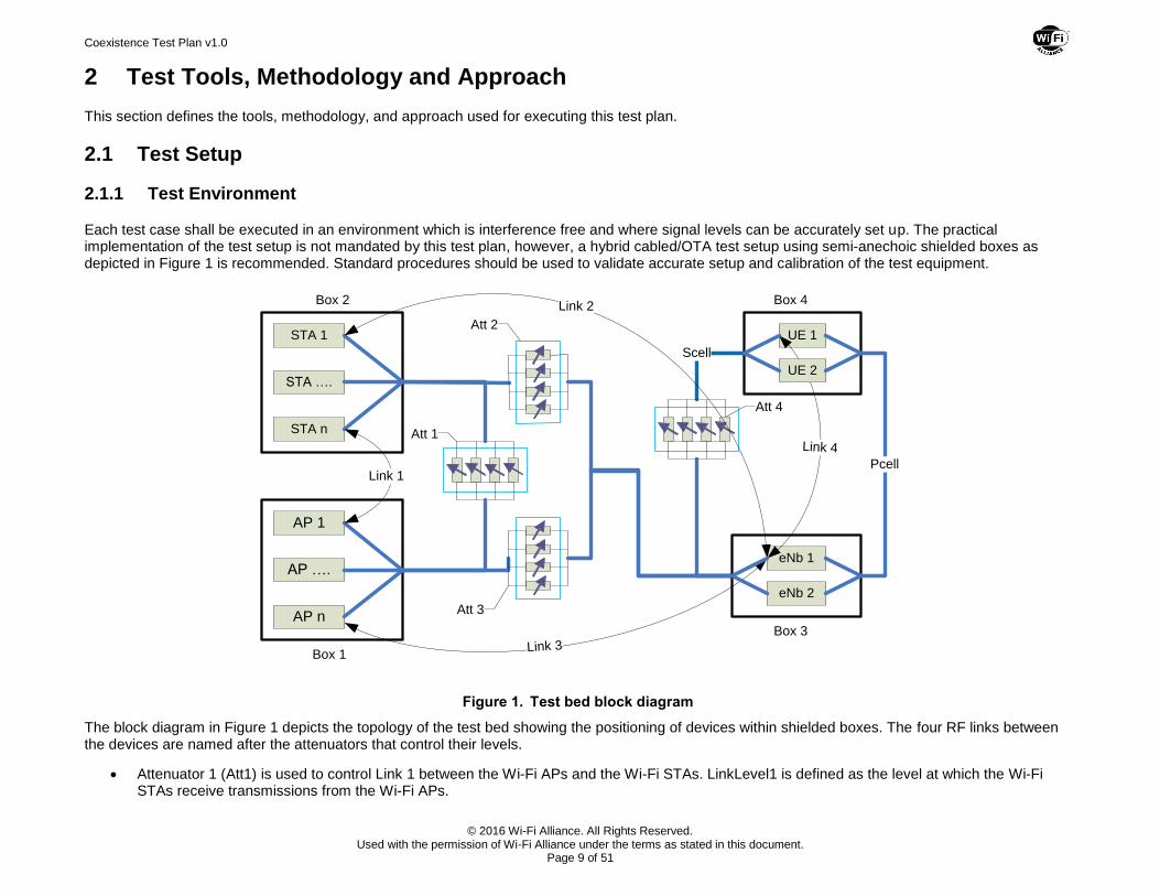
Each test case shall be executed in an environment which is interference free and where signal levels can be accurately set up. The practical implementation of the test setup is not mandated by this test plan, however, a hybrid cabled/OTA test setup using semi-anechoic shielded boxes as depicted in Figure 1 is recommended. Standard procedures should be used to validate accurate setup and calibration of the test equipment.
AP 1
Att 1
Att 3
Att 2STA 1
Scell
Att 4
Box 1
Box 2
Box 3
Box 4
eNb 1
UE 1
AP n
AP ….
Link 3
STA ….
STA n
Pcell
Link 2
Link 1
Link 4
UE 2
eNb 2
Figure 1. Test bed block diagram
The block diagram in Figure 1 depicts the topology of the test bed showing the positioning of devices within shielded boxes. The four RF links between the devices are named after the attenuators that control their levels.
Attenuator 1 (Att1) is used to control Link 1 between the Wi-Fi APs and the Wi-Fi STAs. LinkLevel1 is defined as the level at which the Wi-Fi STAs receive transmissions from the Wi-Fi APs.
Coexistence Test Plan v1.0
© 2016 Wi-Fi Alliance. All Rights Reserved. Used with the permission of Wi-Fi Alliance under the terms as stated in this document.
Page 10 of 51
Attenuator 2 (Att2) is used to control Link 2 between the Wi-Fi STAs and the eNBs. LinkLevel2 is defined as the level at which the eNBs receives transmissions from the Wi-Fi STAs.
Attenuator 3 (Att3) is used to control Link 3 between the Wi-Fi APs and the eNBs. LinkLevel3 is defined as the level at which the eNBs receives transmissions from the Wi-Fi APs.
Attenuator 4 (Att4) is used to control Link 4 between the UEs and the eNBs. LinkLevel4 is defined as the level at which the UEs receive transmissions from the eNBs.
In this test plan, the tests are performed at the three different signal levels listed below.
Test Level 1 (-50 dBm)
Test Level 2 (-67 dBm)
Test Level 3 (-82 dBm)
LinkLevel1, LinkLevel2, LinkLevel3, and LinkLevel4, defined above, are set to the required test level indicated by each test.
The Wi-Fi multivendor benchmark data used to establish the pass/fail criteria shall be obtained at the test signal levels defined above and using similar configurations of equipment. When performing the Wi-Fi benchmark measurements, allowances should be made to ensure symmetrical configurations so that all Wi-Fi nodes are audible to each other.
2.2 Test Equipment
2.2.1 Traffic Generator Performance Analysis Tool
A wireless performance test tool shall be used to generate test data and analyze performance of the devices in the networks. The wireless performance tool also captures RAT and system information from the device and reports standard Wi-Fi information such as channel, BSSID, RSSI and PHY Rate from the client perspective.
Some of the test cases in this test plan collect the most relevant key performance indicators (KPIs), such as:
Throughput
Latency (one-way delay)
Jitter (latency variation)
This test plan does not mandate a specific traffic generator and wireless performance test tool for carrying out testing. The set of minimum requirements the performance test tool shall support are listed below.
Multiple endpoints running simultaneously to address testing requirement
Collection of key performance indicators (KPIs) such as throughput, latency and jitter
Collection of RAT and system information and standard Wi-Fi information such as channel, BSSID, RSSI and PHY rate
Ability to control the type of traffic as per the test case requirement
Wi-Fi Alliance evaluated a performance test tool provided by AT4 wireless. The tool comprises two main parts: a test controller running on a server machine under Windows 2012, and client agents running on each of the clients in the test. Additional information about the tool may be found in [2]
Coexistence Test Plan v1.0
© 2016 Wi-Fi Alliance. All Rights Reserved. Used with the permission of Wi-Fi Alliance under the terms as stated in this document.
Page 11 of 51
2.2.2 Definition of Percentage Load
Several test cases in the test plan refer to desired load conditions between the AP and STA in terms of percentage. These load conditions are achieved by first calibrating the wireless link to determine the maximum link capacity, and then by restricting the traffic generator to achieve the desired load using the following procedure.
1. Configure a single Wi-Fi AP-STA at the desired link level with no other devices active.
2. Run a throughput test with traffic that exceeds the capacity of the PHY. For example, if the maximum PHY rate is 173.3 Mbps, then set a traffic generator to 125% of this number, or 217 Mbps. This ensures that the device is always operating with full buffer traffic.
3. Record the received throughput. The traffic received under these conditions represents the full buffer traffic load, which is the 100% load condition for that particular Link Level.
4. Restrict the traffic generator to the desired percentage load:
Traffic generator load = (Percentage load desired) * (Throughput measured in step 3)
2.2.3 Access Point and Station Devices
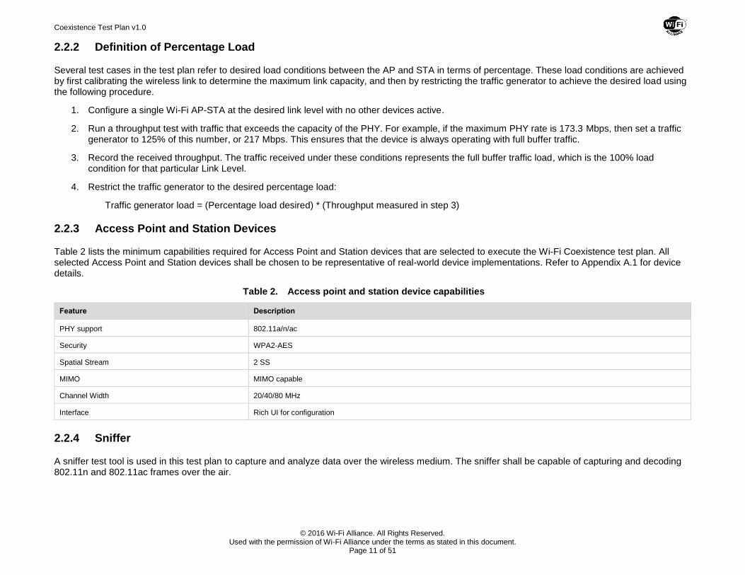
Table 2 lists the minimum capabilities required for Access Point and Station devices that are selected to execute the Wi-Fi Coexistence test plan. All selected Access Point and Station devices shall be chosen to be representative of real-world device implementations. Refer to Appendix A.1 for device details.
Table 2. Access point and station device capabilities
Feature Description
PHY support 802.11a/n/ac
Security WPA2-AES
Spatial Stream 2 SS
MIMO MIMO capable
Channel Width 20/40/80 MHz
Interface Rich UI for configuration
2.2.4 Sniffer
A sniffer test tool is used in this test plan to capture and analyze data over the wireless medium. The sniffer shall be capable of capturing and decoding 802.11n and 802.11ac frames over the air.
Coexistence Test Plan v1.0
© 2016 Wi-Fi Alliance. All Rights Reserved. Used with the permission of Wi-Fi Alliance under the terms as stated in this document.
Page 12 of 51
3 LTE-U and Wi-Fi Coexistence Test Requirements
3.1 Applicability of Tests
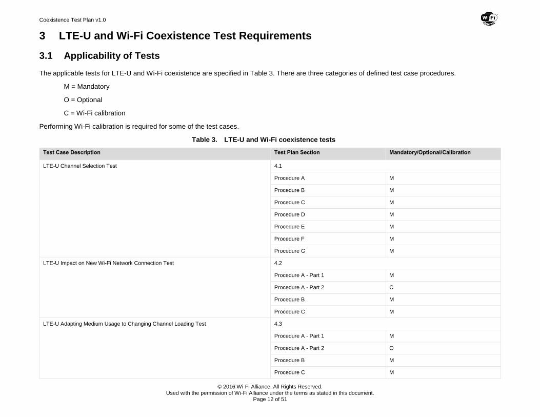
The applicable tests for LTE-U and Wi-Fi coexistence are specified in Table 3. There are three categories of defined test case procedures.
M = Mandatory
O = Optional
C = Wi-Fi calibration
Performing Wi-Fi calibration is required for some of the test cases.
Table 3. LTE-U and Wi-Fi coexistence tests
Test Case Description Test Plan Section Mandatory/Optional/Calibration
LTE-U Channel Selection Test 4.1
Procedure A M
Procedure B M
Procedure C M
Procedure D M
Procedure E M
Procedure F M
Procedure G M
LTE-U Impact on New Wi-Fi Network Connection Test 4.2
Procedure A - Part 1 M
Procedure A - Part 2 C
Procedure B M
Procedure C M
LTE-U Adapting Medium Usage to Changing Channel Loading Test 4.3
Procedure A - Part 1 M
Procedure A - Part 2 O
Procedure B M
Procedure C M
Coexistence Test Plan v1.0
© 2016 Wi-Fi Alliance. All Rights Reserved. Used with the permission of Wi-Fi Alliance under the terms as stated in this document.
Page 13 of 51
Test Case Description Test Plan Section Mandatory/Optional/Calibration
Procedure D M
Procedure E M
Procedure F O
LTE-U Impact on Latency Sensitive Wi-Fi Traffic Test 4.4
Procedure A C
Procedure B M
Procedure C M
LTE-U Impact on Wi-Fi Throughput Performance Test 4.5
Procedure A C
Procedure B C
Procedure C M
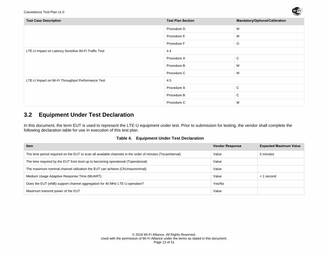
3.2 Equipment Under Test Declaration
In this document, the term EUT is used to represent the LTE-U equipment under test. Prior to submission for testing, the vendor shall complete the following declaration table for use in execution of this test plan.
Table 4. Equipment Under Test Declaration
Item Vendor Response Expected Maximum Value
The time period required on the EUT to scan all available channels in the order of minutes (Tscaninterval) Value 5 minutes
The time required by the EUT from boot up to becoming operational (Toperational) Value
The maximum nominal channel utilization the EUT can achieve (ChUmaxnominal) Value
Medium Usage Adaptive Response Time (MUART) Value < 1 second
Does the EUT (eNB) support channel aggregation for 40 MHz LTE-U operation? Yes/No
Maximum transmit power of the EUT Value
Coexistence Test Plan v1.0
© 2016 Wi-Fi Alliance. All Rights Reserved. Used with the permission of Wi-Fi Alliance under the terms as stated in this document.
Page 14 of 51
3.3 Wi-Fi Device Configuration Requirements
3.3.1 Access Point Configuration
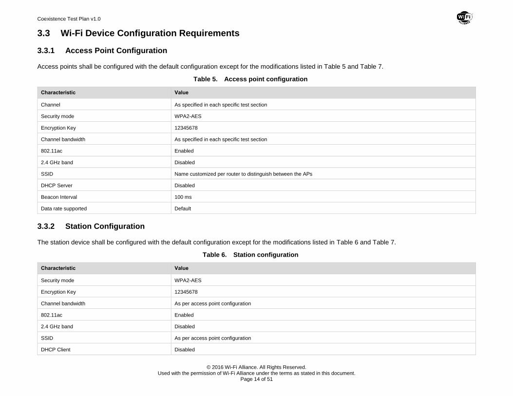
Access points shall be configured with the default configuration except for the modifications listed in Table 5 and Table 7.
Table 5. Access point configuration
Characteristic Value
Channel As specified in each specific test section
Security mode WPA2-AES
Encryption Key 12345678
Channel bandwidth As specified in each specific test section
802.11ac Enabled
2.4 GHz band Disabled
SSID Name customized per router to distinguish between the APs
DHCP Server Disabled
Beacon Interval 100 ms
Data rate supported Default
3.3.2 Station Configuration
The station device shall be configured with the default configuration except for the modifications listed in Table 6 and Table 7.
Table 6. Station configuration
Characteristic Value
Security mode WPA2-AES
Encryption Key 12345678
Channel bandwidth As per access point configuration
802.11ac Enabled
2.4 GHz band Disabled
SSID As per access point configuration
DHCP Client Disabled
Coexistence Test Plan v1.0
© 2016 Wi-Fi Alliance. All Rights Reserved. Used with the permission of Wi-Fi Alliance under the terms as stated in this document.
Page 15 of 51
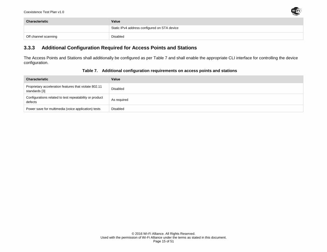
Characteristic Value
Static IPv4 address configured on STA device
Off channel scanning Disabled
3.3.3 Additional Configuration Required for Access Points and Stations
The Access Points and Stations shall additionally be configured as per Table 7 and shall enable the appropriate CLI interface for controlling the device configuration.
Table 7. Additional configuration requirements on access points and stations
Characteristic Value
Proprietary acceleration features that violate 802.11
standards [3] Disabled
Configurations related to test repeatability or product
defects As required
Power save for multimedia (voice application) tests Disabled
Coexistence Test Plan v1.0
© 2016 Wi-Fi Alliance. All Rights Reserved. Used with the permission of Wi-Fi Alliance under the terms as stated in this document.
Page 16 of 51
4 LTE-U and Wi-Fi Coexistence Tests
The test cases in this section validate the coexistence of LTE-U equipment with Wi-Fi equipment when the LTE and Wi-Fi equipment can hear each other at the signal levels defined in section 2.1.1. Each test case includes multiple procedures that are labeled alphabetically. For all test cases in this section, the term EUT is used to represent the LTE-U equipment under test.
The EUT shall be configured once prior to the test case execution and shall not be altered between the test case procedures unless otherwise stated in the test procedure. Manual or electronic intervention or adjustment of the LTE-U equipment under test is not permitted between procedures or within a procedure of a given test case unless explicitly stated otherwise. This will ensure that the dynamic qualities of the LTE coexistence features are properly tested.
4.1 LTE-U Channel Selection Test
Purpose and Description
This test verifies that the EUT can identify and report:
1. A vacant unlicensed channel when all but one of the unlicensed channels have active Wi-Fi nodes. The EUT shall sense the spectrum to identify the vacant channel and begin operating in the vacant channel.
2. The least utilized unlicensed channel when all unlicensed channels have active Wi-Fi nodes, intra-operator and inter-operator LTE-U nodes. The EUT should sense the spectrum to identify that there are no vacant channels available for its use, assess the load on each channel, and determine the least utilized channel.
Unlicensed channels in the U-NII-1 (5150 MHz -5250 MHz) and the U-NII-3 (5725 MHz -5825 MHz) bands are used for this test.
References
None.
Test Environment
1 EUT
1 LTE-U eNBs operating as test bed device
2 LTE-U UEs operating as test bed devices
4 Wi-Fi CERTIFIED access points capable of operating in 11a only and 11n mode
4 Wi-Fi CERTIFIED ac stations
1 wireless sniffer
1 Wi-Fi data traffic generator
LinkLevel1 = LinkLevel2 = LinkLevel3 = LinkLevel4 = Test Level being used
Wi-Fi Benchmark
No Wi-Fi benchmark data are required for this test.
Coexistence Test Plan v1.0
© 2016 Wi-Fi Alliance. All Rights Reserved. Used with the permission of Wi-Fi Alliance under the terms as stated in this document.
Page 17 of 51
Test Configuration
Refer to Table 5, Table 6, and Table 7 for access point and station device configuration.
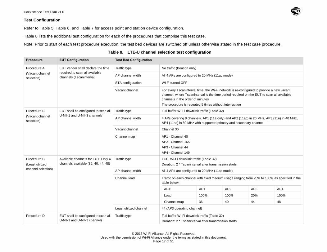
Table 8 lists the additional test configuration for each of the procedures that comprise this test case.
Note: Prior to start of each test procedure execution, the test bed devices are switched off unless otherwise stated in the test case procedure.
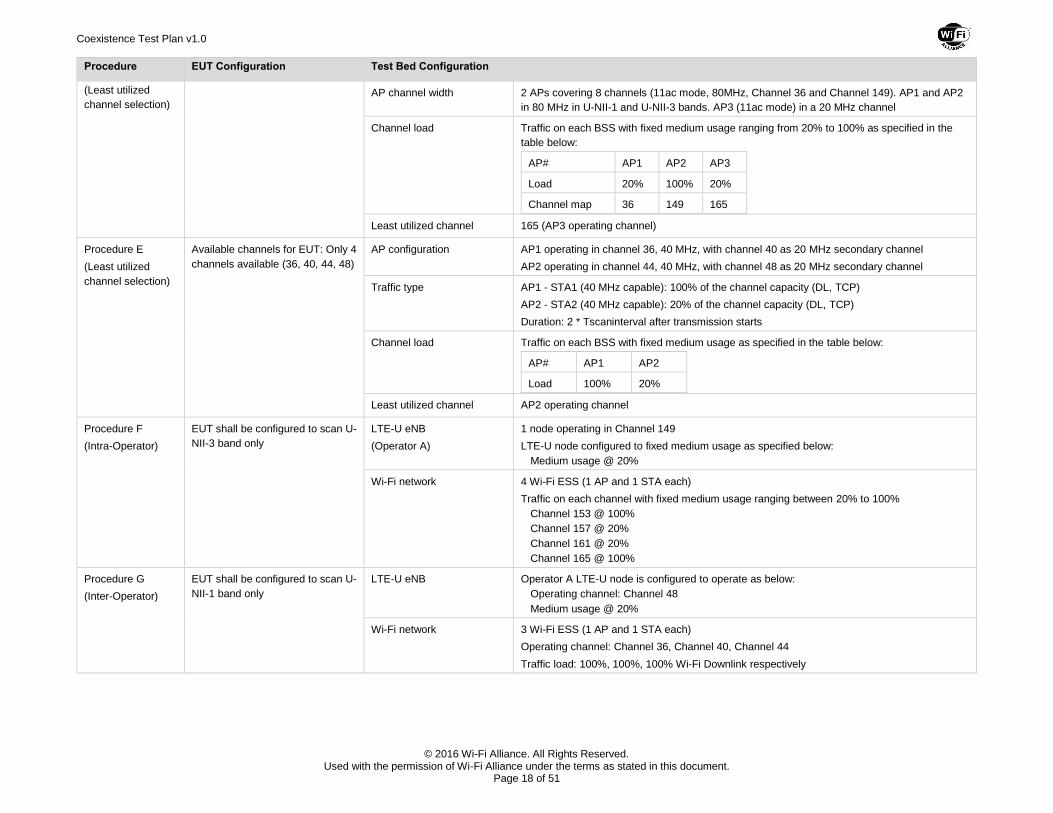
Table 8. LTE-U channel selection test configuration
Procedure EUT Configuration Test Bed Configuration
Procedure A
(Vacant channel
selection)
EUT vendor shall declare the time
required to scan all available
channels (Tscaninterval)
Traffic type No traffic (Beacon only)
AP channel width All 4 APs are configured to 20 MHz (11ac mode)
STA configuration Wi-Fi turned OFF
Vacant channel For every Tscaninterval time, the Wi-Fi network is re-configured to provide a new vacant
channel, where Tscaninterval is the time period required on the EUT to scan all available
channels in the order of minutes
The procedure is repeated 5 times without interruption
Procedure B
(Vacant channel
selection)
EUT shall be configured to scan all
U-NII-1 and U-NII-3 channels
Traffic type Full buffer Wi-Fi downlink traffic (Table 32)
AP channel width 4 APs covering 8 channels. AP1 (11a only) and AP2 (11ac) in 20 MHz, AP3 (11n) in 40 MHz,
AP4 (11ac) in 80 MHz with supported primary and secondary channel
Vacant channel Channel 36
Channel map AP1 - Channel 40
AP2 - Channel 165
AP3 - Channel 44
AP4 - Channel 149
Procedure C
(Least utilized
channel selection)
Available channels for EUT: Only 4
channels available (36, 40, 44, 48)
Traffic type TCP, Wi-Fi downlink traffic (Table 32)
Duration: 2 * Tscaninterval after transmission starts
AP channel width All 4 APs are configured to 20 MHz (11ac mode)
Channel load Traffic on each channel with fixed medium usage ranging from 20% to 100% as specified in the
table below:
AP# AP1 AP2 AP3 AP4
Load 100% 100% 20% 100%
Channel map 36 40 44 48
Least utilized channel 44 (AP3 operating channel)
Procedure D EUT shall be configured to scan all
U-NII-1 and U-NII-3 channels
Traffic type Full buffer Wi-Fi downlink traffic (Table 32)
Duration: 2 * Tscaninterval after transmission starts
Coexistence Test Plan v1.0
© 2016 Wi-Fi Alliance. All Rights Reserved. Used with the permission of Wi-Fi Alliance under the terms as stated in this document.
Page 18 of 51
Procedure EUT Configuration Test Bed Configuration
(Least utilized
channel selection) AP channel width 2 APs covering 8 channels (11ac mode, 80MHz, Channel 36 and Channel 149). AP1 and AP2
in 80 MHz in U-NII-1 and U-NII-3 bands. AP3 (11ac mode) in a 20 MHz channel
Channel load Traffic on each BSS with fixed medium usage ranging from 20% to 100% as specified in the
table below:
AP# AP1 AP2 AP3
Load 20% 100% 20%
Channel map 36 149 165
Least utilized channel 165 (AP3 operating channel)
Procedure E
(Least utilized
channel selection)
Available channels for EUT: Only 4
channels available (36, 40, 44, 48)
AP configuration AP1 operating in channel 36, 40 MHz, with channel 40 as 20 MHz secondary channel
AP2 operating in channel 44, 40 MHz, with channel 48 as 20 MHz secondary channel
Traffic type AP1 - STA1 (40 MHz capable): 100% of the channel capacity (DL, TCP)
AP2 - STA2 (40 MHz capable): 20% of the channel capacity (DL, TCP)
Duration: 2 * Tscaninterval after transmission starts
Channel load Traffic on each BSS with fixed medium usage as specified in the table below:
AP# AP1 AP2
Load 100% 20%
Least utilized channel AP2 operating channel
Procedure F
(Intra-Operator)
EUT shall be configured to scan U-
NII-3 band only
LTE-U eNB
(Operator A)
1 node operating in Channel 149
LTE-U node configured to fixed medium usage as specified below:
Medium usage @ 20%
Wi-Fi network 4 Wi-Fi ESS (1 AP and 1 STA each)
Traffic on each channel with fixed medium usage ranging between 20% to 100%
Channel 153 @ 100%
Channel 157 @ 20%
Channel 161 @ 20%
Channel 165 @ 100%
Procedure G
(Inter-Operator)
EUT shall be configured to scan U-
NII-1 band only
LTE-U eNB Operator A LTE-U node is configured to operate as below:
Operating channel: Channel 48
Medium usage @ 20%
Wi-Fi network 3 Wi-Fi ESS (1 AP and 1 STA each)
Operating channel: Channel 36, Channel 40, Channel 44
Traffic load: 100%, 100%, 100% Wi-Fi Downlink respectively
Coexistence Test Plan v1.0
© 2016 Wi-Fi Alliance. All Rights Reserved. Used with the permission of Wi-Fi Alliance under the terms as stated in this document.
Page 19 of 51
Test Procedure
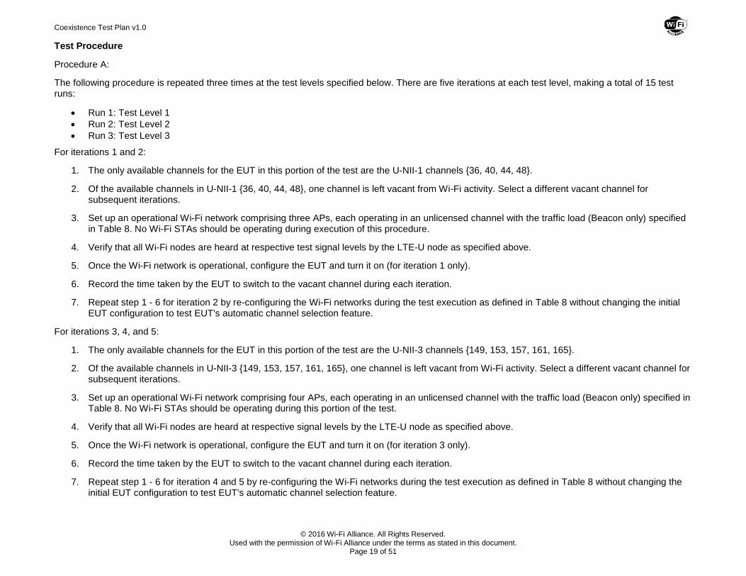
Procedure A:
The following procedure is repeated three times at the test levels specified below. There are five iterations at each test level, making a total of 15 test runs:
Run 1: Test Level 1
Run 2: Test Level 2
Run 3: Test Level 3
For iterations 1 and 2:
1. The only available channels for the EUT in this portion of the test are the U-NII-1 channels {36, 40, 44, 48}.
2. Of the available channels in U-NII-1 {36, 40, 44, 48}, one channel is left vacant from Wi-Fi activity. Select a different vacant channel for subsequent iterations.
3. Set up an operational Wi-Fi network comprising three APs, each operating in an unlicensed channel with the traffic load (Beacon only) specified in Table 8. No Wi-Fi STAs should be operating during execution of this procedure.
4. Verify that all Wi-Fi nodes are heard at respective test signal levels by the LTE-U node as specified above.
5. Once the Wi-Fi network is operational, configure the EUT and turn it on (for iteration 1 only).
6. Record the time taken by the EUT to switch to the vacant channel during each iteration.
7. Repeat step 1 - 6 for iteration 2 by re-configuring the Wi-Fi networks during the test execution as defined in Table 8 without changing the initial EUT configuration to test EUT's automatic channel selection feature.
For iterations 3, 4, and 5:
1. The only available channels for the EUT in this portion of the test are the U-NII-3 channels {149, 153, 157, 161, 165}.
2. Of the available channels in U-NII-3 {149, 153, 157, 161, 165}, one channel is left vacant from Wi-Fi activity. Select a different vacant channel for subsequent iterations.
3. Set up an operational Wi-Fi network comprising four APs, each operating in an unlicensed channel with the traffic load (Beacon only) specified in Table 8. No Wi-Fi STAs should be operating during this portion of the test.
4. Verify that all Wi-Fi nodes are heard at respective signal levels by the LTE-U node as specified above.
5. Once the Wi-Fi network is operational, configure the EUT and turn it on (for iteration 3 only).
6. Record the time taken by the EUT to switch to the vacant channel during each iteration.
7. Repeat step 1 - 6 for iteration 4 and 5 by re-configuring the Wi-Fi networks during the test execution as defined in Table 8 without changing the initial EUT configuration to test EUT's automatic channel selection feature.
Coexistence Test Plan v1.0
© 2016 Wi-Fi Alliance. All Rights Reserved. Used with the permission of Wi-Fi Alliance under the terms as stated in this document.
Page 20 of 51
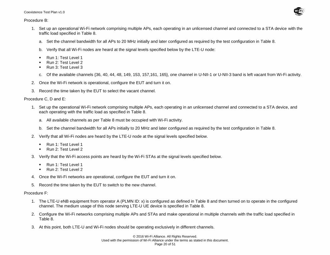
Procedure B:
1. Set up an operational Wi-Fi network comprising multiple APs, each operating in an unlicensed channel and connected to a STA device with the traffic load specified in Table 8.
a. Set the channel bandwidth for all APs to 20 MHz initially and later configured as required by the test configuration in Table 8.
b. Verify that all Wi-Fi nodes are heard at the signal levels specified below by the LTE-U node:
Run 1: Test Level 1 Run 2: Test Level 2 Run 3: Test Level 3
c. Of the available channels {36, 40, 44, 48, 149, 153, 157,161, 165}, one channel in U-NII-1 or U-NII-3 band is left vacant from Wi-Fi activity.
2. Once the Wi-Fi network is operational, configure the EUT and turn it on.
3. Record the time taken by the EUT to select the vacant channel.
Procedure C, D and E:
1. Set up the operational Wi-Fi network comprising multiple APs, each operating in an unlicensed channel and connected to a STA device, and each operating with the traffic load as specified in Table 8.
a. All available channels as per Table 8 must be occupied with Wi-Fi activity.
b. Set the channel bandwidth for all APs initially to 20 MHz and later configured as required by the test configuration in Table 8.
2. Verify that all Wi-Fi nodes are heard by the LTE-U node at the signal levels specified below.
Run 1: Test Level 1 Run 2: Test Level 2
3. Verify that the Wi-Fi access points are heard by the Wi-Fi STAs at the signal levels specified below.
Run 1: Test Level 1 Run 2: Test Level 2
4. Once the Wi-Fi networks are operational, configure the EUT and turn it on.
5. Record the time taken by the EUT to switch to the new channel.
Procedure F:
1. The LTE-U eNB equipment from operator A (PLMN ID: x) is configured as defined in Table 8 and then turned on to operate in the configured channel. The medium usage of this node serving LTE-U UE device is specified in Table 8.
2. Configure the Wi-Fi networks comprising multiple APs and STAs and make operational in multiple channels with the traffic load specified in Table 8.
3. At this point, both LTE-U and Wi-Fi nodes should be operating exclusively in different channels.
Coexistence Test Plan v1.0
© 2016 Wi-Fi Alliance. All Rights Reserved. Used with the permission of Wi-Fi Alliance under the terms as stated in this document.
Page 21 of 51
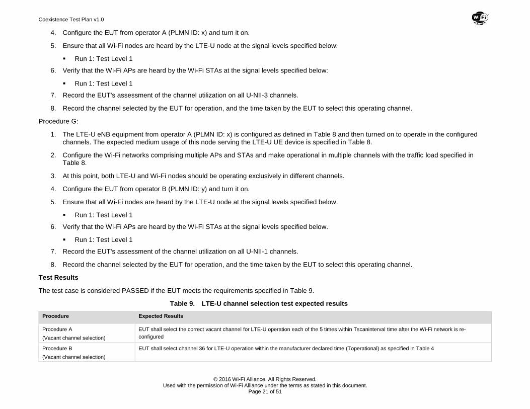
4. Configure the EUT from operator A (PLMN ID: x) and turn it on.
5. Ensure that all Wi-Fi nodes are heard by the LTE-U node at the signal levels specified below:
Run 1: Test Level 1
6. Verify that the Wi-Fi APs are heard by the Wi-Fi STAs at the signal levels specified below:
Run 1: Test Level 1
7. Record the EUT's assessment of the channel utilization on all U-NII-3 channels.
8. Record the channel selected by the EUT for operation, and the time taken by the EUT to select this operating channel.
Procedure G:
1. The LTE-U eNB equipment from operator A (PLMN ID: x) is configured as defined in Table 8 and then turned on to operate in the configured channels. The expected medium usage of this node serving the LTE-U UE device is specified in Table 8.
2. Configure the Wi-Fi networks comprising multiple APs and STAs and make operational in multiple channels with the traffic load specified in Table 8.
3. At this point, both LTE-U and Wi-Fi nodes should be operating exclusively in different channels.
4. Configure the EUT from operator B (PLMN ID: y) and turn it on.
5. Ensure that all Wi-Fi nodes are heard by the LTE-U node at the signal levels specified below.
Run 1: Test Level 1
6. Verify that the Wi-Fi APs are heard by the Wi-Fi STAs at the signal levels specified below.
Run 1: Test Level 1
7. Record the EUT's assessment of the channel utilization on all U-NII-1 channels.
8. Record the channel selected by the EUT for operation, and the time taken by the EUT to select this operating channel.
Test Results
The test case is considered PASSED if the EUT meets the requirements specified in Table 9.
Table 9. LTE-U channel selection test expected results
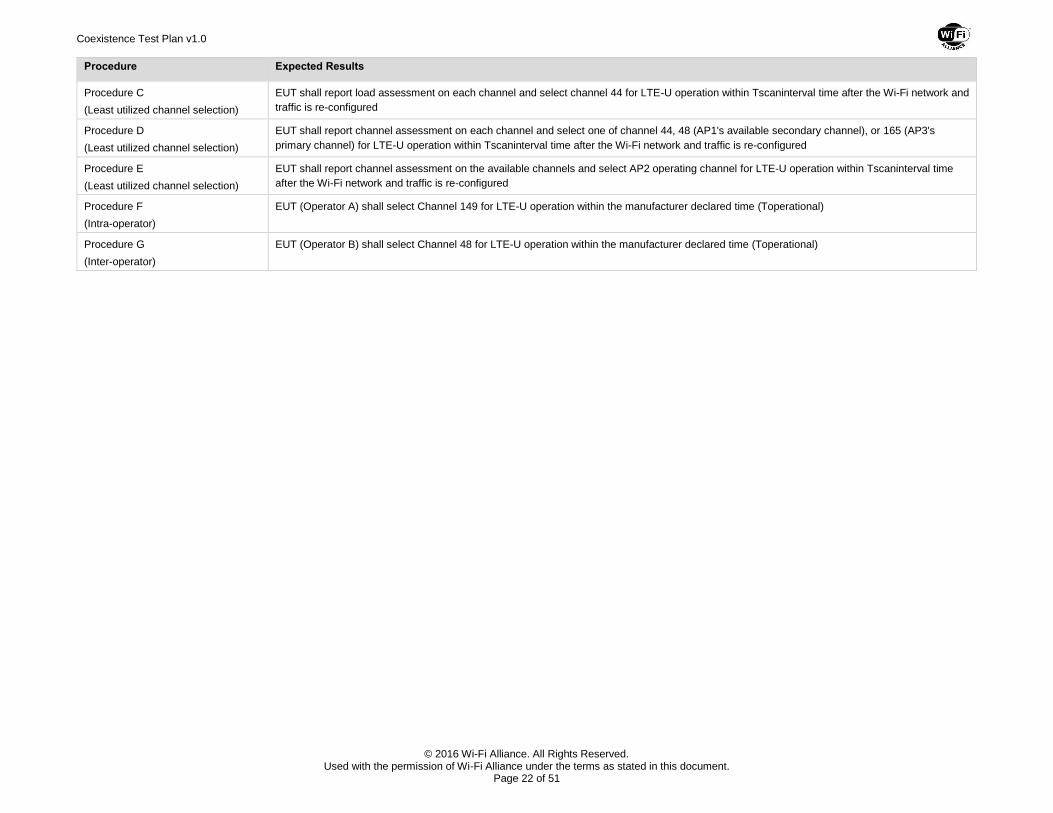
Procedure Expected Results
Procedure A
(Vacant channel selection)
EUT shall select the correct vacant channel for LTE-U operation each of the 5 times within Tscaninterval time after the Wi-Fi network is re-
configured
Procedure B
(Vacant channel selection)
EUT shall select channel 36 for LTE-U operation within the manufacturer declared time (Toperational) as specified in Table 4
Coexistence Test Plan v1.0
© 2016 Wi-Fi Alliance. All Rights Reserved. Used with the permission of Wi-Fi Alliance under the terms as stated in this document.
Page 22 of 51
Procedure Expected Results
Procedure C
(Least utilized channel selection)
EUT shall report load assessment on each channel and select channel 44 for LTE-U operation within Tscaninterval time after the Wi-Fi network and
traffic is re-configured
Procedure D
(Least utilized channel selection)
EUT shall report channel assessment on each channel and select one of channel 44, 48 (AP1's available secondary channel), or 165 (AP3's
primary channel) for LTE-U operation within Tscaninterval time after the Wi-Fi network and traffic is re-configured
Procedure E
(Least utilized channel selection)
EUT shall report channel assessment on the available channels and select AP2 operating channel for LTE-U operation within Tscaninterval time
after the Wi-Fi network and traffic is re-configured
Procedure F
(Intra-operator)
EUT (Operator A) shall select Channel 149 for LTE-U operation within the manufacturer declared time (Toperational)
Procedure G
(Inter-operator)
EUT (Operator B) shall select Channel 48 for LTE-U operation within the manufacturer declared time (Toperational)
Coexistence Test Plan v1.0
© 2016 Wi-Fi Alliance. All Rights Reserved. Used with the permission of Wi-Fi Alliance under the terms as stated in this document.
Page 23 of 51
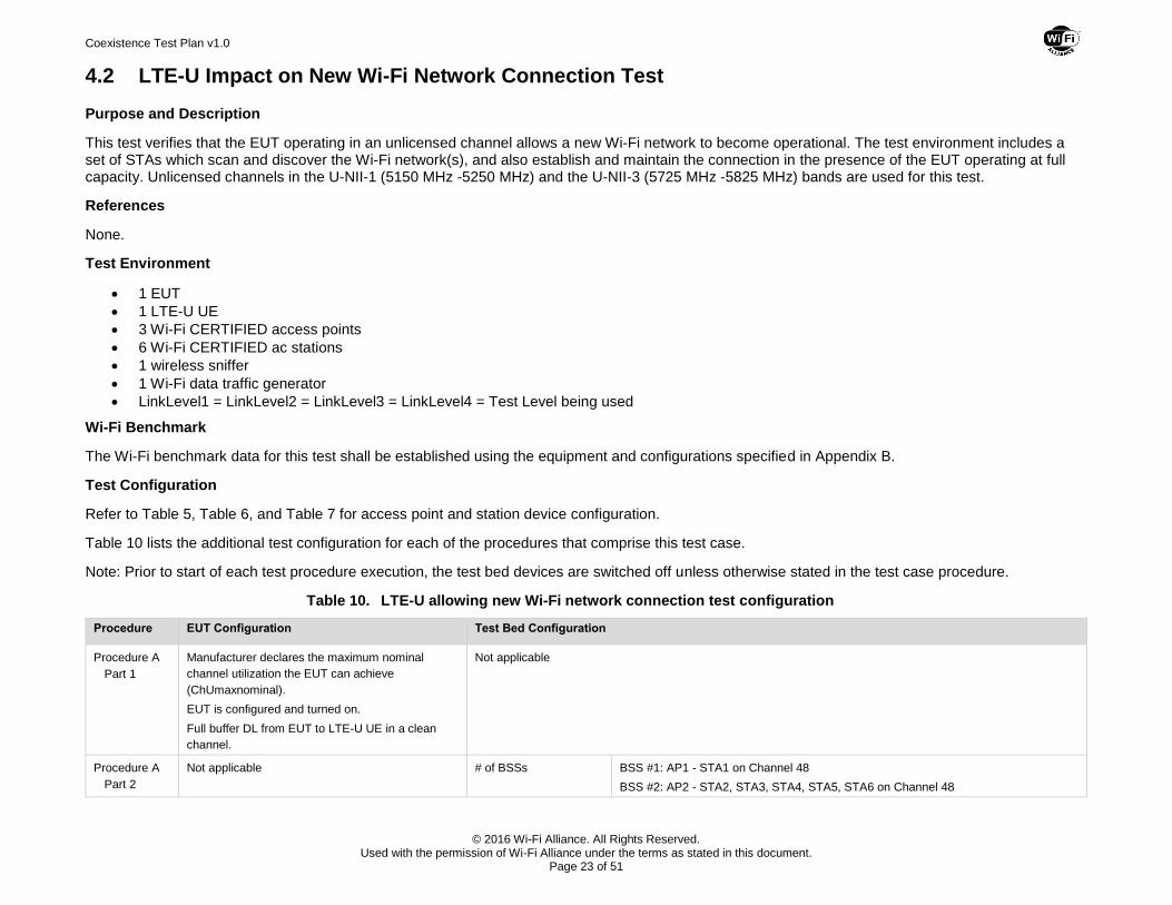
4.2 LTE-U Impact on New Wi-Fi Network Connection Test
Purpose and Description
This test verifies that the EUT operating in an unlicensed channel allows a new Wi-Fi network to become operational. The test environment includes a set of STAs which scan and discover the Wi-Fi network(s), and also establish and maintain the connection in the presence of the EUT operating at full capacity. Unlicensed channels in the U-NII-1 (5150 MHz -5250 MHz) and the U-NII-3 (5725 MHz -5825 MHz) bands are used for this test.
References
None.
Test Environment
1 EUT
1 LTE-U UE
3 Wi-Fi CERTIFIED access points
6 Wi-Fi CERTIFIED ac stations
1 wireless sniffer
1 Wi-Fi data traffic generator
LinkLevel1 = LinkLevel2 = LinkLevel3 = LinkLevel4 = Test Level being used
Wi-Fi Benchmark
The Wi-Fi benchmark data for this test shall be established using the equipment and configurations specified in Appendix B.
Test Configuration
Refer to Table 5, Table 6, and Table 7 for access point and station device configuration.
Table 10 lists the additional test configuration for each of the procedures that comprise this test case.
Note: Prior to start of each test procedure execution, the test bed devices are switched off unless otherwise stated in the test case procedure.
Table 10. LTE-U allowing new Wi-Fi network connection test configuration
Procedure EUT Configuration Test Bed Configuration
Procedure A
Part 1
Manufacturer declares the maximum nominal
channel utilization the EUT can achieve
(ChUmaxnominal).
EUT is configured and turned on.
Full buffer DL from EUT to LTE-U UE in a clean
channel.
Not applicable
Procedure A
Part 2
Not applicable # of BSSs BSS #1: AP1 - STA1 on Channel 48
BSS #2: AP2 - STA2, STA3, STA4, STA5, STA6 on Channel 48
Coexistence Test Plan v1.0
© 2016 Wi-Fi Alliance. All Rights Reserved. Used with the permission of Wi-Fi Alliance under the terms as stated in this document.
Page 24 of 51
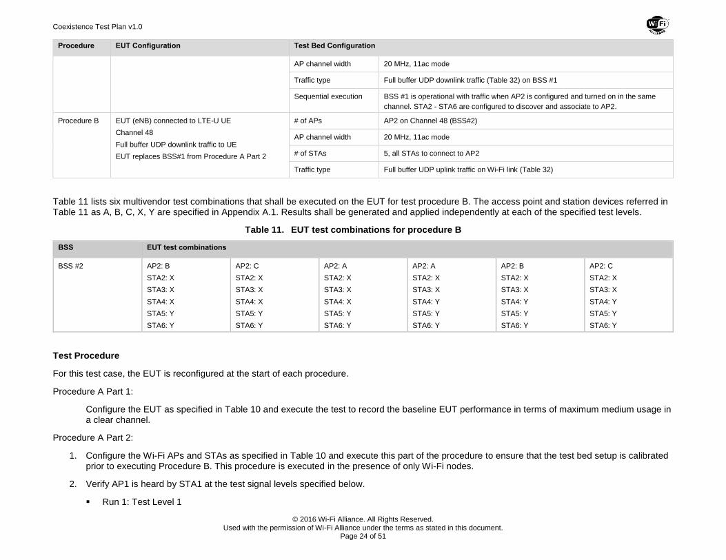
Procedure EUT Configuration Test Bed Configuration
AP channel width 20 MHz, 11ac mode
Traffic type Full buffer UDP downlink traffic (Table 32) on BSS #1
Sequential execution BSS #1 is operational with traffic when AP2 is configured and turned on in the same
channel. STA2 - STA6 are configured to discover and associate to AP2.
Procedure B EUT (eNB) connected to LTE-U UE
Channel 48
Full buffer UDP downlink traffic to UE
EUT replaces BSS#1 from Procedure A Part 2
# of APs AP2 on Channel 48 (BSS#2)
AP channel width 20 MHz, 11ac mode
# of STAs 5, all STAs to connect to AP2
Traffic type Full buffer UDP uplink traffic on Wi-Fi link (Table 32)
Table 11 lists six multivendor test combinations that shall be executed on the EUT for test procedure B. The access point and station devices referred in Table 11 as A, B, C, X, Y are specified in Appendix A.1. Results shall be generated and applied independently at each of the specified test levels.
Table 11. EUT test combinations for procedure B
BSS EUT test combinations
BSS #2 AP2: B
STA2: X
STA3: X
STA4: X
STA5: Y
STA6: Y
AP2: C
STA2: X
STA3: X
STA4: X
STA5: Y
STA6: Y
AP2: A
STA2: X
STA3: X
STA4: X
STA5: Y
STA6: Y
AP2: A
STA2: X
STA3: X
STA4: Y
STA5: Y
STA6: Y
AP2: B
STA2: X
STA3: X
STA4: Y
STA5: Y
STA6: Y
AP2: C
STA2: X
STA3: X
STA4: Y
STA5: Y
STA6: Y
Test Procedure
For this test case, the EUT is reconfigured at the start of each procedure.
Procedure A Part 1:
Configure the EUT as specified in Table 10 and execute the test to record the baseline EUT performance in terms of maximum medium usage in a clear channel.
Procedure A Part 2:
1. Configure the Wi-Fi APs and STAs as specified in Table 10 and execute this part of the procedure to ensure that the test bed setup is calibrated prior to executing Procedure B. This procedure is executed in the presence of only Wi-Fi nodes.
2. Verify AP1 is heard by STA1 at the test signal levels specified below.
Run 1: Test Level 1
Coexistence Test Plan v1.0
© 2016 Wi-Fi Alliance. All Rights Reserved. Used with the permission of Wi-Fi Alliance under the terms as stated in this document.
Page 25 of 51
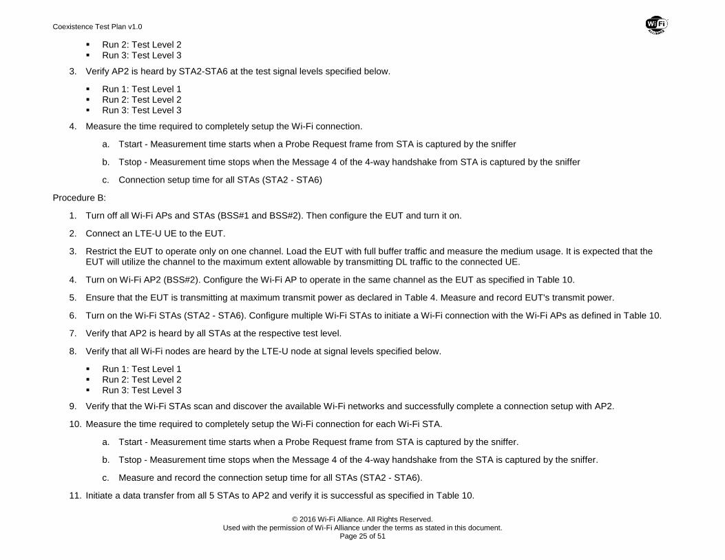
Run 2: Test Level 2 Run 3: Test Level 3
3. Verify AP2 is heard by STA2-STA6 at the test signal levels specified below.
Run 1: Test Level 1 Run 2: Test Level 2 Run 3: Test Level 3
4. Measure the time required to completely setup the Wi-Fi connection.
a. Tstart - Measurement time starts when a Probe Request frame from STA is captured by the sniffer
b. Tstop - Measurement time stops when the Message 4 of the 4-way handshake from STA is captured by the sniffer
c. Connection setup time for all STAs (STA2 - STA6)
Procedure B:
1. Turn off all Wi-Fi APs and STAs (BSS#1 and BSS#2). Then configure the EUT and turn it on.
2. Connect an LTE-U UE to the EUT.
3. Restrict the EUT to operate only on one channel. Load the EUT with full buffer traffic and measure the medium usage. It is expected that the EUT will utilize the channel to the maximum extent allowable by transmitting DL traffic to the connected UE.
4. Turn on Wi-Fi AP2 (BSS#2). Configure the Wi-Fi AP to operate in the same channel as the EUT as specified in Table 10.
5. Ensure that the EUT is transmitting at maximum transmit power as declared in Table 4. Measure and record EUT's transmit power.
6. Turn on the Wi-Fi STAs (STA2 - STA6). Configure multiple Wi-Fi STAs to initiate a Wi-Fi connection with the Wi-Fi APs as defined in Table 10.
7. Verify that AP2 is heard by all STAs at the respective test level.
8. Verify that all Wi-Fi nodes are heard by the LTE-U node at signal levels specified below.
Run 1: Test Level 1 Run 2: Test Level 2 Run 3: Test Level 3
9. Verify that the Wi-Fi STAs scan and discover the available Wi-Fi networks and successfully complete a connection setup with AP2.
10. Measure the time required to completely setup the Wi-Fi connection for each Wi-Fi STA.
a. Tstart - Measurement time starts when a Probe Request frame from STA is captured by the sniffer.
b. Tstop - Measurement time stops when the Message 4 of the 4-way handshake from the STA is captured by the sniffer.
c. Measure and record the connection setup time for all STAs (STA2 - STA6).
11. Initiate a data transfer from all 5 STAs to AP2 and verify it is successful as specified in Table 10.
Coexistence Test Plan v1.0
© 2016 Wi-Fi Alliance. All Rights Reserved. Used with the permission of Wi-Fi Alliance under the terms as stated in this document.
Page 26 of 51
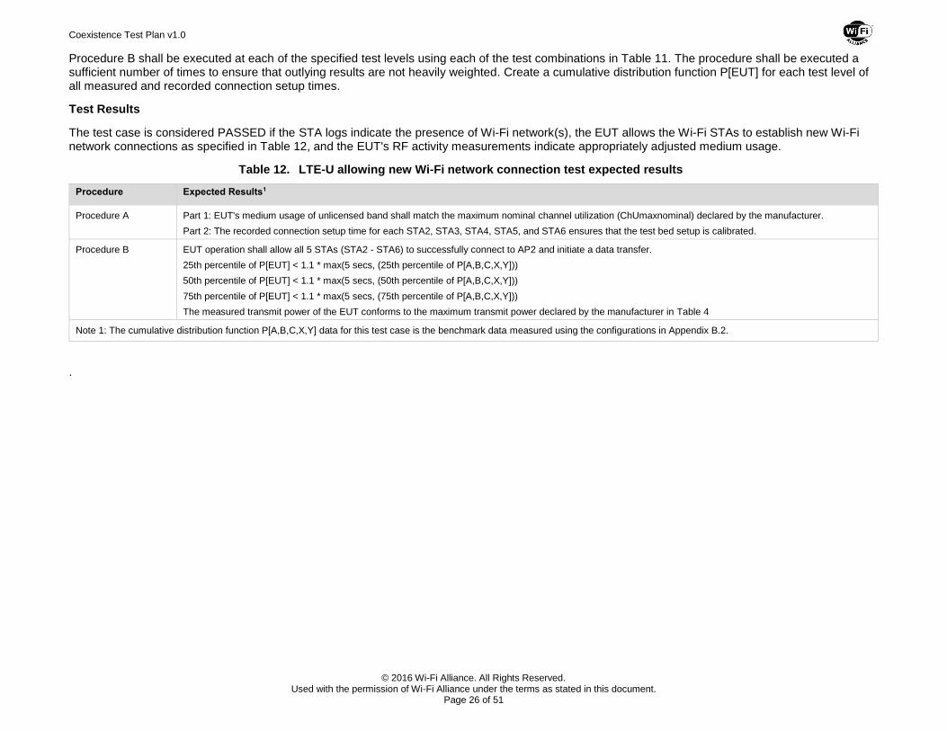
Procedure B shall be executed at each of the specified test levels using each of the test combinations in Table 11. The procedure shall be executed a sufficient number of times to ensure that outlying results are not heavily weighted. Create a cumulative distribution function P[EUT] for each test level of all measured and recorded connection setup times.
Test Results
The test case is considered PASSED if the STA logs indicate the presence of Wi-Fi network(s), the EUT allows the Wi-Fi STAs to establish new Wi-Fi network connections as specified in Table 12, and the EUT's RF activity measurements indicate appropriately adjusted medium usage.
Table 12. LTE-U allowing new Wi-Fi network connection test expected results
Procedure Expected Results1
Procedure A Part 1: EUT's medium usage of unlicensed band shall match the maximum nominal channel utilization (ChUmaxnominal) declared by the manufacturer.
Part 2: The recorded connection setup time for each STA2, STA3, STA4, STA5, and STA6 ensures that the test bed setup is calibrated.
Procedure B EUT operation shall allow all 5 STAs (STA2 - STA6) to successfully connect to AP2 and initiate a data transfer.
25th percentile of P[EUT] < 1.1 * max(5 secs, (25th percentile of P[A,B,C,X,Y]))
50th percentile of P[EUT] < 1.1 * max(5 secs, (50th percentile of P[A,B,C,X,Y]))
75th percentile of P[EUT] < 1.1 * max(5 secs, (75th percentile of P[A,B,C,X,Y]))
The measured transmit power of the EUT conforms to the maximum transmit power declared by the manufacturer in Table 4
Note 1: The cumulative distribution function P[A,B,C,X,Y] data for this test case is the benchmark data measured using the configurations in Appendix B.2.
.
Coexistence Test Plan v1.0
© 2016 Wi-Fi Alliance. All Rights Reserved. Used with the permission of Wi-Fi Alliance under the terms as stated in this document.
Page 27 of 51
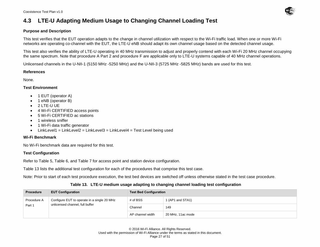
4.3 LTE-U Adapting Medium Usage to Changing Channel Loading Test
Purpose and Description
This test verifies that the EUT operation adapts to the change in channel utilization with respect to the Wi-Fi traffic load. When one or more Wi-Fi networks are operating co-channel with the EUT, the LTE-U eNB should adapt its own channel usage based on the detected channel usage.
This test also verifies the ability of LTE-U operating in 40 MHz transmission to adjust and properly contend with each Wi-Fi 20 MHz channel occupying the same spectrum. Note that procedure A Part 2 and procedure F are applicable only to LTE-U systems capable of 40 MHz channel operations.
Unlicensed channels in the U-NII-1 (5150 MHz -5250 MHz) and the U-NII-3 (5725 MHz -5825 MHz) bands are used for this test.
References
None.
Test Environment
1 EUT (operator A)
1 eNB (operator B)
2 LTE-U UE
4 Wi-Fi CERTIFIED access points
5 Wi-Fi CERTIFIED ac stations
1 wireless sniffer
1 Wi-Fi data traffic generator
LinkLevel1 = LinkLevel2 = LinkLevel3 = LinkLevel4 = Test Level being used
Wi-Fi Benchmark
No Wi-Fi benchmark data are required for this test.
Test Configuration
Refer to Table 5, Table 6, and Table 7 for access point and station device configuration.
Table 13 lists the additional test configuration for each of the procedures that comprise this test case.
Note: Prior to start of each test procedure execution, the test bed devices are switched off unless otherwise stated in the test case procedure.
Table 13. LTE-U medium usage adapting to changing channel loading test configuration
Procedure EUT Configuration Test Bed Configuration
Procedure A
Part 1
Configure EUT to operate in a single 20 MHz
unlicensed channel, full buffer
# of BSS 1 (AP1 and STA1)
Channel 149
AP channel width 20 MHz, 11ac mode
Coexistence Test Plan v1.0
© 2016 Wi-Fi Alliance. All Rights Reserved. Used with the permission of Wi-Fi Alliance under the terms as stated in this document.
Page 28 of 51
Procedure EUT Configuration Test Bed Configuration
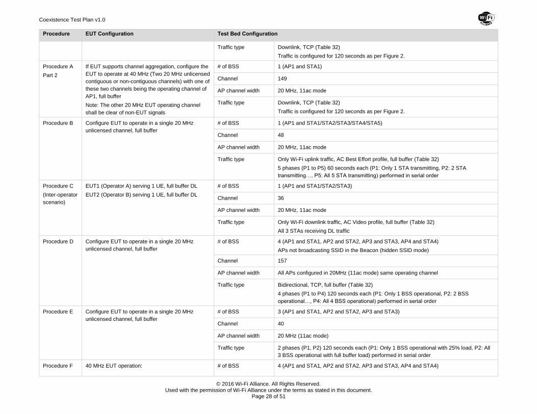
Traffic type Downlink, TCP (Table 32)
Traffic is configured for 120 seconds as per Figure 2.
Procedure A
Part 2
If EUT supports channel aggregation, configure the
EUT to operate at 40 MHz (Two 20 MHz unlicensed
contiguous or non-contiguous channels) with one of
these two channels being the operating channel of
AP1, full buffer
Note: The other 20 MHz EUT operating channel
shall be clear of non-EUT signals
# of BSS 1 (AP1 and STA1)
Channel 149
AP channel width 20 MHz, 11ac mode
Traffic type Downlink, TCP (Table 32)
Traffic is configured for 120 seconds as per Figure 2.
Procedure B Configure EUT to operate in a single 20 MHz
unlicensed channel, full buffer
# of BSS 1 (AP1 and STA1/STA2/STA3/STA4/STA5)
Channel 48
AP channel width 20 MHz, 11ac mode
Traffic type Only Wi-Fi uplink traffic, AC Best Effort profile, full buffer (Table 32)
5 phases (P1 to P5) 60 seconds each (P1: Only 1 STA transmitting, P2: 2 STA
transmitting…, P5: All 5 STA transmitting) performed in serial order
Procedure C
(Inter-operator
scenario)
EUT1 (Operator A) serving 1 UE, full buffer DL
EUT2 (Operator B) serving 1 UE, full buffer DL
# of BSS 1 (AP1 and STA1/STA2/STA3)
Channel 36
AP channel width 20 MHz, 11ac mode
Traffic type Only Wi-Fi downlink traffic, AC Video profile, full buffer (Table 32)
All 3 STAs receiving DL traffic
Procedure D Configure EUT to operate in a single 20 MHz
unlicensed channel, full buffer
# of BSS 4 (AP1 and STA1, AP2 and STA2, AP3 and STA3, AP4 and STA4)
APs not broadcasting SSID in the Beacon (hidden SSID mode)
Channel 157
AP channel width All APs configured in 20MHz (11ac mode) same operating channel
Traffic type Bidirectional, TCP, full buffer (Table 32)
4 phases (P1 to P4) 120 seconds each (P1: Only 1 BSS operational, P2: 2 BSS
operational…, P4: All 4 BSS operational) performed in serial order
Procedure E Configure EUT to operate in a single 20 MHz
unlicensed channel, full buffer
# of BSS 3 (AP1 and STA1, AP2 and STA2, AP3 and STA3)
Channel 40
AP channel width 20 MHz (11ac mode)
Traffic type 2 phases (P1, P2) 120 seconds each (P1: Only 1 BSS operational with 25% load, P2: All
3 BSS operational with full buffer load) performed in serial order
Procedure F 40 MHz EUT operation: # of BSS 4 (AP1 and STA1, AP2 and STA2, AP3 and STA3, AP4 and STA4)
Coexistence Test Plan v1.0
© 2016 Wi-Fi Alliance. All Rights Reserved. Used with the permission of Wi-Fi Alliance under the terms as stated in this document.
Page 29 of 51
Procedure EUT Configuration Test Bed Configuration
EUT1 (Operator A) serving 1 UE, full buffer DL.
If the EUT supports channel aggregation, the EUT
is configured for a single 40 MHz channel that
contends with the two 20 MHz Wi-Fi channels being
tested.
AP channel width and
Channel
Two 20 MHz adjacent channels are used for the test: channel 153 and 157
Traffic type Phase P1 (0 - 60 seconds):
AP1 occupy channel 153, full buffer downlink traffic to STA1
AP2, AP3, and AP4 occupy channel 157, full buffer downlink traffic to STA2, STA3 and STA4 respectively
Phase P2(0 - 60 seconds):
AP1 and AP2 occupy channel 153, full buffer downlink traffic to STA1 and STA2 respectively
AP3 occupy channel 157, full buffer downlink traffic to STA3
AP4 is turned OFF
Figure 2. Wi-Fi load variation (% load with ramp duration of 10 seconds)
Test Procedure
Wi-Fi calibration:
1. Wi-Fi calibration test is executed before each procedure specified in Table 13.
a. No LTE-U equipment should be operating during the calibration.
b. Record the Wi-Fi calibration result for each phase within a procedure.
Coexistence Test Plan v1.0
© 2016 Wi-Fi Alliance. All Rights Reserved. Used with the permission of Wi-Fi Alliance under the terms as stated in this document.
Page 30 of 51
c. For procedure F: An 802.11ac AP operating at 40 MHz is used for calibration in order to provide a comparison between 40 MHz LTE and 40 MHz 802.11ac.
EUT calibration:
1. The EUT calibration test is performed ONCE and is not to be repeated for each procedure. Measure and record the EUT's medium usage when it is loaded with full buffer traffic. It is expected that the EUT will utilize the channel to the maximum extent allowable.
Procedures A - F:
1. The EUT is configured and turned on. Procedure C uses two EUTs operated by different operators (operator A and operator B).
Restrict the EUT to operate on only one 20 MHz channel as specified in Table 13, except in procedure A Part 2 and procedure F where the EUT is configured to operate in the 40 MHz channel.
2. Full buffer, downlink traffic is established between the EUT and the LTE-U UE to ensure medium usage is as per the EUT calibration step above.
3. Ensure that the EUT is transmitting at maximum transmit power as declared in Table 4. Measure and record EUT's transmit power.
4. Configure one or more Wi-Fi networks to operate in the same channel(s) as the EUT as specified in Table 13.
5. Load the Wi-Fi operating channel by introducing the Wi-Fi traffic specified in Table 13.
6. Each AP is heard by its associated STAs at the respective test level being used.
7. Verify that all Wi-Fi nodes are heard by the LTE-U node at the test signal levels specified below.
Run 1: Test Level 1 Run 2: Test Level 2 Run 3: Test Level 3
8. Measure and record the Wi-Fi throughput achieved during each test procedure in the presence of the EUT.
9. Measure and record the EUT's medium usage during each phase of the procedure.
10. Measure and record the Medium Usage Adaptive Response Time (MUART) achieved during each phase of the procedure.
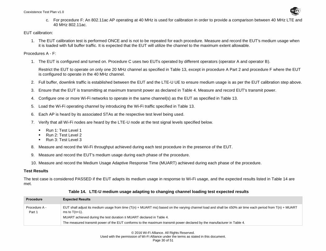
Test Results
The test case is considered PASSED if the EUT adapts its medium usage in response to Wi-Fi usage, and the expected results listed in Table 14 are met.
Table 14. LTE-U medium usage adapting to changing channel loading test expected results
Procedure Expected Results
Procedure A -
Part 1
EUT shall adjust its medium usage from time (T(n) + MUART ms) based on the varying channel load and shall be ≤50% air time each period from T(n) + MUART
ms to T(n+1).
MUART achieved during the test duration ≤ MUART declared in Table 4.
The measured transmit power of the EUT conforms to the maximum transmit power declared by the manufacturer in Table 4.
Coexistence Test Plan v1.0
© 2016 Wi-Fi Alliance. All Rights Reserved. Used with the permission of Wi-Fi Alliance under the terms as stated in this document.
Page 31 of 51
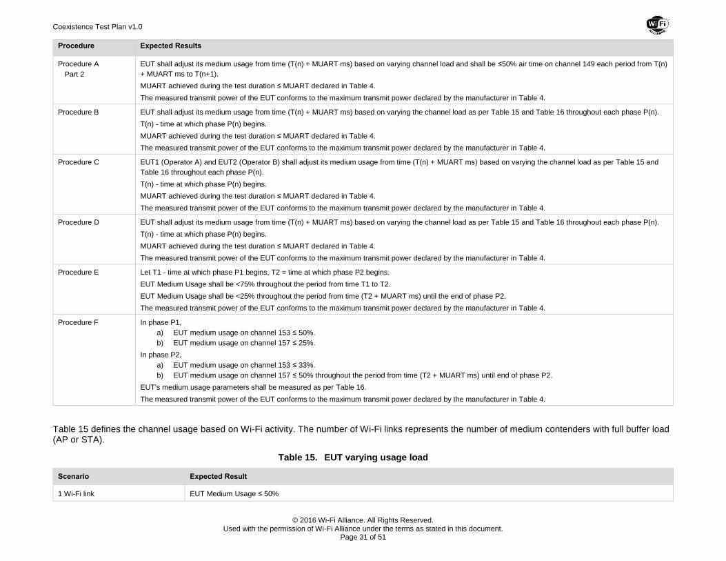
Procedure Expected Results
Procedure A
Part 2
EUT shall adjust its medium usage from time (T(n) + MUART ms) based on varying channel load and shall be ≤50% air time on channel 149 each period from T(n)
+ MUART ms to T(n+1).
MUART achieved during the test duration ≤ MUART declared in Table 4.
The measured transmit power of the EUT conforms to the maximum transmit power declared by the manufacturer in Table 4.
Procedure B EUT shall adjust its medium usage from time (T(n) + MUART ms) based on varying the channel load as per Table 15 and Table 16 throughout each phase P(n).
T(n) - time at which phase P(n) begins.
MUART achieved during the test duration ≤ MUART declared in Table 4.
The measured transmit power of the EUT conforms to the maximum transmit power declared by the manufacturer in Table 4.
Procedure C EUT1 (Operator A) and EUT2 (Operator B) shall adjust its medium usage from time (T(n) + MUART ms) based on varying the channel load as per Table 15 and
Table 16 throughout each phase P(n).
T(n) - time at which phase P(n) begins.
MUART achieved during the test duration ≤ MUART declared in Table 4.
The measured transmit power of the EUT conforms to the maximum transmit power declared by the manufacturer in Table 4.
Procedure D EUT shall adjust its medium usage from time (T(n) + MUART ms) based on varying the channel load as per Table 15 and Table 16 throughout each phase P(n).
T(n) - time at which phase P(n) begins.
MUART achieved during the test duration ≤ MUART declared in Table 4.
The measured transmit power of the EUT conforms to the maximum transmit power declared by the manufacturer in Table 4.
Procedure E Let T1 - time at which phase P1 begins, T2 = time at which phase P2 begins.
EUT Medium Usage shall be <75% throughout the period from time T1 to T2.
EUT Medium Usage shall be <25% throughout the period from time (T2 + MUART ms) until the end of phase P2.
The measured transmit power of the EUT conforms to the maximum transmit power declared by the manufacturer in Table 4.
Procedure F In phase P1,
a) EUT medium usage on channel 153 ≤ 50%.
b) EUT medium usage on channel 157 ≤ 25%.
In phase P2,
a) EUT medium usage on channel 153 ≤ 33%.
b) EUT medium usage on channel 157 ≤ 50% throughout the period from time (T2 + MUART ms) until end of phase P2.
EUT's medium usage parameters shall be measured as per Table 16.
The measured transmit power of the EUT conforms to the maximum transmit power declared by the manufacturer in Table 4.
Table 15 defines the channel usage based on Wi-Fi activity. The number of Wi-Fi links represents the number of medium contenders with full buffer load (AP or STA).
Table 15. EUT varying usage load
Scenario Expected Result
1 Wi-Fi link EUT Medium Usage ≤ 50%
Coexistence Test Plan v1.0
© 2016 Wi-Fi Alliance. All Rights Reserved. Used with the permission of Wi-Fi Alliance under the terms as stated in this document.
Page 32 of 51
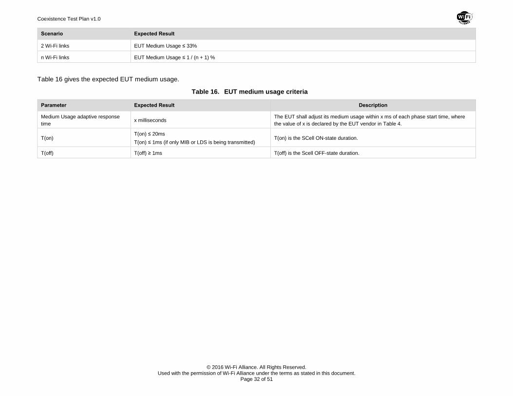
Scenario Expected Result
2 Wi-Fi links EUT Medium Usage ≤ 33%
n Wi-Fi links EUT Medium Usage ≤ 1 / (n + 1) %
Table 16 gives the expected EUT medium usage.
Table 16. EUT medium usage criteria
Parameter Expected Result Description
Medium Usage adaptive response
time x milliseconds
The EUT shall adjust its medium usage within x ms of each phase start time, where
the value of x is declared by the EUT vendor in Table 4.
T(on) T(on) ≤ 20ms
T(on) ≤ 1ms (if only MIB or LDS is being transmitted) T(on) is the SCell ON-state duration.
T(off) T(off) ≥ 1ms T(off) is the Scell OFF-state duration.
Coexistence Test Plan v1.0
© 2016 Wi-Fi Alliance. All Rights Reserved. Used with the permission of Wi-Fi Alliance under the terms as stated in this document.
Page 33 of 51
4.4 LTE-U Impact on Latency Sensitive Wi-Fi Traffic Test
Purpose and Description
This test determines the impact of LTE-U node operation on latency sensitive Wi-Fi applications such as VoIP. The test records the variations in KPIs in the presence and absence of an EUT under different load conditions. Unlicensed channels in U-NII-1 (5150 MHz -5250 MHz) and U-NII-3 (5725 MHz -5825 MHz) bands are used for this test.
This test case and expected results are based on WFA Voice Enterprise test plan that provides the data for one-way delay, jitter, packet loss for uplink and downlink Wi-Fi traffic.
References
Wi-Fi Alliance Voice Over Wi-Fi Enterprise Certification Program Test Plan v1.1
Test Environment
1 EUT
1 LTE-U UE
2 Wi-Fi CERTIFIED access points
6 Wi-Fi CERTIFIED ac stations
1 wireless sniffer
1 Wi-Fi data traffic generator
LinkLevel1 = LinkLevel2 = LinkLevel3 = LinkLevel4 = Test Level being used
Wi-Fi Benchmark
The Wi-Fi benchmark data for this test shall be established using the equipment and configurations specified in Appendix B.
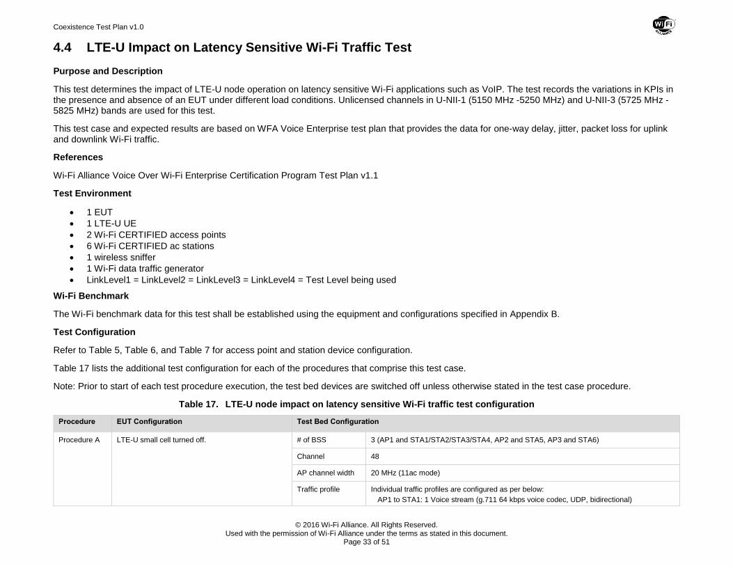
Test Configuration
Refer to Table 5, Table 6, and Table 7 for access point and station device configuration.
Table 17 lists the additional test configuration for each of the procedures that comprise this test case.
Note: Prior to start of each test procedure execution, the test bed devices are switched off unless otherwise stated in the test case procedure.
Table 17. LTE-U node impact on latency sensitive Wi-Fi traffic test configuration
Procedure EUT Configuration Test Bed Configuration
Procedure A LTE-U small cell turned off. # of BSS 3 (AP1 and STA1/STA2/STA3/STA4, AP2 and STA5, AP3 and STA6)
Channel 48
AP channel width 20 MHz (11ac mode)
Traffic profile Individual traffic profiles are configured as per below:
AP1 to STA1: 1 Voice stream (g.711 64 kbps voice codec, UDP, bidirectional)
Coexistence Test Plan v1.0
© 2016 Wi-Fi Alliance. All Rights Reserved. Used with the permission of Wi-Fi Alliance under the terms as stated in this document.
Page 34 of 51
Procedure EUT Configuration Test Bed Configuration
AP1 to STA2, STA3, STA4: 3 Voice streams EACH (g.711 64 kbps voice codec, UDP, bidirectional)
AP2 to STA5: Traffic load @ ~50% of the total channel capacity
AP3 to STA6: Full buffer, Downlink, UDP
Duration: 120 seconds
Procedure B EUT is configured and turned on.
Full buffer DL from EUT to LTE-U UE.
EUT replaces BSS#3 from Procedure A
# of BSS BSS#1 (AP1 and STA1, STA2, STA3, STA4) and BSS#2 (AP2 and STA5)
Channel 48
AP channel width 20 MHz (11ac mode)
Traffic profile Individual traffic profiles are configured as per below:
AP1 to STA1: 1 Voice stream (g.711 64kbps voice codec, UDP, bidirectional)
AP1 to STA2, STA3, STA4: 3 Voice streams EACH (g.711 64kbps voice codec, UDP, bidirectional)
AP2 to STA5: Traffic load @ ~50% of the total channel capacity
Duration: 120 seconds
Procedure C EUT configured and turned on. LTE-U UE
connected to EUT.
EUT traffic type has 3 phases 120 seconds each
(P1: full buffer load. P2: 50% load, P3: zero load).
Load definitions are specified in Table 24.
# of BSS 1 (AP1 and STA1)
Channel 149
AP channel width 20 MHz (11ac mode)
Traffic type Wi-Fi traffic type is Bidirectional, AC Voice profile, G.711 (64 kbps) voice codec (Table 32)
Duration: 300 seconds (traffic is introduced on Wi-Fi link 60 seconds into Phase P1)
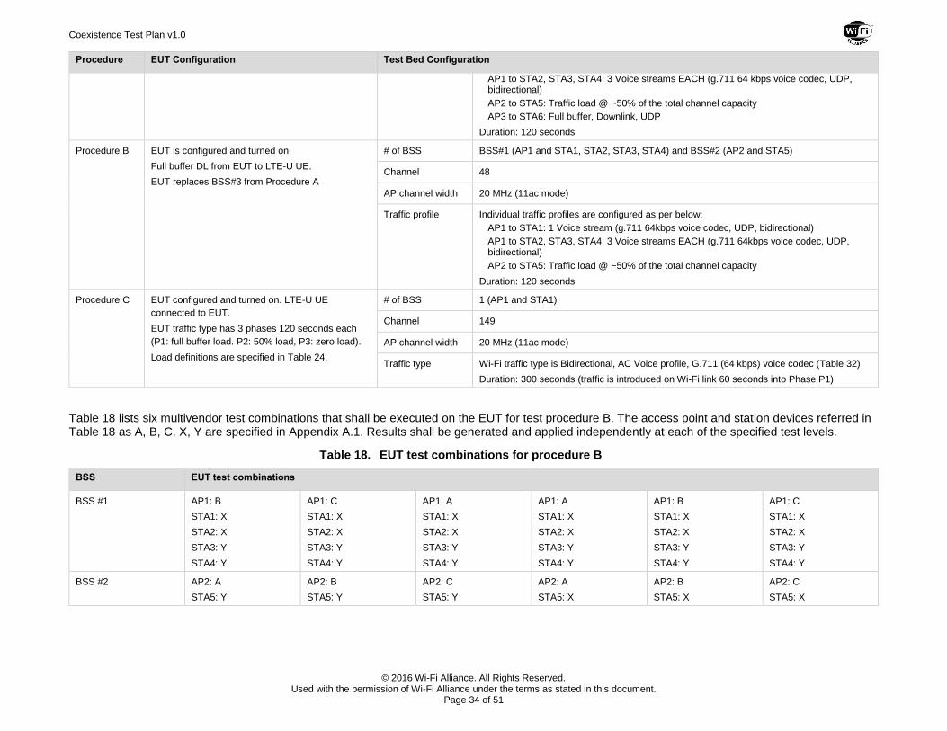
Table 18 lists six multivendor test combinations that shall be executed on the EUT for test procedure B. The access point and station devices referred in Table 18 as A, B, C, X, Y are specified in Appendix A.1. Results shall be generated and applied independently at each of the specified test levels.
Table 18. EUT test combinations for procedure B
BSS EUT test combinations
BSS #1 AP1: B
STA1: X
STA2: X
STA3: Y
STA4: Y
AP1: C
STA1: X
STA2: X
STA3: Y
STA4: Y
AP1: A
STA1: X
STA2: X
STA3: Y
STA4: Y
AP1: A
STA1: X
STA2: X
STA3: Y
STA4: Y
AP1: B
STA1: X
STA2: X
STA3: Y
STA4: Y
AP1: C
STA1: X
STA2: X
STA3: Y
STA4: Y
BSS #2 AP2: A
STA5: Y
AP2: B
STA5: Y
AP2: C
STA5: Y
AP2: A
STA5: X
AP2: B
STA5: X
AP2: C
STA5: X
Coexistence Test Plan v1.0
© 2016 Wi-Fi Alliance. All Rights Reserved. Used with the permission of Wi-Fi Alliance under the terms as stated in this document.
Page 35 of 51
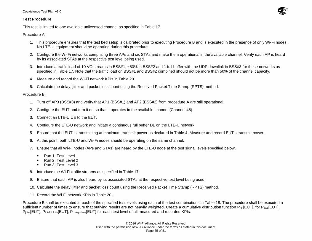
Test Procedure
This test is limited to one available unlicensed channel as specified in Table 17.
Procedure A:
1. This procedure ensures that the test bed setup is calibrated prior to executing Procedure B and is executed in the presence of only Wi-Fi nodes. No LTE-U equipment should be operating during this procedure.
2. Configure the Wi-Fi networks comprising three APs and six STAs and make them operational in the available channel. Verify each AP is heard by its associated STAs at the respective test level being used.
3. Introduce a traffic load of 10 VO streams in BSS#1, ~50% in BSS#2 and 1 full buffer with the UDP downlink in BSS#3 for these networks as specified in Table 17. Note that the traffic load on BSS#1 and BSS#2 combined should not be more than 50% of the channel capacity.
4. Measure and record the Wi-Fi network KPIs in Table 20.
5. Calculate the delay, jitter and packet loss count using the Received Packet Time Stamp (RPTS) method.
Procedure B:
1. Turn off AP3 (BSS#3) and verify that AP1 (BSS#1) and AP2 (BSS#2) from procedure A are still operational.
2. Configure the EUT and turn it on so that it operates in the available channel (Channel 48).
3. Connect an LTE-U UE to the EUT.
4. Configure the LTE-U network and initiate a continuous full buffer DL on the LTE-U network.
5. Ensure that the EUT is transmitting at maximum transmit power as declared in Table 4. Measure and record EUT's transmit power.
6. At this point, both LTE-U and Wi-Fi nodes should be operating on the same channel.
7. Ensure that all Wi-Fi nodes (APs and STAs) are heard by the LTE-U node at the test signal levels specified below.
Run 1: Test Level 1 Run 2: Test Level 2 Run 3: Test Level 3
8. Introduce the Wi-Fi traffic streams as specified in Table 17.
9. Ensure that each AP is also heard by its associated STAs at the respective test level being used.
10. Calculate the delay, jitter and packet loss count using the Received Packet Time Stamp (RPTS) method.
11. Record the Wi-Fi network KPIs in Table 20.
Procedure B shall be executed at each of the specified test levels using each of the test combinations in Table 18. The procedure shall be executed a sufficient number of times to ensure that outlying results are not heavily weighted. Create a cumulative distribution function Pkpi[EUT], for Powd[EUT], Pjitter[EUT], Ptotalpktloss[EUT], Pconspktloss[EUT] for each test level of all measured and recorded KPIs.
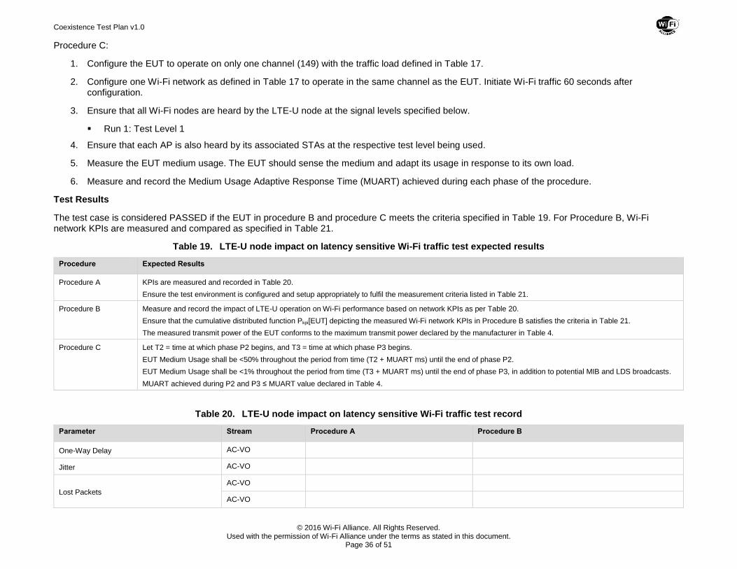
Coexistence Test Plan v1.0
© 2016 Wi-Fi Alliance. All Rights Reserved. Used with the permission of Wi-Fi Alliance under the terms as stated in this document.
Page 36 of 51
Procedure C:
1. Configure the EUT to operate on only one channel (149) with the traffic load defined in Table 17.
2. Configure one Wi-Fi network as defined in Table 17 to operate in the same channel as the EUT. Initiate Wi-Fi traffic 60 seconds after configuration.
3. Ensure that all Wi-Fi nodes are heard by the LTE-U node at the signal levels specified below.
Run 1: Test Level 1
4. Ensure that each AP is also heard by its associated STAs at the respective test level being used.
5. Measure the EUT medium usage. The EUT should sense the medium and adapt its usage in response to its own load.
6. Measure and record the Medium Usage Adaptive Response Time (MUART) achieved during each phase of the procedure.
Test Results
The test case is considered PASSED if the EUT in procedure B and procedure C meets the criteria specified in Table 19. For Procedure B, Wi-Fi network KPIs are measured and compared as specified in Table 21.
Table 19. LTE-U node impact on latency sensitive Wi-Fi traffic test expected results
Procedure Expected Results
Procedure A KPIs are measured and recorded in Table 20.
Ensure the test environment is configured and setup appropriately to fulfil the measurement criteria listed in Table 21.
Procedure B Measure and record the impact of LTE-U operation on Wi-Fi performance based on network KPIs as per Table 20.
Ensure that the cumulative distributed function Pkpi[EUT] depicting the measured Wi-Fi network KPIs in Procedure B satisfies the criteria in Table 21.
The measured transmit power of the EUT conforms to the maximum transmit power declared by the manufacturer in Table 4.
Procedure C Let T2 = time at which phase P2 begins, and T3 = time at which phase P3 begins.
EUT Medium Usage shall be <50% throughout the period from time (T2 + MUART ms) until the end of phase P2.
EUT Medium Usage shall be <1% throughout the period from time (T3 + MUART ms) until the end of phase P3, in addition to potential MIB and LDS broadcasts.
MUART achieved during P2 and P3 ≤ MUART value declared in Table 4.
Table 20. LTE-U node impact on latency sensitive Wi-Fi traffic test record
Parameter Stream Procedure A Procedure B
One-Way Delay AC-VO
Jitter AC-VO
Lost Packets
AC-VO
AC-VO
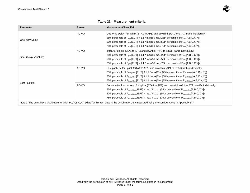
Coexistence Test Plan v1.0
© 2016 Wi-Fi Alliance. All Rights Reserved. Used with the permission of Wi-Fi Alliance under the terms as stated in this document.
Page 37 of 51
Table 21. Measurement criteria
Parameter Stream Measurement/Pass/Fail1
One-Way Delay
AC-VO One-Way Delay, for uplink (STA1 to AP1) and downlink (AP1 to STA1) traffic individually:
25th percentile of Powd[EUT] < 1.1 * max(50 ms, (25th percentile of Powd[A,B,C,X,Y]))
50th percentile of Powd[EUT] < 1.1 * max(50 ms, (50th percentile of Powd[A,B,C,X,Y]))
75th percentile of Powd[EUT] < 1.1 * max(50 ms, (75th percentile of Powd[A,B,C,X,Y]))
Jitter (delay variation)
AC-VO Jitter, for uplink (STA1 to AP1) and downlink (AP1 to STA1) traffic individually:
25th percentile of Pjitter[EUT] < 1.1 * max(50 ms, (25th percentile of Pjitter[A,B,C,X,Y]))
50th percentile of Pjitter[EUT] < 1.1 * max(50 ms, (50th percentile of Pjitter[A,B,C,X,Y]))
75th percentile of Pjitter[EUT] < 1.1 * max(50 ms, (75th percentile of Pjitter[A,B,C,X,Y]))
Lost Packets
AC-VO Lost packets, for uplink (STA1 to AP1) and downlink (AP1 to STA1) traffic individually:
25th percentile of Ptotalpktloss[EUT] ≤ 1.1 * max(1%, (25th percentile of Ptotalpktloss[A,B,C,X,Y]))
50th percentile of Ptotalpktloss[EUT] ≤ 1.1 * max(1%, (50th percentile of Ptotalpktloss[A,B,C,X,Y]))
75th percentile of Ptotalpktloss[EUT] ≤ 1.1 * max(1%, (75th percentile of Ptotalpktloss[A,B,C,X,Y]))
AC-VO Consecutive lost packets, for uplink (STA1 to AP1) and downlink (AP1 to STA1) traffic individually:
25th percentile of Pconspktloss[EUT] ≤ max(3, 1.1 * (25th percentile of Pconspktloss[A,B,C,X,Y]))
50th percentile of Pconspktloss[EUT] ≤ max(3, 1.1 * (50th percentile of Pconspktloss[A,B,C,X,Y]))
75th percentile of Pconspktloss[EUT] ≤ max(3, 1.1 * (75th percentile of Pconspktloss[A,B,C,X,Y]))
Note 1: The cumulative distribution function Pkpi[A,B,C,X,Y] data for this test case is the benchmark data measured using the configurations in Appendix B.3.
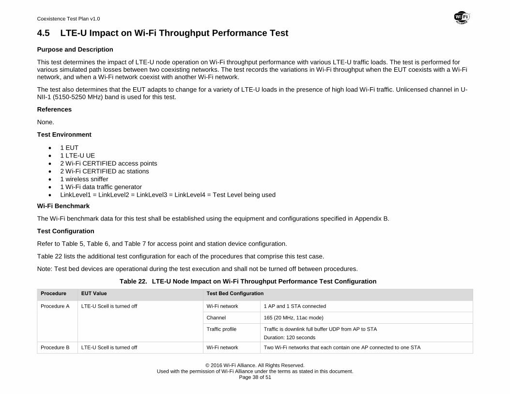
Coexistence Test Plan v1.0
© 2016 Wi-Fi Alliance. All Rights Reserved. Used with the permission of Wi-Fi Alliance under the terms as stated in this document.
Page 38 of 51
4.5 LTE-U Impact on Wi-Fi Throughput Performance Test
Purpose and Description
This test determines the impact of LTE-U node operation on Wi-Fi throughput performance with various LTE-U traffic loads. The test is performed for various simulated path losses between two coexisting networks. The test records the variations in Wi-Fi throughput when the EUT coexists with a Wi-Fi network, and when a Wi-Fi network coexist with another Wi-Fi network.
The test also determines that the EUT adapts to change for a variety of LTE-U loads in the presence of high load Wi-Fi traffic. Unlicensed channel in U-NII-1 (5150-5250 MHz) band is used for this test.
References
None.
Test Environment
1 EUT
1 LTE-U UE
2 Wi-Fi CERTIFIED access points
2 Wi-Fi CERTIFIED ac stations
1 wireless sniffer
1 Wi-Fi data traffic generator
LinkLevel1 = LinkLevel2 = LinkLevel3 = LinkLevel4 = Test Level being used
Wi-Fi Benchmark
The Wi-Fi benchmark data for this test shall be established using the equipment and configurations specified in Appendix B.
Test Configuration
Refer to Table 5, Table 6, and Table 7 for access point and station device configuration.
Table 22 lists the additional test configuration for each of the procedures that comprise this test case.
Note: Test bed devices are operational during the test execution and shall not be turned off between procedures.
Table 22. LTE-U Node Impact on Wi-Fi Throughput Performance Test Configuration
Procedure EUT Value Test Bed Configuration
Procedure A LTE-U Scell is turned off Wi-Fi network 1 AP and 1 STA connected
Channel 165 (20 MHz, 11ac mode)
Traffic profile Traffic is downlink full buffer UDP from AP to STA
Duration: 120 seconds
Procedure B LTE-U Scell is turned off Wi-Fi network Two Wi-Fi networks that each contain one AP connected to one STA
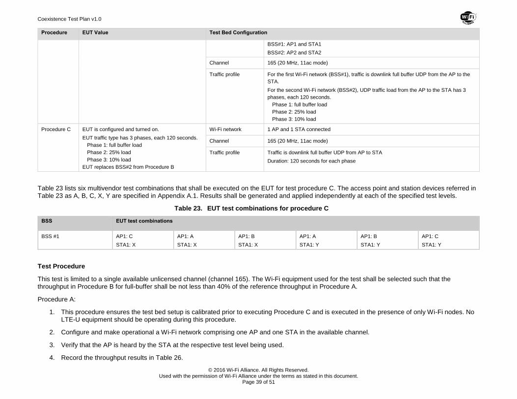
Coexistence Test Plan v1.0
© 2016 Wi-Fi Alliance. All Rights Reserved. Used with the permission of Wi-Fi Alliance under the terms as stated in this document.
Page 39 of 51
Procedure EUT Value Test Bed Configuration
BSS#1: AP1 and STA1
BSS#2: AP2 and STA2
Channel 165 (20 MHz, 11ac mode)
Traffic profile For the first Wi-Fi network (BSS#1), traffic is downlink full buffer UDP from the AP to the
STA.
For the second Wi-Fi network (BSS#2), UDP traffic load from the AP to the STA has 3
phases, each 120 seconds.
Phase 1: full buffer load
Phase 2: 25% load
Phase 3: 10% load
Procedure C EUT is configured and turned on.
EUT traffic type has 3 phases, each 120 seconds.
Phase 1: full buffer load
Phase 2: 25% load
Phase 3: 10% load
EUT replaces BSS#2 from Procedure B
Wi-Fi network 1 AP and 1 STA connected
Channel 165 (20 MHz, 11ac mode)
Traffic profile Traffic is downlink full buffer UDP from AP to STA
Duration: 120 seconds for each phase
Table 23 lists six multivendor test combinations that shall be executed on the EUT for test procedure C. The access point and station devices referred in Table 23 as A, B, C, X, Y are specified in Appendix A.1. Results shall be generated and applied independently at each of the specified test levels.
Table 23. EUT test combinations for procedure C
BSS EUT test combinations
BSS #1 AP1: C
STA1: X
AP1: A
STA1: X
AP1: B
STA1: X
AP1: A
STA1: Y
AP1: B
STA1: Y
AP1: C
STA1: Y
Test Procedure
This test is limited to a single available unlicensed channel (channel 165). The Wi-Fi equipment used for the test shall be selected such that the throughput in Procedure B for full-buffer shall be not less than 40% of the reference throughput in Procedure A.
Procedure A:
1. This procedure ensures the test bed setup is calibrated prior to executing Procedure C and is executed in the presence of only Wi-Fi nodes. No LTE-U equipment should be operating during this procedure.
2. Configure and make operational a Wi-Fi network comprising one AP and one STA in the available channel.
3. Verify that the AP is heard by the STA at the respective test level being used.
4. Record the throughput results in Table 26.
Coexistence Test Plan v1.0
© 2016 Wi-Fi Alliance. All Rights Reserved. Used with the permission of Wi-Fi Alliance under the terms as stated in this document.
Page 40 of 51
Procedure B:
1. This procedure ensures the test bed setup is calibrated prior to executing Procedure C and is executed in the presence of only Wi-Fi nodes. No LTE-U equipment should be operating during this procedure.
2. Configure and make operational a second Wi-Fi network comprising one AP and one STA operating in the same channel as the first.
3. Verify that the Wi-Fi AP is heard by its associated STA at the following test signal levels.
Run 1: Test Level 2 Run 2: Test Level 3
4. Configure the UDP traffic on the second network with each of the traffic loads specified in Table 24 for each phase. Refer to section 2.2.2 for how to calculate the percentage load.
5. Record the throughput results in Table 26.
Procedure C:
1. Remove the second Wi-Fi network and replace it with the EUT.
2. Configure and make operational an LTE-U network comprising an EUT and a LTE-U UE on channel 165.
3. Configure the UDP traffic of the LTE-U network with each of the traffic loads specified in Table 24 for each phase. Refer to section 2.2.2 for how to calculate the percentage load.
4. Ensure that the EUT is transmitting at maximum transmit power as declared in Table 4. Measure and record EUT's transmit power.
5. Verify that the Wi-Fi AP is heard by the STA at the respective test level.
6. Verify that the Wi-Fi nodes (AP and STA) are heard by the EUT at the test signal levels listed below.
Run 1: Test Level 2 Run 2: Test Level 3
7. Record the throughput and the EUT medium usage results in Table 26.
8. Measure and record the Medium Usage Adaptive Response Time (MUART) achieved during phase P2 and P3 of the procedure.
9. Verify that the EUT senses the medium and adapts in response to its own load.
Procedure C shall be executed at test level 2 and test level 3 using each of the test combinations in Table 23. The procedure shall be executed a sufficient number of times to ensure that outlying results are not heavily weighted. Create a cumulative distribution function PphaseN[EUT] for the measured throughput at each test level.
Table 24 defines the traffic loading terms used in this test case.
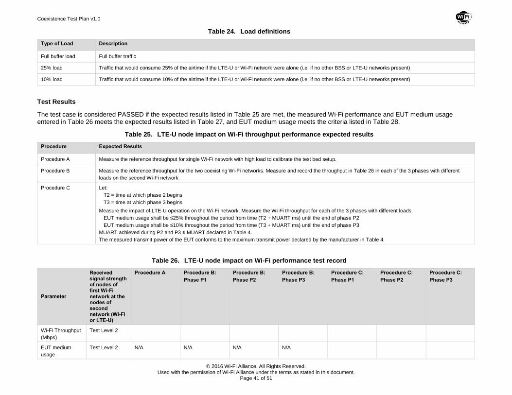
Coexistence Test Plan v1.0
© 2016 Wi-Fi Alliance. All Rights Reserved. Used with the permission of Wi-Fi Alliance under the terms as stated in this document.
Page 41 of 51
Table 24. Load definitions
Type of Load Description
Full buffer load Full buffer traffic
25% load Traffic that would consume 25% of the airtime if the LTE-U or Wi-Fi network were alone (i.e. if no other BSS or LTE-U networks present)
10% load Traffic that would consume 10% of the airtime if the LTE-U or Wi-Fi network were alone (i.e. if no other BSS or LTE-U networks present)
Test Results
The test case is considered PASSED if the expected results listed in Table 25 are met, the measured Wi-Fi performance and EUT medium usage entered in Table 26 meets the expected results listed in Table 27, and EUT medium usage meets the criteria listed in Table 28.
Table 25. LTE-U node impact on Wi-Fi throughput performance expected results
Procedure Expected Results
Procedure A Measure the reference throughput for single Wi-Fi network with high load to calibrate the test bed setup.
Procedure B Measure the reference throughput for the two coexisting Wi-Fi networks. Measure and record the throughput in Table 26 in each of the 3 phases with different
loads on the second Wi-Fi network.
Procedure C Let:
T2 = time at which phase 2 begins
T3 = time at which phase 3 begins
Measure the impact of LTE-U operation on the Wi-Fi network. Measure the Wi-Fi throughput for each of the 3 phases with different loads.
EUT medium usage shall be ≤25% throughout the period from time (T2 + MUART ms) until the end of phase P2
EUT medium usage shall be ≤10% throughout the period from time (T3 + MUART ms) until the end of phase P3
MUART achieved during P2 and P3 ≤ MUART declared in Table 4.
The measured transmit power of the EUT conforms to the maximum transmit power declared by the manufacturer in Table 4.
Table 26. LTE-U node impact on Wi-Fi performance test record
Parameter
Received signal strength of nodes of first Wi-Fi network at the nodes of second network (Wi-Fi or LTE-U)
Procedure A Procedure B:
Phase P1
Procedure B:
Phase P2
Procedure B:
Phase P3
Procedure C:
Phase P1
Procedure C:
Phase P2
Procedure C:
Phase P3
Wi-Fi Throughput
(Mbps)
Test Level 2
EUT medium
usage
Test Level 2 N/A N/A N/A N/A
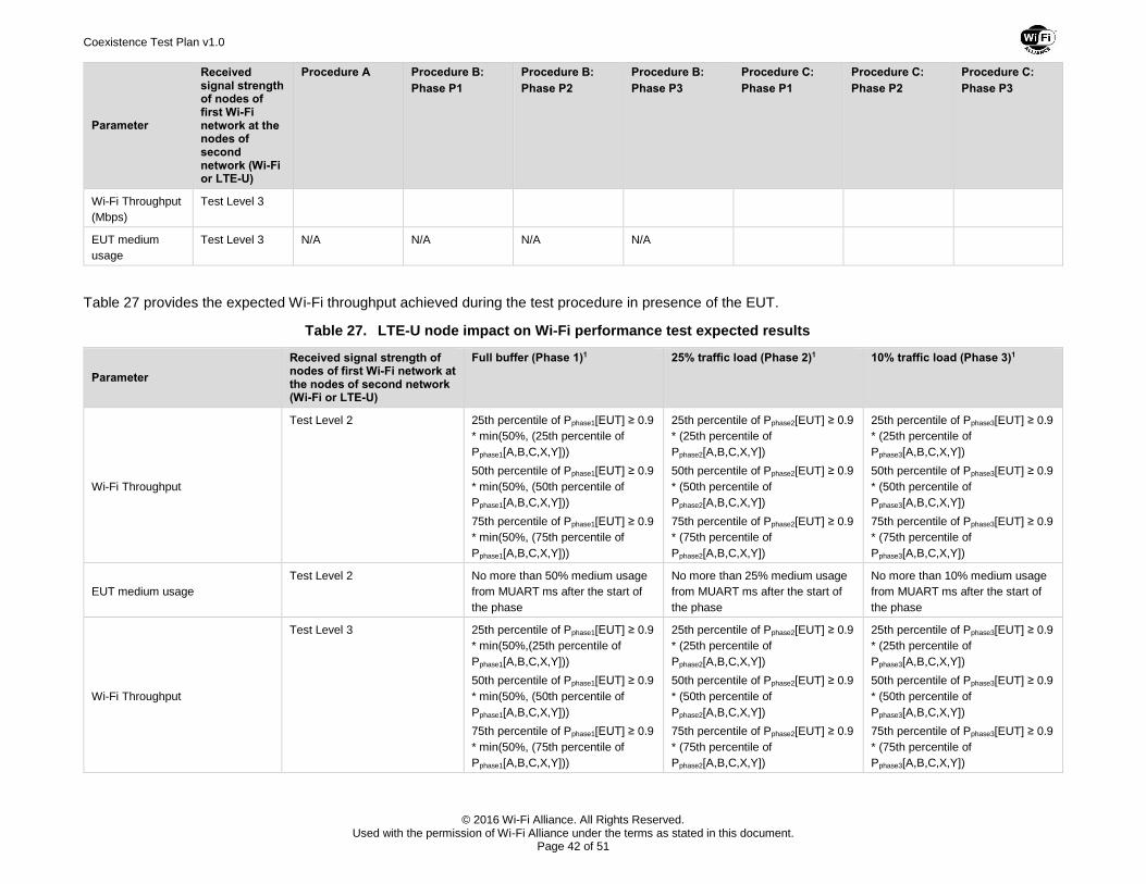
Coexistence Test Plan v1.0
© 2016 Wi-Fi Alliance. All Rights Reserved. Used with the permission of Wi-Fi Alliance under the terms as stated in this document.
Page 42 of 51
Parameter
Received signal strength of nodes of first Wi-Fi network at the nodes of second network (Wi-Fi or LTE-U)
Procedure A Procedure B:
Phase P1
Procedure B:
Phase P2
Procedure B:
Phase P3
Procedure C:
Phase P1
Procedure C:
Phase P2
Procedure C:
Phase P3
Wi-Fi Throughput
(Mbps)
Test Level 3
EUT medium
usage
Test Level 3 N/A N/A N/A N/A
Table 27 provides the expected Wi-Fi throughput achieved during the test procedure in presence of the EUT.
Table 27. LTE-U node impact on Wi-Fi performance test expected results
Parameter
Received signal strength of nodes of first Wi-Fi network at the nodes of second network (Wi-Fi or LTE-U)
Full buffer (Phase 1)1 25% traffic load (Phase 2)1 10% traffic load (Phase 3)1
Wi-Fi Throughput
Test Level 2 25th percentile of Pphase1[EUT] ≥ 0.9
* min(50%, (25th percentile of
Pphase1[A,B,C,X,Y]))
50th percentile of Pphase1[EUT] ≥ 0.9
* min(50%, (50th percentile of
Pphase1[A,B,C,X,Y]))
75th percentile of Pphase1[EUT] ≥ 0.9
* min(50%, (75th percentile of
Pphase1[A,B,C,X,Y]))
25th percentile of Pphase2[EUT] ≥ 0.9
* (25th percentile of
Pphase2[A,B,C,X,Y])
50th percentile of Pphase2[EUT] ≥ 0.9
* (50th percentile of
Pphase2[A,B,C,X,Y])
75th percentile of Pphase2[EUT] ≥ 0.9
* (75th percentile of
Pphase2[A,B,C,X,Y])
25th percentile of Pphase3[EUT] ≥ 0.9
* (25th percentile of
Pphase3[A,B,C,X,Y])
50th percentile of Pphase3[EUT] ≥ 0.9
* (50th percentile of
Pphase3[A,B,C,X,Y])
75th percentile of Pphase3[EUT] ≥ 0.9
* (75th percentile of
Pphase3[A,B,C,X,Y])
EUT medium usage
Test Level 2 No more than 50% medium usage
from MUART ms after the start of
the phase
No more than 25% medium usage
from MUART ms after the start of
the phase
No more than 10% medium usage
from MUART ms after the start of
the phase
Wi-Fi Throughput
Test Level 3 25th percentile of Pphase1[EUT] ≥ 0.9
* min(50%,(25th percentile of
Pphase1[A,B,C,X,Y]))
50th percentile of Pphase1[EUT] ≥ 0.9
* min(50%, (50th percentile of
Pphase1[A,B,C,X,Y]))
75th percentile of Pphase1[EUT] ≥ 0.9
* min(50%, (75th percentile of
Pphase1[A,B,C,X,Y]))
25th percentile of Pphase2[EUT] ≥ 0.9
* (25th percentile of
Pphase2[A,B,C,X,Y])
50th percentile of Pphase2[EUT] ≥ 0.9
* (50th percentile of
Pphase2[A,B,C,X,Y])
75th percentile of Pphase2[EUT] ≥ 0.9
* (75th percentile of
Pphase2[A,B,C,X,Y])
25th percentile of Pphase3[EUT] ≥ 0.9
* (25th percentile of
Pphase3[A,B,C,X,Y])
50th percentile of Pphase3[EUT] ≥ 0.9
* (50th percentile of
Pphase3[A,B,C,X,Y])
75th percentile of Pphase3[EUT] ≥ 0.9
* (75th percentile of
Pphase3[A,B,C,X,Y])
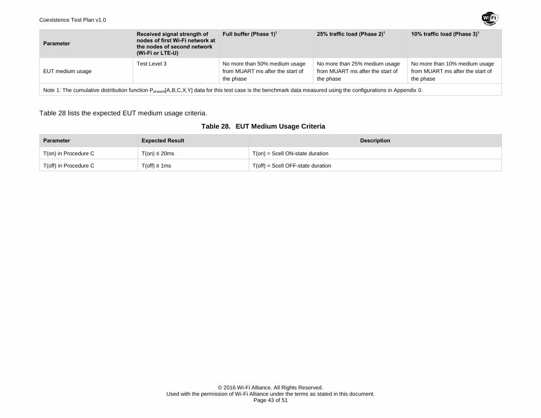
Coexistence Test Plan v1.0
© 2016 Wi-Fi Alliance. All Rights Reserved. Used with the permission of Wi-Fi Alliance under the terms as stated in this document.
Page 43 of 51
Parameter
Received signal strength of nodes of first Wi-Fi network at the nodes of second network (Wi-Fi or LTE-U)
Full buffer (Phase 1)1 25% traffic load (Phase 2)1 10% traffic load (Phase 3)1
EUT medium usage
Test Level 3 No more than 50% medium usage
from MUART ms after the start of
the phase
No more than 25% medium usage
from MUART ms after the start of
the phase
No more than 10% medium usage
from MUART ms after the start of
the phase
Note 1: The cumulative distribution function PphaseN[A,B,C,X,Y] data for this test case is the benchmark data measured using the configurations in Appendix 0.
Table 28 lists the expected EUT medium usage criteria.
Table 28. EUT Medium Usage Criteria
Parameter Expected Result Description
T(on) in Procedure C T(on) ≤ 20ms T(on) = Scell ON-state duration
T(off) in Procedure C T(off) ≥ 1ms T(off) = Scell OFF-state duration
Coexistence Test Plan v1.0
© 2016 Wi-Fi Alliance. All Rights Reserved. Used with the permission of Wi-Fi Alliance under the terms as stated in this document.
Page 44 of 51
Appendix A Test Bed Products (Normative)
A.1 Test Bed Equipment
Refer to the following document for detailed information about the test bed equipment used in the coexistence test cases in this test plan.
https://www.wi-fi.org/coexistence-test-equipment-list
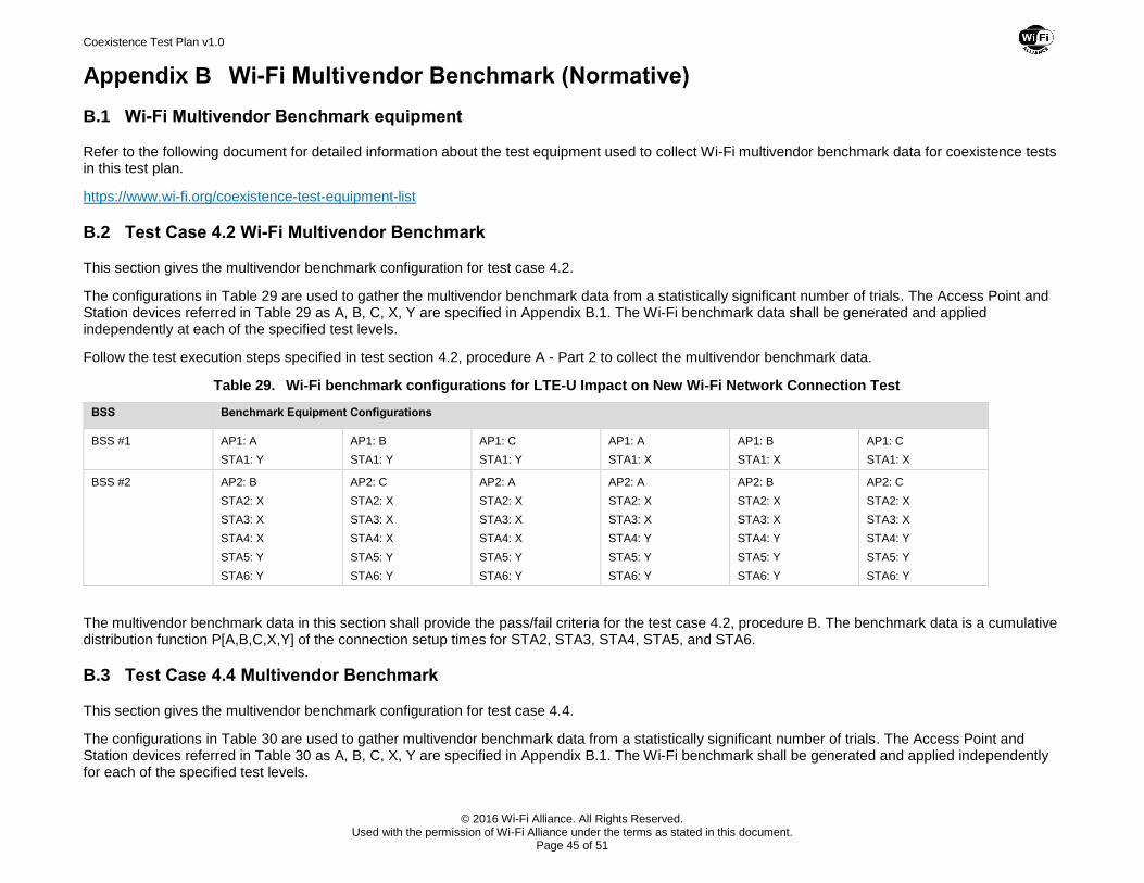
Coexistence Test Plan v1.0
© 2016 Wi-Fi Alliance. All Rights Reserved. Used with the permission of Wi-Fi Alliance under the terms as stated in this document.
Page 45 of 51
Appendix B Wi-Fi Multivendor Benchmark (Normative)
B.1 Wi-Fi Multivendor Benchmark equipment
Refer to the following document for detailed information about the test equipment used to collect Wi-Fi multivendor benchmark data for coexistence tests in this test plan.
https://www.wi-fi.org/coexistence-test-equipment-list
B.2 Test Case 4.2 Wi-Fi Multivendor Benchmark
This section gives the multivendor benchmark configuration for test case 4.2.
The configurations in Table 29 are used to gather the multivendor benchmark data from a statistically significant number of trials. The Access Point and Station devices referred in Table 29 as A, B, C, X, Y are specified in Appendix B.1. The Wi-Fi benchmark data shall be generated and applied independently at each of the specified test levels.
Follow the test execution steps specified in test section 4.2, procedure A - Part 2 to collect the multivendor benchmark data.
Table 29. Wi-Fi benchmark configurations for LTE-U Impact on New Wi-Fi Network Connection Test
BSS Benchmark Equipment Configurations
BSS #1 AP1: A
STA1: Y
AP1: B
STA1: Y
AP1: C
STA1: Y
AP1: A
STA1: X
AP1: B
STA1: X
AP1: C
STA1: X
BSS #2 AP2: B
STA2: X
STA3: X
STA4: X
STA5: Y
STA6: Y
AP2: C
STA2: X
STA3: X
STA4: X
STA5: Y
STA6: Y
AP2: A
STA2: X
STA3: X
STA4: X
STA5: Y
STA6: Y
AP2: A
STA2: X
STA3: X
STA4: Y
STA5: Y
STA6: Y
AP2: B
STA2: X
STA3: X
STA4: Y
STA5: Y
STA6: Y
AP2: C
STA2: X
STA3: X
STA4: Y
STA5: Y
STA6: Y
The multivendor benchmark data in this section shall provide the pass/fail criteria for the test case 4.2, procedure B. The benchmark data is a cumulative distribution function P[A,B,C,X,Y] of the connection setup times for STA2, STA3, STA4, STA5, and STA6.
B.3 Test Case 4.4 Multivendor Benchmark
This section gives the multivendor benchmark configuration for test case 4.4.
The configurations in Table 30 are used to gather multivendor benchmark data from a statistically significant number of trials. The Access Point and Station devices referred in Table 30 as A, B, C, X, Y are specified in Appendix B.1. The Wi-Fi benchmark shall be generated and applied independently for each of the specified test levels.
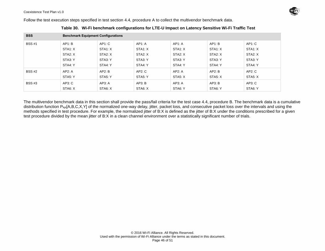
Coexistence Test Plan v1.0
© 2016 Wi-Fi Alliance. All Rights Reserved. Used with the permission of Wi-Fi Alliance under the terms as stated in this document.
Page 46 of 51
Follow the test execution steps specified in test section 4.4, procedure A to collect the multivendor benchmark data.
Table 30. Wi-Fi benchmark configurations for LTE-U Impact on Latency Sensitive Wi-Fi Traffic Test
BSS Benchmark Equipment Configurations
BSS #1 AP1: B
STA1: X
STA2: X
STA3: Y
STA4: Y
AP1: C
STA1: X
STA2: X
STA3: Y
STA4: Y
AP1: A
STA1: X
STA2: X
STA3: Y
STA4: Y
AP1: A
STA1: X
STA2: X
STA3: Y
STA4: Y
AP1: B
STA1: X
STA2: X
STA3: Y
STA4: Y
AP1: C
STA1: X
STA2: X
STA3: Y
STA4: Y
BSS #2 AP2: A
STA5: Y
AP2: B
STA5: Y
AP2: C
STA5: Y
AP2: A
STA5: X
AP2: B
STA5: X
AP2: C
STA5: X
BSS #3 AP3: C
STA6: X
AP3: A
STA6: X
AP3: B
STA6: X
AP3: A
STA6: Y
AP3: B
STA6: Y
AP3: C
STA6: Y
The multivendor benchmark data in this section shall provide the pass/fail criteria for the test case 4.4, procedure B. The benchmark data is a cumulative distribution function Pkpi[A,B,C,X,Y] of the normalized one-way delay, jitter, packet loss, and consecutive packet loss over the intervals and using the methods specified in test procedure. For example, the normalized jitter of B:X is defined as the jitter of B:X under the conditions prescribed for a given test procedure divided by the mean jitter of B:X in a clean channel environment over a statistically significant number of trials.
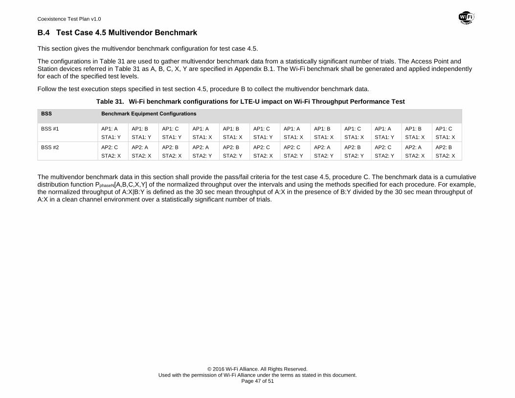
Coexistence Test Plan v1.0
© 2016 Wi-Fi Alliance. All Rights Reserved. Used with the permission of Wi-Fi Alliance under the terms as stated in this document.
Page 47 of 51
B.4 Test Case 4.5 Multivendor Benchmark
This section gives the multivendor benchmark configuration for test case 4.5.
The configurations in Table 31 are used to gather multivendor benchmark data from a statistically significant number of trials. The Access Point and Station devices referred in Table 31 as A, B, C, X, Y are specified in Appendix B.1. The Wi-Fi benchmark shall be generated and applied independently for each of the specified test levels.
Follow the test execution steps specified in test section 4.5, procedure B to collect the multivendor benchmark data.
Table 31. Wi-Fi benchmark configurations for LTE-U impact on Wi-Fi Throughput Performance Test
BSS Benchmark Equipment Configurations
BSS #1 AP1: A
STA1: Y
AP1: B
STA1: Y
AP1: C
STA1: Y
AP1: A
STA1: X
AP1: B
STA1: X
AP1: C
STA1: Y
AP1: A
STA1: X
AP1: B
STA1: X
AP1: C
STA1: X
AP1: A
STA1: Y
AP1: B
STA1: X
AP1: C
STA1: X
BSS #2 AP2: C
STA2: X
AP2: A
STA2: X
AP2: B
STA2: X
AP2: A
STA2: Y
AP2: B
STA2: Y
AP2: C
STA2: X
AP2: C
STA2: Y
AP2: A
STA2: Y
AP2: B
STA2: Y
AP2: C
STA2: Y
AP2: A
STA2: X
AP2: B
STA2: X
The multivendor benchmark data in this section shall provide the pass/fail criteria for the test case 4.5, procedure C. The benchmark data is a cumulative distribution function PphaseN[A,B,C,X,Y] of the normalized throughput over the intervals and using the methods specified for each procedure. For example, the normalized throughput of A:X|B:Y is defined as the 30 sec mean throughput of A:X in the presence of B:Y divided by the 30 sec mean throughput of A:X in a clean channel environment over a statistically significant number of trials.
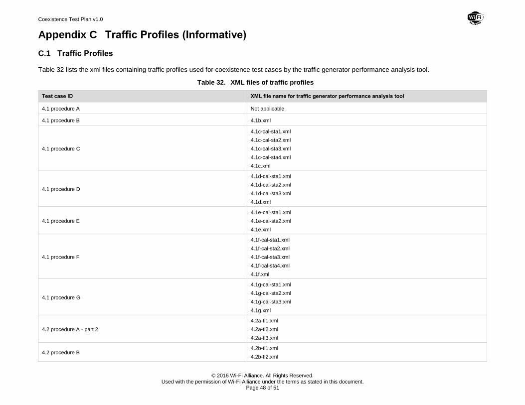
Coexistence Test Plan v1.0
© 2016 Wi-Fi Alliance. All Rights Reserved. Used with the permission of Wi-Fi Alliance under the terms as stated in this document.
Page 48 of 51
Appendix C Traffic Profiles (Informative)
C.1 Traffic Profiles
Table 32 lists the xml files containing traffic profiles used for coexistence test cases by the traffic generator performance analysis tool.
Table 32. XML files of traffic profiles
Test case ID XML file name for traffic generator performance analysis tool
4.1 procedure A Not applicable
4.1 procedure B 4.1b.xml
4.1 procedure C
4.1c-cal-sta1.xml
4.1c-cal-sta2.xml
4.1c-cal-sta3.xml
4.1c-cal-sta4.xml
4.1c.xml
4.1 procedure D
4.1d-cal-sta1.xml
4.1d-cal-sta2.xml
4.1d-cal-sta3.xml
4.1d.xml
4.1 procedure E
4.1e-cal-sta1.xml
4.1e-cal-sta2.xml
4.1e.xml
4.1 procedure F
4.1f-cal-sta1.xml
4.1f-cal-sta2.xml
4.1f-cal-sta3.xml
4.1f-cal-sta4.xml
4.1f.xml
4.1 procedure G
4.1g-cal-sta1.xml
4.1g-cal-sta2.xml
4.1g-cal-sta3.xml
4.1g.xml
4.2 procedure A - part 2
4.2a-tl1.xml
4.2a-tl2.xml
4.2a-tl3.xml
4.2 procedure B 4.2b-tl1.xml
4.2b-tl2.xml
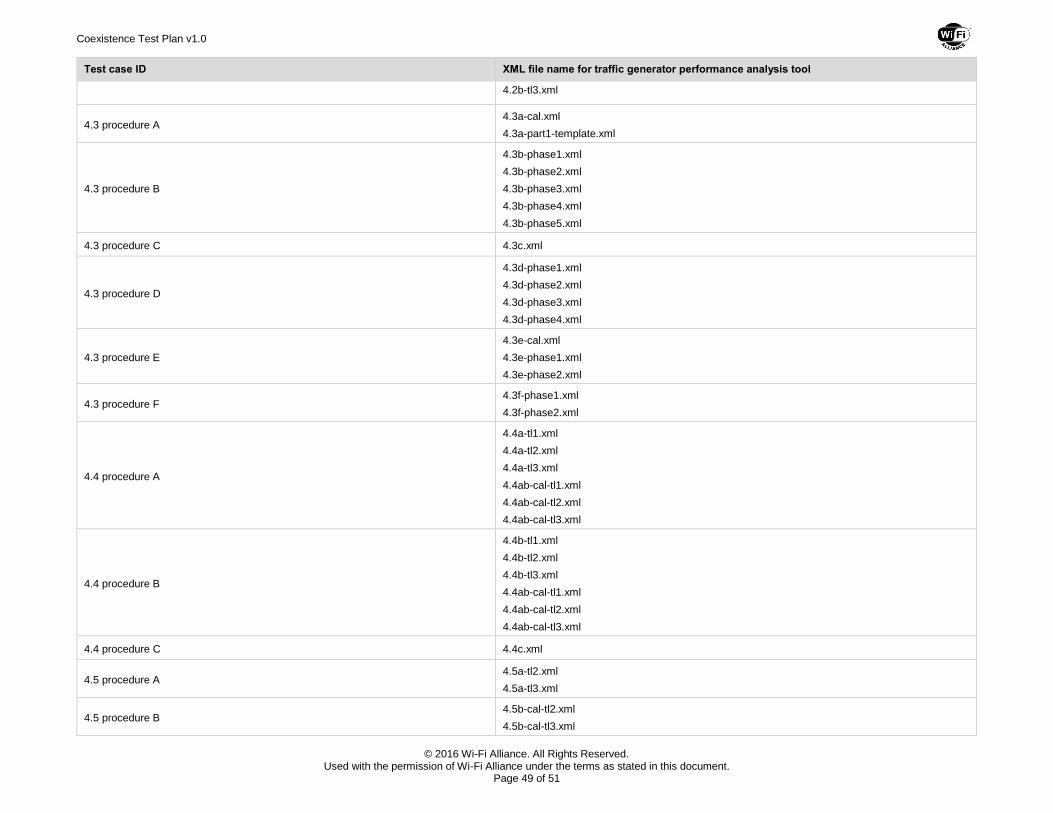
Coexistence Test Plan v1.0
© 2016 Wi-Fi Alliance. All Rights Reserved. Used with the permission of Wi-Fi Alliance under the terms as stated in this document.
Page 49 of 51
Test case ID XML file name for traffic generator performance analysis tool
4.2b-tl3.xml
4.3 procedure A 4.3a-cal.xml
4.3a-part1-template.xml
4.3 procedure B
4.3b-phase1.xml
4.3b-phase2.xml
4.3b-phase3.xml
4.3b-phase4.xml
4.3b-phase5.xml
4.3 procedure C 4.3c.xml
4.3 procedure D
4.3d-phase1.xml
4.3d-phase2.xml
4.3d-phase3.xml
4.3d-phase4.xml
4.3 procedure E
4.3e-cal.xml
4.3e-phase1.xml
4.3e-phase2.xml
4.3 procedure F 4.3f-phase1.xml
4.3f-phase2.xml
4.4 procedure A
4.4a-tl1.xml
4.4a-tl2.xml
4.4a-tl3.xml
4.4ab-cal-tl1.xml
4.4ab-cal-tl2.xml
4.4ab-cal-tl3.xml
4.4 procedure B
4.4b-tl1.xml
4.4b-tl2.xml
4.4b-tl3.xml
4.4ab-cal-tl1.xml
4.4ab-cal-tl2.xml
4.4ab-cal-tl3.xml
4.4 procedure C 4.4c.xml
4.5 procedure A 4.5a-tl2.xml
4.5a-tl3.xml
4.5 procedure B 4.5b-cal-tl2.xml
4.5b-cal-tl3.xml
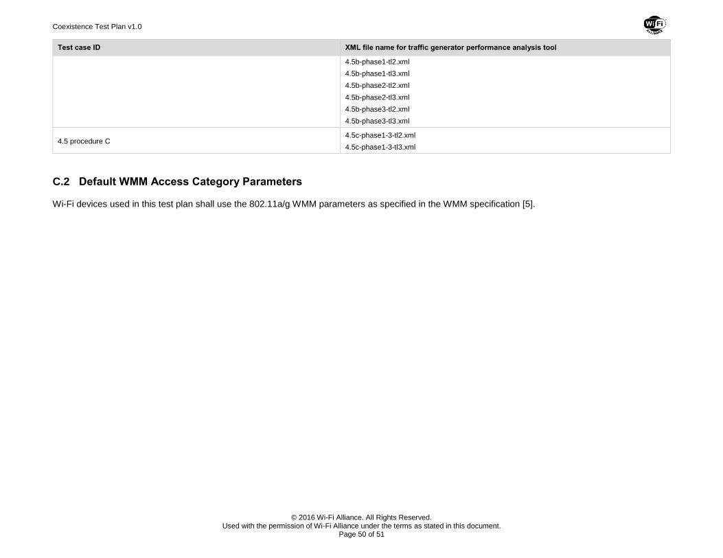
Coexistence Test Plan v1.0
© 2016 Wi-Fi Alliance. All Rights Reserved. Used with the permission of Wi-Fi Alliance under the terms as stated in this document.
Page 50 of 51
Test case ID XML file name for traffic generator performance analysis tool
4.5b-phase1-tl2.xml
4.5b-phase1-tl3.xml
4.5b-phase2-tl2.xml
4.5b-phase2-tl3.xml
4.5b-phase3-tl2.xml
4.5b-phase3-tl3.xml
4.5 procedure C 4.5c-phase1-3-tl2.xml
4.5c-phase1-3-tl3.xml
C.2 Default WMM Access Category Parameters
Wi-Fi devices used in this test plan shall use the 802.11a/g WMM parameters as specified in the WMM specification [5].
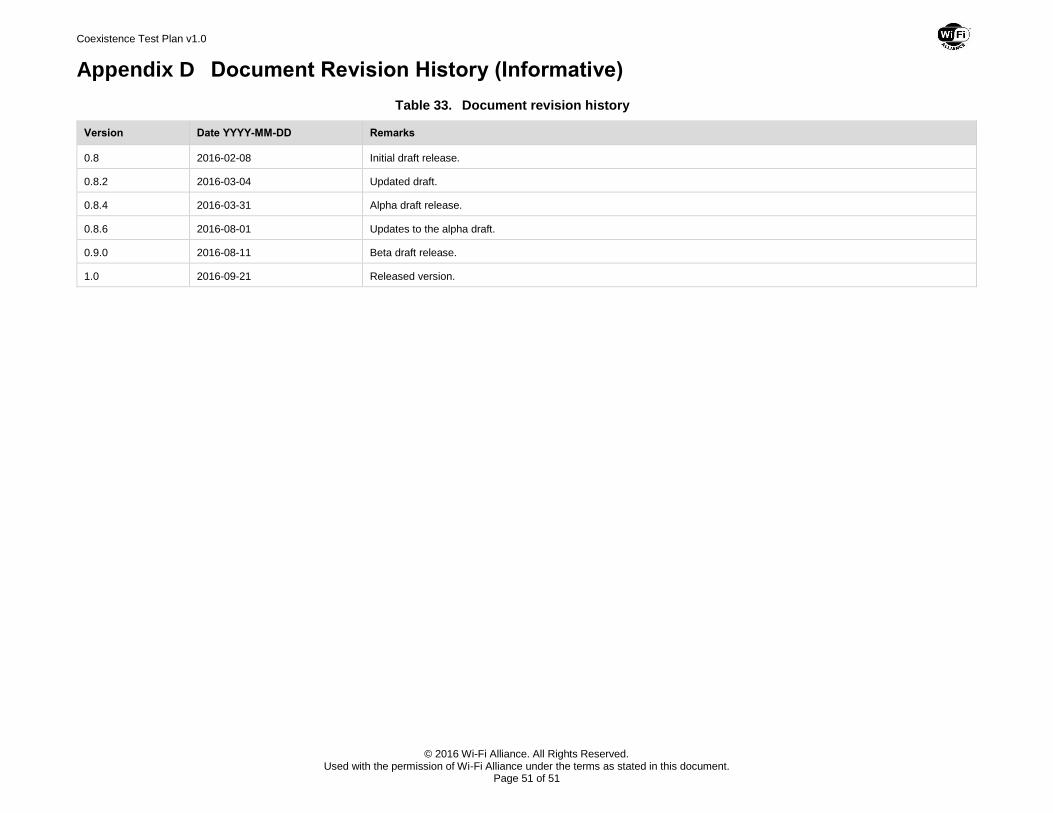
Coexistence Test Plan v1.0
© 2016 Wi-Fi Alliance. All Rights Reserved. Used with the permission of Wi-Fi Alliance under the terms as stated in this document.
Page 51 of 51
Appendix D Document Revision History (Informative)
Table 33. Document revision history
Version Date YYYY-MM-DD Remarks
0.8 2016-02-08 Initial draft release.
0.8.2 2016-03-04 Updated draft.
0.8.4 2016-03-31 Alpha draft release.
0.8.6 2016-08-01 Updates to the alpha draft.
0.9.0 2016-08-11 Beta draft release.
1.0 2016-09-21 Released version.