cohesive obstacle management for strategy...
TRANSCRIPT

COHESIVE OBSTACLE MANAGEMENT FOR
DIRECTED FLOCKING IN REAL-TIME
STRATEGY GAMES
By
John Phillip Schneider
Bachelor of Science
Oral Roberts University
Tulsa, Oklahoma
1996
Submitted to the Faculty of the Graduate College of the Oklahoma State University in partial fulfillment of
the requirements for the Degree of
MASTER OF SCIENCE December, 2004

ii
COHESIVE OBSTACLE MANAGEMENT FOR
DIRECTED FLOCKING IN REAL-TIME
STRATEGY GAMES
Thesis Approved:
Dr. Johnson Thomas
Thesis Advisor Dr. John Chandler
Dr. Debao Chen
Dr. Gordon Emslie
Dean of the Graduate College
iii
PREFACE
As Real-time strategy (RTS) games become bigger and
more ambitious, programmers search for more efficient ways
to accomplish current tasks to leave more resources for
introducing new features into the game. One of the core
routine tasks of this type of game is pathfinding for the
units. One optimizing technique is to use a steering
behavior called flocking, which allows the path to be
calculated for only one unit in a group. As that unit
moves toward its destination, the others flock together
while following the leader. Obstacles, however, can cause
the group to break apart, leaving some units separated from
others. This paper addresses the problem by introduces
some new tools for the units to allow them to stay
together, even when navigating through obstacles. These
tools include concepts like chaining, memory, markers, and
dynamic leadership.

iv
TABLE OF CONTENTS Chapter Page I. INTRODUCTION. . . . . . . . . . . . . . . . . . . . .1 II. BACKGROUND. . . . . . . . . . . . . . . . . . . . . .3 Recent Developments in Computer Games. . . . . .3 Real-time Strategy Games . . . . . . . . . . . .4 History of Flocking. . . . . . . . . . . . . . .7 Components of Flocking . . . . . . . . . . . . 10 Problems with Flocking . . . . . . . . . . . . 14 III. PROPOSAL. . . . . . . . . . . . . . . . . . . . . . 17 Tools for Obstacle Management. . . . . . . . . 17 Implementation: Building a Sample Navigation Engine. . . . . . . . . . . . . . . . . . 23 Ingredients of the Engine . . . . . . . . 24 Unit State Information. . . . . . . . . . 30 Tasks of the Engine . . . . . . . . . . . 34 IV. RESULTS . . . . . . . . . . . . . . . . . . . . . . 51 Validation Results . . . . . . . . . . . . . . 52 Performance Results. . . . . . . . . . . . . . 65 V. CONCLUSION. . . . . . . . . . . . . . . . . . . . . 78 VI. BIBLIOGRAPHY. . . . . . . . . . . . . . . . . . . . 81

v
LIST OF FIGURES Figure Page 1. Separation rule. . . . . . . . . . . . . . . . . . .10 2. Alignment rule . . . . . . . . . . . . . . . . . . .11 3. Cohesion rule. . . . . . . . . . . . . . . . . . . .11 4. Avoidance rule . . . . . . . . . . . . . . . . . . .11 5. Start - flocking without obstacles . . . . . . . . .14 6. Finish - flocking without obstacles. . . . . . . . .14 7. Start - flocking with obstacles. . . . . . . . . . .15 8. Finish - flocking with obstacles . . . . . . . . . .15 9. Congestion obstacle. . . . . . . . . . . . . . . . .18 10. Loss of contact with leader obstacle . . . . . . . .19 11. Chaining solution. . . . . . . . . . . . . . . . . .19 12. Memory solution. . . . . . . . . . . . . . . . . . .20 13. Navigation marker solution . . . . . . . . . . . . .21 14. Leader blocked by follower . . . . . . . . . . . . .22 15. Dynamic flock leadership . . . . . . . . . . . . . .23 16. Unit designation state diagram . . . . . . . . . . .31 17. Unit status state diagram. . . . . . . . . . . . . .33 18. Complete unit state diagram. . . . . . . . . . . . .50 19. Test 1 Start . . . . . . . . . . . . . . . . . . . .53
vi
Figure Page 20. Test 1 Finish (Catchup disabled) . . . . . . . . . .53 21. Test 1 Finish (Catchup enabled). . . . . . . . . . .53 22. Test 2 Start . . . . . . . . . . . . . . . . . . . .54 23. Test 2 Finish (Catchup disabled) . . . . . . . . . .54 24. Test 2 Finish (Catchup enabled). . . . . . . . . . .54 25. Test 3 Start . . . . . . . . . . . . . . . . . . . .55 26. Test 3 Finish (Catchup disabled) . . . . . . . . . .55 27. Test 3 Finish (Catchup enabled). . . . . . . . . . .55 28. Test 4 Start . . . . . . . . . . . . . . . . . . . .56 29. Test 4 Finish (Catchup disabled) . . . . . . . . . .56 30. Test 4 Finish (Catchup enabled). . . . . . . . . . .56 31. Test 5 Start . . . . . . . . . . . . . . . . . . . .57 32. Test 5 Finish (Catchup disabled) . . . . . . . . . .57 33. Test 5 Finish (Catchup enabled). . . . . . . . . . .57 34. Test 6 Start . . . . . . . . . . . . . . . . . . . .58 35. Test 6 Finish (Catchup disabled) . . . . . . . . . .58 36. Test 6 Finish (Catchup enabled). . . . . . . . . . .58 37. Test 7 Start . . . . . . . . . . . . . . . . . . . .59 38. Test 7 Finish (Catchup disabled) . . . . . . . . . .59 39. Test 7 Finish (Catchup enabled). . . . . . . . . . .59 40. Test 8 Start . . . . . . . . . . . . . . . . . . . .60 41. Test 8 Finish (Catchup disabled) . . . . . . . . . .60 42. Test 8 Finish (Catchup enabled). . . . . . . . . . .60

vii
Figure Page 43. Test 9 Start . . . . . . . . . . . . . . . . . . . .61 44. Test 9 Finish (Catchup disabled) . . . . . . . . . .61 45. Test 9 Finish (Catchup enabled). . . . . . . . . . .61 46. Test 10 Start. . . . . . . . . . . . . . . . . . . .62 47. Test 10 Finish (Catchup disabled). . . . . . . . . .62 48. Test 10 Finish (Catchup enabled) . . . . . . . . . .62 49. Test 11 Start. . . . . . . . . . . . . . . . . . . .63 50. Test 11 Finish (Catchup disabled). . . . . . . . . .63 51. Test 11 Finish (Catchup enabled) . . . . . . . . . .63 52. Test 12 Performance. . . . . . . . . . . . . . . . .67 53. Test 13 Performance. . . . . . . . . . . . . . . . .69 54. Test 14 Performance. . . . . . . . . . . . . . . . .72 55. Cycle comparison . . . . . . . . . . . . . . . . . .74 56. Test 15/16 Performance . . . . . . . . . . . . . . .77

1
CHAPTER I
INTRODUCTION
As Real-time strategy (RTS) games become bigger and
more ambitious, programmers search for more efficient ways
to accomplish current tasks to leave more resources for
introducing new features into the game. One of the core
routine tasks of this type of game is pathfinding for the
units. One optimizing technique is to use a steering
behavior called flocking, which allows the path to be
calculated for only one unit in a group. As that unit
moves toward its destination, the others flock together
while following the leader. Obstacles, however, can cause
the group to break apart, leaving some units separated from
others. This paper addresses the problem by introduces
some new tools for the units to allow them to stay
together, even when navigating through obstacles. These
tools include concepts like chaining, memory, markers, and
dynamic leadership.
2
Chapter 2 will highlight some recent trends in
computer games and give a brief introduction to the
elements of a real-time strategy game. It will then
discuss the background of flocking and how it is currently
being integrated into modern games. Lastly, some
shortfalls with using flocking in an RTS context will be
identified.
Chapter 3 will introduce some tools that can be used
to help a group of units to navigate obstacles without
losing cohesion. After introducing each of the tools and
discussing how they work, specifications of a sample
navigation engine will be presented. These specifications
will be used to create a program that demonstrates the
effectiveness of these tools in a 2-dimensional grid
environment.
Chapter 4 discusses in detail the results of the
demonstration program. Two types of tests will take place.
Validity tests will use a variety of maps to test whether
these tools are effective in different type of situations.
Performance test will use a specific map scaled to
different sizes to measure the elapsed time for each update
cycle.
Chapter 5 will recap the thesis as a whole and
identify some areas where further study can be conducted.

3
CHAPTER II
BACKGROUND
Recent Developments in Computer Game Technology
One of the most rapidly growing industries is the
video gaming industry, which is now even bigger than the
motion picture industry [Fairclough1]. Developments in
computer graphics technology in the last decade has given
game developers the tools to create 3-dimensional
environments with realistic characters and backgrounds.
The introduction of the accelerated graphics port (AGP) to
PCs in 1997 made a provision for a graphics card to access
PC resources more quickly [Bolkan1]. Development of the
graphics processing unit (GPU) and standardized graphics
routines supported by hardware has significantly reduced
the processing load on the central processing unit (CPU) of
personal computers (PCs). The first GPU was the GeForce
256 chip developed by NVidia in 1999 [Vederman1]. Game
developers are using some of the newly found spare CPU

4
power to increase a video game’s realism by improving the
artificial intelligence (AI) coding for the computer
characters. Recent developments in AI in the computer
gaming arena has resulted in computer characters that move
and act “smarter” that their predecessors. Flocking has
enhanced video games by providing groups of background
units that move naturally, which adds to the realism of the
“virtual world” being created by game developers
[Sweetser1]. Another enhancement provided by flocking is
natural movement of computer-controlled or player-
controlled characters, which also increases the realism of
the digital world being created.
Real-Time Strategy Games
One specific genre of computer games that is highly
dependent of its AI coding is the real-time strategy (RTS)
game. In this type of game, the player takes the role of
commander, the person in charge of a number of units
displayed on the screen. The player has a list of
objectives to fulfill and can use any or all of the units
he commands to complete those objectives. An aspect that
separates RTS gaming from other genres is the method used
to move a unit. In a first-person simulator, the player

5
explicitly controls all actions of a specific unit,
including the path taken to a specific destination. In an
RTS game, the player issues a command to a unit or units to
move to a specific location, but the player does not
specify the path to be taken. That responsibility is
assumed by the game engine, which calculates a path for the
units to be moved. Typically, all the player does is to
select the units to be moved and specify a destination for
those units, and the game takes care of determining the
path used to actually move the units from their current
location to their destination. Thus pathfinding plays a
central role in this type of game.
Pathfinding is not a new concept in computer games
[Tozour1]. The old “classic” computer games like Pac-Man
used pathfinding to navigate the ghosts toward Pac-Man.
Computerized chess games also uses pathfinding to evaluate
the board and choose the next move for the computer-
controlled player. However, these games do not face the
constraints that today’s RTS games have. Even though the
ghosts chasing Pac-Man uses pathfinding in real-time, Pac-
Man’s movements are explicitly controlled by the player.
If the player presses up on the joystick, Pac-Man moves up.
If the player presses down on the joystick, Pac-Man moves
down. In chess, the player directly controls all movements

6
of his players. The computer uses pathfinding to calculate
moves for computer-controlled players, but the response
time can take up to hours or even days. In an RTS game,
not only does the computer use pathfinding to calculate a
path for units that a player commands to move, but it must
be done in a timely fashion to prevent a delay in a “real-
time” environment. In this type of game, the response time
should be less than 1/10 of a second. If a player wants to
move a single unit to a specific destination, then this
time restriction may not be much of an issue. However, if
the player wants to move a large number of units to a
specific destination, then the time restriction may become
a serious issue.
In real-time environments, there may not be sufficient
time to calculate the best path for the units to be moved
to a destination. When this happens, two options are
available. The first option is to find the optimal path
regardless of time requirements, which leads to periods of
delay in the game cycle. Although this delay allows
optimal path calculation to be completed, it becomes an
annoyance and a source of aggravation to the player because
the RTS is not “responding” to the player’s commands within
an acceptable period of time. The other alternative is to
compromise the quality of the path in the interest of

7
saving time. This solution allows the RTS to be more
“responsive” to the player’s commands but may not yield an
optimal path. In some cases, this solution may not result
in a path that leads to the destination at all.
A variation of flocking has an opportunity to address
this problem because it requires a path to be calculated
only for the leader. In this scenario, when a player
selects a group of units to move to a destination, one of
the units would be designated the leader, while the other
units are the followers. When the player gives the order
for the group to move to a specific destination, the path
is calculated for the leader, but the followers flock
behind the leader. This method reduces path-calculating
time by an order of magnitude because the path does not
have to be calculated for every unit moving to the
destination. This savings in calculation time can be used
to either increase the quality of the path found, support
larger maps, support more units or players, etc.
History of Flocking
Flocking was a concept proposed by Craig Reynolds over
15 years ago [Reynolds1]. The basic idea was to use a set
of simple rules to give a group of autonomous characters

8
lifelike movement patterns. His demonstration was to
simulate the flocking patterns of birds. Flocking
afterwards branched off into a number of different
directions. Reynolds also addressed flocking in "Steering
Behaviors for Autonomous Characters" [Reynolds2]. This
paper conceptually described numerous steering behaviors
and how they can be used to make a group of objects move in
a lifelike manner. In the film industry, flocking is used
to give groups of artificially generated characters
lifelike movement. One of the first motion pictures to use
flocking for computer-generated characters is Batman
Returns. Today, flocking is a popular tool for providing
navigation for artificial characters. Jim Pugh and
Alcherio Martinoli from the Califonia Institute of
Technology is currently applying flocking to robots
[CORO1]. The University of Reading has applied directed
flocking to robots [Reading1]. These robots move like a
flock and follow a designated leader. Flocking has also
been used for research into exploration. Texas A&M
University produced a technical report describing the
implementation of other steering behaviors used with
flocking by sharing each flockmate's knowledge with the
rest of the flock [Bayazit1]. Thomas G. Grubb has created
a demo in 2001 that implements formation into flocking
9
[Grubb1]. Formation flocking differs from standard
flocking in that, instead of each flockmate attempting to
move towards the leader, each flockmate attempts to
maintain a position relative to the leader. George Mason
University collaborated with the GMU Center for Social
Complexity to develop MASON, which is a library of
simulations. Among these simulations is WOIMS, a flocking
simulation applied to worms, and WOIMS in 3D, a flocking
simulation applied to worms in 3-D space [MASON1]. A
number of game companies today are also applying flocking
to their computer games [Fairclough1]. Among these
companies are Epic, Sierra, and Winward Studios [DeLoura1].
Epic created the game Unreal, which used flocking for many
of its computer-controlled characters. The game Half-Life,
done by Sierra, used flocking in a similar fashion.
Winward Studios' Enemy Nations uses a type of formation
flocking for characters.
A new area of study began in 1995 when social-
psychologist James Kennedy and electrical engineer Russell
Eberhart used principles similar to flocking to develop
algorithms to find the best solution in a solution space
[Pomeroy1]. Named Particle Swarm Optimization (PSO), this
concept is based, not on factors modeled after behavior,
but on factors modeled after sociality [Corne1]. While

10
this area of study is still very young, it shows great
promise in its ability to optimize binary problems, even
more so than genetic algorithms [Kennedy1]. More
information on PSO is available in the Morgan Kaufmann book
entitled Swarm Intelligence.
Components of Flocking
The ability to direct the path of computer-generated
characters in a natural manner has been a subject of
discussion for some time. After all, what good is a
realistic-looking character if the path that the character
takes looks blatantly artificial? The concept of flocking
was submitted by Craig Reynolds in 1987. This paper
proposed that the flocking behavior of birds could be
simulated by using three principles, which were separation,
alignment, and cohesion.
Separation requires
that the birds in a flock
maintain a minimum distance
from each other (Fig. 1).
This rule prevents multiple
birds from occupying the
same space.
Figure 1: Separation rule

11
Alignment allows a bird
in a flock to match the
heading of nearby birds in
the same block (Fig. 2).
So, a bird goes in the same
general direction as the
other birds in the same
flock.
Cohesion is a rule
that causes birds to move
towards the other birds in
a flock (Fig. 3). This
rule prevents birds from straying too far from the flock.
A fourth rule that was not originally included in
flocking was added by Reynolds at a later date. This rule,
called avoidance, causes
birds to avoid static
obstacles (Fig. 4).
The combination of the
above three principles
governs the movement of a
computer-generated flock of birds by instructing the
members of that flock to head in the same general direction
and speed as the other members of the same flock while
Figure 2: Alignment rule
Figure 3: Cohesion rule
Figure 4: Avoidance rule

12
maintaining a certain distance from their flockmates
without straying too far from them. The result is a
completely artificial flock that moves in a surprisingly
realistic manner.
The flocking model takes place in 3-dimensional space,
which is appropriate for describing the movement patterns
of a flock of flying birds. The position of each member of
a flock is described with a 3-dimensional coordinate (x, y,
z). Movement of a flock member from one position to
another is managed with a 3-dimensional vector (x, y, z).
Changes in a flock member’s vector are managed with three
steering behaviors, which include roll, pitch, and yaw.
Roll refers to a bird’s rotation about the Z-axis. Pitch
describes the bird’s rotation about the X-axis, and yaw
describes the bird’s Y-axis rotation. When a vector of a
flock member changes, that change is made using these three
steering behaviors.
To achieve some sense of realism in flocking, some
limitations were implemented. Each member of a flock has a
limited “sight” for locating local flockmates. Because a
flock member’s velocity changes is based on the location
and velocity of nearby local flockmates and not on every
member of the flock, variations in velocity are possible
within a flock and do occur frequently.

13
Another limitation is a flock member’s change in
velocity, or acceleration. Allowing a flock member to make
sharp changes in speed or direction fulfills the
requirements of the three principles of flocking, but it
does not produce “natural movement”, as birds do not
instantly make a 180-degree turn or double its speed.
While this model was originally designed to mimic the
movement patterns of birds, it is not used just for birds.
A variety of animals including fish and penguins have been
digitally animated in natural flock formations by using
flocking.
Flocking has proven to valuable in the motion picture
industry, which is increasingly using computer-generated
characters in its films. Computer technology, particularly
graphics, has reached a point which allows multitudes of
background characters or objects to be digitally created,
which significantly reduces the cost of making a motion
picture by removing the need to physically construct props
or hire extras at epic proportions. The challenge, now, is
to make the digitally created actors to give a realistic
performance so that they would be perceived as actual movie
characters rather than computer-generated puppets. In
terms of moving large numbers of characters from one place
to another, flocking has the ability to fulfill this role.
14
By setting up a 3-dimensional world that is modeled after
the physical world appearing in a movie scene and setting
up a number of computer-generated characters with an
initial velocity, the flocking algorithm can move the
digital characters from one place on the digital set to
another in a natural-looking manner. An example of this
type of technique was used to navigate a flock of rocket-
armed digital penguins from one place to another in the
movie Batman Returns.
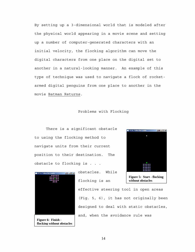
Problems with Flocking
There is a significant obstacle
to using the flocking method to
navigate units from their current
position to their destination. The
obstacle to flocking is . . .
obstacles. While
flocking is an
effective steering tool in open areas
(Fig. 5, 6), it has not originally been
designed to deal with static obstacles,
and, when the avoidance rule was
Figure 5: Start - flocking without obstacles
Figure 6: Finish - flocking without obstacles

15
implemented, it worked by causing members of the flock to
split apart to avoid the obstacle. Flocking was not meant
to deal with crossing a bridge or navigating through a
series of tunnels. An algorithm closely based on the
flocking method would usually handle these types of
obstacles by changing the vectors of the units to avoid
these obstacles while maintaining some speed. The result
would be a small number of units that successfully
navigated through the obstacle and a
large number of units that evaded the
obstacle by steering away from it,
separating themselves from the leader.
These remaining units would wander
aimlessly within flock formation
because they lost contact with the
leader. In figure 8, all but one of the units eventually
reached the leader after many of them
wandered around the map while the
opening was blocked by other units,
but 30 to 45 extra seconds of
wandering around the map is not a
desirable feature to have in a real-
time game setting. In some types of
Figure 7: Start - flocking with obstacles
Figure 8: Finish - flocking with obstacles

16
maps, the leader may be the only unit that reaches the
destination, leaving the other units stranded.

17
CHAPTER III
PROPOSAL
Tools for Obstacle Management
This paper introduces four tools to address obstacle
management in an RTS context: chaining, memory, navigation
markers, and dynamic leadership. These tools were devised
to address two major problems that would cause a flock to
not reach its destination. The first problem is a follower
blocking the leader, and the second is a follower that has
lost contact with the leader. The forms that these two
problems take in an RTS game are described below.
To address this problem, the different types of
scenarios related to encountering an obstacle must be
identified. The solution to each of these scenarios would
serve as a supplemental tool that can be applied to the
flocking model to yield a model more suitable for
simulating the movement patterns of people through terrain
that includes obstacles. This project deals with three

18
types of obstacles. They are congestion, loss of contact
with leader, and leader blocked by follower.
Congestion refers to a
bottleneck type of
obstacle. When a large
number of moving units
encounter a narrow
passageway to cross, only a
few of the units can cross
the obstacle at a time (Fig. 9). This creates a bottleneck
effect, where numerous units cannot proceed until the units
in front of them have crossed the obstacle. The standard
flocking method would change the vector of the units which
are unable to cross the obstacle right away so that they
would avoid the obstacle altogether. While the avoidance
rule of flocking is satisfied, the units have moved “off
course” from the leader and become separated. The solution
to this problem is to tweak the avoidance rule to limit the
angle of deviation from an obstacle and allow the speed of
the units to reach 0 when an obstacle is encountered that
cannot be avoided without losing contact with the leader.
Implementing these two changes to the avoidance rule
results in a flock whose members wait at the bottleneck for
an opening to navigate instead of a flock whose members
Figure 9: Congestion obstacle
19
evade the bottleneck obstacle entirely when they cannot
cross the obstacle right away.
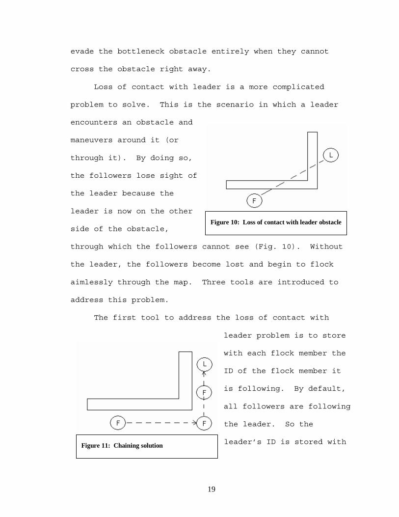
Loss of contact with leader is a more complicated
problem to solve. This is the scenario in which a leader
encounters an obstacle and
maneuvers around it (or
through it). By doing so,
the followers lose sight of
the leader because the
leader is now on the other
side of the obstacle,
through which the followers cannot see (Fig. 10). Without
the leader, the followers become lost and begin to flock
aimlessly through the map. Three tools are introduced to
address this problem.
The first tool to address the loss of contact with
leader problem is to store
with each flock member the
ID of the flock member it
is following. By default,
all followers are following
the leader. So the
leader’s ID is stored with
Figure 10: Loss of contact with leader obstacle
Figure 11: Chaining solution
20
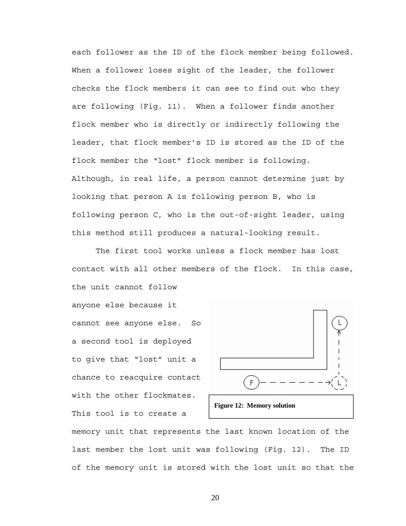
each follower as the ID of the flock member being followed.
When a follower loses sight of the leader, the follower
checks the flock members it can see to find out who they
are following (Fig. 11). When a follower finds another
flock member who is directly or indirectly following the
leader, that flock member’s ID is stored as the ID of the
flock member the “lost” flock member is following.
Although, in real life, a person cannot determine just by
looking that person A is following person B, who is
following person C, who is the out-of-sight leader, using
this method still produces a natural-looking result.
The first tool works unless a flock member has lost
contact with all other members of the flock. In this case,
the unit cannot follow
anyone else because it
cannot see anyone else. So
a second tool is deployed
to give that “lost” unit a
chance to reacquire contact
with the other flockmates.
This tool is to create a
memory unit that represents the last known location of the
last member the lost unit was following (Fig. 12). The ID
of the memory unit is stored with the lost unit so that the
Figure 12: Memory solution

21
unit can follow what it “remembers” to be the last location
of the unit it was following until it reaches that
location. The memory unit is created when a flock member
becomes lost and is destroyed when the flock member reaches
the location. This tool also yields results that appear
natural and can be quite effective for navigating around
corners of obstacles.
The first two tools provide an effective method for
followers to maintain contact with the leader and,
ultimately, arrive at the leader’s destination with the
leader. However, both of these tools fail if a unit has
lost contact with all other units and cannot reacquire
contact with them after navigating to their last known
position. The last resort for these lost units to find
their way to the leader is for the leader to leave a trail
for the lost units to follow. This is implemented by the
creation of a list of
waypoint markers placed by
the leader for the units to
find when they become lost.
Not every space in the
leader’s path has to be
marked; only the ones where
the leader changes direction requires marking. The markers
Figure 13: Navigation marker solution

22
are indexed to indicate the relative position of the
location in the leader’s path (Fig. 13). So, followers who
are lost and cannot find anyone to follow can follow these
markers to the leader’s destination, where the unit
reunites with the rest of the flock. This tool does not
produce natural-looking results because it is not
reasonable for a lost unit to be able to find its way to
the leader on its own in the most efficient manner
possible. However, this tool may be required in the RTS
gaming context because players should not be expected to
baby-sit lost units and herd them back to the flock. In
RTS games, the player must rely on the units ability to
reach a destination, even if natural movement has to be
sacrificed.
Leader blocked by
follower is a scenario that
can be encountered in a
number of situations, which
includes fighting in
battles, encountering
obstacles, or changing a destination. Regardless of what
may cause a leader to be blocked by one of its followers,
the result is a leader who cannot reach a destination
because the path is blocked by one or more of its followers
Figure 14: Leader blocked by follower

23
(Fig. 14), and the followers do not move because their
objective is to stay with the leader. To address this
problem, 2 additional designations are added to the list of
possible designations for each unit. When a leader becomes
blocked by a follower, the leader’s designation changes
from leader to temporary follower, and the unit blocking
the leader changes its
designation from follower
to temporary leader (Fig.
15). The ID of the
temporary leader is stored
with the temporary follower
to make the original leader
follow the new leader. The temporary leader then receives
knowledge of the path to be taken and follows that path
until it reaches the destination or is blocked by another
follower.
Implementation: Building a Sample Navigation Engine
To test the modifications to flocking, a generic RTS
flocking engine is constructed. It basically is a finite
state machine (FSM) that cycles continuously. This FSM is
significantly less-sophisticated than a full-scale game
Figure 15: Dynamic flock leadership

24
engine, which would include other elements, such as teams,
objectives, unit statistics, unit creation, unit actions,
etc. However, this model is sufficient for demonstrating
the effectiveness of chaining, memory, navigation markers,
and dynamic leadership for navigating a flock from one
location on the map to another. During each cycle, the
state of each unit is checked. Based on that state, a set
of instructions runs to update the unit on the screen. The
screen displays a map, which represents the “world” in
which the units move. It is a 2-dimensional map with a
predefined width and height. The units are not allowed to
move beyond the boundaries of the map. The map also
contains obstacles, which represents impassable terrain.
The units are not allowed to pass through obstacles,
either. This engine also contains a destination, which is
a location to which all units are to go.
Ingredients of the engine
Map The map is a rectangular region in which the units are
located. Maps have a predefined width and height, which
defines the boundaries for unit locations. Units are not
allowed to navigate beyond the boundaries of the map.
Locations are referenced in this region using a 2-

25
dimensional coordinate (x,y). The unit of measure using
map coordinates is map units. The following pieces of data
govern the map:
- width(integer): This number determines the width of
the map in number of map units.
- height(integer): This number determines the height
of the map in number of map units.
- map(dynamic integer array): This structure is a
representation of the map with each coordinate occupying a
location in the array. The size of the map is equal to the
width of the map times the height of the map times the data
type of the array. In this case, an integer is being used,
but other data types can be used, depending on the
requirements of the engine.
Static Obstacles Static obstacles are locations on the map
that are not passable. Impassable terrain is commonly used
in RTS games to make games more interesting and add more
elements to strategy component of an RTS game. Impassable
terrain can represent anything including oceans, mountains,
forests, caverns, space, etc. In this exercise, an
obstacle is defined by the map coordinate it occupies. The
obstacle completely fills the region defined by the map
coordinate, which is 1 map units2. Units are not allowed to
occupy this location, nor are they allowed to move

26
diagonally around this location. The following pieces of
data governs static obstacles:
- map(offset): This location is an offset of the map
structure defined by the parameters of the map. The value
in this structure determines whether or not an obstacle
occupies this location. In this exercise, a value of 0
indicates passable terrain, and a value of 1 indicates
impassable terrain.
Destination The destination is a location on the map to
which all units are to move. In an RTS game, this is a key
component in the standard user interface cycle. The cycle
consists of: 1) Select units to move, and 2) Select a
destination for the units. The location of the destination
can be any location inside the boundaries on the map, as
long as it is not also the location of an obstacle.
Destinations are governed by the following pieces of
information:
- xdestination(integer): This integer represents the
x-coordinate of the destination on the map.
- ydestination(integer): This integer represents the
y-coordinate of the destination on the map.
Path A path is a list of coordinates to follow for
navigation from a unit's current location to its
destination. Pathfinding is one of the most important AI

27
components in an RTS game and can also be one of the most
resource-intensive operations. A popular choice for
constructing a pathfinder for an RTS game is A*, which is
used in this exercise to find a path from the destination
to the leader. The following pieces of data are used to
operate the pathfinding component of this program:
- pathnode structure
- x-coordinate(integer): This integer represents
the x-coordinate of the map location being examined for
pathfinding.
- y-coordinate(integer): This integer represents
the y-coordinate of the map location being examined for
pathfinding.
- previous pathnode(pathnode pointer): This
pointer points to the location on the map from which the
current location is reached. This field is used to
navigate the leader to the destination after a route to the
destination is found.
- g-cost(float): This number represents the
movement cost from the destination to the current node
being examined.
- h-cost(float): This number represents an
estimate of the movement cost from the current position to

28
the leader. Both g-cost and h-cost is used to find the
shortest possible path from the destination to the leader.
Units Units are the computer characters that are controlled
by a player in an RTS game. Common type of commands that a
player can issue to a unit is to move, attack, defend,
hide, use special abilities, etc. For this exercise, the
move command is processed. These units move from their
starting location on the map toward the destination. Their
shape is a regular octagon with an apothem of 0.3 map
units. One unit can move diagonally around another unit,
but it cannot move diagonally around an obstacle. Because
units have state information, they require more attention
when coding to manage the state transisions. Here is the
information associated with each unit:
- unit structure
- x-position(float): This number represents the
current animated x-coordinate of the unit on the map.
- y-position(float): This number represents the
current animated y-coordinate of the unit on the map.
- from-x(integer): This integer represents the
x-coordinate on the map from which the unit is moving to
its next location.

29
- from-y(integer): This integer represents the
y-coordinate on the map from which the unit is moving to
its next location.
- to-x(integer): This integer represents the x-
coordinate on the map to which the unit is currently
moving.
- to-y(integer): This integer represents the y-
coordinate on the map to which the unit is currently
moving.
- designation(character): This character
represents the current designation of the unit. The
designation of the unit influences how it behaves.
- L: leader
- l: temporary leader
- F: follower
- f: temporary follower
- M: memory (special units only)
- N: navigation marker (special units only)
- status(character): This character represents
the current status of the unit. The status of the unit
determines what action it takes next.
- N: idle
- M: moving
- B: blocked

30
- L: lost
- unit's leader(unit pointer): This pointer
indicates what this unit is following. Initially, it
follows the leader but can change to another follower, the
memory of a leader or follower's location, or even markers
left by the leader.
- next unit(unit pointer): This pointer
indicates the next unit in the unit list. This list is
constructed at the beginning of program execution from
units loaded from the unit file.
Unit state information
Designations The leader is the one unit on the screen that
has global knowledge of the map and the path required to
reach a destination. This unit navigates exclusively
according to the path that leads that unit to the
destination. A leader can become a temporary follower if
it is blocked by a follower (Fig. 16).
The followers are units that do not have global
knowledge of the map, nor do they have knowledge of the
path that the leader is taking. To reach the destination,
they are dependent on guidance from the leader. These
units navigate according to the RTS directed flocking

31
guidelines. A follower can become a temporary leader if it
blocks a leader or a temporary leader.
A temporary follower is what a leader becomes after it
has been blocked by one of its followers and passes
leadership status to that unit. When a leader becomes a
temporary follower, it no longer has global knowledge of
the map or the path required to reach the destination. It
uses RTS directed flocking to follow the new leader to the
destination. A temporary follower can become a leader
again if it blocks a temporary leader.
A temporary leader is a follower that has blocked a
leader or a
temporary leader
and has received
leadership status
from them. A
temporary leader
has global
knowledge of the
map and the path
calculated to
reach the
destination. It navigates to the destination the same way
that the original leader did, which was by following the
Figure 16: Unit designation state diagram
L: Leader l: Temporary Leader F: Follower f: Temporary Follower

32
calculated path. A temporary leader can become a follower
again if it is blocked by a follower.
Special units are not really units. They describe a
location but do not have a physical shape or size. They
are more like navigation points used to aid lost followers.
Two types of special units are being used in accordance
with RTS directed flocking to help followers that need it.
Memory units are special units that represent the last
known location of a unit that the lost unit was following
before contact was lost. Memory units are dynamically
created when the follower lost contact with the unit it was
following and assigned as the unit to follow. So the
follower goes to where it last saw the unit it was
following. When the follower reaches the memory unit, the
memory unit is destroyed, and the follower attempts to
reestablish visual contact with other units.
Marker units are special units that represent a
direction change made by the leader. When a leader changes
direction, it dynamically creates a marker for lost
followers to find. If necessary, the followers can follow
the trail of markers all the way to the destination,
although it may look a bit unnatural. These markers are
not destroyed in this program until the program exits, but,

33
in a game, a marker can be destroyed after all units have
passed it while moving towards the destination.
Statuses Idle units either are at their initial state or
have just completed a move from one location to the next.
The next action for an idle unit is to determine its next
move. If it can find a move to make, its status changes
from idle to moving (Fig. 17). If all possible moves are
blocked by other
units, its status
changes to blocked.
If it has lost
contact with all
other units, has
reached the memory
unit, and cannot find
any other units or
markers, its status
changes from idle
to lost.
Moving units are currently in motion from its previous
position to its next position. The unit's current position
progressively changes from its previous location to its
next location until the new position is reached. Once the
Figure 17: Unit status state diagram
I: idle M: moving B: blocked L: lost

34
unit reaches its new location, its status changes from
moving to idle.
Blocked units cannot move to its next position because
it is blocked by other units. These units continue to
search for moves that it can make. Once a move becomes
available, its status changes from blocked to moving.
Lost units have lost all contact with the flock and
currently do not know which direction to go. They can
either continue to move based on its own movement behavior
as a flock of one unit, or it can maintain its current
position. Lost units continue to be lost until contact is
established between that unit and other unit, in which case
its status would change from lost to moving or blocked,
depending on whether a move is available. For this
exercise, no unit should reach this status.
Tasks of the engine
The above components of the engine keep track of some
aspects of an RTS game, like map size, map obstacles,
number of units, location of units, group leader, and
destination. What makes these pieces function are the
different chores that the RTS engine does to continually
update the properties of these pieces.

35
Pathfinding Pathfinding is a core element in an RTS game.
It interprets a player’s request to move a set of units
from location to another as a list of paths for the units
to follow to fulfill that request. In this program, one
path is calculated from the leader’s location to the
destination, which takes place when the user presses the
start key.
The pathfinding algorithm used for this exercise is
A*. This algorithm is popular among computer game
programmers because of its ease of use. At the core of A*
is the concept of estimating a movement cost from a given
position to its goal. We call this cost h, which is
calculated by a heuristic function. In this exercise, h is
simply the distance from the given position to the
destination. Another type of movement cost used in A* is
the cost of moving a unit from the start position to a
given position. This cost is called g. In this program, g
is the total distance traveled to reach the current
position. It is not necessarily the distance between the
current position and the start position. So, two costs can
be associated with every position on a map. The cost of
moving a unit from the start position to a specific
location on a map, and the estimated cost of moving that
unit from there to its destination. The sum of these two

36
costs gives the total cost of the unit's trip from start to
destination (f).
A* uses a collection of nodes to represent movement
cost for any location on the map. Each node contains a map
position, the accumulated movement cost so far (g), the
estimated cost for the rest of the trip to the destination
(h), and a pointer to another node from which this node was
reached. Two lists are used in this algorithm. The open
list contains nodes on paths that have not yet been
explored, and the closed list contains nodes on paths that
have already been explored. For each iteration of A*, a
node is selected from the open list for examination. The
algorithm checks if the node represents the location of the
destination. If so, a path from the starting location to
the destination has been found, and A* stops. Otherwise,
possible locations from the location being examined are
added to the open list as new nodes. For each new node
created, cost information is calculated. The current node
being examined is also assigned as the previous node for
all the new nodes created because those new locations are
reached from the current one. Possible locations for the
creation of new nodes are positions adjacent to the current
position. That is, from a given position, a unit is
allowed to move 1 space up, down, left, right, or

37
diagonally. A node selected from the open list for
examination is placed into the closed list.
The next node to be selected from the open list
depends on the estimated total cost stored on the node.
The goal is to pick the most direct route from the starting
location to the ending location. Such a path would have a
minimal movement cost. So, the next node to be picked from
the open list would have the smallest sum of g and h.
Obstacles or boundaries can be an issue with
pathfinding because choosing a path through in immovable
obstacle is not a desired result. One solution to this
problem would be to add a cost penalty if the location
being examined is the location of an obstacle or if it is
out of bounds. By placing an excessively high cost on
making such a move when that node is created and placed
into the open list, the other nodes in the list that do not
make such illegal moves is examined first.
A* algorithm [Nilsson1]:
1) Create a search graph G, consisting of the start
node. Place the start node in the OPEN list.
2) Create a CLOSED list that is initially empty.
3) If the OPEN list is empty, exit with failure.\
4) Select the first node on OPEN, remove it from
OPEN, and put it on CLOSED. Call this node n.

38
5) If n is the goal node, exit with success. The
solution is a path traced from the current node back to the
start node using the previous node pointers.
6) Expand node n, creating the set M of its
successors. Install these members of M as successors of n
in G.
7) Establish a pointer to n from each of those
members of M that were not already in G. Add these members
of M to OPEN.
8) Reorder the OPEN list in order of increasing f
values. (Ties are broken in favor of deeper nodes in the
search tree).
9) Go to step 3.
Movement calculation Calculating a units next move is
driven by the RTS directed flocking rules based from
Reynolds flocking rules but modified for an RTS game
setting for obstacle management. Each rule calculates a
weighted vector for calculating the next direction for a
follower to move. After all calculations are completed and
averaged, the new direction is assigned to the follower.
Separation acts a force field that repels one unit
from another, maintaining a minimum distance between them.
RTS directed flocking allows one unit to be adjacent to
another. For this exercise, the only type of separation
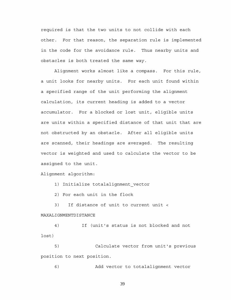
39
required is that the two units to not collide with each
other. For that reason, the separation rule is implemented
in the code for the avoidance rule. Thus nearby units and
obstacles is both treated the same way.
Alignment works almost like a compass. For this rule,
a unit looks for nearby units. For each unit found within
a specified range of the unit performing the alignment
calculation, its current heading is added to a vector
accumulator. For a blocked or lost unit, eligible units
are units within a specified distance of that unit that are
not obstructed by an obstacle. After all eligible units
are scanned, their headings are averaged. The resulting
vector is weighted and used to calculate the vector to be
assigned to the unit.
Alignment algorithm:
1) Initialize totalalignment_vector
2) For each unit in the flock
3) If distance of unit to current unit <
MAXALIGNMENTDISTANCE
4) If (unit's status is not blocked and not
lost)
5) Calculate vector from unit's previous
position to next position.
6) Add vector to totalalignment vector

40
7) End if
8) End if
9) End for
Cohesion works similarly to alignment, except that
instead of averaging the headings of all nearby units, the
vectors from a given unit to the nearby flockmates are
averaged, giving a vector toward the average position of
the units that the given unit saw. Instead of moving in
the same direction of the flock, this rule causes a unit to
move towards the flock.
Cohesion algorithm:
1) Initialize totalcohesion vector
2) For each unit in the flock
3) If distance of unit to current unit <
MAXCOHESIONDISTANCE
5) Calculate vector from current unit's current
position to unit's current position
6) Add vector to totalcohesion vector
7) End if
8) End for
Follow the leader is a rule added for directed
flocking. This rule calculates the vector from a given
unit to a leader, as long as the leader is within visible
range of the given unit and not hidden by any obstacles.

41
Follow the leader algorithm:
1) Initialize followtheleader vector
2) If distance of leader to current unit <
MAXLEADERDISTANCE
4) Calculate vector from current unit's current
position to leader's current position
5) Add vector to followtheleader vector
6) End if
After vectors for alignment, cohesion, and follow the
leader are calculated, the vectors are weighted and
averaged. The resulting vector is used to assign the next
space to which a given unit moves. This vector is weighted
most heavily on follow the leader because contact with the
leader is required to reach a destination. Cohesion takes
second priority, which keep a group of units together.
Alignment is given the lowest priority, and can be used
make movement look more natural for units that are already
in close proximity to each other and have contact with the
leader.
After the directional vector is calculated for a unit
attempting to make a move, it is translated to an angle
that is used to determine a direction that the unit can
attempt to make. The resulting direction can still be
modified by the avoidance algorithm if the direction takes

42
the unit into an obstacle or another unit. The angle to
direction translations are as follows:
- 339 - 360 degrees, 0 - 22 degrees: East
- 23 - 67 degrees: Southeast
- 68 - 113 degrees: South
- 114 - 158 degrees: Southwest
- 159 - 203 degrees: West
- 204 - 248 degrees: Northwest
- 249 - 293 degrees: North
- 294 - 338 degrees: Northeast
Avoidance functions more like an overriding factor
than a weighted factor in RTS directed flocking. After a
new space is calculated for a unit, that new space is check
for obstacles or flockmates. If either are found, then the
new space becomes invalid for the given unit, and alternate
spaces are checked for obstacles. Units are permitted to
deviate from –90 degrees to +90 degrees from the new vector
to find an available space to move. If a space is found,
then that space becomes the next space for the unit.
Otherwise the unit becomes blocked and continues to check
for an opportunity to move to the next space.
Avoidance algorithm:
1) While (next position occupied by obstacle or
another unit) and (vector from current position to next

43
position deviates from unit's directional vector by less
than 90 degrees)
2) Next position = <next closest possible move to
unit's directional vector
3) End while
4) If (vector from current position to next position
deviates from unit's directional vector by 90+ degrees)
5) Unit's status = blocked
6) End if
Animating Moving a unit provides a smooth motion for units
moving from one space to another. A single movement cycle
moves a unit 1/10 of the distance between the unit’s
previous space and the unit’s next space. So, in 10
cycles, a unit has navigated completely from one space to
another.
Animate algorithm:
1) If (distance from unit's current position to unit's
next position is less than 1/10 the distance from the
unit's previous position to the unit's next position)
2) Unit's current position = unit's next position
3) Unit's status = idle
4) Else

44
5) Unit's current position = unit's current position
+ (1/10 * vector from the unit's previous position to the
unit's next position)
6) End if
RTS directed flocking engine interface The interface for
this RTS directed flocking engine is much less
sophisticated than the interfaces found in today's RTS
games. The initial state of the RTS directed flocking
engine is loaded from three data files, which are loaded
when the program first starts.
The map file contains information about the map and
its obstacles. There are two record types in this file.
The first record gives the dimensions of the map in width
and height, both of which are integers delimited by a
space. Each remaining record gives a location of a static
obstacle with and x- and y-coordinate, again delimited by a
space.
The map parameters are loaded into the map width and
height variables, defining the boundaries of the map. Then
a structure in memory is allocated and initialized to
represent the map. As each obstacle record is loaded, that
location in memory has its value changed from 0 to 1,
indicating the presence of an impassable obstacle at that
location.

45
The path file contains the destination, which is given
as an x-coordinate, a space, and a y-coordinate. When this
record is loaded, the destination variables are set and
used to calculate a path from the leader to the
destination.
The unit file contains the starting locations for all
units being loaded into the map. The first unit record is
the leader, and the remaining records are all followers.
Each location is given as an x-coordinate and a y-
coordinate, delimited by a space.
All units loaded are placed into a unit list. Each
unit's current position, previous position, and next
position is initialized to the position loaded from the
unit file. The leader has an initial designation of 'L'
and an initial unit leader of NULL, while the remaining
units have an initial designation of 'F' and the leader as
the initial unit leader. All units initially have an idle
status.
A graphics screen is used to display the elements of
the RTS directed flocking engine. Obstacles appear as red
squares. Units appear as small octagons. The destination
is displayed as a small, white square. Keyboard zoom
controls are available for adjusting what is viewed on the
screen. The following zoom controls are available:

46
- +: Zoom in
- -: Zoom out
- A: Scroll right
- D: Scroll left
- W: Scroll down
- X: Scroll up
Initially, the screen is static. No activity takes
place until the start key (g) is pressed. Once the start
key is pressed, the pathfinder algorithm executes to find a
path for the leader. Once that is completed, the units
start to move toward the destination. At any time, the
program can be terminated by pressing the quit key (q).
RTS engine update cycle walkthrough
When all of the above routines operate on the objects
in memory, the result in a digital recreation of moving a
flock of units from one place to another while calculating
a path for only the leader. The state information of each
unit is updated by running a continuous update cycle, which
checks each unit and updates it according to its status and
the status of the environment (Fig. 18). The following
walkthrough provides a clearer understanding of what
happens within a single update cycle.
Leader / temporary leader cycle update For idle leaders,
the next position in the leader's path is checked to see if

47
it is currently occupied by another unit or if it is
currently the next location of another unit. If so, then
the leader is blocked by that follower. The leader's
designation is changed to temporary follower, and the
leader's status is changed to blocked. The follower's
designation is changed to temporary leader and assumes
leadership of the flock. However, if the next location in
the path is not blocked by a follower, then that location
becomes the next location of the leader. The leader's
current location becomes its previous location, and the
leader's status is changed from idle to moving.
A moving leader is currently in transit to its next
location. Its current position is first checked to see if
it within 1/10 the distance from its previous location and
its next one. If so, then the leader's current position is
changed to its next location, and its status is changed
from moving to idle. If the leader is not within range of
its next location yet, then its current position is changed
by 1/10 of the vector from its previous location to its
next one, bringing it closer to its next position.
Leaders cannot become blocked or lost. A leader who
is blocked by a follower transfers leadership to that
follower and becomes a blocked temporary follower. So, the
leader is no longer the leader. As for being lost, the

48
leader is following the path to the destination, so it
cannot become lost in this exercise.
Follower update cycle Idle followers attempt to find their
next positions. To accomplish this, the engine first calls
the three flocking functions to get vectors for follow the
leader, cohesion, and alignment. The resulting three
vectors are weighted and averaged. Afterwards, an angle is
calculated from that vector. This angle represents the
follower's next heading. This next heading then translated
to the follower's proposed next move (N, NE, E, SE, S, SW,
W, or NW). This move is then tested for static obstacles
or other units. If that move is not available, then all
moves within 45 degrees of the attempted move is checked
for obstacles. If an available location is found, then
that location becomes the follower's next location. The
follower's current location then becomes its previous
location, and its status changes from idle to moving. If
no available space is found, then the follower's status
changes to blocked. If no other units are visible to the
follower, and if the follower cannot find an available
memory unit or a marker unit, then its status changes from
idle to lost.
Followers move the same way as the leader (or
temporary leader). Followers with a current status of

49
moving are updated with a position change that
progressively moves its current location closer to its next
position. When the follower is close enough to its next
position, then its next position becomes its current
position, and its status changes from moving to idle.
Blocked and lost followers follow the same procedure
as idle followers. They continue to attempt to find
another move until it finds one.
Temporary leaders behave the same way as followers do.
It follows the rules of RTS directed flocking for
navigation until it becomes the leader again.

50
Figure 18: Complete unit state diagram
IL: idle leader Il: idle temp leader IF: idle follower If: idle temp follower ML: moving leader Ml: moving temp leader MF: moving follower Mf: moving temp follower BF: blocked follower Bf: blocked temp follower LF: lost follower Lf: lost temp follower

51
CHAPTER IV
RESULTS
A directed flocking simulator with the new obstacle
management tools was written in C. The program contained
2535 lines of code and 36 lines of documentation. This
program was used to perform the following experiments.
Three types of tests were conducted with the obstacle
management tools. The first set of tests includes a
variety of maps, units and destinations, which test the
validity of the tools in specific situations. By testing a
sample of conditions that lead to obstacle-related
problems, one can achieve a general idea of the tools'
effectiveness in dealing with obstacles.
The second set of tests log the elapsed time for each
cycle in the navigation engine. Instead of using several
different maps, a single map reproduced to several
different scales are used to test the playability limits of
the engine. Each scaled map is tested with a different
number of

52
units to further determine the capabilities of the engine.
The first two sets of tests were conducted in two
modes. The first mode sets the speed of all units to the
same magnitude, when moving. The second mode doubles the
speed of units that have lost contact with the leader or
were over 10 units away from the leader. This mode allows
the straggling units to catch up with the leader.
The third set of tests also measures the elapsed time
for each cycle in the navigation engine. Unlike the second
test, this test compares performance between a map with no
obstacles against a map with a bottleneck obstacle.
Validation Results
A total of 11 tests were conducted to determine if all
units could reach a specific destination. These tests
range from testing a single type of obstacle to testing
situations encountered in an RTS game. The test results
are as follows:

53
Test 1
Size of map: 25 x 25
Number of units: 26
Result: OK
This test features a progressive bottleneck. As the
units pass through more obstacles, the bottlenecks become
more extreme. This map tests the ability of the blocked
units to remain with the flock and pass through the
obstacle when the opening finally becomes available.
Figure 1 9: Test 1 Start
Figure 20: Test 1 Finish (Catchup disabled)
Figure 21: Test 1 Finish (Catchup enabled)

54
Test 2
Map size: 25 x 25
Number of units: 26
Result: OK
This test features a single bottleneck. The units
move in a relatively normal fashion until they reach the
obstacle, through which only one unit can pass at a time.
Like the previous map, this map tests the ability of the
blocked units to remain with the flock and pass through the
obstacle when the opening finally becomes available.
Figure 22: Test 2 Start
Figure 23: Test 2 Finish (Catchup disabled)
Figure 24: Test 2 Finish (Catchup enabled)

55
Test 3
Map size: 25 x 25
Number of units: 2
Result: OK
This test features a leader, a follower, and a single
obstacle. As the leader moves behind the obstacle, the
follower loses sight of the leader because the sight is
blocked by the obstacle. This map tests the follower's
ability to use its memory of the leader's position to move
its leader's former position and reacquire contact with the
leader.
Figure 25: Test 3 Start
Figure 27: Test 3 Finish (Catchup enabled)
Figure 26: Test 3 Finish (Catchup disabled)

56
Test 4
Map size: 25 x 25
Number of units: 2
Result: OK
This test also features a leader and a single
follower. The map is a bit more complex. This map tests
the follower's ability to follow the markers dropped by the
leader to reacquire contact with the leader near the
destination.
Figure 28: Test 4 Start
Figure 30: Test 4 Finish (Catchup enabled)
Figure 29: Test 4 Finish (Catchup disabled)

57
Test 5
Map size: 25 x 25
Number of Units: 26
Result: OK
This test places the leader at the rear of the flock.
The leader is unable to proceed because its path is blocked
by followers. Specifically, this map tests the leader's
ability to transfer leadership to the follower blocking it.
Figure 31: Test 5 Start
Figure 33: Test 5 Finish (Catchup enabled)
Figure 32: Test 5 Finish (Catchup disabled)

58
Test 6
Map size: 25 x 25
Number of Units: 26
Result: OK
Similar to test 5, the leader is again at the rear of
the flock. Although it has some room to move, it is soon
blocked by its followers as it moves toward the
destination. This map also tests tests the leader's
ability to transfer leadership to the follower blocking it.
Figure 34: Test 6 Start
Figure 36: Test 6 Finish (Catchup enabled)
Figure 35: Test 6 Finish (Catchup disabled)

59
Test 7
Map size: 25 x 25
Number of units: 26
Result: OK
This test simulates terrain that can be found in an
RTS game. The map is composed of two land masses connected
by three bridges. This map tests the flock's ability to
cross a bridge.
Figure 37: Test 7 Start
Figure 38: Test 7 Finish (Catchup disabled)
Figure 39: Test 7 Finish (Catchup enabled)

60
Test 8
Map size: 25 x 25
Number of units: 26
Result: OK
This test uses the same map as the previous test but
also simulates an ambush at the bridge being crossed,
forcing the flock to retreat back across the bridge. This
map tests the flock's ability to cross a bridge with the
leader starting behind the followers.
Figure 40: Test 8 Start
Figure 42: Test 8 Finish (Catchup enabled)
Figure 41: Test 8 Finish (Catchup disabled)

61
Test 9
Map size: 25 x 25
Number of units: 25
Result: OK
This test features scattered obstacles and scattered
units. The followers in this test are not adjacent to the
leader but do have visual contact with the leader. This
map test the scattered flock's ability to reach the
destination.
Figure 43: Test 9 Start
Figure 45: Test 9 Finish (Catchup enabled)
Figure 44: Test 9 Finish (Catchup disabled)

62
Test 10
Map size: 25 x 25
Number of units: 25
Result: OK
This test uses the same map as test 4 but uses more
followers, creating traffic and occasional traffic jams.
As units become blocked, they start using more of the
obstacle management tools in an attempt to get moving
again. This map tests the flocks ability to reach the
destination in an increased traffic setting.
Figure 46: Test 10 Start
Figure 47: Test 10 Finish (Catchup disabled)
Figure 48: Test 10 Finish (Catchup enabled)

63
Test 11
Map size: 25 x 25
Number of units: 25
Result: OK
This test is a variation of test 9 but with a
different destination. The leader's path in this test is
less direct, as it weaves around the obstacles. This map
tests the scattered flock's ability to reach the
destination when the path is less straightforward.
Figure 49: Test 11 Start
Figure 50: Test 11 Finish (Catchup disabled)
Figure 51: Test 11 Finish (Catchup enabled)

64
The above tests demonstrate the ability of chaining,
memory, navigation, and dynamic leadership to allow a group
of units to move from one location to another without
losing cohesion. The tests were successful, but it is
possible for a test to fail if a unit is forced to move to
an alternate location by another unit and if, from this
alternate location, the unit has no contact with any units,
any markers, and its memory of what it was following.
Although the test results do not guarantee that the tools
always work, they do demonstrate a degree of flexibility in
managing obstacles.
A couple of "odd" behaviors were observed during the
validation tests. In test 2 with catchup enabled, the last
unit had to backtrack to the leader's starting location to
reacquire contact with the other units, which had already
moved through the narrow opening in the obstacle. This was
caused from the last unit competing with another unit to
move to the opening in the obstacle on the map. The last
unit was cut off by the other unit and was forced to move
to an alternate location within its field of view. When
the last unit moved to this location, it lost contact with
all other units because they were on the other side of the
obstacle. To reacquire contact, the last unit moved

65
towards the last marker dropped by the leader that it could
see, which was at the leader's starting location.
Another odd behavior was also observed in the test 10
map. The latter half of the path contains a u-turn around
an obstacle to reach a destination. As the followers
approached the u-turn, some of them cut others off, forcing
them to wait or to move to alternate spaces in a direction
away from the u-turn.
Performance Results
Performance tests were conducted on three scaled
versions of the test 10 map. This map features a winding
path for which the units will use a variety of tools to
reach the leader. For each map, elapsed times were
recorded for path calculation and each update cycle for the
screen. Each map is tested with a variety of number of
units to determine the maximum number of units that can be
used without experiencing significant performance
degradation. As stated earlier, an update cycle should not
take longer than 1/10 of a second. Because navigation was
only one component of an update cycle in a commercial RTS
game, this experiment had a target elapsed time of 1/100 of
a second for a multiple-flock environment. These tests

66
were conducted on a PC with a 2.40 GHz Intel Pentium 4 CPU
with 512 MB of RAM. The test results were as follows:
Test 12
Map size: 25 x 25
- 25 Unit test (catchup disabled):
- Cycles to destination: 740
- Best time: 0.000 s
- Worst time: 0.003 s
- Average time: 0.000 s
- 25 Unit test (catchup enabled):
- Cycles to destination: 460
- Best time: 0.000 s
- Worst time: 0.003 s
- Average time: 0.000 s
- 50 Unit test (catchup disabled):
- Cycles to destination: 810
- Best time: 0.002 s
- Worst time: 0.013 s
- Average time: 0.005 s
- 50 Unit test (catchup enabled):
- Cycles to destination: 530
- Best time: 0.002 s
- Worst time: 0.014 s

67
- Average time: 0.006 s
- 100 Unit test (catchup disabled):
- Cycles to destination: 910
- Best time: 0.006 s
- Worst time: 0.027 s
- Average time: 0.016 s
- 100 Unit test (catchup enabled):
- Cycles to destination: 610
- Best time: 0.009 s
- Worst time: 0.027 s
- Average time: 0.018 s
Test 13
Map size: 50 x 50
- 25 Unit test (catchup disabled):
Figure 52: Test 12 Performance
0
0.005
0.01
0.015
0.02
0.025
0.03
25 50 75 100
Units
Tim
e (s
)
Best w/o catchup
Worst w/o catchup
Ave w/o catchup
Best w/ catchup
Worst w/ catchup
Avg w/ catchup

68
- Cycles to destination: 1170
- Best time: 0.000 s
- Worst time: 0.003 s
- Average time: 0.000 s
- 25 Unit test (catchup enabled):
- Cycles to destination: 740
- Best time: 0.000 s
- Worst time: 0.003 s
- Average time: 0.001 s
- 50 Unit test (catchup disabled):
- Cycles to destination: 1290
- Best time: 0.002 s
- Worst time: 0.013 s
- Average time: 0.004 s
- 50 Unit test (catchup enabled):
- Cycles to destination: 770
- Best time: 0.002 s
- Worst time: 0.016 s
- Average time: 0.006 s
- 100 Unit test (catchup disabled):
- Cycles to destination: 1470
- Best time: 0.011 s
- Worst time: 0.047 s
- Average time: 0.024 s

69
- 100 Unit test (catchup enabled):
- Cycles to destination: 820
- Best time: 0.017 s
- Worst time: 0.050 s
- Average time: 0.030 s
- 250 Unit test (catchup disabled):
- Cycles to destination: 1920
- Best time: 0.097 s
- Worst time: 0.595 s
- Average time: 0.288 s
- 250 Unit test (catchup enabled):
- Cycles to destination: 1100
- Best time: 0.195 s
- Worst time: 0.622 s
- Average time: 0.314 s
Figure 53: Test 13 Performance
0
0.1
0.2
0.3
0.4
0.5
0.6
0.7
0 50 100 150 200 250
Units
Tim
e (s
)
Best w/o catchup
Worst w/o catchup
Ave w/o catchup
Best w/ catchup
Worst w/ catchup
Avg w/ catchup
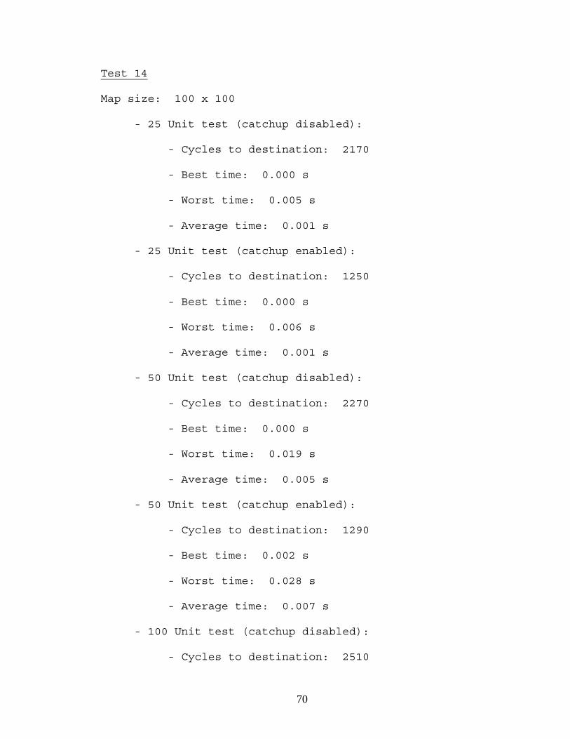
70
Test 14
Map size: 100 x 100
- 25 Unit test (catchup disabled):
- Cycles to destination: 2170
- Best time: 0.000 s
- Worst time: 0.005 s
- Average time: 0.001 s
- 25 Unit test (catchup enabled):
- Cycles to destination: 1250
- Best time: 0.000 s
- Worst time: 0.006 s
- Average time: 0.001 s
- 50 Unit test (catchup disabled):
- Cycles to destination: 2270
- Best time: 0.000 s
- Worst time: 0.019 s
- Average time: 0.005 s
- 50 Unit test (catchup enabled):
- Cycles to destination: 1290
- Best time: 0.002 s
- Worst time: 0.028 s
- Average time: 0.007 s
- 100 Unit test (catchup disabled):
- Cycles to destination: 2510

71
- Best time: 0.000 s
- Worst time: 0.059 s
- Average time: 0.025 s
- 100 Unit test (catchup enabled):
- Cycles to destination: 1390
- Best time: 0.009 s
- Worst time: 0.117 s
- Average time: 0.035 s
- 250 Unit test (catchup disabled):
- Cycles to destination: 2930
- Best time: 0.084 s
- Worst time: 0.984 s
- Average time: 0.232 s
- 250 Unit test (catchup enabled):
- Cycles to destination: 1630
- Best time: 0.153 s
- Worst time: 0.713 s
- Average time: 0.320 s
- 500 Unit test (catchup disabled):
- Cycles to destination: 3830
- Best time: 0.070 s
- Worst time: 5.313 s
- Average time: 1.555 s
- 500 Unit test (catchup enabled):

72
- Cycles to destination: 1950
- Best time: 0.970 s
- Worst time: 4.869 s
- Average time: 1.940 s
These test results reveal that the cycle time for a
specific number of units on a map has little dependence on
the size of the map. The cycle time for 100 units on a map
of one size is close to the cycle time for 100 units on a
map of another size.
The 25 and 50 unit tests reveal an acceptable cycle
time, less than 1/100 of a second. The 100-unit test
begins to show an impact on the system's response time with
an average response time of 2 to 4 hundredths of a second.
Figure 54: Test 14 Performance
0
1
2
3
4
5
6
0 100 200 300 400 500
Units
Tim
e (s
)
Best w/o catchup
Worst w/o catchup
Ave w/o catchup
Best w/ catchup
Worst w/ catchup
Avg w/ catchup

73
Performance continues to degrade with the 250 and 500 unit
tests, which show cycle times ranging from 23/100 of a
second to nearly two seconds.
The code that selects a new unit for a unit to follow
is computationally expensive, as it considers all units on
the map, markers dropped by the leader, and the unit's
memory of its former leader's last known position. This
piece of logic executes every time a unit attempts to
determine the location to which it moves next. When
traffic is light, this logic does not execute all of the
time because the units typically are able to move to the
next location without obstruction. However, in high-
traffic areas, units are constantly blocking each other,
forcing them to continually re-evaluate who to follow as
they attempt to recalculate their next moves.
Enabling the catchup feature allowed the units in the
rear to reach test destination earlier. It also increased
the cycle time by about 25 percent on the average. Units
starting farther away from the leader on a map see the
greatest benefit from using the catchup ability. Units
starting close to the leader see a smaller benefit. Using
the catchup ability can also increase the number of blocked
units by increasing the number of units attempting to
occupy a limited amount of space.

74
Obstacle Performance Results
Obstacle performance tests were conducted on two maps.
The first map is identical to the test 5 map, which has no
obstacles. The second map is similar to the test 2 map,
which features a bottleneck obstacle. For this test, the
bottleneck is located at Y = 13, instead of Y = 11.
Locating the obstacle at this center line on the map allows
more units on either side of the obstacle. For each of the
two maps, elapsed times were recorded for each update cycle
for the screen. Each map is tested with a variety of
number of units to determine the maximum number of units
Figure 55: Cycle Comparison
0 1000 2000 3000 4000 5000
12 / 2512 / 50
12 / 100
13 / 2513 / 50
13 / 10013 / 250
14 / 2514 / 50
14 / 10014 / 25014 / 500
Tes
t / U
nit
s
Cycles
Catchup
Normal

75
that can be used without experiencing significant
performance degradation. Again, the target elapsed time is
1/100 of a second. The test results were as follows:
Test 15
Map size: 25 x 25
- 25 Unit test:
- Best time: 0.000 s
- Worst time: 0.003 s
- Average time: 0.000 s
- 50 Unit test:
- Best time: 0.002 s
- Worst time: 0.013 s
- Average time: 0.005 s
- 100 Unit test:
- Best time: 0.011 s
- Worst time: 0.050 s
- Average time: 0.025 s
Test 16
Map size: 25 x 25
- 25 Unit test:
- Best time: 0.000 s
- Worst time: 0.003 s

76
- Average time: 0.001 s
- 50 Unit test:
- Best time: 0.002 s
- Worst time: 0.013 s
- Average time: 0.009 s
- 100 Unit test:
- Best time: 0.017 s
- Worst time: 0.067 s
- Average time: 0.049 s
This test shows how the presence of an obstacle can
cause the update cycle to degrade in performance. This is
caused by the number of blocked units on the screen.
During an update cycle, a unit either calculates its next
move or is moving to its next position. Calculating a
unit's next position is computationally more expensive than
incrementally updating the unit's position between its
previous position and its next position. The bottleneck
obstacle increases the number of blocked units because only
a few of them can pass through the obstacle at a time. As
the number of units increases, the performance penalty from
the number of blocked units also increases.

77
The optimal number of units for a flock is about 25 -
50 units. The response time for a 25-unit flock is quick
enough to allow a program to manage a significant number of
flocks without experiencing an unacceptable level of
performance degradation. The response time for a 50-unit
flock is quick enough to allow a program to manage a
limited number of flocks of this size without experiencing
an unacceptable level of performance degradation. Although
50 may be too small a number for an epic-scale force, it is
large enough to be usable in many flavors of an RTS game.
0
0.01
0.02
0.03
0.04
0.05
0.06
0.07
0.08
25 50 75 100
Units
Tim
e (s
)best w/o obstacle
worst w/o obstacle
avg w/o obstacle
best w/obstacle
worst w/obstacle
avg w/obstacle
Figure 56: Test 15 / 16 Performance
78
CHAPTER V
CONCLUSION
Pathfinding is a CPU-intensive operation in RTS games,
which makes it a good candidate for optimization.
Calculating a path for only one unit in a group is a good
way to save CPU time, but it also introduces a new problem.
With only one path being used, all units in a group who is
not the group leader must use some type of steering
behavior to keep up with the leader as it moves towards its
destination.
Directed flocking is a good system to use because it
allows followers to track the leader, avoid each other, and
move together in a way that looks natural. The problem
with using flocking in an RTS setting is that obstacles in
the map can cause the group to lose cohesion and fragment
into subgroups. A follower can also be an obstacle if it
blocks the leader from reaching its destination. In this
type of situation, the leader would wait behind the
follower while waiting for it to move. Meanwhile, the

79
followers would wait next to the leader, waiting for the
leader to move.
The tools presented in this paper are effective with
dealing with different types of obstacles in a way that
allow the entire group to reach its destination. While the
experiment does not guarantee success, it does show that
these tools do have the potential to successfully deal with
many different types of obstacles in an RTS game setting.
These tools also appear to be efficient enough to be
deployed in a game without causing significant performance
degradation unless the game allows the user to control over
50 units at a time.
Further study would be necessary to determine if these
tools would be appropriate for an RTS game setting. Some
additional aspects of these tools to study include flock
interaction with allies, enemies, or neutral flocks, flock
interaction with static or moving obstacles, flock members
of different sizes, movement cost, and types of movement.
If the obstacle management tools can work properly under
these type of conditions, then implementing these tools in
a game may become a more feasible idea.
In addition to games, these tools can feasibly be used
in any software system which implements flocking in a way
that emphasizes cohesive movement patterns, which rules out

80
exploration. It can be used in the motion picture industry
to set up flocks which navigate cohesively through
obstacles, whether the flocks be animals, machines, people,
etc. Because of the nature of these tools and how
communication takes place between two units, they may not
be as applicable to robotics, unless the leader robot is
capable of dropping a physical transmitting navigation
marker for other robots to follow. Whether the application
be software, hardware, entertainment, or business, the
obstacle management tools presented may help groups to go
from point A from point B without its members becoming
lost.

81
SELECTED BIBLIOGRAPHY
[Bayazit1] Bayazit, O. Burchan, et al. "Better Flocking Behaviors in Complex Environments using Global Roadmaps." Department of Computer Science, Texas A&M University. TR# TR02-003. URL http:// parasol-www.cs.tamu.edu/dsmft/Papers/tr02-003.pdf. [Bolkan1] Bolkan, J. V. "What's Up With APG?" PC Games, July/August 1998. [CORO1] Collective Robotics Research Group. "Flocking in Embedded Robotic Systems." California Institute of Technology. URL http://www.coro.Caltech.edu/Projects/ Flocking/ab_flocking.htm. [Corne1] Corne, David et al. New Ideas in Optimization. McGraw-Hill International (UK) Limited, 1999. [DeLoura1] DeLoura, Mark A. Game Programming Gems. Charles River Media. 2000. [Fairclough1] Fairclough, Chris, et al. "Research Directions for AI in Computer Games." Trinity College, Dublin 2, Ireland. URL http:// www.cs.tcd.ie/publications/tech-reports/reports.01/ TCD-CS-2001-29.pdf. [Grubb1] Grubb, Thomas G. "Formations Flocking Demo." URL http://riversoftavg.com/formation_flocking.htm. [Kennedy1] Kennedy, J. and Spears, W.M. Matching algorithms to problems: an experimental test of the particle swarm and some genetic algorithms on the multimodal problem generator, in Proceedings of the 1998 International Conference on Evolutionary Computation, IEEE Press, pp. 78-83. [Kennedy2] Kennedy, James, et al. Swarm Intelligence. Morgan Kaufmann Publishers, Inc. 2001.

82
[MASON1] ECLab Evolutionary Computation Laboratory, GMU Center for Social Complexity. "MASON." George Mason University. URL http://cs.gmu.edu/~eclab/projects/ mason/. [Nilsson1] Nilsson, Nils J. Artificial Intelligence: A New Synthesis. Morgan Kaufmann Publishers, Inc. 1998. [Pomeroy1] Pomeroy, Paul. "An Introduction to Particle Swarm Optimization." URL http://www.adaptiveview.com/ articles/ipsoprnt.html. [Reading1] Cybernetic Intelligence Research Group. "Flocking Seven Dwarf Robots." The University of Reading. URL http://www.cyber.rdg.ac.uk/CIRG/robots/ flocking.htm. [Reynolds1] Reynolds, Craig W. "Flocks, Herds, and Schools: A Distributed Behavioral Model." Symbolics Graphics Division. URL http://www.red3d.com/cwr/ papers/1987/SIGGRAPH87.pdf. [Reynolds2] Reynolds, Craig W. "Steering Behaviors For Autonomous Characters." Sony Computer Entertainment America. URL http://www.red3d.com/cwr/steer/gdc99/. [Sweetser1] Sweetser, Penelope. "Current AI in Games: A Review." University of Queensland. URL http:// www.itee.uq.edu.au/~penny/Game%20AI%20Review.pdf. [Tozour1] Tozour, Paul. "The Evolution of Game AI." Ion Storm Austin. URL http://www.charlesriver.com/books/ AIchap.pdf. [Vederman1] Vederman, Greg. "3D's Next Giant Leap." PC Gamer, November 1999. [Woodcock1] Woodcock, Steven. "AI Roundtable Moderator's Report." 2002 Game Developer's Conference. URL http://www.gameai.com/ cgdc02notes.html.

VITA
John Phillip Schneider
Candidate for the Degree of
Master of Science
Thesis: COHESIVE OBSTACLE MANAGEMENT FOR DIRECTED FLOCKING IN REAL-TIME STRATEGY GAMES Major Field: Computer Science Biographical: Education: Graduated from Life Christian School, Oklahoma City, Oklahoma in May 1992; received Bachelor of Science degree in Secondary Math Education with a minor in Computer Science from Oral Roberts University, Tulsa, Oklahoma in May 1996. Completed the requirements for the Master of Science degree with a major in Computer Science at Oklahoma State University in December 2004. Experience: Employed by Eckerd Drug as an over-the- counter drug clerk during summers in high school; employed by Oral Roberts University as a tutor during undergraduate college; employed by Member Service Life Insurance Company as a computer operator, programmer, and programmer analyst, 1997 to present.

Name: John P. Schneider Date of Degree: December, 2004 Institution: Oklahoma State University Location: Tulsa, Oklahoma Title of Study: COHESIVE OBSTACLE MANAGEMENT FOR DIRECTED FLOCKING IN REAL-TIME STRATEGY GAMES Pages in Study: 82 Candidate for the Degree of Master of Science Major Field: Computer Science Scope and Method of Study: The purpose of this study was to introduce additional rules to directed flocking which allowed a flock to navigate obstacles while maintaining cohesion. These rules were chaining, memory, navigation markers, and dynamic leadership. Validation and performance tests were conducted to determine how effective the new rules were and how many units in a flock could be used in a real-time setting. Findings and Conclusions: The new rules were effective in allowing a flock to reach the destination while navigating obstacles. However, a few odd behaviors were observed during testing. The optimal flock size for performance considerations ranged from 25 to 50 units. Units allowed to catch up with the leader after falling behind could do so when bottleneck obstacles were absent, but catching up came at the cost of additional processing overhead. Performance deteriorated when the number of blocked units increased, which occurred when units were blocked by other units or by bottleneck obstacles. ADVISER'S APPROVAL: Dr. Johnson Thomas--------------------------------------------