coil design for high misalignment tolerant inductive power ... · pdf fileenergies article...
TRANSCRIPT

energies
Article
Coil Design for High Misalignment TolerantInductive Power Transfer System for EV Charging
Kafeel Ahmed Kalwar 1, Saad Mekhilef 1,*, Mehdi Seyedmahmoudian 2 and Ben Horan 2
1 Power Electronics and Renewable Energy Research Laboratory (PEARL), Department of ElectricalEngineering, University of Malaya, Kuala Lumpur 50603, Malaysia; [email protected]
2 School of Engineering, Deakin University, Waurn Ponds, VIC 3216, Australia; [email protected] (M.S.);[email protected] (B.H.)
* Correspondence: [email protected]; Tel.: +60-37-967-6851
Academic Editor: Chunhua LiuReceived: 8 August 2016; Accepted: 25 October 2016; Published: 10 November 2016
Abstract: The inductive power transfer (IPT) system for electric vehicle (EV) charging has acquiredmore research interest in its different facets. However, the misalignment tolerance between thecharging coil (installed in the ground) and pick-up coil (mounted on the car chassis), has been achallenge and fundamental interest in the future market of EVs. This paper proposes a new coildesign QDQ (Quad D Quadrature) that maintains the high coupling coefficient and efficient powertransfer during reasonable misalignment. The QDQ design makes the use of four adjacent circularcoils and one square coil, for both charging and pick-up side, to capture the maximum flux at anyposition. The coil design has been modeled in JMAG software for calculation of inductive parametersusing the finite element method (FEM), and its hardware has been tested experimentally at variousmisaligned positions. The QDQ coils are shown to be capable of achieving good coupling coefficientand high efficiency of the system until the misalignment displacement reaches 50% of the employedcoil size.
Keywords: electric vehicle (EV); inductive power transfer (IPT); misalignment tolerance
1. Introduction
The inductive power transfer (IPT) system has proved to be a successful technology for wirelesscharging of electric vehicles (EVs) [1–4]. Due to the reasonable electrical isolation between charging coil(paved in the road) and pick-up coil (embedded in the car chassis), the IPT system has the capability tooperate in grimy conditions [5]. The IPT system is viable because of its inherent advantages of safety,cleanliness and its operation in the dirt, underwater, and harsh weather conditions [3,6]. For wirelesscharging of EVs, it is necessary to have a reasonable ground clearance of a few hundred millimetersbetween the road and the EV chassis, and the ground clearance is also known as the air gap betweenthe charging coil and the pick-up coil [7].
In both dynamic and static charging of EVs through the IPT system, there are certain chancesof alignment displacement between the charging and the pick-up coil. The position of EVs hampersmagnetic coupling [3,8,9]. Thus, the IPT system should be capable of transferring the power undermaximum possible misalignment between the coils [10,11]. At any misaligned position, the powertransmission is substantially contingent on coupling coefficient [4,8,12]. The coupling coefficient ischaracterized by magnetic coupling between the coils and their geometric design [4,12–17].
Considering higher coupling coefficients initial coil designs with U-cores, E-cores, and pot coreswere perused, but these were incompatible with EV due to their greater thickness. Mecke et al. in [18]used circular coils to transfer 1 kW at an air gap of 300 mm. They achieved 80% efficiency for theoverall charging system but did not consider the misalignment. A 2 kW 700 mm diameter circular
Energies 2016, 9, 937; doi:10.3390/en9110937 www.mdpi.com/journal/energies

Energies 2016, 9, 937 2 of 13
charging pad with 200 mm air gap was proposed [19]. The circular pads have exhibited good couplingbut poor tolerance to misalignment because, when misalignment offset approaches ±40%, the outputpower reduces to zero [19]. To solve the issues of circular charging pads, the oval shape pads werepresented. The oval charging pads were slightly more tolerant to misalignment than circular chargingpads; however, they did not transfer high power transfer with the same specifications as those ofcircular pads. Budhia et al. [20] introduced and optimized a new polarized coupler called the DoubleD Quadrature (DDQ) that produced a flux path height twice that of circular charging pad togetherwith a single sided flux path completely interoperable with circular pads.
Since the IPT has been a successful technology for EV charging, it draws considerable attention forthe researchers to find high misalignment tolerant coils to see a future with the massive manufacture ofEVs. This paper presents a new coil design named as QDQ (Quad D Quadrature) has been proposedto enhance the misalignment toleration of coils to a reasonable limit. The proposed design consists offour neighboring small circular coils (forming the slight shape of D) surrounded by a large square coil(forming Quadrature shape) that make a large single coil. Each time, all circular and square coils oncharging and pick-up side are turned on to contribute to the resultant magnetic field. The proposeddesign supports a possible high coupling coefficient at different misaligned positions. To get accuracyin results, the inductive parameters have been calculated using finite element method (FEM) in JMAGsoftware (version 14.0, JSOL Corporation, Tokyo, Japan) and also compared with measured values.Extensive experimental tests have been carried out to validate the functionality of the proposed coil atdifferent misaligned positions of coils with respect to each other. The results have promising efficiencyat reasonable misalignment
2. Proposed Coil Design
Figure 1 presents the design structure of the proposed air cored coil. As shown in the figure, eachcoil consists of four small adjoining circular coils surrounded by one large square coil. The diameterof each circular and square coil is 10 cm and 30 cm, respectively. The charging coil and the pick-upcoil have identical dimensions and number of turns. For inductance analysis in JMAG software, thegeometry editor tool enables the drawing of both identical coils of dimension, i.e., 30 cm × 30 cm,square coil with circular coils inscribed in it, at an air gap of 15 cm between them. Once the geometryof coils is given a shape, the coil material and FEM (finite element method) boundary conditionsare defined. The circuits of both coils are linked to their respective geometry. For the analysis ofself-inductances and mutual inductance, the charging coil is fed with a constant current source feeding1 A, and the resistive load of 1 Ω is connected on the pick-up side. The parameters are calculated usingreal and imaginary parts of respective current and voltages of the coils.
Energies 2016, 9, 937 2 of 13
charging pad with 200 mm air gap was proposed [19]. The circular pads have exhibited good coupling but poor tolerance to misalignment because, when misalignment offset approaches ±40%, the output power reduces to zero [19]. To solve the issues of circular charging pads, the oval shape pads were presented. The oval charging pads were slightly more tolerant to misalignment than circular charging pads; however, they did not transfer high power transfer with the same specifications as those of circular pads. Budhia et al. [20] introduced and optimized a new polarized coupler called the Double D Quadrature (DDQ) that produced a flux path height twice that of circular charging pad together with a single sided flux path completely interoperable with circular pads.
Since the IPT has been a successful technology for EV charging, it draws considerable attention for the researchers to find high misalignment tolerant coils to see a future with the massive manufacture of EVs. This paper presents a new coil design named as QDQ (Quad D Quadrature) has been proposed to enhance the misalignment toleration of coils to a reasonable limit. The proposed design consists of four neighboring small circular coils (forming the slight shape of D) surrounded by a large square coil (forming Quadrature shape) that make a large single coil. Each time, all circular and square coils on charging and pick-up side are turned on to contribute to the resultant magnetic field. The proposed design supports a possible high coupling coefficient at different misaligned positions. To get accuracy in results, the inductive parameters have been calculated using Finite Element Method (FEM) in JMAG software (version 14.0, JSOL Corporation, Tokyo, Japan) and also compared with measured values. Extensive experimental tests have been carried out to validate the functionality of the proposed coil at different misaligned positions of coils with respect to each other. The results have promising efficiency at reasonable misalignment
2. Proposed Coil Design
Figure 1 presents the design structure of the proposed air cored coil. As shown in the figure, each coil consists of four small adjoining circular coils surrounded by one large square coil. The diameter of each circular and square coil is 10 cm and 30 cm, respectively. The charging coil and the pick-up coil have identical dimensions and number of turns. For inductance analysis in JMAG software, the geometry editor tool enables the drawing of both identical coils of dimension, i.e., 30 cm × 30 cm, square coil with circular coils inscribed in it, at an air gap of 15 cm between them. Once the geometry of coils is given a shape, the coil material and FEM (Finite Element Method) boundary conditions are defined. The circuits of both coils are linked to their respective geometry. For the analysis of self-inductances and mutual inductance, the charging coil is fed with a constant current source feeding 1 A, and the resistive load of 1 Ω is connected on the pick-up side. The parameters are calculated using real and imaginary parts of respective current and voltages of the coils.
Pick-up Coil (Rc)
Charging Coil (Tc)
Quad D (circular) coilsOne square coil
Figure 1. Quad D Quadrature (QDQ) coil design model in JMAG software (version 14.0, JSOL Corporation, Tokyo, Japan).
Figure 1. Quad D Quadrature (QDQ) coil design model in JMAG software (version 14.0, JSOLCorporation, Tokyo, Japan).

Energies 2016, 9, 937 3 of 13
The energy transfer from charging coil (Tc) to pick up coil (Rc) changes with the position andshape of the coils. The coils of any shape, having a complex geometry with a current source, generateelectromagnetic fields that can be assessed by considering the contributions of each basic part of thecoil. A uniform current distribution is presumed in each small part of the coil [21]. Both of the coilgeometries, i.e., square and circular, are accounted in the power transfer from the charging coil to thepick-up coil.
On both the charging and pick-up sides, the circular and square coils are connected in seriesmagnetically and in parallel electrically. Since each coil on both sides share the same terminal, i.e.,their dot (.) connection; thus, the polarity of mutual voltage becomes additive. The circular coil formsmagnetic flux loops like an arc; however, the square coil makes a magnetic flux loop of the toroidalform [22].
To simplify the expression for evaluation of both the charging and pick-up side coils, we focus onone circular and one square geometry coil. To evaluate the magnetic field across the circular shapegeometry shown in Figure 2, it is possible to assume them with homocentric circular geometry forfundamental analysis.
Energies 2016, 9, 937 3 of 13
The energy transfer from charging coil (Tc) to pick up coil (Rc) changes with the position and shape of the coils. The coils of any shape, having a complex geometry with a current source, generate electromagnetic fields that can be assessed by considering the contributions of each basic part of the coil. A uniform current distribution is presumed in each small part of the coil [21]. Both of the coil geometries, i.e., square and circular, are accounted in the power transfer from the charging coil to the pick-up coil.
On both the charging and pick-up sides, the circular and square coils are connected in series magnetically and in parallel electrically. Since each coil on both sides share the same terminal, i.e., their dot (.) connection; thus, the polarity of mutual voltage becomes additive. The circular coil forms magnetic flux loops like an arc; however, the square coil makes a magnetic flux loop of the toroidal form [22].
To simplify the expression for evaluation of both the charging and pick-up side coils, we focus on one circular and one square geometry coil. To evaluate the magnetic field across the circular shape geometry shown in Figure 2, it is possible to assume them with homocentric circular geometry for fundamental analysis.
z
y
x
a
y
∆
r
x
Rc
Tc
dlTc
P1
P2
Figure 2. Circular coil geometry set.
The induced voltage in the whole pick-up coil can be calculated by using Faraday’s law as the sum of induced (electromotive force) EMF of all homocentric loops. Thus, the pick-up coil (RC) with n number of homocentric loops with different radii can be evaluated. The same approach will be applied to charging coil (TC).
The geometry of the square shape is shown in Figure 3. The performance of the square geometry coil is entirely different from the circular coil when considered for near-field application. Each turn of the square coil is a homocentric loop, which is divided into four magnetic poles, i.e., dl1, dl2, dl3 and dl4 as shown in Figure 3. The turns are with different lengths for both the charging and pick-up sides.
z
y
x
a
y
∆
r
x
Rc
Tc
dl1
MN
O P
dl2
dl3
dl4
P1
P2
Figure 3. Square geometry coil set.
Figure 2. Circular coil geometry set.
The induced voltage in the whole pick-up coil can be calculated by using Faraday’s law as thesum of induced (electromotive force) EMF of all homocentric loops. Thus, the pick-up coil (RC) with nnumber of homocentric loops with different radii can be evaluated. The same approach will be appliedto charging coil (TC).
The geometry of the square shape is shown in Figure 3. The performance of the square geometrycoil is entirely different from the circular coil when considered for near-field application. Each turn ofthe square coil is a homocentric loop, which is divided into four magnetic poles, i.e., dl1, dl2, dl3 and dl4as shown in Figure 3. The turns are with different lengths for both the charging and pick-up sides.
Energies 2016, 9, 937 3 of 13
The energy transfer from charging coil (Tc) to pick up coil (Rc) changes with the position and shape of the coils. The coils of any shape, having a complex geometry with a current source, generate electromagnetic fields that can be assessed by considering the contributions of each basic part of the coil. A uniform current distribution is presumed in each small part of the coil [21]. Both of the coil geometries, i.e., square and circular, are accounted in the power transfer from the charging coil to the pick-up coil.
On both the charging and pick-up sides, the circular and square coils are connected in series magnetically and in parallel electrically. Since each coil on both sides share the same terminal, i.e., their dot (.) connection; thus, the polarity of mutual voltage becomes additive. The circular coil forms magnetic flux loops like an arc; however, the square coil makes a magnetic flux loop of the toroidal form [22].
To simplify the expression for evaluation of both the charging and pick-up side coils, we focus on one circular and one square geometry coil. To evaluate the magnetic field across the circular shape geometry shown in Figure 2, it is possible to assume them with homocentric circular geometry for fundamental analysis.
z
y
x
a
y
∆
r
x
Rc
Tc
dlTc
P1
P2
Figure 2. Circular coil geometry set.
The induced voltage in the whole pick-up coil can be calculated by using Faraday’s law as the sum of induced (electromotive force) EMF of all homocentric loops. Thus, the pick-up coil (RC) with n number of homocentric loops with different radii can be evaluated. The same approach will be applied to charging coil (TC).
The geometry of the square shape is shown in Figure 3. The performance of the square geometry coil is entirely different from the circular coil when considered for near-field application. Each turn of the square coil is a homocentric loop, which is divided into four magnetic poles, i.e., dl1, dl2, dl3 and dl4 as shown in Figure 3. The turns are with different lengths for both the charging and pick-up sides.
z
y
x
a
y
∆
r
x
Rc
Tc
dl1
MN
O P
dl2
dl3
dl4
P1
P2
Figure 3. Square geometry coil set. Figure 3. Square geometry coil set.

Energies 2016, 9, 937 4 of 13
Applying Ampere’s law across the charging coil (Tc), the magnetic field strength at the pick-upcoil may be found as:
H =ITC
4π
z dl × rr3 (1)
The magnetic field intensity (H) is obvious here and depends on the shape of charging coil andthe location, size, and shape of the pick-up coil. The voltage induced across the pick-up coil can befound by applying Faraday’s law as the rate of change the flux B over the effective surface area S:
Vi = − ∂
∂t
zB · dS (2)
Equation (2) can be expressed asVi = µo ARC jωH (3)
where ARC is the active area of the pick-up coil, and µo is the permeability of the free space. A constantmagnetic flux intercepting over the active area of the pick-up coil is required by Faraday’s law (3) to bevalid.
We proceed here for calculation of magnetic field in the centre of single circular and square coilfrom charging and pick-up sides. The misaligned positions of circular and square coils have beenshown in Figures 2 and 3, respectively. The evaluation of magnetic coupling includes the calculationof the induced voltage across circular and square geometries of the pick-up coil (RC) with the use ofEquation (3) and field strength generated by circular and square geometry on charging coil (TC) byusing Equation (1).
For the circular charging coil, the element of magnetic field intensity can be computed as:
H =ITC
4π
n
∑i=1
ai2
2 (ai2 + D2)
3/2(4)
where i is the radial length of a circular coil of the charging side (TC). The total EMF induced acrossthe pick-up coil can be determined by the addition of discrete contributions of each homocentric loopprovided by (3):
Vi = jµoωH.k
∑j=1
πbj2 (5)
where j is the radial length of a circular coil of the pick-up side. Subsequently, the efficiency includesthe coupling between circular coils can be represented as the following:
ηC =µoπ2ω2
16RTC RRC
.
n
∑i=1
ai2(√
ai2 + D2
)3
2
.
[k
∑j=1
bj2
]2
(6)
With the same approach, the efficiency for a set of loosely coupled square spiral coils is providedby expression:
ηS =µoω2 ARC
2
64π2RTC RRC
.
n
∑i=1
2ai2(
a2
4 + D2)√
a2
2 + D2
2
(7)
Here, i is the magnetic length per pole of charging coil and ARC in Equation (7) is the active areaof the square coil of the pick-up coil, and it can be derived as the accumulation of the field of everysucceeding turn of the coil and calculated as:
A =13
s2N (N − 1) (2N − 1) +din
2
2N + dinsN (N − 1) (8)

Energies 2016, 9, 937 5 of 13
where N is the number of turns, din is the internal span of the square coil, and s is the distanceconcerning each consecutive turn.
The Equations (1)–(8) help in determining the efficiency of power transfer from coil to coil.However, to calculate the efficiency of Inductive Power Transfer (IPT) system, the circuit includesresonant component IPT circuit components on charging and the pick-up side and the load resistorconnected to the pick-up coil. A T-equivalent circuit of IPT system is drawn in Figure 4. LTC andLRC are the self-inductances of the charging and pick-up side coils, respectively, and M is mutualinductance. CTC and CRC are the compensating capacitances of the charging and pick-up side coils.R1 and R2 are the internal resistances of the charging and pick-up coils respectively and RL is theload resistance.
Energies 2016, 9, 937 5 of 13
2
2 2 2
2 2 22 21
2.
644 2
C
C C
o RS
T R
ni
i
A aR R a aD D
μ ωη
π =
=+ +
(7)
Here, i is the magnetic length per pole of charging coil and CRA in Equation (7) is the active
area of the square coil of the pick-up coil, and it can be derived as the accumulation of the field of every succeeding turn of the coil and calculated as:
( )( ) ( )2
21 1 2 1 13 2in
ind
A s N N N N d sN N= − − + + − (8)
where N is the number of turns, din is the internal span of the square coil, and s is the distance concerning each consecutive turn.
The expressions (1)–(8) help in determining the efficiency of power transfer from coil to coil. However, to calculate the efficiency of Inductive Power Transfer (IPT) system, the circuit includes resonant component IPT circuit components on charging and the pick-up side and the load resistor connected to the pick-up coil. A T-equivalent circuit of IPT system is drawn in Figure 4. and are the self-inductances of the charging and pick-up side coils, respectively, and M is mutual inductance. and are the compensating capacitances of the charging and pick-up side coils.R1 andR2are the internal resistances of the charging and pick-up coils respectively and RL is the load resistance.
CRCLTC -MR1
Vs
CTC LRC - M R2
M RL
I1I2
Figure 4. T-equivalent circuit of series-series Inductive Power Transfer (IPT) system.
The coupling coefficient (k), that defines the extent of coupling of the charging and pick-up side coils, is given by:
C CT R
Mk
L L= (9)
The total impedance of the equivalent circuit for given parameters can be calculated as:
2 2
1
2
1
1C
C
C
C
SS TT
R LR
MZ R j L
CR j L R
C
ωωω
ωω
= + − + + − +
(10)
The current absorbed from the supply is given by:
Figure 4. T-equivalent circuit of series-series inductive power transfer (IPT) system.
The coupling coefficient (k), that defines the extent of coupling of the charging and pick-up sidecoils, is given by:
k =M√
LTC LRC
(9)
The total impedance of the equivalent circuit for given parameters can be calculated as:
ZSS =
(R1 + j
(LTC ω − 1
CTC ω
))+
ω2M2
R2 + j(
LRC ω − 1CRC ω
)+ RL
(10)
The current absorbed from the supply is given by:
I1 =Vs
ZSS(11)
I1 =Vs(
R1 + j(
LTC ω − 1CTC ω
))+
ω2 M2
R2+j(
LRC ω− 1CRC
ω
)+RL
(12)
Now, the circuit is operating at a resonant frequency f and the LC components cancel out theirreactance and I1 is given by:
I1 =Vs
R1 +
((2π f )2 M2
R2+RL
) (13)
The input power can be calculated as:
PIN =Vs
2
R1 +
((2π f )2 M2
R2+RL
) (14)

Energies 2016, 9, 937 6 of 13
or:
PIN =Vs
2 (R2RL)
R1R2 + R1RL + (2π f )2 M2(15)
Likewise, the output power can be obtained as below:
POUT =Vs
2 (2π f )2 M2RL(R1R2 + R1RL + (2π f )2 M2
)2 (16)
and the efficiency of the system can be represented by the following equation:
η =POUTPIN
(17)
orη =
RL
RL + R1 ((R2 + RL) / (2π f M))2 + R2(18)
3. System Overview
The capacitors are connected to both charging and pick-up side coils to compensate for theeffect of leakage flux. The arrangement of capacitor connection makes four topologies—series-series(SS), series-parallel (SP), parallel-series (PS) and parallel-parallel (PP). The selection of the topologiesdepends upon their suitability for specific applications satisfying the respective requirements, as SSand SP topologies can transfer higher power than the rated, but these offer an uncertain behavior tothe supply [23], and the PS and the PP compensated IPT systems are safe for the supply in the absenceof pick-up coil, but these are unable to transfer the rated power if the coils are somewhat misaligned.The characteristics of these configurations are summarized in Table 1, which helps in selecting onethem for specific application.
Table 1. Characteristics of compensation topologies.
Topology Power Factor atLonger Distance
Total Impedanceat Resonant State
Suitability forPower Level
Sensitivity toAlignment
Series-Series (SS) Significantly High Low High Power Less SensitiveSeries-Parallel (SP) High Low High Power Less SensitiveParallel-Series (PS) Medium High Low Power Sensitive
Parallel-Parallel (PP) Medium High Low Power Highly Sensitive
To validate the proposed coil design, a prototype of series-series (SS) compensated IPT systemusing QDQ coils is developed as shown in Figure 5. There are two prominent advantages of SS topologyof IPT system. The reflected impedance of pick-up coil to the charging coil does not constitute theimaginary part. It quantifies that it will draw active power when operated at the resonance frequencyand maintain unity power factor. The other advantage is the pick-up coil compensation is independentof resistive load and mutual inductance. According to [16,24], the SS topology is considered as themost suitable for EV charging because the pick-up coil side capacitance is unimpeded from both themagnetic coupling coefficient and the load. It may also act as a constant current and voltage sourcethat is desirable for battery charging [25].

Energies 2016, 9, 937 7 of 13
Energies 2016, 9, 937 7 of 13
of pick-up coil, but these are unable to transfer the rated power if the coils are somewhat misaligned. The characteristics of these configurations are summarized in Table 1, which helps in selecting one them for specific application.
Table 1. Characteristics of compensation topologies.
Topology Power Factor at Longer Distance
Total Impedance at Resonant State
Suitability for Power Level
Sensitivity to Alignment
Series-Series (SS) Significantly High Low High Power Less Sensitive Series-Parallel (SP) High Low High Power Less Sensitive Parallel-Series (PS) Medium High Low Power Sensitive
Parallel-Parallel (PP) Medium High Low Power Highly Sensitive
To validate the proposed coil design, a prototype of series-series (SS) compensated IPT system using QDQ coils is developed as shown in Figure 5. There are two prominent advantages of SS topology of IPT system. The reflected impedance of pick-up coil to the charging coil does not constitute the imaginary part. It quantifies that it will draw active power when operated at the resonance frequency and maintain unity power factor. The other advantage is the pick-up coil compensation is independent of resistive load and mutual inductance. According to [16,24], the SS topology is considered as the most suitable for EV charging because the pick-up coil side capacitance is unimpeded from both the magnetic coupling coefficient and the load. It may also act as a constant current and voltage source that is desirable for battery charging [25].
dSPACE
Gate Drive
DC Supply
Gate Drive SupplyHigh
Frequency InverterQDQ Coils
Charging coil Capacitance
Pick-up coil Capacitance
Position B
Position A
Figure 5. Experimental set-up of the inductive power transfer (IPT) system.
A small figure showing the misaligned position of the coils is also embedded in Figure 5 and marked as “Position B”. The schematic circuit diagram of the experimental set-up is shown in Figure 6. The DC power from the supply is converted to high-frequency AC power with a high-frequency inverter that uses dSPACE (DS1104, dSPACE GmbH, Paderborn, Germany) for high-frequency switching. The high-frequency AC is fed to the compensating capacitor and IPT coils. A resistive load is connected to the receiving side. The SS compensated topology is selected for testing, as it has constant voltage characteristics and that is suitable for charging of EV. To establish the resonance phenomena across coils with their respective capacitances, the resonant frequency f (ωo) has to be maintained [26].
Figure 5. Experimental set-up of the inductive power transfer (IPT) system.
A small figure showing the misaligned position of the coils is also embedded in Figure 5 andmarked as “Position B”. The schematic circuit diagram of the experimental set-up is shown in Figure 6.The DC power from the supply is converted to high-frequency AC power with a high-frequencyinverter that uses dSPACE (DS1104, dSPACE GmbH, Paderborn, Germany) for high-frequencyswitching. The high-frequency AC is fed to the compensating capacitor and IPT coils. A resistiveload is connected to the receiving side. The SS compensated topology is selected for testing, as ithas constant voltage characteristics and that is suitable for charging of EV. To establish the resonancephenomena across coils with their respective capacitances, the resonant frequency f (ωo) has to bemaintained [26].Energies 2016, 9, 937 8 of 13
Mutual Induction
CTC CRC
LRCLTC
High Frequency Inverter
DC
Supp
ly
RL
Figure 6. Schematic circuit diagram of experimental inductive power transfer (IPT) system.
The proposed coil design consists of 10 turns of enameled Litz wire with 0.125 mm strand diameter for each circular and square coil for both charging and pick-up side. The Litz wire is selected to avoid the losses due to the skin effect, as the system circuit will be operated at high frequency. The parameters details are given in Table 2. All of the inductive parameters of charging coil and pick-up coil are measured with PINTEK-900 LCR meter (LCR-900, PINTEK ELECTRONICS CO., LTD, New Taipei City, Taiwan) and verified with accurate values calculated from JMAG software.
Table 2. Parameters of the inductive power transfer (IPT) system.
Symbol Quantity Value LTC Charging coil inductance 46.46 µH LRC Pick-up coil inductance 30.99 µH M Mutual inductance 12.27 µH k Coupling coefficient 0.33 f Resonant frequency 33 kHz
CTC Charging coil compensating capacitance 0.5 µF CRC Pick-up coil compensating capacitance 0.75 µF A Physical dimensions of the coil 30 cm × 30 cm
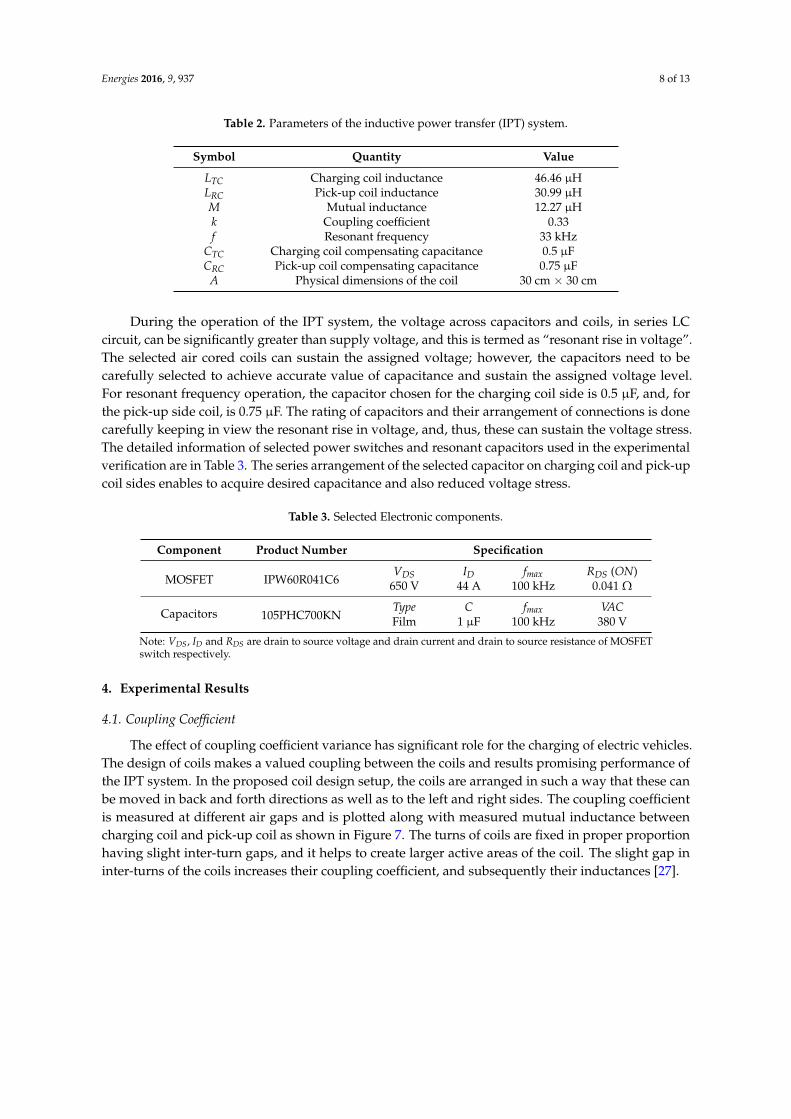
During the operation of the IPT system, the voltage across capacitors and coils, in series LC circuit, can be significantly greater than supply voltage, and this is termed as “resonant rise in voltage”. The selected air cored coils can sustain the assigned voltage; however, the capacitors need to be carefully selected to achieve accurate value of capacitance and sustain the assigned voltage level. For resonant frequency operation, the capacitor chosen for the charging coil side is 0.5 µF, and, for the pick-up side coil, is 0.75 µF. The rating of capacitors and their arrangement of connections is done carefully keeping in view the resonant rise in voltage, and, thus, these can sustain the voltage stress. The detailed information of selected power switches and resonant capacitors used in the experimental verification are in Table 3. The series arrangement of the selected capacitor on charging coil and pick-up coil sides enables to acquire desired capacitance and also reduced voltage stress.
Table 3.Selected Electronic components.
Component Product Number Specification
MOSFET IPW60R041C6 VDS ID fmax RDS (ON)
650 V 44 A 100 kHz 0.041 Ω
Capacitors 105PHC700KN Type C fmax VAC Film 1 µF 100 kHz 380 V
Note: VDS, ID and RDS are drain to source voltage and drain current and drain to source resistance of MOSFET switch respectively.
4. Experimental Results
Figure 6. Schematic circuit diagram of experimental inductive power transfer (IPT) system.
The proposed coil design consists of 10 turns of enameled Litz wire with 0.125 mm strand diameterfor each circular and square coil for both charging and pick-up side. The Litz wire is selected to avoidthe losses due to the skin effect, as the system circuit will be operated at high frequency. The parametersdetails are given in Table 2. All of the inductive parameters of charging coil and pick-up coil aremeasured with PINTEK-900 LCR meter (LCR-900, PINTEK ELECTRONICS CO., LTD, New Taipei City,Taiwan) and verified with accurate values calculated from JMAG software.
Energies 2016, 9, 937 8 of 13
Table 2. Parameters of the inductive power transfer (IPT) system.
Symbol Quantity Value
LTC Charging coil inductance 46.46 µHLRC Pick-up coil inductance 30.99 µHM Mutual inductance 12.27 µHk Coupling coefficient 0.33f Resonant frequency 33 kHz
CTC Charging coil compensating capacitance 0.5 µFCRC Pick-up coil compensating capacitance 0.75 µF
A Physical dimensions of the coil 30 cm × 30 cm
During the operation of the IPT system, the voltage across capacitors and coils, in series LCcircuit, can be significantly greater than supply voltage, and this is termed as “resonant rise in voltage”.The selected air cored coils can sustain the assigned voltage; however, the capacitors need to becarefully selected to achieve accurate value of capacitance and sustain the assigned voltage level.For resonant frequency operation, the capacitor chosen for the charging coil side is 0.5 µF, and, forthe pick-up side coil, is 0.75 µF. The rating of capacitors and their arrangement of connections is donecarefully keeping in view the resonant rise in voltage, and, thus, these can sustain the voltage stress.The detailed information of selected power switches and resonant capacitors used in the experimentalverification are in Table 3. The series arrangement of the selected capacitor on charging coil and pick-upcoil sides enables to acquire desired capacitance and also reduced voltage stress.
Table 3. Selected Electronic components.
Component Product Number Specification
MOSFET IPW60R041C6VDS ID fmax RDS (ON)
650 V 44 A 100 kHz 0.041 Ω
Capacitors 105PHC700KNType C fmax VACFilm 1 µF 100 kHz 380 V
Note: VDS, ID and RDS are drain to source voltage and drain current and drain to source resistance of MOSFETswitch respectively.
4. Experimental Results
4.1. Coupling Coefficient
The effect of coupling coefficient variance has significant role for the charging of electric vehicles.The design of coils makes a valued coupling between the coils and results promising performance ofthe IPT system. In the proposed coil design setup, the coils are arranged in such a way that these canbe moved in back and forth directions as well as to the left and right sides. The coupling coefficientis measured at different air gaps and is plotted along with measured mutual inductance betweencharging coil and pick-up coil as shown in Figure 7. The turns of coils are fixed in proper proportionhaving slight inter-turn gaps, and it helps to create larger active areas of the coil. The slight gap ininter-turns of the coils increases their coupling coefficient, and subsequently their inductances [27].

Energies 2016, 9, 937 9 of 13
Energies 2016, 9, 937 9 of 13
4.1. Coupling Coefficient
The effect of coupling coefficient variance has significant role for the charging of electric vehicles. The design of coils makes a valued coupling between the coils and results promising performance of the IPT system. In the proposed coil design setup, the coils are arranged in such a way that these can be moved in back and forth directions as well as to the left and right sides. The coupling coefficient is measured at different air gaps and is plotted along with measured mutual inductance between charging coil and pick-up coil as shown in Figure 7. The turns of coils are fixed in proper proportion having slight inter-turn gaps, and it helps to create larger active areas of the coil. The slight gap in inter-turns of the coils increases their coupling coefficient, and subsequently their inductances [27].
Figure 7. Mutual inductance and coupling coefficient of QDQ coils.
4.2. Misalignment Tolerance Analysis
Misalignment is the displacement of the pick-up coil with respect to the charging coil that leads to a decline in both the efficiency and power transfer of the IPT system. The IPT system for EV charging requires maximum alignment between the coils to avoid inefficient power transfer due to driver mistake while parking the vehicle at the desired position [28]. The car weight may slightly change the air gap between the EV chassis and the ground, and, thereby, coupling; consequently, it would affect the power transfer efficiency [29]. The IPT charging system with perfect alignment will reduce the leakage flux, and, as a result, it reduces the electromagnetic interference emission from the system; however, an IPT system that could offer good tolerance for misalignment to give maximum freedom to the driver, is desirable [16].
To resolve the misalignment issue, the researchers have proposed control method to tune the IPT coils at the resonance frequency [30,31]. However, this method requires additional electronic components and complex control. In [32], the addition of supplementary coils on both charging and pick-up sides has been considered to reduce the effect of misalignment to a certain limit. However, this requires a large area because of extra coils, hence is not suitable for EV charging application. In addition, it increases the cost and weight of the IPT system.
The prototype of the proposed design has been tested at various positions of coils and power level is set to 700 watts. During misalignment tests, the air gap is fixed to 15 cm, and the pick-up coil is moved in back and forth direction until 30 cm, which is also the length of the coil. Likewise, the pick-up coil is moved in the left and right directions until 30 cm offset. It can be observed from Figure 8 at the centered position, i.e., 0 cm is the power transfer high and begins to decline in both directions at the same rate as the dimensions of the coils are square and identical. The coil maintains excellent efficiency until 15 cm displacement in either direction. The system exhibits an efficiency of 91.8% at 0 cm offset and 78% efficiency at 15 cm offset; the arrows in Figure 8 pointing the power transferred at 15 cm misalignment. At 100% misalignment offset, the efficiency of the IPT system drops drastically. With proposed coil design, the misalignment tolerance is extended to 50% of the coil size
Figure 7. Mutual inductance and coupling coefficient of QDQ coils.
4.2. Misalignment Tolerance Analysis
Misalignment is the displacement of the pick-up coil with respect to the charging coil that leads toa decline in both the efficiency and power transfer of the IPT system. The IPT system for EV chargingrequires maximum alignment between the coils to avoid inefficient power transfer due to drivermistake while parking the vehicle at the desired position [28]. The car weight may slightly change theair gap between the EV chassis and the ground, and, thereby, coupling; consequently, it would affectthe power transfer efficiency [29]. The IPT charging system with perfect alignment will reduce theleakage flux, and, as a result, it reduces the electromagnetic interference emission from the system;however, an IPT system that could offer good tolerance for misalignment to give maximum freedomto the driver, is desirable [16].
To resolve the misalignment issue, the researchers have proposed control method to tune theIPT coils at the resonance frequency [30,31]. However, this method requires additional electroniccomponents and complex control. In [32], the addition of supplementary coils on both charging andpick-up sides has been considered to reduce the effect of misalignment to a certain limit. However,this requires a large area because of extra coils, hence is not suitable for EV charging application.In addition, it increases the cost and weight of the IPT system.
The prototype of the proposed design has been tested at various positions of coils and powerlevel is set to 700 watts. During misalignment tests, the air gap is fixed to 15 cm, and the pick-upcoil is moved in back and forth direction until 30 cm, which is also the length of the coil. Likewise,the pick-up coil is moved in the left and right directions until 30 cm offset. It can be observed fromFigure 8 at the centered position, i.e., 0 cm is the power transfer high and begins to decline in bothdirections at the same rate as the dimensions of the coils are square and identical. The coil maintainsexcellent efficiency until 15 cm displacement in either direction. The system exhibits an efficiency of91.8% at 0 cm offset and 78% efficiency at 15 cm offset; the arrows in Figure 8 pointing the powertransferred at 15 cm misalignment. At 100% misalignment offset, the efficiency of the IPT system dropsdrastically. With proposed coil design, the misalignment tolerance is extended to 50% of the coil sizeand can be considered as a significant improvement [33,34]. There has been work on different designsof coils for the IPT system in which magnetic coupling is sensitive to the position of coils with respectto each other [35,36]. In this proposed IPT system, frequency remains fixed to 33 kHz for all the testsconducted for misaligned positions. The QDQ design of the coil enables maintaining high couplingeven when the coils are misaligned to 50% of their sizes, thus it helps to transfer the power. In addition,the SS compensated IPT system is selected, and operating frequency in this topology is not mainlycontingent on the coupling coefficient.

Energies 2016, 9, 937 10 of 13
Energies 2016, 9, 937 10 of 13
and can be considered as a significant improvement [33,34]. There has been work on different designs of coils for the IPT system in which magnetic coupling is sensitive to the position of coils with respect to each other [35,36]. In this proposed IPT system, frequency remains fixed to 33 kHz for all the tests conducted for misaligned positions. The QDQ design of the coil enables maintaining high coupling even when the coils are misaligned to 50% of their sizes, thus it helps to transfer the power. In addition, the SS compensated IPT system is selected, and operating frequency in this topology is not mainly contingent on the coupling coefficient.
-30
-15
0
15
30
-30
-15
0
15
30200
400
600
800
1000
Pow
er T
rans
ferr
ed (W
)
Figure 8. Power transferred during misalignment in across side and longitudinal direction.
The output voltage and current at resistive load are recorded with a power analyser when the coils have zero offset and also when the coils are misaligned to 50% of their size. Figure 9a presents the output current and voltage waveforms of the IPT system with 15 cm air gaps at different misaligned positions of the coils. The difference in the output current and voltage waveforms in Figure 9b is evident and is recorded under 50% misaligned position of the coils. In addition, the efficiency of the IPT system drops from 91.4% to 78% when the coils are misaligned.
V2=200 V/div
I2=5 A/div
V2=200 V/div
I2=5 A/div
(a)
(b)
Figure 9.Output voltage and current (a) at perfect alignment; and (b) at 50% misalignment.
It is important to follow the electromagnetic compliance described by safety regulation authorities. The reference value of the magnetic field, for operating frequencies of 1 Hz–100 kHz, for general public exposure is set by the International Committee on Non-Ionizing Radiation Protection (ICNIRP) to 27 µT [37,38]. In this research, to avoid the effects of the magnetic field, a tesla meter (ME 3830B) has been used to check the magnetic field intensity in the vicinity. The maximum magnetic
Figure 8. Power transferred during misalignment in across side and longitudinal direction.
The output voltage and current at resistive load are recorded with a power analyser when thecoils have zero offset and also when the coils are misaligned to 50% of their size. Figure 9a presents theoutput current and voltage waveforms of the IPT system with 15 cm air gaps at different misalignedpositions of the coils. The difference in the output current and voltage waveforms in Figure 9b isevident and is recorded under 50% misaligned position of the coils. In addition, the efficiency of theIPT system drops from 91.4% to 78% when the coils are misaligned.
Energies 2016, 9, 937 10 of 13
and can be considered as a significant improvement [33,34]. There has been work on different designs of coils for the IPT system in which magnetic coupling is sensitive to the position of coils with respect to each other [35,36]. In this proposed IPT system, frequency remains fixed to 33 kHz for all the tests conducted for misaligned positions. The QDQ design of the coil enables maintaining high coupling even when the coils are misaligned to 50% of their sizes, thus it helps to transfer the power. In addition, the SS compensated IPT system is selected, and operating frequency in this topology is not mainly contingent on the coupling coefficient.
-30
-15
0
15
30
-30
-15
0
15
30200
400
600
800
1000
Pow
er T
rans
ferr
ed (W
)
Figure 8. Power transferred during misalignment in across side and longitudinal direction.
The output voltage and current at resistive load are recorded with a power analyser when the coils have zero offset and also when the coils are misaligned to 50% of their size. Figure 9a presents the output current and voltage waveforms of the IPT system with 15 cm air gaps at different misaligned positions of the coils. The difference in the output current and voltage waveforms in Figure 9b is evident and is recorded under 50% misaligned position of the coils. In addition, the efficiency of the IPT system drops from 91.4% to 78% when the coils are misaligned.
V2=200 V/div
I2=5 A/div
V2=200 V/div
I2=5 A/div
(a)
(b)
Figure 9.Output voltage and current (a) at perfect alignment; and (b) at 50% misalignment.
It is important to follow the electromagnetic compliance described by safety regulation authorities. The reference value of the magnetic field, for operating frequencies of 1 Hz–100 kHz, for general public exposure is set by the International Committee on Non-Ionizing Radiation Protection (ICNIRP) to 27 µT [37,38]. In this research, to avoid the effects of the magnetic field, a tesla meter (ME 3830B) has been used to check the magnetic field intensity in the vicinity. The maximum magnetic
Figure 9. Output voltage and current (a) at perfect alignment; and (b) at 50% misalignment.
It is important to follow the electromagnetic compliance described by safety regulation authorities.The reference value of the magnetic field, for operating frequencies of 1 Hz–100 kHz, for general publicexposure is set by the International Committee on Non-Ionizing Radiation Protection (ICNIRP) to27 µT [37,38]. In this research, to avoid the effects of the magnetic field, a tesla meter (ME 3830B) hasbeen used to check the magnetic field intensity in the vicinity. The maximum magnetic field is recordedin the centre of the air gap between coils, i.e., 247 nT; thus, the magnetic field around the prototypecan be considered as safe and lies within the limits prescribed by safety regulation authorities forwireless charging.
The magnetic flux density across the charging coil and the pick-up coil are shown in Figure 10.It is evident from Figure 10a, representing the perfect alignment of the coils, that the magnetic field

Energies 2016, 9, 937 11 of 13
captured across the pick-up coil is high. However, when the coils are moved horizontally from eachother as shown in Figure 10b, the field captured by the pick-up coil reduces. As a result, the powerreceived at the pick-up coil gets reduced.
Energies 2016, 9, 937 11 of 13
field is recorded in the centre of the air gap between coils, i.e., 247 nT; thus, the magnetic field around the prototype can be considered as safe and lies within the limits prescribed by safety regulation authorities for wireless charging.
The magnetic flux density across the charging coil and the pick-up coil are shown in Figure 10. It is evident from Figure 10a, representing the perfect alignment of the coils, that the magnetic field captured across the pick-up coil is high. However, when the coils are moved horizontally from each other as shown in Figure 10b, the field captured by the pick-up coil reduces. As a result, the power received at the pick-up coil gets reduced.
(a)
(b)
Figure 10. Magnetic Flux density (a) coils are perfect alignment; and (b) coils are misaligned to 50% of their size.
5. Conclusions
A Quad D Quadrature (QDQ) coil design has been proposed to cope with the misalignment toleration concern of the IPT system for the application of electric vehicles. The analytical evaluation of the magnetic field of circular and square geometry coil has been added. The coil design has shown the capability to capture maximum magnetic coupling at different positions of coils. It uses the resultant magnetic field developed from each of four adjacent circular coils and one square coil on
Figure 10. Magnetic Flux density (a) coils are perfect alignment; and (b) coils are misaligned to 50% oftheir size.
5. Conclusions
A Quad D Quadrature (QDQ) coil design has been proposed to cope with the misalignmenttoleration concern of the IPT system for the application of electric vehicles. The analytical evaluationof the magnetic field of circular and square geometry coil has been added. The coil design has shownthe capability to capture maximum magnetic coupling at different positions of coils. It uses theresultant magnetic field developed from each of four adjacent circular coils and one square coil onboth the charging and pick-up sides. The inductive parameters of the coils have been evaluatedthrough FEM in JMAG software and validated with practically measured values. An IPT system

Energies 2016, 9, 937 12 of 13
prototype has been tested for misalignment tolerance until a 30 cm offset, and the proposed coil designhas shown the capability to overcome the issue. The IPT system exhibits a maximum efficiency of91.4% at the perfectly aligned position of the coils and also maintains an efficiency of 78% at 50%misaligned position of coils. The reported findings encourage the consideration of the proposed designfor commercialized EV charging.
Acknowledgments: This work was supported by the High Impact Research of the University of Malaya—Ministryof Higher Education of Malaysia under Project UM.C/HIR/MOHE/ENG/24 and PPP research grantNo. PG192-2015B.
Author Contributions: Kafeel Ahmed Kalwar has contributed to the theoretical approaches, simulation,experimental tests, and preparing the article; Saad Mekhilef has contributed to the theoretical approaches,simulations, experimental tests, and preparing the article; Mehdi Seyedmahmoudian has contributed to thetheoretical approaches and preparing the article; Ben Horan has contributed to the theoretical approaches andpreparing the article.
Conflicts of Interest: The authors declare no conflict of interest.
References
1. Boys, J.T.; Elliott, G.A.; Covic, G.A. An appropriate magnetic coupling coefficient for the design andcomparison of icpt pick-ups. IEEE Trans. Power Electron. 2007, 22, 333–335. [CrossRef]
2. Madawala, U.K.; Thrimawithana, D.J. A bidirectional inductive power interface for electric vehicles in V2Gsystems. IEEE Trans. Ind. Electron. 2011, 58, 4789–4796. [CrossRef]
3. Del Toro García, X.; Vázquez, J.; Roncero-Sánchez, P. Design, implementation issues and performanceof an inductive power transfer system for electric vehicle chargers with series-series compensation.IET Power Electron. 2015, 8, 1920–1930. [CrossRef]
4. Keeling, N.A.; Covic, G.A.; Boys, J.T. A unity-power-factor IPT pick-up for high-power applications.IEEE Trans. Ind. Electron. 2010, 57, 744–751. [CrossRef]
5. Sallan, J.; Villa, J.L.; Llombart, A.; Sanz, J.F. Optimal design of ICPT systems applied to electric vehicle batterycharge. IEEE Trans. Ind. Electron. 2009, 56, 2140–2149. [CrossRef]
6. Yuan, X.F.; Zhang, Y.L.; Wang, Y.; Li, Z.Q. Output voltage control of inductive power transfer system basedon extremum seeking control. IET Power Electron. 2015, 8, 2290–2298. [CrossRef]
7. Duan, C.; Jiang, C.; Taylor, A.; Bai, K. Design of a zero-voltage-switching large-air-gap wireless charger withlow electric stress for electric vehicles. IET Power Electron. 2013, 6, 1742–1750. [CrossRef]
8. Liao, Y.H.; Yuan, X.Q. Compensation topology for flat spiral coil inductive power transfer systems.IET Power Electron. 2015, 8, 1893–1901. [CrossRef]
9. Zheng, C.; Ma, H.B.; Lai, J.S.; Zhang, L.H. Design considerations to reduce gap variation and misalignmenteffects for the inductive power transfer system. IEEE Trans. Power Electron. 2015, 30, 6108–6119. [CrossRef]
10. Elliott, G.A.J.; Raabe, S.; Covic, G.A.; Boys, J.T. Multiphase pick-ups for large lateral tolerance contactlesspower-transfer systems. IEEE Trans. Ind. Electron. 2010, 57, 1590–1598. [CrossRef]
11. Kurschner, D.; Rathge, C.; Jumar, U. Design methodology for high efficient inductive power transfer systemswith high coil positioning flexibility. IEEE Trans. Ind. Electron. 2013, 60, 372–381. [CrossRef]
12. Hsu, J.U.W.; Hu, A.P.; Swain, A. Fuzzy logic-based directional full-range tuning control of wireless powerpick-ups. IET Power Electron. 2012, 5, 773–781. [CrossRef]
13. Liu, X.C.; Wang, G.F.; Ding, W. Efficient circuit modelling of wireless power transfer to multiple devices.IET Power Electron. 2014, 7, 3017–3022. [CrossRef]
14. Moradewicz, A.J.; Kazmierkowski, M.P. Contactless energy transfer system with FPGA-controlled resonantconverter. IEEE Trans. Ind. Electron. 2010, 57, 3181–3190. [CrossRef]
15. Liu, N.; Habetler, T. Design of a universal inductive charger for multiple electric vehicle models. IEEE Trans.Power Electron. 2015, 30, 6378–6390. [CrossRef]
16. Wang, C.S.; Stielau, O.H.; Covic, G.A. Design considerations for a contactless electric vehicle battery charger.IEEE Trans. Ind. Electron. 2005, 52, 1308–1314. [CrossRef]
17. Grover, F.W. Inductance Calculations: Working Formulas and Tables; Courier Corporation: North Chelmsford,MA, USA, 2004.

Energies 2016, 9, 937 13 of 13
18. Mecke, R.; Rathge, C. High Frequency Resonant Inverter for Contactless Energy Transmission over LargeAir Gap. In Proceedings of the IEEE 35th Annual ower Electronics Specialists Conference (PESC), Aachen,Germany, 20–25 June 2004.
19. Budhia, M.; Covic, G.A.; Boys, J.T. Design and optimization of circular magnetic structures for lumpedinductive power transfer systems. IEEE Trans. Power Electron. 2011, 26, 3096–3108. [CrossRef]
20. Budhia, M.; Boys, J.T.; Covic, G.A.; Huang, C.Y. Development of a single-sided flux magnetic coupler forelectric vehicle IPT charging systems. IEEE Trans. Ind. Electron. 2013, 60, 318–328. [CrossRef]
21. Urankar, L.K. Vector potential and magnetic field of current-carrying finite ARC segment in analytical form,part I: Filament approximation. IEEE Trans. Magn. 1980, 16, 1283–1288. [CrossRef]
22. Kaneko, Y.; Abe, S. Technology trends of wireless power transfer systems for electric vehicle and plug-inhybrid electric vehicle. In Proceedings of the IEEE 10th International Conference on Power Electronics andDrive Systems, Kitakyushu, Japan, 22–25 April 2013.
23. Villa, J.L.; Sallan, J.; Sanz Osorio, J.F.; Llombart, A. High-misalignment tolerant compensation topology forICPT systems. IEEE Trans. Ind. Electron. 2012, 59, 945–951. [CrossRef]
24. Throngnumchai, K.; Kai, T.; Minagawa, Y. A Study on Receiver Circuit Topology of a Cordless BatteryCharger for Electric Vehicles. In Proceedings of the IEEE Energy Conversion Congress and Exposition(ECCE), Phoenix, AZ, USA, 17–22 September 2011.
25. Yilmaz, M.; Krein, P.T. Review of battery charger topologies, charging power levels, and infrastructure forplug-in electric and hybrid vehicles. IEEE Trans. Power Electron. 2013, 28, 2151–2169. [CrossRef]
26. Bhuyan, S.; Sivanand, K.; Panda, S.K.; Kumar, R.; Hu, J. Resonance-based wireless energizing of piezoelectriccomponents. IEEE Magn. Lett. 2011, 2, 6000204. [CrossRef]
27. Mohan, S.S.; Hershenson, M.D.; Boyd, S.P.; Lee, T.H. Simple accurate expressions for planar spiralinductances. IEEE J. Solid-State Circuits 1999, 34, 1419–1424. [CrossRef]
28. Budhia, M.; Covic, G.A.; Boys, J.T. Design and optimisation of magnetic structures for lumped inductivepower transfer systems. In Proceedings of the IEEE Energy Conversion Congress and Exposition, San Jose,CA, USA, 20–24 September 2009.
29. Chigira, M.; Nagatsuka, Y.; Kaneko, Y.; Abe, S.; Yasuda, T.; Suzuki, A. Small-size light-weight transformerwith new core structure for contactless electric vehicle power transfer system. In Proceedings of the IEEEEnergy Conversion Congress and Exposition (ECCE), Phoenix, AZ, USA, 17–22 September 2011.
30. Si, P.; Hu, A.P.; Malpas, S.; Budgett, D. A frequency control method for regulating wireless power toimplantable devices. IEEE Trans. Biomed. Circuits Syst. 2008, 2, 22–29. [CrossRef] [PubMed]
31. Madawala, U.K.; Neath, M.; Thrimawithana, D.J. A power-frequency controller for bidirectional inductivepower transfer systems. IEEE Trans. Ind. Electron. 2013, 60, 310–317. [CrossRef]
32. Kamineni, A.; Covic, G.; Boys, J.T. Analysis of co-planar intermediate coil structures in inductive powertransfer systems. In Proceedings of the IEEE Energy Conversion Congress and Exposition (ECCE), Pittsburgh,PA, USA, 14–18 September 2014.
33. Zhu, Q.W.; Guo, Y.J.; Wang, L.F.; Liao, C.L.; Li, F. Improving the misalignment tolerance of wireless chargingsystem by optimizing the compensate capacitor. IEEE Trans. Ind. Electron. 2015, 62, 4832–4836. [CrossRef]
34. Zhang, W.; White, J.C.; Abraham, A.M.; Mi, C.C. Loosely coupled transformer structure and interoperabilitystudy for EV wireless charging systems. IEEE Trans. Power Electron. 2015, 30, 6356–6367. [CrossRef]
35. Boys, J.; Covic, G.; Green, A.W. Stability and control of inductively coupled power transfer systems. IEE Proc.Electr. Power Appl. 2000, 147, 37–43. [CrossRef]
36. Gao, Y.; Farley, K.B.; Tse, Z.T.H. A uniform voltage gain control for alignment robustness in wireless EVcharging. Energies 2015, 8, 8355–8370. [CrossRef]
37. International Commission on Non-Ionizing Radiation Protection. Guidelines for limiting exposure totime-varying electric and magnetic fields (1 Hz to 100 kHz). Health Phys. 2010, 99, 818–836.
38. Wen, F.; Huang, X. Optimal magnetic field shielding method by metallic sheets in wireless power transfersystem. Energies 2016, 9, 733. [CrossRef]
© 2016 by the authors; licensee MDPI, Basel, Switzerland. This article is an open accessarticle distributed under the terms and conditions of the Creative Commons Attribution(CC-BY) license (http://creativecommons.org/licenses/by/4.0/).